

Page 1

If you have questions or comments, contact us.
Pour toute question ou tout commentaire, nous contacter.
Si tiene dudas o comentarios, contactenos.
INSTRUCTION MANUAL
GUIDE D'UTILISATION
MANUAL DE INSTRUCCIONES
DWE575, DWE575SB
7-1/4" (184 mm) Circular Saws
Scies circulaires de 184 mm (7-1/4 po)
Sierras circulares de 184 mm (7-1/4")
INSTRUCTIVODE OPERACION, CENTROS DE SERVICIOY P©LIZA DE
GARANT/A. ADVERTENCIA: LEASE ESTE INSTRUCTIVOANTES DE
USAR EL PRODUCTO.
®
Page 2
Definitions: Safety Guidelines
The definitions below describe the level of severity br
each signal word. Please read the manual and pay
attention to these symbols.
ADANGER: Indicates an imminently hazardous
situation which, if not avoided, will result in death or
serious injury.
A WARNING: Indicates a potentially hazardous
situation which, if not avoided, could result in death
or serious injury.
A CAUTION: Indicates a potentially hazardous
situation which, if not avoided, may result in minor or
moderate injury.
NOTICE: Indicates a practice not related to
personal injury which, if not avoided, may result in
property damage.
IF YOU HAVE ANY QUESTIONS OR COMMENTS ABOUT THIS OR
ANY DEWALTTOOL, CALL US TOLL FREE AT: 1-800-4-DEWALT
(1-800-433-9258}.
_ ARNING: To reduce the risk of injury, read the instruction
manual.
J
General Power Tool Safety Warnings
_ WARNING! Read all safety warnings and all instructions.
Failure to follow the warnings and instructions may result in
electric shock, fire and/or serious injury,
SAVE ALL WARNINGS AND INSTRUCTIONS
FOR FUTURE REFERENCE
The term "power tool" in the warnings refers to your mains-operated
(corded) power tool or battery-operated (cordless) power tool
1) WORK AREA SAFETY
a) Keep work area clean and well lit. Cluttered or dark areas
invite accidents.
b) Do not operate power tools in explosive atmospheres,
such as in the presence of flammable liquids, gases or
dust. Power tools create sparks which may ignite the dust or
fumes.
c) Keep children and bystanders away while operating a
power tool Distractions can cause you to lose control
2) ELECTRICAL SAFETY
a) Power tool plugs must match the outlet. Never modify
the plug in any way. Do not use any adapter plugs with
earthed (grounded) power tools. Unmodified plugs and
matching outlets will reduce risk of electric shock.
b) Avoid body contact with earthed or grounded surfaces
such as pipes, radiators, ranges and refrigerators. There
is an increased risk of electric shock if your body is earthed or
grounded.
c) Do not expose power tools to rain or wet conditions.
Water entering a power tool will increase the risk of electric
shock.
d) Do not abuse the cord. Never use the cord for carrying,
pulling or unplugging the power tooL Keep cord away
from heat, oil, sharp edges or moving parts. Damaged or
entangled cords increase the risk of electric shock.
e) When operating a power tool outdoors, use an extension
cord suitable for outdoor use. Use of a cord suitable for
outdoor use reduces the risk of electric shock.
Page 3
If operating a powertool in a damp location is unavoidable,
use a ground fault circuit interrupter (GFCI) protected
supply. Use of a GFC/ reduces the risk of electric shock.
3) PERSONAL SAFETY
a) Stay alert, watch what you are doing and use common
sense when operating a power tool. Do not use a
power tool while you are tired or under the influence of
drugs, alcohol or medication. A moment of inattention while
operating power tools may result in serious personal injury.
b) Use personal protective equipment. Always wear eye
protection. Protective equipment such as dust mask, non-
skid safety shoes, hard hat, or hearing protection used for
appropriate conditions will reduce personal injuries.
c) Prevent unintentional starting. Ensure the switch is in
the off position before connecting to power source and/
or battery pack, picking up or carrying the tool. Carrying
power tools with your finger on the switch or energizing power
tools that have the switch on invites accidents.
d) Remove any adjusting key or wrench before turning the
power tool on. A wrench or a key left attached to a rotating
part of the power tool may result in personal injury.
e) Do not overreach. Keep proper footing and balance at
all times. This enables better control of the power tool in
unexpected situations.
Dress properly. Do not wear loose clothing or jewelry.
Keep your hair, clothing and gloves away from moving
parts. Loose clothes, jewelry or long hair can be caught in
moving parts.
g) If devices are provided for the connection of dust
extraction and collection facilities, ensure these are
connected and properly used. Use of dust collection can
reduce dust-related hazards.
4) POWER TOOL USE AND CARE
a) Do not force the power tool Use the correct power tool
for your application. The correct power tool will do the job
better and safer at the rate for which it was designed.
b) Do not use the power tool if the switch does not turn it
on and off. Any power tool that cannot be controlled with the
switch is dangerous and must be repaired.
c) Disconnect the plug from the power source and/or the
battery pack from the power tool before making any
adjustments, changing accessories, or storing power
tools. Such preventive safety measures reduce the risk of
starting the power tool accidentally.
d) Store idle power tools out of the reach of children and do
not allow persons unfamiliar with the power tool or these
instructions to operate the power tool Power tools are
dangerous in the hands of untrained users.
e) Maintain power tools. Check for misalignment or binding
ofmoving parts, breakage of parts and any other condition
that may affect the power tool's operation. If damaged,
have the power tool repaired before use. Many accidents
are caused by poorly maintained power tools.
Keep cutting tools sharp and clean. Properly maintained
cutting tools with sharp cutting edges are less likely to bind and
are easier to control
g) Use the power tool, accessories and tool bits, etc. in
accordance with these instructions, taking into account
the working conditions and the work to be performed.
Use of the power tool for operations different from those
intended could result in a hazardous situation.
Page 4
5) SERVICE
a) Have your power tool serviced by a qualified repair
person using only identical replacement parts. This will
ensure that the safety of the power tool is maintained.
Safety Instructions for All Saws
a) _DANGER: Keep hands away from cutting area and the
blade. Keep your second hand on auxiliary handle, or
motor housing. If both hands are holding the saw, they cannot
be cut by the blade.
b) Do not reach underneath the workpiece. The guard cannot
protect you from the blade below the workpiece.
c) Adjust the cutting depth to the thickness of the workpiece.
Less than a full tooth of the blade teeth should be visible below
the workpiece.
d) Never hold piece being cut in your hands or across
your leg. Secure the workpiece to a stable platform. /t
is important to support the work properly to minimize body
exposure, blade binding, or loss of control.
e) Hold power tool by insulated gripping surfaces when
performing an operation where the cutting tool may
contact hidden wiring or its own cord. Contact with a "live"
wire will also make exposed metal parts of the power tool "live"
and shock the operator.
f) When ripping, always use a rip fence or straight edge
guide. This improves the accuracy of cut and reduces the
chance of blade binding.
g) Always use blades with correct size and shape (diamond
versus round) of arbor holes. Blades that do not match the
mounting hardware of the saw will run eccentrically, causing
loss of control
h) Never use damaged or incorrect blade washers or bolt.
The blade washers and bolt were specially designed for your
saw, for optimum performance and safety of operation.
Further Safety Instructions for All Saws
CAUSES AND OPERATOR PREVENTION OF KICKBACK:
- Kickback is a sudden reaction to a pinched, bound or
misaligned saw blade, causing an uncontrolled saw to lift up
and out of the workpiece toward the operator,"
- When the blade is pinched or bound tightly by the kerf closing
down, the blade stalls and the motor reaction drives the unit
rapidly back toward the operator,"
- If the blade becomes twisted or misaligned in the cut, the teeth
at the back edge of the blade can dig into the top surface of the
wood causing the blade to climb out of the kerf andjump back
toward the operator.
Kickback is the result of saw misuse and/or incorrect operating
procedures or conditions and can be avoided by taking proper
precautions as given below."
a) Maintain a firm grip with both hands on the saw and
position your arms to resist kickback forces. Position
your body to either side of the blade, but not in line with
the blade. Kickback could cause the saw to jump backwards,
but kickback forces can be controlled by the operator, if proper
precautions are taken.
b) When blade is binding, or when interrupting a cut for any
reason, release the trigger and hold the saw motionless
in the material until the blade comes to a complete
stop. Never attempt to remove the saw from the work
or pull the saw backward while the blade is in motion or
kickback may occur. Investigate and take corrective actions to
eliminate the cause of blade binding.
Page 5
c)When restarting a saw in the workpiece, center the
saw blade in the kerr and check that saw teeth are not
engaged into the material. If saw blade is binding, it may walk
up or kickback from the workpiece as the saw is restarted.
d) Support large panels to minimize the risk of blade
pinching and kickback. Large panels tend to sag under their
own weight. Supports must be placed under the panel on both
sides, near the line of cut and near the edge of the panel.
e) Do not use dull or damaged blades. Unsharpened or
improperly set blades produce narrow kerr causing excessive
friction, blade binding and kickback.
Blade depth and bevel adjusting locking levers must be
tight and secure before making cut. /f blade adjustment
shifts while cutting, it may cause binding and kickback.
g) Use extra caution when making a "plunge cut" into
existing walls or other blind areas. The protruding blade
may cut objects that can cause kickback.
LOWER GUARD SAFETY INSTRUCTIONS
a) Check lower guard for proper closing before each use.
Do not operate the saw if lower guard does not move
freely and close instantly. Never clamp or tie the lower
guard into the open position./f saw is accidentally dropped,
lower guard may be bent. Raise the lower guard with the
retracting handle and make sure it moves freely and does not
touch the blade or any other part, in all angles and depths of
cut.
b) Check the operation of the lower guard spring. If the
guard and the spring are not operating properly, they
must be serviced before use. Lower guard may operate
sluggishly due to damaged parts, gummy deposits, or a build-
up of debris.
c) Lower guard should be retracted manually only for
special cuts such as "plunge cuts" and "compound cuts."
Raise lower guard by retracting handle and as soon
as blade enters the material, the lower guard must be
released. For all other sawing, the lower guard should operate
automatically.
d) Always observe that the lower guard is covering the
blade before placing saw down on bench or floor.
An unprotected, coasting blade will cause the saw to walk
backwards, cutting whatever is in its path. Be aware of the time
it takes for the blade to stop after switch is released.
Additional Specific Safety Instructions for
Circular Saws
J_WARNING: Do not use abrasive wheels or blades.
J_WARNING: Do not use water feed attachments.
• Use clamps or another practical way to secure and support
the workpiece to a stable platform. Holding the work by hand
or against your body leaves it unstable and may lead to loss of
control.
• Keep your body positioned to either side of the blade, but
not in line with the saw blade. Kickback could cause the saw to
jump backwards (Refer to Causes and Operator Prevention of
Kickback and KICKBACK).
• Avoid cutting nails. Inspect for and remove aft nails from
lumber before cutting.
• Accessories must be rated for at least the speed
recommended on the tool warning label Wheels and other
accessories running over rated speed can fly apart and cause
injury. Accessory ratings must always be above tool speed as
shown on tool nameplate.
• Always make sure the saw is clean before using.
• Stop using this saw and have it properly serviced if any unusual
noise or abnormal operation occcurs.
Page 6
• Always be sure all components are mounted properly and securely
before using tool
• Always handle the saw blade with care when mounting or
removing it.
• Always wait until the motor has reached full speed before starting
a cut.
• Always keep handles dry, clean and free of oiland grease. Hold the
tool firmly with both hands when in use.
• Always be alert atall times, especially during repetitive, monotonous
operations. Always be sure of position of your hands relative to the
blade.
• Stay clear of end pieces that may fall after cutting off. They may be
hot, sharp and/or heavy. Serious personal injury may result.
• Replace or repair damaged cords. Make sure your extension cord
is in good condition. Use only 3-wire extension cords that have
3-prong grounding-type plugs and 3-pole receptacles that accept
the tool's plug.
• Air vents often cover moving parts and should be avoided.
Loose clothes, jewelry or long hair can be caught in moving parts.
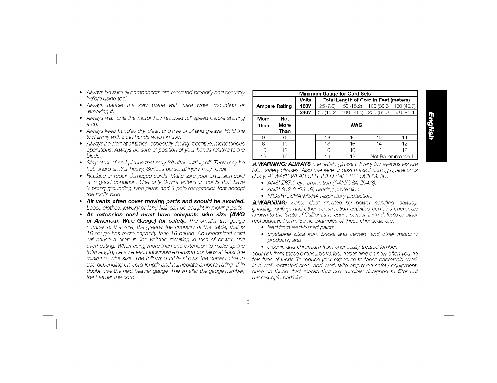
• An extension cord must have adequate wire size (AWG
or American Wire Gauge) for safety. The smaller the gauge
number of the wire, the greater the capacity of the cable, that is
16 gauge has more capacity than 18 gauge. An undersized cord
will cause a drop in line voltage resulting in loss of power and
overheating. When using more than one extension to make up the
total length, be sure each individual extension contains at least the
minimum wire size. The following table shows the correct size to
use depending on cord length and nameplate ampere rating. If in
doubt, use the next heavier gauge. The smaller the gauge number,
the heavier the cord.
Minimum Gauge for Cord Sets
Ampere Rating
More Not
Than More AWG
Than
0 6 18 16 16 14
6 10 18 16 14 12
10 12 16 16 14 12
12 16 14 12 Not Recommended
Volts Total Length of Cord in Feet (meters)
120V 25 (7.6) 50 (15.2) 100 (30.5)_ 150 (45.7)
240V 50 (15.2) 100 (30.5) 200 (61.0)| 300 (91.4)
A WARNING: ALWAYS use safety glasses. Everyday eyeglasses are
NOT safety glasses. Also use face or dust mask if cutting operation is
dusty, ALWAYS WEAR CERTIFIED SAFETY EQUIPMENT_
• ANSI Z87.1 eye protection (CAN/CSA Z94.3),
• ANSI $12.6 ($3. 19) hearing protection,
• NIOSH/OSHA/MSHA respiratory protection.
i_WARNING: Some dust created by power sanding, sawing,
grinding, drilling, and other construction activities contains chemicals
known to the State of California to cause cancer, birth defects or other
reproductive harm. Some examples of these chemicals are:
• lead from lead-based paints,
• crystalline silica from bricks and cement and other masonry
products, and
• arsenic and chromium from chemically-treated lumber.
Yourrisk from these exposures varies, depending on how often you do
this type of work. To reduce your exposure to these chemicals: work
in a well ventilated area, and work with approved safety equipment,
such as those dust masks that are specially designed to filter out
microscopic particles.
Page 7
• Avoid prolonged contact with dust from power sanding,
sawing, grinding, drilling, and other construction activities.
Wear protective clothing and wash exposed areas with soap
and water. Allowing dust to get into your mouth, eyes, or lay on
the skin may promote absorption of harmful chemicals.
_ WARNING: Use of this tool can generate and/or disperse dust,
which may cause serious and permanent respiratory or other injury.
Always use NIOSH/OSHA approved respiratory protection appropriate
for the dust exposure. Direct particles away from face and body.
A WARNING: Always wear proper personal hearing protection
that conforms to ANSI $12.6 ($3.19) during use. Under some
conditions and duration of use, noise from this product may contribute
to hearing loss.
• The label on your tool may include the following symbols. The
symbols and their definitions are as follows:
V........... volts
Hz......... hertz
min .......minutes "_ .....
- -- ....direct current _ .....
(_)......... Class I Construction no ......
(grounded) _ ......
[] ......... Class II Construction A .......
(double insulated) BPM..
.../min.. per minute RPM..
IPM .......impacts per minute sfpm..
A........ amperes
W....... watts
alternating current
alternating or direct current
no load speed
earthing terminal
safety alert symbol
beats per minute
revolutions per minute
surface feet per minute
SAVE THESE INSTRUCTIONS FOR
FUTURE USE
Motor
Be sure your power supply agrees with the nameplate marking.
Voltage decrease of more than 10% will cause loss of power and
overheating. DEWALT tools are factory tested; if this tool does not
operate, check power supply.
FIG.1 B
A C
L E
D
G
H
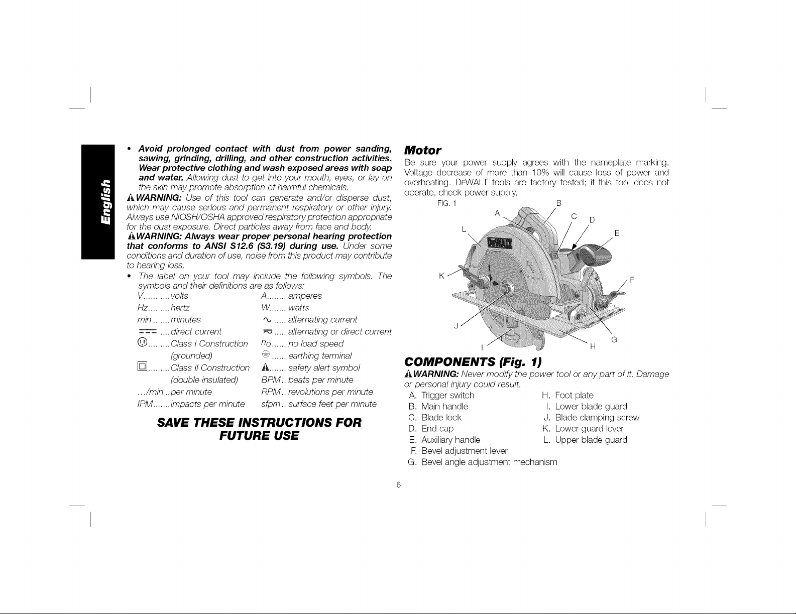
COMPONENTS (Fig. 1)
i_,WARNING: Never modify the power tool or any part of it. Damage
or personal injury could result.
A. Trigger switch
B. Main handle
C. Blade lock
D. End cap
E. Auxiliary handle
F. Bevel adjustment lever
G. Bevel angle adjustment mechanism
H. Foot plate
I. Lower blade guard
J. Blade clamping screw
K. Lower guard lever
L. Upper blade guard
Page 8
INTENDED USE
These heavy-duty circular saws are designed for professional wood
cutting applications. DO NOT use water feed attachments with this
saw. DO NOT use abrasive wheels or blades. DO NOT use under wet
conditions or in presence of flammable liquids or gases.
These heavy-duty saws are professional power tools. DO NOT let
children come into contact with the tool. Supervision is required when
inexperienced operators use this tool.
ADJUSTMENTS
Changing Blades
_WARNING: To reduce the risk of injury, turn unit off and
disconnect it from power source before installing and removing
accessories, before adjusting or when making repairs. An
accidental start-up can cause injury.
FIG. 3
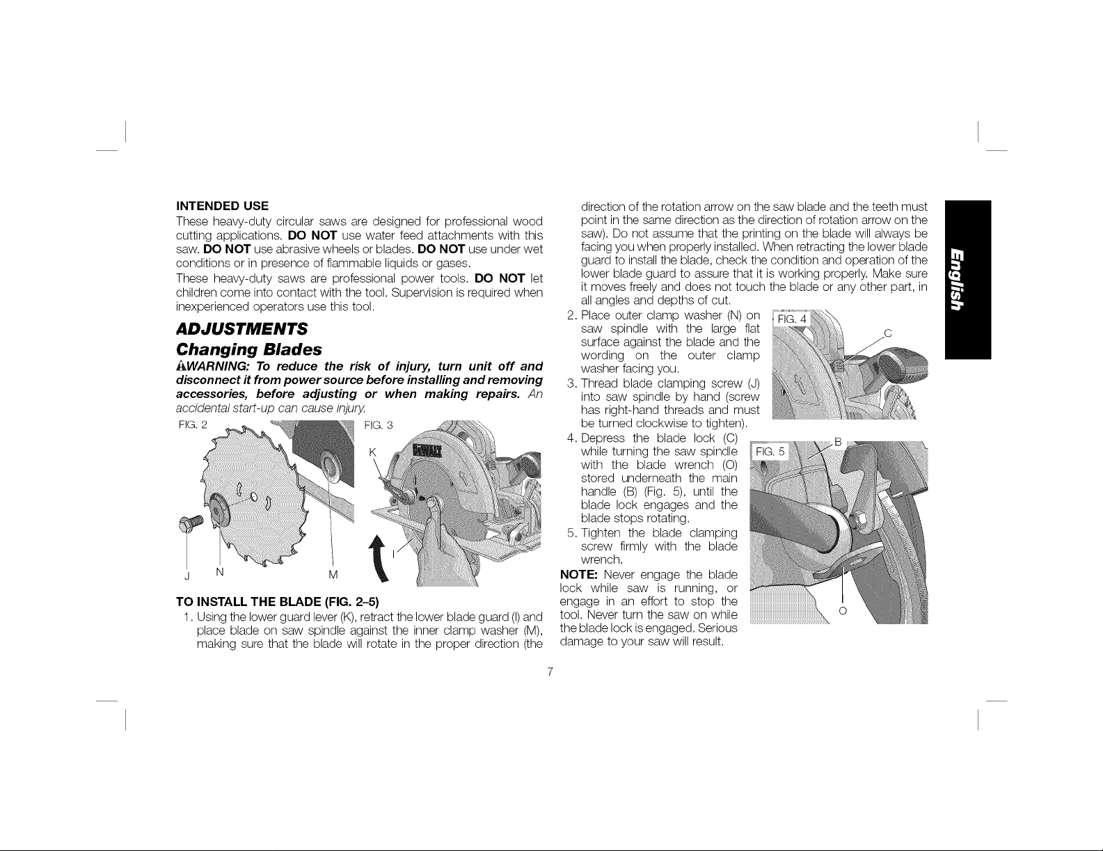
TO INSTALL THE BLADE (FIG. 2-5)
1. Using the lower guard lever(K),retract the lower blade guard (I)and
place blade on saw spindle against the inner clamp washer (M),
making sure that the blade will rotate in the proper direction (the
direction of the rotation arrow on the saw blade and the teeth must
point in the same direction as the direction of rotation arrow on the
saw). Do not assume that the printing on the blade will always be
facing you when properly installed. When retracting the lower blade
guard to install the blade, check the condition and operation of the
lower blade guard to assure that it is working properly. Make sure
it moves freely and does not touch the blade or any other part, in
all angles and depths of cut.
2. Place outer clamp washer (N) on FIG.4
saw spindle with the large flat
surface against the blade and the
wording on the outer clamp
washer facing you.
3. Thread blade clamping screw (J)
into saw spindle by hand (screw
has right-hand threads and must
be turned clockwise to tighten).
4. Depress the blade lock (C)
while turning the saw spindle
with the blade wrench (O)
stored underneath the main
handle (B) (Fig. 5), until the
blade lock engages and the
blade stops rotating.
5. Tighten the blade clamping
screw firmly with the blade
wrench.
NOTE: Never engage the blade
lock while saw is running, or
engage in an effort to stop the
tool. Never turn the saw on while
the blade lock isengaged. Serious
damage to your saw will result.
Page 9
TO REPLACE THE BLADE (FIG. 2, 4, 5)
1. To loosen the blade clamping screw (J), depress the blade lock
(C) and turn the saw spindle with the blade wrench (O), stored
underneath the main handle (B), until the blade lock engages
and the blade stops rotating. With the blade lock engaged,
turn the blade clamping screw counterclockwise with the blade
wrench (screw has right-hand threads and must be turned
counterclockwise to loosen).
2. Remove the blade clamping screw (J)and outer clamp washer (N).
Remove old blade.
3. Clean any sawdust that may have accumulated in the guard or
clamp washer area and check the condition and operation of the
lower blade guard as previously outlined. Do not lubricate this area.
4. Select the proper blade for theapplication (referto Recommended
Blade Types under Blades). Always use blades that are the
correct size (diameter) with the proper size and shape center hole
for mounting on tile saw spindle. Always assure that tile maximum
recommended speed (rpm) on the saw blade meets or exceeds
the speed (rpm) of the saw.
5. Follow steps 1through 5 under To Installthe Blade, making sure
that the blade will rotate in the proper direction.
LOWER BLADE GUARD
_WARNING: The lower blade guard is a safety feature which
reduces the risk of serious personal injury. Never use the saw if
the lower guard is missing, damaged, misassembled or not
working properly. Do not rely on the lower blade guard to
protect you under all circumstances. Your safety depends on
following all warnings and precautions as well as proper
operation of the saw. Check lower guard for proper closing
before each use as outlined in Additional Safety Rules for
Circular Saws. If the lower blade guard is missing or not
working properly, have the saw serviced before using. To
assure product safety and reliability, repair, maintenance and
adjustment should be performed by an authorized service
center or other qualified service organization, always using
identical replacement parts.
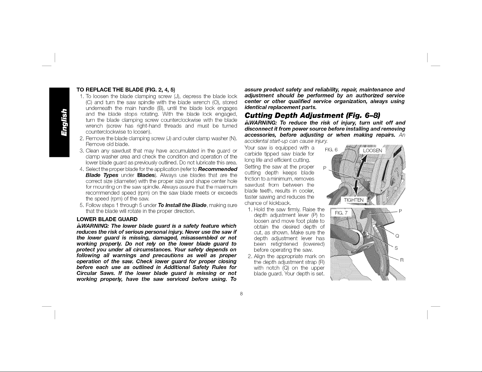
Cutting Depth Adjustment (Fig. 6-8)
_WARNING: To reduce the risk of injury, turn unit off and
disconnect it from power source before installing and removing
accessories, before adjusting or when making repairs. An
accidental start-up can cause injury.
Your saw is equipped with a FIG.6
carbide tipped saw blade for
long lifeand efficient cutting.
Setting the saw at the proper p
cutting depth keeps blade
friction to a minimum, removes
sawdust from between the
blade teeth, results in cooler,
faster sawing and reduces the
chance of kickback.
1. Hold the saw firmly. Raise the
depth adjustment lever (P) to
loosen and move foot plate to
obtain the desired depth of
cut, as shown. Make sure the
depth adjustment lever has
been retightened (lowered)
before operating the saw.
2. Align the appropriate mark on
the depth adjustment strap (R)
with notch (Q) on the upper
blade guard. Your depth is set.
Page 10
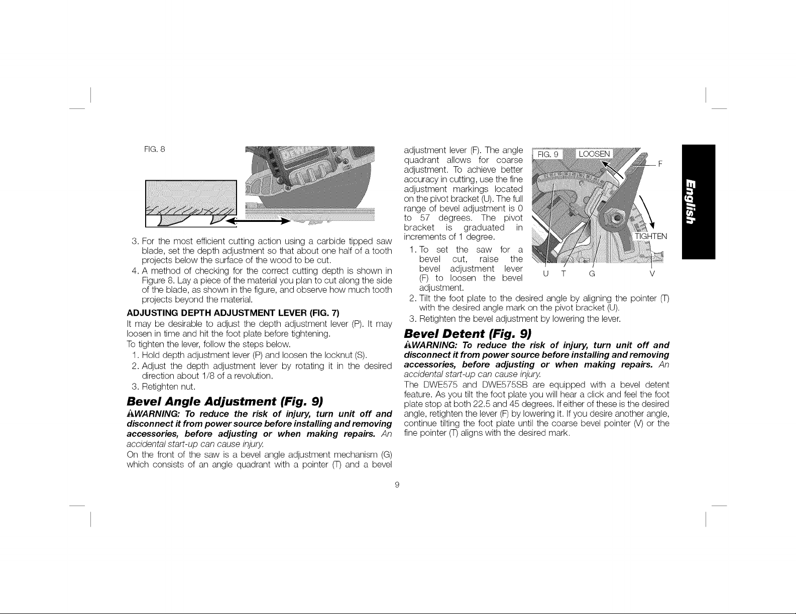
FIG.8
3. For the most efficient cutting action using a carbide tipped saw
blade, set the depth adjustment so that about one half of a tooth
projects below the surface of the wood to be cut.
4. A method of checking for the correct cutting depth is shown in
Figure 8. Lay a piece of the material you plan to cut along the side
of the blade, as shown in the figure, and observe how much tooth
projects beyond the material.
ADJUSTING DEPTH ADJUSTMENT LEVER (FIG. 7)
It may be desirable to adjust the depth adjustment lever (P). It may
loosen in time and hit the foot plate before tightening.
Totighten the lever, follow the steps below.
1. Hold depth adjustment lever (P) and loosen the Iocknut (S).
2. Adjust the depth adjustment lever by rotating it in the desired
direction about 1/8 of a revolution.
3. Retighten nut.
Bevel Angle Adjustment (Fig. 9)
AWARNING: To reduce the risk of injury, turn unit off and
disconnect it from power source before installing and removing
accessories, before adjusting or when making repairs. An
accidental start-up can cause injury.
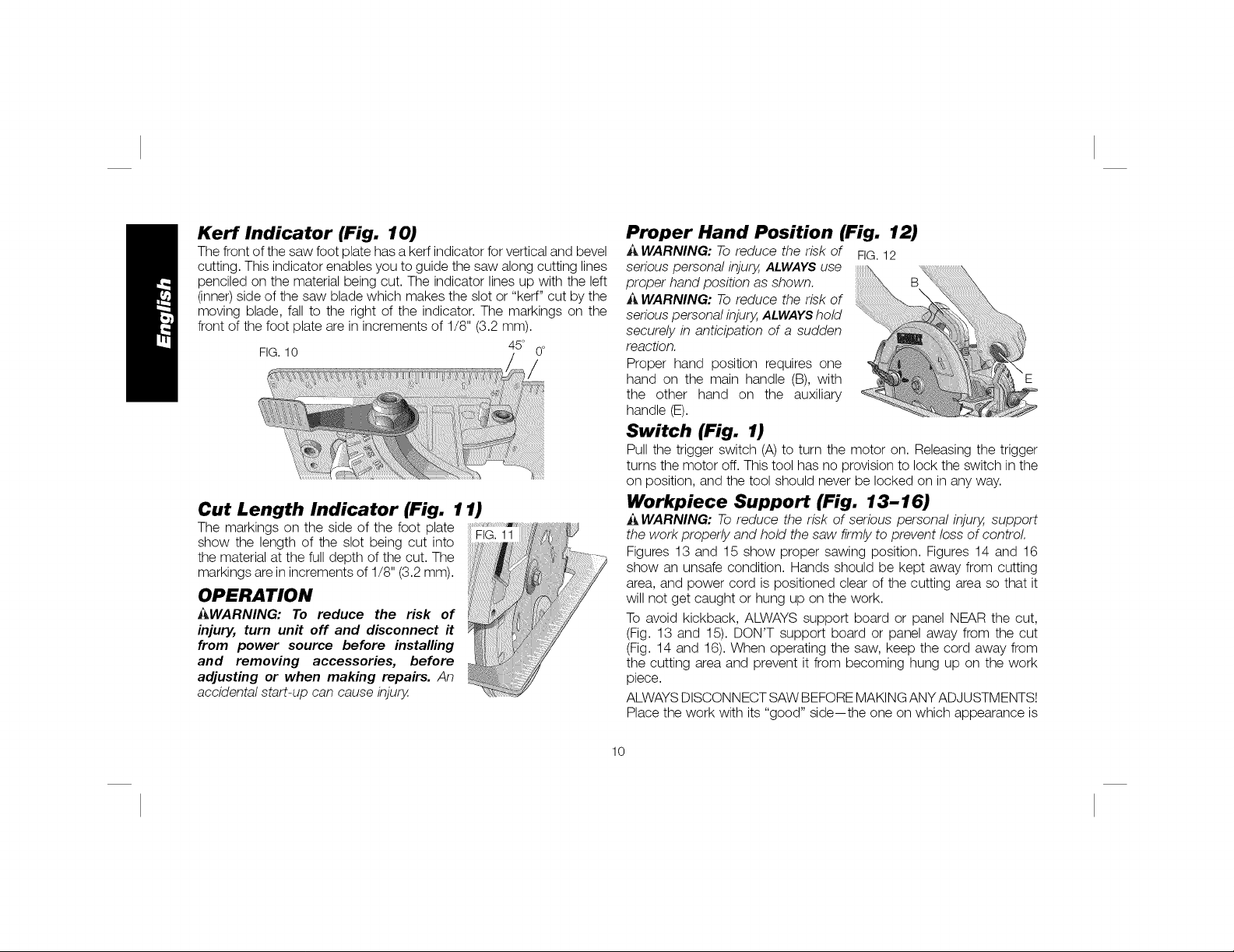
On the front of the saw is a bevel angle adjustment mechanism (G)
which consists of an angle quadrant with a pointer (T) and a bevel
adjustment lever (F).The angle
quadrant allows for coarse F
adjustment. To achieve better
accuracy in cutting, use the fine
adjustment markings located
on the pivot bracket (U).The full
range of bevel adjustment is 0
to 57 degrees. The pivot
bracket is graduated in
increments of 1 degree. TIGHTEN
1.To set the saw for a
bevel cut, raise the
bevel adjustment lever
(F) to loosen the bevel U T G V
adjustment.
2. Tilt the foot plate to the desired angle by aligning the pointer (T)
with the desired angle mark on the pivot bracket (U).
3. Retighten the bevel adjustment by lowering the lever.
Bevel Detent (Fig. 9)
i_WARNING: To reduce the risk of injury, turn unit off and
disconnect it from power source before installing and removing
accessories, before adjusting or when making repairs. An
accidental start-up can cause injury.
The DWE575 and DWE575SB are equipped with a bevel detent
feature. As you tilt the foot plate you will hear a click and feel the foot
plate stop at both 22.5 and 45 degrees. Ifeither of these is the desired
angle, retighten the lever (F) by lowering it. Ifyou desire another angle,
continue tilting the foot plate until the coarse bevel pointer (V) or the
fine pointer (T)aligns with the desired mark.
Page 11
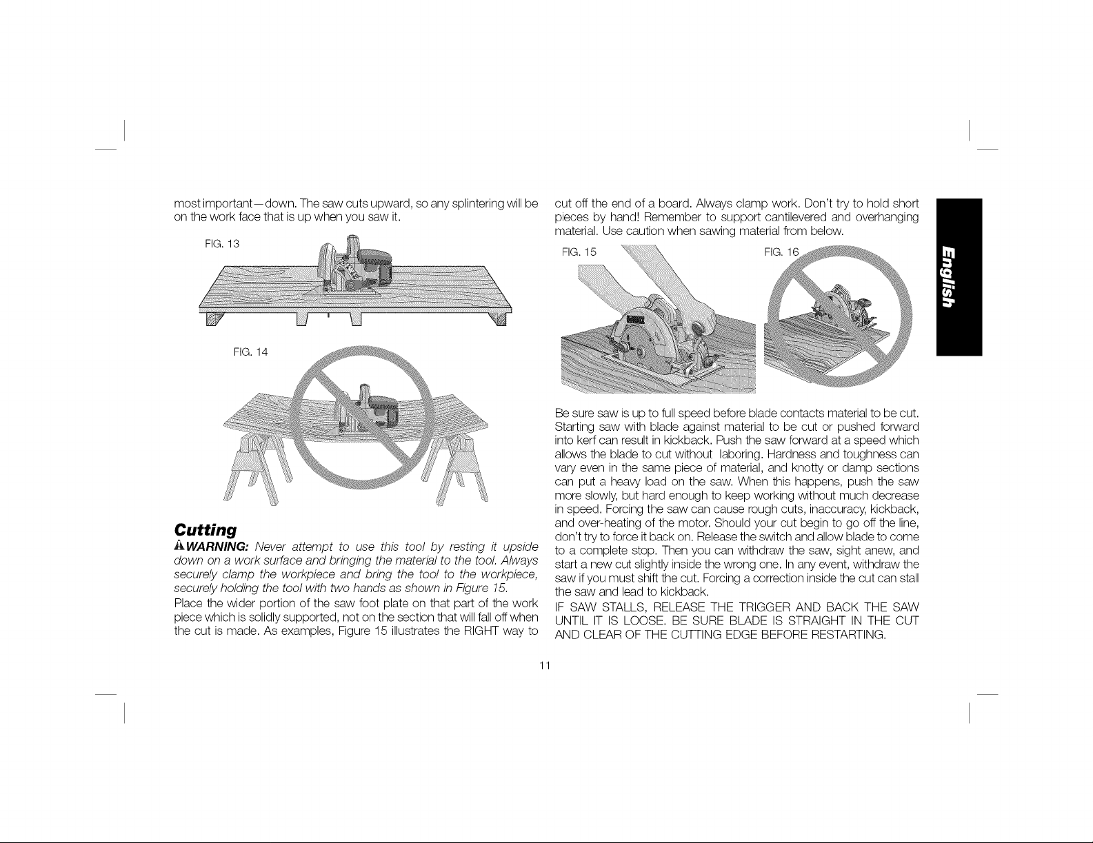
Kerf Indicator (Fig. 10)
The front of the saw foot plate has a kerf indicator for vertical and bevel
cutting. This indicator enables you to guide the saw along cutting lines
penciled on the material being cut. The indicator lines up with the left
(inner)side of the saw blade which makes the slot or "kerf" cut by the
moving blade, fall to the right of the indicator. The markings on the
front of the foot plate are in increments of 1/8" (3.2 mm).
FIG.10 45° 0°
Cut Length Indicator (Fig. 11)
The markings on the side of the foot plate FIG. 11
show the length of the slot being cut into
the material at the full depth of the cut. The
markings are inincrements of 1/8" (3.2 mm).
OPERATION
J_WARNING: To reduce the risk of
injury, turn unff off and disconnect it
from power source before installing
and removing accessories, before
adjusting or when making repairs. An
accidental start-up can cause injury.
Proper Hand Position (Fig. 12)
A WARNING: To reduce the risk of FIG.12
serious personal injury. ALWAYSuse
proper hand position as shown.
i_,WARNING: To reduce the risk of
serious personal injury, ALWAYShold
securely in anticipation of a sudden
reaction.
Proper hand position requires one
hand on the main handle (B), with
the other hand on the auxiliary
handle (E).
Switch (Fig. 1)
Pull the trigger switch (A)to turn the motor on. Releasing the trigger
turns the motor off. This tool has no provision to lock the switch in the
on position, and the tool should never be locked on in any way.
Workpiece Support (Fig. 13-16)
WARNING: Toreduce the risk of serious personal injury, support
the work properly and hold the saw firmly to prevent loss of control
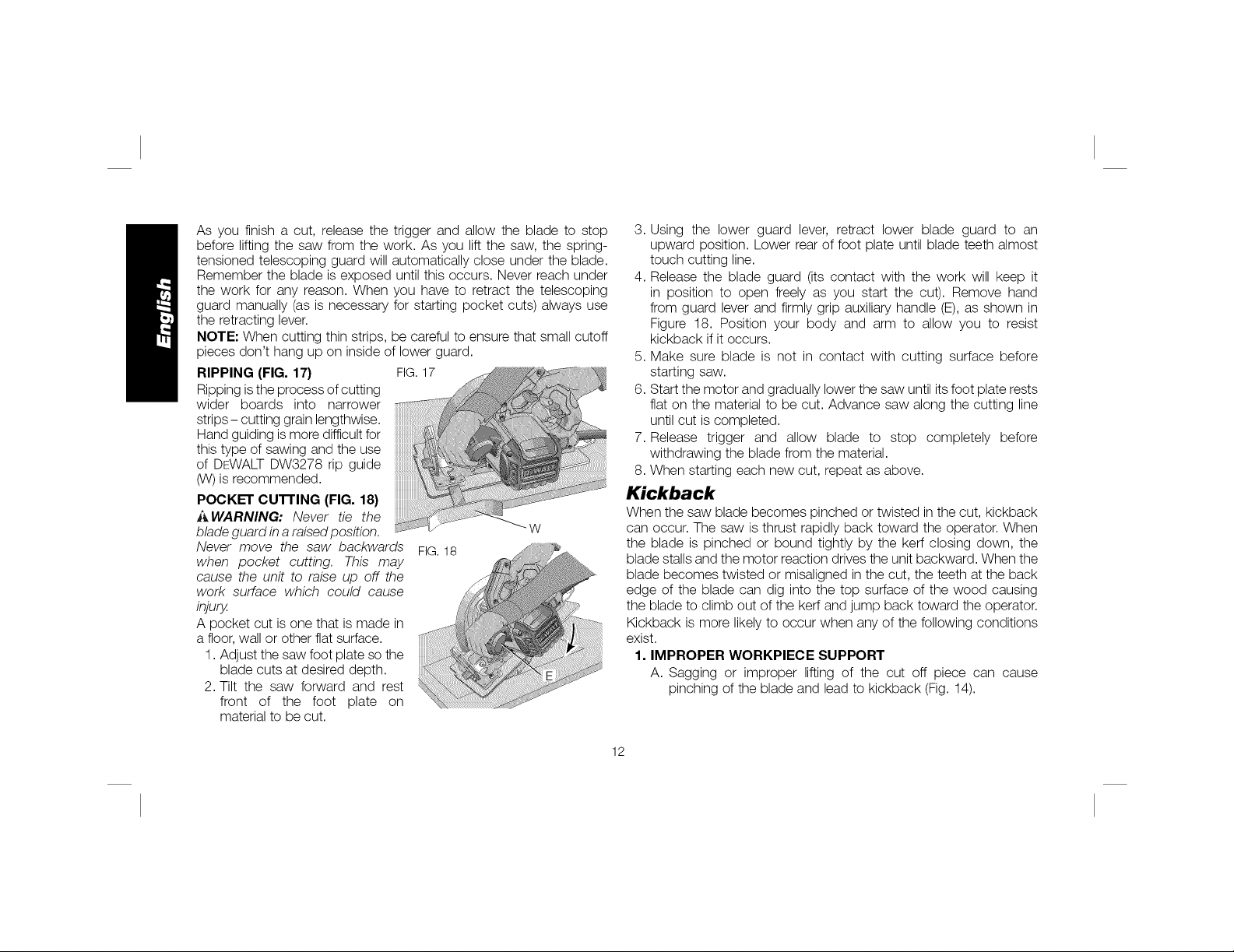
Figures 13 and 15 show proper sawing position. Figures 14 and 16
show an unsafe condition. Hands should be kept away from cutting
area, and power cord is positioned clear of the cutting area so that it
will not get caught or hung up on the work.
To avoid kickback, ALWAYS support board or panel NEAR the cut,
(Fig. 13 and 15). DON'T support board or panel away from the cut
(Fig. 14 and 16). When operating the saw, keep the cord away from
the cutting area and prevent it from becoming hung up on the work
piece.
ALWAYSDISCONN ECTSAW BEFORE MAKING ANY ADJUSTMENTS!
Place the work with its "good" side--the one on which appearance is
10
Page 12
most important--down. The saw cuts upward, so any splintering will be
on the work face that is up when you saw it.
FIG. 13
FIG. 14
Cutting
A WARNING: Never attempt to use this tool by resting it upside
down on a work surface and bringing the material to the tool Always
securely clamp the workpiece and bring the tool to the workpiece,
securely holding the tool with two hands as shown in Figure 15.
Place the wider portion of the saw foot plate on that part of the work
piece which is solidly supported, not on the section that will fall off when
the cut is made. As examples, Figure 15 illustrates the RIGHT way to
cut off the end of a board. Always clamp work. Don't try to hold short
pieces by hand! Remember to support cantilevered and overhanging
material. Use caution when sawing material from below.
FIG.15
Be sure saw is up to fullspeed before blade contacts material to be cut.
Starting saw with blade against material to be cut or pushed forward
into kerf can result in kickback. Push the saw forward at a speed which
allows the blade to cut without laboring. Hardness and toughness can
vary even in the same piece of material, and knotty or damp sections
can put a heavy load on the saw. When this happens, push the saw
more slowly, but hard enough to keep working without much decrease
in speed. Forcing the saw can cause rough cuts, inaccuracy, kickback,
and over-heating of the motor. Should your cut begin to go off the line,
don't try to force itback on. Release the switch and allow blade to come
to a complete stop. Then you can withdraw the saw, sight anew, and
start a new cut slightly inside the wrong one. Inany event, withdraw the
saw ifyou must shift the cut. Forcing acorrection inside the cut can stall
the saw and lead to kickback.
IF SAW STALLS, RELEASE THE TRIGGER AND BACK THE SAW
UNTIL IT IS LOOSE. BE SURE BLADE IS STRAIGHT IN THE CUT
AND CLEAR OF THE CUTTING EDGE BEFORE RESTARTING.
11
Page 13
As you finish a cut, release the trigger and allow the blade to stop
before lifting the saw from the work. As you lift the saw, the spring-
tensioned telescoping guard will automatically close under the blade.
Remember the blade is exposed until this occurs. Never reach under
the work for any reason. When you have to retract the telescoping
guard manually (as is necessary for starting pocket cuts) always use
the retracting lever.
NOTE" When cutting thin strips, be careful to ensure that small cutoff
pieces don't hang up on inside of lower guard.
RIPPING (FIG. 17)
FIG. 17
Ripping isthe process of cutting
wider boards into narrower
strips-cutting grain lengthwise.
Hand guiding is more difficult for
this type of sawing and the use
of DEWALT DW3278 rip guide
(W) is recommended.
POCKET cu'n'ING (FIG. 18)
_,WARNING: Never tie the
blade guard in a raised position.
Never move the saw backwards
FIG. 18
W
when pocket cutting. This may
cause the unit to raise up off the
work surface which could cause
injury.
A pocket cut is one that is made in
a floor, wall or other flat surface.
1. Adjust the saw foot plate so the
blade cuts at desired depth.
2. Tilt the saw forward and rest
front of the foot plate on
material to be cut.
3. Using the lower guard lever, retract lower blade guard to an
upward position. Lower rear of foot plate until blade teeth almost
touch cutting line.
4. Release the blade guard (its contact with the work will keep it
in position to open freely as you start the cut). Remove hand
from guard lever and firmly grip auxiliary handle (E), as shown in
Figure 18. Position your body and arm to allow you to resist
kickback if it occurs.
5. Make sure blade is not in contact with cutting surface before
starting saw.
6. Start the motor and gradually lower the saw until its foot plate rests
flat on the material to be cut. Advance saw along the cutting line
until cut is completed.
7. Release trigger and allow blade to stop completely before
withdrawing the blade from the material.
8. When starting each new cut, repeat as above.
Kickback
When the saw blade becomes pinched or twisted in the cut, kickback
can occur. The saw is thrust rapidly back toward the operator. When
the blade is pinched or bound tightly by the kerf closing down, the
blade stalls and the motor reaction drives the unit backward. When the
blade becomes twisted or misaligned in the cut, the teeth at the back
edge of the blade can dig into the top surface of the wood causing
the blade to climb out of the kerf and jump back toward the operator.
Kickback is more likely to occur when any of the following conditions
exist.
1. IMPROPER WORKPIECE SUPPORT
A. Sagging or improper lifting of the cut off piece can cause
pinching of the blade and lead to kickback (Fig. 14).
12
Page 14
B. Cutting through material supported at the outer ends only can
cause kickback. As the material weakens it sags, closing down
the kerf and pinching the blade.
C. Cutting off a cantilevered or overhanging piece of material from
the bottom up in a vertical direction can cause kickback. The
falling cut off piece can pinch the blade.
D. Cutting off long narrow strips (asinripping) can cause kickback.
The cut off strip can sag or twist closing the kerf and pinching
the blade.
E. Snagging the lower guard on a surface below the material
being cut momentarily reduces operator control. The saw can
lift partially out of the cut increasing the chance of blade twist.
2. IMPROPER DEPTH OF CUT SE'rI'ING ON SAW
To make the most efficient cut, the blade should protrude only far
enough to expose 1/2 of a tooth as shown in Figure 9. This allows
the foot plate to support the blade and minimizes twisting and
pinching in the material. Refer to Cutting Depth Adjustment.
3. BLADE TWISTING (MISALIGNMENT IN CUT)
A. Pushing harder to cut through a knot, a nail, or a hard grain
area can cause the blade to twist.
B. Trying to turn the saw in the cut (trying to get back on the
marked line)can cause blade twist.
C. Over-reaching or operating the saw with poor body control (out
of balance), can result in twisting the blade.
D. Changing hand grip or body position while cutting can result in
blade twist.
E. Backing up the saw to clear blade can lead to twist if it is not
done carefully.
4. MATERIALS THAT REQUIRE EXTRA ATTENTION
A. Wet lumber
B. Green lumber (material freshly cut or not kiln dried)
C. Pressure treated lumber (material treated with preservatives or
anti-rot chemicals)
5. USE OF DULL OR DIRTY BLADES
Dull blades cause increased loading of the saw. To compensate,
an operator will usually push harder which further loads the unit
and promotes twisting of the blade in the kerf. Worn blades may
also have insufficient body clearance which increases the chance
of binding and increased loading.
6. LIFTING THE SAW WHEN MAKING BEVEL CUTS
Bevel cuts require special operator attention to proper cutting
techniques - especially guidance of the saw. Both blade angle to
the foot plate and greater blade surface in the material increase the
chance for binding and misalignment (twist) to occur.
7. RESTARTING A CUT WITH THE BLADE TEETH JAMMED
AGAINST THE MATERIAL
The saw should be brought up to full operating speed before
starting a cut or restarting a cut after the unit has been stopped
with the blade in the kerf. Failure to do so can cause stalling and
kickback.
Any other conditions which could result in pinching, binding, twisting,
or misalignment of the blade could cause kickback. Refer to
Additional Safety Instructions and Operation for procedures and
techniques that will minimize the occurrence of kickback.
MAINTENANCE
_ WARNING: To reduce the risk of injury, turn unit off and
disconnect it from power source before installing and removing
accessories, before adjusting or when making repairs. An
accidental start-up can cause injury.
13
Page 15
Cleaning
_ WARNING: Blow dirt and dust out of all air vents with clean, dry air
at least once a week. To minimize the risk of eye injury, always wear
ANSI Z87.1 approved eye protection when performing this.
_ WARNING: Never use solvents or other harsh chemicals for cleaning
the non-metallic parts of the tool These chemicals may weaken the
plastic materials used in these parts. Use a cloth dampened only with
water and mild soap. Never let any liquid get inside the tool," never
immerse any part of the tool into a liquid.
Lubrication
Self lubricating ball and roller bearings are used in the tool and
relubrication is not required. However, it is recommended that, once
a year, you take or send the tool to a service center for a thorough
cleaning, inspection and lubrication of the gear case.
Electric Brake (DWE5 75SB)
Your saw has an automatic electric brake which is designed to stop
the blade from coasting in about two seconds, after you release the
trigger switch. It is useful when making certain cuts in wood where a
coasting blade would result in a wide, imprecise cut.
Occasionally, the brake will not function properly and won't stop the
saw in the 2 seconds discussed above. Ifthis condition persists, turn
the saw on and off four or five times. If the brake still does not stop
the blade in about 2 seconds, the problem may be worn brushes.
Have the brushes replaced at a DEWALT authorized service center.
Repairs
To assure product SAFETY and RELIABILITY, repairs, maintenance
and adjustment should be performed by a DFWALT factory service
center, a DEWALTauthorized service center or other qualified service
personnel. Always use identical replacement parts. (Refer to Brushes
for brush replacement information.)
Brushes (Fig. 19)
WARNING: To reduce the risk of injury, turn unit off and
disconnect it from power source before installing and removing
accessories, before adjusting or when making repairs. An
accidental start-up can cause injury,
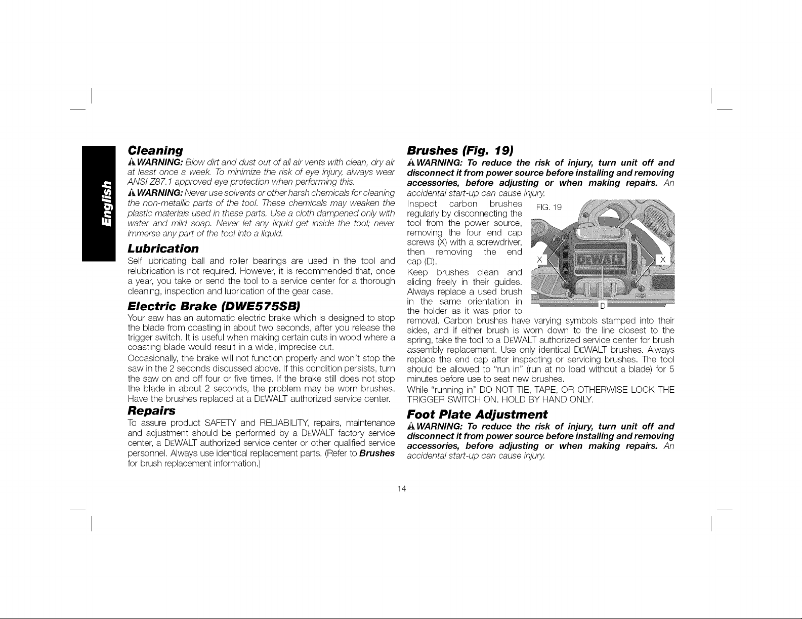
Inspect carbon brushes FIG.19
regularly by disconnecting the
tool from the power source,
removing the four end cap
screws (X)with a screwdriver,
then removing the end X_
cap (D).
Keep brushes clean and
sliding freely in their guides.
Always replace a used brush
in the same orientation in ................................D ....
the holder as it was prior to
removal. Carbon brushes have varying symbols stamped into their
sides, and if either brush is worn down to the line closest to the
spring, take the tool to a DEWALT authorized service center for brush
assembly replacement. Use only identical DEWALT brushes. Always
replace the end cap after inspecting or servicing brushes. The tool
should be allowed to "run in" (run at no load without a blade) for 5
minutes before use to seat new brushes.
While "running in" DO NOT TIE, TAPE, OR OTHERWISE LOCK THE
TRIGGER SWITCH ON. HOLD BY HAND ONLY.
Foot Plate Adjustment
A WARNING: To reduce the risk of injury, turn unit off and
disconnect it from power source before installing and removing
accessories, before adjusting or when making repairs. An
accidental start-up can cause injury,
14
Page 16
Your hot plate has been factory set to assure that the blade is
perpendicular to the foot plate. If after extended use you need to
re-align the blade, follow the directions below:
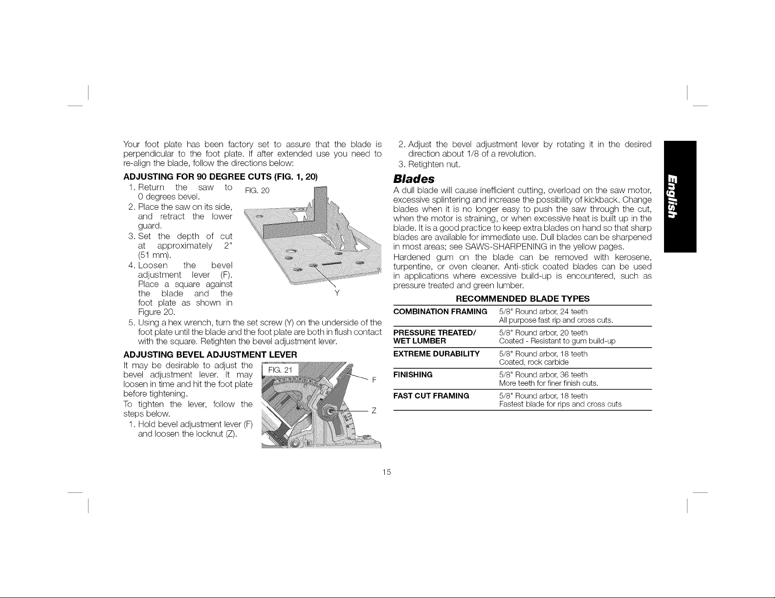
ADJUSTING FOR 90 DEGREE CUTS (FIG. 1, 20)
1. Return the saw to FIG.20
0 degrees bevel.
2. Place the saw on its side, _.:_
and retract the lower ....
guard.
3. Set the depth of cut
at approximately 2"
(51 mm).
4. Loosen the bevel
adjustment lever (F).
Place a square against ',
the blade and the Y
foot plate as shown in
Figure 20.
5. Using a hex wrench, turn the set screw (Y)on the underside of the
foot plate until the blade and the foot plate are both in flush contact
with the square. Retighten the bevel adjustment lever.
ADJUSTING BEVEL ADJUSTMENT LEVER
It may be desirable to adjust the
bevel adjustment lever. It may
loosen in time and hit the foot plate
before tightening.
To tighten the lever, follow the
steps below.
Z
1. Hold bevel adjustment lever (F)
and loosen the Iocknut (Z).
2. Adjust the bevel adjustment lever by rotating it in the desired
direction about 1/8 of a revolution.
3. Retighten nut.
Blades
A dull blade will cause inefficient cutting, overload on the saw motor,
excessive splintering and increase the possibility of kickback. Change
blades when it is no longer easy to push the saw through the cut,
when the motor is straining, or when excessive heat is built up in the
blade. It is a good practice to keep extra blades on hand so that sharp
blades are available for immediate use. Dull blades can be sharpened
in most areas; see SAWS-SHARPENING in the yellow pages.
Hardened gum on the blade can be removed with kerosene,
turpentine, or oven cleaner. Anti-stick coated blades can be used
in applications where excessive build-up is encountered, such as
pressure treated and green lumber.
RECOMMENDED BLADE TYPES
COMBINATION FRAMING 5/8" Round arbor, 24 teeth
All purpose fast rip and cross cuts.
PRESSURE TREATED/ 5/8" Round arbor, 20 teeth
WET LUMBER Coated - Resistant to gum build-up
EXTREME DURABILITY 5/8" Round arbor, 18 teeth
Coated, rock carbide
FINISHING 5/8" Round arbor, 36 teeth
More teeth for finer finish cuts.
FAST CUT FRAMING 5/8" Round arbor, 18 teeth
Fastest blade for rips and cross cuts
15
Page 17
Accessories
•_ WARNING: Since accessories, other than those offered by DEWALT,
have not been tested with this product, use of such accessories with
this tool could be hazardous. Toreduce the risk of injury, only DEWALT,
recommended accessories should be used with this product.
Recommended accessories for use with your tool are available at
extra cost from your local dealer or authorized service center. If you
need assistance in locating any accessory, please contact DEWALT
Industrial Tool Co., 701 East Joppa Road, Baltimore, MD 21286, call
1-800-4-DEWALT (1-800-433-9258) or visit our website www.dewalt.
com.
DO NOT USE WATER FEED ATTACHMENTS WITH THIS SAW.
VISUALLY EXAMINE CARBIDE BLADES BEFORE USE. REPLACE IF
DAMAGED.
Three Year Limited Warranty
DEWALTwill repair,without charge, any defects due to faulty materials
or workmanship for three years from the date of purchase. This
warranty does not cover part failure due to normal wear or tool abuse.
For further detail of warranty coverage and warranty repair information,
visit www.dewalt.com or call 1-800-4-DEWALT (1-800-433-9258).
This warranty does not apply to accessories or damage caused where
repairs have been made or attempted by others. This warranty gives
you specific legal rights and you may have other rights which vary in
certain states or provinces.
In addition to the warranty, DEWALT tools are covered by our:
1 YEAR FREE SERVICE
DEWALT will maintain the tool and replace worn parts caused by
normal use, for free, any time during the first year after purchase.
90 DAY MONEY BACK GUARANTEE
If you are not completely satisfied with the performance of your
DFWALT Power Tool, Laser, or Nailer for any reason, you can return it
within 90 days from the date of purchase with a receipt for a full refund
- no questions asked.
LATIN AMERICA: This warranty does not apply to products sold in
Latin America. For products sold in Latin America, see country specific
warranty information contained either in the packaging, call the local
company or see website for warranty information.
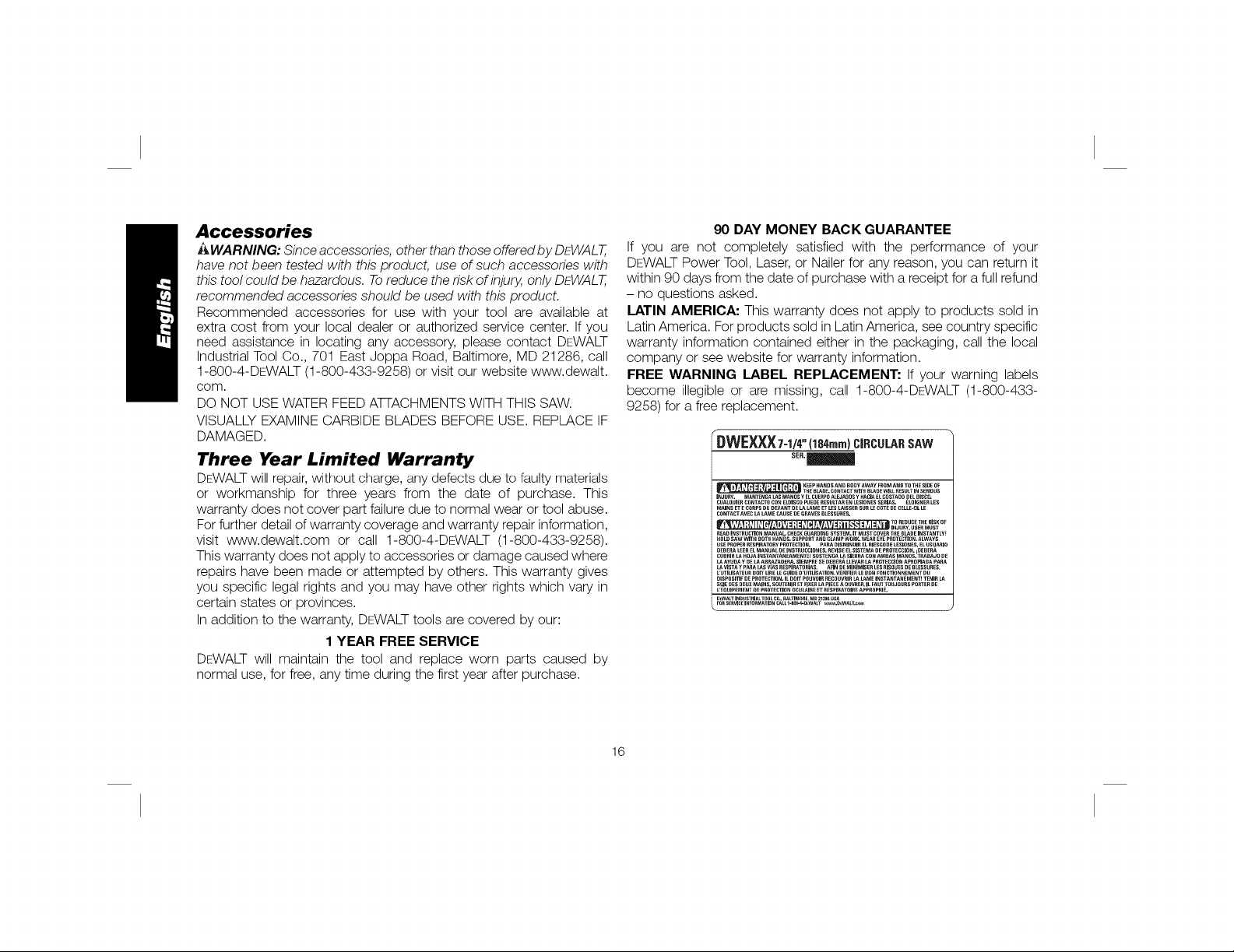
FREE WARNING LABEL REPLACEMENT: If your warning labels
become illegible or are missing, call 1-800-4-DEWALT (1-800-433-
9258) for a free replacement.
r
DWEXXX7-1/4"('t84,.,.)CIRCULARSAW
$ER._
__'HE BL_J]E. COI_TACTWITH J]LAOEWILLRESULTIN SEBIOUS
INJURY. M,O.NTENGAL_'.SM._NOSyE_.CUERPO._LEJAOOSy HACIAELCOSTAO0pELOISCO.
CUALOUlERCONTACTOCONELDISCOpUEDECESUI.TARENLESIONESSERIAS. ELOIGNECLES
MAINSETECORPSDUDEVANTDELAI.AMEETI.ESI.AlSSERSUCLECOTEDECELLE-CZLE
CONTACT.e.VECU_LAMEC.e.USE_EGRAVESBLESSU._ES.
! _' L ' ! _ _ '_ ' '|| IJ INJUI_'t.USERMUST
R_DINSTRUCTeONMANUALCHECKGUAROI_GSYSTEM.ITMUSTCOVERTffEBLADEINSTANTL't_
HOLDSAWwrrH80THHANOS.SUPPO'_'rANOC_.AM_'WOC_WEAnEYEPROTECTIOn.ALWAYS
USEPI_OP_€RESPIRA'rORyPROTECTIOPJ.PA_ DISMINUIRELRIESGO0_LESIO_S,ELUS_ARIO
D_B_AL_:E_ELMANUALDEINS'T_U¢CIO_ES.*._VlSEELSlST_I_,:,DEP_OT_:CCIO_._O_B_._A
CtlBI_I__.AHOJAIt_s_rANTA_EAME_'_SOSTE_AL_SlE_._ACO_AMB_S_ANDS.T_}_A._OI_E
A'/U_AY_ _ AB_Z_ _A. SlEMP_ES__B_'_AL_.EVA_Le.P'_OTECCIO_'JAP_OP_OAPA_
Le.VlSTA'CPA_U_SV_ESPI_._.TORIAS.t,_NI)EMINMSEeL_S_IS_U_SDEe_ESSU_ES.
LrUTILISATEURDOlT_.I_E1.2_UIDED'UTP.lSATION.VECIFIER_.E80NFONCTIO_NEr,_ENTOU
DISPOSI_ZFDEP_OTECTION.ILDon"POUVOIR_E_:OUy'_ICLAI.AMEINSTA_TAN_MENT_TENIRLA
SClEDESDEUXMAIMS.SOU'rENIRET_P(ERL_PIECEAOUVRE_.ILFAUT:rOUJOURSPO_TERDE
L'EOUI_EME_TOEP_O'r_C_ONOCUL_I_EET_ESPI_A'rOIR_APPI_OPRIE.
,_WA_TIP_rlUST_J_.TOOL_r_.._._.TIMO_E.M0_. US_
KEEPHANDS AND BOt]YAWAY FROMAND TO THESIDE OF
"tOREDUCE_ _IS_O_
16
Page 18
D_finitions : lignes directrices en
mati_re de s_curit_
Les definitions ci-dessous decrivent le niveau de danger pour
chaque mot-indicateur employe. Lire le mode d'emploi et
porter une attention particuliere a.ces symboles.
_DANGER : indique une situation dangereuse imminente
qui, si elle n'est pas evitee, entraTnera la mort ou des
blessures graves.
_AVERTISSEMENT : indique une situation potentiellement
dangereuse qui, si elle n' est pas evitee, pourrait entra_ner la
mort ou des blessures graves.
AATTENTION : indique une situation potentiellement
dangereuse qui, si elle n'est pas evitee, pourrait entra_ner
des blessures I_g_res ou modifies.
AVIS : indique une pratique ne posant aucun risque de
dommages corporels mais qui par contre, si rien n'est fait
pour I'eviter, pourrait poser des risques de dommages
materiels.
J
IPOUR TOUTE QUESTION OU REMARQUE AU SUJET DE CET
OUTIL OU DE TOUT AUTRE OUTIL DEWALT, COMPOSEZ LE
NUMFt:ROSANS FRAIS : 1-800-4-DEWALT (1-800-433-9258}.
_ VERTISSEMENT : afin de reduire le risque de blessures, life
le mode d'emploi de I'outil.
Avertissements de s_curit_ g_n_raux
pour les outils _lectriques
s_curit_ et toutes les directives. Le non-respect des
_ AVERTISSEMENT ! Life tousles avertissements de
avertissements et des directives pourrait se solder par un choc
dectrique, un incendie et/ou une blessure grave.
CONSERVER TOUSLES AVERTISSEMENTS
ET TOUTES LES DIRECTIVES POUR UN
USAGE ULTERIEUR
Le terme _ outil dectrique _ cite dans les avertissements se rapporte
votre outil dectrique a alimentation sur secteur (avec ill) ou par piles
(sans fil).
1) S#CURIT# DU LIEU DE TRAVAIL
a) Tenir I'aire de travail propre et bien _clair_e. Les Iieux
encombres ou sombres sont propices aux accidents.
b) Ne pas faire fonctionner d'outils _lectriques clans un
milieu d_flagrant, tel qu'en presence de liquides, de
gaz ou de poussi_res inflammables. Les outi/s e/ectriques
produisent des etincelles qui pourraient enflammer la poussiere
ou les vapeurs.
c) Eloigner les enfants et les personnes a proximit_ pendant
I'utilisation d'un outil _lectrique. Une distraction pourrait en
faire perdre la ma_trisea I'utilisateur.
2) S#CURIT# EN MATIERE D'#LECTRICIT#
a) Les fiches des outils _lectriques doivent correspondre
la prise. Ne jamais modifier la fiche d'aucune faqon.
Ne jamais utiliser de fiche d'adaptation avec un outil
_lectrique mis a la terre. Le risque de choc electrique sera
reduit par I'utilisation de fiches non modifiees correspondant
la prise.
17
Page 19

b) Eviter tout contact physique avec des surfaces mises a la
terre comme des tuyaux, des radiateurs, des cuisini_res
et des r_frig_rateurs. Le risque de choc dectrique est plus
deve si votre corps est mis a la terre.
c) Ne pas exposer les outils _lectriques a la pluie ou
I'humidit_. La penetration de /'eau dans un outi/ dectrique
augmente le risque de choc dectrique.
d) Ne pas utiliser le cordon de fa_on abusive. Ne jamais
utiliser le cordon pour transporter, tirer ou d_brancher un
outil _lectrique. Tenir le cordon _loign_ de la chaleur, de
I'huile, des bords tranchants et des pi_ces mobiles. Les
cordons endommages ou enchev_tres augmentent les risques
de choc dectrique.
e) Pour I'utilisation d'un outil _lectrique a I'ext_rieur, se
servir d'une rallonge convenant a cette application.
L'utilisation d'une ral/onge conque pour I'exterieur reduira les
risques de choc dectrique.
S'il est impossible d'_viter I'utilisation d'un outil _lectrique
clans un endroit humide, brancher I'outil clans une prise
ou sur un circuit d'alimentation dot_s d'un disjoncteur de
fuite a la terre (GFCI). L'utilisation de ce type de disjoncteur
reduit les risques de choc dectrique.
3) SI_CURITI_ PERSONNELLE
a) Etre vigilant, surveiller le travail effectu_ et faire preuve
de jugement Iorsqu'un outil _lectrique est utilis_. Ne
pas utiliser d'outil _lectrique en cas de fatigue ou sous
I'influence de drogues, d'alcool ou de m_dicaments. Un
simple moment d'inattention en utilisant un outil dectrique peut
entra_nerdes blessures corporelles graves.
b) Utiliser des _quipements de protection individuelle.
Toujours porter une protection oculaire. L'uti/isation
d'equipements de protection comme un masque antipoussiere,
des chaussures antiderapantes, un casque de securite ou des
protecteurs auditifs Iorsque la situation le requiert reduira les
risques de blessures corporelles.
c) Emp_cher les d_marrages intempestifs. S'assurer que
I'interrupteur se trouve a la position d'arr_t avant de
relier I'outil a une source d'alimentation et/ou d'ins_rer
un bloc-piles, de ramasser ou de transporter I'outil.
Transporter un outil dectrique alors que le doigt repose sur
I'interrupteur ou brancher un outil dectrique dont I'interrupteur
est a la position de marche risque de provoquer un accident.
d) Retirer toute cl_ de r_glage ou cl_ avant de d_marrer
I'outil. Une c/e ou une c/e de reg/age attachee a une partie
pivotante de I'outil dectrique peut provoquer des blessures
corporelles.
e) Ne pas trop tendre les bras. Conserver son _quilibre en
tout temps. Ce/a permet de mieux ma_triser /'outi/ dectrique
dans les situations imprevues.
S'habiller de mani_re appropri_e. Ne pas porter de
v_tements amples ni de bijoux. Garder les cheveux, les
v_tements et les gants a I'_cart des pi_ces mobiles. Les
v_tements amp/es, /es bijoux ou /es cheveux longs risquent de
rester coinces dans les pieces mobiles.
g) Si des composants sent fournis pour le raccordement de
dispositifs de d_poussi_rage et de ramassage, s'assurer
que ceux-ci sent bien raccord_s et utilis_s. L'uti/isation d'un
dispositif de depoussierage peut reduire les dangers engendres
par les poussieres.
4} UTILISATION ET ENTRETIEN D'UN OUTIL leLECTRIQUE
a) Ne pas forcer un outil _lectrique. Utiliser I'outil _lectrique
appropri_ a I'application. L'outil electrique approprie
effectuera un meilleur travail, de faqon plus sore eta la vitesse
pour laquelle il a ete conqu.
18
Page 20

b) Ne pas utiliser un outil _lectrique dont I'interrupteur
est d_fectueux. Tout outil dectrique dont I'interrupteur est
defectueux est dangereux et doit _tre repare.
c) D_brancher la fiche de la source d'alimentation et/ou du
bloc-piles de I'outil _lectrique avant de faire tout r_glage
ou changement d'accessoire ou avant de ranger I'outil.
Ces mesures preventives reduisent les risques de demarrage
accidentel de I'outil dectrique.
d) Ranger les outils _lectriques hors de la pottle des enfants
et ne permettre a aucune personne n'_tant pas famili_re
avec un outil _lectrique ou son mode d'emploi d'utiliser
cet outil. Les outils dectriques deviennent dangereux entre les
mains d'utilisateurs inexperimentes.
e) Entretien des outils _lectriques. V_rifier si les pi_ces
mobiles sont mal align_es ou coinc_es, si des pi_ces sont
bris_es ou pr_sentent toute autre condition susceptible
de nuire au bon fonctionnement de I'outil _lectrique.
En cas de dommage, faire r_parer I'outil _lectrique
avant toute nouvelle utilisation. Beaucoup d'accidents sont
causes par des outils dectriques mal entretenus.
S'assurer que les outils de coupe sont aiguis_s et
propres. Les outils de coupe bien entretenus et affOtes sont
moins susceptibles de se coincer et sont plus faciles a ma_triser.
g) Utiliser routil _lectrique, /es accessoires, /es forets,
etc. conform_ment aux pr_sentes directives en tenant
compte des conditions de travail et du travail a effectuer.
L'utilisation d'un outil dectrique pour toute operation autre que
celle pour laquelle il a ete conquest dangereuse.
5) RI_PARATION
a) Faire r_parer routil _lectrique par un r_parateur
professionnel en n'utilisant que des pi_ces de rechange
identiques. Cela permettra de maintenir une utilisation
securitaire de I'outil dectrique.
Consignes de s_curit_ propres _ toutes
les scies
a) _DANGER : _loigner les mains des zones et organes
de coupe. Maintenir la deuxi_me main sur la poign_e
auxiliaire ou le boHier du moteur. Lorsque les deux mains
maintiennent la scie, la lame ne peut les couper.
b) N'essayez pas de tenir le dessous de I'ouvrage. Le
protege-lame ne peut pas vous proteger de la lame en dessous
de I'ouvrage.
c) Ajustez la profondeur de coupe a I'_paisseur de I'ouvrage.
Moins d'une dent entiere de lame devrait _tre visible en dessous
de I'ouvrage.
d) Ne tenez jamais clans vos mains ou sur vos genoux un
ouvrage qui est en cours de coupe. Fixez votre ouvrage
sur une plateforme stable. II est important de soutenir
correctement I'ouvrage afin de minimiser I'exposition du corps
la lame, le risque de coincement de la lame ou la perte de
contr61e de I'outil.
e) Tenez I'outil _lectrique par ses surfaces de prehension
isolantes quand vous r_alisez une operation au cours de
laquelle routil de coupe pourraft entrer en contact avec
des c_bles dissimul_s. Le contact avec un fil sous tension
mettra egalement sous tension toutes les pieces metalliques
exposees et donnera un choc dectrique a I'utilisateur de I'outil.
Pendant les coupes de refente, utilisez toujours un guide
de refente ou un guide a bord droft. Ceci augmente toujours
I'exactitude de la coupe et diminue la possibilite de coincement
de la lame.
g) Utilisez toujours des lames dont I'al_sage central est
de la taille et de la forme appropri_es (soft en forme
de diamant, soft en forme de fond). Les lames qui ne
correspondent pas aux pieces de montage de la cie toumeront
19
Page 21

de fagon excentrique, ce qui causera une perte de contr61e de
I'outil.
h) Ne vous servez jamais de rondelles ou de boulons
de lames qui sent endommag_s ou inappropri_s. Les
rondel/es et le boulon de lame ont ete congus specifiquement
pour votre scie dans le but d'assurer une performance optimale
et un fonctionnement sans danger.
Consignes additionnelles de s_curit_
propres _ toutes les scies
CAUSES DES REBONDS ET M#THODES DE PR#VENTION
POUVANT I_TRE UTILIS#ES PAR L'UTILISATEUR :
- Le rebond est une reaction subite (causee par une lame de
scie pincee, coincee ou mal alignee) qui peut entra_ner le
soulevement d'une scie non contr61ee, sa sortie de I'ouvrage et
sa projection en direction de I'utilisateur.
Sila lame estpinc6e ou coinc6e fortement pendant I'abaissement
de la scie, la lame se cale et le moteur reagit en entra_nant
rapidement I'outil vers I'arriere clans la direction de I'operateur.
- Si la lame se tord ou perd son alignement correct au cours
de la coupe, les dents sur le bord arriere de la lame peuvent
entamer la surface superieure du bois, forgant ainsi la lame
sortir du trait de scie eta _sauter _ vers I'arriere en direction de
I'operateur.
Le rebond est la consequence d'une mauvaise utilisation de la scie et/
ou de procedures ou de conditions incorrectes, et il peut _tre evite en
prenant les precautions qui sont decrites ci-dessous :
a) Maintenez fermement la scie avec vos deux mains et
positionnez vos bras de fagon a r_sister aux forces de
rebond. Les forces de rebond peuvent _tre contr61ees par
I'utilisateur quand les precautions appropriees sont prises.
b) En cas de coincement de la lame ou d'interruption d'une
coupe pour une raison quelconque, rel&chez la g&chette
et tenez la scie immobile clans I'ouvrage jusqu'a ce que la
lame se soit immobilis_e compl_tement. Ne tentez jamais
de retirer la scie de I'ouvrage ou de la tirer vers I'arri_re
pendant que la lame est en mouvement, car un rebond
risquerait de se produire. Evaluez la situation et prenez les
mesures correctives necessaires pour diminer la cause du
coincement de la lame.
c) Lorsque vous remettez une scie en marche quand
I'ouvrage est present, centrez la lame de scie clans le traff
de scie et v_rifiez que les dents de la lame ne sent pas
engag_es clans le mat_riau de I'ouvrage. Si /a lame de scie
se coince, elle peut grimper hors de I'ouvrage ou rebondir sur
celui-ci quand la scie est remise en marche.
d) Soutenez les panneaux de grande taille de fagon
minimiser le risque de pincement et de rebond de la
lame. Les panneaux de grande tail/e ont tendance a s'affaisser
sous leur propre poids. Des supports doivent _tre places des
deux c6tes sous le panneau, a proximite de la ligne de coupe et
proximite du rebord du panneau.
e) N'utilisez pas de lame _mouss_e ou endommag_e. Des
lames non aiguisees ou mal installees produisent un trait de scie
etroit qui cause une friction excessive, le coincement de la lame
et un effet de rebond.
Les leviers de r_glage de la profondeur et de I'angle de
coupe de la lame doivent _tre bien serf, s et assujettis
avant de r_aliser une coupe. Une modification du reg/age de
la lame pendant la coupe risque d'entra_ner un coincement et
un rebondissement de lalame.
g) Proc_dez avec une prudence suppl_mentaire quand vous
r_alisez une _,coupe en plong_e _,clans des murs d_ja en
place ou clans des pi_ces sans issue. La lame sail/ante peut
couper des objets, et ceci peut entra_ner un rebond.
2O
Page 22

CONSIGNES DE S#CURIT# RELATIVES AU PROTI-GE-LAME
INF#RIEUR
a) Inspectez le protege-lame inf_rieur avant chaque
utilisation pour vous assurer qu'il se ferme correctement.
Ne fares pas fonctionner la scie si le protege-lame
inf_rieur ne se d_place pas librement et ne se ferme
pas instantan_ment. Ne forcez jamais le protege-lame
inf_rieur clans la position ouverte a I'aide d'un collier de
serrage ou d'une attache. II est possible que le protege-
lame inferieur se torde en cas de chute accidentelle de la
scie. Soulevez le protege-lame inferieur a I'aide de la poignee
retractable et assurez-vous qu'il se deplace sans probleme et
qu'il ne touche pas la lame ou une autre piece, quel que soit
I'angle ou la profondeur de la coupe.
b) V_rifiez le fonctionnement du ressort du protege-lame
inf_rieur. Si le protege-lame inf_rieur et le ressort ne
fonctionnent pas correctement, ils doivent _tre r_par_s
avant I'emploL Le protege-lame inferieur peut parfois ma/
fonctionner a cause de pieces endommagees, d'accumulation
de resine ou de debris.
c) Le protege-lame inf_rieur doit _tre r_tract_ a la main
uniquement a I'occasion de coupes sp_ciales telles que
les _ coupes en plong_e _,ou les _ coupes compos_es _,.
Soulevez le protege-lame inf_rieur a raide la poign_e
r_tractable et rel&chez-le d_s que la lame p_n_tre clans le
mat_riau de I'ouvrage. Pour toute autre operation de sciage,
le protege-lame inferieur doit fonctionner automatiquement.
d) V_rifiez toujours que le protege-lame inf_rieur couvre
la lame avant de placez la scie sur un banc ou sur le
sol Une lame non protegee qui toume librement entra_nerale
mouvement de la scie en marche arriere, ce qui provoquera
la coupe de tout se qui se trouve sur sa trajectoire. Soyez
conscient du temps necessaire a la lame pour s'arr_ter une lois
que la g_chette est rel_chee.
Consignes sp_cifiques additionnelles de
s_curit_ propres aux scies circulaires
AAVERTISSEMENT : ne pas utiliser de meules ou de lames
abrasives.
_4VERTISSEMENT : ne pas utiliser des dispositifs
d'alimentation en eau.
• Utilisez des serres de fixation ou un autre dispositif de
fixation permettant de soutenir et de retenir la piece sur
une plate-forme stable. Tenir lapiece avec la main ou contre son
corps n'est pas suffisamment stable et risque de provoquer une
perte de ma_trisede I'outil.
• Se placer a gauche ou a droite de la lame de scie et non
clans sa trajectoire. L'effet de rebond risque de faire rebondir /a
scie vers /'arriere (consulter/es rubriques Causes des rebonds
et m_thodes de prevention pouvant _tre utilis_es par
I'utilisateur et REBOND).
• Eviter de couper des clous. Inspecter le bois et retirer les
clous presents avant toute coupe.
• La vitesse nominale des accessoires doR _tre _quivalente
ou sup_rieure a celle recommand_e sur r_tiquette
d'avertissement de routil. Une meu/e ou tout autre accessoire
toumant a une vitesse superieure a sa vitesse nominale peut
se desintegrer et poser des risques de dommages corporels.
L'intensite nominale des accessoires utilises doit _tre superieure
la vitesse minimum des outils, indiquee sur la plaque signaletique.
• Avant toute utilisation, s'assurer systematiquement que la scie est
propre.
• En cas de bruit inhabituel ou de fonctionnement anormal, arr_ter
I'utilisation de la scie et la faire verifier.
• S'assurer systematiquement que tousles composants sont
installes correctement et solidement avant toute utilisation de I'outil.
21
Page 23

• Prendre systematiquement des precautions lots de I'installation et
du retrait de la lame de la scie.
• Attendre systematiquement que le moteur tourne a plein regime
avant d'entamer une coupe.
• Maintenir les poignees propres et seches, exemptes d'huile ou
de graisse. Pendant I'utilisation, maintenir fermement I'outil
deux mains.
• Rester constamment vigilant, particulierement lots d'operations
repetitives et monotones. Rester systematiquement conscient de
la position des mains par rapport a la lame.
• Se proteger de la chute de tout rebut pendant la coupe. IIs
pourraient _tre brOlants, coupants et/ou Iourds et poser des
risques de dommages corporels serieux.
• Remplacer ou faire reparer tout cordon endommage. S'assurer
que larallonge est en bon etat. N'utiliser que des rallonges trifilaires
munies de fiches tripolaires, et des prises tripolaires acceptant la
fiche de I'outil.
• Prendre des precautions a proximit_ des _vents, car ils
cachent des pi_ces mobiles. Wtements amp/es, bijoux ou
cheveux longs risquent de rester coinces dans ces pieces mobiles.
• Pour la s_curit_ de I'utilisateur, utiliser une rallonge de
calibre ad_quat (AWG, American Wire Gauge [calibrage
am_ricain normalis_ des ills _lectriques]). Plus le calibre est
petit, et plus sa capacite est grande. Un calibre 16, par exemple,
a une capacite superieure a un calibre 18. L'usage d'une rallonge
de calibre insuffisant causera une chute de tension qui entra_nera
perte de puissance et surchauffe. Si plus d'une rallonge est utilisee
pour obtenir une certaine Iongueur, s'assurer que chaque rallonge
presente au moins le calibre de fil minimum. Le tableau ci-dessous
illustre les calibres a utiliser selon la Iongueur de rallonge et
I'intensite nominale indiquee sur la plaque signaletique. En cas
de doute, utiliser le calibre suivant. Plus le calibre est petit, plus la
rallonge peut supporter de courant.
Calibres minimaux des rallonges
volts Longueur totale de cordon en metres
Intensit_ (en (pieds)
amperes) 120 V 7,6 (25) 15,2 (50) 30,5 (100) I 45,7 (150)
Sup_rieur
o
6
lO
12
Inf_rieur
240 V 15,2 (50) 30,5 (100) 61,0 (200) I 91,4 (300)
AWG
6
10
12
16
18 16 16 14
18 16 14 12
16 16 14 12
14 12 Non recommande
AAVERTISSEMENT : porter SYSTEMATIQUEMENT des lunettes
de protection. Les lunettes courantes NE sont PAS des lunettes de
protection. Utiliser aussi un masque antipoussieres si la decoupe
doit en produire beaucoup. PORTER SYSTEMATIQUEMENT UN
EQUIPEMENT DE SECURITE HOMOLOGUE :
• Protection oculaire ANSI Z87.1 (CAN/CSA Z94.3) ;
• Protection auditive ANSI $12.6 ($3.19) ;
• Protection des voies respiratoires NIOSH/OSHA/MSHA.
,_AVERTISSEMENT : les scies, meules, ponceuses, perceuses
ou autres outils de construction peuvent produire des poussieres
contenant des produits chimiques reconnus par I'Etat califomien pour
causer cancers, malformations congenitales ou _tre nocifs au systeme
reproducteur. Parmi ces produits chimiques, on retrouve :
• Le plomb clans les peintures a base de plomb ;
• La silice cristallisee dans les briques et le ciment, ou autres
produits de maqonnerie ; et
• L'arsenic et le chrome dans le bois ayant subi un traitement
chimique.
22
Page 24

Le risque associe a de telles expositions varie selon la frequence
laquelle on effectue ces travaux. Pour reduire toute exposition aces
produits "travailler dans un endroit bien aere, en utilisant du materiel
de securite homologue, tel un masque antipoussieres specialement
congu pour filtrer les particules microscopiques.
• Limiter toute exposition prolong_e avec les poussi_res
provenant du ponqage, sciage, meulage, perqage ou toute
autre activit_ de construction. Porter des v_tements de
protection et nettoyer a I'eau savonneuse les parties du
corps expos_es. Le fait de laisser la poussiere penetrer clans la
bouche, les yeux ou la peau peut favoriser I'absorption de produits
chimiques dangereux.
i_,AVERTISSEMENT : cet outil peut produire et/ou repandre de
la poussiere susceptible de causer des dommages serieux et
permanents au systeme respiratoire. Utiliser systematiquement un
appareil de protection des voies respiratoires homologue par leNIOSH
ou I'OSHA. Diriger lesparticules dans le sens oppose au visage et au
corps.
_AVERTISSEMENT : pendant I'utilisation, porter
syst_matiquement une protection auditive individuelle
adequate homologu_e ANSI $12.6 ($3.19). Sous certaines
conditions et suivant la duree d'utilisation, le bruit emanant de ce
produit pourrait contribuer a une perte de I'acuite auditive.
• L'etiquette apposee sur votre outil peut inclure les symboles
suivants. Les symboles et leur definition sont indiques ci-apres :
V............. volts
Hz ........... hertz
min ......... minutes
- --. .....courant continu
O_)........... classe I fabrication
(mis a la terre)
[] ........... fabrication classe II
(double isolation)
.../min ....par minute
IPM ......... impacts par minute
sfpm ....... pieds lineaires par minute (plpm)
A ....... amperes
W...... watts
.... courant altematif
.... courant altematif ou
continu
no ..... vitesse a vide
...... borne de terre
_, ...... symbole d'avertissement
BPM.. battements par minute
r/min, tours par minute
CONSERVER CES CONSIGNES POUR
UTILISATION ULTERIEURE
Moteur
S'assurer que le bloc d'alimentation est compatible avec I'inscription
de la plaque signaletique.Une diminution de tension de plus de 10 %
provoquera une perte de puissance et une surchauffe. Les outils
DEWALT sont testes en usine ; si cet outil ne fonctionne pas, verifier
I'alimentation electrique.
23
Page 25

FIG.1
A
B
C D
L
G
H
DESCRIPTION (Fig. 1)
_AVERTISSEMENT : ne jamais modifier I'outil dectrique ni aucun
de ses composants, car il y a risques de dommages corporels ou
materiels,
A. Gb,chette
B. Poignee principale
C. Verrouillage de lame
D. Capot
E. Poignee auxiliaire
F. Levier de reglage de biseau
G. Mecanisme de reglage
d'angle de biseau
H. Plaque d'assise
I. Protege-lame inferieur
J. Vis de serrage de lame
K. Levier du protege-lame inferieur
L. Protege-lame superieur
USAGE PRI_VU
Ces scies circulaires industrielles ont et6 congues pour la decoupe
professionnelle du bois. NE PAS utiliser d'accessoires d'alimentation
en eau avec cette scie. NE PAS utiliser de meules ou de lames
abrasives. NE PAS utiliser I'outil en milieu ambiant humide ou en
presence de liquides ou de gaz inflammables.
Ces scies industrielles sont des outils de professionnels. NE PAS les
laisser a,la portee des enfants. Une supervision est necessaire aupres
de tout utilisateur non experimente.
AJUSTEMENTS
Remplacement des lames
_A VERTISSEMENT :pour r_duire le risque de blessures, _teindre
I'appareil et le d_brancher avant d'installer ou de retirer tout
accessoire et avant d'effectuer des r_glages ou des r_parations.
Un demarrage accidentel peut provoquer des blessures,
FIG.2 FIG.3
t
j N M
INSTALLATION DE LA LAME (FIG. 2-5)
1. A I'aide du levier du protege-lame inferieur (K),retractez le protege-
lame inferieur (I) et placez la lame sur la broche de scie contre la
24
Page 26

rondelle de serrage interne (M) en
vous assurant que la lame
tournera dans lebon sens (le sens
de la fleche de rotation sur la lame
et les dents dolt pointer dans la
m_me direction que celle de la
fleche de rotation sur la scie). Ne
pas assumer que le c6te imprime
de la lame est toujours face a,
I'utilisateur Iorsqu'elle est installee
correctement. Lorsqu'on escamote le protege-lame inferieur en
vue d'installer la lame, le verifier afin de s'assurer qu'il est en bon
etat et qu'il fonctionne correctement, c'est-a,-dire, qu'il se deplace
librement et qu'il ne touche pas a, la lame ni a,toute autre piece
quelconque, quel que soit I'angle ou la profondeur de coupe.
2. Placer la rondelle de bride de serrage externe (N)sur la broche de
scie, en s'assurant de placer la large surface plane contre la lame,
et le cOte imprime de la rondelle face a,I'utilisateur.
3. Vissez manuellement la vis de
serrage de lame (J) sur la
broche de scie (lavis possede
un filetage vers la droite et
dolt _tre tournee vers ladroite
pour _tre resserree).
4. Appuyez sur le bouton de
verrouillage de lame (C) tout
en tournant la broche de scie
avec la cle pour lame (O)
entreposee sous la poignee
principale (B), (fig. 5), jusqu'a,
ce que le verrouillage de lame
s'enclenche et que la lame
cesse de tourner.
5. Serrer fermement la vis de fixation au moyen de la cle de reglage.
REMARQUE • ne jamais engager le bouton de verrouillage de la lame
Iorsque la scie est en marche pour tenter d'arr_ter I'outil. Ne jamais
mettre I'outil en marche Iorsque le bouton de verrouillage est engage
afin d'eviter d'endommager gravement la scie.
REMPLACEMENT DE LA LAME (FIG. 2, 4, 5)
1. Pour desserrer la vis de serrage de lame (J),appuyez sur le bouton
de verrouillage de lame (C) et tournez la broche de scie avec lacle
pour lame (O) entreposee sous la poignee principale (B), jusqu'a,
ce que le verrouillage de lame s'enclenche et que la lame cesse
de tourner. Alors que leverrouillage de lame est active, tournez la
vis de serrage de lame vers la gauche avec la cle pour lame (lavis
a un filetage vers la droite et dolt _tre tournee vers la gauche pour
_tre desserree).
2. Retirer la vis de fixation (J) et la rondelle de bride de serrage
externe (N) seulement, puis enlever I'ancienne lame.
3. Enlever la sciure qui aurait pu s'accumuler dans le protege-lame
ou autour de la rondelle et verifier le protege-lame inferieur afin de
s'assurer qu'il est en bon etat et qu'il fonctionne correctement, tel
que decrit precedemment. Ne pas lubrifier cette zone.
4. Selectionnez la lame adaptee a, I'application desiree (se reporter
a, la section Type de lames recommand_es sous Lames).
Toujours utiliser une lame de dimension (diametre) appropries
munie d'un orifice de dimension et de forme appropriees en vue
de leur installation sur la broche. Toujours s'assurer que la vitesse
maximale recommandee (tr/min) indiquee sur la lame est egale ou
superieure a,lavitesse (tr/min) de la scie.
5. Suivre les etapes de 1 a,5 decrites a,la section Installation de la
lame du present guide, en s'assurant que la lame tourne dans le
bon sens.
25
Page 27

PROT#GE-LAME INF#RIEUR
_L4VERTISSEMENT : le protege-lame inf_rieur est un dispositif
de s_curit_ qui r_duit /es risques de blessure grave. Ne
jamais utiliser la scie Iorsque le protege-lame inf_rieur est
manquant, endommag_, mal assembl_ ou en mauvais _tat de
fonctionnement. Ne passe fief sur le protege-lame inf_rieur
pour se prot_ger sous toutes /es circonstances. Pour assurer
sa propre s_curit_, on doit suivre toutes les mesures de
precaution et consignes de s_curit_ d_crites ci-dessous et
utiliser I'outil correctement. V_rifier le protege-lame inf_rieur
avant chaque utilisation afin de s'assurer qu'il se ferme
correctement, tel que d_crit a la section _ R_gles de s_curit_
additionnelles concernant les scies circulaires _, du present
guide. Lorsque le protege-lame inf_rieur est manquant ou qu'il
ne fonctionne pas bien, apporter la scie a un centre de service
autoris_ avant de I'utiliser. Pour assurer la s_curit_ et la fiabilit_
de ce produit, toutes /es operations de r_paration, d'entretien
et de r_glage doivent _tre effectu_es dans un centre de service
autoris_ ou par du personnel qualifi_; on ne doit utiliser que
des pi_ces de rechange identiques.
R_glage de la profondeur de coupe
(fig. 6-8)
_AVERTISSEMENT : pour
r_duire le risque de
blessures, _teindre
I'appareil et le d_brancher
avant d'installer ou de
retirer tout accessoire et
avant d'effectuer des
r_glages ou des r_parations.
Un demarrage accidentel peut
provoquer des blessures,
FIG. 6
DESSERRER
La scie est munie d'une lame a,pointe carburee qui prolonge la duree
de vie de la lame et permet ainsi d'obtenir une coupe optimale. Le
fait de regler la scie a,la profondeur de coupe appropriee permet de
reduire au minimum la friction de la lame, d'eviter toute accumulation
de sciure entre les dents de la lame, de reduire la quantite de chaleur
degagee, d'accelerer le sciage et de reduire les risques de rebond.
1. Maintenez fermement la scie.
Soulevez le levier de reglage
de profondeur (P) pour
desserrer et deplacer la plaque
d'assise afin d'obtenir la
profondeur de coupe desiree,
comme illustre. S'assurer de
bien resserrer le levier (en
I'abaissant) avant de faire
fonctionner routil.
2. Regler la profondeur en
alignant la marque indiquee
sur la courroie de reglage (R)
avec le triangle (Q) figurant sur
le protege-lame superieur.
FIG.8
26
Page 28

3. Afin d'obtenir une coupe optimale au moyen d'une lame a,pointe
carburee, regler le levier de reglage de profondeur de maniere a,ce
que environ la moitie d'une dent depasse le materiau a,couper.
4. La figure 8 illustre une methode pour determiner la profondeur de
coupe appropriee. IIs'agit de deposer le materiau le long de la
lame, tel qu'illustre, et de verifier les dents qui depassent.
R#GLAGE DU LEVIER DE R#GLAGE DE PROFONDEUR
(FIG. 7)
II pourra s'averer necessaire de regler le levier de reglage de
profondeur (P). II pourra se desserrer avec le temps et buter contre la
plaque d'assise avant resserrage.
Pour resserrer le levier,suivez la procedure ci-apres.
1. Maintenez le levier de reglage de profondeur (P) puis desserrez le
contre-ecrou (S).
2. Ajustez le levier de reglage de profondeur en le tournant dans la
direction voulue d'un huitieme de tour.
3. Resserrez recrou.
Rdglage de I'angle de biseau (fig. 9)
_A VERTISSEMENT :pour r_duire le risque de blessures, _teindre
I'appareil et le d_brancher avant d'installer ou de retirer tout
accessoire et avant d'effectuer des r_glages ou des r_parations.
Un demarrage accidentel peut provoquer des blessures,
_, ravant de la scie se trouve le mecanisme de reglage d'angle de
biseau (G) qui consiste en un cadran de reglage d'angle avec un index
(T) et un levier de reglage de biseau (F). Le cadran de reglage d'angle
permet des reglages grossiers. Pour affiner la precision de coupe,
utilisez les reperes de reglage de precision situes sur le support pivotant
(U). La gamme complete de
reglages de biseau se situe
entre 0 et 57 degres. Le
support pivotant est gradue par
increments d'un degre.
1. Pour regler la scie pour une
coupe en biseau, soulevez
le levier de reglage de
biseau (F) pour desserrer le
reglage de biseau.
2. Inclinez la plaque d'assise
sur I'angle desire en
alignant rindex (T) sur le U T G
repere d'angle desire, situe
sur lesupport pivotant (U).
3. Resserrez le reglage de biseau en rabattant le levier.
DESSERRER
SERRER
V
Dispositif de ddtente de I'angle de biseau
(fig. 9)
_ A VERTISSEMENT :pour r_duire le risque de blessures, _teindre
I'appareil et le d_brancher avant d'installer ou de retirer tout
accessoire et avant d'effectuer des r_glages ou des r_parations.
Un demarrage accidentel peut provoquer des blessures,
Les DWE575 et DWE575SB sont equipees d'une fonctionnalite de
biseau a, detente. Alors que vous inclinerez la plaque d'assise, vous
entendrez un clic et sentirez la plaque d'assise s'arr_ter a,la fois a,22,5
et a,45 degres. Si run ou rautre de ces angles est desire, resserrez le
levier (F)en le rabattant. Pour tout autre angle, continuez d'incliner la
plaque d'assise jusqu'a, ce que rindex de biseau grossier (V)ou rindex
de precision (T)s'aligne sur le repere desire.
27
Page 29

Indicateur de trait de scie (fig. 10)
L'avant de la plaque d'assise de la scie comprend un indicateur de
trait de scie pour les coupes verticales et en biseau. Cet indicateur
permet a, I'operateur de guider la scie le long des lignes de coupe
tracees au crayon sur le materiau. L'indicateur s'aligne avec le cOte
gauche (interieur) de la lame, de sorte que la fente ou I'entaille tombe
du cOte droit de I'indicateur. Les reperes a,I'avant de laplaque d'assise
sont gradues par increments de 3,2 mm (1/8 po).
FIG.10 45° 0°
Indicateur de Iongueur de coupe (Fig. 11)
Les reperes lateraux sur la plaque d'assise
montrent la Iongueur de I'entaille effectuee
dans le materiau a,sa profondeur de coupe
maximale. Les reperes sont gradues par
increments de 3,2 mm (1/8 po).
FONCTIONNEMENT
_AVERTISSEMENT : pour r_duire le
risque de blessures, _teindre I'appareil
et le d_brancher avant d'installer ou
de retirer tout accessoire et avant
d'effectuer des r_glages ou des
r_parations. Un demarrage accidentel peut
provoquer des blessures.
Position correcte des mains (Fig. 12)
_AVERTISSEMENT : pour reduire FIG.12
tout risque de dommages
corporels graves, adopter
SYSTEMATIQUEMENT /a position
des mains illustree.
_AVERTISSEMENT : pour reduire
tout risque de dommages corporels
graves, maintenir fermement et
SYSTEMATIQUEMENT I'outil pour E
anticiper toute reaction soudaine de
sa part.
La position correcte des mains
requiert une main sur la poignee principale (B), et I'autre sur la poignee
auxiliaire (E).
Interrupteur (fig. 1)
Appuyer sur I'interrupteur a,gb,chette (A)pour mettre I'outil en marche
et le relb,cher pour I'arr_ter. Cet outil n'a aucun mecanisme destine a,
verrouiller I'interrupteur en position de marche; on ne doit jamais le
verrouiller dans cette position par quelque moyen que ce soit.
Support de la pidce (Fig. 13-16)
•_AVERTISSEMENT : pour reduire tout risque de dommages
corporels graves, soutenir la piece a travailler correctement et
maintenir la scie fermement pour en prevenir toute perte de contr61e.
Les figures 13 et 15 illustrent la position de sciage appropriee, tandis
que les figures 14 et 16 indiquent les positions a, eviter. Les mains
doivent _tre tenues eloign6es de la zone de coupe et on doit s'assurer
que le cordon d'alimentation ne se trouve pas a,proximite de cette
zone afin d'eviter qu'il ne se coince dans la piece ou qu'il s'y accroche.
28
Page 30

FIG.13
FIG.14
Pour eviter I'effet de rebond, TOUJOURS soutenir la planche ou
le panneau PRES de la ligne de coupe (figures 13 et 15), JAMAIS
loin de celle-ci (figures 14 et 16). Lorsqu'on utilise la scie, on doit
s'assurer que le cordon d'alimentation ne se trouve pas a,proximite
de la zone de coupe afin d'eviter qu'il ne s'accroche dans la piece.
TOUJOURS DFI:BRANCHER LA SCIE AVANT D'EFFECTUER UN
RFtGLAGE! Placer la piece de maniere ce que le _,bon ,7cOte (celui
dont I'apparence importe le plus) soit vers le bas; puisque la scie coupe
vers le haut, le materiau produira des eclats dans cette direction.
Coupe
JJ,AVERTISSEMENT : ne jamais utiliser I'outil pose a I'envers sur
une surface de travail en alimentant le materiau vers I'outil. Arrimer
systematiquement la piece et au contraire amener I'outil a la piece,
en maintenant solidement I'outil a deux mains, comme il/ustre en
figure 15.
Disposez la partie la plus large de la plaque d'assise de la scie sur
la partie du materiau qui est solidement soutenue, et non pas sur la
section qui tombera Iors de la coupe. La figure 15 illustre la fagon
CORRECTE de couper. Arrimez systematiquement la piece a,usiner.
Ne maintenez jamais les petites pieces a,la main ! Rappelez-vous de
soutenir tout materiau qui deborde, ou en porte-a,-faux. Prenez des
precautions supplementaires pour decouper par en dessous.
FIG. 15 FIG.
Assurez-vous que la scie tourne a, plein regime avant de mettre la
lame en contact avec le materiau a, decouper. Le fait de demarrer
la scie, alors que la lame est en contact avec la piece a, usiner ou
dans le trait de scie, comporte des risques de rebonds. Poussez la
scie a, un rythme regulier pour permettre a, la lame de couper sans
forcer. La durete et la resistance peuvent varier au sein d'une m_me
piece, et des sections humides ou noueuses pourront surcharger la
scie. Si c'est le cas, poussez la scie plus lentement, mais assez fort
pour continuer a, travailler sans pour autant reduire la vitesse. Le fait
de forcer la scie causera des coupes grossieres et imprecises, ainsi
que des rebonds et la surchauffe du moteur. Si la coupe sort de son
29
Page 31

alignement, n'essayez pas de forcer I'outil pour le realigner. Relb,chez
la gb,chette et attendez I'arr_t complet de la lame, puis soulevez la scie,
realignez-la et recommencez a,couper partiellement dans la mauvaise
coupe. Dans tousles cas, retirez la scie pour changer la direction de
coupe. Le fait de vouloir corriger la direction de coupe dans le trait de
scie lui-m_me pourra faire caler la scie et entratner des rebonds.
SI LA SCIE VENAIT _, CALER, RELACHEZ LA G_,CHETTE PUIS
FAITES RECULER LA SCIE POUR LA DC:GAGER. ASSUREZ-VOUS
QUE LA LAME EST ALIGNEE SUR LA COUPE ET AU-DELA DU
BORD DE COUPE AVANT DE REMETTRE LA SCIE EN MARCHE.
En fin de coupe, rel_,chez la gb,chette et laissez la lame s'arr_ter
completement avant de soulever la scie du travail. Lorsque vous
souleverez la scie, le carter retractable (b, ressort) se refermera
automatiquement sur la lame. Rappelez-vous que tant que ceci n'est
pas fait, la lame est a, nu, aussi ne passez jamais les doigts sous le
materiau pour quelque raison que ce soit. Si vous devez retracter
manuellement le carter (comme pour commencer des coupes internes
par exemple), utilisez systematiquement le levier retractant.
REMARQUE • pour decouper des bandes, s'assurer que des petits
rebuts ne depassent pas vers I'interieur du carter inferieur.
COUPE LONGITUDINALE FIG.17
(FIG. 17)
Une coupe Iongitudinale
consiste a, couper de larges
panneaux en bandes plus
etroites (couper dans le sens
du grain). II est plus difficile de
guider manuellement ce genre
de coupe, et I'utilisation d'un
guide longitudinal (W) DEWALT,
DW3278, est recommandee. W
COUPE INTERNE (FIG. 18)
AAVERTISSEMENT : ne jamais bloquer le carter de lame en
position haute, Ne jamais deplacer la scie vers I'arriere pendant une
coupe interne, Cela pourrait faire sortir la scie de la surface de travail
et poser des risques de dommages corporels,
Une coupe interne peut _tre effectuee sur un sol, un mur ou toute autre
surface plane.
1. Reglez la plaque d'assise de la scie de fagon a, ce que la lame
coupe a,la profondeur desiree.
2. Inclinez la scie vers I'avant puis posez I'avant de la plaque d'assise
sur lemateriau a, couper.
3. _, I'aide du levier du protege-lame inferieur, retractez le protege-
lame inferieur de lame vers le haut. Abaissez I'arriere de la plaque
d'assise jusqu'a, ce que les dents de scie touchent legerement la
ligne de coupe.
4. Rel_,chezlecarter de lame (son FIG.18
contact avec la piece le
maintiendra en position pour
commencer librement a,faire la
coupe). Retirez la main du levier
de carter et agrippez fermement
la poignee auxiliaire (E), comme
illustre en figure 18. Positionnez
corps et bras de fagon a,
pouvoir resister a, tout rebond
possible.
5. Avant de demarrer la scie, assurez-vous que la lame n'est pas en
contact avec la surface a,couper.
6. Demarrez le moteur et abaissez graduellement la scie jusqu'a, ce
que la plaque d'assise soit a,plat sur le materiau a,couper. Avancez
la scie le long de la ligne de coupe jusqu'a, ce que la coupe soit
terminee.
3O
Page 32

7. Rel_,chez la gb,chette et laissez la lame s'arr_ter completement
avant de retirer la scie du materiau.
8. Pour commencer toute nouvelle coupe, repetez la procedure
ci-dessus.
Rebonds
Lorsque la lame est pincee ou tordue dans la coupe, un rebond peut
se produire. La scie est alors abruptement rejetee en arriere vers
I'utilisateur. Lorsque la lame reste pincee ou bloquee dans le trait de
scie, elle cale et le moteur en reaction renvoie I'appareil vers I'arriere.
S'il y a torsion de la lame ou si elle sort de son alignement, les dents a,
I'arriere de la lame pourront se planter a,la surface du bois et faire que
la lame sorte du trait de scie et rebondisse vers I'utilisateur.
La plupart du temps, les rebonds se produisent dans les conditions
suivantes :
1. SUPPORT DE PI#CE INADI_QUAT
A. L'aWaissement d'une piece, ou son support inadequat,
provoque le grippage de la lame et, par consequent, des
rebonds (fig. 14).
B. Le fait de decouper un materiau qui n'est soutenu qu'en
bordure peut aussi causer des rebonds. Alors que le materiau
cede, il s'affaisse, refermant ainsi le trait de scie et pingant la
lame.
C. Couper une piece, en porte-a,-faux ou debordante, du bas
vers le haut, a,la verticale, peut causer des rebonds. La partie
coupee d'une piece peut pincer la lame.
D. Couper des bandes Iongues et etroites (coupes Iongitudinales)
peut causer des rebonds. La partie decoupee peut alors
s'affaisser ou se gondoler et refermer le trait de scie et pincer la
lame.
E. Si le protege-lame inferieur s'accroche a, la surface sous le
materiau a,decouper, cela reduira momentanement le contrOle
de I'utilisateur. La scie se soulevera partiellement de la coupe et
augmentera alors les risques de torsion de la lame.
2. CONFIGURATION DE PROFONDEUR DE COUPE
INCORRECTE
Pour effectuer une coupe optimale, la lame ne devrait pas
depasser de plus d'une demi-dent, comme illustre en figure 9.
Cela permet a, la plaque d'assise de soutenir la lame et de
minimiser tout grippage ou pingage du materiau. Reportez-vous a,
la section Reglage de la profondeur de coupe.
3. TORSION DE LA LAME (M#SALIGNEMENT DE COUPE)
A. Le fait de pousser avec force au travers d'un nceud, un clou ou
une zone plus dure pourra provoquer la torsion de la lame.
B. Essayer de reorienter la scie dans la coupe (pour la realigner
avec le trace de coupe) pourra causer la torsion de la lame.
C. Travailler hors de portee, ou utiliser la scie alors que la position
du corps est incorrecte (des6quilibre), pourra causer la torsion
de la lame.
D. Changer la prise de main ou la position du corps en cours de
coupe pourra causer la torsion de la lame.
E. Faire reculer la scie pour degager la lame pourra aussi causer
la torsion de la lame si des precautions ne sont pas prises.
4. MAT#RIAUX N#CESSITANT UNE ATTENTION SP#CIALE
A. Bois humides
B. Bois verts (fraTchement coupes ou pas suWisamment secs)
C. Bois traites sous pression (materiaux traites avec des produits
chimiques de conservation ou antiseptiques)
5. UTILISATION DE LAMES I_MOUSSI_ES OU ENCRASSI_ES
Les lames emouss6es augmentent les risques de surcharge
de la scie. Pour compenser, I'utilisateur pousse en general plus
fort, ce qui augmente la surcharge et les risques de torsion de
la lame dans le trait de scie. Les lames usagees manquent aussi
31
Page 33

parbis de corps, ce qui augmente les risques de grippage et de
surcharge.
6. SOULEVER LA SCIE PENDANT UNE COUPE EN BISEAU
Les coupes en biseau requierent une attention speciale de
I'utilisateur au niveau des techniques de coupe, et particulierement
en ce qui concerne le guidage de la scie. Uangle de lame par
rapport a.la plaque d'assise, et une surface plus grande de lame
dans le materiau, augmentent les risques de grippage et de
mesalignement (torsion).
7. RECOMMENCER A COUPER ALORS QUE LES DENTS DE
SCIES SONT COINC#ES DANS LE MAT#RIAU
La scie doit tourner a.plein regime avant de commencer toute
coupe ou recommencer une coupe apres que I'appareil ait et6
arr_t6 alors que la lame est restee dans le trait de scie. Tout
manquement a.cette directive comporte des risques de grippages
et rebonds.
Toute autre condition pouvant avoir comme resultat le pincement, le
grippage, la torsion ou le mesalignement de la lame pourra causer
des rebonds. Se reporter aux sections Consignes additionnelles de
s_curit_ et Utilisation pour revoir les procedures et techniques pour
minimiser les risques de rebonds.
MAINTENANCE
_ A VERTISSEMENT :pour r_duire le risque de blessures, _teindre
I'appareil et le d_brancher avant d'installer ou de retirer tout
accessoire et avant d'effectuer des r_glages ou des r_parations.
Un demarrage accidentel peut provoquer des blessures.
Nettoyage
i_AVERTISSEMENT : en/ever /es sa/etes et /a poussiere hors des
events au moyen d'air comprime propre et sec, au moins une lois
par semaine. Pour minimiser le risque de blessure aux yeux, toujours
porter une protection oculaire conforme a la norme ANSI Z87.1 lots
du nettoyage.
AAVERTISSEMENT : ne jamais utiliser de solvants ni d'autres
produits chimiques puissants pour nettoyer les pieces non metalliques
de I'outil. Ces produits chimiques peuvent affaiblir les materiaux
de plastique utilises dans ces pieces. Utiliser un chiffon humecte
uniquement d'eau et de savon doux. Ne jamais laisser de liquide
penetrer dans I'outil et n'immerger aucune partie de I'outil dans un
liquide.
Lubrification
Les roulements a, billes ou a, rouleaux internes de Foutil sont
autolubrifies, de sorte qu'on n'a pas besoin de les lubrifier soi-m_me.
On recommande cependant d'apporter I'outil a.un centre de service
autorise au moins une fois par annee aux fins d'un entretien complet
(nettoyage, inspection et lubrification) du carter d'engrenage.
Frein electrique (DWE575SB)
Lascie est munie d'un freinelectrique destine a.arr_ter automatiquement
la lame dans un delai de deux secondes suivant le rel_.chement de la
gb.chette. Ce dispositif est surtout utile Iorsqu'on effectue certaines
coupes dans les materiaux en bois susceptibles de produire des
entailles larges et imprecises si la lame ne s'arr_te pas.
Le frein peut, a.I'occasion, ne pas fonctionner correctement et ne pas
arr_ter la lame au bout de deux secondes. Si cela se produit, demarrer
et arr_ter la scie quatre ou cinq fois. Si le probleme persiste, ilse peut
que les balais soient uses. Faites changer les balais chez un centre de
reparation agree DEWALT.
Reparations
Pour assurer la SFtCURIT¢:et la FIABILIT¢:du produit, les reparations,
I'entretien et les reglages doivent _tre realises par un centre de
reparation en usine DEWALT,un centre de reparation agree DEWALT
32
Page 34

ou par d'autres techniciens qualifies. Toujours utiliser des pieces
de rechange identiques. (Se reporter aux rubriques Balais pour
I'information de remplacement de balais.)
Balais (Fig. 19)
_AVERTISSEMENT :pour r_duire le risque de blessures, _teindre
I'appareil et le d_brancher avant d'installer ou de retirer tout
accessoire et avant d'effectuer des r_glages ou des r_parations.
Un demarrage accidentel peut provoquer des blessures,
Inspectez les balais de
charbon regulierement en
debranchant I'outil du secteur,
en retirant les quatre vis du
capot (X) a, I'aide d'un
tournevis, puis en retirant le
capot (D).
Maintenir ces derniers propres
afin qu'ils puissent glisser
librement dans leurs guides.
Lorsqu'on place un balai, on
doit prendre soin de le mettre
dans le m_me sens qu'avant. Les balais de charbon comportent des
symboles varies imprimes sur leurs c6tes, et si I'un ou I'autre balai est
use au niveau de laligne la plus proche du ressort, ramenez I'outil chez
un centre de reparation agree DEWALT pour faire changer le module
balai. N'utilisez que des balais de rechange DEWALT identiques.
Replacez systematiquement le capot apres I'inspection ou I'entretien
des balais. Pour installer et roder de nouveaux balais, faites tourner
I'outil a,vide cinq minutes (b,vide et sans lame).
Durant le rodage des balais, NE PAS RETENIR L'INTERRUPTEUR A
GACHETTE AU MOYEN D'UNE CORDE, D'UN RUBAN ADHC:SIFOU
D'AUTRE MOYEN DE BLOCAGE; NE LE MAINTENIR EN POSITION
QU'AVEC LES MAINS.
FIG.19
:::::::::::::_'J U iHiHiHiHi_r_
R_glage de la plaque d'assise
i_AVERTISSEMENT :pour r_duire le risque de blessures, _teindre
I'appareil et le d_brancher avant d'installer ou de retirer tout
accessoire et avant d'effectuer des r_glages ou des r_parations.
Un demarrage accidentel peut provoquer des blessures,
La plaque d'assise a et6 reglee d'usine pour assurer que la lame
lui soit perpendiculaire. Si, apres une utilisation prolongee, il s'avere
necessaire d'aligner de nouveau la lame, on doit proceder comme
suit :
RI_GLAGE DES COUPES A 90° (FIG. 1, 20)
1. Regler la scie a, un angle de
biseau de 0°. FIG.20
2. Deposer la scie sur le c6te
3. a,etinferieur'RegleZenvironeSCam°terlaprofondeur51mmleprotege-lame(2po).decoupe _
4. Desserrez le levier de reglage
de biseau (F). Appliquez une
equerre contre la lame et
la plaque d'assise, comme
illustre en figure 20.
5,
A I'aide d'une cle hexagonale, tournez la vis de pression (Y) sur
le c6te inferieur de la plaque d'assise jusqu'a, ce que la lame et la
plaque d'assise soient a,ras de I'equerre. Resserrez le levier de
reglage de biseau.
Y
33
Page 35

AJUSTEMENT DES LEVIERS DE RI_GLAGES DE BISEAU ET
DE PROFONDEUR
II pourra s'averer necessaire de
regler le levier de reglage de biseau. F
IIpourra se desserrer avec le temps
et buter contre la plaque d'assise
avant resserrage.
Pour resserrer le levier, suivez la Z
procedure ci-apres.
1. Maintenez le levier de reglage
de biseau (F)puis desserrez le
contre-ecrou (Z).
2. Ajustez le levier de reglage de biseau en le tournant dans la
direction voulue d'un huitieme de tour.
3. Resserrez I'ecrou.
Lames
Les lames usees produisent des coupes inefficaces, surchargent le
moteur, engendrent davantage d'eclats de bois et augmentent les
risques de rebond. On doit remplacer la lame Iorsqu'on eprouve de la
difficulte a.faire avancer la scie dans I'entaille, ce qui force le moteur et
fait surchauffer la lame. On recommande de toujours avoir des lames
de rechange en reserve afin de pouvoir immediatement remplacer
celles qui ont besoin d'etre aiguisees. On peut faire aiguiser les lames
dans la plupart des centres de service (consulter la rubrique SCIES -
AIGUISAGE dans les pages jaunes).
On peut enlever la gomme durcie qui s'est accumulee sur la lame au
moyen de kerosene, de terebenthine ou d'un produit pour nettoyer les
cuisinieres. On peut utiliser des lames enduites d'un agent anticollant
avec des materiaux sur lesquels la gomme a tendance a.s'accumuler,
comme le bois vert et le bois traite sous pression.
LES REMPLACER AU BESOIN
MONTURES Orifice d'arbre de 5/8 po de dia.; 24 dents.
COMBINI_ES - Lame rapide tout usage pour coupes en long
BOIS VERT / TRAITE
SOUS PRESSION -
DURABILITE EXTRI_ME -
FINI -
MONTURES POUR
COUPES RAPIDES -
et transversales
Orifice d'arbre de 5/8 po de dia.; 20 dents.
Enduit de protection contre I'accumulation de
gomme durcie
Orifice d'arbre de 5/8 po de dia.; 18 dents.
Carbure refroidie, b.roche
Orifice d'arbre de 5/8 po de dia.; 36 dents.
Plus de dents pour un meilleur fini.
Orifice d'arbre de 5/8 po de dia.; 18 dents.
Lame rapide pour coupes en long et
transversales
Accessoires
_AVERTISSEMENT : puisque les accessoires autres que ceux
offerts par DEWALTn 'ont pas ete testes avec ce produit, leur utilisation
pourrait s'averer dangereuse. Pour reduire le risque de blessures,
utiliser exclusivement les accessoires DEWALT recommandes avec
le present produit.
Les accessoires recommandes pour cet outil sont vendus separement
au centre de service de votre region. Pour obtenir de I'aide concernant
I'achat d'un accessoire, communiquer avec DEWALT Industrial Tool
Co., 701 East Joppa Road, Baltimore, MD 21286 aux Etats-Unis;
composer le 1 800 433-9258 (1 800 4-DEWALT) ou visiter notre site
Web : www.dewalt.com.
LES ACCESSOIRES D'AMENC:E D'EAU NE SONT PAS
RECOMMANDES AVEC CET OUTIL.
EXAMINER LES LAMES AU CARBURE _, L'OEIL NU AVANT CHAQUE
UTILISATION.
34
Page 36

Garantie limit_e de trois ans
DEWALT reparera, sans frais, tout produit defectueux cause par un
defaut de materiel ou de fabrication pour une periode de trois ans a,
compter de la date d'achat. La presente garantie ne couvre pas les
pieces dont la defectuosite a et6 causee par une usure normale ou
I'usage abusif de I'outil. Pour obtenir de plus amples renseignements
sur les pieces ou les reparations couvertes par la presente garantie,
visiter le site www.dewalt.com ou composer le 1 800 433-9258 (1 800
4-DEWALT). Cette garantie ne s'applique pas aux accessoires et ne
vise pas les dommages causes par des reparations effectuees par un
tiers. Cette garantie confere des droits legaux particuliers a,I'acheteur,
mais celui-ci pourrait aussi beneficier d'autres droits variant d'un etat
ou d'une province a,I'autre.
En plus de la presente garantie, les outils DEWALT sont couverts par
notre :
CONTRAT D'ENTRETIEN GRATUIT D'UN AN
DEWALT entretiendra I'outil et remplacera les pieces usees au cours
d'une utilisation normale et ce, gratuitement, pendant une periode
d'un an a,compter de la date d'achat.
CONTRAT D'ENTRETIEN GRATUlT DE DEUX ANS
SUR LES BLOC-PILES DEWALT
DC9071, DC9091, DC9096, DC9280, DC9360 et DC9180 et la
GARANTIE DE REMBOURSEMENT DE 90 JOURS
Si I'acheteur n'est pas entierement satisfait, pour quelque raison que
ce soit, du rendement de I'outil electrique, du laser ou de la cloueuse
DF:WALT,celui-ci peut le retourner, accompagne d'un regu, dans les
90 jours a,compter de la date d'achat pour obtenir un remboursement
integral, sans aucun probleme.
AMI_RIQU ELATINE :cette garantie ne s'applique aux produits vendus
en Amerique latine. Pour ceux-ci, veuillez consulter les informations
relatives a,la garantie specifique presente dans I'emballage, appeler
I'entreprise locale ou consulter le site Web pour les informations
relatives a,cette garantie.
REMPLACEMENT GRATUlT DES ETIQUETTES
D'AVERTISSEMENT : si les etiquettes d'avertissement deviennent
illisibles ou sont manquantes, composer le 1 800 433-9258 (1 800
4-DEWALT) pour en obtenir le remplacement gratuit.
"DWEXXX7-_/4"(_84mr.)ClRCUU_RSAW
SER._
e_, ,_, ,= I(EEP HANI)S AND BODY AWAY FrOM AND TO TH_ SII]E OF
INJURY, MANTEN_AL_SMAN0Sy ELCUERpOAL_AO0S¥HAClAELC0STADOpEL_ISCO,
CUALOUiE_CO_AC_CO_E_DISC0PUEBE_SULTA__ LESle_ESS_RI_S, ELOIG__ES
MAI_S_TEC0_PSDUOEVA_rBEL_L_M_ETL_SL_SS_ SU_L_C0T_O_CE_LE-Cl.L_
COnTaCT_V_C_ L_E CAUSE_ G_AV_S_L_SSU_S,
t
_A_ Ifl_T_tJCTlO_ MA_AL CHECKGUArdING SYSTEM. IT MUSTCOVE_ THEBLA_ INSTA_TLY!
_eLD SAW W_H _OTH HANDS.SUPP0_T A;_DCLAMPWe_K. WEAREYEP_OTE_ION, ALWAYS
_SE P_PE_ _ESPIP_TO_Y P_OTECTION. papa OlSe_INUI_ EL_IESGOD_ LESIO_S, EL _SUA_IO
I)[BERA LEER _L MAr_ZJAL 9_ INST_UCCIONES. REVISE _L SlSTEMA OE FROTECCI . il}EBE_A
CUB_I_ LA HOJAINSTANTA_EAMENIE! _OSTENGALA SIE_A CO_AM_AS MANOS. TRABA_O DE
t_ AYU_A YOE LA AB_AZAOE]tA.SI_MP_E SE DESE_ LLEVA_ LA P_0TECCi0_ AP_OPIADA PAPA
LA VISTA Y PARA LAS viA$ _[SPI_ATOR_A$. AFI_ _ MINMSER L_S _ISaUES BE BLESSURES,
t'_IILISAT_ _OIT _E LE GUIDE D'UTI_JSATION, VERI_I[_ LE _0_ FONCTI0NNEM_T 0U
_ISPOSITIF _EpROTECTiON. ILDOlT POUVOIR_ECOUVRIRLa LAM_ I_ST_TA_EME_T_ TE_I_ t_
St_lE _}E$ [l[Ug MAINS, $OiITENIf_ ET FI_ER LA PIECE/_ 0UVREI_, IL FAUT JOUJOURS PORTER _E
tr_oUlPE_N__ P_OT_ClO_OCUL_l__T_SPI_TOI_EA_P_OPRI_.
T_ _L_D_C0_TACTWITHeLAtEWILL_ESULTINSERIOUS
35
Page 37

Definiciones: Normas de seguridad
Las siguientes definiciones describen el nivel de gravedad
de cada palabra de sepal. Lea el manual y preste atenciOn a
estos dmbolos.
i_,PELIGRO: indica una situacidn de peligro inminente que, si
no se evita, provocara la muerte o lesiones graves.
i_,ADVERTENClA: indica una situacidn de peligro potencial
que, si no se evita, podria provocar la muerte o lesiones
graves.
_ATENCl6N: indica una situacidn de peligro potencial que,
si no se evita, posiblemente provocarfa lesiones leves o
moderadas.
AVlSO: se refiere a una practica no relacionada a lesiones
corporales que de no evitarse puede resu/tar en dabos a
la propiedad.
J
SI TIENE ALGUNA DUDA O ALGON COMENTARIO SOBRE FI:STA
U OTRA HERRAMIENTA DEWALT, LL_,MENOS AL NOMERO
GRATUITO: 1-800-4-DEWALT (1-800-433-9258}.
_ ADVEFtTENClA: Para reducir el riesgo de lesiones, lea el
manual de instrucciones.
Advertencias generales de seguridad para
herramientas el_ctricas
e instrucciones. El incumplimiento de las advertencias e
_ iADVERTENCIA! Lea todas las advertencias de seguridad
instrucciones puede provocar descargas electricas, incendios
o lesiones graves.
CONSERVE TODAS LAS
ADVERTENCIAS E INSTRUCCIONES
PARA FUTURAS CONSULTAS
El termino "herramienta electrica" incluido en las advertencias hace
referencia a las herramientas electricas operadas con corriente (con
cable electrico) o alas herramientas electricas operadas con baterfas
(inalambricas).
1) SEGURIDAD EN EL AREA DE TRABAJO
a) Mantenga el area de trabajo limpia y bien iluminada. Las
areas abarrotadas y oscuras propician accidentes.
b) No opere las herramientas el_ctricas en atmdsferas
explosivas, come ambientes donde haya polvo, gases
o liquidos inflamables. Las herramientas electricas originan
chispas que pueden encender el polvo o los vapores.
c) Mantenga alejados a los ni_os y a los espectadores de la
herramienta el_ctrica en funcionamiento. Las distracciones
pueden provocar la perdida de control
2) SEGURIDAD EL#CTRICA
a) Los enchufes de la herramienta el_ctrica deben
adaptarse al tomacorriente. Nunca modifique el enchufe
de ninguna manera. No utilice ning(m enchufe adaptador
con herramientas el_ctricas con conexion a tierra. Los
enchufes no modificados y que se adaptan a los tomacorrientes
reduciran el riesgo de descarga electrica.
b) Evite el contacto corporal con superficies con descargas
a tierra como, per ejemplo, tuberias, radiadores, cocinas
el_ctricas y refrigeradores. Existe mayor riesgo de descarga
electrica si su cuerpo esta puesto a tierra.
36
Page 38

c) No exponga las herramientas el_ctricas a la Iluvia o a
condiciones de humedad. Si entra agua a una herramienta
electrica, aumentara el riesgo de descarga electrica.
d) No maltrate el cable. Nunca utilice el cable para
transportar, tirar o desenchufar la herramienta el_ctrica.
Mantenga el cable alejado del calor, el aceite, los bordes
filosos y las piezas moviles. Los cables dahados o enredados
aumentan el riesgo de descarga electrica.
e) AI operar una herramienta el_ctrica en el exterior, utilice
un cable prolongador adecuado para tal use. Uti/ice un
cable adecuado para uso en exteriores a fin de reducir el riesgo
de descarga electrica.
Siel use de una herramienta el_ctrica en un lugar hE/medo
es imposible de evitar, utilice un suministro protegido con
un interruptor de circuito pot falla a tierra (GFCI). El uso de
un GFC/ reduce el riesgo de descargas electricas.
3} SEGURIDAD PERSONAL
a) Permanezca alerta, controle Io que esta haciendo y
utilice el sentido comEm cuando emplee una herramienta
el_ctrica. No utilice una herramienta el_ctrica si
esta cansado o bajo el efecto de drogas, alcohol o
medicamentos. Un momento de descuido mientras se opera
una herramienta electrica puede provocar lesiones personales
graves.
b) Utilice equipos de proteccion personal. Siempre utilice
proteccidn para los ojos. En /as condiciones adecuadas, el
uso de equipos de proteccidn, como mascaras para polvo,
calzado de seguridad antideslizante, cascos o proteccidn
auditiva, reducira las lesiones personales.
c) Evite el encendido per accidente. Aseg(/rese de que
el interruptor est_ en la posicion de apagado antes de
conectarlo a la fuente de energia o paquete de baterias, o
antes de levantar o transportar la herramienta. Transportar
herramientas electricas con el dedo apoyado en el interruptor
o enchufar herramientas electricas con el interruptor en la
posicidn de encendido puede propiciar accidentes.
d) Retire la clavija de ajuste o la Ilave de tuercas antes de
encender la herramienta el_ctrica. Una I/ave de tuercas o
una clavija de ajuste que quede conectada a una pieza giratoria
de la herramienta electrica puede provocar lesiones personales.
e) No se estire. Conserve el equilibrio y parese
adecuadamente en todo memento. Esto permite un mejor
control de la herramienta electrica en situaciones inesperadas.
Use la vestimenta adecuada. No use ropas holgadas ni
joyas. Mantenga el cabello, la ropa y los guantes alejados
de las piezas en movimiento. Las ropas ho/gadas, /asjoyas
o el cabel/o largo pueden quedar atrapados en las piezas en
movimiento.
g) Si se suministran dispositivos para la conexidn de
accesorios con fines de recoleccidn y extraccidn de
polvo, aseg(/rese de que est_n conectados y que se
utilicen correctamente. El uso de dispositivos de reco/eccidn
de polvo puede reducir los peligros relacionados con el polvo.
4} USO Y MANTENIMIENTO DE LA HERRAMIENTA
ELleCTRICA
a) No fuerce la herramienta el_ctrica. Utilice la herramienta
el_ctrica correcta para el trabajo que realizara. Si se la
utiliza a la velocidad para la que rue disehada, la herramienta
electrica correcta permite trabajar mejor y de manera mas
segura.
b) No utilice la herramienta el_ctrica si no puede encenderla
o apagarla con el interruptor. Todaherramienta e/ectrica que
no pueda set controlada mediante el interruptor es peligrosa y
debe repararse.
37
Page 39

c) Desconecte el enchufe de la fuente de energia o el
paquete de baterias de la herramienta el_ctrica antes
de realizar ajustes, cambiar accesorios o almacenar
la herramienta el_ctrica. Estas medidas de seguridad
preventivas reducen el riesgo de encender la herramienta
electrica en forma accidental.
d) Guarde la herramienta el_ctrica que no est_ en uso fuera
del alcance de los nibos y no permita que otras personas
no familiarizadas con ella o con estas instrucciones
operen la herramienta. Las herramientas e/ectricas son
peligrosas si son operadas pot usuarios no capacitados.
e) Realice el mantenimiento de las berramientas el_ctricas.
Revise que no haya piezas en movimiento mal alineadas
o trabadas, piezas rotas o cualquier otra situacion que
pueda afectar el funcionamiento de la herramienta
el_ctrica. Siencuentra dabos, haga reparar la herramienta
el6ctrica antes de utilizarla. Se producen muchos accidentes
a causa de /as herramientas electricas que carecen de un
mantenimiento adecuado.
Mantenga las herramientas de corte afiladas y limpias.
Las herramientas de corte con mantenimiento adecuado y con
los bordes de corte afilados son menos propensas a trabarse y
son mas faciles de controlar.
g) Utilice la herramienta el_ctrica, los accesorios y las
brocas de la herramienta, etc. de acuerdo con estas
instrucciones y teniendo en cuenta las condiciones
de trabajo y el trabajo que debe realizarse. E/ uso de /a
herramienta electrica para operaciones diferentes de aqud/as
para /as que rue disehada podrfa originar una situacidn
peligrosa.
5) MANTENIMIENTO
a) Solicite a una persona calificada en reparaciones que
realice el mantenimiento de su herramienta el_ctrica
y que solo utilice piezas de repuesto id_nticas. Esto
garantizara la seguridad de la herramienta electrica.
Instrucciones de seguridad para todas las
sierras
a) APELIGRO: Mantenga las manos alejadas del area y de
la hoja de corte. Mantenga la otra mano en el mango
auxiliar o en la caja del motor. Si ambas manos estan
sujetando la sierra, entonces no podran set cortadas pot la
sierra.
b) No ponga las manos debajo de la pieza de trabajo. El
protector no puede protegerle de la hoja debajo de la pieza de
trabajo.
c) Ajuste la profundidad de corte al grosor de la pieza de
trabajo. Menos de un diente comp/eto de/os dientes de/a hoja
debe set visib/e debajo de/a pieza de trabajo.
d) No sujete nunca la pieza que est_ cortando en las manos
o atravesada sobre una pierna. Sujete firmemente la
pieza de trabajo a una plataforma estable. Es importante
soportar apropiadamente la pieza de trabajo para minimizar
la exposicidn del cuerpo, el atasco de la hoja o la perdida de
control
e) Sujete la herramienta mecanica por las superficies de
agarre con aislamiento cuando realice una operacidn en
la que la herramienta de corte podria entrar en contacto
con cables ocultos. E/ contacto con un cab/e "con corriente"
hara que /as partes metalicas de la herramienta mecanica que
esten al descubierto tambien "l/even corriente", Io cual causara
descargas al operador.
38
Page 40

Cuando corte al hilo, utilice siempre un tope-guia para
cortar al hilo o una guia de borde recto. Esto mejora /a
precisidn del corte y reduce las probabilidades de que la hoja
se atasque.
g) Utilice siempre hojas que tengan el tamale correcto
y la forma correcta (de diamante frente a redonda) de
agujeros para el eje portaherramienta. Las hojas que no
coincidan con los herrajes de montaje de la sierra funcionaran
excentricamente, causando perdida de control.
h) No use nunca arandelas de hoja o un perno de hoja que
est_n da_ados o sean incorrectos. Las arandelas y el pemo
de la hoja se diseharon especialmente para su sierra, con el
fin de Iograr un rendimiento dptimo y una seguridad dptima de
funcionamiento.
Instrucciones de seguridad adicionales
para todas las sierras
CAUSAS DEL RETROCESO Y SU PREVENCION POR EL
OPERADOR:
- El retroceso es una reaccidn repentina a una hoja de sierra
pellizcada, atascada o desalineada, que hace que una sierra
descontrolada se levante y se salga de la pieza de trabajo, hacia
el operador.
- Cuando la hoja se pellizca o se atasca fuertemente al cerrarse la
seccidn de corte, lahoja se para y la reaccidn del motor impulsa
la unidad rapidamente hacia atras, hacia el operador.
- Si la hoja se tuerce o se desalinea en el corte, los dientes
ubicados en el borde trasero de la hoja pueden penetrar en la
superficie superior de la madera, haciendo que la hoja trepe,
se salga de la seccidn de corte y salte hacia atras, hacia el
operador.
El retroceso es el resultado de un uso inapropiado de la sierra y/o
de procedimientos o situaciones de utilizacidn incorrectos y se
puede evitar tomando las precauciones apropiadas que se indican a
continuacidn:
a) Mantenga un agarre firme con las dos manes en la sierra
y posicione los brazos de modo que puedan resistir las
fuerzas de retroceso. Las fuerzas de retroceso pueden set
controladas pot el operador, si se toman las precauciones
adecuadas.
b) Cuando la hoja se est_ atascando o cuando se interrumpa
un corte per cualquier motivo, suelte el gatillo y sujete la
sierra de modo que est_ inmovil en el material hasta que
la hoja se detenga per completo. No intente nunca retirar
la sierra de la pieza de trabajo ni tirar de la sierra hacia
atras mientras la hoja est_ en movimiento o se podria
producir retroceso. Investigue y tome medidas correctivas
para eliminar la causa de atasco de la hoja.
c) Cuando rearranque una sierra en la pieza de trabajo,
centre la hoja de sierra en la seccion de corte y aseg(/rese
de que los dientes de la hoja de sierra no est_n acoplados
en el material Si /a hoja de sierra se esta atascando, podrfa
desplazarse o experimentar retroceso respecto a la pieza de
trabajo cuando se arranque la sierra.
d) Soporte los paneles grandes para minimizar el riesgo
de que la hoja se pellizque y se produzca retroceso. Los
paneles grandes tienden a combarse bajo su propio peso. Se
deben colocar soportes debajo del panel a ambos lados, cerca
de la Ifnea de corte y cerca del borde del panel.
e) No use hojas desafiladas o da_adas. Las hojas desafiladas
o con triscado inapropiado producen una seccidn de corte
estrecha que causa friccidn excesiva, atasco de la hoja y
retroceso.
39
Page 41

Las palancas de fijacion de ajuste de la profundidad
y del bisel de la hoja deben estar apretadas y sujetas
firmemente antes de realizar el corte. Si e/ajuste de/a hoja
cambia mientras se realiza el corte, dicho cambio podrfa causar
atasco y retroceso.
g) Tenga precaucidn adicional cuando haga un "corte per
penetracion" en paredes existentes u otras areas ciegas.
La hoja que sobresale podrfa cortar objetos que pueden causar
retroceso.
INSTRUCCIONES DE SEGURIDAD PARA EL PROTECTOR
INFERIOR
a) Compruebe el protector inferior para verificar si se
cierra apropiadamente antes de cada use. No utilice la
sierra si el protector inferior no se mueve libremente
y no se cierra instantaneamente. No sujete nunca con
abrazaderas ni amarre el protector inferior en la posicidn
abierta. Si la sierra se cae accidentalmente, el protector inferior
sepodrfa doblar. Suba elprotector inferior con el mango retractil
y asegdrese de que se mueve libremente y no toca la hoja ni
ninguna otra pieza, en todos los angulos y profundidades de
corte.
b) Compruebe el funcionamiento del resorte del protector
inferior. Si el protector y el resorte no estan funcionando
correctamente, se les debe hacer servicio de ajustes y
reparaciones antes de la utilizacion. El protector inferior
podrfa funcionar con dificultad debido a que haya piezas
dahadas, depdsitos gomosos o una acumulacidn de residuos.
c) E1 protector inferior se debe retraer manualmente sdlo
para realizar cortes especiales, tales come "cortes per
penetracion" y "cortes compuestos': Suba el protector
inferior per el mango retractil y, en cuanto la hoja entre
en el material, se debe soltar el protector inferior. Para
todas las demas operaciones de aserrado, el protector inferior
debe funcionar automaticamente.
d) AsegE/rese siempre de que el protector inferior est_
cubriendo la hoja antes de dejar la sierra en un banco
de trabajo o en el piso. Una hoja que se este moviendo pot
inercia hasta detenerse y no este protegida hara que la sierra
se desplace hacia atras, cortando todo aquello que este en su
camino. Tenga en cuenta el tiempo que se requiere para que la
hoja se detenga despues de soltar el interruptor.
Instrucciones de seguridad adicionales
especificas para sierras circulares
_ADVERTENCIA: No use discos u hojas abrasives.
AADVERTENCIA: No use accesorios de alimentacidn de
agua.
• Utilice abrazaderas u otra forma practica para asegurar y
sostener la pieza de trabajo sobre una plataforma estable.
Sostener el trabajo con la mano o contra el cuerpo no brinda la
estabilidad requerida y puede Ilevar a la perdida del control.
• Mantenga el cuerpo de uno u otto lado de la hoja de la
sierra, nunca en linea con la misma. El RETROCESO podrfa
despedir /a sierra hacia arras (Remftase a Causas del retroceso
y su prevenci6n pot el operador y a RETROCESO).
• Evite cortar clavos. Busque y retire todos los clavos de la
madera antes de cortar.
• Los accesorios deben ser especificados come minimo para
la velocidad recomendada en la etiqueta de advertencia
de la herramienta. Si funcionan a velocidades superiores a la
prevista, los discos y otros accesorios pueden saltar y provocar
lesiones. La clasificacidn de los accesorios debe estar siempre pot
encima de la velocidad de la herramienta, como se muestra en la
placa de caracterfsticas de esta.
4O
Page 42

• Asegdrese siempre de que la sierra este limpia antes de utilizarla.
• Si se presenta cualquier ruido desacostumbrado o funcionamiento
anormal, deje de utilizar esta sierra y hagala reparar en forma
apropiada.
• Asegdrese siempre que todas las piezas esten debida y firmemente
montadas antes de utilizar laherramienta.
• Maneje siempre la hoja de la sierra con cuidado cuando la monte
o retire de la sierra.
• Espere siempre a que el motor haya alcanzado su velocidad
completa antes de iniciar un corte.
• Mantenga las agarraderas siempre secas, limpias y libres de aceite
y grasa. Sostenga la herramienta firmemente con ambos manos
cuando la este utilizando.
• Este alerta en todo momento, especialmente durante operaciones
repetitivas y mondtonas. Este siempre seguro de laposicidn de sus
manos en relacidn a la hoja.
• Mantengase alejado de los extremos que pudieran caerse una
vez que sean cortados. Pueden estar calientes o ser afilados y/o
pesados. Puede resultar en lesiones corporales serias.
• Reemplace o repare los cables dahados. Cercidrese de que su
extensidn este en buenas condiciones. Utilice solamente cables
de extensidn de 3 alambres que tengan clavijas del tipo de
puesta a tierra y enchufes de 3 polos que acepten la clavija de la
herramienta.
• Los orificios de ventilacion suelen cubrir piezas en
movimiento, per Io que tambi_n se deben evitar. Las piezas
en movimiento pueden atrapar prendas de vestir sueltas, joyas o el
cabello largo.
• Los hilos del alargador deben ser de un calibre apropiado
(AWG o American Wire Gauge) para su seguridad. Mientras
menor sea el calibre del hilo, mayor la capacidad del cable. Es decir,
un hilo calibre 16 tiene mayor capacidad que uno de 18. Un cable
de un calibre insuficiente causara una cafda en la tensidn de la Ifnea
dando pot resultado una perdida de energfa y sobrecalentamiento.
Cuando se utilice mas de un alargador para completar el largo
total, asegdrese que los hilos de cada alargador tengan el calibre
mfnimo. La tabla siguiente muestra el tamaho correcto a utilizar,
dependiendo de la Iongitud del cable y del amperaje nominal de la
placa de identificacidn. Si tiene dudas sobre cual calibre usar, use
un calibre mayor. Cuanto mas pequeho sea el ndmero del calibre,
mas resistente sera el cable.
Calibre minimo para cables de alimentacibn
Voltios Largo total del cordbn en metros (pies)
Amperaje 120 V 7,6 (25) 15,2 (50) 30,5 (100) 45,7 (150)
Mas No mas
de de
0 6 18 16 16 14
6 10 18 16 14 12
10 12 16 16 14 12
12 16 14 12 Norecomendado
240V 15,2 (50) 30,5 (100) 61,0 (200) 91,4 (300)
AWG
i_,ADVERTENCIA: Use SIEMPRE lentes de seguridad. Los anteojos
de diario NO SON lentes de seguridad. Utilice ademas una cubrebocas
o mascarilla antipolvo si la operacidn de corte genera demasiado
polvo. SIEMPRE LLEVE EQUIPO DE SEGURIDAD CERTIFICADO:
• Proteccidn ocularANSI Z87.1 (CAN/CSA Z94.3),
• Proteccidn auditiva ANSI $12.6 ($3.19),
• Proteccidn respiratoria NIOSH/OSHA/MSHA.
41
Page 43

_ADVERTENCIA: Algunas partfculas de polvo generadas al lijar,
serrar, esmerilar y taladrar con herramientas electricas, asf como al
realizar otras actividades de construccidn, contienen qufmicos que
el Estado de California sabe que pueden producir cancer, defectos
congenitos u otras afecciones reproductivas. Ejemplos de estos
qufmicos son."
• plomo de algunas pinturas en base a plomo,
• polvo de sflice proveniente de ladrillos y cemento y otros
productos de albahilerfa, y
• arsenico y cromo provenientes de madera tratada
qufmicamente.
Su riesgo de exposicidn a estos qufmicos varfa, dependiendo de la
frecuencia con la cual realiza usted este tipo de trabajo. Para reducir
su exposicidn a estas sustancias qufmicas: trabaje en una zona
bien ventilada y Ilevando equipos de seguridad aprobados, como
mascarillas antipolvo especialmente disehadas para filtrar partfculas
microscdpicas.
• Evite el contacto prolongado con polvo generado per el
lijado, aserrado, pufido, taladrado y otras actividades de
construccion. Vista ropas protectoras y lave las areas de
la piel expuestas con agua y jabon. Si permite que el polvo se
introduzca en la boca u ojos o quede sobre la piel, puede favorecer
la absomidn de productos qufmicos peligrosos.
i_,ADVERTENCIA: La utilizacidn de esta herramienta puede
generar polvo o dispersarlo, Io que podrfa causar dahos graves y
permanentes al sistema respiratorio, asf como otras lesiones. Siempre
use protecci6n respiratoria aprobada por NIOSH (Instituto Nacional
de Seguridad y Salud en el Trabajo) u OSHA (Administracidn de
Seguridad y Salud en el Trabajo) apropiada para la exposicidn al
polvo. Dirija las partfculas en direccidn contraria a la cara y el cuerpo.
J_ADVERTENCIA: Siempre Ileve la debida proteccidn auditiva
personal en conformidad con ANSI $12.6 ($3.19) durante el
use de esta herramienta. Bajo algunas condiciones y duraciones
de uso, el ruido producido pot este producto puede contribuir a la
perdida auditiva.
• La etiqueta de su herramienta puede incluir los siguientes sfmbolos.
A continuacidn se indican los sfmbolos y sus definiciones:
V............. voltios
Hz ........... hertz
min ......... minutos
- --. .....corriente directa
(D ........... Construccidn de Clase I
(tierra)
[] ........... Construccidn de Clase II
(doble aislamiento)
.../min ....pot minuto
IPM ........ impactos pot minuto
RPM ....... revoluciones pot minuto
BPM .......golpes pot minuto
A......... amperios
W........ vatios
....... corriente altema
...... corriente altema o
directa
no ....... velocidad sin carga
....... terminal de conexidn
a tierra
_ ........ sfmbolo de
advertencia de
seguridad
sfpm.., pies de superficie
pot minuto
GUARDE ESTAS INSTRUCCIONES
PARA FUTURAS CONSULTAS
Motor
Aseg0rese de que la fuente de energ[a concuerde con Io que se indica
en la placa. Un descenso en el voltaje de m6.s del 10% producir6, una
perdida de potencia y sobrecalentamiento. Todas las herramientas
DEWALT son probadas en f6.brica; siesta herramienta no funciona,
verifique el suministro electrico.
42
Page 44

FIG.1
A
B
C D
L
G
H
COMPONENTES (Fig. 1)
AADVERTENCIA: Nunca modiflque la herramienta electrica, ni
tampoco ninguna de sus piezas, Podrfa producir lesiones corporales
o dahos,
A. Gatillo conmutador
B. Agarradera principal
C. Bloqueador de la hoja
D. Cubierta del extremo
E. Agarradera auxiliar
F. Palanca de ajuste del
6,ngulo de bisel
G. Mecanismo de ajuste
del 6,ngulo de bisel
H. Base
I. Protector inferior de la hoja
J. Tornillo de fijaciOn de la hoja
K. Palanca del protector inferior
L. Protector superior de la hoja
USO DEBIDO
Estas sierras circulares para trabajo pesado est6,n dise_adas para
aplicaciones profesionales de corte de madera. NO utilice aditamentos
con alimentaciOn de agua con esta sierra. NO utilice discos u hojas
abrasivos. NO utilice la herramienta en condiciones de humedad o en
presencia de liquidos o gases inflamables.
Estas sierras para trabajo pesado son herramientas electricas
profesionales. NO permita que los ni_os toquen la herramienta. Si
el operador no tiene experiencia operando esta herramienta, su uso
deber6, ser supervisado.
AJUSTES
Cambio de hojas
_ADVERTENCIA: Para reducir el riesgo de lesiones personales
graves, apague la herramienta y descon_ctela de la fuente de
alimentacidn antes de instalar y retirar accesorios, ajustar o
cambiar configuraciones o realizar reparaciones. Un arranque
accidental podrfa causar lesiones,
FIG.2
FIG. 3
N M
d
43
Page 45

PARA INSTALAR LA HOJA (FIG. 2-5)
1. Con la palanca del protector
inferior (K), repliegue el protector
inferior de la hoja (I) y coloque la
hoja en el eje de la sierra, contra la
arandela de fijaci0n interior (M),
verificando que la hoja girarO,en la
direcci0n correcta (la flecha de
rotacion de la hoja y los dientes de
la misma deben apuntar en la
misma direccion que la flecha de rotaci0n de la sierra). No
suponga que la parte impresa de la hoja tenga que estar mirando
hacia afuera cuando este debidamente instalada. Cuando
repliegue el protector inferior de la hoja para instalar la hoja, revise
la condici0n y operaci0n del protector inferior de la hoja para
asegurar que este funcionando bien. Aseg0rese que se mueva
libremente y que no toque la hoja ni cualquiera otra parte de la
sierra, en todos los 6,ngulos y profundidades de corte.
2. Coloque laarandela de fijaci0n
exterior (N) en el eje de la
sierra con lasuperficie grande
y plana contra la hoja y con la
parte impresa de la arandela
de fijaci0n exterior mirando
hacia usted.
3. Enrosque el tornillo de
fijacion de la hoja (J)en el eje
de la sierra con la mano (el
tornillo tiene un hilo roscable
hacia la derecha, por Io que
deberO,girarlo en la direcci0n
de las manillas del reloj para
ajustarlo).
4. Presione el bloqueador de la hoja (C) al tiempo que gira el eje
de la sierra con la Ilave de la sierra (O), almacenada debajo de
la agarradera principal (B) (Fig. 5), hasta que el bloqueador de la
hoja se active y la hoja deje de girar.
5. Ajuste bien eltornillo de fijaci0n de la hoja con la Ilavede lahoja.
NOTA: Nunca enganche el dispositivo de bloqueo de la hoja
con la sierra andando ni trate de bloquear la hoja para detener la
herramienta. Nunca encienda la sierra mientras el bloqueo de la hoja
este enganchado. Podr[a resultar en serios daOos a su sierra.
PARA CAMBIAR LA HOJA (FIG. 2, 4, 5)
1. Para aflojar el tornillo de fijaci0n de la hoja (J), presione el
bloqueador de la hoja (C) y gire el eje de la sierra con la Ilave de
la misma (O), almacenada debajo de la agarradera principal (B),
hasta que el bloqueador de la hoja se active y la hoja deje de
girar. Cuando se active el bloqueador de la hoja, gire el tornillo de
fijaciOnde la hoja en direcciOn contraria alas manillas del reloj con
la Ilavede la hoja (el tornillo tiene un hilo roscable hacia la derecha,
por Io que deberO,girarlo en direcci0n contraria a las manillas del
reloj para aflojarlo).
2. Quite s01o el tornillo de fijaci0n de la hoja (J) y la arandela de
fijaci0n exterior (N). Quite la hoja vieja.
3. Limpie el aserr[n que se haya acumulado en el protector o el 6,rea
de la arandela de fijaci0n y revise la condici0n y funcionamiento
del protector inferior de la hoja como se describe mO,s arriba. No
lubrique esta 6,rea.
4. Seleccione la hoja adecuada para la aplicaci0n (rem[tase a Tipo
de hojas recomendadas bajo Hojas). Siempre use hojas que
sean del tamaOo correcto (dib,metro) con el orificio central del
tamaOo y la forma apropiados para el montaje en el eje de la
sierra. Siempre asegure que la hoja de la sierra alcance o supere
la velocidad mO,xima recomendada (rpm) de la sierra.
44
Page 46

5.Sigalospasos1a5bajoCbmo instalar la hoja, asegurO,ndose
que la hoja gire en la direcci0n correcta.
PROTECTOR INFERIOR DE LA HOJA
_4DVERTENCIA: E1protector inferior de la hoja es un rasgo
de seguridad que reduce el riesgo de lesiones personales
serias. Nunca use la sierra si el protector inferior se ha
desprendido, da_ado, ha sido mal instalado o no esta
funcionando debidamente. No se fie del protector inferior de
la hoja para que le proteja en toda circunstancia. Su seguridad
depende de su cumplimiento con todas las advertencias y
precauciones como tambi_n del funcionamiento debido de
la sierra. Revise el protector inferior para asegurarse que
cierre bien antes de cada uso, como se describe en "Normas
adicionales para sierras circulares" Si el protector inferior de
la hoja se ha desprendido o no funciona bien, repare la sierra
antes de usarla. La reparacion, el mantenimiento y los ajustes
al producto deberian ser realizados por un centro de servicio
autorizado u otra organizacion de servicio calificada, usando
siempre repuestos originales, para asegurar la seguridad y
fiabilidad del producto.
Regulaci6n de la profundidad de corte
(Fig. 6-8)
_ADVERTENCIA: Para reducir el riesgo de lesiones personales
graves, apague la herramienta y descon_ctela de la fuente de
alimentacidn antes de instalar y retirar accesorios, ajustar o
cambiar configuraciones o realizar reparaciones. Un arranque
accidental podrfa causar lesiones.
La sierra cuenta con una hoja con punta de carburo para mayor vida
0til de la hoja y precision de corte.
El fijar la sierra al ajuste de profundidad de corte apropiado permite
reducir a un m[nimo la fricci0n de la hoja, la acumulaci0n de aserr[n
entre los dientes de la hoja, reduce el calory produce un corte rb,pido
con menos riesgo de rebote.
1. Sostenga la sierra FIG.6
firmemente. Eleve la
palanca de ajuste de la
profundidad (P) para p
aflojar y mover la base, y
as[ obtener la profundidad
de corte deseada, como
aparece en la imagen.
Aseg0rese de apretar
(bajar) bien la palanca
antes de hacer funcionar
la herramienta.
2. Regule la profundidad P
alineando la marca en labanda
de ajuste de profundidad (R)
con el trib,ngulo (Q) en la parte
superior de la guarda.
3. Para mayor eficiencia de corte
con una hoja de punta de
carburo, regule la profundidad
de manera que la mitad de la
altura del diente se proyecte
por debajo de la superficie de
la madera a cortar.
4. La figura 8 ilustra un metodo
para determinar la profundidad de corte apropiada. Coloque el
material a Io largo de la hoja tal como aparece en la ilustracion y
verifique y observe que tanto se proyectan los dientes mO,sallO,del
material de trabajo.
45
Page 47

FIG.8
PALANCA DE AJUSTE DE LA PROFUNDIDAD (FIG. 7)
Es posible que sea necesario ajustar la palanca de ajuste de la
profundidad (P). Esta podr[a aflojarse con el paso del tiempo y golpear
contra la base si no se ajusta.
Para ajustar la palanca, siga los pasos siguientes.
1. Sostenga la palanca de ajuste de la profundidad (P) y afloje la
contratuerca (S).
2. Para ajustarla, gire la palanca de ajuste de la profundidad en la
direcci0n deseada, aproximadamente 1/8 de vuelta.
3. Vuelva a ajustar la tuerca.
Regulaci6n del _ngulo de bisel (Fig. 9)
_ADVERTENCIA: Para reducir el riesgo de lesiones personales
graves, apague la herramienta y descon_ctela de la fuente de
alimentacidn antes de instalar y retirar accesorios, ajustar o
cambiar configuraciones o realizar reparaciones. Un arranque
accidental podrfa causar lesiones,
En la parte de adelante de la sierra hay un mecanismo de ajuste
del 6,ngulo de bisel (G) que consiste de un cuadrante de 6,ngulo
con puntero (T) y una palanca de ajuste del _tngulo de bisel (F). El
cuadrante de 6,ngulo permite un ajuste grueso. Para Iograr una mayor
precision de corte, utilice las marcas de ajuste fino ubicadas en el
soporte de pivote (U).Elmargen completo de ajustes de bisel posibles
va de 0 a 57 grados. El soporte de pivote estO,graduado en intervalos
de 1 grado.
1. Para configurar la sierra
para un corte de bisel,
eleve la palanca de ajuste
del _tngulo de bisel (F)para
aflojar el mecanismo de
ajuste del 6,ngulode bisel.
2. Incline la base al 6,ngulo
deseado, y alinee el
puntero (T) con la marca
del 6,ngulo deseado en el
soporte de pivote (U).
3. Baje la palanca para volver
a ajustar el mecanismo de u T
ajuste del 6,ngulode bisel.
G V
AJUSTAR
Dispositivo de ret_n (Fig. 9)
_ADVERTENCIA: Para reducir el riesgo de lesiones personales
graves, apague la herramienta y descon_ctela de la fuente de
alimentacidn antes de instalar y retirar accesorios, ajustar o
cambiar configuraciones o realizar reparaciones. Un arranque
accidental podrfa causar lesiones,
La DWE575 y la DWE575SB vienen con un dispositivo de reten del
6,ngulo de bisel. A medida que inclina la base, oirO,un 'clic' y sentirO,
detenerse la base en los 22,5 y los 45 grados. Si cualquiera de estos
es el _tngulo que desea, baje la palanca (F) para volver a ajustarla.
Si desea otro b,ngulo, siga inclinando la base hasta que el puntero
grueso (V)o el puntero fino (T) del 6,ngulo de bisel quede alineado con
la marca deseada.
46
Page 48

Indicador de corte (Fig. 10)
La parte de adelante de la base tiene un indicador de linea de corte
para cortes verticales y biselados. Este indicador le permite guiar
la sierra a Io largo de la linea trazada en el material de trabajo. El
indicador se alinea con el costado izquierdo (interior) de la hoja de
la sierra, que forma la ranura o corte haciendo caer la hoja hacia la
derecha del indicador. Las marcas que se encuentran en la parte de
adelante de la base est6,n graduadas en intervalos de 1/8 de pulg.
(3,2 mm).
FIG.10 45° 0°
Indicador de Iongitud de corte (Fig. 11)
Las marcas que se encuentran al costado
de la base muestran la Iongitud de la ranura FIG.11
de corte en el material, con la profundidad
total de corte. Las marcas est6,ngraduadas
en intervalos de 1/8 de pulg (3,2 mm).
FUNCIONAMIENTO
AADVERTENCIA: Para reducir el
riesgo de lesiones personales graves,
apague la herramienta y descon_ctela
de la fuente de alimentaci6n antes de
instalar y retirar accesorios, ajustar o
cambiar configuraciones o realizar reparaciones. Un arranque
accidental podrfa causar lesiones.
Posici6n adecuada de las manos
(Fig. 12)
_ADVERTENCIA: Para reducir el FIG. 12
riesgo de lesidn personal grave,
tenga SlEMPRE las manos en una
posicidn adecuada como se
muestra.
J_ADVERTENCIA: Para reducir el
riesgo de lesidn personal grave,
sujete SIEMPREbien en caso de que
haya una reaccidn repentina
Mantenga una mano sobre la
agarradera principal (B) y la otra
sobre la agarradera auxiliar (E) para
sujetar la sierra debidamente.
Interruptor (Fig. 1)
Hale el interruptor de gatillo (A) para encender el motor y sueltelo
para apagar. El gatillo de esta herramienta no cuenta con un
dispositivo dise_ado para que el interruptor permanezca en marcha
y por consiguiente, la herramienta jam6,s deber6, permanecer con el
interruptor encendido.
Como apoyar la pieza de trabajo
(Fig. 13-16)
AADVERTENCIA: Para reducir el riesgo de lesiones corporales graves,
apoye debidamente la pieza de trabajo y sostenga firmemente la sierra
para evitar perder el control de la misma.
Las figuras 13 y 15 son ilustraciones de la manera correcta de cortar
mientras que las figuras 14 y 16 son ilustraciones de posiciones de
47
Page 49

peligro. Las manos se deben mantener alejadas del 6,reade corte al
igual que el cable de alimentaciOn de manera que no se trabe ni se
enrede en la pieza de trabajo.
Para evitar el efecto de rebote, SIEMPRE apoye la tabla o el panel
CERCA del 6,reade corte (figura 13 y 15), JAMAS alejado (figura 14
y 16). Cuando utilice la sierra, aseg0rese de mantener el cable de
alimentaciOn alejado del 6,rea de corte de manera que no se trabe ni
se enrede en la pieza de trabajo.
iSIEMPRE DESCONECTE LA SIERRA ANTES DE REALIZAR
CUALQUIER AJUSTE! Coloque el material de trabajo con el lado
bueno (aquel cuya apariencia es m6,s importante) hacia abajo. La
sierra corta hacia arriba de manera que las astillas permanecen en la
superficie del material de trabajo.
FIG. 13
FIG.14
Corte
_DVERTENCIA : Nunca intente utilizaresta herramienta apoyandola
cabeza abajo sobre una superficie de trabajo y Ilevando el material
hacia la herramienta, Sujete siempre la pieza de trabajo en forma
segura y Ileve la herramienta hacia la pieza de trabajo, sosteniendo la
herramienta con las dos manos como Io muestra la Figura 15,
Coloque la porciOn m6,s ancha de la base de la sierra sobre la parte
de la pieza de trabajo que este debidamente soportada, y no en la
secciOn de la pieza que se desprenderb, y caer6, cuando se haga el
corte. Como un ejemplo, la Figura 15 ilustra el modo CORRECTO de
cortar el extremo de una tabla. Siempre sujete el trabajo, iNo trate de
sostener piezas cortas con las manos! Recuerde suministrar apoyo
al material en voladizo y en saliente. Sea precavido al aserrar material
desde abajo.
FIG. 15 FIG. 16
Cerciorese de que la sierra corra a velocidad completa antes de que
la hoja entre en contacto con el material a cortar. El arrancar la sierra
con la hoja contra el material a cortar o empujada en la linea de corte
puede dar origen al rebote. Empuje la sierra hacia adelante a una
velocidad que permita que la hoja corte sin dificultad. La dureza y la
resistencia pueden variar aun dentro de la misma pieza de material, y
48
Page 50

las secciones nudosas y h0medas pueden imponer una pesada carga
sobre la sierra. Cuando esto suceda, empuje la sierra mO,s lentamente,
pero con la suficiente fuerza para mantenerla trabajando sin demasiada
reduccion de velocidad. Elforzar la sierra puede causar cortes 6,speros,
imprecision, rebote, y recalentamiento del motor. Si su corte seempieza
a salir de lalinea, no Iofuerce a regresar. Suelte el interruptor y permita
que la hoja se detenga completamente. A continuaci0n usted puede
retirar la sierra, mirar de nuevo, y arrancar un nuevo corte ligeramente
dentro del incorrecto. En cualquier caso, retirela sierra si debe desplazar
el corte. Elforzar una correcci0n dentro del corte puede atascar la sierra
y causar el rebote.
SI LA SIERRA SE ATASCA, SUELTE EL GATILLO Y RETROCEDA
LA SIERRA HASTA QUE AFLOJE. CERCIORESE DE QUE LA HOJA
QUEDE RECTA EN EL CORTE Y LIBERE EL BORDE CORTANTE
ANTES DE VOLVERA ARRANCAR.
A medida que termine un corte, suelte el gatillo y permita que la
hoja se detenga antes de levantar la sierra del trabajo. Cuando
levante la sierra, el protector telesc0pico cargado a resorte se cerrarO,
automO,ticamente debajo de la hoja. Recuerde que la hoja queda
expuesta hasta que esto ocurra. Nunca ponga su mano debajo del
trabajo, por ning0n motivo. Cuando tenga que retraer manualmente
el protector telesc0pico (como es necesario para iniciar el corte de
orificios) siempre utilice la palanca retractora.
NOTA" AI cortar tiras delgadas, tenga cuidado en cerciorarse de que
peque_as pieza cortadas no queden dentro del protector inferior.
CORTAR A LO LARGO DE LA VETA (FIG. 17)
El cortar a Io largo de la veta es FIG.17
el proceso de cortar tablas mO,s
anchas en tiras mO,s estrechas -
cortando la veta
Iongitudinalmente. Es mO,s dif[cil
guiar la sierra manualmente
cuando se realiza este tipo de
corte, por Ioque se recomienda
el uso de una gu[a de corte
DEWALT DW3278 (W).
CORTES DE ORIFICIOS W
(FIG. 18)
,_DVERTENCIA: Nunca amarre el protector de la hoja en una
posicidn levantada. Nunca mueva la sierra hacia atras cuando este
cortando orificios. Esto puede causar que la unidad se levante de la
superficie de trabajo, Io que podrfa ocasionar una lesidn.
Un corte de orificios es el que se FIG. 18
hace en un piso, pared u otra
superficie plana.
1. Ajuste la base de la sierra de
modo que la hoja corte a la
profundidad deseada.
2. Incline la sierra hacia adelante y
repose la parte delantera de la
base sobre el material a cortar.
3. Con la palanca del protector
inferior de la hoja, repliegue
el protector inferior de la hoja para que quede en una posicion
ascendente. Baje la parte de atrO,s de la base hasta que los
dientes de la hoja casi toquen la linea de corte.
49
Page 51

4. Libere el protector de la hoja (su contacto con el trabajo Io
mantendr6, en posici6n de abrirse libremente a medida que usted
inicia elcorte). Retire lamanos de la palanca del protector y agarre
firmemente el mango auxiliar (E), como Io muestra la Figura 18.
Posicione su cuerpo y brazo para permitirle resistir el rebote si se
produce.
5. Cerci6rese de que la hoja no este en contacto con lasuperficie de
corte antes de arrancar la sierra.
6. Arranque el motor y baje la sierragradualmente hasta que su base
repose sobre el material a cortar. Deslice la sierra hacia adelante a
Io largo de la linea de corte, hasta completar el corte.
7. Suelte el gatillo y permita que la hoja se detenga completamente
antes de retirar la hoja del material.
8. AI empezar cada nuevo corte, repita de acuerdo a Io anterior.
Retroceso
Cuando la hoja de la sierra se atasca o tuerce dentro del corte,
puede ocurrir un efecto Ilamado retroceso. La sierra es impulsada
r6,pidamente hacia atr6,s, hacia el operador. Cuando la hoja est6,
atascada o firmemente trabada a causa de un cierre en la ranura de
corte, la hoja se estanca y la reacci6n del motor impulsa la unidad
hacia atr6,s. Cuando la sierra se tuerce o queda mal alineada dentro
del corte, los dientes del borde posterior de la hoja a veces pueden
enterrarse en la superficie superior de la madera y as[ obligar a la hoja
a treparse y salirse de la ranura, y retroceder hacia el operador.
Es m6,s probable que suceda un efecto de retroceso cuando se
cumple alguna de las siguientes condiciones.
1. SOPORTE INADECUADO DE LA PIEZA DE TRABAJO
A. Cuando la pieza a desprenderse no est6, debidamente
levantada o est6,combada, la hoja puede atascarse y Ilevar a
un retroceso (Fig. 14).
B. Puede ocurrir retroceso si s61o se cortan los extremos
exteriores del material apoyado. A medida que el material se
debilita, se hunde, Io que cierra la ranura de corte y atasca la
hoja.
C. Puede ocurrir retroceso si se corta de abajo para arriba o en
direcci6n vertical una pieza del material que este en voladizo
o que sobresalga. La parte que se desprender6, con el corte
podria atascar la hoja.
D. Si se cortan tiras largas y angostas de material (corte
longitudinal) tambien puede producirse retroceso. La tira que
se desprender6, con el corte podr[a hundirse o torcerse y cerrar
as[ la ranura de corte y atascar la hoja.
E. Si el protector inferior se engancha con una superficie debajo
del material a cortar, se reducir6,el nivel de control del operador
moment6,neamente. La sierra puede levantarse parcialmente y
salirse del corte, Io que aumentaria las posibilidades de torsi6n
de la hoja.
2. CONFIGURACION DE PROFUNDIDAD DE CORTE
INAPROPIADO
Para hacer el corte m6,s eficiente, la hoja no deber[a sobresalir
m6,sde Ionecesario para exponer la mitad de uno de sus dientes,
como Io muestra la Figura 9. Esto permite que la base soporte la
hoja y minimiza las posibilidades de que se tuerza o atasque en el
material. Rem[tase a Ajuste de la profundidad de corte.
5O
Page 52

3. TORSION DE LA HOJA (MAL ALINEAMIENTO EN EL
CORTE)
A. Si debe forzar la sierra para cortar un nudo, un clavo o un 6,rea
con una veta dura, la hoja podr[a torcerse.
B. Si intenta voltear la sierra mientras la hoja est6,en la ranura de
corte (para volver a encauzar la hoja en la linea marcada para
el corte), podr[a hacer que la hoja se tuerza.
C. El sobreextenderse u operar la sierra cuando no se tiene el
debido control del cuerpo (en una posiciOn de desequilibrio),
puede resultar en que la hoja se tuerza.
D. El cambiar la forma de sostener la agarradera o la posiciOn del
cuerpo durante el corte puede resultar en que la hoja se tuerza.
E. El hacer retroceder la sierra para desatascar la hoja puede
resultar en que la hoja se tuerza si no se hace con cuidado.
4. MATERIALES QUE REQUlEREN MAS ATENCION
A. Madera mojada
B. Madera verde (material que se ha cortado recien o que no se
ha secado en un horno)
C. Madera tratada a presiOn (material tratado con preservantes o
qu[micos para prevenir la podredumbre)
5. USO DE HOJAS ROMAS O SUCIAS
El uso de hojas romas aumenta la carga que se le pone a sierra.
Para contrarrestar esta carga, el operador tiende a empujar con
m6,sfuerza la sierra, Io que pone una carga a0n mayor sobre la
unidad y aumenta la probabilidad de que la hoja se tuerza en la
ranura de corte. Las hojas desgastadas pueden tambien dejar una
holgura insuficiente entre la hoja y la pieza, Io que aumenta a0n
m6,slas probabilidades de que se atasque y aumenta la carga de
la sierra.
6. ELEVACION DE LA SIERRA DURANTE CORTES BISELADOS
Los cortes biselados requieren que el operador preste m6,s
atenciOn alas tecnicas apropiadas de corte - en especial de la
forma en que gu[a la sierra. Tanto el6,ngulo entre la hojay labase y
el aumento de la superficie de la hoja aumentan las probabilidades
de que la hoja se atasque y desalinee (tuerza).
7. REINICIO DE UN CORTE CUANDO LOS DIENTES SE
ATASCAN EN EL MATERIAL
La sierra deber6, primero ser arrancada y se debe permitir que
alcance su velocidad m6,xima antes de iniciar el corte o de reiniciar
un corte luego de que la unidad se haya detenido con la hoja en
la ranura de corte. Si no, se podr[a estancar y retroceder.
Cualquier otra condiciOn que podria producir que se atasque, trabe,
tuerza o desalinee la hoja podria causar retroceso. Rem[tase a
Instrucciones de seguridad adicionales y Funcionamiento para
ver losprocedimientos y lastecnicas que minimizar6,nlas posibilidades
de retroceso.
MANTENIMIENTO
_ADVERTENCIA: Para reducir el riesgo de lesiones personales
graves, apague la herramienta y descon_ctela de la fuente de
alimentacidn antes de instalar y retirar accesorios, ajustar o
cambiar configuraciones o realizar reparaciones. Un arranque
accidental podrfa causar lesiones.
Limpieza
AADVERTENCIA: Sople la suciedad y el polvo de todos los
conductos de ventilacidn con aire seco, al menos una vez pot
semana. Para reducir el riesgo de lesiones, utilice siempre proteccidn
para los ojos aprobada ANSI Z87.1 al realizar esta tarea.
51
Page 53

J_ADVERTENCIA: Nunca utilice solventes ni otros qufmicos
abrasivos para limpiar las piezas no metalicas de la herramienta, Estos
productos qufmicos pueden debilitar los materiales plasticos utilizados
en estas piezas. Utilice un paho humedecido s61ocon agua y jabdn
neutro, Nunca permita que penetre Ifquido dentro de la herramienta ni
sumerja ninguna de las piezas en un Ifquido.
Lubricacion
Los rodamientos de bolas y rodillos de la herramienta son
autolubricantes y no requieren lubricaciOn adicional. Sin embargo,
se recomienda que una vez al aflo Ileve o env[e la herramienta a un
centro de servicio para lalimpieza, inspecciOn y lubricaciOn de la caja
de engranajes.
Freno Electrico (D WE 5 75S B)
La sierra tiene un freno electrico diseflado para detener la hoja
automO,ticamente en espacio de dos segundos despues de haberse
soltado el interruptor de gatillo. Este dispositivo resulta 0til en ciertos
cortes de madera cuando una hoja produce un corte grande e
impreciso.
En ciertas ocasiones es posible que el freno no funcione
adecuadamente y no detenga la hoja en el espacio de dos segundos
mencionado anteriormente. En este caso, encienda y apague la sierra
cuatro o cinco veces. Si a0n as[ la sierra no detiene el disco en dos
segundos, el problema puede atribuirse al desgaste de las escobillas.
Si necesita cambiar las escobillas, hO,galo en un centro de servicio
autorizado por DEiWALT.
Reparaciones
Para asegurar la SEGURIDAD y la CONFIABILIDAD del producto, las
reparaciones, el mantenimiento y los ajustes deben ser realizados
en un centro de mantenimiento en la fO,brica DEWALT,en un centro
de mantenimiento autorizado DEWALT u por otro personal de
mantenimiento calificado. Utilice siempre piezas de repuesto identicas.
(Consulte Escobillas para mO,s informaciOn sobre el reemplazo de las
escobillas).
Escobillas (Fig. 19)
_ADVERTENCIA: Para reducir el riesgo de lesiones personales
graves, apague la herramienta y descon_ctela de la fuente de
alimentacidn antes de instalar y retirar accesorios, ajustar o
cambiar configuraciones o realizar reparaciones. Un arranque
accidental podrfa causar lesiones.
Revise las escobillas de FIG.19
carbono en forma regular;
desenchufe la herramienta de
la fuente de alimentacion,
retire los cuatro tornillos de la
cubierta del extremo (X) con x_
un destornillador, y retire la
cubierta del extremo (D).
Mantenga las escobillas
limpias de manera que
puedan deslizar libremente .........................................................................................................................D .....
en sus gu[as. Antes de
reemplazar las escobillas observe la posiciOn en que se encuentra
a fin de instalarlas de la misma manera. Las escobillas de carbono
estO,n marcadas con diversos dmbolos en sus costados; si una
escobilla estO,desgastada hasta la I[nea mO,s cercana al resorte, Ileve
la herramienta a un centro de servicio autorizado por DEWALT para
que cambien la unidad de escobillas. SOlo utilice escobillas identicas
marca DEWALT. Siempre reponga la cubierta del extremo despues de
inspeccionar o hacer mantenimiento de las escobillas. La herramienta
debe ser operada sin carga ni hoja por 5 minutos antes de usarse,
para que las escobillas nuevas se asienten bien.
52
Page 54

Durante el rodaje de las escobillas NO ASEGURE EL INTERRUPTOR
DE GATILLO EN POSICION DE ENCENDIDO CON CUERDA, CINTA
ADHESIVA NI UTILICE NINGON OTRO MC:TODO DE BLOQUEO.
Utilice la mano 0nicamente pars sostener el gatillo.
Ajuste de la base
_ADVERTENCIA: Para reducir el riesgo de lesiones personales
graves, apague la herramienta y descon_ctela de la fuente de
alimentacidn antes de instalar y retirar accesorios, ajustar o
cambiar configuraciones o realizar reparaciones. Un arranque
accidental podrfa causar lesiones,
Su base viene configurada de f6,brica pars asegurar que la hoja este
perpendicular a la base. Si despues del uso prolongado, es necesario
realinear lahoja, siga los siguientes pasos:
REGULACION DE CORTES A 90° (FIG. 1, 20)
3. Regule la sierra aun
6,ngulo de biselde 0 o FIG.20
2. Coloque la sierra de
inferior.
3. Fijelaprofundidad decorte
en aproximadamente
2 pulg. (51 mm).
lado y retraiga Is guards _:
4. Afloje la palanca de
ajuste del 6,ngulo de
bisel (F). Coloque una
escuadra contra la hoja y Y
la base, como Io muestra
la Figura 20.
5. Con una Ilave hexagonal, gire el tornillo de fijaciOn (Y) que se
encuentra en la parte de abajo de la base hasta que la hoja y la
base hagan contacto total con la escuadra. Reajuste la palanca
de ajuste del 6,ngulode bisel.
REGULACION DE LA PALANCA DE AJUSTE DEL BISEL
Es posible que sea necesario ajustar la palanca de ajuste del 6,ngulo
de bisel. Esta podr[a aflojarse con el paso del tiempo y golpear contra
la base si no se ajusta.
Pars ajustar la palanca, siga los
pasos siguientes.
1. Tome la palanca de ajuste del
6,ngulo de bisel (F) y afloje la
contratuerca (Z).
2. Pars ajustarla, gire la palanca
de ajuste del 6,ngulo de bisel
en la direcciOn deseada,
aproximadamente 1/8 de
vuelta.
3. Vuelva a ajustar la tuerca.
Hojas
Las hojas desafiladas producen cortes lentos e ineficientes, sobrecargan
el motor de la sierra, astillan el material de trabajo y aumentan el riesgo
de rebote. Cambie la hoja cuando se le dificulte empujar la sierra a Io
largo del corte, cuando el motor este sobrecargado o cuando la hoja
se caliente excesivamente. Se recomienda tener hojas de repuesto a
la disposiciOn pars el reemplazo inmediato de hojas afiladas.
Las hojas pueden ser reafiladas en la mayor[a de los centros de
servicio; consulte las p6,ginas amarillas de la gu[a telefOnica en la
secciOn de afiladura de hojas.
53
Page 55

La goma endurecida en la hoja se puede remover con queroseno,
aguarras e inclusive con algunos limpiadores. Las hojas de
revestimiento antiadherente se pueden utilizar en los materiales de
alta concentraciOn de goma, como es el caso de la madera tratada
a presiOn.
EXAMINE LAS HOJAS DE CARBURO ANTES DE UTILIZARLAS
Y REEMPLACELAS SI PRESENTAN CUALQUIER DEFECTO.
TIPO DE HOJAS RECOMENDADAS
ENSAMBLAJE _,rbol circular de 5/8"; 24 dientes
COMBINADO - Hoja rb.pida de utilidad variada para cortes al
MADERA TRATADAA
PRESION -
EXREMA DURABILIDAD-
ACABADOS-
ENSAMBLAJEPOR
CORTE RAPIDO -
hilo ytranversales
_,rbol circular de 5/8"; 20 dientes
Hoja revestida resistente a la acumulaciOn de
goma
_,rbol circular de 5/8"; 18 dientes
Hoja de carburo tungsteno revestida
Arbol circular de 5/8"; 36 dientes
M_.sdientes para cortes de acabado fino.
_,rbol circular de 5/8"; 18 dientes
Hoja rb.pida para cortes al hilo y transversales.
Accesorios
i_,ADVERTENCIA: Debido a que no se han probado con este
producto otros accesorios que no sean los que ofrece DEWALT,el uso
de dichos accesorios con esta herramienta podrfa ser peligroso. Para
reducir el riesgo de lesiones, con este producto deben usarse s61olos
accesorios recomendados pot DEWALT.
Los accesorios que se recomiendan para utilizar con la herramienta
estan disponibles a un costo adicional en su distribuidor local o en
un centro de mantenimiento autorizado. Si necesita ayuda para
Iocalizar alg0n accesorio, p0ngase en contacto con DEWALTIndustrial
Tool Co., 701 East Joppa Road, Baltimore, MD 21286, Ilame al
1-800-4-DEWALT (1-800-433-9258) o visite nuestro sitio web www.
dewalt.com.
NO UTILICE NINGON ACCESORIO ALIMENTADO POR AGUA CON
ESTA HERRAMIENTA.
PARA REPARACION Y SERVICIO DE SUS HERRAMIENTAS
EL#CTRICAS, FAVOR DE DIRIGIRSE AL CENTRO DE
SERVICIO MAS CERCANO
CULIACAN, SIN
Blvd.EmilianoZapata5400-1 Poniente
Col. SanRafael (667)717 89 99
GUADALAJARA, JAL
Av.La Paz#1779 - Col. AmericanaSector Jub.rez (33)3825 6978
MEXICO, D.F.
EjeCentralL_aro Cb.rdenasNo. 18
LocalD, Col. Obrera (55)5588 9377
MERIDA, YUC
Calle 63 #459-A - Col. Centro (999) 928 5038
MONTERREY, N.L.
Av. Francisco I. Madero 831 Poniente - Col. Centro (818) 375 23 13
PUEBLA, PUE
17 Norte #205 - Col. Centro (222) 246 3714
QUERETARO, QRO
Av. San Roque 274 - Col. San Gregorio (442) 2 17 63 14
SAN LUlS POTOSI, SLP
Av. Universidad 1525 - Col. San Luis (444) 814 2383
TORREON, COAH
Blvd. Independencia, 96 Pte. - Col. Centro (871) 716 5265
54
Page 56

VERACRUZ, VER
ProlongaciOn D[az MirOn#4280 - Col. Remes (229) 921 7016
VILLAHERMOSA, TAB
ConstituciOn 516-A - Col. Centro (993) 312 5111
PARA OTRAS LOCALIDADES:
Si se encuentra en M_xico, por favor Ilame al (55) 5326 7100
Si se encuentra en U.S., por favor Ilame al
1-800-433-9258 (1-800 4-DEWALT)
P61iza de Garantia
IDENTIFICACION DEL PRODUCTO:
Sello o firma del Distribuidor.
Nombre del producto: Mod./Cat.:
Marca: N0m. de serie:
(Datos para ser Ilenados por el distribuidor)
Fecha de compra y/o entrega del producto:
Nombre y domicilio del distribuidor donde se adquiriO el producto:
Este producto est6, garantizado por un aSo a partir de la fecha de
entrega, contra cualquier defecto en su funcionamiento, as[ como
en materiales y mano de obra empleados para su fabricaciOn.
Nuestra garant[a incluye la reparaciOn o reposici0n del producto y/o
componentes sin cargo alguno para el cliente, incluyendo mano de
obra, as[ como los gastos de transportacion razonablemente erogados
derivados del cumplimiento de este certificado.
Para hacer efectiva esta garant[a deber6, presentar su herramienta y
esta pOlizasellada por el establecimiento comercial donde se adquiriO
el producto, de no contar con esta, bastar6, la factura de compra.
EXCEPCION ES
Esta garant[a no ser6,v6,1idaen los siguientes casos:
• Cuando el producto se hubiese utilizado en
distintas alas normales;
• Cuando el producto no hubiese sido operado de acuerdo con
el instructivo de uso que se acompaSa;
• Cuando el producto hubiese sido alterado o reparado por
personas distintas alas enlistadas al final de este certificado.
Anexo encontrar6, una relaciOn de sucursales de servicio de f6,brica,
centros de servicio autorizados y franquiciados en la Rep0blica
Mexicana, donde podr6, hacer efectiva su garant[a y adquirir partes,
refacciones y accesorios originales.
condiciones
Garantia limitada por tres a_os
DEWALT reparar6,,sin cargo, cualquier falla que surja de defectos en
el material o la fabricaciOn del producto, por hasta tres aSos a contar
de la fecha de compra. Esta garant[a no cubre fallas de las piezas
causadas por su desgaste normal o abuso a la herramienta. Para
mayores detalles sobre la cobertura de la garant[a einformaciOn acerca
de reparaciones realizadas bajo garant[a, vidtenos en www.dewalt.
com o dirigase al centro de servicio m6,s cercano. Esta garant[a no
aplica a accesorios o a daSos causados por reparaciones realizadas
o intentadas por terceros. Esta garant[a le otorga derechos legales
especfficos, adem6,s de los cuales puede tener otros dependiendo del
estado o la provincia en que se encuentre.
Adem6,s de la garant[a, las herramientas DEWALTest6,ncubiertas por:
1 AI_IO DE SERVIClO GRATUlTO
DEWALT mantendra la herramienta y reemplazara las piezas
gastadas por su uso normal, sin cobro, en cualquier momento
durante un aSo a contar de la fecha de compra. Los art[culos
gastados por la clavadora, tales como la unidad de hoja y retorno del
impulsador, no est6,n cubiertas.
55
Page 57

GARANT|A DE REEMBOLSO DE SU DINERO POR 90 D|AS
Si no est6, completamente satisfecho con el desempe_o de su
m6,quina herramienta, Ib,ser o clavadora DEWALT, cualquiera sea el
motivo, podr6, devolverlo hasta 90 dias de la fecha de compra con su
recibo y obtener el reembolso completo de su dinero - sin necesidad
de responder a ninguna pregunta.
AMI_RICA LATINA: Esta garantfa no se aplica a los productos que
se venden en America Latina. Para los productos que se venden en
America Latina, debe consultar la informaci6n de la garant[a espedfica
del pals que viene en el empaque, Ilamar a la compa_fa local o visitar
el sitio Web a fin de obtener esa informaciOn.
REEMPLAZO GRATUITO DE LAS ETIQUETAS DE
ADVERTENCIAS: Si sus etiquetas de advertencia se vuelven ilegibles
o faltan, Ilame al 1-800-4-DEWALT (1-800-433-9258) para que se le
reemplacen gratuitamente.
DWEXXX7-1/4"1184rnm)CIRCULARSAW
SER.
_m. ,_, ,= KEEP HANDS AND BODY AWAY FROM AND T_ THE SiDE OF
INJU_Y, MANT_NCALAS_ANOSYELCUE_POAL_JADOS_ _AClAELCOS_A_OD_ DISCO,
CUALQUIEHCONTACTOCONELDISCOPUEOE_ESU_TARENLESIONESSERI_S, ELOIGNERLES
MAINSETE CORPSDUDEVANTOELAL_ME_TLESL_ISSFRSU_LECOT__ CEL_-Cl,LE
CO_ACTAVECLAL_MECAUSEOEGRAWSB_ESSU_S,
REAO iNSTRU_,'T]ON MANUAL C HECK GUAB_II_G SYSTEM. iT MUST COVER THE BLA_IE INSTAnTLy!
HOLDSAWW_Hsm_ H_OS.S_PPO_;ANOCL_tpWO_W_ _VE_OT_C_ION.ALWAYS
use PROPER _ESP _ATORY PROTEC_O_ PAPA O SM NU R EL R ESGOOE LES ONES, E[ USUA_ 0
DEBERALEESELMANUAL OE INSTB_CC_OaES._EV=SEELSlSTEMA DEp_I_TECClO_J._DEBE_A
CU B_]_ LA HO,JA iN STAt_ANEA_£NTEt SOS*tEreSA L_ SIE_A COi_ AMBAS _IAN OS. TRABAJiJ O E
LA AYUDA YDE LAAB_pZADERA S EMP_ESE OEB RA L_VAR _ PROTECCONAP_OP_DA PARA
LA VISTA y PARA f_,S V_A$ _tES pIRATO Rl_,S. AFIN D£ MiNIMISER LES I_ISC_UE$ OE B_E$SIJRES,
L'_TIL_SAT_3 gOI7 UR_ LE GUID_ D'UTIL]SATION. V_31Fl_ RLE gOi_ FONCT]ONNEMENT DU
DJSP(}SITIF DE PROTECTION, IL DOJT POUVOJR RE_O_y_IR L_ L_M_ INSTANTANEMENT_ TE_IR L¢
sC=EDESOEUX MAINS.SOUTENIR_TF_XERL_P=ECEAeUVR£R.K FAUTTO_JOU_$ PO_TE_ OE
L'_Qt_iPEMENT DE PROTECT]O N OCU LAIRE El" RESpIIIATO IRE APPROPRIE.
..................................................................................................................................................................................................................................................................................................J
THE_L_ CONTACTWITH_L_D_WI_ _ESU_TINSERIOUS
INFORMACI(_N TECNICA
DWE575, DWE575SB
TensiOn de alimentaci0n 120 V AC '_
Consumo de corriente 15 A
Frecuencia de alimentaci0n: 50/60 Hz
Potencia nominal: 1 950 W
Rotaci0n sin carga: 5 200/min
SOLAMENTE F:_,RA PROPOSI[O DE M[!_XICO:
IMPORTADO POR: DEWAL.ZS.A. DE C.V.
BOSQUES DE CIDROS, ACCESO RADIATAS NO.42
3A. SECCION DE BOSQUES DE LAS LOMAS
DELEGACION CUAJIMALF:_,,
05120, ME_XICO, D.K
TEL. (52) 555-326-7100
R.KC.: BDE810626-1W7
Para servicio y ventas consulte _7" _',
"HERRAMIENTAS ELECTRICAS" SECCI¢_
en la secci_n amarilla, AMAR!!=[_
Page 58

DFWALT Industrial Tool Co., 701 Joppa Road, Baltimore, MD 21286
(DEC11) Part No. N143176 DWE575, DWE575SB Copyright © 2011 DEWALT
The following are trademarks for one or more DEWALTpower tools: the yellow and black color scheme; the "D" shaped air intake grill;
the array of pyramids on the handgrip; the kit box configuration; and the array of lozenge-shaped humps on the surface of the tool.
 Loading...