

Page 1

INSTRUCTION MANUAL
GUIDE D'UTILISATION
MANUAL DE INSTRUCCIONES
DWE574, DWE575, DWE575SB
7-1/4" (184 mm) Circular Saws
Scies circulaires de 184 mm (7-1/4 po)
Sierras circulares de 184 mm (7-1/4")
INSTRUCTIVO DE OPERACIÓN, CENTROS DE SERVICIO Y PÓLIZA DE
GARANTÍA. ADVERTENCIA: LÉASE ESTE INSTRUCTIVO ANTES DE
USAR EL PRODUCTO.
If you have questions or comments, contact us.
Pour toute question ou tout commentaire, nous contacter.
Si tiene dudas o comentarios, contáctenos.
1-800-4-DeWALT • www.dewalt.com
FINAL PRINT SIZE: 8.5 x 5.5"
Page 2

Page 3
1
English
IF YOU HAVE ANY QUESTIONS OR COMMENTS ABOUT THIS OR
ANY DeWALT TOOL, CALL US TOLL FREE AT: 1-800-4-DeWALT
(1-800-433-9258).
WARNING: To reduce the risk of injury, read the instruction
manual.
General Power Tool Safety Warnings
WARNING! Read all safety warnings and all instructions.
Failure to follow the warnings and instructions may result in
electric shock, fire and/or serious injury.
SAVE ALL WARNINGS AND INSTRUCTIONS
FOR FUTURE REFERENCE
The term “power tool” in the warnings refers to your mains-operated
(corded) power tool or battery-operated (cordless) power tool.
1) WORK AREA SAFETY
a) Keep work area clean and well lit. Cluttered or dark areas
invite accidents.
b) Do not operate power tools in explosive atmospheres,
such as in the presence of flammable liquids, gases or
dust. Power tools create sparks which may ignite the dust or
fumes.
c) Keep children and bystanders away while operating a
power tool. Distractions can cause you to lose control.
2) ELECTRICAL SAFETY
a) Power tool plugs must match the outlet. Never modify
the plug in any way. Do not use any adapter plugs with
earthed (grounded) power tools. Unmodified plugs and
matching outlets will reduce risk of electric shock.
b) Avoid body contact with earthed or grounded surfaces
such as pipes, radiators, ranges and refrigerators. There
is an increased risk of electric shock if your body is earthed or
grounded.
c) Do not expose power tools to rain or wet conditions.
Water entering a power tool will increase the risk of electric
shock.
d) Do not abuse the cord. Never use the cord for carrying,
pulling or unplugging the power tool. Keep cord away
from heat, oil, sharp edges or moving parts. Damaged or
entangled cords increase the risk of electric shock.
e) When operating a power tool outdoors, use an extension
cord suitable for outdoor use. Use of a cord suitable for
outdoor use reduces the risk of electric shock.
Definitions: Safety Guidelines
The definitions below describe the level of severity for
each signal word. Please read the manual and pay
attention to these symbols.
DANGER: Indicates an imminently hazardous
situation which, if not avoided, will result in death or
serious injury.
WARNING: Indicates a potentially hazardous
situation which, if not avoided, could result in death
or serious injury.
CAUTION: Indicates a potentially hazardous
situation which, if not avoided, may result in minor or
moderate injury.
NOTICE: Indicates a practice not related to personal
injury which, if not avoided, may result in property
damage.
Page 4

2
English
f) If operating a power tool in a damp location is unavoidable,
use a ground fault circuit interrupter (GFCI) protected
supply. Use of a GFCI reduces the risk of electric shock.
3) PERSONAL SAFETY
a) Stay alert, watch what you are doing and use common
sense when operating a power tool. Do not use a
power tool while you are tired or under the influence of
drugs, alcohol or medication. A moment of inattention while
operating power tools may result in serious personal injury.
b) Use personal protective equipment. Always wear eye
protection. Protective equipment such as dust mask, nonskid safety shoes, hard hat, or hearing protection used for
appropriate conditions will reduce personal injuries.
c) Prevent unintentional starting. Ensure the switch is in
the off position before connecting to power source and/
or battery pack, picking up or carrying the tool. Carrying
power tools with your finger on the switch or energizing power
tools that have the switch on invites accidents.
d) Remove any adjusting key or wrench before turning the
power tool on. A wrench or a key left attached to a rotating
part of the power tool may result in personal injury.
e) Do not overreach. Keep proper footing and balance at
all times. This enables better control of the power tool in
unexpected situations.
f) Dress properly. Do not wear loose clothing or jewelry.
Keep your hair, clothing and gloves away from moving
parts. Loose clothes, jewelry or long hair can be caught in
moving parts.
g) If devices are provided for the connection of dust
extraction and collection facilities, ensure these are
connected and properly used. Use of dust collection can
reduce dust-related hazards.
4) POWER TOOL USE AND CARE
a) Do not force the power tool. Use the correct power tool
for your application. The correct power tool will do the job
better and safer at the rate for which it was designed.
b) Do not use the power tool if the switch does not turn it
on and off. Any power tool that cannot be controlled with the
switch is dangerous and must be repaired.
c) Disconnect the plug from the power source and/or the
battery pack from the power tool before making any
adjustments, changing accessories, or storing power
tools. Such preventive safety measures reduce the risk of
starting the power tool accidentally.
d) Store idle power tools out of the reach of children and do
not allow persons unfamiliar with the power tool or these
instructions to operate the power tool. Power tools are
dangerous in the hands of untrained users.
e) Maintain power tools. Check for misalignment or binding
of moving parts, breakage of parts and any other condition
that may affect the power tool’s operation. If damaged,
have the power tool repaired before use. Many accidents
are caused by poorly maintained power tools.
f) Keep cutting tools sharp and clean. Properly maintained
cutting tools with sharp cutting edges are less likely to bind and
are easier to control.
g) Use the power tool, accessories and tool bits, etc. in
accordance with these instructions, taking into account
the working conditions and the work to be performed.
Use of the power tool for operations different from those
intended could result in a hazardous situation.
Page 5

3
English
5) SERVICE
a) Have your power tool serviced by a qualified repair
person using only identical replacement parts. This will
ensure that the safety of the power tool is maintained.
Safety Instructions for All Saws
CUTTING PROCEDURES
a) DANGER: Keep hands away from cutting area and the
blade. Keep your second hand on auxiliary handle, or
motor housing. If both hands are holding the saw, they cannot
be cut by the blade.
b) Do not reach underneath the workpiece. The guard cannot
protect you from the blade below the workpiece.
c) Adjust the cutting depth to the thickness of the workpiece.
Less than a full tooth of the blade teeth should be visible below
the workpiece.
d) Never hold piece being cut in your hands or across
your leg. Secure the workpiece to a stable platform. It
is important to support the work properly to minimize body
exposure, blade binding, or loss of control.
e) Hold the power tool by insulated gripping surfaces only,
when performing an operation where the cutting tool
may contact hidden wiring or its own cord. Contact with a
"live" wire will also make exposed metal parts of the power tool
"live" and could give the operator an electric shock.
f) When ripping, always use a rip fence or straight edge
guide. This improves the accuracy of cut and reduces the
chance of blade binding.
g) Always use blades with correct size and shape (diamond
versus round) of arbor holes. Blades that do not match the
mounting hardware of the saw will run eccentrically, causing
loss of control.
h) Never use damaged or incorrect blade washers or bolt.
The blade washers and bolt were specially designed for your
saw, for optimum performance and safety of operation.
Further Safety Instructions for All Saws
KICKBACK CAUSES AND RELATED WARNINGS:
– Kickback is a sudden reaction to a pinched, bound or
misaligned saw blade, causing an uncontrolled saw to lift up
and out of the workpiece toward the operator;
– When the blade is pinched or bound tightly by the kerf closing
down, the blade stalls and the motor reaction drives the unit
rapidly back toward the operator;
– If the blade becomes twisted or misaligned in the cut, the teeth
at the back edge of the blade can dig into the top surface of the
wood causing the blade to climb out of the kerf and jump back
toward the operator.
Kickback is the result of saw misuse and/or incorrect operating
procedures or conditions and can be avoided by taking proper
precautions as given below:
a) Maintain a firm grip with both hands on the saw and
position your arms to resist kickback forces. Position
your body to either side of the blade, but not in line with
the blade. Kickback could cause the saw to jump backwards,
but kickback forces can be controlled by the operator, if proper
precautions are taken.
b) When blade is binding, or when interrupting a cut for any
reason, release the trigger and hold the saw motionless
in the material until the blade comes to a complete
stop. Never attempt to remove the saw from the work
or pull the saw backward while the blade is in motion or
kickback may occur. Investigate and take corrective actions to
eliminate the cause of blade binding.
Page 6

4
English
Raise lower guard by retracting handle and as soon
as blade enters the material, the lower guard must be
released. For all other sawing, the lower guard should operate
automatically.
d) Always observe that the lower guard is covering the
blade before placing saw down on bench or floor.
An unprotected, coasting blade will cause the saw to walk
backwards, cutting whatever is in its path. Be aware of the time
it takes for the blade to stop after switch is released.
Additional Specific Safety Instructions for
Circular Saws
WARNING: Do not use abrasive wheels or blades.
WARNING: Do not use water feed attachments.
• Use clamps or another practical way to secure and support
the workpiece to a stable platform. Holding the work by hand
or against your body leaves it unstable and may lead to loss of
control.
• Keep your body positioned to either side of the blade, but
not in line with the saw blade. Kickback could cause the saw to
jump backwards (Refer to Causes and Operator Prevention of
Kickback and KICKBACK).
• Avoid cutting nails. Inspect for and remove all nails from
lumber before cutting.
• Accessories must be rated for at least the speed
recommended on the tool warning label. Wheels and other
accessories running over rated speed can fly apart and cause
injury. Accessory ratings must always be above tool speed as
shown on tool nameplate.
• Always make sure the saw is clean before using.
• Stop using this saw and have it properly serviced if any unusual
noise or abnormal operation occcurs.
c) When restarting a saw in the workpiece, center the
saw blade in the kerf and check that saw teeth are not
engaged into the material. If saw blade is binding, it may walk
up or kickback from the workpiece as the saw is restarted.
d) Support large panels to minimize the risk of blade
pinching and kickback. Large panels tend to sag under their
own weight. Supports must be placed under the panel on both
sides, near the line of cut and near the edge of the panel.
e) Do not use dull or damaged blades. Unsharpened or
improperly set blades produce narrow kerf causing excessive
friction, blade binding and kickback.
f) Blade depth and bevel adjusting locking levers must be
tight and secure before making cut. If blade adjustment
shifts while cutting, it may cause binding and kickback.
g) Use extra caution when sawing into existing walls or
other blind areas. The protruding blade may cut objects that
can cause kickback.
LOWER GUARD FUNCTION
a) Check lower guard for proper closing before each use.
Do not operate the saw if lower guard does not move
freely and close instantly. Never clamp or tie the lower
guard into the open position. If saw is accidentally dropped,
lower guard may be bent. Raise the lower guard with the
retracting handle and make sure it moves freely and does not
touch the blade or any other part, in all angles and depths of
cut.
b) Check the operation of the lower guard spring. If the
guard and the spring are not operating properly, they
must be serviced before use. Lower guard may operate
sluggishly due to damaged parts, gummy deposits, or a buildup of debris.
c) Lower guard should be retracted manually only for
special cuts such as “plunge cuts” and “compound cuts.”
Page 7
5
English
• Always be sure all components are mounted properly and securely
before using tool.
• Always handle the saw blade with care when mounting or
removing it.
• Always wait until the motor has reached full speed before starting
a cut.
• Always keep handles dry, clean and free of oil and grease. Hold the
tool firmly with both hands when in use.
• Always be alert at all times, especially during repetitive, monotonous
operations. Always be sure of position of your hands relative to the
blade.
• Stay clear of end pieces that may fall after cutting off. They may be
hot, sharp and/or heavy. Serious personal injury may result.
• Replace or repair damaged cords. Make sure your extension cord
is in good condition. Use only 3-wire extension cords that have
3-prong grounding-type plugs and 3-pole receptacles that accept
the tool’s plug.
• Air vents often cover moving parts and should be avoided.
Loose clothes, jewelry or long hair can be caught in moving parts.
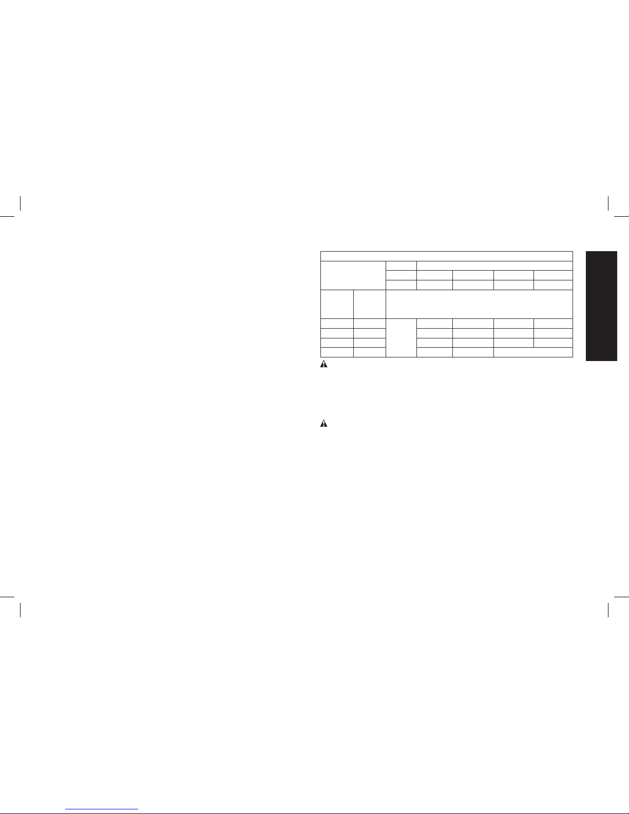
• An extension cord must have adequate wire size (AWG
or American Wire Gauge) for safety. The smaller the gauge
number of the wire, the greater the capacity of the cable, that is
16 gauge has more capacity than 18 gauge. An undersized cord
will cause a drop in line voltage resulting in loss of power and
overheating. When using more than one extension to make up the
total length, be sure each individual extension contains at least the
minimum wire size. The following table shows the correct size to
use depending on cord length and nameplate ampere rating. If in
doubt, use the next heavier gauge. The smaller the gauge number,
the heavier the cord.
Minimum Gauge for Cord Sets
Ampere Rating
Volts Total Length of Cord in Feet (meters)
120V 25 (7.6) 50 (15.2) 100 (30.5) 150 (45.7)
240V 50 (15.2) 100 (30.5) 200 (61.0) 300 (91.4)
More
Than
Not
More
Than
AWG
0 6 18 16 16 14
6 10 18 16 14 12
10 12 16 16 14 12
12 16 14 12 Not Recommended
WARNING: ALWAYS use safety glasses. Everyday eyeglasses are
NOT safety glasses. Also use face or dust mask if cutting operation is
dusty. ALWAYS WEAR CERTIFIED SAFETY EQUIPMENT:
• ANSI Z87.1 eye protection (CAN/CSA Z94.3),
• ANSI S12.6 (S3.19) hearing protection,
• NIOSH/OSHA/MSHA respiratory protection.
WARNING: Some dust created by power sanding, sawing,
grinding, drilling, and other construction activities contains chemicals
known to the State of California to cause cancer, birth defects or other
reproductive harm. Some examples of these chemicals are:
• lead from lead-based paints,
• crystalline silica from bricks and cement and other masonry
products, and
• arsenic and chromium from chemically-treated lumber.
Your risk from these exposures varies, depending on how often you do
this type of work. To reduce your exposure to these chemicals: work
in a well ventilated area, and work with approved safety equipment,
such as those dust masks that are specially designed to filter out
microscopic particles.
• Avoid prolonged contact with dust from power sanding,
sawing, grinding, drilling, and other construction activities.
Page 8
6
English
Wear protective clothing and wash exposed areas with soap
and water. Allowing dust to get into your mouth, eyes, or lay on
the skin may promote absorption of harmful chemicals.
WARNING: Use of this tool can generate and/or disperse dust,
which may cause serious and permanent respiratory or other injury.
Always use NIOSH/OSHA approved respiratory protection appropriate
for the dust exposure. Direct particles away from face and body.
WARNING: Always wear proper personal hearing protection
that conforms to ANSI S12.6 (S3.19) during use. Under some
conditions and duration of use, noise from this product may contribute
to hearing loss.
• The label on your tool may include the following symbols. The
symbols and their definitions are as follows:
V .....................volts A ....................... amperes
Hz...................hertz W ...................... watts
min .................minutes or AC ........... alternating
or DC ....direct current current
...................Class I Construction or AC/DC ...alternating
(grounded) ..........................or direct
..................Class II Construction current
(double insulated)
n
o .....................no load
…/min ............per minute speed
BPM ...............beats per minute n........................rated
IPM ................impacts per minute ..........................speed
RPM ...............revolutions per ...................... earthing
minute terminal
sfpm ...............surface feet ...................... safety alert
.......................per minute symbol
SPM ...............strokes per minute ..................... visible radiation
SAVE THESE INSTRUCTIONS FOR
FUTURE USE
Motor
Be sure your power supply agrees with the nameplate marking.
Voltage decrease of more than 10% will cause loss of power and
overheating. DeWALT tools are factory tested; if this tool does not
operate, check power supply.
E
D
B
A
J
I
FIG. 1
H
G
F
C
L
K
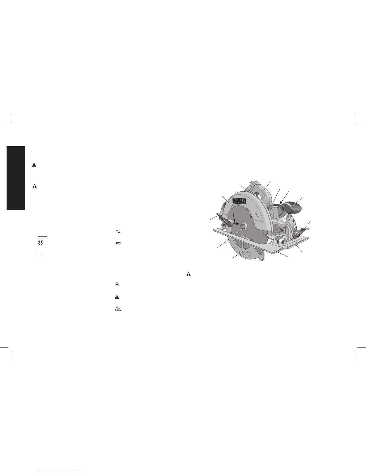
COMPONENTS (Fig. 1)
WARNING: Never modify the power tool or any part of it. Damage
or personal injury could result.
A. Trigger switch H. Foot plate
B. Main handle I. Lower blade guard
C. Blade lock J. Blade clamping screw
D. End cap K. Lower guard lever
E. Auxiliary handle L. Upper blade guard
F. Bevel adjustment lever
G. Bevel angle adjustment mechanism
Page 9
7
English
INTENDED USE
These heavy-duty circular saws are designed for professional wood
cutting applications. DO NOT use water feed attachments with this
saw. DO NOT use abrasive wheels or blades. DO NOT use under wet
conditions or in presence of flammable liquids or gases.
These heavy-duty saws are professional power tools. DO NOT let
children come into contact with the tool. Supervision is required when
inexperienced operators use this tool.
ADJUSTMENTS
Changing Blades
WARNING: To reduce the risk of injury, turn unit off and
disconnect it from power source before installing and removing
accessories, before adjusting or when making repairs. An
accidental start-up can cause injury.
M
J
N
FIG. 2
FIG. 3
K
I
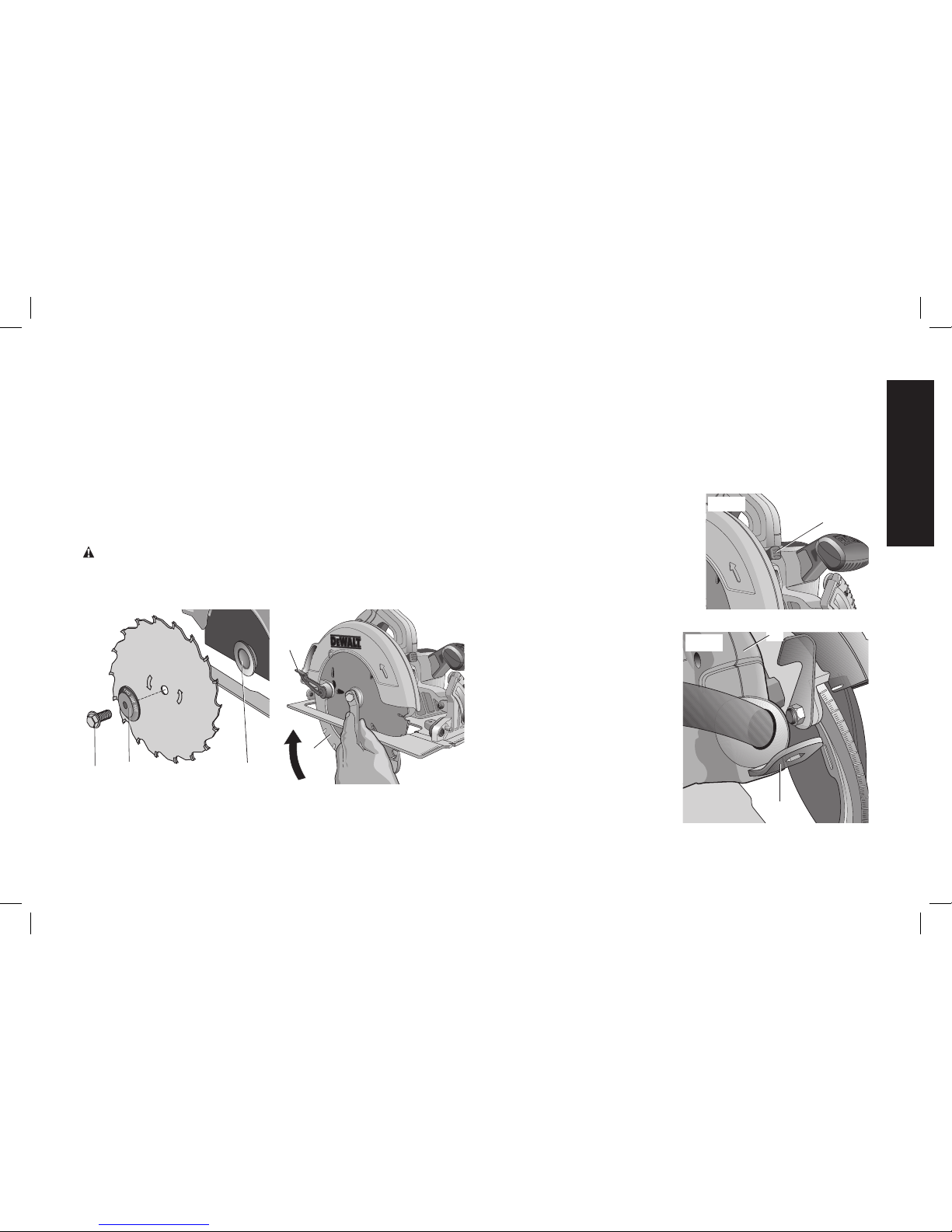
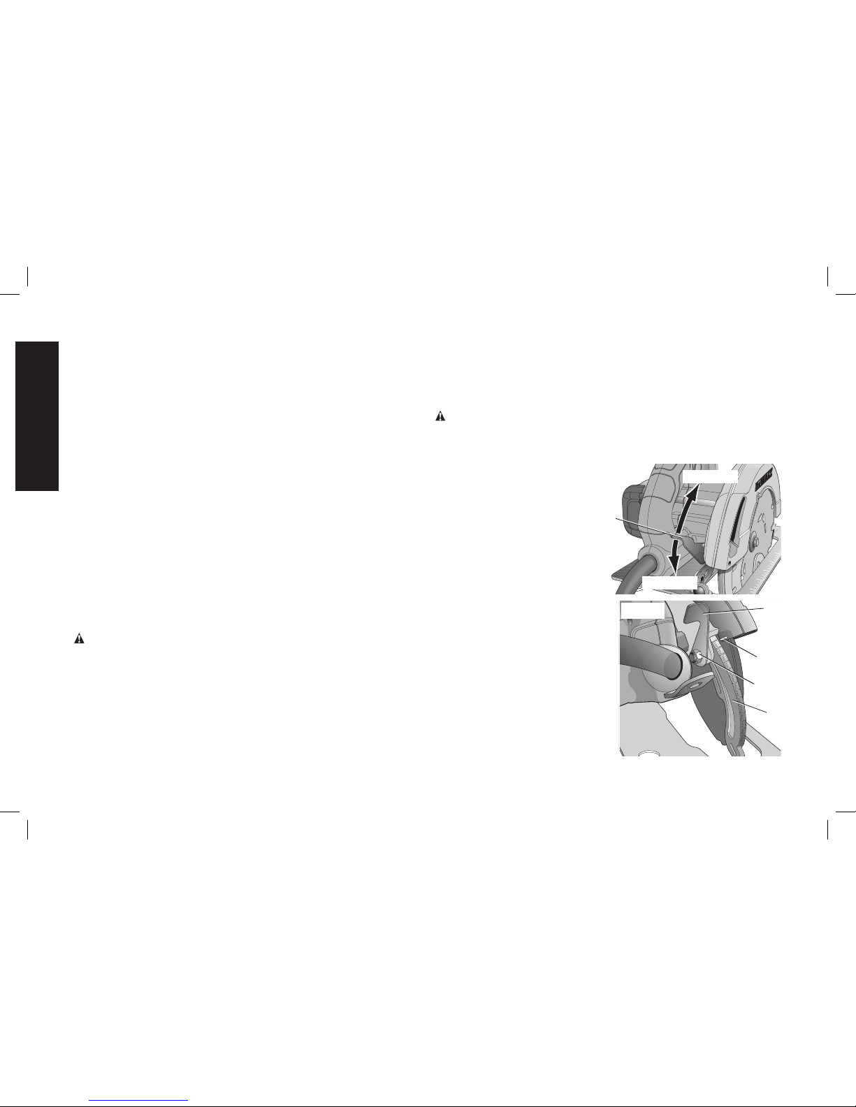
TO INSTALL THE BLADE (FIG. 2–5)
1. Using the lower guard lever (K), retract the lower blade guard (I) and
place blade on saw spindle against the inner clamp washer (M),
making sure that the blade will rotate in the proper direction (the
direction of the rotation arrow on the saw blade and the teeth must
point in the same direction as the direction of rotation arrow on the
saw). Do not assume that the printing on the blade will always be
facing you when properly installed. When retracting the lower blade
guard to install the blade, check the condition and operation of the
lower blade guard to assure that it is working properly. Make sure
it moves freely and does not touch the blade or any other part, in
all angles and depths of cut.
2. Place outer clamp washer (N) on
C
FIG. 4
saw spindle with the large flat
surface against the blade and the
wording on the outer clamp
washer facing you.
3. Thread blade clamping screw (J)
into saw spindle by hand (screw
has right-hand threads and must
be turned clockwise to tighten).
4. Depress the blade lock (C)
FIG. 5
O
FIG. 5
B
while turning the saw spindle
with the blade wrench (O)
stored underneath the main
handle (B) (Fig. 5), until the
blade lock engages and the
blade stops rotating.
5. Tighten the blade clamping
screw firmly with the blade
wrench.
NOTE: Never engage the blade
lock while saw is running, or
engage in an effort to stop the
tool. Never turn the saw on while
the blade lock is engaged. Serious
damage to your saw will result.
Page 10
8
English
TO REPLACE THE BLADE (FIG. 2, 4, 5)
1. To loosen the blade clamping screw (J), depress the blade lock
(C) and turn the saw spindle with the blade wrench (O), stored
underneath the main handle (B), until the blade lock engages
and the blade stops rotating. With the blade lock engaged,
turn the blade clamping screw counterclockwise with the blade
wrench (screw has right-hand threads and must be turned
counterclockwise to loosen).
2. Remove the blade clamping screw (J) and outer clamp washer (N).
Remove old blade.
3. Clean any sawdust that may have accumulated in the guard or
clamp washer area and check the condition and operation of the
lower blade guard as previously outlined. Do not lubricate this area.
4. Select the proper blade for the application (refer to Recommended
Blade Types under Blades). Always use blades that are the
correct size (7-1/4" [178mm] diameter) with the proper size and
shape center hole for mounting on the saw spindle. Always assure
that the maximum recommended speed (rpm) on the saw blade
meets or exceeds the speed (rpm) of the saw.
5. Follow steps 1 through 5 under To Install the Blade, making sure
that the blade will rotate in the proper direction.
LOWER BLADE GUARD
WARNING: The lower blade guard is a safety feature which
reduces the risk of serious personal injury. Never use the saw if
the lower guard is missing, damaged, misassembled or not
working properly. Do not rely on the lower blade guard to
protect you under all circumstances. Your safety depends on
following all warnings and precautions as well as proper
operation of the saw. Check lower guard for proper closing
before each use as outlined in Additional Safety Rules for
Circular Saws. If the lower blade guard is missing or not
working properly, have the saw serviced before using. To
assure product safety and reliability, repair, maintenance and
adjustment should be performed by an authorized service
center or other qualified service organization, always using
identical replacement parts.
Cutting Depth Adjustment (Fig. 6–8)
WARNING: To reduce the risk of injury, turn unit off and
disconnect it from power source before installing and removing
accessories, before adjusting or when making repairs. An
accidental start-up can cause injury.
Your saw is equipped with a
LOOSEN
TIGHTEN
P
FIG. 6
carbide tipped saw blade for
long life and efficient cutting.
Setting the saw at the proper
cutting depth keeps blade
friction to a minimum, removes
sawdust from between the
blade teeth, results in cooler,
faster sawing and reduces the
chance of kickback.
1. Hold the saw firmly. Raise the
FIG. 7
R
Q
P
S
depth adjustment lever (P) to
loosen and move foot plate to
obtain the desired depth of
cut, as shown. Make sure the
depth adjustment lever has
been retightened (lowered)
before operating the saw.
2. Align the appropriate mark on
the depth adjustment strap (R)
with notch (Q) on the upper
blade guard. Your depth is set.
Page 11
9
English
FIG. 8
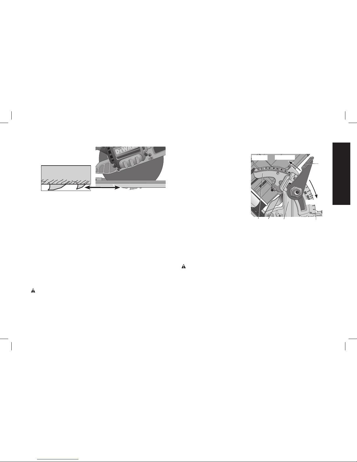
3. For the most efficient cutting action using a carbide tipped saw
blade, set the depth adjustment so that about one half of a tooth
projects below the surface of the wood to be cut.
4. A method of checking for the correct cutting depth is shown in
Figure 8. Lay a piece of the material you plan to cut along the side
of the blade, as shown in the figure, and observe how much tooth
projects beyond the material.
ADJUSTING DEPTH ADJUSTMENT LEVER (FIG. 7)
It may be desirable to adjust the depth adjustment lever (P). It may
loosen in time and hit the foot plate before tighten ing.
To tighten the lever, follow the steps below.
1. Hold depth adjustment lever (P) and loosen the locknut (S).
2. Adjust the depth adjustment lever by rotating it in the desired
direction about 1/8 of a revolution.
3. Retighten nut.
Bevel Angle Adjustment (Fig. 9)
WARNING: To reduce the risk of injury, turn unit off and
disconnect it from power source before installing and removing
accessories, before adjusting or when making repairs. An
accidental start-up can cause injury.
On the front of the saw is a bevel angle adjustment mechanism (G)
which consists of an angle quadrant with a pointer (T) and a bevel
adjustment lever (F). The angle
F
G
TIGHTEN
LOOSEN
T
U
V
FIG. 9
quadrant allows for coarse
adjustment. To achieve better
accuracy in cutting, use the fine
adjustment markings located
on the pivot bracket (U). The full
range of bevel adjustment for
the DWE574 is 0 to 50 degrees
and for the DWE575 and
DWE575SB it is 0 to 57
degrees. The pivot bracket is
graduated in increments of
1degree.
1. To set the saw for a bevel
cut, raise the bevel adjustment lever (F) to loosen the bevel
adjustment.
2. Tilt the foot plate to the desired angle by aligning the pointer (T)
with the desired angle mark on the pivot bracket (U).
3. Retighten the bevel adjustment by lowering the lever.
Bevel Detent (Fig.9)
WARNING: To reduce the risk of injury, turn unit off and
disconnect it from power source before installing and removing
accessories, before adjusting or when making repairs. An
accidental start-up can cause injury.
These circular saws are equipped with a bevel detent feature. As you
tilt the foot plate you will hear a click and feel the foot plate stop at both
22.5 and 45 degrees. If either of these is the desired angle, retighten
the lever (F) by lowering it. If you desire another angle, continue tilting
the foot plate until the coarse bevel pointer (V) or the fine pointer (T)
aligns with the desired mark.
Page 12
10
English
Kerf Indicator (Fig. 10)
The front of the saw foot plate has a kerf indicator for vertical and bevel
cutting. This indicator enables you to guide the saw along cutting lines
penciled on the material being cut. The indicator lines up with the left
(inner) side of the saw blade which makes the slot or “kerf” cut by the
moving blade, fall to the right of the indicator. The markings on the
front of the foot plate are in increments of 1/8"(3.2mm).
FIG. 10
45˚
0˚
Cut Length Indicator (Fig. 11)
The markings on the side of the foot plate
FIG. 11
show the length of the slot being cut into
the material at the full depth of the cut. The
markings are in increments of 1/8" (3.2mm).
OPERATION
WARNING: To reduce the risk of
injury, turn unit off and disconnect it
from power source before installing
and removing accessories, before
adjusting or when making repairs. An
accidental start-up can cause injury.
Proper Hand Position (Fig.12)
WARNING: To reduce the risk of
FIG. 12
B
E
serious personal injury, ALWAYS use
proper hand position as shown.
WARNING: To reduce the risk of
serious personal injury, ALWAYS hold
securely in anticipation of a sudden
reaction.
Proper hand position requires one
hand on the main handle (B), with
the other hand on the auxiliary
handle (E).
Switch (Fig. 1)
Pull the trigger switch (A) to turn the motor on. Releasing the trigger
turns the motor off. This tool has no provision to lock the switch in the
on position, and the tool should never be locked on in any way.
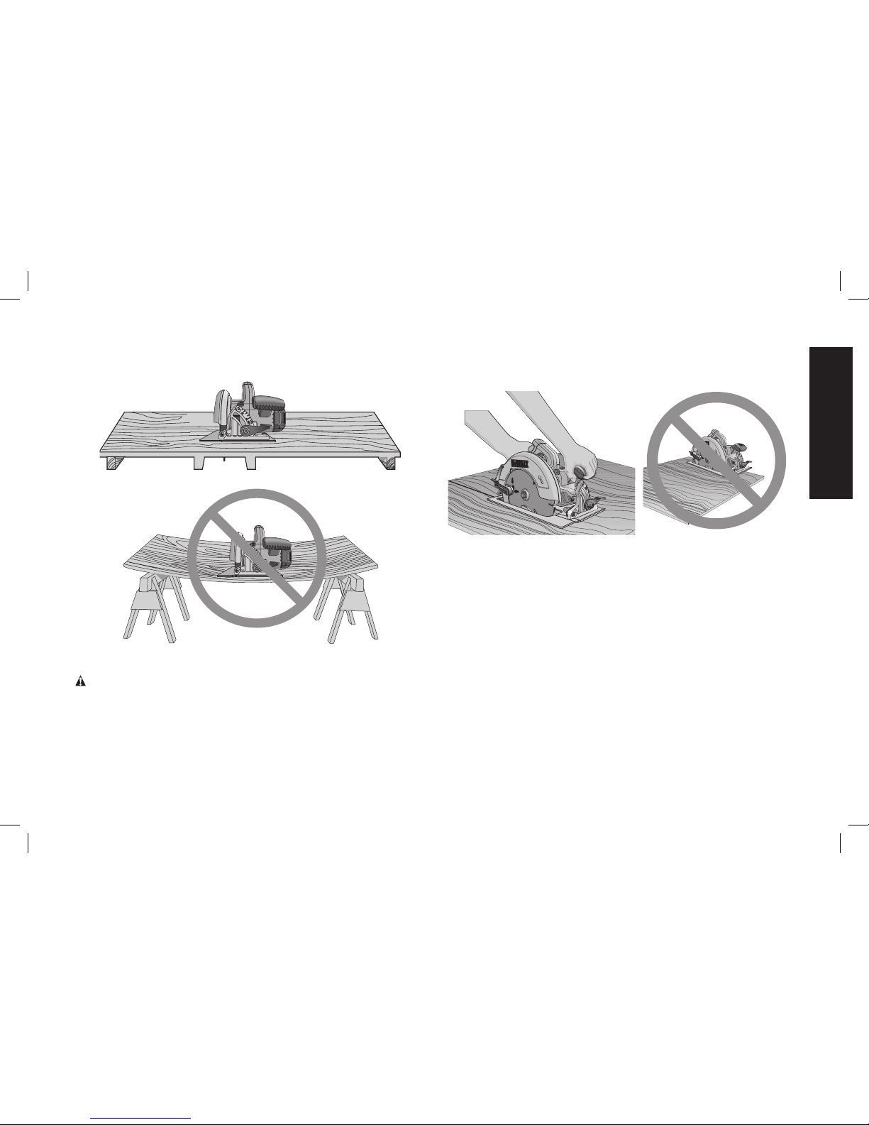
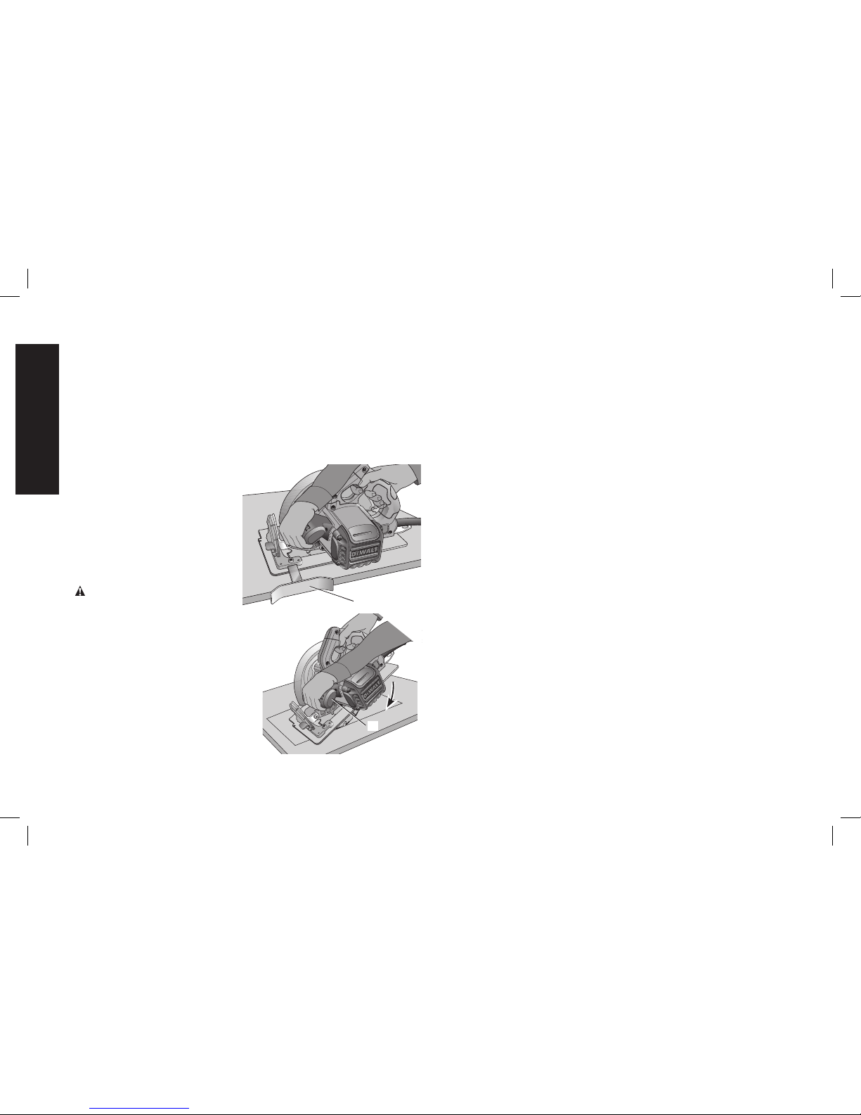
Workpiece Support (Fig. 13–16)
WARNING: To reduce the risk of serious personal injury, support
the work properly and hold the saw firmly to prevent loss of control.
Figures 13 and 15 show proper sawing position. Figures 14 and 16
show an unsafe condition. Hands should be kept away from cutting
area, and power cord is positioned clear of the cutting area so that it
will not get caught or hung up on the work.
To avoid kickback, ALWAYS support board or panel NEAR the cut,
(Fig. 13 and 15). DON’T support board or panel away from the cut
(Fig.14 and 16). When operating the saw, keep the cord away from
the cutting area and prevent it from becoming hung up on the work
piece.
ALWAYS DISCONNECT SAW BEFORE MAKING ANY ADJUST MENTS!
Place the work with its “good” side—the one on which appearance is
Page 13
11
English
most important—down. The saw cuts upward, so any splintering will be
on the work face that is up when you saw it.
FIG. 13
FIG. 14
Cutting
WARNING: Never attempt to use this tool by resting it upside
down on a work surface and bringing the material to the tool. Always
securely clamp the workpiece and bring the tool to the workpiece,
securely holding the tool with two hands as shown in Figure 15.
Place the wider portion of the saw foot plate on that part of the work
piece which is solidly supported, not on the section that will fall off when
the cut is made. As examples, Figure15 illustrates the RIGHT way to
cut off the end of a board. Always clamp work. Don’t try to hold short
pieces by hand! Remember to support cantilevered and overhanging
material. Use caution when sawing material from below.
FIG. 15 FIG. 16
Be sure saw is up to full speed before blade contacts material to be cut.
Starting saw with blade against material to be cut or pushed forward
into kerf can result in kickback. Push the saw forward at a speed which
allows the blade to cut without laboring. Hardness and toughness can
vary even in the same piece of material, and knotty or damp sections
can put a heavy load on the saw. When this happens, push the saw
more slowly, but hard enough to keep working without much decrease
in speed. Forcing the saw can cause rough cuts, inaccuracy, kickback,
and over-heating of the motor. Should your cut begin to go off the line,
don’t try to force it back on. Release the switch and allow blade to come
to a complete stop. Then you can withdraw the saw, sight anew, and
start a new cut slightly inside the wrong one. In any event, withdraw the
saw if you must shift the cut. Forcing a correction inside the cut can stall
the saw and lead to kickback.
IF SAW STALLS, RELEASE THE TRIGGER AND BACK THE SAW
UNTIL IT IS LOOSE. BE SURE BLADE IS STRAIGHT IN THE CUT
AND CLEAR OF THE CUTTING EDGE BEFORE RESTARTING.
Page 14
12
English
As you finish a cut, release the trigger and allow the blade to stop
before lifting the saw from the work. As you lift the saw, the springtensioned telescoping guard will automatically close under the blade.
Remember the blade is exposed until this occurs. Never reach under
the work for any reason. When you have to retract the telescoping
guard manually (as is necessary for starting pocket cuts) always use
the retracting lever.
NOTE: When cutting thin strips, be careful to ensure that small cutoff
pieces don’t hang up on inside of lower guard.
RIPPING (FIG. 17)
FIG. 17
W
Ripping is the process of cutting
wider boards into narrower
strips – cutting grain lengthwise.
Hand guiding is more difficult for
this type of sawing and the use
of DeWALT DW3278 rip guide
(W) is recommended.
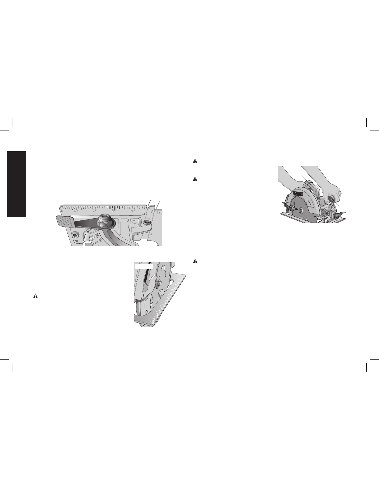
POCKET CUTTING (FIG. 18)
WARNING: Never tie the
blade guard in a raised position.
Never move the saw backwards
FIG. 18
E
when pocket cutting. This may
cause the unit to raise up off the
work surface which could cause
injury.
A pocket cut is one that is made in
a floor, wall or other flat surface.
1. Adjust the saw foot plate so the
blade cuts at desired depth.
2. Tilt the saw forward and rest
front of the foot plate on
material to be cut.
3. Using the lower guard lever, retract lower blade guard to an
upward position. Lower rear of foot plate until blade teeth almost
touch cutting line.
4. Release the blade guard (its contact with the work will keep it
in position to open freely as you start the cut). Remove hand
from guard lever and firmly grip auxiliary handle (E), as shown in
Figure 18. Position your body and arm to allow you to resist
kickback if it occurs.
5. Make sure blade is not in contact with cutting surface before
starting saw.
6. Start the motor and gradually lower the saw until its foot plate rests
flat on the material to be cut. Advance saw along the cutting line
until cut is completed.
7. Release trigger and allow blade to stop completely before
withdrawing the blade from the material.
8. When starting each new cut, repeat as above.
Kickback
When the saw blade becomes pinched or twisted in the cut, kickback
can occur. The saw is thrust rapidly back toward the operator. When
the blade is pinched or bound tightly by the kerf closing down, the
blade stalls and the motor reaction drives the unit backward. When the
blade becomes twisted or misaligned in the cut, the teeth at the back
edge of the blade can dig into the top surface of the wood causing
the blade to climb out of the kerf and jump back toward the operator.
Kickback is more likely to occur when any of the following conditions
exist.
1. IMPROPER WORKPIECE SUPPORT
A. Sagging or improper lifting of the cut off piece can cause
pinching of the blade and lead to kickback (Fig. 14).
Page 15

13
English
B. Cutting through material supported at the outer ends only can
cause kickback. As the material weakens it sags, closing down
the kerf and pinching the blade.
C. Cutting off a cantilevered or overhanging piece of material from
the bottom up in a vertical direction can cause kickback. The
falling cut off piece can pinch the blade.
D. Cutting off long narrow strips (as in ripping) can cause kickback.
The cut off strip can sag or twist closing the kerf and pinching
the blade.
E. Snagging the lower guard on a surface below the material
being cut momentarily reduces operator control. The saw can
lift partially out of the cut increasing the chance of blade twist.
2. IMPROPER DEPTH OF CUT SETTING ON SAW
To make the most efficient cut, the blade should protrude only far
enough to expose 1/2 of a tooth as shown in Figure 9. This allows
the foot plate to support the blade and minimizes twisting and
pinching in the material. Refer to Cutting Depth Adjustment.
3. BLADE TWISTING (MISALIGNMENT IN CUT)
A. Pushing harder to cut through a knot, a nail, or a hard grain
area can cause the blade to twist.
B. Trying to turn the saw in the cut (trying to get back on the
marked line) can cause blade twist.
C. Over-reaching or operating the saw with poor body control (out
of balance), can result in twisting the blade.
D. Changing hand grip or body position while cutting can result in
blade twist.
E. Backing up the saw to clear blade can lead to twist if it is not
done carefully.
4. MATERIALS THAT REQUIRE EXTRA ATTENTION
A. Wet lumber
B. Green lumber (material freshly cut or not kiln dried)
C. Pressure treated lumber (material treated with preservatives or
anti-rot chemicals)
5. USE OF DULL OR DIRTY BLADES
Dull blades cause increased loading of the saw. To compensate,
an operator will usually push harder which further loads the unit
and promotes twisting of the blade in the kerf. Worn blades may
also have insufficient body clearance which increases the chance
of binding and increased loading.
6. LIFTING THE SAW WHEN MAKING BEVEL CUTS
Bevel cuts require special operator attention to proper cutting
techniques – especially guidance of the saw. Both blade angle to
the foot plate and greater blade surface in the material increase the
chance for binding and misalignment (twist) to occur.
7. RESTARTING A CUT WITH THE BLADE TEETH JAMMED
AGAINST THE MATERIAL
The saw should be brought up to full operating speed before
starting a cut or restarting a cut after the unit has been stopped
with the blade in the kerf. Failure to do so can cause stalling and
kickback.
Any other conditions which could result in pinching, binding, twisting,
or misalignment of the blade could cause kickback. Refer to
Additional Safety Instructions and Operation for procedures and
techniques that will minimize the occurrence of kickback.
MAINTENANCE
WARNING: To reduce the risk of injury, turn unit off and
disconnect it from power source before installing and removing
accessories, before adjusting or when making repairs. An
accidental start-up can cause injury.
Page 16

14
English
Cleaning
WARNING: Blow dirt and dust out of all air vents with clean, dry air
at least once a week. To minimize the risk of eye injury, always wear
ANSI Z87.1 approved eye protection when performing this.
WARNING: Never use solvents or other harsh chemicals for cleaning
the non-metallic parts of the tool. These chemicals may weaken the
plastic materials used in these parts. Use a cloth dampened only with
water and mild soap. Never let any liquid get inside the tool; never
immerse any part of the tool into a liquid.
Lubrication
Self lubricating ball and roller bearings are used in the tool and
relubrication is not required. However, it is recommended that, once
a year, you take or send the tool to a service center for a thorough
cleaning, inspection and lubrication of the gear case.
Electric Brake (DWE575SB)
Your saw has an automatic electric brake which is designed to stop
the blade from coasting in about two seconds, after you release the
trigger switch. It is useful when making certain cuts in wood where a
coasting blade would result in a wide, imprecise cut.
Occasionally, the brake will not function properly and won’t stop the
saw in the 2 seconds discussed above. If this condition persists, turn
the saw on and off four or five times. If the brake still does not stop
the blade in about 2 seconds, the problem may be worn brushes.
Have the brushes replaced at a DeWALT authorized service center.
Repairs
WARNING: To assure product SAFETY and RELIABILITY, repairs,
maintenance and adjustment (including brush inspection and
replacement) should be performed by a DeWALT factory service
center or a DeWALT authorized service center. Always use identical
replacement parts..
Refer to Brushes for brush replacement information.
Brushes (Fig. 19)
WARNING: To reduce the risk of injury, turn unit off and
disconnect it from power source before installing and removing
accessories, before adjusting or when making repairs. An
accidental start-up can cause injury.
Inspect carbon brushes
D
X
X
FIG. 19
regularly by disconnecting the
tool from the power source,
removing the four end cap
screws (X) with a screwdriver,
then removing the end
cap (D).
Keep brushes clean and
sliding freely in their guides.
Always replace a used brush
in the same orientation in
the holder as it was prior to
removal. Carbon brushes have varying symbols stamped into their
sides, and if either brush is worn down to the line closest to the
spring, take the tool to a DeWALT authorized service center for brush
assembly replacement. Use only identical DeWALT brushes. Always
replace the end cap after inspecting or servicing brushes. The tool
should be allowed to “run in” (run at no load without a blade) for 5
minutes before use to seat new brushes.
While “running in” DO NOT TIE, TAPE, OR OTHERWISE LOCK THE
TRIGGER SWITCH ON. HOLD BY HAND ONLY.
Foot Plate Adjustment
WARNING: To reduce the risk of injury, turn unit off and
disconnect it from power source before installing and removing
accessories, before adjusting or when making repairs. An
accidental start-up can cause injury.
Page 17

15
English
Your foot plate has been factory set to assure that the blade is
perpendicular to the foot plate. If after extended use you need to
re-align the blade, follow the directions below:
ADJUSTING FOR 90 DEGREE CUTS (FIG. 1, 20)
1. Return the saw to
FIG. 20
Y
0degrees bevel.
2. Place the saw on its
side, and retract the
lower guard.
3. Set the depth of cut
at approximately 2"
(51mm).
4. Loosen the bevel
adjustment lever (F).
Place a square against
the blade and the
foot plate as shown in
Figure20.
5. Using a hex wrench, turn the set screw (Y) on the underside of the
foot plate until the blade and the foot plate are both in flush contact
with the square. Retighten the bevel adjustment lever.
ADJUSTING BEVEL ADJUSTMENT LEVER
It may be desirable to adjust the
FIG. 21
Z
F
bevel adjustment lever. It may
loosen in time and hit the foot plate
before tighten ing.
To tighten the lever, follow the
steps below.
1. Hold bevel adjustment lever (F)
and loosen the locknut (Z).
2. Adjust the bevel adjustment lever by rotating it in the desired
direction about 1/8 of a revolution.
3. Retighten nut.
Blades
A dull blade will cause inefficient cutting, overload on the saw motor,
excessive splintering and increase the possibility of kickback. Change
blades when it is no longer easy to push the saw through the cut,
when the motor is straining, or when excessive heat is built up in the
blade. It is a good practice to keep extra blades on hand so that sharp
blades are available for immediate use. Dull blades can be sharpened
in most areas; see SAWS-SHARPENING in the yellow pages.
Hardened gum on the blade can be removed with kerosene,
turpentine, or oven cleaner. Anti-stick coated blades can be used
in applications where excessive build-up is encountered, such as
pressure treated and green lumber.
RECOMMENDED BLADE TYPES
COMBINATION FRAMING 5/8" Round arbor, 24 teeth
All purpose fast rip and cross cuts.
PRESSURE TREATED/ 5/8" Round arbor, 20 teeth
WET LUMBER Coated - Resistant to gum build-up
EXTREME DURABILITY 5/8" Round arbor, 18 teeth
Coated, rock carbide
FINISHING 5/8" Round arbor, 36 teeth
More teeth for finer finish cuts.
FAST CUT FRAMING 5/8" Round arbor, 18 teeth
Fastest blade for rips and cross cuts
Page 18

16
English
Accessories
WARNING: Since accessories, other than those offered by DeWALT,
have not been tested with this product, use of such accessories with
this tool could be hazardous. To reduce the risk of injury, only DeWALT,
recommended accessories should be used with this product.
Recommended accessories for use with your tool are available at
extra cost from your local dealer or authorized service center. If you
need assistance in locating any accessory, please contact DeWALT
Industrial Tool Co., 701 East Joppa Road, Towson, MD 21286, call
1-800-4-DeWALT (1-800-433-9258) or visit our website www.dewalt.
com.
DO NOT USE WATER FEED ATTACHMENTS WITH THIS SAW.
VISUALLY EXAMINE CARBIDE BLADES BEFORE USE. REPLACE IF
DAMAGED.
Three Year Limited Warranty
DeWA LT will repair, without charge, any defects due to faulty materials
or workmanship for three years from the date of purchase. This
warranty does not cover part failure due to normal wear or tool abuse.
For further detail of warranty coverage and warranty repair information,
visit www.dewalt.com or call 1-800-4-DeWALT (1-800-433-9258).
This warranty does not apply to accessories or damage caused where
repairs have been made or attempted by others. This warranty gives
you specific legal rights and you may have other rights which vary in
certain states or provinces.
In addition to the warranty, DeWALT tools are covered by our:
1 YEAR FREE SERVICE
DeWA LT will maintain the tool and replace worn parts caused by
normal use, for free, any time during the first year after purchase.
90 DAY MONEY BACK GUARANTEE
If you are not completely satisfied with the performance of your
DeWA LT Power Tool, Laser, or Nailer for any reason, you can return it
within 90 days from the date of purchase with a receipt for a full refund
– no questions asked.
LATIN AMERICA: This warranty does not apply to products sold in
Latin America. For products sold in Latin America, see country specific
warranty information contained either in the packaging, call the local
company or see website for warranty information.
FREE WARNING LABEL REPLACEMENT: If your warning labels
become illegible or are missing, call 1-800-4-DeWALT (1-800-433-
9258) for a free replacement.
Page 19

Français
17
Définitions: lignes directrices en
matière de sécurité
Les définitions ci-dessous décrivent le niveau de danger pour
chaque mot-indicateur employé. Lire le mode d’emploi et
porter une attention particulière à ces symboles.
DANGER: indique une situation dangereuse imminente
qui, si elle n’est pas évitée, entraînera la mort ou des
blessures graves.
AVERTISSEMENT: indique une situation potentiellement
dangereuse qui, si elle n’est pas évitée, pourrait entraîner la
mort ou des blessures graves.
ATTENTION: indique une situation potentiellement
dangereuse qui, si elle n’est pas évitée, pourrait entraîner
des blessures légères ou modérées.
AVIS : indique une pratique ne posant aucun risque de
dommages corporels mais qui par contre, si rien n’est fait
pour l’éviter, pourrait poser des risques de dommages
matériels.
IPOUR TOUTE QUESTION OU REMARQUE AU SUJET DE CET
OUTIL OU DE TOUT AUTRE OUTIL DeWALT, COMPOSEZ LE
NUMÉRO SANS FRAIS : 1-800-4-DeWALT (1-800-433-9258).
AVERTISSEMENT : afin de réduire le risque de blessures, lire
le mode d’emploi de l’outil.
Avertissements de sécurité généraux
pour les outils électriques
AVERTISSEMENT ! Lire tous les avertissements de
sécurité et toutes les directives. Le non-respect des
avertissements et des directives pourrait se solder par un choc
électrique, un incendie et/ou une blessure grave.
CONSERVER TOUS LES AVERTISSEMENTS
ET TOUTES LES DIRECTIVES POUR UN
USAGE ULTÉRIEUR
Le terme « outil électrique » cité dans les avertissements se rapporte
à votre outil électrique à alimentation sur secteur (avec fil) ou par piles
(sans fil).
1) SÉCURITÉ DU LIEU DE TRAVAIL
a) Tenir l’aire de travail propre et bien éclairée. Les lieux
encombrés ou sombres sont propices aux accidents.
b) Ne pas faire fonctionner d’outils électriques dans un
milieu déflagrant, tel qu’en présence de liquides, de
gaz ou de poussières inflammables. Les outils électriques
produisent des étincelles qui pourraient enflammer la poussière
ou les vapeurs.
c) Éloigner les enfants et les personnes à proximité pendant
l’utilisation d’un outil électrique. Une distraction pourrait en
faire perdre la maîtrise à l’utilisateur.
2) SÉCURITÉ EN MATIÈRE D’ÉLECTRICITÉ
a) Les fiches des outils électriques doivent correspondre
à la prise. Ne jamais modifier la fiche d’aucune façon.
Ne jamais utiliser de fiche d’adaptation avec un outil
électrique mis à la terre. Le risque de choc électrique sera
réduit par l’utilisation de fiches non modifiées correspondant à
la prise.
Page 20

Français
18
b) Éviter tout contact physique avec des surfaces mises à la
terre comme des tuyaux, des radiateurs, des cuisinières
et des réfrigérateurs. Le risque de choc électrique est plus
élevé si votre corps est mis à la terre.
c) Ne pas exposer les outils électriques à la pluie ou à
l’humidité. La pénétration de l’eau dans un outil électrique
augmente le risque de choc électrique.
d) Ne pas utiliser le cordon de façon abusive. Ne jamais
utiliser le cordon pour transporter, tirer ou débrancher un
outil électrique. Tenir le cordon éloigné de la chaleur, de
l’huile, des bords tranchants et des pièces mobiles. Les
cordons endommagés ou enchevêtrés augmentent les risques
de choc électrique.
e) Pour l’utilisation d’un outil électrique à l’extérieur, se
servir d’une rallonge convenant à cette application.
L’utilisation d’une rallonge conçue pour l’extérieur réduira les
risques de choc électrique.
f) S’il est impossible d’éviter l’utilisation d’un outil électrique
dans un endroit humide, brancher l’outil dans une prise
ou sur un circuit d’alimentation dotés d’un disjoncteur de
fuite à la terre (GFCI). L’utilisation de ce type de disjoncteur
réduit les risques de choc électrique.
3) SÉCURITÉ PERSONNELLE
a) Être vigilant, surveiller le travail effectué et faire preuve
de jugement lorsqu’un outil électrique est utilisé. Ne
pas utiliser d’outil électrique en cas de fatigue ou sous
l’influence de drogues, d’alcool ou de médicaments. Un
simple moment d’inattention en utilisant un outil électrique peut
entraîner des blessures corporelles graves.
b) Utiliser des équipements de protection individuelle.
Toujours porter une protection oculaire. L’utilisation
d’équipements de protection comme un masque antipoussière,
des chaussures antidérapantes, un casque de sécurité ou des
protecteurs auditifs lorsque la situation le requiert réduira les
risques de blessures corporelles.
c) Empêcher les démarrages intempestifs. S’assurer que
l’interrupteur se trouve à la position d’arrêt avant de
relier l’outil à une source d’alimentation et/ou d’insérer
un bloc-piles, de ramasser ou de transporter l’outil.
Transporter un outil électrique alors que le doigt repose sur
l’interrupteur ou brancher un outil électrique dont l’interrupteur
est à la position de marche risque de provoquer un accident.
d) Retirer toute clé de réglage ou clé avant de démarrer
l’outil. Une clé ou une clé de réglage attachée à une partie
pivotante de l’outil électrique peut provoquer des blessures
corporelles.
e) Ne pas trop tendre les bras. Conserver son équilibre en
tout temps. Cela permet de mieux maîtriser l’outil électrique
dans les situations imprévues.
f) S’habiller de manière appropriée. Ne pas porter de
vêtements amples ni de bijoux. Garder les cheveux, les
vêtements et les gants à l’écart des pièces mobiles. Les
vêtements amples, les bijoux ou les cheveux longs risquent de
rester coincés dans les pièces mobiles.
g) Si des composants sont fournis pour le raccordement de
dispositifs de dépoussiérage et de ramassage, s’assurer
que ceux-ci sont bien raccordés et utilisés. L’utilisation d’un
dispositif de dépoussiérage peut réduire les dangers engendrés
par les poussières.
4) UTILISATION ET ENTRETIEN D’UN OUTIL ÉLECTRIQUE
a) Ne pas forcer un outil électrique. Utiliser l’outil électrique
approprié à l’application. L’outil électrique approprié
effectuera un meilleur travail, de façon plus sûre et à la vitesse
pour laquelle il a été conçu.
Page 21

Français
19
b) Ne pas utiliser un outil électrique dont l’interrupteur
est défectueux. Tout outil électrique dont l’interrupteur est
défectueux est dangereux et doit être réparé.
c) Débrancher la fiche de la source d’alimentation et/ou du
bloc-piles de l’outil électrique avant de faire tout réglage
ou changement d’accessoire ou avant de ranger l’outil.
Ces mesures préventives réduisent les risques de démarrage
accidentel de l’outil électrique.
d) Ranger les outils électriques hors de la portée des enfants
et ne permettre à aucune personne n’étant pas familière
avec un outil électrique ou son mode d’emploi d’utiliser
cet outil. Les outils électriques deviennent dangereux entre les
mains d’utilisateurs inexpérimentés.
e) Entretien des outils électriques. Vérifier si les pièces
mobiles sont mal alignées ou coincées, si des pièces sont
brisées ou présentent toute autre condition susceptible
de nuire au bon fonctionnement de l’outil électrique.
En cas de dommage, faire réparer l’outil électrique
avant toute nouvelle utilisation. Beaucoup d’accidents sont
causés par des outils électriques mal entretenus.
f) S’assurer que les outils de coupe sont aiguisés et
propres. Les outils de coupe bien entretenus et affûtés sont
moins susceptibles de se coincer et sont plus faciles à maîtriser.
g) Utiliser l’outil électrique, les accessoires, les forets,
etc. conformément aux présentes directives en tenant
compte des conditions de travail et du travail à effectuer.
L’utilisation d’un outil électrique pour toute opération autre que
celle pour laquelle il a été conçu est dangereuse.
5) RÉPARATION
a) Faire réparer l’outil électrique par un réparateur
professionnel en n’utilisant que des pièces de rechange
identiques. Cela permettra de maintenir une utilisation
sécuritaire de l’outil électrique.
Consignes de sécurité propres à toutes
les scies
PROCÉDURES DE COUPE
a) DANGER : éloigner les mains des zones et organes
de coupe. Maintenir la deuxième main sur la poignée
auxiliaire ou le boîtier du moteur. Lorsque les deux mains
maintiennent la scie, la lame ne peut les couper.
b) N’essayez pas de tenir le dessous de l’ouvrage. Le
protège-lame ne peut pas vous protéger de la lame en dessous
de l'ouvrage.
c) Ajustez la profondeur de coupe à l’épaisseur de l’ouvrage.
Moins d’une dent entière de lame devrait être visible en dessous
de l’ouvrage.
d) Ne tenez jamais dans vos mains ou sur vos genoux un
ouvrage qui est en cours de coupe. Fixez votre ouvrage
sur une plateforme stable. Il est important de soutenir
correctement l’ouvrage afin de minimiser l’exposition du corps
à la lame, le risque de coincement de la lame ou la perte de
contrôle de l’outil.
e) Tenez l’outil électrique uniquement par les parties
isolées prévues à cet effet pendant toute utilisation où
l’organe de coupe pourrait entrer en contact avec des
fils électriques ou son propre cordon d’alimentation. Tout
contact avec un fil « sous tension » risque de mettre « sous
tension» les pièces métalliques exposées de l’outil et de causer
une décharge électrique à l’opérateur.
f) Pendant les coupes de refente, utilisez toujours un guide
de refente ou un guide à bord droit. Ceci augmente toujours
l’exactitude de la coupe et diminue la possibilité de coincement
de la lame.
g) Utilisez toujours des lames dont l’alésage central est
de la taille et de la forme appropriées (soit en forme
Page 22

Français
20
b) En cas de coincement de la lame ou d’interruption d'une
coupe pour une raison quelconque, relâchez la gâchette
et tenez la scie immobile dans l’ouvrage jusqu’à ce que la
lame se soit immobilisée complètement. Ne tentez jamais
de retirer la scie de l’ouvrage ou de la tirer vers l’arrière
pendant que la lame est en mouvement, car un rebond
risquerait de se produire. Évaluez la situation et prenez les
mesures correctives nécessaires pour éliminer la cause du
coincement de la lame.
c) Lorsque vous remettez une scie en marche quand
l’ouvrage est présent, centrez la lame de scie dans le trait
de scie et vérifiez que les dents de la lame ne sont pas
engagées dans le matériau de l’ouvrage. Si la lame de scie
se coince, elle peut grimper hors de l’ouvrage ou rebondir sur
celui-ci quand la scie est remise en marche.
d) Soutenez les panneaux de grande taille de façon à
minimiser le risque de pincement et de rebond de la
lame. Les panneaux de grande taille ont tendance à s’affaisser
sous leur propre poids. Des supports doivent être placés des
deux côtés sous le panneau, à proximité de la ligne de coupe et
à proximité du rebord du panneau.
e) N’utilisez pas de lame émoussée ou endommagée. Des
lames non aiguisées ou mal installées produisent un trait de scie
étroit qui cause une friction excessive, le coincement de la lame
et un effet de rebond.
f) Les leviers de réglage de la profondeur et de l’angle de
coupe de la lame doivent être bien serrés et assujettis
avant de réaliser une coupe. Une modification du réglage de
la lame pendant la coupe risque d’entraîner un coincement et
un rebondissement de la lame.
g) Faites preuve d’une extrême prudence au moment de
scier dans un mur ou à tout autre endroit où la visibilité
est réduite. La lame en saillie est susceptible de couper des
objets pouvant causer des effets de rebonds.
de diamant, soit en forme de rond). Les lames qui ne
correspondent pas aux pièces de montage de la cie tourneront
de façon excentrique, ce qui causera une perte de contrôle de
l’outil.
h) Ne vous servez jamais de rondelles ou de boulons
de lames qui sont endommagés ou inappropriés. Les
rondelles et le boulon de lame ont été conçus spécifiquement
pour votre scie dans le but d'assurer une performance optimale
et un fonctionnement sans danger.
Consignes additionnelles de sécurité
propres à toutes les scies
CAUSES DE REBONDS ET AVERTISSEMENTS AFFÉRENTS:
– Le rebond est une réaction subite (causée par une lame de
scie pincée, coincée ou mal alignée) qui peut entraîner le
soulèvement d’une scie non contrôlée, sa sortie de l’ouvrage et
sa projection en direction de l'utilisateur.
– Si la lame est pincée ou coincée fortement pendant l’abaissement
de la scie, la lame se cale et le moteur réagit en entraînant
rapidement l’outil vers l’arrière dans la direction de l’opérateur.
– Si la lame se tord ou perd son alignement correct au cours
de la coupe, les dents sur le bord arrière de la lame peuvent
entamer la surface supérieure du bois, forçant ainsi la lame à
sortir du trait de scie et à « sauter » vers l’arrière en direction de
l’opérateur.
Le rebond est la conséquence d’une mauvaise utilisation de la scie et/
ou de procédures ou de conditions incorrectes, et il peut être évité en
prenant les précautions qui sont décrites ci-dessous :
a) Maintenez fermement la scie avec vos deux mains et
positionnez vos bras de façon à résister aux forces de
rebond. Les forces de rebond peuvent être contrôlées par
l’utilisateur quand les précautions appropriées sont prises.
Page 23

Français
21
FONCTION DU CARTER INFÉRIEUR
a) Inspectez le protège-lame inférieur avant chaque
utilisation pour vous assurer qu’il se ferme correctement.
Ne faites pas fonctionner la scie si le protège-lame
inférieur ne se déplace pas librement et ne se ferme
pas instantanément. Ne forcez jamais le protège-lame
inférieur dans la position ouverte à l’aide d’un collier de
serrage ou d’une attache. Il est possible que le protège-
lame inférieur se torde en cas de chute accidentelle de la
scie. Soulevez le protège-lame inférieur à l’aide de la poignée
rétractable et assurez-vous qu’il se déplace sans problème et
qu’il ne touche pas la lame ou une autre pièce, quel que soit
l’angle ou la profondeur de la coupe.
b) Vérifiez le fonctionnement du ressort du protège-lame
inférieur. Si le protège-lame inférieur et le ressort ne
fonctionnent pas correctement, ils doivent être réparés
avant l’emploi. Le protège-lame inférieur peut parfois mal
fonctionner à cause de pièces endommagées, d’accumulation
de résine ou de débris.
c) Le protège-lame inférieur doit être rétracté à la main
uniquement à l’occasion de coupes spéciales telles que
les « coupes en plongée » ou les « coupes composées ».
Soulevez le protège-lame inférieur à l’aide la poignée
rétractable et relâchez-le dès que la lame pénètre dans le
matériau de l’ouvrage. Pour toute autre opération de sciage,
le protège-lame inférieur doit fonctionner automatiquement.
d) Vérifiez toujours que le protège-lame inférieur couvre
la lame avant de placez la scie sur un banc ou sur le
sol. Une lame non protégée qui tourne librement entraînera le
mouvement de la scie en marche arrière, ce qui provoquera
la coupe de tout se qui se trouve sur sa trajectoire. Soyez
conscient du temps nécessaire à la lame pour s'arrêter une fois
que la gâchette est relâchée.
Consignes spécifiques additionnelles de
sécurité propres aux scies circulaires
AVERTISSEMENT: ne pas utiliser de meules ou de lames
abrasives.
AVERTISSEMENT : ne pas utiliser des dispositifs
d’alimentation en eau.
• Utilisez des serres de fixation ou un autre dispositif de
fixation permettant de soutenir et de retenir la pièce sur
une plate-forme stable. Tenir la pièce avec la main ou contre son
corps n’est pas suffisamment stable et risque de provoquer une
perte de maîtrise de l’outil.
• Se placer à gauche ou à droite de la lame de scie et non
dans sa trajectoire. L'effet de rebond risque de faire rebondir la
scie vers l’arrière (consulter les rubriques Causes des rebonds
et méthodes de prévention pouvant être utilisées par
l’utilisateur et REBOND).
• Éviter de couper des clous. Inspecter le bois et retirer les
clous présents avant toute coupe.
• La vitesse nominale des accessoires doit être équivalente
ou supérieure à celle recommandée sur l’étiquette
d’avertissement de l’outil. Une meule ou tout autre accessoire
tournant à une vitesse supérieure à sa vitesse nominale peut
se désintégrer et poser des risques de dommages corporels.
L’intensité nominale des accessoires utilisés doit être supérieure à
la vitesse minimum des outils, indiquée sur la plaque signalétique.
• Avant toute utilisation, s’assurer systématiquement que la scie est
propre.
• En cas de bruit inhabituel ou de fonctionnement anormal, arrêter
l’utilisation de la scie et la faire vérifier.
• S’assurer systématiquement que tous les composants sont
installés correctement et solidement avant toute utilisation de l’outil.
Page 24

Français
22
• Prendre systématiquement des précautions lors de l’installation et
du retrait de la lame de la scie.
• Attendre systématiquement que le moteur tourne à plein régime
avant d’entamer une coupe.
• Maintenir les poignées propres et sèches, exemptes d’huile ou
de graisse. Pendant l’utilisation, maintenir fermement l’outil à
deux mains.
• Rester constamment vigilant, particulièrement lors d’opérations
répétitives et monotones. Rester systématiquement conscient de
la position des mains par rapport à la lame.
• Se protéger de la chute de tout rebut pendant la coupe. Ils
pourraient être brûlants, coupants et/ou lourds et poser des
risques de dommages corporels sérieux.
• Remplacer ou faire réparer tout cordon endommagé. S’assurer
que la rallonge est en bon état. N’utiliser que des rallonges trifilaires
munies de fiches tripolaires, et des prises tripolaires acceptant la
fiche de l’outil.
• Prendre des précautions à proximité des évents, car ils
cachent des pièces mobiles. Vêtements amples, bijoux ou
cheveux longs risquent de rester coincés dans ces pièces mobiles.
• Pour la sécurité de l’utilisateur, utiliser une rallonge de
calibre adéquat (AWG, American Wire Gauge [calibrage
américain normalisé des fils électriques]). Plus le calibre est
petit, et plus sa capacité est grande. Un calibre16, par exemple,
a une capacité supérieure à un calibre18. L’usage d’une rallonge
de calibre insuffisant causera une chute de tension qui entraînera
perte de puissance et surchauffe. Si plus d’une rallonge est utilisée
pour obtenir une certaine longueur, s’assurer que chaque rallonge
présente au moins le calibre de fil minimum. Le tableau ci-dessous
illustre les calibres à utiliser selon la longueur de rallonge et
l’intensité nominale indiquée sur la plaque signalétique. En cas
de doute, utiliser le calibre suivant. Plus le calibre est petit, plus la
rallonge peut supporter de courant.
Calibres minimaux des rallonges
Intensité (en
ampères)
volts Longueur totale de cordon en mètres
(pieds)
120 V 7,6 (25) 15,2 (50) 30,5 (100) 45,7 (150)
240 V 15,2 (50) 30,5 (100) 61,0 (200) 91,4 (300)
Supérieur àInférieur
à
AWG
0 6 18 16 16 14
6 10 18 16 14 12
10 12 16 16 14 12
12 16 14 12 Non recommandé
AVERTISSEMENT: porter SYSTEMATIQUEMENT des lunettes
de protection. Les lunettes courantes NE sont PAS des lunettes de
protection. Utiliser aussi un masque antipoussières si la découpe
doit en produire beaucoup. PORTER SYSTÉMATIQUEMENT UN
ÉQUIPEMENT DE SÉCURITÉ HOMOLOGUÉ:
• Protection oculaire ANSI Z87.1 (CAN/CSA Z94.3);
• Protection auditive ANSI S12.6 (S3.19);
• Protection des voies respiratoires NIOSH/OSHA/MSHA.
AVERTISSEMENT : les scies, meules, ponceuses, perceuses
ou autres outils de construction peuvent produire des poussières
contenant des produits chimiques reconnus par l’État californien pour
causer cancers, malformations congénitales ou être nocifs au système
reproducteur. Parmi ces produits chimiques, on retrouve:
• Le plomb dans les peintures à base de plomb;
• La silice cristallisée dans les briques et le ciment, ou autres
produits de maçonnerie; et
• L’arsenic et le chrome dans le bois ayant subi un traitement
chimique.
Le risque associé à de telles expositions varie selon la fréquence à
laquelle on effectue ces travaux. Pour réduire toute exposition à ces
Page 25

Français
23
produits: travailler dans un endroit bien aéré, en utilisant du matériel
de sécurité homologué, tel un masque antipoussières spécialement
conçu pour filtrer les particules microscopiques.
• Limiter toute exposition prolongée avec les poussières
provenant du ponçage, sciage, meulage, perçage ou toute
autre activité de construction. Porter des vêtements de
protection et nettoyer à l’eau savonneuse les parties du
corps exposées. Le fait de laisser la poussière pénétrer dans la
bouche, les yeux ou la peau peut favoriser l’absorption de produits
chimiques dangereux.
AVERTISSEMENT : cet outil peut produire et/ou répandre de
la poussière susceptible de causer des dommages sérieux et
permanents au système respiratoire. Utiliser systématiquement un
appareil de protection des voies respiratoires homologué par le NIOSH
ou l’OSHA. Diriger les particules dans le sens opposé au visage et au
corps.
AVERTISSEMENT : pendant l’utilisation, porter
systématiquement une protection auditive individuelle
adéquate homologuée ANSI S12.6 (S3.19). Sous certaines
conditions et suivant la durée d’utilisation, le bruit émanant de ce
produit pourrait contribuer à une perte de l’acuité auditive.
• L’étiquette apposée sur votre outil peut inclure les symboles
suivants. Les symboles et leur définition sont indiqués ci-après:
V ................... volts A ....................... ampères
Hz ................. hertz W ...................... watts
min ............... minutes ou AC .......... courant
ou DC ... courant continu ......................... alternatif
................. classe I ou AC/DC ... courant
..................... fabrication ......................... alternatif
(mis à la terre) ou continu
................. fabrication
n
o ..................... vitesse à vide
classe II n ....................... vitesse
(double isolation) ........................ nominale
…/min .......... par minute .....................borne de terre
IPM ............... impacts par ...................... symbole
minute ......................... d’avertissement
BPM ............. battements par r/min ................. tours par
minute minute
sfpm ............. pieds linéaires SPM (FPM) ....... fréquence par
par minute (plpm) minute
................ radiation visible
CONSERVER CES CONSIGNES POUR
UTILISATION ULTÉRIEURE
Moteur
S’assurer que le bloc d’alimentation est compatible avec l’inscription
de la plaque signalétique. Une diminution de tension de plus de 10 %
provoquera une perte de puissance et une surchauffe. Les outils
DeWALT sont testés en usine; si cet outil ne fonctionne pas, vérifier
l’alimentation électrique.
Page 26

Français
24
DESCRIPTION (Fig. 1)
AVERTISSEMENT: ne jamais modifier l’outil électrique ni aucun
de ses composants, car il y a risques de dommages corporels ou
matériels.
A. Gâchette H. Plaque d’assise
B. Poignée principale I. Protège-lame inférieur
C. Verrouillage de lame J. Vis de serrage de lame
D. Capot K. Levier du protège-lame inférieur
E. Poignée auxiliaire L. Protège-lame supérieur
F. Levier de réglage de biseau
G. Mécanisme de réglage
d’angle de biseau
E
D
B
A
J
I
FIG. 1
H
G
F
C
L
K
USAGE PRÉVU
Ces scies circulaires industrielles ont été conçues pour la découpe
professionnelle du bois. NE PAS utiliser d’accessoires d’alimentation
en eau avec cette scie. NE PAS utiliser de meules ou de lames
abrasives. NE PAS utiliser l’outil en milieu ambiant humide ou en
présence de liquides ou de gaz inflammables.
Ces scies industrielles sont des outils de professionnels. NE PAS les
laisser à la portée des enfants. Une supervision est nécessaire auprès
de tout utilisateur non expérimenté.
AJUSTEMENTS
Remplacement des lames
AVERTISSEMENT: pour réduire le risque de blessures, éteindre
l’appareil et le débrancher avant d’installer ou de retirer tout
accessoire et avant d’effectuer des réglages ou des réparations.
Un démarrage accidentel peut provoquer des blessures.
M
J
N
FIG. 2
FIG. 3
K
I
Page 27

Français
25
INSTALLATION DE LA LAME (FIG. 2–5)
1. À l’aide du levier du protège-lame inférieur (K), rétractez le protègelame inférieur (I) et placez la lame sur la broche de scie contre la
rondelle de serrage interne (M) en
C
FIG. 4
vous assurant que la lame
tournera dans le bon sens (le sens
de la flèche de rotation sur la lame
et les dents doit pointer dans la
même direction que celle de la
flèche de rotation sur la scie). Ne
pas assumer que le côté imprimé
de la lame est toujours face à
l’utilisateur lorsqu’elle est installée
correctement. Lorsqu’on escamote le protège-lame inférieur en
vue d’installer la lame, le vérifier afin de s’assurer qu’il est en bon
état et qu’il fonctionne correctement, c’est-à-dire, qu’il se déplace
librement et qu’il ne touche pas à la lame ni à toute autre pièce
quelconque, quel que soit l’angle ou la profondeur de coupe.
2. Placer la rondelle de bride de
FIG. 5
O
FIG. 5
B
serrage externe (N) sur la
broche de scie, en s’assurant
de placer la large surface
plane contre la lame, et le
côté imprimé de la rondelle
face à l’utilisateur.
3. Vissez manuellement la vis
de serrage de lame (J) sur la
broche de scie (la vis possède
un filetage vers la droite et
doit être tournée vers la droite
pour être resserrée).
4. Appuyez sur le bouton de
verrouillage de lame (C) tout
en tournant la broche de scie avec la clé pour lame (O) entreposée
sous la poignée principale (B), (fig.5), jusqu’à ce que le verrouillage
de lame s’enclenche et que la lame cesse de tourner.
5. Serrer fermement la vis de fixation au moyen de la clé de réglage.
REMARQUE : ne jamais engager le bouton de verrouillage de la lame
lorsque la scie est en marche pour tenter d’arrêter l’outil. Ne jamais
mettre l’outil en marche lorsque le bouton de verrouillage est engagé
afin d’éviter d’endommager gravement la scie.
REMPLACEMENT DE LA LAME (FIG. 2, 4, 5)
1. Pour desserrer la vis de serrage de lame (J), appuyez sur le bouton
de verrouillage de lame (C) et tournez la broche de scie avec la clé
pour lame (O) entreposée sous la poignée principale (B), jusqu’à
ce que le verrouillage de lame s’enclenche et que la lame cesse
de tourner. Alors que le verrouillage de lame est activé, tournez la
vis de serrage de lame vers la gauche avec la clé pour lame (la vis
a un filetage vers la droite et doit être tournée vers la gauche pour
être desserrée).
2. Retirer la vis de fixation (J) et la rondelle de bride de serrage
externe (N) seulement, puis enlever l’ancienne lame.
3. Enlever la sciure qui aurait pu s’accumuler dans le protège-lame
ou autour de la rondelle et vérifier le protège-lame inférieur afin de
s’assurer qu’il est en bon état et qu’il fonctionne correctement, tel
que décrit précédemment. Ne pas lubrifier cette zone.
4. Sélectionnez la lame adaptée à l’application désirée (se reporter
à la section Type de lames recommandées sous Lames).
Toujours utiliser une lame de dimension (178 mm [7-1/4"]
diamètre) appropriés munie d’un orifice de dimension et de forme
appropriées en vue de leur installation sur la broche. Toujours
s’assurer que la vitesse maximale recommandée (tr/min) indiquée
sur la lame est égale ou supérieure à la vitesse (tr/min) de la scie.
5. Suivre les étapes de 1 à 5 décrites à la section Installation de la
lame du présent guide, en s’assurant que la lame tourne dans le
bon sens.
Page 28

Français
26
La scie est munie d’une lame àpointe carburée qui prolonge la durée
de vie de la lame et permet ainsi d’obtenir une coupe optimale. Le
fait de régler la scie à la profondeur de coupe appropriée permet de
réduire au minimum la friction de la lame, d’éviter toute accumulation
de sciure entre les dents de la lame, de réduire la quantité de chaleur
dégagée, d’accélérer le sciage et de réduire les risques de rebond.
1. Maintenez fermement la scie.
FIG. 7
R
Q
P
S
Soulevez le levier de réglage
de profondeur (P) pour
desserrer et déplacer la plaque
d'assise afin d’obtenir la
profondeur de coupe désirée,
comme illustré. S’assurer de
bien resserrer le levier (en
l’abaissant) avant de faire
fonctionner l’outil.
2. Régler la profondeur en
alignant la marque indiquée
sur la courroie de réglage (R)
avec le triangle (Q) figurant sur
le protège-lame supérieur.
FIG. 8
PROTÈGE-LAME INFÉRIEUR
AVERTISSEMENT : le protège-lame inférieur est un dispositif
de sécurité qui réduit les risques de blessure grave. Ne
jamais utiliser la scie lorsque le protège-lame inférieur est
manquant, endommagé, mal assemblé ou en mauvais état de
fonctionnement. Ne pas se fier sur le protège-lame inférieur
pour se protéger sous toutes les circonstances. Pour assurer
sa propre sécurité, on doit suivre toutes les mesures de
précaution et consignes de sécurité décrites ci-dessous et
utiliser l’outil correctement. Vérifier le protège-lame inférieur
avant chaque utilisation afin de s’assurer qu’il se ferme
correctement, tel que décrit à la section « Règles de sécurité
additionnelles concernant les scies circulaires » du présent
guide. Lorsque le protège-lame inférieur est manquant ou qu’il
ne fonctionne pas bien, apporter la scie à un centre de service
autorisé avant de l’utiliser. Pour assurer la sécurité et la fiabilité
de ce produit, toutes les opérations de réparation, d’entretien
et de réglage doivent être effectuées dans un centre de service
autorisé ou par du personnel qualifié; on ne doit utiliser que
des pièces de rechange identiques.
Réglage de la profondeur de coupe
(Fig. 6–8)
AVERTISSEMENT : pour
DESSERRER
SERRER
P
FIG. 6
réduire le risque de
blessures, éteindre
l’appareil et le débrancher
avant d’installer ou de
retirer tout accessoire et
avant d’effectuer des
réglages ou des réparations.
Un démarrage accidentel peut
provoquer des blessures.
Page 29

Français
27
3. Afin d’obtenir une coupe optimale au moyen d’une lame à pointe
carburée, régler le levier de réglage de profondeur de manière à ce
que environ la moitié d’une dent dépasse le matériau à couper.
4. La figure 8 illustre une méthode pour déterminer la profondeur de
coupe appropriée. Il s’agit de déposer le matériau le long de la
lame, tel qu’illustré, et de vérifier les dents qui dépassent.
RÉGLAGE DU LEVIER DE RÉGLAGE DE PROFONDEUR
(FIG.7)
Il pourra s’avérer nécessaire de régler le levier de réglage de
profondeur (P). Il pourra se desserrer avec le temps et buter contre la
plaque d'assise avant resserrage.
Pour resserrer le levier, suivez la procédure ci-après.
1. Maintenez le levier de réglage de profondeur (P) puis desserrez le
contre-écrou (S).
2. Ajustez le levier de réglage de profondeur en le tournant dans la
direction voulue d’un huitième de tour.
3. Resserrez l’écrou.
Réglage de l’angle de biseau (Fig. 9)
AVERTISSEMENT: pour réduire le risque de blessures, éteindre
l’appareil et le débrancher avant d’installer ou de retirer tout
accessoire et avant d’effectuer des réglages ou des réparations.
Un démarrage accidentel peut provoquer des blessures.
À l’avant de la scie se trouve le mécanisme de réglage d’angle de
biseau (G) qui consiste en un cadran de réglage d'angle avec un index
(T) et un levier de réglage de biseau (F). Le cadran de réglage d'angle
permet des réglages grossiers. Pour affiner la précision de coupe,
utilisez les repères de réglage de précision situés sur le support pivotant
(U). L’amplitude de l’ajustement du biseau est de 0 à 50 degrés pour
le modèle DWE574 et de 0 à 57 degrés pour les modèles DWE575
et DWE575SB. Le support pivotant est gradué par incréments d’un
degré.
1. Pour régler la scie pour une
F
G
SERRER
DESSERRER
T
U
V
FIG. 9
coupe en biseau, soulevez
le levier de réglage de
biseau (F) pour desserrer le
réglage de biseau.
2. Inclinez la plaque d'assise
sur l’angle désiré en
alignant l’index (T) sur le
repère d’angle désiré, situé
sur le support pivotant (U).
3. Resserrez le réglage de
biseau en rabattant le levier.
Dispositif de
détente de l’angle
de biseau (Fig. 9)
AVERTISSEMENT: pour réduire le risque de blessures, éteindre
l’appareil et le débrancher avant d’installer ou de retirer tout
accessoire et avant d’effectuer des réglages ou des réparations.
Un démarrage accidentel peut provoquer des blessures.
Ces scies circulaires sont équipées d’un dispositif de coupe en biseau
à crans d’arrêt. Alors que vous inclinerez la plaque d'assise, vous
entendrez un clic et sentirez la plaque d’assise s’arrêter à la fois à 22,5
et à 45 degrés. Si l’un ou l’autre de ces angles est désiré, resserrez le
levier (F) en le rabattant. Pour tout autre angle, continuez d’incliner la
plaque d'assise jusqu’à ce que l’index de biseau grossier (V) ou l’index
de précision (T) s’aligne sur le repère désiré.
Indicateur de trait de scie (Fig. 10)
L'avant de la plaque d'assise de la scie comprend un indicateur de
trait de scie pour les coupes verticales et en biseau. Cet indicateur
permet à l’opérateur de guider la scie le long des lignes de coupe
Page 30

Français
28
tracées au crayon sur le matériau. L’indicateur s’aligne avec le côté
gauche (intérieur) de la lame, de sorte que la fente ou l’entaille tombe
du côté droit de l’indicateur. Les repères à l’avant de la plaque d'assise
sont gradués par incréments de 3,2mm (1/8po).
FIG. 10
45˚
0˚
Indicateur de longueur de coupe (Fig.11)
Les repères latéraux sur la plaque d'assise
FIG. 11
montrent la longueur de l’entaille effectuée
dans le matériau à sa profondeur de coupe
maximale. Les repères sont gradués par
incréments de 3,2mm (1/8po).
FONCTIONNEMENT
AVERTISSEMENT : pour réduire le
risque de blessures, éteindre l’appareil
et le débrancher avant d’installer ou
de retirer tout accessoire et avant
d’effectuer des réglages ou des
réparations. Un démarrage accidentel peut
provoquer des blessures.
Position correcte des mains (Fig. 12)
AVERTISSEMENT : pour réduire
FIG. 12
B
E
tout risque de dommages
corporels graves, adopter
SYSTÉMATIQUEMENT la position
des mains illustrée.
AVERTISSEMENT : pour réduire
tout risque de dommages corporels
graves, maintenir fermement et
SYSTÉMATIQUEMENT l’outil pour
anticiper toute réaction soudaine de
sa part.
La position correcte des mains
requiert une main sur la poignée principale (B), et l’autre sur la poignée
auxiliaire (E).
Interrupteur (Fig. 1)
Appuyer sur l’interrupteur à gâchette (A) pour mettre l’outil en marche
et le relâcher pour l’arrêter. Cet outil n’a aucun mécanisme destiné à
verrouiller l’interrupteur en position de marche; on ne doit jamais le
verrouiller dans cette position par quelque moyen que ce soit.
Support de la piéce (Fig. 13–16)
AVERTISSEMENT : pour réduire tout risque de dommages
corporels graves, soutenir la pièce à travailler correctement et
maintenir la scie fermement pour en prévenir toute perte de contrôle.
Les figures 13 et 15 illustrent la position de sciage appropriée, tandis
que les figures 14 et 16 indiquent les positions à éviter. Les mains
doivent être tenues éloignées de la zone de coupe et on doit s’assurer
que le cordon d’alimentation ne se trouve pas à proximité de cette
zone afin d’éviter qu’il ne se coince dans la pièce ou qu’il s’y accroche.
Page 31

Français
29
FIG. 13
FIG. 14
Pour éviter l’effet de rebond, TOUJOURS soutenir la planche ou
le panneau PRÈS de la ligne de coupe (figures 13 et 15), JAMAIS
loin de celle-ci (figures 14 et 16). Lorsqu’on utilise la scie, on doit
s’assurer que le cordon d’alimentation ne se trouve pas à proximité
de la zone de coupe afin d’éviter qu’il ne s’accroche dans la pièce.
TOUJOURS DÉBRANCHER LA SCIE AVANT D’EFFECTUER UN
RÉGLAGE! Placer la pièce de manière ce que le « bon » côté (celui
dont l’apparence importe le plus) soit vers le bas; puisque la scie coupe
vers le haut, le matériau produira des éclats dans cette direction.
Coupe
AVERTISSEMENT: ne jamais utiliser l’outil posé à l’envers sur
une surface de travail en alimentant le matériau vers l’outil. Arrimer
systématiquement la pièce et au contraire amener l’outil à la pièce,
en maintenant solidement l’outil à deux mains, comme illustré en
figure15.
Disposez la partie la plus large de la plaque d'assise de la scie sur
la partie du matériau qui est solidement soutenue, et non pas sur la
section qui tombera lors de la coupe. La figure 15 illustre la façon
CORRECTE de couper. Arrimez systématiquement la pièce à usiner.
Ne maintenez jamais les petites pièces à la main! Rappelez-vous de
soutenir tout matériau qui déborde, ou en porte-à-faux. Prenez des
précautions supplémentaires pour découper par en dessous.
FIG. 15 FIG. 16
Assurez-vous que la scie tourne à plein régime avant de mettre la
lame en contact avec le matériau à découper. Le fait de démarrer
la scie, alors que la lame est en contact avec la pièce à usiner ou
dans le trait de scie, comporte des risques de rebonds. Poussez la
scie à un rythme régulier pour permettre à la lame de couper sans
forcer. La dureté et la résistance peuvent varier au sein d’une même
pièce, et des sections humides ou noueuses pourront surcharger la
scie. Si c’est le cas, poussez la scie plus lentement, mais assez fort
pour continuer à travailler sans pour autant réduire la vitesse. Le fait
de forcer la scie causera des coupes grossières et imprécises, ainsi
que des rebonds et la surchauffe du moteur. Si la coupe sort de son
Page 32

Français
30
alignement, n’essayez pas de forcer l’outil pour le réaligner. Relâchez
la gâchette et attendez l’arrêt complet de la lame, puis soulevez la scie,
réalignez-la et recommencez à couper partiellement dans la mauvaise
coupe. Dans tous les cas, retirez la scie pour changer la direction de
coupe. Le fait de vouloir corriger la direction de coupe dans le trait de
scie lui-même pourra faire caler la scie et entraîner des rebonds.
SI LA SCIE VENAIT À CALER, RELÂCHEZ LA GÂCHETTE PUIS
FAITES RECULER LA SCIE POUR LA DÉGAGER. ASSUREZ-VOUS
QUE LA LAME EST ALIGNÉE SUR LA COUPE ET AU-DELÀ DU
BORD DE COUPE AVANT DE REMETTRE LA SCIE EN MARCHE.
En fin de coupe, relâchez la gâchette et laissez la lame s’arrêter
complètement avant de soulever la scie du travail. Lorsque vous
soulèverez la scie, le carter rétractable (à ressort) se refermera
automatiquement sur la lame. Rappelez-vous que tant que ceci n’est
pas fait, la lame est à nu, aussi ne passez jamais les doigts sous le
matériau pour quelque raison que ce soit. Si vous devez rétracter
manuellement le carter (comme pour commencer des coupes internes
par exemple), utilisez systématiquement le levier rétractant.
REMARQUE: pour découper des bandes, s’assurer que des petits
rebuts ne dépassent pas vers l’intérieur du carter inférieur.
COUPE LONGITUDINALE
FIG. 17
W
(FIG. 17)
Une coupe longitudinale
consiste à couper de larges
panneaux en bandes plus
étroites (couper dans le sens
du grain). Il est plus difficile de
guider manuellement ce genre
de coupe, et l’utilisation d’un
guide longitudinal (W) DeWALT,
DW3278, est recommandée.
COUPE INTERNE (FIG. 18)
AVERTISSEMENT : ne jamais bloquer le carter de lame en
position haute. Ne jamais déplacer la scie vers l’arrière pendant une
coupe interne. Cela pourrait faire sortir la scie de la surface de travail
et poser des risques de dommages corporels.
Une coupe interne peut être effectuée sur un sol, un mur ou toute autre
surface plane.
1. Réglez la plaque d'assise de la scie de façon à ce que la lame
coupe à la profondeur désirée.
2. Inclinez la scie vers l’avant puis posez l’avant de la plaque d'assise
sur le matériau à couper.
3. À l’aide du levier du protège-lame inférieur, rétractez le protègelame inférieur de lame vers le haut. Abaissez l’arrière de la plaque
d'assise jusqu’à ce que les dents de scie touchent légèrement la
ligne de coupe.
4. Relâchez le carter de lame (son
FIG. 18
E
contact avec la pièce le
maintiendra en position pour
commencer librement à faire la
coupe). Retirez la main du levier
de carter et agrippez fermement
la poignée auxiliaire (E), comme
illustré en figure 18. Positionnez
corps et bras de façon à
pouvoir résister à tout rebond
possible.
5. Avant de démarrer la scie, assurez-vous que la lame n’est pas en
contact avec la surface à couper.
6. Démarrez le moteur et abaissez graduellement la scie jusqu’à ce
que la plaque d’assise soit à plat sur le matériau à couper. Avancez
la scie le long de la ligne de coupe jusqu’à ce que la coupe soit
terminée.
Page 33

Français
31
7. Relâchez la gâchette et laissez la lame s’arrêter complètement
avant de retirer la scie du matériau.
8. Pour commencer toute nouvelle coupe, répétez la procédure
ci-dessus.
Rebonds
Lorsque la lame est pincée ou tordue dans la coupe, un rebond peut
se produire. La scie est alors abruptement rejetée en arrière vers
l’utilisateur. Lorsque la lame reste pincée ou bloquée dans le trait de
scie, elle cale et le moteur en réaction renvoie l’appareil vers l’arrière.
S’il y a torsion de la lame ou si elle sort de son alignement, les dents à
l'arrière de la lame pourront se planter à la surface du bois et faire que
la lame sorte du trait de scie et rebondisse vers l'utilisateur.
La plupart du temps, les rebonds se produisent dans les conditions
suivantes:
1. SUPPORT DE PIÈCE INADÉQUAT
A. L’affaissement d’une pièce, ou son support inadéquat,
provoque le grippage de la lame et, par conséquent, des
rebonds (fig.14).
B. Le fait de découper un matériau qui n’est soutenu qu’en
bordure peut aussi causer des rebonds. Alors que le matériau
cède, il s’affaisse, refermant ainsi le trait de scie et pinçant la
lame.
C. Couper une pièce, en porte-à-faux ou débordante, du bas
vers le haut, à la verticale, peut causer des rebonds. La partie
coupée d’une pièce peut pincer la lame.
D. Couper des bandes longues et étroites (coupes longitudinales)
peut causer des rebonds. La partie découpée peut alors
s’affaisser ou se gondoler et refermer le trait de scie et pincer la
lame.
E. Si le protège-lame inférieur s’accroche à la surface sous le
matériau à découper, cela réduira momentanément le contrôle
de l’utilisateur. La scie se soulèvera partiellement de la coupe et
augmentera alors les risques de torsion de la lame.
2. CONFIGURATION DE PROFONDEUR DE COUPE
INCORRECTE
Pour effectuer une coupe optimale, la lame ne devrait pas
dépasser de plus d’une demi-dent, comme illustré en figure8.
Cela permet à la plaque d'assise de soutenir la lame et de
minimiser tout grippage ou pinçage du matériau. Reportez-vous à
la section Réglage de la profondeur de coupe.
3. TORSION DE LA LAME (MÉSALIGNEMENT DE COUPE)
A. Le fait de pousser avec force au travers d’un nœud, un clou ou
une zone plus dure pourra provoquer la torsion de la lame.
B. Essayer de réorienter la scie dans la coupe (pour la réaligner
avec le tracé de coupe) pourra causer la torsion de la lame.
C. Travailler hors de portée, ou utiliser la scie alors que la position
du corps est incorrecte (déséquilibre), pourra causer la torsion
de la lame.
D. Changer la prise de main ou la position du corps en cours de
coupe pourra causer la torsion de la lame.
E. Faire reculer la scie pour dégager la lame pourra aussi causer
la torsion de la lame si des précautions ne sont pas prises.
4. MATÉRIAUX NÉCESSITANT UNE ATTENTION SPÉCIALE
A. Bois humides
B. Bois verts (fraîchement coupés ou pas suffisamment secs)
C. Bois traités sous pression (matériaux traités avec des produits
chimiques de conservation ou antiseptiques)
5. UTILISATION DE LAMES ÉMOUSSÉES OU ENCRASSÉES
Les lames émoussées augmentent les risques de surcharge
de la scie. Pour compenser, l’utilisateur pousse en général plus
fort, ce qui augmente la surcharge et les risques de torsion de
la lame dans le trait de scie. Les lames usagées manquent aussi
Page 34

Français
32
Nettoyage
AVERTISSEMENT : enlever les saletés et la poussière hors des
évents au moyen d’air comprimé propre et sec, au moins une fois
par semaine. Pour minimiser le risque de blessure aux yeux, toujours
porter une protection oculaire conforme à la norme ANSI Z87.1 lors
du nettoyage.
AVERTISSEMENT : ne jamais utiliser de solvants ni d’autres
produits chimiques puissants pour nettoyer les pièces non métalliques
de l’outil. Ces produits chimiques peuvent affaiblir les matériaux
de plastique utilisés dans ces pièces. Utiliser un chiffon humecté
uniquement d’eau et de savon doux. Ne jamais laisser de liquide
pénétrer dans l’outil et n’immerger aucune partie de l’outil dans un
liquide.
Lubrification
Les roulements à billes ou à rouleaux internes de l’outil sont
autolubrifiés, de sorte qu’on n’a pas besoin de les lubrifier soi-même.
On recommande cependant d’apporter l’outil à un centre de service
autorisé au moins une fois par année aux fins d’un entretien complet
(nettoyage, inspection et lubrification) du carter d’engrenage.
Frein électrique (DWE575SB)
La scie est munie d’un frein électrique destiné à arrêter automatiquement
la lame dans un délai de deux secondes suivant le relâchement de la
gâchette. Ce dispositif est surtout utile lorsqu’on effectue certaines
coupes dans les matériaux en bois susceptibles de produire des
entailles larges et imprécises si la lame ne s’arrête pas.
Le frein peut, à l’occasion, ne pas fonctionner correctement et ne pas
arrêter la lame au bout de deux secondes. Si cela se produit, démarrer
et arrêter la scie quatre ou cinq fois. Si le problème persiste, il se peut
que les balais soient usés. Faites changer les balais chez un centre de
réparation agréé DeWA LT.
parfois de corps, ce qui augmente les risques de grippage et de
surcharge.
6. SOULEVER LA SCIE PENDANT UNE COUPE EN BISEAU
Les coupes en biseau requièrent une attention spéciale de
l’utilisateur au niveau des techniques de coupe, et particulièrement
en ce qui concerne le guidage de la scie. L’angle de lame par
rapport à la plaque d'assise, et une surface plus grande de lame
dans le matériau, augmentent les risques de grippage et de
mésalignement (torsion).
7. RECOMMENCER À COUPER ALORS QUE LES DENTS DE
SCIES SONT COINCÉES DANS LE MATÉRIAU
La scie doit tourner à plein régime avant de commencer toute
coupe ou recommencer une coupe après que l’appareil ait été
arrêté alors que la lame est restée dans le trait de scie. Tout
manquement à cette directive comporte des risques de grippages
et rebonds.
Toute autre condition pouvant avoir comme résultat le pincement, le
grippage, la torsion ou le mésalignement de la lame pourra causer
des rebonds. Se reporter aux sections Consignes additionnelles de
sécurité et Utilisation pour revoir les procédures et techniques pour
minimiser les risques de rebonds.
MAINTENANCE
AVERTISSEMENT: pour réduire le risque de blessures, éteindre
l’appareil et le débrancher avant d’installer ou de retirer tout
accessoire et avant d’effectuer des réglages ou des réparations.
Un démarrage accidentel peut provoquer des blessures.
Page 35

Français
33
Replacez systématiquement le capot après l’inspection ou l’entretien
des balais. Pour installer et roder de nouveaux balais, faites tourner
l’outil à vide cinq minutes (à vide et sans lame).
Durant le rodage des balais, NE PAS RETENIR L’INTERRUPTEUR À
GÂCHETTE AU MOYEN D’UNE CORDE, D’UN RUBAN ADHÉSIF OU
D’AUTRE MOYEN DE BLOCAGE; NE LE MAINTENIR EN POSITION
QU’AVEC LES MAINS.
Réglage de la plaque d’assise
AVERTISSEMENT: pour réduire le risque de blessures, éteindre
l’appareil et le débrancher avant d’installer ou de retirer tout
accessoire et avant d’effectuer des réglages ou des réparations.
Un démarrage accidentel peut provoquer des blessures.
La plaque d'assise a été réglée d’usine pour assurer que la lame
lui soit perpendiculaire. Si, après une utilisation prolongée, il s’avère
nécessaire d’aligner de nouveau la lame, on doit procéder comme
suit :
RÉGLAGE DES COUPES À 90° (FIG. 1, 20)
1. Régler la scie à un angle de
FIG. 20
Y
biseau de 0°.
2. Déposer la scie sur le côté
et escamoter le protège-lame
inférieur.
3. Réglez la profondeur de coupe
à environ 51mm (2po).
4. Desserrez le levier de réglage
de biseau (F). Appliquez une
équerre contre la lame et
la plaque d'assise, comme
illustré en figure20.
5. À l’aide d’une clé hexagonale, tournez la vis de pression (Y) sur
le côté inférieur de la plaque d'assise jusqu’à ce que la lame et la
Reparations
AVERTISSEMENT : pour assurer la SÉCURITÉ et la FIABILITÉ du
produit, les réparations, l’entretien et les réglages doivent être réalisés
(cela comprend l’inspection et le remplacement du balai) par un centre
de réparation en usine DeWALT ou un centre de réparation agréé
DeWALT. Toujours utiliser des pièces de rechange identiques.
Se reporter aux rubriques Balais pour l'information de remplacement
de balais.
Balais (Fig. 19)
AVERTISSEMENT: pour réduire le risque de blessures, éteindre
l’appareil et le débrancher avant d’installer ou de retirer tout
accessoire et avant d’effectuer des réglages ou des réparations.
Un démarrage accidentel peut provoquer des blessures.
Inspectez les balais de
D
X
X
FIG. 19
charbon régulièrement en
débranchant l’outil du secteur,
en retirant les quatre vis du
capot (X) à l’aide d’un
tournevis, puis en retirant le
capot (D).
Maintenir ces derniers propres
afin qu’ils puissent glisser
librement dans leurs guides.
Lorsqu’on place un balai, on
doit prendre soin de le mettre
dans le même sens qu’avant. Les balais de charbon comportent des
symboles variés imprimés sur leurs côtés, et si l’un ou l’autre balai est
usé au niveau de la ligne la plus proche du ressort, ramenez l’outil chez
un centre de réparation agréé DeWA LT pour faire changer le module
balai. N’utilisez que des balais de rechange DeWA LT identiques.
Page 36

Français
34
plaque d'assise soient à ras de l’équerre. Resserrez le levier de
réglage de biseau.
AJUSTEMENT DES LEVIERS DE RÉGLAGES DE BISEAU ET
DE PROFONDEUR
Il pourra s’avérer nécessaire de
FIG. 21
Z
F
régler le levier de réglage de biseau.
Il pourra se desserrer avec le temps
et buter contre la plaque d'assise
avant resserrage.
Pour resserrer le levier, suivez la
procédure ci-après.
1. Maintenez le levier de réglage
de biseau (F) puis desserrez le
contre-écrou (Z).
2. Ajustez le levier de réglage de biseau en le tournant dans la
direction voulue d’un huitième de tour.
3. Resserrez l’écrou.
Lames
Les lames usées produisent des coupes inefficaces, surchargent le
moteur, engendrent davantage d’éclats de bois et augmentent les
risques de rebond. On doit remplacer la lame lorsqu’on éprouve de la
difficulté à faire avancer la scie dans l’entaille, ce qui force le moteur et
fait surchauffer la lame. On recommande de toujours avoir des lames
de rechange en réserve afin de pouvoir immédiatement remplacer
celles qui ont besoin d’être aiguisées. On peut faire aiguiser les lames
dans la plupart des centres de service (consulter la rubrique SCIES –
AIGUISAGE dans les pages jaunes).
On peut enlever la gomme durcie qui s’est accumulée sur la lame au
moyen de kérosène, de térébenthine ou d’un produit pour nettoyer les
cuisinières. On peut utiliser des lames enduites d’un agent anticollant
avec des matériaux sur lesquels la gomme a tendance à s’accumuler,
comme le bois vert et le bois traité sous pression.
LES REMPLACER AU BESOIN
MONTURES
COMBINÉES -
Orifice d’arbre de 5/8 po de dia.; 24 dents.
Lame rapide tout usage pour coupes en long
et transversales
BOIS VERT / TRAITÉ
SOUS PRESSION -
Orifice d’arbre de 5/8 po de dia.; 20 dents.
Enduit de protection contre l’accumulation de
gomme durcie
DURABILITÉ EXTRÊME - Orifice d’arbre de 5/8 po de dia.; 18 dents.
Carbure refroidie, àroche
FINI - Orifice d’arbre de 5/8 po de dia.; 36 dents.
Plus de dents pour un meilleur fini.
MONTURES POUR
COUPES RAPIDES -
Orifice d’arbre de 5/8 po de dia.; 18 dents.
Lame rapide pour coupes en long et
transversales
Accessoires
AVERTISSEMENT : puisque les accessoires autres que ceux
offerts par DeWALT n’ont pas été testés avec ce produit, leur utilisation
pourrait s’avérer dangereuse. Pour réduire le risque de blessures,
utiliser exclusivement les accessoires DeWALT recommandés avec
le présent produit.
Les accessoires recommandés pour cet outil sont vendus séparément
au centre de service de votre région. Pour obtenir de l’aide concernant
l’achat d’un accessoire, communiquer avec DeWALT Industrial Tool
Co., 701 East Joppa Road, Towson, MD 21286 aux États-Unis;
composer le 1 800 433-9258 (1 800 4-DeWA LT ) ou visiter notre site
Web : www.dewalt.com.
Page 37

Français
35
LES ACCESSOIRES D’AMENÉE D’EAU NE SONT PAS
RECOMMANDÉS AVEC CET OUTIL.
EXAMINER LES LAMES AU CARBURE À L’OEIL NU AVANT CHAQUE
UTILISATION.
Garantie limitée de trois ans
DeWA LT réparera, sans frais, tout produit défectueux causé par un
défaut de matériel ou de fabrication pour une période de trois ans à
compter de la date d’achat. La présente garantie ne couvre pas les
pièces dont la défectuosité a été causée par une usure normale ou
l’usage abusif de l’outil. Pour obtenir de plus amples renseignements
sur les pièces ou les réparations couvertes par la présente garantie,
visiter le site www.dewalt.com ou composer le 1 800 433-9258 (1 800
4-DeWA LT ). Cette garantie ne s’applique pas aux accessoires et ne
vise pas les dommages causés par des réparations effectuées par un
tiers. Cette garantie confère des droits légaux particuliers à l’acheteur,
mais celui-ci pourrait aussi bénéficier d’autres droits variant d’un état
ou d’une province à l’autre.
En plus de la présente garantie, les outils DeWA LT sont couverts par
notre :
CONTRAT D’ENTRETIEN GRATUIT D’UN AN
DEWALT entretiendra l’outil et remplacera les pièces usées au cours
d’une utilisation normale et ce, gratuitement, pendant une période
d’un an à compter de la date d’achat.
CONTRAT D’ENTRETIEN GRATUIT DE DEUX ANS
SUR LES BLOC-PILES DeWALT
DC9071, DC9091, DC9096, DC9280, DC9360 et DC9180 et la
GARANTIE DE REMBOURSEMENT DE 90 JOURS
Si l’acheteur n’est pas entièrement satisfait, pour quelque raison que
ce soit, du rendement de l’outil électrique, du laser ou de la cloueuse
DEWALT, celui-ci peut le retourner, accompagné d’un reçu, dans les
90 jours à compter de la date d’achat pour obtenir un remboursement
intégral, sans aucun problème.
AMÉRIQUE LATINE : cette garantie ne s’applique aux produits vendus
en Amérique latine. Pour ceux-ci, veuillez consulter les informations
relatives à la garantie spécifique présente dans l’emballage, appeler
l’entreprise locale ou consulter le site Web pour les informations
relatives à cette garantie.
REMPLACEMENT GRATUIT DES ÉTIQUETTES
D’AVERTISSEMENT : si les étiquettes d’avertissement deviennent
illisibles ou sont manquantes, composer le 1 800 433-9258 (1 800
4-DeWA LT ) pour en obtenir le remplacement gratuit.
Page 38

Español
36
Definiciones: Normas de seguridad
Las siguientes definiciones describen el nivel de gravedad de
cada palabra de señal. Lea el manual y preste atención a estos
símbolos.
PELIGRO: indica una situación de peligro inminente que, si
no se evita, provocará la muerte o lesiones graves.
ADVERTENCIA: indica una situación de peligro potencial
que, si no se evita, podría provocar la muerte o lesiones
graves.
ATENCIÓN: indica una situación de peligro potencial que,
si no se evita, posiblemente provocaría lesiones leves o
moderadas.
AVISO: se refiere a una práctica no relacionada a lesiones
corporales que de no evitarse puede resultar en daños a la
propiedad.
SI TIENE ALGUNA DUDA O ALGÚN COMENTARIO SOBRE ÉSTA
U OTRA HERRAMIENTA DeWA LT, LLÁMENOS AL NÚMERO
GRATUITO: 1-800-4-DeWALT (1-800-433-9258).
ADVERTENCIA: Para reducir el riesgo de lesiones, lea el
manual de instrucciones.
Advertencias generales de seguridad para
herramientas eléctricas
¡ADVERTENCIA! Lea todas las advertencias de seguridad
e instrucciones. El incumplimiento de las advertencias e
instrucciones puede provocar descargas eléctricas, incendios
o lesiones graves.
CONSERVE TODAS LAS
ADVERTENCIAS E INSTRUCCIONES
PARA FUTURAS CONSULTAS
El término “herramienta eléctrica” incluido en las advertencias hace
referencia a las herramientas eléctricas operadas con corriente (con
cable eléctrico) o a las herramientas eléctricas operadas con baterías
(inalámbricas).
1) SEGURIDAD EN EL ÁREA DE TRABAJO
a) Mantenga el área de trabajo limpia y bien iluminada. Las
áreas abarrotadas y oscuras propician accidentes.
b) No opere las herramientas eléctricas en atmósferas
explosivas, como ambientes donde haya polvo, gases
o líquidos inflamables. Las herramientas eléctricas originan
chispas que pueden encender el polvo o los vapores.
c) Mantenga alejados a los niños y a los espectadores de la
herramienta eléctrica en funcionamiento. Las distracciones
pueden provocar la pérdida de control.
2) SEGURIDAD ELÉCTRICA
a) Los enchufes de la herramienta eléctrica deben
adaptarse al tomacorriente. Nunca modifique el enchufe
de ninguna manera. No utilice ningún enchufe adaptador
con herramientas eléctricas con conexión a tierra. Los
enchufes no modificados y que se adaptan a los tomacorrientes
reducirán el riesgo de descarga eléctrica.
b) Evite el contacto corporal con superficies con descargas
a tierra como, por ejemplo, tuberías, radiadores, cocinas
eléctricas y refrigeradores. Existe mayor riesgo de descarga
eléctrica si su cuerpo está puesto a tierra.
Page 39

Español
37
antes de levantar o transportar la herramienta. Transportar
herramientas eléctricas con el dedo apoyado en el interruptor
o enchufar herramientas eléctricas con el interruptor en la
posición de encendido puede propiciar accidentes.
d) Retire la clavija de ajuste o la llave de tuercas antes de
encender la herramienta eléctrica. Una llave de tuercas o
una clavija de ajuste que quede conectada a una pieza giratoria
de la herramienta eléctrica puede provocar lesiones personales.
e) No se estire. Conserve el equilibrio y párese
adecuadamente en todo momento. Esto permite un mejor
control de la herramienta eléctrica en situaciones inesperadas.
f) Use la vestimenta adecuada. No use ropas holgadas ni
joyas. Mantenga el cabello, la ropa y los guantes alejados
de las piezas en movimiento. Las ropas holgadas, las joyas
o el cabello largo pueden quedar atrapados en las piezas en
movimiento.
g) Si se suministran dispositivos para la conexión de
accesorios con fines de recolección y extracción de
polvo, asegúrese de que estén conectados y que se
utilicen correctamente. El uso de dispositivos de recolección
de polvo puede reducir los peligros relacionados con el polvo.
4) USO Y MANTENIMIENTO DE LA HERRAMIENTA
ELÉCTRICA
a) No fuerce la herramienta eléctrica. Utilice la herramienta
eléctrica correcta para el trabajo que realizará. Si se la
utiliza a la velocidad para la que fue diseñada, la herramienta
eléctrica correcta permite trabajar mejor y de manera más
segura.
b) No utilice la herramienta eléctrica si no puede encenderla
o apagarla con el interruptor. Toda herramienta eléctrica que
no pueda ser controlada mediante el interruptor es peligrosa y
debe repararse.
c) No exponga las herramientas eléctricas a la lluvia o a
condiciones de humedad. Si entra agua a una herramienta
eléctrica, aumentará el riesgo de descarga eléctrica.
d) No maltrate el cable. Nunca utilice el cable para
transportar, tirar o desenchufar la herramienta eléctrica.
Mantenga el cable alejado del calor, el aceite, los bordes
filosos y las piezas móviles. Los cables dañados o enredados
aumentan el riesgo de descarga eléctrica.
e) Al operar una herramienta eléctrica en el exterior, utilice
un cable prolongador adecuado para tal uso. Utilice un
cable adecuado para uso en exteriores a fin de reducir el riesgo
de descarga eléctrica.
f) Si el uso de una herramienta eléctrica en un lugar húmedo
es imposible de evitar, utilice un suministro protegido con
un interruptor de circuito por falla a tierra (GFCI). El uso de
un GFCI reduce el riesgo de descargas eléctricas.
3) SEGURIDAD PERSONAL
a) Permanezca alerta, controle lo que está haciendo y
utilice el sentido común cuando emplee una herramienta
eléctrica. No utilice una herramienta eléctrica si
está cansado o bajo el efecto de drogas, alcohol o
medicamentos. Un momento de descuido mientras se opera
una herramienta eléctrica puede provocar lesiones personales
graves.
b) Utilice equipos de protección personal. Siempre utilice
protección para los ojos. En las condiciones adecuadas, el
uso de equipos de protección, como máscaras para polvo,
calzado de seguridad antideslizante, cascos o protección
auditiva, reducirá las lesiones personales.
c) Evite el encendido por accidente. Asegúrese de que
el interruptor esté en la posición de apagado antes de
conectarlo a la fuente de energía o paquete de baterías, o
Page 40

Español
38
5) MANTENIMIENTO
a) Solicite a una persona calificada en reparaciones que
realice el mantenimiento de su herramienta eléctrica
y que sólo utilice piezas de repuesto idénticas. Esto
garantizará la seguridad de la herramienta eléctrica.
Instrucciones de seguridad para todas las
sierras
PROCEDIMIENTOS DE CORTE
a) PELIGRO: Mantenga las manos alejadas del área y de
la hoja de corte. Mantenga la otra mano en el mango
auxiliar o en la caja del motor. Si ambas manos están
sujetando la sierra, entonces no podrán ser cortadas por la
sierra.
b) No ponga las manos debajo de la pieza de trabajo. El
protector no puede protegerle de la hoja debajo de la pieza de
trabajo.
c) Ajuste la profundidad de corte al grosor de la pieza de
trabajo. Menos de un diente completo de los dientes de la hoja
debe ser visible debajo de la pieza de trabajo.
d) No sujete nunca la pieza que esté cortando en las manos
o atravesada sobre una pierna. Sujete firmemente la
pieza de trabajo a una plataforma estable. Es importante
soportar apropiadamente la pieza de trabajo para minimizar
la exposición del cuerpo, el atasco de la hoja o la pérdida de
control.
e) Sostenga la herramienta eléctrica solo por las superficies
de agarre aisladas al realizar una operación en que la
herramienta de corte pueda entrar en contacto con
cables ocultos o con su propio cable. El contacto con un
cable vivo puede cargar las partes metálicas expuestas de
la herramienta eléctrica y producir una descarga eléctrica al
operador.
c) Desconecte el enchufe de la fuente de energía o el
paquete de baterías de la herramienta eléctrica antes
de realizar ajustes, cambiar accesorios o almacenar
la herramienta eléctrica. Estas medidas de seguridad
preventivas reducen el riesgo de encender la herramienta
eléctrica en forma accidental.
d) Guarde la herramienta eléctrica que no esté en uso fuera
del alcance de los niños y no permita que otras personas
no familiarizadas con ella o con estas instrucciones
operen la herramienta. Las herramientas eléctricas son
peligrosas si son operadas por usuarios no capacitados.
e) Realice el mantenimiento de las herramientas eléctricas.
Revise que no haya piezas en movimiento mal alineadas
o trabadas, piezas rotas o cualquier otra situación que
pueda afectar el funcionamiento de la herramienta
eléctrica. Si encuentra daños, haga reparar la herramienta
eléctrica antes de utilizarla. Se producen muchos accidentes
a causa de las herramientas eléctricas que carecen de un
mantenimiento adecuado.
f) Mantenga las herramientas de corte afiladas y limpias.
Las herramientas de corte con mantenimiento adecuado y con
los bordes de corte afilados son menos propensas a trabarse y
son más fáciles de controlar.
g) Utilice la herramienta eléctrica, los accesorios y las
brocas de la herramienta, etc. de acuerdo con estas
instrucciones y teniendo en cuenta las condiciones
de trabajo y el trabajo que debe realizarse. El uso de la
herramienta eléctrica para operaciones diferentes de aquéllas
para las que fue diseñada podría originar una situación
peligrosa.
Page 41

Español
39
puede evitar tomando las precauciones apropiadas que se indican a
continuación:
a) Mantenga un agarre firme con las dos manos en la sierra
y posicione los brazos de modo que puedan resistir las
fuerzas de retroceso. Las fuerzas de retroceso pueden ser
controladas por el operador, si se toman las precauciones
adecuadas.
b) Cuando la hoja se esté atascando o cuando se interrumpa
un corte por cualquier motivo, suelte el gatillo y sujete la
sierra de modo que esté inmóvil en el material hasta que
la hoja se detenga por completo. No intente nunca retirar
la sierra de la pieza de trabajo ni tirar de la sierra hacia
atrás mientras la hoja esté en movimiento o se podría
producir retroceso. Investigue y tome medidas correctivas
para eliminar la causa de atasco de la hoja.
c) Cuando rearranque una sierra en la pieza de trabajo,
centre la hoja de sierra en la sección de corte y asegúrese
de que los dientes de la hoja de sierra no estén acoplados
en el material. Si la hoja de sierra se está atascando, podría
desplazarse o experimentar retroceso respecto a la pieza de
trabajo cuando se arranque la sierra.
d) Soporte los paneles grandes para minimizar el riesgo
de que la hoja se pellizque y se produzca retroceso. Los
paneles grandes tienden a combarse bajo su propio peso. Se
deben colocar soportes debajo del panel a ambos lados, cerca
de la línea de corte y cerca del borde del panel.
e) No use hojas desafiladas o dañadas. Las hojas desafiladas
o con triscado inapropiado producen una sección de corte
estrecha que causa fricción excesiva, atasco de la hoja y
retroceso.
f) Las palancas de fijación de ajuste de la profundidad
y del bisel de la hoja deben estar apretadas y sujetas
f) Cuando corte al hilo, utilice siempre un tope-guía para
cortar al hilo o una guía de borde recto. Esto mejora la
precisión del corte y reduce las probabilidades de que la hoja
se atasque.
g) Utilice siempre hojas que tengan el tamaño correcto
y la forma correcta (de diamante frente a redonda) de
agujeros para el eje portaherramienta. Las hojas que no
coincidan con los herrajes de montaje de la sierra funcionarán
excéntricamente, causando pérdida de control.
h) No use nunca arandelas de hoja o un perno de hoja que
estén dañados o sean incorrectos. Las arandelas y el perno
de la hoja se diseñaron especialmente para su sierra, con el
fin de lograr un rendimiento óptimo y una seguridad óptima de
funcionamiento.
Instrucciones de seguridad adicionales
para todas las sierras
CAUSAS DEL REBOTE Y ADVERTENCIAS RELACIONADAS
– El retroceso es una reacción repentina a una hoja de sierra
pellizcada, atascada o desalineada, que hace que una sierra
descontrolada se levante y se salga de la pieza de trabajo, hacia
el operador.
– Cuando la hoja se pellizca o se atasca fuertemente al cerrarse la
sección de corte, la hoja se para y la reacción del motor impulsa
la unidad rápidamente hacia atrás, hacia el operador.
– Si la hoja se tuerce o se desalinea en el corte, los dientes
ubicados en el borde trasero de la hoja pueden penetrar en la
superficie superior de la madera, haciendo que la hoja trepe,
se salga de la sección de corte y salte hacia atrás, hacia el
operador.
El retroceso es el resultado de un uso inapropiado de la sierra y/o
de procedimientos o situaciones de utilización incorrectos y se
Page 42

Español
40
firmemente antes de realizar el corte. Si el ajuste de la hoja
cambia mientras se realiza el corte, dicho cambio podría causar
atasco y retroceso.
g) Tenga precaución adicional al cortar paredes existentes
u otras áreas ciegas. La hoja que sobresale puede cortar
objetos que pueden ocasionar un rebote.
FUNCIÓN DE LA PROTECCIÓN INFERIOR
a) Compruebe el protector inferior para verificar si se
cierra apropiadamente antes de cada uso. No utilice la
sierra si el protector inferior no se mueve libremente
y no se cierra instantáneamente. No sujete nunca con
abrazaderas ni amarre el protector inferior en la posición
abierta. Si la sierra se cae accidentalmente, el protector inferior
se podría doblar. Suba el protector inferior con el mango retráctil
y asegúrese de que se mueve libremente y no toca la hoja ni
ninguna otra pieza, en todos los ángulos y profundidades de
corte.
b) Compruebe el funcionamiento del resorte del protector
inferior. Si el protector y el resorte no están funcionando
correctamente, se les debe hacer servicio de ajustes y
reparaciones antes de la utilización. El protector inferior
podría funcionar con dificultad debido a que haya piezas
dañadas, depósitos gomosos o una acumulación de residuos.
c) El protector inferior se debe retraer manualmente sólo
para realizar cortes especiales, tales como “cortes por
penetración” y “cortes compuestos”. Suba el protector
inferior por el mango retráctil y, en cuanto la hoja entre
en el material, se debe soltar el protector inferior. Para
todas las demás operaciones de aserrado, el protector inferior
debe funcionar automáticamente.
d) Asegúrese siempre de que el protector inferior esté
cubriendo la hoja antes de dejar la sierra en un banco
de trabajo o en el piso. Una hoja que se esté moviendo por
inercia hasta detenerse y no esté protegida hará que la sierra
se desplace hacia atrás, cortando todo aquello que esté en su
camino. Tenga en cuenta el tiempo que se requiere para que la
hoja se detenga después de soltar el interruptor.
Instrucciones de seguridad adicionales
específicas para sierras circulares
ADVERTENCIA: No use discos u hojas abrasivos.
ADVERTENCIA: No use accesorios de alimentación de
agua.
• Utilice abrazaderas u otra forma práctica para asegurar y
sostener la pieza de trabajo sobre una plataforma estable.
Sostener el trabajo con la mano o contra el cuerpo no brinda la
estabilidad requerida y puede llevar a la pérdida del control.
• Mantenga el cuerpo de uno u otro lado de la hoja de la
sierra, nunca en línea con la misma. El RETROCESO podría
despedir la sierra hacia atrás (Remítase a Causas del retroceso
y su prevención por el operador y a RETROCESO).
• Evite cortar clavos. Busque y retire todos los clavos de la
madera antes de cortar.
• Los accesorios deben ser especificados como mínimo para
la velocidad recomendada en la etiqueta de advertencia
de la herramienta. Si funcionan a velocidades superiores a la
prevista, los discos y otros accesorios pueden saltar y provocar
lesiones. La clasificación de los accesorios debe estar siempre por
encima de la velocidad de la herramienta, como se muestra en la
placa de características de ésta.
• Asegúrese siempre de que la sierra esté limpia antes de utilizarla.
• Si se presenta cualquier ruido desacostumbrado o funcionamiento
anormal, deje de utilizar esta sierra y hágala reparar en forma
apropiada.
Page 43

Español
41
total, asegúrese que los hilos de cada alargador tengan el calibre
mínimo. La tabla siguiente muestra el tamaño correcto a utilizar,
dependiendo de la longitud del cable y del amperaje nominal de la
placa de identificación. Si tiene dudas sobre cuál calibre usar, use
un calibre mayor. Cuanto más pequeño sea el número del calibre,
más resistente será el cable.
Calibre mínimo para cables de alimentación
Amperaje
Voltios Largo total del cordón en metros (pies)
120 V 7,6 (25) 15,2 (50) 30,5 (100) 45,7 (150)
240 V 15,2 (50) 30,5 (100) 61,0 (200) 91,4 (300)
Más deNo más
de
AWG
0 6 18 16 16 14
6 10 18 16 14 12
10 12 16 16 14 12
12 16 14 12 No recomendado
ADVERTENCIA: Use SIEMPRE lentes de seguridad. Los anteojos
de diario NO SON lentes de seguridad. Utilice además una cubrebocas
o mascarilla antipolvo si la operación de corte genera demasiado
polvo. SIEMPRE LLEVE EQUIPO DE SEGURIDAD CERTIFICADO:
• Protección ocular ANSI Z87.1 (CAN/CSA Z94.3),
• Protección auditiva ANSI S12.6 (S3.19),
• Protección respiratoria NIOSH/OSHA/MSHA.
ADVERTENCIA: Algunas partículas de polvo generadas al lijar,
serrar, esmerilar y taladrar con herramientas eléctricas, así como al
realizar otras actividades de construcción, contienen químicos que
el Estado de California sabe que pueden producir cáncer, defectos
congénitos u otras afecciones reproductivas. Ejemplos de estos
químicos son:
• Asegúrese siempre que todas las piezas estén debida y firmemente
montadas antes de utilizar la herramienta.
• Maneje siempre la hoja de la sierra con cuidado cuando la monte
o retire de la sierra.
• Espere siempre a que el motor haya alcanzado su velocidad
completa antes de iniciar un corte.
• Mantenga las agarraderas siempre secas, limpias y libres de aceite
y grasa. Sostenga la herramienta firmemente con ambos manos
cuando la esté utilizando.
• Esté alerta en todo momento, especialmente durante operaciones
repetitivas y monótonas. Esté siempre seguro de la posición de sus
manos en relación a la hoja.
• Manténgase alejado de los extremos que pudieran caerse una
vez que sean cortados. Pueden estar calientes o ser afilados y/o
pesados. Puede resultar en lesiones corporales serias.
• Reemplace o repare los cables dañados. Cerciórese de que su
extensión esté en buenas condiciones. Utilice solamente cables
de extensión de 3 alambres que tengan clavijas del tipo de
puesta a tierra y enchufes de 3 polos que acepten la clavija de la
herramienta.
• Los orificios de ventilación suelen cubrir piezas en
movimiento, por lo que también se deben evitar. Las piezas
en movimiento pueden atrapar prendas de vestir sueltas, joyas o el
cabello largo.
• Los hilos del alargador deben ser de un calibre apropiado
(AWG o American Wire Gauge) para su seguridad. Mientras
menor sea el calibre del hilo, mayor la capacidad del cable. Es decir,
un hilo calibre 16 tiene mayor capacidad que uno de 18. Un cable
de un calibre insuficiente causará una caída en la tensión de la línea
dando por resultado una pérdida de energía y sobrecalentamiento.
Cuando se utilice más de un alargador para completar el largo
Page 44

Español
42
• plomo de algunas pinturas en base a plomo,
• polvo de sílice proveniente de ladrillos y cemento y otros
productos de albañilería, y
• arsénico y cromo provenientes de madera tratada
químicamente.
Su riesgo de exposición a estos químicos varía, dependiendo de la
frecuencia con la cual realiza usted este tipo de trabajo. Para reducir
su exposición a estas sustancias químicas: trabaje en una zona
bien ventilada y llevando equipos de seguridad aprobados, como
mascarillas antipolvo especialmente diseñadas para filtrar partículas
microscópicas.
• Evite el contacto prolongado con polvo generado por el
lijado, aserrado, pulido, taladrado y otras actividades de
construcción. Vista ropas protectoras y lave las áreas de
la piel expuestas con agua y jabón. Si permite que el polvo se
introduzca en la boca u ojos o quede sobre la piel, puede favorecer
la absorción de productos químicos peligrosos.
ADVERTENCIA: La utilización de esta herramienta puede
generar polvo o dispersarlo, lo que podría causar daños graves y
permanentes al sistema respiratorio, así como otras lesiones. Siempre
use protección respiratoria aprobada por NIOSH (Instituto Nacional
de Seguridad y Salud en el Trabajo) u OSHA (Administración de
Seguridad y Salud en el Trabajo) apropiada para la exposición al
polvo. Dirija las partículas en dirección contraria a la cara y el cuerpo.
ADVERTENCIA: Siempre lleve la debida protección auditiva
personal en conformidad con ANSI S12.6 (S3.19) durante el
uso de esta herramienta. Bajo algunas condiciones y duraciones
de uso, el ruido producido por este producto puede contribuir a la
pérdida auditiva.
• La etiqueta de su herramienta puede incluir los siguientes símbolos.
A continuación se indican los símbolos y sus definiciones:
V ...................voltios A .................... amperios
Hz .................hertz W ................... vatios
min ...............minutos o AC ........ corriente
o DC ....corriente directa ......................alterna
.................Construcción de o AC/DC .. corriente
.....................Clase I (tierra) ...................... alterna
.................Construcción de ...................... o directa
.....................Clase II n .................... velocidad
(doble aislamiento) ...................... nominal
…/min ..........por minuto
n
o .................. velocidad sin
IPM ..............impactos por ...................... carga
.....................minuto ................... terminal de
sfpm .............pies de superficie ...................... conexión a
.....................por minuto ...................... tierra
RPM .............revoluciones ................... símbolo de
.....................por minuto ...................... advertencia
BPM .............golpes por minuto ..................... de seguridad
SPM .............pasadas por minuto ................... radiación
...................... ........................visible
GUARDE ESTAS INSTRUCCIONES
PARA FUTURAS CONSULTAS
Motor
Asegúrese de que la fuente de energía concuerde con lo que se indica
en la placa. Un descenso en el voltaje de más del 10% producirá una
pérdida de potencia y sobrecalentamiento. Todas las herramientas
DeWALT son probadas en fábrica; si esta herramienta no funciona,
verifique el suministro eléctrico.
Page 45

Español
43
E
D
B
A
J
I
FIG. 1
H
G
F
C
L
K
COMPONENTES (Fig. 1)
ADVERTENCIA: Nunca modifique la herramienta eléctrica, ni
tampoco ninguna de sus piezas. Podría producir lesiones corporales
o daños.
A. Gatillo conmutador G. Mecanismo de ajuste
B. Agarradera principal del ángulo de bisel
C. Bloqueador de la hoja H. Base
D. Cubierta del extremo I. Protector inferior de la hoja
E. Agarradera auxiliar J. Tornillo de fijación de la hoja
F. Palanca de ajuste del K. Palanca del protector inferior
ángulo de bisel L. Protector superior de la hoja
USO DEBIDO
Estas sierras circulares para trabajo pesado están diseñadas para
aplicaciones profesionales de corte de madera. NO utilice aditamentos
con alimentación de agua con esta sierra. NO utilice discos u hojas
abrasivos. NO utilice la herramienta en condiciones de humedad o en
presencia de líquidos o gases inflamables.
Estas sierras para trabajo pesado son herramientas eléctricas
profesionales. NO permita que los niños toquen la herramienta. Si
el operador no tiene experiencia operando esta herramienta, su uso
deberá ser supervisado.
AJUSTES
Cambio de hojas
ADVERTENCIA: Para reducir el riesgo de lesiones personales
graves, apague la herramienta y desconéctela de la fuente de
alimentación antes de instalar y retirar accesorios, ajustar o
cambiar configuraciones o realizar reparaciones. Un arranque
accidental podría causar lesiones.
M
J
N
FIG. 2
FIG. 3
K
L
Page 46

Español
44
4. Presione el bloqueador de la hoja (C) al tiempo que gira el eje
de la sierra con la llave de la sierra (O), almacenada debajo de
la agarradera principal (B) (Fig. 5), hasta que el bloqueador de la
hoja se active y la hoja deje de girar.
5. Ajuste bien el tornillo de fijación de la hoja con la llave de la hoja.
NOTA: Nunca enganche el dispositivo de bloqueo de la hoja
con la sierra andando ni trate de bloquear la hoja para detener la
herramienta. Nunca encienda la sierra mientras el bloqueo de la hoja
esté enganchado. Podría resultar en serios daños a su sierra.
PARA CAMBIAR LA HOJA (FIG. 2, 4, 5)
1. Para aflojar el tornillo de fijación de la hoja (J), presione el
bloqueador de la hoja (C) y gire el eje de la sierra con la llave de
la misma (O), almacenada debajo de la agarradera principal (B),
hasta que el bloqueador de la hoja se active y la hoja deje de
girar. Cuando se active el bloqueador de la hoja, gire el tornillo de
fijación de la hoja en dirección contraria a las manillas del reloj con
la llave de la hoja (el tornillo tiene un hilo roscable hacia la derecha,
por lo que deberá girarlo en dirección contraria a las manillas del
reloj para aflojarlo).
2. Quite sólo el tornillo de fijación de la hoja (J) y la arandela de
fijación exterior (N). Quite la hoja vieja.
3. Limpie el aserrín que se haya acumulado en el protector o el área
de la arandela de fijación y revise la condición y funcionamiento
del protector inferior de la hoja como se describe más arriba. No
lubrique esta área.
4. Seleccione la hoja adecuada para la aplicación (remítase a Tipo
de hojas recomendadas bajo Hojas). Siempre use hojas que
sean del tamaño correcto (178 mm [7-1/4"] diámetro) con el
orificio central del tamaño y la forma apropiados para el montaje
en el eje de la sierra. Siempre asegure que la hoja de la sierra
alcance o supere la velocidad máxima recomendada (rpm) de la
sierra.
PARA INSTALAR LA HOJA (FIG. 2–5)
1. Con la palanca del protector
C
FIG. 4
inferior (K), repliegue el protector
inferior de la hoja (I) y coloque la
hoja en el eje de la sierra, contra la
arandela de fijación interior (M),
verificando que la hoja girará en la
dirección correcta (la flecha de
rotación de la hoja y los dientes de
la misma deben apuntar en la
misma dirección que la flecha de rotación de la sierra). No
suponga que la parte impresa de la hoja tenga que estar mirando
hacia afuera cuando esté debidamente instalada. Cuando
repliegue el protector inferior de la hoja para instalar la hoja, revise
la condición y operación del protector inferior de la hoja para
asegurar que esté funcionando bien. Asegúrese que se mueva
libremente y que no toque la hoja ni cualquiera otra parte de la
sierra, en todos los ángulos y profundidades de corte.
2. Coloque la arandela de fijación
FIG. 5
O
FIG. 5
B
exterior (N) en el eje de la
sierra con la superficie grande
y plana contra la hoja y con la
parte impresa de la arandela
de fijación exterior mirando
hacia usted.
3. Enrosque el tornillo de
fijación de la hoja (J) en el eje
de la sierra con la mano (el
tornillo tiene un hilo roscable
hacia la derecha, por lo que
deberá girarlo en la dirección
de las manillas del reloj para
ajustarlo).
Page 47

Español
45
5. Siga los pasos 1 a 5 bajo Cómo instalar la hoja, asegurándose
que la hoja gire en la dirección correcta.
PROTECTOR INFERIOR DE LA HOJA
ADVERTENCIA: El protector inferior de la hoja es un rasgo
de seguridad que reduce el riesgo de lesiones personales
serias. Nunca use la sierra si el protector inferior se ha
desprendido, dañado, ha sido mal instalado o no está
funcionando debidamente. No se fíe del protector inferior de
la hoja para que le proteja en toda circunstancia. Su seguridad
depende de su cumplimiento con todas las advertencias y
precauciones como también del funcionamiento debido de
la sierra. Revise el protector inferior para asegurarse que
cierre bien antes de cada uso, como se describe en ‘Normas
adicionales para sierras circulares’. Si el protector inferior de
la hoja se ha desprendido o no funciona bien, repare la sierra
antes de usarla. La reparación, el mantenimiento y los ajustes
al producto deberían ser realizados por un centro de servicio
autorizado u otra organización de servicio calificada, usando
siempre repuestos originales, para asegurar la seguridad y
fiabilidad del producto.
Regulación de la profundidad de corte
(Fig. 6–8)
ADVERTENCIA: Para reducir el riesgo de lesiones personales
graves, apague la herramienta y desconéctela de la fuente de
alimentación antes de instalar y retirar accesorios, ajustar o
cambiar configuraciones o realizar reparaciones. Un arranque
accidental podría causar lesiones.
La sierra cuenta con una hoja con punta de carburo para mayor vida
útil de la hoja y precisión de corte.
El fijar la sierra al ajuste de profundidad de corte apropiado permite
reducir a un mínimo la fricción de la hoja, la acumulación de aserrín
entre los dientes de la hoja, reduce el calor y produce un corte rápido
con menos riesgo de rebote.
1. Sostenga la sierra
AFLOJAR
AJUSTAR
P
FIG. 6
firmemente. Eleve la
palanca de ajuste de la
profundidad (P) para
aflojar y mover la base, y
así obtener la profundidad
de corte deseada, como
aparece en la imagen.
Asegúrese de apretar
(bajar) bien la palanca
antes de hacer funcionar
la herramienta.
2. Regule la profundidad
FIG. 7
R
Q
P
S
alineando la marca en la banda
de ajuste de profundidad (R)
con el triángulo (Q) en la parte
superior de la guarda.
3. Para mayor eficiencia de corte
con una hoja de punta de
carburo, regule la profundidad
de manera que la mitad de la
altura del diente se proyecte
por debajo de la superficie de
la madera a cortar.
4. La figura 8 ilustra un método
para determinar la profundidad de corte apropiada. Coloque el
material a lo largo de la hoja tal como aparece en la ilustración y
verifique y observe que tanto se proyectan los dientes más allá del
material de trabajo.
Page 48

Español
46
FIG. 8
PALANCA DE AJUSTE DE LA PROFUNDIDAD (FIG. 7)
Es posible que sea necesario ajustar la palanca de ajuste de la
profundidad (P). Esta podría aflojarse con el paso del tiempo y golpear
contra la base si no se ajusta.
Para ajustar la palanca, siga los pasos siguientes.
1. Sostenga la palanca de ajuste de la profundidad (P) y afloje la
contratuerca (S).
2. Para ajustarla, gire la palanca de ajuste de la profundidad en la
dirección deseada, aproximadamente 1/8 de vuelta.
3. Vuelva a ajustar la tuerca.
Regulación del ángulo de bisel (Fig. 9)
ADVERTENCIA: Para reducir el riesgo de lesiones personales
graves, apague la herramienta y desconéctela de la fuente de
alimentación antes de instalar y retirar accesorios, ajustar o
cambiar configuraciones o realizar reparaciones. Un arranque
accidental podría causar lesiones.
En la parte de adelante de la sierra hay un mecanismo de ajuste
del ángulo de bisel (G) que consiste de un cuadrante de ángulo
con puntero (T) y una palanca de ajuste del ángulo de bisel (F). El
cuadrante de ángulo permite un ajuste grueso. Para lograr una mayor
precisión de corte, utilice las marcas de ajuste fino ubicadas en el
soporte de pivote (U). El rango completo de ajuste del bisel para el
DWE574 es de 0 a 50 grados y para el DWE575 y DWE575SB es de
0 a 57 grados.
1. Para configurar la sierra
F
G
AJUSTAR
AFLOJAR
T
U
V
FIG. 9
para un corte de bisel,
eleve la palanca de ajuste
del ángulo de bisel (F) para
aflojar el mecanismo de
ajuste del ángulo de bisel.
2. Incline la base al ángulo
deseado, y alinee el
puntero (T) con la marca
del ángulo deseado en el
soporte de pivote (U).
3. Baje la palanca para volver
a ajustar el mecanismo de
ajuste del ángulo de bisel.
Dispositivo de retén (Fig. 9)
ADVERTENCIA: Para reducir el riesgo de lesiones personales
graves, apague la herramienta y desconéctela de la fuente de
alimentación antes de instalar y retirar accesorios, ajustar o
cambiar configuraciones o realizar reparaciones. Un arranque
accidental podría causar lesiones.
Estas sierras circulares están equipadas con una función de tope
biselado. A medida que inclina la base, oirá un 'clic' y sentirá
detenerse la base en los 22,5 y los 45 grados. Si cualquiera de estos
es el ángulo que desea, baje la palanca (F) para volver a ajustarla.
Si desea otro ángulo, siga inclinando la base hasta que el puntero
grueso (V) o el puntero fino (T) del ángulo de bisel quede alineado con
la marca deseada.
Page 49

Español
47
Indicador de corte (Fig. 10)
La parte de adelante de la base tiene un indicador de línea de corte
para cortes verticales y biselados. Este indicador le permite guiar
la sierra a lo largo de la línea trazada en el material de trabajo. El
indicador se alinea con el costado izquierdo (interior) de la hoja de
la sierra, que forma la ranura o corte haciendo caer la hoja hacia la
derecha del indicador. Las marcas que se encuentran en la parte de
adelante de la base están graduadas en intervalos de 1/8" (3,2mm).
FIG. 10
45˚
0˚
Indicador de longitud de corte (Fig. 11)
Las marcas que se encuentran al costado
FIG. 11
de la base muestran la longitud de la ranura
de corte en el material, con la profundidad
total de corte. Las marcas están graduadas
en intervalos de 1/8" (3,2mm).
FUNCIONAMIENTO
ADVERTENCIA: Para reducir el
riesgo de lesiones personales graves,
apague la herramienta y desconéctela
de la fuente de alimentación antes de
instalar y retirar accesorios, ajustar o
cambiar configuraciones o realizar reparaciones. Un arranque
accidental podría causar lesiones.
Posición adecuada de las manos
(Fig. 12)
ADVERTENCIA: Para reducir el
FIG. 12
B
E
riesgo de lesión personal grave,
tenga SIEMPRE las manos en una
posición adecuada como se
muestra.
ADVERTENCIA: Para reducir el
riesgo de lesión personal grave,
sujete SIEMPRE bien en caso de que
haya una reacción repentina
Mantenga una mano sobre la
agarradera principal (B) y la otra
sobre la agarradera auxiliar (E) para
sujetar la sierra debidamente.
Interruptor (Fig. 1)
Hale el interruptor de gatillo (A) para encender el motor y suéltelo
para apagar. El gatillo de esta herramienta no cuenta con un
dispositivo diseñado para que el interruptor permanezca en marcha
y por consiguiente, la herramienta jamás deberá permanecer con el
interruptor encendido.
Como apoyar la pieza de trabajo
(Fig.13–16)
ADVERTENCIA: Para reducir el riesgo de lesiones corporales graves,
apoye debidamente la pieza de trabajo y sostenga firmemente la sierra
para evitar perder el control de la misma.
Las figuras 13 y 15 son ilustraciones de la manera correcta de cortar
mientras que las figuras 14 y 16 son ilustraciones de posiciones de
peligro. Las manos se deben mantener alejadas del área de corte al
Page 50

Español
48
igual que el cable de alimentación de manera que no se trabe ni se
enrede en la pieza de trabajo.
Para evitar el efecto de rebote, SIEMPRE apoye la tabla o el panel
CERCA del área de corte (figura 13 y 15), JAMAS alejado (figura 14
y 16). Cuando utilice la sierra, asegúrese de mantener el cable de
alimentación alejado del área de corte de manera que no se trabe ni
se enrede en la pieza de trabajo.
¡SIEMPRE DESCONECTE LA SIERRA ANTES DE REALIZAR
CUALQUIER AJUSTE! Coloque el material de trabajo con el lado
bueno (aquel cuya apariencia es más importante) hacia abajo. La
sierra corta hacia arriba de manera que las astillas permanecen en la
superficie del material de trabajo.
FIG. 13
FIG. 14
Corte
ADVERTENCIA : Nunca intente utilizar esta herramienta apoyándola
cabeza abajo sobre una superficie de trabajo y llevando el material
hacia la herramienta. Sujete siempre la pieza de trabajo en forma
segura y lleve la herramienta hacia la pieza de trabajo, sosteniendo la
herramienta con las dos manos como lo muestra la Figura 15.
Coloque la porción más ancha de la base de la sierra sobre la parte
de la pieza de trabajo que esté debidamente soportada, y no en la
sección de la pieza que se desprenderá y caerá cuando se haga el
corte. Como un ejemplo, la Figura15 ilustra el modo CORRECTO de
cortar el extremo de una tabla. Siempre sujete el trabajo. ¡No trate de
sostener piezas cortas con las manos! Recuerde suministrar apoyo
al material en voladizo y en saliente. Sea precavido al aserrar material
desde abajo.
FIG. 15 FIG. 16
Cerciórese de que la sierra corra a velocidad completa antes de que
la hoja entre en contacto con el material a cortar. El arrancar la sierra
con la hoja contra el material a cortar o empujada en la línea de corte
puede dar origen al rebote. Empuje la sierra hacia adelante a una
velocidad que permita que la hoja corte sin dificultad. La dureza y la
resistencia pueden variar aun dentro de la misma pieza de material, y
Page 51

Español
49
las secciones nudosas y húmedas pueden imponer una pesada carga
sobre la sierra. Cuando esto suceda, empuje la sierra más lentamente,
pero con la suficiente fuerza para mantenerla trabajando sin demasiada
reducción de velocidad. El forzar la sierra puede causar cortes ásperos,
imprecisión, rebote, y recalentamiento del motor. Si su corte se empieza
a salir de la línea, no lo fuerce a regresar. Suelte el interruptor y permita
que la hoja se detenga completamente. A continuación usted puede
retirar la sierra, mirar de nuevo, y arrancar un nuevo corte ligeramente
dentro del incorrecto. En cualquier caso, retire la sierra si debe desplazar
el corte. El forzar una corrección dentro del corte puede atascar la sierra
y causar el rebote.
SI LA SIERRA SE ATASCA, SUELTE EL GATILLO Y RETROCEDA
LA SIERRA HASTA QUE AFLOJE. CERCIÓRESE DE QUE LA HOJA
QUEDE RECTA EN EL CORTE Y LIBERE EL BORDE CORTANTE
ANTES DE VOLVER A ARRANCAR.
A medida que termine un corte, suelte el gatillo y permita que la
hoja se detenga antes de levantar la sierra del trabajo. Cuando
levante la sierra, el protector telescópico cargado a resorte se cerrará
automáticamente debajo de la hoja. Recuerde que la hoja queda
expuesta hasta que esto ocurra. Nunca ponga su mano debajo del
trabajo, por ningún motivo. Cuando tenga que retraer manualmente
el protector telescópico (como es necesario para iniciar el corte de
orificios) siempre utilice la palanca retractora.
NOTA: Al cortar tiras delgadas, tenga cuidado en cerciorarse de que
pequeñas pieza cortadas no queden dentro del protector inferior.
CORTAR A LO LARGO DE LA VETA (FIG. 17)
El cortar a lo largo de la veta es
FIG. 17
W
el proceso de cortar tablas más
anchas en tiras más estrechas–
cortando la veta
longitudinalmente. Es más difícil
guiar la sierra manualmente
cuando se realiza este tipo de
corte, por lo que se recomienda
el uso de una guía de corte
DeWALT DW3278 (W).
CORTES DE ORIFICIOS
(FIG. 18)
ADVERTENCIA: Nunca amarre el protector de la hoja en una
posición levantada. Nunca mueva la sierra hacia atrás cuando esté
cortando orificios. Esto puede causar que la unidad se levante de la
superficie de trabajo, lo que podría ocasionar una lesión.
Un corte de orificios es el que se
FIG. 18
E
hace en un piso, pared u otra
superficie plana.
1. Ajuste la base de la sierra de
modo que la hoja corte a la
profundidad deseada.
2. Incline la sierra hacia adelante y
repose la parte delantera de la
base sobre el material a cortar.
3. Con la palanca del protector
inferior de la hoja, repliegue
el protector inferior de la hoja para que quede en una posición
ascendente. Baje la parte de atrás de la base hasta que los
dientes de la hoja casi toquen la línea de corte.
Page 52

Español
50
4. Libere el protector de la hoja (su contacto con el trabajo lo
mantendrá en posición de abrirse libremente a medida que usted
inicia el corte). Retire la manos de la palanca del protector y agarre
firmemente el mango auxiliar (E), como lo muestra la Figura 18.
Posicione su cuerpo y brazo para permitirle resistir el rebote si se
produce.
5. Cerciórese de que la hoja no esté en contacto con la superficie de
corte antes de arrancar la sierra.
6. Arranque el motor y baje la sierra gradualmente hasta que su base
repose sobre el material a cortar. Deslice la sierra hacia adelante a
lo largo de la línea de corte, hasta completar el corte.
7. Suelte el gatillo y permita que la hoja se detenga completamente
antes de retirar la hoja del material.
8. Al empezar cada nuevo corte, repita de acuerdo a lo anterior.
Retroceso
Cuando la hoja de la sierra se atasca o tuerce dentro del corte,
puede ocurrir un efecto llamado retroceso. La sierra es impulsada
rápidamente hacia atrás, hacia el operador. Cuando la hoja está
atascada o firmemente trabada a causa de un cierre en la ranura de
corte, la hoja se estanca y la reacción del motor impulsa la unidad
hacia atrás. Cuando la sierra se tuerce o queda mal alineada dentro
del corte, los dientes del borde posterior de la hoja a veces pueden
enterrarse en la superficie superior de la madera y así obligar a la hoja
a treparse y salirse de la ranura, y retroceder hacia el operador.
Es más probable que suceda un efecto de retroceso cuando se
cumple alguna de las siguientes condiciones.
1. SOPORTE INADECUADO DE LA PIEZA DE TRABAJO
A. Cuando la pieza a desprenderse no está debidamente
levantada o está combada, la hoja puede atascarse y llevar a
un retroceso (Fig. 14).
B. Puede ocurrir retroceso si sólo se cortan los extremos
exteriores del material apoyado. A medida que el material se
debilita, se hunde, lo que cierra la ranura de corte y atasca la
hoja.
C. Puede ocurrir retroceso si se corta de abajo para arriba o en
dirección vertical una pieza del material que esté en voladizo
o que sobresalga. La parte que se desprenderá con el corte
podría atascar la hoja.
D. Si se cortan tiras largas y angostas de material (corte
longitudinal) también puede producirse retroceso. La tira que
se desprenderá con el corte podría hundirse o torcerse y cerrar
así la ranura de corte y atascar la hoja.
E. Si el protector inferior se engancha con una superficie debajo
del material a cortar, se reducirá el nivel de control del operador
momentáneamente. La sierra puede levantarse parcialmente y
salirse del corte, lo que aumentaría las posibilidades de torsión
de la hoja.
2. CONFIGURACIÓN DE PROFUNDIDAD DE CORTE
INAPROPIADO
Para hacer el corte más eficiente, la hoja no debería sobresalir
más de lo necesario para exponer la mitad de uno de sus dientes,
como lo muestra la Figura 8. Esto permite que la base soporte la
hoja y minimiza las posibilidades de que se tuerza o atasque en el
material. Remítase a Ajuste de la profundidad de corte.
Page 53

Español
51
3. TORSIÓN DE LA HOJA (MAL ALINEAMIENTO EN EL CORTE)
A. Si debe forzar la sierra para cortar un nudo, un clavo o un área
con una veta dura, la hoja podría torcerse.
B. Si intenta voltear la sierra mientras la hoja está en la ranura de
corte (para volver a encauzar la hoja en la línea marcada para
el corte), podría hacer que la hoja se tuerza.
C. El sobreextenderse u operar la sierra cuando no se tiene el
debido control del cuerpo (en una posición de desequilibrio),
puede resultar en que la hoja se tuerza.
D. El cambiar la forma de sostener la agarradera o la posición del
cuerpo durante el corte puede resultar en que la hoja se tuerza.
E. El hacer retroceder la sierra para desatascar la hoja puede
resultar en que la hoja se tuerza si no se hace con cuidado.
4. MATERIALES QUE REQUIEREN MÁS ATENCIÓN
A. Madera mojada
B. Madera verde (material que se ha cortado recién o que no se
ha secado en un horno)
C. Madera tratada a presión (material tratado con preservantes o
químicos para prevenir la podredumbre)
5. USO DE HOJAS ROMAS O SUCIAS
El uso de hojas romas aumenta la carga que se le pone a sierra.
Para contrarrestar esta carga, el operador tiende a empujar con
más fuerza la sierra, lo que pone una carga aún mayor sobre la
unidad y aumenta la probabilidad de que la hoja se tuerza en la
ranura de corte. Las hojas desgastadas pueden también dejar una
holgura insuficiente entre la hoja y la pieza, lo que aumenta aún
más las probabilidades de que se atasque y aumenta la carga de
la sierra.
6. ELEVACIÓN DE LA SIERRA DURANTE CORTES BISELADOS
Los cortes biselados requieren que el operador preste más
atención a las técnicas apropiadas de corte – en especial de la
forma en que guía la sierra. Tanto el ángulo entre la hoja y la base y
el aumento de la superficie de la hoja aumentan las probabilidades
de que la hoja se atasque y desalinee (tuerza).
7. REINICIO DE UN CORTE CUANDO LOS DIENTES SE
ATASCAN EN EL MATERIAL
La sierra deberá primero ser arrancada y se debe permitir que
alcance su velocidad máxima antes de iniciar el corte o de reiniciar
un corte luego de que la unidad se haya detenido con la hoja en
la ranura de corte. Si no, se podría estancar y retroceder.
Cualquier otra condición que podría producir que se atasque, trabe,
tuerza o desalinee la hoja podría causar retroceso. Remítase a
Instrucciones de seguridad adicionales y Funcionamiento para
ver los procedimientos y las técnicas que minimizarán las posibilidades
de retroceso.
MANTENIMIENTO
ADVERTENCIA: Para reducir el riesgo de lesiones personales
graves, apague la herramienta y desconéctela de la fuente de
alimentación antes de instalar y retirar accesorios, ajustar o
cambiar configuraciones o realizar reparaciones. Un arranque
accidental podría causar lesiones.
Limpieza
ADVERTENCIA: Sople la suciedad y el polvo de todos los
conductos de ventilación con aire seco, al menos una vez por
semana. Para reducir el riesgo de lesiones, utilice siempre protección
para los ojos aprobada ANSI Z87.1 al realizar esta tarea.
Page 54

Español
52
ADVERTENCIA: Nunca utilice solventes ni otros químicos
abrasivos para limpiar las piezas no metálicas de la herramienta. Estos
productos químicos pueden debilitar los materiales plásticos utilizados
en estas piezas. Utilice un paño humedecido sólo con agua y jabón
neutro. Nunca permita que penetre líquido dentro de la herramienta ni
sumerja ninguna de las piezas en un líquido.
Lubricacion
Los rodamientos de bolas y rodillos de la herramienta son
autolubricantes y no requieren lubricación adicional. Sin embargo,
se recomienda que una vez al año lleve o envíe la herramienta a un
centro de servicio para la limpieza, inspección y lubricación de la caja
de engranajes.
Freno Electrico (DWE575SB)
La sierra tiene un freno eléctrico diseñado para detener la hoja
automáticamente en espacio de dos segundos después de haberse
soltado el interruptor de gatillo. Este dispositivo resulta útil en ciertos
cortes de madera cuando una hoja produce un corte grande e
impreciso.
En ciertas ocasiones es posible que el freno no funcione
adecuadamente y no detenga la hoja en el espacio de dos segundos
mencionado anteriormente. En este caso, encienda y apague la sierra
cuatro o cinco veces. Si aún así la sierra no detiene el disco en dos
segundos, el problema puede atribuirse al desgaste de las escobillas.
Si necesita cambiar las escobillas, hágalo en un centro de servicio
autorizado por DeWALT.
Reparaciones
ADVERTENCIA: Para asegurar la SEGURIDAD y la CONFIABILIDAD
del producto, las reparaciones, el mantenimiento y los ajustes deben
(inclusive inspección y cambio de carbones) ser realizados en un
centro de mantenimiento en la fábrica DeWALT u en un centro de
mantenimiento autorizado DeWALT. Utilice siempre piezas de repuesto
idénticas.
Consulte Escobillas para más información sobre el reemplazo de las
escobillas.
Escobillas (Fig.19)
ADVERTENCIA: Para reducir el riesgo de lesiones personales
graves, apague la herramienta y desconéctela de la fuente de
alimentación antes de instalar y retirar accesorios, ajustar o
cambiar configuraciones o realizar reparaciones. Un arranque
accidental podría causar lesiones.
Revise las escobillas de
D
X
X
FIG. 19
carbono en forma regular;
desenchufe la herramienta de
la fuente de alimentación,
retire los cuatro tornillos de la
cubierta del extremo (X) con
un destornillador, y retire la
cubierta del extremo (D).
Mantenga las escobillas
limpias de manera que
puedan deslizar libremente
en sus guías. Antes de
reemplazar las escobillas observe la posición en que se encuentra
a fin de instalarlas de la misma manera. Las escobillas de carbono
están marcadas con diversos símbolos en sus costados; si una
escobilla está desgastada hasta la línea más cercana al resorte, lleve
la herramienta a un centro de servicio autorizado por DeWALT para
que cambien la unidad de escobillas. Sólo utilice escobillas idénticas
marca DeWALT. Siempre reponga la cubierta del extremo después de
inspeccionar o hacer mantenimiento de las escobillas. La herramienta
Page 55

Español
53
debe ser operada sin carga ni hoja por 5 minutos antes de usarse,
para que las escobillas nuevas se asienten bien.
Durante el rodaje de las escobillas NO ASEGURE EL INTERRUPTOR
DE GATILLO EN POSICIÓN DE ENCENDIDO CON CUERDA, CINTA
ADHESIVA NI UTILICE NINGÚN OTRO MÉTODO DE BLOQUEO.
Utilice la mano únicamente para sostener el gatillo.
Ajuste de la base
ADVERTENCIA: Para reducir el riesgo de lesiones personales
graves, apague la herramienta y desconéctela de la fuente de
alimentación antes de instalar y retirar accesorios, ajustar o
cambiar configuraciones o realizar reparaciones. Un arranque
accidental podría causar lesiones.
Su base viene configurada de fábrica para asegurar que la hoja esté
perpendicular a la base. Si después del uso prolongado, es necesario
realinear la hoja, siga los siguientes pasos:
REGULACIÓN DE CORTES A 90º (FIG. 1, 20)
1. Regule la sierra a un
FIG. 20
Y
ángulo de biselde 0 º.
2. Coloque la sierra de
lado y retraiga la guarda
inferior.
3. Fije la profundidad de corte
en aproximadamente 2"
(51mm).
4. Afloje la palanca de ajuste
del ángulo de bisel (F).
Coloque una escuadra contra la hoja y la base, como lo muestra
la Figura 20.
5. Con una llave hexagonal, gire el tornillo de fijación (Y) que se
encuentra en la parte de abajo de la base hasta que la hoja y la
base hagan contacto total con la escuadra. Reajuste la palanca
de ajuste del ángulo de bisel.
REGULACIÓN DE LA PALANCA DE AJUSTE DEL BISEL
Es posible que sea necesario ajustar la palanca de ajuste del ángulo
de bisel. Esta podría aflojarse con el paso del tiempo y golpear contra
la base si no se ajusta.
Para ajustar la palanca, siga los
FIG. 21
Z
F
pasos siguientes.
1. Tome la palanca de ajuste del
ángulo de bisel (F) y afloje la
contratuerca (Z).
2. Para ajustarla, gire la palanca
de ajuste del ángulo de bisel
en la dirección deseada,
aproximadamente 1/8 de
vuelta.
3. Vuelva a ajustar la tuerca.
Hojas
Las hojas desafiladas producen cortes lentos e ineficientes, sobrecargan
el motor de la sierra, astillan el material de trabajo y aumentan el riesgo
de rebote. Cambie la hoja cuando se le dificulte empujar la sierra a lo
largo del corte, cuando el motor esté sobrecargado o cuando la hoja
se caliente excesivamente. Se recomienda tener hojas de repuesto a
la disposición para el reemplazo inmediato de hojas afiladas.
Las hojas pueden ser reafiladas en la mayoría de los centros de
servicio; consulte las páginas amarillas de la guía telefónica en la
sección de afiladura de hojas.
Page 56

Español
54
La goma endurecida en la hoja se puede remover con queroseno,
aguarrás e inclusive con algunos limpiadores. Las hojas de
revestimiento antiadherente se pueden utilizar en los materiales de
alta concentración de goma, como es el caso de la madera tratada
a presión.
EXAMINE LAS HOJAS DE CARBURO ANTES DE UTILIZARLAS
Y REEMPLACELAS SI PRESENTAN CUALQUIER DEFECTO.
TIPO DE HOJAS RECOMENDADAS
ENSAMBLAJE
COMBINADO -
Árbol circular de 5/8"; 24 dientes
Hoja rápida de utilidad variada para cortes al
hilo ytranversales
MADERA TRATADA A
PRESIÓN -
Árbol circular de 5/8"; 20 dientes
Hoja revestida resistente a la acumulación de
goma
EXREMA DURABILIDAD - Árbol circular de 5/8"; 18 dientes
Hoja de carburo tungsteno revestida
ACABADOS - Árbol circular de 5/8"; 36 dientes
Más dientes para cortes de acabado fino.
ENSAMBLAJE POR
CORTE RÁPIDO -
Árbol circular de 5/8"; 18 dientes
Hoja rápida para cortes al hilo y transversales.
Accesorios
ADVERTENCIA: Debido a que no se han probado con este
producto otros accesorios que no sean los que ofrece DeWALT, el uso
de dichos accesorios con esta herramienta podría ser peligroso. Para
reducir el riesgo de lesiones, con este producto deben usarse sólo los
accesorios recomendados por DeWALT.
Los accesorios que se recomiendan para utilizar con la herramienta
están disponibles a un costo adicional en su distribuidor local o en un
centro de mantenimiento autorizado. Si necesita ayuda para localizar
algún accesorio, póngase en contacto con DeWALT Industrial Tool Co.,
701 East Joppa Road, Towson, MD 21286, llame al 1-800-4-DeWA LT
(1-800-433-9258) o visite nuestro sitio web www.dewalt.com.
NO UTILICE NINGÚN ACCESORIO ALIMENTADO POR AGUA CON
ÉSTA HERRAMIENTA.
PARA REPARACIÓN Y SERVICIO DE SUS HERRAMIENTAS
ELÉCTRICAS, FAVOR DE DIRIGIRSE AL CENTRO DE
SERVICIO MÁS CERCANO
CULIACAN, SIN
Blvd.Emiliano Zapata 5400-1 Poniente
Col. San Rafael (667) 717 89 99
GUADALAJARA, JAL
Av. La Paz #1779 - Col. Americana Sector Juárez (33) 3825 6978
MEXICO, D.F.
Eje Central Lázaro Cárdenas No. 18
Local D, Col. Obrera (55) 5588 9377
MERIDA, YUC
Calle 63 #459-A - Col. Centro (999) 928 5038
MONTERREY, N.L.
Av. Francisco I. Madero 831 Poniente - Col. Centro (818) 375 23 13
PUEBLA, PUE
17 Norte #205 - Col. Centro (222) 246 3714
QUERETARO, QRO
Av. San Roque 274 - Col. San Gregorio (442) 2 17 63 14
SAN LUIS POTOSI, SLP
Av. Universidad 1525 - Col. San Luis (444) 814 2383
TORREON, COAH
Blvd. Independencia, 96 Pte. - Col. Centro (871) 716 5265
Page 57

Español
55
VERACRUZ, VER
Prolongación Díaz Mirón #4280 - Col. Remes (229) 921 7016
VILLAHERMOSA, TAB
Constitución 516-A - Col. Centro (993) 312 5111
PARA OTRAS LOCALIDADES:
Si se encuentra en México, por favor llame al (55) 5326 7100
Si se encuentra en U.S., por favor llame al
1-800-433-9258 (1-800 4-DeWALT)
Póliza de Garantía
IDENTIFICACIÓN DEL PRODUCTO:
Sello o firma del Distribuidor.
Nombre del producto: _______________Mod./Cat.: _______________
Marca: _____________Núm. de serie: ____________________________
(Datos para ser llenados por el distribuidor)
Fecha de compra y/o entrega del producto: ______________________
___________________________________________________________
Nombre y domicilio del distribuidor donde se adquirió el producto:
___________________________________________________________
Este producto está garantizado por un año a partir de la fecha de
entrega, contra cualquier defecto en su funcionamiento, así como
en materiales y mano de obra empleados para su fabricación.
Nuestra garantía incluye la reparación o reposición del producto y/o
componentes sin cargo alguno para el cliente, incluyendo mano de
obra, así como los gastos de transportación razonablemente erogados
derivados del cumplimiento de este certificado.
Para hacer efectiva esta garantía deberá presentar su herramienta y
esta póliza sellada por el establecimiento comercial donde se adquirió
el producto, de no contar con ésta, bastará la factura de compra.
EXCEPCIONES
Esta garantía no será válida en los siguientes casos:
• Cuando el producto se hubiese utilizado en condiciones
distintas a las normales;
• Cuando el producto no hubiese sido operado de acuerdo con
el instructivo de uso que se acompaña;
• Cuando el producto hubiese sido alterado o reparado por
personas distintas a las enlistadas al final de este certificado.
Anexo encontrará una relación de sucursales de servicio de fábrica,
centros de servicio autorizados y franquiciados en la República
Mexicana, donde podrá hacer efectiva su garantía y adquirir partes,
refacciones y accesorios originales.
Garantía limitada por tres años
DeWA LT reparará, sin cargo, cualquier falla que surja de defectos en
el material o la fabricación del producto, por hasta tres años a contar
de la fecha de compra. Esta garantía no cubre fallas de las piezas
causadas por su desgaste normal o abuso a la herramienta. Para
mayores detalles sobre la cobertura de la garantía e información acerca
de reparaciones realizadas bajo garantía, visítenos en www.dewalt.
com o dirígase al centro de servicio más cercano. Esta garantía no
aplica a accesorios o a daños causados por reparaciones realizadas
o intentadas por terceros. Esta garantía le otorga derechos legales
específicos, además de los cuales puede tener otros dependiendo del
estado o la provincia en que se encuentre.
Además de la garantía, las herramientas DeWALT están cubiertas por:
1 AÑO DE SERVICIO GRATUITO
DeWALT mantendrá la herramienta y reemplazará las piezas
gastadas por su uso normal, sin cobro, en cualquier momento
durante un año a contar de la fecha de compra. Los artículos
gastados por la clavadora, tales como la unidad de hoja y retorno del
impulsador, no están cubiertas.
Page 58

GARANTÍA DE REEMBOLSO DE SU DINERO POR 90 DÍAS
Si no está completamente satisfecho con el desempeño de su
máquina herramienta, láser o clavadora DeWALT, cualquiera sea el
motivo, podrá devolverlo hasta 90 días de la fecha de compra con su
recibo y obtener el reembolso completo de su dinero – sin necesidad
de responder a ninguna pregunta.
AMÉRICA LATINA: Esta garantía no se aplica a los productos que
se venden en América Latina. Para los productos que se venden en
América Latina, debe consultar la información de la garantía específica
del país que viene en el empaque, llamar a la compañía local o visitar
el sitio Web a fin de obtener esa información.
REEMPLAZO GRATUITO DE LAS ETIQUETAS DE
ADVERTENCIAS: Si sus etiquetas de advertencia se vuelven ilegibles
o faltan, llame al 1-800-4-DeWALT (1-800-433-9258) para que se le
reemplacen gratuitamente.
INFORMACIÓN TECNICA
DWE574, DWE575, DWE575SB
Tensión de alimentación 120 V AC
Consumo de corriente 15 A
Frecuencia de alimentación: 50/60 Hz
Potencia nominal: 1 950 W
Rotación sin carga: 5 200/min
SOLAMENTE PARA PROPÓSITO DE MÉXICO:
IMPORTADO POR: D
e
WALT S.A. DE C.V.
BOSQUES DE CIDROS, ACCESO RADIATAS NO.42
3A. SECCIÓN DE BOSQUES DE LAS LOMAS
DELEGACIÓN CUAJIMALPA,
05120, MÉXICO, D.F.
TEL. (52) 555-326-7100
R.F.C.: BDE810626-1W7
Para servicio y ventas consulte
“HERRAMIENTAS ELECTRICAS”
en la sección amarilla.
Page 59

Page 60

DeWALT Industrial Tool Co., 701 Joppa Road, Towson, MD 21286
(JUN15) Part No. N444623 DWE574, DWE575, DWE575SB Copyright © 2011, 2015 DeWA LT
The following are trademarks for one or more DeWALT power tools: the yellow and black color scheme; the “D” shaped air intake grill;
the array of pyramids on the handgrip; the kit box configuration; and the array of lozenge-shaped humps on the surface of the tool.
 Loading...