

Page 1

If you have questions or comments, contact us.
Pour toute question ou tout commentaire, nous contacter.
Si tiene dudas o comentarios, contactenos.
INSTRUCTION MANUAL
GUIDE D'UTILISATION
MANUAL DE INSTRUCCIONES
DWE4100, DWE4120, DWE4120N
Small Angle Grinder
Petite meuleuse angulaire
Esmeriladora angular pequeha
INSTRUCTIVO DE OPERACION, CENTROS DE SERVICIO Y POLIZA DE
GARANT[A. ADVERTENOIA: LEASE ESTE INSTRUCTIVO ANTES DE
USAR EL PRODUCTO.
®
Page 2

Definitions: Safety Guidelines
The definitions below describe the level of severity br each
signal word. Please read the manual and pay attention to these
symbols.
_DANGER: Indicates an imminently hazardous situation
which, if not avoided, will result in death or serious injury.
_ WARNING: Indicates a potentially hazardous situation which,
if not avoided, could result in death or serious injury.
A CAUTION: Indicates a potentially hazardous situation which,
if not avoided, may result in minor or moderate injury.
NOTICE: Indicates a practice not related to personal injury
which, if not avoided, may result in property damage.
IF YOU HAVE ANY QUESTIONS OR COMMENTS ABOUT THIS OR
ANY DF:WALTTOOL, CALL US TOLL FREE AT: 1-800-4-DEWALT
(1-800-433-9258).
_ ARNING: To reduce the risk of injury, read the instruction
manual.
General Power Tool Safety Warnings
_ WARNING! Read all safety warnings and all instructions.
Failure to follow the warnings and instructions may result in
electric shock, fire and/or serious injury,
SAVE ALL WARNINGS AND INSTRUCTIONS
FOR FUTURE REFERENCE
The term "power tool" in the warnings refers to your mains-operated
(corded) power tool or battery-operated (cordless) power tool
1) WORK AREA SAFETY
a) Keep work area clean and well lit. Cluttered or dark areas
invite accidents.
b) Do not operate power tools in explosive atmospheres,
such as in the presence of flammable liquids, gases or
dust. Power tools create sparks which may ignite the dust or
fumes.
c) Keep children and bystanders away while operating a
power tool Distractions can cause you to lose control
2} ELECTRICAL SAFETY
a) Power tool plugs must match the outlet. Never modify
the plug in any way. Do not use any adapter plugs with
earthed (grounded) power tools. Unmodified plugs and
matching outlets will reduce risk of electric shock.
b) Avoid body contact with earthed or grounded surfaces
such as pipes, radiators, ranges and refrigerators. There
is an increased risk of electric shock if your body is earthed or
grounded.
c) Do not expose power tools to rain or wet conditions.
Water entering a power tool will increase the risk of electric
shock.
d) Do not abuse the cord. Never use the cord for carrying,
pulling or unplugging the power tooL Keep cord away
from heat, oil, sharp edges or moving parts. Damaged or
entangled cords increase the risk of electric shock.
e) When operating a power tool outdoors, use an extension
cord suitable for outdoor use. Use of a cord suitable for
outdoor use reduces the risk of electric shock.
If operating apowertool in a damp location is unavoidable,
use a ground fault circuit interrupter (GFCI) protected
supply. Use of a GFC/ reduces the risk of electric shock.
Page 3

3) PERSONAL SAFETY
a) Stay alert, watch what you are doing and use common
sense when operating a power tool. Do not use a power
tool while you are tired or under the influence of drugs,
alcohol or medication. A moment of inattention while
operating power tools may result in serious personal injury.
b) Use personal protective equipment. Always wear
eye protection. Protective equipment such as dust mask,
non-skid safety shoes, hard hat, or hearing protection used for
appropriate conditions will reduce personal injuries.
c) Prevent unintentional starting. Ensure the switch is in
the off position before connecting to power source and/
or battery pack, picking up or carrying the tool. Carrying
power tools with your finger on the switch or energizing power
tools that have the switch on invites accidents.
d) Remove any adjusting key or wrench before turning the
power tool on. A wrench or a key left attached to a rotating
part of the power tool may result in personal injury.
e) Do not overreach. Keep proper footing and balance at
all times. This enables better control of the power tool in
unexpected situations.
f) Dress properly. Do not wear loose clothing or jewelry.
Keep your hair, clothing and gloves away from moving
parts. Loose clothes, jewelry or long hair can be caught in
moving parts.
g) If devices are provided for the connection of dust
extraction and collection facilities, ensure these are
connected and properly used. Use of dust collection can
reduce dust-related hazards.
4) POWER TOOL USE AND CARE
a) Do not force the power tool Use the correct power tool
for your application. The correct power tool will do the job
better and safer at the rate for which it was designed.
b) Do not use the power tool if the switch does not turn it
on and off. Any power tool that cannot be controlled with the
switch is dangerous and must be repaired.
c) Disconnect the plug from the power source and/or the
battery pack from the power tool before making any
adjustments, changing accessories, or storing power
tools. Such preventive safety measures reduce the risk of
starting the power tool accidentally.
d) Store idle power tools out of the reach of children and
do not allow persons unfamiliar with the power tool or
these instructions to operate the power tool Power tools
are dangerous in the hands of untrained users.
e) Maintain power tools. Check for misalignment or binding
of moving parts, breakage of parts and any other
condition that may affect the power tool's operation. If
damaged, have the power tool repaired before use. Many
accidents are caused by poorly maintained power tools.
Keep cutting tools sharp and clean. Properly maintained
cutting tools with sharp cutting edges are less likely to bind and
are easier to control
g) Use the power tool, accessories and tool bits, etc. in
accordance with these instructions, taking into account
the working conditions and the work to be performed.
Use of the power tool for operations different from those
intended could result in a hazardous situation.
5) SERVICE
a) Have your power tool serviced by a qualified repair
person using only identical replacement parts. This will
ensure that the safety of the power tool is maintained.
Page 4

SAFETY INSTRUCTIONS FOR
ALL OPERATIONS
Safety Warnings Common for Grinding,
Sanding, Wire Brushing, Polishing or
Abrasive, Cutting-Off Operations
a) This power tool is intended to function as a grinder,
sander, wire brush, polisher or cut-off tooL Read
all safety warnings, instructions, illustrations and
specifications provided with this power tooL Failure to
follow all instructions listed below may result in electric shock,
fire and/or serious injury.
b) Do not use accessories which are not specifically
designed and recommended by the tool manufacturer.
Just because the accessory can be attached to your power
tool, it does not assure safe operation.
c) The rated speed of the accessory must be at least
equal to the maximum speed marked on the power tool
Accessories running faster than their rated speed can break
and fly apart.
d) The outside diameter and the thickness of your accessory
must be within the capacity rating of your power tooL
Incorrectly sized accessories cannot be adequately guarded or
controlled.
e) The arbor size of wheels, flanges, backing pads or any
other accessory must properly fit the spindle of the
power tool Accessories with arbor holes that do not match
the mounting hardware of the power tool will run out of balance,
vibrate excessively and may cause loss of control
f) Do not use a damaged accessory. Before each use
inspect the accessory such as abrasive wheels for chips
and cracks, backing pad for cracks, tear or excess wear,
wire brush for loose or cracked wires. If power tool or
accessory is dropped, inspect for damage or install an
undamaged accessory. After inspecting and installing
an accessory, position yourself and bystanders away
from the plane of the rotating accessory and run the
power tool at maximum no-load speed for one minute.
Damaged accessories will normally break apart during this test
time.
g) Wear personal protective equipment. Depending on
application, use face shield, safety goggles or safety
glasses. As appropriate, wear dust mask, hearing
protectors, gloves and workshop apron capable of
stopping small abrasive or workpiece fragments. The eye
protection must be capable of stopping flying debris generated
by various operations. The dust mask or respirator must be
capable of filtrating particles generated by your operation.
Prolonged exposure to high intensity noise may cause hearing
loss.
h) Keep bystanders a safe distance away from work area.
Anyone entering the work area must wear personal
protective equipment. Fragments of workpiece or of a
broken accessory may fly away and cause injury beyond
immediate area of operation.
i) Hold power tool by insulated gripping surfaces only,
when performing an operation where the cutting
accessory may contact hidden wiring or its own cord.
Cutting accessory contacting a "live" wire may make exposed
metal parts of the power tool "live" and shock the operator.
j) Position the cord clear of the spinning accessory. If you
lose control, the cord may be cut or snagged and your hand or
arm may be pulled into the spinning accessory.
Page 5

k)Never lay the power tool down until the accessory has
come to a complete stop. The spinning accessory may grab
the surface and pull the power tool out of your control
I) Do not run the power tool while carrying it at your side.
Accidental contact with the spinning accessory could snag
your clothing, pulling the accessory into your body.
m) Regularly clean the power tool's air vents. The motor's
fan will draw the dust inside the housing and excessive
accumulation of powdered metal may cause electrical hazards.
n) Do not operate the power tool near flammable materials.
Sparks could ignite these materials.
o) Do not use accessories that require liquid coolants.
Using water or other liquid coolants may result in electrocution
or shock.
Kickback and Related Warnings
Kickback is a sudden reaction to a pinched or snagged rotating
wheel, backing pad, brush or any other accessory. Pinching or
snagging causes rapid stalling of the rotating accessory which
in turn causes the uncontrolled power tool to be forced in the
direction opposite of the accessory's rotation at the point of the
binding.
For example, if an abrasive wheel is snagged or pinched by the
workpiece, the edge of the wheel that is entering into the pinch
point can dig into the surface of the material causing the wheel
to climb out or kick out. The wheel may either jump toward or
away from the operator, depending on direction of the wheel's
movement at the point of pinching. Abrasive wheels may also
break under these conditions.
Kickback is the result of power tool misuse and/or incorrect
operating procedures or conditions and can be avoided by taking
proper precautions as given below:
a) Maintain a firm grip on the power tool and position your
body and arm to allow you to resist kickback forces.
Always use auxiliary handle, if provided, for maximum
control over kickback or torque reaction during start up.
The operator can control torque reaction or kickback forces, if
proper precautions are taken.
b) Never place your hand near the rotating accessory.
Accessory may kickback over your hand.
c) Do not position your body in the area where power tool
will move if kickback occurs. Kickback will propel the tool
in direction opposite to the wheel's movement at the point of
snagging.
d) Use special care when working corners, sharp edges
etc. Avoid bouncing and snagging the accessory. Comers,
sharp edges or bouncing have a tendency to snag the rotating
accessory and cause loss of control or kickback.
e) Do not attach a saw chain woodcarving blade or toothed
saw blade. Such blades create frequent kickback and loss of
control
Safety Warnings Specific for Grinding and
Abrasive Cutting-Off Operations
a) Use only wheel types that are recommended for your
power tool and the specific guard designed for the
selected wheel Wheels for which the power tool was not
designed cannot be adequately guarded and are unsafe.
b) The guard must be securely attached to the power
tool and positioned for maximum safety, so the least
amount of wheel is exposed towards the operator. The
guard helps to protect operator from broken wheel fragments,
accidental contact with wheel, and sparks that could ignite
clothing.
Page 6
c)Wheels must be used only for recommended applications.
For example: do not grind with the side of cut-off wheel.
Abrasive cut-off wheels are intended for peripheral grinding,
side forces applied to these wheels may cause them to shatter.
d) Always use undamaged wheel flanges that are of correct
size and shape for your selected wheel. Proper wheel
flanges support the wheel thus reducing the possibility of wheel
breakage. Flanges for cut-off wheels may be different from
grinding wheel flanges.
e) Do not use worn down wheels from larger power tools.
Wheel intended for larger power tool is not suitable for the
higher speed of a smaller tool and may burst.
Additional Safety Warnings Specific for
Abrasive Cutting-Off Operations
a) Do not "jam" the cut-off wheel or apply excessive
pressure. Do not attempt to make an excessive depth
of cut. Overstressing the wheel increases the loading and
susceptibility to twisting or binding of the wheel in the cut and
the possibility of kickback or wheel breakage.
b) Do not position your body in line with and behind the
rotating wheel. When the wheel, at the point of operation,
is moving away from your body, the possible kickback may
propel the spinning wheel and the power tool directly at you.
c) When wheel is binding or when interrupting a cut for any
reason, switch off the power tool and hold the power
tool motionless until the wheel comes to a complete
stop. Never attempt to remove the cut-off wheel from
the cut while the wheel is in motion otherwise kickback
may occur. Investigate and take corrective action to eliminate
the cause of wheel binding.
d) Do not restart the cutting operation in the workpiece.
Let the wheel reach full speed and carefully reenter the
cut. The wheel may bind, walk up or kickback if the power tool
is restarted in the workpiece.
e) Support panels or any oversized workpiece to minimize
the risk of wheel pinching and kickback. Large workpieces
tend to sag under their own weight. Supports must be placed
under the workpiece near the line of cut and near the edge of
the workpiece on both sides of the wheel.
Use extra caution when making a "pocket cut" into
existing walls or other blind areas. The protruding wheel
may cut gas or water pipes, electrical wiring or objects that can
cause kickback.
Safety Warnings Specific for Sanding
Op era tions
a) Do not use excessively oversized sanding disc paper.
Follow manufacturers recommendations, when selecting
sanding paper. Larger sanding paper extending beyond the
sanding pad presents a laceration hazard and may cause
snagging, tearing of the disc or kickback.
Safety Warnings Specific for Polishing
Op era tions:
a) Do not allow any loose portion of the polishing bonnet
or its attachment strings to spin freely. Tuck away or trim
any loose attachment strings. Loose and spinning attachment
strings can entangle your fingers or snag on the workpiece.
Page 7

Safety Warnings Specific for Wire
Brushing Operations
a) Be aware that wire bristles are thrown by the brush even
during ordinary operation. Do not overstress the wires
by applying excessive load to the brush. The wire bristles
can easily penetrate light clothing and/or skin.
b) If the use of a guard is recommended for wire brushing,
do not allow any interference of the wire wheel or brush
with the guard. Wire wheel or brush may expand in diameter
due to work load and centrifugal fomes.
Additional Safety Rules for Grinders
WARNING: The grinding wheel or accessory may loosen
during coast-down of the tool when shut off. If grinding wheel or
accessory loosens, it may dismount from the machine and may
cause serious personal injury.
• Use of accessories not specified in this manual is not
recommended and may be hazardous. Use of power boosters
that would cause the tool to be driven at speeds greater than its
rated speed constitutes misuse.
• Use clamps or anotherpractical way to secure and support
the workpiece to a stable platform. Holding the work by hand
or against your body leaves it unstable and may lead to loss of
control
• Avoid bouncing the wheel or giving it rough treatment. Ifthis
occurs, stop the tool and inspect the wheel for cracks or flaws.
• Always handle and store wheels in a careful manner.
• Never cut into area that may contain electrical wiring or
piping. Serious injury may result.
• Do not operate this tool for long periods of time. Vibration
caused by the operating action of this tool may cause permanent
injury to fingers, hands, and arms. Use gloves to provide extra
cushion, take frequent rest periods, and limit daily time of use.
Do not use Type 11 (flaring cup) wheels on this tool. Using
inappropriate accessories can result in injury.
Always use side handle. Tighten the handle securely. The
side handle should always be used to maintain control of the tool
at all times.
Air vents often cover moving parts and should be avoided.
Loose clothes, jewelry or long hair can be caught in moving parts.
An extension cord must have adequate wire size (AWG
or American Wire Gauge) for safety. The smaller the gauge
number of the wire, the greater the capacity of the cable, that is
16 gauge has more capacity than 18 gauge. An undersized cord
will cause a drop in line voltage resulting in loss of power and
overheating. When using more than one extension to make up the
total length, be sure each individual extension contains at least the
minimum wire size. The following table shows the correct size to
use depending on cord length and nameplate ampere rating. If in
doubt, use the next heavier gauge. The smaller the gauge number,
the heavier the cord.
Minimum Gauge for Cord Sets
Volts
Ampere Rating
More Not More
Than Than
0 6 18 16 16 14
6 10 18 16 14 12
10 12 16 16 14 12
12 16 14 12 Not Recommended
120V 25 (7.6) 50 (15.2) 100 (30.5) 150 (45.7)
240V 50 (15.2) 100 (30.5) 200 (61.0) 300 (91.4)
Total Length of Cord
in Feet (meters)
AWG
Page 8
i_,WARNING: ALWAYS use safety glasses. Everyday eyeglasses are
NOT safety glasses. Also use face or dust mask if cutting operation is
dusty. ALWAYS WEAR CERTIFIEDSAFETY EQUIPMENT_
• ANSI Z87.1 eye protection (CAN/CSA Z94.3),
• ANSI $12.6 ($3.19) hearing protection,
• NIOSH/OSHA/MSHA respiratory protection.
i_ WARNING: Some dust created by power sanding, sawing,
grinding, drilling, and other construction activities contains chemicals
known to the State of California to cause cancer, birth defects or other
reproductive harm. Some examples of these chemicals are:
• lead from lead-based paints,
• crystalline silica from bricks and cement and other masonry
products, and
• arsenic and chromium from chemically-treated lumber.
Your risk from these exposures varies, depending on how often you
do thb type of work. To reduce your exposure to these chemicals:
work in a well ventilated area, and work with approved safety
equipment, such as those dust masks that are specially designed to
filter out microscopic particles.
• Avoid prolonged contact with dust from power sanding,
sawing, grinding, drilling, and other construction activities.
Wear protective clothing and wash exposed areas with
soap and water. Allowing dust to get into your mouth, eyes, or
lay on the skin may promote absorption of harmful chemicals.
WARNING: Use of this tool can generate and/or disperse dust,
which may cause serious and permanent respiratory or other injury.
Always useNIOSH/OSHA approved respiratory protection appropriate
for the dust exposure. Direct particles away from face and body.
i_ WARNING: Always wear proper personal hearing protection
that conforms to ANSI $12.6 ($3.19) during use. Under some
conditions and duration of use, noise from this product may
contribute to hearing loss.
• The label on your tool may include the following symbols. The
symbols and their definitions are as follows:
V ................... volts
Hz................. hertz
.................. minutes
- -- or DC... direct current
_) ................. Class I Construction
(grounded)
[] ................. Class II Construction no .................... no load
(double insulated) speed
.../min ........... per minute n ...................... rated speed
BPM ............. beats per minute _ ..................... earthing
IPM ............... impacts per minute terminal
RPM ............. revolutions per _, ..................... safety alert
minute symbol
sfpm ............. surface feet per minute
A...................... amperes
W..................... watts
,x,or AC ..........alternating
current
or AC/DC... alternating or
direct current
SAVE THESE INSTRUCTIONS FOR
FUTURE USE
Page 9

Motor
Be sure your power supply agrees with the nameplate marking.
Voltage decrease of more than 10% will cause loss of power and
overheating. DEWALT tools are factory tested; if this tool does not
operate, check power supply.
COMPONENTS (Fig. 1, 6)
_ WARNING: Never modify the power tool or any part of it. Damage
or personal injury could result.
A. Spindle lock button G. Slider switch
B. Spindle H. Paddle switch
C. Side handle I. Lock on Button
D. Backing flange J. Lock off lever (Fig. 6)
E. Threaded clamp nut K. Guard release lever
F.Guard
INTENDED USE
This grinder isdesigned for professional grinder, sander, wire brush or
cut-off applications.
DO NOT use under wet conditions or in presence of flammable
liquids or gases.
This grinder is a professional power tool. DO NOT let children come
into contact with the tool. Supervision is required when inexperienced
operators use this tool.
ASSEMBLY AND ADJUSTMENTS
WARNING: To reduce the risk of injury, turn unit off and
disconnect it from power source before installing and removing
accessories, before adjusting or when making repairs. An
accidental start-up can cause injury.
FIG. 1
DWE4100
DWE4120
DWE4120N
Page 10

4-1/2" (114.3 mnl
Grinding Wheels
Wire Wheels
Type 27 guard
backing flange
Type 27 hubbed wheel
Type 27 depressed
center wheel
threaded clamp nut
ATTACHING SIDE HANDLE (FIG. 2)
The side handle (C)can be fitted to either side of
the gear case in the threaded holes, as shown.
Before using the tool, check that the handle is
tightened securely. Use a wrench to firmly
tighten the side handle.
Type 27 guard
FIG. 2
Type 27 guard
3" (76.2 mm)
wire cup brush
Type 27 guard
4" (101.6 mm) wire wheel
Rotating the Gear Case
(Fig. 3)
1. Remove the four corner screws
attaching the gear case to motor
housing.
2. Without separating the gear case from
motor housing, rotate the gear case
head to desired position.
NOTE" If the gear case and motor housing become separated
by more than 1/8" (3.17 mm), the tool must be serviced and
re-assembled by a DEWALT service center. Failure to have the tool
serviced may cause brush, motor and bearing failure.
3. Reinstall screws to attach the gear case to the motor housing.
Tighten screws to 18 in.-Ibs, torque. Overtightening could cause
screws to strip.
Page 11

4-1/2" (114.3 mm
Type 1 guard
Cutting Wheels
Type 1guard
Sanding Discs
rubber backing pad
4-1/2" (114.3 mm) Sanding Flap Discs
Type 27 guard
Type 27 guard
backing flange
abrasive cutting wheel
clamp nut
backing flange
diamond cutting wheel
clamp nut
sanding disc
threaded clamp nut
Accessories and Attachments
It isimportant to choose the correct guards, backing pads and flanges
to use with grinder accessories. See pages 9-10 for information on
choosing the correct accessories.
_, WARNING: Accessories must be rated for at least the speed
recommended on the tool warning label Wheels and other
accessories running over rated accessory speed may burst and
cause injury. Threaded accessories must have a 5/8"-11 hub. Every
unthreaded accessory must have a 7/8" arbor hole. If it does not, it
may have been designed for a circular saw and should not be used.
backing flange
hubbed sanding
flap disc
non-hubbed sanding
flap disc
threaded clamp nut
Use only the accessories shown on pages 9-10 of this manual.
Accessory ratings must be above listed minimum wheel speed as
shown on tool nameplate.
Mounting Guard
i_ CAUTION: Guards must be used with all grinding wheels,
cutting wheels, sanding flap discs, wire brushes, and wire
wheels. The tool may be used without a guard only when sanding
with conventional sanding discs. A Type 27 guard (intended for use
with depressed center grinding wheels [Type27 and Type29], sanding
flap discs, wire wheels and wire cup brushes) is available at extra cost
10
Page 12
from your local dealer or authorized service center. Grinding and
cutting with wheels other than Type 27 and 29 require different
accessory guards not included with tool. A Type 1 guard is provided
for use with the Type 1 wheel. Mounting instructions for accessory
guards are shown below and are also included in the accessory
package.
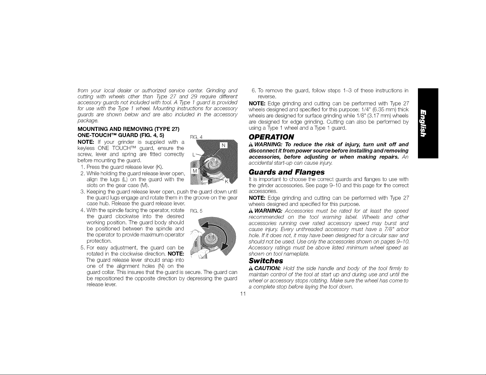
MOUNTING AND REMOVING (TYPE 27)
ONE-TOUCH TM GUARD (FIG. 4, 5) FIG 4
NOTE: If your grinder is supplied with a
keyless ONE TOUCH TM guard, ensure the
screw, lever and spring are fitted correctly
before mounting the guard.
1. Press the guard release lever (K).
2. While holding the guard release lever open,
align the lugs (L) on the guard with the
slots on the gear case (M).
3. Keeping the guard release lever open, push the guard down until
the guard lugs engage and rotate them in the groove on the gear
case hub. Release the guard release lever.
4. With the spindle facing the operator, rotate FIG.5
the guard clockwise into the desired
working position. The guard body should
be positioned between the spindle and
the operator to provide maximum operator
protection.
5. For easy adjustment, the guard can be
rotated in the clockwise direction. NOTE"
The guard release lever should snap into
one of the alignment holes (N) on the
guard collar. This insures that the guard is secure. The guard can
be repositioned the opposite direction by depressing the guard
release lever.
6. To remove the guard, follow steps 1-3 of these instructions in
reverse.
NOTE" Edge grinding and cutting can be performed with Type 27
wheels designed and specified for this purpose; 1/4" (6.35 ram) thick
wheels are designed for surface grinding while 1/8" (3.17 ram) wheels
are designed for edge grinding. Cutting can also be performed by
using a Type 1 wheel and a Type 1 guard.
OPERATION
i_ WARNING: To reduce the risk of injury, turn unit off and
disconnect it from power source before installing and removing
accessories, before adjusting or when making repairs. An
accidental start-up can cause injury.
Guards and Flanges
It is important to choose the correct guards and flanges to use with
the grinder accessories. See page 9-10 and this page for the correct
accessories.
NOTE" Edge grinding and cutting can be performed with Type 27
wheels designed and specified for this purpose.
i_,WARNING: Accessories must be rated for at least the speed
recommended on the tool warning label Wheels and other
accessories running over rated accessory speed may burst and
cause injury. Every unthreaded accessory must have a 7/8" arbor
hole. If it does not, it may have been designed for a circular saw and
should not be used. Use only the accessories shown on pages 9-10.
Accessory ratings must be above listed minimum wheel speed as
shown on tool nameplate.
Switches
A CAUTION: Hold the side handle and body of the tool firmly to
maintain control of the tool at start up and during use and until the
wheel or accessory stops rotating. Make sure the wheel has come to
a complete stop before laying the tool down.
11
Page 13

NOTE: To reduce unexpected tool movement, do not switch the
tool on or off while under load conditions. Allow the grinder to run
up to full speed before touching the work surface. Lift the tool from
the surface before turning the tool off. Allow the tool to stop rotating
before putting it down.
PADDLE SWITCH (DWE4120, DWE4120N) (FIG. 6)
A CAUTION: Before connecting the tool to apower source depress
and release the paddle switch (H) to ensure that the switch is off..
Depress and release the paddle switch as described above after any
interruption in power supply to the tool, such as the activation of a
ground fault interrupter, throwing of a circuit breaker, accidental
unplugging, or power failure.
To turn the tool on, push the lock-off FIG.6
lever (J) toward the back of the tool,
then depress the paddle switch (H).
The tool will run while the switch is
depressed. Turn the tool off by H
releasing the paddle switch. J
WARNING: Do not disable the Iock-off lever. If the Iock-off lever is
disabled, the tool may start unexpectedly when it is laid down.
SLIDER SWITCH (FIG. 7) FIG.7
_t,WARNING: Before connecting the
tool to a power supply, be sure the
slider switch is in the off position by
pressing the rear part of the switch
and releasing. Ensure the slider switch G
is in the off position as described
above after any interruption in power
supply to the tool, such as the activation of a ground fault interrupter,
throwing of a circuit breaker, accidental unplugging, or power failure.
Ifthe slider switch is locked on when the power is connected, the tool
will start unexpectedly,
To start the tool, slide the ON/OFF slider switch (G)toward the front of
the tool. To stop the tool, release the ON/OFF slider switch.
For continuous operation, slide the switch toward the front of the
tool and press the forward part of the switch inward. To stop the tool
while operating in continuous mode, press the rear part of the slider
switch and release.
LOCK-ON BUTTON (DWE4120) (FIG. 8}
The lock-on button (I) offers increased comfort in extended use
applications. To lock the tool on, push the FIG.8
lock-off lever (J) toward the back of the
tool then depress the paddle switch (H).
With the tool running, depress the lock-
on button (I).The tool will continue to run
after the paddle switch is released. To
unlock the tool, depress and release the H j I
paddle switch. This will cause the tool to
stop.
i_ CAUTION: Allow the tool to reach full speed before touching tool
to the work surface. Lift the tool from the work surface before turning
the tool off.
SPINDLE LOCK (FIG. 9)
The spindle lock button (A) is provided to FIG.9
prevent the spindle from rotating when
installing or removing wheels. Operate the
spindle lock only when the tool is turned off,
unplugged from the power supply, and has
come to a complete stop. Do not engage
the spindle lock button while the tool is
operating because damage to the tool will result. To engage the lock,
depress the spindle lock button and rotate the spindle until you are
unable to rotate the spindle further.
12
A
Page 14

Mounting and Using Depressed Center
Grinding Wheels and Sanding Flap Discs
MOUNTING AND REMOVING HUBBED WHEELS (FIG. 10)
Hubbed wheels install directly on the 5/8"-11 FIG.10
threaded spindle. Thread of accessory must D
match thread of spindle.
1. Remove backing flange (D) by pulling B
away from the tool.
2. Thread the wheel on the spindle (B) by
hand.
3. Depress the spindle lock button and use
a wrench to tighten the hub of the wheel.
4. Reverse the above procedure to remove
the wheel. E_
NOTICE: Failure to properly seat the wheel
betore turning the tool on may result in 1/4" WHEELS
damage to the tool or the wheel (6.35mm)
MOUNTING NON-HUBBED WHEELS
(FIG. 10} OlampNut
Depressed center Type 27 grinding wheels
must be used with included flanges. Refer
to Accessories and Attachments for more
information.
1. Installthe backing flange (D)on spindle (B)
with the raised section (pilot) against the
wheel. Be sure the backing flange recess
is seated onto the flats of the spindle by
pushing and twisting the flange before
placing wheel.
Backing Flange
1/8" WHEELS
(3.17 mm)
Clamp Nut
Backing Flange
2. Place wheel against the backing flange, centering the wheel on
the raised section (pilot) of the backing flange.
3. While depressing the spindle lock button, thread the clamp
nut (E)on spindle. Ifthe wheel you are installing is more than 1/8"
(3.17 mm) thick, place the threaded clamp nut on the spindle so
that the raised section (pilot) fits into the center of the wheel. If
the wheel you are installing is 1/8" (3.17 mm) thick or less, place
the threaded clamp nut on the spindle so that the raised section
(pilot) is not against the wheel.
4. While depressing the spindle lock button, tighten the clamp nut
with a wrench.
5. To remove the wheel, depress the spindle lock button and loosen
the threaded clamp nut with a wrench.
NOTE: If the wheel spins after the clamp nut is tightened, check the
orientation of the threaded clamp nut. If a thin wheel is installed with
the pilot on the clamp nut against the wheel, it will spin because the
height of the pilot prevents the clamp nut from holding the wheel.
SURFACE GRINDING WITH GRINDING WHEELS (FIG. 11)
1. Allow the tool to reach full speed before touching the tool to the
work surface.
2. Apply minimum pressure to the work surface, allowing the tool
to operate at high speed. Grinding rate is greatest when the tool
operates at high speed.
3. Maintain a 20° to 30° angle between the
tool and work surface.
4. Continuously move the tool in a forward
and back motion to avoid creating
gouges in the work surface.
5. Remove the tool from work surface before turning tool off. Allow
the tool to stop rotating before laying it down.
13
Page 15
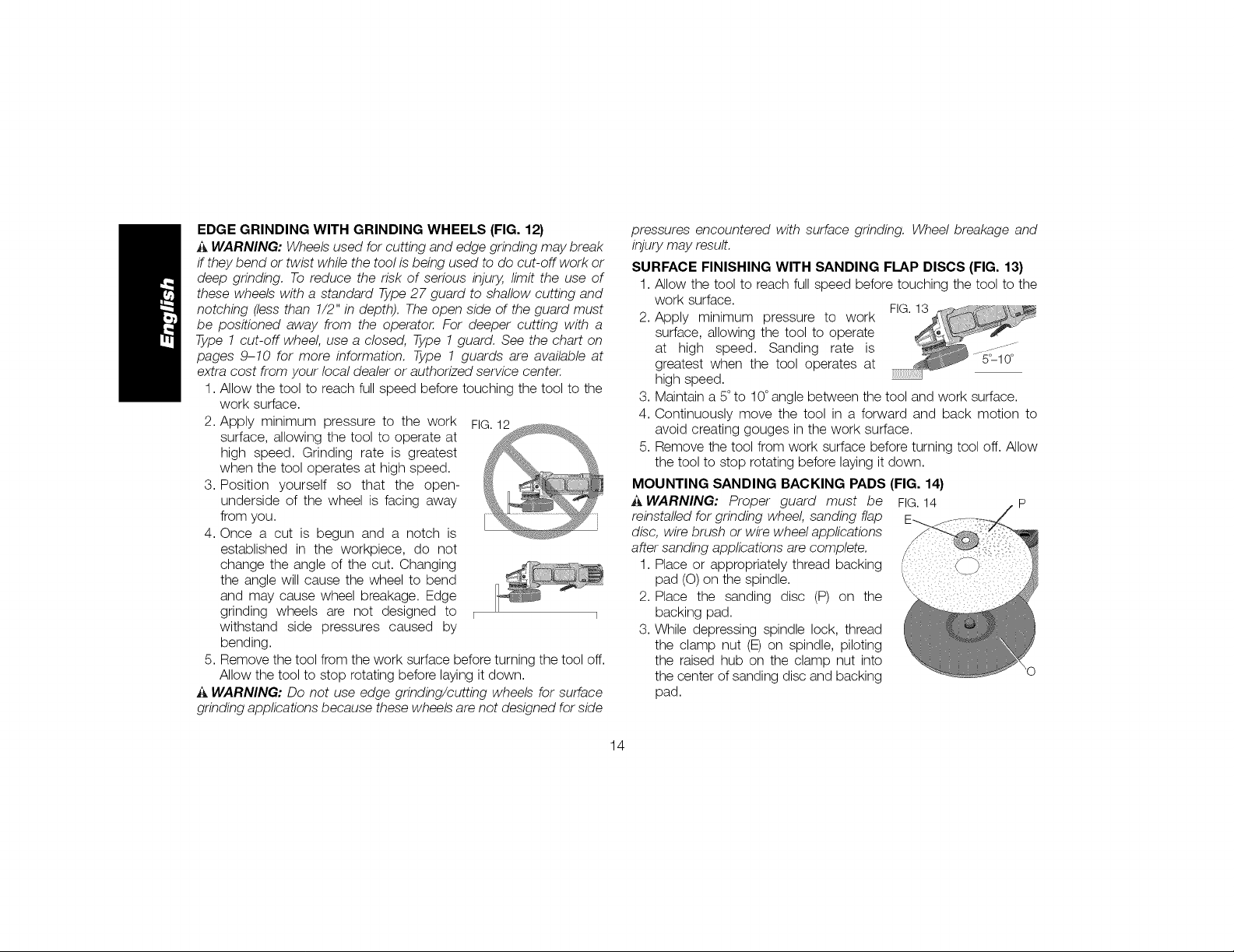
EDGE GRINDING WITH GRINDING WHEELS (FIG. 12)
_ WARNING: Wheels used for cutting and edge grinding may break
if they bend or twist while the tool is being used to do cut-off work or
deep grinding. To reduce the risk of serious injury, limit the use of
these wheels with a standard Type 27 guard to shallow cutting and
notching (less than 1/2" in depth). The open side of the guard must
be positioned away from the operator. For deeper cutting with a
Type 1 cut-off wheel, use a closed, Type 1 guard. See the chart on
pages 9-10 for more information. Type 1 guards are available at
extra cost from your local dealer or authorized service center.
1. Allow the tool to reach full speed before touching the tool to the
work surface.
2. Apply minimum pressure to the work FIG.12
surface, allowing the tool to operate at
high speed. Grinding rate is greatest
when the tool operates at high speed.
3. Position yourself so that the open-
underside of the wheel is facing away
from you.
4. Once a cut is begun and a notch is
established in the workpiece, do not
change the angle of the cut. Changing
the angle will cause the wheel to bend
and may cause wheel breakage. Edge
grinding wheels are not designed to _
withstand side pressures caused by
bending.
5. Remove the tool from the work surface before turning the tool off.
Allow the tool to stop rotating before laying it down.
A WARNING: Do not use edge grinding/cutting wheels for surface
grinding applications because these wheels are not designed for side
pressures encountered with surface grinding. Wheel breakage and
injury may result.
SURFACE FINISHING WITH SANDING FLAP DISCS (FIG. 13)
3. Allow the tool to reach full speed before touching the tool to the
work surface.
2. Apply minimum pressure to work
surface, allowing the tool to operate
at high speed. Sanding rate is
greatest when the tool operates at
high speed.
3. Maintain a 5° to 10°angle between the tool and work surface.
4. Continuously move the tool in a forward and back motion to
avoid creating gouges in the work surface.
5. Remove the tool from work surface before turning tool off. Allow
the tool to stop rotating before laying it down.
MOUNTING SANDING BACKING PADS (FIG. 14}
A WARNING: Proper guard must be FIG. 14 P
reinstalled for grinding wheel, sanding flap
disc, wire brush or wire wheel applications
after sanding applications are complete.
1. Place or appropriately thread backing
pad (O) on the spindle.
2. Place the sanding disc (P) on the
backing pad.
3. While depressing spindle lock, thread
the clamp nut (E) on spindle, piloting
the raised hub on the clamp nut into
the center of sanding disc and backing
pad.
14
Page 16
4.Tightentheclampnutbyhand.Thendepressthespindlelock
buttonwhileturningthesandingdiscuntilthesandingdiscand
clampnutaresnug.
5.Toremovethewheel,graspandturnthebackingpadand
sandingpadwhiledepressingthespindlelockbutton.
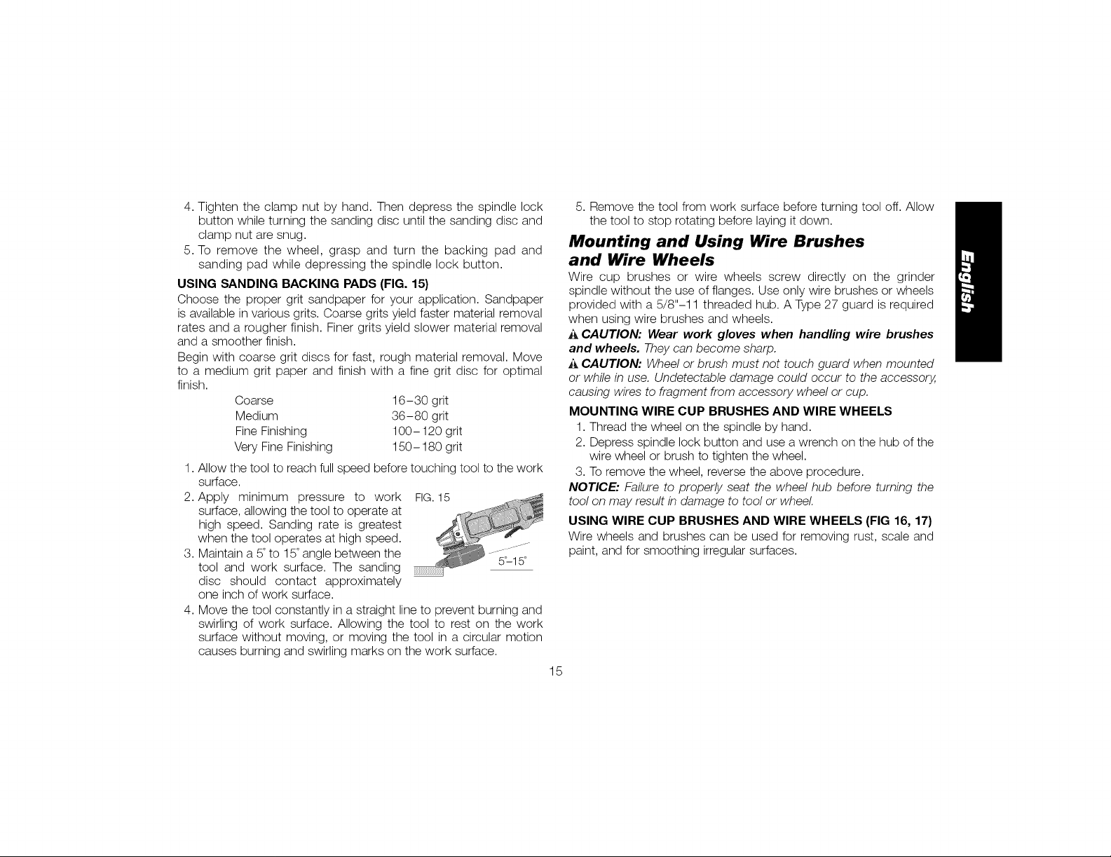
USING SANDING BACKING PADS (FIG. 15)
Choose the proper grit sandpaper for your application. Sandpaper
is available in various grits. Coarse grits yield faster material removal
rates and a rougher finish. Finer grits yield slower material removal
and a smoother finish.
Begin with coarse grit discs for fast, rough material removal. Move
to a medium grit paper and finish with a fine grit disc for optimal
finish.
Coarse 16-30 grit
Medium 36-80 grit
Fine Finishing 100- 120 grit
Very Fine Finishing 150-180 grit
1. Allow the tool to reach full speed before touching tool to the work
surface.
2. Apply minimum pressure to work FIG.15
surface, allowing the tool to operate at
high speed. Sanding rate is greatest
when the tool operates at high speed.
3. Maintain a 5°to 15°angle between the ...........
tool and work surface. The sanding 5_15°
disc should contact approximately
one inch of work surface.
4. Move the tool constantly in a straight line to prevent burning and
swirling of work surface. Allowing the tool to rest on the work
surface without moving, or moving the tool in a circular motion
causes burning and swirling marks on the work surface.
5. Remove the tool from work surface before turning tool off. Allow
the tool to stop rotating before laying it down.
Mounting and Using Wire Brushes
and Wire Wheels
Wire cup brushes or wire wheels screw directly on the grinder
spindle without the use of flanges. Use only wire brushes or wheels
provided with a 5/8"-11 threaded hub. A Type 27 guard is required
when using wire brushes and wheels.
CAUTION: Wear work gloves when handling wire brushes
and wheels. They can become sharp.
A CAUTION: Wheel or brush must not touch guard when mounted
or while in use. Undetectable damage could occur to the accessory,
causing wires to fragment from accessory wheel or cup.
MOUNTING WIRE CUP BRUSHES AND WIRE WHEELS
1. Thread the wheel on the spindle by hand.
2. Depress spindle lock button and use a wrench on the hub of the
wire wheel or brush to tighten the wheel.
3. To remove the wheel, reverse the above procedure.
NOTICE: Failure to properly seat the wheel hub before turning the
tool on may result in damage to tool or wheel
USING WIRE CUP BRUSHES AND WIRE WHEELS (FIG 16, 17)
Wire wheels and brushes can be used for removing rust, scale and
paint, and for smoothing irregular surfaces.
15
Page 17

1.AllowthetooltoreachfullspeedbeforeFIG.16
touchingthetooltotheworksurface.
2.Applyminimumpressuretoworksurface,
allowingthetoolto operateat high
speed.Materialremovalrateisgreatest
whenthetooloperatesathighspeed.
3.Maintaina5°to10°anglebetweenthetoolandworksurfacefor
wirecupbrushes.
4.Maintaincontactbetweentheedgeofthewheelandthework
surfacewithwirewheels.
5.Continuouslymovethetoolinaforwardand FIG.17
backmotiontoavoidcreatinggougesinthe
worksurface.Allowingthetooltorestonthe
worksurfacewithoutmoving,ormovingthe
toolinacircularmotioncausesburningand
swirlingmarksontheworksurface.
6.Removethetoolfromtheworksurfacebeforeturningthetooloff.
Allowthetooltostoprotatingbeforesettingitdown.
,_ CAUTION: Use extra care when working over an edge, as a
sudden sharp movement of grinder may be experienced.
Mounting and Using Cutting
(Type 1) Wheels
Cutting wheels include diamond wheels and abrasive discs. Abrasive
cutting wheels for metal and concrete use are available. Diamond
blades for concrete cutting can also be used.
A WARNING: A closed, 2-sided cutting wheel guard is not included
with this tool but is required when using cutting wheels. Failure to use
proper flange and guard can result in injury resulting from wheel
breakage and wheel contact. See page 10 for more information.
MOUNTING CLOSED (TYPE 1) GUARD (FIG. 18-20)
_ WARNING: If present, the ONE TOUCHTM guard screw, lever and
spring must be removed before attempting to mount the closed
(Type 1) guard. The removed parts must be retained and reinstalled
to use the ONE TOUCHTM guard. Noting the position of these parts
before disassembly will aid in reassembly.
1. Open the guard latch (Q). Align the FIG.18
lugs (L) on the guard with the slots
(M) on the gear case. M
2. Push the guard down until the guard
lug engages and rotates freely in
the groove on the gear case hub.
3. Rotate guard (F) into desired
working position. The guard body
should be positioned between the L
spindle and the operator to provide Q
nlaximum operator protection.
4. Close the guard latch to secure the FIG.19
guard on the gear case cover. You
should be unable to rotate the guard by
hand when the latch is in closed
position. If rotation is possible, tighten
the adjusting screw (R)with clamp lever
in the closed position. Do not operate F
grinder with a loose guard or clamp
lever in open position.
5,
To remove the guard, open the guard latch, rotate the guard so
that the arrows are aligned and pull up on the guard.
16
Page 18

NOTE: If, after a period of time the closed (Type 1) FIG.20
guard becomes loose, tighten the adjusting
screw (R) with the clamp lever in the closed R
position.
NOTICE: Do not tighten adjusting screw with
clamp lever in open position. Undetectable
damage to guard or mounting hub may result.
CAUTION: If the guard cannot be tightened by the adjusting clamp,
do not use the tool To reduce the risk of personal injury, take the tool
and guard to an authorized service center to repair or replace the
guard.
MOUNTING CUTTING WHEELS
A CAUTION: Matching diameter threaded backing flange and clamp
nut (included with tool) must be used for cutting wheels.
1. Place the unthreaded backing flange on spindle with the raised
section (pilot) facing up. The raised section (pilot) on the backing
flange will be against the wheel when the wheel is installed.
2. Place the wheel on the backing flange, centering the wheel on the
raised section (pilot).
3. Install the threaded clamp nut with the raised section (pilot)
facing away from the wheel.
4. Depress the spindle lock button and tighten clamp nut with a
wrench.
5. To remove the wheel, grasp and turn while depressing the
spindle lock button.
USING CUTTING WHEELS (FIG. 21)
_, WARNING: Do not use edge grinding/cutting wheels for surface
grinding applications because these wheels are not designed for side
pressures encountered with surface grinding. Wheel breakage and
injury may result.
1. Allow tool to reach full speed before FIG.21
touching tool to work surface.
2. Apply minimum pressure to work
surface, allowing tool to operate at
high speed. Cutting rate is greatest
when the tool operates at high speed.
3. Once a cut is begun and a notch is
established in the workpiece, do not
change the angle of the cut. Changing
the angle will cause the wheel to bend
and may cause wheel breakage.
4. Remove the tool from work surface
before turning tool off. Allow the tool to
stop rotating before setting it down.
MAINTENANCE
A WARNING: To reduce the risk of injury, turn unit off and
disconnect it from power source before installing and removing
accessories, before adjusting or when making repairs. An
accidental start-up can cause injury,
Cleaning
WARNING: Blow dirt and dust out of all air vents with clean, dry air
at least once a week. To minimize the risk of eye injury, always wear
ANSI Z87.1 approved eye protection when performing this.
A WARNING: Never use solvents or other harsh chemicals for
cleaning the non-metallic parts of the tool These chemicals may
weaken the plastic materials used in these parts. Use a cloth
dampened only with water and mild soap. Never let any liquid get
inside the tool,"never immerse any part of the tool into a liquid.
17
Page 19

Accessories
_ WARNING: Since accessories, other than those offered by
DEWALT, have not been tested with this product, use of such
accessories with this tool could be hazardous. To reduce the risk of
injury, only DEWALTrecommended accessories should be used with
this product.
Recommended accessories for use with your tool are available at
extra cost from your local dealer or authorized service center. If you
need assistance in locating any accessory, please contact DEWALT
Industrial Tool Co., 701 East Joppa Road, Baltimore, MD 21286,
call 1-800-4-DEWALT (1-800-433-9258) or visit our website: www.
DEiWALT.com.
Repairs
To assure product SAFETY and RELIABILITY, repairs, maintenance
and adjustment (including brush inspection and replacement) should
be performed by a DEiWALT factory service center, a DEWALT
authorized service center or other qualified service personnel. Always
use identical replacement parts.
Register Online
Thank you for your purchase. Register your product now for:
• WARRANTY SERVICE: Registering your product will help you
obtain more efficient warranty service in case there is a problem
with your product.
• CONFIRMATION OF OWNERSHIP: In case of an insurance
loss, such as fire, flood or theft, your registration of ownership will
serve as your proof of purchase.
• FOR YOUR SAFETY: Registering your product will allow us to
contact you in the unlikely event a safety notification is required
under the Federal Consumer Safety Act.
Register online at www.dewalt.com/register.
Three Year Limited Warranty
DEiWALTwill repair, without charge, any defects due to faulty materials
or workmanship for three years from the date of purchase. This
warranty does not cover part failure due to normal wear or tool
abuse. For further detail of warranty coverage and warranty repair
information, visit www.dewalt.com or call 1-800-4-DF-:WALT (1-800-
433-9258). This warranty does not apply to accessories or damage
caused where repairs have been made or attempted by others. This
warranty gives you specific legal rights and you may have other rights
which vary in certain states or provinces.
Inaddition to the warranty, DEiWALTtools are covered by our:
1 YEAR FREE SERVICE
DEiWALTwill maintain the tool and replace worn parts caused by
normal use, for free, any time during the first year after purchase.
90 DAY MONEY BACK GUARANTEE
If you are not completely satisfied with the performance of your
DEWALTPower Tool, Laser, or Nailer for any reason, you can return
it within 90 days from the date of purchase with a receipt for a full
refund - no questions asked.
LATIN AMERICA: This warranty does not apply to products sold
in Latin America. For products sold in Latin America, see country
specific warranty information contained in the packaging, call the
local company or see website for warranty information.
18
Page 20

FREE WARNING LABEL REPLACEMENT: If your warning labels
become illegible or are missing, call 1-800-4-DEWALT (1-800-433-
9258) for a free replacement.
_WE×X×...................................................._;,,:i;;_.,;_.....................................................................................................
I ...............................l
MAXIMUg SPEEDMARKEDONTHE TOOL.ALWAYSUSEPROPERGUARDS
....................................................1
W_EN g_IN_ING_ESpI_ATO_y PROT[CTIQ_,
R_A0INST_UCTIONaANUAL A_WAVSwE_
_ t_ERELMANUALDE
I_STRU_CID_ES,CONELFI_ DEREDUCIR_LRIESGODE
_SlONES. SI_MP_Eaw_ p_OT_CrlONOCUlAr.SOLD
UTlUCEACC_S0el0SC_YAVELOCl0aDN0glNa_ S_
,V.ME,_OSEaUZWLE,_TEa L_WLOCID_D _,L_M_
It_BICADAEN LAH_NI_m_. u_luc_ sl_P_ _os
PROTEffrORESAI'ROI_I_DO5CIIAflD0 REALICE
O_E_ClO_I_S OEPUtZDO.I_W SlEMP_ _OTE_ClO_
_ESPIR_T0_IA_pRON_I_. FOUR _I_D_I_
DEDOMN_£S _0RPOREL$,_UTltlSATEUR_0]T tJg£tE
_NU_L _E _OTIIISaT_O_._ORTER
OTIBSE_fEXCLIISIV£MENTO£S_eC_SSOI_ES _Or_Tt_
A eEUEIN_I_O_E gUR t'OU_t, UntlS_R
_RDTECTIOt__ VOLESRES_aTOIRESA_aV_TES,
Et UgUARIO_EBE
TOVT _l_OO_
19
Page 21
D_finitions : lignes directrices en
mati_re de s_curit_
Les definitions ci-dessous decrivent le niveau de danger pour
chaque mot-indicateur employe. Lire le mode d'emploi et porter
une attention particuliere a.ces symboles.
i_ DANGER : indique une situation dangereuse imminente qui,
si elle n'est pas evitee, entraTnera la mort ou des blessures
graves.
_AVERTISSEMENT : indique une situation potentie//ement
dangereuse qui, si e//e n'est pas evitee, pourrait entra_ner /a
mort ou des blessures graves.
i_ATTENTION : indique une situation potentie//ement
dangereuse qui, si el/e n'est pas evitee, pourrait entra_ner des
blessures I_g_res ou modifies.
AVIS : indique une pratique ne posant aucun risque de
dommages corporels mais qui par contre, si rien n'est fair
pour /'eviter, pourrait poser des risques de dommages
materiels.
J
POUR TOUTE QUESTION OU REMARQUE AU SUJET DE CET
OUTIL OU DE TOUT AUTRE OUTIL DEWALT, COMPOSE LE
NUMFt:ROSANS FRAIS : 1-800-4-DEWALT (1-800-433-9258}.
_ VERTISSEMENT afin de reduire le risque de blessures, life
le mode d'emploi de I'outil.
Avertissements de s_curit_ g_n_raux
pour les outils _lectriques
s_curit_ et toutes les directives. Le non-respect des
_k AVERTISSEMENT ! Life tousles avertissements de
avertissements et des directives pourrait se solder par un
choc dectrique, un incendie et/ou une blessure grave.
CONSERVER TOUSLES AVERTISSEMENTS
ET TOUTES LES DIRECTIVES POUR UN
USAGE ULTERIEUR
Le terme _ outil dectrique _ cite dans les avertissements se rapporte
votre outil electrique a alimentation sur secteur (avec ill) ou par piles
(sansfi/).
1) S#CURIT# DU LIEU DE TRAVAIL
a) Ten#" I'aire de travail propre et bien _clair_e. /es Iieux
encombres ou sombres sont propices aux accidents.
b) Ne pas faire fonctionner d'outils _lectriques clans un
milieu d_flagrant, tel qu'en presence de liquides, de
gaz ou de poussi_res inflammables. Les outi/s e/ectriques
produisent des etincelles qui pourraient enflammer la poussiere
ou les vapeurs.
c) E-Ioigner les enfants et les personnes a proximit_ pendant
I'utilisation d'un outil _lectrique. Une distraction pourrait en
faire perdre la ma_trisea I'utilisateur.
2) SI_CURITI_ EN MATI#RE D'I_LECTRICITI_
a) Les fiches des outils _lectriques doivent correspondre
la prise. Ne jamais modifier la fiche d'aucune faqon.
Ne jamais utiliser de fiche d'adaptation avec un outil
_lectrique mis a la terre. Le risque de choc dectrique sera
reduit par I'utilisation de fiches non modifiees correspondant
la prise.
2O
Page 22

b)Eviter tout contact physique avec des surfaces mises a la
terre comme des tuyaux, des radiateurs, des cuisini_res
et des r_frig_rateurs. Le risque de choc dectrique est plus
deve si votre corps est mis a la terre.
c) Ne pas exposer les outils _lectriques a la pluie ou
I'humidit_. La penetration de /'eau dans un outi/ dectrique
augmente le risque de choc dectrique.
d) Ne pas utiliser le cordon de fa_on abusive. Ne jamais
utiliser le cordon pour transporter, tirer ou d_brancher
un outil _lectrique. Tenir le cordon _loign_ de la chaleur,
de rhuile, des bords tranchants et des pi_ces mobiles.
Les cordons endommages ou enchev_tres augmentent les
risques de choc dectrique.
e) Pour I'utilisation d'un outil _lectrique a I'ext_rieur, se
servir d'une rallonge convenant a cette application.
L'utilisation d'une rallonge conque pour I'exterieur reduira les
risques de choc dectrique.
S'il est impossible d'_viter I'utilisation d'un outil
_lectrique dans un endroit humide, brancher routil dans
une prise ou sur un circuit d'alimentation dot_s d'un
disjoncteur de fuite a la terre (GFCI). L'utilisation de ce type
de disjoncteur reduit les risques de choc dectrique.
3) SI_CURITI_ PERSONNELLE
a) Etre vigilant, surveiller le travail effectu_ et faire preuve
de jugement Iorsqu'un outil _lectrique est utilis_. Ne
pas utiliser d'outil _lectrique en cas de fatigue ou sous
I'influence de drogues, d'alcool ou de m_dicaments. Un
simple moment d'inattention en utilisant un outil dectrique peut
entra_nerdes blessures corporelles graves.
b) Utiliser des _quipements de protection individuelle.
Toujours porter une protection oculaire. L'utilisation
d'equipements de protection comme un masque antipoussiere,
des chaussures antiderapantes, un casque de securite ou des
protecteurs auditifs Iorsque la situation le requiert reduira les
risques de blessures corporelles.
c) Emp_cher les d_marrages intempestifs. S'assurer que
I'interrupteur se trouve a la position d'arr_t avant de
relier I'outil a une source d'alimentation et/ou d'ins_rer
un bloc-piles, de ramasser ou de transporter I'outil.
Transporter un outil dectrique alors que le doigt repose sur
I'interrupteur ou brancher un outil dectrique dont I'interrupteur
est a la position de marche risque de provoquer un accident.
d) Retirer toute cl_ de r_glage ou cl_ avant de d_marrer
I'outil. Une c/e ou une c/e de reg/age attachee a une partie
pivotante de I'outil dectrique peut provoquer des blessures
corporelles.
e) Ne pas trop tendre les bras. Conserver son _quilibre en
tout temps. Ce/a permet de mieux ma_triser /'outi/ dectrique
dans les situations imprevues.
S'habiller de mani_re appropri_e. Ne pas porter de
v_tements amples ni de bijoux. Garder les cheveux, les
v_tements et les gants a I'_cart des pi_ces mobiles. Les
v_tements amp/es, /es bijoux ou /es cheveux longs risquent de
rester coinces dans les pieces mobiles.
g) Si des composants sent fournis pour le raccordement de
dispositifs de d_poussi_rage et de ramassage, s'assurer
que ceux-ci sent bien raccord_s et utilis_s. L'utilisation
d'un dispositif de depoussierage peut reduire les dangers
engendres par les poussieres.
21
Page 23

4) UTILISATION ET ENTRETIEN D'UN OUTIL #LECTRIQUE
a) Ne pas forcer un outil _lectrique. Utiliser I'outil _lectrique
appropri_ a I'application. L'outil dectrique approprie
effectuera un meilleur travail, de faqon plus sore eta la vitesse
pour laquelle il a ete conqu.
b) Ne pas utiliser un outil _lectrique dont I'interrupteur
est d_fectueux. Tout outil dectrique dont I'interrupteur est
defectueux est dangereux et doit _tre repare.
c) D_brancher la fiche de la source d'alimentation et/ou du
bloc-piles de I'outil _lectrique avant de faire tout r_glage
ou changement d'accessoire ou avant de ranger I'outil.
Ces mesures preventives reduisent les risques de demarrage
accidentel de I'outil dectrique.
d) Ranger les outils _lectriques hors de la pottle des
enfants et ne permettre a aucune personne n'_tant
pas famili_re avec un outil _lectrique ou son mode
d'emploi d'utiliser cet outil. Les out//s e/ectr/ques dev/ennent
dangereux entre les mains d'utilisateurs inexperimentes.
e) Entretien des outils _lectriques. V_rifier si les pi_ces
mobiles sont mal align_es ou coinc_es, si des pi_ces sont
bris_es ou pr_sentent toute autre condition susceptible
de nuire au bon fonctionnement de I'outil _lectrique.
En cas de dommage, faire r_parer I'outil _lectrique
avant toute nouvelle utilisation. Beaucoup d'accidents sont
causes par des outils dectriques mal entretenus.
S'assurer que les outils de coupe sont aiguis_s et
propres. Les outils de coupe bien entretenus et affOtes
sont moins susceptibles de se coincer et sont plus faciles
ma_triser.
g) Utiliser I'outil _lectrique, les accessoires, les forets,
etc. conform_ment aux pr_sentes directives en tenant
compte des conditions de travail et du travail _ effectuer.
L'utilisation d'un outil dectrique pour toute operation autre que
celle pour laquelle il a ete conqu est dangereuse.
5) RI_PARATION
a) Faire r_parer I'outil _lectrique par un r_parateur
professionnel en n'utilisant que des pi_ces de rechange
identiques. Cela permettra de maintenir une utilisation
securitaire de I'outil dectrique.
CONSIGNES DE SECURITE POUR
TOUTES LES OPERATIONS
Avertissements de sdcuritd communs
toutes les opdrations de meulage,
pon_;age, brossage _ I'aide d'une brosse
mdtallique, polissage ou de coupe
a) Cet outil _lectrique est con_u pour fonctionner comme
une meule, une ponceuse, une brosse m_tallique,
une polisseuse ou un outil de coupe. Life tous les
avertissements de s_curit_, les directives, les
illustrations et les specifications fournies avec cet outil
_lectrique. Negliger de suivre /'ensemble des directives
suivantes pourrait entra_ner des risques de choc dectrique,
d'incendie et/ou de blessures graves.
b) Ne pas utiliser d'accessoire non conqu sp_cifiquement
pour cet outil ou qui n'aurait pas requ une approbation
sp_cifique du fabricant de I'outil. En effet, i/ est parfois
possible de fixer un accessoire a I'outil dectrique; toutefois,
cela ne garantit pas une utilisation securitaire.
22
Page 24

c) Le r_gime nominal de raccessoire doff _tre au moins
_gal au r_gime maximal inscrit sur I'outil _lectrique. Les
accessoires soumis a un regime plus deve que celui pour
lequel ils sont conqus peuvent se briser et _tre projetes.
d) Le diam_tre externe et I'_paisseur de I'accessoire doivent
_tre ad_quats pour la capacit_ de I'outil _lectrique. //est
impossible de proteger I'utilisateur d'un bris d'accessoire de
mauvais calibre ou de le ma_triser correctement.
e) Le trou pour arbre d'entra_nement des meules, brides,
tampons ou de tout autre accessoire doit s'ajuster
correctement a la broche de I'outil _lectrique; autrement,
I'outil sera desequilibre, vibrera excessivement et risquerait de
provoquer une perte de ma_trise.
Ne jamais utiliser un accessoire endommag_. Avant
toute utilisation, inspecter la meule abrasive a la
recherche d'_clats et de fissures; le tampon pour tout
signe de fissures, dechirures ou d'usure excessive;
et la brosse m_tallique, pour d_celer s'il y a des ills
m_talliques fissures ou d_tach_s. En cas de chute de
I'outil ou de I'accessoire, les inspecter a la recherche de
dommages ou insurer un accessoire non endommag_.
Apr_s I'inspection et rinsertion d'un accessoire, se
positionner (l'utilisateur ou quiconque aux alentours)
hors du plan de rotation de I'accessoire et faire tourner,
pendant une minute, I'outil _lectrique a plein r_gime,
vide. Normalement, tout accessoire endommage se brisera au
cours de cette periode d'essaL
g) Porter un _quipement de protection individuelle. Utiliser
un masque facial, des lunettes de s_curit_ ou des
lunettes protectrices en fonction de I'application. Au
besoin, porter un masque antipoussi_res, des protecteurs
auditifs, des gants et un tablier d'atelier capable d'arr_ter
de petits fragments d'abrasifs ou de pi_ces. La protection
oculaire doit _tre en mesure d'arr_ter tout debris produit par
les diverses operations et le masque antipoussieres ou le
respirateur, de filtrer les particules produites par I'operation en
cours. Une exposition prolongee a un bruit d'intensite devee
pourrait causer une perte auditive.
h) Eloigner tout observateur a une distance s_curitaire de
la zone de travail. Toute personne qui p_n_tre clans la
zone de travail devra _galement porter un _quipement
de protection individuelle. // est possible qu'un fragment
de piece ou un accessoire brise soit projete et provoque des
blessures au-dela de la zone immediate de travail.
i) Tenir I'outil _lectrique uniquement par sa surface de
prise isol_e clans une situation ob raccessoire de coupe
pourrait entrer en contact avec un c&ble _lectrique
dissimul_ ou avec son propre cordon d'alimentation. Tout
contact de I'organe de coupe avec un fil sous tension met les
parties metalliques exposees de I'outil dectrique sous tension
et dectrocute I'utilisateur.
j) Positionner le cordon d'alimentation hors d'atteinte de
I'accessoire en mouvement. En cas de perte de ma_trise,i/
est possible de couper ou d' effilocher le cordon et la main ou le
bras de I'utilisateur risqueraient d'etre happes par I'accessoire
en mouvement.
k) Nejamais d_poser I'outil_lectrique avant I'immobilisation
complete de raccessoire. L'accessoire en mouvement
risquerait de mordre dans la surface et de projeter I'outil
dectrique.
I) Mettre routil hors tension pour tout d_placement
de celui-ci par I'utilisateur. Un contact accidente/ avec
I'accessoire en mouvement pourrait happer les v_tements de
I'operateur et projeter I'accessoire contre son corps.
23
Page 25

m)Nettoyer r_guli_rement les _vents de I'outil _lectrique.
Le ventilateur du moteur aspirera la poussiere a I'interieur du
boftier. Une accumulation excessive de poudre metallique
represente un danger d'origine dectrique.
n) Ne pas faire fonctionner I'outil _lectrique a proximit_ de
mati_res inflammables. Les etince//es produites risquent de
/es enflammer.
o) Ne pas utiliser d'accessoires qui exigent I'utilisation
d'un liquide de refroidissement. L'uti/isation d'eau ou de
tout autre liquide de refroidissement pourrait se solder par une
dectrocution ou une secousse dectrique.
Rebonds et avertissements aff_rents
L'effet de rebond est une reaction soudaine d'une meule,
d'un tampon, d'une brosse ou d'un tout autre accessoire, en
mouvement, qui est pince ou qui s'accroche. Un pincement
ou un accrochage provoque un arr_t rapide de I'accessoire en
mouvement qui, a son tour, projette I'outil dectrique, hors de
ma_trise,dans la direction opposee a la rotation de I'outil au point
de grippage.
Par exemple, si une meule abrasive se pince ou s'accroche clans
la piece, le bord de la meule introduite au point de pincement peut
mordre dans la surface de la piece et projeter la meule hors de la
rainure. La meule peut _tre projetee vers I'operateur ou dans la
direction opposee selon le sens de rotation de la meule au point
de pincement. II est egalement possible que les meules abrasives
se brisent dans ces conditions.
Les rebonds proviennent d'une utilisation inadequate de I'outil
dectrique et/ou d'une procedure ou de conditions d'utilisation
incorrectes, et peuvent _tre evites en prenant les precautions
appropriees detaillees ci-apres :
a) Saisir fermement I'outil _lectrique et positionner le
corps et les bras de sorte a r_sister a la force de I'effet
de rebond. Utiliser toujours la poign_e auxiliaire, s'il y
en a une, pour contr61er au maximum I'effet de rebond
ou le couple de r_action au d_marrage. Avec de bonnes
precautions, I'operateur est en mesure de contr61er le couple
de reaction ou I'effet de rebond.
b) Ne jamais placer les mains pros de I'accessoire en
mouvement. // pourrait en effet _tre projete sur ce//es-ci en cas
de rebond.
c) Ne pas positionner le corps clans la trajectoire probable
de I'outil _lectrique, en cas de rebond. Au moment du
grippage, I'outil sera projete dans la direction opposee au
deplacement de la meule.
d) Etre particuli_rement attentif lots de travaux clans un
coin, sur des bords tranchants, etc. Eviter de faire
rebondir I'accessoire. _:viter tout type de grippage de
I'accessoire. Un travail dans un coin ou sur des bords
tranchants ou un travail en faisant rebondir I'accessoire
provoquent souvent un grippage et une perte de ma_trise de
I'outil ou un effet de rebond.
e) Ne pas fixer de lame de tron_onneuse pour sculpter
le bois ou de lame de scie dent_e. Ces types de lames
provoquent des effets de rebond et des pertes de ma_trise
frequents.
Avertissements de s_curit_ sp_cifiques
aux opdrations de meulage et de coupe
par abrasion
a) Utiliser uniquement les types de meules recommand_s
pour I'outil _lectrique ainsi que le capet protecteur
particulier conqu pour la meule s_lectionn_e. // est
24
Page 26

impossibledebienprotegerI'operateurlotsdeI'utilisationde
meulesnonconquespourI'outil.Eneffet, le capot protecteur
sera alors inadequat et I'utilisation de la meule, dangereuse.
b) II faut fixer solidement le capet protecteur a I'outil
_lectrique et le positionner pour maximiser la s_curit_ de
I'op_rateur, soit en minimisant la surface expos_e de la
meule en direction de I'op_rateur. Le carter aide a proteger
I'utilisateur contre toute projection de fragments et contre tout
contact accidentel avec la meule, ainsi que de toute etincelle
pouvant enflammer les v_tements.
c) Utiliser uniquement les meules pour les applications
pr_vues pour chacune d'entre elles. Par exemple : ne
pas meuler avec le bord d'une meule tron_onneuse.
Les meules tronqonneuses par abrasion sont conques pour
travailler en peripherie. L'application de forces laterales sur ces
meules risquerait de les faire eclater.
d) Toujours utiliser des brides de meule intactes, de la
bonne dimension et de la forme appropri_e pour la meule
s_lectionn_e. Les brides de meu/e appropriees supportent
bien lameule et reduisent ainsi la possibi/ite d'un bris de meule.
Les brides conques pour les meules tronqonneuses pourraient
differer des brides pour meules a ponqage.
e) Ne pas utiliser de meule us_e en provenance d'outil de
dimension plus importante. Ces meu/es, prevues pour un
outil dectrique plus grand, ne conviennent pas au regime plus
deve d'un outil de plus petite dimension et pourraient eclater.
Avertissements de s_curit_
suppl_mentaires sp_cifiques aux
operations de coupe par abrasion
a) Ne pas _, coincer _, la meule tronqonneuse ou ne pas
appliquer une pression excessive. Ne pas essayer de
couper a une profondeur trop importante. Une contrainte
excessive sur la meule accroftra la charge et la possibilite de
tordre ou de gripper la meule dans le trait de coupe et ainsi
provoquer un effet de rebond ou un bris de la meule.
b) Ne pas positionner le corps sur la trajectoire de la meule
en mouvement ni derriere celle-cL Lorsque /a meu/e,
au point de contact avec la piece, s'doigne du corps de
I'operateur, un effet de rebond potentiel risque de projeter la
meule en rotation, ainsi que I'outil, en direction de I'utilisateur.
c) Lorsque la meule se grippe ou lots de I'arr_t d'une
coupe pour une raison quelconque, mettre I'outil hers
tension et maintenir I'outil immobile jusqu'& I'arr_t
complet de la meule. Ne jamais essayer de retirer la
meule tronqonneuse du traff de coupe alors que celle-ci
est encore en mouvement. Line telle pratique risqueraff
de provoquer un effet de rebond. Rechercher et prendre
I'action corrective necessaire pour diminer les causes du
grippage de la meule.
d) Ne pas reprendre la coupe avec la meule clans le trait
de coupe de la piece. Attendre que la meule soft a plein
r_gime puis la r_ins_rer soigneusement clans le trait de
coupe. Si /'outi/ dectrique redemarrait avec /a meu/e appuyee
sur lapiece, cel/e-ci risquerait de gripper, de se deplacer ou de
reculer.
e) Pour r_duire le risque de pincement ou de recul de
la meule, soutenir les panneaux ou toute autre piece
surdimensionn_e. Les grandes pieces tendent a s'affaisser
sous leur propre poids. Disposer des appuis sous la piece,
le long de la ligne de coupe et pres du bord de la piece, des
deux c6tes de la meule.
25
Page 27
Faire particuli_rement attention Iors de la r_alisation
de _ d_coupe en poche _,dans des murs existants ou
d'autres zones sans visibilitY. La portion de la meule faisant
saillie risque de couper un tuyau d'alimentation en eau ou en
gaz, des ills dectriques ou des objets pouvant provoquer un
effet de rebond.
Avertissements de s_curit_ sp_cifiques
aux operations de pon_;age
a) Ne pas utiliser un papier pour disque abrasif
excessivement surdimensionn_. Respecter les
recommandations des fabricants lots de la s_lection du
papier abrasif. Un papier abrasif plus grand que le plateau de
ponqage represente un risque de laceration. Le papier risque
egalement de s'accrocher, de se dechirer ou de provoquer un
effet de rebond.
Consignes de s_curit_ propres au
polissage
a) Ne laisser aucune portion I_che du bonnet de polissage
ou ses cordons de fixation tourner librement. Dissimu/er
ou couper toute pattie excessive des cordons de fixation. Des
cordons I_ches, en rotation libre, pourraient se prendre dans
les doigts ou s'accrocher a la piece a travailler.
Avertissements de s_curit_ sp_cifiques
aux operations utilisant une brosse
m_tallique
a) Etre attentif, car la brosse peut projeter des soies
m_talliques m_me lots de travaux normaux. Ne pas
surcharger la brosse en appliquant une force excessive
sur celle-ci. Les soies metalliques penetrent facilement les
v_tements legers ou la peau.
b) Si rutilisation d'un capet protecteur est recommand_e
avec la brosse m_tallique, s'assurer qu'il n'interf_re pas
avec la rotation de la brosse m_tallique a touret ou de
la brosse m_tallique. Les meules ou brosses metal/iques
circulaires peuvent se dilater en diametre en raison de la charge
de travail et des forces centrifuges.
R_gles additionnelles de s_curit_ propres
aux meuleuses
_AVERTISSEMENT : la meule ou un accessoire pourrait se
desserrer lots de I'arr_t graduel de I'outil une fois celui-ci mis
hers tension. Si c'etait le cas, la meule ou I'accessoire pourrait se
detacher de I'outil et poser ainsi des risques de dommages corporels
graves.
• II n'est pas recommand_ d'utiliser des accessoires non
indiqu_s dans le present mode d'emploi; cela peut _tre
dangereux. Utiliser des amplificateurs de puissance qui feraient
fonctionner I'outil a une vitesse superieure a sa vitesse nominale
represente une utilisation abusive.
• Utilisez des serres de fixation ou un autre dispositif de
fixation permettant de soutenir et de retenir la piece sur
une plate-forme stable. Tenir la piece avec la main ou contre
son corps n'est pas suffisamment stable et risque de provoquer
une perte de ma_trise de I'outil.
• Eviter de faire rebondir la meule ou de la traiter durement.
Si cela se produit, arr_ter I'outil et inspecter la meule a la recherche
de fissures ou de defauts.
• Manipuler et stocker les meules en prenant systematiquement des
precautions.
26
Page 28

• Ne jamais couper a un endroit pouvant contenir un c_ble
_lectrique ou des tuyaux. II peut en resulter des blessures
graves.
• Ne pas faire fonctionner cet outil durant de Iongues
p_riodes. Les vibrations causees par le fonctionnement de I'outil
peuvent provoquer des blessures permanentes aux doigts, aux
mains et aux bras. Utiliser des gants afin d'amortir davantage les
vibrations, s'arr_ter frequemment et limiter I'utilisation quotidienne
de I'outil.
• Ne jamais utiliser de meules de type 11 (boisseau conique)
sur cet outil. L'utilisation d'accessoires inadequats peut se solder
par des blessures.
• Toujours se servir de la poign_e lat_rale. La fixer solidement.
La poignee laterale doit _tre utilisee pour maRriser I'outil en tout
temps.
• Prendre des precautions a proximit_ des _vents, car ils
cachent des pi_ces mobiles. V_tements amples, bijoux ou
cheveux longs risquent de rester coinces dans ces pieces mobiles.
• Pour la s_curit_ de rutilisateur, utiliser une rallonge de
calibre ad_quat (AWG, American Wire Gauge [calibrage
am_ricain normalis_ des ills _lectriques]). Plus le calibre est
petit, et plus sa capacite est grande. Un calibre 16, par exemple,
a une capacite superieure a un calibre 18. L'usage d'une rallonge
de calibre insuffisant causera une chute de tension qui entra_nera
perte de puissance et surchauffe. Si plus d'une rallonge est utilisee
pour obtenir une certaine Iongueur, s'assurer que chaque rallonge
presente au moins le calibre de filminimum. Le tableau ci-dessous
illustre les calibres a utiliser selon la Iongueur de rallonge et
I'intensite nominale indiquee sur la plaque signaletique. En cas
de doute, utiliser le calibre suivant. Plus le calibre est petit, plus la
rallonge peut supporter de courant.
Calibres minimaux des rallonges
Intensit_
(en amperes)
Sup_rieur Inf_rieur
0 6
6 10
10 12
12 16
Volts Longueur totale de cordon en metres
(pieds)
120V 7,6(25) 15,2(50) 30,5(100) 45,7(150)
240 V 15,2 (50) 30,5 (100) 61,0 (200) 91,4 (300)
AWG
18 16 16 14
18 16 14 12
16 16 14 12
14 12 Nonrecommande
AVERTISSEMENT : porter SYSTEMATIQUEMENT des/unettes
de protection. Les lunettes courantes NE sont PAS des lunettes de
protection. Utiliser aussi un masque antipoussieres si la decoupe doit
en produire beaucoup. PORTER SYSTEMATIQUEMENT UN
EQUIPEMENT DE SECURITE HOMOLOGUE :
• Protection oculaire ANSI Z87.1 (CAN/CSA Z94.3) ;
• Protection auditive ANSI $12.6 ($3.19) ;
• Protection des voies respiratoires NIOSH/OSHA/MSHA.
i_,AVERTISSEMENT : les scies, meules, ponceuses, perceuses ou
autres outils de construction peuvent produire des poussieres
contenant des produits chimiques reconnus par I'Etat califomien pour
causer cancers, malformations congenitales ou _tre nocifs au
systeme reproducteur. Parmi ces produits chimiques, on retrouve :
• Le plomb clans les peintures a base de plomb ;
• La silice cristallisee dans les briques et le ciment, ou autres
produits de maqonnerie ; et
• L'arsenic et le chrome dans le bois ayant subi un traitement
chimique.
27
Page 29
Le risque associe a de telles expositions varie selon la frequence
laquelle on effectue ces travaux. Pour reduire toute exposition aces
produits : travailler dans un endroit bien aere, en utilisant du materiel
de securite homologue, tel un masque antipoussieres specialement
conqu pour filtrer les particules microscopiques.
• Limiter toute exposition prolong_e avec les poussi_res
provenant du ponqage, sciage, meulage, perqage ou toute
autre activit_ de construction. Porter des v_tements de
protection et nettoyer a reau savonneuse les parties du
corps expos_es. Le fait de laisser la poussiere penetrer clans la
bouche, les yeux ou la peau peut favoriser I'absorption de produits
chimiques dangereux.
AAVERTISSEMENT : cet outil peut produire et/ou repandre de la
poussiere susceptible de causer des dommages serieux et
permanents au systeme respiratoire. Utiliser systematiquement un
appareil de protection des voies respiratoires homologue par le
NIOSH ou I'OSHA. Diriger les particules dans le sens oppose au
visage et au corps.
_, AVERTISSEMENT : pendant I'utilisation, porter
syst_matiquement une protection auditive individuelle
adequate homologu_e ANSI $12.6 ($3.19). Sous certaines
conditions et suivant la duree d'utilisation, le bruit emanant de ce
produit pourrait contribuer a une perte de I'acuite auditive.
L'etiquette apposee sur votre outil peut inclure les symboles
suivants. Les symboles et leur definition sont indiques ci-apres :
V................... volts A....................... amperes
Hz................. hertz W...................... watts
min ............... minutes _, ou AC .......... courant altematif
=-- ou DC... courant continu _ ou AC/DC... courant altematif
(_)................. classe I fabrication ou continu
(mis a la terre) no ..................... vitesse a vide
[] ................. fabrication n ....................... vitesse nominale
classe II (double _ ...................... borne de terre
isolation) _,...................... symbole
.../min .......... par minute d'avertissement
IPM ............... impacts par SPM (FPM)....... frequence par
minute minute
BPM ............. battements par r/min ................. tours par
minute minute
sfpm ............. pieds lineaires
par minute (plpm)
CONSERVER CES CONSIGNES POUR
UTILISATION ULTERIEURE
28
Page 30

Moteur
S'assurer que le bloc d'alimentation est compatible avec rinscription
de la plaque signaletique.Une diminution de tension de plus de 10 %
provoquera une perte de puissance et une surchauffe. Les outils
DEWALTsont testes en usine ; si cet outil ne fonctionne pas, verifier
I'alimentation electrique.
DESCRIPTION (Fig. 1, 6)
_,AVERTISSEMENT : ne jamais modifier I'outil dectrique ni aucun
de ses composants, car il y a risques de dommages corporels ou
materiels.
A. Bouton de verrouillage de la
broche
B. Broche
C. Poignee laterale
D. Bride de soutien
E. Ecrou de serrage de collier
filete
USAGE PR#VU
Cette meuleuse a et6 con_ue pour le meulage, pon_age, brossage
metallique, ou le tron_onnage professionnel.
NE PAS les utiliser en milieu ambiant humide ou en presence de
liquides ou de gaz inflammables.
Cette meuleuse est un outil electrique de professionnels. NE PAS le
laisser a,la portee des enfants. Une supervision est necessaire aupres
de tout utilisateur non experimente.
F.Dispositif de protection
G. Interrupteur coulissant
H. Interrupteur a,detente
I. Bouton de verrouillage
J. Levier de verrouillage (Fig. 6)
K. Levier de deverrouillage du
capot protecteur
FIG. 1
DWE4100
DWE4120
DWE4120N
29
Page 31
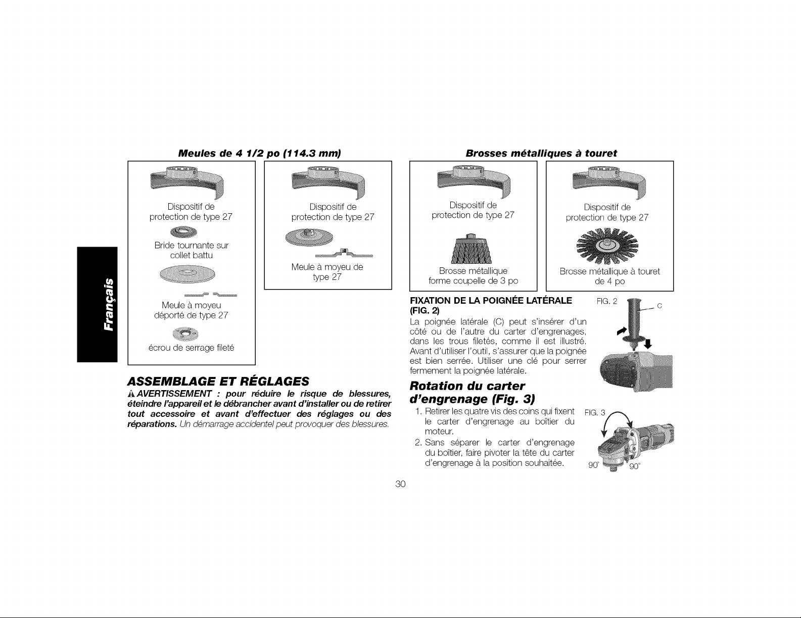
Meules de 4 1/2 po (114.3 mm)
Brosses m_tallii
ues _ touret
Dispositif de
protection de type 27
Bride tournante sur
collet battu
Meule a,moyeu
deporte de type 27
ecrou de serrage filete
Dispositif de
protection de type 27
Meule a,moyeu de
type 27
ASSEMBLAGE ET REGLAGES
_AVERTISSEMENT : pour r_duire le risque de blessures,
_teindre I'appareil et le d_brancher avant d'installer ou de retirer
tout accessoire et avant d'effectuer des r_glages ou des
r_parations. Un demarrage accidentel peut provoquer des blessures,
Dispositif de
protection de type 27
Brosse metallique
forme coupelle de 3 po
FIXATION DE LA POIGN#E LATERALE
(FIG. 2)
La poignee laterale (C) peut s'inserer d'un
c6te ou de I'autre du carter d'engrenages,
dans les trous filetes, comme il est illustre.
Avant d'utiliser I'outil, s'assurer que la poignee
est bien serree. Utiliser une cle pour serrer
fermement la poignee laterale.
Rotation du carter
d'engrenage (Fig. 3)
1. Retirer les quatre vis des coins qui fixent
le carter d'engrenage au boTtier du
moteur.
2. Sans separer le carter d'engrenage
du boTtier,faire pivoter la t_te du carter
d'engrenage a,la position souhaitee.
3O
Dispositif de
protection de type 27
Brosse metallique a,touret
de 4 po
FIG. 2
FIG. 3
90' 90°
C
Page 32
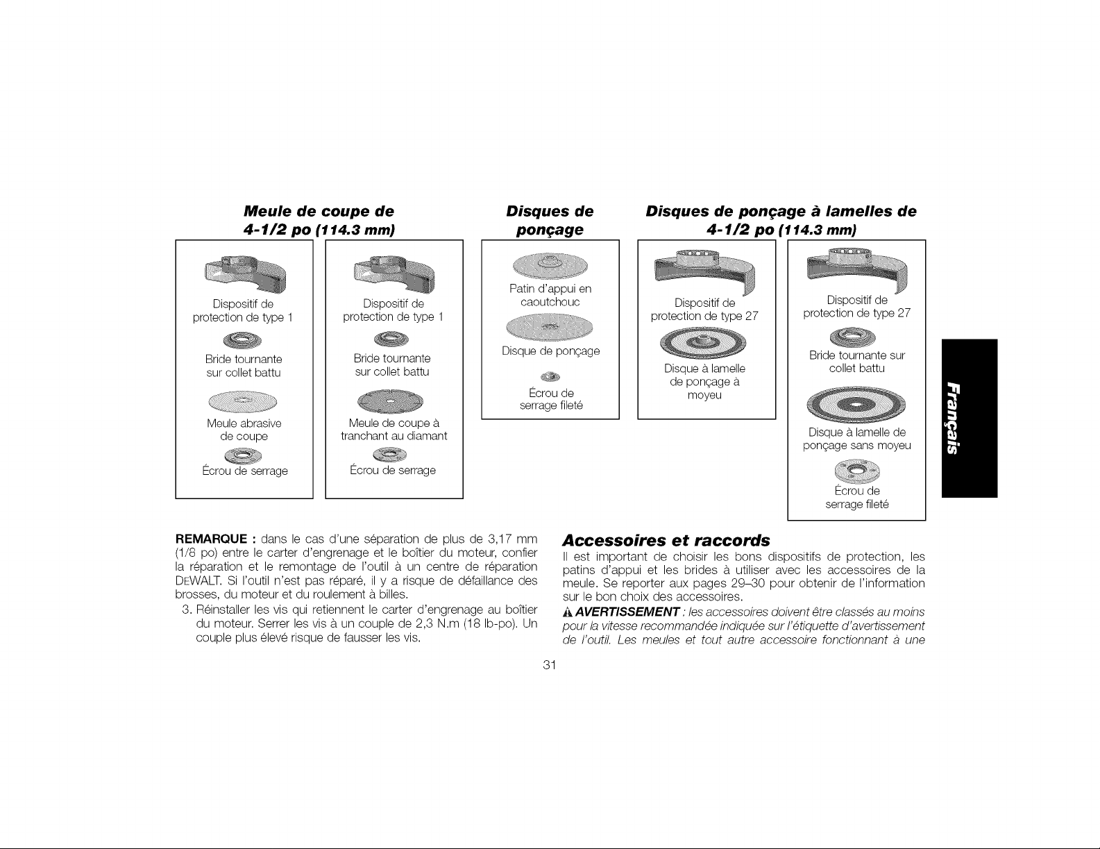
Meule de coupe de
4-1/2 po
114.3 mm)
Disques de
pone;age
Disques de pon
4-1/2 po
:age _ lamelles de
r114.3 mm)
Patin d'appui en
Dispositifde
protection de type 1
Bridetournante
sur collet battu
Meule abrasive
de coupe
Ecroude serrage
Dispositif de
protection de type 1
Bride tournante
sur collet battu
Meule de coupe _,
tranchant au diamant
Ecrou de serrage
caoutchouc
Disque de pongage
serrage filete
REMARQUE :dans le cas d'une separation de plus de 3,17 mm
(1/8 po) entre le carter d'engrenage et le boTtier du moteur, confier
la reparation et le remontage de routil a, un centre de reparation
DEWALT. Si routil n'est pas repare, il y a risque de defaillance des
brosses, du moteur et du roulement a,billes.
3. Reinstaller les vis qui retiennent le carter d'engrenage au boTtier
du moteur. Serrer les vis a,un couple de 2,3 N.m (18 Ib-po). Un
couple plus elev6 risque de fausser les vis.
Dispositif de
protection de type 27
Bride tournante sur
collet battu
Disque b, lamelle de
pongage sans moyeu
Ecrou de
Dispositifde
protection de type27
Disque b, lamelle
de pongage b,
moyeu
Ecrou de
serrage filete
Accessoires et raccords
II est important de choisir les bons dispositifs de protection, les
patins d'appui et les brides a, utiliser avec les accessoires de la
meule. Se reporter aux pages 29-30 pour obtenir de I'information
sur le bon choix des accessoires.
A AVERTISSEMENT: les accessoires doivent _tre classes au moins
pour la vitesse recommandee indiquee sur I'etiquette d'avertissement
de I'outil, Les meules et tout autre accessoire fonctionnant a une
31
Page 33
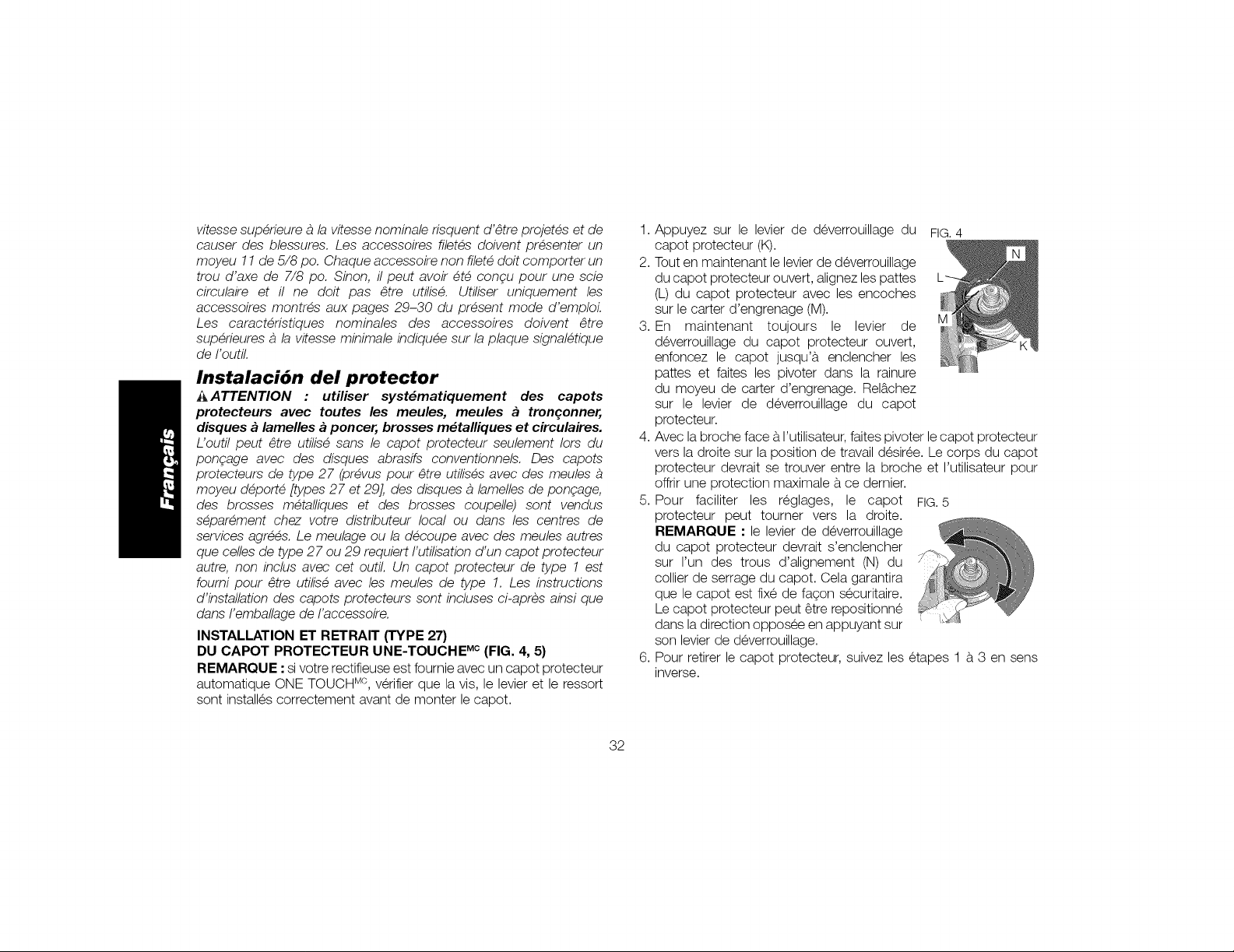
vitesse superieure a la vitesse nominale risquent d'etre projetes et de
causer des blessures. Les accessoires filetes doivent presenter un
moyeu 11 de 5/8 po. Chaque accessoire non filete doit comporter un
trou d'axe de 7/8 po. Sinon, il peut avoir ete conqu pour une scie
circulaire et il ne doit pas _tre utilise. Utiliser uniquement les
accessoires montres aux pages 29-30 du present mode d'emploL
Les caracteristiques nominales des accessoires doivent _tre
superieures a la vitesse minimale indiquee sur la plaque signaletique
de I'outil.
Instalaci6n del protector
_ATTENTION : utiliser syst_matiquement des capots
protecteurs avec toutes /es meules, meules a tronqonner,
disques a lamelles a poncer, brosses m_talliques et circulaires.
L'outil peut _tre utilise sans le capot protecteur seulement lots du
pongage avec des disques abrasifs conventionnels. Des capots
protecteurs de type 27 (prevus pour _tre utilises avec des meules
moyeu deporte [types 27 et 29], des disques a lamelles de ponqage,
des brosses metalliques et des brosses coupelle) sont vendus
separement chez votre distributeur local ou dans les centres de
services agrees. Le meulage ou la decoupe avec des meules autres
que celles de type 27 ou 29 requiert I'utilisation d'un capot protecteur
autre, non inclus avec cet outil. Un capot protecteur de type 1 est
foumi pour _tre utilise avec les meules de type 1. Les instructions
d'installation des capots protecteurs sont incluses ci-apres ainsi que
dans I'emballage de I'accessoire.
INSTALLATION ET RETRAIT (TYPE 27)
DU CAPOT PROTECTEUR UNE-TOUCHE ic (FIG. 4, 5)
REMARQUE : si votre rectifieuse est fournie avec un capot protecteur
automatique ONE TOUCH Mc,verifier que la vis, le levier et le ressort
sont installes correctement avant de monter le capot.
1,
Appuyez sur le levier de deverrouillage du FIG.4
capot protecteur (K).
2.
Tout en maintenant le levier de deverrouillage
du capot protecteur ouvert, alignez les pattes
(L) du capot protecteur avec les encoches
sur le carter d'engrenage (M).
3,
En maintenant toujours le levier de
deverrouillage du capot protecteur ouvert,
enfoncez le capot jusqu'a, enclencher les
pattes et faites les pivoter dans la rainure
du moyeu de carter d'engrenage. Rel_.chez
sur le levier de deverrouillage du capot
protecteur.
4,
Avec la broche face a.I'utilisateur, faites pivoter lecapot protecteur
vers la droite sur la position de travail desiree. Le corps du capot
protecteur devrait se trouver entre la broche et I'utilisateur pour
offrir une protection maximale a.ce dernier.
5,
Pour faciliter les reglages, le capot FIG.5
protecteur peut tourner vers la droite.
REMARQUE "le levier de deverrouillage
du capot protecteur devrait s'enclencher
sur run des trous d'alignement (N) du
collier de serrage du capot. Cela garantira
que le capot est fixe de fagon securitaire.
Le capot protecteur peut _tre repositionne
dans la direction opposee en appuyant sur
son levier de deverrouillage.
6,
Pour retirer le capot protecteur, suivez les etapes 1 a.3 en sens
inverse.
32
Page 34
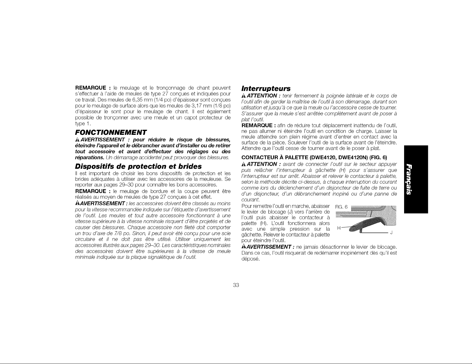
REMARQUE : le meulage et le trongonnage de chant peuvent
s'effectuer a. raide de meules de type 27 congues et indiquees pour
ce travail. Des meules de 6,35 mm (1/4 po) d'epaisseur sont congues
pour le meulage de surface alors que les meules de 3,17 mm (1/8 po)
d'epaisseur le sont pour le meulage de chant. II est egalement
possible de trongonner avec une meule et un capot protecteur de
type 1.
FONCTIONNEMENT
_AVERTISSEMENT : pour r_duire le risque de blessures,
_teindre I'appareil et le d_brancher avant d'installer ou de retirer
tout accessoire et avant d'effectuer des r_glages ou des
r_parations. Un demarrage accidentel peut provoquer des blessures.
Dispositifs de protection et brides
II est important de choisir les bons dispositifs de protection et les
brides adequates & utiliser avec les accessoires de la meuleuse. Se
reporter aux pages 29-30 pour connaTtreles bons accessoires.
REMARQUE : le meulage de bordure et la coupe peuvent _tre
realises au moyen de meules de type 27 congues a.cet effet.
E_,AVERTISSEMENT : les accessoires doivent _tre classes au moins
pour la vitesse recommandee indiquee sur I'etiquette d'avertissement
de I'outil. Les meules et tout autre accessoire fonctionnant a une
vitesse superieure a la vitesse nominale risquent d'etre projetes et de
causer des blessures. Chaque accessoire non filete doit comporter
un trou d'axe de 7/8 po. Sinon, il peut avoir ete conqu pour une scie
circulaire et il ne doit pas _tre utilis& Utiliser uniquement les
accessoires illustres aux pages 29-30. Les caracteristiques nominales
des accessoires doivent _tre superieures a la vitesse de meule
minimale indiquee sur la plaque signaletique de I'outil.
Interrupteurs
A ATTENTION : tenir fermement la poignee laterale et le corps de
I'outil afin de garder la ma_trisede I'outil a son demarrage, durant son
utilisation et jusqu'a ce que la meule ou I'accessoire cesse de toumer.
S'assurer que la meule s'est arr_tee completement avant de poser
plat I'outil.
REMARQUE : afin de reduire tout deplacement inattendu de routil,
ne pas allumer ni eteindre routil en condition de charge. Laisser la
meule atteindre son plein regime avant d'entrer en contact avec la
surface de la piece. Soulever I'outil de la surface avant de reteindre.
Attendre que I'outil cesse de tourner avant de le poser & plat.
CONTACTEUR .APALE'I-I'E (DWE4120, DWE4120N) (FIG. 6}
AATTENTION : avant de connecter I'outil sur le secteur appuyer
puis rel4cher I'interrupteur a g4chette (H) pour s'assurer que
I'interrupteur est sur arr_t. Abaisser et relever le contacteur a palette,
selon la methode decrite ci-dessus, a chaque interruption du courant
comme lots du declenchement d'un disjoncteur de fuite de terre ou
d'un disjoncteur, d'un debranchement inopine ou d'une panne de
courant.
Pour remettre routil en marche, abaisser FIG.6
le levier de blocage (J) vers rarriere de
routil puis abaisser le contacteur a.
palette (H). L'outil fonctionnera alors
avec une simple pression sur la
gb.chette. Relever lecontacteur & palette J
pour eteindre routil.
_AVERTISSEMENT: ne jamais desactionner le levier de blocage.
Dans ce cas, routil risquerait de redemarrer inopinement des qu'il est
depose.
33
Page 35
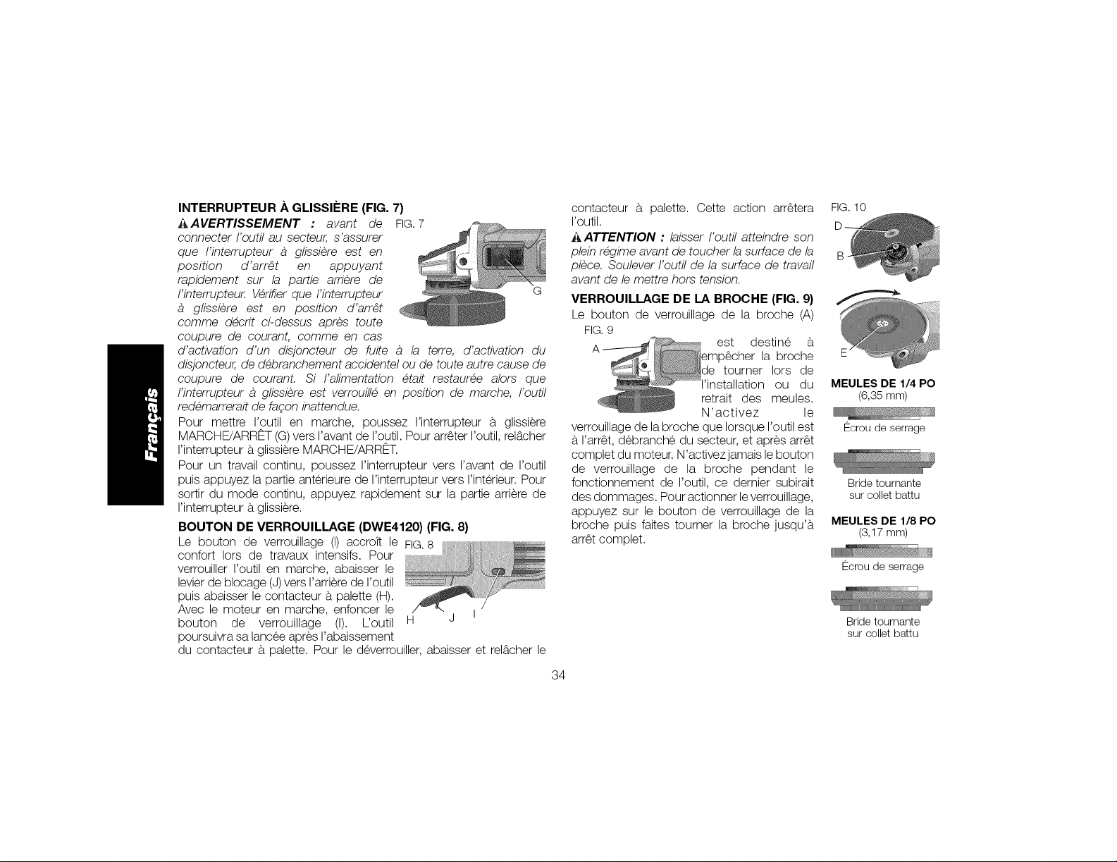
INTERRUPTEUR ._,GLISSIF:RE (FIG. 7)
_AVERTISSEMENT : avant de FIG.7
connecter I'outil au secteur, s'assurer
que I'interrupteur a glissiere est en
position d'arr_t en appuyant
rapidement sur la partie arriere de
I'interrupteur. Verifierque I'interrupteur G
glissiere est en position d'arr_t
comme decrit ci-dessus apres toute
coupure de courant, comme en cas
d'activation d'un disjoncteur de fuite a la terre, d'activation du
disjoncteur, de debranchement accidentel ou de toute autre cause de
coupure de courant. Si I'alimentation etait restauree alors que
I'interrupteur a glissiere est verrouille en position de marche, I'outil
redemarrerait de fagon inattendue.
Pour mettre I'outil en marche, poussez I'interrupteur a, glissiere
MARCHE/ARRF:T (G)vers ravant de routil. Pour arr_ter I'outil, rel_,cher
rinterrupteur a,glissiere MARCHE/ARRET.
Pour un travail continu, poussez rinterrupteur vers ravant de routil
puis appuyez la partie anterieure de I'interrupteur vers rinterieur. Pour
sortir du mode continu, appuyez rapidement sur la partie arriere de
rinterrupteur a,glissiere.
BOUTON DE VERROUlLLAGE (DWE4120) (FIG. 8)
Le bouton de verrouillage (I) accroTt le FIG.8
confort Iors de travaux intensifs. Pour
verrouiller routil en marche, abaisser le
levier de blocage (J)vers rarriere de I'outil
puis abaisser le contacteur a,palette (H).
Avec le moteur en marche, enfoncer le I
bouton de verrouillage (I). L'outil H J
poursuivra sa lancee apres rabaissement
du contacteur a, palette. Pour le deverrouiller, abaisser et rel_,cher le
contacteur a, palette. Cette action arr_tera
routil.
_ ATTENTION : laisser I'outil atteindre son
plein regime avant de toucher la surface de la
piece. Soulever I'outil de la surface de travail
avant de le mettre hors tension.
VERROUILLAGE DE LA BROCHE (FIG. 9)
Le bouton de verrouillage de la broche (A)
FIG.9
verrouillage de la broche que Iorsque routil est
a,rarr_t, debranche du secteur, et apres arr_t
complet du moteur. N'activezjamais le bouton
de verrouillage de la broche pendant le
fonctionnement de routil, ce dernier subirait
des dommages. Pour actionner le verrouillage,
appuyez sur le bouton de verrouillage de la
broche puis faites tourner la broche jusqu'a,
arr_t complet.
34
FIG. 10
E /
MEULES DE 1/4 PO
(6,35mm)
Ecrou deserrage
Bride tournante
sur collet battu
MEULES DE 1/8 PO
(3,17 mm)
Ecrou de serrage
Bride tournante
sur collet battu
Page 36

Montage et utilisation de meules
moyeu d_port_ et de disques _ lamelles
de pon_;age
MONTAGE ET DI_MONTAGE DE MEULES ,_,MOYEU (FIG. 10)
Les meules a,moyeu sont posees directement sur la broche filetee
11 de 5/8 po. Le filetage de I'accessoire doit correspondre au
filetage de la broche.
1. ©tez la bride tournante (D) en la tirant hors de I'outil.
2. Enfiler la roue sur le fuseau a,la main.
3. Enfoncer le bouton de verrouillage de la broche (B), puis serrer le
moyeu de la meule avec la cle.
4. Inverser I'ordre de la procedure susmentionnee pour deposer la
meule.
AVIS : negliger de bien enfoncer la meule avant d'allumer I'outil risque
d'endommager I'outil ou la meule,
MONTAGE DE MEULES SANS MOYEU (FIG. 10}
Les meules a,moyeu deporte de type 27 doivent _tre utilisees avec
les brides incluses. Reportez-vous a, la section Accesseires et
raccords pour plus d'informations.
1. Poser la bride tournante sur collet battu non filetee (D) sur la
broche (B), la section surelevee (pilote) se trouvant contre la
meule. S'assurer que I'enfoncement de la bride tournante sur
collet battu repose sur les meplats de la broche avant de mettre la
meule. Retirer de la machine la bride tournante sur collet battu en
imprimant un mouvement de traction et de torsion
2. Mettre la meule contre la bride tournante sur collet battu de
maniere a,centrer la meule sur la section surelevee (pilote) de la
bride.
3. Au moment d'enfoncer le bouton deverrouillage de la broche,
visser I'ecrou de serrage (E) sur la broche. Si la meule posee
depasse de 3,17 mm (1/8 po) d'epaisseur, mettre I'ecrou de
serrage filete sur la broche de maniere a, ce que la section
surelevee (pilote) s'insere au centre de la meule. Si la meule posee
correspond a, une epaisseur de 3,17 mm (1/8 po) ou moins,
mettre I'ecrou de serrage filete sur la broche de maniere a,ce que
la section surelevee (pilote) ne se trouve pas contre la meule.
4. Au moment d'enfoncer le bouton de verrouillage de la broche,
visser I'ecrou de serrage au moyen d'une cle.
5. Pour deposer la meule, enfoncer le bouton de verrouillage de la
broche, puis desserrer I'ecrou de serrage filete au moyen d'une
cle.
REMARQUE •si la meule tourne apres avoir serre I'ecrou de serrage,
verifier le sens de I'ecrou de serrage filete. Si une meule mince est
posee et que le pilote de I'ecrou de serrage se trouve contre la meule,
cette derniere tournera parce que la hauteur du pilote emp_che
I'ecrou de serrage de tenir la meule.
MEULAGE DE FINITION AVEC DES MEULES (FIG. 11)
1, Laisser I'outil atteindre son plein
regime avant qu'il n'entre en contact
avec la surface de la piece.
2. Appliquer une pression minimum a, la
surface de la piece, ce qui permet a,
I'outil de fonctionner a,vitesse elev6e. La
vitesse de meulage est superieure Iorsque I'outil fonctionne a,une
vitesse elev6e.
3. Maintenir un angle de 20° a, 30° entre I'outil et la surface de la
piece.
35
Page 37

4.DeplacerconstammentI'outilversI'avantetI'arrierepoureviter
decreerdesenfoncementsdanslasurfacedelapiece.
5.RetirerI'outildelasurfacedelapieceavantdeI'eteindre.Attendre
queI'outilcessedetourneravantdeleposera,plat.
MEULAGE DE BORDURE AVEC DES MEULES (FIG. 12)
_AVERTISSEMENT : les meules utilisees pour la coupe et le
meulage de bordure peuvent se briser si elles se plient ou se tordent
durant I'utilisation de I'outil, pour un travail de trongonnage ou de
meulage profond, Afin de reduire le risque de blessure grave,
restreindre I'utilisation de ces meules avec un dispositif de protection
de type 27, ce qui assure une coupe et un entaillage peu profond
(moins de 1/2 po de profondeur), Le c6te ouvert du dispositif de
protection doit _tre place de maniere a _tre loin de I'operateur, Pour
obtenir une coupe profonde au moyen d'une meule trongonneuse de
type 1, utiliser un dispositif de protection ferme de type 1.Se reporter
au tableau figurant aux pages 29-30 pour en savoir plus, Les
dispositifs de protection de type 1 sont offerts, moyennant un
supplement, aupres d'un concessionnaire ou d'un centre de
reparation autorise de votre region,
1. Laisser I'outil atteindre son plein regime
avant qu'il n'entre en contact avec la
surface de la piece.
2. Appliquer une pression minimum a, la
surface de la piece, ce qui permet
a, I'outil de fonctionner a, une vitesse
elev6e. La vitesse de meulage est
superieure Iorsque I'outil fonctionne a,
une vitesse elev6e.
3. Se placer de maniere a,ce que le dessous ouvert de la meule soit
eloign6 de vous.
4. Lorsqu'une coupe est engagee et qu'une encoche est realisee
dans la piece, ne pas modifier I'angle de coupe. Le fait de
modifier I'angle risque de faire plier la meule, ce qui peut la briser.
Les meules de bordure ne sont pas congues pour resister aux
pressions laterales causees par la flexion.
5. Retirer I'outil de la surface de la piece avant de I'eteindre. Attendre
que I'outil cesse de tourner avant de le poser a,plat.
_AVERTISSEMENT : ne pas utiliser de meules de bordure/de
coupe pour les applications de meulage de finition, car ces meules ne
sont pas congues pour resister aux pressions laterales presentes
dans le meulage de finition, IIpeut en resulter un bris de meule et des
blessures,
FINITION DE SURFACE AVEC DES DISQUES ._ LAMELLES DE
PONqAGE (FIG. 13)
f, Laisser I'outil atteindre son plein regime avant qu'il n'entre en
contact avec la surface de la piece,
2, Appliquer une pression minimum a,
la surface de la piece, ce qui permet
a,I'outil de fonctionner a,une vitesse
elev6e. La vitesse de pongage est
superieure Iorsque I'outil fonctionne a,
une vitesse elev6e.
3. Maintenir un angle de 5°a, 10°entre I'outil et la surface de lapiece.
4. Deplacer constamment I'outil vers I'avant et I'arriere pour eviter
de creer des enfoncements dans la surface de la piece.
5. Retirer I'outil de la surface de la piece avant de I'eteindre. Attendre
que I'outil cesse de tourner avant de le poser a,plat.
I
36
Page 38

MONTAGE DES PATINS D'APPUI ET DE PONQAGE (FIG. 14)
_AVERTISSEMENT : il faut poser de nouveau le bon dispositif de
protection pour les applications de meule, de disque a lamelle de
ponqage, de brosse metallique ou de brosse metallique a touret
apres les applications de ponqage,
1. Mettre ou visser adequatement le patin d'appui (O) sur la
broche.
2. Poser le disque de pongage (P) sur le patin d'appui.
3. Au moment d'enfoncer le dispositif FIG.14 P
de verrouillage de la broche, visser
I'ecrou de serrage (E) sur la broche
et guider le moyeu sureleve de
I'ecrou de serrage au centre du
disque de pongage et du patin ........................
d'appui.
4. Serrer manuellement I'ecrou de
serrage. Enfoncer ensuite le bouton
de verrouillage de la broche tout en
tournant le disque de pongage de
maniere a,ce que le disque et I'ecrou
soient ajustes serres.
5. Pour enlever la meule, saisir et tourner le patin d'appui et le
patin de pongage tout en enfongant le bouton de verrouillage
de la broche.
UTILISATION DES PATINS DE PONQAGE ET D'APPUl
(FIG. 15)
Choisir le papier abrasif convenant a,I'application. Le papier abrasif
est offert en differentes tailles de grains. Les grains grossiers
assurent un taux d'enlevement de la matiere superieur et un fini
brut. Les grains plus fins procurent un taux d'enlevement de matiere
inferieur et un fini plus lisse.
Commencer avec des disques a,grains grossiers pour un enlevement
rapide de matiere rugueuse. Changer pour un papier a, grains
moyens, puis terminer avec un disque a,grains fins pour obtenir une
finition optimale.
Grain grossier 16-30
Grain moyen 36-80
Grain de finition 100-120
Grain tres fin 150-180
1. Laisser I'outil atteindre son plein regime avant qu'il n'entre en
contact avec la surface de la piece.
2. Appliquer une pression minimum a,la
surface de la piece, ce qui permet a,
I'outil de fonctionner a, une vitesse
elev6e. La vitesse de pongage est
superieure Iorsque I'outil fonctionne a,
une vitesse elev6e.
3. Maintenir un angle de 5°a,15°entre I'outil et la surface de la piece.
Le disque de pongage doit entrer en contact avec environ 1 po
de surface de la piece.
4. Deplacer constamment I'outil en ligne droite pour eviter de br01er
la surface de la piece et d'y faire des marques de cercle. Si I'outil
repose sur la surface de la piece sans se deplacer ou si I'outil
imprime un mouvement circulaire, cela risque de causer des
br01ureset des marques de cercle sur la surface de la piece.
5. Retirer I'outil de la surface de la piece avant de I'eteindre. Attendre
que I'outil cesse de tourner avant de le poser a,plat.
37
Page 39
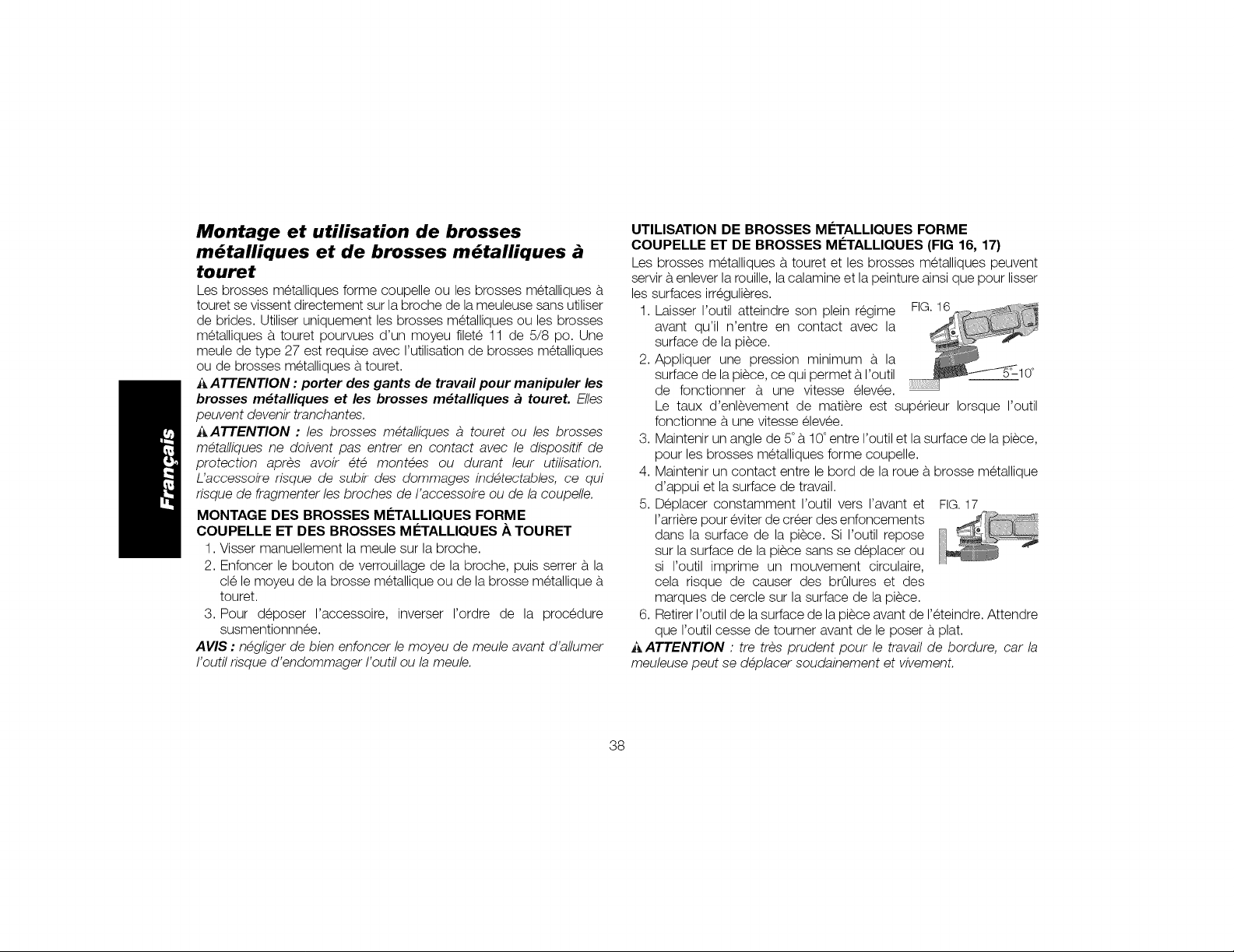
Montage et utilisation de brosses
m_talliques et de brosses m_talliques
touret
Les brosses metalliques forme coupelle ou les brosses metalliques &
touret se vissent directement sur la broche de la meuleuse sans utiliser
de brides. Utiliser uniquement les brosses metalliques ou les brosses
metalliques a, touret pourvues d'un moyeu filete 11 de 5/8 po. Une
meule de type 27 est requise avec rutilisation de brosses metalliques
ou de brosses metalliques &touret.
_ ATTENTION : porter des gants de travail pour manipuler les
brosses m_talliques et les brosses m_talliques a toureL E/les
peuvent devenir tranchantes,
_ATTENTION : les brosses metalliques a touret ou les brosses
metalliques ne doivent pas entrer en contact avec le dispositif de
protection apres avoir ete montees ou durant leur utilisation,
L'accessoile risque de subir des dommages indetectables, ce qui
risque de fragmenter les broches de I'accessoire ou de la coupelle,
MONTAGE DES BROSSES M#TALLIQUES FORME
COUPELLE ET DES BROSSES M#TALLIQUES .&,TOURET
1. Visser manuellement la meule sur la broche.
2. Enfoncer le bouton de verrouillage de la broche, puis serrer a,la
cle le moyeu de la brosse metallique ou de la brosse metallique &
touret.
3. Pour deposer I'accessoire, inverser rordre de la procedure
susmentionnnee.
AVIS : negliger de bien enfoncer le moyeu de meule avant d'allumer
I'outil risque d'endommager I'outil ou la meule,
UTILISATION DE BROSSES M#TALLIQUES FORME
COUPELLE ET DE BROSSES M#TALLIQUES (FIG 16, 17)
Les brosses metalliques a,touret et les brosses metalliques peuvent
servir a,enlever la rouille, lacalamine et la peinture ainsi que pour lisser
les surfaces irregulieres.
1. Laisser I'outil atteindre son plein regime FIG.16
avant qu'il n'entre en contact avec la
surface de la piece.
2. Appliquer une pression minimum a, la
surface de la piece, ce qui permet & I'outil
de fonctionner & une vitesse elev6e.
Le taux d'enlevement de matiere est superieur Iorsque routil
fonctionne a, une vitesse elev6e.
3. Maintenir un angle de 5°b, 10°entre I'outil et la surface de lapiece,
pour les brosses metalliques forme coupelle.
4. Maintenir un contact entre le bord de la roue & brosse metallique
d'appui et la surface de travail.
5. Deplacer constamment I'outil vers ravant et FIG.17
rarriere pour eviter de creer des enfoncements
dans la surface de la piece. Si I'outil repose
sur la surface de la piece sans se deplacer ou
si routil imprime un mouvement circulaire,
cela risque de causer des brQlures et des
marques de cercle sur la surface de la piece.
6. Retirer I'outil de la surface de la piece avant de reteindre. Attendre
que routil cesse de tourner avant de le poser a,plat.
i_,ATTENTION : tre tres prudent pour le travail de bordure, car la
meuleuse peut se deplacer soudainement et vivement,
38
Page 40
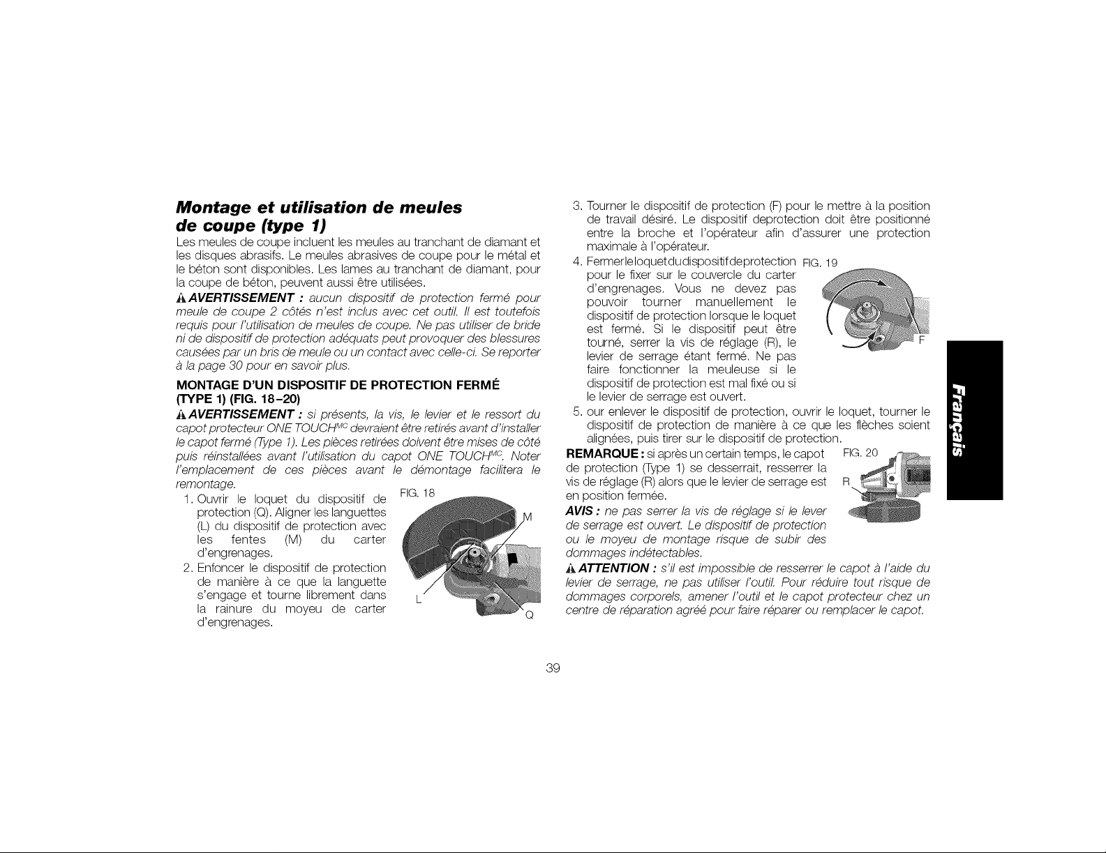
Montage et utilisation de meules
de coupe (type 1)
Les meules de coupe incluent les meules au tranchant de diamant et
les disques abrasifs. Le meules abrasives de coupe pour le metal et
le beton sont disponibles. Les lames au tranchant de diamant, pour
la coupe de beton, peuvent aussi _tre utilisees.
i_AVERTISSEMENT : aucun dispositif de protection ferme pour
meule de coupe 2 c6tes n'est inclus avec cet outil. II est toutefois
requis pour I'utilisation de meules de coupe. Ne pas utiliser de bride
ni de dispositif de protection adequats peut provoquer des blessures
causees par un bris de meule ou un contact avec celle-cL Se reporter
la page 30 pour en savoir plus.
MONTAGE D'UN DISPOSITIF DE PROTECTION FERM#
(TYPE 1) (FIG. 18-20)
_,AVERTISSEMENT : si presents, la vis, le levier et le ressort du
capot protecteur ONE TOUCHMcdevraient _tre retires avant d'installer
le capot ferme (Type 1). Les pieces retirees doivent _tre mises de c6te
puis reinstallees avant I'utilisation du capot ONE TOUCH Mc. Noter
I'emplacement de ces pieces avant le demontage facilitera le
remontage.
1. Ouvrir le Ioquet du dispositif de FIG.18
protection (Q).Aligner les languettes
(L) du dispositif de protection avec
les fentes (M) du carter
d'engrenages.
2. Enfoncer le dispositif de protection
de maniere a. ce que la languette
s'engage et tourne librement dans L
la rainure du moyeu de carter
d'engrenages.
Q
3,
Tourner le dispositif de protection (F) pour le mettre a.la position
de travail desire. Le dispositif deprotection doit _tre positionne
entre la broche et I'operateur afin d'assurer une protection
maximale a. roperateur.
4. Fermerleloquetdudispositifdeprotection FIG.19
pour le fixer sur le couvercle du carter
d'engrenages. Vous ne devez pas
pouvoir tourner manuellement le
dispositif de protection Iorsque le Ioquet
est ferme. Si le dispositif peut _tre
tourne, serrer la vis de reglage (R), le F
levier de serrage etant ferme. Ne pas
faire fonctionner la meuleuse si le
dispositif de protection est mal fixe ou si
le levier de serrage est ouvert.
5. our enlever le dispositif de protection, ouvrir le Ioquet, tourner le
dispositif de protection de maniere a. ce que les fleches soient
alignees, puis tirer sur le dispositif de protection.
REMARQUE : si apres un certain temps, le capot FIG.20
de protection (Type 1) se desserrait, resserrer la
vis de reglage (R)alors que le levierde serrage est R
en position fermee.
AVIS : ne pas serrer la vis de reglage si le lever
de serrage est ouvert. Le dispositif de protection
ou le moyeu de montage risque de subir des
dommages indetectables.
ATTENTION : s'il est impossible de resserrer le capot a I'aide du
levier de serrage, ne pas utiliser I'outil. Pour reduire tout risque de
dommages corporels, amener I'outil et le capot protecteur chez un
centre de reparation agree pour faire reparer ou remplacer le capot.
39
Page 41
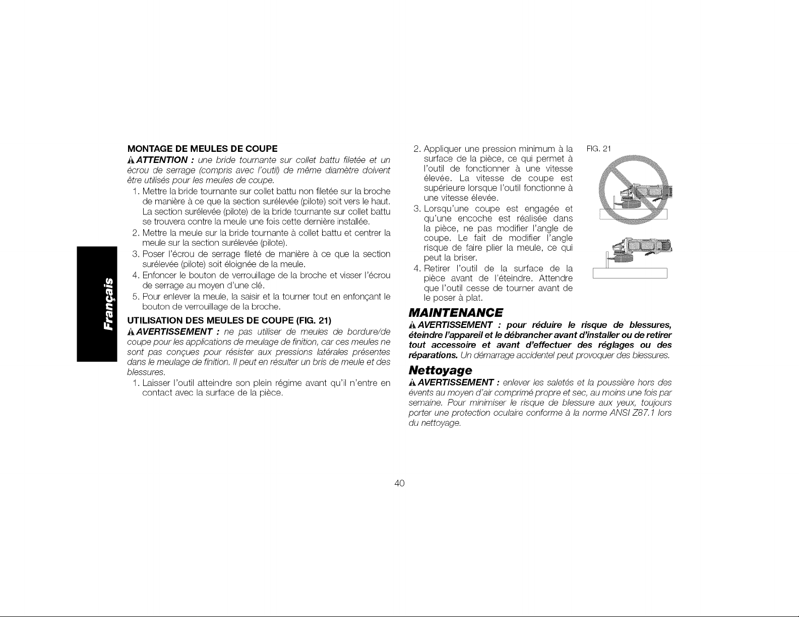
MONTAGE DE MEULES DE COUPE
i_,ATTENTION : une bride toumante sur collet battu filetee et un
ecrou de serrage (compris avec I'outil) de m_me diametre doivent
_tre utilises pour les meules de coupe,
1. Mettre la bride tournante sur collet battu non filetee sur la broche
de maniere a,ce que la section surelevee (pilote) soit vers le haut.
La section surelevee (pilote) de la bride tournante sur collet battu
se trouvera contre la meule une fois cette derniere installee.
2. Mettre la meule sur la bride tournante a,collet battu et centrer la
meule sur la section surelevee (pilote).
3. Poser I'ecrou de serrage filete de maniere a,ce que la section
surelevee (pilote) soit eloign6e de la meule.
4. Enfoncer le bouton de verrouillage de la broche et visser I'ecrou
de serrage au moyen d'une cle.
5. Pour enlever la meule, la saisir et la tourner tout en enfongant le
bouton de verrouillage de la broche.
UTILISATION DES MEULES DE COUPE (FIG. 21)
_AVERTISSEMENT : ne pas utiliser de meules de bordure/de
coupe pour les applications de meulage de finition, car ces meules ne
sont pas congues pour resister aux pressions laterales presentes
dans le meulage de finition, IIpeut en resulter un bris de meule et des
blessures,
1. Laisser routil atteindre son plein regime avant qu'il n'entre en
contact avec la surface de la piece.
2. Appliquer une pression minimum a,la FIG.21
surface de la piece, ce qui permet a,
I'outil de fonctionner a, une vitesse
elev6e. La vitesse de coupe est
superieure Iorsque I'outil fonctionne a,
une vitesse elev6e.
3. Lorsqu'une coupe est engagee et
qu'une encoche est realisee dans
la piece, ne pas modifier I'angle de
coupe. Le fait de modifier I'angle
risque de faire plier la meule, ce qui
peut la briser.
4. Retirer I'outil de la surface de la
piece avant de I'eteindre. Attendre
que I'outil cesse de tourner avant de
le poser a, plat.
MAINTENANCE
i_AVERTISSEMENT : pour r_duire le risque de blessures,
_teindre I'appareil et le d_brancher avant d'installer ou de retirer
tout accessoire et avant d'effectuer des r_glages ou des
r_parations. Un demarrage accidentel peut provoquer des blessures,
Nettoyage
AAVERTISSEMENT : enlever les saletes et la poussiere hors des
events au moyen d'air comprime propre et sec, au moins une lois par
semaine, Pour minimiser le risque de blessure aux yeux, toujours
porter une protection oculaire conforme a la norme ANSI Z87,1 lots
du nettoyage,
4O
Page 42

i_,AVERTISSEMENT : ne jamais utiliser de solvants ni d'autres
produits chimiques puissants pour nettoyer les pieces non metalliques
de I'outil. Ces produits chimiques peuvent affaiblir les materiaux de
plastique utilises dans ces pieces. Utiliser un chiffon humecte
uniquement d'eau et de savon doux. Ne jamais laisser de liquide
penetrer dans I'outil et n'immerger aucune pattie de I'outil dans un
liquide.
Accessoires
i_AVERTISSEMENT : puisque les accessoires autres que ceux
offerts par DEWALT n'ont pas ete testes avec ce produit, leur
utilisation pourrait s'averer dangereuse. Pour reduire le risque de
blessures, utiliser exclusivement les accessoires DEWALT
recommandes avec le present produit.
Les accessoires recommandes pour cet outil sont vendus separement
au centre de service de votre region. Pour obtenir de I'aide concernant
I'achat d'un accessoire, communiquer avec DEWALT Industrial Tool
Co., 701 East Joppa Road, Baltimore, MD 21286 aux Etats-Unis;
composer le 1 800 433-9258 (1 800 4-DEWALT) ou visiter notre site
Web : www.dewalt.com.
Rdparations
Pour assurer la S¢:CURITEet la FIABILIT¢:du produit, les reparations,
I'entretien et les reglages doivent _tre realises (cela comprend
I'inspection et le remplacement du balai) par un centre de reparation
en usine DEWALT, un centre de reparation agree DEWALT ou
par d'autres techniciens qualifies. Toujours utiliser des pieces de
rechange identiques.
Registre en ligne
Merci pour votre achat. Enregistrez des maintenant votre produi :
• RI_PARATIONS SOUS GARANTIE : cette carte remplie vous
permettra de vous prevaloir du service de reparations sous
garantie de fagon plus efficace dans le cas d'un probleme avec le
produit.
• CONFIRMATION DE PROPRII_TI_ :en cas de perte provoquee
par un incendie, une inondation ou un vol, cette preuve de
propriet6 vous servira de preuve aupres de votre compagnie
d'assurances.
• SI_CURITI_ : I'enregistrement de votre produit nous permettra
de communiquer avec vous dans I'eventualit6 peu probable de
I'envoi d'un avis de securit6 regi par la Ioi federale americaine de
la protection des consommateurs.
Registre en ligne a.www.dewalt.com/register.
Garantie limitee de trois ans
DEWALT reparera, sans frais, tout produit defectueux cause par un
defaut de materiel ou de fabrication pour une periode de trois ans a.
compter de la date d'achat. La presente garantie ne couvre pas les
pieces dont la defectuosite a et6 causee par une usure normale ou
I'usage abusif de I'outil. Pour obtenir de plus amples renseignements
sur les pieces ou les reparations couvertes par la presente garantie,
visiter le site www.dewalt.com ou composer le 1 800 433-9258 (1
800 4-DEWALT). Cette garantie ne s'applique pas aux accessoires
et ne vise pas les dommages causes par des reparations effectuees
par un tiers. Cette garantie confere des droits legaux particuliers a.
I'acheteur, mais celui-ci pourrait aussi beneficier d'autres droits variant
d'un etat ou d'une province a.I'autre.
41
Page 43
Enplusdelapresentegarantie,lesoutilsDEWALTsontcouvertspar
notre'
CONTRAT D'ENTRETIEN GRATUIT D'UN AN
DEWALTentretiendra I'outil et remplacera les pieces usees au cours
d'une utilisation normale et ce, gratuitement, pendant une periode
d'un an a,compter de la date d'achat.
GARANTIE DE REMBOURSEMENT DE 90 JOURS
Si I'acheteur n'est pas entierement satisfait, pour quelque raison que
ce soit, du rendement de I'outil electrique, du laser ou de la cloueuse
DF:WALT,celui-ci peut le retourner, accompagne d'un regu, dans les
90 jours a,compter de la date d'achat pour obtenir un remboursement
integral, sans aucun probleme.
AMI_RIQUE LATINE : cette garantie ne s'applique aux produits
vendus en Amerique latine. Pour ceux-ci, veuillez consulter les
informations relatives a, la garantie specifique presente dans
remballage, appeler rentreprise locale ou consulter le site Web pour
les informations relatives a,cette garantie.
REMPLACEMENT GRATUIT DES eTIQUETTES
D'AVERTISSEMENT : si les etiquettes d'avertissement deviennent
illisibles ou sont manquantes, composer le 1 800 433-9258 (1 800
4-DEWALT) pour en obtenir le remplacement gratuit.
.... °"°m @/
LESiO_S.SIEMP_LL_Ee_O_ECCZO_OCULar,SOlO
tniLIC_ A_CESOP,OOSCUYA_ELi_CIOA__OtaNAL SF_
eP_RACaONES_EPUL_O. LLEVES_t_p_E PROTECCIO_
DE OOMMAGES CO_PO_EL_, gUTIUSAT[Ug D(]IT tIRE Lg
N_Ua _ ff_IJLJS_JEU_, P_t_g
U1]U_EII_×CLUSNENENTDES_CC_SS01_S _0_ L_
yEr£SSENONJt_gLEESTEQ_IV_,LEmEO_SUp_I£UR_
_ C_LLEI_IaUE_ S_ L"0_TJt._TlUSEg
SyST_N_TlaU_MEt_T_E_C_TE_S AppRopRIENpO_N
.PBOTECTI[_N DE VOiES _ESPIP, ATOIRES a_Ea_S.
ELUSU_IO DE_
LE_ELMAt_UA_
_OUI_IS_UE
m /
42
Page 44

Definiciones: Normas de seguridad
Las siguientes definiciones describen el nivel de gravedad de
cada palabra de sepal. Lea el manual y preste atenciOn a estos
dmbolos.
_ PELIGFtO: indica una situacidn de peligro inminente que, si
no se evita, provocara la muerte o lesiones graves.
_ADVERTENCIA: indica una situacidn de peligro potencial
que, si no se evita, podria provocar la muerte o lesiones
graves.
A ATENClON: indica una situacidn de peligro potencial que, si
no se evita, posiblemente provocarfa lesiones leves o
moderadas.
AVlSO: se refiere a una practica no relacionada a lesiones
corporales que de no evitarse puede resu/tar en da_os a la
_propiedad.
SI TIENE ALGUNA DUDA O ALGON COMENTARIO SOBRE €:STA
U OTRA HERRAMIENTA DEWALT, LLAMENOS AL NOMERO
GRATUITO: 1-800-4-DEWALT (1-800-433-9258}.
_ DVERTENCIA: Para reducir el riesgo de /esiones, lea el
manual de instrucciones.
J
Advertencias generales de seguridad
para herramientas eldctricas
e instrucciones. El incumplimiento de las advertencias e
_ iADVERTENCIA! Lea todas las advertencias deseguridad
instrucciones puede provocar descargas electricas, incendios
o lesiones graves.
CONSERVE TODAS LAS ADVERTENCIAS
E INSTRUCCIONES PARA FUTURAS
CONSULTAS
El termino "herramienta electrica" incluido en las advertencias hace
referencia alas herramientas electricas operadas con corriente (con
cable electrico) o alas herramientas electricas operadas con baterfas
(inalambricas).
1) SEGURIDAD EN EL AREA DE TRABAJO
a) Mantenga el area de trabajo limpia y bien iluminada. Las
areas abarrotadas y oscuras propician accidentes.
b) No opere las herramientas el_ctricas en atmdsferas
explosivas, come ambientes donde haya polvo, gases
o liquidos inflamables. Las herramientas electricas originan
chispas que pueden encender el polvo o los vapores.
c) Mantenga alejados a los ni_os y a los espectadores
de la herramienta el_ctrica en funcionamiento. Las
distracciones pueden provocar la perdida de control
2} SEGURIDAD EL#CTRICA
a) Los enchufes de la herramienta el_ctrica deben
adaptarse al tomacorriente. Nunca modifique el
enchufe de ninguna manera. No utilice ningdn enchufe
adaptador con herramientas el_ctricas con conexidn a
tierra. Los enchufes no modificados y que se adaptan a los
tomacorrientes reduciran el riesgo de descarga electrica.
b) Evite el contacto corporal con superficies con descargas
a tierra como, per ejemplo, tuberias, radiadores, cocinas
el_ctricas y refrigeradores. Existe mayor riesgo de descarga
electrica si su cuerpo esta puesto a tierra.
c) No exponga las herramientas el_ctricas a la Iluvia o a
condiciones de humedad. Si entra agua a una herramienta
electrica, aumentara el riesgo de descarga electrica.
43
Page 45

d)No maltrate el cable. Nunca utilice el cable para
transportar, tirar o desenchufar la herramienta el_ctrica.
Mantenga el cable alejado del calor, el aceite, los
bordes filosos y las piezas moviles. Los cables dahados o
enredados aumentan el riesgo de descarga electrica.
e) AI operar una herramienta el_ctrica en el exterior, utilice
un cable prolongador adecuado para tal use. Ut///ce un
cable adecuado para uso en exteriores a finde reducir elriesgo
de descarga electrica.
Si el use de una herramienta el_ctrica en un lugar
hE/medo es imposible de evitar, utilice un suministro
protegido con un interrupter de circuffo per falla a tierra
(GFCI). El uso de un GFC/ reduce el riesgo de descargas
electricas.
3) SEGURIDAD PERSONAL
a) Permanezca alerta, controle Io que esta haciendo y
utilice el sentido comEm cuando emplee una herramienta
el_ctrica. No utilice una herramienta el_ctrica si
esta cansado o bajo el efecto de drogas, alcohol o
medicamentos. Un momento de descuido mientras se opera
una herramienta electrica puede provocar lesiones personales
graves.
b) Utilice equipos de proteccion personal. Siempre utilice
proteccion para los ojos. En las condiciones adecuadas, el
uso de equipos de proteccidn, como mascaras para polvo,
calzado de seguridad antideslizante, cascos o proteccidn
auditiva, reducira las lesiones personales.
c) Evite el encendido per accidente. AsegE/rese de que
el interrupter est_ en la posicion de apagado antes de
conectarlo a la fuente de energia o paquete de baterias,
o antes de levantar o transportar la herramienta.
Transportar herramientas electricas con el dedo apoyado en el
interruptor o enchufar herramientas electricas con el interruptor
en la posicidn de encendido puede propiciar accidentes.
d) Retire la clavija de ajuste o la Ilave de tuercas antes de
encender la herramienta el_ctrica. Una Ilave de tuercas
o una clavija de ajuste que quede conectada a una pieza
giratoria de la herramienta electrica puede provocar lesiones
personales.
e) No se estire. Conserve el equilibrio y parese
adecuadamente en todo memento. Esto permite un mejor
control de la herramienta electrica en situaciones inesperadas.
Use la vestimenta adecuada. No use ropas holgadas
ni joyas. Mantenga el cabello, la ropa y los guantes
alejados de las piezas en movimiento. Las ropas holgadas,
las joyas o el cabello largo pueden quedar atrapados en las
piezas en movimiento.
g) Si se suministran dispositivos para la conexidn de
accesorios con fines de recolecci6n y extracci6n de
polvo, aseg(/rese de que est_n conectados y que se
utilicen correctamente. El uso de dispositivos de reco/eccidn
de polvo puede reducir los peligros relacionados con el polvo.
4} USO Y MANTENIMIENTO DE LA HERRAMIENTA
ELleCTRICA
a) No fuerce la herramienta el_ctrica. Utilice la herramienta
el_ctrica correcta para el trabajo que realizara. Si se la
utiliza a la velocidad para la que rue disehada, la herramienta
electrica correcta permite trabajar mejor y de manera mas
segura.
b) No utilice la herramienta el_ctrica si no puede encenderla
o apagarla con el interrupter. Toda herramienta e/ectrica
que no pueda set controlada mediante el interruptor es
peligrosa y debe repararse.
44
Page 46

c) Desconecte el enchufe de la fuente de energia o el
paquete de baterias de la herramienta el_ctrica antes
de realizar ajustes, cambiar accesorios o almacenar
la herramienta el_ctrica. Estas medidas de seguridad
preventivas reducen el riesgo de encender la herramienta
electrica en forma accidental.
d) Guarde la herramienta el_ctrica que no est_ en uso fuera
del alcance de los nibos y no permita que otras personas
no familiarizadas con ella o con estas instrucciones
operen la herramienta. Las herramientas e/ectricas son
peligrosas si son operadas pot usuarios no capacitados.
e) Realice el mantenimiento de las herramientas
el_ctricas. Revise que no haya piezas en movimiento
mal alineadas o trabadas, piezas rotas o cualquier otra
sffuacidn que pueda afectar el funcionamiento de la
herramienta el_ctrica. Si encuentra dabos, haga reparar
la herramienta el6ctrica antes de utilizarla. Se producen
muchos accidentes a causa de/as herramientas electricas que
carecen de un mantenimiento adecuado.
Mantenga las herramientas de corte afiladas y limpias.
Las herramientas de corte con mantenimiento adecuado y con
los bordes de corte afilados son menos propensas a trabarse
y son mas faciles de controlar.
g) Utilice la herramienta el_ctrica, los accesorios y las
brocas de la herramienta, etc. de acuerdo con estas
instrucciones y teniendo en cuenta las condiciones
de trabajo y el trabajo que debe realizarse. El uso de/a
herramienta electrica para operaciones diferentes de aqudlas
para /as que rue disehada podrfa originar una situacidn
peligrosa.
5) MANTENIMIENTO
a) Solicite a una persona calificada en reparaciones que
realice el mantenimiento de su herramienta el_ctrica
y que solo utilice piezas de repuesto id_nticas. Esto
garantizara la seguridad de la herramienta electrica.
INSTRUCCIONES DE SEGURIDAD PARA
TODAS LAS OPERACIONES
Advertencias de seguridad comunes para
todas las operaciones de esmerilado,
lijado, cepillado con cepillo de alambre
y pulido, y para operaciones de corte y
desbaste abrasivo
a) Esta herramienta el_ctrica esta dise_ada para
utilizarse como esmeriladora, lijadora, cepillo de
alambre, pufidora o desbastadora. Lea todas las
advertencias de seguridad, instrucciones, ilustraciones
y especificaciones provistas con esta herramienta
el_ctrica. El incumplimiento de todas /as instrucciones
enumeradas a continuacidn puede provocar una descarga
electrica, un incendio o lesiones graves.
b) No utilice accesorios que no est_n dise_ados y
recomendados especificamente por el fabricante de la
herramienta. El hecho que el accesorio pueda conectarse a
la herramienta electrica no garantiza un funcionamiento seguro.
c) La velocidad nominal del accesorio debe set equivalente
a la velocidad maxima indicada en la herramienta
el_ctrica, como minimo. Los accesorios que funcionen
mas rapido que su velocidad nominal pueden romperse y
desprenderse.
45
Page 47

d)E1 diametro externo y el grosor del accesorio deben
estar dentro del tango de capacidad de la herramienta
el_ctrica. Los accesorios de tamaho incorrecto no pueden
protegerse ni controlarse adecuadamente.
e) El tama_o del eje de losdiscos, las bridas, las almohadillas
de respaldo y cualquier otto accesorio debe adaptarse
correctamente al eje de la herramienta el_ctrica. Los
accesorios con orificios que no coincidan con el sistema de
montaje de la herramienta electrica se desequilibraran, vibraran
excesivamente y podran producir la perdida de control de la
herramienta.
No utilice un accesorio da_ado. Inspeccione el accesorio
antes de cada uso; pot ejemplo, el disco abrasivo para
verificar que no tenga astillas ni grietas; la almohadilla
de respaldo para vet si hay grietas, desprendimientos
o desgaste excesivo y el cepillo de alambre para vet si
tiene alambres sueltos o quebrados. Si la herramienta
el_ctrica o el accesorio sufre una caida, inspeccione
para vet si hay dabos o instale un accesorio en buen
estado. Despu_s de inspeccionar e instalar un accesorio,
ubiquese y ubique a los espectadores lejos del piano
del accesorio giratorio y haga funcionar la herramienta
a velocidad maxima sin carga durante un minuto. Los
accesorios dahados generalmente se romperan durante esta
prueba.
g) Utilice equipos de proteccion personal. Seg(m la
aplicacion, debe usar protector facial, anteojos de
seguridad o lentes de seguridad. Seg(m corresponda,
utilice mascara para polvo, protectores auditivos,
guantes y delantal de taller para protegerse de los
pequebos fragmentos abrasivos y de los fragmentos
de la pieza de trabajo. La proteccidn para los ojos debe set
capaz de detener los residuos volatiles que se generan en las
diferentes operaciones. La mascara para polvo o respirador
debe set capaz de filtrar las partfculas generadas pot el
funcionamiento de la herramienta. La exposicidn prolongada al
ruido intenso puede provocar perdida de la audicidn.
h) Mantenga a los espectadores a una distancia segura
del area de trabajo. Toda persona que ingrese al area
de trabajo debe utilizar equipos de proteccidn personal.
Los fragmentos de una pieza de trabajo o de un accesorio
roto pueden volar y provocar lesiones mas alia del area de
operaciones cercana.
i) Cuando realice una operacidn en que el accesorio
de corte pueda tocar cables el_ctricos ocultos o su
propio cable, sostenga la herramienta solamente por las
superficies de agarre aisladas.Si el accesorio de corte entra
en contacto con un cable bajo tensidn, las partes metalicas
expuestas de la herramienta electrica pueden cargarse y
producir una descarga electrica al operador.
j) Coloque el cable lejos del accesorio giratorio. Si pierde el
control de la herramienta, el cable puede cortarse o enredarse
y jalarle la mano o el brazo hacia el accesorio giratorio.
k) Nunca apoye la herramienta hasta que el accesorio se
haya detenido completamente. El accesorio giratorio puede
enganchar la superficie y producir la perdida de control de la
herramienta.
I) No haga funcionar la herramienta el_ctrica mientras
la carga a su lado. El contacto accidental con el accesorio
giratorio puede hacer que este se le enganche en la ropa y
lance el accesorio hacia su cuerpo.
m) Limpie frecuentemente los orificios de ventilacion de
la herramienta el_ctrica. El ventilador del motor atraera el
polvo dentro de la cubierta, y la acumulacidn excesiva de polvo
metalico puede producir riesgos electricos.
46
Page 48
n) No use la herramienta el_ctrica cerca de materiales
inflamables. Las chispas pueden encender estos materia/es.
o) No utilice accesorios que requieran refrigerantes
liquidos. El uso de agua u otros refrigerantes Ifquidos puede
producir una electrocucidn o descarga electrica.
Rebote y advertencias relacionadas
El retroceso es una reaccidn repentina al pellizco o atascamiento
de un disco giratorio, una almohadilla de respaldo, un cepillo o
cualquier otto accesorio. EIpellizco o el atascamiento hacen que el
accesorio giratorio se trabe rapidamente, Io que a su vez provoca
que la herramienta electrica fuera de control vaya en sentido
opuesto al giro del accesorio en el punto del atascamiento.
Pot ejemplo, si la pieza de trabajo atasca o pellizca el disco
abrasivo, el borde del disco que ingresa en el punto de pliegue
puede clavarse en la superficie del material y provocar que el disco
salte o se desenganche. Eldisco puede saltar hacia el operador o
en sentido contrario, segdn la direccidn del movimiento del disco
en el punto de pellizco. Los discos abrasivos tambien se pueden
romper en estas condiciones.
El rebote es el resultado del mal uso de la herramienta electrica
o de procedimientos o condiciones de operacidn incorrectos
y puede set evitado si se toman las precauciones debidas,
expuestas a continuacidn:
a) Sostenga la herramienta el_ctrica con firmeza y ubique
el cuerpo y el brazo para pealer resistir las fuerzas de
retroceso. Siempre utilice el mango lateral, en case de
tenerlo, para Iograr el maximo control sobre el retroceso
o la reaccion de torsion durante elencendido. El operador
puede controlar la reaccidn de torsidn o las fuerzas de
retroceso si toma las precauciones adecuadas.
b) Nunca coloque la mane cerca del accesorio giratorio, ya
que este puede hacer un retroceso sobre la mano.
c) No ubique el cuerpo en el area hacia donde la herramienta
el_ctrica se desplazara si se produce un retroceso. El
retroceso impulsara la herramienta en la direccidn opuesta al
movimiento del disco en el punto de atascamiento.
d) Tenga especial cuidado al trabajar en esquinas, bordes
filosos, etc. Evite hacer rebotar o enganchar el accesorio.
Las esquinas, los bordes filosos y el rebote tienden a enganchar
el accesorio giratorio y producir la perdida de control o el
retroceso de la unidad.
e) No conecte una hoja para carpinteria para sierra de
cadena ni una hoja de sierra dentada. Estas hojas puede
producir elretroceso y laperdida de control frecuentes.
Advertencias de seguridad especificas
para operaciones de esmerilado y cortes
abrasivos
a) Utilice solo los tipos de disco recomendados para
su herramienta el_ctrica y el protector especifico
para el disco seleccionado. Los discos para los que /a
herramienta electrica no esta disehada no pueden protegerse
adecuadamente y son inseguros.
b) El protector debe fijarse en forma segura a la herramienta
el_ctrica y ubicarse para brindar la maxima seguridad,
de manera que una minima parte del disco quede
expuesta hacia el operador. El protector ayuda a proteger
al operador de los fragmentos despedidos pot discos rotos,
del contacto accidental con el disco y de chispas que podrfan
prender fuego a la ropa.
47
Page 49

c) Los discos solo deben utilizarse para las aplicaciones
recomendadas. Por ejemplo: no esmerile con el costado
del disco de corte. Los discos para cortes abrasivos estan
disehados para esmerilados perifericos, si se aplican fuerzas
laterales a estos discos, pueden romperse.
d) Siempre utilice bridas de disco en buen estado, con la
forma y el tamabo apropiados para el disco seleccionado.
Las bridas de disco adecuadas brindan soporte al disco,
ademas de reducir la posibilidad de que el disco se rompa. Las
bridas de los discos de corte pueden set diferentes alas bridas
de discos de esmerilado.
e) No utilice discos desgastados de herramientas el_ctricas
mas grandes. Los discos disehados para herramientas
electricas mas grandes no son apropiados para la mayor
velocidad de una herramienta mas pequeha y pueden estallar.
Advertencias de seguridad adicionales
especificas para operaciones de corte
abrasivo
a) No "atasque" el disco de corte ni aplique una presidn
excesiva. No intente realizar una profundidad de corte
excesiva. La sobrecarga de tensidn sobre el disco aumenta la
carga y laposibilidad de que el disco se tuerza o trabe durante
el corte y se produzca un retroceso o la rotura del disco.
b) No ubique el cuerpo en linea y detras del disco giratorio.
Cuando el disco, en funcionamiento, se aleja de su cuerpo,
el posible retroceso puede despedir el disco giratorio y la
herramienta electrica ira directamente hacia usted.
c) Cuando el disco se atasque o deba interrumpir el corte
per algEm motivo, apague la herramienta el_ctrica y
mant_ngala inmdvil hasta que el disco se detenga
completamente. Nunca intente retirar el disco del corte
mientras esta en movimiento, ya que se puede producir
un retroceso. Investigue y tome las medidas correctivas para
eliminar la causa del atascamiento del disco.
d) No vuelva a iniciar la operacion de corte en la pieza de
trabajo. Deje que el disco alcance la velocidad maxima
y vuelva a entrar cuidadosamente en el corte. El disco
puede atascarse, saltarse del trabajo o producir un retroceso si
la herramienta electrica se vuelve a encender dentro de la pieza
de trabajo.
e) Sostenga los paneles o cualquier pieza de trabajo con
sobreespesor para minimizar el riesgo de que el disco
se pellizque o se produzca un retroceso. Las piezas de
trabajo grandes tienden a combarse pot su propio peso. Los
apoyos deben colocarse debajo de la pieza de trabajo, cerca
de la Ifnea de corte y cerca del borde de la pieza de trabajo, a
ambos lados del disco.
Sea muy cuidadoso cuando realice un "corte interne"
en paredes existentes o en otras zonas ciegas. El disco
que sobresale puede cortar caherfas de gas o agua, cables
electricos u objetos que pueden producir un retroceso.
Advertencias de seguridad especificas
para operaciones de lijado
a) No utilice papel para disco de lijar con sobreespesor
excesivo. Siga las recomendaciones del fabricante al
seleccionar el papel de lija. Los papeles de lija mas grandes
que sobrepasan la almohadilla de lijado representan un peligro
de laceracidn y pueden provocar el retroceso o que el disco se
enganche o se rompa.
48
Page 50
Advertencias de seguridad especificas
para operaciones de pulido:
a) No permita que gire libremente ninguna parte suelta
del bonete de pulido o los cordones de sus accesorios.
Remeta o corte todos los cordones sueltos de los accesorios.
Los cordones de los accesorios sueltos o en movimiento
pueden engancharse en los dedos o en lapieza de trabajo.
Advertencias de seguridad especificas
para operaciones de cepillado con cepillo
de alambre
a) Tenga en cuenta que las cerdas de alambre se desprenden
del cepillo incluso durante el funcionamiento com(m. No
sobrecargue los alambres al aplicar una carga excesiva
al cepillo. Las cerdas de a/ambre pueden penetrar faci/mente
la ropa liviana y la pieL
b) Si se recomienda la utilizacion de un protector para el
cepillado con cepillo de alambre, no permita ninguna
interferencia entre el disco o cepillo de alambre y el
protector. La rueda o escobilla de alambre puede expandirse
en diametro debido a la carga de trabajo y a las fuerzas
centrffugas.
Normas de seguridad adicionales para
esmeriladoras
ADVERTENClA: E1 disco o accesorio para esmerilar puede
aflojarse cuando la herramienta est_ girando per inercia una
vez apagada. Si el disco o accesorio para esmerilar se afloja, puede
desmontarse de la maquina y ocasionar una lesidn corporal grave.
• No se recomienda el use de accesorios no especificados en
este manual, que constituyen un riesgo. El uso de elevadores
de tensidn que pueden provocar que la herramienta opere a
velocidades mayores que su velocidad nominal constituye mal uso.
• Utilice abrazaderas u otra forma practica para asegurar y
sostener la pieza de trabajo sobre una plataforma estable.
Sostener el trabajo con la mano o contra el cuerpo no brinda la
estabilidad requerida y puede Ilevar a la perdida del control
• Evite dar botes al disco o maltratarlo. Si esto sucede, detenga
la herramienta e inspeccione el disco para detectar grietas o
defectos.
• Maneje y guarde siempre los discos con cuidado.
• Nunca corte en un area que pueda contener cables
el_ctricos o ca_erias. Puede causar lesiones graves.
• No haga funcionar esta herramienta durante periodos
prolongados. La vibracidn que produce el funcionamiento de
esta herramienta puede provocar lesiones permanentes en dedos,
manos y brazos. Use guantes para proveer amortiguacidn extra,
tome descansos frecuentes y limite el tiempo diario de uso.
• No utilice discos Tipo 11(copas conicas) en estaherramienta.
El uso de accesorios incorrectos puede producir lesiones.
• Siempre utilice el mango lateral. Ajuste el mango con
firmeza. Se debe utilizar siempre el mango lateral para mantener
el control de la herramienta en todo momento.
• Los orificios de ventilacion suelen cubrir piezas en
movimiento, per Io que tambi_n se deben evitar. Las piezas
en movimiento pueden atrapar prendas de vestir sueltas, joyas o
el cabello largo.
• E1 cable de extension deben set de un calibre apropiado
para su seguridad. Mientras menor sea el calibre del hi/o, mayor
la capacidad del cable. Es decir, un hilo calibre 16 tiene mayor
49
Page 51

capacidad que uno de 18. Un cable de un calibre insuficiente
causara una cafda en la tensidn de la Ifnea dando pot resultado
una perdida de energfa y sobrecalentamiento. Cuando se utilice
mas de un alargador para completar el largo total, asegdrese que
los hilos de cada alargador tengan el calibre mfnimo. La tabla
siguiente muestra el tamaho correcto a utilizar, dependiendo
de la Iongitud del cable y del amperaje nominal de la placa de
identificacidn. Si tiene dudas sobre cual calibre usar, use un calibre
mayor. Cuanto mas pequeho sea el ndmero del calibre, mas
resistente sera el cable.
Calibre minimo para juegos de cables
Capacidad
nominalen
amperios
Desde Ha_a
0 6
6 10
10 12
12 16
Voltios Largo total del cable
120V 7,6(25) 15,2(50) 30,5(100) 45,7(150)
240 V 15,2 (50) 30,5 (100) 61,0 (200) 91,4 (300)
18 16
18 16
16 16
14 12
en metros (en pies)
AWG
16 14
14 12
14 12
No _comendado
,_ADVERTENCIA: Use SIEMPRE lentes de seguridad. Los anteojos
de diario NO SON lentes de seguridad. Utilice ademas una cubrebocas
o mascarilla antipolvo si la operacidn de corte genera demasiado
polvo. SIEMPRE LLEVE EQUIPO DE SEGURIDAD CERTIFICADO:
• Proteccidn ocularANSI Z87.1 (CAN/CSA Z94.3),
• Proteccidn auditiva ANSI $12.6 ($3.19),
• Proteccidn respiratoria NIOSH/OSHA/MSHA.
i_ ADVERTENCIA: Algunas partfculas de polvo generadas al lijar,
serrar, esmerilar y taladrar con herramientas electricas, asf como al
realizar otras actividades de construccidn, contienen qufmicos que
el Estado de California sabe que pueden producir cancer, defectos
congenitos u otras afecciones reproductivas. Ejemplos de estos
qufmicos son:
• plomo de algunas pinturas en base a plomo,
• polvo de sflice proveniente de ladrillos y cemento y otros
productos de albahilerfa, y
• arsenico y cromo provenientes de madera tratada
qufmicamente.
Su riesgo de exposicidn a estos qufmicos varfa, dependiendo de la
frecuencia con la cual realiza usted este tipo de trabajo. Para reducir
su exposicidn a estas sustancias qufmicas: trabaje en una zona
bien ventilada y Ilevando equipos de seguridad aprobados, como
mascarillas antipolvo especialmente disehadas para filtrar partfculas
microscdpicas.
• Evite el contacto prolongado con polvo generado per el
lijado, aserrado, pulido, taladrado y otras actividades de
construccion. Vista ropas protectoras y lave las areas de
la piel expuestas con agua y jabdn. Si permite que el polvo
se introduzca en la boca u ojos o quede sobre la piel, puede
favorecer la absomidn de productos qufmicos peligrosos.
A ADVERTENCIA: La utilizacidn de esta herramienta puede generar
polvo o dispersarlo, Io que podrfa causar dahos grayes y permanentes
al sistema respiratorio, asf como otras lesiones. Siempre use
proteccidn respiratoria aprobada por NIOSH (Instituto Nacional de
Seguridad y Salud en el Trabajo) u OSHA (Administracidn de
Seguridad y Salud en el Trabajo) apropiada para la exposicidn al
polvo. Dirija las partfculas en direccidn contraria a lacara y el cuerpo.
5O
Page 52
i_ADVERTENCIA: Siempre Ileve la debida protecci6n auditiva
personal en conformidad con ANSI $12.6 ($3.19) durante el
use de esta herramienta. Bajo algunas condiciones y duraciones
de uso, el ruido producido pot este producto puede contribuir a la
perdida auditiva.
• La etiqueta de su herramienta puede incluirlos siguientes sfmbolos.
A continuacidn se indican los sfmbolos y sus definiciones:
V................... voltios
Hz................. hertz
min ............... minutos
--- o DC.... corriente directa
_) ................. Construcc_n de
Clase I (tierra)
[] ................. Construccidn de
Clase fl
(doble aislamiento)
.../min .......... pot minuto
IPM .............. impactos pot
minuto
sfpm ............. pies de superficie
pot minuto
RPM ............. revoluciones
pot minuto
BPM ............. golpes por
minuto
A ..................... amperios
W.................... vatios
% o AC ......... corriente
altema
o AC/DC... corriente altema
o directa
n...................... velocidad
nominal
no ................... velocidad sin
carga
.................... terminal de
conexidn a
tierra
.................... sfmbolo de
advertencia
de seguridad
SPM................ pasadas por
minuto
GUARDE ESTAS INSTRUCCIONES
PARA FUTURAS CONSULTAS
Motor
Aseg0rese de que la fuente de energia concuerde con Io que se
indica en la placa. Un descenso en el voltaje de m6,s del 10%
producir6, una perdida de potencia y sobrecalentamiento. Todas las
herramientas DEWALT son probadas en f6,brica; siesta herramienta
no funciona, verifique el suministro electrico.
COMPONENTES (Fig. 1, 6)
i_ADVERTENCIA: Nunca modifique la herramienta electrica, ni
tampoco ninguna de sus piezas. Podrfa producir lesiones corporales
o dahos.
A. Bot6n de bloqueo del eje
B. Eje
C. Agarradera lateral
D. Brida de respaldo
E. Tuerca de fijaci6n roscada
F.Protector
G. Interruptor deslizante
USO DEBIDO
Esta esmeriladora est6, dise_ada para aplicaciones profesionales de
esmerilado, lijado, escobillado met6,1icoo corte.
NO utilice la herramienta en condiciones de humedad o en presencia
de Ifquidos o gases inflamables.
Esta esmeriladora es una m6,quina herramienta profesional. NO
permita que los ni_os toquen la herramienta. Si el operador no tiene
experiencia utilizando esta herramienta, deber6, ser supervisado.
H. Interruptor tipo paleta
I. Bot0n de bloqueo en
encendido
J. Palanca de bloqueo (Fig. 6)
K. Palanca de liberaciOn del
protector
51
Page 53

FIG. 1
DWE4100
DWE4120
DWE4120N
ENSAMBLADO Y AJUSTES
A ADVERTENCIA: Para reducir elriesgo de lesiones personales
graves, apague la herramienta y descon_ctela de la fuente de
alimentacidn antes de instalar y retirar accesorios, ajustar o
cambiar configuraciones o realizar reparaciones. Un arranque
accidental podrfa causar lesiones.
INSTALACION DE LA AGARRADERA LATERAL (FIG. 2)
La agarradera lateral (C) se puede colocar FIG.2
en cualquiera de los lados de la caja de
engranajes, en los agujeros roscados, seg0n
se muestra. Antes de utilizar la herramienta,
verifique que la agarradera este bien ajustada.
Utilice una Ilave para ajustar firmemente la
agarradera lateral.
Rotaci6n de la caja de
engranajes (Fig. 3)
1. Quite los cuatros tornillos de la esquina que fijan la caja de
engranajes a la caja del motor.
2. Sin separarla de la caja del motor, gire la caja de engranajes a la
posicion deseada.
NOTA: Si la caja de engranajes y la caja del motor se separan mO,s
de 3,17 mm (1/8"), la herramienta debe recibir mantenimiento y tiene
que volver a ensamblarse en un centro de mantenimiento DEWALT.
Caso contrario, el cepillo, el motor y el
rodamiento podrian fallar.
3. Vuelva a colocar los tornillos para
conectar la caja de engranajes a la
caja del motor. Apriete los tornillos a
18 libras-pulgadas de torsion. Ajustar
en exceso puede causar que los
tornillos se quiebren.
52
Page 54

Accesorios y dispositivos
Es importante seleccionar los protectores, las almohadillas de
respaldo y las bridas correctos a utilizar con los accesorios de la
esmeriladora. Consulte las p6.ginas 52 y 53 por informaci0n para
seleccionar los accesorios correctos.
_ ADVERTENCIA; Los accesorios deben estar clasificados para la
velocidad recomendada en la etiqueta de advertencia de la
herramienta, como mfnimo. Los discos y otros accesorios que
funcionen pot encima de su velocidad nominal pueden quebrarse y
provocar lesiones. Los accesorios roscados deben tenet un cubo de
5/8"-11. Todo accesorio no roscado debe tenet un orificio para
mandril de 7/8". De no ser as_ puede estar disehado para una sierra
circular y no se Io debe utilizar. Utilice sdlo los accesorios que se
muestran en las paginas 52 y 53 de este manual. La velocidad
nominal de los accesorios debe ser superior a la velocidad mfnima
aprobada del disco, indicada en la placa de la herramienta.
Instalaci6n del protector
_ATENCI(_N: Se deben utilizar protectores con todos los
discos de esmerilar, discos de corte, discos laminados para
lijar, cepillos de alambre y discos de alambre. Se puede uti/izar
la herramienta sin protector dnicamente cuando se lija con discos
de lijar tradicionales. Puede adquirir pot un costo adicional un
protector Tipo 27 (para utilizar con discos de esmerilar con centros
hundidos [Tipo 27 y Tipo 29], discos laminados para lijar, discos de
alambre y cepillos de alambre con forma de copa) en su agente de
ventas local o centro autorizado de servicio. Para esmerilar y cortar
con otros discos, diferentes a los de Tipo 27 y 29, se requieren
otros protectores de accesorios, no incluidos con la herramienta. Se
proporciona un protector Tipo 1 para usarse con el disco Tipo 1.
Las instrucciones para el montaje de protectores de accesorios se
incluyen mas abajo y tambien en el empaque del accesorio.
MONTAJE Y EXTRACCI(SN DEL PROTECTOR ONE-TOUCH TM
(TIPO 27) (FIG. 4, 5)
NOTA: Si su esmeriladora se suministra con FIG.4
un protector ONE TOUCH TM sin Ilave,
aseg0rese de que el tornillo, la palanca y el
muelle esten bien puestos antes de montar el
protector.
1. Presione la palanca de liberaciOn del
protector (K).
2. Mientras sujeta la palanca de liberaciOn
del protector abierta, alinee las lengOetas
(L) del protector con las ranuras de la caja
de engranajes (M).
3. Manteniendo abierta la palanca de FIG.5
liberaciOn del protector, empuje hacia
abajo el protector hasta que las lengOetas
enganchen y girelas en la ranura del cubo
de la caja de engranajes. Suelte la palanca
de liberaciOn del protector.
4. Con el eje mirando hacia el operador, gire
el protector en direcciOn de las manillas
del reloj hasta la posiciOn de trabajo
deseada. El cuerpo del protector debe
quedar colocado entre el eje y el operador para proveer la
m6.xima protecciOn al operador.
5. Para un ajuste f6.cil,elprotector puede girarse en direcciOn de las
manillas del reloj. NOTA: La palanca de liberaciOn del protector
debe encajar en uno de los orificios de alineamiento (N)del cuello
del protector. As[ se garantiza que elprotector este bien instalado.
El protector puede volverse a colocar en la direcciOn opuesta
presionando la palanca de liberaciOn del protector.
53
Page 55
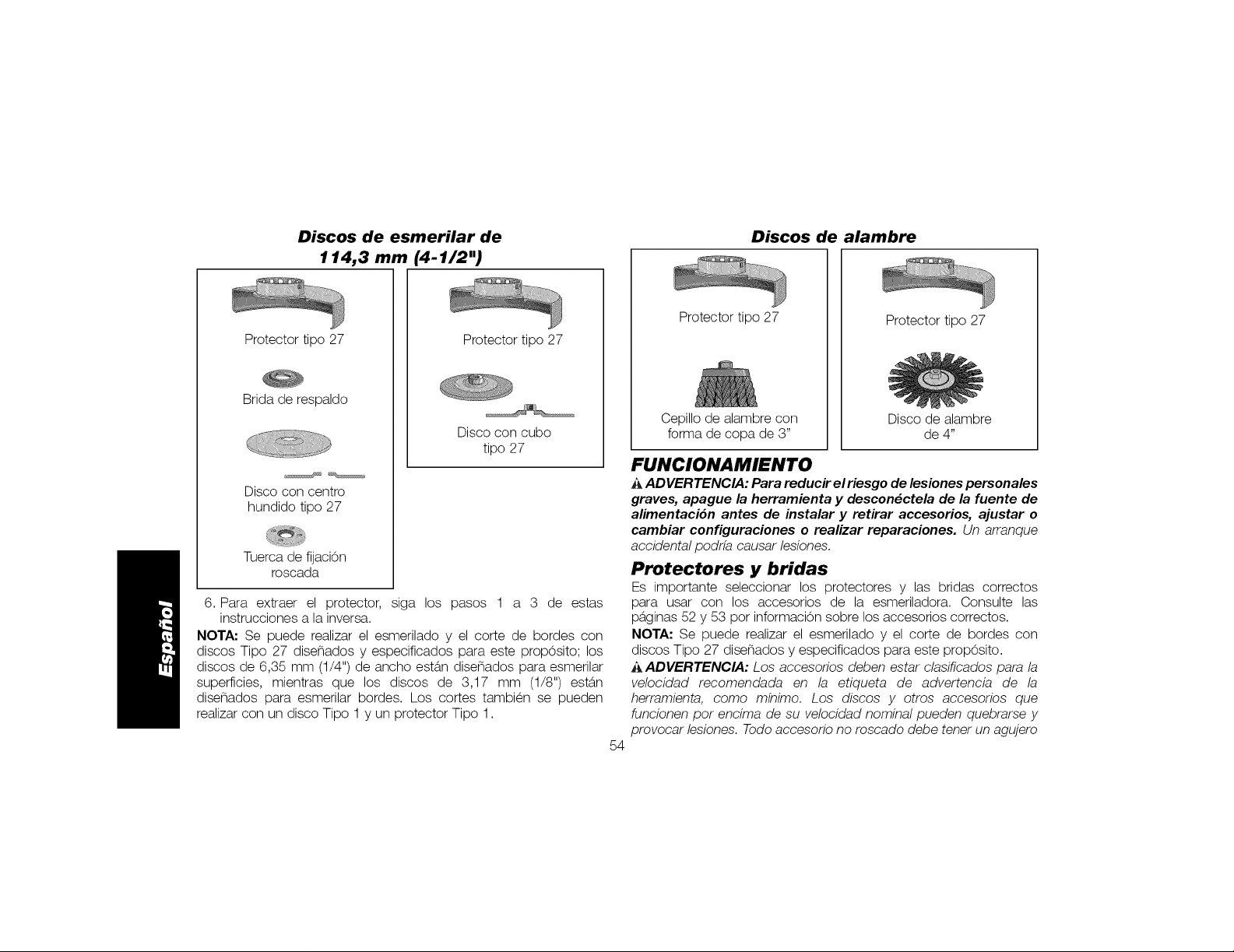
Discos de esmerilar de
114,3 mm (4-1/2")
Discos de alambre
Protector tipo 27
Brida de respaldo
Disco con centro
hundido tipo 27
Tuerca de fijaci6n
roscada
6. Para extraer el protector, siga los pasos 1 a 3 de estas
instrucciones a la inversa.
NOTA: Se puede realizar el esmerilado y el corte de bordes con
discos Tipo 27 dise_ados y especificados para este prop6sito; los
discos de 6,35 mm (1/4") de ancho est6,n dise_ados para esmerilar
superficies, mientras que los discos de 3,17 mm (1/8") est6,n
dise_ados para esmerilar bordes. Los cortes tambien se pueden
realizar con un disco Tipo 1 y un protector Tipo 1.
Protector tipo 27
Disco con cubo
tipo 27
Protector tipo 27
Cepillo de alambre con
forma de copa de 3"
Protector tipo 27
Disco de alambre
de 4"
FUNCIONAMIENTO
A ADVERTENCIA: Para reducir elriesgo de lesiones personales
graves, apague la herramienta y descon_ctela de la fuente de
alimentaci6n antes de instalar y retirar accesorios, ajustar o
cambiar configuraciones o realizar reparaciones. Un arranqoe
accidental podrfa causar lesiones.
Protectores y bridas
Es importante seleccionar los protectores y las bridas correctos
para usar con los accesorios de la esmeriladora. Consulte las
p6,ginas 52 y 53 por informaci6n sobre los accesorios correctos.
NOTA: Se puede realizar el esmerilado y el corte de bordes con
discos Tipo 27 dise_ados y especificados para este prop6sito.
_,ADVERTENOIA: Los accesorios deben estar clasificados para la
velocidad recomendada en la etiqueta de advertencia de la
herramienta, como mfnimo. Los discos y otros accesorios que
funcionen por encima de su velocidad nominal pueden quebrarse y
provocar lesiones. Todo accesorio no roscado debe tener un agujero
54
Page 56

Discos de corte de
114,3 mm (4-1/2")
Discos de
lijar
Discos de lijar de
114,3 mm (4-1/2")
Almohadilla de
Protector tipo 1
Brida de respaldo
Protector tipo 1
Brida de respaldo
respaldo de goma
Disco para lijar
Tuercade fijaci6n
Disco de corte abrasivo
Tuerca de fijaci6n
Disco de corte
de diamante
Tuerca de fijaci6n
para mandril de 7/8". De no ser as_ puede estar disehado para una
sierra circular y no se Iodebe utilizar.Utilice dnicamente los accesorios
que se muestran en las paginas 52 y 53. La velocidad nominal de los
accesorios debe ser superior a la velocidad mfnima aprobada del
disco, indicada en la placa de la herramienta.
Interruptores
_ATENCION: Sostenga la agarradera lateral y el cuerpo de la
herramienta con firmeza para mantener el control de la misma al
Protector tipo 27
Protector tipo 27
Brida de respaldo
Disco de lija
con cubo
roscada
Disco de lija
sin cubo
Tuercade
fijaci6n roscada
encenderla y mientras la utiliza, y hasta que el disco o el accesorio
deje de girar.Asegdrese de que eldisco se ha detenido completamente
antes de depositar la herramienta sobre una superficie.
NOTA" Para reducir los movimientos inesperados de la herra-mienta,
no la encienda ni la apague en condiciones de carga. Permita que
la esmeriladora alcance la velocidad m6.xima antes de aplicarla a la
superficie a esmerilar. Levante la herramienta de la superficie antes
de apagarla. Permita que la herramienta deje de girar antes de
depositarla sobre una superficie.
55
Page 57

INTERRUPTOR DE PALETA (DWE4120, DWE4120N) (FIG. 6)
_ATENCI6N: Antes de conectar la herramienta a una fuente de
alimentacidn presione y suelte el interruptor tipo paleta (H) para
asegurarse de que el interruptor este apagado. Oprima y suelte el
interruptor de paleta, como se describid anteriormente, despues de
que la herramienta sulfa cualquier interrupcidn de energfa, como la
activacidn de un interruptor de corte pot falla a tierra o de un
interruptor automatico, una desconexidn accidental o un corte de
corriente.
Para encender la herramienta, FIG.6
empuje la palanca de bloqueo (J) hacia
la parte posterior de la herramienta,
luego oprima el interruptor de paleta (H).
La herramienta funcionar6, mientras se H
mantenga oprimido el interruptor.
Apague la herramienta soltando el interruptor de paleta.
_,ADVERTENCIA: No anule la palanca de bloqueo. Si se anula la
palanca de bloqueo, la herramienta puede encenderse
sorpresivamente al depositarla sobre una superficie.
INTERRUPTOR DESLIZADOR (FIG. 7)
AADVERTENCIA: Antes de conectar
la herramienta a la toma de corriente, FIG.
asegdrese de que el interruptor
deslizador este en posicidn de
apagado presionando la parte trasera
del interruptor y soltando. Asegdrese G
de que el interruptor deslizador este en
posicidn de apagado, como se
describe mas arriba, despues de
J
cualquier interrupcidn de la alimentacidn electrica a la herramienta,
como pot ejemplo la activacidn de un interruptor diferencial de tierra,
la activacidn de un cortacircuitos, el desenchufe accidental o la
interrupcidn del suministro electrico. Si el interruptor deslizador esta
posicidn de encendido al enchufar la herramienta, esta se pondra en
marcha sdbitamente.
Para poner en funcionamiento la herramienta, deslice el interruptor
de encendido/apagado (ON/OFF) (G) hacia la parte delantera de la
herramienta. Para parar la herramienta, suelte el interruptor deslizador
de encendido/apagado.
Para un funcionamiento continuo, deslice el interruptor hacia la parte
delantera de la herramienta y apriete la parte delantera del interruptor
hacia adentro. Para parar la herramienta mientras est6. funcionando
en modo continuo, apriete la parte trasera del interruptor deslizador
y sueltela.
BOTON DE BLOQUEO (DWE4120) (FIG. 8)
El bot0n de bloqueo (I) ofrece m6.s FIG.8
comodidad en aplicaciones de uso
prolongado. Parabloquear laherramienta,
empuje la palanca de bloqueo (J) hacia la
parte posterior de la herramienta, luego
oprima el interruptor de paleta (H). I
Mientras funciona la herramienta, oprima H J
el bot0n de bloqueo (I). La herramienta
continuar6, funcionando despues de soltar el interruptor de paleta.
Para desbloquear la herramienta, oprima y suelte el interruptor de
paleta. Esto apagar6, la herramienta.
_ATENCI(_N: Permita que la herramienta alcance la velocidad
maxima antes de aplicarla a la superficie de trabajo. Levante la
herramienta de la superficie de trabajo antes de apagarla.
56
Page 58
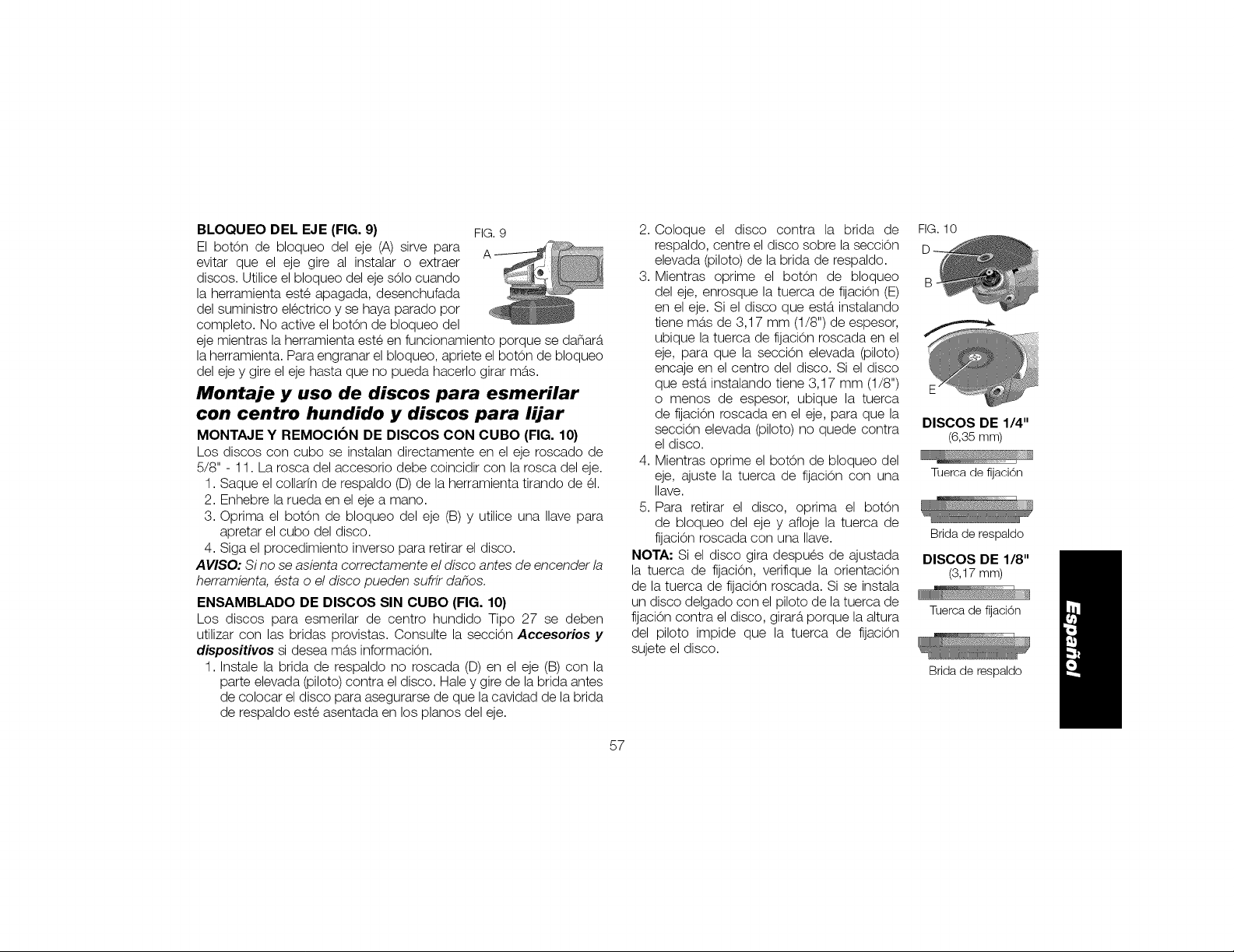
BLOQUEO DEL EJE (FIG. 9) FIG.9
El bot6n de bloqueo del eje (A) sirve para A
evitar que el eje gire al instalar o extraer
discos. Utilice el bloqueo del eje s61ocuando
la herramienta este apagada, desenchufada
del suministro electrico y se haya parado por
completo. No active el bot6n de bloqueo del
eje mientras la herramienta este en funcionamiento porque se da_ara
la herramienta. Para engranar el bloqueo, apriete el bot6n de bloqueo
del eje y gire el eje hasta que no pueda hacerlo girar mas.
Montaje y uso de discos para esmerilar
con centro hundido y discos para lijar
MONTAJE Y REMOCION DE DISCOS CON CUBO (FIG. 10)
Los discos con cubo se instalan directamente en el eje roscado de
5/8" - 11. La rosca del accesorio debe coincidir con la rosca del eje.
1. Saque el collar[n de respaldo (D) de la herramienta tirando de el.
2. Enhebre la rueda en el eje a mano.
3. Oprima el botOn de bloqueo del eje (B) y utilice una Ilave para
apretar el cubo del disco.
4. Siga el procedimiento inverso para retirar el disco.
AVISO: Si no se asienta correctamente el disco antes de encender la
herramienta, esta o el disco pueden sufrir dahos,
ENSAMBLADO DE DISCOS SIN CUBO (FIG. 10)
Los discos para esmerilar de centro hundido Tipo 27 se deben
utilizar con las bridas provistas. Consulte la secciOn Acceseries y
dispesHives si desea m6,s informaciOn.
1. Instale la brida de respaldo no roscada (D) en el eje (B) con la
parte elevada (piloto) contra el disco. Hale y gire de la brida antes
de colocar el disco para asegurarse de que la cavidad de la brida
de respaldo este asentada en los pianos del eje.
2. Coloque el disco contra la brida de
respaldo, centre el disco sobre la secciOn
elevada (piloto) de la brida de respaldo.
3. Mientras oprime el botOn de bloqueo
del eje, enrosque la tuerca de fijaciOn (E)
en el eje. Si el disco que est6, instalando
tiene m6,s de 3,17 mm (1/8") de espesor,
ubique la tuerca de fijaciOn roscada en el
eje, para que la seccion elevada (piloto)
encaje en el centro del disco. Si el disco
que est6, instalando tiene 3,17 mm (1/8")
o menos de espesor, ubique la tuerca
de fijaciOn roscada en el eje, para que la
secciOn elevada (piloto) no quede contra
el disco.
4. Mientras oprime el botOn de bloqueo del
eje, ajuste la tuerca de fijaciOn con una
Ilave.
5. Para retirar el disco, oprima el botOn
de bloqueo del eje y afloje la tuerca de
fijaciOn roscada con una Ilave.
NOTA: Si el disco gira despues de ajustada
la tuerca de fijacion, verifique la orientaciOn
de la tuerca de fijaciOn roscada. Si se instala
un disco delgado con el piloto de la tuerca de
fijaciOncontra el disco, girar6,porque la altura
del piloto impide que la tuerca de fijaciOn
sujete el disco.
FIG. 10
E
DISCOS DE 1/4"
(6,35 mm)
Tuema de fijaci6n
Brida de respaldo
DISCOS DE 1/8"
(3,17mm)
Tuerca de fijaciOn
Brida de respaldo
57
Page 59
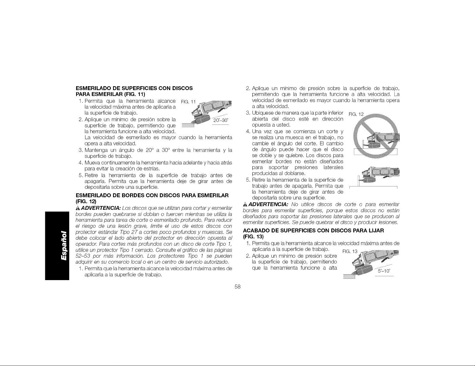
ESMERILADO DE SUPERFICIES CON DISCOS
PARA ESMERILAR (FIG. 11)
1. Permita que la herramienta alcance
la velocidad m6,xima antes de aplicarla a
la superficie de trabajo.
2. Aplique un m[nimo de presiOn sobre la
superficie de trabajo, permitiendo que
la herramienta funcione a alta velocidad.
La velocidad de esmerilado es mayor cuando la herramienta
opera a alta velocidad.
3. Mantenga un 6,ngulo de 20° a 30° entre la herramienta y la
superficie de trabajo.
4. Mueva continuamente la herramienta hacia adelante y hacia atr6,s
para evitar la creaciOn de estrias.
5. Retire la herramienta de la superficie de trabajo antes de
apagarla. Permita que la herramienta deje de girar antes de
depositarla sobre una superficie.
ESMERILADO DE BORDES CON DISCOS PARA ESMERILAR
(FIG. 12)
i_,ADVERTENCIA: Los discos que se utilizan para cortar y esmerilar
bordes pueden quebrarse si doblan o tuercen mientras se utiliza la
herramienta para tarea de corte o esmerilado profundo, Para reducir
el riesgo de una lesidn grave, limite el uso de estos discos con
protector estandar Tipo 27 a cortes poco profundos y muescas. Se
debe colocar el lado abierto del protector en direccidn opuesta al
operador, Para cortes mas profundos con un disco de corte Tipo 1,
utilice un protector Tipo 1 cerrado, Consulte el grafico de las paginas
52-53 por mas informacidn. Los protectores Tipo 1 se pueden
adquirir en su comercio local o en un centro de servicio autorizado.
1. Permita que la herramienta alcance la velocidad m6,xima antes de
aplicarla a la superficie de trabajo.
2. Aplique un m[nimo de presiOn sobre la superficie de trabajo,
permitiendo que la herramienta funcione a alta velocidad. La
velocidad de esmerilado es mayor cuando la herramienta opera
a alta velocidad.
3. Ubfquese de manera que la parte inferior FIG.12
abierta del disco este en direcciOn
opuesta a usted.
4. Una vez que se comienza un corte y
se realiza una muesca en el trabajo, no
cambie el 6,ngulo del corte. El cambio
de 6,ngulo puede hacer que el disco
se doble y se quiebre. Los discos para
}
esmerilar bordes no est6,n dise_ados
para soportar presiones laterales
producidas al doblarse.
5. Retire la herramienta de la superficie de
trabajo antes de apagarla. Permita que i i
la herramienta deje de girar antes de
depositarla sobre una superficie.
_ADVERTENCIA: No utilice discos de corte o para esmerilar
bordes para esmerilar superficies, porque estos discos no estan
disehados para soportar las presiones laterales que se producen al
esmerilar superficies. Se puede quebrar el disco y producir lesiones.
ACABADO DE SUPERFICIES CON DISCOS PARA LIJAR
(FIG. 13)
1. Permita que la herramienta alcance la velocidad m6,xima antes de
aplicarla a la superficie de trabajo. FIG.13
2. Aplique un m[nimo de presiOn sobre
la superficie de trabajo, permitiendo
que la herramienta funcione a alta .............
5_L10o
58
Page 60

velocidad.Lavelocidaddelijadoesmayorcuandolaherramienta
operaaaltavelocidad.
3.Mantengaun6,ngulode5° a 10° entrelaherramientay la
superficiedetrabajo.
4.Muevacontinuamentelaherra-mientahaciaadelantey hacia
atr6,sparaevitarlacreaciOndeestriasenlasuperficiedetrabajo.
5.Retirelaherramientadelasuperficiedetrabajoantesdeapagarla.
Permitaquelaherramientadejedegirarantesdedepositarla
sobreunasuperficie.
MONTAJE DE LAS ALMOHADILLAS DE RESPALDO
PARA LIJAR (FIG. 14)
_ADVERTENCIA: Despues de terminar FIG.14 P
de usar la herramienta para lijar, se debe E--,
reinstalar el protector correcto para el
disco de esmerilar, el disco de lijar, el
cepillo de alambre o el disco de alambre,
1. Ubique o enrosque correctamente la
almohadilla de respaldo roscada (O) en
el eje.
2. Ubique el disco de lijar (P) sobre la
almohadilla de respaldo.
3. Mientras oprime el bloqueo del eje,
enrosque la tuerca de fijaciOn (E)en el
eje, dirigiendo la u_a de la tuerca de
fijaciOnal centro del disco de lijar y la almohadilla de respaldo.
4. Ajuste manualmente la tuerca de fijaciOn. Luego oprima el bot0n
de bloqueo del eje mientras gira el disco de lijar hasta que calcen
el disco de lijary la tuerca de fijacion.
5. Para retirar el disco, tome y gire la almohadilla de respaldo y la
almohadilla de lijar mientras oprime el bot0n de bloqueo del eje.
USO DE ALMOHADILLAS DE RESPALDO PARA LIJAR
(FIG. 15)
Seleccione el papel de lija del grano correcto para su aplicaci0n.
El papel de lija tiene diversos granos. Los granos gruesos retiran
material con m6,s rapidez y producen un acabado m6,s6,spero. Los
granos m6,s finos retiran material m6,s lentamente y producen un
acabado m6,s liso.
Comience con discos de grano grueso para retirar material
groseramente, con m6,s rapidez Luego pase a un papel de grano
mediano y termine con un disco de grano fino para un acabado
Optimo.
Grano grueso 16 a 30
Grano mediano 36 a 80
Acabado fino 100 a 120
Acabado muy fino 150 a 180
1. Permita que la herramienta alcance la velocidad m6,xima antes de
aplicarla a la superficie de trabajo.
2. Aplique un m[nimo de presiOnsobre la FIG.15
superficie de trabajo, permitiendo que
la herramienta funcione a alta
velocidad. La velocidad de lijado es
mayor cuando la herramienta opera a
alta velocidad. 5_15°
3. Mantenga un 6,ngulo de 5° a 15°
entre la herramienta y la superficie de
trabajo. El disco de lijadebe contactar 2,5 cm (1") de lasuperficie
de trabajo, aproximadamente.
4. Mueva la herramienta constantemente en una linea recta para no
quemar ni marcar drculos en la superficie de trabajo. Apoyar la
herramienta sobre la superficie de trabajo, sin moverla, o mover la
herramienta en drculos provoca quemaduras y marcas circulares
sobre la superficie.
59
J
Page 61

5.Retirela herramientade lasuperficiede trabajoantesde
apagarla.Permitaquelaherramientadejedegirarantesde
depositarlasobreunasuperficie.
Montaje y uso de cepillos de alambre
y discos de alambre
Los cepillos de alambre con forma de copa o losdiscos de alambre
se atornillan directamente en el eje de la esmeriladora sin utilizar
bridas. Utilice Onicamente cepillos de alambre o discos de alambre
provistos con cubo roscado de 5/8"-11. Se requiere un protector
Tipo 27 cuando se usan cepillos y discos de alambre.
_ATENCION: Use guantes de trabajo cuando manipula
cepillos y discos de alambre. Pueden tenet filos.
i_ATENCI6N: El disco o el cepillo no deben tocar el protector
cuando se los ensambla ni cuando estan en uso. Puede provocar un
daho indetectable al accesorio, haciendo que los alambres se
desprendan del disco o el cubo del accesorio.
MONTAJE DE CEPILLOS DE ALAMBRE CON FORMA DE
COPA Y DISCOS DE ALAMBRE
1. Enroque el disco en el eje manualmente.
2. Oprima el botOn de bloqueo del eje y utilice una Ilave en el cubo
del disco o cepillo de alambre para apretar el disco.
3. Para retirar el disco, siga el procedimiento inverso.
AVISO: Si no se asienta correctamente el cubo del disco antes de
encender la herramienta, esta o el disco pueden sufrir dahos.
USO DE CEPILLOS DE ALAMBRE CON FORMA DE COPA Y
DISCOS DE ALAMBRE (FIG 16, 17)
Los discos y los cepillos de alambre se pueden utilizar para eliminar
6xido, escamas y pintura, y para alisar superficies irregulares.
1. Permita que la herramienta alcance la velocidad m6.xima antes de
aplicarla a la superficie de trabajo.
2. Aplique un m[nimo de presiOn sobre la superficie de trabajo,
permitiendo que la herramienta funcione a alta velocidad.
La velocidad de remociOn de material es mayor cuando la
herramienta opera a alta velocidad.
3. Mantenga un 6.ngulo de 5° a 10°entre la FIG.16
herramienta y la superficie de trabajo
para los cepillos de alambre con forma
de copa.
4. Con las ruedas de alambre, mantenga
contacto entre el borde del disco y la
superficie de trabajo.
5. Mueva continuamente la herramienta hacia FIG.17
adelante y hacia atr6.s para evitar la creaciOn
de estr[as. Apoyar la herramienta sobre la
superficie de trabajo, sin moverla, o mover la
herramienta en drculos provoca quemaduras
y marcas circulares sobre la superficie.
6. Retire laherramienta de la superficie de trabajo antes de apagarla.
Permita que la herramienta deje de girar antes de depositarla
sobre una superficie.
i_ATENCI6N: Tenga especial cuidado cuando trabaje sobre un
borde, ya que se puede producir un movimiento fuerte y sdbito de la
esmeriladora.
6O
Page 62
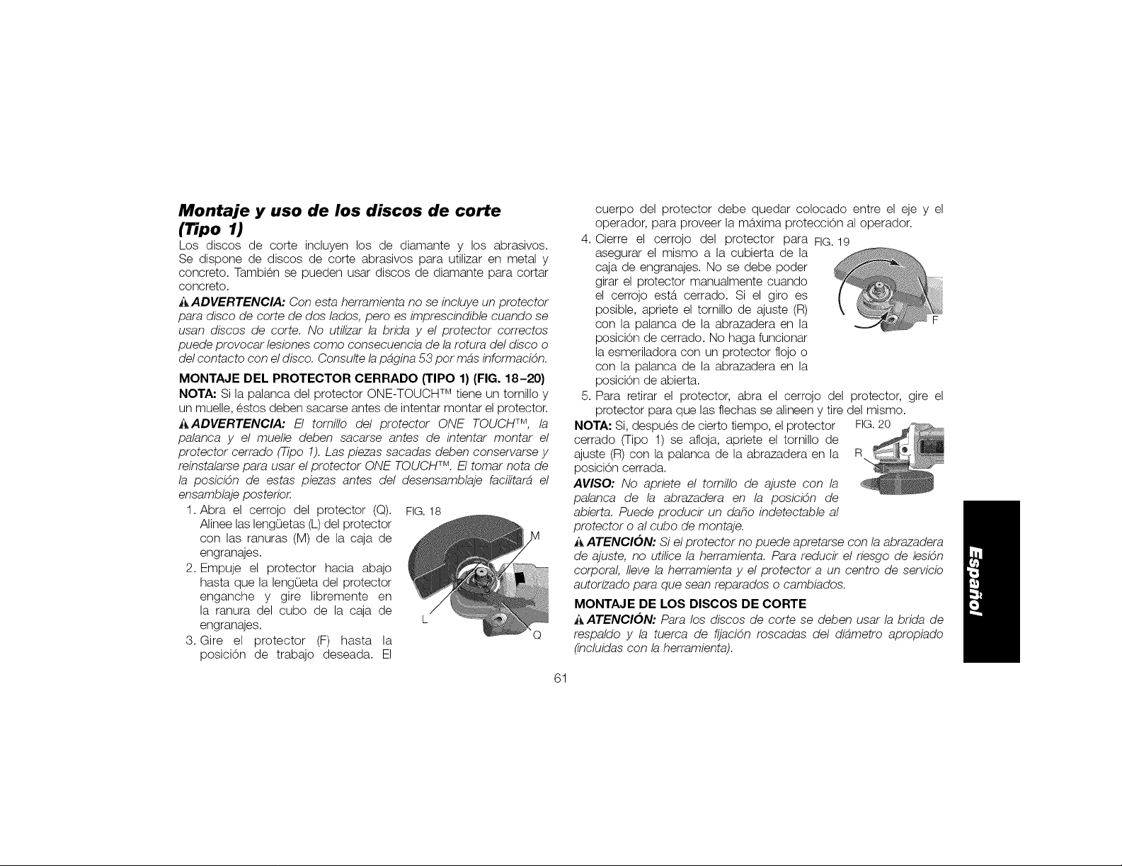
Montaje y uso de los discos de corte
(1ipo 1)
Los discos de corte incluyen los de diamante y los abrasivos.
Se dispone de discos de corte abrasivos para utilizar en metal y
concreto. Tambien se pueden usar discos de diamante para cortar
concreto.
A ADVERTENCIA: Con esta herramienta no se incluye un protector
para disco de corte de dos lados, pero es imprescindible cuando se
usan discos de corte. No utilizar la brida y el protector correctos
puede provocar lesiones como consecuencia de la rotura del disco o
del contacto con el disco. Consulte la pagina 53 por mas informacidn.
MONTAJE DEL PROTECTOR CERRADO (TIPO 1) (FIG. 18-20)
NOTA: Si la palanca del protector ONE-TOUCH TM tiene un tornillo y
un muelle, estos deben sacarse antes de intentar montar el protector.
i_ADVERTENCIA: El tomillo del protector ONE TOUCH TM, la
palanca y el muelle deben sacarse antes de intentar montar el
protector cerrado (Tipo 1). Las piezas sacadas deben conservarse y
reinstalarse para usar el protector ONE TOUCHTM. El tomar nota de
la posicidn de estas piezas antes del desensamblaje facilitara el
ensamblaje posterior.
1. Abra el cerrojo del protector (Q). FIG.18
Alinee las leng0etas (L) del protector
con las ranuras (M) de la caja de
engranajes.
2. Empuje el protector hacia abajo
hasta que la leng0eta del protector
enganche y gire libremente en
la ranura del cubo de la caja de
engranajes. L
3. Gire el protector (F) hasta la Q
posiciOn de trabajo deseada. El
cuerpo del protector debe quedar colocado entre el eje y el
operador, para proveer la m6.xima protecciOn al operador.
4,
Cierre el cerrojo del protector para FIG.19
asegurar el mismo a la cubierta de la
caja de engranajes. No se debe poder
girar el protector manualmente cuando
el cerrojo est6. cerrado. Si el giro es
posible, apriete el tornillo de ajuste (R)
con la palanca de la abrazadera en la F
posiciOn de cerrado. No haga funcionar
la esmeriladora con un protector flojo o
con la palanca de la abrazadera en la
posiciOn de abierta.
5. Para retirar el protector, abra el cerrojo del protector, gire el
protector para que las flechas se alineen y tire del mismo.
NOTA" Si, despues de cierto tiempo, el protector FIG.20
cerrado (Tipo 1) se afloja, apriete el tornillo de
ajuste (R) con la palanca de la abrazadera en la R
posiciOn cerrada.
AVISO: No apriete el tomillo de ajuste con la
palanca de la abrazadera en la posicidn de
abierta. Puede producir un daho indetectable al
protector o al cubo de montaje.
ATENCION: Si el protector no puede apretarse con la abrazadera
de ajuste, no utilice la herramienta. Para reducir el riesgo de lesidn
corporal, Ileve la herramienta y el protector a un centro de servicio
autorizado para que sean reparados o cambiados.
MONTAJE DE LOS DISCOS DE CORTE
i_ATENCI(_N: Para los discos de corte se deben usar la brida de
respaldo y la tuerca de fljacidn roscadas del diametro apropiado
(incluidas con la herramienta).
61
Page 63

1.Ubiquelabridaderespaldosinroscaenelejeconlaseccion
elevada(piloto)haciaarriba.LasecciOnelevada(piloto)delabrida
derespaldoestar6,contraeldiscocuandoseinstaleelmismo.
2.Ubiqueeldiscoenlabridaderespaldo,centrandoeldiscoenla
secciOnelevada(piloto).
3.InstalelatuercadefijaciOnroscadaconlasecciOnelevada
(piloto)endirecciOnopuestaaldisco.
4.Oprimaelbot0ndebloqueodelejeyajustelatuercadefijaciOn
conunaIlave.
5.Pararetirareldisco,tOmeloygfrelomientrasoprimeelbotOnde
bloqueodeleje.
USO DE DISCOS DE CORTE (FIG. 21)
_ADVERTENCIA: No utilice discos de corte o para esmerilar
bordes para esmerilar superficies, porque estos discos no estan
disehados para soportar las presiones laterales que se producen al
esmerilar superficies. Se puede quebrar el disco y producir lesiones.
1. Permita que la herramienta alcance la
velocidad m6.xima antes de aplicarla a
la superficie de trabajo.
2. Aplique un m[nimo de presiOn sobre
la superficie de trabajo, permitiendo
que la herramienta funcione a alta
velocidad. La velocidad de corte es
mayor cuando la herramienta opera a
alta velocidad.
3. Una vez que se comienza un corte y
se realiza una muesca en el trabajo,
no cambie el 6.ngulo del corte. El
cambio de 6.ngulo puede hacer que el
disco se doble y se quiebre.
4. Retire la herramienta de la superficie de trabajo antes de
apagarla. Permita que la herramienta deje de girar antes de
depositarla sobre una superficie.
MANTENIMIENTO
_ ADVERTENCIA: Para reducir el riesgo de lesiones personales
graves, apague la herramienta y descon_ctela de la fuente de
alimentacidn antes de instalar y retirar accesorios, ajustar o
cambiar configuraciones o realizar reparaciones. Un arranque
accidental podrfa causar lesiones.
Limpieza
_.ADVERTENCIA: Sople la suciedad y el polvo de todos los
conductos de ventilacidn con aire seco, al menos una vez pot
semana. Para reducir el riesgo de lesiones, utilice siempre proteccidn
para los ojos aprobada ANSI Z87.1 al realizar esta tarea.
i_,ADVERTENCIA: Nunca utilice solventes ni otros qufmicos
abrasivos para limpiar las piezas no metalicas de la herramienta.
Estos productos qufmicos pueden debilitar los materiales plasticos
utilizados en estas piezas. Utilice un paho humedecido s61ocon agua
y jabdn neutro. Nunca permita que penetre Ifquido dentro de la
herramienta ni sumerja ninguna de las piezas en un Ifquido.
Accesorios
_ADVERTENCIA: Debido a que no se han probado con este
producto otros accesorios que no sean los que ofrece DEWALT, el
uso de dichos accesorios con esta herramienta podrfa ser peligroso.
Para reducir el riesgo de lesiones, con este producto deben usarse
s61olos accesorios recomendados pot DEWALT.
Los accesorios que se recomiendan para utilizar con la herramienta
est6.n disponibles a un costo adicional en su distribuidor local o
en un centro de mantenimiento autorizado. Si necesita ayuda
para Iocalizar alg0n accesorio, pOngase en contacto con
62
Page 64
DFWALTIndustrialToolCo.,701EastJoppaRoad,Baltimore,
MD 21286,Ilameal 1-800-4-DEWALT(1-800-433-9258)o
visitenuestrositioWeb:www.dewalt.com.
Reparaciones
Para asegurar la SEGURIDAD y la CONFIABILIDAD del producto,
las reparaciones, el mantenimiento y los ajustes deben (inclusive
inspecciOn y cambio de carbones) ser realizados en un centro de
mantenimiento en la f6,brica DEWALT,en un centro de mantenimiento
autorizado DFWALT u por otro personal de mantenimiento calificado.
Utilice siempre piezas de repuesto identicas.
PARA REPARACION Y SERVICIO DE SUS HERRAMIENTAS
ELI_CTRICAS, FAVOR DE DIRIGIRSE AL CENTRO DE
SERVICIO MAS CERCANO
CULIACAN, SIN
Blvd.EmilianoZapata5400-1 Poniente
Col. San Rafael (667)717 89 99
GUADALAJARA, JAL
Av.La Paz#1779 - Col. AmericanaSectorJub,rez (33)3825 6978
MEXICO, D.F.
EjeCentralL_,zaroCb,rdenasNo. 18
LocalD, Col. Obrera (55)5588 9377
MERIDA, YUC
Calle 63 #459-A - Col. Centro (999) 928 5038
MONTERREY, N.L.
Av. Francisco I. Madero 831 Poniente - Col. Centro (818) 375 23 13
PUEBLA, PUE
17 Norte #205 - Col. Centro (222) 246 3714
QUERETARO, QRO
Av. San Roque 274 - Col. San Gregorio (442) 2 17 63 14
SAN LUlS POTOSI, SLP
Av. Universidad 1525 - Col. San Luis (444) 814 2383
TORREON, COAH
Blvd. Independencia, 96 Pte. - Col. Centro (871) 716 5265
VERACRUZ, VER
ProlongaciOn D[az Mir0n #4280 - Col. Remes (229) 921 7016
VILLAHERMOSA, TAB
ConstituciOn 516-A- Col. Centro (993) 312 5111
PARA OTRAS LOCALIDADES:
Si se encuentra en M_xico, por favor Ilame al (55) 5326 7100
Si se encuentra en U.S., por favor Ilame al
1-800-433-9258 (1-800 4-DEWALT)
P61iza de Garantia
IDENTIFICACION DEL PRODUCTO:
Sello o firma del Distribuidor.
Nombre del producto: Mod./Cat.:
Marca: NOm. de serie:
(Datos para ser Ilenados por el distribuidor)
Fecha de compra y/o entrega del producto:
Nombre y domicilio del distribuidor donde se adquiriO el producto:
Este producto est6, garantizado por un a_o a partir de la fecha de
entrega, contra cualquier defecto en su funcionamiento, as[ como
en materiales y mano de obra empleados para su fabricaciOn.
Nuestra garant[a incluye la reparaciOn o reposiciOn del producto y/o
componentes sin cargo alguno para el cliente, incluyendo mano
de obra, as[ como los gastos de transportaciOn razonablemente
erogados derivados del cumplimiento de este certificado.
63
Page 65

Parahacerefectivaestagarant[adeber6,presentarsuherramientay
estapOlizaselladaporelestablecimientocomercialdondeseadquiriO
elproducto,denocontarconesta,bastar6,lafacturadecompra.
EXCEPCION ES
Esta garant[a no ser6,v6,1idaen los siguientes casos:
• Cuando el producto se hubiese utilizado en condiciones
distintas alas normales;
• Cuando el producto no hubiese sido operado de acuerdo con
el instructivo de uso que se acompa_a;
• Cuando el producto hubiese sido alterado o reparado por
personas distintas alas enlistadas al final de este certificado.
Anexo encontrar6, una relaciOn de sucursales de servicio de f6,brica,
centros de servicio autorizados y franquiciados en la Rep0blica
Mexicana, donde podr6, hacer efectiva su garant[a y adquirir partes,
refacciones y accesorios originales.
Registro en linea
Gracias por su compra. Registre su producto ahora para:
• SERVICIO EN GARANT|A: Si completa esta tarjeta, podr6,
obtener un servicio en garant[a m6,s eficiente, en caso de que
exista un problema con su producto.
• CONFIRMATCI([)N DE PROPIEDAD: En caso de una perdida
que cubra el seguro, como un incendio, una inundation o un
robo, el registro de propiedad servir6, como comprobante de
compra.
• PARA SU SEGURIDAD: Si registra el producto, podremos
comunicarnos con usted en el caso improbable que se deba
enviar una notificaciOn de seguridad conforme a la Federal
Consumer Safety Act (Ley Federal de Seguridad de Productos
para el Consumidor).
Registro en linea en www.dewalt.com/register.
Garantia limitada por tres ados
DFWALT reparar6,, sin cargo, cualquier falla que surja de defectos
en el material o la fabricaciOn del producto, por hasta tres a_os a
contar de la fecha de compra. Esta garant[a no cubre fallas de las
piezas causadas por su desgaste normal o abuso a la herramienta.
Para mayores detalles sobre la cobertura de la garant[a e informaciOn
acerca de reparaciones realizadas bajo garant[a, vidtenos en www.
dewalt.com o dirigase al centro de servicio m6,s cercano. Esta
garant[a no aplica a accesorios o a da_os causados por reparaciones
realizadas o intentadas por terceros. Esta garant[a le otorga derechos
legales espedficos, adem6,s de los cuales puede tener otros
dependiendo del estado o la provincia en que se encuentre.
Adem6,s de la garant[a, las herramientas DEWALT est6,n cubiertas
por:
1 AI_IO DE SERVICIO GRATUITO
DEWALT mantendr6, la herramienta y reemplazar6, las piezas
gastadas por su uso normal, sin cobro, en cualquier momento
durante un a_o a contar de la fecha de compra. Los art[culos
gastados por la clavadora, tales como la unidad de hoja y retorno del
impulsador, no est6,n cubiertas.
GARANT|A DE REEMBOLSO DE SU DINERO POR 90 D|AS
Si no est6, completamente satisfecho con el desempe_o de su
m6,quina herramienta, Ib,ser o clavadora DEWALT, cualquiera sea el
motivo, podr6, devolverlo hasta 90 dias de la fecha de compra con su
recibo y obtener el reembolso completo de su dinero - sin necesidad
de responder a ninguna pregunta.
AM#RICA LATINA: Esta garant[a no se aplica a los productos que
se venden en America Latina. Para los productos que se venden
en America Latina, debe consultar la informaciOn de la garant[a
espec[fica del pals que viene en el empaque, Ilamar a la compa_[a
local o visitar el sitio Web a fin de obtener esa informaciOn.
64
Page 66
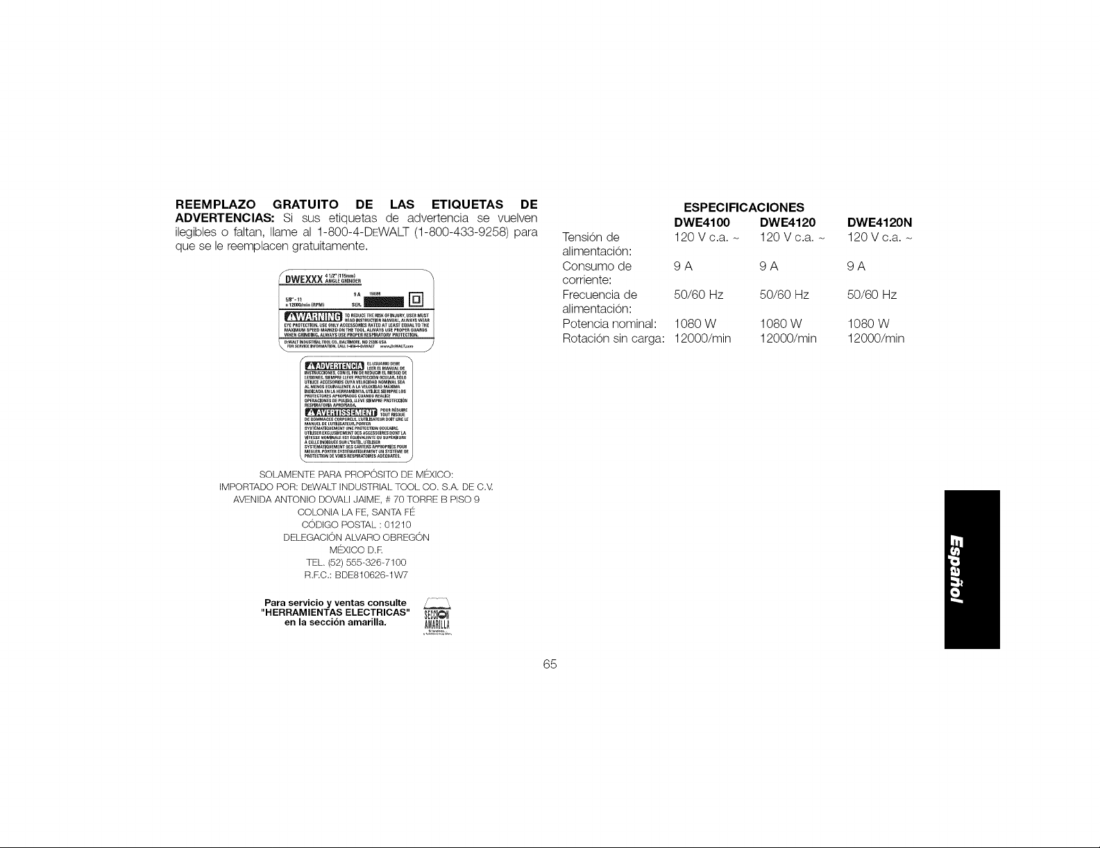
REEMPLAZO GRATUITO DE LAS ETIQUETAS DE
ADVERTENCIAS: Si sus etiquetas de advertencia se vuelven
ilegibles o faltan, Ilame al 1-800-4-DEWALT (1-800-433-9258) para
que se le reemplacen gratuitamente.
41/2"(115m,__DWEXXX AN_LEG._NDE"
n1200_/min(RFM} S£_.
_R_0 INS_UCT_NMANUALALWAYSWEA_
EYEP_0TE_0N.USE0_LYACCESS0RI_S_TE0 A_LEASTE_UALTOT_
MAXlMU_SPEEDM_RKED0_ THETOOL.ALWAYSUSEPROPE__UARDS
WHENG_INOiNG.ALWAYSUSEpROPERRESPIRATORYPROT_CTION,
INSTRU_CI_NEI CON _L AN 0E _E_UCIR _L RIES6_ _
ALM_O_E_UIVALE_TE_LAVELOCiDA_M_XlMA
P_0TECTORESA_ROPIA_0SC_AN00R_ALICE
OPE_CiO_S_ P_LI_O,_-_/_SiENPREP_OTE_CI_N
_ESpIRAT0_IAAPRONAD_. POUR_1_1_£
_£OONMA_£S_i]RPORgLS,t;t_TiLISATEUR_OITLI_ELE
_TI_SE_EXCLUSI_N_NTo_s_CCESS01_ES_0_TL_
_EtZ_INOlaU_ESU__'0U_ILL_US_
SOL_,MENTE PARA PROPOSITO DE MF!_XICO:
IMPORfADO POR: DEWAL;[ INDUSTRIAL TOOL CO. S.A. DE C,V,
AW!!!NIDAANTONIO DOW_,LIJAIME, # 70 TORRE B PISO 9
COLONIA LA FE, SANTA F_!_
CODIGO POSTAL: 01210
DELEGACION AL.VARO OBREGON
Para servicio y ventas consulte /..... ',,
"HERRAMIENTAS ELECTRICAS" _CCJ@_
en la secciOn amarilla. _M!_
DEWALTIndustrialToolCo.,701EastJoppaRoad,Baltimore,MD21286
(DEC12)PartNo.N157456DWE4100,DWE4120,DWE4120NCopyright©2012DEWALT
ThefollowingaretrademarksforoneormoreDEWALTpowertools:theyellowandblackcolorscheme;the"D"shapedairintakegrill;thearray
ofpyramidsonthehandgrip;thekitboxconfiguration;andthearrayoflozenge-shapedhumpsonthesurfaceofthetool.
 Loading...