

DeWalt DW907, DW926 Instruction Manual

INSTRUCTION MANUAL
GUIDE D'UTILISATION
MANUAL DE INSTRUCCIONES
DW907, DW926
Cordless Adjustable Clutch Driver/Drill
Perceuse-tournevis sans fil à embrayage réglable
Taladro/Destornillador Inalámbrico con Embrague Ajustable
INSTRUCTIVO DE OPERACIÓN, CENTROS DE SERVICIO Y PÓLIZA
DE GARANTÍA. ADVERTENCIA: LÉASE ESTE INSTRUCTIVO
ANTES DE USAR EL PRODUCTO.
IF YOU HAVE ANY QUESTIONS OR COMMENTS ABOUT THIS OR ANY DEWALT TOOL,
CALL US TOLL FREE AT:
1-800-4-DEWALT (1-800-433-9258)
General Safety Rules – For All Battery Operated Tools
WARNING! Read and understand all instructions. Failure to follow all instructions listed
below may result in electric shock, fire and/or serious personal injury.
SAVE THESE INSTRUCTIONS
WORK AREA
•
Keep your work area clean and well lit. Cluttered benches and dark areas invite accidents.
•
Do not operate power tools in explosive atmospheres, such as in the presence of flammable liquids, gases, or dust. Power tools create sparks which may ignite the dust or
fumes.
•
Keep bystanders, children, and visitors away while operating a power tool. Distractions
can cause you to lose control.
ELECTRICAL SAFETY
•
A battery operated tool with integral batteries or a separate battery pack must be
recharged only with the specified charger for the battery. A charger that may be suitable
for one type of battery may create a risk of fire when used with another battery.
•
Use battery operated tool only with the specifically designated battery pack. Use of any
other batteries may create a risk of fire.
PERSONAL SAFETY
•
Stay alert, watch what you are doing and use common sense when operating a power
tool. Do not use tool while tired or under the influence of drugs, alcohol, or medication. A
moment of inattention while operating power tools may result in serious personal injury,
•
Dress properly. Do not wear loose clothing or jewelry. Contain long hair. Keep your hair,
clothing, and gloves away from moving parts. Loose clothing, jewelry, or long hair can be
caught in moving parts.
Air vents often cover moving parts and should also be avoided.
• Avoid accidental starting. Be sure switch is in the locked or off position before inserting bat-
tery pack. Carrying tools with your finger on the switch or inserting the battery pack into a tool
with the switch on invites accidents.
•
Remove adjusting keys or wrenches before turning the tool on. A wrench or a key that
is left attached to a rotating part of the tool may result in personal injury.
•
Do not overreach. Keep proper footing and balance at all times. Proper footing and balance
enables better control of the tool in unexpected situations.
•
Use safety equipment. Always wear eye protection. Dust mask, non-skid safety shoes,
hard hat, or hearing protection must be used for appropriate conditions.
TOOL USE AND CARE
•
Use clamps or other practical way to secure and support the workpiece to a stable
platform. Holding the work by hand or against your body is unstable and may lead to a loss
of control.
•
Do not force tool. Use the correct tool for your application. The correct tool will do the
job better and safer at the rate for which it is designed.
•
Do not use tool if switch does not turn it on or off. A tool that cannot be controlled with
the switch is dangerous and must be repaired.
•
Disconnect battery pack from tool or place the switch in the locked or off position
before making any adjustments, changing accessories, or storing the tool. Such pre-
ventative safety measures reduce the risk of starting the tool accidentally.
•
Store idle tools out of reach of children and other untrained persons. Tools are dangerous in the hands of untrained users.
•
When battery pack is not in use, keep it away from other metal objects like: paper
clips, coins, keys, nails, screws, or other small metal objects that can make a connection from one terminal to another. Shorting the battery terminals together may cause
sparks, burns, or a fire.
•
Maintain tools with care. Keep cutting tools sharp and clean. Properly maintained tools,
with sharp cutting edges are less likely to bind and are easier to control.
•
Check for misalignment or binding of moving parts, breakage of parts, and any other
condition that may affect the tools operation. If damaged, have the tool serviced before
using. Many accidents are caused by poorly maintained tools.
•
Use only accessories that are recommended by the manufacturer for your model.
Accessories that may be suitable for one tool, may create a risk of injury when used on
another tool.
SERVICE
•
Tool service must be performed only by qualified repair personnel. Service or maintenance performed by unqualified personnel result in a risk of injury.
•
When servicing a tool, use only identical replacement parts. Follow instructions in the
Maintenance section of this manual. Use of unauthorized parts or failure to follow
Maintenance Instructions may create a risk of shock or injury.
Additional Safety Rules
•
Hold tool by insulated gripping surfaces when performing an operation where the cutting tool may contact hidden wiring or its own cord. Contact with a “live” wire will make
exposed metal parts of the tool “live” and shock the operator.
CAUTION: Wear appropriate personal hearing protection during use. Under some con-
ditions and duration of use, noise from this product may contribute to hearing loss.
CAUTION: Some tools with large battery packs will stand upright on the battery pack but may
be easily knocked over. When not in use, place tool on its side on a stable surface where it will
not cause a tripping or falling hazard.
WARNING: Some dust created by power sanding, sawing, grinding, drilling, and other con-
struction activities contains chemicals known to cause cancer, birth defects or other reproductive harm. Some examples of these chemicals are:
• lead from lead-based paints,
• crystalline silica from bricks and cement and other masonry products, and
• arsenic and chromium from chemically-treated lumber (CCA).
Your risk from these exposures varies, depending on how often you do this type of work. To
reduce your exposure to these chemicals: work in a well ventilated area, and work with
approved safety equipment, such as those dust masks that are specially designed to filter out
microscopic particles.
• Avoid prolonged contact with dust from power sanding, sawing, grinding, drilling,
and other construction activities. Wear protective clothing and wash exposed areas
with soap and water. Allowing dust to get into your mouth, eyes, or lay on the skin may pro-
mote absorption of harmful chemicals.
WARNING: Use of this tool can generate and/or disburse dust, which may cause serious and
permanent respiratory or other injury. Always use NIOSH/OSHAapproved respiratory protection
appropriate for the dust exposure. Direct particles away from face and body.
• The label on your tool may include the following symbols.
V ..................volts A ....................amperes
Hz ................hertz W ....................watts
min................minutes ..................alternating current
..............direct current
n
o....................no load speed
..................
Class II Construction
......................
earthing terminal
..................safety alert symbol .../min ..............revolutions per minute
SAVE THESE INSTRUCTIONS
Introduction
Some chargers are designed to use standard 120 volt AC, 60 Hz power. A vehicular charger will
charge from 12 volts through a cigarette lighter socket. Charge time is approximately one hour.
Extended Run-Time battery packs may require slightly longer charge.
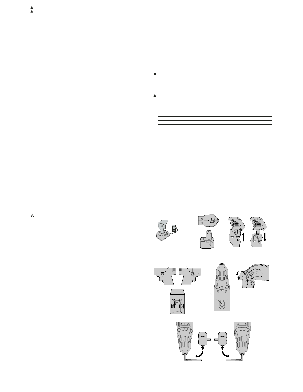
Charging Procedure (Fig. 1)
These chargers require no adjustment and are designed to be as easy as possible to operate.
Simply place your battery pack into the receptacle of a plugged in charger (Fig. 1) and it will automatically charge the pack.
PROBLEM POWER LINE
If your charger has a Problem Power Line indicator: When the charger is used with some
portable power sources such as generators or sources that convert DC to AC, the charger may
temporarily suspend operation, flashing the red light with two fast blinks followed by a
pause. This indicates the power source is out of limits.
HOT/COLD PACK DELAY
If the charger detects a battery that is hot or excessively cold, it automatically starts a Hot/Cold
Pack Delay, suspending charging until the battery temperature has stabilized. The charger
automatically switches to the Pack Charging mode. This feature ensures maximum battery life.
The red light flashes long, then short while in the Hot/Cold Pack Delay mode.
Installing and Removing the Battery Pack (Fig. 2 & 3)
NOTE: Make sure your battery pack is fully charged.
To install the battery pack into the tool handle, align the base of the tool with the notch inside the
tool’s handle (Fig. 2) and slide the battery pack firmly into the handle until you hear the lock snap
into place. To remove the battery pack from the tool, press the release buttons and firmly pull
the battery pack out of the tool handle as shown in Fig. 3. Insert it into the charger as described
in the charger section of this manual.
NOTE: Battery storage and carrying caps are provided for use whenever the battery
is out of the tool or charger. Remove cap before placing battery in charger or tool.
WARNING: Do not store or carry battery so that metal objects can contact
exposed battery terminals. For example, do not place battery in aprons, pockets,
tool boxes, product kit boxes, drawers, etc., with loose nails, screws, keys, etc.
without battery cap. Transporting batteries can possibly cause fires if the
battery terminals inadvertently come in contact with conductive materials such as keys,
coins, hand tools and the like. The US Department of Transportation Hazardous Material
Regulations (HMR) actually prohibit transporting batteries in commerce or on airplanes (i.e.,
packed in suitcases and carry-on luggage) UNLESS they are properly protected from short
circuits. So when transporting individual batteries, make sure that the battery terminals are
protected and well insulated from materials that could contact them and cause a short circuit.
Important Charging Notes
1. Longest life and best performance can be obtained if the battery pack is charged when the air
temperature is between 65°F and 75°F (18°- 24°C). DO NOT charge the battery pack in an air
temperature below +40°F(+4.5°C), or above +105°F (+40.5°C). This is important and will
prevent serious damage to the battery pack.
2. The charger and battery pack may become warm to touch while charging. This is a normal
condition, and does not indicate a problem. To facilitate the cooling of the battery pack after
use, avoid placing the charger or battery pack in a warm environment such as in a metal shed,
or an uninsulated trailer.
3. If the battery pack does not charge properly — (1) Check current at receptacle by plugging in
a lamp or other appliance, (2) Check to see if receptacle is connected to a light switch which
turns power off when you turn out the lights. (3) Move charger and battery pack to a location
where the surrounding air temperature is approximately 65°F - 75°F (18°- 24°C). (4) If
charging problems persist, take or send the tool, battery pack and charger to your local service
center.
4. The battery pack should be recharged when it fails to produce sufficient power on jobs which
were easily done previously. DO NOT CONTINUE to use under these conditions. Follow the
charging procedure. You may also charge a partially used pack whenever you desire with no
adverse affect on the battery pack.
5. Under certain conditions, with the charger plugged in to the power supply, the exposed charging
contacts inside the charger can be shorted by foreign material. Foreign materials of a
conductive nature such as, but not limited to, steel wool, aluminum foil, or any buildup of metallic
particles should be kept away from charger cavities. Always unplug the charger from the power
supply when there is no battery pack in the cavity. Unplug charger before attempting to clean.
6. Do not immerse charger in water or any other liquid.
DEWALT Industrial Tool Co., 701 East Joppa Road, Baltimore, MD 21286
(AUG04) Form No. 626686-00 DW907, DW926 Copyright © 1999, 2003, 2004 D
EWALT
The following are trademarks for one or more D
EWALTpower tools: the yellow and black color scheme; the
“D” shaped air intake grill; the array of pyramids on the handgrip; the kit box configuration; and the array of
lozenge-shaped humps on the surface of the tool.
Questions? See us in the World Wide Web at www.dewalt.com
WARNING: Don't allow any liquid to get inside charger. Electric shock may result.
CAUTION: Never attempt to open the battery pack for any reason. If the plastic housing of the
battery pack breaks or cracks, return to a service center for recycling.
Important!
This product is not user servicable. There are no user servicable parts inside the charger.
Servicing at an authorized service center is required to avoid damage to static sensitive internal
components.
READ ALL OF THE INSTRUCTIONS IN THE BATTERY CHARGER MANUAL BEFORE
ATTEMPTING TO CHARGE THE BATTERY PACK FOR YOUR TOOL.
Always use correct battery pack (pack supplied with tool or upgrade to an XR pack.) Never install
any other battery pack. It will ruin your tool and may create a hazardous condition.
Variable Speed Switch (Fig. 4)
To turn the tool on, squeeze the trigger switch (A). To turn the tool off, release the trigger switch.
Your tool is equipped with a brake. The chuck will stop as soon as the trigger switch is fully
released.
The variable speed switch enables you to select the best speed for a particular application. The
farther you squeeze the trigger, the faster the tool will operate. Use lower speeds for starting
holes without a centerpunch, drilling in metals or plastics, driving screws and drilling ceramics,
or in any application requiring high torque. Higher speeds are better for drilling in wood, wood
compositions and for using abrasive and polishing accessories. For maximum tool life, use variable speed only for starting holes or fasteners.
NOTE: Continuous use in variable speed range is not recommended. It may damage the switch
and should be avoided.
Forward/Reverse Control Button (Fig. 4)
A forward/reverse control button (B) determines the direction of the tool and also serves as a
lock off button. To select forward rotation, release the trigger switch and depress the
forward/reverse control button on the right side of the tool.To select reverse, depress the forward/reverse control button on the left side of the tool. The center position of the control button
locks the tool in the off position. When changing the position of the control button, be sure the
trigger is released.
NOTE: The first time the tool is run after changing the direction of rotation, you may hear a click
on start up. This is normal and does not indicate a problem.
Torque Adjustment Collar (Fig. 5)
The torque adjustment collar (A) is clearly marked with numbers and a drill bit symbol.The collar should be rotated until the desired setting is located at the top of the tool. Locators are provided in the collar to eliminate the guess work when selecting fastening torque. The higher the
number on the collar, the higher the torque and the larger the fastener which can be driven. To
lock the clutch for drilling operations, move to the drill bit position.
NOTE: When using the Drill/Driver for drilling holes, be sure that the Torque Adjusting Collar is
set so the figure of the drill is aligned with the arrow on the top of the tool. Failure to do this will
allow the clutch to slip while attempting to drill
Dual Range Gearing (Fig. 5)
The dual range feature of your Driver/Drill allows you to shift gears for greater versatility.
To select the low speed, high torque setting, turn the tool off and permit to stop. Slide the gear
shifter (B) forward (towards the chuck) (position 1), as shown. To select the high speed, low
torque setting, turn the tool off and permit to stop. Slide the gear shifter back (away from chuck,
position 2).
NOTE: Do not change gears when the tool is running. If you are having trouble changing gears,
make sure that the dual range gear shifter is either completely pushed forward or completely
pushed back.
Keyless Chuck (Fig. 6)
Your tool features a keyless chuck for greater convenience. To insert a drill bit or other accessory, follow the steps listed below.
1. Lock the trigger switch in the off position as described.
2. Grasp the rear half of the chuck with one hand and use your other hand to rotate the front
half counterclockwise, as shown in Fig. 6. Rotate far enough so that the chuck opens sufficiently to accept the desired accessory.
3. Insert the bit or other accessory about 3/4” into the chuck and tighten securely by holding
the rear half of the chuck and rotating the front portion in the clockwise direction.
To release the accessory, repeat step 2 listed above.
WARNING: Do not attempt to tighten drill bits (or any other accessory) by gripping the front
part of the chuck and turning the tool on. Damage to the chuck and personal injury may result.
Always lock off trigger switch when changing accessories.
Be sure to tighten chuck with two hands on both the rear sleeve and the forward sleeve for maximum tightness.
Chuck Removal (Fig. 7)
Always wear eye protection.
Turn the adjustment collar to the “drill” position and low speed gear shifter to position 1. Tighten
the chuck around the shorter end of a hex key (not supplied) of 1/4” or greater size. Using a
wooden mallet or similar object, strike the longer end in the clockwise direction, as shown. This
will loosen the screw inside the chuck.
Open chuck jaws fully, insert screwdriver (or Torx tool if required) into front of chuck between
jaws to engage screw head. Remove screw by turning clockwise (left-hand-thread). Place hex
key in chuck and tighten, as shown in Fig. 8. Using a wooden mallet or similar object, strike key
sharply in the counterclockwise direction. This will loosen the chuck so that it can be unscrewed
by hand.
Chuck Installation (Fig. 8)
Screw the chuck on by hand as far as it will go and insert screw (LH thread). Tighten screw
securely. Tighten the chuck around the shorter end of a 1/4” or larger hex key (not supplied)
strike the longer end in the clockwise direction with a wooden mallet, as shown. Tighten the
screw once again by turning in a counterclockwise direction.
Operation as a Drill
Turn the collar to the drill bit symbol. Install and tighten the desired drill bit in the chuck. Select
the desired speed/torque range using the dual range gear shifter to match the speed and torque
to the planned operation. Follow these instructions for best results when drilling.
DRILLING
1. Use sharp drill bits only. For WOOD, use twist drill bits, spade bits, power auger bits, or hole
saws. For METAL, use high speed steel twist drill bits or hole saws. For MASONRY, such
as brick, cement, cinder block, etc., use carbide-tipped bits.
2. Be sure the material to be drilled is anchored or clamped firmly. If drilling thin material, use
a “back-up” block to prevent damage to the material.
3. Always apply pressure in a straight line with the bit. Use enough pressure to keep the drill bit
biting, but do not push hard enough to stall the motor or deflect the bit.
4. Hold tool firmly to control the twisting action of the drill.
5. IF DRILL STALLS, it is usually because it is being overloaded. RELEASE TRIGGER
IMMEDIATELY, remove drill bit from work, and determine cause of stalling. DO NOT CLICK
TRIGGER OFF AND ON IN AN ATTEMPT TO START A STALLED DRILL – THIS CAN
DAMAGE THE DRILL.
6. To minimize stalling or breaking through the material, reduce pressure on drill and ease the bit
through the last fractional part of the hole.
7. Keep the motor running when pulling the bit back out of a drilled hole. This will help prevent
jamming.
8. With variable speed drills there is no need to center punch the point to be drilled. Use a slow
speed to start the hole and accelerate by squeezing the trigger harder when the hole is deep
enough to drill without the bit skipping out. Operate at full on after starting the bit.
Drilling in Wood
Holes in wood can be made with the same twist drills used for metal. These bits may overheat
unless pulled out frequently to clear chips from the flutes. For larger holes, use low speed wood
bits. Work that is likely to splinter should be backed up with a block of wood.
Drilling in Metals
Use a cutting lubricant when drilling metals. The exceptions are cast iron and brass which should
be drilled dry. The cutting lubricants that work best are sulphurized cutting oil or lard oil; bacon
grease will also serve the purpose.
Drilling Masonry
Use carbide tipped masonry bits at low speeds. Keep even force on the drill but not so much
that you crack the brittle materials. A smooth, even flow of dust indicates the proper drilling rate.
Operation as a Screwdriver
Select the desired speed/torque range using the dual range gear shifter on the top of tool to
match the speed and torque to the planned operation.
Insert the desired fastener accessory into the chuck as you would any drill bit. Make a few practice runs in scrap or unseen areas to determine the proper position of the clutch collar.
Maintenance
CLEANING: With the motor running, blow dirt and dust out of all air vents with dry air at least
once a week. Wear safety glasses when performing this. Exterior plastic parts may be cleaned
with a damp cloth and mild detergent. Although these parts are highly solvent resistant, NEVER
use solvents.
CHARGER CLEANING INSTRUCTIONS
WARNING: Disconnect the charger from the AC outlet before cleaning.
Dirt and grease may be removed from the exterior of the charger using a cloth or soft non-metallic brush. Do not use water or any cleaning solutions.
Accessories
Recommended accessories for use with your tool are available at extra cost from your local service center.
CAUTION: The use of any non-recommended accessory may be hazardous.
If you need any assistance in locating any accessory, please contact DEWALT Industrial Tool
Co., 701 East Joppa Road, Baltimore, MD 21286 or call 1-800-4-D
EWALT. (1-800-433-9258)
MAXIMUM RECOMMENDED CAPACITIES
Low Range- 1 High Range- 2
BITS, METAL DRILLING 3/8" 1/4"
WOOD, FLAT BORING 3/4” 1/2"
HOLE SAWS 3/4" 5/8"
Important
To assure product SAFETY and RELIABILITY, repairs, maintenance and adjustment (including
brush inspection and replacement) should be performed by certified service centers or other
qualified service organizations, always using identical replacement parts.
Three Year Limited Warranty
DEWALT will repair, without charge, any defects due to faulty materials or workmanship for three
years from the date of purchase. This warranty does not cover part failure due to normal wear
or tool abuse. For further detail of warranty coverage and warranty repair information, visit
www.dewalt.com or call 1-800-4-D
EWALT (1-800-433-9258). This warranty does not apply to
accessories or damage caused where repairs have been made or attempted by others. This
warranty gives you specific legal rights and you may have other rights which vary in certain
states or provinces.
In addition to the warranty, D
EWALT tools are covered by our:
1 YEAR FREE SERVICE
D
EWALT will maintain the tool and replace worn parts caused by normal use, for free, any time
during the first year after purchase.
90 DAY MONEY BACK GUARANTEE
If you are not completely satisfied with the performance of your D
EWALT Power Tool, Laser, or
Nailer for any reason, you can return it within 90 days from the date of purchase with a receipt
for a full refund – no questions asked.
FREE WARNING LABEL REPLACEMENT: If your warning labels become illegible or are missing, call 1-800-4-DEWALT for a free replacement.
FIG. 1
FIG. 3
FIG. 2
1
FIG. 4
FIG. 5
A
A
B
FIG. 6
FIG. 8
FIG. 7
B
B
 Loading...