

Page 1

DEWALT Industrial Tool Co., 701 East Joppa Road, Baltimore, MD 21286 Printed in China (JUN00) Form No. 392736-01
DW872 Copyright © 1999, 2000
392736-01,00,DW872 6/29/00 9:00 AM Page 2
Page 2

INSTRUCTION MANUAL
GUIDE D'UTILISATION
MANUAL DE INSTRUCCIONES
DW872
14" (355 mm) Multi-Cutter™Saw
Scie Organe de Coupes Multiples
MC
de 355 mm (14 po)
Sierra de Multi-Cutter
TM
de 14” (355 mm)
INSTRUCTIVO DE OPERACIÓN, CENTROS DE SERVICIO Y PÓLIZA
DE GARANTÍA. ADVERTENCIA: LÉASE ESTE INSTRUCTIVO ANTES
DE USAR EL PRODUCTO.
392736-01,00,DW872 6/29/00 9:00 AM Page 3
Page 3
English
IF YOU HAVE ANY QUESTIONS OR COMMENTS ABOUT THIS
OR ANY D
EWALT TOOL, CALL US TOLL FREE AT:
1-800-4-DEWALT (1-800-433-9258)
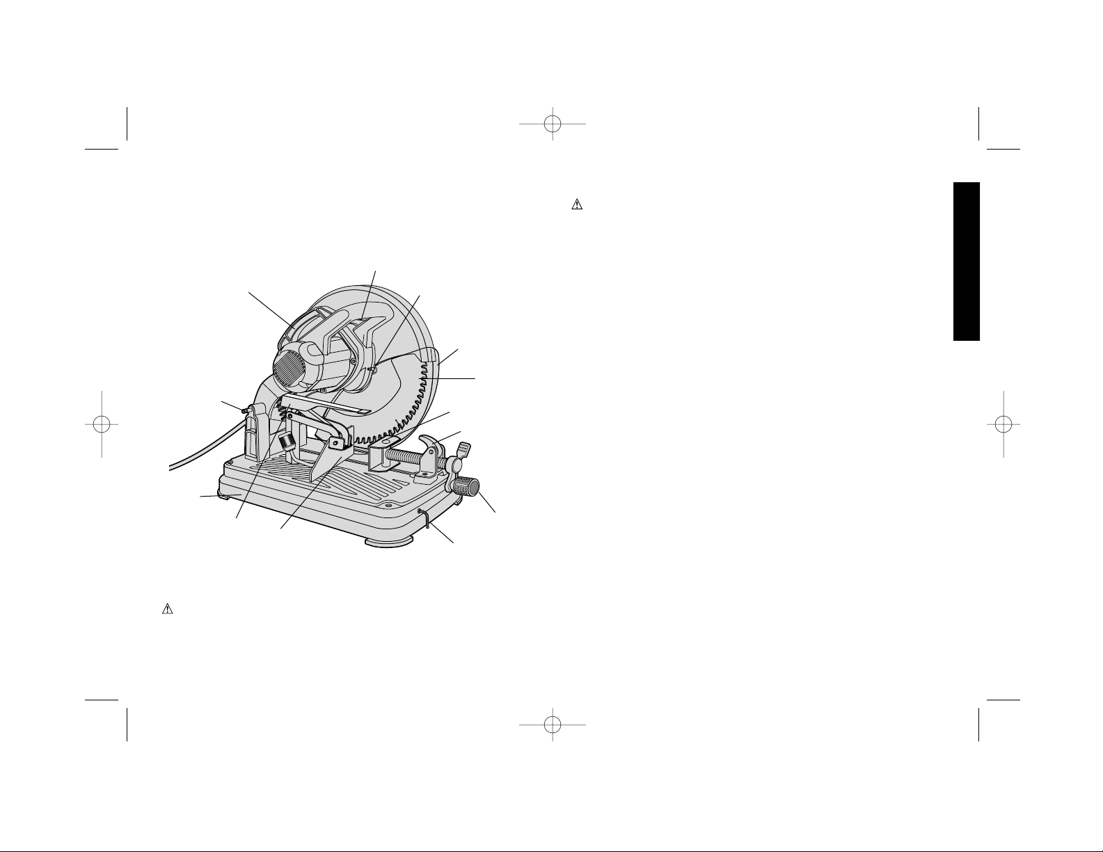
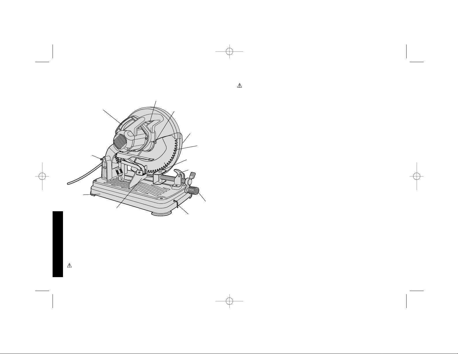
TRIGGER SWITCH
FENCE
VISE LEVER
CRANK
AUTO-
RETRACTING
GUARD
BLADE
VISE
CARRY
HANDLE
LOCK
DOWN PIN
BLADE LOCK LEVER
BASE
HEX
WRENCH
WARNING: FOR YOUR OWN SAFETY READ INSTRUCTION
MANUAL BEFORE OPERATING MULTI-CUTTER.
Important Safety Instructions
WARNING! Read and understand all instructions. Failure to
follow all instructions listed below may result in electric shock, fire
and/or serious personal injury.
Polarized Plugs
To reduce the risk of electric shock, this equipment has a polarized
plug (one blade is wider than the other). This plug will fit in a polarized
outlet, only one way. If the plug does not fit fully into the outlet,
reverse the plug. If it still does not fit, contact a qualified electrician
to install the proper outlet. Do not change the plug in any way. Units
rated for 220 volts will have a different style plug that will not fit the
outlet and is not polarized.
SAVE THESE INSTRUCTIONS
• KEEP GUARDS IN PLACE and in working order.
• REMOVE ADJUSTING KEYS AND WRENCHES. Form habit of
checking to see that keys and adjusting wrenches are removed from
tool before turning it on.
• KEEP WORK AREA CLEAN. Cluttered areas and benches invite
injuries.
• DON’T USE IN DANGEROUS ENVIRONMENT. Don’t use power
tools in damp or wet locations, or expose them to rain. Keep work
area well lighted.
• KEEP CHILDREN AWA Y.All visitors should be kept at a safe distance
from work area.
• MAKE WORKSHOP KID PROOF with padlocks, master switches, or
by removing starter keys.
• DON’T FORCE TOOL. It will do the job better and safer at the rate for
which it was designed.
• USE RIGHT TOOL. Don’t force tool or attachment to do a job for which
it was not designed.
• USE PROPER EXTENSION CORD. Make sure your extension cord is
in good condition. When using and extension cord, be sure
1
AUXILIARY
VERTICAL
CLAMP
392736-01,00,DW872 6/29/00 9:00 AM Page 1
Page 4

English
to use one heavy enough to carry the current your product will
draw. An undersized cord will cause a drop in line voltage resulting
in loss of power and overheating. The following table shows the
correct size to use depending on cord length and nameplate
ampere rating. If in doubt, use the next heavier gage. The smaller
the gage number, the heavier the cord.
Minimum Gage for Cord Sets
Volts Total Length of Cord in Feet
120V 0-25 26-50 51-100 101-150
240V 0-50 51-100 101-200 201-300
Ampere Rating
More Not more AWG
Than Than
0- 6 18 16 16 14
6 - 10 18 16 14 12
10- 12 16 16 14 12
12- 16 14 12 Not Recommended
•
WEAR PROPER APPAREL. Do not wear loose clothing, gloves,
neckties, rings, bracelets, or other jewelry which may get caught
in moving parts. Non-slip footwear is recommended. Wear
protective hair covering to contain long hair.
• ALWAYS USE SAFETY GLASSES. Also use face or dust mask if
cutting operation is dusty. Everyday eyeglasses only have impact
resistant lenses, they are not safety glasses.
• SECURE WORK. Use clamps, including supplied auxiliary vertical
clamp and/or a vise to hold work. It’s safer than using your hand.
• DON’T OVERREACH. Keep proper footing and balance at all times.
• MAINTAIN TOOLS WITH CARE. Keep tools sharp and clean for best
and safest performance. Follow instructions for lubricating and
changing accessories.
• DISCONNECT TOOLS before servicing; when changing accessories,
such as blades, bits, cutters, and the like.
• REDUCE THE RISK OF UNINTENTIONAL STARTING. Make sure
switch is in off position before plugging in.
• USE RECOMMENDED ACCESSORIES. Consult the instruction
manual for recommended accessories. The use of improper
accessories may cause risk of injury to persons.
• NEVER STAND ON TOOL. Serious injury could occur if the tool is
tipped over or if the cutting tool is unintentionally contacted.
• CHECK DAMAGED PARTS.Before further use of the tool, a guard or
other part that is damaged should be carefully checked to determine
that it will operate properly and perform its intended function — check
for alignment of moving parts, binding of moving parts, breakage of
parts, mounting, and any other conditions that may affect its operation.
A guard or other part that is damaged should be properly repaired or
replaced.
• NEVER LEAVE TOOL RUNNING UNATTENDED. TURN POWER
OFF. Don’t leave tool until it comes to a complete stop.
• REPLACEMENT PARTS. When servicing use only identical
replacement parts.
• TO REDUCE THE RISK OF ELECTRIC SHOCK, this equipment has
a polarized plug (one blade is wider than the other.) This plug will fit in
a polarized outlet only one way. If the plug does not fit, contact a
qualified electrician to install the proper outlet. DO NOT CHANGE THE
PLUG IN ANY WAY .
Additional Specific Safety Rules
• BE SURE THE BLADE BOLT IS TIGHTENED SECURELY
BEFORE CUTTING.
• Wear eye protection.
• Keep hands out of path of saw blade. Never cut a piece where
hand would be 6" (152 mm) or less from blade.
• Do not operate saw without guards in place.
• Do not perform any operation freehand.
• Never reach in back of saw blade.
• Turn off tool and wait for saw blade to stop before moving
workpiece or changing settings.
• Disconnect power before changing blade or servicing.
• No Load speed of this tool is 1300 rpm.
• Always position tool on a flat, stable surface before use.
2
392736-01,00,DW872 6/29/00 9:00 AM Page 2
Page 5

3
English
• Do not use cutting fluids with this electric tool. The fluids could ignite,
cause electrical shock, or chemically attack the plastic lower guard.
• Be aware of cutting chips and the material being cut. They may be
sharp and hot. Allow cut off parts to cool before handling
• Before using, inspect the blade for cracks or flaws. If a crack or flaw is
evident—discard the blade! The blade should also be inspected
whenever you think the tool or blade may have been dropped.
• Never start the tool with a person in line with the blade. This includes
the operator.
• In operation, avoid bouncing the blade or giving it rough treatment.
If this occurs, stop the tool and inspect the blade.
• Clean your tool periodically following the procedure in this manual.
• Do not remove blade guards.
• ALWA YS USE THE VISE OR SPECIAL FIXTURE TO CLAMP
WORK SECUREL Y. Other aids such as the supplied auxiliary vertical
clamp, spring, bar, or C-clamps may be appropriate for certain sizes
and shapes of workpiece. Use care in selecting and placing these
clamps and make a dry run before making a cut. The auxiliary vertical
clamp must be used when cutting on the upstroke of the blade See
Auxiliary Vertical Clamp section of this manual.
• NEVER CUT MAGNESIUM WITH THIS TOOL.
• Use tool in a well-ventilated area.
• Turn tool off before removing any pieces from the base.
• DO NOT CUT ELECTRICALLY LIVE MATERIAL.
• Use only genuine D
EWALT14” (355mm) carbide tipped metal cutting
blades. Never use abrasive cut off wheels or other type of saw blade.
• Do not cut concrete, stone, brick, tile or ceramic.
• Make sure the blade lock (Fig. 4) is released before switch is turned on.
• Keep hands and body away from rotating blade.
• Make sure blade is not contacting the work piece before the switch is
turned on.
• DO NOT CUT material LESS than 18 gauge (.0478”, 1.2 mm) in
thickness.
• DO NOT OPERATE THIS TOOL NEAR FLAMMABLE LIQUIDS,
GASES OR DUST. Sparks or hot chips from cutting or arcing motor
brushes may ignite combustible materials.
WARNING: Some dust created by power sanding, sawing,
grinding, drilling, and other construction activities contains chemicals
known to cause cancer, birth defects or other reproductive harm.
Some examples of these chemicals are:
• lead from lead-based paints,
• crystalline silica from bricks and cement and other masonry
products, and
• arsenic and chromium from chemically-treated lumber (CCA).
Your risk from these exposures varies, depending on how often you
do this type of work. To reduce your exposure to these chemicals:
work in a well ventilated area, and work with approved safety
equipment, such as those dust masks that are specially designed to
filter out microscopic particles.
Power Supply
Be sure your power supply agrees with the nameplate marking.
120 volts, “60 Hz” means alternating current (normal 120 volt, 60
Hz house current).
A voltage decrease of more than 10% will cause a loss of power and
overheating.
Cutting Capacity
The wide vise opening and high pivot point provide cutting capacity
for many large pieces. Use the cutting capacity chart to determine
total maximum size of cuts that can be made.
CAUTION: CERTAIN LARGE, CIRCULAR OR IRREGULARLY
SHAPED OBJECTS MAY REQUIRE ADDITIONAL HOLDING
MEANS IF THEY CANNOT BE HELD SECURELY IN THE VISE.
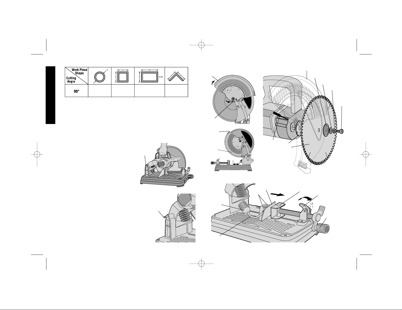
Maximum Cutting Capacity
NOTE: CAPACITY SHOWN ON CHART ASSUMES OPTIMUM FENCE
POSITION.
392736-01,00,DW872 6/29/00 9:00 AM Page 3
Page 6
4
English
Standard Equipment
1 14” (355mm) genuine DEWALT Metal Cutting Blade.
1 Blade Wrench in base holder.
1 Vise Attachment
1 Auxiliary vertical clamp
To Carry (Fig. 1)
Fold down unit to position where you
can carry the saw. Push in lock pin (A) to
lock arm down.
Unlocking (Fig. 2)
To unlock tool, depress carry handle
slightly and pull lock pin (A) out. Motor
arm will then pivot upward.
Installation of Blade
(Fig. 3 & 4)
1. UNPLUG UNIT FROM POWER SUPPL Y.
2. With motor arm in the up position, rotate
the lower guard (A) out of the way and
hold with one hand. (Shown in dotted
lines to show the rest of the detail)
3. With the same hand, depress the blade
lock lever (I) until it engages one of the
holes in the inner clamp washer (H). With
C
FIG. 5
B
A
FIG. 3
A
E
D
FIG. 4
G
H
F
A
I
C
B
FIG. 6
A
F
E
D
G
A
FIG. 2
B
A
FIG. 1
5-3/16” 4-3/4” 4-1/4 x 7” 5-9/16”
392736-01,00,DW872 6/29/00 9:00 AM Page 4
Page 7
5
English
FIG. 8
B
A
FIG. 9
FIG. 7
A
B
D
C
E
A
the hex wrench rotate the bolt cover (B) out of the way and loosen
the bolt (C) counterclockwise. Then remove the bolt (C), lock
washer (D), the flat washer (E) and the outer clamp washer (F).
4. Install blade (G) oriented as shown against the inner clamp
washer (H). Reassemble the outer clamp washer, flat washer,
lock washer and bolt hand tight.
5. With blade lock engaged, tighten the bolt securely with the hex
wrench.
6. Remove hex wrench then release lower guard and blade lock
lever.
7. Use same steps to remove the blade.
DO NOT MAKE ANY ADJUSTMENT WHILE TOOL IS PLUGGED
INTO POWER SUPPLY.
WARNING: VISUALLY CHECK BLADE FOR CRACKS OR
OTHER DAMAGE. VERIFY PROPER BLADE INSTALLATION
BEFORE USE. IF BLADE IS DAMAGED IN ANY WAY, HAVE IT
RECONDITIONED AT A QUALIFIED SAW BLADE SERVICE
SHOP.
WARNING: BE SURE THE BLADE BOLT IS TIGHTENED
SECURELY AND THE BOLT COVER IS COVERING THE BOLT
HEAD BEFORE CUTTING.
Auto Retracting Guard (Fig. 5)
This tool has an automatic retracting lower guard system. The blade
is exposed as it approaches the material and is covered in the up
position.
• When cutting very large pieces, it may be necessary to manually
assist the guard in retracting. To accomplish this, rotate the guard
(A) slightly by the lip (B), just enough to clear the workpiece and
release.
• Keep hands and other body parts away from rotating blade.
• Do not remove blade guard system.
• Keep guard system in good operating condition.
392736-01,00,DW872 6/29/00 9:00 AM Page 5
Page 8
6
A
FIG. 10
English
FIG. 11
A
B
C
FIG. 12
D
E
F
G
G
Vise Operation (Fig. 6)
The vise (A) has a quick travel feature. To release the vise when it is
clamped tightly, turn the crank (B) counterclockwise one or two times
to remove clamping pressure. Lift vise lever (C). Pull crank assembly
out as far as desired. Vise may be shoved into work without cranking.
Lower vise lever then tighten vise on work by using crank.
Fence Operation (Fig. 6)
The fence (D) requires no wrenches to operate. The quick release
clamp lever (E) unlocks and locks the fence. When the lever is
rotated fully forward, toward the vise, the fence is unlocked. The
fence can then be freely moved forward, backward or rotated to allow
for the best cutting position.
Pushing the lever fully to the rear locks the fence in position selected.
If the leg (G) of the lever is not horizontal (parallel to the base), the
fence is not locked. Lever will only lock fence when there is strong
resistance to rotate it backwards, which engages the cam action. If
resistance is light, adjust clamping force by slightly tightening the two
bolts (F) holding the fence to the base. Test by clamping the
workpiece with the vise. Adjust as needed to assure that the fence
does not move and the workpiece is securely clamped.
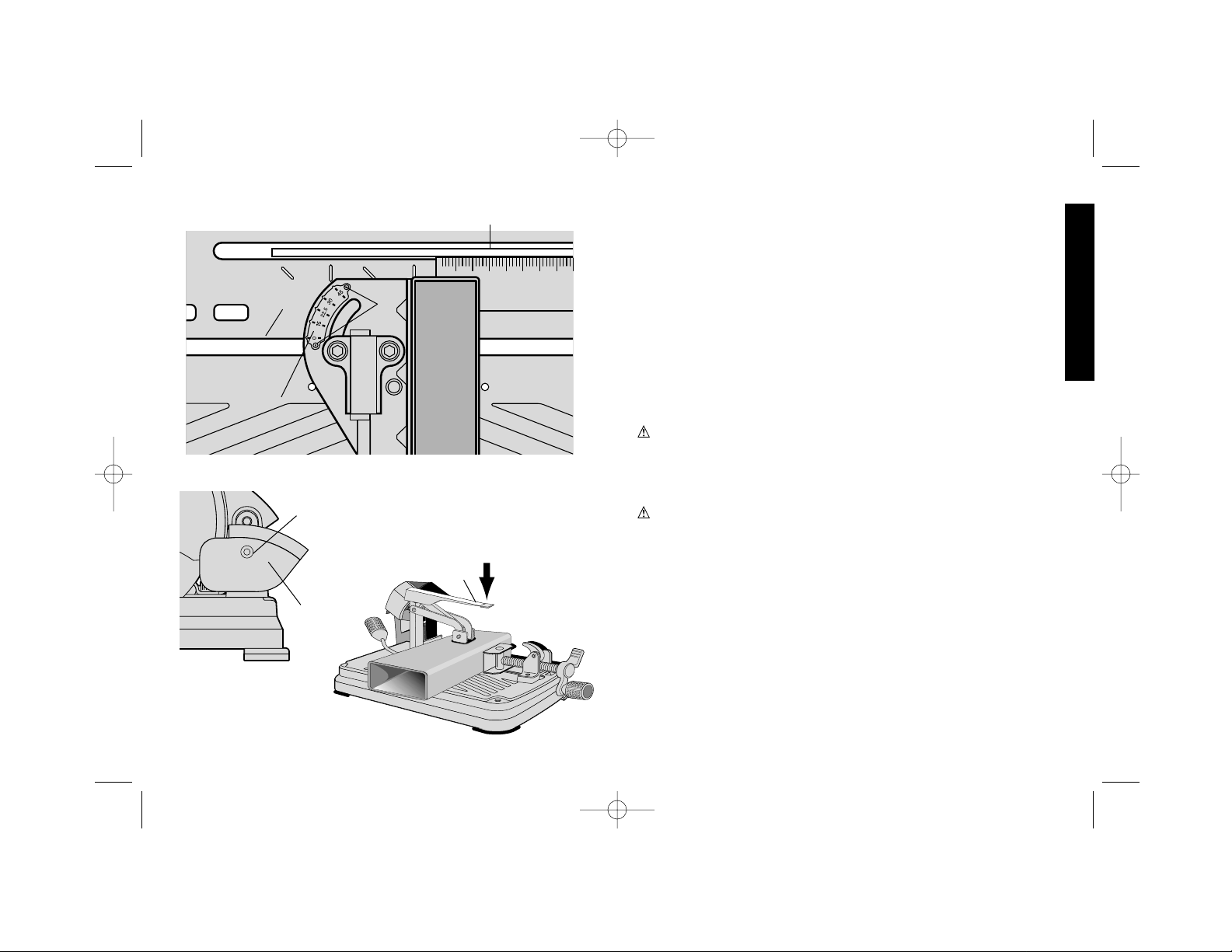
Fence Angle Adjustment (Fig. 7)
To make angle cuts, unlock and rotate the fence until the desired
angle on the angle plate (A) lines up with the edge of the slot (B) in
the base, then re-lock the fence.
The angle plate (A) is attached to the fence by screws (E) and is
preset at the factory. If it becomes necessary to readjust the angle
plate for accuracy, perform the following steps.
1. DISCONNECT THE POWER SUPPLY.
2. Unlock the fence and lock the arm in the down position so the
392736-01,00,DW872 6/29/00 9:00 AM Page 6
Page 9

7
English
A
FIG. 13
FIG. 14
10-1/8"
(257 MM)
FIG. 15
17-3/8"
(441 MM)
blade extends into the base.
3. Place a square (C) against the blade (D), adjust the fence against
the square and then re-lock the fence.
4. Unlock and raise the arm.
5. Loosen the two angle plate screws (E). Align the 0˚ pointer with
the edge of the slot (B) and retighten the screws.
Chip Deflector Adjustment (Fig. 8)
To aim chips away from surrounding area or into a collection bin,
loosen the screw (A), adjust the chip deflector (B) angle and retighten
the screw.
Auxiliary Vertical Clamp (Fig. 9)
The auxiliary vertical clamp (A) MUST be used with the vise when
cutting wide or irregular shaped materials, when making angle cuts,
and when the fence is in the rear positions where the upstroke of the
blade tends to pull the workpiece up from the vise.
To use the clamp, insert it in one of the holes (Fig. 11,G) in the base
until the clamp rests on the workpiece. Press the lever down as
shown in Fig. 9 to lock the workpiece in place. Lift the lever to release
the clamp.
NOTE: When clamping thin stock, a shim of suitable thickness may
be required under the clamp pad.
WARNING: Failure to use vertical clamping when cutting on the
upstroke of the blade may result in serious damage to the tool and
possible personal injury.
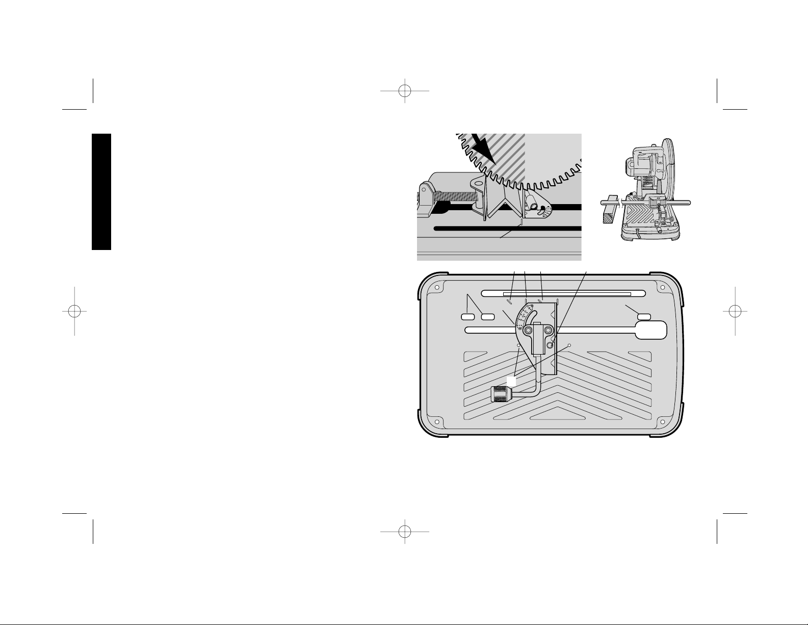
Material Positioning and Clamping Tips
(Fig. 10, 11, 12)
• TURN OFF AND UNPLUG TOOL BEFORE MAKING ANY
ADJUSTMENT TO THE SAW OR REPOSITIONING A WORKPIECE.
• In general, position the workpiece so it will be cut on the down-
stroke of the blade. (Shaded area) Slot (A) indicates the best fence
position for general cutting at 90˚.
• Slots (A) and (B) indicate the best fence positions for general
cutting at 90˚ and 45˚. Slots (C) and (D) indicate the same for larger
pieces. (Fig. 11 )
• When the fence is lined up with a slot in the base, the spring loaded
pin (E) will drop into the corresponding hole (F) in the base to
further secure the fence position. To move fence to another
position, pull up the pin.
• The fence can also be used in other angles and positions, as
needed.
• Long workpieces must be supported by a block so it will be level
with the saw table The cut off piece should be free to fall downward
to avoid blade binding.(Fig. 12)
• ALWAYS CLAMP THE WORKPIECE SECURELY, NO EXCEP-
TIONS.
• Always clamp the workpiece with the vise and auxiliary vertical
clamp as described.
• The auxiliary vertical clamp or other clamping aids such as spring,
bar or C-clamps will compliment the vise for holding certain sizes
and shapes of work pieces. Use care in selecting and placing these
392736-01,00,DW872 6/29/00 9:00 AM Page 7
Page 10

English
8
.3"
(8 MM)
C
FIG. 16
A
B
D
FIG. 17
clamps. Make a dry run before making the cut.
Switch (Fig. 13)
To start the tool, depress the trigger switch (A). To turn the tool off,
release the trigger switch. Keep hands and material from blade until
it has coasted to a stop.
CAUTION: MAKE SURE THE BLADE IS NOT TOUCHING THE
WORKPIECE WHEN THE TOOL IS STARTED.
Cutting Process Checklist
1. BEFORE STARTING THE TOOL, MAKE SURE:
• Tool is securely mounted on a stable surface.
• Blade is mounted correctly and blade bolt is tight.
• Fence is set properly and locked in place.
• Workpiece is held firmly in the vise and vertically clamped as
described.
• Chip deflector is properly adjusted.
2. Start the motor and allow the blade to come up to full speed.
3. Pull the handle down slowly to make initial contact with the
workpiece. Once contact is made, increase feed rate, allowing
the blade to do the work. Slow down just before the cut is
complete.
4. After the cut is complete, turn the tool off and keep hands away
until blade has stopped spinning.
CAUTION: When cutting small pieces, (less than one inch) the
scrap may be thrown toward the rear of the unit.
Good Care/Cutting Practices
1. The blade teeth are made of carbide material which is very hard,
yet brittle. Vibration increases side loads that could cause chipping
of teeth or cracking of the blade. Here are some important tips that
will help prolong the life of the blade and the tool:
• Position the workpiece as much as possible under the downstroke of the blade (Figure 10). Material must be firmly clamped
and supported to reduce vibration. NO EXCEPTIONS.
• Never perform cuts on small workpieces bundled together.
• Position the workpiece so that the blade is cutting through the
smallest cross section.
• Avoid cutting large, flat, horizontal surfaces where possible. The
lowest number of blade teeth contacting the workpiece during the
cut will produce the least amount of heat and increase blade life.
2. The following signs indicate that the blade is worn and should be
resharpened or replaced:
• Poor cutting performance.
• More sparks than chips created during a cut.
• The ringing sound of the blade increases.
Procedure For Permanent Mounting
(Fig. 14)
(Recommended when multiple cuts will be made at the same
location)
1. Drill four holes 5/16" through the work surface. (Figure 14)
392736-01,00,DW872 6/29/00 9:00 AM Page 8
Page 11

9
English
2. Insert 1/4-20 screws down through the holes in the base and
through holes in mounting surface. The approximate length of
the screws should be the thickness of the mounting surface plus
4 inches.
CRADLE MOUNTING
1. Cut two boards approximately 20" long x 2" high x 4" wide.
2. Place tool at desired work location.
3. Place boards tightly along side, and attach to work surface,
(Figure 15).
Maintenance
Motor Brush Inspection and Replacement
(Fig. 16)
BE SURE TOOL IS UNPLUGGED BEFORE INSPECTING
BRUSHES. Brushes should be regularly inspected for wear. To
inspect brushes, unscrew the two end cap screws (A) and remove
end cap (B). To remove each brush, (C) first unplug the shunt wire
terminal connection. Then carefully back the brush spring (D) out of
the brush box and remove brush. Brushes should slide freely in brush
box. If brushes are worn down to .3” (8mm) (see Figure 17) they
should be replaced. To reinstall each brush carefully back the spring
out of the brush box, insert the brush and return the spring making
sure it is pressing on the brush and not touching the brush box.
Reconnect shunt wire terminal, then replace the end cap and two
screws.
Cleaning
Blowing dust and grit out of the main housing and chip deflector by
means of an air hose is recommended and should be done as often
as dirt is seen collecting in and around the air vents.
Accessories
Blades are available at extra cost from your local dealer or
authorized service center. If you need assistance in locating this
accessory for your tool, contact:
DEWALT Industrial Tool Co., 701 East Joppa Road, Baltimore, MD
21286
CAUTION: The use of any other accessory not recommended
for use with this tool could be hazardous.
Important
To assure product SAFETY and RELIABILITY, repairs, maintenance
and adjustment other than those discussed in this manual should be
performed by authorized service centers or other qualified service
organizations, always using identical replacement parts.
Lubrication
Closed-type, grease-sealed ball bearings are used throughout. These
bearings have sufficient lubrication packed in them at the factory to last
the life of the tool.
Gears should be relubricated every 60 to 90 days, depending upon
use. This lubrication should only be attempted by experienced power
tool repair persons like the mechanics at D
EWAL T service centers. The
gear case should be wiped clean and 2 oz. (60 grams) of D
EWALT
Lubricant Part No. 790206 (6 oz. tube) placed in the gear case.
Full Warranty
D
EWALT heavy duty industrial tools are warranted for one year from
date of purchase. We will repair, without charge, any defects due to
faulty materials or workmanship. For warranty repair information, call
1-800-4-D
EWALT. This warranty does not apply to accessories or
damage caused where repairs have been made or attempted by
others. This warranty gives you specific legal rights and you may have
other rights which vary in certain states or provinces.
In addition to the warranty, D
EWALT tools are covered by our:
30 DAY NO RISK SATISFACTION GUARANTEE
If you are not completely satisfied with the performance of your
392736-01,00,DW872 6/29/00 9:00 AM Page 9
Page 12

English
Trouble Shooting Guide
TROUBLE! TOOL WILL NOT START
WHAT’S WRONG? WHAT TO DO…
1. Tool not plugged in. 1.Plug in saw.
2. Fuse blown or circuit breaker tripped. 2.Replace fuse or reset circuit breaker.
3. Cord damaged. 3.Have cord replaced by authorized service center.
4. Brushes worn out. 4.Have brushes replaced by authorized service center.
TROUBLE! TOOL MAKES UNSATISFACTORY CUTS
WHAT’S WRONG? WHAT TO DO…
1. Dull blade. 1.Replace or sharpen blade. See Good Care/Cutting Practices pages 7 and 8.
2. Workpiece incorrectly placed or clamped. 2.Firmly clamp and support workpiece. See Material Positioning and Clamping page 7.
TROUBLE! BLADE DOES NOT COME UP TO SPEED
WHAT’S WRONG? WHAT TO DO…
1. Extension cord too light or too long. 1.Replace with adequate size cord. See chart on page 2.
2. Low voltage. 2.Contact your electric company.
3. Low generator voltage. 3.Check generator output voltage. Reduce number of tools powered by the generator.
TROUBLE! TOOL VIBRATES EXCESSIVELY DURING CUT
WHAT’S WRONG? WHAT TO DO…
1. Tool not mounted securely to stand or work bench. 1.Tighten all mounting hardware. See page 8, Procedures for Permanent Mounting.
2. Damaged saw blade. 2.Replace blade.
3. Workpiece not clamped properly. 3.Refer to Material Positioning and Clamping page 7, and Good Care and Cutting
Practices, pages 7 and 8.
TROUBLE! DOES NOT MAKE ACCURATE CUTS
WHAT’S WRONG? WHAT TO DO…
1. Fence not adjusted correctly. 1.Check and adjust. See Fence Operation on page 5.
2. Blade is not square to fence. 2.Check and adjust. See Fence Angle Adjustment on page 6.
3. Excessive force used to make cut. 3.Reduce cutting force, let the blade do the work.
4. Work piece moving. 4.Clamp workpiece securely. See Material Positioning and Clamping page 7. Make sure
material is laying flat against the base.
TROUBLE! CANNOT MOVE ARM
WHAT’S WRONG? WHAT TO DO…
1. Auto-retracting blade guard will not move. 1.Check for damaged parts. Check for excessive chips in guard. Replace or repair as needed.
2. Lock down pin is engaged. 2.Push down slightly on the arm, pull lock down pin out. Raise arm. See page 3.
TROUBLE! MATERIAL MOVES DURING CUT
WHAT’S WRONG? WHAT TO DO…
1. Fence slipping or workpiece incorrectly placed or clamped. 1.See Material Positioning and Clamping, page 7.
2. Vise too loose 2.Tighten vise clamping. Use auxiliary vertical clamp. See Auxiliary Vertical Clamp, page 7.
3. Excessive cutting force. 3.Reduce cutting force.
10
392736-01,00,DW872 6/29/00 9:00 AM Page 10
Page 13

Importantes consignes de sécurité
AVERTISSEMENT! Bien lire et comprendre toutes les consignes.
Le non-respect, même partiel, des instructions ci-dessous entraînera
un risque d’électrocution, d’incendie et/ou de blessures graves.
Fiches polarisées
Pour réduire les risques d’électrocution, cet équipement a une fiche
polarisée (une lame plus large que l’autre). Cette fiche s’insère dans
une prise polarisée, dans un sens seulement. Si elle ne s’insère pas
bien dans la prise, il suffit de la retourner. Si elle persiste à ne pas
entrer, appeler un électricien qualifié pour installer la prise qui
convient. Ne pas essayer de modifier la fiche en aucune façon. Les
appareils de 220 volts ont une prise de type différent qui ne peut
pénétrer dans la même prise et qui n’est pas polarisée.
CONSERVER CES MESURES
· GARDER LES CARTERS DE PROTECTION EN PLACE et en bon
état.
· ENLEVER LE DISPOSITIF DE RÉGLAGE ET LA CLÉ. Prendre
l’habitude de vérifier si la clé et le dispositif de réglage sont enlevés
de l’outil avant de faire fonctionner celui-ci.
· GARDER LA ZONE DE TRAVAIL PROPRE. Les espaces et les
établis encombrés occasionnent des blessures.
· NE PAS UTILISER DANS UN MILIEU DANGEREUX. Ne pas utiliser
d'outils électriques dans des lieux humides ou mouillés et ne pas les
exposer à la pluie. L’espace de travail doit être bien éclairé.
· ÉLOIGNER LES ENFANTS. Tous les visiteurs doivent rester à une
distance sécuritaire de la zone de travail.
· S’ASSURER QUE L’ATELIER EST SÉCURITAIRE POUR LES
ENFANTS en posant des cadenas ou enlevant les clés de mise en
marche.
· NE P AS FORCER UN OUTIL.L ’outil fonctionne mieux et de façon plus
sûre à la vitesse pour laquelle il a été conçu.
11
Français
INTERRUPTEUR À GACHETTE
GUIDE
LEVIER DE
L’ÉTAU
MANIVELLE
CARTER DE
PROTECTION
AUTORÉTRAC-
TABLE
LAME
ÉTAU
POIGNÉE DE
TRANSPORT
GOUPILLE
DE
VERROUIL
LAGE
LEVIER DE
VERROUILLAGE DE
LA LAME
BASE
CLÉ
HEXAGONALE
POUR TOUT RENSEIGNEMENT SUPPLÉMENT AIRE SUR CET OUTIL OU
TOUT AUTRE OUTIL DEWALT, COMPOSER SANS FRAIS LE NUMÉRO :
1-800-4-DEWALT (1-800-433-9258)
AVERTISSEMENT : POUR LA SÉCURITÉ PERSONNELLE,
LIRE LE MANUEL D’INSTRUCTIONS AVANT DE FAIRE
FONCTIONNER L’OUTIL DE COUPE MULTIPLE.
392736-01,00,DW872 6/29/00 9:00 AM Page 11
Page 14

12
· DÉBRANCHER LES OUTILS avant de les réparer, de changer les
accessoires comme les lames, les mèches, les forets, etc.
· RÉDUIRE LE RISQUE DE DÉMARRAGE ACCIDENTEL. Avant de
brancher l’outil, s’assurer que l’interrupteur est à la position d'arrêt.
· UTILISER LES ACCESSOIRES RECOMMANDÉS. Consulter le
manuel d’instructions pour les accessoires recommandés. L’usage de
mauvais accessoires risque de causer des blessures.
· NE JAMAIS SE TENIR DEBOUT SUR UN OUTIL. De graves
blessures peuvent se produire si l’outil bascule ou s’il est mis en
marche accidentellement.
· VÉRIFIER LES PIÈCES ENDOMMAGÉES. Avant d’utiliser l’outil, il
faut soigneusement vérifier tout carter de protection, ou autre pièce
endommagée pour s’assurer qu’il fonctionne bien et remplit son rôle.
Vérifier l’alignement et la liberté de mouvement des pièces mobiles,
l’intégrité des pièces, le montage et toute autre condition qui peut
altérer le fonctionnement. Si un carter de protection ou une autre pièce
est endommagé, il faut le réparer ou le remplacer.
· NE JAMAIS LAISSER UN OUTIL EN MARCHE SANS
SURVEILLANCE. IL FAUT L’ÉTEINDRE. Ne pas quitter l’outil avant
qu’il ne soit complètement arrêté.
· PIÈCES DE RECHANGE. N’utiliser que des pièces de rechange
identiques.
· POUR RÉDUIRE LE RISQUE D’ÉLECTROCUTION, cet équipement
a une fiche polarisée (une lame plus large que l’autre). Cette fiche
s’insère dans une prise polarisée, dans un sens seulement. Si elle ne
s’insère pas bien dans la prise, appeler un électricien qualifié pour
installer la prise qui convient. NE PAS ESSAYER DE MODIFIER LA
FICHE DE QUELQUE MANIÈRE QUE CE SOIT.
Autres règles de sécurité
· S’ASSURER QUE LE BOULON DE LA LAME EST BIEN SERRÉ
AVANT DE COUPER.
· Toujours porter des lunettes protectrices.
· Garder les mains hors de la trajectoire de la lame. Ne jamais couper
une pièce si la main doit être à moins de 6 po (152 mm) de la lame.
Français
· UTILISER L’OUTIL ADÉQUAT. Ne pas forcer l’outil ou l’accessoire
pour un travail auquel il n’est pas destiné.
· UTILISER LA RALLONGE APPROPRIÉE. S’assurer que la rallonge
est en bon état et du calibre approprié pour le courant utilisé par le
produit. Un cordon de rallonge trop petit produit une chute de tension,
une perte de puissance et une surchauffe. Le tableau suivant indique
le calibre correct à utiliser en fonction de la longueur de la rallonge et
de l’intensité indiquée sur la plaque signalétique. En cas de doute,
utiliser le calibre supérieur suivant. Plus le chiffre du calibre est petit,
plus le fil est gros.
Calibre minimal des cordons de rallonge
Longueur totale du cordon
25 ft. 50 ft. 75 ft. 100 ft. 125 ft. 150 ft. 175 ft.
7.6 m 15.2 m 22.9 m 30.5 m 38.1 m 45.7 m 53.3 m
Intensité
18 AWG 18 AWG 16 AWG 16 AWG 14 AWG 14 AWG 12 AWG
· PORTER DES VÊTEMENTS APPROPRIÉS. Ne pas porter de
vêtements lâches, de gants, de cravates ou de bijoux qui risquent de
se prendre dans les pièces mobiles. Il est recommandé de porter des
chaussures antidérapantes et de couvrir les cheveux longs.
· PORTER DES LUNETTES PROTECTRICES. Utiliser aussi un
masque antipoussière si les conditions de travail l’exigent. Les lunettes
ordinaires ont seulement des verres qui résistent aux chocs; ce ne sont
pas des lunettes de protection.
· FIXER L’OUVRAGE. Utiliser des serre-joint ou un étau pour fixer
l’ouvrage. C'est plus sûr que d’utiliser les mains et libère ces dernières
pour faire fonctionner l’outil.
· NE PAS SE DÉSÉQUILIBRER, bien placer les pieds et conserver
son équilibre en tout temps.
· ENTRETENIR LES OUTILS AVEC SOIN. Garder les outils bien
aiguisés et propres pour un meilleur rendement et une plus grande
sécurité. Suivre les instructions de lubrification et de changement des
accessoires,
392736-01,00,DW872 6/29/00 9:00 AM Page 12
Page 15

· NE PAS COUPER UN MATÉRIAU SOUS TENSION.
· N’utiliser que les lames de coupe du métal au carbure de 14 po (355
mm) de DeWALT . Ne jamais utiliser de disques de coupe abrasifs ni
d’autre type de lame de scie.
· Ne pas couper de béton, de pierre, de brique de carreaux ou de
céramique.
· S’assurer que le verrouillage de la lame (Fig. 4) est dégagé avant de
mettre l’interrupteur sur Marche.
· Garder les mains et le corps loin de la lame rotative.
· S’assurer que la lame ne touche pas la pièce de travail avant que l’on
ait appuyé sur l’interrupteur de mise en marche.
· NE PAS COUPER DE MATÉRIAU d’une épaisseur INFÉRIEURE au
calibre 18 (0,0478 po, 1,2 mm).
· NE PAS FAIRE FONCTIONNER CET OUTIL DANS LE VOISINAGE
DE LIQUIDES, DE GAZ OU DE POUSSIÈRES INFLAMMABLES. Les
étincelles ou des copeaux brûlants provenant de la coupe ou de
l’amorçage d’arc des balais du moteur risquent d’enflammer les
matériaux combustibles.
AVERTISSEMENT : Certains outils, tels que les sableuses
électriques, les scies, les meules, les perceuses ou certains autres
outils de construction, peuvent soulever de la poussière contenant des
produits chimiques susceptibles d’entraîner le cancer, des
malformations congénitales ou pouvant être nocifs pour le système
reproductif. Parmi ces produits chimiques, on retrouve :
• le plomb dans les peintures à base de plomb;
• la silice cristalline dans les briques et le ciment et autres produits de
maçonnerie;
• l’arsenic et le chrome dans le bois de sciage ayant subi un
traitement chimique (CCA).
Le risque associé à de telles expositions peut varier selon la fréquence
avec laquelle on effectue ces travaux. Pour réduire l’exposition à de
tels produits, il faut travailler dans un endroit bien ventilé et utiliser
l’équipement de sécurité approprié tel un masque anti-poussières
spécialement conçu pour filtrer les particules microscopiques.
13
Français
· Ne pas utiliser la scie sans carter de protection en place.
· Ne jamais exécuter de tâche à main levée.
· Ne jamais tendre la main à l’arrière de la lame de scie.
· Toujours arrêter l’outil et attendre que la lame soit immobilisée avant
de déplacer la pièce ou de modifier les réglages.
· Débrancher l’outil avant de changer la lame ou d’effectuer l’entretien.
· La vitesse à vide de cet outil est de 1 300 tr/min.
· Toujours placer l’outil sur une surface plate et stable avant de l’utiliser.
· Ne pas utiliser de liquides de coupe avec cet outil, car ils risquent de
s’enflammer ou de causer une électrocution.
· Faire attention aux copeaux de coupe et au matériel coupé. Ils peuvent
être tranchants et chauds. Laisser les morceaux coupés refroidir avant
de les toucher.
· Avant l’utilisation, inspecter la lame pour voir si elle est fissurée ou si
elle présente des défauts. Si c’est le cas, la jeter. Toujours vérifier la
lame quand on a des raisons de croire que celle-ci ou l’outil est
tombé(e).
· Ne jamais mettre l’outil en marche quand il y a une personne dans
l’axe de la lame. Ceci s’applique aussi à l’utilisateur.
· Pendant le fonctionnement, éviter de faire rebondir la lame ou de la
manipuler brutalement. Si cela se produit, arrêter l’outil et vérifier.
· Nettoyer périodiquement l’outil de coupe multiple en suivant la
procédure indiquée dans ce manuel.
· Ne pas enlever les carters de protection de la lame.
· TOUJOURS UTILISER L’ÉTAU OU UN DISPOSITIF DE FIXATION
APPROPRIÉ POUR BIEN TENIR LA PIÈCE DE TRAVAIL. Les autres
accessoires fournis (serre-joint, ressort, barre ou serre-joint en C)
peuvent être utiles pour certaines dimensions et formes de pièce de
travail. Faire bien attention dans le choix et la pose de ces serre-joint
et faire un essai avant de couper. Le serre-joint auxiliaire doit être
utilisé pour la coupe dans le sens de la rotation de la lame. Lire la
section se rapportant au serre-joint auxiliaire.
· NE JAMAIS COUPER DE MAGNÉSIUM AVEC CET OUTIL.
· Utiliser l’outil dans une zone bien aérée.
· Éteindre l’outil avant d’enlever une pièce de la base.
392736-01,00,DW872 6/29/00 9:00 AM Page 13
Page 16

14
Transport (Fig. 1)
Replier l’appareil à la position qui permet de transporter la scie.
Enfoncer la goupille de verrouillage (A) pour verrouiller le bras.
Déverrouillage (Fig. 2)
Pour déverrouiller l’outil, appuyer légèrement sur la poignée de
transport et tirer la goupille de verrouillage (A). Le bras du moteur
pivote alors vers le haut.
Installation de la lame (Fig. 3 et 4)
1. DÉBRANCHER L’APPAREIL DE LA PRISE ÉLECTRIQUE.
2. Le bras du moteur étant en position relevée, faire tourner le
carter inférieur (A) pour le mettre hors du chemin et le retenir
d’une main (montré en pointillé pour illustrer les détails).
3. Avec la même main, appuyer sur le levier de verrouillage de la
lame (I) jusqu’à ce qu’il s’engage dans l’un des trous de la
rondelle (H) du serre-joint interne. Avec la clé hexagonale, faire
tourner le chapeau du boulon (B) pour le sortir et desserrer le
boulon (C) dans le sens antihoraire. Ensuite, enlever le boulon
(C), la rondelle (D), la rondelle plate (E) et la rondelle (F) du
serre-joint externe.
4. Installer la lame (G) en l’orientant tel qu’illustré sur le dispositif
d’entraînement positif de la rondelle ((H) du serre-joint interne.
Remonter la rondelle du serre-joint extérieur, la rondelle-frein et
Français
Alimentation electrique
S’assurer que l’alimentation concorde avec les indications sur la
plaque signalétique, « 120 volts, 60 Hz » décrit un courant alternatif
(courant domestique normal de120 volts, 60 Hz).
Une baisse de tension de plus de 10 % provoquera une perte de
puissance et une surchauffe.
Capacité de coupe
L’ouverture de l’étau et le point de pivot élevé permettent de couper
de grandes pièces. Utiliser le tableau de capacité de coupe pour
déterminer la dimension de coupe maximale.
MISE EN GARDE : CERTAINS OBJETS DE GRANDE
DIMENSION, DE FORME CIRCULAIRE OU IRRÉGULIÈRE,
PEUVENT EXIGER UNE FIXATION SUPPLÉMENTAIRE S’ILS NE
PEUVENT ÊTRE RETENUS DANS L’ÉTAU DE FAÇON
SÉCURITAIRE.
CAPACITÉ DE COUPE MAXIMALE
NOTE : LA CAPACITÉ INDIQUÉE SUR LE TABLEAU SUPPOSE
UNE POSITION OPTIMALE DU GUIDE.
Équipement standard
1authentique lame de coupe pour le métal de 14 po (355 mm)
DeWALT.
1clé de lame dans la retenue de la base
1fixation de l’étau
1serre-joint auxiliaire
FIG. 1
A
A
FIG. 2
134, 9 mm
5-3/16 po
120, 6 mm
4-3/4 po
107, 9 x 177, 8
4-1/4 x 7 po
141, 2 mm
5-9/16 po
392736-01,00,DW872 6/29/00 9:00 AM Page 14
Page 17

AVERTISSEMENT : S’ASSURER QUE LE BOULON DE LA
LAME EST BIEN SERRÉ ET QUE LE CHAPEAU DU BOULON EST
BIEN EN PLACE SUR LE BOULON AVANT DE COUPER.
Carter autorétractable (Fig. 5)
Cet outil comporte un carter à rétraction automatique. La lame est
exposée quand elle approche du matériau et est recouverte à la
position relevée.
· Quand on coupe de très grosses pièces, il peut être nécessaire
d’aider la rétraction du carter de la main. Pour cela, faire tourner
légèrement le carter (A) avec le rebord (B), il suffit de dégager la
pièce de travail et de la libérer.
· Garder la main et les autres parties du corps loin de la lame
rotative.
· Ne pas enlever le système de carter de protection de la lame.
· Garder le système de carter de protection en bon état de marche.
Fonctionnement de l’étau (Fig. 6)
L’étau (A) a un dispositif de déplacement rapide. Pour le desserrer,
faire tourner la manivelle (B) dans le sens antihoraire une ou deux
fois pour libérer la pression. Lever le levier de l’étau (C). Sortir la
manivelle à la distance désirée. L’étau peut être installé sur la pièce
15
Français
le boulon et serrer à la main.
5. Le verrouillage de la lame étant engagé, bien serrer le boulon
avec la clé hexagonale.
6. Enlever la clé et relâcher le levier inférieur et le levier de
verrouillage de la lame.
7. Suivre les mêmes étapes pour enlever la lame.
NE PAS FAIRE DE RÉGLAGE QUAND L’OUTIL EST BRANCHÉ.
AVERTISSEMENT : VÉRIFIER VISUELLEMENT SI LA LAME
EST FISSURÉE OU ENDOMMAGÉE, VÉRIFIER QUE LA LAME
EST BIEN INSTALLÉE AVANT DE L’UTILISER. SI LA LAME EST
ENDOMMAGÉE, LA FAIRE REMETTRE À NEUF PAR UN ATELIER
D’ENTRETIEN DE LAMES DE SCIE QUALIFIÉ.
C
B
FIG. 6
A
F
E
D
E
C
FIG. 5
B
A
FIG. 3
A
E
D
FIG. 4
G
H
F
A
I
B
392736-01,00,DW872 6/29/00 9:00 AM Page 15
Page 18

16
Réglage de l’angle du guide (Fig. 7)
Pour faire des coupes angulaires, déverrouiller le guide et le faire
tourner à l’angle désiré sur la plaque graduée (A) jusqu’à ce qu’elle
soit alignée avec le bord de la fente (B) dans la base, reverrouiller
ensuite le guide.
La plaque angulaire (A) est fixée au guide avec des vis (E) et
préréglée en usine. S’il faut régler de nouveau la plaque angulaire
pour plus de précision, suivre les étapes suivantes :
1. Débrancher l’appareil.
2. Déverrouiller le guide et verrouiller le bras en position basse de
façon que la lame dépasse de la base.
3. Placer un carré (C) contre la lame (D), régler le guide contre le
carré et verrouiller de nouveau le guide.
4. Déverrouiller et relever le bras.
5. Desserrer les deux vis (E) de la plaque angulaire. Aligner l’index
0° sur le bord de la fente (B) et resserrer les vis.
Français
de travail sans manœuvre de la manivelle. Baisser le levier de l'étau
et serrer ce dernier sur la pièce de travail avec la manivelle.
Fonctionnement du guide (Fig. 6)
Le fonctionnement du guide (D) ne demande aucune clé. Le
dégagement rapide du levier de serre-joint (E) déverrouille et
verrouille le guide. Quand on fait tourner le levier à fond vers l’avant,
le guide est déverrouillé. Il peut être déplacé librement vers l’avant,
vers l’arrière, ou être tourné pour obtenir la meilleure position de
coupe.
En poussant le levier à fond vers l’arrière, on verrouille le guide à la
position sélectionnée. Si la patte (G) du levier n’est pas horizontale
(parallèle à la base), le guide n’est pas verrouillé. Le levier ne
verrouille le guide que quand il y a une forte résistance qui le fait
tourner vers l’arrière, qui déclenche le mouvement de la came. Si la
résistance est faible, régler la force de serrage en serrant légèrement
les deux boulons (F) retenant le guide à la base. Faire un essai en
serrant la pièce de travail avec l’étau. Régler selon les besoins pour
s’assurer que le guide ne se déplace pas et que la pièce de travail
est bien serrée.
FIG. 7
A
B
D
C
E
FIG. 8
B
A
FIG. 9
A
392736-01,00,DW872 6/29/00 9:00 AM Page 16
Page 19

17
Français
Réglage du déflecteur de copeaux (Fig.
8)
Pour éjecter les copeaux de la zone avoisinante ou dans un bac de
récupération, desserrer la vis (A), régler l’angle du déflecteur de
copeaux (B) et resserrer la vis.
Serre-joint auxiliaire (Fig. 9)
Le serre-joint auxiliaire (A) DOIT être utilisé quand on coupe des
matériaux de grande dimension ou de forme irrégulière, quand on fait
des coupes angulaires et que le guide est à la position arrière quand
les courses montantes de la lame ont tendance à tirer la pièce de
travail hors de l’étau.
Pour utiliser le serre-joint, l’insérer dans l’un des trous (Fig. 11, G)
de la base jusqu’à ce qu’il appuie contre la pièce de travail. Abaisser
le levier comme le montre la Figure 9 pour verrouiller la pièce de
travail en place. Relever le levier pour déclencher le serre-joint.
NOTE : Pour effectuer le serrage d’un matériau mince, il peut être
nécessaire de placer une cale d’épaisseur adéquate sous le serrejoint.
AVERTISSEMENT :Si on n’utilise pas le serre-joint auxiliaire pour
couper dans le sens de rotation de la lame, l’outil peut subir des
dommages graves et l’utilisateur peut se blesser.
Conseils pour la mise en place du
matériau et le serrage(Fig. 10, 11, 12)
· ÉTEINDRE ET DÉBRANCHER L’OUTIL AVANT DE RÉGLER
LA SCIE OU DE REPOSITIONNER LA PIÈCE DE TRAVAIL.
· En général, il faut placer la pièce de travail de façon que la
coupe se fasse sur la course descendante de la lame (zone
ombrée). La fente A indique la meilleure position du guide pour la
coupe générale à 90°.
· Les fentes (A) et (B) indiquent les meilleures positions du guide
pour la coupe générale à 90° et à 45°. Les fentes (C) et (D)
indiquent la même chose pour les pièces plus grandes (Fig. 11 ).
A
FIG. 10
FIG. 11
AB
C
FIG. 12
D
E
F
G
G
392736-01,00,DW872 6/29/00 9:00 AM Page 17
Page 20

Français
· la pièce de travail est fermement maintenue en place dans
l’étau,
· le déflecteur de copeaux est bien réglé,
2. Mettre le moteur en marche et laisser la lame atteindre sa pleine
vitesse.
3. Baisser lentement la poignée pour établir un contact initial avec
la pièce de travail. Une fois le contact établi, augmenter le rythme
d’alimentation, laisser la lame faire le travail. Ne ralentir que juste
avant la fin de la coupe.
4. Une fois la coupe terminée, éteindre l'outil et garder les mains
éloignées jusqu'à ce que la lame s'immobilise.
MISE EN GARDE : Lorsqu'on coupe de petites pièces (moins
d’un pouce), les résidus peuvent être projetés vers l’arrière.
Bons usages de coupe
Les dents de la lame sont en carbure, matériau très dur et très
friable. La vibration augmente les charges latérales qui pourraient
ébrécher les dents ou fissurer la lame. Voici quelques conseils
importants qui permettront de prolonger la vie de la lame et de l’outil
· Positionner la pièce de travail le plus possible sous la course
· Une fois que le guide est aligné avec une fente, on peut visser le
boulon (E) à la main dans un trou (F) correspondant à la base, au
besoin, pour mieux fixer la position du guide (Fig. 11).
· Le guide peut aussi être utilisé à d’autres angles et positions,
au besoin.
· Les pièces de travail longues doivent être soutenues au moyen
d’un bloc de façon qu’elle soient horizontales avec la scie à table.
La pièce coupée devrait pouvoir tomber vers le bas pour ne pas
gêner la lame (Fig. 12).
· IL FAUT TOUJOURS BIEN SERRER LA PIÈCE DE TRAVAIL,
SANS EXCEPTION.
· Toujours serrer la pièce de travail avec l’étau et le serre-joint
auxiliaire.
· Le serre-joint auxiliaire ou les autres aides de serrage comme le
ressort, la barre ou les serre-joints C s’ajoutent à l’étau pour fixer
certaines dimensions ou formes de pièce de travail. Bien choisir
et placer ces serre-joint et faire un essais à vide avant de couper.
Interrupteur (Fig. 13)
Pour mettre l’outil en marche, appuyer sur l’interrupteur à gâchette
(A). Pour l’arrêter, relâcher la palette. Garder les mains et le matériau
loin de la lame jusqu’à ce que celle-ci s’immobilise.
ATTENTION : S’assurer que la lame ne touche pas la pièce de
travail quand l’outil est mis en marche.
PIÈCE DE TRAVAIL LORS DU DÉMARRAGE DE L'OUTIL
Liste de vérification pour le processus de coupe
1. Avant de mettre l’outil en marche, s’assurer que :
· l’outil est bien monté sur une surface stable,
· la lame est bien montée et que le boulon de la lame est bien
serré,
· le guide est bien placé et verrouillé,
A
FIG. 13
FIG. 14
10-1/8"
(257 MM)
FIG. 15
17-3/8"
(441 MM)
18
392736-01,00,DW872 6/29/00 9:01 AM Page 18
Page 21

19
Français
descendante de la lame (Figure 10). Le matériau doit être
fermement serré et soutenu en place pour réduire la vibration,
SANS EXCEPTION,
· Ne jamais faire de coupes sur de petites pièces de travail
regroupées ensemble.
· Positionner la pièce de travail de façon que la lame coupe la
section la plus petite.
· Éviter autant que possible de couper de grandes surfaces plates
horizontales. Moins il y a de dents qui touchent la pièce de
travail durant la coupe, moins il y aura de chaleur et plus la lame
durera.
2. Les indices suivants indiquent que la lame est usée et qu’elle doit
être raffûtée ou remplacée :
· Mauvaise coupe.
· Il y a plus d’étincelles que de copeaux durant la coupe.
· Le bruit de sonnerie de la lame augmente.
Procédure pour le montage permanent
(Fig. 14)
(Recommandation pour les coupes multiples au même endroit)
1. Percer quatre trous de 5/16 po dans la surface de travail (Figure
14).
2. Insérer des vis 1/4-20 dans les trous de la base et de la surface
de montage. La longueur approximative des vis doit être égale à
l’épaisseur de la surface de montage, plus quatre pouces.
Montage du support
1. Couper deux planches de 20 po de longueur x 2 po de hauteur x
4 po de largeur.
2. Placer l’outil à l’endroit de travail désiré.
3. Placer les planches bien contre le côté et les fixer à la
surface de travail (Figure 15).
Maintenance
INSPECTION ET REMPLACEMENT DES BALAIS DU MOTEUR
(FIG. 16)
S’ASSURER QUE L’OUTIL EST DÉBRANCHÉ AVANT
D’INSPECTER LES BALAIS. Il faut vérifier l’usure de ces derniers
régulièrement. Pour l’inspection des balais, dévisser les deux vis à
chapeau d’extrémité (A) et le capuchon d’extrémité (B). Pour
déposer chaque balai (C), débrancher d’abord la connexion de la
borne du fil de dérivation. Ensuite, sortir soigneusement le ressort de
balai (D) de son logement et enlever le balai. Les balais doivent
glisser librement dans leur logement. S’ils sont usés à 0,3 po (8 mm)
(voir Figure 17), il faut les remplacer. Pour réinstaller chaque balai,
sortir soigneusement le ressort de son logement, insérer le balai et
remettre le ressort en s’assurant qu’il appuie sur le balai et qu’il ne
touche pas le logement. Rebrancher la borne du fil de dérivation et
remettre le capuchon et les deux vis.
Nettoyage
Il est recommandé d'enlever la poussière et la grenaille du logement
principal et du déflecteur de copeaux avec un jet d’air comprimé
chaque fois qu’on en constate la présence autour des prises d’air.
Accessoires
Les accessoires recommandés pour l’outil sont vendus séparément
.3"
(8 MM)
C
FIG. 16
A
B
D
FIG. 17
392736-01,00,DW872 6/29/00 9:01 AM Page 19
Page 22

20
spécifiques. L’utilisateur peut également se prévaloir d’autres droits
selon l’état ou la province qu’il habite.
En plus de la garantie D
EWALT, les outils D
EWALT sont couverts par
votre :
GARANTIE DE SATISFACTION DE 30 JOURS
Si, pour quelque raison que ce soit, l’outil industriel de service intensif
D
EWALT ne donne pas entière satisfaction, il suffit, pour obtenir un
remboursement complet, de le retourner chez le marchand
participant dans les 30 jours suivant la date d'achat. Il faut retourner,
port payé, l’outil complet. Une preuve d'achat peut être requise.
requise.
Français
chez les détaillants et dans les centres après-vente autorisés.
Les lames à entraînement positif sont disponibles pour un coût
supplémentaire chez votre concessionnaire local ou au centre aprèsvente autorisé. Pour tout renseignement pour trouver un accessoire,
communiquer avec :
D
EWALT Industrial Tool Co., 701 East Joppa Road, Baltimore, MD
21286
MISE EN GARDE : Il peut être dangereux d’utiliser tout accessoire
autre que ceux qui sont recommandés pour l’outil.
Important
Pour assurer la SÉCURITÉ D’EMPLOI et la FIABILITÉ de l’outil, n’en
confier la réparation, l’entretien et le réglage (y compris l’inspection
des balais) qu’à un centre après-vente ou à un atelier d’entretien
autorisé n’utilisant que des pièces de rechange identiques.
Lubrification
Des roulements à billes fermés à graissage scellé sont utilisés pour
l’ensemble de l’outil. Ils sont remplis de suffisamment de graisse en
usine pour durer toute la vie de l’outil.
Les engrenages doivent être relubrifés tous les 60 à 90 jours, selon
l’usage. Cette lubrification ne doit être faite que par un réparateur
d’outils électriques expérimenté, comme ceux des centres aprèsvente D
EWALT. Le boîtier d’engrenages doit être essuyé et rempli
de 1/2 oz, (16 grammes) de lubrifiant D
EWALT numéro de pièce
790206 (tube de 6 oz).
Garantie complète
Les outils industriels de service intensif DEWALT sont garantis
pendant un an à partir de la date d’achat. Tout défaut de matériel ou
de main-d'œuvre sera réparé gratuitement par D
EWAL T. Pour obtenir
plus de renseignements sur les réparations couvertes par la garantie,
composer le 1 800 433-9258. La garantie ne couvre pas les
accessoires ni les réparations tentées ou effectuées par des tiers.
Les modalités de la présente garantie donnent des droits légaux
392736-01,00,DW872 6/29/00 9:01 AM Page 20
Page 23

Français
Guide de dépannage
PANNE! L’outil NE SE MET PAS EN MARCHE
QU’EST-CE QUI NE VA PAS? QUE FAUT-IL FAIRE …
1. L’outil n’est pas branché. 1. Brancher la scie.
2. Un fusible est brûlé ou le disjoncteur est déclenché. 2. Remplacer le fusible ou renclencher le disjoncteur.
3. Cordon endommagé. 3. Faire remplacer les interrupteurs défectueux par un centre aprèsvente autorisé.
4. Balais usés. 4. Faire remplacer les interrupteurs défectueux par un centre aprèsvente autorisé.
PANNE! L’outil coupe mal
QU’EST-CE QUI NE VA PAS? QUE FAUT-IL FAIRE...
1. Lame émoussée. 1. Remplacer ou affûter la lame. Voir Usages de coupe et d’entretien, pages 18.
2. La pièce de travail est mal placée ou mal serrée. 2. Bien serrer et soutenir la pièce de travail. Voir Mise en place et serrage du matériau, page 17.
PANNE! La lame n’atteint pas sa vitesse.
QU’EST-CE QUI NE VA PAS? QUE FAUT-IL FAIRE …
1. La rallonge est trop petite ou trop longue. 1. La remplacer par une rallonge de la bonne dimension. Voir tableau, page 12.
2. Faible tension. 2. Communiquer avec la compagnie d’électricité.
3. Faible tension du générateur. 3. Vérifier la tension de sortie du générateur. Réduire le nombre d’outils alimentés par le générateur.
PANNE! L’outil vibre trop DURANT LA COUPE.
QU’EST-CE QUI NE VA PAS? QUE FAUT-IL FAIRE …
1. L’outil n’est pas bien monté sur le support ou l’établi. 1. Serrer toute la quincaillerie de montage. Voir page 18, Procédures pour le montage permanent.
2. Lame de scie endommagée. 2. Remplacer la lame.Consulter Mise en place et serrage du matériau, page 17, et Usages de coupe et d’entretien, pages 18.
PANNE! Les coupes ne sont pas précises
QU’EST-CE QUI NE VA PAS? QUE FAUT-IL FAIRE …
1. Le guide n’est pas bien réglé. 1. Vérifier et régler. Voir Fonctionnement du guide, page 15.
2. La lame n’est pas d’équerre avec le guide. 2. Vérifier et régler. Voir Réglage de l’angle du guide, page 16.
3. Effort excessif lors de la coupe. 3. Réduire l’effort de coupe, laisser la lame faire le travail.
4. La pièce de travail bouge. 4. Bien serrer la pièce de travail. Voir Mise en place et serrage du
matériau, page 17. S’assurer que le matériel repose bien à plat sur la base
PANNE! Le bras ne bouge pas
QU’EST-CE QUI NE VA PAS? QUE FAUT-IL FAIRE …
1. Le carter autorétractable de la lame ne bouge pas. 1. Vérifier s’il y a des pièces endommagées. Vérifier s’il y a trop de
copeaux dans le carter. Remplacer ou réparer, au besoin.
2. La goupille de verrouillage est engagée. 2. Appuyer doucement sur le bras pour le baisser, sortir la goupille de
verrouillage. Relever le bras. Voir page 14.
PANNE! Le matériau se déplace durant la coupe
QU’EST-CE QUI NE VA PAS? QUE FAUT-IL FAIRE
1. Le guide glisse ou la pièce de travail est mal placée ou serrée. 1. Voir Mise en place et serrage du matériau, page 17.
2. L’étau est trop serré. 2. Serrer l’étau., Serre-joint vertical auxiliare
3. Effort de coupe excessif. 3. Réduire l’effort de coupe
21
392736-01,00,DW872 6/29/00 9:01 AM Page 21
Page 24
22
Importantes Instrucciones de Seguridad
¡ADVERTENCIA! Lea todas las instrucciones y asegúrese de que
las comprende bien. Si no sigue las indicaciones a continuación, se
expone a choques eléctricos, incendios o aún a graves lesiones
personales.
Enchufes polarizados
Para reducir el riesgo de choques eléctricos, este equipo viene
dotado de un enchufe polarizado (en que una clavija es más ancha
que la otra). Este enchufe puede entrar en un tomacorrientes
polarizado solamente de la forma correcta. Si no entra bien en el
tomacorrientes, déle vuelta al enchufe. Si todavía no encaja bien,
contacte un electricista calificado para instalar el tomacorrientes
adecuado. No cambie el enchufe de ninguna forma. Las unidades
calibradas para 220 voltios tendrán un enchufe de estilo diferente
que no cabe en el tomacorrientes y no está polarizado.
GUARDE ESTAS INSTRUCCIONES
· MANTENGA LAS PROTECCIONES EN SU LUGAR y en buenas
condiciones de funcionamiento.
· RETIRE LAS LLA VES DE MANIOBRA.Forme el hábito de confirmar
que se han retirado todas las llaves de maniobra de la herramienta
antes de encenderla..
· MANTENGA LIMPIA EL ÁREA DE TRABAJO. Un área o un banco
de trabajo en desorden invita accidentes.
· NO UTILICE LA HERRAMIENTA EN UN ENTORNO PELIGROSO.
Nunca use herramientas mecánicas en lugares húmedos o mojados,
ni las exponga a la lluvia. Mantenga el área de trabajo bien iluminada.
· ¡NO DEJE QUE SE ACERQUEN LOS NIÑOS! Todas las personas
deben mantenerse a una distancia prudente, apartada del área de
trabajo.
· HAGA EL TALLER A PRUEBA DE NIÑOS con candados,
interruptores maestros,, o quitando los botones de arranque.
· NO FUERCE LA HERRAMIENTA. La herramienta funcionará mejor
Español
INTERRUPTOR DE GATILLO
CERCO
PALANCA DEL
TORNO
MANIVELA
PROTECCION
AUTO-
RETRACTABLE
HOJA DE
SIERRA
TORNO DE
BANCO
MANGO
PORTADOR
FIADOR
DEL
SEGURO
PALANCA DE
ENCLAVAMIENTO DE
LA HOJA
BASE
LLAVE
HEXAGONAL
ADVERTENCIA: PARA SU PROPIA SEGURIDAD, LEA EL MANUAL DE
INSTRUCCIONES ANTES DE OPERAR LA MULTISIERRA.
PARA CUALQUIER PREGUNTA O COMENTARIO SOBRE LAS
HERRAMIENTAS DeWALT, LLÁMENOS A LA LÍNEA GRATUITA:
1-800-4-DeWALT (1-800-433-9258)
Epecificaciones
Tensión de alimentación: 120 V CA~
Potencia nominal: 1650 W
Frecuencia de operación: 50/60 Hz
Consumo de corriente: 15 A
392736-01,00,DW872 6/29/00 9:01 AM Page 22
Page 25

y con mayor seguridad cuando se usa para la función para la que
fue diseñada.
· UTILICE LA HERRAMIENTA ADECUADA. No fuerce una
herramienta o un accesorio a hacer un trabajo para el que no fueron
diseñados.
· UTILICE EL CORDÓN DE EXTENSIÓN APROPIADO. Verifique que
el cordón de extensión está en buenas condiciones. Cuando usa un
cordón de extensión, confirme que es del calibre adecuado para
transmitir la energía que consumirá la herramienta. Un cordón de
menor capacidad de potencia causará una caída en la línea de tensión
resultando en una pérdida de potencia y sobrecalentamiento. La tabla
a continuación indica el tamaño correcto que se debe usar,
dependiendo de la longitud del cable y la calibración de amperios
según la placa. Si hay dudas sobre el tamaño adecuado, es
recomendable usar el tamaño más potente. Entre más pequeño sea
el número de calibración, más potencia tendrá el cordón.
Calibre mínimo requerido (AWG) para cables de extensión
Longitud total del cable de extensión
25 ft. 50 ft. 75 ft. 100 ft. 125 ft. 150 ft. 175 ft.
7.6 m 15.2 m 22.9 m 30.5 m 38.1 m 45.7 m 53.3 m
Calibre promedio del alambre
18 AWG 18 AWG 16 AWG 16 AWG 14 AWG 14 AWG 12 AWG
· VISTA ROPA DE TRABAJO APROPIADA. No use ropa holgada,
corbatas, anillos, pulseras u otra joyería que puede quedar atrapada
en las partes móviles de la herramientas. Se recomienda usar calzado
antideslizante. Recoja el cabello largo y protéjalo debidamente.
· SIEMPRE USE ANTEOJOS DE SEGURIDAD. También se
recomienda usar una mascarilla contra el polvo, si anticipa que el
trabajo va a generar mucho polvo. Los lentes de los anteojos de uso
diario son resistentes a impactos solamente, pero no son lentes de
seguridad.
· SUJETE BIEN LA PIEZA DE TRABAJO. Sujete la pieza de trabajo
con abrazaderas o en las mordazas de un torno de banco cuando
sea práctico hacerlo. Es más seguro que sujetarla con la mano y le
permite usar ambas manos para manejar la herramienta. .
· NO SE EXTIENDA DEMASIADO. Párese firmemente en el suelo,
manteniendo un buen equilibrio en todo momento.
· CUIDE SUS HERRAMIENTAS. Mantenga sus herramientas afiladas
y limpias para que presten mejor servicio con mayor seguridad. Siga
las instrucciones para lubricarlas y cambiar accesorios.
· DESCONECTE LAS HERRAMIENTAS antes de proceder a darles
mantenimiento, cuando esté cambiando accesorios, tales como hojas,
brocas, cortadoras y otros .
· REDUZCA EL RIESGO DE ENCENDER LA HERRAMIENTA
ACCIDENTALMENTE. Siempre confirme que el interruptor está en
posición de apagado antes de enchufar la herramienta.
· USE LOS ACCESORIOS RECOMENDADOS. Consulte el manual de
instrucciones para comprobar cuáles son los accesorios
recomendados. Si se usan accesorios inadecuados, se arriesga a
que ocurran lesiones personales .
· NUNCA SE PARE EN UNA HERRAMIENTA. Pueden ocurrir
lesiones graves si la herramienta se desequilibra o si accidentalmente
hace contacto con la herramienta de corte.
· EXAMINE LAS PIEZAS AVERIADAS. Antes de seguir usando la
herramienta, hay que revisar cuidadosamente todas las r protecciones
y otras piezas que parezcan estar averiadas, para determinar si van
a funcionar bien y realizar la función para la que fueron diseñadas.
Revise la alineación y las conexiones entre las partes móviles , vea
si hay partes rotas, examine el montaje y toda otra condición que
pueda afectar su funcionamiento. Si hay protecciones o partes
averiadas, deben ser reparadas o reemplazadas inmediatamente.
· NUNCA DEJE DESATENDIDA A UNA HERRAMIENTA CUANDO
ESTÁ FUNCIONANDO. APAGUE EL INTERRUPTOR. Nunca deje
una herramienta desatendida mientras esté funcionando. Espere
hasta que llegue a pararse completamente.
23
Español
392736-01,00,DW872 6/29/00 9:01 AM Page 23
Page 26

24
· REPUESTOS. Utilice solamente piezas de repuesto idénticas..
· PARA REDUCIR EL RIESGO DE CHOQUES ELÉCTRICOS, este
equipo tiene un enchufe polarizado (donde una clavija es más ancha
que la otra). Este enchufe entra en un tomacorrientes polarizado
solamente en una posición. Si el enchufe no entra en el receptáculo,
contacte un electricista calificado para que le instale el tomacorrientes
adecuado. NO CAMBIE EL ENCHUFE DE NINGUNA MANERA.
Normas de seguridad específicas
adicionales
• ASEGÚRESE DE QUE EL PERNO DE LA HOJA ESTÉ APRETADO
FIRMEMENTE ANTES DE CORTAR
· Utilice gafas de protección
· Mantenga las manos fuera de la trayectoria del disco. Cuando vaya a
cortar, nunca ponga las manos a 15 cm (6 pulg) delante de la sierra.
· No opere la sierra sin las guardas en su sitio.
· No opere la herramienta a manos libres.
· Nunca se coloque por detrás del disco de sierra.
· Apague la herramienta y espere a que el disco se detenga antes de
cambiar de posición la pieza de trabajo o hacer ajustes.
· Desconecte la alimentación antes de cambiar el disco o darle
mantenimiento a la herramienta.
· La velocidad de rotación sin carga de trabajo de esta herramienta es
de 1.300 rpm.
· Siempre coloque la herramienta en una superficie plana y estable
antes de usarla.
· No use líquidos de corte con esta herramienta eléctrica. Los líquidos
podrían encenderse o causar electrocución.
· Esté alerta de las astillas que produce el material que se está
cortando. Pueden ser filosas y estar calientes. Antes de tocarlas,
espere a que se enfríen.
· Antes de usar la herramienta, revise la hoja para confirmar que no está
rajada y que no tiene defectos. Si encuentra alguna rajadura o
defecto, descarte esa hoja. Es necesario examinar la hoja siempre
que se sospeche que se ha dejado caer la herramienta o la hoja
misma..
· Nunca haga funcionar la herramienta cuando hay una persona en
línea directa con la hoja, incluyendo el operador.
· Mientras está trabajando, evite cualquier acción que haga rebotar la
hoja o que implique un trato indebido.
Si esto ocurre, apague la herramienta y examine la hoja.
· Limpie su multisierra con regularidad, siguiendo las indicaciones de
este manual..
· No quite las protecciones de la hoja.
· Siempre use una mordaza, abrazaderas o algún otro dispositivo
especial para sujetar su trabajo firmemente. Otros accesorios tales
como la abrazadera auxiliar que viene con el equipo, la barra de
resorte, o tornillos de mano, pueden ser apropiadas para ciertos
tamaños y formas de trabajos. Siempre tenga cuidado en seleccionar
y colocar estas abrazaderas y trate de hacer una prueba en seco,
antes de tratar de hacer un corte. Las abrazaderas auxiliares
verticales deben ser utilizadas para realizar cortes hacia arriba. Vea
la sección Abrazadera vertical auxiliar del presente manual.
· NUNCA CORTE MAGNESIO CON ESTA HERRAMIENTA.
· Use la herramienta en un área bien ventilada..
· Apague la herramienta antes de quitarle cualquier pieza de la base.
· NUNCA CORTE MATERIAL ACTIVADO CON CORRIENTE
ELÉCTRICA.
· Use solamente hojas de sierra metálicas genuinas DeWALT 14”
(355mm), con punta de carburo. Nunca use discos abrasivos de corte,
ni ningún otro tipo de hojas de sierra.
· No corte hormigón, piedras, ladrillos, mosaicos o cerámica.
· Confirme que no está puesto el seguro de la hoja (Fig. 4) antes de
encender el interruptor.
· Mantenga las manos y el cuerpo fuera del alcance de la hoja rotatoria.
· Asegúrese que la hoja no está en contacto con la pieza de trabajo
antes de encender el interruptor.
· NO CORTE material con un espesor MENOR de calibre 18 (.0478”,
1.2 mm).
· NO TRABAJE CON ESTA HERRAMIENTA CERCA DE LÍQUIDOS,
Español
392736-01,00,DW872 6/29/00 9:01 AM Page 24
Page 27

GASES, O POLVO INFLAMABLE. Las chispas o las astillas
calientes producidas por el corte o los arcos y chispas producidas por
las escobillas del motor pueden encender los materiales inflamables.
ADVERTENCIA : Parte del polvo creado al lijar, aserruchar, moler
o perforar con máquina, así como al realizar otras actividades de la
construcción, contiene substancias químicas que se sabe producen
cáncer, defectos congénitos u otras afecciones reproductivas. Algunos
ejemplos de esas substancias químicas son:
• plomo de pinturas a base de plomo,
• sílice cristalizado de ladrillos y cemento y otros productos de
albañilería, y
• arsénico y cromo de la madera químicamente tratada (CCA).
El riesgo al contacto con estas substancias varía, según la frecuencia
en que se haga este tipo de trabajo. Para reducir la exposición a esas
substancias químicas: trabaje en un área bien ventilada, y trabaje con
equipos de seguridad aprobados, tales como máscaras contra el polvo
especialmente diseñadas para filtrar las partículas microscópicas.
Fuente de energía
Asegúrese de que el suministro de energía concuerda con las
indicaciones de la placa, 120 voltios, 60 Hz, significa corriente
alterna (normal 120 voltios, 60 Hz, corriente doméstica).
Una caída de tensión de más de un 10% causará pérdida de
potencia y sobrecalentamiento.
Capacidad de corte
Gracias a la amplia abertura del torno y su alto punto de rotación, la
herramienta tiene una gran capacidad para cortar muchas piezas
grandes. Consulte la tabla que indica la capacidad de corte para
determinar el tamaño máximo de cortes que se pueden hacer.
PRECAUCIÓN: EN EL CASO DE CIERTOS OBJETOS
GRANDES, CIRCULARES O DE FORMA IRREGULAR A VECES
ES NECESARIO UTILIZAR OTROS MEDIOS DE SUJECIÓN SI NO
PUEDEN SUJETARSE FIRMEMENTE EN EL TORNO DE BANCO.
Capacidad máxima de corte
NOTA: LA CAPACIDAD MOSTRADA EN LA T ABLA SUPONE QUE
EL CERCO ESTÁ EN POSICIÓN ÓPTIMA.
Equipos estándar
1 Hoja de sierra metálica genuina DEWALT de 14” (355mm).
1 Llave para la hoja, alojada en la base
1 Accesorio de torno
1 Abrazadera auxiliar
25
Español
FIG. 1
A
A
FIG. 2
134, 9 mm
5-3/16”
120, 6 mm
4-3/4”
107, 9 x 177, 8
4-1/4 x 7”
141, 2 mm
5-9/16”
392736-01,00,DW872 6/29/00 9:01 AM Page 25
Page 28

26
Para transportar la herramienta (Fig. 1)
Cierre la unidad a que quede en una posición adecuada para llevar
o traer la sierra. Empuje el fiador del seguro (A) para enclavar el
brazo.
Para quitarle el seguro (Fig. 2)
Para quitarle el seguro a la herramienta, oprima el mango portador
levemente y saque el fiador del seguro (A). El brazo del motor se
levantará.
Instalación de la hoja (Fig. 3 y 4)
1. Desconecte la unidad de la fuente de energía.
2. Con el brazo del motor en posición vertical, gire la protección
inferior (A) fuera del paso y sosténgala con una mano (Mostrada
con la línea en puntitos para ilustrar el resto del detalle)
3. Con la misma mano, oprima la palanca de enclavamiento de la
hoja (I) hasta que encaje en uno de los agujeros en la arandela
interior de la abrazadera (H). Con la llave hexagonal dele vuelta
a la tapa del perno (B) sáquela, y afloje el perno (C) dándole
vueltas en sentido contrario a las agujas de un reloj. Luego
saque el perno (C), la arandela de seguridad (D), la arandela
plana (E) y la arandela de la abrazadera exterior (F).
4. Instale la hoja (G) en la orientación mostrada, en la propiedad de
accionamiento positivo de la arandela de la abrazadera interior.
(H). Vuelva a armar la arandela de la abrazadera exterior, la
arandela plana, la arandela de seguridad y el perno,
apretándolos bien manualmente.
5. Con el seguro de la hoja en su lugar, apriete el perno firmemente
con la llave hexagonal.
6. Retire la llave hexagonal, luego suelte la protección inferior y la
palanca del seguro de la hoja.
7. Para sacar la hoja, siga los mismos pasos.
NO HAGA NINGÚN AJUSTE MIENTRAS LA HERRAMIENTA ESTÁ
CONECTADA A LA FUENTE DE ENERGÍA.
ADVERTENCIA: EXAMINE LA HOJA VISUALMENTE PARA VER
SI TIENE RAJADURAS U OTROS DAÑOS. VERIFIQUE QUE SE
HA INSTALADO CORRECTAMENTE ANTES DE USARLA. SI LA
HOJA ESTÁ DAÑADA DE ALGUNA FORMA, LLÉVELA A UN
TALLER DE SERVICIO CALIFICADO PARA HOJAS DE SIERRAS
PARA QUE LA VUELVAN A REACONDICIONAR.
ADVERTENCIA: ASEGÚRESE DE QUE EL PERNO DE LA
HOJA ESTÁ BIEN APRETADO Y QUE LA TAPA DEL PERNO
CUBRE LA CABEZA DEL PERNO, ANTES DE EMPEZAR A
CORTAR.
Protección auto-retractable (Fig. 5)
Esta herramienta tiene un sistema de protección inferior con
retracción automática. Cuando la hoja se aproxima al material que
va a cortar, está expuesta, y cuando está en posición vertical, está
cubierta.
· Cuando se están cortando piezas muy grandes, muchas veces
es necesario ayudar manualmente a la protección para que se
Español
FIG. 3
A
B
E
D
FIG. 4
G
H
F
A
I
392736-01,00,DW872 6/29/00 9:01 AM Page 26
Page 29

retracte. Para hacerlo, gire la protección (A) un poco por el
borde (B), justo lo suficiente para que pase la pieza de trabajo y
suéltela.
· Siempre mantenga las manos y otras partes del cuerpo fuera del
alcance de la hoja en funcionamiento.
· No quite el sistema de protección de la hoja.
· Mantenga el sistema en buenas condiciones de funcionamiento.
Operación del torno de banco (Fig. 6)
El torno (A) tiene una propiedad de recorrido rápido. Para liberar el
torno banco cuando está afianzado firmemente, dele vuelta a la
manivela (B) en dirección opuesta a las agujas del reloj una o dos
veces para aliviar la presión de sujeción. Levante la palanca del
torno (A). Saque el conjunto de la manivela hasta el punto que
desee. El torno se puede empujar a que trabaje sin necesidad de la
manivela. En ese caso, la palanca inferior del torno se usa para
sujetar el trabajo utilizando la manivela.
Operación del Cerco (Fig. 6)
La operación del cerco (D) no necesita llaves. Se usa la palanca de
la abrazadera de soltado rápido (E) para cerrar y abrir el cerco.
Cuando se gira la palanca totalmente hacia enfrente, se quita el
seguro del cerco. El cerco entonces se puede mover hacia adelante
o hacia atrás, o se puede girar para permitir colocar el material en
la mejor posición de corte..
Al empujar la palanca totalmente hacia atrás, el cerco queda
encajado en la posición deseada. Si la pata (G) de la palanca no
está en posición horizontal (paralela a la base), el cerco no ha
encajado seguramente. El cerco queda asegurado en su lugar
solamente cuando hay una resistencia fuerte de darle vueltas hacia
atrás , lo que inicia la acción de la leva. Si la resistencia no es
mucha, ajuste la fuerza de sujeción apretando levemente los dos
pernos (F) que afianzan el cerco a la base. Pruébelo afianzando la
pieza de trabajo con el torno. Haga los ajustes necesarios para
asegurarse que el cerco no se va a mover y que la pieza de trabajo
está afianzada firmemente.
Ajustes al ángulo del cerco (Fig. 7)
Para hacer cortes en bisel, quítele el seguro al cerco y muévalo
hasta que el ángulo deseado en la placa angular (A) quede alineado
con el borde de la ranura (B) en la base, luego vuelva a ponerle el
seguro al cerco.
27
Español
C
B
FIG. 6
A
F
E
D
E
FIG. 7
A
B
D
C
E
392736-01,00,DW872 6/29/00 9:01 AM Page 27
Page 30

28
La placa angular (A) está afianzada al cerco con tornillos (E) y su
posición ha sido predeterminada en la fábrica. En caso que fuera
necesario reajustar la placa angular para mayor precisión, siga los
pasos a continuación.
1. DESCONECTE LA FUENTE DE ENERGÍA.
2. Quítele el seguro al cerco y enclave el brazo en posición inferior
de manera que la hoja se extienda hacia la base.
3. Coloque una escuadra (C) contra la hoja (D), ajuste el cerco
contra la escuadra y vuelva a asegurar el cerco.
4. Quite el seguro y levante el brazo de la sierra.
5. Afloje los dos tornillos de la placa angular (E). Alinee la punta 0°
con el borde de la ranura t (B) y vuelva a apretar los tornillos.
Ajuste del deflector de astillas (Fig. 8)
Para que las astillas caigan fuera del área inmediata o para que
caigan en una tolva de colección, afloje el tornillo (A), ajuste el
ángulo (B) del deflector de astillas y vuelva a apretar los tornillos.
Abrazadera auxiliar vertical (Fig. 9)
Es necesario usar la abrazadera auxiliar (A) cuando se corta material
ancho, o de forma irregular, para hacer cortes en bisel o cuando el
Español
FIG. 8
B
A
FIG. 9
A
A
FIG. 10
FIG. 11
AB
C
FIG. 12
D
E
F
G
G
392736-01,00,DW872 6/29/00 9:01 AM Page 28
Page 31

29
Español
cerco está en la posición posterior y el movimiento ascendente de
corte de la hoja tiende a arrastrar la pieza de trabajo arriba del torno.
Para usar la abrazadera, insértela en uno de los agujeros (Fig. 1 1,G)
en la base hasta que la abrazadera esté reposando sobre la pieza de
trabajo. Presione la palanca hacia abajo, según se muestra en la
Fig. 9, para asegurar la pieza de trabajo en su lugar. Levante la
palanca para soltar la presión de la abrazadera.
NOTA: Cuando sea necesario afianzar piezas delgadas, podría ser
necesario utilizar una cuña o chapa delgada debajo de las mordazas
de la abrazadera.
ADVERTENCIA: Si no se utilizan abrazaderas verticales cuando
se corte con el movimiento ascendente de corte de la hoja, podría
causar daños serios a la herramienta y posiblemente lesiones
personales.
Posicionamiento del material y consejos
para afianzar el material (Fig. 10, 11, 12)
· APAGUE Y DESCONECTE LA HERRAMIENTA ANTES DE
HACER CUALQUIER AJUSTE A LA SIERRA O CAMBIAR LA
POSICIÓN DE LA PIEZA DE TRABAJO.
· En general, coloque la pieza de trabajo de forma que se pueda
cortar con el movimiento descendente de la sierra (área
sombreada) La ranura A indica la mejor posición del cerco para
cortes a 90° en general.
· Las ranuras (A) y (B) indican las mejores posiciones del cerco
para cortes en 90° y 45°. Las ranuras (C) y (D) indican las
mejores posiciones para las piezas de mayor tamaño. (Fig. 11 )
· Una vez que se tenga el cerco alineado con una ranura, el perno
(E) se insertará en el agujero correspondiente (F) en la base,
para afianzar aún más la posición del cerco . Para mover el cerco
a otra posición, tire del perno.
· El cerco se puede usar también para otros ángulos y otras
posiciones, según se necesite.
· Las piezas largas deben estar soportadas por un bloque para
que estén a nivel con la mesa en que está la sierra. El pedazo
que se corte, debe caer libremente hacia abajo para evitar
atascar la hoja.(Fig. 12)
· SIEMPRE ES NECESARIO AFIANZAR LA PIEZA DE
TRABAJO FIRMEMENTE, SIN EXCEPCIÓN ALGUNA.
· Siempre sujete la pieza de trabajo con el torno de banco y con
la abrazadera vertical, según se ha indicado.
· La abrazadera auxiliar, o cualquier otro dispositivo que se use de
mordaza como una barra de resorte o las abrazaderas C,
pueden complementar el torno de banco para sostener piezas de
trabajo de ciertos tamaños o formas. Seleccione y coloque
estas abrazaderas con cuidado. Haga una prueba en seco antes
de hacer un corte.
Interruptor (Fig. 13)
Para encender la herramienta, oprima el interruptor de gatillo (A).
Para apagarla, suelte el interruptor de gatillo. Mantenga las manos
y materiales fuera del paso de la hoja, hasta que se detenga
completamente.
A
FIG. 13
FIG. 14
10-1/8"
(257 MM)
FIG. 15
17-3/8"
(441 MM)
392736-01,00,DW872 6/29/00 9:01 AM Page 29
Page 32
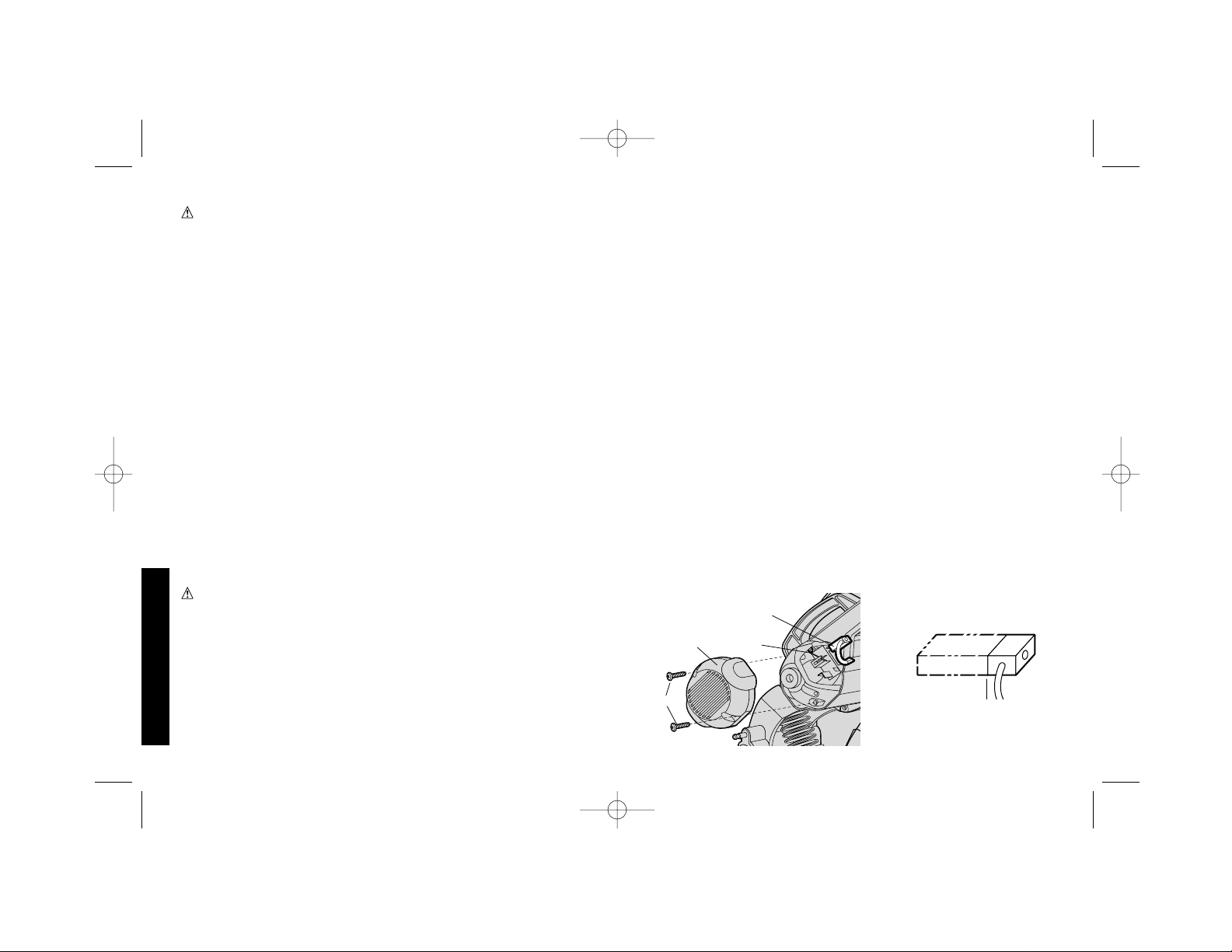
herramienta.
· Coloque la pieza de trabajo en el paso del recorrido descendente
de la hoja (Figura 10) Los materiales deben estar firmemente
afianzados y debidamente soportados para reducir vibraciones.
SIN EXCEPCIÓN ALGUNA.
· Nunca intente cortar un atado de varias piezas. Córtelas
individualmente.
· Coloque la pieza de trabajo de manera que la hoja corte pase
por la sección transversal más pequeña.
· En lo posible, evite cortar superficies grandes, planas,
horizontales. Entre menor sea el número de dientes de la hoja
que hacen contacto con la pieza de trabajo durante el corte,
menor será el calor producido y más se prolongará la vida de la
hoja.
2. Las siguientes condiciones son seña que la hoja está gastada y
que es necesario volverla a afilar, o reemplazarla:
· Rendimiento de corte inadecuado.
· Crea más chispas que astillas durante un corte. .
· Aumenta el zumbido de la operación de la hoja.
Instrucciones para montaje permanente
(Fig. 14)
(Recomendado cuando se van a hacer múltiples cortes en el mismo
Español
ADVERTENCIA: Verifique que la hoja no está tocando la pieza
de trabajo cuando se arranca la herramienta.
PIEZA DE TRABAJO CUANDO SE ENCIENDE LA
HERRAMIENTA.
Lista de control para el proceso de aserrado
1. Antes de prender la herramienta, confirme que:
· La herramienta está instalada firmemente en una superficie
estable.
· La hoja está instalada correctamente y el perno de la hoja está
bien apretado.
·El cerco está en la posición correcta y asegurado en su lugar.
·La pieza de trabajo está firmemente sostenida por un torno de
banco y sujeta con abrazaderas verticales según se ha indicado.
· El ajuste del deflector de astillas es correcto
2. Arranque el motor y deje que la hoja alcance su velocidad plena.
3. Baje el mango suavemente para hacer contacto inicial con la
pieza de trabajo. Una vez que haga contacto, aumente el
régimen de alimentación, permitiendo que la hoja haga el
trabajo. Aminore la velocidad justo antes de terminar el corte.
4. Una vez que haya terminado el corte, apague la herramienta y
mantenga las manos fuera del alcance de la hoja, hasta que deje
de girar.
ADVERTENCIA Cuando corte piezas pequeñas (inferiores a 2,54
cm), los residuos pueden ser lanzados hacia la parte trasera de la
herramienta.
Buen cuidado/ Prácticas de corte
Los dientes de la hoja están hechos de un material de carburo que
aunque muy duro, es deleznable. La vibración aumenta las cargas
laterales que pueden causar que se desconchen o astillen los
dientes o que se raje la hoja. He aquí unos consejos muy
importantes que le ayudarán a prolongar la vida de la hoja y de la
.3"
(8 MM)
C
FIG. 16
A
B
D
FIG. 17
392736-01,00,DW872 6/29/00 9:01 AM Page 30
Page 33

31
Español
lugar)
1. Perfore cuatro agujeros de 5/16" por la superficie de trabajo.
(Figura 14)
2. Inserte tornillos de 1/4-20 por dichos agujeros hasta llegar a la
base y por los agujeros en la superficie de montaje. La longitud
aproximada de los tornillos debe ser el espesor de la superficie
de montaje más 4 pulgadas.
Instalación del soporte
1. Corte dos tablas de 20" long. x 2" alto x 4" ancho
aproximadamente.
2. Coloque la herramienta en lugar de trabajo deseado.
3. Coloque las tablas a ambos lados de la herramienta, lo más
cerca posible de ella, y afiáncelas a la superficie de trabajo.
Mantenimiento
Inspección y reemplazo de las escobillas del motor (Fig. 16)
Confirme que la herramienta está desconectada antes de examinar
las escobillas. Es necesario examinar las escobillas regularmente
para ver si muestran señales de desgaste. Para examinar las
escobillas, destornille los dos tornillos de cabeza en los extremos (A)
y quite la cabeza (B). Para sacar las escobillas, (C) primero
desconecte la conexión del terminal cable de derivación. Luego,
con mucho cuidado, aparte hacia atrás el resorte de la escobilla (D)
sacándolo de la caja de las escobillas y retire la escobilla. Las
escobillas deberían deslizarse sin problemas en su caja. Si las
escobillas están gastadas a .3” (8mm) (vea la Figura 17) es
necesario reemplazarlas. Para volver a instalarlas, mueva el resorte
hacia atrás fuera de la caja de las escobillas, inserte la escobilla,
vuelva a poner el resorte en su lugar verificando que está
presionando contra la escobilla y que no está tocando la caja de
escobillas. Vuelva a conectar el terminal del cable de derivación,
luego reemplace la cabeza del tornillo extremo y los dos tornillos.
Limpieza
Se recomienda sacar el polvo y arenilla del alojamiento principal y
del deflector de astillas utilizando una aspiradora de aire. Esta tarea
debe hacerse toda vez que se vea que se empiezan a acumular
polvo alrededor de las orificios de ventilación..
Accesorios
Las hojas se pueden adquirir de su distribuidor local o de un centro
de servicio autorizado, a un costo adicional. Si necesita ayuda en
encontrar este accesorio para su herramienta, por favor contacte a:
D
EWALT Industrial Tool Co., 701 East Joppa Road, Baltimore, MD
21286
PRECAUCIÓN: No se recomienda utilizar ningún otro accesorio
con esta herramienta , pues puede ser peligroso.
Nota Importante
Para garantizar la SEGURIDAD y CONFIABILIDAD del producto,
toda reparación, mantenimiento y ajustes aparte de los que trata este
manual deben ser hechos en centros de servicio autorizados o por
cualquier otra entidad de servicio calificada, siempre usando partes
idénticas de reemplazo.
Lubricación
Esta herramienta cuenta con cojinetes de bolas de tipo cerrado, con
sello de grasa. En la fábrica se ha empacado suficiente lubricación
en estos cojinetes para dure la vida de la herramienta. .
Hay que lubricar los engranajes cada 60 a 90 días dependiendo del
uso. Esta lubricación debe intentarla solamente personal de
reparación con experiencia en herramientas mecánicas, como los
mecánicos en los centros de servicio D
EWALT. Es necesario limpiar
la caja de engranajes y aplicarle 1/2 oz. (16 gramos) de Lubricante
D
EWALT, Parte No. 790206 (tubo de 6 oz.) .
Garantía total
Las herramientas mecánicas de servicio pesado de DEWALT están
392736-01,00,DW872 6/29/00 9:01 AM Page 31
Page 34

32
garantizadas por un año contado desde su fecha de compra.
D
EWALT se compromete a reparar, sin costo alguno, cualquier
defecto debido a materiales o elaboración defectuosa. Para mayor
información sobre la garantía, sírvase llamar al 1-900-4-D
EWALT.
Esta garantía no es de aplicación a los accesorios o a daños
causados cuando otras personas han hecho o han intentando hacer
reparaciones . Esta garantía le confiere derechos legales
específicos, además los compradores pueden tener otros derechos
que varían según el estado o la provincia.
Además de la garantía, las herramientas DeWALT están cubiertas
por nuestra:
GARANTÍA DE SATISFACCIÓN SIN RIESGO 30 DÍAS
Si no está completamente satisfecho con el funcionamiento de su
herramienta de uso industrial D
EWAL T, simplemente devuélvala a un
vendedor participante dentro de 30 días para recibir un reembolso
total de su precio de compra. Es posible que se necesite presentar
prueba de compra.
Español
392736-01,00,DW872 6/29/00 9:01 AM Page 32
Page 35

Guía para Solución de Problemas
PROBLEMA! La herramienta NO ENCIENDE
QUÉ PASA? QUÉ HACER ...
1.La herramienta no está conectada. 1.Conecte la sierra.
2.Se ha fundido el fusible o disparado el circuito. 2.Reemplace el fusible o vuelva a iniciar el panel de circuitos.
3.Cordón dañado. 3.Reemplace el cordón en un centro de servicio autorizado.
4.Escobillas gastados. 4.Reemplace las escobillas en un centro de servicio autorizado.
PROBLEMA! la sierra no corta bien
QUÉ PASA? QUÉ HACER ...
1. Hoja roma. 1. Reemplace o afile la hoja. Consulte Buen Cuidado/Prácticas, págs. 28.
2. La pieza de trabajo no está colocada ni 2. Afiance la pieza de trabajo y sopórtela debidamente. Consulte Posicionamiento y Sujeción del Material, página 28.
afianzada debidamente .
PROBLEMA! la hoja no alcanza velocidad
QUÉ PASA? QUÉ HACER ...
1.El cordón de extensión es muy ligero o muy largo. 1.Reemplácelo por uno de tamaño adecuado. Vea la tabla en la página 23.
2.Baja tensión. 2.Comuníquese con su compañía eléctrica.
3.Baja tensión del generador. 3.Confirme la tensión de salida del generador. Reduzca el número de herramientas energizadas por
el generador.
PROBLEMA! la herramienta vibra excesivamente DURANTE UN CORTE
QUE PASA? QUÉ HACER ...
1.Tal vez la herramienta no esté asegurada 1.Apriete todos los elementos de montaje. Consulte la página 28, Procedimientos para io banco de trabajo.
firmemente a un puesto instalación permanente.
2.Hoja de corte dañada. 2.Reemplace la hoja.
3.La pieza de trabajo no está sujetada debidamente. 3.Consulte, colocación del material y Prácticas, página 28 y Buen Cuidado y Prácticas de Corte, páginas 7 y 8.
PROBLEMA! Los cortes no son precisos
QUE PASA? QUÉ HACER ...
1. El cerco no está ajustado correctamente. 1. Confirme la posición del cerco y haga los ajustes correspondientes. Vea Operación del Cerco, página 26.
2. La hoja no está alineada con el cerco. 2. Verifique la posición y ajústela. Vea Ajuste al Angulo del Cerco, página 26.
3. Fuerza excesiva para hacer un corte. 3. Reduzca la presión de corte, deje que la hoja haga el trabajo.
4. La pieza de trabajo se mueve. 4. Asegure la pieza de trabajo firmemente en su lugar. Vea Posicionamiento y Sujeción del Material, página 27.
Confirme que el material descansa plano sobre la base.
PROBLEMA! No se puede mover el brazo
QUÉ PASA? QUÉ HACER ...
1. La protección auto-retractable de la hoja 1.Revise la hoja a ver si hay partes averiadas. Vea si hay demasiadas astillas en la protección. Repárela, o reemplácela, según sea
no se mueve. necesario.
2. El fiador del seguro está puesto. 2. Empuje el brazo hacia abajo levemente, saque el fiador del seguro. Vuelva a levantar el brazo. Vea página 25.
PROBLEMA! el material se mueve durante un corte
QUÉ PASA? QUÉ HACER ...
1. El cerco se desliza o la pieza de trabajo no se 1.Vea Posicionamiento y Sujeción del Material, página 28.
ha puesto en la posición correcta, o no está
debidamente sujetada.
2.El torno está muy flojo 2.Apriete las prensa vertical auxiliar
3.Excesiva fuerza de corte. 3.Reduzca la fuerza de corte.
33
Español
392736-01,00,DW872 6/29/00 9:01 AM Page 33
 Loading...