

Page 1

DEWALT Industrial Tool Company, P.O. Box 158, 626 Hanover Pike, Hampstead, MD 21074 Printed in U.S.A. (JULY97-CD-1) Form No. 384404
DW628 Copyright © 1997
Garantía completa
Las herramientas industriales DEWAL Testán garantizadas durante un
año a partir de la fecha de compra. Repararemos, sin cargos,
cualquier falla debida a material o mano de obra defectuosos. Para
obtener información sobre reparaciones en garantía, llame por favor al
326-7100. Esta garantía no se aplica a los accesorios ni a daños
causados por reparaciones efectuadas por terceras personas. Esta
garantía le otorga derechos legales específicos, y usted puede tener
otros derechos que pueden variar de estado a estado.
En adición a la garantía, las herramientas DEWALT están amparadas
por nuestra:
GARANTÍA DE SATISFACCIÓN SIN RIESGO POR 30 DÍAS
Si usted no se encuentra completamente satisfecho con el desempeño
de su herramienta industrial D
EWALT, sencillamente devuélvala a los
vendedores participantes durante los primeros 30 días después de la
fecha de compra para que le efectúen un reembolso completo. Por
favor regrese la unidad completa, con el transporte pagado. Se puede
requerir prueba de compra.
384404/DW628 5/2/02 1:39 PM Page 2
Page 2

INSTRUCTION MANUAL
GUIDE D'UTILISATION
MANUAL DE INSTRUCCIONES
DW628
3.5 HP Router
Toupie de 3,5 HP
Rebajadora de 3,5 HP
INSTRUCTIVO DE OPERACIÓN, CENTROS DE SERVICIO Y PÓLIZA
DE GARANTÍA. ADVERTENCIA: LÉASE ESTE INSTRUCTIVO ANTES
DE USAR EL PRODUCTO.
384404/DW628 5/2/02 1:39 PM Page 3
Page 3
Important Safety Instructions
WARNING: When using electric tools, basic safety precautions
should always be followed to reduce risk of fire, electric shock, and
personal injury, including the following:
READ ALL INSTRUCTIONS
Grounding Instructions
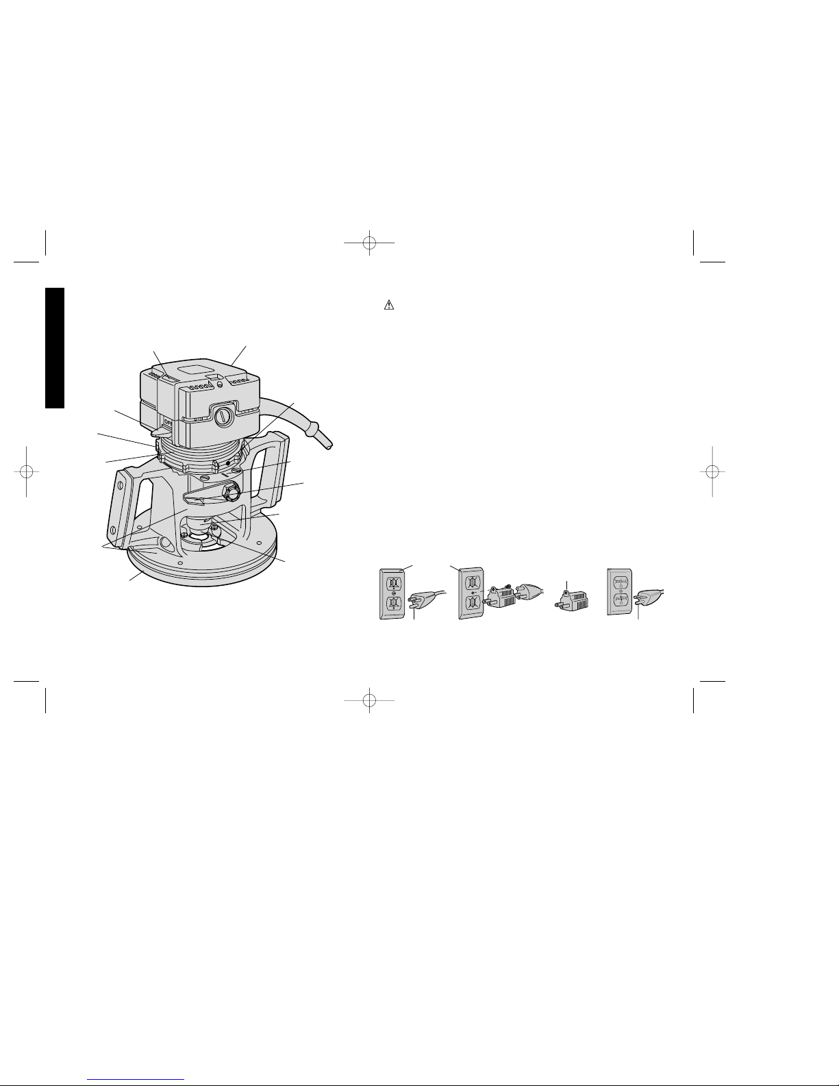
This tool should be grounded while in use to protect the operator from
electric shock. The tool is equipped with a 3-conductor cord and 3prong grounding type plug to fit the proper grounding type receptacle.
The green (or green and yellow) conductor in the cord is the
grounding wire. Never connect the green (or green and yellow) wire
to a live terminal. If your unit is intended for use on less than 150 V,
it has a plug that looks like that shown in sketch A. If it is for use on
150 to 250 V, it has a plug that looks like that shown in sketch D. An
adapter, sketches B and C, is available for connecting sketch A type
plugs to 2-prong receptacles. The green-colored rigid ear, lug, or the
like, extending from the adapter must be connected to a permanent
ground, such as a properly grounded outlet box. No adapter is
available for a plug as shown in sketch D. ADAPTER SHOWN IN
FIGURES B and C IS NOT FOR USE IN CANADA.
English
IF YOU HAVE ANY QUESTIONS OR COMMENTS ABOUT THIS
OR ANY D
EWALT TOOL, CALL US TOLL FREE AT:
1-800-4-DEWALT (1-800-433-9258)
SWITCH PROBE
END CAP
RING LOCK
SCRIBE LINE
CLAMP
LEVER
COLLET
ADAPTER
COLLET NUT
SUB BASE
BASE
MOTOR
UNIT
SWITCH
ADJUSTING
RING
AB CD
GROUNDING PIN
GROUNDED
OUTLET
BOX
GROUNDING
MEANS
GROUNDING PIN
ADAPTER
384404/DW628 5/2/02 1:39 PM Page 4
Page 4

Safety Instructions For All Tools
• KEEP WORK AREA CLEAN. Cluttered areas and benches invite
injuries.
• CONSIDER WORK AREA ENVIRONMENT. Don’t expose power
tools to rain. Don’t use power tools in damp or wet locations. Keep
work area well lit. Do not use tool in presence of flammable liquids
or gases.
• GUARD AGAINST ELECTRIC SHOCK. Prevent body contact
with grounded surfaces. For example; pipes, radiators, ranges, and
refrigerator enclosures.
• KEEP CHILDREN AWAY. Do not let visitors contact tool or
extension cord. All visitors should be kept away from work area.
• STORE IDLE TOOLS. When not in use, tools should be stored in
dry, and high or locked-up place — out of reach of children.
• DON’T FORCE TOOL. It will do the job better and safer at the
rate for which it was intended.
• USE RIGHT TOOL. Don’t force small tool or attachment to do the
job of a heavy-duty tool. Don’t use tool for purpose not intended.
• DRESS PROPERLY. Do not wear loose clothing or jewelry. They
can be caught in moving parts. Rubber gloves and non-skid
footwear are recommended when working outdoors. Wear
protective hair covering to contain long hair.
• USE SAFETY GLASSES. Also use face or dust mask if cutting
operation is dusty.
• DON’T ABUSE CORD. Never carry tool by cord or yank it to
disconnect from receptacle. Keep cord from heat, oil, and sharp
edges.
• SECURE WORK. Use clamps or a vise to hold work. It’s safer than
using your hand and it frees both hands to operate tool.
• DON’T OVERREACH. Keep proper footing and balance at all
times.
• MAINTAIN TOOLS WITH CARE. Keep tools sharp and clean for
better and safer performance. Follow instructions for lubricating
and changing accessories. Inspect tool cords periodically and if
damaged, have repaired by authorized service facility. Inspect
extension cords periodically and replace if damaged. Keep
handles dry, clean, and free from oil and grease.
• DISCONNECT OR LOCK OFF TOOLS when not in use, before
servicing, and when changing accessories, such as blades, bits,
cutters.
• REMOVE ADJUSTING KEYS AND WRENCHES. Form habit of
checking to see that keys and adjusting wrenches are removed
from tool before turning it on.
• AVOID UNINTENTIONAL STARTING. Don’t carry tool with finger
on switch. Be sure switch is off when plugging in.
• EXTENSION CORDS. Use only 3-wire extension cords that have
3-prong grounding-type plugs and 3-pole receptacles that accept
the tool’s plug. Replace or repair damaged cords. Make sure your
extension cord is in good condition. When using an extension cord,
be sure to use one heavy enough to carry the current your product
will draw. An undersized cord will cause a drop in line voltage
resulting in loss of power and overheating. The following table
shows the correct size to use depending on cord length and
nameplate ampere rating. If in doubt, use the next heavier gage.
The smaller the gage number, the heavier the cord.
Minimum Gage for Cord Sets
Volts Total Length of Cord in Feet
120V 0-25 26-50 51-100 101-150
240V 0-50 51-100 101-200 201-300
Ampere Rating
More Not more American Wire Gage (AWG)
Than Than
0- 6 18161614
6 - 10 18 16 14 12
10- 1216161412
12 - 16 14 12 Not Recommended
• OUTDOOR USE EXTENSION CORDS. When tool is used
outdoors, use only extension cords intended for use outdoors and
1
English
384404/DW628 5/2/02 1:39 PM Page 1
Page 5
removing the motor unit from the base. ALWAYS BE SURE THAT
THE CLAMP LEVER IS IN THE LOCKED (DOWN) POSITION
WHEN ROUTING.
The orientation of the lever can be changed if desired by loosening
the lock nut that fastens it to the router and rotating the lever to the
desired position. Retighten the lock nut.
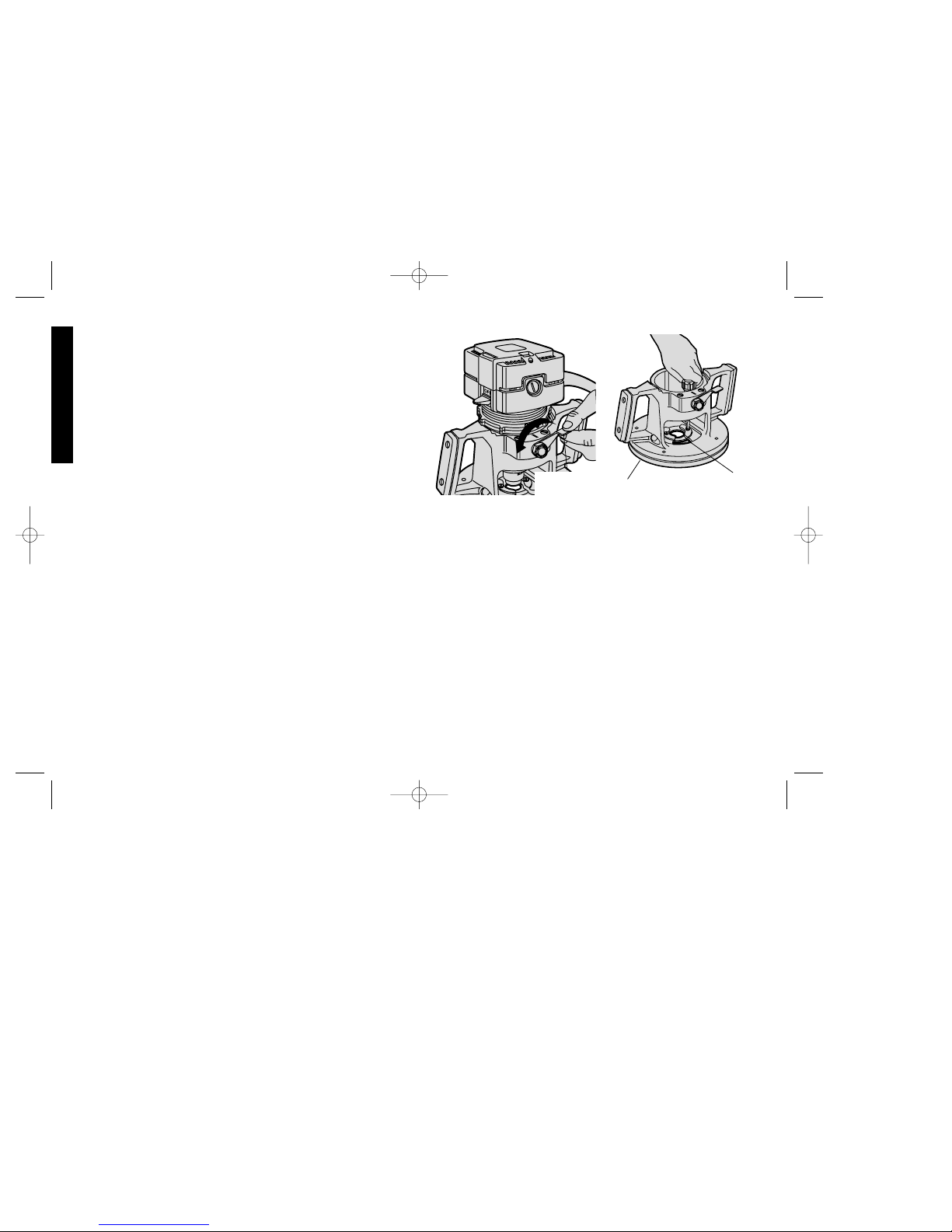
Sub Base
Turn Off and Unplug Router
The sub base on your router has been specifically designed to permit
better visibility than conventional routers but retain the ability to use
template guides. The guide adapter, if not needed, can be easily
removed for even more visibility. To remove the adapter raise the
Clamp Lever and lift the motor assembly out of the router base. This
will enable you to reach and remove the two screws in the base
which hold the guide adapter in place, as shown in Figure 2.
When you reinstall the motor unit, be sure to align the Guide Screw
(Figure 3) with the slot in the router base.
LOCKING
LEVER
2
so marked.
• STAY ALERT. Watch what you are doing. Use common sense.
Do not operate tool when you are tired.
• CHECK DAMAGED PARTS. Before further use of the tool, a
guard or other part that is damaged should be carefully checked
to determine that it will operate properly and perform its intended
function. Check for alignment of moving parts, binding of moving
parts, breakage of parts, mounting, and any other conditions that
may affect its operation. A guard or other part that is damaged
should be properly repaired or replaced by an authorized service
center unless otherwise indicated elsewhere in this instruction
manual. Have defective switches replaced by authorized service
center. Do not use tool if switch does not turn it on and off.
SAVE THESE INSTRUCTIONS
Motor
Your DEW ALT tool is powered by a DEWAL T-built motor . Be sure your
power supply agrees with the nameplate marking.
120 Volts 60Hz or “AC/DC” means your tool may be operating with
alternating or direct current.
Voltage decrease of more than 10% will cause loss of power and
overheating. All D
EWAL Ttools are factory tested; if this tool does not
operate, check the power supply.
Clamp Lever
Turn Off and Unplug Router.
In order to lock the position of the router motor unit in the router base,
a lever has been provided on the side of the tool, as shown in Figure
1.
To lock the motor unit in place, push the lever all the way down; to
release the motor, raise the lever up to about a right angle to the
tool. Use this loosened position for making depth adjustments and
English
FIG. 1 FIG. 2
SUB BASE
GUIDE
ADAPTER
384404/DW628 5/2/02 1:39 PM Page 2
Page 6

Sub Base Alignment For Template Routing
The guide adapter is aligned with the collet at the time of
manufacture, but the two may become misaligned during shipping
and handling, particularly if the tool is dropped. To properly align the
collet with the guide adapter follow the steps below.
1. Turn Off and Unplug Router.
2. Raise the Clamp Lever and remove the motor unit from the router
base.
3. Remove the Guide Screw and the Adjusting Ring shown in Figure 3.
4. Loosen the 4 screws in the Sub Base, as shown in Figure 4.
5. Re-insert the Guide Screw (not the Adjusting Ring) in the motor
unit and insert the motor unit into the router base. (Make sure
that you align the Guide Screw with the slot in the router base.)
6. Lower the motor unit until the collet adapter extends through the
guide adapter, as shown in Figure 4. Adjust the Sub Base until the
collet adapter fits through it.
7. Tighten the four screws in the Sub Base and remove the motor
unit from the router base.
8. Remove the Guide Screw and re-install the Adjusting Ring.
9. Install the Guide Screw and re-insert the motor unit into the router
base. (Be sure to align the guide screw with the slot in the base.)
10. The template guide is now aligned with the collet.
NOTE: When installing the guide screw in the above section
remember that it must be tightened firmly so that the head is flush
against the side of the motor unit.
Attaching Bits and Cutters
Turn Off and Unplug Router
Insert the shank of the desired bit or cutter into the collect as far as it
will go, then pull it out slightly (about 1/32”,.793 mm). Use the
wrenches provided to securely tighten the collet nut. One wrench
holds the collet adapter and the other tightens the collet nut.
A special coating has been put on the collet and collet nut to increase
the bit holding power. Use only the wrenches provided with your
router to tighten the collet nut. Other tools may damage the coating
through overtightening.
Depth Adjustment
Turn Off and Unplug Router
Loosen the Clamp Lever by raising it fully. Adjust the depth setting of
the router bit by turning the Adjusting Ring shown in Figure 5. To
raise the bit away from the work surface, turn the ring clockwise (as
viewed from the top of the tool) and to lower the bit into the work, turn
it counterclockwise.Directly over the Clamp Lever pivot point is a
line scribed into the aluminum housing, as shown in Figure 5. As the
ring is rotated, the raised lugs on the ring will pass over this line. Each
time a lug passes the line, the bit is raised or lowered 1/64" (.396
mm). Every full revolution of the Adjusting Ring accounts for
3
English
FIG. 3
GUIDE SCREW
ADJUSTING
RING
GUIDE
ADAPTER
COLLET
ADAPTER
FIG. 4
SCREWS
384404/DW628 5/2/02 1:39 PM Page 3
Page 7
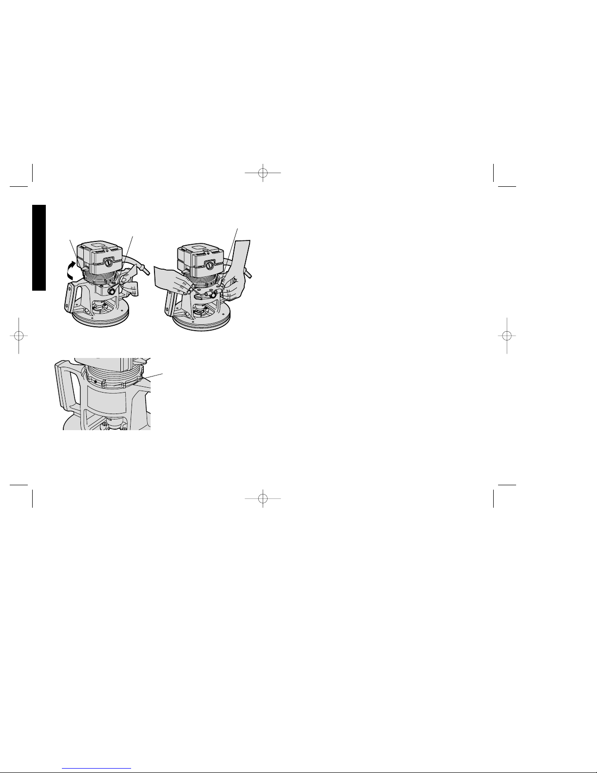
1/8"(3.175 mm) of adjustment either up or down.
The lugs are consecutively numbered for convenience. For faster
adjustments, lift the motor housing slightly and spin the Adjusting
Ring.
Duplicating specific depths of cut, such as hinge butt mortises, can
be done quickly and accurately by following the steps below.
1. TURN OFF AND UNPLUG ROUTER.
2. Lower the router bit until it just touches the workpiece. (Refer to
preceding section on “DEPTH ADJUSTMENT.”)
3. Lock the Clamp Lever
4. Raise the Adjusting Ring by rotating it counterclockwise until the
hinge will just fit between the top edge of the router base and the
bottom of the Adjusting Ring, as shown in Figure 6.
5. Remove the hinge and invert the router to prevent the bit from
marring the work surface.
6. Unlock the Clamp Lever and allow the base to fall to the new
setting. Lock the Clamp Lever in place and the depth is set. The
router will now cut to the exact thickness of the hinge.
Adjusting Ring Lock
Turn Off and Unplug Router.
To prevent the Adjusting Ring from rotating due to vibration of the
router, a nylon set screw has been provided in the ring. When the ring
is set as desired, tighten this set screw, shown in Figure 7. Be careful
to avoid overtightening which will strip the soft nylon screw. The set
screw can be used whenever desired, or never at all.
On/Off Switch
The on/off switch is located on the side of the router, just above the
hand grip, Figure 8. T o turn on the router , raise the on/of f switch lever
with your thumb while gripping the tool. T o turn of f the router, pull the
switch lever down. When the router is running, you will notice a probe
4
English
FIG. 7
OFF
OFF
FIG. 5
FIG. 6
CLAMP
LEVER
ADJUSTING
RING
HINGE
NYLON RING
LOCK
384404/DW628 5/2/02 1:39 PM Page 4
Page 8

extending from the top of the router. This probe is connected to the
on/off switch lever and can be used to turn off the router by pushing
it down toward the end cap. This probe also prevents the router from
inadvertently being turned on while it is inverted and resting on its
end cap. The end cap is designed so that the router can be inverted
for temporary storage, when changing the work piece, and while
changing router bits. Figure 9.
CAUTION: Some wood contains preservatives such as copper
chromium arsenate (CCA) which can be toxic. When cutting or
sanding these materials extra care should be taken to avoid
inhalation and minimize skin contact.
Accessories
Recommended accessories for use with your tool are available at
extra cost from your local dealer or authorized service center. If you
need assistance in locating any accessory for your tool, call us toll
free at: 1-800-4-D
EWALT (1-800-433-9258) or contact:
DEWALT Industrial Tool Company
626 Hanover Pike, P.O. Box 158
Hampstead, MD. 21074-0158
CAUTION: The use of any other accessory not recommended for
use with this tool could be hazardous.
Important
To assure product SAFETY and RELIABILITY, repairs, maintenance
and adjustment (including brush inspection and replacement) should
be performed by authorized service centers or other qualified service
organizations, always using identical replacement parts.
Full Warranty
DEWALT heavy duty industrial tools are warranted for one year from
date of purchase. We will repair, without charge, any defects due to
faulty materials or workmanship. For warranty repair information,
call 1-800-4-D
EWAL T. This warranty does not apply to accessories or
damage caused where repairs have been made or attempted by
others. This warranty gives you specific legal rights and you may
have other rights which vary in certain states or provinces.
In addition to the warranty, D
EWALT tools are covered by our:
30 DAY NO RISK SATISFACTION GUARANTEE
If you are not completely satisfied with the performance of your
D
EWAL T heavy duty industrial tool, simply return it to the participating
seller within 30 days for a full refund. Please return the complete unit,
transportation prepaid. Proof of purchase may be required.
5
English
FIG. 9FIG. 8
ON/OFF
SWITCH
PROBE LOCATION
PROBE
384404/DW628 5/2/02 1:39 PM Page 5
Page 9

6
Français
Importantes mesures de sécurité
AVERTISSEMENT : Afin de réduire les risques d’incendie, de
secousses électriques ou de blessures lorsqu’on utilise des outils
électriques, il faut toujours respecter les mesures de sécurité
suivantes.
LIRE TOUTES LES DIRECTIVES.
Mise à la terre
L’outil doit être mis à la terre lorsqu’on s’en sert afin de protéger
l’utilisateur contre les secousses électriques. D’ailleurs, l’outil est
muni d’un cordon trifilaire et d’une fiche à trois broches convenant
aux prises mises à la terre. Le conducteur vert (ou vert et jaune) du
cordon constitue la mise à la terre. Ne jamais relier le conducteur
vert (ou vert et jaune) à une borne sous tension. Lorsque l’outil est
conçu pour être alimenté à une tension maximale de 150 volts, sa
fiche ressemble à celle illustrée à la figure A. Lorsque l’outil est
conçu pour être alimenté à une tension maximale de 150 à250 volts,
sa fiche ressemble à celle illustrée à la figure D. Il existe des
adaptateurs (figures B et C) pour brancher le type de fiche illustré à
la figure A dans des prises à deux trous. L’oreille ou la cosse rigide
et verte doit être reliée à une mise à la terre permanente, comme une
prise bien mise à la terre. Il n’y a pas d’adaptateur pour les fiches
semblables à celle illustrée à la figure
D. AU CANADA, ON NE PEUT
PAS SE SERVIR DE L’ADAPTATEUR ILLUSTRÉ AUX FIGURES B ET C.
POUR TOUT RENSEIGNEMENT SUPPLÉMENTAIRE SUR CET
OUTIL OU TOUT AUTRE OUTIL D
EWALT, COMPOSER SANS
FRAIS LE NUMÉRO:
1 800 4-DEWALT (1 800 433-9258)
BOUCHON D’EXTRÉMITÉ
DISPOSITIF DE
VERROUILLAGE
DE LA BAGUE
LIGNE
GRAVÉE
LEVIER DE
SERRAGE
ADAPTATEUR
POUR MANDRIN
À PINCE
ÉCROU DU
MANDRIN À
PINCE
SOUS-PLAQUE
PLAQUE
BLOC-
MOTEUR
BAGUE DE
RÉGLAGE
INTERRUPTEUR
POINTE DE
L’INTERRUPTEUR
AB CD
BROCHE DE PRISE
MISE À LA TERRE
BROCHE DE PRISE
MISE À LA TERRE
PRISE MISE
À LA TERRE
DISPOSITIF DE
MISE À LA TERRE
ADAPTATEUR
384404/DW628 5/2/02 1:39 PM Page 6
Page 10

7
Français
ou d’un étau. On peut alors se servir des deux mains pour faire
fonctionner l’outil, ce qui est plus sûr.
• NE PAS DÉPASSER SA PORTÉE. Toujours demeurer dans une
position stable et garder son équilibre.
• PRENDRE SOIN DES OUTILS. Conserver les outils propres pour
qu’ils donnent un rendement supérieur et sûr. Suivre les directives
concernant la lubrification et le remplacement des accessoires.
Inspecter régulièrement le cordon de l’outil et le faire réparer au
besoin à un atelier d’entretien autorisé. Inspecter régulièrement
les cordons de rallonge et les remplacer lorsqu’ils sont
endommagés. S’assurer que les poignées sont toujours propres,
sèches et libres de toute tache d’huile ou de graisse.
• DÉBRANCHER OU VERROUILLER EN POSITION HORS
TENSION LES OUTILS NON UTILISÉS. Respecter cette mesure
lorsqu’on ne se sert pas de l’outil, ou qu’on doit le réparer ou en
changer un accessoire (comme une lame, un foret ou un couteau).
• ENLEVER LES CLÉS DE RÉGLAGE. Prendre l’habitude de
vérifier si les clés de réglage ont été retirées avant de faire
démarrer l’outil.
• ÉVITER LES DÉMARRAGES ACCIDENTELS. Ne pas laisser le
doigt sur l’interrupteur lorsqu’on transporte l’outil. S’assurer que
l’interrupteur est à la position hors circuit lorsqu’on branche l’outil.
•
CORDONS DE RALLONGE. Utiliser seulement des cordons de
rallonge trifilaires ayant une fiche à 3 broches ainsi qu’une prise à
3 trous acceptant la fiche de l’outil. Remplacer ou réparer les
cordons de rallonge endommagés. S’assurer que le cordon de
rallonge est en bon état. Lorsqu’on se sert d’un cordon de
rallonge, s’assurer qu’il est de calibre approprié pour la tension
nécessaire au fonctionnement de l’outil. L’utilisation d’un cordon
de calibre inférieur occasionne une baisse de tension entraînant
une perte de puissance et la surchauffe. Le tableau suivant
indique le calibre approprié selon la longueur du cordon et les
mentions de la plaque signalétique de l’outil. En cas de doute,
utiliser un cordon de calibre supérieur. Le chiffre indiquant le
Mesures de sécurité pour tous les outils
• BIEN DÉGAGER LA SURFACE DE TRAVAIL. Des surfaces et
des établis encombrés peuvent être la cause de blessures.
• TENIR COMPTE DU MILIEU DE TRAVAIL. Protéger les outils
électriques de la pluie. Ne pas s’en servir dans des endroits
humides ou mouillés. Bien éclairer la surface de travail. Ne pas
utiliser l’outil en présence de liquides ni de gaz inflammables.
• SE PROTÉGER CONTRE LES SECOUSSES ÉLECTRIQUES.
Éviter tout contact avec des objets mis à la terre, comme des
tuyaux, radiateurs, cuisinières, réfrigérateurs et autres objets du
genre.
• ÉLOIGNER LES ENFANTS. Tous les visiteurs doivent être tenus
à l’écart de l’aire de travail et il faut les empêcher de toucher à
l’outil ou au cordon de rallonge.
• RANGER LES OUTILS INUTILISÉS. Il faut ranger les outils dans
un endroit sec, situé en hauteur ou fermé à clé, hors de la portée
des enfants.
• NE JAMAIS FORCER L’OUTIL. Afin d’obtenir un rendement sûr
et efficace, utiliser l’outil à son rendement nominal.
• UTILISER L’OUTIL APPROPRIÉ. Ne jamais exiger d’un petit outil
ou d’un accessoire le rendement d’un outil de fabrication plus
robuste. Se servir de l’outil selon l’usage prévu.
• PORTER DES VÊTEMENTS APPROPRIÉS. Éviter de porter des
vêtements amples et des bijoux qui peuvent être happés par les
pièces en mouvement. Porter des gants de caoutchouc et des
chaussures à semelle antidérapante pour travailler à l’extérieur.
Protéger la chevelure si elle est longue.
• PORTER DES LUNETTES DE SÉCURITÉ. Porter également un
masque respiratoire si le travail de coupe produit de la poussière.
• NE PAS MANIPULER LE CORDON DE FAÇON ABUSIVE. Ne
pas transporter l’outil par le cordon ni tirer sur ce dernier pour le
débrancher de la prise. Éloigner le cordon des sources de chaleur,
des flaques d’huile et des arêtes tranchantes.
• ASSUJETTIR LA PIÈCE. Immobiliser la pièce à l’aide de brides
384404/DW628 5/2/02 1:39 PM Page 7
Page 11

8
calibre est inversement proportionnel au calibre du cordon.
Calibre minimal des cordons de rallonge
Tension Longueur totale du cordon en pieds
120 V De 0 à 25De 26 à 50 De 51 à 100 De 101 à 150
240 V De 0 à 50De 51à 100 De 101 à 200 De 201 à 300
Intensité (A)
Au Au Calibre moyen de fil
moins plus
0- 6 18161614
6 - 10 18 16 14 12
10- 1216161412
12 - 16 14 12 Non recommandé
• CORDONS DE RALLONGE PRÉVUS POUR L’EXTÉRIEUR.
Lorsque l’outil est utilisé à l’extérieur, ne se servir que d’un cordon
de rallonge conçu pour l’extérieur et portant la mention appropriée.
• DEMEURER VIGILANT. Travailler avec vigilance et faire preuve
de bon sens. Ne pas se servir de l’outil lorsqu’on est fatigué.
• VÉRIFIER LES PIÈCES ENDOMMAGÉES. Avant de continuer à
utiliser l’outil, il faut vérifier si le protecteur ou toute autre pièce
endommagée remplit bien la fonction pour laquelle il a été prévu.
Vérifier l’alignement et les attaches des pièces mobiles, le degré
d’usure des pièces et leur montage, ainsi que tout autre facteur
susceptible de nuire au bon fonctionnement de l’outil. Faire
réparer ou remplacer tout protecteur ou toute autre pièce
endommagée dans un centre de service autorisé, sauf si le
présent guide fait mention d’un avis contraire. Confier le
remplacement de tout interrupteur défectueux à un centre de
service autorisé. Ne jamais se servir d’un outil dont l’interrupteur
est défectueux.
CONSERVER CES MESURES.
Moteur
Un moteur DEWALT alimente l’outil DEWALT. Veiller à ce que la
tension d’alimentation soit conforme aux exigences de la plaque
signalétique de l’outil.
La mention “120 volts, 60 Hz” ou “c.a./c.c.” signifie que l’outil peut
fonctionner à l’aide de courant alternatif ou continu.
Une baisse de tension de plus de 10 p. 100 entraîne une perte de
puissance et la surchauffe. Tous les outils D
EWALT sont essayés
avant de quitter l’usine. Lorsque celui-ci refuse de fonctionner,
vérifier la source de courant électrique.
Levier de blocage
Mettre la toupie hors tension et la débrancher.
Afin de bloquer le bloc-moteur dans la plaque de la toupie, il y a un
levier sur le côté de l’outil (fig. 1).
Pour bloquer le bloc-moteur en place, abaisser à fond le levier; pour
dégager le bloc-moteur, soulever le levier jusqu’à environ un angle
droit par rapport à l’outil. Utiliser cette position déverrouillée pour
Français
FIG. 1 FIG. 2
LEVIER DE
VERROUILLAGE
ADAPTATEUR
POUR GUIDE
SOUS-
PLAQUE
384404/DW628 5/2/02 1:39 PM Page 8
Page 12

régler la profondeur de coupe et pour retirer le bloc-moteur de la
plaque. TOUJOURS S’ASSURER QUE LE LEVIER DE BLOCAGE
EST EN POSITION VERROUILLÉE (ABAISSÉE) LORSQU’ON SE
SERT DE L’OUTIL.
On peut modifier le sens du levier au besoin en desserrant le contreécrou que retient le levier à la toupie et en faisant tourner le levier à
la position voulue. Resserrer le contre-écrou.
Sous-plaque
Mettre la toupie hors tension et la débrancher.
La sous-plaque de la toupie a été conçue spécifiquement pour
assurer une meilleure visibilité que celle des toupies
conventionnelles tout en acceptant des guides pour modèle. On
peut aisément retirer l’adaptateur pour guide lorsqu’il ne sert pas afin
d’accroître la visibilité. Pour retirer l’adaptateur, soulever le levier de
blocage et soulever le bloc-moteur hors de la plaque. On peut alors
atteindre et retirer les deux vis de la plaque qui retiennent le guide en
place (fig. 2).
Lorsqu’on réinstalle le bloc-moteur, bien aligner la vis du guide (fig.3)
sur la fente de la plaque.
Centrage de la sous-plaque pour
toupiller à l’aide de modèles
L’adaptateur pour guide est aligné sur le mandrin àpince au moment
de l’expédition. Ces deux composants peuvent se déplacer en cours
de transport et de manutention, surtout si on échappe l’outil. Faire ce
qui suit afin de bien aligner le mandrin à pince sur l’adaptateur pour
guide.
1. Mettre la toupie hors tension et la débrancher.
2. Soulever le levier de blocage et retirer le bloc-moteur de la
plaque.
3. Retirer la vis du guide et la bague de réglage (fig. 3).
4. Desserrer les 4 vis de la sous-plaque (fig. 4).
5. Remettre la vis du guide (sans la bague de réglage) dans le blocmoteur et insérer ce dernier dans la sous-plaque. (S’assurer de
bien aligner la vis du guide sur la fente de la plaque.)
6. Abaisser le bloc-moteur jusqu’à ce que l’adaptateur du mandrin
à pince dépasse de l’adaptateur pour guide (fig. 4). Régler la
sous-plaque jusqu’à ce que l’adaptateur du mandrin à pince
passe à travers de celle-ci.
7. Resserrer les 4 vis de la sous-plaque et retirer le bloc-moteur de
la plaque.
8. Retirer la vis du guide et réinstaller la bague de réglage.
9. Installer la vis du guide et insérer de nouveau le bloc-moteur dans
la plaque. (S’assurer de bien aligner la vis du guide sur la fente
de la plaque.)
10. Le guide pour modèle est alors aligné sur le mandrin à pince.
NOTE : Lorsqu’on installe la vis du guide dans la section précédente,
ne pas oublier de bien la serrer de sorte que sa tête affleure le côté
du bloc-moteur.
9
Français
FIG. 3
FIG. 4
VIS DU GUIDE
BAGUE DE
RÉGLAGE
VIS
ADAPTATEUR
POUR GUIDE
384404/DW628 5/2/02 1:39 PM Page 9
Page 13

10
Français
Installation de mèches et de fraises
Mettre la toupie hors tension et la débrancher.
Insérer la tige de la mèche ou de la fraise voulue à fond dans le
mandrin à pince, puis le retirer légèrement (environ 0,793 mm
(1/32 po)). Utiliser les clés fournies pour bien serrer l’écrou du
mandrin à pince. Retenir l’adaptateur du mandrin à pince à l’aide
d’une clé et, de l’autre, serrer l’écrou.
Un enduit spécial recouvre le mandrin à pince et l’écrou afin d’en
accroître la puissance de retenue de la mèche. Utiliser seulement
les clés fournies pour serrer l’écrou. D’autres outils pourraient en
abîmer l’enduit en serrant excessivement.
Réglage de la profondeur
Mettre la toupie hors tension et la débrancher.
Desserrer le levier de blocage en le soulevant complètement. Régler
la profondeur de la mèche en faisant tourner la bague de réglage
(fig. 5). Pour soulever la mèche et l’éloigner de la surface de travail,
faire tourner la bague dans le sens horaire (lorsqu’on regarde le
dessus de l’outil) et pour abaisser la mèche dans la pièce, la faire
tourner dans le sens antihoraire. Il y a une ligne gravée dans le
boîtier en aluminium juste au-dessus du point de pivot du levier de
blocage (fig. 5). Lorsqu’on fait tourner la bague, les oreilles de la
bague passent sur cette ligne. Chaque fois qu’oreille passe la ligne,
la mèche est soulevée ou abaissée de 396 mm (1/64 po). Chaque
tour complet de la bague de réglage équivaut à un réglage de
3,175 mm (1/8 po) vers le haut ou le bas.
Les oreilles sont numérotées en conséquence par souci de
commodité. Afin d’accélérer les réglages, soulever légèrement le
carter du moteur et faire tourner la bague de réglage.
On peut copier rapidement et précisément des profondeurs de
coupes spécifiques (comme des charnières, des assemblages à
plat joint et des mortaises) en faisant ce qui suit.
FIG. 7
OFF
OFF
FIG. 5
FIG. 6
LEVIER DE
BLOCAGE
BAGUE DE
RÉGLAGE
CHARNIERE
DISPOSITIF DE VERROUILLAGE
DE LA BAGUE EN NYLON
384404/DW628 5/2/02 1:39 PM Page 10
Page 14

11
Français
1. METTRE LA TOUPIE HORS TENSION ET LA DÉBRANCHER.
2. Abaisser la mèche jusqu’à ce qu’elle touche à la pièce. (Voir la
rubrique précédente sur le réglage de la profondeur.)
3. Verrouiller le levier de blocage.
4. Soulever la bague de réglage en la faisant tourner dans le sens
antihoraire jusqu’à ce que la charnière s’insère tout juste entre le
dessus de la plaque et le dessous de la bague de réglage (fig. 6).
5. Retirer la charnière et inverser la toupie afin d’empêcher la mèche
d’égratigner la surface.
6. Déverrouiller le levier de blocage et laisser retomber la plaque au
nouveau réglage. Verrouiller le levier de blocage en place et la
profondeur est réglée. La toupie coupe alors l’épaisseur exacte
de la charnière.
Réglage du dispositif de verrouillage de
la bague
Mettre la toupie hors tension et la débrancher.
Afin d’empêcher de tourner en raison des vibrations de la toupie, la
bague comporte une vis de pression en nylon. Lorsque la bague
est réglée, serrer la vis de pression (fig. 7). Éviter de trop la serrer au
risque d’en endommager le filetage en nylon. On peut se servir ou
non de la vis de pression.
Interrupteur
L’interrupteur se trouve sur le côté de la toupie près de la poignée
(fig. 8). Pour actionner l’outil, soulever l’interrupteur à l’aide du pouce
tout en saisissant l’outil. Pour l’arrêter, abaisser l’interrupteur.
Lorsque la toupie fonctionne, on peut remarquer une pointe qui
dépasse sur le dessus de la toupie. Cette pointe est reliée à
l’interrupteur et on peut s’en servir pour mettre l’outil hors tension en
l’abaissant vers le bouchon d’extrémité. La pointe sert également à
empêcher le démarrage par inadvertance de l’outil lorsque celui-ci
est renversé et qu’il repose sur son bouchon d’extrémité. Ce
bouchon est conçu de façon à soutenir temporairement la toupie en
position inversée lorsqu’on en remplace un accessoire ou qu’on
remplace la pièce à ouvrer (fig. 9).
MISE EN GARDE : Certaines essences de bois renferment des
agents de conservation (comme de l’arséniate de cuivre et de chrome)
qui peuvent être toxiques. Lorsqu’on doit couper ou poncer de tels
matériaux, prendre des mesures supplémentaires afin d’éviter d’inhaler
les vapeurs toxiques et de minimiser les contacts avec la peau.
Accessoires
Les accessoires recommandés pour l’outil sont vendus séparément
chez les détaillants et au centre de service de la région. Pour trouver
un accessoire, composer sans frais le 1 (800) 4-D
EWALT
(1 (800) 433-9258) ou communiquer à l’adresse suivante.
D
EWALT Industrial Tool Company
626 Hanover Pike, P.O. Box 158
Hampstead, MD 21074-0158
É.-U.
FIG. 9FIG. 8
INTERRUPTEUR
EMPLACEMENT DE
LA POINTE
POINTE
384404/DW628 5/2/02 1:39 PM Page 11
Page 15

12
MISE EN GARDE : L’utilisation de tout autre accessoire non
recommandé pour l’outil peut être dangereuse.
Important
Pour assurer la SÉCURITÉ D’EMPLOI et la FIABILITÉ de l’outil, n’en
confier la réparation, l’entretien et les rajustements (y compris
l’inspection et le remplacement des balais) qu’au personnel d’un
centre de service D
EWALT ou d’un atelier d’entretien autorisé
n’utilisant que les seules pièces de rechange D
EWALT.
Garantie complète
Les outils industriels de service intensif DEWALT sont garantis
pendant un an à partir de la date d’achat. Toute pièce d’un outil
D
EWALT qui s’avérait défectueuse en raison d’un vice de matière ou
de fabrication sera réparée sans frais. Pour obtenir de plus amples
renseignements relatifs à la garantie, composer le 1 (800) 94D
EWAL T(1 (800) 433-9258). La présente garantie ne couvre pas les
accessoires ni les avaries dues aux réparations tentées ou
effectuées par des tiers. Les modalités de la présente garantie
donnent des droits légaux spécifiques. L’utilisateur peut également
se prévaloir d’autres droits selon l’état ou la province qu’il habite.
En outre, la garantie suivante couvre les outils D
EWALT.
GARANTIE DE SATISFACTION DE 30 JOURS OU ARGENT
REMIS
Si, pour quelque raison que ce soit, l’outil industriel de service intensif
D
EWALT ne donne pas entière satisfaction, il suffit de le retourner
chez le marchand participant dans les 30 jours suivant la date
d’achat afin d’obtenir un remboursement complet. Il faut retourner,
port payé, l’outil complet. On peut exiger une preuve d’achat.
Français
Imported by / Importé par
DeWALT Canada Inc.
100 Central Ave.
Brockville (Ontario) K6V 5W6
384404/DW628 5/2/02 1:39 PM Page 12
Page 16

Instrucciones importantes de seguridad
ADVERTENCIA: Siempre que utilice herramientas eléctricas
debe seguir algunas precauciones básicas de seguridad para reducir
los riesgos de incendio, choque eléctrico y lesiones personales.
entre estas precauciones se encuentran las siguientes:
LEA TODAS LAS INSTRUCCIONES
Instrucciones De Conexión A Tierra
Esta herramienta debe conectarse a tierra para proteger al operador
de choques eléctricos. Esta unidad está equipada con un cordón
eléctrico de tres hilos y una clavija de aterrizaje con tres patas para
conectarse a la toma de corriente adecuada. El conductor verde (o
verde y amarillo) es el cable de tierra. Nunca conecte el cable verde
(o verde y amarillo) a una terminal viva. Si su unidad está hecha para
funcionar con menos de 150 volts, tiene una clavija similar a la que
se muestra en la figura A. Si es para usarse con corriente de 150 a
250 volts, tiene una clavija como la que se muestra en la figura D.
Hay adaptadores, figuras B y C, para conectar clavijas del tipo de la
figura A a tomas de corriente para dos patas. La oreja de color verde
deberá conectarse a tierra permanente, tal como una toma de
corriente aterrizada adecuadamente. No hay adaptadores para
clavijas como la de la figura
D. EL ADAPTADOR MOSTRADO EN
LAS FIGURAS B Y C NO ESTA HECHO PARA USARSE EN CANADÁ
.
13
Español
CAJA DEL INTERRUPTOR
TAPA SUPERIOR
SEGURO
LÍNEA
GRABADA
PALANCA
DE
FIJACIÓN
ADAPTADOR
DE BOQUILLAS
TUERCA DE LA
BOQUILLA
SUB BASE
BASE
UNIDAD
DEL
MOTOR
INTERRUPTOR
ANILLO DE
AJUSTE
SI TIENE CUALQUIER PREGUNTA O COMENTARIO ACERCA DE
ESTA O CUALQUIER OTRA HERRAMIENTA D
EWAL T, POR FA VOR
LLÁMENOS AL: 326-7100
ESPECIFICAÇIONS:
120V CA/CD
60Hz 13A
24,000 RPM
AB CD
PATA DE CONEXION A TIERRA
TOMA DE
CORRIENTE
ATERRIZADA
MEDIO DE
ATERRIZAJE
PATA DE
CONEXION A TIERRA
ADAPTADOR
384404/DW628 5/2/02 1:39 PM Page 13
Page 17

14
Aléjelo de calor, aceite y bordes afilados.
• ASEGURE LAS PIEZAS DE TRABAJO. Utilice prensas para
sujetar su pieza de trabajo; es más seguro que usar su mano y le
deja ambas manos libres para operar la herramienta.
• NO SE SOBREEXTIENDA. Apoye bien los pies y conserve el
equilibrio siempre.
• CUIDE SUS HERRAMIENTAS. Conserve sus herramientas
limpias y afiladas para un rendimiento mejor y más seguro. Siga
las instrucciones de lubricación y cambio de accesorios. Revise la
herramienta periódicamente y si está dañada, hágala reparar por
una estación de servicio autorizada. Revise los cables de
extensión periódicamente y reemplácelos si están dañados.
Conserve las empuñaduras secas, limpias y libres de aceite y
grasa.
• DESCONECTE LAS HERRAMIENTAS O ASEGÚRELAS EN
POSICIÓN DE APAGADO. Desconecte la herramienta cuando no
la utilice, cuando la cambie de lugar, antes de darle servicio y
cuando le cambie accesorios como brocas, puntas o cortadores.
• QUITE LAS LLAVES DE AJUSTE Y LAS HERRAMIENTAS DE
MANO. Acostúmbrese a verificar que se hayan retirado todas las
llaves antes de encender la unidad.
• EVITE EL ENCENDIDO ACCIDENTAL. No acarree la
herramienta con el dedo en el interruptor. Asegúrese que el
interruptor esté en posición de apagado antes de conectar la
unidad.
• CABLES DE EXTENSIÓN. Asegúrese que su extensión esté en
buenas condiciones. Cuando utilice una extensión, asegúrese que
tenga el calibre suficiente para conducir la corriente que su herramienta
necesita. Una extensión con calibre menor al necesario causará una
caída en el voltaje de la línea, resultando en pérdida de potencia y
sobre calentamiento.
La tabla siguiente muestra el calibre correcto para
usarse, de acuerdo con la longitud de la extensión y el amperaje en la placa
de identificación.
Si tiene dudas, utilice el calibre siguiente. Mientras
menor sea el número del calibre, mayor será la capacidad del cable.
Español
Instrucciones De Seguridad Para Todas
las Herramientas
• CONSERVE LIMPIA EL ÁREA DE TRABAJO. Las áreas y los
bancos con objetos acumulados en desorden propician los
accidentes.
• DELE PRIORIDAD AL AMBIENTE DE TRABAJO. No exponga
las herramientas eléctricas a la lluvia. No utilice herramientas
eléctricas en lugares húmedos o inundados. Ilumine bien la zona
de trabajo. No utilice las herramientas eléctricas en presencia de
líquidos o gases inflamables.
• PROTÉJASE CONTRA EL CHOQUE ELÉCTRICO. Evite el
contacto corporal con superficies aterrizadas, por ejemplo:
tuberías radiadores, hornos, gabinetes de refrigeración, etc.
• CONSERVE APARTADOS A LOS NIÑOS. No permita que niños
ni otros visitantes toquen la herramienta ni los cables de extensión.
Todos los visitantes deben apartarse del área de trabajo.
• GUARDE LAS HERRAMIENTAS QUE NO EMPLEE. Siempre
que no use las herramientas, debe guardarlas en un lugar seco y
elevado o bajo llave, fuera del alcance de los niños.
• NO FUERCE LA HERRAMIENTA. Esta hará el trabajo mejor y
de manera más segura bajo las especificaciones para las que se
diseñó.
• EMPLEE LA HERRAMIENTA ADECUADA. No fuerce a una
herramienta pequeña o a sus dispositivos en una tarea destinada
a una herramienta de alto rendimiento. No utilice la herramienta
para tareas para las que no ha sido diseñada.
• VÍSTASE DE MANERA ADECUADA. No utilice ropas sueltas ni
joyas, pueden quedar atrapadas en las partes móviles. Se
recomienda el uso de guantes y calzado antiderrapante cuando
trabaje a la intemperie. Cúbrase el cabello si lo tiene largo.
• UTILICE GAFAS DE SEGURIDAD.También utilice una mascarilla
contra polvo si la operación lo produce.
• NO MALTRATE EL CABLE. Nunca cargue la herramienta por el
cable ni tire de éste para desconectarlo de la toma de corriente.
384404/DW628 5/2/02 1:39 PM Page 14
Page 18

• CABLES DE EXTENSIÓN PARA INTEMPERIE. Cuando utilice
la herramienta a la intemperie, utilice únicamente extensiones
destinadas para este uso y marcadas así.
• ESTÉ ALERTA. Concéntrese en lo que hace. Utilice el sentido
común. No opere la herramienta si está cansado.
• REVISE LAS PARTES DAÑADAS. Antes de seguir usando la
herramienta, debe revisar las guardas y otras partes para
determinar realizarán su función adecuadamente. Revise la
alineación de las partes móviles, la manera en que están sujetas,
que no haya piezas o soportes rotos, y cualesquiera otras
condiciones que puedan afectar la operación. Una guarda u otra
pieza que esté dañada debe ser reparada o reemplazada en un
centro de servicio autorizado. No use la herramienta si el
interruptor no enciende y apaga.
CONSERVE ESTAS INSTRUCCIONES
Motor
Su herramienta DEWAL Tfunciona con un motor DEWALT. Asegúrese
que la alimentación concuerde con las indicaciones de la placa de
identificación.
15
Español
120 Volts 60 Hz o “AC/DC” significa que su herramienta puede
operarse con corriente alterna o con corriente directa.
Disminuciones en el voltaje de 10% o mayores causarán pérdida de
potencia y sobre calentamiento. T odas las herramientas D
EWALT se
prueban en la fábrica; si esta herramienta no funciona, revise la
alimentación de corriente.
Palanca De Fijación
Apague y desconecte la rebajadora.
Para fijar la posición de la unidad del motor de la rebajadora con
respecto a la base, se ha provisto una palanca a un lado de la
herramienta, como se ilustra en la Figura 1.
Para asegurar la unidad del motor en cierta posición, empuje la
palanca hacia abajo; para liberar el motor, suba la palanca hasta
quedar aproximadamente en ángulo recto con respecto a la
herramienta. Utilice esta posición suelta para hacer ajustes de
profundidad y para sacar la unidad del motor de la base.
ASEGÚRESE SIEMPRE QUE LA PALANCA DE FIJACIÓN ESTÉ
PALANCA
DE FIJACIÓN
FIG. 1 FIG. 2
SUB BASE
ADAPTADOR
PARA GUÍA
Calibre mínimo para cordones de extensión
Volts Longitud total del cordón en metros
120V 0-7.62 7.63-15.24 15.25-30.48 30.49-45.72
240V 0-15.24 15.25-30.48 30.49-60.96 60.97-91.44
Amperaje
Más No más Calbre del cordón
de de
0-6 18 16 16 14
6 - 10 18 16 14 12
10 - 12 16 16 14 12
12 - 16 14 12 No Recomendado
384404/DW628 5/2/02 1:39 PM Page 15
Page 19

16
EN LA POSICIÓN CERRADA (HACIA ABAJO) CUANDO CORTE.
Puede cambiarse la orientación de la palanca en caso que se desee
aflojando la tuerca de seguridad que la sujeta a la rebajadora y
girando la palanca a la posición deseada. Apriete de nuevo la tuerca
de seguridad.
Sub Base
Apague y desconecte la rebajadora
La sub base de su rebajadora se ha diseñado especialmente para
permitir mayor visibilidad que las rebajadoras convencionales pero
conserva la capacidad para usar plantillas guía. Si no se necesita el
adaptador de guías, puede desmontarse para tener aún mayor
visibilidad. Para quitar el adaptador suba la palanca de fijación y
levante el montaje del motor hacia fuera de la base de la rebajadora.
Esto le permitirá alcanzar y quitar los dos tornillos de la base que
sujetan al adaptador en su sitio, como se observa en la Figura 2.
Cuando reinstale la unidad del motor, asegúrese de alinear el tornillo
guía (Figura 3) con la ranura que se encuentra en la base de la
rebajadora.
Alineación de la Sub Base Para Corte
Con Plantillas
El adaptador de guías está alineado con la boquilla desde su
fabricación, pero ambos pueden perder la alineación durante el
embarque y el manejo, particularmente si la herramienta se cae.
Para linear de manera correcta la boquilla con respecto al adaptador
de guías, siga los pasos descritos a continuación.
1. Apague y desconecte la rebajadora.
2. Suba la palanca de fijación y saque la unidad del motor de la base
de la rebajadora.
3. Quite el tornillo de la guía y el anillo de ajuste ilustrados en la Figura 3.
4. Afloje los cuatro tornillos de la sub base, como se observa en la
figura 4.
5. Re inserte el tornillo de la guía (no el anillo de ajuste) en la unidad
del motor e inserte a continuación la unidad del motor en la base
de la rebajadora. (Asegúrese de alinear el tornillo de la guía con
la ranura de la base de la rebajadora.)
6. Baje la unidad del motor hasta que el adaptador de la boquilla se
extienda a través del adaptador de la guía, como se observa en la
figura 4. Ajuste la sub base hasta que el adaptador de boquillas
se acople a través de éste.
7. Apriete los cuatro tornillos de la sub base y saque la unidad del
motor de la base de la rebajadora.
8. Quite el tornillo de la guía y reinstale el anillo de ajuste.
9. Instale el tornillo de la guía y reinserte la unidad del motor en la
base de la rebajadora. (Asegúrese de alinear el tornillo de la guía
con la ranura de la base.)
10. La guía de plantillas está ahora alineada con la boquilla.
NOTA: Cuando instale el tornillo de la guía antes mencionado,
recuerde que deberá estar apretado firmemente de manera que la
cabeza esté al ras de la parte lateral de la unidad del motor.
Español
FIG. 3
TORNILLO GUÍA
ANILLO DE
AJUSTE
ADAPTADOR
DE GUÍAS
FIG. 4
TORNILLOS
384404/DW628 5/2/02 1:39 PM Page 16
Page 20

Instalación De Cuchillas y Cortadores
Apague y desconecte la rebajadora
Inserte el vástago de la cuchilla que desee en la boquilla tanto como
sea posible, a continuación tire ligeramente de ella
(aproximadamente 0,8 mm [1/32”]). Utilice las llaves que le
proporcionamos para apretar con firmeza la tuerca de la boquilla.
Con una llave sujete el adaptador de boquillas y con la otra apriete la
tuerca de la boquilla.
La boquilla y su tuerca tienen un recubrimiento especial para
aumentar la capacidad de retención de cortadores. Únicamente
utilice las llaves provistas con su rebajadora para apretar la tuerca de
la boquilla. Puede dañar el recubrimiento.
Ajuste De Profundidad
Apague y desconecte la rebajadora.
Afloje la palanca de fijación levantándola completamente. Ajuste la
profundidad de corte de la rebajadora girando el anillo de ajuste,
ilustrado en la figura 5. Para subir el cortador para alejarlo de la
superficie de trabajo, gire el anillo en el sentido de las manecillas
del reloj (Visto desde la parte superior de la unidad) y para bajar el
cortador hacia la superficie de trabajo, gírelo en sentido contrario a
las manecillas del reloj. Directamente sobre el eje de la palanca de
fijación se encuentra una línea grabada en la carcaza de aluminio,
como se observa en la figura 5. Al girar el anillo, las lengüetas
pasarán sobre esta línea. Cada vez que una de las lengüetas pase
por la línea, se sube o se baja el cortador 0,396 mm (1/64”). Una
revolución completa del anillo de ajuste equivale a 3,175 mm (1/8”)
de ajuste hacia abajo o hacia arriba.
Las lengüetas se han numerado consecutivamente para mayor
comodidad. Para ajustes más rápidos, levante ligeramente la unidad
del motor y gire el anillo de ajuste.
Para duplicar una profundidad de corte específica, como la de una
caja para bisagra, siga los pasos descritos a continuación.
17
Español
FIG. 7
OFF
OFF
FIG. 5
FIG. 6
PALANCA
DE FIJACIÓN
ANILLO DE
AJUSTE
BISAGRA
SEGURO DE
NYLON DEL
ANILLO
384404/DW628 5/2/02 1:39 PM Page 17
Page 21

18
1. APAGUE Y DESCONECTE LA REBAJADORA.
2. Baje el cortador hasta tocar apenas la superficie de trabajo.
(Consulte la sección anterior “Ajuste de profundidad”.)
3. Asegure la palanca de fijación.
4. Suba el anillo de ajuste girándolo en sentido contrario a las
manecillas del reloj hasta que la bisagra quede justo entre el
borde superior de la base de la rebajadora y la parte inferior del
anillo de ajuste, como se muestra en la Figura 6.
5. Saque la bisagra e invierta la rebajadora para evitar que el
cortador dañe la superficie de trabajo.
6. Desasegure la palanca de fijación y permita que la base caiga en
la nueva posición. Asegure la palanca de fijación en posición y
tendrá la profundidad ajustada. La rebajadora cortará ahora a la
profundidad exacta de la bisagra.
Español
Ajuste Del Seguro Del Anillo
Apague y desconecte la rebajadora.
Para evitar que el anillo de ajuste gire debido a las vibraciones de la
rebajadora, se le ha provisto con un prisionero de nylon. Cuando
haya ajustado el anillo en la posición deseada, apriete este
prisionero, como se observa en la figura 7. T enga cuidado para evitar
sobreapretar, ya que arruinaría el prisionero. Puede utilizar este
prisionero siempre que quiera, o nunca si así lo desea.
Interruptor De Encendido Y Apagado
El interruptor de encendido y apagado se encuentra a un lado de la
rebajadora, justo por arriba de la empuñadura, Figura 8. para
encender la rebajadora, suba la palanca del interruptor con el pulgar
al mismo tiempo que sujeta la herramienta. Para apagar la
rebajadora, empuje la palanca hacia abajo. Cuando la rebajadora
esté en funcionamiento, notará una caja que se extiende de la parte
superior de la rebajadora. Esta caja está conectada al interruptor de
encendido y apagado y puede utilizarse para apagar la unidad
empujándola hacia abajo, hacia la tapa. Esta caja también sirve para
evitar encender la rebajadora inadvertidamente mientras está
apoyada sobre la tapa. La tapa está diseñada de manera que pueda
colocar la rebajadora de cabeza para guardarla temporalmente, para
cambiar la pieza de trabajo y cambiar de cortadores, Figura 9.
PRECAUCIÓN: Algunos tipos de madera contienen
conservadores como el arsenato cúprico de cromo (CCA) que
pueden ser tóxicos. Cuando corte o lije estos materiales, deberá
tener precaución extrema para evitar la inhalación y minimizar el
contacto con la piel de estas sustancias.
FIG. 9FIG. 8
INTERRUPTOR
DE ENCENDIDO
Y APAGADO
LOCALIZACIÓN DE LA CAJA
CAJA
384404/DW628 5/2/02 1:39 PM Page 18
Page 22

Accesorios
Los accesorios recomendados para emplearse con su herramienta
se encuentran a su disposición con costo extra con su distribuidor o
centro de servicio locales. Si necesita ayuda para localizar algún
accesorio, comuníquese por favor al 1-800-4-D
EWALT o a:
D
EWALT Industrial Tool Company
626 Hanover Pike, P.O. Box 158
Hampstead, MD. 21074-0158
PRECAUCIÓN: El uso de cualquier accesorio no recomendado
puede ser peligroso.
Importante
Para garantizar la SEGURIDAD y la CONFIABILIDAD, deberán
hacerse reparaciones, mantenimiento y ajustes de esta herramienta
en los centros autorizados de servicio DeWAL T u otras organizaciones
autorizadas. Estas organizaciones prestan servicio a las herramientas
DeWALT y emplean siempre refacciones legitimas DeWALT.
19
Español
PARA REPARACION Y SERVICIO DE SUS HERRAMIENTAS
ELECTRICAS FAVOR DE DIRIGIRSE AL CENTRO DE SERVICIO MAS
CERCANO
CULIACAN
Av. Nicolas Bravo #1063 Sur (91 671) 242 10
GAUDALAJARA
Av. La Paz #1779 (91 3) 826 69 78.
MEXICO
Eje Lázaro Cárdenas No. 18 Local D, Col. Obrera 588-9377
MERIDA
Calle 63 #459-A (91 99) 23 54 90
MONTERREY
Av. Francisco I. Madero Pte. 1820-A (91 83) 72 11 25
PUEBLA
17 Norte #205 (91 22) 46 37 14
QUERETARO
Av. Madero 139 Pte. (91 42) 14 16 60
SAN LOUIS POTOSI
Pedro Moreno #100 Centro (91 48) 14 25 67
TORREON
Blvd. Independencia, 96 pte. (91 17) 16 52 65
VERACRUZ
Prolongación Diaz Miron #4280 (91 29) 21 70 16
VILLAHERMOSA
Constitucion 516-A (91 93) 12 53 17
PARA OTRAS LOCALIDADES LLAME AL: 326 7100
384404/DW628 5/2/02 1:39 PM Page 19
Page 23

20
Póliza de Garantía
IDENTIFICACIÓN DEL PRODUCTO:
Sello o firma del Distribuidor.
Nombre del producto: __________ Mod./Cat.: _____________
Marca: _____________________ Núm. de serie:__________
(Datos para ser llenados por el distribuidor)
Fecha de compra y/o entrega del producto: __________________
Nombre y domicilio del distribuidor donde se adquirió el producto:
_____________________________________________________
Este producto está garantizado por un año a partir de la fecha de entrega,
contra cualquier defecto en su funcionamiento, así como en materiales y
mano de obra empleados para su fabricación. Nuestra garantía incluye la
reparación o reposición del producto y/o componentes sin cargo alguno para
el cliente, incluyendo mano de obra, así como los gastos de transportación
razonablemente erogados derivados del cumplimiento de este certificado.
Para hacer efectiva esta garantía deberá presentar su herramienta y esta
póliza sellada por el establecimiento comercial donde se adquirió el producto,
de no contar con ésta, bastará la factura de compra.
EXCEPCIONES.
Esta garantía no será válida en los siguientes casos:
•Cuando el producto se hubiese utilizado en condiciones distintas a las
normales;
•Cuando el producto no hubiese sido operado de acuerdo con el
instructivo de uso que se acompaña;
•Cuando el producto hubiese sido alterado o reparado por personas
distintas a las enlistadas al final de este certificado.
Anexo encontrará una relación de sucursales de servicio de fábrica,
centros de servicio autorizados y franquiciados en la República
Mexicana, donde podrá hacer efectiva su garantía y adquirir partes,
refacciones y accesorios originales.
Garantía Completa
Las herramientas industriales DEWalt están garantizadas durante un año a
partir de la fecha de compra. Repararemos, sin cargos, cualquier falla debida
a material o mano de obra defectuosos. Por favor regrese la unidad completa,
Español
con el transporte pagado, a cualquier Centro de Servicio para Herramientas
Industriales de DEWalt o a las estaciones de servicio autorizado enlistadas
bajo "Herramientas Eléctricas" en la Sección Amarilla. Esta garantía no se
aplica a los accesorios ni a daños causados por reparaciones efectuadas
por terceras personas. Esta garantía le otorga derechos legales específicos,
y usted puede tener otros derechos que pueden variar de estado a estado.
En adición a la garantía, las herramientas DEWALT están amparadas por
nuestra:
GARANTÍA DE SATISFACCIÓN SIN RIESGO POR 30 DÍAS
Si usted no se encuentra completamente satisfecho con el desempeño de
su herramienta industrial DEWalt, sencillamente devuélvala a los vendedores
participantes durante los primeros 30 días después de la fecha de compra
para que le efectúen un reembolso completo. Por favor regrese la unidad
completa, con el transporte pagado. Se puede requerir prueba de compra.
IMPORTADO: DEWALT S.A. DE C.V.
BOSQUES DE CIDROS ACCESO RADIATAS NO. 42
COL. BOSQUES DE LAS LOMAS.
05120 MÉXICO, D.F
TEL. 326-7100
SECCI N
AMARILLA
Si funciona…
y funciona muy bien.
Para servicio y ventas consulte
“HERRAMIENTAS ELECTRICAS”
en la sección amarilla.
384404/DW628 5/2/02 1:39 PM Page 20
 Loading...