

Page 1

®
DW625E
93
Page 2
10
1
2
4
12 13 11 14
9
8
7
A1
97
15
16
17
20214356
1819
Page 3
A2
1
23
14
3
22
B
3
25
324 4
C
98
Page 4
27
17
20
82691 7
D
F
99
12
13
11
17
E
G
H
28
8
19
18
22
29
23
30
Page 5

ROUTER DW625E
Congratulations!
You have chosen a DEWALT Power Tool. Years of
experience, thorough product development and
innovation make DEWALT one of the most reliable
partners for professional Power Tool users.
ENGLISH
Denotes risk of electric shock.
EC-Declaration of conformity
Table of contents
Technical data en - 1
EC-Declaration of conformity en - 1
Safety instructions en - 2
Package contents en - 3
Description en - 3
Electrical safety en - 3
Mains plug replacement (U.K. & Ireland only) en - 3
Using an extension cable en - 4
Assembly and adjustment en - 4
Instructions for use en - 6
Maintenance en - 6
Guarantee en - 7
Technical data
DW625E
Voltage V 230
(U.K. & Ireland only) V 230/115
Power input W 1,850
Power output W 1,100
No load speed min-18,000 - 20,000,
infinitely variable
Router carriage 2 columns
Router carriage stroke mm 62
Revolver depth stop 3-step, with graduation
and fine adjustment
Collet size inch 1/2
Cutters diameter, max. mm 50
Weight kg 5.2
DW625E
DEWALT declares that these Power Tools have been
designed in compliance with: 89/392/EEC,
89/336/EEC, 73/23/EEC, EN 50144, EN 55104,
EN 55014, EN 61000-3-2 & EN 61000-3-3.
For more information, please contact DEWALT at the
address below, or refer to the back of the manual.
Level of sound pressure according to 86/188/EEC &
89/392/EEC, measured according to EN 50144:
LpA(sound pressure) dB(A)* 93
LWA(acoustic power) dB(A) 102
* at the operator’s ear
DW625E
Take appropriate measures for the
protection of hearing if the sound
pressure of 85 dB(A) is exceeded.
Weighted root mean square acceleration value
according to EN 50144:
DW625E
2
< 2.5 m/s
Director Engineering and Product Development
Horst Großmann
Fuses:
Europe 230 V tools 10 Amperes, mains
U.K. & Ireland 230 V tools 13 Amperes, in plugs
The following symbols are used throughout this
manual:
Denotes risk of personal injury, loss of life
or damage to the tool in case of nonobservance of the instructions in this manual.
15
DEWALT, Richard-Klinger-Straße 40,
D-65510, Idstein, Germany
en - 1
Page 6

ENGLISH
Safety instructions
When using Power Tools, always observe the
safety regulations applicable in your country to
reduce the risk of fire, electric shock and personal
injury. Read the following safety instructions
before attempting to operate this product.
Keep these instructions in a safe place!
General
1 Keep work area clean
Cluttered areas and benches can cause accidents.
2 Consider work area environment
Do not expose Power Tools to humidity.
Keep work area well lit. Do not use Power Tools
in the presence of inflammable liquids or gases.
3 Guard against electric shock
Prevent body contact with earthed surfaces
(e.g. pipes, radiators, cookers and refrigerators).
For use under extreme conditions (e.g. high
humidity, when metal swarf is being produced,
etc.) electric safety can be improved by inserting
an isolating transformer or a (FI) earth-leakage
circuit-breaker.
4 Keep children away
Do not let children come into contact with the
tool or extension cord. Supervision is required
for those under 16 years of age.
5 Extension cords for outdoor use
When the tool is used outdoors, always use
extension cords intended for outdoor use and
marked accordingly.
6 Store idle tools
When not in use, Power Tools must be stored in
a dry place and locked up securely, out of reach
of children.
7 Dress properly
Do not wear loose clothing or jewellery.
They can be caught in moving parts.
Preferably wear rubber gloves and non-slip
footwear when working outdoors. Wear protective
hair covering to keep long hair out of the way.
8 Wear safety goggles
Also use a face or dust mask in case the
operations produce dust or flying particles.
9 Beware of maximum sound pressure
Take appropriate measures for the protection
of hearing if the sound pressure of 85 dB(A) is
exceeded.
en - 2
10 Secure workpiece
Use clamps or a vice to hold the workpiece. It is
safer and it frees both hands to operate the tool.
11 Do not overreach
Keep proper footing and balance at all times.
12 Avoid unintentional starting
Do not carry the plugged-in tool with a finger on
the switch. Be sure that the switch is released
when plugging in.
13 Stay alert
Watch what you are doing. Use common sense.
Do not operate the tool when you are tired.
14 Disconnect tool
Shut off power and wait for the tool to come to a
complete standstill before leaving it unattended.
Unplug the tool when not in use, before servicing
or changing accessories.
15 Remove adjusting keys and wrenches
Always check that adjusting keys and wrenches are
removed from the tool before operating the tool.
16 Use appropriate tool
The intended use is laid down in this instruction
manual. Do not force small tools or attachments
to do the job of a heavy-duty tool. The tool will
do the job better and safer at the rate for which
it was intended.
Warning! The use of any accessory or
attachment or performance of any operation with
this tool, other than those recommended in this
instruction manual may present a risk of personal
injury.
17 Do not abuse cord
Never carry the tool by its cord or pull it to
disconnect from the socket. Keep the cord away
from heat, oil and sharp edges.
18 Maintain tools with care
Keep the tools in good condition and clean for
better and safer performance. Follow the
instructions for maintenance and changing
accessories. Inspect the tool cords at regular
intervals and, if damaged, have them repaired
by an authorized DEWALT repair agent.
Inspect the extension cords periodically and
replace them if damaged. Keep all controls dry,
clean and free from oil and grease.
19 Check for damaged parts
Before using the tool, carefully check it for
damage to ensure that it will operate properly
and perform its intended function.
16
Page 7

ENGLISH
Check for misalignment and seizure of moving
parts, breakage of parts and any other conditions
that may affect its operation. Have damaged
guards or other defective parts repaired or
replaced as instructed. Do not use the tool if the
switch is defective. Have the switch replaced by
an authorized DEWALT repair agent.
20 Have your tool repaired by an authorized
DEWALT repair agent
This Power Tool is in accordance with the
relevant safety regulations. To avoid danger,
electric appliances must only be repaired by
qualified technicians.
Additional safety rules for cutters
• Always use cutters with a shank diameter
corresponding to the size of the collet installed
in your tool.
• Always use cutters suitable for a speed of
30.000 min-1 and marked accordingly.
• Never use cutters with a diameter exceeding the
maximum diameter indicated in the technical data.
Package contents
The package contains:
1 Router
1 Parallel fence with fine adjustment and guide rods
1 Spanner # 22
1 Dust extraction adapter
1 Guide bush
1 Instruction manual
1 Exploded drawing
• Check for damage to the tool, parts or
accessories which may have occurred during
transport.
• Take the time to thoroughly read and understand
this manual prior to operation.
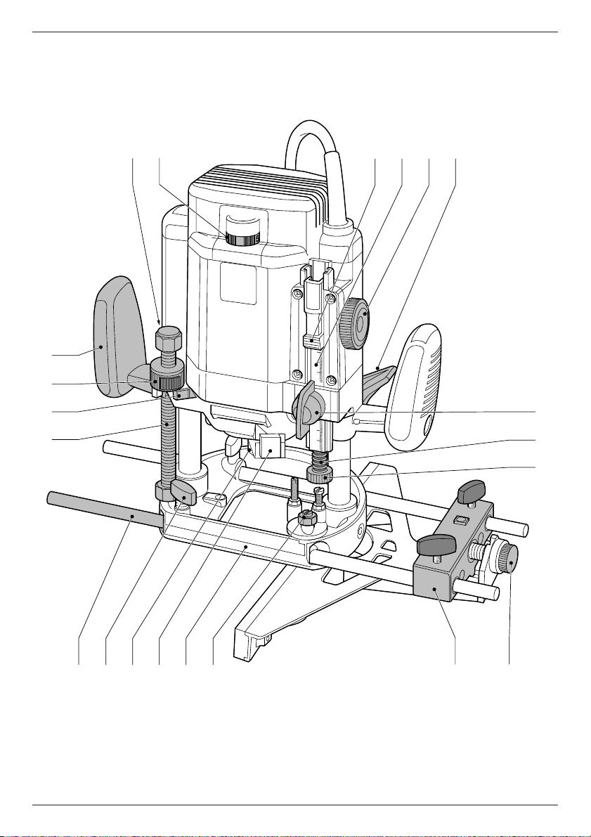
Description (fig. A)
Your DEWALT high performance Router has been
designed for professional heavy duty routing of
wood, wood products and plastics.
1 Lock-on button
2 Speed control dial
3 Collet nut
4 Spindle lock
5 Parallel fence locking bolt
6 Guide rods for parallel fence
17
7 Threaded spindle
8 Stop
9 Knurled nut
10 Grip
11 Handwheel
12 Measuring lens
13 Scale
14 Plunge lock
15 Clamping screw
16 Depth stop
17 Fine adjuster for depth stop
18 Fine adjuster for parallel fence
19 Parallel fence
20 Revolver depth stop
21 Router base
22 Baseplate extension
23 Guiding knob
Electrical safety
The electric motor has been designed for one
voltage only. Always check that the power supply
corresponds to the voltage on the rating plate.
Your DEWALT tool is double insulated
in accordance with EN 50144;
therefore no earth wire is required.
Mains plug replacement
(U.K. & Ireland only)
• Should your mains plug need replacing and you
are competent to do this, proceed as instructed
below. If you are in doubt, contact an authorized
DEWALT repair agent or a qualified electrician.
• Disconnect the plug from the supply.
• Cut off the plug and dispose of it safely; a plug
with bared copper conductors is dangerous if
engaged in a live socket outlet.
• Only fit 13 Amperes BS1363A approved plugs
fitted with the correctly rated fuse (1).
• The cable wire colours, or a letter, will be marked
at the connection points of most good quality
plugs. Attach the wires to their respective points
in the plug (see below). Brown is for Live (L) (2)
and Blue is for Neutral (N) (4).
• Before replacing the top cover of the mains plug
ensure that the cable restraint (3) is holding the
outer sheath of the cable firmly and that the two
leads are correctly fixed at the terminal screws.
en - 3
Page 8

ENGLISH
Never use a light socket.
Never connect the live (L) or neutral (N)
wires to the earth pin marked E or .
For 115 V units with a power rating exceeding 1500 W,
we recommend to fit a plug to BS4343 standard.
Using an extension cable
If an extension cable is required, use an approved
extension cable suitable for the power input of this
tool (see technical data). The minimum conductor size
is 1.5 mm2. When using a cable reel, always unwind
the cable completely. Also refer to the table below.
Assembly and adjustment
Prior to assembly and adjustment always
unplug the tool.
Inserting and removing a cutter (fig. B)
• Press and hold down the spindle lock (4).
• Using the 22 mm wrench, loosen the collet nut (3)
a few turns and insert a cutter (24).
• Tighten the collet nut and release the spindle
lock (4).
Never tighten the collet nut without
a cutter in the collet.
Replacing the collet (fig. C)
Your DEWALT Router is supplied with a 1/2" collet
fitted to the tool. Other precision collets are also
available to suit the cutter used.
• Separate the collet (25) from the collet nut (3) by
pulling it firmly.
• Click the new collet in place.
Conductor size (mm2) Cable rating (Amperes)
0.75 6
1.00 10
1.50 15
2.50 20
4.00 25
Cable length (m)
7.5 15 25 30 45 60
Voltage Amperes Cable rating (Amperes)
115 0-2.0 66 66 610
2.1 - 3.4 6 6 6 6 15 15
3.5 - 5.0 6 6 10 15 20 20
5.1 - 7.0 10 10 15 20 20 25
7.1 - 12.0 15 15 20 25 25 -
12.1 - 20.0 20 20 25 - - -
230 0 - 2.0 6 6 6 6 6 6
2.1 - 3.4 6 6 6 6 6 6
3.5 - 5.0 6 6 6 6 10 15
5.1 - 7.0 10 10 10 10 15 15
7.1 - 12.0 15 15 15 15 20 20
12.1 - 20.0 20 20 20 20 25 -
en - 4
Setting the electronic speed control dial (fig. A)
The speed is infinitely variable from 8,000 to
20,000 min-1 using the electronic speed control
dial (2) for uniform cutting results in all types
of wood and plastics.
• Turn the electronic speed control dial to the
required level. The correct setting, however,
is a matter of experience.
1 = 8,000 min
2 = 12,000 min
3 = 16,000 min
4 = 18,000 min
5 = 20,000 min
-1
-1
-1
-1
-1
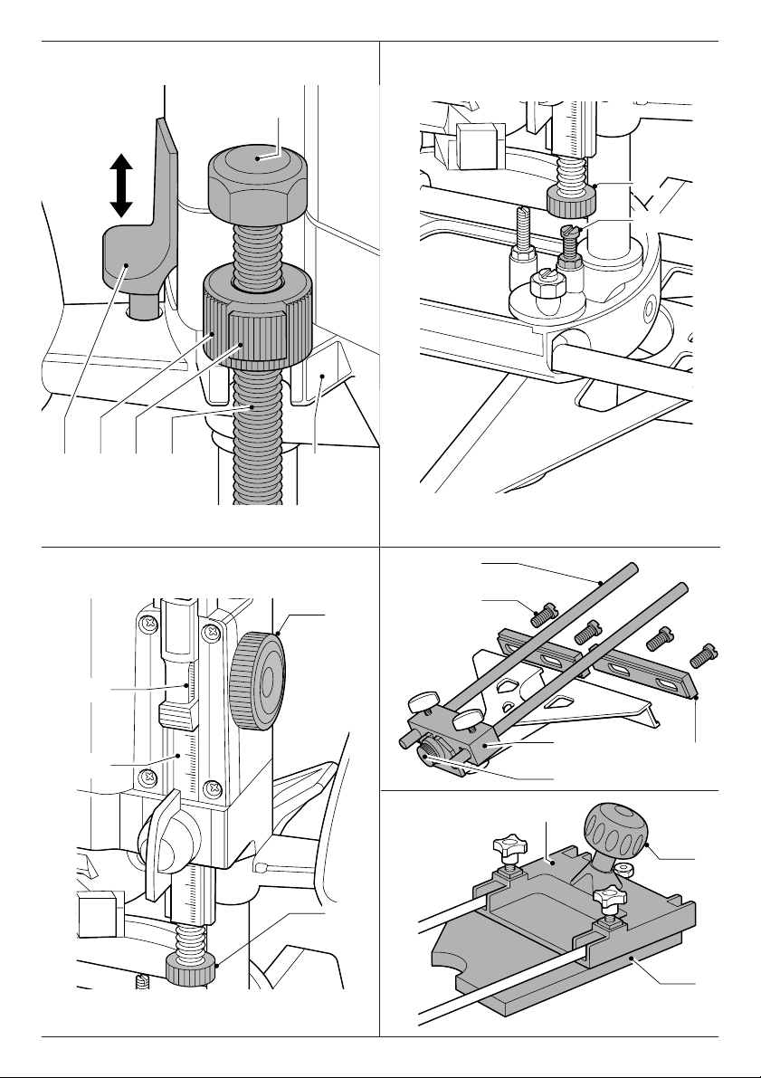
Adjusting the depth of cut (fig. A)
Your DEWALT Router is equipped with a high precision
depth adjustment system including a revolver depth
stop (20), a measuring lens (12) and fine adjuster (17).
Quick adjustment (fig. A & D)
• Loosen the plunge lock (14) by pulling it up.
• Lower the router carriage until the cutter is in
contact with the workpiece.
• Tighten the plunge lock (14) by pushing it down.
18
Page 9

ENGLISH
• For optimum ease of operation, the carriage
return can be adapted to the required depth of
cut by rotating or sliding the knurled nut (9).
• Loosen the clamping screw (15).
• Rotate the handwheel (11) until the fine adjuster
(17) touches the revolver depth stop (20).
• Set the measuring lens to a round figure (e.g. 0).
• Adjust the depth of cut using the handwheel (11)
and the measuring lens (12). The distance
between the top of the revolver depth stop and
the bottom of the fine adjuster is the adjusted
depth of cut.
• Tighten the clamping screw (15).
Triple depth adjustment using the revolver depth
stop (fig. E)
The revolver depth stop (20) can be used to set
3 different depths. This is particularly useful for deep
cuts, performed in steps.
• Place a depth template between the fine adjuster
(17) and the revolver depth stop (20) to adjust the
exact cutting depth.
• If required, set all three screws.
Make shallow cuts only!
Fine adjustment (fig. F)
When not using a depth template, or if the depth of
cut needs readjustment, it is recommended to use
the fine adjuster (17).
• Adjust the depth of cut using the fine adjuster (17).
One turn corresponds to approx. 1 mm.
• Read the depth of cut using the measuring lens (12)
and scale (13).
• Adapt the depth of cut to the millimeter using
the handwheel (11).
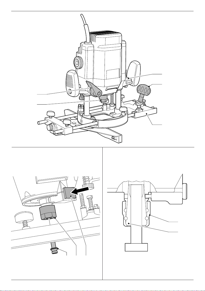
Depth adjustment with Router installed in inverted
position (fig. D)
• Remove the cap nut (27) and the knurled knob (9)
and replace it with the depth adjuster (DE6966)
available as an option.
• Connect the threaded rod of the new depth stop
to the threaded spindle (7).
• Set the depth of cut using the adjuster on the
new depth stop.
For installing the Router in inverted
position, refer to the relevant instruction
manual on the stationary tool.
Fitting the parallel fence (fig. A & G)
• Fit the guide rods (6) to the router base (21).
• Slide the parallel fence (19) over the rods.
• Tighten the locking bolts (5) temporarily.
Adjusting the parallel fence (fig. A & G)
• Draw a cutting line on the material.
• Lower the router carriage until the cutter is in
contact with the workpiece.
• Tighten the plunge lock (14) and limit the carriage
return using the knurled nut (9).
• Position the Router on the cutting line.
• Slide the parallel fence (19) against the workpiece
and tighten the locking bolts (5).
• Adjust the parallel fence using the fine adjuster (18).
The outer cutting edge of the cutter must
coincide with the cutting line.
• If required, loosen the screws (28) holding the
plastic guide strips (29) and adjust the strips to
obtain the desired guiding length.
Fitting the baseplate extension and trimming
plate (option) (fig. A & H)
When routing with large diameter cutters, it is
re-commended to fit the baseplate extension
(DE6268) (22) for secure handling. The trimming plate
(30) is used for trimming of projecting glued edges.
• Fit the baseplate extension to the free end of the
guide rods (6).
• Guide the tool with one hand on the knob (23)
and the other on the opposite grip (10).
• For trimming projecting glued edges, fit the
trimming plate (30) to the baseplate extension as
shown in figure H.
The trimming plate can be fitted directly next to the
cutter and ensures optimim guidance.
Fitting a guide bush (fig. J)
Together with a template, guide bushes (DE6430) play
a valuable part in cutting and shaping to a pattern.
• Fit the guide bush (31) to the router base (21)
using the screws (32) as shown.
19
en - 5
Page 10

ENGLISH
Connecting a dust extractor (fig. A & K)
The dust extraction adapter (33) consists of a main
section (34), a clamping piece (35), a cutter plate (36),
two screws (37) and two nuts (38).
• Slide the clamping plate (35) onto the main
section (34) from the front.
• Fit the screws (37) and nuts (38).
• Insert the cutter plate (36) from the bottom and
rotate it until it clicks in place.
• Mount the unit to the router base.
• Connect a dust extractor hose to the dust
extraction adaptor (33).
• Loosen the screw in the top of the router and fit
the hose guide as shown.
Instructions for use
• Always observe the safety instructions
and applicable regulations.
• Always move your Router as indicated in
fig. L (outer edges/inner edges).
Prior to operation:
• Check that the cutter is correctly installed in the
collet.
• Select the optimal speed using the electronic
speed control dial.
• Set the cutting depth.
• Connect a dust extractor.
• Make sure the plunge limiter is always locked
before switching ON.
Switching ON and OFF (fig. A & G)
• ON: pull the switch (1) UP.
• OFF: press the switch (1) DOWN.
If the workpiece is not thick enough,
place it on a piece of waste wood.
Guiding off a batten
Where an edge guide cannot be used, it is also
possible to guide the router along a batten clamped
across the workpiece (with an overhang at both ends).
Freehand routing
Your Router can also be used without any sort of
guide, e.g. for signwriting or creative work.
Make shallow cuts only!
Use cutters with a max. diameter of 6 mm.
Routing with pilot cutters (fig. B)
Where a parallel guide or guide bush are
inappropriate, it is possible to use pilot cutters (24)
for cutting shaped edges.
Consult your dealer for further information on the
appropriate accessories.
These include collets (1/4-1/2"), a depth stop and
router table for use in inverted position, finger
jointing tools for dovetail and finger jointing jigs,
dowel jointing templates, guide bushes (17-40 mm),
guide bushes, guide bush holders and guide rails in
various lengths.
Maintenance
Your DEWALT Power Tool has been designed to
operate over a long period of time with a minimum
of maintenance. Continuous satisfactory operation
depends upon proper tool care and regular cleaning.
Loosen the plunge limiter and allow the
router carriage to regain its rest position
before switching OFF.
Using the guide bushes (fig. J)
• Secure the template to the workpiece using end
clamps.
• Select and install an appropriate guide bush (31).
• Subtract the diameter of the cutter from the outside
diameter of the guide bush and divide by 2. This is
the difference between template and workpiece.
en - 6
Lubrication
Your Power Tool requires no additional lubrication.
Cleaning
Keep the ventilation slots clear and regularly clean
the housing with a soft cloth.
20
Page 11

GUARANTEE
ENGLISH
Unwanted tools and the environment
Take your tool to an authorized DEWALT repair
agent where it will be disposed of in an
environmentally safe way.
• 30 DAY NO RISK SATISFACTION GUARANTEE •
If you are not completely satisfied with the
performance of your DEWALT tool, simply return
it within 30 days, complete as purchased, to a
participating Dealer, or an authorized DEWALT
repair agent, for a full refund or exchange. Proof
of purchase must be produced.
• ONE YEAR FREE SERVICE CONTRACT •
If you need maintenance or service for your
DEWALT tool, in the 12 months following purchase,
it will be undertaken free of charge at an authorized
DEWALT repair agent. Proof of purchase must be
produced. Includes labour and spare parts for
Power Tools. Excludes accessories.
• ONE YEAR FULL WARRANTY •
If your DEWALT product becomes defective due
to faulty materials or workmanship within
12 months from the date of purchase, we
guarantee to replace all defective parts free of
charge or, at our discretion, replace the unit free
of charge provided that:
• The product has not been misused.
• Repairs have not been attempted by
unauthorized persons.
• Proof of purchase date is produced.
This guarantee is offered as an extra benefit
and is additional to consumers statutory rights.
For the location of your nearest authorized
DEWALT repair agent, please use the appropriate
telephone number on the back of this manual.
21
en - 7
 Loading...