

Page 1

328521-01/DW624 9/6/01 8:00 AM Page 1
1
Page 2

328521-01/DW624 9/6/01 8:00 AM Page 2
DEWALT Industrial Tool Co., 701 East Joppa Road, Baltimore, MD 21286 (DEC99) Printed in Switzerland Form No. 328521-01
DW624. DW625 Copyright © 1999
Page 3

328521-01/DW624 9/6/01 8:00 AM Page 3
INSTRUCTION MANUAL
GUIDE D’UTILISATION
INSTRUCTIVO DE OPERACIÓN, CENTROS DE SERVICIO Y PÓLIZA
DE GARANTÍA. ADVERTENCIA: LÉASE ESTE INSTRUCTIVO
ANTES DE USAR EL PRODUCTO.
MANUAL DE INSTRUCCIONES
DW624 Plunge Cut Router/DW625 Electronic Plunge Cut Router
DW624 Toupie à course plongeante/DW625 Toupie électronique à course plongeante
DW624 Rebajadora de columnas/DW625 Rebajadora electrónica de columnas
Page 4

328521-01/DW624 9/6/01 8:00 AM Page 4
IF YOU HAVE ANY QUESTIONS OR COMMENTS ABOUT
THIS, OR ANY DEWALT TOOL, CALL US TOLL FREE AT 18 0 0 - 4 - DEWALT (1-800-433-9258).
Important Safety Instructions
W A R N I N G : When using Electric Tools, basic safety precautions
should always be followed to reduce the risk of fire, electric shock,
and personal injury, including the following:
W A R N I N G : Use of this tool can generate dust containing
chemicals known to cause cancer, birth defects or other
reproductive harm. Use appropriate respiratory protection.
C A U T I O N : Some wood contains preservatives such as copper
chromium arsenate (CCA) which can be toxic. When cutting these
materials extra care should be taken to avoid inhalation and mini mize skin contact.
READ ALL INSTRUCTIONS.
• KEEP WORK AREA CLEAN. Cluttered areas and benches
invite injuries
• CONSIDER WORK AREA ENVIRONMENT. Don’t expose
power tools to rain. Don’t use power tools in damp or wet
locations. Keep work area well lit.
• GUARD AGAINST ELECTRIC SHOCK. Prevent body contact
with grounded surfaces. For example: pipes, radiators, ranges,
refrigerator enclosures.
• KEEP CHILDREN AWAY. All visitors should be kept away
from work area. Do not let visitors contact tool or extension
c o r d .
• STORE IDLE TOOLS. When not in use, tools should be
stored in dry, and high or locked-up place – out of reach of
c h i l d r e n .
• DON’T FORCE TOOL. It will do the job better and safer at the
rate for which it was intended.
• USE RIGHT TOOL. Don’t force small tool or attachment to do
the job of a heavy-duty tool. Don’t use tool for purpose not
intended, for example, don’t use circular saw for cutting tree
limbs or logs.
• DRESS PROPERLY. Do not wear loose clothing or jewelry.
They can be caught in moving parts. Non-skid footwear is
recommended when working outdoors. Wear protective hair
covering to contain long hair.
• USE SAFETY GLASSES. Also use face or dustmask if
operation is dusty.
• DON’T ABUSE CORD. Never carry tool by cord or yank it to
disconnect from receptacle. Keep cord from heat, oil, and
sharp edges.
• SECURE WORK. Use clamps or a vise to hold work. It’s safer
than using your hand and it frees both hands to operate tool.
• DON’T OVERREACH. Keep proper footing and balance at all
t i m e s .
• MAINTAIN TOOLS WITH CARE. Keep tools sharp and clean
for better and safe performance. Follow instructions for
lubricating and changing accessories. Inspect tool cords
periodically and if damaged have repaired by DeWalt certified
service center. Inspect extension cords periodically and
replace if damaged. Keep handles dry, clean, and free from oil
and grease.*
• DISCONNECT TOOLS. When not in use, before servicing,
and when changing accessories.
• REMOVE ADJUSTING KEYS AND WRENCHES. Form habit
of checking to see that keys and adjusting wrenches are
removed from tool before turning it on.
• AVOID UNINTENTIONAL STARTING. Don’t carry plugged-in
tool with finger on switch. Be sure switch is off when plugging
i n .
• EXTENSION CORDS. Make sure your extension cord is in
good condition. When using an extension cord, be sure to use
Page 5

328521-01/DW624 9/6/01 8:00 AM Page 1
one heavy enough to carry the current your product will draw.
An undersized cord will cause a drop in line voltage resulting in
loss of power and overheating. The following table shows the
correct size to use depending on cord length and nameplate
ampere rating. If in doubt, use the next heavier gage. The
smaller the gage number, the heavier the cord.
Recommended Minimum Wire Size for Extension Cords
Total Length of Cord
25 ft. 50 ft. 75 ft. 100 ft. 125 ft. 150 ft. 175 ft.
7.6 m 15.2 m 22.9 m 30.5 m 38.1 m 45.7 m 53.3 m
Wire Size
18 AWG 18 AWG 16 AWG 16 AWG 14 AWG 14 AWG 2 AWG
• OUTDOOR USE EXTENSION CORDS. When tool is used
outdoors, use only extension cords intended for use outdoors
and so marked.
• STAY ALERT. Watch what you are doing. Use common sense.
Do not operate tool when you are tired.
• CHECK DAMAGED PARTS. Before further use of the tool, a
guard or other part that is damaged should be carefully checked
to determine that it will operate properly and perform its
intended function. Check for alignment of moving parts, binding
of moving parts, breakage of parts, mounting, and any other
conditions that may affect its operation. A guard or other part
that is damaged should be properly repaired or replaced by a
DEWA L T certified service center unless otherwise indicated
elsewhere in this instruction manual. Have defective switches
replaced by a DEWA L T certified service center. Do not use tool
if switch does not turn it on and off.
• DO NOT OPERATE portable electric tools near flammable
liquids or in gaseous or explosive atmospheres. Motors in these
tools normally spark, and the sparks might ignite fumes.
SAVE THESE INSTRUCTIONS
FOR FUTURE USE.
Double Insulation
DOUBLE-INSULATED tools are constructed throughout with TWO
separate “layers” of electrical insulation between you and the tool’s
electrical system.
Tools built with this insulation system are not intended to be
grounded. As a result, your tool is equipped with a two-prong plug
which permits you to use extension cords without concern for
maintaining a ground connection.
N O T E : DOUBLE INSULATION does not take the place of normal
safety precautions when operating this tool. The insulation system is
for added protection against injury resulting from a possible
electrical insulation failure within the tool.
CAUTION: When servicing all tools, USE ONLY IDENTICAL
Polarized Plugs
Polarized plugs (one blade is wider than the other) are used on
equipment to reduce the risk of electric shock. When provided,
this plug will fit into a polarized outlet only one way. If the plug
does not fit fully into the outlet, reverse the plug. If it still does not
fit, contact a qualified electrician to install the proper outlet. Do not
change the plug in any way. REPLACEMENT PARTS. Repair or
replace damaged cords.
Motor
Your DEWA L T tool is powered by a DEWA L T-built motor. Be sure
your power supply agrees with the nameplate marking.
Volts 50/60 Hz or “AC only” means your tool must be operated only
with alternating current and n e v e r with direct current. Volts DC60Hz or AC/DC means your tool may be operated with either
alternating or direct current.
1
Page 6
328521-01/DW624 9/6/01 8:00 AM Page 2
Voltage decrease of more than 10% will cause loss of power and
overheating. All DeWalt tools are factory tested; if this tool does not
operate, check the power supply.
Additional Specific Instructions for
Routers
The electronic motor control system has two basic features.
A. Soft start - when you turn on the router, you will notice that it
does not have the jerk from the rapid acceleration of the motor.
This router has a starting circuit which accelerates the motor up to
speed smoothly, without jerking, and allows you to maintain easier
control of the router during the start up period.
B. Constant speed cutting - as you load the router, the selected
cutting speed does not slow down during normal use. The
electronic control governs the motor and gives you a consistent
finish to your work. Only under very heavy loading will the speed of
the unit fall below the governed speed.
To set the router speed (from 8,000 rpm to 20,000 rpm) rotate the
speed control wheel shown in the large figure on page 2. The
higher the number the higher the speed. Consult TABLE 1 (page 3)
to help select the proper speed for your application.
Specifications
PREPARATION FOR USE
The motor in this router is high-powered (750 Watts, max.). Despite
this, it is advisable to cut deep grooves or remove large amounts of
material in two or more passes.
Operating Instructions
TURN OFF AND UNPLUG ROUTER
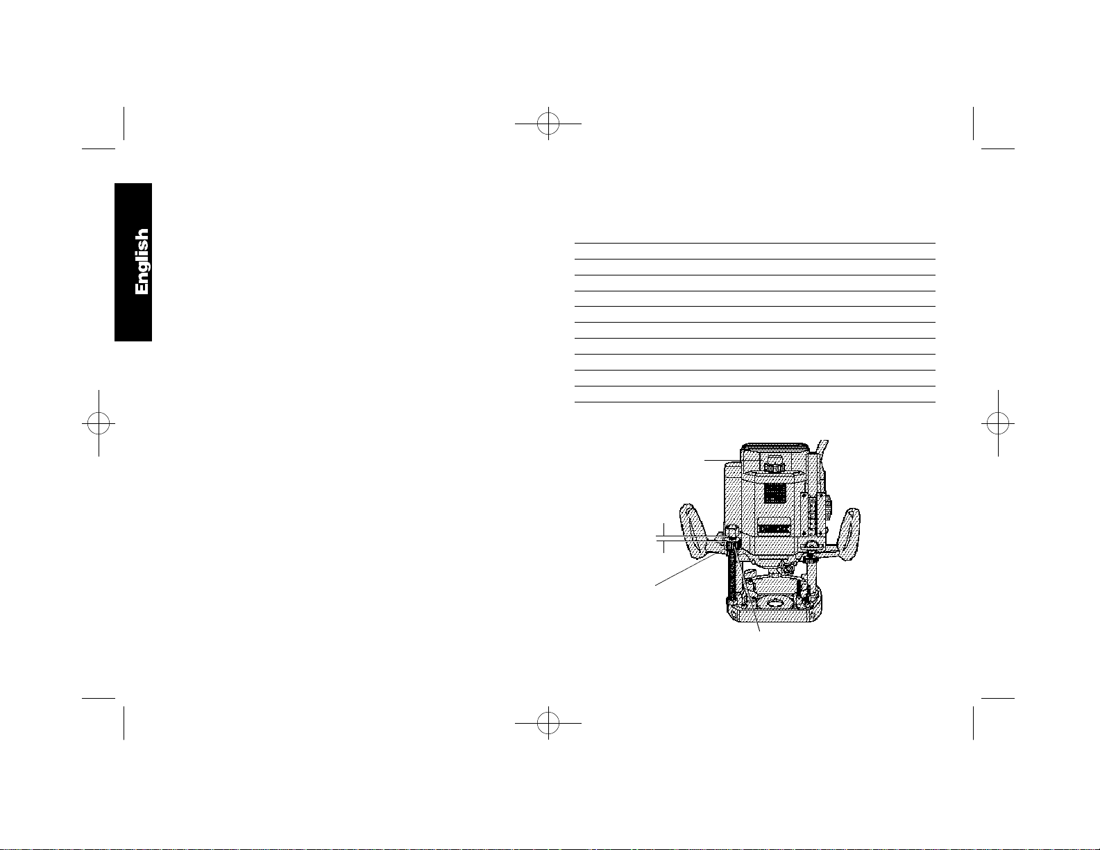
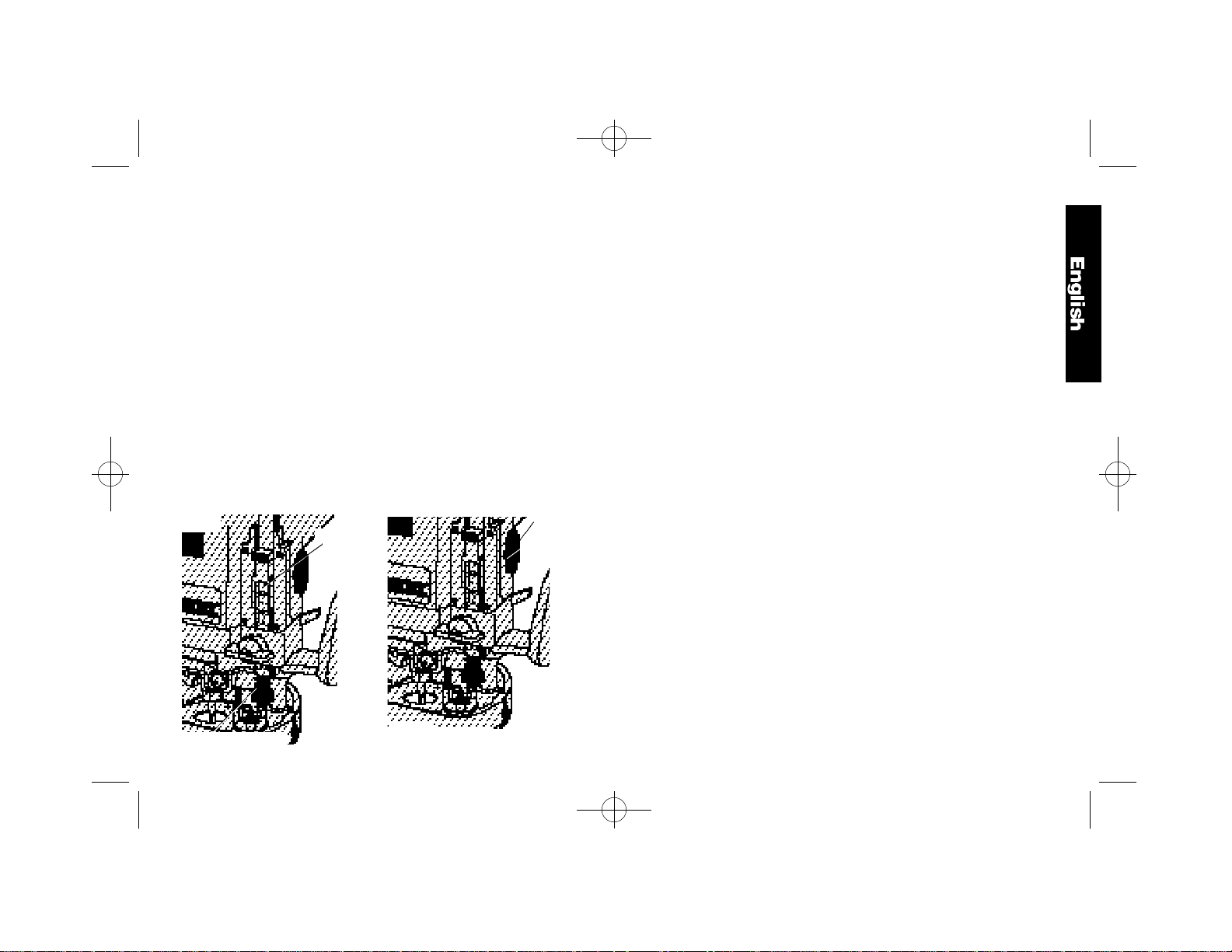
N O T E : Before installing a router bit in your unit, position the tool so
that the collet is easily accessible. To do this, rotate the height stop
thumb wheel, shown in Figure 1, counterclockwise until it is about
1/2” from the top of the threaded height stop rod. Raise the plunge
release lever, shown in Figure 2, and let the router rise to its full
height. Depress the plunge release lever to lock the tool in place.
TECHNICAL DATA
M o d e l DW624, DW625
V o l t a g e 1 2 0
Speed DW624 20,000 r.p.m.
Speed DW625 8,000- 20,000 r.p.m.
I n s u l a t i o n double insulated
C o l u m n spring loaded twin column
Plunging stroke 70mm (2-3/4”)
Routing depth 0-70 mm adjustable
Cutter mounting precision collet, size 1/2”-1/4”
Cutter cap max. 63.5 mm (2-1/2")
R o u t i n g (shallow)
Rotary depth stop 3 stage depth position
FIG. 1
2
SPEED
CONTROL
WHEEL
1/2
QUICK
RELEASE
BUTTON
HEIGHT STOP THUMB
WHEEL
Page 7
328521-01/DW624 9/6/01 8:00 AM Page 3
SPEED SELECTION CHART
TABLE 1: RECOMMENDATION FOR THE CORRECT CHOICE OF SPEED
Material Cutter Diam. Electronic Control Settings
Stage 1 Stage 2 Stage 3 Stage 4 Stage 5
Model #DW624/DW625 8,000 rpm 12,000 rpm 16,000 rpm 18,000 rpm 20,000 rpm
Hardwood, e.g., oak Small (1/2") – – O X XX
Medium (1/2"-1 1/8") – – O XX X
Large (over-1 1/8") X XX O – –
Softwood, e.g., pine Small (1/2") – – O X XX
Medium (1/2"-1 1/8") – O X XX XX
Large (over-1 1/8") X XX O O –
Plastic-laminated chipboard Small (1/2") – – O X XX
Medium (1/2"-1 1/8") – O X XX XX
Large (over-1 1/8") O XX X O –
Plastics Small (1/2") – O X X XX
Medium (1/2"-1 1/8") – O XX XX X
Large (over-1 1/8") X XX O – –
This Table can serve only as a guide, since wood is a living material. Even with the same species of timber there will be large differences in
hardness and density. When a high speed is employed, set the electronic control one step higher.
KEY: XX very good X good O Satisfactory – not recommended
3
Page 8

328521-01/DW624 9/6/01 8:00 AM Page 4
Switch
TO SWITCH ON THE MACHINE
N O T E : Always pull the plug on the cord set out of its receptacle
when changing a cutter or fitting the accessories in order to avoid
any chance of an accident.
CONVENIENT SWITCH ACTUATOR PUSH UP FOR “ON”
DOWN FOR “OFF”.
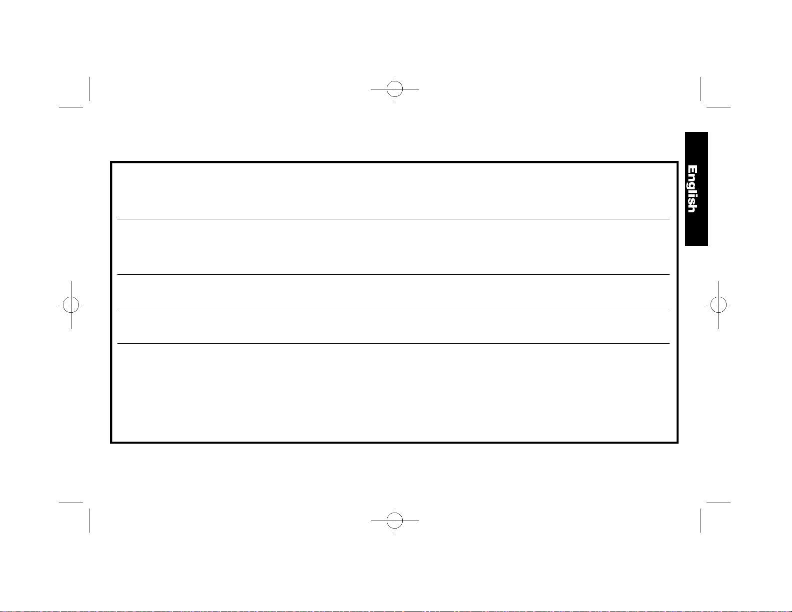
Bit Installation and Removal
(TURN OFF AND UNPLUG ROUTER)
IMPORTANT NOTE: Always snap the collet firmly into the collet
nut, (past the retainer spring) before installing a bit.
Use the supplied wrench and the spindle lock as necessary to
loosen (counterclockwise) the collet nut, as shown in Figure 3.
Insert the round shank of the desired router bit into the loosened
collet as far as it will go and then pull it out about 1/16”. Hold the
spindle shaft by depressing the spindle lock button, shown in
Figure 3, while firmly tightening the collet nut with the wrench
p r o v i d e d .
Your router has a unique locking system for retaining the bit.
When removing a bit, the collet nut must be loosened with the
wrench. The collet nut will turn approximately 3/4 of a turn and
then become tight again. At this point the bit can’t be removed.
Using the same procedure, loosen the nut a second time.This lifts
the collet and makes it very easy to remove the bit.
Collets
NEVER TIGHTEN THE COLLET ON THIS TOOL WITHOUT
FIRST INSTALLING A ROUTER BIT IN IT. TIGHTENING AN
EMPTY COLLET CAN DAMAGE THE COLLET.
To change collets, unscrew the collet assembly, as described
above, sharply pull the old collet out of the collet nut and insert the
new collet. Push firmly so that it snaps past the retainer spring in
the collet nut.
Controls
N O T E : Before operating any of the controls, read this whole
s e c t i o n .
PLUNGE RELEASE LEVER
The plunge release lever allows the router bit to be plunged
directly into the workpiece. Simply raise the plunge release lever
when you want to lower the router into the work, as shown in
Figure 2. You can lower the unit until it reaches your preset stop.
To lock the tool in place anywhere along its vertical travel, depress
the lever.
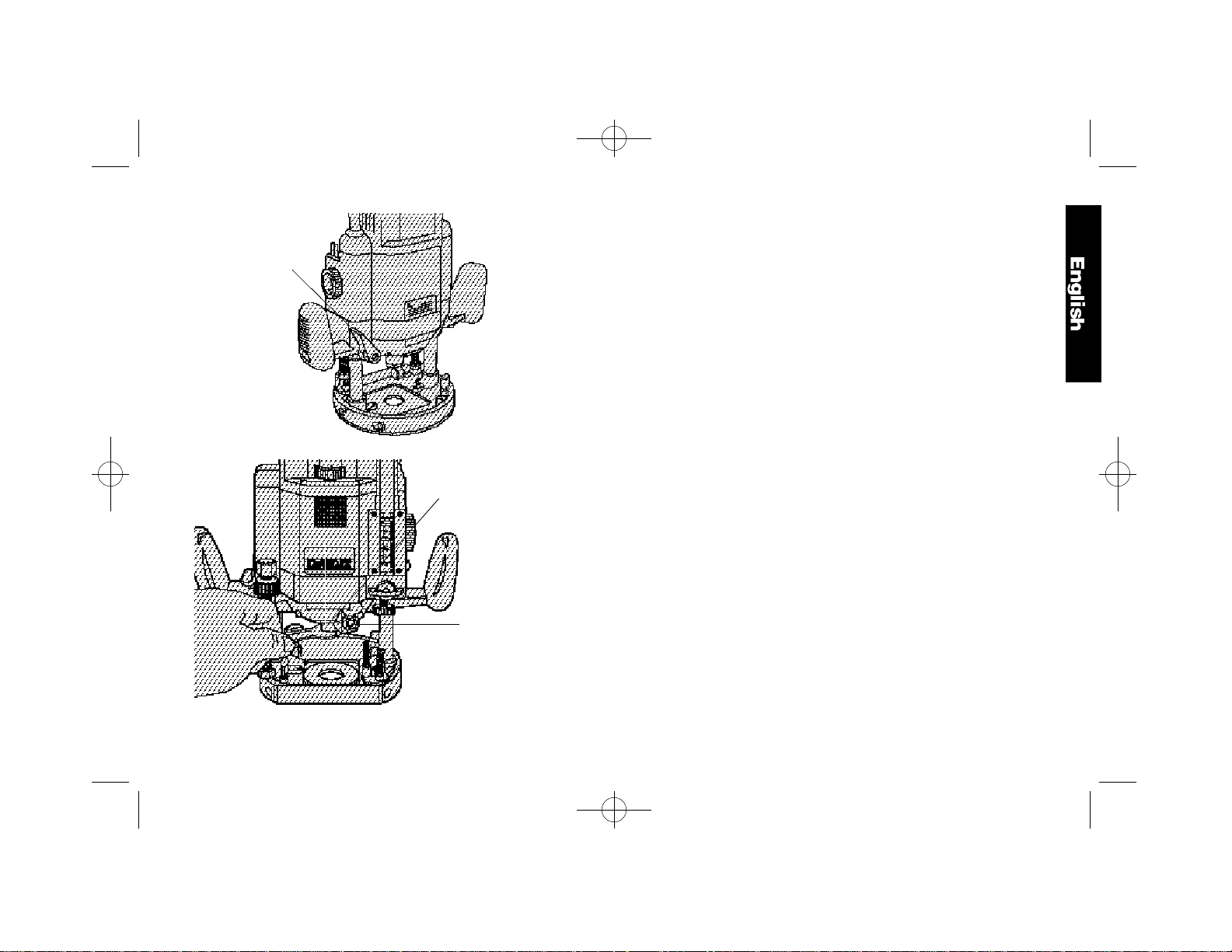
HEIGHT STOP ROD AND HEIGHT STOP THUMB WHEEL
As its name implies, the height stop rod and thumb wheel limit how
high the unit can travel up the rails. The system is adjustable from
full down where the unit cannot rise regardless of the position of
the plunge release lever to full up where the bottom of the collet is
2-7/8” above the workpiece (See Figure 4).
For convenience, the thumb wheel is equipped with a quick
release button that allows you to disengage the threads for fast
positioning by simply depressing the button in the side of the
w h e e l .
NOTE: It is easier to move the height stop thumb wheel UP if the
plunge release lever is locked and easier to move the thumb wheel
DOWN if the unit is first moved down by releasing the plunge
release lever and then tightening it.
MULTI-POSITION TURRET STOP
The turret stop limits the downward distance that the tool can be
plunged. It consists of three screws of different lengths that serve
to define the depth of cut by limiting the travel of the depth stop bar
(see Figure 5). Routing depth can be set by selecting the screw of
the appropriate length on the turret. The turret is rotatable with
detent stops to properly align the screws.
It is the interaction of the depth stop bar and the turret stop that
4
Page 9
328521-01/DW624 9/6/01 8:00 AM Page 5
PLUNGE
RELEASE
LEVER
COLLET NUT
SPINDLE LOCK
BUTTON
FIG. 2
FIG. 3
determine the routing depth.
If none of the provided screws seems close to the desired height
each can be adjusted by loosening the hex nut at the bottom and
then turning the screw either in or out to make it the proper length.
After adjusting this screw be sure to tighten the hex nut at the
bottom. (See Figure 6)
See the section “Setting the Routing Depth” for instructions on
how to use the turret stop in an actual operation.
DEPTH STOP BAR AND VERNIER
The depth stop bar is what contacts the selected screw in the
turret stop to limit the routing depth. At the bottom of the depth
stop bar is a threaded shaft, a spring and a knurled knob, as
shown in Figure 7.
A precision vernier scale is provided for extremely accurate
adjustment of the routing depth.
See the section below “Setting the Routing Depth” for instructions
on how to use the depth stop bar and vernier in an actual
o p e r a t i o n .
Familiarization
Please take a little time now and, without plugging the tool in,
practice with these adjustments and controls and become familiar
with their operation. Only with a complete, “hands on”
understanding of these systems will you be able to get the most
out of this quality router.
Setting the Routing Depth
(TURN OFF AND UNPLUG THE ROUTER)
To set the routing depth follow the steps below:
1 . Install the desired router bit as described previously.
2 . Position the height stop thumb wheel at the top of the height
stop rod. (See Figure 4) You can either turn the thumb wheel
or use the handy quick release button discussed above.
3 . Adjust the depth stop bar to the top of its travel by rotating the
5
Page 10
328521-01/DW624 9/6/01 8:00 AM Page 6
Depth Stop Control Knob shown in Figure 9.
4 . Rotate the turret stop to position the shortest screw under the
depth stop bar.
5 . Raise the plunge release lever and push the router down until
the end of the bit just touches the workpiece.
6 . Lower the depth stop bar until the knurled knob on the bottom
of it touches the selected screw in the turret stop.
7 . Raise or lower the plastic vernier to align the hairline in the
vernier with the 0 mark on the graduated scale, as shown in
Figure 8.
8 . Using the depth stop control knob, raise the depth stop bar and
align the desired mark on the graduated scale with the hairline
in the vernier, as shown in Figure 9. (Scale graduated in
1/16ths of an inch)
9 . Tighten the depth stop bar clamp.
10.The router is now set to cut to the set depth when plunged into
the workpiece.
Fine Adjustment of Routing Depth
TURN OFF AND UNPLUG ROUTER.
If, after setting the desired depth of cut, a small adjustment is
needed, it is not necessary to go through the entire procedure for
setting the depth. Minor adjustment can be easily made by
rotating the knurled knob on the bottom end of the depth stop bar,
as shown in Figure 8.
Rotating the knob clockwise (looking down from the top of the
router) will result in a more shallow cut. Rotating the knob
counterclockwise will result in a deeper cut. One complete rotation
of the knob represents about 1 mm in depth adjustment.
FIG. 4
HEIGHT STOP
THUMB
WHEEL
FIG. 6
BOTTOM OF
COLLET
HEIGHT
STOP
ROD
FIG. 5
DEPTH
STOP
TURRET
STOP
QUICK
RELEASE
BUTTON
FIG. 7
DEPTH
STOP BAR
VERNIER
6
TURRET STOP
KNURLED
KNOB
SPRING
Page 11
328521-01/DW624 9/6/01 8:00 AM Page 7
Using the Turret Stop for Sequential
Routing Depth Settings
TURN OFF AND UNPLUG ROUTER.
It is recommended that particularly deep grooves be cut with
several passes rather than one deep pass. In order to do this and
still maintain accuracy of depth when the job is finished, perform
the following procedure.
1 . Set the final desired routing depth as instructed above. For
the purpose of this discussion, assume that the desired
depth is 1/2”.
2 . With a depth of 1/2” set on the shortest screw in the turret
stop, adjust the second shortest screw to a point about
halfway between the bottom of the knurled knob and the top
of the shortest screw, as shown in Figure 10.
3 . Leave the vernier setting alone and turn the adjusted second
shortest screw into position under the depth stop bar.
4 . Make your first cut at this setting.
FIG. 8
KNURLED KNOB
HAIRLINE
FIG. 9
DEPTH
STOP
CONTROL
KNOB
5 . Rotate the turret stop so that the shortest screw is directly
under the depth stop bar and make your final cut.
N O T E : The third screw in the turret stop is provided if your cut is
even deeper and you want to make three cuts to achieve the final
depth, or set final depth for multiple cuts at one time.
Operation
After setting the cutting depth as described, locate the router such
that the bit is directly over the place you will be cutting. With the
router running, lower the unit smoothly down into the workpiece.
(DO NOT JAM THE ROUTER DOWN). When the tool reaches
the pre-set depth, depress the Plunge Lock Lever. When you
have finished routing, raise the lever and let the spring lift the
router directly out of the workpiece.
All common routing tasks can be performed with ease with the
Plunge Cut Router: Grooving, rabbeting, recessing, veining, and
profiling on all types of wood and plastic.
Always feed the router opposite to the direction in which the cutter
is rotating.
Only carbide-tipped cutters should be used on panels faced with
plastic laminates. The hard laminates will quickly dull steel cutters.
Your DeWalt certified Service center has a Router Craft Handbook
available at extra cost which covers the use of routers in great
detail and shows the various types of bits available.
Direction Of Feed (Fig. 12)
The direction of feed is very important when routing and can make
the difference between a successful job and a ruined project.
Figures 11 and 12 show proper direction of feed for some typical
c u t s .
Mold the outside edge of a piece of stock by a) mold the end
grain, left to right, b) do the straight grain side moving left to right,
c) finish the other end grain side, and d) do the remaining straight
grain edge.
7
Page 12

328521-01/DW624 9/6/01 8:00 AM Page 8
The direction of feed is important in router usage. Be sure the
cutter is rotating into the stock by moving left to right on outside
edges and clockwise on inside cuts.
Using the Parallel Guide (Fig. 15)
A parallel guide, available at extra cost, router will increase the
versatility of your router. Assemble the guide as shown in Figure
18. When it’s fully assembled, insert the two bars through the
holes in the router base as shown in Figure 19. Adjust as needed
for parallel routing.
The guide will adjust in all the way to the cutter. In some cases
the plastic slides on the guide will interfere with the cutter if they
are not loosened and pushed back to provide clearance. Simply
loosen the two screws on each slide and adjust it accordingly.
A fine adjust feature is included on the parallel guide and is
operated by rotating the fine adjust knob, shown in Figure 14.
Turn the knob clockwise to move the guide in (closer to the bit).
Turn the knob counterclockwise to move the guide out (away from
the bit).
FIG.10
FIG. 11
C
FIG. 14
FIG. 12
B
A
D
FIG. 13
ROUTER USING TEMPLATE
AND GUIDE BUSHING
FIG. 15
SHORTEST SCREW
TURRET STOP
FINE ADJUST KNOB
8
Page 13

328521-01/DW624 9/6/01 8:00 AM Page 9
FIG. 16
C
B
A
Template Guide Adapter
Your router comes equipped with a template guide adapter and two
mounting screws. Put these away in a safe place for future use.
Connecting a Dust Extractor (Fig 16)
The dust extractor adapter consists of the body (A), the cover (B),
and the hose guide (C). Assemble as follows:
1 . Side the cover onto the main body and let it click into place.
2 . Connect a dust extractor hose to the outlet.
3 . Loosen the screw on the top cover of the router and secure the
hose guide in place.
Accessories
If you need assistance in locating any accessory, please contact
DEWALT Industrial Tool Co., 701 East Joppa Road, Baltimore,
MD 21286 or call 1-800-4-DEWALT (1-800-433-9258).
CAUTION: The use of any other accessory might be
hazardous.
Important
To assure product SAFETY and RELIABILITY, repairs,
maintenance and adjustment (including brush inspection and
replacement) should be performed by authorized service centers
or other qualified service organizations, always using identical
replacement parts.
Full Wa rr a n t y
DEWALT heavy duty industrial tools are warranted for one year
from date of purchase. We will repair, without charge, any
defects due to faulty materials or workmanship. For warranty
repair information, call 1-800-4-DEWALT. This warranty does not
apply to accessories or damage caused where repairs have
been made or attempted by others. This warranty gives you
specific legal rights and you may have other rights which vary in
certain states or provinces.
In addition to the warranty, DEWALT tools are covered by our:
30 DAY NO RISK SATISFACTION GUARANTEE
If you are not completely satisfied with the performance of your
DEWA L T heavy duty industrial tool, simply return it to the
participating seller within 30 days for a full refund. Please return
the complete unit, transportation prepaid. Proof of purchase may
be required.
9
Page 14

328521-01/DW624 9/6/01 8:00 AM Page 10
POUR TOUT RENSEIGNEMENT SUPPLÉMENTAIRE SUR CET
OUTIL OU TOUT AUTRE OUTIL DEWALT, COMPOSER SANS
FRAIS LE NUMÉRO :
1 800 4-DEWALT (1-800-433-9258)
Importantes mesures de sécurité
AVERTISSEMENT : Afin de réduire les risques d'incendie, de
secousses électriques ou de blessures lorsqu'on utilise un outil électrique,
il faut toujours respecter certaines règles de sécurité fondamentales,
notamment les suivantes.
AVERTISSEMENT :L’utilisation de l’outil peut générer des
poussières renfermant des produits chimiques qui peuvent causer
le cancer, des malformations congénitales ou autre maladie
congénitale. Se servir des appareils respiratoires protecteurs
a p p r o p r i é s .
MISE EN GARDE : Certaines essences de bois renferment des
agents de conservation (comme de l'arséniate de cuivre et de
chrome) qui peuvent être toxiques. Lorsqu'on doit couper de tels
matériaux, prendre des mesures supplémentaires afin d'éviter
d'inhaler les vapeurs toxiques et de minimiser les contacts avec la
peau.
LIRE TOUTES LES DIRECTIVES.
• BIEN DÉGAGER LA SURFACE DE TRAVAIL. Des surfaces et des
établis encombrés peuvent être la cause de blessures.
• TENIR COMPTE DU MILIEU DE TRAVAIL. Protéger les outils
électriques de la pluie. Ne pas s'en servir dans des endroits humides
ou mouillés. Bien éclairer la surface de travail.
• SE PROTÉGER CONTRE LES SECOUSSES ÉLECTRIQUES. É v i t e r
tout contact avec des objets mis à la terre, comme des tuyaux,
radiateurs, cuisinières, réfrigérateurs et autres objets du genre.
• ÉLOIGNER LES ENFANTS. Tous les visiteurs doivent être tenus à
l'écart de l'aire de travail et il faut les empêcher de toucher à l'outil ou
au cordon de rallonge.
• RANGER LES OUTILS INUTILISÉS. Il faut ranger les outils dans un
endroit sec, situé en hauteur ou fermé à clé, hors de la portée des
e n f a n t s .
• NE JAMAIS FORCER L'OUTIL. Afin d'obtenir un rendement sûr et
efficace, utiliser l'outil à son rendement nominal.
• UTILISER L'OUTIL APPROPRIÉ. Ne jamais exiger d'un petit outil ou
d'un accessoire le rendement d'un outil de fabrication plus robuste. Se
servir de l'outil selon l'usage prévu (par exemple, ne pas se servir d'une
scie circulaire pour couper des branches d'arbres ou des bûches).
• PORTER DES VÊTEMENTS APPROPRIÉS. Éviter de porter des
vêtements amples et des bijoux qui peuvent être happés par les pièces
en mouvement. Porter des chaussures à semelle antidérapante pour
travailler à l'extérieur. Protéger la chevelure si elle est longue.
• PORTER DES LUNETTES DE SÉCURITÉ. Porter également un
masque respiratoire si le travail de coupe produit de la poussière.
• NE PAS MANIPULER LE CORDON DE FAÇON ABUSIVE. Ne pas
transporter l'outil par le cordon ni tirer sur ce dernier pour le débrancher
de la prise. Éloigner le cordon des sources de chaleur, des flaques
d'huile et des arêtes tranchantes.
• ASSUJETTIR LA PIÈCE. Immobiliser la pièce à l'aide de brides ou d'un
étau. On peut alors se servir des deux mains pour faire fonctionner l'outil,
ce qui est plus sûr.
• NE PAS DÉPASSER SA PORTÉE. Toujours demeurer dans une
position stable et garder son équilibre.
• PRENDRE SOIN DES OUTILS. Conserver les outils propres et affûtés
pour qu'ils donnent un rendement supérieur et sûr. Suivre les directives
concernant la lubrification et le remplacement des accessoires. Inspecter
régulièrement le cordon de l'outil et le faire réparer au besoin à un atelier
d'entretien DeWalt autorisé. Inspecter régulièrement les cordons de
rallonge et les remplacer lorsqu'ils sont endommagés. S'assurer que les
poignées sont toujours propres, sèches et libres de toute tache d'huile ou
de graisse.
• DÉBRANCHER LES OUTILS NON UTILISÉS. Respecter cette mesure
lorsqu'on ne se sert pas de l'outil, ou qu'on doit le réparer ou en changer
un accessoire.
• ENLEVER LES CLÉS DE RÉGLAGE. Prendre l'habitude de vérifier si
10
Page 15

328521-01/DW624 9/6/01 8:00 AM Page 11
les clés de réglage ont été retirées avant de faire démarrer l'outil.
• ÉVITER LES DÉMARRAGES ACCIDENTELS. Ne pas laisser le doigt
sur l'interrupteur lorsqu'on transporte l'outil. S'assurer que l'interrupteur
est à la position hors circuit lorsqu'on branche l'outil.
• CORDONS DE RALLONGE. S'assurer que le cordon de rallonge est en
bon état. Lorsqu'on se sert d'un cordon de rallonge, s'assurer qu'il est de
calibre approprié pour la tension nécessaire au fonctionnement de l'outil.
L'utilisation d'un cordon de calibre inférieur occasionne une baisse de
tension entraînant une perte de puissance et la surchauffe. Le tableau
suivant indique le calibre approprié selon la longueur du cordon et les
mentions de la plaque signalétique de l'outil. En cas de doute, utiliser un
cordon de calibre supérieur. Le chiffre indiquant le calibre est
inversement proportionnel au calibre du cordon.
Calibre minimal recommandé pour les cordons de rallonge
Longueur totale du cordon
25 pi 50 pi 75 pi 100 pi 125 pi 150 pi 175 pi
7,6 m 15,2 m 22,9 m 30,5 m 38,1 m 45,7 m 53,3 m
Calibre de fil
18 AWG 18 AWG 16 AWG 16 AWG 14 AWG 14 AWG 12 AWG
• CORDONS DE RALLONGE PRÉVUS POUR L'EXTÉRIEUR. L o r s q u e
l'outil est utilisé à l'extérieur, ne se servir que d'un cordon de rallonge
conçu pour l'extérieur et portant la mention appropriée.
• DEMEURER VIGILANT. Travailler avec vigilance et faire preuve de bon
sens. Ne pas se servir de l'outil lorsqu'on est fatigué.
• VÉRIFIER LES PIÈCES ENDOMMAGÉES. Avant de continuer à utiliser
l'outil, il faut vérifier si le protecteur ou toute autre pièce endommagée
remplit bien la fonction pour laquelle il a été prévu. Vérifier l'alignement
et les attaches des pièces mobiles, le degré d'usure des pièces et leur
montage, ainsi que tout autre facteur susceptible de nuire au bon
fonctionnement de l'outil. Faire réparer ou remplacer toute pièce ou tout
protecteur endommagé dans un centre de service DEWA L T autorisé, sauf
si le présent guide fait mention d'un avis contraire. Confier le
remplacement de tout interrupteur défectueux à un centre de service
DEWA L T autorisé. Ne jamais se servir d'un outil dont l'interrupteur est
d é f e c t u e u x .
• NE PAS UTILISER les outils portatifs électriques dans des endroits où
l'atmosphère contient des vapeurs combustibles ou explosives. Les
étincelles que produit le moteur en marche pourraient enflammer ces
p r o d u i t s .
CONSERVER CES MESURES À
TITRE DE RÉFÉRENCE.
Double isolation
Les outils à DOUBLE ISOLATION comportent DEUX couches
distinctes d'isolant électrique qui protègent l'utilisateur contre les
risques de blessures provenant du système électrique de l'outil
Ce système de double isolation élimine le besoin de mettre les outils
à la terre. En effet, l'outil est muni d'une fiche à deux broches, ce qui
permet d'utiliser une rallonge ordinaire sans avoir à se soucier
d'assurer la mise à la terre.
NOTE : La DOUBLE ISOLATION ne dispense pas des mesures de
sécurité normales lors de l'utilisation de l'outil. Elle vise à procurer
une protection supplémentaire contre les blessures que peut
entraîner une défectuosité de l'isolant électrique à l'intérieur de l'outil.
MISE EN GARDE : LORS DE L'ENTRETIEN, N'UTILISER QUE
DES PIÈCES DE RECHANGE IDENTIQUES. Réparer ou remplacer
les cordons endommagés.
Fiche polarisée
Afin de réduire les risques de secousses électriques, l’outil est muni
d’une fiche polarisée (une lame plus large que l’autre). Ce genre
de fiche n’entre que d’une façon dans une prise polarisée.
Lorsqu’on ne peut insérer la fiche à fond dans la prise, il faut tenter
de le faire après avoir inversé les lames de côté. Si la fiche n’entre
toujours pas dans la prise, il faut communiquer avec un électricien
certifié. Il ne faut pas modifier la fiche.
11
Page 16

328521-01/DW624 9/6/01 8:00 AM Page 12
Moteur
La toupie DeWALT est actionnée par un moteur DEWALT. Veiller à
ce que la tension d'alimentation soit conforme aux exigences de la
plaque signalétique de l'outil.
La mention «volts 50 ou 60 Hz» ou « c.a. seulement» signifie qu'il
faut utiliser du courant alternatif seulement, jamais du courant
continu. La mention «volts c.c. 60 Hz» ou « c.a./c.c.» signifie qu'on
peut utiliser du courant alternatif ou du courant continu.
Une baisse de tension de plus de 10 p. 100 entraîne une perte de
puissance et la surchauffe. Tous les outils DEWALT sont essayés
avant de quitter l'usine. Lorsque celui-ci refuse de fonctionner,
vérifier la source de courant électrique.
Directives particulières aux toupies
La commande électronique du moteur consiste en deux fonctions de
b a s e .
A. Démarrage en douceur - Lorsqu'on met la toupie en marche, il
n'y a pas de coups en raison de l'accélération rapide du moteur. Le
circuit de démarrage de la toupie fait accélérer doucement le moteur
jusqu'à l'obtention de la vitesse requise, sans donner de coups, ce
qui facilite la maîtrise de l'outil au démarrage.
B. Régime constant - Lorsque la toupie fonctionne, elle ne ralentit
pas sous la charge dans des conditions d'utilisation normales. La
commande électronique régit le moteur et assure une finition
uniforme du travail. La vitesse de l'outil diminue seulement sous des
conditions d'utilisation très dures.
Pour régler la vitesse de la toupie (de 8 000 à 22 000 trs/min), faire
tourner la tête moletée du contrôle de la vitesse illustrée sur la
grande figure de la page 2. Plus le chiffre indiqué est élevé, plus la
vitesse de l'outil est élevée. Consulter le tableau 1 (page 13) afin de
déterminer la bonne vitesse pour l'utilisation de la toupie.
Fiche technique
PRÉPARATION EN VUE DE L'UTILISATION
Le moteur de la toupie est très puissant (750 watts max.). Il est
toutefois recommandé de faire au moins deux passes pour découper
des rainures profondes ou pour enlever une importante quantité de
m a t é r i a u .
Directives relatives au fonctionnement
METTRE LA TOUPIE HORS CIRCUIT ET LA DÉBRANCHER.
NOTE : Pour installer une mèche, il faut d'abord déposer l'outil de
façon à accéder facilement au porte-mèche. Pour y arriver, faire
tourner le limiteur de course à tête moletée (fig. 1) dans le sens
antihoraire sur environ 1/2 po à partir du haut de la tige filetée du
limiteur. Soulever le levier de dégagement de la course plongeante
(fig. 2) et laisser monter la toupie au maximum. Abaisser le levier de
dégagement de la course plongeante afin de verrouiller l'outil en
p l a c e .
DONNÉES TECHNIQUES
M o d è l e DW624, DW625
T e n s i o n 120 volts
Vitesse DW624 20 000 trs/min
Vitesse DW625 De 8 000 à 20 000 trs/min
I s o l a t i o n D o u b l e
C o l o n n e Double à ressort
Course plongeante 70 mm (2 3/4 po)
Profondeur de coupe De 0 à 70 mm, réglable
Installation de la mèche Porte-mèche de précision, de 1/2
po à 1/4 po
M è c h e 63,5 mm max. (2 1/2 po)
T o u p i l l a g e (peu profond)
Limiteur de profondeur rotatif À trois positions
12
Page 17

328521-01/DW624 9/6/01 8:00 AM Page 13
TABLEAU DU CHOIX DE VITESSE
TABLEAU 1 : VITESSE RECOMMANDÉE
Diam. de la mècheRéglage de la commande électronique
Matériau Niveau 1 Niveau 2 Niveau 3 Niveau 4 Niveau 5
Modèles DW624 et DW625 8 000 trs/min12 000 trs/min16 000 trs/min 18 000 trs/min 20 000 trs/min
Feuillus (chêne, p. ex.)
Petite (1/2 po) – – O X XX
Moyenne (de 1/2 po à 1 1/8 po) – – O XX X
Large (plus de 1 1/8 po) X XX O – –
Résineux (pin, p. ex.)
Petite (1/2 po) – – O X XX
Moyenne (de 1/2 po à 1 1/8 po) – O X XX XX
Large (plus de 1 1/8 po) X XX O O –
Panneau d'aggloméré
Petite (1/2 po) – – O X XX
Moyenne (de 1/2 po à 1 1/8 po) – O X XX XX
Large (plus de 1 1/8 po) O XX X O –
Plastiques
Petite (1/2 po) – O X X XX
Moyenne (de 1/2 po à 1 1/8 po) – O XX XX X
Large (plus de 1 1/8 po) X XX O – –
Le présent tableau ne sert que de guide puisqu'il peut y avoir des différences notoires même pour la même essence de bois en matière de
dureté et de densité. Lorsqu'on coupe à vitesse élevée, régler la commande électronique à la prochaine vitesse plus élevée.
L É G E N D E : XX très bon X bonO satisfaisant -- non recommandé
13
Page 18

328521-01/DW624 9/6/01 8:00 AM Page 14
Interrupteur
POUR METTRE LA TOUPIE EN MARCHE.
NOTE : Toujours débrancher l'outil avant d'en remplacer un
accessoire afin d'éviter les risques d'accidents.
L'INTERRUPTEUR DES PLUS PRATIQUES SE POUSSE VERS LE
HAUT POUR LA MISE EN MARCHE ET VERS LE BAS POUR
L ' A R R Ê T .
Installation et retrait des mèches
(METTRE LA TOUPIE HORS CIRCUIT ET LA DÉBRANCHER.)
NOTE IMPORTANTE : Toujours enclencher fermement le porte-
mèche dans l'écrou (au-delà de la bague de retenue) avant d'installer
la mèche.
Utiliser au besoin la clé fournie et le dispositif de verrouillage de
l'arbre pour desserrer (dans le sens antihoraire) l'écrou du portemèche (fig. 3).
Insérer au maximum l'arbre rond de la mèche voulue dans le collet
FIG. 1
COMMAN
VITESSE
13MM
BOUTON
DE
DÉGAGE
MENT
RAPIDE
DE DE
LIMITEUR DE COURSE À
TÊTE MOLETÉE
lâche, puis la ressortir d'environ 2 mm (1/16 po). Retenir l'arbre de la
toupie en enfonçant le bouton de verrouillage (fig. 3) et serrer
fermement l'écrou du porte-mèche à l'aide de la clé.
La toupie est dotée d'un dispositif de verrouillage exclusif pour retenir
les mèches. Lorsqu'on retire une mèche, il faut desserrer l'écrou du
porte-mèche à l'aide de la clé. L'écrou du porte-mèche tourne
d'environ 3/4 de tour, puis il se resserre. On ne peut alors plus retirer
la mèche. Suivre de nouveau les consignes précédentes pour
desserrer l'écrou du porte-mèche. On soulève de la sorte le portemèche et cela facilite le retrait de la mèche.
Porte-mèche
NE JAMAIS SERRER LE PORTE-MÈCHE DE L'OUTIL SANS Y
AVOIR INSÉRER UNE MÈCHE AU PRÉALABLE. SINON, ON
RISQUE D'ENDOMMAGER LE PORTE-MÈCHE.
Pour remplacer le porte-mèche, le dévisser de la façon décrite
précédemment. Tirer d'un coup sec sur le porte-mèche pour le sortir
de l'écrou et y insérer le nouveau porte-mèche. Bien pousser sur ce
dernier jusqu'à ce qu'il s'enclenche au-delà de la bague de retenue
de l'écrou du porte-mèche.
Commandes
NOTE : Bien lire toute la section qui suit avant d'utiliser les
commandes de l'outil.
LEVIER DE DÉGAGEMENT DE LA COURSE PLONGEANTE
Ce levier permet d'enfoncer la mèche directement dans la pièce à
ouvrer. Il suffit de soulever le levier pour abaisser la mèche dans le
matériau (fig. 2). On peut abaisser l'outil jusqu'à la butée préétablie.
Pour verrouiller l'outil à une certaine hauteur, il suffit d'abaisser le
l e v i e r .
LIMITEUR DE COURSE À TIGE ET À TETE MOLETÉE
Comme son nom l'indique, ce dispositif limite le déplacement vertical
de l'outil. Ce système se règle de la position complètement abaissée
(d'où l'outil ne peut se soulever peu importe la position du levier de
14
Page 19

328521-01/DW624 9/6/01 8:00 AM Page 15
LEVIER DE
DÉGAGEMENT
DE LA COURSE
PLONGEANTE
ÉCROU DU
PORTE-
MÈCHE
BOUTON DE
VERROUILLAGE
DE L'ARBRE
FIG. 2
FIG. 3
dégagement de la course plongeante) à la position entièrement
soulevée (où le bas de la mèche se trouve à 2 7/8 po de la pièce à
ouvrer) (fig. 4).
Par souci de commodité, la tête moletée est dotée d'un bouton de
dégagement rapide permettant de dégager le dispositif des filets de
la tige afin de modifier rapidement la hauteur en appuyant sur le
bouton situé sur le côté de la tête.
NOTE : Il est plus facile de déplacer la tête moletée vers le HAUT
lorsque le levier est verrouillé et il est plus facile de la déplacer vers
le BAS lorsqu'on place d'abord l'outil en position abaissée à l'aide du
levier qu'on verrouille ensuite.
LIMITEUR À TOURELLE À NOMBREUSES POSITIONS
Le limiteur à tourelle restreint la distance en profondeur de l'outil. Il
s'agit de trois vis de différentes longueurs servant à définir la
profondeur de coupe en limitant la course de la tige de contrôle de la
profondeur (fig. 5). On peut régler la profondeur de toupillage en
choisissant la vis de la longueur appropriée. La tourelle tourne et elle
est dotée de limiteurs de course à détente afin de bien aligner les vis.
L'interaction de la tige de contrôle de la profondeur et du limiteur à
tourelle détermine la profondeur du toupillage.
Lorsque les vis ne sont pas de la longueur voulue, il est possible de
régler chacune d'entre elles en desserrant l'écrou hexagonal du
dessous et en enfonçant ou en sortant la vis à la longueur voulue.
Après avoir réglé la vis, bien resserrer l'écrou hexagonal du dessous
(fig. 6).
Consulter la rubrique sur le réglage de la profondeur pour savoir
comment utiliser le limiteur à tourelle pendant les travaux réels.
COULISSE ET VERNIER DE CONTROLE DE LA PROFONDEUR
La coulisse de contrôle de la profondeur entre en contact avec la vis
choisie du limiteur à tourelle pour restreindre la profondeur de
toupillage. Au bas de la coulisse, il y a une tige filetée, un ressort et
une tête moletée (fig. 7).
15
Page 20

328521-01/DW624 9/6/01 8:00 AM Page 16
L'outil est également doté d'une échelle à vernier de précision
assurant le réglage exact de la profondeur.
Consulter la rubrique sur la profondeur de toupillage afin de savoir
comment utiliser la coulisse et le vernier de contrôle de la profondeur.
Familiarisation
Prendre le temps qu'il faut pour pratiquer les réglages suivants, sans
brancher l'outil, et pour se familiariser avec les commandes. Il faut
faire quelques essais «à blanc» avant de tirer le meilleur de cet outil
de qualité supérieure.
Réglage de la profondeur
(METTRE LA TOUPIE HORS CIRCUIT ET LA DÉBRANCHER.)
Faire ce qui suit pour régler la profondeur de coupe de la toupie.
1 . Choisir la mèche voulue et l'installer de la façon décrite
p r é c é d e m m e n t .
2 . Placer le limiteur de course à tête moletée dans le haut de la tige
(fig. 4). On peut faire tourner la tête moletée ou utiliser le bouton
de dégagement rapide mentionné précédemment.
3 . Régler la coulisse dans le haut de sa course en faisant tourner le
bouton de contrôle du limiteur de profondeur (fig. 9).
4 . Faire tourner le limiteur à tourelle jusqu'à ce que la plus courte
des vis se trouve directement sous la coulisse du limiteur de
p r o f o n d e u r .
5 . Soulever le levier de dégagement de la course plongeante et
abaisser la toupie jusqu'à ce que la mèche touche à peine la
surface à ouvrer.
6 . Abaisser la coulisse du limiteur de profondeur jusqu'à ce que la
tête moletée sous la coulisse touche à la vis choisie du limiteur à
t o u r e l l e .
7 . Soulever ou abaisser le vernier en plastique de façon à aligner la
ligne fine du vernier sur la marque 0 de l'échelle graduée (fig. 8).
8 . Utiliser le bouton de contrôle de la profondeur pour soulever la
16
FIG. 4
BAS DU
PORTEMÈCHE
LIMITEUR DE
COURSE À
TÊTE
MOLETÉE
FIG. 6
LIMITEUR À TOURELLE
LIMITEUR
COURSE
DE
BUTÉE DE
PROFOND
EURBAR
BOUTON
DE
DÉGAGEM
ENT
RAPIDE
FIG. 7
VERNIER
TÊTE
MOLETÉE
FIG. 5
LEVIER DE
DÉGAGEMENT
DE LA COURSE
PLONGEANTE
COULISSE DE
CONTRÔLE DE LA
PROFONDEUR
RESSORT
Page 21

328521-01/DW624 9/6/01 8:00 AM Page 17
FIG. 8
TÊTE MOLETÉE
LIGNE FINE
FIG. 9
LIMITEUR
DE
PROFOND
EUR
coulisse et l'aligner sur la marque voulue de l'échelle graduée
grâce à la ligne fine du vernier (fig. 9). (L'échelle est graduée en
multiples de 1/16 po.)
9 . Serrer la bride de serrage de la coulisse du limiteur de profondeur.
10.La toupie est maintenant réglée pour toupiller à la profondeur
établie lorsqu’on la plonge dans la pièce à ouvrer.
Réglage précis de la profondeur de
toupillage
METTRE LA TOUPIE HORS CIRCUIT ET LA DÉBRANCHER.
Lorsqu'il faut effectuer un réglage minime après avoir réglé la
profondeur de coupe, il n'est pas nécessaire de repasser toutes les
étapes relatives au réglage de la profondeur. Il suffit de faire tourner
la tête moletée qui se trouve au bas de la coulisse (fig. 8).
Lorsqu'on le tourne dans le sens horaire (en se plaçant au-dessus de
la toupie), la coupe est peu profonde. Lorsqu'on le tourne dans le
sens antihoraire, la coupe est plus profonde. Un tour complet de la
tête équivaut à un réglage de profondeur d'environ 1 mm.
Réglage séquentiel de la profondeur
METTRE LA TOUPIE HORS CIRCUIT ET LA DÉBRANCHER.
Il est conseillé de toupiller en plusieurs passes les rainures
profondes. Pour ce faire et pour maintenir la précision de la
profondeur de coupe, il suffit de faire comme suit.
1 . Régler de la façon décrite précédemment la profondeur finale de
la coupe. Pour l'exemple, supposons qu'il s'agit de 1/2 po.
2 . Régler la profondeur de 1/2 po à la plus courte des vis du limiteur
à tourelle. Régler la vis moyenne à une valeur à mi-chemin entre
le bas de la tête moletée et le haut de la courte vis (fig. 10).
3 . Ne pas tenir compte de l'échelle à vernier et placer la vis
moyenne réglée sous la coulisse du limiteur de profondeur.
4 . Effectuer la première passe à ce réglage.
5 . Faire tourner le limiteur à tourelle de sorte que la courte vis se
trouve sous la coulisse du limiteur de profondeur et effectuer la
dernière passe.
NOTE : La troisième vis du limiteur à tourelle est utilisée pour
effectuer des coupes encore plus profondes en trois passes ou pour
régler la profonde finale de nombreuses coupes faites en une seule
f o i s .
FIG.10
VIS COURTE
LIMITEUR À TOURELLE
17
Page 22

328521-01/DW624 9/6/01 8:00 AM Page 18
Fonctionnement
Après avoir réglé la profondeur de coupe de la façon décrite
précédemment, placer la toupie de sorte que la mèche se trouve
directement au-dessus de l'endroit à découper. Lorsque la toupie est
en marche, l'abaisser doucement dans la pièce à ouvrer. (NE PAS
LA DESCENDRE BRUSQUEMENT.) Lorsque l'outil atteint la
profondeur prédéterminée, abaisser le levier de dégagement de la
course plongeante. À la fin des travaux, soulever le levier et laisser
le ressort soulever la toupie directement hors de la pièce.
La toupie effectue facilement la plupart des tâches habituelles :
rainures, feuillures, veinures et moulures dans tous les types de bois
et dans le plastique.
Toujours faire avancer la toupie dans le sens opposé à celui du
fonctionnement de la mèche.
Utiliser seulement des mèches à pointes de carbure pour découper
des panneaux recouverts de plastique. En effet, les plastiques durs
émoussent rapidement les couteaux en acier.
On peut se procurer séparément un guide de toupillage au centre de
service certifié DeWalt. Ce guide traite en détail de l’utilisation des
toupies et il montre les différents types de mèches sur le marché.
Sens de l'alimentation (Fig. 12)
Le sens de l'alimentation est très important lorsqu'on utilise une
toupie. C'est ce qui fait la différence entre un travail bien fait ou un
projet ruiné. Les figures 11 et 12 montrent le bon sens d'alimentation
de la toupie pour certains travaux typiques.
Pour mouler l'extérieur d'une pièce, il faut faire ce qui suit : a) ouvrer
le grain de bout de gauche à droite, b) travailler le grain droit de
gauche à droite, c) faire l'autre grain de bout ,et d) finir par le dernier
côté droit.
Le sens d'alimentation est essentiel au bon fonctionnement de la
toupie. S'assurer que le couteau tourne de gauche à droite sur les
rebords et dans le sens horaire, pour les coupes intérieures.
FIG. 11
C
FIG. 14
FIG. 12
B
TÊTE MOLETÉE DE RÉGLAGE DE PRÉCISION
A
D
FIG. 13
TOUPIE AVEC GABARIT ET
GUIDE-GABARIT
FIG. 15
18
Page 23

328521-01/DW624 9/6/01 8:00 AM Page 19
FIG. 16
C
B
A
Utilisation du guide parallèle (Fig. 15)
Monter le guide de la façon illustrée à la figure 14. Lorsqu’il est
monté, insérer les deux tiges dans les trous du socle de la toupie.
Régler au besoin pour toupiller en parallèle.
Le guide de règle jusqu’à la mèche. Dans certains cas, les côtés en
plastique du guide nuisent au fonctionnement de la mèche. Il faut
alors les desserrer et les pousser vers l’arrière afin d’obtenir le jeu
nécessaire. Il suffit de desserrer les deux vis de chaque coulisse et
de les régler en conséquence.
Le guide parallèle comporte un dispositif de réglage de précision. On
s’en sert en faisant tourner la tête moletée de réglage de précision
(fig. 14). Faire tourner la tête moletée dans le sens horaire pour
déplacer le guide vers l’intérieur (près de la mèche). ). Faire tourner
la tête moletée dans le sens antihoraire pour déplacer le guide vers
l’extérieur (loin de la mèche).
Adaptateur pour guide-toupie
L'emballage comprend un adaptateur pour guide-toupie et deux vis
de montage. Les ranger dans un endroit sûr lorsqu'on ne s'en sert
p a s .
Raccord à un dépoussiéreur (Fig. 16)
L’adaptateur du dépoussiéreur comporte un corps (A), un couvercle
(B) et un guide-boyau (C). Monter comme suit.
1 . Faire glisser le couvercle sur le corps et le laisser s’enclencher en
p l a c e .
2 . Raccorder le boyau d’un dépoussiéreur à l’orifice.
3 . Desserrer la vis sur le dessus du couvercle de la toupie et fixer le
guide-boyau en place.
Accessoires
Les accessoires recommandés pour l'outil sont vendus aux centres
de service. La liste complète des centres de service se trouve sur la
carte d’enregistrement du propriétaire dans l'emballage.
Pour trouver un accessoire, communiquer avec : DeWALT Industrial
Tool Co., 701 East Joppa Road, Baltimore, MD 21286, É.-U. ou
composer le 1 (800) 4-DEWALT (1 (800) 433-9258).
MISE EN GARDE :L'utilisation de tout autre accessoire peut être
d a n g e r e u s e .
Important
Pour assurer la SÉCURITÉ D’EMPLOI et la FIABILITÉ de l’outil, n’en
confier la réparation, l’entretien et les rajustements (y compris
l’inspection et le remplacement des balais) qu’à un centre de service
ou à un atelier d’entretien autorisé n’utilisant que des pièces de
rechange identiques.
Garantie complète
Les outils industriels de service intensif DEWALT sont garantis
pendant un an à partir de la date d’achat. Toute pièce d’un outil
DEWALT qui s’avérait défectueuse en raison d’un vice de matière ou
de fabrication sera réparée ou remplacée sans frais. Pour obtenir de
plus amples renseignements sur les réparations couvertes par la
garantie, composer le 1 (800) 4- DEWALT (1 (800) 433-9258). La
garantie ne couvre pas les accessoires ni les réparations tentées ou
effectuées par des tiers. Les modalités de la présente garantie
donnent des droits légaux spécifiques. L’utilisateur peut également
19
Page 24

328521-01/DW624 9/6/01 8:00 AM Page 20
Instrucciones importantes de seguridad
A D V E R T E N C I A : Siempre que use herramientas eléctricas, debe
seguir ciertas precauciones básicas de seguridad con el fin de
reducir el riesgo de incendios, choque eléctrico y lesiones
personales, entre las que se encuentran las siguientes:
El uso de esta herramienta puede generar polvo con
contenido de químicos que se sabe pueden causar cáncer, defectos
congénitos u otros daños reproductivos. Utilice la protección
respiratoria adecuada.
PRECAUCION:Algunos tipos de madera contienen conservadores
como el arsenato cúprico de cromo (CCA) que pueden ser tóxico.
Cuando corte estos materiales debe tener mucho cuidado para evitar
la inhalación de estas sustancias y minimizar su contacto con la piel.
LEA TODAS LAS
INSTRUCCIONES.
• CONSERVE LIMPIA LA ZONA DE TRABAJO. Las superficies y los
bancos con objetos acumulados en desorden propician los accidentes.
• OTORGUE PRIORIDAD AL AMBIENTE DE TRABAJO. No deje las
herramientas eléctricas expuestas a la lluvia. No las utilice en lugares
inundados o mojados. Conserve bien iluminada la zona de trabajo.
• PROTEJASE CONTRA EL CHOQUE ELECTRICO. Evite el contacto
corporal con superficies aterrizadas, por ejemplo, tuberías, radiadores,
antenas y gabinetes de refrigeración.
• CONSERVE APARTADOS A LOS NIÑOS. Los visitantes deben estar
alejados del área de trabajo. No permita que los visitantes toquen las
herramientas o los cables de extensión.
• GUARDE LAS HERRAMIENTAS QUE NO EMPLEE. Las herramientas
que no se están utilizando deben guardarse en un lugar seco y elevado o
bajo llave, fuera del alcance de los niños.
• NO FUERCE LA HERRAMIENTA. Esta cumplirá su función mejor y con
más seguridad bajo las especificaciones para las que se diseñó.
• EMPLEE LA HERRAMIENTA ADECUADA. No fuerce a una
herramienta pequeña o a sus dispositivos de montaje en un trabajo de
tipo pesado. No emplee la herramienta en una tarea para la que no se
diseñó; por ejemplo, no recurra a una sierra circular para cortar ramas o
troncos de árbol.
• VISTASE DE LA MANERA ADECUADA. No tenga puestas ropas o
artículos de joyería flojos, pues podrían quedar atrapados por las parte
móviles de las herramientas. Se recomienda el empleo de guantes de
caucho y calzado antiderrapante cuando se trabaja al aire libre. Cúbrase
bien la cabeza para sujetarse el pelo si lo tiene largo.
• COLOQUESE ANTEOJOS DE SEGURIDAD. Póngase también una
mascarilla contra el polvo si lo produce la operación de corte que va a
e f e c t u a r .
• NO MALTRATE EL CABLE. Nunca levante la herramienta por el cordón
ni tire de éste para desconectarlo del enchufe. Apártelo del calor y los
objetos calientes, las sustancias grasosas y los bordes cortantes.
• SUJETE LOS OBJETOS SOBRE LOS QUE TRABAJE. Utilice prensas
o tornillos de banco para sujetar bien los objetos sobre los que va a
trabajar. Esto ofrece mayor seguridad que sujetar los objetos con la
mano, y además deja libres ambas manos para operar la herramienta.
• NO SE SOBREEXTIENDA. Conserve en todo momento bien apoyados
los pies, lo mismo que el equilibrio.
• CUIDE SUS HERRAMIENTAS. Conserve sus herramientas bien afiladas
y limpias para que funcionen mejor y con mayor seguridad. Obedezca las
instrucciones de lubricación y cambio de accesorios. Inspeccione los
cables con frecuencia y, si los encuentra dañados, hágalos cambiar o
reparar en un centro de servicio autorizado. Revise también con
frecuencia las extensiones eléctricas y reemplácelas si están dañadas.
Conserve los mangos secos, limpios y libres de aceites y grasas.*
• DESCONECTE LAS HERRAMIENTAS. Cuando no las emplee, antes de
darles servicio y cuando vaya a cambiarles accesorios.
• RETIRE LAS LLAVES DE AJUSTE Y DE TUERCAS. Adquiera el hábito
de asegurarse de que se han retirado las llaves de ajuste de la
herramienta antes de accionarla.
• EVITE QUE LA HERRAMIENTA SE ACCIONE ACCIDENTALMENTE.
Nunca sostenga una herramienta con el dedo en el interruptor.
Asegúrese que el interruptor está en la posición de apagado antes de
c o n e c t a r l a .
20
Page 25

328521-01/DW624 9/6/01 8:00 AM Page 21
• CABLES DE EXTENSION. Asegúrese que su extensión esté en buenas
condiciones. Cuando utilice una extensión, asegúrese de emplear una
con el calibre suficiente para soportar la corriente necesaria para su
producto. Una extensión con calibre menor al necesario causará una
caída en el voltaje de la línea, resultando en pérdida de potencia y
sobrecalentamiento. El cuadro siguiente muestra los calibres correctos
para usarse de acuerdo con la longitud de la extensión y el amperaje
especificado. Si tiene dudas, utilice el calibre siguiente, más pesado.
Cuanto más pequeño el número de calibre del alambre, mayor la
capacidad del cable.
Calibre mínimo recomendado para cables de extensión
Longitud total de la extensión
25 ft. 50 ft. 75 ft. 100 ft. 125 ft. 150 ft. 175 ft.
7.6 m 15.2 m 22.9 m 30.5 m 38.1 m 45.7 m 53.3 m
Calibre del cable
18 AWG 18 AWG 16 AWG 16 AWG 14 AWG 14 AWG 2 AWG
• CABLES DE EXTENSION PARA TRABAJOS A LA
I N T E M P E R I E . Cuando trabaje a la intemperie, utilice siempre
extensiones diseñadas exclusivamente para esta finalidad.
• ESTE ALERTA. Concéntrese en lo que está haciendo. Recurra
al sentido común. No opere ninguna herramienta si se encuentra
f a t i g a d o .
• REVISE LAS PARTES DAÑADAS. Antes de seguir empleando
la herramienta, es indispensable verificar con mucho cuidado
que las guardas u otras partes dañadas puedan operar de la
manera adecuada para cumplir con su función. Verifique la
alineación de las partes móviles, la firmeza con que deben
encontrarse sujetas en sus montaduras, las partes rotas, las
propias montaduras y cualesquiera otros detalles que pudieran
afectar a la operación de la herramienta. Las guardas y las otras
partes que se encuentren dañadas deberán repararse bien o
cambiarse en un centro de servicio DeWalt, a menos que se diga
otra cosa en el manual del usuario. Haga que se cambien los
interruptores dañados en un centro de servicio DeWalt
certificado. No emplee ninguna herramienta que tenga inutilizado
o estropeado el interruptor.
• NO OPERE herramientas eléctricas portátiles cerca de líquidos
inflamables o en atmósferas gaseosas o explosivas. Los motores
de estas herramientas producen chispas en condiciones
normales, y estas chispas pueden originar la ignición de los
v a p o r e s .
CONSERVE ESTAS
INSTRUCCIONES PARA
REFERENCIAS FUTURAS
Doble aislamiento
Las herramientas con DOBLE AISLAMIENTO se han construido de
manera integral con dos “capas” separadas de aislamiento eléctrico
entre usted y el sistema eléctrico que contienen.
Las herramientas elaboradas con este sistema de aislamiento no
requieren conectarse a tierra. Como resultado, su unidad está
equipada con una clavija de dos patas que le permite emplear
cordones de extensión sin preocuparse por tener una conexión a
t i e r r a .
NOTA: El DOBLE AISLAMIENTO no substituye a las precauciones
normales de seguridad cuando se opera esta herramienta. La
finalidad de este sistema de aislamiento es ofrecer a usted
protección añadida contra la lesión resultante de fallas en el
aislamiento eléctrico interno de la unidad.
P R E C A U C I O N : UTILICE SOLAMENTE REFACCIONES
IDENTICAS cuando se haga servicio a cualquier herramienta.
Repare o reemplace los cables dañados.
Clavijas polarizadas
Se emplean clavijas polarizadas (con una pata más ancha que la
21
Page 26

328521-01/DW624 9/6/01 8:00 AM Page 22
otra) para reducir el riesgo de choque eléctrico. Estas clavijas se
ajustan a las tomas de corriente de una sola manera. Si la clavija
no se acopla completamente en la toma, inviértala. Si aún así no
se ajusta, contacte a un electricista calificado para que le instale el
contacto adecuado. No modifique la clavija en ninguna manera.
Motor
Su herramienta DeWALT cuenta con un motor DeWALT integral.
Asegúrese que el voltaje de su toma de corriente concuerde con las
especificaciones de la placa de la unidad.
Volts 50/60 Hz o "AC only" significa que su herramienta debe
operarse únicamente con corriente alterna, jamás con corriente
directa. Volts DC-60 Hz o Volts AC/DC indican que su herramienta
puede operarse con corriente alterna o con corriente continua.
Las disminuciones del voltaje mayores de 10% harán que la
herramienta pierda potencia y se sobrecaliente. Todas las
herramientas DeWALT se han probado en fábrica; si ésta no
operara, verifique la toma de corriente del sitio en que la opera.
Instrucciones adicionales específicas
para rebajadoras
El sistema de control electrónico del motor cuenta con dos características
básicas.
A. Encendido suave - cuando usted encienda la rebajadora, notará
que no sufre el jaloneo debido a la rápida aceleración del motor.
Esta rebajadora cuenta con un circuito de encendido que acelera
el motor con suavidad, sin jaloneos, y le permite conservar el
control más fácilmente durante el periodo de arranque.
B. Velocidad de corte constante - al aplicar carga a la rebajadora, la
velocidad de corte no se reducirá durante el uso normal. El control
electrónico gobierna al motor y le permitirá obtener un acabado
consistente en su pieza de trabajo. La velocidad se reducirá
solamente bajo cargas muy pesadas.
Para ajustar la velocidad de la rebajadora (de 8,000 a 20,000 rpm)
gire la perilla de control de velocidad que se muestra en la figura
grande de la página 2. Mientras mayor sea el número, mayor será la
velocidad. Consulte la TABLA 1 (pg. 24) para ayudarse a seleccionar
la velocidad apropiada para su aplicación.
Especificaciones
P R E P A R A C I O N
El motor de esta rebajadora es de alta potencia (750 Watts, max.). A
pesar de esto, es recomendable cortar canales profundos o remover
grandes cantidades de material en dos o más pasadas.
Instrucciones de operación
APAGUE Y DESCONECTE LA REBAJADORA
N O T A : Antes de instalar una cuchilla en su rebajadora, coloque la
unidad de tal manera que la boquilla quede fácilmente accesible.
Para hacer esto, gire el anillo de tope de altura, mostrado en la
Figura 1, en sentido contrario a las manecillas del reloj hasta quedar
aproximadamente a 13 mm (1/2”) del extremo de la varilla de tope de
profundidad con cuerda. Levante la palanca liberadora de las
columnas, mostrada en la Figura 2 y permita que la rebajadora se
eleve a su altura máxima. Oprima la palanca de liberación de las
columnas para asegurar la herramienta en su lugar.
DATOS TECNICOS
Modelo DW624, DW625
Tensión de alimentación 120
Velocidad DW624 20,000 r.p.m.
Velocidad DW625 8,000- 20,000 r.p.m.
Aislamiento doble aislamiento
Columna columnas gemelas con muelles
Carrera de penetración 70 mm (2-3/4”)
Profundidad de corte ajustable de 0 a 70 mm
Montaje de cuchillas boquilla de precisión, 12,7 mm - 6,3 mm
(1/2”-1/4”)
Tapa de cuchilla máx. 63,5 mm (2-1/2")
Rebajado superficial
22
Page 27

328521-01/DW624 9/6/01 8:00 AM Page 23
Tope de profundidad rotativo Posición de 3 pasos
Interruptor
PARA ENCENDER LA HERRAMIENTA
N O T A : siempre desconecte la clavija del cordón eléctrico de la toma
de corriente cuando vaya a cambiar una cuchilla o un accesorio para
evitar cualquier posibilidad de accidentes.
EMPUJE EL INTERRUPTOR HACIA ARRIBA PARA "ENCENDER"
Y HACIA ABAJO PARA "APAGAR."
Instalación y remoción de cuchillas
(APAGUE Y DESCONECTE LA REBAJADORA)
NOTA IMPORTANTE: Siempre coloque la boquilla con firmeza en la
tuerca de la boquilla, (pasando el retén del muelle) antes de instalar
una cuchilla.
Oprima el botón de seguro de la flecha y utilice la llave suministrada
para aflojar (en sentido contrario a las manecillas del reloj) la tuerca
de la boquilla, como se muestra en la Figura 3.
FIG. 1
PERILLA DE
CONTROL
VELOCIDAD
1/2
BOTON
DE
LIBERACI
ON
RAPIDA
DE
PERILLA DE TOPE DE
ALTURA
Inserte el vástago cilíndrico de la cuchilla que desee tanto como sea
posible en la boquilla una vez aflojada, a continuación tire de la
cuchilla aproximadamente 1,5 mm (1/16"). Sujete la flecha mientras
oprime el seguro al tiempo que aprieta firmemente tuerca de la
boquilla con la llave proporcionada, como se observa en la Figura 3.
Su rebajadora cuenta con un sistema único que le permite
asegurarla para retener la cuchilla. Cuando quite una cuchilla, la
tuerca de la boquilla debe aflojarse con la llave. La tuerca de la
boquilla girará aproximadamente 3/4 de vuelta y se apretará otra
vez. En este punto la cuchilla no puede removerse. Con el mismo
procedimiento, afloje la tuerca por segunda vez. Esto levantará la
boquilla y hará muy fácil la remoción de la cuchilla.
Boquillas
NUNCA APRIETE LA BOQUILLA DE ESTA HERRAMIENTA SIN
ANTES HABER INSTALADO UNA CUCHILLA. APRETAR UNA
BOQUILLA VACIA PUEDE DAÑARLA.
Para cambiar boquillas, destornille el montaje de la boquilla, como se
describió anteriormente, tire con fuerza de la boquilla vieja hacia
afuera de la tuerca e inserte la boquilla nueva. Empuje con firmeza
para que ajuste después de librar el muelle del retén de la tuerca de
la boquilla.
Controles
N O T A : Antes de operar cualquiera de los controles, lea esta sección
c o m p l e t a .
PALANCA DE LIBERACION DEL MECANISMO DE
PENETRACION
La palanca de liberación del mecanismo de penetración permite que
la cuchilla penetre directamente en la pieza de trabajo. Simplemente
levante la palanca de liberación cuando quiera bajar la cuchilla hacia
la pieza de trabajo, como se observa en la Figura 2. Usted puede
bajar la unidad hasta que alcance la posición predeterminada que
usted marcó. Para asegurar la unidad en cualquier lugar a lo largo de
23
Page 28

328521-01/DW624 9/6/01 8:00 AM Page 24
TABLA 1: SELECCION DE VELOCIDADES
RECOMENDACION PARA LA SELECCION CORRECTA DE VELOCIDAD
Material Posiciones del control electrónico
Madera dura, p.e. encino
Chico 13 mm (1/2”) - - O X XX
Med. 13-28 mm (1/2”-1 1/8”) - - O XX X
Grande más de 28 mm (1 1/8”) X XX O - -
Madera suave, p.e. pino
Chico 13 mm (1/2”) - - O X XX
Med. 13-28 mm (1/2”-1 1/8”)- O X XX XX
Grande más de 28 mm (1 1/8”) X XX O O -
Aglomerado con
laminado plástico
Chico 13 mm (1/2”) - - O X XX
Med. 13-28 mm (1/2”-1 1/8”)- O X XX XX
Grande más de 28 mm (1 1/8”) O XX X O -
Plásticos
Chico 13 mm (1/2”) - O X X XX
Mediano 13-28 mm (1/2”-1 1/8”) - O XX XX X
Grande más de 28 mm (1 1/8”) X XX O - -
Paso 1 Paso 2 Paso 3 Paso 4 Paso 5
8000 rpm 12000 rpm 16000 rpm 18000 rpm 20000 rpm
Use esta tabla exclusivamente como guía, ya que la madera es un material vivo. Aún en maderas de la misma especie habrá
diferencias importantes en cuanto a dureza y densidad. Cuando emplee una velocidad alta, coloque el control de velocidad en
un paso más alto.
CLAVE: XX muy buena X buena O satisfactoria - no se recomienda
24
Page 29

328521-01/DW624 9/6/01 8:00 AM Page 25
la carrera vertical, oprima la palanca.
VARILLA DE TOPE DE ALTURA Y ANILLO DE TOPE DE
ALTURA
Como sus nombres lo implican, la varilla y el anillo de tope de altura
limitan la altura a la que la unidad puede viajar en los rieles. El
sistema es ajustable desde lo más bajo, en donde la unidad no
puede levantarse sin importar la posición de la palanca de liberación
del mecanismo de penetración, hasta la altura máxima , en que la
boquilla queda a 73 mm (2-7/8") de distancia de la pieza de trabajo
(observe la Figura 4).
Para su comodidad, el anillo de paro de profundidad está equipado
con un botón de liberación rápida que le permite desligarse de la
cuerda para posicionarlo rápidamente al oprimir el botón que se
encuentra a un lado del anillo.
N O T A : es más fácil mover el anillo de paro de profundidad hacia
ARRIBA si la palanca de liberación del mecanismo de penetración
está asegurada, y viceversa.
SISTEMA DE PARO DE TORRETA DE POSICIONES
MULTIPLES
Este sistema limita la distancia de recorrido hacia abajo de la
herramienta. Consiste de tres tornillos de diferentes longitudes que
permiten definir la profundidad de corte al limitar la carrera de la
varilla de control de profundidad (Figura 5). La profundidad de corte
puede ajustarse al seleccionar el tornillo de la longitud deseada en la
torreta. La torreta se puede girar y cuenta con posiciones
predeterminadas para alinear correctamente los tornillos.
La interacción de la varilla de control de profundidad y el mecanismo
de posiciones múltiples determina la profundidad de rebajado.
En el caso de que ninguno de los tornillos se aproxime a la
profundidad deseada, cada uno puede ser ajustado aflojando la
tuerca hexagonal que se encuentra en la parte inferior, y girando a
continuación el tornillo en cualquier sentido hasta lograr la longitud
requerida. Después de ajustar este tornillo, asegúrese de apretar la
tuerca hexagonal de la parte inferior. (Observe la Figura 6.)
Vea las instrucciones necesarias para operar el mecanismo de paro
de torreta en la sección "Ajuste de la profundidad de corte".
BARRA DE TOPE DE PROFUNDIDAD Y ESCALA VERNIER
La barra de tope de profundidad es la parte que hace contacto con el
tornillo en el mecanismo de posiciones múltiples para limitar la
profundidad del corte. En la parte inferior de esta barra se encuentra
un vástago con cuerda, un resorte y una perilla moleteada, como se
observa en la Figura 7.
Su unidad también cuenta con una escala Vernier para los ajustes
extremadamente preciso en la profundidad de corte.
Lea en la sección "Ajuste de la profundidad de corte", las
instrucciones para usar la barra de tope de profundidad y la escala
Vernier en una operación real.
Conozca su herramienta
Por favor, tómese un poco de tiempo, y sin conectar la rebajadora,
practique con estos controles y familiarícese con su operación.
Solamente con un entendimiento completo de estos sistemas usted
será capaz de obtener el máximo de esta herramienta de calidad.
Ajuste de la profundidad de corte
(APAGUE Y DESCONECTE LA REBAJADORA)
Siga los pasos mencionados a continuación para fijar la profundidad
de corte:
1 . Instale la cuchilla deseada como se describió anteriormente.
2 . Coloque el anillo de tope de altura en la parte superior de la varilla
de tope de altura (Figura 4). Usted puede girar la perilla o
accionar el botón de liberación rápida como se discutió
a n t e r i o r m e n t e .
3 . Ajuste la barra de tope de profundidad en la parte superior de su
carrera girando la perilla de paro de profundidad, mostrada en la
Figura 9.
4 . Gire el mecanismo de torreta hasta que el más corto de los tres
25
Page 30

328521-01/DW624 9/6/01 8:00 AM Page 26
tornillos esté directamente por debajo de la barra de tope de
p r o f u n d i d a d .
5 . Levante la palanca del mecanismo de penetración y empuje la
rebajadora hacia abajo hasta que la cuchilla toque apenas la
superficie de trabajo.
6 . Baje la barra de tope de profundidad hasta que la perilla
moleteada haga contacto con el tornillo del mecanismo de torreta
que acaba de ajustar.
7 . Suba o baje el Vernier de plástico para alinear la línea grabada
con la marca del 0 en la escala graduada, como se observa en la
Figura 8.
8 . Con la perilla de control del tope profundidad, suba la barra y haga
coincidir la marca deseada en la escala graduada con la línea
graduada del Vernier, como se observa en la Figura 9. (La escala
está graduada en 16avos de pulgada.)
9 . Apriete el seguro de la barra de tope de profundidad.
10.La rebajadora está lista ahora para cortar a la profundidad
preestablecida después de penetrar la pieza de trabajo.
Ajuste fino de la profundidad de corte
APAGUE Y DESCONECTE LA REBAJADORA.
Si necesita hacer algún pequeño ajuste después de fijar la
profundidad de corte, no es necesario volver a realizar todo el
procedimiento para hacer el ajuste. Los ajustes menores se pueden
hacer fácilmente girando la perilla moleteada que se encuentra en la
parte inferior de la barra de tope de profundidad, como se muestra en
la Figura 8.
Al girar la perilla en el sentido de las manecillas del reloj (viendo
hacia abajo desde la parte superior de la rebajadora) se obtendrá un
corte menos profundo Al girar la perilla en sentido contrario a las
manecillas del reloj, se obtendrá un corte más profundo. Un giro
completo de la perilla representa aproximadamente 1 mm de ajuste
en la profundidad.
FIG. 2
PALANCA DE
LIBERACIÓN
DE
PENETRACION
TUERCA DE
LA BOQUILLA
FIG. 3
BOTON DE
SEGURO DE LA
FLECHA
26
Page 31

328521-01/DW624 9/6/01 8:00 AM Page 27
FIG. 4
PARTE
INFERIOR DE
LA BOQUILLA
PERILLA DE TOPE
DE ALTURA
FIG. 6
TORRETA
FIG. 5
TOPE DE
PROFUND
IDAD
TOPE DE
TORRETA
FIG. 7
VERNIER
PERILLA
MOLETEADA
BARRA DE TOPE
DE
PROFUNDIDAD
MUELLE
Uso del mecanismo de torreta para ajustes secuenciales de la
profundidad de corte
APAGUE Y DESCONECTE LA REBAJADORA.
Se recomienda que los cortes particularmente profundos se realicen
en varias pasadas. Para poder lograr esto, y conservar la precisión
en la profundidad cuando se ha terminado el trabajo, realice el
siguiente procedimiento:
1 . Fije la profundidad de corte final como se mencionó
anteriormente. Como ejemplo, asuma que la profundidad
deseada es de 13 mm (1/2").
2 . Después de ajustar la profundidad a 13 mm (1/2") en el tornillo
más corto, ajuste el segundo tornillo por orden de longitud hasta
un punto a medio camino entre la parte inferior de la perilla
moleteada y la parte superior del tornillo corto, como se indica en
la Figura 10.
3 . Deje la medición de la escala y gire el segundo tornillo una vez
ajustado hasta su posición debajo de la barra de tope.
4 . Haga el primer corte en este ajuste.
5 . Gire el mecanismo de torreta para que el tornillo más corto quede
directamente por debajo de la barra tope de profundidad y realice
el corte final.
N O T A : El tercer tornillo en el tope de torreta sirve por si usted desea
hacer cortes aún más profundos y necesita hacer tres cortes para
alcanzar la profundidad final, o ajustar la profundidad final para
cortes múltiples a una pasada.
Operación
Después de fijar la profundidad de corte, coloque la rebajadora de
modo que la cuchilla quede exactamente arriba del sitio en que
desea cortar. Una vez que la rebajadora está en funcionamiento,
baje la unidad suavemente hasta la pieza de trabajo. (HAGA ESTE
MOVIMIENTO SIN ATASCAR LA REBAJADORA.) Cuando la
rebajadora alcance la posición de profundidad preestablecida,
27
Page 32

328521-01/DW624 9/6/01 8:00 AM Page 28
apriete la palanca del seguro de penetración y permita que el muelle
levante a la unidad directamente hacia afuera de la pieza de trabajo.
Se pueden efectuar todas las tareas de rebajado comunes con gran
facilidad con la rebajadora: Acanalar, achaflanar, abocardar, biselar,
perfilar, etc., en todos los tipos de maderas y plásticos.
Siempre alimente la rebajadora en sentido opuesto a la dirección del
giro de la cuchilla.
Solamente deberán usarse cuchillas con filo de carburo en paneles
enchapados con laminados plásticos. Los laminados duros eliminan
rápidamente el filo de las cuchillas de acero.
Su centro de servicio autorizado DeWALT tiene a su disposición, con
costo extra, un manual para trabajos con rebajadora, que abarca el
uso de las rebajadoras con gran detalle y muestra los diferentes
tipos de cuchillas existentes.
Dirección de alimentación (Fig. 12)
La dirección de alimentación es fundamental en el rebajado y puede
hacer la diferencia entre un trabajo exitoso y un proyecto arruinado.
Las figuras 11 y 12 muestran la dirección de alimentación apropiada
para algunos tipos de corte básicos.
Recorte el borde exterior de una pieza de desperdicio de la siguiente
manera: (a), rebaje al final del hilo, de izquierda a derecha, (b)
recorte al hilo de izquierda a derecha, (c) rebaje el otro extremo del
hilo, y (d) corte el otro lado de la parte que corre al hilo.
El sentido de alimentación es muy importante en el manejo de las
rebajadoras. Asegúrese que la cuchilla esté girando en contacto con
la pieza moviendo de izquierda a derecha en los bordes exteriores y
en el sentido de las manecillas del reloj en el caso de cortes
i n t e r i o r e s .
Uso de la guía paralela (Fig. 15)
Se suministra una guía paralela con su herramienta para aumentar
su versatilidad. Ensamble la guía como se muestra en la Figura 14.
Cuando esté completamente ensamblada, inserte las dos barras a
FIG. 8
PERILLA
MOLETEADA
PERILLA DE CONTROL DE
TOPE DE PROFUNDIDAD
LINEA
FIG. 9
FIG.10
TORNILLO MAS CORTO
TOPE DE TORRETA
28
Page 33

328521-01/DW624 9/6/01 8:00 AM Page 29
C
FIG. 11
FIG. 14
FIG. 12
B
A
D
FIG. 13
REBAJADORA USANDO
PLANTILLA Y BUJE GUIA
FIG. 16
C
B
A
través de los orificios en la base de la rebajadora como se ilustra
(Fig. 14). Ajuste como sea necesario para corte paralelo.
La guía se ajusta a la cuchilla. En algunos casos, los deslizadores de
plástico de la guía interferirán con la cuchilla si no se aflojan y se
mueven hacia atrás para proporcionar mayor espacio. Simplemente
afloje los dos tornillos a cada deslizador y ajuste como se requiera.
Se incluye un dispositivo de ajuste fino en la guía paralela y se opera
girando la perilla, ilustrada por la Figura 14. Gire la perilla en el
FIG. 15
sentido de las manecillas del reloj para acercar la guía (a la cuchilla).
Gire la perilla en sentido opuesto a las manecillas del reloj para alejar
la guía de la cuchilla.
Adaptador para plantillas
Su rebajadora está equipada con un adaptador para plantillas y dos
tornillos de montaje. Guarde estos artículos en un lugar seguro.
Conexión a un extractor de polvo (Fig. 16)
PERILLA DE AJUSTE FINO
El adaptador para extractor de polvo consiste en el cuerpo (A), la
29
Page 34

328521-01/DW624 9/6/01 8:00 AM Page 30
cubierta (B) y la guía para la manguera (C). Ensamble de la siguiente
m a n e r a :
1 . Deslice la cubierta sobre el cuerpo principal y deje que se ajuste
en su sitio.
2 . Conecte una manguera para extracción de polvo a la toma.
3 . Afloje el tornillo que se encuentra en la cubierta superior de la
rebajadora y asegure la guía de la manguera en posición.
Accesorios
Los accesorios recomendados para emplearse con su herramienta
están a su disposición con costo extra con el centro de servicio de su
localidad. Se incluye una lista completa de los centros de servicio en
la tarjeta de registro del propietario que viene empacada con su
h e r r a m i e n t a .
Si necesita ayuda para encontrar algún accesorio, por favor
comuníquese a DEWALT Industrial Tool Co., 701 East Joppa Road,
Baltimore, MD 21286, o llame al 1-800-4-DeWALT (1-800-4339 2 5 8 ) .
P R E C A U C I O N : El empleo de cualquier accesorio no
recomendado para emplearse con esta herramienta puede ser
p e l i g r o s o .
Importante
Para garantizar la SEGURIDAD y la CONFIABILIDAD del producto,
las reparaciones, el mantenimiento y los ajustes (inclusive inspección
y cambio de carbones) deberán efectuarse en centros de servicio
autorizado u otras organizaciones de servicio calificado que utilicen
siempre refacciones idénticas.
Garantía Completa
Las herramientas industriales DeWALT están garantizadas durante
un año a partir de la fecha de compra. Repararemos, sin cargos,
cualquier falla debida a material o mano de obra defectuosos. Para
obtener información sobre reparaciones, llame al teléfono 1-800-4DEWALT. Esta garantía no se aplica a los accesorios ni a daños
causados por reparaciones efectuadas por terceras personas. Esta
garantía le otorga derechos legales específicos, y usted puede
tener otros derechos que pueden variar de en ciertos estados o
p r o v i n c i a s .
En adición a la garantía, las herramientas DEWALT están
amparadas por nuestra:
GARANTIA DE SATISFACCION SIN RIESGO POR 30 DIAS
Si usted no se encuentra completamente satisfecho con el
desempeño de su herramienta industrial DEWALT, sencillamente
devuélvala a los vendedores participantes durante los primeros 30
días después de la fecha de compra para que le efectúen un
reembolso completo. Por favor regrese la unidad completa, con el
transporte pagado. Se puede requerir prueba de compra.
30
 Loading...