

Page 1

383763-01/DW488 rev. 7/31/2002 1:48 PM Page 1
Page 2

DEWALT Industrial Tool Co., 701 East Joppa Road, Baltimore, MD 21286 Printed in U.S.A. (JUL02-CD-1) Form No. 383763-01
DW488/DW493/DW494/DW494-220 Copyright © 1998
The following are trademarks for one or more DEWALT power tools: the yellow and black color scheme; the “D” shaped air intake grill; the array of
pyramids on the handgrip; the kit box configuration; and the array of lozenge-shaped humps on the surface of the tool.
383763-01/DW488 rev. 7/31/2002 1:48 PM Page 2
Page 3

INSTRUCTION MANUAL
GUIDE D'UTILISATION
MANUAL DE INSTRUCCIONES
DW488/DW493/DW494/DW494-220
Right Angle Sanders
Ponceuses à angle droit
Lijadoras de ángulo recto
INSTRUCTIVO DE OPERACIÓN, CENTROS DE SERVICIO Y PÓLIZA
DE GARANTÍA. ADVERTENCIA: LÉASE ESTE INSTRUCTIVO ANTES
DE USAR EL PRODUCTO.
383763-01/DW488 rev. 7/31/2002 1:48 PM Page 3
Page 4
Important Safety Instructions
WARNING: Use of this tool can generate dust containing
chemicals known to cause cancer, birth defects or other reproductive
harm. Use appropriate respiratory protection.
WARNING: When using electric tools, basic safety precautions
should always be followed to reduce risk of fire, electric shock, and
personal injury, including the following:
READ ALL INSTRUCTIONS
Grounding Instructions (DW488, DW493,
DW494)
This tool should be grounded while in use to protect the operator from
electric shock. The tool is equipped with a 3-conductor cord and 3prong grounding type plug to fit the proper grounding type receptacle.
The green (or green and yellow) conductor in the cord is the
grounding wire. Never connect the green (or green and yellow) wire
to a live terminal. If your unit is intended for use on less than 150 V,
it has a plug that looks like that shown in sketch A. If it is for use on
150 to 250 V, it has a plug that looks like that shown in sketch D. An
adapter, sketches B and C, is available for connecting sketch A type
plugs to 2-prong receptacles. The green-colored rigid ear, lug, or the
English
IF YOU HAVE ANY QUESTIONS OR COMMENTS ABOUT THIS
OR ANY D
EWALT TOOL, CALL US TOLL FREE AT:
1-800-4-DEWALT (1-800-433-9258)
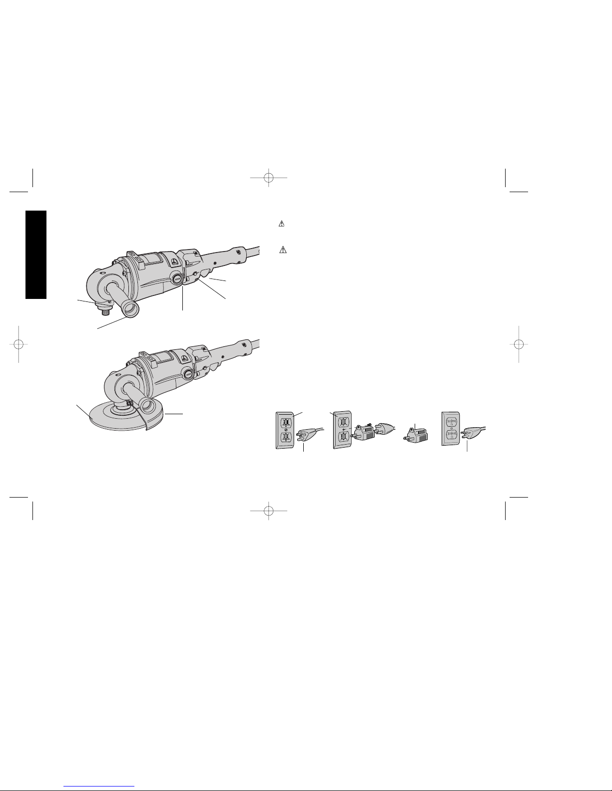
TO CONVERT THE
SANDER TO A
GRINDER, A
GUARD MUST BE
INSTALLED.
SPINDLE
LOCK
BRUSH
INSPECTION
CAP
SWITCH LOCK
BUTTON
TRIGGER
SWITCH
AUXILIARY
HANDLE
GUARD
(NOT SUPPLIED)
DEPRESSED
CENTER WHEEL
AB CD
GROUNDING PIN
GROUNDED
OUTLET
BOX
GROUNDING
MEANS
GROUNDING PIN
ADAPTER
383763-01/DW488 rev. 7/31/2002 1:48 PM Page 4
Page 5
like, extending from the adapter must be connected to a permanent
ground, such as a properly grounded outlet box. No adapter is
available for a plug as shown in sketch D. ADAPTER SHOWN IN
FIGURES B and C IS NOT FOR USE IN CANADA.
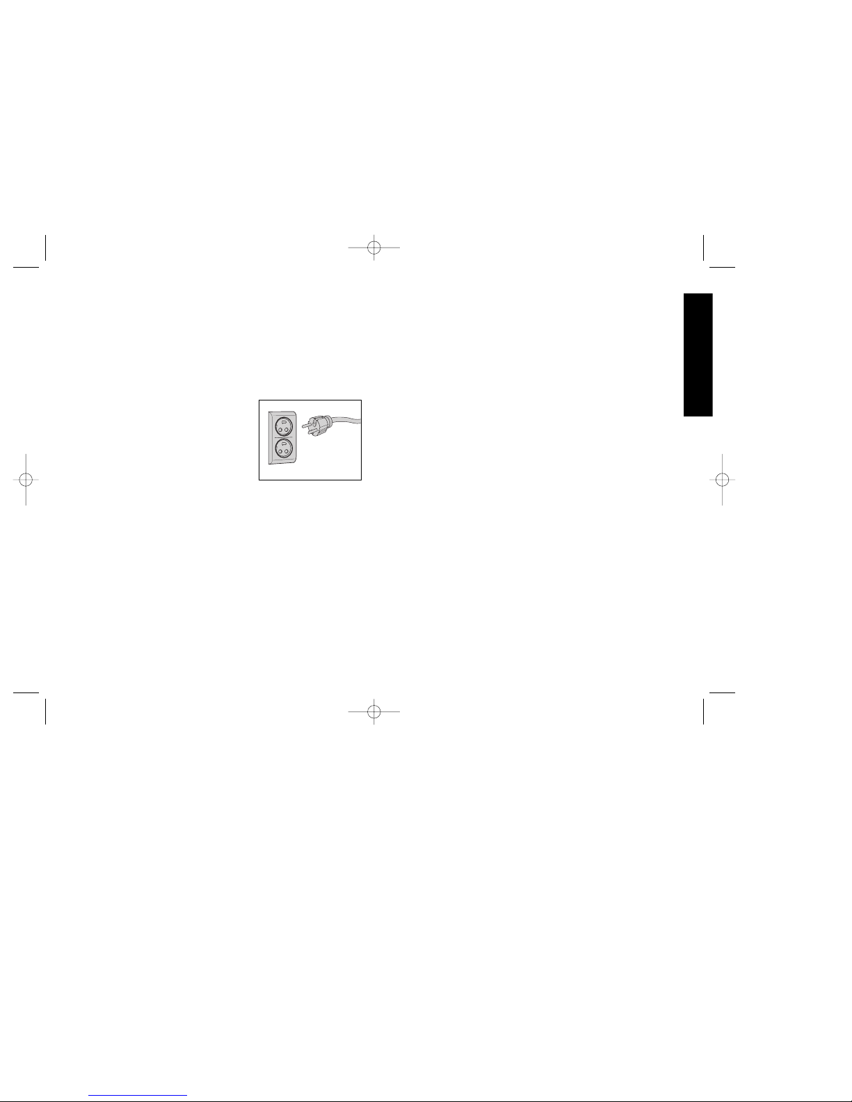
Grounding Instructions
(DW494-220)
This tool should be grounded while in use to protect the operator from
electric shock. The tool is equipped with a 3-conductor cord
to fit the proper grounding type receptacle. The green (or
green and yellow) conductor in the cord is the grounding wire. Never
connect the green (or green and yellow)
wire to a live terminal.
The two grounding contacts and the
grounding receptacle in the plug must be
connected to a permanent ground, such as
a properly grounded outlet. No adapter is
available for a plug as shown in Figure A.
Safety Instructions For
All Tools
• KEEP WORK AREA CLEAN. Cluttered areas and benches invite
injuries.
• CONSIDER WORK AREA ENVIRONMENT. Don’t expose power
tools to rain. Don’t use power tools in damp or wet locations. Keep
work area well lit. Do not use tool in presence of flammable liquids
or gases.
• GUARD AGAINST ELECTRIC SHOCK. Prevent body contact
with grounded surfaces. For example; pipes, radiators, ranges, and
refrigerator enclosures.
• KEEP CHILDREN AWAY. Do not let visitors contact tool or
extension cord. All visitors should be kept away from work area.
• STORE IDLE TOOLS. When not in use, tools should be stored in
dry, and high or locked-up place — out of reach of children.
• DON’T FORCE TOOL. It will do the job better and safer at the
rate for which it was intended.
• USE RIGHT TOOL. Don’t force small tool or attachment to do the
job of a heavy-duty tool. Don’t use tool for purpose not intended.
• DRESS PROPERLY. Do not wear loose clothing or jewelry. They
can be caught in moving parts. Rubber gloves and non-skid
footwear are recommended when working outdoors. Wear
protective hair covering to contain long hair.
Air vents often cover
moving parts and should also be avoided.
• USE SAFETY GLASSES. Also use face or dust mask if operation
is dusty.
• DON’T ABUSE CORD. Never carry tool by cord or yank it to
disconnect from receptacle. Keep cord from heat, oil, and sharp
edges.
• SECURE WORK. Use clamps or a vise to hold work. It’s safer than
using your hand and it frees both hands to operate tool.
• DON’T OVERREACH. Keep proper footing and balance at all
times.
• MAINTAIN TOOLS WITH CARE. Keep tools sharp and clean for
better and safer performance. Follow instructions for lubricating
and changing accessories. Inspect tool cords periodically and if
damaged, have repaired by authorized service facility. Inspect
extension cords periodically and replace if damaged. Keep
handles dry, clean, and free from oil and grease.
• DISCONNECT OR LOCK OFF TOOLS when not in use, before
servicing, and when changing accessories, such as blades, bits,
cutters.
• REMOVE ADJUSTING KEYS AND WRENCHES. Form habit of
checking to see that keys and adjusting wrenches are removed
from tool before turning it on.
• AVOID UNINTENTIONAL STARTING. Don’t carry tool with finger
on switch. Be sure switch is off when plugging in.
• EXTENSION CORDS. Use only 3-wire extension cords that have
1
English
A
383763-01/DW488 rev. 7/31/2002 1:48 PM Page 1
Page 6

2
3-prong grounding-type plugs and 3-pole receptacles that accept
the tool’s plug. Replace or repair damaged cords. Make sure your
extension cord is in good condition. When using an extension cord,
be sure to use one heavy enough to carry the current your product
will draw. An undersized cord will cause a drop in line voltage
resulting in loss of power and overheating. The following table
shows the correct size to use depending on cord length and
nameplate ampere rating. If in doubt, use the next heavier gage.
The smaller the gage number, the heavier the cord.
Recommended Minimum Wire Size for Extension Cords
Total Length of Cord
25 ft. 50 ft. 75 ft. 100 ft. 125 ft. 150 ft. 175 ft.
7.6 m 15.2 m 22.9 m 30.5 m 38.1 m 45.7 m 53.3 m
Wire Size
18 AWG 18 AWG 16 AWG 16 AWG 14 AWG 14 AWG 12 AWG
• OUTDOOR USE EXTENSION CORDS. When tool is used
outdoors, use only extension cords intended for use outdoors and
so marked.
• STAY ALERT. Watch what you are doing. Use common sense.
Do not operate tool when you are tired.
• CHECK DAMAGED PARTS. Before further use of the tool, a
guard or other part that is damaged should be carefully checked
to determine that it will operate properly and perform its intended
function. Check for alignment of moving parts, binding of moving
parts, breakage of parts, mounting, and any other conditions that
may affect its operation. A guard or other part that is damaged
should be properly repaired or replaced by an authorized service
center unless otherwise indicated elsewhere in this instruction
manual. Have defective switches replaced by authorized service
center. Do not use tool if switch does not turn it on and off.
Additional Safety Instructions for
Grinders
• ALWAYS WEAR EYE PROTECTION.
• WHEN GRINDING, ALWAYS KEEP GUARDS IN PLACE.
• Always use proper guard with grinding wheel. A guard protects
operator from broken wheel fragments and wheel contact.
• Always use side handle. Tighten the handle securely. The side
handle should always be used to maintain control of the tool at all
times.
• Accessories must be rated for at least the speed recommended
on the tool warning label. Wheels and other accessories running
over rated speed can fly apart and cause injury. Refer to the table
below. Accessory ratings are above rated no-load tool speeds because
actual tool speeds may vary.
• Use only grinding wheels having a maximum operating speed at
least high as “No Load RPM” marked on the tool’s nameplate.
• Before using, inspect recommended accessory for cracks or flaws.
If such a crack or flaw is evident, discard the accessory. The
accessory should also be inspected whenever you think the tool
may have been dropped.
• When starting the tool (with a new or replacement wheel installed)
hold the tool in a well protected area and let it run for one minute.
If the wheel has an undetected crack or flaw, it should burst in less
than one minute. Never start the tool with a person in line with the
wheel. This includes the operator.
• In operation, avoid bouncing the wheel or giving it rough treatment.
If this occurs, stop the tool and inspect the wheel.
• ALWAYS USE GUARDS with depressed center wheels or flaring
cup grinding wheels.
• Clean your tool out periodically.
CAUTION: Use extra care when grinding into a corner as a sudden,
sharp movement of the grinder may be experienced when the wheel
contacts a secondary surface.
English
383763-01/DW488 rev. 7/31/2002 1:48 PM Page 2
Page 7
CAUTION: Wear appropriate hearing protection during use.
Under some conditions and duration of use, noise from this product
may contribute to hearing loss.
WARNING: Some dust created by power sanding, sawing, grinding,
drilling, and other construction activities contains chemicals known to
cause cancer, birth defects or other reproductive harm. Some
examples of these chemicals are:
• lead from lead-based paints,
• crystalline silica from bricks and cement and other masonry
products, and
• arsenic and chromium from chemically-treated lumber (CCA).
Your risk from these exposures varies, depending on how often you do
this type of work. To reduce your exposure to these chemicals: work in
a well ventilated area, and work with approved safety equipment, such
as those dust masks that are specially designed to filter out
microscopic particles.
• Avoid prolonged contact with dust from power sanding,
sawing, grinding, drilling, and other construction activities.
Wear protective clothing and wash exposed areas with soap
and water. Allowing dust to get into your mouth, eyes, or lay on the
skin may promote absorption of harmful chemicals.
SAVE THESE INSTRUCTIONS
Switch
To start the tool, squeeze the trigger switch shown in Figure 1. To turn
the tool off, release the switch.The tool can be locked on for
continuous use by holding the trigger switch depressed while you
depress the switch locking button next to the trigger, as shown in
Figure1. Hold the locking button in as you gently release the trigger.
Release the locking button and the tool will continue to run. To turn
the tool off from a locked on condition, squeeze and release the
trigger once.
3
English
TRIGGER
SWITCH
SWITCH LOCKING
BUTTON
FIG. 1
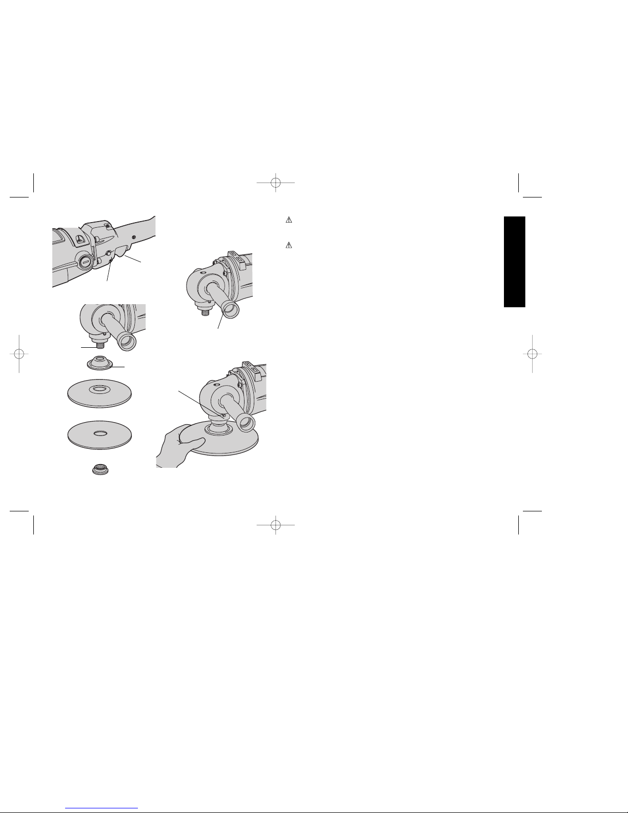
FIG. 2
AUXILIARY HANDLE CAN
BE INSTALLED ON EITHER
SIDE OF THE GEAR CASE
AUXILIARY
HANDLE
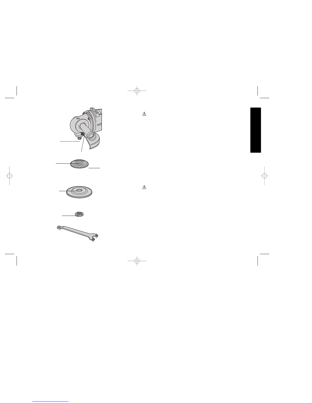
SPINDLE
DISC NUT
HUB
BACKING PAD
ABRASIVE DISC
FIG. 3
FIG. 4
SPINDLE
LOCK
BUTTON
383763-01/DW488 rev. 7/31/2002 1:48 PM Page 3
Page 8
4
Auxiliary Handle
An auxiliary handle is provided with your tool for convenience. The
handle can be screwed into either side of the gear case, as shown in
Figure 2, and should be used at all times when sanding or grinding.
Sanding With Abrasive Discs
Abrasive discs can be used for smoothing welds, removing rust and
paint and general smoothing of rough surfaces.
To install an abrasive disc, follow the steps listed below.
1. TURN OFF TOOL AND DISCONNECT FROM POWER SUPPLY.
2. Push the hub of the disc nut through the hole in the center of the
abrasive disc and the backing disc as far as it will go.
3. Install the assembled discs onto the tool spindle, as shown in
Figure 3, and engage the disc nut into the disc nut hub.
4. Using a glove or cloth to protect your hand, screw the whole
assembly clockwise onto the tool spindle as far as it will go as
shown in Figure 4.
5. Engage the spindle lock button to lock the spindle in place and
tighten firmly. (See Figure 4)
To remove an abrasive disc, follow the steps listed below.
1. Turn off and unplug the tool from the power supply.
2. Using a glove or cloth to protect your hand, turn the assembled
discs counterclockwise as you depress the spindle lock button.
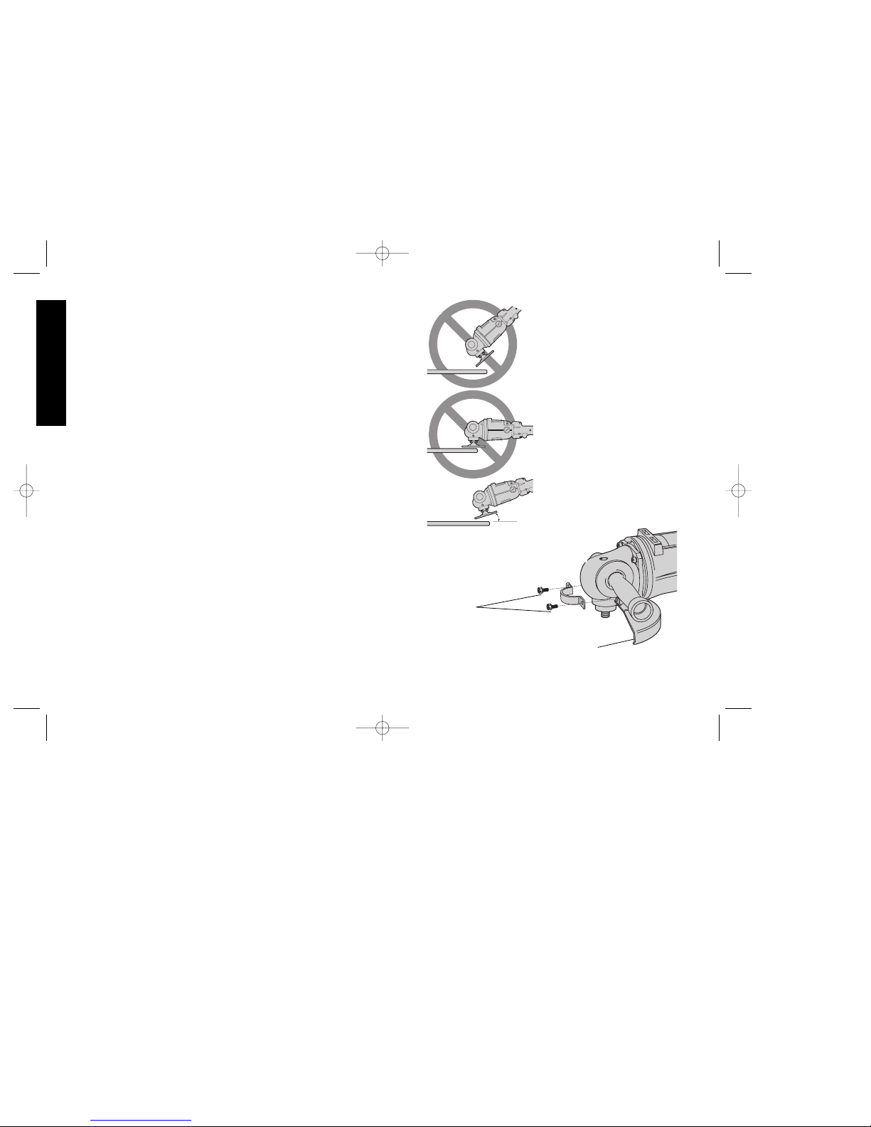
When sanding, maintain an angle of 10-15 degrees between the
abrasive disc and the surface being sanded, as shown in Figure 5.
If only the outer edge of the abrasive disc is used, a rough cut surface
will result. If the disc is pressed flat against the surface, the sanding
action will be bumpy and irregular and the tool will be difficult to
control.
English
FIG. 5
FIG. 6
GUARD
SKIRT
CLAMPING
SCREWS
10 - 15 degrees
383763-01/DW488 rev. 7/31/2002 1:48 PM Page 4
Page 9
Grinding With Depressed Center Wheels
CAUTION: BEFORE ANY GRINDING OPERATIONS, THE
CORRECT GUARD MUST BE MOUNTED TO THE SANDER. THE
MOUNTING OF THIS GUARD CONVERTS YOUR SANDER TO AN
ANGLE GRINDER.
To install the guard to your sander, follow the steps listed
below.
1. If you cannot determine which guard is the correct one, check with
your local D
EWALT service center or call toll free:
1-800-4-DeWALT (1-800-433-9258) .
2. TURN OFF TOOL AND DISCONNECT FROM POWER SUPPLY.
3. Install the guard as shown in Figure 6. Position the guard skirt
between the spindle and the operator.
4. Securely tighten the two clamping screws supplied with the guard.
Depressed center wheels can be used for moderate metal removal on
flat or contoured surfaces.
To install a depressed center wheel, follow the steps listed
below:
CAUTION: NEVER USE DEPRESSED CENTER WHEELS
WITHOUT THE PROPER GUARD.
1. TURN OFF TOOL AND DISCONNECT FROM POWER SUPPLY.
2. Be sure the guard is securely attached to the gear case.
3. Install the backing flange onto the tool spindle, as shown in
Figure 7.
4. Check rated speed of depressed center wheel. Never use wheel
rated at less than speed on the nameplate of the tool.
5. Install the depressed center wheel onto the tool’s spindle, as
shown in Figure 7.
6. Thread the clamp washer onto the tool’s spindle, as shown in
Figure 7. Hold the spindle in place with the locking button and
tighten with the wrench provided.
5
English
SPINDLE LOCK BUTTON
SPINDLE
BACKING FLANGE
DEPRESSED CENTER WHEEL
CLAMP WASHER
FIG. 7
WRENCH
RAISED PORTION OF
WHEEL TOWARD
FLANGE
RAISED PORTION
OF FLANGE
TOWARD SPINDLE
RAISED SHOULDER
TOWARD WHEEL
383763-01/DW488 rev. 7/31/2002 1:48 PM Page 5
Page 10

6
To remove a depressed center wheel follow the steps below:
1. TURN OFF TOOL AND DISCONNECT FROM POWER SUPPLY.
2. Engage the spindle lock by depressing the button shown in
Figure 7 and loosen the clamp washer using the spanner wrench
provided.
3. Examine the depressed center wheel closely for cracks or chips.
If either are found, discard the wheel at once.
When using a depressed center wheel, hold the tool so that an angle
of approximately 30 degrees exists between the wheel and the
surface being ground.
Wire Wheel And Knotted Wire Wheel
Brushes
Wire wheels and brushes can be used for removing rust, scale and
paint, and for smoothing irregular surfaces. A type 27 guard is
required when using wire brushes and wheels.
To install a wire wheel or brush, follow the steps below:
1. TURN OFF TOOL AND DISCONNECT FROM POWER SUPPLY.
2. Rest grinder on its back with the spindle pointing up and remove
guard if desired.
3. Ensure that the rated speed of the wire wheel or brush is equal to
or greater than the rated speed of the grinder found on the tool’s
nameplate.
4. Thread brush or wheel onto spindle and tighten securely.
NOTE: Cover your hand with a glove or cloth when handling wire
wheels and brushes.
Maintenance
CLEANING
Blowing dust and grit out of the motor housing using compressed air
is a necessary regular maintenance procedure. Dust and grit
containing metal particles often accumulate on interior surfaces and
could create an electrical shock hazard if not frequently cleaned out.
ALWAYS WEAR SAFETY GLASSES.
CAUTION: Never use solvents or other harsh chemicals for
cleaning the non-metallic parts of the tool. Use clean, dry cloth only.
LUBRICATION
D
EWALT tools are properly lubricated at the factory and are ready
for use. Tools should be relubricated regularly every sixty days to six
months, depending on usage. (Tools used constantly on production
or heavy-duty jobs and tools exposed to heat may require more
frequent lubrication.) This lubrication should only be attempted by
trained power tool repairpersons, such as those at D
EWALT service
centers or in other qualified service organizations.
Accessories
Recommended accessories for use with your tool are available at
extra cost from your distributor or local service center.
NOTE: USE ACCESSORIES RECOMMENDED PER CHART
BELOW.
Depressed center grinding wheels must fit within the confines of the
guard and must be rated higher than the recommended speed as
marked on the nameplate.
Accessory Type Notes Usage
DEPRESSED CENTER
WHEEL
Use for moderate metal
and masonry removal
on flat or contoured
surfaces
SANDING DISCS
Use for smoothing welds,
and sharp edges, and
automotive body work
WIRE CUP
BRUSHES
Always wear eye protection
and appropriate clothing
Use for rust removal and
surface preparation
before painting
English
383763-01/DW488 rev. 7/31/2002 1:48 PM Page 6
Page 11

Recommended accessories for use with your tool are available at
extra cost from your distributor or local service center. A complete
listing of service centers is included with your tool.
CAUTION: Strands of wire cup brushes may break and fly off
while in use. Users and others in the area should wear adequate eye,
face and body protection. Use only wire cup brushes that are rated at
or greater than the RPM shown on the tool’s nameplate.
WARNING: To reduce the risk of injury, always use proper guards
when grinding and wear eye protection.
CAUTION: The use of any non-recommended accessory may
be hazardous.
Repairs
To assure product SAFETY and RELIABILITY, repairs, maintenance
and adjustment (including brush inspection and replacement) should
be performed by authorized service centers or other qualified service
organizations, always using identical replacement parts.
Full Warranty
DEWALT heavy duty industrial tools are warranted for one year from
date of purchase. We will repair, without charge, any defects due to
faulty materials or workmanship. For warranty repair information,
call 1-800-4-D
EWALT. This warranty does not apply to accessories or
damage caused where repairs have been made or attempted by
others. This warranty gives you specific legal rights and you may
have other rights which vary in certain states or provinces.
In addition to the warranty, D
EWALT tools are covered by our:
30 DAY NO RISK SATISFACTION GUARANTEE
If you are not completely satisfied with the performance of your
D
EWALT heavy duty industrial tool, simply return it to the participating
seller within 30 days for a full refund. Please return the complete unit,
transportation prepaid. Proof of purchase may be required.
FREE WARNING LABEL REPLACEMENT: If your warning labels
become illegible or are missing, call 1-800-4-DEWALT for a free
replacement.
7
English
383763-01/DW488 rev. 7/31/2002 1:48 PM Page 7
Page 12

8
Français
POUR TOUT RENSEIGNEMENT SUPPLÉMENTAIRE SUR CET
OUTIL OU TOUT AUTRE OUTIL D
EWALT, COMPOSER SANS
FRAIS LE NUMÉRO:
1 800 4-DE
WALT (1 800 433-9258)
Importantes mesures de sécurité
AVERTISSEMENT : l’outil peut soulever de la poussière contenant
des produits chimiques pouvant causer le cancer ou des
malformations congénitales ou encore, être nocifs sur le plan
reproductif. On doit donc porter l’appareil de protection respiratoire
approprié.
AVERTISSEMENT : Afin de réduire les risques d’incendie, de
secousses électriques ou de blessures lorsqu’on utilise des outils
électriques, il faut toujours respecter les mesures de sécurité
suivantes.
LIRE TOUTES LES DIRECTIVES.
Mise à la terre (Modèles DW488, DW493,
DW494)
L’outil devrait être mis à la terre lors de son utilisation afin de protéger
l’utilisateur contre les risques de secousses électriques. L’outil est
doté d’un cordon trifilaire et d’une fiche à trois broches de type mis à
la terre qui s’insère dans une prise mise à la terre. Le conducteur vert
(ou vert et jaune) du cordon est le fil de mise à la terre. Ne jamais
raccorder le fil vert (ou vert et jaune) à une borne sous tension.
Lorsque l’outil est conçu pour recevoir une alimentation de moins de
150 volts, il est doté d’une fiche semblable à celle illustrée à la figure
A. Lorsque l’outil est conçu pour recevoir une alimentation variant
AB CD
BROCHE DE PRISE
MISE À LA TERRE
BROCHE DE PRISE
MISE À LA TERRE
PRISE MISE
À LA TERRE
DISPOSITIF DE
MISE À LA TERRE
ADAPTATEUR
POUR TRANSFORMER
LA PONCEUSE EN
RECTIFIEUSE, IL FAUT
INSTALLER UN
PROTECTEUR.S
DISPOSITIF DE
VERROUILLAGE
DE L’ARBRE
COUVERCLE
D’INSPECTION
DES BALAIS
BOUTON DE
VERROUILLAGE DE
L’INTERRUPTEUR
INTERRUPTEUR
À DÉTENTE
POIGNÉE
AUXILIAIRE
PROTECTEUR
(NON COMPRIS)
MEULE À
MOYEU CREUX
383763-01/DW488 rev. 7/31/2002 1:48 PM Page 8
Page 13

entre 150 et 250 volts, il est doté d’une fiche semblable à celle
illustrée à la figure D. On peut se procurer un adaptateur (fig. B et C)
pour brancher une fiche semblable à celle de la figure A dans des
prises à deux orifices. Il faut alors relier la tige, la cosse ou le
dispositif similaire de couleur verte à une mise à la terre permanente
(comme une prise bien mise à la terre). Il n’y a pas d’adaptateur pour
la fiche illustrée à la figure D. L’ADAPTATEUR ILLUSTRÉ AUX
FIGURES B ET C NE PEUT PAS ETRE UTILISÉ AU CANADA.
Utiliser seulement des cordons de rallonge trifilaires qui acceptent
des fiches à 3 broches et des prises à 3 orifices qui acceptent la fiche
de l’outil. Remplacer ou réparer les cordons endommagés.
Mise à la terre (Modèle DW494-220)
L’outil devrait être mis à la terre lorsqu’on
s’en sert afin de protéger l’utilisateur contre
les risques de secousses électriques.
L’outil comporte un cordon trifilaire
convenant à une prise bien mise à la terre.
Le conducteur vert (ou vert et jaune)
constitue le fil de terre. Ne jamais relier le fil
vert (ou vert et jaune) à une borne sous
tension.
Il faut relier les deux contacts de terre et la prise de terre de la fiche
à une mise à la terre permanente, comme une prise bien mise à la
terre. Il n’existe aucun adaptateur pour la fiche illustrée à la figure A.
Mesures de sécurité pour tous les outils
• BIEN DÉGAGER LA SURFACE DE TRAVAIL. Des surfaces et
des établis encombrés peuvent être la cause de blessures.
• TENIR COMPTE DU MILIEU DE TRAVAIL. Protéger les outils
électriques de la pluie. Ne pas s’en servir dans des endroits
humides ou mouillés. Bien éclairer la surface de travail. Ne pas se
servir de l’outil en présence de liquides ou de vapeurs
inflammables.
• SE PROTÉGER CONTRE LES SECOUSSES ÉLECTRIQUES.
Éviter tout contact avec des objets mis à la terre, comme des
tuyaux, radiateurs, cuisinières, réfrigérateurs et autres objets du
genre.
• ÉLOIGNER LES ENFANTS. Tous les visiteurs doivent être tenus
à l’écart de l’aire de travail et il faut les empêcher de toucher à
l’outil ou au cordon de rallonge.
• RANGER LES OUTILS INUTILISÉS. Il faut ranger les outils dans
un endroit sec, situé en hauteur ou fermé à clé, hors de la portée
des enfants.
• NE JAMAIS FORCER L’OUTIL. Afin d’obtenir un rendement sûr
et efficace, utiliser l’outil à son rendement nominal.
• UTILISER L’OUTIL APPROPRIÉ. Ne jamais exiger d’un petit outil
ou d’un accessoire le rendement d’un outil de fabrication plus
robuste. Se servir de l’outil selon l’usage prévu.
• PORTER DES VÊTEMENTS APPROPRI´ES. ´Eviter de porter de
vêtements amples et des bijoux qui peuvent être happés par les pièces
en mouvement. Porter des gants de caoutchouc et des chaussures à
semelle antidérapante pour travailler à l’exteriur. Protéger la chevelure
si elle est longue. Se tenir éloigné des évents puisque ces derniers
pourraient camoufler des pièces mobiles.
• PORTER DES LUNETTES DE SÉCURITÉ. Porter également un
masque respiratoire si le travail de coupe produit de la poussière.
• NE PAS MANIPULER LE CORDON DE FAÇON ABUSIVE. Ne
pas transporter l’outil par le cordon ni tirer sur ce dernier pour le
débrancher de la prise. Éloigner le cordon des sources de chaleur,
des flaques d’huile et des arêtes tranchantes.
• ASSUJETTIR LA PIÈCE. Immobiliser la pièce à l’aide de brides
ou d’un étau. On peut alors se servir des deux mains pour faire
fonctionner l’outil, ce qui est plus sûr.
• NE PAS DÉPASSER SA PORTÉE. Toujours demeurer dans une
position stable et garder son équilibre.
• PRENDRE SOIN DES OUTILS. Conserver les outils propres pour
qu’ils donnent un rendement supérieur et sûr. Suivre les directives
9
Français
A
383763-01/DW488 rev. 7/31/2002 1:48 PM Page 9
Page 14

10
concernant la lubrification et le remplacement des accessoires.
Inspecter régulièrement le cordon de l’outil et le faire réparer au
besoin à un atelier d’entretien autorisé. Inspecter régulièrement les
cordons de rallonge et les remplacer lorsqu’ils sont endommagés.
S’assurer que les poignées sont toujours propres, sèches et libres
de toute tache d’huile ou de graisse.
• DÉBRANCHER OU VERROUILLER EN POSITION HORS
TENSION LES OUTILS NON UTILISÉS. Respecter cette mesure
lorsqu’on ne se sert pas de l’outil, ou qu’on doit le réparer ou en
changer un accessoire (comme une lame, un foret ou un couteau).
• ENLEVER LES CLÉS DE RÉGLAGE. Prendre l’habitude de
vérifier si les clés de réglage ont été retirées avant de faire
démarrer l’outil.
• ÉVITER LES DÉMARRAGES ACCIDENTELS. Ne pas laisser le
doigt sur l’interrupteur lorsqu’on transporte l’outil. S’assurer que
l’interrupteur est à la position hors circuit lorsqu’on branche l’outil.
• CORDONS DE RALLONGE. S’assurer que le cordon de rallonge
est en bon état. Lorsqu’on se sert d’un cordon de rallonge,
s’assurer qu’il est de calibre approprié pour la tension nécessaire
au fonctionnement de l’outil. L’utilisation d’un cordon de calibre
inférieur occasionne une baisse de tension entraînant une perte de
puissance et la surchauffe. Le tableau suivant indique le calibre
approprié selon la longueur du cordon et les mentions de la plaque
signalétique de l’outil. En cas de doute, utiliser un cordon de calibre
supérieur. Le chiffre indiquant le calibre est inversement
proportionnel au calibre du cordon.
Calibre minimal des cordons de rallonge
Longueur totale du cordon
25 ft. 50 ft. 75 ft. 100 ft. 125 ft. 150 ft. 175 ft.
7.6 m 15.2 m 22.9 m 30.5 m 38.1 m 45.7 m 53.3 m
Intensité
18 AWG 18 AWG 16 AWG 16 AWG 14 AWG 14 AWG 12 AWG
• CORDONS DE RALLONGE PRÉVUS POUR L’EXTÉRIEUR.
Lorsque l’outil est utilisé à l’extérieur, ne se servir que d’un cordon
de rallonge conçu pour l’extérieur et portant la mention appropriée.
• DEMEURER VIGILANT. Travailler avec vigilance et faire preuve
de bon sens. Ne pas se servir de l’outil lorsqu’on est fatigué.
• VÉRIFIER LES PIÈCES ENDOMMAGÉES. Avant de continuer à
utiliser l’outil, il faut vérifier si le protecteur ou toute autre pièce
endommagée remplit bien la fonction pour laquelle il a été prévu.
Vérifier l’alignement et les attaches des pièces mobiles, le degré
d’usure des pièces et leur montage, ainsi que tout autre facteur
susceptible de nuire au bon fonctionnement de l’outil. Faire réparer
ou remplacer tout protecteur ou toute autre pièce endommagée
dans un centre de service autorisé, sauf si le présent guide fait
mention d’un avis contraire. Confier le remplacement de tout
interrupteur défectueux à un centre de service autorisé. Ne jamais
se servir d’un outil dont l’interrupteur est défectueux.
Mesures de sécurité additionnelles
relatives aux rectifieuses
• TOUJOURS PORTER DES LUNETTES DE SÉCURITÉ.
• S’ASSURER QUE LES PROTECTEURS SONT EN PLACE.
• Toujours utiliser le dispositif de protection qui convient à la
meule afin d’éviter tout contact avec celle-ci et de protéger
l’opérateur des fragments pouvant être projetés par une meule
brisée.
• Toujours utiliser la poignée latérale et s’assurer qu’elle est bien
serrée afin de bien maîtriser l’outil en tout temps.
• La vitesse des accessoires doit correspondre à la vitesse
minimale recommandée indiquée sur l’étiquette d’avertissement
de l’outil, car les meules et les accessoires qui sont réglés à une
vitesse trop élevée peuvent se briser et occasionner des blessures
lorsque des fragments de métal sont projetés. La vitesse des
accessoires est réglée au-dessus de la vitesse à vide de l’outil puisque
la vitesse réelle de l’outil peut varier.
• Avant de s’en servir, vérifier si les accessoires recommandés ne
Français
383763-01/DW488 rev. 7/31/2002 1:48 PM Page 10
Page 15

renferment aucune fêlure ni défaut. Le cas échéant, jeter
l’accessoire. Il faut également inspecter l’accessoire lorsque l’outil
est tombé.
• Au moment du démarrage (après avoir installé une nouvelle
meule), saisir l’outil dans un endroit bien protégé et le laisser
fonctionner pendant une minute. Si la meule renferme une fêlure
ou un défaut non décelé, elle éclatera en moins de une minute.
Ne jamais mettre l’outil en marche lorsqu’une personne se trouve
dans la trajectoire de la meule. Cette mesure vaut également pour
l’utilisateur.
• Pendant les travaux, éviter de faire sauter la meule ou de la
maltraiter. Le cas échéant, arrêter l’outil et inspecter la meule.
• TOUJOURS UTILISER DES PROTECTEURS avec des meules
à moyeu creux ou des meules boisseau coniques.
• Nettoyer l’outil régulièrement.
MISE EN GARDE : porter un dispositif de protection personnel
anti-bruit approprié durant l’utilisation. Sous certaines conditions et
pendant toute la durée de l’utilisation, le bruit émanant de ce produit
pourrait contribuer à la perte d’audition.
MISE EN GARDE : faire preuve d’une grande prudence lorsqu’on
meule dans un coin, car la meuleuse pourrait rebondir soudainement
si la meule entre en contact avec une autre surface.
AVERTISSEMENT : Certains outils, tels que les sableuses
électriques, les scies, les meules, les perceuses ou certains autres
outils de construction, peuvent soulever de la poussière contenant des
produits chimiques susceptibles d’entraîner le cancer, des
malformations congénitales ou pouvant être nocifs pour le système
reproductif. Parmi ces produits chimiques, on retrouve :
• le plomb dans les peintures à base de plomb;
• la silice cristalline dans les briques et le ciment et autres produits de
maçonnerie;
• l’arsenic et le chrome dans le bois de sciage ayant subi un
traitement chimique (CCA).
11
Français
INTERRUPTEUR À
DÉTENTE
BOUTON DE
VERROUILLAGE DE
L’INTERRUPTEUR
FIG. 1
FIG. 2
LA POIGNÉE AUXILIAIRE
S’INSTALLE D’UN COTÉ OU
DE L’AUTRE DU BOITIER
DES ENGRENAGES.
POIGNÉE
AUXILIAIRE
ARBRE
MOYEU DE
L’ÉCROU DU
DISQUE
TAMPON D’APPUI
DISQUE ABRASIF
FIG. 3
383763-01/DW488 rev. 7/31/2002 1:48 PM Page 11
Page 16

12
Le risque associé à de telles expositions peut varier selon la fréquence
avec laquelle on effectue ces travaux. Pour réduire l’exposition à de
tels produits, il faut travailler dans un endroit bien ventilé et utiliser
l’équipement de sécurité approprié tel un masque anti-poussières
spécialement conçu pour filtrer les particules microscopiques.
• Éviter tout contact prolongé avec la poussière soulevée par
cet outil ou autres outils électriques. Porter des vêtements
de protection et nettoyer les parties exposées du corps avec
de l’eau savonneuse. S’assurer de bien se protéger afin d’éviter
d’absorber par la bouche, les yeux ou la peau des produits
chimiques nocifs.
CONSERVER CES MESURES.
Interrupteur
Enfoncer l’interrupteur à détente (fig. 1) pour actionner l’outil. Pour
l’arrêter, relâcher l’interrupteur. On peut verrouiller l’outil en mode de
fonctionnement continu en maintenant l’interrupteur à détente
enfoncé tout en enfonçant le bouton de verrouillage de l’interrupteur
qui se trouve près de la détente (fig. 1). Maintenir le bouton de
verrouillage enfoncé et relâcher doucement la détente. Relâcher le
bouton de verrouillage et l’outil continue de fonctionner. Pour l’arrêter
lorsqu’il est en mode de fonctionnement continu, il suffit d’enfoncer et
de relâcher l’interrupteur à détente.
Poignée auxiliaire
À titre de commodité, l’outil comporte une poignée auxiliaire. On peut
l’installer d’un côté ou de l’autre du boîtier des engrenages (fig. 2) et
il faut s’en servir en tout temps lors des travaux de ponçage et de
meulage.
Ponçage à l’aide de disques abrasifs
On utilise des disques abrasifs pour poncer les soudures, enlever
de la rouille et de la peinture et poncer des surfaces rugueuses.
Français
FIG. 4
BOUTON DE
VERROUILLAGE
DE L’ARBRE
FIG. 5
FIG. 6
COLLERETTE DU
PROTECTEUR
VIS DE
SERRAGE
DE 10 À 15 DEGRÉS
383763-01/DW488 rev. 7/31/2002 1:48 PM Page 12
Page 17

Faire ce qui suit pour installer un disque abrasif.
1. METTRE L’OUTIL HORS TENSION ET LE DÉBRANCHER.
2. Pousser le moyeu de l’écrou du disque le plus loin possible au
centre du disque abrasif, puis sur le disque d’appui.
3. Installer les disques assemblés sur l’arbre de l’outil (fig. 3) et
placer l’écrou sur le moyeu.
4. Se protéger la main avec un gant ou un chiffon et visser
l’assemblage dans le sens horaire jusqu’au bout de l’arbre (fig. 4).
5. Actionner le bouton pour verrouiller l’arbre en place et bien le
serrer (fig. 4).
Faire ce qui suit pour retirer un disque abrasif.
1. METTRE L’OUTIL HORS TENSION ET LE DÉBRANCHER.
2. Se protéger la main avec un gant ou un chiffon et visser
l’assemblage dans le sens antihoraire tout en enfonçant le bouton
de verrouillage de l’arbre.
Lorsqu’on ponce, tenir l’outil de sorte qu’il y ait un angle de 10°à15°
entre le disque et la surface à poncer, comme le montre la figure 5.
Si on n’utilise que l’extrémité extérieure du disque, la surface est
poncée grossièrement. Lorsque le disque est à plat contre la pièce,
le ponçage obtenu est irrégulier et raboteux, et l’outil est difficile à
maîtriser.
Meulage à l’aide de meules à moyeu
creux
MISE EN GARDE : NE JAMAIS MEULER SANS AVOIR
INSTALLÉ AU PRÉALABLE LES PROTECTEURS APPROPRIÉS.
L’INSTALLATION DU PRÉSENT PROTECTEUR TRANSFORME LA
PONCEUSE EN RECTIFIEUSE COUDÉE.
Faire ce qui suit pour installer le protecteur.
1. Lorsqu’on n’arrive pas à déterminer le protecteur approprié,
vérifier auprès du personnel du centre de service DEWALT de la
13
Français
BOUTON DE VERROUILLAGE
DE L’ARBRE
ARBRE
BRIDE D’APPUI
MEULE À MOYEU CREUX
RONDELLE DE BLOCAGE
FIG. 7
CLÉ
PORTION ÉLEVÉE DE
LA MEULE VERS LA
BRIDE
PORTION ÉLEVÉE
DE LA BRIDE VERS
L’ARBRE
ÉPAULEMENT
VERS LA MEULE
383763-01/DW488 rev. 7/31/2002 1:48 PM Page 13
Page 18

14
région ou composer le numéro sans frais suivant.
1 (800) 4-DeWALT (1 (800) 433-9258) .
2. METTRE L’OUTIL HORS TENSION ET LE DÉBRANCHER.
3. Installer le protecteur de la façon illustrée à la figure 6. Placer la
collerette du protecteur entre l’arbre et l’utilisateur.
4. Bien serrer les deux vis de serrage fournies avec le protecteur.
Les meules à moyeu creux peuvent servir pour meuler des quantités
modérées de métal sur des surfaces planes ou sculptées.
Faire ce qui suit pour installer une meule à moyeu creux.
MISE EN GARDE : Ne jamais utiliser les meules à moyeu creux
sans les protecteurs appropriés.
1. METTRE L’OUTIL HORS TENSION ET LE DÉBRANCHER.
2. Vérifier si le protecteur est bien fixé au boîtier des engrenages.
3. Installer la bride d’appui sur l’arbre de la façon illustrée à la
figure 7.
4. Vérifier la vitesse nominale indiquée sur la meule à moyeu creux.
Ne jamais utiliser une meule dont la vitesse nominale est
inférieure à celle indiquée sur la plaque signalétique de l’outil.
5. Installer la meule à moyeu creux sur l’arbre de la façon illustrée à
la figure 7.
6. Visser la rondelle de blocage sur l’arbre de la façon illustrée à la
figure 7. Retenir l’arbre en actionnant le bouton de verrouillage et
serrer la rondelle de blocage avec la clé fournie.
Faire ce qui suit pour retirer une meule à moyeu creux.
1. METTRE L’OUTIL HORS TENSION ET LE DÉBRANCHER.
2. Bloquer l’arbre à l’aide du bouton de verrouillage (fig. 7) et
desserrer la rondelle de blocage à l’aide de la clé à fourches
fournie.
3. Vérifier attentivement la meule à moyeu creux afin d’en déceler
toute fêlure ou craque. Le cas échéant, jeter immédiatement la
meule.
Lorsqu’on utilise une meule à moyeu creux, tenir l’outil de sorte qu’il
y ait un angle d’environ 30° entre la meule et la pièce.
Meules boisseaux métalliques et
brosses métalliques torsadées
On utilise une meule boisseau métallique et une brosse métallique
torsadée pour enlever de la rouille, du tartre et de la peinture ainsi
que poncer des surfaces rugueuses. Il faut installer un dispositif de
protection n° 27 lors de l’utilisation des brosses et des meules
métalliques.
Faire ce qui suit pour installer une meule boisseau métallique
ou une brosse métallique.
1. METTRE L’OUTIL HORS TENSION ET LE DÉBRANCHER.
2. Déposer la rectifieuse en la plaçant de sorte que l’arbre soit placé
vers le haut et retirer le protecteur au besoin.
3. S’assurer que la vitesse nominale de la meule boisseau
métallique ou de la brosse métallique est égale ou supérieure
à celle indiquée sur la plaque signalétique de l’outil.
4. Visser la meule boisseau métallique ou la brosse métallique sur
l’arbre et serrer fermement.
MISE EN GARDE : on doit porter des gants de travail lorsqu’on
manipule les brosses métalliques en forme de coupelle.
Entretien
NETTOYAGE
Il faut nettoyer régulièrement le carter du moteur à l’air comprimé afin
d’en chasser la poussière et les résidus. En effet, la poussière et les
résidus de métaux s’accumulent souvent sur les surfaces intérieures
de l’outil et cela présente un risque de secousses électriques si le
carter n’est pas nettoyé fréquemment. TOUJOURS PORTER DES
LUNETTES DE SÉCURITÉ.
Français
383763-01/DW488 rev. 7/31/2002 1:48 PM Page 14
Page 19

MISE EN GARDE : Ne jamais utiliser de solvants ni tout autre
produit chimique pour nettoyer les pièces non métalliques de l’outil.
Utiliser seulement un chiffon propre et sec.
LUBRIFICATION
L’outil DEWALT a été lubrifié en usine et il est prêt à servir. Il faut le
lubrifier au bout de soixante jours à six mois, selon l’utilisation qui en
a été faite. (Les outils constamment utilisés et ceux exposés à la
chaleur peuvent nécessiter une lubrification plus fréquente.) Il faut
confier la lubrification à du personnel qualifié comme celui d’un
centre de service D
EWALT ou d’un atelier d’entretien autorisé.
Accessoires
Les accessoires recommandés pour l’outil sont vendus séparément
chez le distributeur ou au centre de service de la région.
NOTE : UTILISER DES ACCESSOIRES RECOMMANDÉS
CONFORMÉMENT AU TABLEAU SUIVANT.
Type d’accessoire
MEULE À MOYEU
CREUX
DISQUES ABRASIFS
MEULES BOISSEAUX
MÉTALLIQUES
Notes
Toujours porter des
lunettes de sécurité et
des vêtements
appropriés.
Usage
Pour meuler des
quantités modérées de
métal ou de maçonnerie
sur des surfaces planes
ou sculptées.
Pour poncer des
soudures, des arêtes
tranchantes et de la
carrosserie.
Pour enlever de la
rouille et préparer des
surfaces à peindre.
Les meules à moyeu creux doivent s’adapter dans les limites du
protecteur et leur vitesse nominale doit être supérieure à celle
indiquée sur la plaque signalétique de l’outil.
Les accessoires recommandés pour l’outil sont vendus séparément
chez le distributeur ou au centre de service de la région. La liste
complète des centres de service se trouve dans l’emballage de l’outil.
MISE EN GARDE : Les meules boisseaux métalliques peuvent
perdre des fils pendant les travaux et ces derniers son alors éjectés.
L’utilisateur et toute autre personne dans la zone de travail doivent
donc porter des lunettes de sécurité ainsi que de l’équipement
protecteur pour le corps et le visage. Utiliser seulement des meules
boisseaux métalliques dont la vitesse nominale est égale ou
supérieure à celle indiquée sur la plaque signalétique de l’outil.
AVERTISSEMENT : Afin de minimiser les risques de blessures,
toujours utiliser les protecteurs appropriés et porter des lunettes de
sécurité.
MISE EN GARDE : L’utilisation de tout accessoire non
recommandé peut être dangereuse.
Reparations
Pour assurer la SÉCURITÉ D’EMPLOI et la FIABILITÉ de l’outil, n’en
confier la réparation, l’entretien et les rajustements (y compris
l’inspection des balais) qu’à un centre de service ou à un atelier
d’entretien autorisé n’utilisant que des pièces de rechange
identiques.
REMPLACEMENT GRATUIT DE L'ÉTIQUETTE
Si vos étiquettes d'avertissement deviennent illisibles ou sont
manquantes, composez le 1-800-4-D
EWALT pour obtenir une étiquette
de remplacement gratuite.
15
Français
383763-01/DW488 rev. 7/31/2002 1:48 PM Page 15
Page 20

16
Instrucciones importantes de seguridad
ADVERTENCIA: El uso de esta herramienta puede generar
polvo con contenido de productos químicos que se sabe que causan
cáncer, defectos congénitos u otros daños reproductivos. Utilice la
protección respiratoria adecuada.
ADVERTENCIA: Es indispensable sujetarse a las precauciones
básicas de seguridad, con la finalidad de reducir el peligro de
incendio, choque eléctrico y lesiones personales, en todas las
ocasiones en que se utilicen herramientas eléctricas. Entre estas
precauciones se incluyen la siguientes:
LEA TODAS LAS INSTRUCCIONES
Instrucciones de aterrizaje (DW488,
DW493, DW494)
Esta herramienta debe conectarse a tierra para proteger al operador
de choques eléctricos. Esta unidad está equipada con un cordón
eléctrico de tres hilos aprobado y una clavija para aterrizaje de tres
patas para conectarse a la toma de corriente adecuada. El conductor
verde (o verde y amarillo) es el cable de tierra. Nunca conecte el
cable verde (o verde y amarillo) a una terminal viva. Si su unidad
está hecha para funcionar con menos de 150 volts, tiene una clavija
similar a la que se muestra en la figura A. Si es para usarse con
corriente de 150 a 250 volts, tiene una clavija como la que se
muestra en la figura D. Hay
Español
PARA CONVERTIR
LA LIJADORA EN
ESMERILADORA
DEBE INSTALARSE
UNA GUARDA
SEGURO
DE LA
FLECHA
TAPA DE
INSPECCION
DE CARBONES
BOTON DE
SEGURO DEL
INTERRUPTOR
GATILLO
INTERRUPTOR
MANGO
AUXILIAR
GUARDA (NO
SUMINISTRADA)
DISCO DE
CENTRO
HENDIDO
AB CD
PATA DE
CONEXION A
TIERRA
PATA DE
CONEXION A
TIERRA
TOMA DE
CORRIENTE
ATERRIZADA
MEDIO DE
ATERRIZAJE
ADAPTADOR
383763-01/DW488 rev. 7/31/2002 1:48 PM Page 16
Page 21

adaptadores, figuras B y C, para conectar clavijas del tipo de la figura
A a tomas de corriente para dos patas. La oreja de color verde
deberá conectarse a tierra permanente, tal como una toma de
corriente aterrizada adecuadamente. No hay adaptadores para
clavijas como la de la figura D. EL ADAPTADOR MOSTRADO EN
LAS FIGURAS B Y C NO ESTA HECHO PARA USARSE EN
CANADA.
Instrucciones de conexión a tierra
(DW949-220)
Esta herramienta debe conectarse a tierra
durante su operación para proteger al
operador de un posible choque eléctrico.
La herramienta está equipada con un
cable con 3 conductores para acoplarse a
la toma de corriente aterrizada apropiada.
El conductor verde (o verde con amarillo)
del cable es el de conexión a tierra. Nunca
conecte el cable verde (o verde con
amarillo) a una terminal viva.
Los dos contactos de conexión a tierra y la toma de aterrizaje en la
clavija deben conectarse a tierra permanente, tal como un contacto
aterrizado. No existen adaptadores para las clavijas como la que se
muestra en la figura A.
Instrucciones de seguridad para todas
las herramientas
• CONSERVE LIMPIA LA ZONA DE TRABAJO. Las superficies y
los bancos con objetos acumulados en desorden propician los
accidentes.
• OTORGUE PRIORIDAD A LA ZONA DE TRABAJO. No deje las
herramientas eléctricas expuestas a la lluvia. No las utilice en
lugares inundados o mojados. Conserve bien iluminada la zona de
trabajo. No utilice la herramienta en presencia de líquidos o gases
inflamables.
• PROTEJASE CONTRA EL CHOQUE ELECTRICO. Evite el
contacto corporal con superficies aterrizadas, por ejemplo,
tuberías, radiadores, antenas y gabinetes de refrigeración.
• CONSERVE APARTADOS A LOS NIÑOS. No permita que los
visitantes toquen las herramientas o los cables de extensión. Todos
los visitantes deben estar alejados de la zona de trabajo.
• GUARDE LAS HERRAMIENTAS QUE NO EMPLEE. Las
herramientas que no se utilizan deben guardarse en un lugar seco
y elevado o bajo llave — fuera del alcance de los niños.
• NO FUERCE LA HERRAMIENTA. Esta cumplirá su función mejor
y con más seguridad a la velocidad y la presión para las que se
diseñó.
• VISTASE ADECUADAMENTE. No utilice ropa floja o joyas. Cubra su
cabello. Conserve su cabello, ropas y guantes alejados de las piezas
móviles. Las piezas de vestir flojas, las joyas y el cabello largo pueden
resultar atrapados por las piezas móviles. Las rejillas de ventilación
cubren partes móviles y también deben evitarse.
• VISTASE DE LA MANERA ADECUADA. No use ropas o artículos
de joyería flojos, pues podrían quedar atrapados por las partes
móviles de las herramientas. Se recomienda el empleo de guantes
de caucho y calzado antiderrapante cuando se trabaje al aire libre.
Cúbrase bien la cabeza para sujetarse el cabello si lo tiene largo.
Las rejillas de ventilación cubren partes móviles y también deben
evitarse.
• COLOQUESE ANTEOJOS DE SEGURIDAD. Póngase también
una mascarilla contra el polvo si lo produce la operación que va a
efectuar.
• TENGA CUIDADO CON EL CORDON ELECTRICO. Nunca
levante la herramienta tomándola por el cordón, ni tire de éste para
desconectarlo del enchufe. Apártelo del calor y los objetos
calientes, las substancias grasosas y los bordes cortantes.
• ASEGURE LOS OBJETOS SOBRE LOS QUE TRABAJE. Utilice
prensas o tornillos de banco para sujetar los objetos sobre los que
va a trabajar. Esto ofrece mayor seguridad que sujetar los objetos
con la mano, y además deja libres ambas manos para operar la
herramienta.
17
Español
A
383763-01/DW488 rev. 7/31/2002 1:48 PM Page 17
Page 22

18
• CONSERVE EL EQUILIBRIO. Conserve en todo momento bien
apoyados los pies, lo mismo que el equilibrio.
• CUIDE SUS HERRAMIENTAS. Conserve sus herramientas
afiladas y limpias para que funcionen mejor y con mayor seguridad.
Siga las instrucciones para lubricación y cambio de accesorios de
su unidad. Revise periódicamente el cordón eléctrico y hágalo
reparar o reemplazar por un centro de servicio si está dañado.
Cambie los cordones de extensión si están dañados. Conserve las
empuñaduras secas, limpias y libres de aceite y grasa.
• DESCONECTE Y APAGUE LAS HERRAMIENTAS cuando no las
use, antes de darles servicio y cuando cambie accesorios, tales
como discos, brocas y otros dispositivos de corte.
• RETIRE LAS LLAVES DE AJUSTE Y DE TUERCAS. Adquiera el
hábito de asegurarse que se han retirado las llaves de ajuste de las
herramientas antes de accionarlas.
• EVITE QUE LA HERRAMIENTA SE ACCIONE
ACCIDENTALMENTE. Nunca sostenga una herramienta que está
conectada con el dedo en el interruptor. Asegúrese que el
interruptor está en posición de “apagado” antes de conectar la
unidad.
• CORDONES DE EXTENSION. Asegúrese que su cordón de
extensión esté en buenas condiciones. Cuando utilice un cordón
de extensión, asegúrese que tenga el calibre suficiente para
soportar la corriente necesaria para su herramienta. Un cordón
eléctrico con calibre insuficiente causará una caída en el voltaje de
la línea, resultando en pérdida de potencia y sobrecalentamiento.
La tabla siguiente ilustra el calibre correcto que debe utilizarse de
conformidad con la longitud del cordón y el amperaje descrito por la
placa de identificación. Si tiene alguna duda, utilice el cable con el
calibre siguiente (mayor). Mientras más chico sea el número,
mayor será su calibre.
Calibre mínimo requerido (AWG) para cables de extensión
Longitud total del cable de extensión
25 ft. 50 ft. 75 ft. 100 ft. 125 ft. 150 ft. 175 ft.
7.6 m 15.2 m 22.9 m 30.5 m 38.1 m 45.7 m 53.3 m
Calibre promedio del alambre
18 AWG 18 AWG 16 AWG 16 AWG 14 AWG 14 AWG 12 AWG
• CORDONES DE EXTENSION PARA INTEMPERIE. Cuando
opere su herramienta a la intemperie, utilice únicamente cordones
de extensión diseñados y marcados para este fin.
• NO SE DISTRAIGA. Concéntrese en lo que está haciendo.
Recurra al sentido común. No opere ninguna herramienta si está
fatigado.
• VERIFIQUE LAS PARTES DAÑADAS. Antes de seguir
empleando cualquier herramienta, es indispensable verificar con
mucho cuidado que las guardas u otras partes dañadas puedan
operar de la manera adecuada para cumplir con su función.
Verifique la alineación de las partes móviles, la firmeza con que
deben encontrarse sujetas a sus montaduras, las partes rotas, las
propias montaduras y cualesquiera otros detalles que pudieran
afectar la operación de la herramienta. Las guardas y otras partes
que se encuentren dañadas deberán cambiarse o repararse en un
centro de servicio autorizado, a menos que se diga otra cosa en
el manual del usuario. Haga que se cambien los interruptores
dañados en un centro de servicio autorizado. No emplee ninguna
herramienta que tenga estropeado o inutilizado el interruptor.
Instrucciones de seguridad adicionales
para esmeriladores
• SIEMPRE UTILICE PROTECCION PARA LOS OJOS.
• CONSERVE LAS GUARDAS EN SU LUGAR.
Español
383763-01/DW488 rev. 7/31/2002 1:48 PM Page 18
Page 23

minuto. Nunca encienda la herramienta con una persona alineada
con la rueda. Esto incluye al operador.
• Durante la operación, evite hacer que la rueda rebote así como
darle tratamiento rudo. Si esto ocurre, apague la herramienta y
revise la rueda.
• SIEMPRE UTILICE GUARDAS con las ruedas de centro hundido,
o con piedras de copa.
• Limpie su herramienta periódicamente.
PRECAUCION: utilice la protección auditiva apropiada durante el
uso. Bajo ciertas condiciones de duración de uso, el ruido producido
por este producto puede contribuir a la pérdida auditiva.
ADVERTENCIA : Parte del polvo creado al lijar, aserruchar, moler
o perforar con máquina, así como al realizar otras actividades de la
construcción, contiene substancias químicas que se sabe producen
cáncer, defectos congénitos u otras afecciones reproductivas. Algunos
ejemplos de esas substancias químicas son:
• plomo de pinturas a base de plomo,
• sílice cristalizado de ladrillos y cemento y otros productos de
albañilería, y
• arsénico y cromo de la madera químicamente tratada (CCA).
El riesgo al contacto con estas substancias varía, según la frecuencia
en que se haga este tipo de trabajo. Para reducir la exposición a esas
substancias químicas: trabaje en un área bien ventilada, y trabaje con
equipos de seguridad aprobados, tales como máscaras contra el polvo
especialmente diseñadas para filtrar las partículas microscópicas.
• Evite el contacto prolongado con polvos originados por lijar,
aserrar, esmerilar, taladrar y otras actividades constructivas.
Vista ropas protectoras y lave las áreas expuestas con agua
y jabón. Permitir que el polvo se introduzca en su boca, ojos, o
dejarlo sobre la piel promueve la absorción de químicos dañinos.
CONSERVE ESTAS
INSTRUCCIONES
19
Español
GATILLO
INTERRUPTOR
BOTON DEL
SEGURO DEL
INTERRUPTOR
FIG. 1
FIG. 2
EL MANGO AUXILIAR SE
PUEDE INSTALAR A
CUALQUIER LADO DE LA
CAJA DE ENGRANES
MANGO AUXILIAR
• Utilice siempre la guarda apropiada con la piedra de esmeril. La
guarda protege al operador de los fragmentos que se desprenden de
una piedra rota.
• Utilice siempre el mango lateral. Apriete el mango lateral con
firmeza. El mango lateral debe usarse siempre para conservar el
control de la unidad en todo momento.
• Los accesorios deben estar clasificados por lo menos para la
velocidad recomendada en la etiqueta de advertencia de la
herramienta. Los discos y otros accesorios que funcionan a una
velocidad mayor que la establecida para su funcionamiento pueden
salir despedidos y causar lesiones.
• Antes de utilizar los accesorios recomendados, revíselos en busca
de fallas o cuarteaduras. Si hay fallas o cuarteaduras evidentes,
descarte el accesorio. El accesorio también deberá ser revisado
cuando usted piense que la herramienta ha sido dejada caer.
• Cuando encienda la herramienta (con una rueda nueva o de
repuesto instalada) sujétela en un área bien protegida y déjela
funcionar durante un minuto. Si la rueda tiene una cuarteadura o
falla que no haya sido detectada, deberá estallar en menos de un
383763-01/DW488 rev. 7/31/2002 1:48 PM Page 19
Page 24

20
Interruptor
Oprima el gatillo interruptor (mostrado en la figura 1) para encender la
herramienta. Para apagarla, libere el interruptor. Puede asegurar la
herramienta en encendido permanente para operación continua
oprimiendo el gatillo interruptor al mismo tiempo que el botón del
seguro del interruptor, que se encuentra junto al gatillo, como se
ilustra en la figura 1. Sujete el botón del seguro y libere lentamente el
gatillo. Suelte el botón del seguro y la herramienta continuará en
funcionamiento. Para apagar la herramienta desde el modo de
operación continua, oprima y libere el gatillo una vez
Mango lateral
Su herramienta cuenta con un mango auxiliar para mayor
comodidad. El mango se puede atornillar en cualquier lado de la caja
de engranes, como se muestra en la figura 2, y debe emplearse
siempre al lijar o esmerilar.
Lijado con discos abrasivos
Los discos abrasivos pueden utilizarse para rebajar soldadura,
remover óxido y pintura y en general para rebajar superficies
ásperas.
Para instalar un disco abrasivo, siga los pasos enlistados a
continuación.
1. APAGUE LA HERRAMIENTA Y DESCONECTELA DE LA TOMA
DE CORRIENTE.
2. Empuje el cubo de la tuerca del disco a través del orificio que se
encuentra en el centro del disco abrasivo y el disco de respaldo
tanto como sea posible.
3. Instale los discos ensamblados en la flecha de la herramienta,
como se observa en la figura 3, y coloque la tuerca del disco en el
cubo.
4. Con la ayuda de un guante o un trapo, atornille el montaje
completo en el sentido de las manecillas del reloj en la flecha de la
Español
FLECHA
CUBO DE LA
TUERCA DEL
DISCO
BASE DE RESPALDO
DISCO ABRASIVO
FIG. 3
FIG. 4
BOTON DEL
SEGURO DE
LA FLECHA
FIG. 5
10 a 15 grados
383763-01/DW488 rev. 7/31/2002 1:48 PM Page 20
Page 25

Esmerilado con piedras de centro
hendido
PRECAUCION: ANTES DE CUALQUIER OPERACION DE
ESMERILADO, DEBE MONTARSE EN LA LIJADORA LA GUARDA
APROPIADA. EL MONTAJE DE LA GUARDA EN SU LIJADORA
LA CONVIERTE EN UNA ESMERILADORA ANGULAR.
Para instalar la guarda a su lijadora, siga los pasos enlistados
a continuación:
1. Si no puede determinar cuál guarda es la correcta, verifique en el
centro de servicio de su localidad o llame al 1-800-433-9258.
2. APAGUE Y DESCONECTE LA HERRAMIENTA DE LA TOMA
DE CORRIENTE.
3. Instale la guarda como se muestra en la figura 6. Coloque el
faldón de la guarda entre la flecha y el operador.
4. Apriete con firmeza los dos tornillos de fijación que se suministran
con la guarda.
Las piedras de centro hendido se pueden utilizar para remover
material moderadamente en superficies planas o contorneadas.
Para instalar las piedras de centro realzado siga los pasos
enlistados a continuación:
PRECAUCION: NUNCA UTILICE PIEDRAS DE CENTRO
HENDIDO SIN LA GUARDA APROPIADA.
1. APAGUE LA HERRAMIENTA Y DESCONECTELA DE LA TOMA
DE CORRIENTE.
2. Verifique la guarda esté unida de manera segura a la carcaza de
la flecha.
3. Ponga la arandela de respaldo en la flecha de la herramienta
como se muestra en la figura 7.
4. Verifique la velocidad de operación de la piedra de centro
hendido. Nunca utilice una piedra con velocidad de operación
menor a la indicada en la placa de identificación de la
herramienta.
21
Español
FIG. 6
FALDON DE
LA GUARDA
TORNILLOS
DE FIJACION
herramienta tanto como sea posible, como se muestra en la
figura 4.
5. Accione el botón del seguro de la flecha para sujetarla y apriete
con firmeza (figura 4).
Para quitar un disco abrasivo, siga los pasos enlistados a
continuación.
1. Apague y desconecte la herramienta de la toma de corriente.
2. Con la ayuda de un guante o un trapo para proteger su mano, gire
el montaje en sentido contrario a las manecillas del reloj al mismo
tiempo que oprime el botón del seguro de la flecha.
Al lijar, mantenga un ángulo de 10 a 15 grados entre el disco
abrasivo y la superficie que vaya a lijar, como se observa en la
figura 5.
Si sólo se emplea el borde externo del disco abrasivo, obtendrá una
superficie rugosa. Si presiona el disco completo contra la superficie,
la acción de lijado será irregular y la herramienta será difícil de
controlar.
383763-01/DW488 rev. 7/31/2002 1:48 PM Page 21
Page 26

22
5. Coloque la piedra de centro hendido en la flecha de la
herramienta, como se observa en la figura 7.
6. Enrosque la roldana de seguridad en la flecha de la herramienta,
como se ilustra en la figura 7. Sujete la flecha con el seguro y
apriete la roldana de seguridad con la llave provista para ello.
Para quitar una piedra de centro hendido siga los pasos
enlistados a continuación:
1. APAGUE LA HERRAMIENTA Y DESCONECTELA DE LA TOMA
DE CORRIENTE.
2. Accione el seguro de la flecha oprimiendo el botón que se
muestra en la figura 7 y afloja la roldana de seguridad con la llave
que se proporciona con el equipo.
3. Examine detenidamente la piedra de centro hendido y busque
cuarteaduras o astilladuras. Si las encuentra, deseche la piedra
inmediatamente.
Cuando use una piedra de centro hendido, sujete la herramienta de
manera que se obtenga un ángulo de 30° entre el disco y la
superficie de trabajo.
Cepillos de alambre y discos de alambre
trenzado
Los discos y los cepillos de alambre pueden utilizarse para remover
óxido, escamas y pintura, y para alisar superficies irregulares. Se
requiere una guarda tipo 27 cuando se utilizan copas o ruedas de
alambre.
Para instalar un disco o cepillo de alambre, siga los pasos
descritos a continuación:
1. APAGUE LA HERRAMIENTA Y DESCONECTELA DE LA TOMA
DE CORRIENTE.
2. Apoye la esmeriladora con la flecha hacia arriba y quite la guarda
si lo desea.
3. Asegúrese que la velocidad de operación del disco o el cepillo
Español
BOTON DEL SEGURO DE LA
FLECHA
FLECHA
ARANDELA DE
RESPALDO
PIEDRA DE CENTRO HENDIDO
ROLDANA DE SEGURIDAD
FIG. 7
LLAVE
LA PORCION
ELEVADA DE LA
PIEDRA HACIA LA
ARANDELA
LA PORCION
ELEVADA DE LA
ARANDELA HACIA
LA FLECHA
EL HOMBRO
ELEVADO HACIA LA
PIEDRA
383763-01/DW488 rev. 7/31/2002 1:48 PM Page 22
Page 27

sea igual o mayor a la velocidad de operación de la esmeriladora,
señalada en la placa de identificación.
4. Enrosque el cepillo de alambre en la flecha y apriete con firmeza.
PRECAUCIÓN: Utilice guantes para manejar los cepillos de copa
de alambre.
Mantenimiento
LIMPIEZA
Un procedimiento indispensable de mantenimiento de su unidad es
la eliminación, con regularidad, del polvo y las rebabas que se
acumulan en la coraza de la herramienta mediante sopleteado con
aire comprimido. A menudo se acumulan en la superficie interior de
ésta polvo y partículas metálicas que crean el peligro de choque
eléctrico, por lo que es necesaria su eliminación con frecuencia.
SIEMPRE UTILICE GAFAS DE SEGURIDAD.
PRECAUCION: Nunca utilice solventes o productos químicos
agresivos para limpiar las partes no metálicas de la herramienta.
Utilice exclusivamente trapo limpio y seco.
LUBRICACION
La herramientas DeWALT vienen lubricadas de origen y están listas
para emplearse. Deben relubricarse con regularidad cada 60 días a
seis meses, según la frecuencia con que se utilicen. (Pueden
requerir lubricación más frecuente las unidades que se emplean
constantemente en trabajos pesados, lo mismo que las expuestas
al calor). Debe efectuar esta lubricación personal especializado,
como el de los Centros de Servicio Black & Decker o de otras
organizaciones de servicio autorizadas.
Accesorios
Dispone usted de los accesorios recomendados para su herramienta
con cargo adicional con su distribuidor local o en los centros de
servicio autorizado.
NOTA: EMPLEE LOS ACCESORIOS RECOMENDADOS EN EL
CUADRO SIGUIENTE:
Las piedras de esmeril de centro hendido deben caber dentro de los
confines de la guarda y deben tener una velocidad de operación
mayor a la recomendada en la placa de identificación de la
herramienta.
Los accesorios recomendados para su herramienta con cargo
adicional con su distribuidor local o en los centros de servicio
autorizado. Se incluye una lista completa de los centros de servicio
con su herramienta.
PRECAUCION: Los hilos de los cepillos de copa de alambre se
pueden romper y salir despedidos durante el uso. El usuario y otras
personas en el área deben protegerse los ojos y otras partes del
cuerpo. Utilice solamente cepillos de copa de alambre que tengan
una velocidad de operación igual o mayor a las RPM señaladas en
la placa de identificación de la herramienta.
ADVERTENCIA: Siempre utilice las guardas apropiadas cuando
Tipo de accesorio
PIEDRAS DE CENTRO
HENDIDO
DISCOS DE LIJA
CEPILLOS DE COPA
DE ALAMBRE
Notas
Utilice siempre
protección para los ojos
y ropa
Usos
Remoción moderada
de metal o
mampostería en
superficies planas o
contorneadas
Para rebajar soldadura,
afilar aristas y para
trabajo automotriz
Para remoción de óxido
y preparación de
adecuada superficies
previa a pintura
23
Español
383763-01/DW488 rev. 7/31/2002 1:48 PM Page 23
Page 28

24
esmerile, y colóquese gafas de seguridad para reducir el riesgo de
lesiones.
PRECAUCION: El empleo de accesorios no recomendados
puede ser peligroso.
Reparaciones
Para garantizar la SEGURIDAD y la CONFIABILIDAD, deberán
hacerse reparaciones, mantenimiento y ajustes de esta herramienta
en los centros de servicio para herramientas industriales de D
EWALT.
u otras organizaciones calificadas. Estas organizaciones prestan
servicio a las herramientas D
EWALT y emplean siempre refacciones
legítimas D
EWALT.
REEMPLAZO DE LAS ETIQUETAS DE ADVERTENCIA
GRATUITO: Si sus etiquetas de advertencia se tornan ilegibles o se
pierden, llame al 1-800-4-D
EWALT para que se las reemplacen sin
cost.
PARA REPARACION Y SERVICIO DE SUS HERRAMIENTAS
ELECTRICAS FAVOR DE DIRIGIRSE AL CENTRO DE SERVICIO MAS
CERCANO
CULIACAN
Av. Nicolas Bravo #1063 Sur (91 671) 242 10
GAUDALAJARA
Av. La Paz #1779 (91 3) 826 69 78.
MEXICO
Eje Lázaro Cárdenas No. 18 Local D, Col. Obrera 588-9377
MERIDA
Calle 63 #459-A (91 99) 23 54 90
MONTERREY
Av. Francisco I. Madero Pte. 1820-A (91 83) 72 11 25
PUEBLA
17 Norte #205 (91 22) 46 37 14
Español
QUERETARO
Av. Madero 139 Pte. (91 42) 14 16 60
SAN LOUIS POTOSI
Pedro Moreno #100 Centro (91 48) 14 25 67
TORREON
Blvd. Independencia, 96 pte. (91 17) 16 52 65
VERACRUZ
Prolongación Diaz Miron #4280 (91 29) 21 70 16
VILLAHERMOSA
Constitucion 516-A (91 93) 12 53 17
PARA OTRAS LOCALIDADES LLAME AL: 326 71000
Garantía Completa
Las herramientas industriales DEWalt están garantizadas durante un año a
partir de la fecha de compra. Repararemos, sin cargos, cualquier falla debida
a material o mano de obra defectuosos. Por favor regrese la unidad completa,
con el transporte pagado, a cualquier Centro de Servicio para Herramientas
Industriales de DEWalt o a las estaciones de servicio autorizado enlistadas
bajo "Herramientas Eléctricas" en la Sección Amarilla. Esta garantía no se
aplica a los accesorios ni a daños causados por reparaciones efectuadas
por terceras personas. Esta garantía le otorga derechos legales específicos,
y usted puede tener otros derechos que pueden variar de estado a estado.
En adición a la garantía, las herramientas DEWALT están amparadas por
nuestra:
GARANTÍA DE SATISFACCIÓN SIN RIESGO POR 30 DÍAS
Si usted no se encuentra completamente satisfecho con el desempeño de
su herramienta industrial DEWalt, sencillamente devuélvala a los vendedores
participantes durante los primeros 30 días después de la fecha de compra
para que le efectúen un reembolso completo. Por favor regrese la unidad
completa, con el transporte pagado. Se puede requerir prueba de compra.
REEMPLAZO DE LAS ETIQUETAS DE ADVERTENCIA GRATUITO: Si sus etiquetas de advertencia se tornan ilegibles o se
pierden, llame al 1-800-4-D
EWALT para que se las reemplacen sin
cost
383763-01/DW488 rev. 7/31/2002 1:48 PM Page 24
Page 29

25
Español
IMPORTADO: DEWALT S.A. DE C.V.
BOSQUES DE CIDROS ACCESO RADIATAS NO. 42
COL. BOSQUES DE LAS LOMAS.
05120 MÉXICO, D.F
TEL. 326-7100
SECCI N
AMARILLA
Si funciona…
y funciona muy bien.
Para servicio y ventas consulte
“HERRAMIENTAS ELECTRICAS”
en la sección amarilla.
Epecificaciones
(DW494, DW493)
Tensión de alimentación 120 V CA/CD
Consumo de corriente: 15,0 A
Frecuencia de operación: 60 Hz
(DW488)
Tensión de alimentación 120 V CA/CD
Consumo de corriente: 13,0 A
Frecuencia de operación: 60 Hz
(DW494-220)
Tensión de alimentación 220/240 V CA
Frecuencia de operación: 50/60 Hz
Consumo de corriente: 8,2/7,5 A
383763-01/DW488 rev. 7/31/2002 1:48 PM Page 25
 Loading...