

Page 1

Questions? See us on the World Wide Web at www.dewalt.com
¿Dudas? Visítenos en Internet: www.dewalt.com
Dúvidas? Visite-nos na Internet em www.dewalt.com.br
INSTRUCTION MANUAL
MANUAL DE INSTRUCCIONES
MANUAL DE INSTRUÇÕES
INSTRUCTIVO DE OPERACIÓN, CENTROS DE SERVICIO Y PÓLIZA DE
GARANTÍA. ADVERTENCIA: LÉASE ESTE INSTRUCTIVO ANTES DE USAR
EL PRODUCTO.
INSTRUÇÕES DE OPERAÇÃO, CENTRO DE SERVIÇOS E CERTIFICADO
DE GARANTIA. ADVERTÊNCIA: LEIA ESTAS INSTRUÇÕES ANTES DE
UTILIZAR O PRODUTO.
DW300
VS Orbital Jig Saw
Sierra Caladora Orbital con VV
Serra Tico-Tico com Ação Orbital e Velocidade Variável
Page 2

Page 3

Definitions: Safety Guidelines
The definitions below describe the level of severity for each
signal word. Please read the manual and pay attention to these
symbols.
DANGER: Indicates an imminently hazardous situation
which, if not avoided, will result in death or serious injury.
WARNING: Indicates a potentially hazardous situation
which, if not avoided, could result in death or serious injury.
CAUTION: Indicates a potentially hazardous situation which,
if not avoided, may result in minor or moderate injury.
NOTICE: indicates a practice not related to personal injury
which, if not avoided, may result in property damage.
WARNING: To reduce the risk of injury, read the instruction
manual.
General Power Tool Safety Warnings
WARNING! Read all safety warnings and all instructions
Failure to follow the warnings and instructions may result in
electric shock, fire and/or serious injury.
SAVE ALL WARNINGS AND INSTRUCTIONS
FOR FUTURE REFERENCE
The term “power tool”in the warnings refers to your mains-operated
(corded) power tool or battery-operated (cordless) power tool.
1) WORK AREA SAFETY
a) Keep work area clean and well lit. Cluttered or dark areas
invite accidents.
b) Do not operate power tools in explosive atmospheres,
such as in the presence of flammable liquids, gases or
dust. Power tools create sparks which may ignite the dust or
fumes.
c) Keep children and bystanders away while operating a
power tool. Distractions can cause you to lose control.
2) ELECTRICAL SAFETY
a) Power tool plugs must match the outlet. Never modify
the plug in any way. Do not use any adapter plugs with
earthed (grounded) power tools. Unmodified plugs and
matching outlets will reduce risk of electric shock.
b) Avoid body contact with earthed or grounded surfaces
such as pipes, radiators, ranges and refrigerators. There
is an increased risk of electric shock if your body is earthed or
grounded.
c) Do not expose power tools to rain or wet conditions.
Water entering a power tool will increase the risk of electric
shock.
d) Do not abuse the cord. Never use the cord for carrying,
pulling or unplugging the power tool. Keep cord away
from heat, oil, sharp edges or moving parts. Damaged or
entangled cords increase the risk of electric shock.
e) When operating a power tool outdoors, use an extension
cord suitable for outdoor use. Use of a cord suitable for
outdoor use reduces the risk of electric shock.
f) If operating a power tool in a damp location is unavoidable,
use a residual current device (RCD) protected supply.
Use of an RCD reduces the risk of electric shock.
3) PERSONAL SAFETY
a) Stay alert, watch what you are doing and use common
sense when operating a power tool. Do not use a power
tool while you are tired or under the influence of drugs,
alcohol or medication. A moment of inattention while
operating power tools may result in serious personal injury.
b) Use personal protective equipment. Always wear eye
protection. Protective equipment such as dust mask, non-
English
1
Page 4

skid safety shoes, hard hat, or hearing protection used for
appropriate conditions will reduce personal injuries.
c) Prevent unintentional starting. Ensure the switch is in
the off position before connecting to power source and/
or battery pack, picking up or carrying the tool. Carrying
power tools with your finger on the switch or energising power
tools that have the switch on invites accidents.
English
d) Remove any adjusting key or wrench before turning the
power tool on. A wrench or a key left attached to a rotating
part of the power tool may result in personal injury.
e) Do not overreach. Keep proper footing and balance at
all times. This enables better control of the power tool in
unexpected situations.
f) Dress properly. Do not wear loose clothing or jewellery.
Keep your hair, clothing and gloves away from moving
parts. Loose clothes, jewellery or long hair can be caught in
moving parts.
g) If devices are provided for the connection of dust
extraction and collection facilities, ensure these are
connected and properly used. Use of dust collection can
reduce dust-related hazards.
4) POWER TOOL USE AND CARE
a) Do not force the power tool. Use the correct power tool
for your application. The correct power tool will do the job
better and safer at the rate for which it was designed.
b) Do not use the power tool if the switch does not turn it
on and off. Any power tool that cannot be controlled with the
switch is dangerous and must be repaired.
c) Disconnect the plug from the power source and/or the
battery pack from the power tool before making any
adjustments, changing accessories, or storing power
tools. Such preventive safety measures reduce the risk of
starting the power tool accidentally.
d) Store idle power tools out of the reach of children and do
not allow persons unfamiliar with the power tool or these
instructions to operate the power tool. Power tools are
dangerous in the hands of untrained users.
e) Maintain power tools. Check for misalignment or binding
of moving parts, breakage of parts and any other
condition that may affect the power tool’s operation. If
damaged, have the power tool repaired before use. Many
accidents are caused by poorly maintained power tools.
f) Keep cutting tools sharp and clean. Properly maintained
cutting tools with sharp cutting edges are less likely to bind
and are easier to control.
g) Use the power tool, accessories and tool bits etc., in
accordance with these instructions taking into account
the working conditions and the work to be performed.
Use of the power tool for operations different from those
intended could result in a hazardous situation.
5) SERVICE
a) Have your power tool serviced by a qualified repair
person using only identical replacement parts. This will
ensure that the safety of the power tool is maintained.
SPECIFIC SAFETY RULES
Safety Warnings for Jig Saws
• Hold power tools by insulated gripping surfaces when
performing an operation where the cutting tool may
contact hidden wiring or its own cord. Contact with a
“live” wire will make exposed metal parts of the tool “live” and
shock the operator.
• Use clamps or another practical way to secure and
support the work piece to a stable platform. Holding the
work by hand or against your body leaves it unstable and
may lead to loss of control.
2
Page 5

• Keep hands away from cutting area. Never reach underneath
the material for any reason. Hold front of saw by grasping the
contoured gripping area. Do not insert fingers or thumb into
the vicinity of the reciprocating blade and blade clamp. Do not
stabilize the saw by gripping the shoe.
• Keep blades sharp. Dull blades may cause the saw to
swerve or stall under pressure.
• When cutting pipe or conduit ensure that they are free
from water, electrical wiring, etc.
• Allow the motor to come to a complete stop before
withdrawing the blade from the kerf (the slot created by
cutting). A moving blade may impact the workpiece causing
a broken blade, workpiece damage or loss of control and
possible personal injury.
• Never hold work in your hand, lap or against parts of
your body when sawing. The saw may slip and the blade
could contact the body causing injury.
• Keep handles dry, clean, free from oil and grease. This
will enable better control of the tool.
• Clean out your tool often, especially after heavy use.
Dust and grit containing metal particles often accumulate on
interior surfaces and could create an electric shock hazard.
• Do not operate this tool for long periods of time. Vibration
caused by the operating action of this tool may cause
permanent injury to fingers, hands, and arms. Use gloves to
provide extra cushion, take frequent rest periods, and limit
daily time of use.
• Avoid prolonged contact with dust from power sanding,
sawing, grinding, drilling, and other construction
activities. Wear protective clothing and wash exposed
areas with soap and water. Allowing dust to get into your
mouth, eyes, or lay on the skin may promote absorption of
harmful chemicals.
WARNING: Wear appropriate hearing protection during use.
Under some conditions and duration of use, noise from this product
may contribute to hearing loss.
• An extension cord must have adequate wire size (AWG
or American Wire Gauge) for safety. The smaller the gauge
number of the wire, the greater the capacity of the cable, that
is 16 gauge has more capacity than 18 gauge. An undersized
cord will cause a drop in line voltage resulting in loss of power
and overheating. When using more than one extension to make
up the total length, be sure each individual extension contains
at least the minimum wire size. The following table shows the
correct size to use depending on cord length and nameplate
ampere rating. If in doubt, use the next heavier gauge. The
smaller the gauge number, the heavier the cord.
Voltage (Volts)
Total length of cord in meters (m)
120 - 127V 0 - 7 7 - 15 15 - 30 30 - 50
220 - 240V 0 - 15 15 - 30 30 - 60 60 - 100
Rated Ampere
range
Minimal cross-sectional area of the
cord in meters (mm
2
)
0 - 6A 1.0 1.5 1.5 2.5
6 - 10A 1.0 1.5 2.5 4.0
10 - 12A 1.5 1.5 2.5 4.0
12 - 16A 2.5 4.0 Not Recommended
WARNING: Always use eye protection. All users and
bystanders must wear eye protection that conforms to ANSI Z87.1.
WARNING: Always wear proper personal hearing protection
that conforms to ANSI S12.6 (S3.19) during use. Under some
conditions and duration of use, noise from this product may
contribute to hearing loss.
English
3
Page 6
WARNING: Some dust created by power sanding, sawing,
grinding, drilling, and other construction activities contains chemicals
known to cause cancer, birth defects or other reproductive harm.
Some examples of these chemicals are:
• lead from lead-based paints,
• crystalline silica from bricks and cement and other masonry
products, and
English
• arsenic and chromium from chemically-treated lumber (CCA).
Your risk from these exposures varies, depending on how often you
do this type of work. To reduce your exposure to these chemicals:
work in a well ventilated area, and work with approved safety
equipment, such as those dust masks that are specially designed
to filter out microscopic particles.
• Avoid prolonged contact with dust from power sanding,
sawing, grinding, drilling, and other construction activities.
Wear protective clothing and wash exposed areas with
soap and water. Allowing dust to get into your mouth, eyes, or
lay on the skin may promote absorption of harmful chemicals.
WARNING: Use of this tool can generate and/or disburse dust,
which may cause serious and permanent respiratory or other injury.
Always use NIOSH/OSHA approved respiratory protection
appropriate for the dust exposure. Direct particles away from face
and body.
WARNING: Wear appropriate hearing protection during use.
Under some conditions and duration of use, noise from this product
may contribute to hearing loss.
• The label on your tool may include the following symbols. The
symbols and their definitions are as follows:
V ............ volts A ............ amperes
Hz .......... hertz W ........... watts
min ......... minutes
....... direct current
..........alternating current
n
o ........... no load speed
........... Class I Construction ........... earthing terminal
............... (grounded)
............ Class II Construction ...........safety alert symbol
............... (double insulated)
BPM....... beats per minute …/min .... revolutions or
sfpm ...... surface feet
............... reciprocation
.............. per minute (sfpm) ..............per minute
FIG. 1
J
C
D
H
B
A
G
I
F
E
4
Page 7
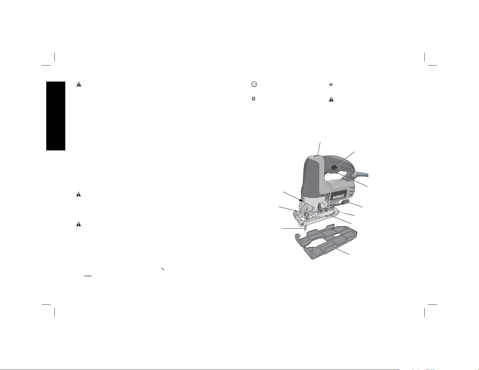
DESCRIPTION (FIG. 1)
WARNING: Never modify the power tool or any part of it.
Damage or personal injury could result.
A. Trigger switch G. Shoe beveling lever
B. Lock-on button H. Speed control wheel
C. Saw blade locking lever I. Cutting action lever
D. Saw blade J. LED Light
E. Shoe sleeve
F. Shoe
INTENDED USE
This jig saw is designed for professional sawing applications.
DO NOT use under wet conditions or in presence of flammable
liquids or gases.
This jig saw is a professional power tools. DO NOT let children
come into contact with the tool. Supervision is required when
inexperienced operators use this tool.
ASSEMBLY AND ADJUSTMENTS
WARNING: Prior to assembly and adjustment, ALWAYS unplug
tool.
OPERATION
WARNING: Always observe the safety instructions and applicable
regulations.
FIG. 2
Blade Installation
(Fig. 2)
1. Push the saw blade locking
lever (C) upward.
2. With teeth facing forward,
insert the shank of the saw
blade into the blade holder
as far as it will go.
C
3. Release the lever.
4. Check to ensure blade is secure before cutting.
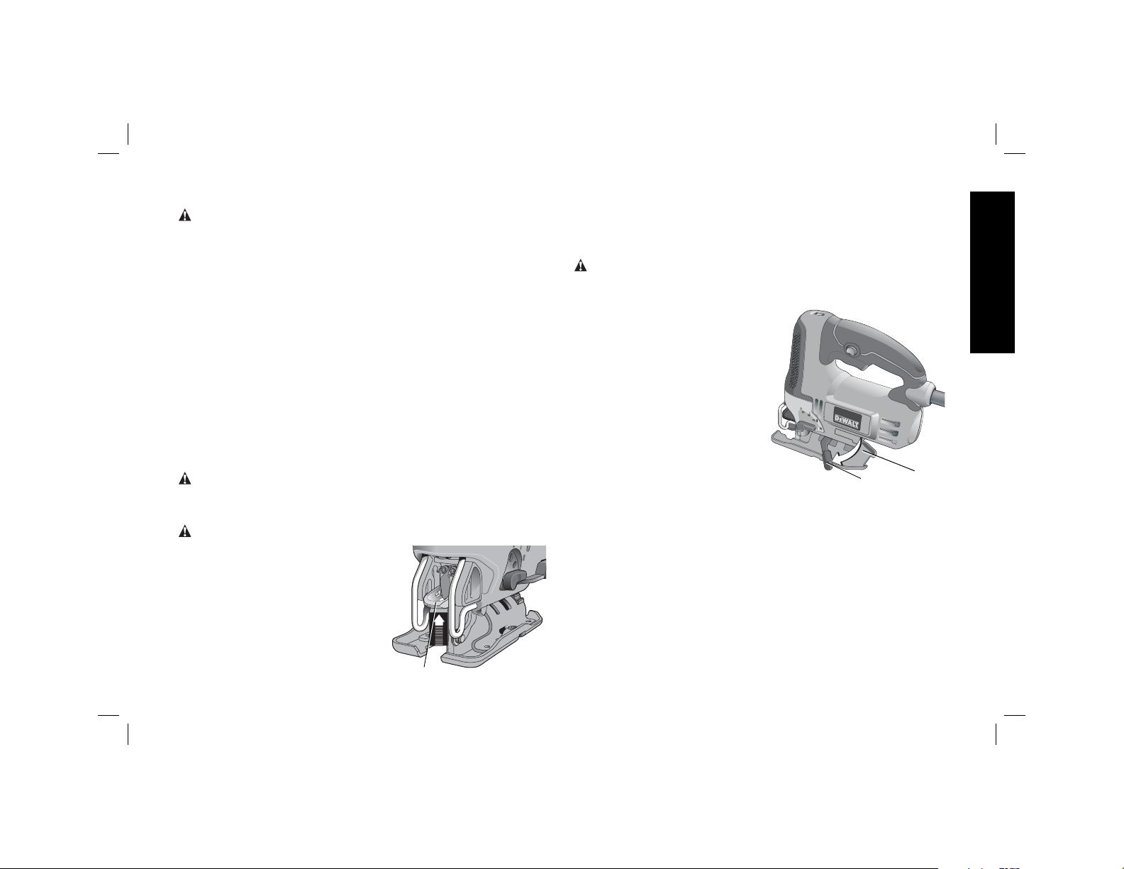
Adjusting the Shoe for Bevel Cuts
(Fig. 3)
WARNING: Never use the tool when the shoe is loose or
removed. The shoe plate can be set to a left or right bevel angle of
up to 45°.
TO SET THE BEVEL ANGLE
1. Pull the shoe beveling
lever (G) out and away
from the saw to unlock
the shoe (F) as shown
in Figure 3.
2. Slide the shoe forward
to release it from the 0°
positive stop position.
3. The shoe can be
beveled to the left or
to the right and has
detents at 15°, 30° and
45°.
4. Set the shoe to the desired bevel angle. Use a protractor to
verify angle accuracy.
5. Push the shoe beveling lever back towards the saw to lock the
shoe.
TO RESET THE SHOE FOR STRAIGHT CUTS
1. Pull the shoe beveling lever (G) out and away from the saw to
unlock the shoe (F) as shown in Figure 3.
2. Rotate shoe to an angle of approximately 0° and then pull shoe
backwards to engage the 0° positive stop.
3. Push the shoe beveling lever back towards the saw to lock the
shoe.
5
FIG. 3
G
English
F
Page 8
Switching On and Off
To switch the tool on, squeeze the trigger switch (A).
For continuous operation, squeeze the trigger switch then depress
the lock-on button (B). Once lock-on button is depressed, release
the trigger switch.
To switch the tool off, release the trigger switch. To switch the tool
off, when in continuous operation, squeeze the trigger and the lock
English
will disengage.
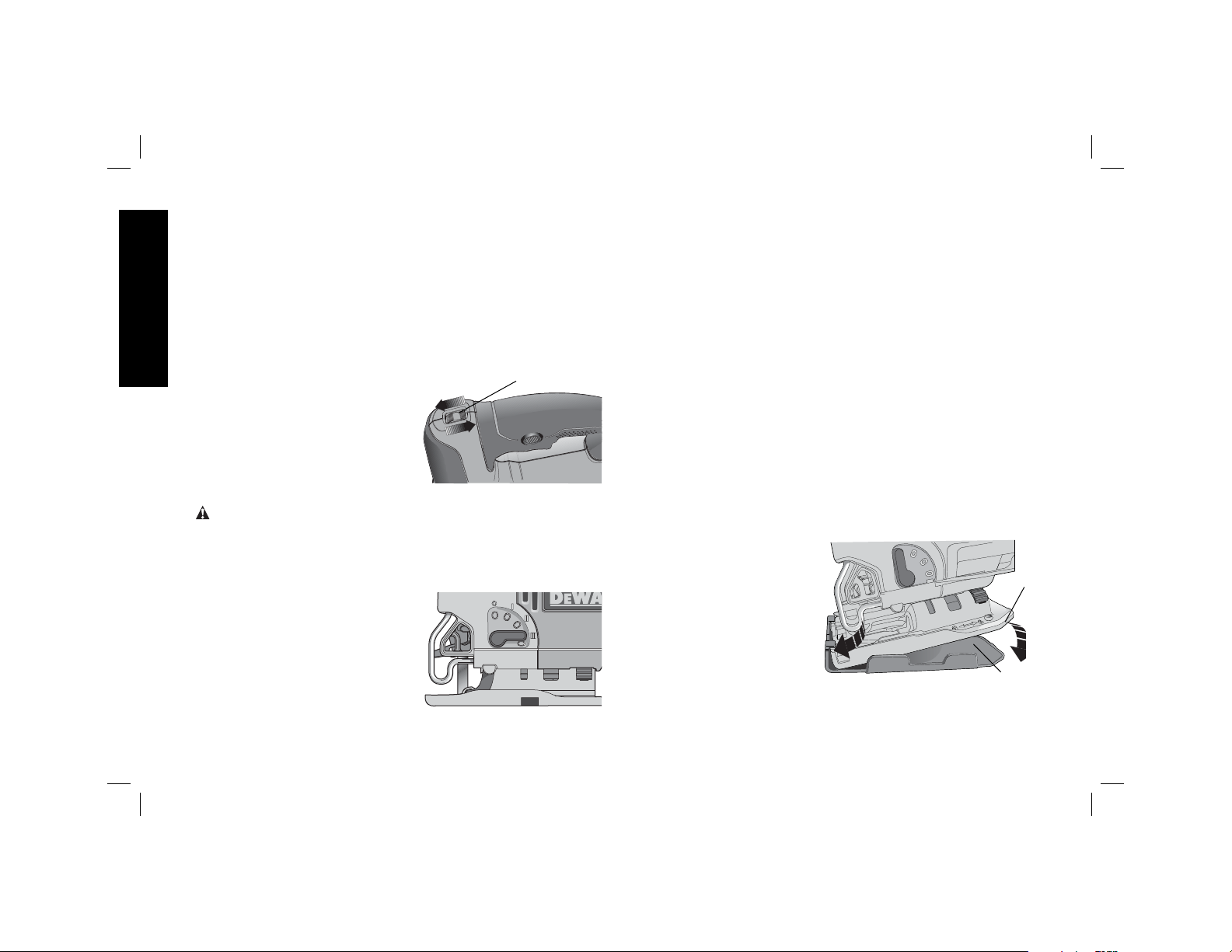
Variable Speed Control (Fig. 4)
A speed control wheel (H) is
located on the top of the saw. The
speed increases as the wheel is
turned from a low speed setting of
1 to a high speed setting of 7.
FIG. 4
H
Cutting Action –
Orbital or Straight
(Fig. 5)
WARNING: Check that the tool is not locked ON before
connecting it to a power supply. If the trigger switch is locked on
when the tool is connected to the power supply, it will start
immediately. Damage to your tool or personal injury may result.
This jig saw is equipped with
four cutting actions, three orbital
and one straight. Orbital action
has a more aggressive blade
motion and is designed for cutting
in soft materials like wood or
plastic. Orbital action provides a
faster cut, but with a less smooth
cut across the material. In orbital
action, the blade moves forward during the cutting stroke in addition
to the up and down motion.
FIG. 5
NOTE: Metal or hardwoods should never be cut in orbital action.
TO ADJUST THE CUTTING ACTION
1. Move the cutting action lever (I) between the four cutting
positions: 0, 1, 2, and 3.
2. Position 0 is straight cutting.
3. Positions 1, 2, and 3 are orbital cutting.
The aggressiveness of the cut increases as the lever is adjusted
from one to three, with three being the most aggressive cut.
LED Light
The jig saw is equipped with a light which projects on the cutting
path.
The light will come on when the trigger switch is depressed and will
go off when the trigger switch is released.
Removable Shoe Sleeve (Fig. 6)
The non-marring shoe sleeve (E) should be used when cutting
surfaces that scratch easily, such as laminate, veneer, or paint. It
can also be used to protect the shoe surface during transportation
and storage.
To attach shoe sleeve, place
the front of the shoe (F) into
the front of the shoe sleeve
(E) and lower the jig saw as
shown in Figure 6. The shoe
sleeve will click securely
onto the rear of the shoe.
To remove shoe sleeve,
grasp the sleeve from the
bottom at the two rear tabs
and pull down and away
from the shoe.
FIG. 6
F
E
6
Page 9
Hints for Optimum Use
SAWING LAMINATES
As the saw blade cuts on the upward stroke, splintering may occur
on the surface closest to the shoe plate.
– Use a fine-tooth saw blade.
– Saw from the back surface of the workpiece.
– To minimize splintering, clamp a piece of scrap wood or
hardboard to both sides of the workpiece and saw through this
sandwich.
SAWING METAL
– Be aware that sawing metal takes much more time than sawing
wood.
– Use a saw blade suitable for sawing metal.
– When cutting thin metal, clamp a piece of scrap wood to the
back surface of the workpiece and cut through this sandwich.
– Spread a film of oil along the intended line of cut for easier
operation and longer blade life. For cutting aluminum, kerosene
is preferred.
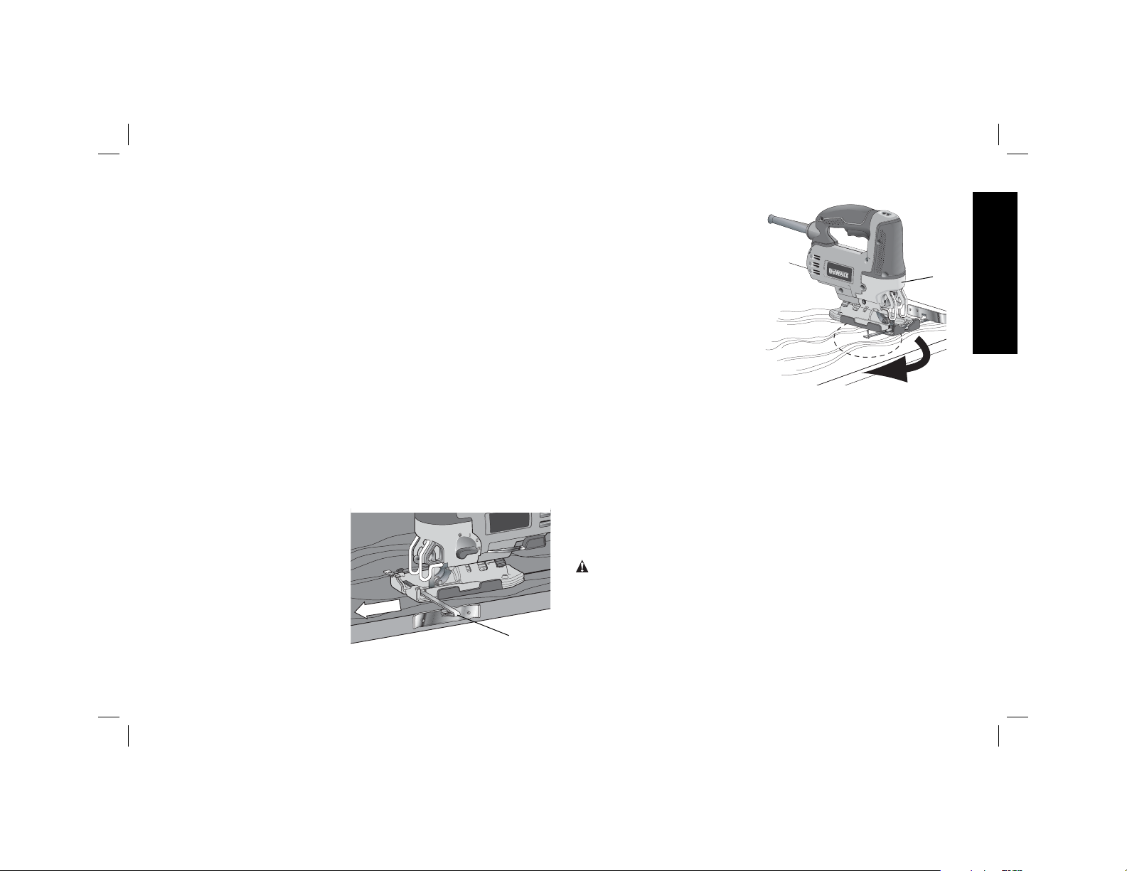
Rip/Circle Cutting (Fig. 7, 8)
Ripping and circle cutting
without a pencil line are
easily done with the rip
fence / circle guide (not
included; available at extra
cost).
Using the screw supplied
with the accessory guide,
position as shown in
Figure 7 and thread the
screw into the shoe to clamp
the fence securely.
FIG. 7
K
When ripping, position as
shown in Figure 7 and slide
the rip fence under the
screw from either side of the
saw. Set the cross bar (J) at
desired distance from blade
and tighten screw. For
ripping, the cross bar should
be down and against the
straight edge of the
workpiece as shown.
When circle cutting, adjust
rip fence so that distance
from blade to hole in fence
arm (K) is at the desired radius and tighten screw. Place saw so
that hole in fence arm is over center of circle to be cut (drill hole for
blade or cut inward from edge of material to get blade into position).
When saw is properly positioned, drive a small nail through hole in
fence arm. Using rip fence as a pivot arm, begin cutting circle. For
circle cutting, the cross bar should be up, as shown in Figure 8.
MAINTENANCE
Your DEWALT power tool has been designed to operate over a
long period of time with a minimum of maintenance. Continuous
satisfactory operation depends upon proper tool care and regular
cleaning.
WARNING: To reduce the risk of injury, turn unit off and
disconnect tool from power source before installing and removing
accessories, before making any adjustments or removing/installing
attachments or accessories.
FIG. 8
Lubrication
Your power tool requires no additional lubrication.
English
J
7
Page 10

Cleaning
WARNING: Blow dirt and dust out of the main housing with dry
air as often as dirt is seen collecting in and around the air vents.
Wear approved eye protection and approved dust mask when
performing this procedure.
WARNING: Never use solvents or other harsh chemicals for
cleaning the non-metallic parts of the tool. These chemicals may
English
weaken the materials used in these parts. Use a cloth dampened
only with water and mild soap. Never let any liquid get inside the
tool; never immerse any part of the tool into a liquid.
Accessories
WARNING: Since accessories, other than those offered by
D
EWALT, have not been tested with this product, use of such
accessories with this tool could be hazardous. To reduce the risk of
injury, only D
with this product.
Recommended accessories for use with your tool are available at
extra cost from your local dealer or authorized service center.
Volts 120V ~
Watts 500W
Hertz 50-60 Hz
RPM 0-3200/min
EWALT, recommended accessories should be used
SPECIFICATIONS
DW300-B3
8
Page 11

TROUBLESHOOTING
Problem Possible Cause Possible Solution
• Unit will not start. • Cord not plugged in.
• Circuit fuse is blown.
• Circuit breaker is tripped. • Reset circuit breaker. (If the product
• Cord or switch is damaged. • Have cord or switch replaced at a
• Plug tool into a working outlet.
• Replace circuit fuse. (If the product
repeatedly causes the circuit fuse to
blow, discontinue use immediately and
have it serviced at a D
center or authorized servicer.)
repeatedly causes thecircuit breaker to
trip,discontinue use immediately and
have it serviced at a D
center or authorized servicer.)
DEWALT Center or authorized servicer.
English
EWALT service
EWALT service
9
Page 12

Definiciones: Normas
de seguridad
Las siguientes definiciones describen el nivel de gravedad de cada
advertencia. Lea el manual y preste atención a estos símbolos.
PELIGRO:
se evita,
ADVERTENCIA:
si no se evita,
ATENCIÓN:
que, si no se evita,
moderadas.
AVISO: Se refi ere a una práctica no relacionada a lesiones
corporales que de no evitarse puede resultar en daños a la
propiedad.
ADVERTENCIA: para reducir el riesgo de lesiones, lea el
Español
manual de instrucciones.
Advertencias generales de seguridad
indica una situación de peligro inminente que, si no
provocará
la
muerte o lesiones graves.
Indica una situación de peligro potencial que,
podría
provocar la
indica una situación de peligro potencial
puede
muerte o lesiones graves.
provocar
lesiones leves o
para las herramientas eléctricas
ADVERTENCIA: Lea todas las advertencias de seguridad e
instrucciones.
instrucciones puede provocar descargas eléctricas, incendios o
lesiones graves.
El término “herramienta eléctrica” incluido en todas las advertencias
se refiere a su herramienta eléctrica conectada a la red (cable
eléctrico) o a su herramienta eléctrica accionada con baterías
(inalámbrica).
El incumplimiento de las advertencias o
GUARDE LAS ADVERTENCIAS E
INSTRUCCIONES PARA PODER
CONSULTARLAS EN EL FUTURO
1) SEGURIDAD DEL ÁREA DE TRABAJO
a) Mantenga el área de trabajo limpia y bien iluminada. Las
áreas abarrotadas u oscuras propician accidentes.
b) No haga funcionar las herramientas eléctricas en
atmósferas explosivas, como ambientes donde haya
polvo, gases o líquidos inflamables. Las herramientas
eléctricas originan chispas que pueden encender el polvo o
producir humo.
c) Mantenga alejados a los niños y a los espectadores de la
herramienta eléctrica en funcionamiento. Las distracciones
pueden provocar la pérdida de control.
2) SEGURIDAD ELÉCTRICA
a) Los enchufes de la herramienta eléctrica deben adaptarse
a la toma de corriente. Nunca modifique el enchufe de
ninguna manera. No utilice ningún enchufe adaptador
con herramientas eléctricas con conexión a tierra. Los
enchufes no modificados y que se adaptan a las tomas de
corrientes reducirán el riesgo de descarga eléctrica.
b) Evite el contacto corporal con superficies con toma de
tierra como, por ejemplo, tuberías, radiadores, cocinas y
refrigeradores. Existe mayor riesgo de descarga eléctrica si
su cuerpo está puesto a tierra.
c) No exponga las herramientas eléctricas a la lluvia ni a
condiciones de humedad. Si entra agua en una herramienta
eléctrica, aumentará el riesgo de descarga eléctrica.
d) No use el cable indebidamente. Nunca utilice el cable para
transportar, tirar o desenchufar la herramienta eléctrica.
Mantenga el cable alejado del calor, el aceite, los bordes
afilados o las piezas móviles. Los cables dañados o
enredados aumentan el riesgo de descarga eléctrica.
e) Al operar una herramienta eléctrica en el exterior, utilice
un cable prolongador adecuado para tal uso. Utilice un
cable adecuado para uso en exteriores a fin de reducir el
riesgo de descarga eléctrica.
10
10
Page 13

f) Si no se puede evitar el uso de una herramienta eléctrica
en una zona húmeda, utilice un dispositivo de corriente
residual (residual current device, RCD) de seguridad.
El uso de un RCD reduce el riesgo de sufrir una descarga
eléctrica.
3) SEGURIDAD PERSONAL
a) Permanezca alerta, controle lo que está haciendo y utilice el
sentido común cuando emplee una herramienta eléctrica.
No utilice una herramienta eléctrica si está cansado o
bajo el efecto de drogas, alcohol o medicamentos. Un
momento de descuido mientras se opera una herramienta
eléctrica puede provocar lesiones personales graves.
b) Utilice equipo de seguridad personal. Utilice siempre
protección ocular. El uso de equipo de seguridad, como
mascarillas para polvo, calzado de seguridad antideslizante,
cascos o protección auditiva en las condiciones adecuadas
reducirá las lesiones personales.
c) Evite poner en marcha la herramienta involuntariamente.
Asegúrese de que el interruptor está apagado antes de
conectar la fuente de alimentación y/o la batería, coger
o transportar la herramienta. Transportar herramientas
eléctricas con su dedo apoyado sobre el interruptor o
enchufar herramientas eléctricas con el interruptor en la
posición de encendido puede propiciar accidentes.
d) Retire la clavija de ajuste o la llave de tuercas antes de
encender la herramienta eléctrica. Una llave de tuercas
o una clavija de ajuste que quede conectada a una pieza
giratoria de la herramienta eléctrica puede provocar lesiones
personales.
e) No se estire demasiado. Conserve el equilibrio y
posiciónese adecuadamente en todo momento. Esto
permite un mejor control de la herramienta eléctrica en
situaciones inesperadas.
f) Use la vestimenta adecuada. No use ropas holgadas ni
joyas. Mantenga el cabello, la ropa y los guantes alejados
de las piezas en movimiento. Las ropas holgadas, las joyas
o el cabello largo pueden quedar atrapados en las piezas
en movimiento.
g) Si se suministran dispositivos para la conexión de
accesorios con fines de recolección y extracción de
polvo, asegúrese de que estén conectados y que se
utilicen correctamente. El uso del extractor de polvo puede
reducir los riesgos relacionados con el polvo.
4) USO Y MANTENIMIENTO DE LA HERRAMIENTA
ELÉCTRICA
a) No fuerce la herramienta eléctrica. Utilice la herramienta
eléctrica correcta para el trabajo que realizará. La
herramienta eléctrica correcta hará el trabajo mejor, y de un
modo más seguro, a la velocidad para la que fue diseñada.
b) No utilice la herramienta eléctrica si no puede encenderla
o apagarla con el interruptor. Las herramientas que no
puedan ser controladas con el interruptor constituyen un
peligro y deben repararse.
c) Desconecte el enchufe de la fuente de alimentación o
la batería de la herramienta eléctrica antes de realizar
cualquier ajuste, cambio de accesorios o almacenar
las herramientas eléctricas. Estas medidas de seguridad
preventivas reducen el riesgo de encender la herramienta
eléctrica de forma accidental.
d) Guarde la herramienta eléctrica que no esté en uso fuera
del alcance de los niños y no permita que otras personas
no familiarizadas con ella o con estas instrucciones
operen la herramienta. Las herramientas eléctricas son
peligrosas si son operadas por usuarios que no tienen
formación.
Español
11
11
Page 14

e) Mantenimiento de las herramientas eléctricas. Revise que
no haya piezas en movimiento mal alineadas o trabadas,
piezas rotas o cualquier otra situación que pueda afectar
el funcionamiento de las herramientas eléctricas. Si
encuentra daños, haga reparar la herramienta eléctrica
antes de utilizarla. Se producen muchos accidentes a
causa de las herramientas eléctricas que carecen de un
mantenimiento adecuado.
f) Mantenga las herramientas de corte afiladas y limpias.
Las herramientas de corte con mantenimiento adecuado y
con los bordes de corte afilados son menos propensas a
trabarse y son más fáciles de controlar.
g) Utilice las herramientas eléctricas, sus accesorios y
piezas, etc. de acuerdo con las presentes instrucciones,
teniendo siempre en cuenta las condiciones de trabajo y
el trabajo que deba llevar a cabo. El uso de la herramienta
eléctrica para operaciones diferentes de aquellas para las
que fue diseñada podría originar una situación peligrosa.
5) MANTENIMIENTO
Español
a) Solicite a una persona cualificada en reparaciones que
realice el mantenimiento de su herramienta eléctrica
y que solo utilice piezas de repuesto idénticas. Esto
garantizará la seguridad de la herramienta eléctrica.
NORMAS ESPECÍFICAS DE SEGURIDAD
Advertencias de seguridad para sierras
caladoras
• Sostenga la herramienta por sus superficies de
empuñadura aisladas cuando realice una operación
en la cual la herramienta para cortar pudiera entrar en
contacto con instalaciones eléctricas ocultas o con su
propio cable. El contacto con un cable cargado, cargará a
su vez las partes metálicas expuestas de la herramienta y
dará un golpe de corriente al operador.
• Utilice abrazaderas u otra forma práctica para asegurar
y sostener la pieza de trabajo sobre una plataforma
estable. Sostener el trabajo con la mano o contra el cuerpo
no brinda la estabilidad requerida y puede llevar a la pérdida
del control.
• Mantenga las manos lejos de las zonas de corte.
Nunca se estire por debajo del material por ningún motivo.
Sostenga la parte frontal de la sierra desde el área de
sujeción contorneada. No inserte los dedos en la zona
cercana a la hoja alternativa y a la abrazadera de la hoja.
No estabilice la sierra sujetando la zapata.
• Mantenga las hojas afiladas. Las hojas sin filo pueden
hacer que la sierra se desvíe o atasque al recibir presión.
• Al cortar tuberías o conductos, asegúrese de que no
contengan agua, cableado eléctrico, etc.
• Espere a que el motor se detenga por completo antes de
retirar la hoja del indicador de corte (la ranura creada al
cortar). Una hoja en movimiento puede hacer impacto en la
pieza de trabajo provocando la rotura de una hoja, daños en
la pieza de trabajo o pérdida de control y posibles lesiones
personales.
• Al aserrar, nunca sostenga el trabajo en la mano, en
el regazo ni contra partes del cuerpo. La sierra puede
deslizarse y la hoja puede entrar en contacto con el cuerpo,
lo que ocasionaría lesiones personales.
• Mantenga los mangos secos, limpios y sin restos de
aceite ni grasa. Éstos permitirán controlar la herramienta de
mejor manera.
• Limpie su herramienta con frecuencia, especialmente
después de un uso intensivo. A menudo se acumulan
sobre las superficies interiores polvo y suciedad que
contienen partículas metálicas, que pueden provocar riesgo
de descarga eléctrica.
12
12
Page 15

• No haga funcionar esta herramienta durante períodos
prolongados. La vibración que produce el funcionamiento
de esta herramienta puede provocar lesiones permanentes
en dedos, manos y brazos. Use guantes para proveer
amortiguación adicional, tome descansos frecuentes y limite
el tiempo diario de uso.
• Evite el contacto prolongado con el polvo procedente
del lijado, serrado, esmerilado y taladrado eléctricos, así
como de otras actividades del sector de la construcción.
Lleve ropa protectora y lave con agua y jabón las zonas
expuestas. Si permite que el polvo se introduzca en la boca
u ojos o quede sobre la piel, puede favorecer la absorción de
productos químicos peligrosos.
ADVERTENCIA: Utilice protección para los oídos durante el
uso. Bajo ciertas condiciones y duración de uso, el ruido de este
producto puede contribuir a una pérdida del uso del oído.
• Los hilos del alargador deben ser de un calibre apropiado
(AWG o American Wire Gauge) para su seguridad. Mientras
menor sea el calibre del hilo, mayor la capacidad del cable.
Es decir, un hilo calibre 16 tiene mayor capacidad que uno
de 18. Un cable de un calibre insuficiente causará una caída
en la tensión de la línea dando por resultado una pérdida de
energía y sobrecalentamiento. Cuando se utilice más de un
alargador para completar el largo total, asegúrese que los
hilos de cada alargador tengan el calibre mínimo. La tabla
siguiente muestra el tamaño correcto a utilizar, dependiendo
de la longitud del cable y del amperaje nominal de la placa de
identificación. Si tiene dudas sobre cuál calibre usar, use un
calibre mayor. Cuanto más pequeño sea el número del calibre,
más resistente será el cable.
Ténsion (Volts) Longitud del cable en metros (m)
120 - 127V 0 - 7 7 - 15 15 - 30 30 - 50
220 - 240V 0 - 15 15 - 30 30 - 60 60 - 100
Corriente
nominal
(Ampéres)
0 - 6A 1,0 1,5 1,5 2,5
6 - 10A 1,0 1,5 2,5 4,0
10 - 12A 1,5 1,5 2,5 4,0
12 - 16A 2,5 4,0 No recomendado
ADVERTENCIA: Si el enchufe o el cable de alimentación están
dañados lo debe reemplazar el fabricante o su representante o por
una persona igualmente calificada para evitar peligro.
ADVERTENCIA: Siempre use protección ocular. Todos los
usuarios y personas circunstantes deben llevar protección ocular
en conformidad con ANSI Z87.1.
ADVERTENCIA: Siempre lleve la debida protección auditiva
personal en conformidad con ANSI S12.6 (S3.19) durante el
uso de esta herramienta. Bajo algunas condiciones y duraciones
de uso, el ruido producido por este producto puede contribuir a la
pérdida auditiva.
ADVERTENCIA: Parte del polvo creado al lijar, aserruchar,
moler o perforar con máquina, así como al realizar otras actividades
de la construcción, contiene substancias químicas que se sabe
producen cáncer, defectos congénitos u otras afecciones
reproductivas. Algunos ejemplos de esas substancias químicas
son:
• plomo de pinturas a base de plomo,
• sílice cristalizado de ladrillos y cemento y otros productos de
albañilería, y
• arsénico y cromo de la madera químicamente tratada (CCA).
Sección nominal mínima del cable en
milímetros cuadrados (mm2 )
Español
13
13
Page 16

El riesgo al contacto con estas substancias varía, según la
frecuencia en que se haga este tipo de trabajo. Para reducir la
exposición a esas substancias químicas: trabaje en un área bien
ventilada, y trabaje con equipos de seguridad aprobados, tales
como máscaras contra el polvo especialmente diseñadas para filtrar
las partículas microscópicas.
• Evite el contacto prolongado con polvos originados
por lijar, aserrar, esmerilar, taladrar y otras actividades
constructivas. Vista ropas protectoras y lave las áreas
expuestas con agua y jabón. Permitir que el polvo se
introduzca en su boca, ojos, o dejarlo sobre la piel promueve la
absorción de químicos dañinos.
ADVERTENCIA: La utilización de esta herramienta puede
originar polvo o dispersarlo, lo que podría causar daños graves y
permanentes al sistema respiratorio, así como otras lesiones.
Siempre use protección respiratoria aprobada por NIOSH/OSHA,
apropiada para su uso en condiciones de exposición al polvo.
Procure que las partículas no se proyecten directamente sobre su
rostro o su cuerpo.
• La etiqueta de la herramienta puede incluir los siguientes
Español
símbolos. A continuación se indican los símbolos y sus
definiciones:
V ...........voltios A ..............amperios
Hz .........hertz W .............vatios
min ........minutos
............corriente alterna
.....corriente directa ............corriente alterna o
..........Construcción Clase I .................directa
..............(con conexión a tierra) no .............velocidad sin carga
..........Construcción Clase II .............terminal a tierra
..............(con aislamiento doble) .............símbolo de alerta
RPM ......revoluciones o
.................de seguridad
..............reciprocidad …/min ......por minuto
..............por minuto gpm/ipm...golpes por minuto
DESCRIPCIÓN (FIG. 1)
ADVERTENCIA: Nunca modifique la herramienta eléctrica ni
ninguna pieza de esta. Puede producir daños o lesiones corporales.
USO PREVISTO
Esta sierra caladora está diseñada para aplicaciones de uso
profesional.
NO USE la herramienta bajo condiciones de humedad o en
presencia de gases o líquidos inflamables.
Esta sierra caladora es una herramienta profesional. NO permita
que los niños entren en contacto con la herramienta. Cuando la
hagan funcionar operarios sin experiencia, es necesaria supervisión.
FIG. 1
J
C
D
H
B
A
G
I
F
E
14
14
Page 17

A. Interruptor disparador
B. Botón de bloqueo
C. Palanca de bloqueo de la hoja de sierra
D. Hoja de sierra
E. Manga de la zapata
F. Zapata
G. Palanca para biselado de la zapata
H. Selector de control de velocidad
I. Palanca de acción de corte
J. Luz LED
MONTAJE Y AJUSTES
ADVERTENCIA: Asegúrese de quitar la batería antes de montar
el aparato y ajustarlo. Apague siempre el aparato antes de colocar
o quitar la batería.
FUNCIONAMIENTO
ADVERTENCIA: Respete siempre las instrucciones de seguridad
y la reglamentación aplicable.
Instalación de la hoja (Fig. 2)
1. Empuje la palanca de bloqueo
de la hoja de sierra (C) hacia
arriba.
2. Con los dientes orientados
hacia adelante, introduzca el
vástago de la hoja de sierra
en el portahojas tanto como
sea posible.
3. Suelte la palanca.
4. Verifique para asegurarse de
que la hoja esté firme antes
de cortar.
FIG. 2
C
Ajuste de la zapata para Cortes en
bisel (Fig. 3)
ADVERTENCIA: Nunca utilice la herramienta si la zapata está
suelta o no está colocada. La placa de la zapata puede fijarse para
un ángulo de biselado a la derecha o a la izquierda de hasta
45 grados.
PARA ESTABLECER EL ÁNGULO DE BISEL
1. Tire de la palanca de
biselado de la zapata
(G) hacia afuera de la
sierra para desbloquear
la zapata (F), como se
muestra en la Figura 3.
2. Deslice la zapata hacia
adelante para liberarla
de la posición de tope
positiva 0 grados.
3. La zapata puede ser
biselada hacia la
izquierda o la derecha y
tiene bloqueos a 15, 30
y 45 grados.
4. Coloque la zapata en el ángulo de bisel deseado. Use un
transportador para verificar la precisión del ángulo.
5. Tire de la palanca de biselado de la zapata hacia atrás en
dirección a la sierra para bloquear la zapata.
PARA FIJAR LA ZAPATA PARA CORTES RECTOS
1. Tire de la palanca de biselado de la zapata (G) hacia afuera de
la sierra para desbloquear la zapata (F), como se muestra en
la Figura 3.
FIG. 3
G
Español
F
15
15
Page 18

2. Rote la zapata a un ángulo de 0 grados aproximadamente y
luego tire la zapata hacia atrás para fijar el tope positivo de 0
grados.
3. Tire de la palanca de biselado de la zapata hacia atrás en
dirección a la sierra para bloquear la zapata.
Encendido y apagado
Para encender la herramienta, oprima el interruptor disparador (A).
Para obtener un funcionamiento continuo, oprima el interruptor
disparador y luego el botón de bloqueo (B). Una vez que haya
oprimido el botón de bloqueo, suelte el interruptor disparador.
Para apagar la herramienta, suelte el interruptor disparador. Para
apagar la herramienta cuando está en funcionamiento continuo,
oprima el disparador y se liberará el bloqueo.
Control de velocidad variable (Fig. 4)
En la parte superior de la sierra,
encontrará una rueda de control
de velocidad (H). La velocidad
aumenta a medida que se gira la
Español
rueda desde la configuración 1
de velocidad baja a la
configuración 7 de velocidad
alta.
FIG. 4
H
Acción de corte:
Orbital o en línea recta (Fig. 5)
ADVERTENCIA: Verifique que la herramienta no esté bloqueada
antes de conectarla al suministro de energía. Si el interruptor
disparador está bloqueado cuando conecta la herramienta al
suministro de energía, la herramienta arrancará inmediatamente.
Podría provocar lesiones o daños a su herramienta.
Esta sierra caladora está equipada
con cuatro acciones de corte, tres
orbitales y uno en línea recta. La
acción orbital tiene un movimiento
de hoja más agresivo y está
diseñada para cortar materiales
blandos como la madera o el
plástico. La acción orbital
proporciona un corte más rápido,
pero un corte menos uniforme del
material. En la acción orbital, la hoja se mueve hacia adelante
durante la carrera de corte además del movimiento hacia arriba y
hacia abajo.
NOTA: Nunca debe cortar metal o maderas duras con la acción
orbital.
PARA AJUSTAR LA ACCIÓN DE CORTE
1. Mueva la palanca de acción de corte (I) entre las cuatro
posiciones de corte: 0, 1, 2 y 3.
2. La posición 0 es para cortes rectos.
3. Las posiciones 1, 2 y 3 son para cortes orbitales.
La agresividad del corte aumenta a medida que ajusta la palanca
del 1 al 3, que es el corte más agresivo.
FIG. 5
Luz LED
La sierra caladora está equipada con una luz que se proyecta
sobre el trayecto de corte.
Se encenderá la luz cuando oprima el interruptor disparador y se
apagará cundo lo libere.
16
16
Page 19

Retire la manga de la zapata
(Fig. 6)
La manga de la zapata
antirrayaduras (E) se debe
utilizar cuando corta
superficies que se rayan
con facilidad, como
laminados, hojas de madera
o pintura. Además, se puede
utilizar para proteger la
superficie de la zapata
durante el transporte y el
almacenamiento.
Para acoplar la manga de la zapata, coloque el frente de la zapata
(F) en el frente de la manga de la zapata (E) y baje la sierra
caladora, como se muestra en la Figura 6. La manga de la zapata
hará un ruido seco que indicará que está asegurada en la parte
trasera de la zapata.
Para quitar la manga de la zapata, tome la manga de la base en
las dos lengüetas traseras y tire hacia abajo y en dirección contraria
a la zapata.
FIG. 6
F
E
Sugerencia para un uso óptimo
PARA ASERRAR LAMINADOS
Como la hoja de sierra hace el corte en su trayectoria hacia arriba,
puede que la superficie más cercana a la platina se astille.
– Use una hoja de dientes afinados.
– Haga el aserrado desde la superficie posterior de la pieza de
corte.
– A fin de minimizar el astillado, afiance un resto de madera o
madera prensada a ambos lado de la pieza de corte y proceda
a aserrar a través de esta especie de “sandwich”.
ASERRADO EN METAL
– Para empezar, recuerde que aserrar metales toma mucho más
tiempo que aserrar madera.
– Use una hoja apropiada para aserrar metales.
– En cortes de láminas delgadas, afiance un resto de madera a
la pare posterior de la pieza y corte a través de esta especie de
“sandwich”.
– Distribuya una capa de aceite a lo largo de la línea de corte
deseada para una mejor operación y una mayor duración de la
hoja. Para cortes en aluminio, coloque kerosén preferentemente.
Cortes longitudinales y cortes de
círculos (Fig. 7, 8)
Sin utilizar una línea de lápiz, el corte longitudinal y el corte de
círculos se realizan fácilmente con una guía de corte longitudinal y
una guía de círculo (no vienen incluidas; disponibles por un costo
adicional).
Utilizando el tornillo
provisto con la guía
accesoria, colóquelo como
se muestra en la Figura 7 y
enrosque el tornillo en la
zapata para ajustar bien la
guía.
Al hacer cortes
longitudinales, colóquelo
como se muestra en la
Figura 7 y deslice la guía
de corte longitudinal por debajo del tornillo desde ambos lados de
la sierra. Coloque la barra transversal (J) a la distancia deseada
con respecto a la hoja y ajuste el tornillo. Para realizar cortes
longitudinales, la barra transversal debe estar hacia abajo y contra
el borde recto de la pieza de trabajo, como se muestra.
FIG. 7
Español
K
17
17
Page 20

Al hacer cortes en círculo,
ajuste la guía de corte
longitudinal de modo que la
distancia desde la hoja hasta
el orificio del brazo de la guía
(K) sea del radio deseado, y
ajuste el tornillo. Coloque la
sierra de modo que el orificio
en el brazo de guía quede
sobre el centro del círculo que
se cortará (perfore un orificio
para la hoja o corte hacia
adentro desde el borde del
material para colocar la hoja
en posición). Cuando la sierra
esté colocada adecuadamente, deslice un clavo pequeño a través
del orificio del brazo de la guía. Con la guía de corte como brazo
giratorio, comience a cortar el círculo. Para realizar cortes de
círculos, la barra transversal debe estar levantada, como se
Español
muestra en la Figura 8.
FIG. 8
MANTENIMIENTO
Su herramienta DEWALT ha sido diseñada para funcionar
durante un largo período con un mínimo de mantenimiento.
Un funcionamiento continuo satisfactorio depende del cuidado
adecuado de la herramienta y de una limpieza periódica.
ADVERTENCIA: Para minimizar el riesgo de graves lesiones
personales, apague la herramienta y desconecte la batería
antes de realizar ajustes o quitar/instalar los acoples o accesorios.
Un encendido accidental puede causar lesiones.
Lubricación
La herramienta eléctrica no requiere lubricación adicional.
Limpieza
ADVERTENCIA: Sople la suciedad y el polvo de la carcasa
principal con aire seco siempre que vea acumularse el polvo
alrededor de los respiraderos. Utilice protección ocular y mascarillas
antipolvo aprobadas cuando realice este procedimiento.
J
ADVERTENCIA: no use nunca disolventes ni otros agentes
químicos agresivos para limpiar las piezas no metálicas de la
herramienta. Estos agentes químicos pueden debilitar los materiales
de dichas piezas. Use un trapo humedecido sólo con agua y jabón
suave. No deje que penetre ningún líquido dentro de la herramienta
y no sumerja ninguna pieza de la herramienta en líquidos.
Accesorios
ADVERTENCIA: Dado que algunos accesorios, diferentes de
los ofrecidos por D
el empleo de tales accesorios podría constituir un riesgo. Para
reducir el riesgo de lesiones, sólo deben usarse con el producto los
accesorios recomendados D
Si desea más información sobre los accesorios adecuados,
consulte a su distribuidor.
DW300-AR DW300-B2 DW300-B2C
Volts 220 V ~ 220 V ~ 220 V ~
Potencia 500 W 500 W 500 W
Frecuencia
de operación 50 Hz 60 Hz 50 Hz
Velocidad 0-3 200/min 0-3 200/min 0-3 200/min
DW300-B3
Volts 120 V ~
Potencia 500 W
Frecuencia
de operación 50–60 Hz
Velocidad 0-3 200/min
EWALT, no se han probado con este producto,
EWALT.
Especificaciones
18
Page 21

DETECCIÓN DE PROBLEMAS
Problema Causa posible Solución posible
• La unidad no enciende. • Cable desenchufado.
• Fusible quemado.
• El interruptor automático
está activado.
• Interruptor o cable
dañado
• Enchufe el cargador en un
tomacorriente que funcione.
• Reemplace el fusible quemado. (Si
repetidamente el producto hace que el
fusible del circuito se queme, deje de
utilizarlo inmediatamente y haga que le
realicen mantenimiento en un centro de
mantenimiento D
EWALT o en un centro
de servicio autorizado.)
• Reinicie el interruptor automático. (Si
repetidamente el producto hace que el
fusible del circuito se queme, deje de
utilizarlo inmediatamente y haga que le
realicen mantenimiento en un centro de
mantenimiento D
EWALT o en un centro
de servicio autorizado.)
• Haga reparar el cable o el interruptor en
un centro de mantenimiento D
EWALT
o en un centro de mantenimiento
autorizado.
Español
19
Page 22

Definições: Diretrizes
de Segurança
As definições abaixo apresentadas descrevem o grau de
gravidade correspondente a cada palavra de advertência.
Leia cuidadosamente o manual e preste atenção a estes
símbolos.
PERIGO: Indica uma situação de risco iminente que, se
não for evitada, resultará em morte ou ferimentos graves.
AVISO: Indica uma situação de risco potencial que, se não
evitada, poderá resultar em morte ou ferimentos graves.
CUIDADO: Indica uma situação de risco potencial que,
se não evitada, poderá resultar em ferimentos leves ou
moderados.
AVISO: Se refere a uma prática não relacionada a lesões
corporais que se não evitadas podem resultar em danos
materiais.
AVISO: para reduzir o risco de ferimentos, leia o manual de
instruções.
Regras Gerais de Segurança
AVISO! Leia todas as instruções. Falha no seguir de todas as
instruções listadas abaixo pode resultar em choque elétrico,
fogo e/ou em ferimento sério.
GUARDE ESTAS INSTRUÇÕES
O termo "ferramenta" em todos os avisos listados abaixo referemse a ferramenta alimentada através de seu cordão ou a ferramenta
operada a bateria (sem cordão).
1) ÁREA DE TRABALHO
Português
a) Mantenha a área de trabalho limpa e iluminada. As áreas
desorganizadas e escuras são um convite aos acidentes.
b) Não opere ferramentas em atmosferas explosivas, como
na presença de líquidos inflamáveis, gases ou poeira. As
ferramentas criam faíscas que podem inflamar a poeira ou os
vapores.
c) Mantenha crianças e visitantes afastados ao operar
uma ferramenta. As distrações podem fazer você perder o
controle.
2) SEGURANÇA ELÉTRICA
a) Os plugues da ferramenta devem ser compatíveis com
as tomadas. Nunca modifique o plugue. Não use nenhum
plugue adaptador com as ferramentas aterradas. Os
plugues sem modificações aliados a utilização de tomadas
compatíveis reduzirão o risco de choque elétrico
b) Evite o contato do corpo com superfícies ligadas ao terra
ou aterradas tais como as tubulações, radiadores, escalas
e refrigeradores. Há um aumento no risco de choque elétrico
se seu corpo for ligado ao terra ou aterramento.
c) Não exponha a ferramentas à chuva ou às condições
úmidas. A água entrando na ferramenta aumentará o risco
de choque elétrico.
d) Não force o cabo elétrico. Nunca use o cabo elétrico para
carregar, puxar ou o para desconectar a ferramenta da
tomada. Mantenha o cabo elétrico longe do calor, óleo,
bordas afiadas ou das partes em movimentos. Os cabos
danificados ou emaranhados aumentam o risco de choque
elétrico.
e) Ao operar uma ferramenta ao ar livre, use um cabo de
extensão apropriado para o uso ao ar livre. O uso de um
cabo apropriado ao ar livre reduz o risco de choque elétrico.
3) SEGURANÇA PESSOAL
a) Fique atento, olhe o que você está fazendo e use o bom
senso ao operar uma ferramenta. Não use a ferramenta
20
Page 23

quando você estiver cansado ou sob a influência de
drogas, álcool ou de medicamentos. Um momento de
desatenção enquanto opera uma ferramenta pode resultar
em grave ferimento pessoal.
b) Use equipamento de segurança. Sempre use óculos
de segurança. O equipamento de segurança tais como
a máscara contra a poeira, sapatos de segurança
antiderrapantes, capacete de segurança, ou protetor auricular
usados em condições apropriadas reduzirão os ferimentos
pessoais.
c) Evite acidente inicial. Assegure que o interruptor está na
posição desligada antes de conectar o plugue na tomada.
Carregar a ferramentas com seu dedo no interruptor ou
conectar a ferramenta que apresenta o interruptor na posição
“ ligado” são um convite à acidentes.
d) Remova qualquer chave de ajuste antes de ligar a
ferramenta. Uma chave de boca ou de ajuste unida a uma
parte rotativa da ferramenta pode resultar em ferimento
pessoal.
e) Não force além do limite. Mantenha o apoio e o equilíbrio
adequado todas as vezes que utilizar a ferramenta.
Isto permite melhor controle da ferramenta em situações
inesperadas.
f) Vista-se apropriadamente. Não use roupas
demasiadamente largas ou jóias. Mantenha seus cabelos,
roupas e luvas longe das peças móveis. A roupa folgada,
jóias ou cabelos longos podem ser presos pelas partes em
movimento.
g) Se os dispositivos são fornecidos com conexão para
extração e coleta de pó, assegure que estes estão
conectados e usados corretamente. O uso destes
dispositivos pode reduzir riscos relacionados a poeira.
4) USO E CUIDADOS DA FERRAMENTA
a) Não force a ferramenta. Use a ferramenta correta para
sua aplicação. A ferramenta correta fará o trabalho melhor
e mais seguro se utilizada dentro daquilo para a qual foi
projetada.
b) Não use a ferramenta se o interruptor não ligar e desligar.
Qualquer ferramenta que não pode ser controlada com o
interruptor é perigosa e deve ser reparada.
c) Desconecte o plugue da tomada antes de fazer qualquer
tipo de ajuste, mudança de acessórios ou armazenamento
de ferramentas. Tais medidas de segurança preventivas
reduzem o risco de se ligar a ferramenta acidentalmente.
d) Guarde as ferramentas fora do alcance das crianças e
não permitam que pessoas não familiarizadas com a
ferramenta ou com estas instruções operem a ferramenta.
As ferramentas são perigosas nas mãos de usuários não
treinados.
e) Manutenção das ferramentas. Cheque o desalinhamento
ou coesão das partes móveis, rachaduras e qualquer outra
condição que possa afetar a operação da ferramenta. Se
danificada, a ferramenta deve ser reparada antes do uso.
Muitos acidentes são causados pela pobre manutenção das
ferramentas.
f) Mantenha ferramentas de corte afiadas e limpas. A
manutenção apropriada das ferramentas de corte com lâminas
afiadas, tornam estas menos prováveis ao emperramento e
são mais fáceis de controlar.
g) Use a ferramenta, acessórios, suas partes etc., de acordo
com as instruções e na maneira designada para o tipo
particular da ferramenta, levando em consideração as
condições e o trabalho a ser desempenhado. O uso da
ferramenta em operações diferentes das designadas podem
resultar em situações de risco.
Português
21
Page 24

5) REPAROS
a) Tenha sua ferramenta reparada por um agente de reparos
qualificado e que somente use peças originais. Isto irá
assegurar que a segurança da ferramenta seja mantida.
REGRAS DE SEGURANÇA ESPECÍFICAS
Precauções de segurança para Serras
Tico-Tico
• Segure sempre uma ferramenta elétrica usando as
empunhaduras isoladas ao fazer um trabalho onde
a ferramenta de corte possa entrar em contato com
uma fiação oculta ou com o cabo elétrico da própria
ferramenta. O contato com um fi o “vivo” carregará as partes
metálicas expostas da ferramenta e causará um choque
elétrico no operador.
• Use morsas, braçadeiras ou qualquer maneira prática
para prender e apoiar a peça a ser trabalhada numa
bancada estável. Segurar a peça com as mãos ou contra
seu corpo faz com que a peça fi que instável e pode fazer
com que você perca o controle dela.
• Mantenha as mãos fora da área de corte. Nunca se incline
por debaixo do material por qualquer razão. Segure a a parte
frontal da serra ao agarrar a área contornada de agarre.
Não insira dedos ou polegar próximo da lâmina de vaivem
e prendedor da lâmina. Não estabilize a serra ao prender a
base.
• Mantenhas as lâminas afi adas. As lâminas sem fi o podem
fazer com que a serra se desvie ou gire se estiver sob
pressão.
• Ao cortar um tubo ou conduto verifi que se não contém
Português
água ou fi os elétricos, etc.
• Deixe que o motor pare completamente antes de retirar
a lâmina do corte (a fenda criada pelo corte). Uma lâmina
em movimento pode afetar a peça de trabalho e quebrar a
lâmina, danifi car a peça ou perder o controle e causar uma
possível lesão.
• Nunca segure o trabalho com suas mãos, colo ou contra
as peças de seu corpo ao serrar. A serra pode deslizar e
a lâmina pode entrar em contato com seu corpo e causar
lesão.
• Mantenha as empunhaduras secas, limpas e livres de
óleo, gordura ou graxa. Isto dá ao usuário um melhor
controle da ferramenta.
• Limpe sua ferramenta com frequência, especialmente
depois de uso intensivo. A poeira ou detritos com partículas
metálicas se acumulam com frequência nas superfícies
internas e podem causar risco de descarga elétrica.
• Não trabalhe com esta ferramenta durante períodos
muito longos. A vibração causada pelo funcionamento
desta ferramenta poderá causar lesões permanentes nos
dedos, mãos e braços. Use luvas para fornecer amortização
extra, faça pausas frequentes e limite o tempo diário de uso.
• Evite contato prolongado com poeira de lixagem, de
corte, de polimento, de perfuração e de outras atividades
de construção. Use roupa de proteção e lave as áreas
expostas com asbão e água. Se a poeira entrar em contato
com sua boca, olhos e pelo pode causar absorção de
produtos químicos danosos.
ATENÇÃO: Use proteção dos ouvidos apropriados durante
o trabalho. Em algumas condições e em função da duração da
utilização deste produto, o ruído do mesmo poderá contribuir para
a perda de audição.
• Para sua segurança, os cabos de extensão devem ter
um calibre adequado (AWG ou American Wire Gauge).
Quanto menor for o calibre do fio, maior será a capacidade
do cabo. Isto é, um fio de calibre 16 tem uma capacidade
22
Page 25

maior do que um fio de calibre 18. Uma extensão de menor
calibre causará uma queda de voltagem o que resultará em
perda de potência e superaquecimento da ferramenta. Ao
usar mais de uma extensão para completar o comprimento
total, tenha certeza de que os fios de cada extensão têm pelo
menos o calibre mínimo. A tabela a seguir indica o tamanho
que deve ser usado em função do comprimento do cabo e
da amperagem nominal. Em caso de dúvida, use um fio de
maior capacidade. Quanto menor o número do calibre, maior
será a capacidade do cabo.
Tensão
(Volts)
Comprimento do cabo de extensão
em Metros (m)
120 - 127V 0 - 7 7 - 15 15 - 30 30 - 50
220 - 240V 0 - 15 15 - 30 30 - 60 60 - 100
Faixa de Corrente
nominal (Ampéres)
Secção minima do cabo de exten-
são em milimetros quadrados (mm
2
)
0 - 6A 1.0 1.5 1.5 2.5
6 - 10A 1.0 1.5 2.5 4.0
10 - 12A 1.5 1.5 2.5 4.0
12 - 16A 2.5 4.0 Não Recomendado
ATENÇÃO: Use sempre uma proteção ocular. É necessário
que todos os utilizadores e pessoas presentes no local de trabalho
usem uma protecção ocular em conformidade com a norma ANSI
Z87.1.
ATENÇÃO: Use sempre proteção dos ouvidos adequadas
que seguem a norma ANSI S12.6 (S3.19)durante o uso do
equipamento. Em algumas condições e em função da duração
da utilização deste produto, o ruído do mesmo poderá contribuir
para a perda de audição.
ATENÇÃO: Alguma poeira gerada de lixagem, corte,
esmerilhamento, perfuração e outras atividades de construção
contém produtos químicos conhecidos como causadora de câncer,
anomalia de nascimento ou outra dano reprodutivo. Alguns
exemplos destes produtos químicos são:
• chumbo de tintas a base de chumbo
• sílica cristalina de tijolos e cimento e outros produtos de
construção e
• arsênico e crômio de madeira tratada quimicamente (CCA).
O risco a estas exposições variam dependendo da frequência que
executa este tipo de trabalho. Para reduzir sua exposição a estes
produtos químicos: Trabalhe em uma área bem ventilada e com
equipamento de segurança aprovado, tal como estas máscaras
de poeira que são especialmente criadas para filtrar partículas
microscópicas.
• Evite contato prolongado com poeira da lixadeira, de corte,
polimento, perfuração e outras atividades de construção.
Use roupa de proteção e lave as áreas expostas com asbão
e água. Se a poeira entrar em contato com sua boca, olhos e
pelo pode causar absorção de produtos químicos danosos.
ATENÇÃO: Usar esta ferramenta pode gerar e/ou espalhar
poeira, o que pode causar lesão respiratória permanente e séria
ou outro tipo de lesão. Use sempre proteção respiratória aprovada
pela NIOSH/OSHA para a exposição a poeira. Direcione as
partículas distante do rosto e corpo.
ATENÇÃO: Use proteção dos ouvidos apropriados durante
o trabalho. Em algumas condições e em função da duração da
utilização deste produto, o ruído do mesmo poderá contribuir para
a perda de audição.
• A etiqueta da ferramenta pode incluir os seguintes símbolos: Os
símbolos e suas definições são conforme a seguir:
V ............ volts A ............ ampéres
Hz .......... hertz W ........... watts
Português
23
Page 26

min ......... minutos ..........corrente alternada
....... corrente direta
........... construção de Classe I ........... terminal com conexão
............... (aterramento) ..............de aterramento
............ construção Classe II ........... símbolo de alerta de
............... (isolamento duplo) .......... segurança
BPM....... batimentos por minuto …/min .... revoluções ou
sfpm ......pés por minuto (sfpm)
.............. per minute (sfpm) ..............por minuto
n
o ........... velocidade sem carga
............... reciprocidade
Descrição (fig. 2)
AVISO: Nunca modifique a ferramenta eléctrica ou qualquer
uma das suas peças. Podem ocorrer danos ou lesões.
FIG. 1
J
C
D
H
Português
A. Gatilho G. Alavanca de inclinação
B. Botão de trava da base
C. Alavanca de bloqueio H. Botão de controle de velocidade
da lâmina de serra I. Alavanca de ação de corte
D. Lâmina de serra J. Luz de LED
E. Camisa da base
F. Base
FINALIDADE
Esta ferramenta foi fabricada para aplicações de corte profissionais.
NÃO utilize a ferramenta em condições de humidade, nem na
presença de líquidos ou gases inflamáveis.
Esta serra tico-tico é uma ferramenta elétrica profissional. NÃO
permita que crianças mexam na ferramenta. É necessária
B
supervisão quando operadores sem experiência utilizarem esta
ferramenta.
MONTAGEM E AJUSTES
AVISO: Antes de qualquer montagem e ajuste, desligue sempre
a ferramenta da alimentação.
A
G
I
F
FUNCIONAMENTO
AVISO: Respeite sempre as instruções de segurança e os
regulamentos aplicáveis.
AVISO: Risco de choque elétrico. Para reduzir o risco de
ferimentos graves, desligue a ferramenta e desconecte-a da
fonte de alimentação antes de fazer quaisquer ajustes ou de
remover/instalar dispositivos ou acessórios.
Instalação da Lâmina (Fig. 2)
1. Pressione a alavanca debloqueio da lâmina (C) para cima.
2. Com os dentes voltados para frente, insira a haste da serra no
prendedor da lâmina tanto quanto for possível.
E
24
Page 27

3. Libere a alavanca.
4. Verifique se a lâmina está
presa no lugar antes de cortar.
FIG. 2
Ajuste a Base para
Cortes Inclinados
(Fig. 3)
ATENÇÃO: Nunca use a
ferramenta quando a base estiver
solta ou removida. A placa da
base pode ser ajustada para um
ângulo de inclinação à direita ou
à esquerda de até 45°.
PARA DEFINIR O ÂNGULO DE INCLINAÇÃO
1. Puxe a alavanca de
inclinação da base
(G) para fora e distante
da serra para
desbloquear a base
(F), conforme mostrado
na Figura 3.
2. Deslize a base para
frente para liberar
de uma posição de
parada positiva de 0°.
3. A base pode ser
inclinada à esquerda
ou à direita e fica
bloqueada em 15°, 30°
e 45°.
4. Configure a base para o ângulo de inclinação desejado. Use
um transferidor para verificar a exatição do ângulo.
FIG. 3
C
G
F
5. Empurre a alavanca de inclinação da base em direção a serra
para bloquear a base.
PARA DEFINIR A BASE PARA CORTES RETOS
1. Puxe a alavanca de inclinação da base (G) para fora e distante
da serra para desbloquear a base (F), conforme mostrado na
Figura 3.
2. Gire a base em um ângulo de aproximadamente 0° e depois
puxe a base para trás para bloquear em uma parada positiva
de 0°.
3. Empurre a alavanca de inclinação da base em direção a serra
para bloquear a base.
Ligar e Desligar
Para ligar a ferramenta, pressione o gatilho (A).
Para a operação contínua, pressione o gatilho e depois o botão
de travamento (B). Ao pressionar o botão de travamento, libere o
gatilho.
Para desligar a ferramenta, libere o gatilho. Para desligar a
ferramenta, quando estiver em operação contínua, pressione o
gatilho e o travamento será desativado.
Gatilho de velocidade variável (Fig. 4)
Uma botão de controle de
velocidade (H) está localizado no
topo da serra. A velocidade
aumenta enquanto o botão varia
de uma configuração de
velocidade baixa de 1 a
configuração de velocidade alta
de 7.
FIG. 4
H
Português
25
Page 28

Ação de Corte – Orbital ou Reto
(Fig. 5)
ATENÇÃO: Verifique se a ferramenta não está bloqueada em ON
(LIG) antes de conectá-la na fonte de alimentação. Se o gatilho
estiver bloqueado em
fonte de alimentação, ela começará a funcionar imediatamente.
Isto poderá danificar a sua ferramenta e causar lesão pessoal.
Esta serra tico-tico está
equipada com quatro ações de
corte, três orbitais e uma reta. A
ação orbital tem um movimento de
lâmina mais agressivo e foi criada
para cortar materiais menos
resistentes, como madeira ou
plástico. A ação orbital fornece um
corte mais rápido, porém com um
corte menos preciso no material. Na ação orbital, a lâmina se move
para frente durante a batida de corte além do movimento para cima
e para baixo.
NOTA: Metal ou madeira dura nunca deve ser cortada na ação
orbital.
PARA AJUSTAR A AÇÃO DE CORTE
1. Mova a alavanca de ação de corte (I) entre as quatro posições
de corte: 0, 1, 2 e 3.
2. Posição 0 é o corte reto.
3. Posições 1, 2 e 3 são corte orbital.
A agressividade do corte aumenta enquanto a alavanca é ajustada
de um para três, com três sendo o corte mais agressivo.
ON (LIG) quando conectar a ferramenta na
FIG. 5
Luz de LED
Português
A serra tico-tico está equipada com uma luz que se projeta no
caminho do corte.
A luz será ativada quando o gatilho for pressionado e será
desativada quando o gatilho for liberado.
Camisa da Base Removível (Fig. 6)
A camisa da base de amortecimento (E) deve ser usada ao cortar
superfícies que são arranhadas facilmente, tal como laminado,
verniz ou tinta. Pode também ser usada para proteger uma
superfície de base durante o transporte e armazenagem.
Para anexar a camisa da
base, coloque a frente da
base (F) na frente da camisa
(E) e abaixe a serra,
conforme mostrado na
Figura 6. A camisa de base
ficará presa com segurança
na parte de trás da base.
Para remover a camisa de
base, segure a camisa do
fundo nas duas guias de
trás e puxe-a para distante
da base.
FIG. 6
Sugestões ideais de Uso
SERRAR LAMINADOS
Como a lâmina corta no sentido de baixo para cima, pode fazer
com que a superfície mais próxima da base rache.
– Use uma lâmina com dentes finos.
– Serre a partir da parte de trás da peça de trabalho.
– Para minimizar as rachaduras, encaixe uma peça de madeira
partida em ambos os lados da peça de trabalho.
SERRAR METAL
– Lembre-se de que serrar metal leva mais tempo do que serrar
madeira.
F
E
26
Page 29

– Use uma lâmina adequada para serrar metal.
– Ao cortar folhas metálicas finas, encaixe uma peça de madeira
partida em ambos os lados da peça de trabalho e serre entre
elas.
– Espalhe uma camada fina de óleo ao longo da linha de corte.
Recomenda-se usar querosene para cortar alumínio.
Corte Circular/Veio da madeira
(Fig. 7, 8)
Cortes transversais e
paralelos sem uma linha
riscada são facilmente feitos
com uma guia circular /
paralela (não incluído –
disponível com custo extra).
Usar um parafuso fornecido
com a guia de acessório,
posicione conforme
mostrado na Figura 7 e
enrosque o parafuso na
base para prender a topeguia com segurança.
Ao serrar, coloque conforme mostrado na Figura 7 e deslize a
tope-guia sob o parafuso de ambos os lados da serra. Defina a
barra de cruzamento (J) na distância desejada da lâmina e aperte
o parafuso. Para serrar, a barra de cruzamento deve ficar abaixo e
contra a borda reta da peça de trabalho, conforme mostrado.
Ao circundar o corte, ajuste o tope-guia para que a distância da
lâmina até o braço da guia (K) fique no raio desejado e aperte o
parafuso. Coloque a serra para que o orifício no braço da guia fique
acima do centro do círculo que será cortado (corte o orifício para a
lâmina ou corte dentro da borda do material para colocar a lâmina
na posição). Quando colocar a serra corretamente, insira um
FIG. 7
K
prego pequeno através do orifício no braço da guia. Use uma guia
como um braço de pivô e comece a cortar o círculo. Para cortar
um círculo, a barra de cruzamento deve ficar acima, conforme
mostrado na Figura 8.
MANUTENÇÃO
Esta ferramenta eléctrica DEWALT foi concebida para o servir
durante muito tempo com um mínimo de manutenção. Um
funcionamento satisfatório e longo depende de cuidados adequados
e de uma limpeza regular.
ATENÇÃO: Para reduzir o risco de lesões graves, desligue a
ferramenta e desligue a bateria antes de proceder a quaisquer
ajustes ou de remover/instalar instrumentos ou acessórios. Um
arranque acidental pode causar lesões.
Lubrificação
Esta ferramenta eléctrica não requer lubrificação adicional.
Limpeza
AVISO: Injecte ar seco para retirar a sujidade e o pó do
alojamento principal, sempre que notar uma acumulação de
sujidade nos respiradores ou em torno dos mesmos. Utilize uma
protecção adequada para os olhos e uma máscara para o pó
quando realizar esta operação.
AVISO: Nunca utilize solventes ou outros químicos agressivos
para limpar as partes não metálicas da ferramenta. Estes químicos
podem enfraquecer os materiais utilizados nestas partes. Utilize
um pano humedecido apenas com água e detergente suave.
Nunca permita que entre nenhum líquido na ferramenta; nunca
mergulhe qualquer parte da ferramenta em líquido.
Acessórios
AVISO: Uma vez que os acessórios que não sejam os
disponibilizados pela D
produto, a utilização de tais acessórios nesta ferramenta poderá
EWALT não foram testados com este
Português
27
Page 30

ser perigosa. Para reduzir o risco de lesão, deverão utilizar-se
apenas os acessórios recomendados pela D
produto.
Consulte o seu revendedor para mais informações acerca dos
acessórios adequados.
ESPECIFICAÇÕES
DW300-B2 DW300-BR
Volts 220 V ~ 127 V ~
Watts 500 W 500 W
Freqüência 60 Hz 60 Hz
GPM 0-3 200/min 0-3 200/min
EWALT com este
Português
28
Page 31

RESOLUÇÃO DE PROBLEMAS
Problema Causa possível Possível soluão
• O equipamento
não funciona.
• O cabo não foi ligado.
• O fusível está queimado.
• O disjuntor não foi desarmado. • Arme o disjuntor. (Se o fusível desarmar
• Cabo ou interruptor foi
danificado.
• Conecte a ferramenta em uma tomada
de parede.
• Substitua o fusível. (Se o fusível
queimar repetidamente, pare de usar o
equipamento imediatamente e envie-o
para reparo na assistência técnica ou
serviço autorizado D
repetidamente, pare de usar o
equipamento imediatamente e envie-o
para reparo na assistência técnica ou
serviço autorizado D
• Substitua o cabo ou interruptor na
assistência técnica ou serviço autorizado
DEWALT.
EWALT).
EWALT).
Português
29
Page 32

SOLAMENTE PARA PROPÓSITO DE ARGENTINA:
IMPORTADO POR: BLACK & DECKER ARGENTINA S.A.
PACHECO TRADE CENTER
COLECTORA ESTE DE RUTA PANAMERICANA
KM. 32.0 EL TALAR DE PACHECO
PARTIDO DE TIGRE
BUENOS AIRES (B1618FBQ)
REPÚBLICA DE ARGENTINA
NO. DE IMPORTADOR: 1146/66
TEL. (011) 4726-4400
SOLAMENTE PARA PROPÓSITO DE MÉXICO:
IMPORTADO POR: BLACK & DECKER S.A. DE C.V.
BOSQUES DE CIDROS, ACCESO RADIATAS NO. 42
3A. SECCIÓN DE BOSQUES DE LAS LOMAS
DELEGACIÓN CUAJIMALPA,
05120, MÉXICO, D.F.
TEL. (52) 555-326-7100
R.F.C.: BDE810626-1W7
IMPORTED BY/IMPORTADO POR:
BLACK & DECKER DO BRASIL LTDA.
ROD. BR 050, S/N° - KM 167
DIST. INDUSTRIAL II
UBERABA – MG – CEP: 38064-750
CNPJ: 53.296.273/0001-91
INSC. EST.: 701.948.711.00-98
S.A.C.: 0800-703-4644
MAQUINAS Y HERRAMIENTAS BLACK & DECKER CHILE S.A.
AVDA. EDUARDO FREI M. #6001 EDIFICIO 67
CONCHALI-SANTIAGO
CHILE
HECHO EN BRASIL
FABRICADO NO BRASIL
MADE IN BRAZIL
(AUG10) Part No. 90563638 DW300 Copyright @ 2010 D
The following are trademarks for one or more D
EWALT power tools: the yellow and black color scheme; the “D” shaped air intake grill;
EWALT
the array of pyramids on the handgrip; the kit box configuration; and the array of lozenge-shaped humps on the surface of the tool.
DEWALT Industrial Tool Co., 701 East Joppa Road, Baltimore, MD 21286
 Loading...