

Page 1
Please read these instructions before operating the product.
www.DEWALT.com
E
NL
GR
PT
FIN
HU
BG
LV
ES
DK
CZ
E
NO
SK
RO
LT
F
SE
RU
PT
PL
SI
EE
TR
HR
DW0165, DW0165S, DW0330S
User Manual
DW0165S
Page 2
1
2
0.000 m
0.000 m
0.000 m
0.000 m
50.0°
DW0165S
B
D
AAA
AAA
AAA
AAA
AAA
2
Figures
A
4
DW0165
4.5V DC
2
5
6
1
3
7
8
C
3
1
2
4
5
6
0.0000 m
0.0000 m
0.0000 m
0.0000 m
50.0°
Page 3
50.0°
0.0000 m
0.0000 m
0.0000 m
0.0000 m
50.0°
=
=
=
=
ft/m
Page 4
4
Figures
H
J
K
0.0000 m
0.0000 m
0.0000 m
0.7000m
50.0°
I
71.77 in
45.86 in
45.86 in
50.0°
max
min
+
0.3000 m
0.7000 m
1.0000m
50.0°
+
-
/
0.8500m
-
50.0°
0.1500 m
1.0000 m
+
-
/
Page 5
5
L
0.6000 m
0.4000 m
0.2400 m
50.0°
2
M
N
O
0.7000 m
0.6000 m
0.5000 m
0.2100 m
50.0°
3
2
0.240 m
2
+
0.210 m
0.450 m
2
50.0°
+
-
/
+/-
+/-
Page 6
6
Figures
1.0100m
2.7390 m
50.0°
2.1000 m
?
P
Q
?
R
Page 7

7
4.8270m
24.3°
0.0320 m
24.3°
?
S
T
Page 8
8
Figures
12”
12”
12”
0.00 in
12.0 in
50.0°
a
a
12”
12”
0.000 in
12.0 in
12.0 in
50.0°
a
a
12” 12”
0.000 in
12.0 in
12.0 in
50.0°
a
a
12”
U
Page 9
9
180°
90°
180°
X
15.0°
15.0°
50.0°
V
?
W
Page 10
10
E
Contents
• User Safety
• Battery Safety
• Loading Batteries
• Turning the Tool On
• Choosing the Settings
• Taking Measurements
• Calibrating the Tool
• Warranty
• Specications
• Error Codes
Retain all sections of this manual for future
reference.
User Safety
WARNING:
Carefully read the Safety Instructions and
Product Manual before using this product.
The person responsible for the product must
ensure that all users understand and adhere
to these instructions.
WARNING:
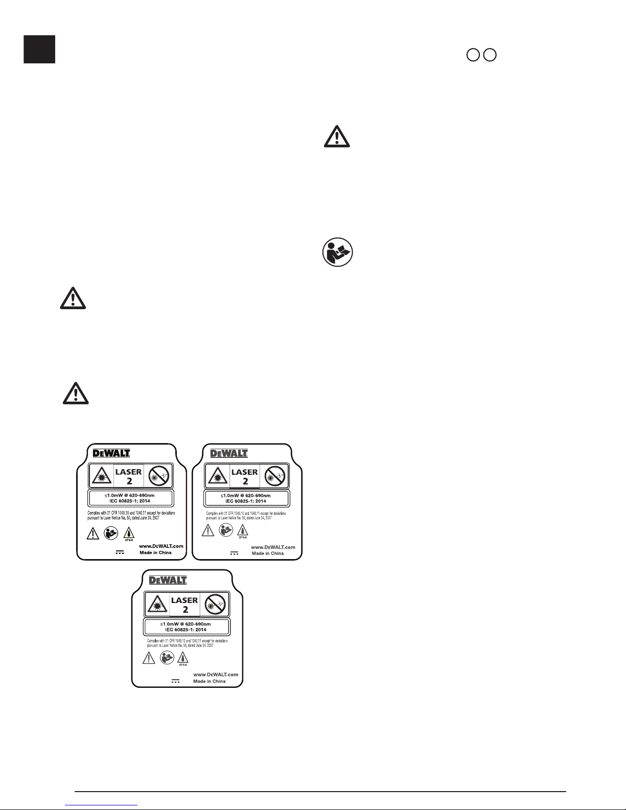
The following label information is placed on
your laser tool to inform you of the laser class
for your convenience and safety.
DW0165
4.5V DC
DW0165S
FCC ID: 2ANWF-DW0165
IC: 23237-DW0165
4.5V DC
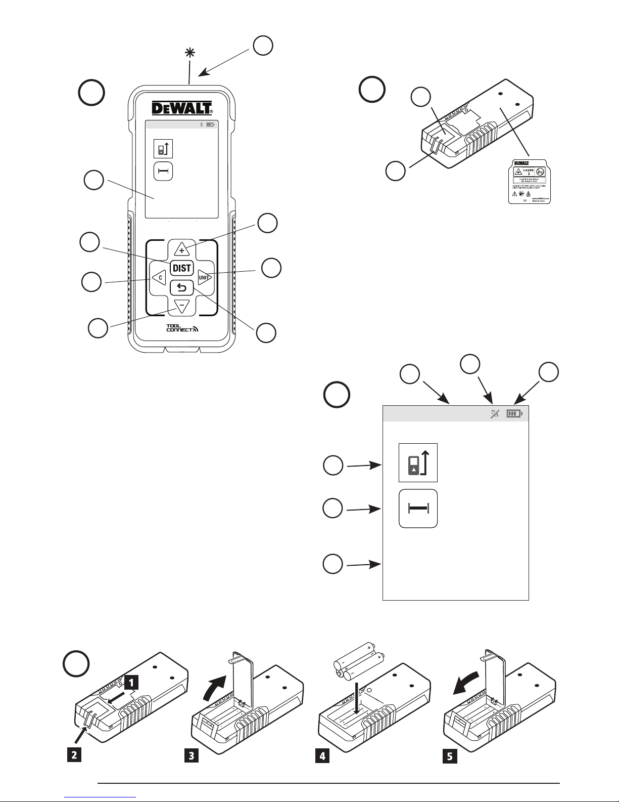
The DW0165/DW0165S/DW0330S tool emits a visible
laser beam, as shown in Figure A 1. The laser
beam emitted is Laser Class 2 per IEC 60825-1 and
complies with 21 CFR 1040.10 and 1040.11 except
for deviations pursuant to Laser Notice No. 50, dated
June 24, 2007.
WARNING:
While the laser tool is in operation, be careful
not to expose your eyes to the emitting laser
beam (red light source). Exposure to a laser
beam for an extended time period may be
hazardous to your eyes. Do not look into the
beam with optical aids.
WARNING: To reduce the risk of injury,
user must read the Product User manual,
Laser Safety manual, and Battery Safety
information.
FCC Compliance
This device complies with Part 15 of the FCC Rules.
Operation is subject to the following two conditions: (1)
This device may not cause harmful interference, and
(2) this device must accept any interference received,
including interference that may cause undesired
operation.
FCC Statement
This equipment has been tested and found to
comply with the limits for a Class B digital device,
pursuant to part 15 of the FCC rules. These limits are
designed to provide reasonable protection against
harmful interference in a residential installation. This
equipment generates, uses, and can radiate radio
frequency energy and, if not installed and used in
accordance with the instructions, may cause harmful
interference to radio communications. This device is
a portable unit. The exclusion threshold is 0.887<3.
However, there is no guarantee that interference will
not occur in a particular installation. If this equipment
does cause harmful interference to radio or television
reception, which can be determined by turning the
equipment off and on, the user is encouraged to try to
correct the interference by one or more of the following
measures:
- Reorient or relocate the receiving antenna.
- Increase the separation between the equipment and
the receiver.
- Connect the equipment into an outlet on a different
circuit (not the circuit to which the receiver is
connected).
DW0330S
FCC ID: 2ANWFDW0330
IC: 23237-DW0330
4.5V DC
Page 11
11
E
- Consult the dealer or an experienced radio/TV
technician for help.
Canada, Industry Canada (IC) Notices
Class B digital circuitry of this device complies with
Canadian ICES-003. This device complies with
Industry Canada license-exempt RSS standard(s).
Operation is subject to the following two conditions:
(1) this device may not cause interference, and (2)
this device must accept any interference, including
interference that may cause undesired operation of
the device.
Under Industry Canada regulations, the radio
transmitter(s) in this device may only operate using
an antenna of a type and maximum (or lesser) gain
approved for the transmitter by Industry Canada. To
reduce potential radio interference to other users, the
antenna type and its gain should be so chosen that
the equivalent isotropically radiated power (e.i.r.p.)
is not more than that necessary for successful
communication.
Battery Safety
WARNING: Batteries can explode or leak
and cause serious injury or re. To reduce the
risk:
ALWAYS follow all instructions and warnings
on the battery label and package.
DO NOT short any battery terminals.
DO NOT charge alkaline batteries.
DO NOT mix old and new batteries. Replace
all of them at the same time with new
batteries of the same brand and type.
DO NOT mix battery chemistries.
DO NOT dispose of batteries in re.
ALWAYS keep batteries out of reach of
children.
ALWAYS remove batteries if the device will
not be used for several months.
NOTE: Ensure that the recommended
batteries are used.
NOTE: Ensure the batteries are inserted in
the correct manner, with the correct polarity.
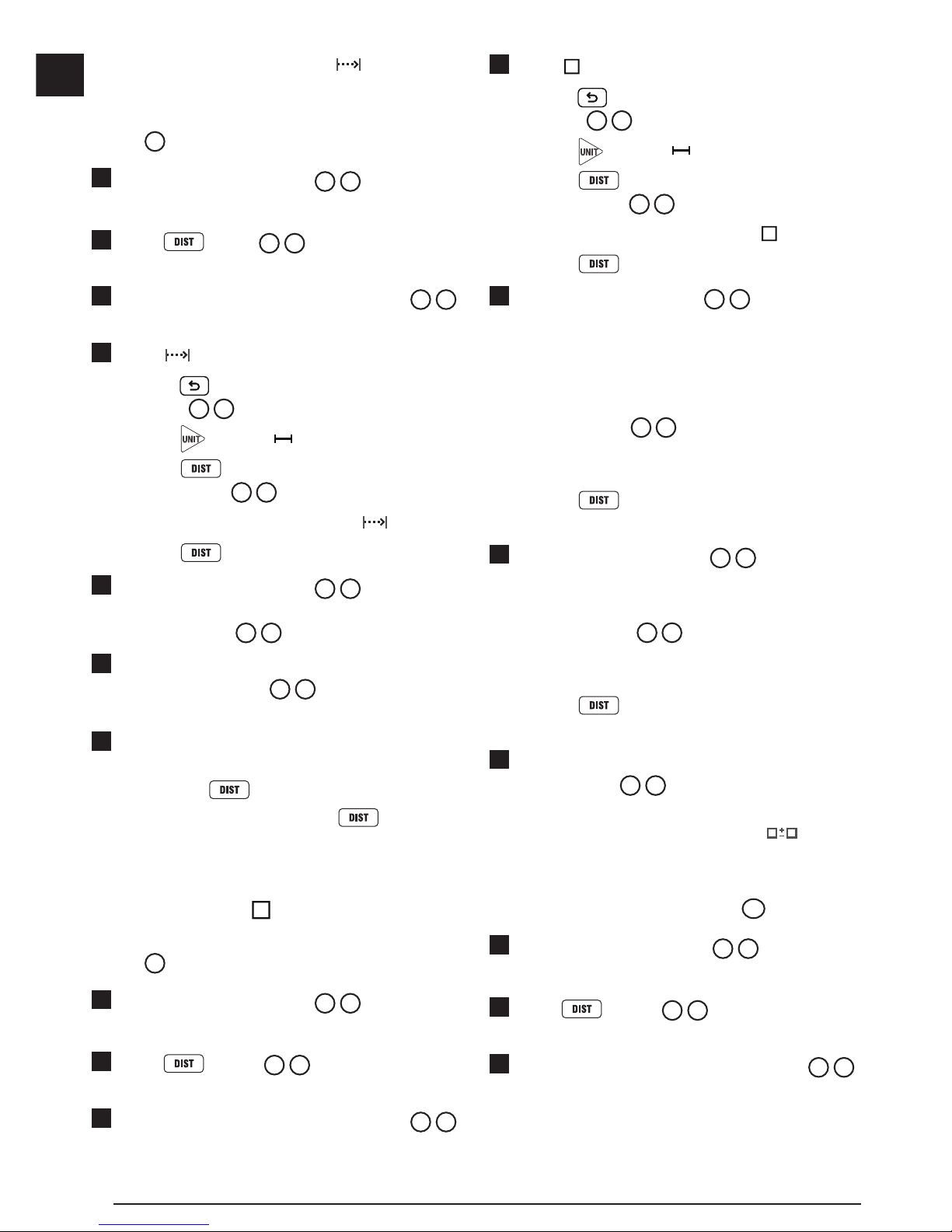
Loading Batteries
1.
Pull up the endpiece on the back of the tool
(Figure D 1).
2.
Pull up the battery compartment latch on the back
of the tool (Figure D 2 and D 3).
3.
Insert three AAA batteries, making sure to position
the - and + ends of each battery as noted inside
the battery compartment (Figure
D 4
).
4.
Push the battery door down until it snaps in place
(Figure
D 5
).
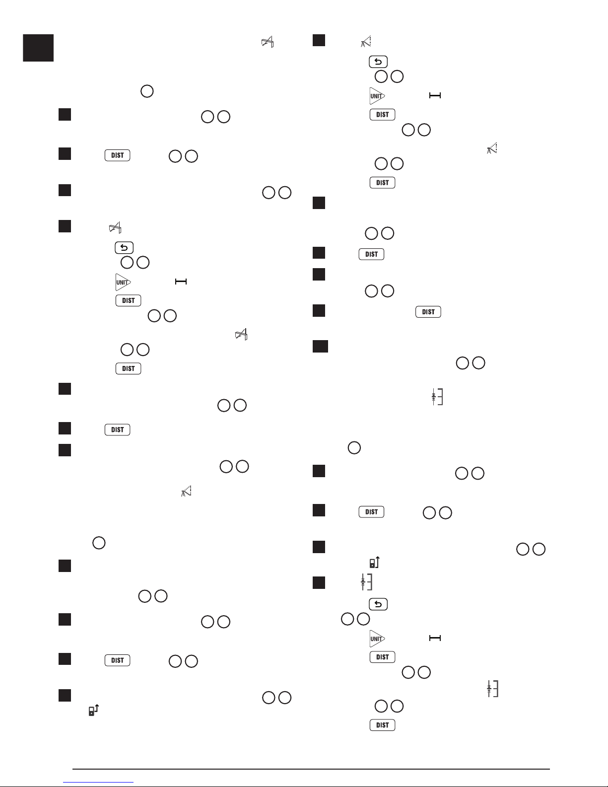
When the tool is ON, the battery level appears on the
screen (Figure
C 1
).
Turning the Tool On
1.
Point the tool's laser (Figure A 1) toward a wall
or object, and not toward anyone's eyes.
2.
Press (Figure A 3) to turn the tool on
and display the red laser dot.
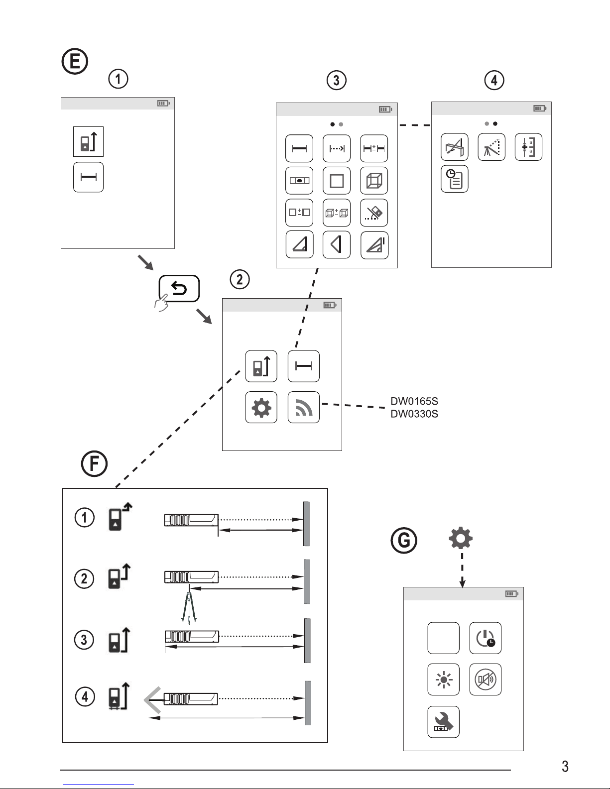
Choosing the Settings
Setting Automatic Turn Off
By default, the tool will automatically turn off
90 seconds after no buttons or options have been
selected. To change when the tool automatically turns
off, follow these steps.
1.
On the first screen (Figure E 1), press to
display the Main Menu.
2.
On the Main Menu (Figure E 2), select and
press
.
3.
On the Settings Menu (Figure G), select and
press
.
4.
Select the time.
• Choose to turn off the tool after 30 sec, 60 secs,
90 secs, or 300 secs.
• To keep the tool turned on until you manually
turn it off (by pressing and holding
for
10 seconds), select
.
5.
Press to save your setting.
Page 12
12
E
Setting Screen Brightness
By default, the tool's screen will be set at 25%
brightness. To change the brightness level, follow
these steps.
1.
On the first screen (Figure E 1), press to
display the Main Menu.
2.
On the Main Menu (Figure E 2), select and
press
.
3.
On the Settings Menu (Figure G), select and
press
.
4.
Select the desired brightness level: 25%, 50%,
75%, or 100%.
5.
Press to save your new setting.
Turning Off the Sound
By default, the tool will beep each time you take a
measurement. You can turn off the beeps.
1.
On the first screen (Figure E 1), press to
display the Main Menu.
2.
On the Main Menu (Figure E 2), select and
press
.
3.
On the Settings Menu (Figure G), select and
press
to display .
4.
Press to save your setting.
Changing the Unit of Measure
ft/m
By default, the tool will display measurements in
inches (74
9/16 in). You can change the unit of
measure to fractional ft (6'02"
9/16), meters (1.8940 m),
decimal ft (6.21 ft), or decimal inches (3.21 in).
1.
On the first screen (Figure E 1), press to
display the Main Menu.
2.
On the Main Menu (Figure E 2), select and
press
.
3.
On the Settings Menu (Figure G), select ft/m
and press
.
4.
Select the unit of measure.
• 0'00" 0/00
• 0" 0/00
• 0'00" ft
• 0.00 in
• 0.0000 m
5.
Press to save your setting.
Choosing the Tool Position
By default, distances are measured from the bottom
of the tool to a wall or object (Figure
F 3
). To
measure distances from a different tool location, follow
these steps.
1.
On the first screen (Figure E 1), press to
display the Main Menu.
2.
On the Main Menu (Figure E 2), select and
press
.
3.
Select the tool position.
• To measure from the top of the tool
(Figure
F 1
), select .
• To measure from the tripod connection on the
tool (Figure
F 2
), select .
• To measure from a corner or another hard-toreach location with the endpiece flipped open
(Figure
D 1
), select (Figure F 4) to
measure from the end of the endpiece.
4.
Press to save your new setting.
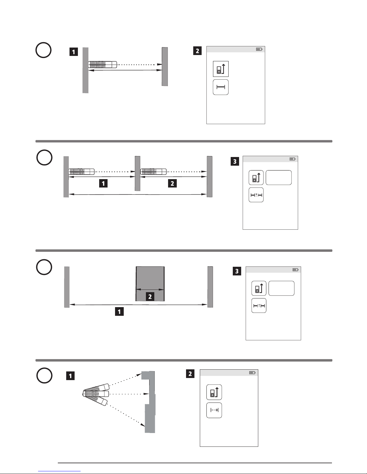
Taking Measurements
Measuring Distance
1.
Point the tool's laser (Figure A 1) toward a wall
or object, and not toward anyone's eyes.
2.
Press (Figure A 3) to turn the tool on
and display the red laser dot.
3.
Make sure the tool position setting (Figure C 4)
is correct for taking the measurement.
4.
Point the tool's laser (Figure A 1) toward
the wall or object whose distance you need to
measure (Figure
H 1
).
Page 13
13
E
5.
Press to measure the distance from the
tool to the wall or object.
6.
At the bottom of the screen, view the current
measurement (Figure H 2).
To take a new measurement, press
to move
the current measurement up to the previous line on
the screen. Then repeat steps 4-6.
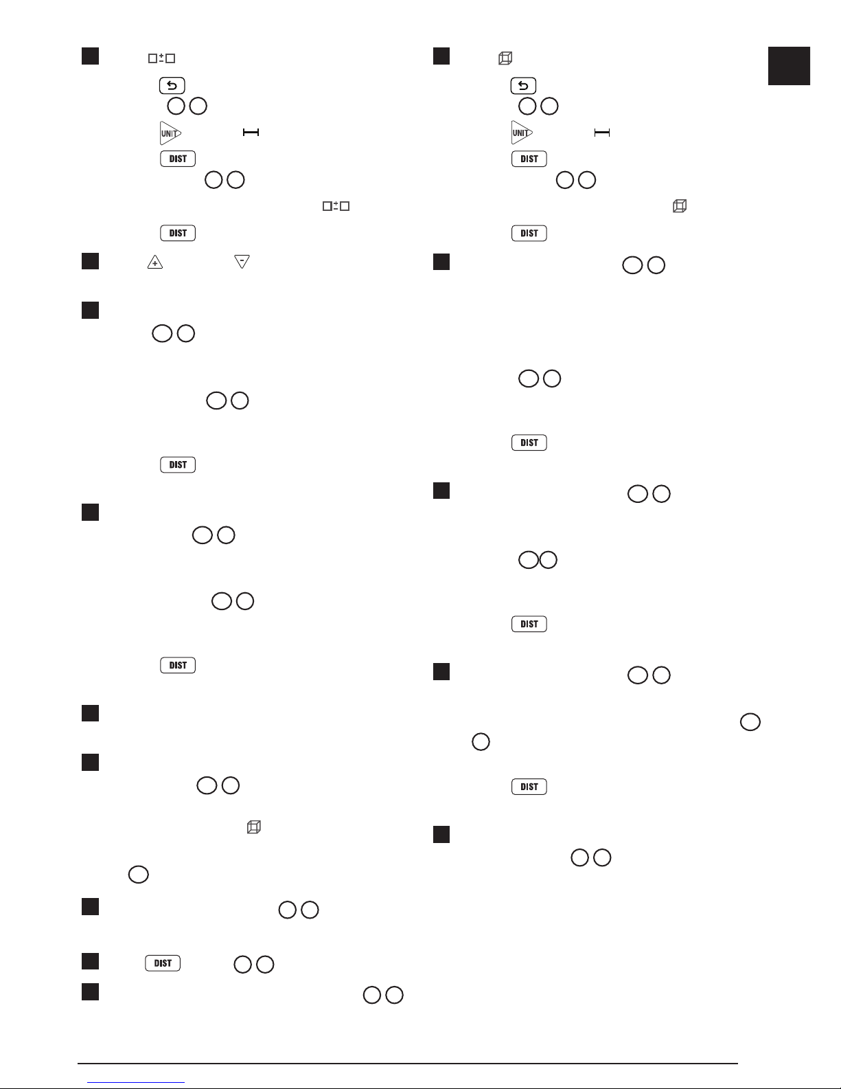
Adding 2 Measurements
You can add two measurements to get a total
measurement of the two distances (Figure I).
1.
Point the tool's laser (Figure A 1) toward a wall
or object, and not toward anyone's eyes.
2.
Press (Figure A 3) to turn the tool on
and display the red laser dot.
3.
Make sure the tool position setting (Figure C 4)
is correct for taking the measurement.
4.
Select as the measurement type.
• Press
to display the Main Menu
(Figure E 2)
• Press
to select .
• Press
to display the Measurement Type
Menu (Figure E 3).
• Press the arrow buttons to select
.
• Press
.
5.
Press to indicate that you want to add two
measurements.
6.
Point the tool's laser toward the wall or object
whose distance you need to measure
(Figure
I 1
).
7.
Press to measure the distance from the
tool to the first wall or object.
8.
Point the tool's laser toward the next wall or object
(Figure I 2).
9.
Press to measure the distance and add it
to the previous measurement.
10.
View the total of the two measurements at the
bottom of the screen (Figure I 3).
Subtracting 2 Measurements
You can subtract one measurement from another
(Figure
J
).
1.
Point the tool's laser (Figure A 1) toward a wall
or object, and not toward anyone's eyes.
2.
Press (Figure A 3) to turn the tool on
and display the red laser dot.
3.
Make sure the tool position setting (Figure C 4)
is correct for taking the measurement.
4.
Select as the measurement type.
• Press
to display the Main Menu
(Figure E 2).
• Press
to select .
• Press
to display the Measurement Type
Menu (Figure
E 3
).
• Press the arrow buttons to select
.
• Press
.
5.
Press to indicate that you want to subtract
one measurement from another.
6.
Point the tool's laser toward the wall or object
whose distance you need to measure
(Figure
J 1
).
7.
Press to measure the distance from the
tool to the wall or object.
8.
Point the tool's laser toward the wall or object
whose distance is to be subtracted from the first
measurement (Figure
J 2
).
9.
Press to measure the distance and
subtract it from the previous measurement.
10.
View the difference between the two
measurements at the bottom of the screen
(Figure
J 3
).
Page 14
14
E
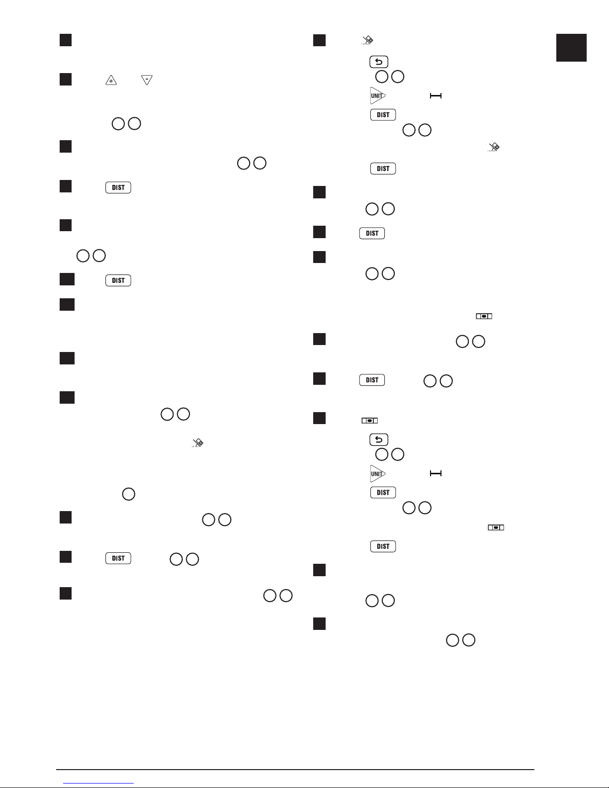
Measuring Continuously
To take a series of measurements as you move
around, change to Continuous Measure mode
(Figure
K
).
1.
Point the tool's laser (Figure A 1) toward a wall
or object, and not toward anyone's eyes.
2.
Press Figure A 3) to turn the tool on
and display the red laser dot.
3.
Make sure the tool position setting (Figure C 4)
is correct for taking the measurement.
4.
Select as the measurement type.
• Press
to display the Main Menu
(Figure E 2).
• Press
to select .
• Press
to display the Measurement Type
Menu (Figure E 3).
• Press the arrow buttons to select
.
• Press
.
5.
Point the tool's laser (Figure A 1) toward
the wall or object whose distance you need to
measure (Figure
K 1
).
6.
At the bottom of the screen, view the current
measurement (Figure K 2), which will keep
changing as you move the tool.
7.
To take the current measurement (from the tool to
the wall or object) and exit Continuous Measure
mode, press
.
To take a new measurement, press
to move
the current measurement up to the previous line on
the screen. Then repeat steps 4-7.
Measuring Area
You can measure the area of a wall, floor, or object
(Figure L).
1.
Point the tool's laser (Figure A 1) toward a wall
or object, and not toward anyone's eyes.
2.
Press (Figure A 3) to turn the tool on
and display the red laser dot.
3.
Make sure the tool position setting (Figure C 4)
is correct for taking the measurement.
4.
Select as the measurement type.
• Press
to display the Main Menu
(Figure E 2).
• Press
to select .
• Press
to display the Measurement Type
Menu (Figure E 3).
• Press the arrow buttons to select
.
• Press
.
5.
Measure the width (Figure L 1).
• Point the top of the tool at one side of the wall,
floor, or object.
• Position the tool at one end of the wall, floor,
or object and point the laser dot across the
width. (Figure
L 1
shows where to position
the tool if you are measuring from the bottom
of the tool.)
• Press
to display the width measurement
at the top of the screen.
6.
Measure the length (Figure L 2).
• Position the tool at one end of the wall, floor,
or object and point the laser dot across the
length. (Figure
L 2
shows where to position
the tool if you are measuring from the bottom
of the tool.)
• Press
to display the length measurement
on the second line of the screen.
7.
View the Area measurement at the bottom of the
screen (Figure L 3).
Adding/Subtracting 2 Areas
You can measure the area of a wall, floor, or object
and then add it to, or subtract it from, the area of
another wall, floor, or object (Figure M).
1.
Point the tool's laser (Figure A 1) toward a wall
or object, and not toward anyone's eyes.
2.
Press (Figure A 3) to turn the tool on
and display the red laser dot.
3.
Make sure the tool position setting (Figure C 4)
is correct for taking the measurement.
Page 15
15
E
4.
Select as the measurement type.
• Press
to display the Main Menu
(Figure E 2).
• Press
to select .
• Press
to display the Measurement Type
Menu (Figure E 3).
• Press the arrow buttons to select
.
• Press
.
5.
Press to add, or to subtract, the areas of
two walls, floors, or objects.
6.
Measure the width of the first wall, floor, or object
(Figure M 1).
• Position the tool at one end of the wall, floor,
or object and point the laser dot across the
width. (Figure
M 1
shows where to position
the tool if you are measuring from the bottom
of the tool.)
• Press
to display the width measurement
at the top of the screen.
7.
Measure the length of the first wall, floor, or
object (Figure M 2).
• Position the tool at one end of the wall, floor,
or object and point the laser dot across the
length. (Figure
M 2
shows where to position
the tool if you are measuring from the bottom
of the tool.)
• Press
to display the length measurement
on the second line of the screen.
8.
Follow the same steps to measure the width and
length of the second wall, floor, or object.
9.
View the Area measurement at the bottom of the
screen (Figure M 3).
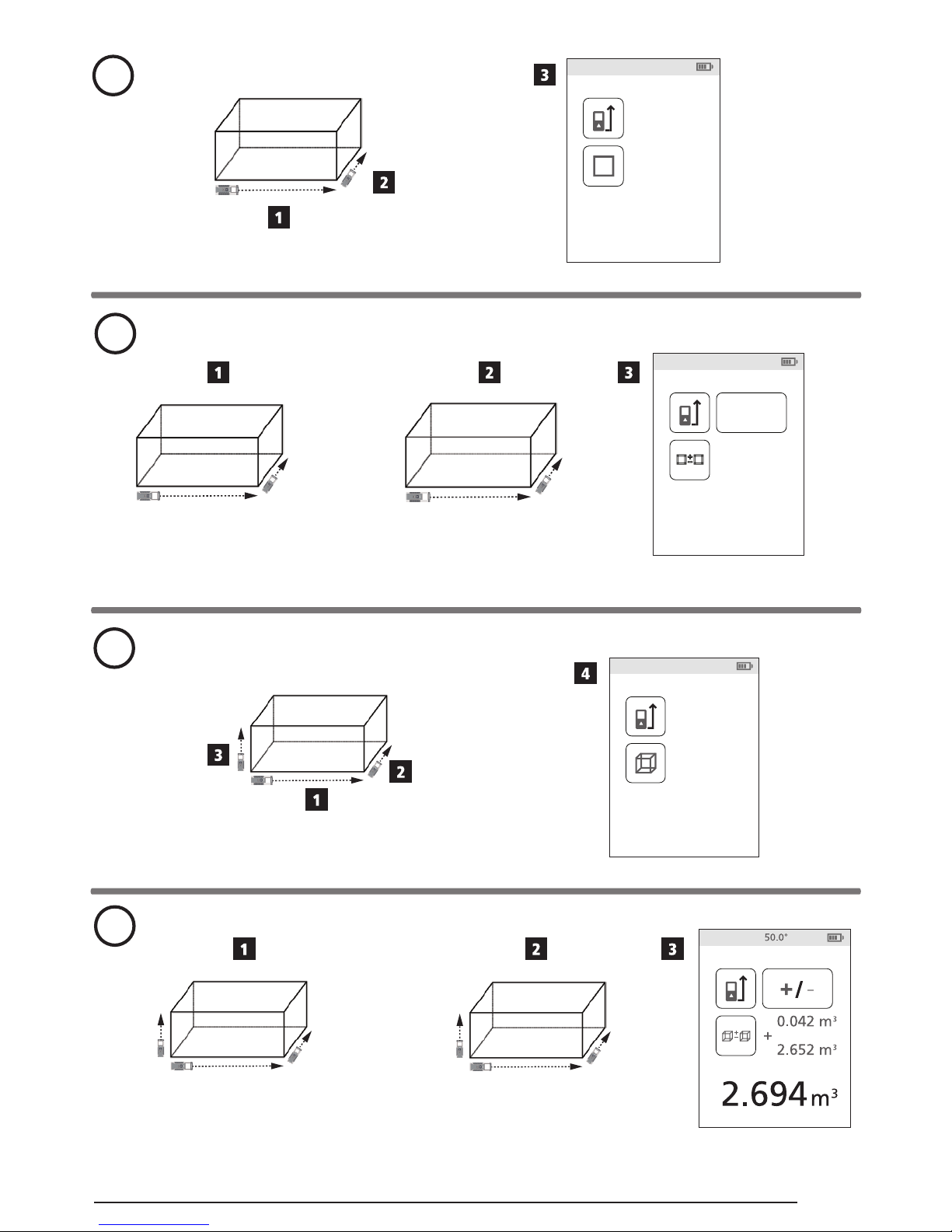
Measuring Volume
You can measure the volume of a room or object
(Figure N).
1.
Point the tool's laser (Figure A 1) toward a wall
or object, and not toward anyone's eyes.
2.
Press (Figure A 3) to turn the tool on.
3.
Make sure the tool position setting (Figure C 4)
is correct for taking the measurement.
4.
Select as the measurement type.
• Press
to display the Main Menu
(Figure E 2).
• Press
to select .
• Press
to display the Measurement Type
Menu (Figure E 3).
• Press the arrow buttons to select
.
• Press
.
5.
Measure the width (Figure N 1).
• Point the top of the tool at one side of the target
(room or object).
• Position the tool at one end of the target and
point the laser dot across the width.
(Figure
N 1
shows where to position the
tool if you are measuring from the bottom of
the tool.)
• Press
to display the width measurement
at the top of the screen.
6.
Measure the length (Figure N 2).
• Position the tool at one end of the target and
point the laser dot across the length.
(Figure
N 2
shows where to position the
tool if you are measuring from the bottom of
the tool.)
• Press
to display the length measurement
on the second line of the screen.
7
Measure the height (Figure N 3).
• Position the tool at one end of the target and
point the laser dot across the height. (Figure
N
3
shows where to position the tool if you are
measuring from the bottom of the tool).
• Press
to display the height measurement
on the third line of the screen.
8.
View the Volume measurement at the bottom of
the screen (Figure N 4).
Page 16
16
E
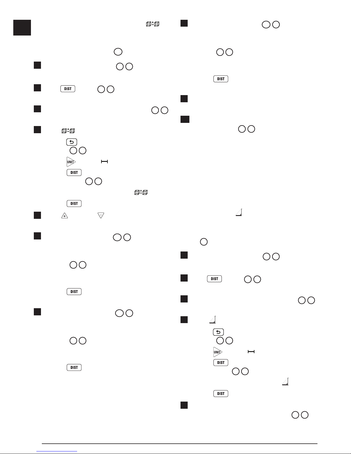
Adding/Subtracting 2 Volumes
You can measure the volume of room or object
and then add it to, or subtract it from, the volume of
another room or object (Figure
O
).
1.
Point the tool's laser (Figure A 1) toward a wall
or object, and not toward anyone's eyes.
2.
Press (Figure A 3) to turn the tool on
and display the red laser dot.
3.
Make sure the tool position setting (Figure C 4)
is correct for taking the measurement.
4.
Select as the measurement type.
• Press
to display the Main Menu
(Figure E 2).
• Press
to select .
• Press
to display the Measurement Type
Menu (Figure E 3).
• Press the arrow buttons to select
.
• Press
.
5.
Press to add, or to subtract, the volumes
of two rooms or objects.
6.
Measure the width (Figure O 1).
• Position the tool at one end of the room or
object and point the laser dot across the width.
(Figure
O 1
shows where to position the
tool if you are measuring from the bottom of
the tool.)
• Press
to display the width measurement
at the top of the screen.
7.
Measure the length (Figure O 2).
• Position the tool at one end of the room or
object and point the laser dot across the length.
(Figure
O 2
shows where to position the
tool if you are measuring from the bottom of
the tool.)
• Press
to display the length measurement
on the second line of the screen.
8.
Measure the height (Figure O 3).
• Position the tool at one end of the room or
object and point the laser dot across the height.
(Figure
O 3
shows where to position the
tool if you are measuring from the bottom of
the tool).
• Press
to display the height measurement
on the third line of the screen.
9.
Follow the same steps to measure the width,
length, and height of the second room or object.
10.
View the Volume measurement at the bottom of
the screen (Figure O 4).
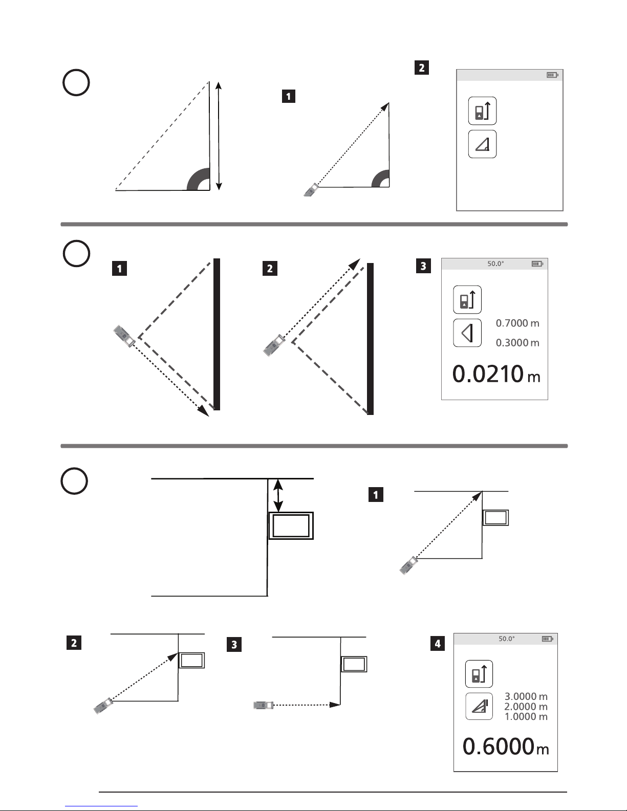
Measuring the Height of a Tall Object
If you need to measure the height of a tall object
(e.g., a tall building), you can calculate the height
based on the distance to 1 point or the distances
from the same point to 2 points on the object. The
tool will use the Pythagorean Theorem (C2=A2+B2) to
calculate the height.
Distance to 1 Point
You can use the distance to one point on a wall
or object (Indirect Height) to determine its height
(Figure P).
1.
Point the tool's laser (Figure A 1) toward a wall
or object, and not toward anyone's eyes.
2.
Press (Figure A 3) to turn the tool on
and display the red laser dot.
3.
Make sure the tool position setting (Figure C 4)
is correct for taking the measurement.
4.
Select as the measurement type.
• Press
to display the Main Menu
(Figure E 2).
• Press
to select .
• Press
to display the Measurement Type
Menu (Figure E 3).
• Press the arrow buttons to select
.
• Press
.
5.
Position the tool opposite the bottom of the
vertical height to be measured (Figure P 1).
Page 17
17
E
6.
Point the laser toward the highest point of the
building or object whose height you need to
measure (Figure
P 1
).
7.
Press to measure the distance.
8.
View the height measurement at the bottom of the
screen (Figure P 2).
Distances to 2 Points
You can use the distance to two points on a wall
or object (Double Indirect Height) to determine its
height (Figure Q).
1.
Point the tool's laser (Figure A 1) toward a wall
or object, and not toward anyone's eyes.
2.
Press (Figure A 3) to turn the tool on
and display the red laser dot.
3.
Make sure the tool position setting (Figure C 4)
is correct for taking the measurement.
4.
Select as the measurement type.
• Press
to display the Main Menu
(Figure E 2).
• Press
to select .
• Press
to display the Measurement Type
Menu (Figure E 3).
• Press the arrow buttons to select
.
• Press
.
5.
Position the tool opposite the approximate
center of the vertical height to be measured
(Figure
Q 1
).
6.
Point the laser toward the lowest point of the
building or object whose height you need to
measure (Figure
Q 2
).
7.
Press to measure the distance.
8.
From the same point, aim the laser at the
highest point of the building or object
(Figure
Q
3).
9.
Press to measure the distance.
10.
On the bottom line of the screen, view the height
of the building or object (Figure Q 4).
Measuring Partial Height of a Wall
If you need to determine the height of a section of a
wall or object (e.g., the distance from the ceiling to
the top of TV or window on the wall) (Figure
R
).
1.
Point the tool's laser (Figure A 1) toward a wall
or object, and not toward anyone's eyes.
2.
Press (Figure A 3) to turn the tool on
and display the red laser dot.
3.
Make sure the tool position setting (Figure C 4)
is correct for taking the measurement.
4.
Select as the measurement type.
• Press
to display the Main Menu
(Figure E 2).
• Press
to select .
• Press
to display the Measurement Type
Menu (Figure E 3).
• Press the arrow buttons to select
.
• Press
.
5.
Point the laser at the highest point of the wall or
object (Figure R 1).
6.
Press to measure the distance to the top
of the tall object.
7.
From the same point, aim the laser at the top
of the obstruction on the wall or object
(Figure
R
2).
8.
Press to measure the distance from the
top of the wall to the obstruction (TV, window,
etc.).
9.
From the same point, aim the laser on a
horizontal line straight ahead toward the bottom
of the wall (Figure
R
3).
10.
Press to measure the distance.
11.
On the bottom line of the screen, view the
distance between the top of the wall and the top
of the obstruction on the wall (Figure
R
4).
Page 18
18
E
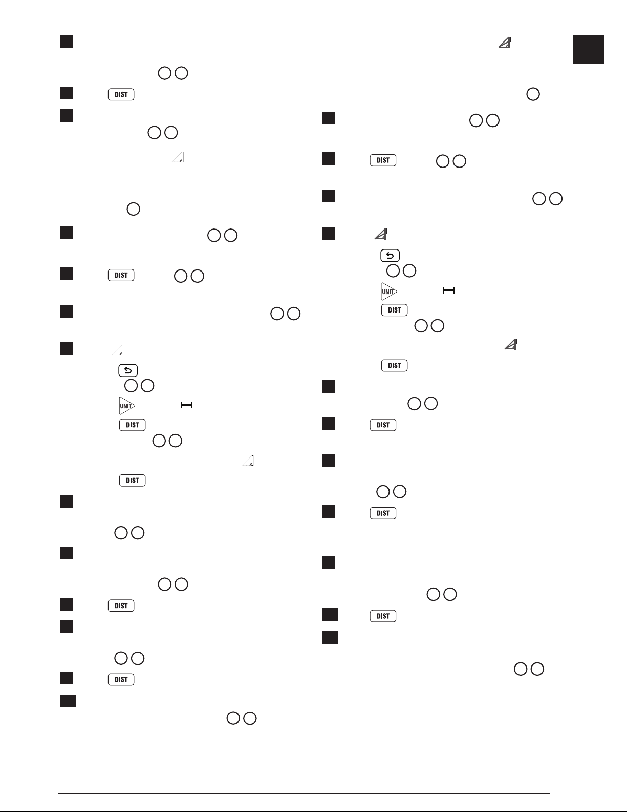
Measuring Height of Obstructed Object -
Follow these steps to determine the height of a tall
building or object that is blocked by other buildings
or objects (Figure S).
1.
Point the tool's laser (Figure A 1) toward a wall
or object, and not toward anyone's eyes.
2.
Press (Figure A 3) to turn the tool on
and display the red laser dot.
3.
Make sure the tool position setting (Figure C 4)
is correct for taking the measurement.
4.
Select as the measurement type.
• Press
to display the Main Menu
(Figure E 2).
• Press
to select .
• Press
to display the Measurement Type
Menu (Figure E 3).
• Press the arrow buttons to select
(Figure E 4).
• Press
.
5.
Point the laser at the highest point of the
building, wall, or object (Figure S 1).
6.
Press to take the measurement.
7.
On the bottom line of the screen, view the height
of the building or object (Figure S 2).
Measuring from a Tripod
If you are placing the tool on a tripod to measure
the height of a tall building, follow these steps
(Figure T).
1.
Screw the 1/4-20" hole on the back of the tool
onto the 1/4-20" connection on the top of your
tripod (Figure
T
1).
2.
Point the tool's laser (Figure A 1) toward a wall
or object, and not toward anyone's eyes.
3.
Press (Figure A 3) to turn the tool on
and display the red laser dot.
4.
Make sure the tool position setting (Figure C 4)
is to measure from the tripod connection.
5.
Select as the measurement type.
• Press
to display the Main Menu
(Figure E 2).
• Press
to select .
• Press
to display the Measurement Type
Menu (Figure E 3).
• Press the arrow buttons to select
(Figure E 4).
• Press
.
6.
Point the laser at the lowest point of the wall or
object whose height you need to measure
(Figure
T
2).
7.
Press to take the measurement.
8.
Point the laser at other points on the wall or object
(Figure T 3).
9.
When ready, press to take the
measurement.
10.
On the bottom line of the screen, view the height
of the wall or object (Figure T 4).
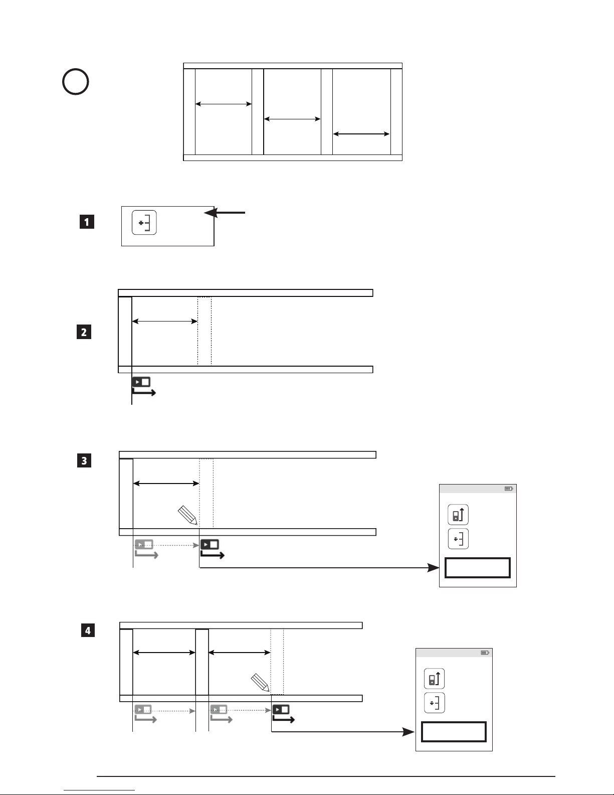
Positioning Studs
a
a
When you are framing a wall, use the Stakeout
feature to easily mark the position of each stud
(Figure
U
).
1.
Point the tool's laser (Figure A 1) toward a wall
or object, and not toward anyone's eyes.
2.
Press (Figure A 3) to turn the tool on
and display the red laser dot.
3.
Make sure the tool position setting (Figure C 4)
is set to to measure from the back of the tool.
4.
Select
a
a
as the measurement type.
• Press
to display the Main Menu (Figure
E 2
).
• Press
to select .
• Press
to display the Measurement Type
Menu (Figure E 3).
• Press the arrow buttons to select
a
a
(Figure E 4).
• Press
.
Page 19
19
E
5.
Determine the distance between each stud, for
example, 12".
6.
Press and until the top number on the
screen is set to the distance from the right edge
of one stud to the left edge of the next (e.g., 12")
(Figure
U
1).
7.
Line up the back of the tool with the right edge of
the last stud that is nailed in (Figure U 2).
8.
Press to start measuring the distance as
you slowly move the tool to the right.
9.
Continue moving the tool to the right until the
bottom number on the screen is 0.00 in (Figure
U
3).
10.
Press to stop measuring.
11.
Using a pencil, mark the location where the left
edge of the stud should be nailed into the wall
frame.
12.
Nail the left edge of the stud at the marked
location.
13.
For each remaining stud in the wall frame, repeat
steps 7-12 (Figure U 4).
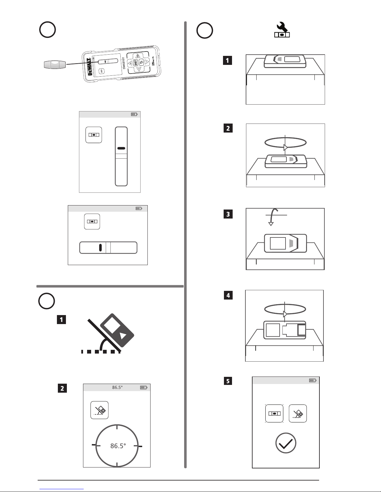
Measuring an Angle
If you need to determine the angle at which
something is positioned, use the tool to measure that
angle (Figure
W
).
1.
Point the tool's laser (Figure A 1) toward a wall
or object, and not toward anyone's eyes.
2.
Press (Figure A 3) to turn the tool on
and display the red laser dot.
3.
Make sure the tool position setting (Figure C 4)
is correct for taking the measurement.
4.
Select as the measurement type.
• Press
to display the Main Menu
(Figure E 2).
• Press
to select .
• Press
to display the Measurement Type
Menu (Figure E 3).
• Press the arrow buttons to select
.
• Press
.
5.
Position the tool at the angle to be measured
(Figure W 1).
6.
Press to take the measurement.
7.
View the angle measurement on the screen
(Figure W 2).
Using the Tool as a Level
1.
Point the tool's laser (Figure A 1) toward a wall
or object, and not toward anyone's eyes.
2.
Press (Figure A 3) to turn the tool on
and display the red laser dot.
3.
Select as the measurement type.
• Press
to display the Main Menu
(Figure E 2).
• Press
to select .
• Press
to display the Measurement Type
Menu (Figure E 3).
• Press the arrow buttons to select
.
• Press
.
4.
Place the tool in the vertical or horizontal position
on the surface that you want to check is level
(Figure
V
1).
5.
On the tool's screen, view the position of the white
bubble on the vial (Figure V 2).
Page 20
20
E
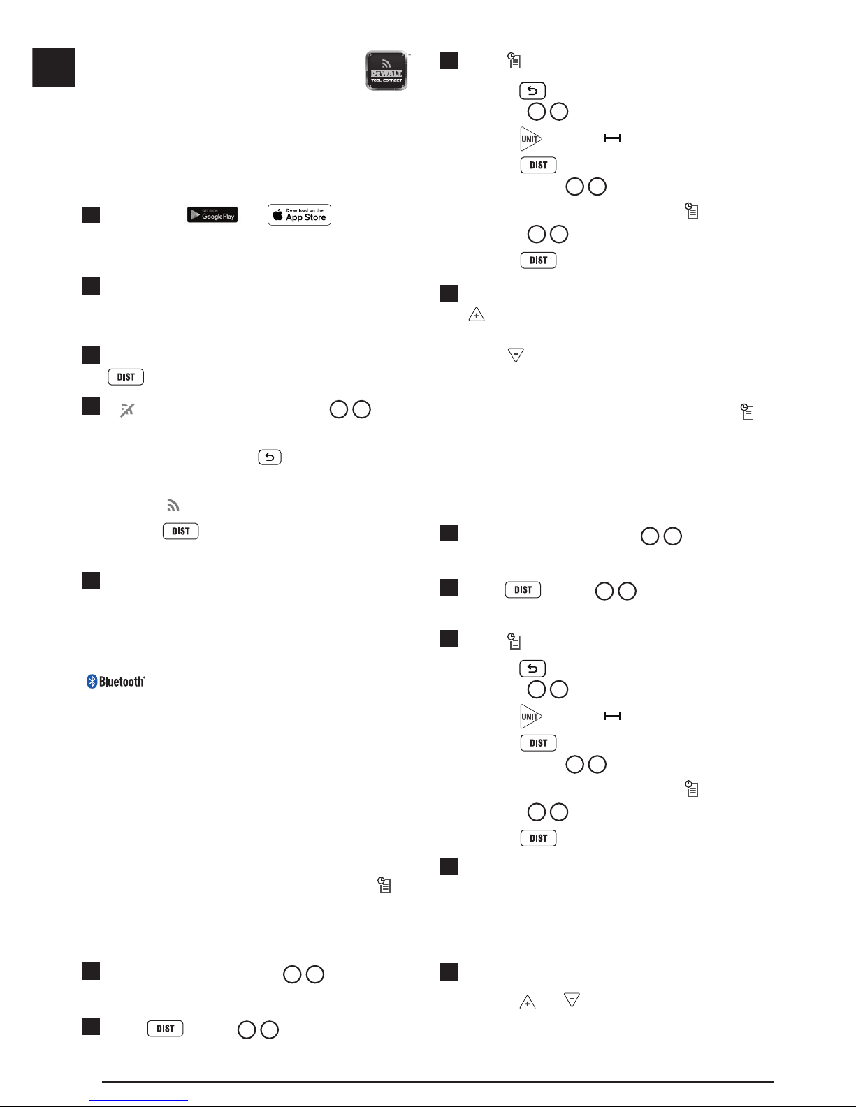
Using DW0165S/DW0330S With
If you have a DW0165S or DW0330S, you can use
its Bluetooth® capability to pair it with the DEWALT®
Tool Connect™ application on your cell phone
or tablet, and then mark up room photos with the
measurements you have taken.
1.
From either or , download
the D
EWALT
®
Tool Connect™ application to your
cell phone or tablet.
2.
Using the DEWALT® Tool Connect™ application,
capture the room or space for which you want to
record the measurements, by taking room photos.
3.
On the DW0165S or DW0330S keypad, press
to turn on the tool.
4.
If appears on the screen (Figure C 2), turn
on the Bluetooth
®
connection.
• On the keypad, press
to display the main
menu.
• Select
.
• Press
to turn on the Bluetooth®
connection.
5.
Use the DEWALT® Tool Connect™ application to
pair your cell phone or tablet to the DW0165S or
DW0330S, and then mark up room photos with
the measurements you have taken.
THE BLUETOOTH® WORD MARK AND LOGOS ARE
REGISTERED TRADEMARKS OWNED BY BLUETOOTH SIG,
INC. AND ANY USE OF SUCH MARKS BY DEWALT IS UNDER
LICENSE. APPLE AND THE APPLE LOGO ARE TRADEMARKS
OF APPLE INC., REGISTERED IN THE U.S. AND OTHER
COUNTRIES. APP STORE IS A SERVICE MARK OF APPLE
INC., REGISTERED IN THE U.S. AND OTHER COUNTRIES.
GOOGLE PLAY AND THE GOOGLE PLAY LOGO ARE TRADEMARKS OF GOOGLE INC.
Viewing the Tool's Memory
Up to the last 20 measurements are stored in the
tool's memory.
1.
Point the tool's laser (Figure A 1) toward a wall
or object, and not toward anyone's eyes.
2.
Press (Figure A 3) to turn the tool on
and display the red laser dot.
3.
Select as the measurement type.
• Press
to display the Main Menu
(Figure E 2).
• Press
to select .
• Press
to display the Measurement Type
Menu (Figure E 3).
• Press the arrow buttons to select
(Figure
E 4
).
• Press
.
4.
View the last measurement that was taken. Press
to scroll through all the measurements that
have been stored in the tool's memory (up to 20).
Press
to scroll back.
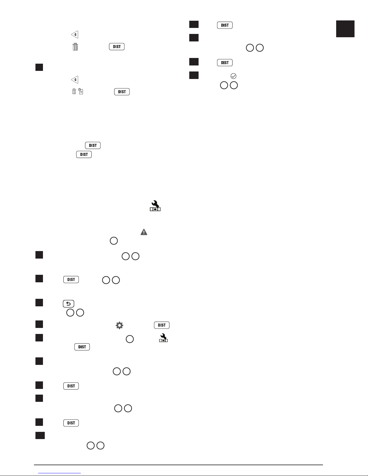
Clearing the Tool's Memory
You can clear one or more measurements that are
currently in the tool's memory.
Clearing a Measurement
1.
Point the tool's laser (Figure A 1) toward a wall
or object, and not toward anyone's eyes.
2.
Press (Figure A 3) to turn the tool on
and display the red laser dot.
3.
Select as the measurement type.
• Press
to display the Main Menu
(Figure E 2).
• Press
to select .
• Press
to display the Measurement Type
Menu (Figure E 3).
• Press the arrow buttons to select
(Figure E 4).
• Press
.
4.
Specify which measurement you want to delete:
• To delete a specific measurement, continue
with step 5.
• To delete ALL measurements, skip to step 6.
5.
To delete a specific measurement:
• Press
or to scroll through the
measurements that have been stored in the
tool's memory (up to 20) until you display the
Page 21
21
E
measurement to be deleted.
• Press
.
• Select
and press to delete the
measurement.
6.
To delete ALL measurements:
• Press
.
• Select
and press to delete all
measurements from the tool's memory.
Turning Off the Tool
The tool can be turned off in either of these ways:
• Press and hold
for 10 seconds. When
you release
after 10 seconds, the tool will
turn off.
• If you do not use the tool for 90 seconds, it will
automatically turn off.
Calibrating the tool
Please note that if you do not position the tool correctly
for each step of the calibration process,
will appear
in red on the screen (Figure X).
1.
Point the tool's laser (Figure A 1) toward a wall
or object, and not toward anyone's eyes.
2.
Press (Figure A 3) to turn the tool on
and display the red laser dot.
3.
Press to display the Main Menu
(Figure E 2).
4.
On the Main Menu, select and press .
5.
On the Settings Menu (Figure G), select
and press
.
6.
Place the tool with the screen facing upward on a
flat, level surface (Figure X 1).
7.
Press .
8.
While the tool is still laying on the level surface,
turn the tool 180° (Figure X 2).
9.
Press .
10.
Flip the long side of the tool 90° so it is laying on
its side (Figure X 3).
11.
Press .
12.
While the tool is still laying on its side, turn the
tool 180° (Figure X 4).
13.
Press .
14.
Make sure appears on the tool's screen
(Figure X 5).
Three Year Limited Warranty
DEWALT will repair, without charge, any defects due
to faulty materials or workmanship for three years
from the date of purchase. This warranty does not
cover part failure due to normal wear or tool abuse.
For further detail of warranty coverage and warranty
repair information, visit www.D
EWALT.com or call
1–800–4-D
EWALT (1–800–433–9258). This warranty
does not apply to accessories or damage caused
where repairs have been made or attempted by
others. This warranty gives you specific legal rights
and you may have other rights which vary in certain
states or provinces.
In addition to the warranty, D
EWALT
®
tools are
covered by our:
1 YEAR FREE SERVICE
DEWALT will maintain the tool and replace worn parts
caused by normal use, for free, any time during the
first year after purchase.
90 DAY MONEY BACK GUARANTEE
If you are not completely satisfied with the
performance of your D
EWALT Power Tool, Laser, or
Nailer for any reason, you can return it within 90 days
from the date of purchase with a receipt for a full
refund - no questions asked.
RECONDITIONED PRODUCT: Reconditioned product
is covered under the 1 Year Free Service Warranty.
The 90 Day Money Back Guarantee and the Three
Year Limited Warranty do not apply to reconditioned
product.
FREE WARNING LABEL REPLACEMENT: If your
warning labels become illegible or are missing, call
1-800-4-D
EWALT or visit your local service center for
a free replacement.
Page 22
22
E
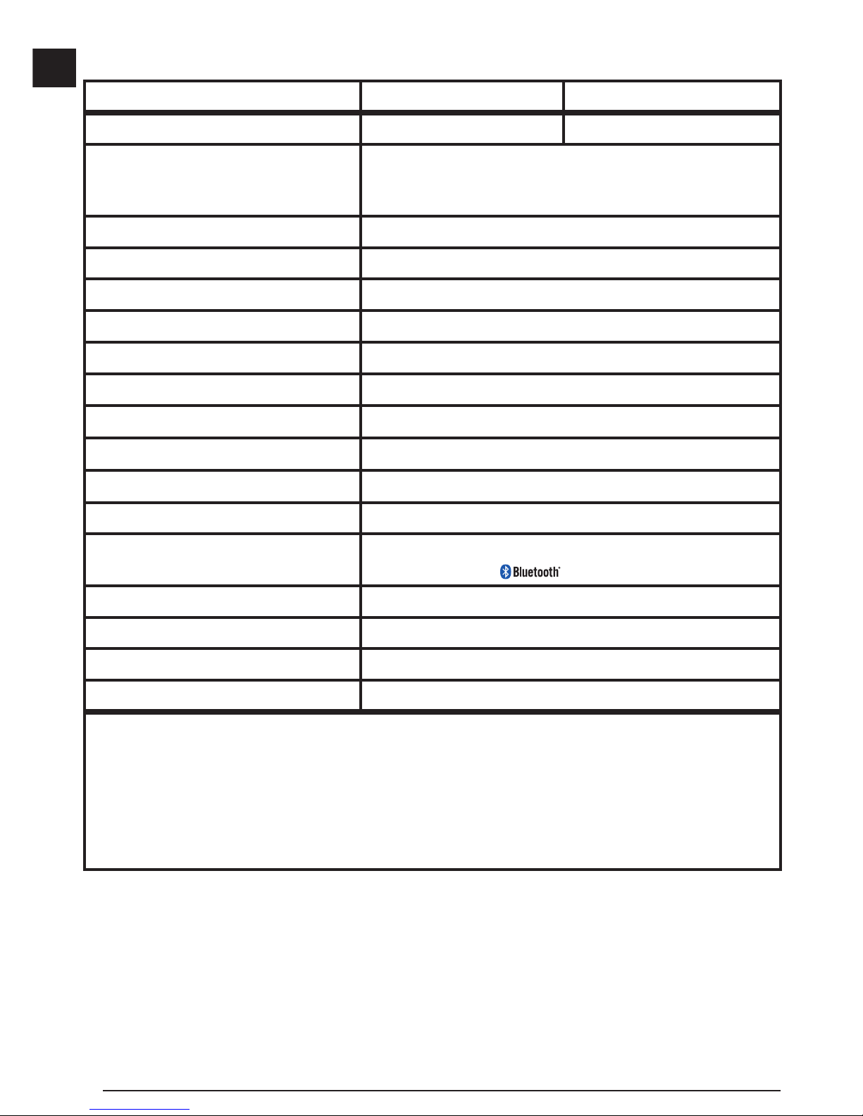
Specications
DW0165 & DW0165S DW0330S
Range 6in to 165ft (0.15m to 50m) 6in to 330ft (0.15m to 100m)
Measuring Accuracy
1
up to 10m: 1/16in (1.5mm)
10m-30m: 0.078in/5/64in) additional (+/- 0.15mm/m)
>30m: +/- 0.002in/ft (+/- 0.2mm/m)
Resolution
2
1/16in (1mm)
Laser Class Class 2 (IEC/EN60825-1: 2014)
Laser Type ≤ 1.0mW @ 630-680nm
Laser Automatic Switch-off 30s
Unit Automatic Switch-off By default, 90s. User can set to 30s, 60s, or 300s
Continuous Measuring Yes
Area Yes
Volume Yes
Pythagoras 2-Point Yes
Endpiece to measure from corners
3
Yes
Battery Life (3 x AAA) Up to 3000 Measurements
(2500 with
; DW0165S & DW0330S)
Dimension (H x D x W) 4.72 x 1.91 x 1.02in (120 x 48.5 x 26mm)
Weight (with Batteries) 9.88oz (280g)
Storage Temperature Range 14° F ~ 140° F (-10° C ~ +60 C)
Operating Temperature Range 32° F ~ 104° F (0° C ~ +40° C)
1
Measuring Accuracy depends on the current conditions:
• Under favorable conditions (good target surface and room temperature), up to 33ft (10m).
• Under unfavorable conditions (bright sunlight, a very weak reecting target surface, or large temperature uctuations), the
error can increase by to ± 0.003 in/ft (± 0.25mm/m) for distances over 33ft (10m).
2
Resolution is the nest measurement you can see. In inches, that is 1/16". In mm, that is 1mm.
3
Flip open the endpiece at the bottom of the tool when you need to t the tool into corners or grooves that are not at 180° angles. If
a corner is at 90°, the endpiece can be used to hold the tool up against something.
Page 23

Error Codes
If INFO appears on the screen with a Code number, perform the corresponding Corrective Action.
Code Description Corrective Action
101 Received Signal Too Weak,
Measuring Time Too Long
Use the target plate or change the target surface.
102 Received Signal Too High Target is too reective. Use the target plate or change the
target surface.
201 Too Much Background Light Reduce the background light on the target area.
202 Laser Beam Interrupted Remove the obstacle and repeat the measurement.
301 Temperature Too High Allow the device to cool down to a temperature within the
specied Operating Temperature Range.
302 Temperature Too Low Allow the device to warm up to a temperature within the
specied Operating Temperature Range.
401 Hardware Error Switch the device on/off several times. If the error still occurs,
return the defective device to the Service Center or distributor.
Refer to the Warranty.
402 Unknown Error Contact the Service Center or distributor. Refer to the Warranty.
500 Data Error Contact the Service Center or distributor. Refer to the Warranty.
Page 24

ES
24
Contenido
• Seguridad del usuario
• Seguridad de la batería
• Carga de baterías
• Encendido de la herramienta
• Elección de los ajustes
• Toma de mediciones
• Calibración de la herramienta
• Garantía
• Especicaciones
• Códigos de error
Conserve todas las secciones de este manual para
futura referencia.
Seguridad del usuario
ADVERTENCIA:
Lea con atención las instrucciones de
seguridad y el manual del producto antes de
usar el producto. La persona responsable
del producto debe asegurarse que todos
los usuarios entiendan y cumplan con estas
instrucciones.
ADVERTENCIA:
La siguiente etiqueta de información
se coloca en su herramienta láser para
informarle sobre la clase de láser para su
comodidad y seguridad.
DW0165
4.5V DC
DW0165S
FCC ID: 2ANWF-DW0165
IC: 23237-DW0165
4.5V DC
La herramienta DW0165/DW0165S/
DW0330S emite un rayo láser visible, como
se muestra en la Figura
A 1
. El rayo láser
emitido es un Láser Clase 2 en conformidad
con la norma IEC 60825-1 y cumple las
normas 21 CFR 1040.10 y 1040.11, excepto
en las desviaciones en conformidad con lo
establecido en Laser Notice No. 50, del 24
de junio de 2007.
ADVERTENCIA:
Mientras la herramienta láser esté en uso,
tenga cuidado de no exponer sus ojos al rayo
láser (fuente de luz roja). La exposición a un
rayo láser durante un largo periodo de tiempo
podría ser peligroso para sus ojos. No mire
directamente al rayo con ayudas ópticas.
ADVERTENCIA: Para reducir el riesgo de
lesiones, el usuario debe leer el manual de
usuario del producto, el manual de seguridad
del láser y la información de seguridad de
la batería.
Conformidad con FCC
Este dispositivo cumple con la Parte 15 del
Reglamento FCC. La operación está sujeta a las dos
condiciones siguientes: (1) Este dispositivo puede
no causar interferencia dañina, y (2) este dispositivo
debe aceptar cualquier interferencia recibida, incluso
las interferencias que pudieran causar operación no
deseada.
Declaración de FCC
Este equipo ha sido probado y cumple con los
límites para dispositivos digitales de clase B, de
conformidad con la parte 15 de las normas FCC.
Estos límites han sido diseñados para proporcionar
una protección razonable contra las interferencias
nocivas en instalaciones residenciales. Este equipo
genera, usa e irradia energía de radiofrecuencia
y, si no se instala y se usa de acuerdo con las
instrucciones, puede causar interferencia perjudicial
para las radiocomunicaciones. Este dispositivo es
una unidad portátil. El umbral de exclusión es de
0.887<3. No obstante, no existe ninguna garantía de
que no se producirá interferencia en una instalación
determinada. Si este equipo causa interferencias
perjudiciales para la recepción de radio o televisión,
que puede determinarse al encender y apagar
el equipo, el usuario puede tratar de corregir la
interferencia tomando una o varias de las siguientes
medidas:
DW0330S
FCC ID: 2ANWFDW0330
IC: 23237-DW0330
4.5V DC
Page 25

25
ES
- Reorientar o reubicar la antena receptora.
- Aumentar la distancia entre el equipo y el receptor.
- Conectar el equipo en un tomacorriente de otro
circuito diferente (no el circuito al que está conectado
el receptor).
- Consulte al vendedor o a un técnico experto en
radio/TV para solicitar su ayuda.
Canadá, Avisos del Ministerio de la Industria de
Canadá (IC)
Los circuitos digitales de clase B de este dispositivo
cumplen con la norma canadiense ICES-003. Este
dispositivo cumple las normas RSS de exención de
licencia del Ministerio de la Industria de Canadá.
La operación está sujeta a las dos condiciones
siguientes: (1) este dispositivo puede no causar
ninguna interferencia nociva, y (2) este dispositivo
debe aceptar cualquier interferencia, incluso las
interferencias que pudieran causar una operación no
deseada del dispositivo.
De conformidad con las disposiciones del Ministerio
de la Industria de Canadá, el o los radiotransmisores
de este dispositivo sólo pueden funcionar usando una
antena de un tipo y una ganancia máxima (o inferior)
aprobados para el transmisor por el Ministerio de
la Industria de Canadá. Para reducir la potencial
interferencia de radio a otros usuarios, el tipo de
antena y la ganancia deben ser elegidas para que la
potencia radiada isotrópica equivalente (p.i.r.e.) no
sea superior a la necesaria para una comunicación
correcta.
Seguridad de la batería
ADVERTENCIA: Las baterías pueden
explotar o tener fugas y causar lesiones
personales o incendios. Para reducir el
riesgo:
SIEMPRE siga todas las instrucciones y las
advertencias colocadas en las etiquetas y el
paquete de las baterías.
NO ponga en corto circuito las terminales
de la batería.
NO cargue las baterías alcalinas.
NO mezcle baterías nuevas y viejas. Cambie
todas las baterías a la vez con baterías
nuevas del mismo tipo y marca.
NO mezcle la química de las baterías.
NO deseche las baterías en fuego.
SIEMPRE mantenga las baterías fuera del
alcance de los niños.
SIEMPRE retire las baterías si el dispositivo
no va a utilizarse durante varios meses.
NOTA: Asegúrese de utilizar las baterías
recomendadas.
NOTA: Asegúrese de insertar las baterías de
manera correcta, respetando la polaridad.
Carga de baterías
1.
Jale hacia arriba la pieza de extremo en la parte
trasera de la herramienta (Figura D 1).
2.
Jale hacia arriba el seguro del compartimiento de
la batería en la parte trasera de la herramienta
(Figura
D 2
y D 3).
3.
Inserte tres baterías AAA, asegurándose de
colocar los extremos - y + de cada batería como
se indica dentro del compartimiento de la batería
(Figura
D 4
).
4.
Empuje la tapa de la batería hacia abajo hasta
que se conecte en su lugar (Figura D 5).
Cuando la herramienta esté ENCENDIDA, el nivel de
batería aparece en la pantalla (Figura
C 1
).
Encendido de la
herramienta
1.
Apunte el láser de la herramienta (Figura A 1)
hacia una pared u objeto, y no a los ojos de
nadie.
2.
Presione (Figura A 3) para encender la
herramienta y mostrar el punto láser rojo.
Page 26

ES
26
Elección de los ajustes
Ajuste de apagado automático
Por omisión, la herramienta se apaga
automáticamente 90 segundos después de que no
se haya seleccionado ningún botón u opciones.
Para cambiar cuándo se apaga la herramienta
automáticamente, siga estos pasos.
1.
En la primer pantalla (Figura E 1), presione
para mostrar el Menú principal.
2.
En el Menú principal (Figura E 2), seleccione
y presione .
3.
En el Menú de configuración (Figura G),
seleccione
y presione .
4.
Seleccione la hora.
• Elija para apagar la herramienta después de
30 seg., 60 seg., 90 seg., o 300 seg.
• Para mantener la herramienta encendida hasta
que la apague manualmente (presionando
y sosteniendo
por 10 segundos),
seleccione
.
5.
Presione para guardar sus ajustes.
Ajuste de brillo de pantalla
Por omisión, la pantalla de la herramienta se ajustará
a 25% de brillo. Para cambiar el nivel de brillo, siga
estos pasos.
1.
En la primer pantalla (Figura E 1), presione
para mostrar el Menú principal.
2.
En el Menú principal (Figura E 2), seleccione
y presione .
3.
En el Menú de configuración (Figura G),
seleccione
y presione .
4.
Seleccione el nivel de brillo deseado: 25%, 50%,
75%, o 100%.
5.
Presione para guardar su nuevo ajuste.
Apagado de Sonido
Por omisión, la herramienta hará un bip cada vez que
tome una medición. Puede apagar los sonidos de bip.
1.
En la primer pantalla (Figura E 1), presione
para mostrar el Menú principal.
2.
En el Menú principal (Figura E 2), seleccione
y presione .
3.
En el Menú de configuración (Figura G),
seleccione
y presione para mostrar
.
4.
Presione para guardar sus ajustes.
Cambio de unidad de medición
ft/m
Por omisión, la herramienta mostrará las mediciones
en pulgadas (74
9/16 pulg.). Puede cambiar la unidad
de medición a pies fraccionales (6'02"
9/16), metros
(1.8940 m), pies decimales (6.21 pies), o pulgadas
decimales (3.21 pulg.).
1.
En la primer pantalla (Figura E 1), presione
para mostrar el Menú principal.
2.
En el Menú principal (Figura E 2), seleccione
y presione .
3.
En el Menú de configuración (Figura G),
seleccione
pies/m y presione .
4.
Seleccione la unidad de medición.
• 0'00" 0/00
• 0" 0/00
• 0'00" pies
• 0.00 pulg.
• 0.0000 m
5.
Presione para guardar sus ajustes.
Page 27

27
ES
Elección de Posición de Herramienta
Por omisión, las distancias se miden desde la parte
inferior de la herramienta a una pared u objeto
(Figura F 3). Para medir distancias desde una
ubicación diferente de la herramienta, siga estos
pasos.
1.
En la primer pantalla (Figura E 1), presione
para mostrar el Menú principal.
2.
En el Menú principal (Figura E 2), seleccione
y presione .
3.
Seleccione la posición de la herramienta.
• Para medir desde la parte superior de la
herramienta (Figura
F 1
), seleccione .
• Para medir desde la conexión del trípode en
la herramienta (Figura
F 2
), seleccione .
• Para medir desde una esquina u otra ubicación
difícil de alcanzar con la pieza de extremo
abierta (Figura
D 1
), seleccione
(Figura F 4) para medir desde el extremo
de la pieza de extremo.
4.
Presione para guardar su nuevo ajuste.
Toma de Mediciones
Medición de Distancia
1.
Apunte el láser de la herramienta (Figura A 1)
hacia una pared u objeto, y no a los ojos de
nadie.
2.
Presione (Figura A 3) para encender la
herramienta y mostrar el punto láser rojo.
3.
Asegúrese que el ajuste de posición de la
herramienta (Figura C 4) sea correcto para
tomar la medición.
4.
Apunte el láser de la herramienta (Figura A 1)
hacia la pared u objeto para el que necesite medir
la distancia (Figura
H 1
).
5.
Presione para medir la distancia desde la
herramienta a la pared u objeto.
6.
En la parte inferior de la pantalla, vea la medición
actual (Figura H 2).
Para tomar una nueva medición, presione
para
mover la medición actual hasta la línea previa en la
pantalla. Repita los pasos 4-6.
Suma de 2 mediciones
Puede sumar dos mediciones para obtener la medida
total de dos distancias (Figura I).
1.
Apunte el láser de la herramienta (Figura A 1)
hacia una pared u objeto, y no a los ojos de
nadie.
2.
Presione (Figura A 3) para encender la
herramienta y mostrar el punto láser rojo.
3.
Asegúrese que el ajuste de posición de la
herramienta (Figura C 4) sea correcto para
tomar la medición.
4.
Seleccione como el tipo de medición.
• Presione
para mostrar el Menú principal
(Figura E 2)
• Presione
para seleccionar .
• Presione
para mostrar el Menú de tipo
de medición (Figura E 3).
• Presione los botones de flecha para seleccionar
.
• Presione
.
5.
Presione para indicar que desea sumar dos
mediciones.
6.
Apunte el láser de la herramienta hacia la pared
u objeto para el que desee medir la distancia
(Figura
I 1
).
7.
Presione para medir la distancia desde la
herramienta a la primer pared u objeto.
8.
Apunte el láser de la herramienta hacia la
siguiente pared u objeto (Figura I 2).
9.
Presione para medir la distancia y sumarla
a la medición previa.
10.
Vea el total de las dos mediciones en la parte
inferior de la pantalla (Figura I 3).
Page 28

ES
28
Resta de 2 mediciones
Puede restar una medición a partir de otra
(Figura
J
).
1.
Apunte el láser de la herramienta (Figura A 1)
hacia una pared u objeto, y no a los ojos de
nadie.
2.
Presione (Figura A 3) para encender la
herramienta y mostrar el punto láser rojo.
3.
Asegúrese que el ajuste de posición de la
herramienta (Figura C 4) sea correcto para
tomar la medición.
4.
Seleccione como el tipo de medición.
• Presione
para mostrar el Menú principal
(Figura E 2).
• Presione
para seleccionar .
• Presione
para mostrar el Menú de tipo
de medición (Figura
E 3
).
• Presione los botones de flecha para seleccionar
.
• Presione
.
5.
Presione para indicar que desea restar una
medición a partir de otra.
6.
Apunte el láser de la herramienta hacia la pared
u objeto para el que desea medir la distancia
(Figura
J 1
).
7.
Presione para medir la distancia desde la
herramienta a la pared u objeto.
8.
Apunte el láser de la herramienta hacia la pared
u objeto para el que se restará la distancia de la
primera medición (Figura
J 2
).
9.
Presione para medir la distancia y restarla
a la medición previa.
10.
Vea la diferencia entre las dos mediciones en la
parte inferior de la pantalla (Figura J 3).
Medición Continua
Para tomar una serie de mediciones conforme se
mueve, cambie a modo de Medición Continua
(Figura
K
).
1.
Apunte el láser de la herramienta (Figura A 1)
hacia una pared u objeto, y no a los ojos de
nadie.
2.
Presione Figura A 3) para encender la
herramienta y mostrar el punto láser rojo.
3.
Asegúrese que el ajuste de posición de la
herramienta (Figura C 4) sea correcto para
tomar la medición.
4.
Seleccione como el tipo de medición.
• Presione
para mostrar el Menú principal
(Figura E 2).
• Presione
para seleccionar .
• Presione
para mostrar el Menú de tipo
de medición (Figura E 3).
• Presione los botones de flecha para seleccionar
.
• Presione
.
5.
Apunte el láser de la herramienta (Figura A 1)
hacia la pared u objeto para el que necesite medir
la distancia (Figura
K 1
).
6.
En la parte inferior de la pantalla, vea la medición
actual (Figura K 2), que continuará cambiando
conforme mueva la herramienta.
7.
Para tomar la medición actual (desde la
herramienta a la pared u objeto) y salir del modo
de Medición Continua, presione
.
Para tomar una nueva medición, presione
para
mover la medición actual hasta la línea previa en la
pantalla. Repita los pasos 4-7.
Page 29

29
ES
Área de Medición
Puede medir el área de una pared, piso, u objeto
(Figura L).
1.
Apunte el láser de la herramienta (Figura A 1)
hacia una pared u objeto, y no a los ojos de
nadie.
2.
Presione (Figura A 3) para encender la
herramienta y mostrar el punto láser rojo.
3.
Asegúrese que el ajuste de posición de la
herramienta (Figura C 4) sea correcto para
tomar la medición.
4.
Seleccione como el tipo de medición.
• Presione
para mostrar el Menú principal
(Figura E 2).
• Presione
para seleccionar .
• Presione
para mostrar el Menú de tipo
de medición (Figura E 3).
• Presione los botones de flecha para seleccionar
.
• Presione
.
5.
Mida el ancho (Figura L 1).
• Apunte la parte superior de la herramienta hacia
un lado de la pared, piso, u objeto.
• Coloque la herramienta en un extremo de la
pared, piso u objeto y apunte el punto del láser
a través del ancho. (Figura
L 1
muestra
dónde colocar la herramienta si mide desde la
parte inferior de a herramienta.)
• Presione
para mostrar la medición de
ancho en la parte superior de la pantalla.
6.
Mida la longitud (Figura L 2).
• Coloque la herramienta en un extremo de la
pared, piso u objeto y apunte el punto del láser
a través de la longitud. (Figura
L 2
muestra
dónde colocar la herramienta si mide desde la
parte inferior de la herramienta.)
• Presione
para mostrar la medición de la
longitud en la segunda línea de la pantalla.
7.
Vea la medición de Área en la parte inferior de la
pantalla (Figura L 3).
Suma/Resta de 2 Áreas
Puede medir el área de una pared piso, u objeto
y después sumarla, o restarla, al área de otra pared,
piso, u objeto (Figura M).
1.
Apunte el láser de la herramienta (Figura A 1)
hacia una pared u objeto, y no a los ojos de
nadie.
2.
Presione (Figura A 3) para encender la
herramienta y mostrar el punto láser rojo.
3.
Asegúrese que el ajuste de posición de la
herramienta (Figura C 4) sea correcto para
tomar la medición.
4.
Seleccione como el tipo de medición.
• Presione
para mostrar el Menú principal
(Figura E 2).
• Presione
para seleccionar .
• Presione
para mostrar el Menú de tipo
de medición (Figura E 3).
• Presione los botones de flecha para seleccionar
.
• Presione
.
5.
Presione para sumar, o para restar, las
áreas de dos paredes, pisos, u objetos.
6.
Mida el ancho de la primer pared, piso, u objeto
(Figura M 1).
• Coloque la herramienta en un extremo de la
pared, piso u objeto y apunte el punto láser
a través del ancho. (Figura
M 1
muestra
dónde colocar la herramienta si mide desde la
parte inferior de a herramienta.)
• Presione
para mostrar la medición de
ancho en la parte superior de la pantalla.
7.
Mida la longitud de la primer pared, piso,
u objeto (Figura M 2).
• Coloque la herramienta en un extremo de la
pared, piso u objeto y apunte el punto del láser
a través de la longitud. (Figura
M 2
muestra
dónde colocar la herramienta si mide desde la
parte inferior de la herramienta.)
• Presione
para mostrar la medición de la
longitud en la segunda línea de la pantalla.
Page 30

ES
30
8.
Siga los mismos pasos para medir el ancho y la
longitud de la segunda pared, piso, u objeto.
9.
Vea la medición de Área en la parte inferior de la
pantalla (Figura M 3).
Medición de volumen
Puede medir el volumen de una habitación u objeto
(Figura N).
1.
Apunte el láser de la herramienta (Figura A 1)
hacia una pared u objeto, y no a los ojos de
nadie.
2.
Presione (Figura A 3) para encender la
herramienta.
3.
Asegúrese que el ajuste de posición de la
herramienta (Figura C 4) sea correcto para
tomar la medición.
4.
Seleccione como el tipo de medición.
• Presione
para mostrar el Menú principal
(Figura E 2).
• Presione
para seleccionar .
• Presione
para mostrar el Menú de tipo
de medición (Figura E 3).
• Presione los botones de flecha para seleccionar
.
• Presione
.
5.
Mida el ancho (Figura N 1).
• Apunte la parte superior de la herramienta hacia
un lado del objetivo (habitación u objeto).
• Coloque la herramienta en un extremo del
objetivo y apunte el punto del láser a través del
ancho. (Figura
N 1
muestra dónde colocar la
herramienta si mide desde la parte inferior de
a herramienta.)
• Presione
para mostrar la medición de
ancho en la parte superior de la pantalla.
6.
Mida la longitud (Figura N 2).
• Coloque la herramienta en un extremo del
objetivo y apunte el punto del láser a través
de la longitud. (Figura
N 2
muestra dónde
colocar la herramienta si está midiendo desde
la parte inferior de la herramienta.)
• Presione
para mostrar la medición de la
longitud en la segunda línea de la pantalla.
7
Mida la altura (Figura N 3).
• Coloque la herramienta en un extremo del
objetivo y apunte el punto del láser a través de
la altura. (Figura
N 3
muestra dónde colocar
la herramienta si está midiendo desde la parte
inferior de la herramienta.)
• Presione
para mostrar la medición de la
altura en la tercera línea de la pantalla.
8.
Vea la medición de Volumen en la parte inferior
de la pantalla (Figura N 4).
Suma/Resta de 2 Volúmenes
Puede medir el volumen de una habitación u objeto
y después sumarlo, o restarlo, del volumen de otra
habitación u objeto (Figura O).
1.
Apunte el láser de la herramienta (Figura A 1)
hacia una pared u objeto, y no a los ojos de
nadie.
2.
Presione (Figura A 3) para encender la
herramienta y mostrar el punto láser rojo.
3.
Asegúrese que el ajuste de posición de la
herramienta (Figura C 4) sea correcto para
tomar la medición.
4.
Seleccione como el tipo de medición.
• Presione
para mostrar el Menú principal
(Figura
E 2
).
• Presione
para seleccionar .
• Presione
para mostrar el Menú de tipo
de medición (Figura E 3).
• Presione los botones de flecha para seleccionar
.
• Presione
.
Page 31

31
ES
5.
Presione para sumar, o para restar, los
volúmenes de dos habitaciones u objetos.
6.
Mida el ancho (Figura O 1).
• Coloque la herramienta en un extremo de la
habitación u objeto y apunte el punto del láser
a través del ancho. (Figura
O 1
muestra
dónde colocar la herramienta si mide desde la
parte inferior de la herramienta.)
• Presione
para mostrar la medición de
ancho en la parte superior de la pantalla.
7.
Mida la longitud (Figura O 2).
• Coloque la herramienta en un extremo de la
habitación u objeto y apunte el punto del láser
a través de la longitud. (Figura
O 2
muestra
dónde colocar la herramienta si mide desde la
parte inferior de la herramienta.)
• Presione
para mostrar la medición de la
longitud en la segunda línea de la pantalla.
8.
Mida la altura (Figura O 3).
• Coloque la herramienta en un extremo de la
habitación u objeto y apunte el punto del láser
a través de la altura. (Figura
O 3
muestra
dónde colocar la herramienta si mide desde la
parte inferior de la herramienta.)
• Presione
para mostrar la medición de la
altura en la tercera línea de la pantalla.
9.
Siga los mismos pasos para medir el ancho,
longitud, y altura de la segunda habitación
u objeto.
10.
Vea la medición de Volumen en la parte inferior
de la pantalla (Figura O 4).
Medición de Altura de un Objeto Alto
Si necesita medir la altura de un objeto alto (por
ejemplo, un edificio alto), puede calcular la altura en
base a la distancia a 1 punto o las distancias desde el
mismo punto a 2 puntos en el objeto. La herramienta
entonces usará el Teorema de Pitágoras (C
2=A2+B2
)
para calcular la altura.
Distancia a 1 Punto
Puede usar la distancia a un punto en una pared
u objeto (Altura indirecta) para determinar su altura
(Figura P).
1.
Apunte el láser de la herramienta (Figura A 1)
hacia una pared u objeto, y no a los ojos de
nadie.
2.
Presione (Figura A 3) para encender la
herramienta y mostrar el punto láser rojo.
3.
Asegúrese que el ajuste de posición de la
herramienta (Figura C 4) sea correcto para
tomar la medición.
4.
Seleccione como el tipo de medición.
• Presione
para mostrar el Menú principal
(Figura E 2).
• Presione
para seleccionar .
• Presione
para mostrar el Menú de tipo
de medición (Figura E 3).
• Presione los botones de flecha para seleccionar
.
• Presione
.
5.
Coloque la herramienta opuesta a la parte inferior
de la altura vertical que se va a medir
(Figura
P 1
).
6.
Apunte el láser hacia el punto más alto del edificio
u objeto para el que necesita medir la altura
(Figura
P 1
).
7.
Presione para medir la distancia.
8.
Vea la medición de altura en la parte inferior de la
pantalla (Figura P 2).
Distancias a 2 Puntos
Puede usar la distancia a dos puntos en una pared
u objeto (Altura indirecta doble) para determinar su
altura (Figura Q).
1.
Apunte el láser de la herramienta (Figura A 1)
hacia una pared u objeto, y no a los ojos de
nadie.
2.
Presione (Figura A 3) para encender la
herramienta y mostrar el punto láser rojo.
3.
Asegúrese que el ajuste de posición de la
herramienta (Figura
C 4
) sea correcto para
tomar la medición.
Page 32

ES
32
4.
Seleccione como el tipo de medición.
• Presione
para mostrar el Menú principal
(Figura E 2).
• Presione
para seleccionar .
• Presione
para mostrar el Menú de tipo
de medición (Figura E 3).
• Presione los botones de flecha para seleccionar
.
• Presione
.
5.
Coloque la herramienta opuesta al centro
aproximado de la altura vertical que se va a medir
(Figura
Q 1
).
6.
Apunte el láser hacia el punto más bajo del
edificio u objeto para el que necesita medir la
altura (Figura
Q 2
).
7.
Presione para medir la distancia.
8.
Desde el mismo punto, apunte el láser al punto
más alto del edificio u objeto (Figura Q 3).
9.
Presione para medir la distancia.
10.
En la línea inferior de la pantalla, vea la altura del
edificio u objeto (Figura Q 4).
Medición Parcial de Altura de una Pared
Si necesita determinar la altura de una sección de
una pared u objeto (por ej., la distancia desde el techo
a la parte superior de una TV o ventana en la pared)
(Figura
R
).
1.
Apunte el láser de la herramienta (Figura A 1)
hacia una pared u objeto, y no a los ojos de
nadie.
2.
Presione (Figura A 3) para encender la
herramienta y mostrar el punto láser rojo.
3.
Asegúrese que el ajuste de posición de la
herramienta (Figura C 4) sea correcto para
tomar la medición.
4.
Seleccione como el tipo de medición.
• Presione
para mostrar el Menú principal
(Figura E 2).
• Presione
para seleccionar .
• Presione
para mostrar el Menú de tipo
de medición (Figura E 3).
• Presione los botones de flecha para seleccionar
.
• Presione
.
5.
Apunte el láser en el punto más alto de la pared
u objeto (Figura R 1).
6.
Presione para medir la distancia a la parte
superior del objeto alto.
7.
Desde el mismo punto, apunte el láser en la
parte superior de la obstrucción en la pared
u objeto (Figura
R
2).
8.
Presione para medir la distancia desde la
parte superior de la pared a la obstrucción (TV,
ventana, etc.).
9.
Desde el mismo punto, apunte el láser en una
línea horizontal recta hacia la parte inferior de la
pared (Figura
R
3).
10.
Presione para medir la distancia.
11.
En la línea inferior de la pantalla, vea la distancia
entre la parte superior de la pared y la parte
superior de la obstrucción en la pared
(Figura
R
4).
Medición de altura de Objeto Obstruido -
Siga estos pasos para determinar la altura de un
u objeto alto edificio que esté bloqueado por otros
edificios u objetos (Figura S).
1.
Apunte el láser de la herramienta (Figura A 1)
hacia una pared u objeto, y no a los ojos de
nadie.
2.
Presione (Figura A 3) para encender la
herramienta y mostrar el punto láser rojo.
3.
Asegúrese que el ajuste de posición de la
herramienta (Figura C 4) sea correcto para
tomar la medición.
Page 33

33
ES
4.
Seleccione como el tipo de medición.
• Presione
para mostrar el Menú principal
(Figura E 2).
• Presione
para seleccionar .
• Presione
para mostrar el Menú de tipo
de medición (Figura E 3).
• Presione los botones de flecha para seleccionar
(Figura E 4).
• Presione
.
5.
Apunte el láser en el punto más alto del edificio,
pared u objeto (Figura S 1).
6.
Presione para tomar la medición.
7.
En la línea inferior de la pantalla, vea la altura del
edificio u objeto (Figura S 2).
Medición desde un trípode
Si coloca la herramienta en un trípode para medir la
altura de un edificio alto, siga estos pasos (Figura T).
1.
Atornille el orificio de 1/4-20" en la parte trasera
de la herramienta en la conexión de 1/4-20" en la
parte superior de su trípode (Figura
T
1).
2.
Apunte el láser de la herramienta (Figura A 1)
hacia una pared u objeto, y no a los ojos de
nadie.
3.
Presione (Figura A 3) para encender la
herramienta y mostrar el punto láser rojo.
4.
Asegúrese que el ajuste de posición de la
herramienta (Figura C 4) sea para medir
desde la conexión del trípode.
5.
Seleccione como el tipo de medición.
• Presione
para mostrar el Menú principal
(Figura E 2).
• Presione
para seleccionar .
• Presione
para mostrar el Menú de tipo
de medición (Figura E 3).
• Presione los botones de flecha para seleccionar
(Figura E 4).
• Presione
.
6.
Apunte el láser en el punto más bajo de la pared
u objeto para el que necesita medir la altura
(Figura
T
2).
7.
Presione para tomar la medición.
8.
Apunte el láser a los otros puntos en la pared
u objeto (Figura T 3).
9.
Cuando esté listo, presione para tomar la
medición.
10.
En la línea inferior de la pantalla, vea la altura de
la pared u objeto (Figura T 4).
Pernos de posicionamiento
a
a
Cuando coloque marcos a una pared, use la
característica de Postes para marcar fácilmente la
posición de cada perno (Figura
U
).
1.
Apunte el láser de la herramienta (Figura A 1)
hacia una pared u objeto, y no a los ojos de
nadie.
2.
Presione (Figura A 3) para encender la
herramienta y mostrar el punto láser rojo.
3.
Asegúrese que el ajuste de posición de la
herramienta (Figura C 4) esté ajustado en
para medir desde la parte posterior de la
herramienta.
4.
Seleccione
a
a
como el tipo de medición.
• Presione
para mostrar el Menú principal
(Figura E 2).
• Presione
para seleccionar .
• Presione
para mostrar el Menú de tipo
de medición (Figura E 3).
• Presione los botones de flecha para seleccionar
a
a
(Figura E 4).
• Presione
.
5.
Determine la distancia entre cada perno, por
ejemplo, 12".
6.
Presione y hasta que el número superior
en la pantalla esté ajustado a la distancia desde
el borde derecho de un perno al borde izquierdo
del siguiente (por ej., 12") (Figura
U
1).
Page 34

ES
34
7.
Alinee la parte trasera de la herramienta con el
borde derecho del último perno que se insertó
(Figura
U
2).
8.
Presione para comenzar a medir la
distancia conforme mueve lentamente la
herramienta a la derecha.
9.
Continúe moviendo la herramienta a la derecha
hasta que el número inferior en la pantalla sea
0.00 pulg. (Figura
U
3).
10.
Presione para detener la medición.
11.
Utilizando un lápiz, marque la ubicación donde se
debe clavar el perno en el marco de la pared.
12.
Clave el borde izquierdo del perno en la ubicación
marcada.
13.
Para cada perno restante en el marco de la
pared, repita los pasos 7-12 (Figura U 4).
Medición de un Ángulo
Si necesita determinar el ángulo en el que algo está
colocado, use la herramienta para medir tal ángulo
(Figura
W
).
1.
Apunte el láser de la herramienta (Figura A 1)
hacia una pared u objeto, y no a los ojos de
nadie.
2.
Presione (Figura A 3) para encender la
herramienta y mostrar el punto láser rojo.
3.
Asegúrese que el ajuste de posición de la
herramienta (Figura C 4) sea correcto para
tomar la medición.
4.
Seleccione como el tipo de medición.
• Presione
para mostrar el Menú principal
(Figura E 2).
• Presione
para seleccionar .
• Presione
para mostrar el Menú de tipo
de medición (Figura E 3).
• Presione los botones de flecha para seleccionar
.
• Presione
.
5.
Coloque la herramienta en el ángulo que se va
a medir (Figura W 1).
6.
Presione para tomar la medición.
7.
Vea la medición de ángulo en la pantalla
(Figura W 2).
Uso de la Herramienta como Nivel
1.
Apunte el láser de la herramienta (Figura A 1)
hacia una pared u objeto, y no a los ojos de
nadie.
2.
Presione (Figura A 3) para encender la
herramienta y mostrar el punto láser rojo.
3.
Seleccione como el tipo de medición.
• Presione
para mostrar el Menú principal
(Figura E 2).
• Presione
para seleccionar .
• Presione
para mostrar el Menú de tipo
de medición (Figura E 3).
• Presione los botones de flecha para seleccionar
.
• Presione
.
4.
Coloque la herramienta en posición vertical
u horizontal en la superficie en la que desea
verificar que está nivelada (Figura
V
1).
5.
En la pantalla de la herramienta, vea la posición
de la burbuja en el contenedor (Figura V 2).
Uso de DW0165S/DW0330S con
Si tiene una DW0165S o DW0330S, puede usar
su capacidad Bluetooth
®
para conectarla con la
aplicación DEWALT® Tool Connect™ en su teléfono
celular o tablet, y después marcar fotografías de
habitación con las mediciones que ha tomado.
1.
Desde o , descargue
la aplicación DEWALT® Tool Connect™ a su
teléfono celular o tablet.
Page 35

35
ES
2.
Con la aplicación DEWALT® Tool Connect™,
capture la habitación o espacio para el que desea
registrar las mediciones, tomando fotografías de
la habitación.
3.
En el teclado de la DW0165S o DW0330S,
presione
para encender la herramienta.
4.
Si aparece en la pantalla (Figura C 2),
encienda la conexión Bluetooth
®
.
• En el teclado, presione
para mostrar el
menú principal.
• Seleccione
.
• Presione
para encender la conexión
Bluetooth®.
5.
Use la aplicación DEWALT® Tool Connect™
para conectar su teléfono celular o tablet a la
DW0165S o DW0330S, y marque las fotografías
de la habitación con las mediciones que tomó.
LA MARCA DE PALABRA Y LOGOTIPOS BLUETOOTH®
SON MARCAS COMERCIALES REGISTRADAS PROPIEDAD
DE BLUETOOTH SIG, INC. Y CUALQUIER USO DE TALES
MARCAS POR DEWALT ESTÁ BAJO LICENCIA. APPLE
Y EL LOGOTIPO APPLE SON MARCAS COMERCIALES DE
APPLE INC., REGISTRADAS EN LOS EUA Y OTROS PAÍSES.
APP STORE ES UNA MARCA DE SERVICIO DE APPLE INC.,
REGISTRADA EN LOS EUA Y OTROS PAÍSES. GOOGLE PLAY
Y EL LOGOTIPO GOOGLE PLAY SON MARCAS COMERCIALES DE GOOGLE INC.
Visualización de Memoria de la
Herramienta
Hasta las últimas 20 mediciones se almacenan en la
memoria de la herramienta.
1.
Apunte el láser de la herramienta (Figura A 1)
hacia una pared u objeto, y no a los ojos de
nadie.
2.
Presione (Figura A 3) para encender la
herramienta y mostrar el punto láser rojo.
3.
Seleccione como el tipo de medición.
• Presione
para mostrar el Menú principal
(Figura E 2).
• Presione
para seleccionar .
• Presione
para mostrar el Menú de tipo
de medición (Figura E 3).
• Presione los botones de flecha para seleccionar
(Figura E 4).
• Presione
.
4.
Vea la última medición que se tomó. Presione
para desplazarse a través de todas las
mediciones que se almacenan en la memoria
de la herramienta (hasta 20). Presione
para
desplazarse hacia atrás.
Eliminación de la Memoria de
la Herramienta
Puede borrar una o más mediciones que estén
actualmente en la memoria de la herramienta.
Eliminación de una Medición
1.
Apunte el láser de la herramienta (Figura A 1)
hacia una pared u objeto, y no a los ojos de
nadie.
2.
Presione (Figura A 3) para encender la
herramienta y mostrar el punto láser rojo.
3.
Seleccione como el tipo de medición.
• Presione
para mostrar el Menú principal
(Figura E 2).
• Presione
para seleccionar .
• Presione
para mostrar el Menú de tipo
de medición (Figura E 3).
• Presione los botones de flecha para seleccionar
(Figura E 4).
• Presione
.
4.
Especifique qué medición desea eliminar:
• Para borrar una medición específica, continúe
al paso 5.
• Para borrar TODAS las mediciones, continúe
al paso 6.
Page 36

ES
36
5.
Para borrar una medición específica:
• Presione
o para desplazarse a través
de las mediciones que se han almacenado en la
memoria de la herramienta (hasta 20) hasta que
se muestre la medición que va a borrar.
• Presione
.
• Seleccione
y presione para borrar
la medición.
6.
Para borrar TODAS las mediciones:
• Presione
.
• Seleccione
y presione para borrar
todas las mediciones de la memoria de la
herramienta.
Apagado de la herramienta
Puede apagar la herramienta de cualquiera de estas
formas:
• Presione y sostenga
por 10 segundos.
Cuando libere
después de 10 segundos, la
herramienta se apagará.
• Si no utiliza la herramienta por un plazo de 90
segundos, se apagará automáticamente.
Calibración de la
herramienta
Observe que si no coloca la herramienta
correctamente para cada paso del proceso de
calibración,
aparecerá en rojo en la pantalla
(Figura X).
1.
Apunte el láser de la herramienta (Figura A 1)
hacia una pared u objeto, y no a los ojos de
nadie.
2.
Presione (Figura A 3) para encender la
herramienta y mostrar el punto láser rojo.
3.
Presione para mostrar el Menú principal
(Figura E 2).
4.
En el Menú principal, seleccione y presione
.
5.
En el Menú de configuración (Figura G),
seleccione
y presione .
6.
Coloque la herramienta con la pantalla viendo
hacia arriba sobre una superficie plana y nivelada
(Figura
X 1
).
7.
Presione .
8.
Mientras la herramienta todavía está sobre la
superficie nivelada, gire la herramienta 180°
(Figura X 2).
9.
Presione .
10.
Voltee el lado largo de la herramienta 90° de forma
que quede sobre su costado (Figura
X 3
).
11.
Presione .
12.
Mientras la herramienta todavía está sobre su
costado, gire la herramienta 180° (Figura X 4).
13.
Presione .
14.
Asegúrese que aparezca en la pantalla de la
herramienta (Figura X 5).
Page 37

37
ES
Garantía limitada de 3 años
DEWALT reparará sin cargo cualquier defecto debido
a defectos de los materiales o de fabricación durante
tres años a partir de la fecha de compra. La presente
garantía no cubre los defectos de las piezas debidos
al desgaste normal o al uso indebido. Para más
información sobre la cobertura de la garantía y las
reparaciones en garantía, visite el sitio www.D
EWALT.
com o llame al número 1–800–4-D
EWALT (1–800–
433–9258). Esta garantía no es aplicable a los
accesorios o a los daños causados por reparaciones
o intentos de reparación efectuados por terceros.
Esta garantía le otorga derechos legales específicos,
pero es posible que tenga otros derechos que pueden
variar según los estados o provincias.
Además de la garantía, las herramientas D
EWALT
®
están cubiertas por nuestro:
SERVICIO GRATUITO DE 1 AÑO
DEWALT reparará la herramienta y remplazará las
piezas desgastadas por el uso normal, en modo
gratuito, en cualquier momento durante el primer año
siguiente a la compra.
GARANTÍA DE 90 DÍAS DE DEVOLUCIÓN
DEL DINERO
Si no está totalmente satisfecho con la operación de
su herramienta eléctrica, láser o clavadora D
EWALT,
por cualquier motivo, podrá devolverla dentro del
plazo de 90 días desde la fecha de compra, junto con
un comprobante de compra, y recibirá el reembolso
completo, sin tener que responder a ninguna
pregunta.
PRODUCTO REACONDICIONADO: El producto
reacondicionado está cubierto por una garantía de
servicio gratuito de 1 año. La garantía de 90 días de
devolución del dinero y la garantía limitada de 3 años
no son aplicables a los productos reacondicionados.
REEMPLAZO GRATUITO DE ETIQUETA DE
ADVERTENCIA: Si pierde sus etiquetas de
advertencia o estas se vuelven ilegibles, llame
a 1-800-4-D
EWALT o visite su centro de servicios
local para obtener el reemplazo gratuito.
Page 38

ES
38
Especicaciones
DW0165 Y DW0165S DW0330S
Alcance 6 pulg. a 165 pies (0.15m
a 50m)
6 pulg. a 330 pies (0.15m
a 100m)
Precisión de la medición
1
hasta 10m: 1/16 pulg. (1.5mm)
10m-30m: 0.078 pulg./5/64 pulg.) adicional (+/- 0.15mm/m)
>30m: +/- 0.002 pulg./pie (+/- 0.2mm/m)
Resolución
2
1/16 pulg. (1mm)
Clase de láser Clase 2 (IEC/EN60825-1: 2014)
Tipo de láser ≤ 1.0mW @ 630-680nm
Apagado automático de láser 30s
Apagado automático unidad Predeterminado, 90s. El usuario puede ajustar a 30s, 60s,
o 300s
Medición continua Sí
Área Sí
Volumen Sí
2 puntos de Pitágoras Sí
Pieza de extremo para medir desde
esquinas
3
Sí
Duración de las baterías (3 x AAA) Hasta 3000 mediciones
(2500 con
; DW0165S y DW0330S)
Dimensiones (A x A x L) 4.72 x 1.91 x 1.02 pulg. (120 x 48.5 x 26 mm)
Peso (con baterías) 9,88oz (280g)
Rango de temperatura de
almacenamiento
14 °F ~ 140 °F (-10 °C ~ +60 °C)
Rango de temperatura de operación 32° F ~ 104° F (0° C ~ +40° C)
1
La Precisión de medición depende de las condiciones actuales:
• En condiciones favorables (buena supercie del objetivo y temperatura ambiente), hasta 33pies (10m).
• En condiciones desfavorables (luz solar brillante, supercie del objetivo poco reectante o grandes uctuaciones de
temperatura), el error puede aumentar de 0.003 pulg./pie (± 0.25 mm/m) para distancias superiores a 33 pulg. (10 m).
2
La resolución es la medición más na que puede ver. En pulgadas, esto es 1/16". En milímetros, esto es 1 mm.
3
Abra la pieza de extremo en la parte inferior de la herramienta cuando necesite colocar la herramienta en esquinas o ranuras
que no estén en ángulos de 180°. Si una esquina está a 90°, la pieza de extremo se puede usar para sostener la herramienta
contra algo.
Page 39

39
ES
Códigos de error
Si aparece INFO con un número de código en la pantalla, realice la correspondiente acción correctiva.
Código Descripción Acción correctora
101 Señal recibida muy débil
o tiempo de medición
demasiado largo
Utilice una placa de objetivo o cambie la supercie de
objetivo.
102 La señal recibida es
demasiado alta
El objetivo es demasiado reejante. Utilice una placa de
objetivo o cambie la supercie de objetivo.
201 Demasiada luz de fondo Reduzca la luz de fondo en la zona del objetivo.
202 Rayo láser interrumpido Elimine el obstáculo y repita la medición.
301 Temperatura demasiado alta Deje que el dispositivo se enfríe a una temperatura dentro
del Rango de temperatura de operación especicado.
302 Temperatura demasiado baja Deje que la herramienta se caliente hasta la temperatura
indicada en Rango de temperatura de operación.
401 Error de hardware Encienda y apague el dispositivo varias veces. Si el error
persiste, lleve el dispositivo defectuoso al Centro de
servicios o al distribuidor. Consulte la garantía.
402 Error desconocido Contacte con el Centro de servicios o el distribuidor.
Consulte la garantía.
500 Error de datos Contacte con el Centro de servicios o el distribuidor.
Consulte la garantía.
Page 40

F
40
Table des matières
• Sécurité de l'utilisateur
• Sécurité concernant les piles
• Chargement des piles
• Mettre l’outil en marche
• Choisir les réglages
• Prendre des mesures
• Calibrer l’outil
• Garantie
• Caractéristiques
• Codes d’erreurs
Conservez toutes les sections de ce manuel pour
référence ultérieure.
Sécurité de l'utilisateur
AVERTISSEMENT :
Lisez attentivement les consignes de sécurité
et le manuel du produit avant d'utiliser
l'appareil. La personne responsable du
produit doit s'assurer que tous les utilisateurs
ont compris et respectent ces instructions.
AVERTISSEMENT :
Les étiquettes d'informations suivantes sont
apposées sur votre outil laser an de vous
informer de la classication du laser pour des
raisons de commodité et de sécurité.
DW0165
4.5V DC
DW0165S
FCC ID: 2ANWF-DW0165
IC: 23237-DW0165
4.5V DC
L’outil DW0165/DW0165S/DW0330S émet un
faisceau laser visible, comme illustré par la
figure
A 1
. Le faisceau laser émis est de classe
2 selon la norme IEC 60825-1 et il est conforme
à la norme 21 CFR 1040.10 et 1040.11, excepté les
écarts conformément à l’avis sur le laser n°50 du
24 juin 2007.
AVERTISSEMENT :
Lorsque l'outil laser est en marche, assurezvous de ne pas exposer vos yeux au faisceau
laser émis (source lumineuse rouge).
L'exposition à un faisceau laser pendant une
période prolongée peut être dangereuse pour
vos yeux. Ne pas regarder directement vers
le faisceau avec des accessoires optiques.
AVERTISSEMENT : An de réduire le risque
de blessure, l'utilisateur doit lire le manuel
d'utilisation du produit, ainsi que le manuel
de sécurité laser et les informations sur la
sécurité relatives aux piles.
Conformité à la FCC
Cet appareil est conforme à la partie 15 de la
réglementation de la FCC. Son fonctionnement est
assujetti aux deux conditions suivantes : (1) cet
appareil ne peut pas causer du brouillage préjudiciable
et (2) cet appareil doit accepter toute interférence
reçue, notamment les interférences qui peuvent
entraîner un fonctionnement non désiré.
Déclaration de la FCC
Cet équipement a été testé et il est conforme aux
limites de la classe B des équipements numériques,
conformément à la partie 15 de la réglementation
de la FCC. Ces limites sont prévues pour offrir
une protection raisonnable contre le brouillage
préjudiciable dans une installation résidentielle. Cet
équipement génère, utilise, peut émettre de l'énergie
de fréquence radio et, s'il n'est pas installé ou utilisé
conformément aux instructions, peut entraîner un
brouillage préjudiciable aux communications radio. Cet
appareil est un appareil portatif. Le seuil d'exclusion
est de 0,887<3. Cependant, il n'y a pas de garantie
que ce brouillage se produira dans une installation
particulière. Si cet équipement cause du brouillage
préjudiciable à la réception de la radio ou de la
télévision, qui peut être déterminé en allumant et
éteignant l'équipement, l'utilisateur est incité à corriger
le brouillage par une ou plusieurs de mesures
suivantes :
DW0330S
FCC ID: 2ANWFDW0330
IC: 23237-DW0330
4.5V DC
Page 41

41
F
- Réorientez ou déplacez l'antenne réceptrice.
- Augmentez l'espace séparant l'équipement du
récepteur.
- Branchez l'équipement dans une prise de courant
faisant partie d'un circuit différent (autre que celui
auquel le récepteur est branché).
- Consultez le détaillant ou un technicien en radio/
télévision pour obtenir de l'aide.
Canada, Avis d’Innovation, Sciences et
Développement économique Canada (ISDE)
Le circuit numérique de classe B de cet équipement
est conforme à la norme canadienne ICES-003. Cet
équipement est conforme à la (aux) norme(s) RSS
d’Innovation, Sciences et Développement économique
Canada exempte(s) de licence. Son fonctionnement
est assujetti aux deux conditions suivantes : (1) Cet
appareil ne doit pas provoquer d'interférences, et (2)
cet appareil doit accepter les interférences reçues,
dont celles pouvant provoquer un fonctionnement
indésirable de l’appareil.
Conformément à la réglementation d’Innovation,
Sciences et Développement économique Canada,
le transmetteur radio de cet appareil peut seulement
fonctionner à l’aide d’une antenne du type et du gain
maximum (ou moins) approuvé pour les transmetteurs
par Innovation, Sciences et Développement
économique Canada. An de réduire les interférences
radio potentielles aux autres utilisateurs, le type
de l'antenne et son gain doivent être choisis pour
que la puissance isotrope rayonnée équivalente ne
dépasse pas le minimum nécessaire à une bonne
communication.
Sécurité concernant les
piles
AVERTISSEMENT : Les piles peuvent
exploser ou fuir et provoquer de graves
blessures ou un incendie. An d'en réduire le
risque :
Respectez TOUJOURS toutes les consignes
et les avertissements des étiquettes
apposées sur les piles et leur emballage.
NE PAS court-circuiter les bornes des piles.
NE PAS recharger les piles alcalines.
NE PAS mélanger des piles neuves avec des
piles usagées. Remplacez toutes les piles
par des piles neuves de même marque et de
même type, en même temps.
NE PAS mélanger des piles dont la
composition chimique est différente.
NE PAS jeter les piles au feu.
Gardez TOUJOURS les piles hors de portée
des enfants.
Retirez TOUJOURS les piles si l'appareil
n'est pas utilisé pendant plusieurs mois.
REMARQUE : Assurez-vous d'utiliser les
piles recommandées.
REMARQUE : Assurez-vous que les piles
sont insérées correctement, en respectant
la polarité.
Chargement des piles
1.
Levez l’extrémité de l'arrière de l’outil
(Figure D 1).
2.
Levez le loquet du compartiment à piles à l'arrière
de l'outil (Figure D 2 et D 3).
3.
Insérez deux piles AAA, en vous assurant de
placer les extrémités- et + de chaque pile comme
indiqué à l'intérieur du compartiment à piles
(Figure
D 4
).
4.
Poussez le couvercle jusqu'à ce qu'il s'enclenche
en place (Figure D 5).
Lorsque l'outil est allumé, le niveau de charge de la
pile apparaît dans la fenêtre d'affichage
(Figure
C 1
).
Mettre l’outil en marche
1.
Pointez le laser de l’outil (Figure A 1) vers
un mur ou un objet et non vers les yeux de
quiconque.
2.
Appuyez sur (Figure A 3) pour mettre
l’outil en marche et afficher le point laser rouge.
Page 42

F
42
Choisir les réglages
Régler la mise hors tension
automatique
Par défaut, l’outil s’éteindra automatiquement
90 secondes après qu’aucun bouton ou aucune option
n’a été sélectionné. Pour modifier le moment où l’outil
s’éteindra, suivez les étapes suivantes.
1.
Sur le premier écran (Figure E 1), appuyez sur
pour afficher le menu principal.
2.
Dans le menu principal (Figure E 2),
sélectionnez
et appuyez sur .
3.
Dans le menu Réglages (Figure G), sélectionnez
et appuyez sur .
4.
Sélectionnez la durée.
• Choisissez si l’outil s’éteindra après 30, 60, 90
ou 300 secondes.
• Pour garder l’outil en marche jusqu’à ce que
vous l’éteigniez manuellement (en appuyant
et maintenant
pendant 10 secondes),
sélectionnez
.
5.
Appuyez sur pour enregistrer votre
réglage.
Régler la clarté de l’écran
Par défaut, l’écran de l’outil est réglé à 25 % de clarté.
Pour modifier le niveau de clarté, suivez ces étapes.
1.
Sur le premier écran (Figure E 1), appuyez sur
pour afficher le menu principal.
2.
Dans le menu principal (Figure E 2),
sélectionnez
et appuyez sur .
3.
Dans le menu Réglages (Figure G), sélectionnez
et appuyez sur .
4.
Sélectionnez le niveau de clarté désiré : 25 %,
50 %, 75 % ou 100 %.
5.
Appuyez sur pour enregistrer votre
nouveau réglage.
Éteindre le son
Par défaut, l’outil sonnera chaque fois que vous
prenez une mesure. Vous pouvez éteindre les
sonneries.
1.
Sur le premier écran (Figure E 1), appuyez sur
pour afficher le menu principal.
2.
Dans le menu principal (Figure E 2),
sélectionnez
et appuyez sur .
3.
Dans le menu Réglages (Figure G), sélectionnez
et appuyez sur pour afficher .
4.
Appuyez sur pour enregistrer votre
réglage.
Changer l'unité de mesure
ft/m
Par défaut, l’outil affiche les mesures en pouces
(74
9/16 po). Vous pouvez modifier l’unité de mesure
en pieds avec fractions (6 pi 02 po
9/16), mètres
(1,8940 m), pieds avec décimal (6,21 pi) ou des
pouces avec décimal (3,21 po).
1.
Sur le premier écran (Figure E 1), appuyez sur
pour afficher le menu principal.
2.
Dans le menu principal (Figure E 2),
sélectionnez
et appuyez sur .
3.
Dans le menu Réglages (Figure G), sélectionnez
pi/m et appuyez sur .
4.
Sélectionnez l’unité de mesure.
• 0 pi 00 po 0/00
• 0 po 0/00
• 0 pi 00 po
• 0,00 po
• 0,0000 m
5.
Appuyez sur pour enregistrer votre
réglage.
Page 43

43
F
Choisir la position de l’outil
Par défaut, les distances sont mesurées à partir du
bas de l’outil sur un mur ou un objet (Figure F 3).
Pour mesurer les distances à partie d’un emplacement
différent de l’outil, suivez ces étapes.
1.
Sur le premier écran (Figure E 1), appuyez sur
pour afficher le menu principal.
2.
Dans le menu principal (Figure E 2),
sélectionnez
et appuyez sur .
3.
Sélectionner la position de l’outil.
• Pour mesurer à partir du haut de l’outil
(Figure
F 1
), sélectionnez .
• Pour mesurer à partir de la connexion du
trépied sur l’outil (Figure
F 2
), sélectionnez
.
• Pour mesurer à partir d’un coin ou un autre
emplacement difficile d’accès avec l’extrémité
inversée ouverte (Figure
D 1
), sélectionnez
(Figure F 4) pour mesurer à partir du
bout de l’extrémité.
4.
Appuyez sur pour enregistrer votre
nouveau réglage.
Prendre des mesures
Mesurer la distance
1.
Pointez le laser de l’outil (Figure A 1) vers
un mur ou un objet et non vers les yeux de
quiconque.
2.
Appuyez sur (Figure A 3) pour mettre
l’outil en marche afficher le point laser rouge.
3.
Assurez-vous que le réglage de la position de
l’outil (Figure C 4) est le bon pour prendre la
mesure.
4.
Pointez le laser de l’outil (Figure A 1) vers
le mur ou l’objet dont vous devez mesurer la
distance (Figure
H 1
).
5.
Appuyez sur pour mesurer la distance
entre l'outil et le mur ou l'objet.
6.
En bas de l’écran, consultez la mesure actuelle
(Figure H 2).
Pour prendre une nouvelle mesure, appuyez sur
pour déplacer la mesure actuelle sur la ligne
précédente à l'écran. Puis répétez les étapes 4 à 6.
Ajouter 2 mesures
Vous pouvez ajouter deux mesures afin d'obtenir la
mesure totale de deux distances (Figure I).
1.
Pointez le laser de l’outil (Figure A 1) vers
un mur ou un objet et non vers les yeux de
quiconque.
2.
Appuyez sur (Figure A 3) pour mettre
l’outil en marche et afficher le point laser rouge.
3.
Assurez-vous que le réglage de la position de
l’outil (Figure C 4) est le bon pour prendre la
mesure.
4.
Sélectionnez comme type de mesure.
• Appuyez sur
pour afficher le menu
principal (Figure E 2)
• Appuyez sur
pour sélectionner .
• Appuyez sur
pour afficher le menu Type
(Figure E 3)
• Appuyez sur les flèches pour sélectionner
.
• Appuyez sur
.
5.
Appuyez sur pour indiquer que vous souhaitez
ajouter deux mesures.
6.
Pointez le laser de l’outil vers le mur ou l’objet
dont vous devez mesurer la distance
(Figure
I 1
).
7.
Appuyez sur pour mesurer la distance
entre l'outil et le premier mur ou objet.
8.
Pointez le laser de l’outil vers le mur ou l’objet
suivant (Figure I 2).
9.
Appuyez sur pour mesurer la distance et
l'ajouter à la précédente.
10.
Consultez le total des deux mesures en bas de
l'écran (Figure I 3).
Page 44

F
44
Soustraire 2 mesures
Vous pouvez soustraire une mesure d'une autre
(Figure
J
).
1.
Pointez le laser de l’outil (Figure A 1) vers
un mur ou un objet et non vers les yeux de
quiconque.
2.
Appuyez sur (Figure A 3) pour mettre
l’outil en marche et afficher le point laser rouge.
3.
Assurez-vous que le réglage de la position de
l’outil (Figure C 4) est le bon pour prendre la
mesure.
4.
Sélectionnez comme type de mesure.
• Appuyez sur
pour afficher le menu
principal (Figure E 2).
• Appuyez sur
pour sélectionner .
• Appuyez sur
pour afficher le menu Type
de mesure (Figure
E 3
).
• Appuyez sur les flèches pour sélectionner
.
• Appuyez sur
.
5.
Appuyez sur pour indiquer que vous souhaitez
soustraire une mesure d’une autre.
6.
Pointez le laser de l’outil vers le mur ou l’objet
dont vous devez mesurer la distance
(Figure
J 1
).
7.
Appuyez sur pour mesurer la distance
entre l'outil et le mur ou l'objet.
8.
Pointez le laser de l’outil vers le mur ou l’objet
dont vous devez soustraire la distance de la
première mesure (Figure
J 2
).
9.
Appuyez sur pour mesurer la distance et la
soustraire à la précédente.
10.
Consultez la différence entre les deux mesures en
bas de l'écran (Figure J 3).
Mesurer en continu
Pour prendre une série de mesures tout en vous
déplaçant, passez en mode Mesure continue
(Figure
K
).
1.
Pointez le laser de l’outil (Figure A 1) vers
un mur ou un objet et non vers les yeux de
quiconque.
2.
Appuyez sur Figure A 3) pour mettre
l’outil en marche et afficher le point laser rouge.
3.
Assurez-vous que le réglage de la position de
l’outil (Figure C 4) est le bon pour prendre la
mesure.
4.
Sélectionnez comme type de mesure.
• Appuyez sur
pour afficher le menu
principal (Figure E 2).
• Appuyez sur
pour sélectionner .
• Appuyez sur
pour afficher le menu Type
(Figure E 3)
• Appuyez sur les flèches pour sélectionner
.
• Appuyez sur
.
5.
Pointez le laser de l’outil (Figure A 1) vers
le mur ou l’objet dont vous devez mesurer la
distance (Figure
K 1
).
6.
En bas de l’écran, consultez la mesure actuelle
(Figure K 2), qui change continuera à changer
au fur et à mesure que vous déplacez l’outil.
7.
Pour prendre la mesure actuelle (entre le bas
de l'outil et le mur ou l'objet) et quitter le mode
Mesure continue, appuyez sur
.
Pour prendre une nouvelle mesure, appuyez sur
pour déplacer la mesure actuelle sur la ligne
précédente à l'écran. Puis répétez les étapes 4 à 7.
Page 45

45
F
Mesurer la zone
Vous pouvez mesurer la zone d'un mur, d'un plancher
ou d'un objet (Figure L).
1.
Pointez le laser de l’outil (Figure A 1) vers
un mur ou un objet et non vers les yeux de
quiconque.
2.
Appuyez sur (Figure A 3) pour mettre
l’outil en marche et afficher le point laser rouge.
3.
Assurez-vous que le réglage de la position de
l’outil (Figure C 4) est le bon pour prendre la
mesure.
4.
Sélectionnez comme type de mesure.
• Appuyez sur
pour afficher le menu
principal (Figure E 2).
• Appuyez sur
pour sélectionner .
• Appuyez sur
pour afficher le menu Type
de mesure (Figure E 3).
• Appuyez sur les flèches pour sélectionner
.
• Appuyez sur
.
5.
Mesurez la largeur (Figure L 1).
• Pointez le haut de l'outil vers l'un des côtés du
mur, du plancher ou de l’objet.
• Placez l'outil sur l'une des extrémités du mur, du
plancher ou de l’objet et dirigez le point du laser
sur la largeur. (La figure
L 1
indique l’endroit
où placer l'outil si vous effectuez une mesure
à partir du bas de l’outil.)
• Cliquez sur
pour afficher la mesure de la
largeur en haut de l’écran.
6.
Mesurer la longueur(Figure L 2).
• Placez l'outil sur l'une des extrémités du mur,
du plancher ou de l’objet et dirigez le point du
laser sur la longueur. (La figure
L 2
indique
l’endroit où placer l'outil si vous effectuez une
mesure à partir du bas de l’outil.)
• Appuyez sur
pour afficher la mesure de
la longueur sur la seconde ligne de l’écran.
7.
Consultez la mesure de la zone en bas de l’écran
L 3
).
Ajouter/Soustraire 2 zones
Vous pouvez mesurer la zone d'un mur, d'un plancher
ou d'un objet et l’ajouter ou la soustraire de la zone
d’un autre mur, plancher ou objet(Figure M).
1.
Pointez le laser de l’outil (Figure A 1) vers
un mur ou un objet et non vers les yeux de
quiconque.
2.
Appuyez sur (Figure A 3) pour mettre
l’outil en marche et afficher le point laser rouge.
3.
Assurez-vous que le réglage de la position de
l’outil (Figure C 4) est le bon pour prendre la
mesure.
4.
Sélectionnez comme type de mesure.
• Appuyez sur
pour afficher le menu
principal (Figure E 2).
• Appuyez sur
pour sélectionner .
• Appuyez sur
pour afficher le menu Type
de mesure (Figure E 3).
• Appuyez sur les flèches pour sélectionner
.
• Appuyez sur
.
5.
Appuyez sur pour ajouter ou pour
soustraire des zones de deux murs, planchers ou
objets
6.
Mesurez la largeur du premier mur, plancher ou
objet (Figure M 1).
• Placez l'outil sur l'une des extrémités du mur,
plancher ou objet et dirigez le point du laser sur
la largeur. (La figure
M 1
indique l’endroit
où placer l'outil si vous effectuez une mesure
à partir du bas de l’outil.)
• Cliquez sur
pour afficher la mesure de la
largeur en haut de l’écran.
7.
Mesurez la longueur du premier mur, plancher ou
objet (Figure M 2).
• Placez l'outil sur l'une des extrémités du mur,
du plancher ou de l’objet et dirigez le point du
laser sur la longueur. (La figure
M 2
indique
l’endroit où placer l'outil si vous effectuez une
mesure à partir du bas de l’outil.)
• Appuyez sur
pour afficher la mesure de
la longueur sur la seconde ligne de l’écran.
Page 46

F
46
8.
Suivez les mêmes étapes pour mesurer la largeur
et la longueur du deuxième mur, plancher ou
objet.
9.
Consultez la mesure de la zone en bas de l’écran
M 3
).
Mesure de volume
Vous pouvez mesurer le volume d'une pièce ou d'un
objet.(Figure N).
1.
Pointez le laser de l’outil (Figure A 1) vers
un mur ou un objet et non vers les yeux de
quiconque.
2.
Appuyez sur (Figure A 3) pour mettre
l’outil en marche.
3.
Assurez-vous que le réglage de la position de
l’outil (Figure C 4) est le bon pour prendre la
mesure.
4.
Sélectionnez comme type de mesure.
• Appuyez sur
pour afficher le menu
principal (Figure E 2).
• Appuyez sur
pour sélectionner .
• Appuyez sur
pour afficher le menu Type
de mesure (Figure E 3).
• Appuyez sur les flèches pour sélectionner
.
• Appuyez sur
.
5.
Mesurez la largeur (Figure N 1).
• Pointez le haut de l'outil vers l'un des côtés de
la cible (pièce ou objet).
• Placez l'outil sur l'une des extrémités de la cible
et dirigez le point du laser sur la largeur.
(La figure
N 1
indique l’endroit où placer
l'outil si vous effectuez une mesure à partir du
bas de l’outil.)
• Cliquez sur
pour afficher la mesure de la
largeur en haut de l’écran.
6.
Mesurer la longueur(Figure N 2).
• Placez l'outil sur l'une des extrémités de la cible
et dirigez le point du laser sur la longueur.
(La figure
N 2
indique l’endroit où placer
l'outil si vous effectuez une mesure à partir du
bas de l’outil.)
• Appuyez sur
pour afficher la mesure de
la longueur sur la seconde ligne de l’écran.
7
Mesurer la hauteur(Figure N 3).
• Placez l'outil sur l'une des extrémités de la cible
et dirigez le point du laser sur la hauteur.
(La figure
N 3
indique l’endroit où placer
l'outil si vous effectuez une mesure à partir du
bas de l’outil).
• Appuyez sur
pour afficher la mesure de
la hauteur sur la troisième ligne à l’écran.
8.
Consultez la mesure du volume en bas de l’écran
(Figure N 4).
Ajouter/Soustraire 2 volumes
Vous pouvez mesurer le volume d'une pièce ou d’un
objet et l’ajouter ou le soustraire du volume d’une
autre pièce ou d’un autre objet (Figure O).
1.
Pointez le laser de l’outil (Figure A 1) vers
un mur ou un objet et non vers les yeux de
quiconque.
2.
Appuyez sur (Figure A 3) pour mettre
l’outil en marche et afficher le point laser rouge.
3.
Assurez-vous que le réglage de la position de
l’outil (Figure C 4) est le bon pour prendre la
mesure.
4.
Sélectionnez comme type de mesure.
• Appuyez sur
pour afficher le menu
principal (Figure
E 2
).
• Appuyez sur
pour sélectionner .
• Appuyez sur
pour afficher le menu Type
de mesure (Figure E 3).
• Appuyez sur les flèches pour sélectionner
.
• Appuyez sur
.
Page 47

47
F
5.
Appuyez sur pour ajouter ou soustraire
les volumes des pièces ou objets.
6.
Mesurez la largeur (Figure O 1).
• Placez l'outil sur l'une des extrémités de la
pièce ou de l’objet et dirigez le point du laser
sur la largeur. (La figure
O 1
indique l’endroit
où placer l'outil si vous effectuez une mesure
à partir du bas de l’outil.)
• Cliquez sur
pour afficher la mesure de la
largeur en haut de l’écran.
7.
Mesurer la longueur(Figure O 2).
• Placez l'outil sur l'une des extrémités de la
pièce ou de l’objet et dirigez le point du laser sur
la longueur. (La figure
O 2
indique l’endroit
où placer l'outil si vous effectuez une mesure
à partir du bas de l’outil.)
• Appuyez sur
pour afficher la mesure de
la longueur sur la seconde ligne de l’écran.
8.
Mesurer la hauteur(Figure O 3).
• Placez l'outil sur l'une des extrémités de la
pièce ou de l’objet et dirigez le point du laser
sur la hauteur. (La figure
O 3
indique l’endroit
où placer l'outil si vous effectuez une mesure
à partir du bas de l’outil).
• Appuyez sur
pour afficher la mesure de
la hauteur sur la troisième ligne à l’écran.
9.
Suivez les mêmes étapes pour mesurer la
largeur, la longueur et la hauteur de la
deuxième pièce ou objet.
10.
Consultez la mesure du volume en bas de l’écran
(Figure O 4).
Mesurer la hauteur d’un objet élevé
Si vous devez mesurer la hauteur d’un objet élevé (par
ex. un édifice élevé), vous devez calculer la hauteur
basée sur la distance à 1 point ou les distances
à partir d’un même point à 2 points sur l’objet. L’outil
utilise le théorème de Pythagore (C
2=A2+B2
) pour
calculer la hauteur.
Distance à 1 point
Vous pouvez utiliser la distance à un point sur un mur
ou un objet (hauteur indirecte) pour déterminer sa
hauteur (Figure
P
).
1.
Pointez le laser de l’outil (Figure A 1) vers
un mur ou un objet et non vers les yeux de
quiconque.
2.
Appuyez sur (Figure A 3) pour mettre
l’outil en marche et afficher le point laser rouge.
3.
Assurez-vous que le réglage de la position de
l’outil (Figure C 4) est le bon pour prendre la
mesure.
4.
Sélectionnez comme type de mesure.
• Appuyez sur
pour afficher le menu
principal (Figure E 2).
• Appuyez sur
pour sélectionner .
• Appuyez sur
pour afficher le menu Type
de mesure (Figure E 3).
• Appuyez sur les flèches pour sélectionner
.
• Appuyez sur
.
5.
Placez l’outil opposé au bas de la hauteur
verticale à être mesurée (Figure P 1).
6.
Pointez le laser de l’outil vers le point le plus élevé
de l’édifice ou de l’objet dont vous devez mesurer
la hauteur (Figure
P 1
).
7.
Appuyez sur pour mesurer la distance.
8.
Consultez la mesure de la hauteur en bas de
l’écran (Figure
P 2
).
Distance à 2 points
Vous pouvez utiliser la distance à deux points sur
un mur ou un objet (hauteur indirecte double) pour
déterminer sa hauteur (Figure Q).
1.
Pointez le laser de l’outil (Figure A 1) vers
un mur ou un objet et non vers les yeux de
quiconque.
2.
Appuyez sur (Figure A 3) pour mettre
l’outil en marche et afficher le point laser rouge.
3.
Assurez-vous que le réglage de la position de
l’outil (Figure C 4) est le bon pour prendre la
mesure.
Page 48

F
48
4.
Sélectionnez comme type de mesure.
• Appuyez sur
pour afficher le menu
principal (Figure E 2).
• Appuyez sur
pour sélectionner .
• Appuyez sur
pour afficher le menu Type
de mesure (Figure E 3).
• Appuyez sur les flèches pour sélectionner
.
• Appuyez sur
.
5.
Placez l’outil opposé au centre approximatif de la
hauteur verticale à être mesurée (Figure Q 1).
6.
Pointez le laser de l’outil vers le point le plus bas
de l’édifice ou de l’objet dont vous devez mesurer
la hauteur (Figure
Q 2
).
7.
Appuyez sur pour mesurer la distance.
8.
À partir du même point, dirigez le laser vers le
point le plus élevé de l’édifice ou de l’objet
(Figure
Q
3).
9.
Appuyez sur pour mesurer la distance.
10.
Sur la ligne inférieure de l’écran, consultez la
hauteur de l’édifice ou de l’objet (Figure Q 4).
Mesurer la hauteur partielle d’un mur
Si vous devez déterminer la hauteur d’une section
d’un mur ou d’un objet (par ex. la distance entre le
plafond et le dessus du téléviseur ou d’une fenêtre sur
le mur) (Figure
D
).
1.
Pointez le laser de l’outil (Figure A 1) vers
un mur ou un objet et non vers les yeux de
quiconque.
2.
Appuyez sur (Figure A 3) pour mettre
l’outil en marche et afficher le point laser rouge.
3.
Assurez-vous que le réglage de la position de
l’outil (Figure C 4) est le bon pour prendre la
mesure.
4.
Sélectionnez comme type de mesure.
• Appuyez sur
pour afficher le menu
principal (Figure E 2).
• Appuyez sur
pour sélectionner .
• Appuyez sur
pour afficher le menu Type
de mesure (Figure E 3).
• Appuyez sur les flèches pour sélectionner
.
• Appuyez sur
.
5.
Dirigez le laser vers le point le plus élevé du mur
ou de l’objet (Figure D 1).
6.
Appuyez sur pour mesurer la distance
entre le haut de l’objet élevé.
7.
À partir du même point, dirigez la laser vers le
point en haut de l’obstruction sur le mur ou l’objet
(Figure
D
2).
8.
Appuyez sur pour mesurer la distance
à partir du haut du mur à l’obstruction (téléviseur,
fenêtre, etc.).
9.
À partir du même point, dirigez le laser en ligne
droite horizontale directement vers le bas du mur
(Figure
D
3).
10.
Appuyez sur pour mesurer la distance.
11.
Sur la ligne inférieure de l’écran, consultez
la distance entre le haut du mur et le haut de
l’obstruction sur le mur (Figure
D
4).
Mesurer la hauteur de l’objet obstrué -
Suivez ces étapes pour déterminer la hauteur d’un
édifice ou d’un objet élevé qui bloqué par d’autres
édifices ou objets (Figure S).
1.
Pointez le laser de l’outil (Figure A 1) vers
un mur ou un objet et non vers les yeux de
quiconque.
2.
Appuyez sur (Figure A 3) pour mettre
l’outil en marche et afficher le point laser rouge.
3.
Assurez-vous que le réglage de la position de
l’outil (Figure C 4) est le bon pour prendre la
mesure.
Page 49

49
F
4.
Sélectionnez comme type de mesure.
• Appuyez sur
pour afficher le menu
principal (Figure E 2).
• Appuyez sur
pour sélectionner .
• Appuyez sur
pour afficher le menu Type
de mesure (Figure E 3).
• Appuyez sur les flèches pour sélectionner
(Figure E 4).
• Appuyez sur
.
5.
Dirigez le laser vers le point le plus élevé de
l’édifice, du mur ou de l’objet (Figure S 1).
6.
Appuyez sur pour prendre la mesure.
7.
Sur la ligne inférieure de l’écran, consultez la
hauteur de l’édifice ou de l’objet (Figure S 2).
Mesurer à partir d’un trépied
Si vous placez l’outil sur un trépied pour mesurer la
hauteur d’un édifice élevé, suivez ces étapes
(Figure T).
1.
Vissez un trou 1/4-20 po à l’arrière de l’outil sur
la connexion 1/4-20 po sur le dessus du trépied
(Figure
T
1).
2.
Pointez le laser de l’outil (Figure A 1) vers
un mur ou un objet et non vers les yeux de
quiconque.
3.
Appuyez sur (Figure A 3) pour mettre
l’outil en marche et afficher le point laser rouge.
4.
Assurez-vous que le réglage de la position de
l’outil (Figure C 4) est pour mesurer à partir
de la connexion du trépied.
5.
Sélectionnez comme type de mesure.
• Appuyez sur
pour afficher le menu
principal (Figure E 2).
• Appuyez sur
pour sélectionner .
• Appuyez sur
pour afficher le menu Type
de mesure (Figure E 3).
• Appuyez sur les flèches pour sélectionner
(Figure E 4).
• Appuyez sur
.
6.
Pointez le laser de l’outil vers le point le plus bas
du mur ou de l’objet dont vous devez mesurer la
hauteur (Figure
T
2).
7.
Appuyez sur pour prendre des mesures.
8.
Dirigez le laser vers d’autres points du mur ou de
l’objet (Figure T 3).
9.
Lorsque vous êtes prêt, appuyez sur pour
prendre des mesures.
10.
Sur la ligne inférieure de l’écran, consultez la
hauteur du mur ou de l’objet (Figure T 4).
Trouver la position des montants
a
a
Lorsque vous encadrez sur un mur, utilisez la fonction
Surveillance pour indiquer facilement la position de
chaque montant (Figure
U
).
1.
Pointez le laser de l’outil (Figure A 1) vers
un mur ou un objet et non vers les yeux de
quiconque.
2.
Appuyez sur (Figure A 3) pour mettre
l’outil en marche et afficher le point laser rouge.
3.
Assurez-vous que le réglage de la position de
l’outil (Figure C 4) est réglé à pour mesurer
à partir de l’arrière de l’outil.
4.
Sélectionnez
a
a
comme type de mesure.
• Appuyez sur
pour afficher le menu
principal (Figure E 2).
• Appuyez sur
pour sélectionner .
• Appuyez sur
pour afficher le menu Type
de mesure (Figure E 3).
• Appuyez sur les flèches pour sélectionner
a
a
(Figure E 4).
• Appuyez sur
.
5.
Déterminez la distance entre chaque montant, par
exemple, 12 po.
6.
Appuyez sur et jusqu’à ce que le nombre
en haut de l’écran soit réglé pour la distance
à partir du bord droit d’un montant au bord gauche
du suivant (par ex., 12 po) (Figure
U
1).
Page 50

F
50
7.
Alignez l’arrière de l’outil avec le bord droit du
dernier montant dans lequel clouer
(Figure
U
2).
8.
Appuyez sur pour commencer à mesurer
la distance au fur et à mesure que vous déplacez
l’outil vers la droite.
9.
Continuez à déplacer l’outil vers la droite
jusqu’à ce que le nombre en bas de l’écran soit
0,00 dans (Figure
U
3).
10.
Appuyez sur pour arrêter la mesure.
11.
À l’aide d’un crayon, indiquez l’emplacement où
le bord gauche du montant qui doit être cloué au
cadre du mur.
12.
Clouez le bord gauche du montant
à l’emplacement indiqué.
13.
Pour chaque montant restant dans le cadre du
mur, répétez les étapes 7 à 12 (Figure U 4).
Mesurer un angle
Si vous devez déterminer l’angle auquel quelque
chose est placé, utilisez l’outil pour mesurer cet angle
(Figure
W
).
1.
Pointez le laser de l’outil (Figure A 1) vers
un mur ou un objet et non vers les yeux de
quiconque.
2.
Appuyez sur (Figure A 3) pour mettre
l’outil en marche et afficher le point laser rouge.
3.
Assurez-vous que le réglage de la position de
l’outil (Figure C 4) est le bon pour prendre la
mesure.
4.
Sélectionnez comme type de mesure.
• Appuyez sur
pour afficher le menu
principal (Figure E 2).
• Appuyez sur
pour sélectionner .
• Appuyez sur
pour afficher le menu Type
de mesure (Figure E 3).
• Appuyez sur les flèches pour sélectionner
.
• Appuyez sur
.
5.
Placez l’outil à l’angle devant être mesuré
(Figure W 1).
6.
Appuyez sur pour prendre la mesure.
7.
Consultez la mesure de l'angle à l’écran
(Figure W 2).
Utiliser l’outil comme un niveau
1.
Pointez le laser de l’outil (Figure A 1) vers
un mur ou un objet et non vers les yeux de
quiconque.
2.
Appuyez sur (Figure A 3) pour mettre
l’outil en marche et afficher le point laser rouge.
3.
Sélectionnez comme type de mesure.
• Appuyez sur
pour afficher le menu
principal (Figure E 2).
• Appuyez sur
pour sélectionner .
• Appuyez sur
pour afficher le menu Type
de mesure (Figure E 3).
• Appuyez sur les flèches pour sélectionner
.
• Appuyez sur
.
4.
Placez l’outil en position verticale ou horizontale
sur la surface dont vous souhaitez vérifier le
niveau (Figure
V
1).
5.
À l’écran de l’outil, consultez la position de la bulle
blanche dans la fiole (Figure V 2).
Utiliser DW0165S/DW0330S avec
Si vous avez un DW0165S ou DW0330S, vous
pouvez utiliser sa capacité Bluetooth
®
pour l'apparier
avec l'application DEWALT® Tool Connect™ sur votre
cellulaire ou votre tablette, puis indiquez les mesures
que vous avez prises sur les photos de la pièce.
1.
Depuis ou , téléchargez
l’application D
EWALT
®
Tool Connect™ sur votre
cellulaire ou votre tablette.
Page 51

51
F
2.
À l'aide de l'application DEWALT® Tool Connect™
capturez la pièce ou l'espace dont vous souhaitez
enregistrer les mesures en prenant des photos de
la pièce.
3.
Sur le clavier du DW0165S ou DW0330S,
appuyez sur
pour allumer l'outil.
4.
Si apparaît à l’écran (Figure C 2), allumez
la connexion Bluetooth
®
.
• Sur le clavier, appuyez sur
pour afficher le
menu principal.
• Sélectionnez
.
• Appuyez sur
pour allumer la connexion
Bluetooth®.
5.
Utilisez l’application DEWALT® Tool Connect™
pour apparier votre cellulaire ou votre tablette
au DW0165S ou DW0330S puis indiquez les
mesures que vous avez prises sur les photos de
la pièce.
LA MARQUE ET LES LOGOS BLUETOOTH® SONT DES
MARQUES DÉPOSÉES APPARTENANT À BLUETOOTH
SIG, INC. ET TOUTE UTILISATION DE CES MARQUES PAR
DEWALT EST SOUS LICENCE. APPLE ET LE LOGO D’APPLE
SONT DES MARQUES DE COMMERCE D'APPLE INC.,
DÉPOSÉES AUX ÉTATS-UNIS ET DANS D'AUTRES PAYS.
APP STORE EST UNE MARQUE DE SERVICE D'APPLE INC.,
DÉPOSÉE AUX ÉTATS-UNIS ET DANS D'AUTRES PAYS.
GOOGLE PLAY ET LE LOGO GOOGLE PLAY SONT DES
MARQUES DE COMMERCE DE GOOGLE INC.
Consulter la mémoire de l’outil
Les 20 dernières mesures sont stockées dans la
mémoire de l’outil.
1.
Pointez le laser de l’outil (Figure A 1) vers
un mur ou un objet et non vers les yeux de
quiconque.
2.
Appuyez sur (Figure A 3) pour mettre
l’outil en marche et afficher le point laser rouge.
3.
Sélectionnez comme type de mesure.
• Appuyez sur
pour afficher le menu
principal (Figure E 2).
• Appuyez sur
pour sélectionner .
• Appuyez sur
pour afficher le menu Type
de mesure (Figure E 3).
• Appuyez sur les flèches pour sélectionner
(Figure
E 4
).
• Appuyez sur
.
4.
Consultez la dernière mesure qui a été prise.
Appuyez sur
pour faire défiler toutes les
mesures qui ont été stockées dans la mémoire de
l’outil (jusqu’à 20). Appuyez sur
pour revenir
en arrière.
Effacer la mémoire de l’outil
Vous pouvez effacer une ou plusieurs mesures qui
sont présentement dans la mémoire de l’outil.
Effacer une mesure
1.
Pointez le laser de l’outil (Figure A 1) vers
un mur ou un objet et non vers les yeux de
quiconque.
2.
Appuyez sur (Figure A 3) pour mettre
l’outil en marche et afficher le point laser rouge.
3.
Sélectionnez comme type de mesure.
• Appuyez sur
pour afficher le menu
principal (Figure E 2).
• Appuyez sur
pour sélectionner .
• Appuyez sur
pour afficher le menu Type
de mesure (Figure E 3).
• Appuyez sur les flèches pour sélectionner
(Figure E 4).
• Appuyez sur
.
4.
Spécifiez quelle mesure vous souhaitez
supprimer :
• Pour supprimer une mesure spécifique, passez
à l’étape 5.
• Pour supprimer TOUTES les mesures, passez
à l’étape 6.
Page 52

F
52
5.
Pour supprimer une mesure spécifique :
• Appuyez sur
ou pour faire défiler
toutes les mesures qui ont été stockées dans la
mémoire de l’outil (jusqu’à 20) jusqu’à ce que la
mesure que vous souhaitez supprimer s'affiche.
• Appuyez sur
.
• Sélectionnez
et appuyez sur pour
supprimer la mesure.
6.
Pour supprimer TOUTES les mesures :
• Appuyez sur
.
• Sélectionnez
et appuyez sur pour
supprimer toutes les mesures de la mémoire
de l’outil.
Éteindre l'outil
L'outil peut être éteint de l'une ou l'autre de ces
façons :
• Appuyez et maintenez
durant 10 secondes.
Lorsque vous relâchez
après 10 secondes,
l’outil s’éteint.
• Si vous n'utilisez pas l'outil pendant 90 secondes, il
s'éteint automatiquement.
Calibrer l’outil
Veuillez noter que si vous ne placez pas l’outil
correctement pour chaque étape du processus de
calibrage,
apparaîtra en rouge à l’écran
(Figure X).
1.
Pointez le laser de l’outil (Figure A 1) vers
un mur ou un objet et non vers les yeux de
quiconque.
2.
Appuyez sur (Figure A 3) pour mettre
l’outil en marche et afficher le point laser rouge.
3.
Appuyez pour afficher le menu principal
(Figure
E 2
).
4.
Dans le menu principal, sélectionnez et
appuyez sur
.
5.
Dans le menu Réglages (Figure G), sélectionnez
et appuyez sur .
6.
Placez l’outil avec l’écran vers le haut sur une
surface plate (Figure X 1).
7.
Appuyez sur .
8.
Pendant que l’outil est encore couché sur la
surface plate, tournez l’outil de 180°
(Figure X 2).
9.
Appuyez sur .
10.
Tournez le côté long de l’outil à 90° pour qu’il soit
couché sur son côté (Figure
X 3
).
11.
Appuyez sur .
12.
Pendant que l’outil est encore couché sur son
côté, tournez l’outil de 180° (Figure X 4).
13.
Appuyez sur .
14.
Assurez-vous que apparaît à l’écran de l’outil
(Figure X 5).
Garantie limitée de trois ans
DEWALT réparera, sans frais, tout défaut de pièce
ou de main d'œuvre pendant une période de trois
ans, à partir de la date d'achat. Cette garantie ne
couvre pas les défauts de pièces provenant d'une
usure normale ou de négligences. Pour obtenir plus
de précisions sur la couverture de la garantie et
des informations sur les réparations sous garantie,
consultez le site www.DEWALT.com ou appelez le
1–800–4-DEWALT (1–800–433–9258). Cette garantie
ne s'applique pas aux accessoires ou aux dommages
dus à des réparations effectuées par des tiers.
Cette garantie vous accorde des droits juridiques
spécifiques et il se peut que vous bénéficiiez d'autres
droits qui peuvent varier en fonctions des états ou
des provinces.
En plus de cette garantie, les outils DEWALT
®
sont
couverts par :
1 AN D'ENTRETIEN GRATUIT
DEWALT entretiendra l'outil et remplacera les pièces
usées par une utilisation normale, gratuitement
et à tout moment, au cours de la première année
d'achat.
GARANTIE SATISFAIT OU REMBOURSÉ
de 90 jours
Page 53

53
F
Si vous deviez, pour une quelconque raison, ne pas
être entièrement satisfait du niveau de performance
de votre outil électrique, laser ou cloueuse DEWALT,
vous pouvez les renvoyer, avec leur facture, dans un
délai de 90 jours à partir de leur date d'achat, pour
vous les faire rembourser : sans aucune question.
PRODUIT REMIS À NEUF : Les produits remis à neuf
sont couverts par la garantie 1 an d’entretien gratuit.
La garantie Satisfait ou remboursé de 90 jours et la
garantie limitée de trois ans ne s'appliquent pas aux
produits remis à neuf.
REMPLACEMENT GRATUIT DES ÉTIQUETTES
D'AVERTISSEMENT : Si les étiquettes
d'avertissement apposées sur le produit se
décollent ou qu'elles deviennent illisibles, appelez
le 1-800-4-DEWALT ou contactez votre service
à la clientèle local pour qu'elles soient remplacées
gratuitement.
Page 54

F
54
Caractéristiques
DW0165 et DW0165S DW0330S
Portée 6 po à 165 pi (0,15 m
à 50 m)
6 po à 330 pi (0,15 m à 100 m)
Précision des mesures
1
Jusqu’à 10 m : 1/16 po (1,5 mm)
10 à 30 m : 0,078 po/5/64 po supplémentaire (+/- 0,15 mm/m)
>30 m : +/- 0,002 po/pi (+/- 0,2 mm/m)
Résolution
2
1/16 po (1mm)
Classe de laser Classe 2 (IEC/EN60825-1 : 2014)
Type de laser ≤ 1,0mW à 630-680nm
Fermeture automatique du laser 30 s
Fermeture automatique de l'appareil Par défaut, 90 s. L’utilisateur peut régler à 30 s, 60 s ou 300 s.
Mesure continue Oui
Zone Oui
Volume Oui
Pythagore à 2 points Oui
Extrémité pour mesurer les coins
3
Oui
Durée de vie des piles (3 x AAA) Jusqu’à 3000 mesures
(2500 avec
; DW0165S et DW0330S)
Dimensions (H x P x L) 4,72 x 1,91 x 1,02 po (120 x 48,5 x 26 mm)
Poids (avec piles) 9,88oz (280g)
Plage de températures de stockage 14° F ~ 140° F (-10° C ~ +60 C)
Plage de températures de
fonctionnement
32° F ~ 104° F (0° C ~ +40° C)
1
La précision de la prise de mesure dépend des conditions actuelles :
• Si les conditions sont favorables (bonne surface de la cible et bonne température de la pièce), jusqu'à 33 pi (10 m).
• Si les conditions sont défavorables (forte lumière du soleil, surface de cible peu rééchissante, fortes uctuations des
températures), le taux d'erreur peut augmenter de ± 0,003 po/pi (± 0,25 mm/m) pour des distances de plus de 33 pi (10 m).
2
La résolution est la plus ne des mesures que vous puissiez voir. En pouces, 1/16 po. En mm, 1 mm.
3
Ouvrez l’extrémité en bas de l’outil lorsque vous devez ajuster l’outil dans les coins ou les rainures qui ne sont pas à des angles
180°. Si un coin est à 90°, l’extrémité peut être utilisée pour maintenir l’outil contre quelque chose.
Page 55

55
F
Codes d’erreurs
Si INFO apparaît à l’écran avec un numéro de code, exécutez l'action corrective correspondante.
Code Description Action corrective
101 Signal reçu trop faible, délai de
la prise de mesure trop long
Utilisez une plaque sur la cible ou changez de surface cible.
102 Signal reçu trop élevé La cible est trop rééchissante. Utilisez une plaque sur la cible
ou changez de surface cible.
201 Trop de lumière en arrière-plan Réduisez la lumière à l'arrière-plan de la zone cible.
202 Interruption du faisceau laser Retirez l'obstacle et répétez la prise de mesure.
301 Température trop élevée Laissez l'appareil refroidir à une température comprise dans la
plage de températures de fonctionnement indiquée.
302 Température trop faible Laissez l'appareil remonter à une température comprise dans la
plage de températures de fonctionnement indiquée.
401 Erreur de matériel Éteignez et rallumez l'appareil plusieurs fois. Si l'erreur persiste,
renvoyez l'outil défectueux au service à la clientèle ou au
distributeur. Consultez la Garantie.
402 Erreur inconnue Contactez le service à la clientèle ou le distributeur. Consultez
la Garantie.
500 Erreur de données Contactez le service à la clientèle ou le distributeur. Consultez
la Garantie.
Page 56

PT
56
Índice
• Segurança do Usuário
• Segurança da Bateria
• Como carregar as baterias
• Como ligar a ferramenta
• Escolher suas congurações
• Como fazer medições
• Como calibrar a ferramenta
• Garantia
• Especicações
• Códigos de Erro
Guarde todas as seções deste manual para
consulta futura.
Segurança do Usuário
AVISO:
Leia com atenção as instruções de
segurança e o manual do produto antes de
utilizar este produto. A pessoa responsável
pelo produto deve assegurar que todos
os usuários entendem e respeitem estas
instruções.
AVISO:
As seguintes informações de etiquetas estão
xadas na ferramenta laser para informar
sobre a classe do laser para sua comodidade
e segurança.
DW0165
4.5V DC
DW0165S
FCC ID: 2ANWF-DW0165
IC: 23237-DW0165
4.5V DC
DW0330S
FCC ID: 2ANWFDW0330
IC: 23237-DW0330
4.5V DC
As ferramentas DW0165/DW0165S/DW0330S emitem
um feixe laser visível, como indicado na Figura A
1
. O feixe laser emitido é de classe 2 de acordo
com a IEC 60825-1 e está em conformidade com 21
CFR 1040.10 e 1040.11, exceto os desvios indicados
no aviso relativo ao laser n.º 50, de 24 de junho
de 2007.
AVISO:
Quando a ferramenta laser estiver em
funcionamento, tenha cuidado para não
expor os olhos ao feixe de laser emissor
(fonte de luz vermelha). A exposição a um
feixe laser durante tempo prolongado pode
ser perigoso para os olhos. Não olhe para
o feixe com próteses oculares.
AVISO: Para reduzir o risco de ferimentos,
o usuário deve ler o Manual do Usuário do
Produto, o Manual de Segurança do Laser
e as informações de Segurança da Baterias.
Conformidade FCC
Este dispositivo está em conformidade com a Parte
15 das Regras da FCC. O funcionamento está sujeito
às duas condições seguintes: (1) Este dispositivo
não pode causar interferências nocivas, e (2) este
dispositivo tem de aceitar quaisquer interferências
recebidas, incluindo interferências que possam causar
um funcionamento indesejado.
Declaração da FCC
Este equipamento foi testado e está em conformidade
com os limites de um dispositivo digital de classe
B, em conformidade com a parte 15 das regras da
FCC. Estes limites foram concebidos para fornecer
uma proteção razoável contra interferências nocivas
em uma instalação residencial. Este equipamento
gera, utiliza e pode irradiar radiofreqüência e, se
não for instalado e utilizado de acordo com as
instruções, pode causar interferências nocivas nas
comunicações por radiocomunicação. Esse dispositivo
é uma unidade portátil. O limite de exclusão é de
0,887<3. Contudo, não há garantia que não ocorram
interferências em uma instalação especíca. Se
este equipamento realmente causar interferências
prejudiciais na recepção de televisão ou rádio, o que
pode ser vericado ao ligar e desligar o equipamento,
o usuário deve tentar corrigir as interferências
realizando uma ou mais das medições seguintes:
- Reoriente ou reposicione a antena de recepção em
outra posição.
Page 57

57
PT
- Aumente a distância entre o equipamento
e o receptor.
- Ligue o equipamento na tomada em um circuito
diferente (não deve ser o mesmo circuito ao qual está
ligado o receptor).
- Consulte o fornecedor ou um técnico de rádio/
televisão para obter ajuda.
Canadá, avisos da Industry Canada (IC)
Os circuitos digitais de classe B deste dispositivo
estão em conformidade com a norma canadense
ICES-003. Este dispositivo está em conformidade
com a(s) norma(s) RSS isenta(s) de licença da
Industry Canada. O funcionamento está sujeito às
duas condições seguintes: (1) este dispositivo não
pode causar interferências, e (2) este dispositivo
deve aceitar quaisquer interferências, incluindo
interferências que possam causar um funcionamento
indesejado do dispositivo.
De acordo com os regulamentos da Industry Canada,
o(s) radiotransmissor(es) neste dispositivo só pode
funcionar com uma antena especíca e um ganho
máximo (ou inferior) aprovado para o transmissor
pela Industry Canada. Para reduzir possíveis radiointerferências de outros usuários, o tipo de antena
e o respetivo ganho devem ser escolhidos de modo
que a potência isotrópica radiada equivalente (e.i.r.p.)
não seja superior à necessária para uma comunicação
bem-sucedida.
Segurança da Bateria
AVISO: As baterias podem explodir ou vazar
substâncias, e assim causar ferimentos
graves ou incêndio. Para reduzir o risco:
Siga SEMPRE todas as instruções e avisos
indicados na etiqueta e embalagem das
baterias.
NÃO provoque um curto-circuito nos
terminais das baterias.
NÃO carregue baterias alcalinas.
NÃO misture baterias novas e antigas.
Substitua todas as baterias ao mesmo
tempo por novas da mesma marca e do
mesmo tipo.
NÃO misture os produtos químicos das
baterias.
NÃO coloque as baterias no fogo.
Mantenha SEMPRE as baterias longe do
alcance das crianças.
Retire SEMPRE as baterias do equipamento
caso não utilize o dispositivo durante vários
meses.
NOTA: Tenha certeza de que esteja
utilizando as baterias recomendadas.
NOTA: Tenha certeza de que as baterias
estejam inseridas corretamente, e com
a polaridade correta.
Como carregar as
baterias
1.
Puxe para cima a peça de terminação na parte de
trás da ferramenta (Figura D 1).
2.
Puxe para cima a trava do compartimento das
baterias na parte de trás da ferramenta
(Figura
D 2
e D 3).
3.
Insira duas baterias AAA, observando
o posicionamento de - e + e das extremidades de
cada bateria, como indicado no compartimento da
bateria (Figura
D 4
).
4.
Empurre a tampa do compartimento para baixo
até se encaixar no respetivo lugar (Figura D 5).
Quando a ferramenta estiver ligada (ON), o nível de
carga das baterias aparece no display
(Figura
C 1
).
Como ligar a ferramenta
1.
Aponte o laser da ferramenta (Figura A 1)
na direção de uma parede ou objeto, nunca na
direção de olhos de pessoas.
2.
Pressione (Figura A 3) para ligar
a ferramenta e aparecer o ponto vermelho do
laser.
Page 58

PT
58
Como escolher suas
congurações
Configuração de desligamento
automático
Por defeito, a ferramenta se desliga automaticamente
depois de 90 segundos sem nenhum botão ou
opção serem selecionados. Para alterar o tempo de
desligamento automático, siga esses passos.
1.
Na primeira tela (Figura E 1), pressione em
para ver o Menu Principal.
2.
Em esse Menu Principal (Figura E 2),
selecione
e pressione .
3.
Em o Menu de Configurações (Figura G),
selecione
e pressione .
4.
Selecione o tempo.
• Pode escolher desligar a ferramenta após
30 seg., 60 seg., 90 seg., ou 300 seg.
• Para manter sua ferramenta ligada até você
a desligar manualmente (pressionando
durante 10 segundos), selecione
.
5.
Pressione em para salvar sua
configuração.
Configuração de intensidade de luz
da tela
Por defeito, a tela da ferramenta está configurada com
uma intensidade de luz de 25%. Para alterar esse
nível de intensidade, siga os passos seguintes.
1.
Na primeira tela (Figura E 1), pressione em
para ver o Menu Principal.
2.
Em esse Menu Principal (Figura E 2),
selecione
e pressione .
3.
Em o Menu de Configurações (Figura G ),
selecione
e pressione .
4.
Selecione o nível de intensidade de luz desejado:
25%, 50%, 75%, ou 100%.
5.
Pressione em para salvar sua nova
configuração.
Como desligar o som
Por defeito, a ferramenta emite um beep cada vez
que faz uma medição. Pode desligar esses beeps.
1.
Na primeira tela (Figura E 1), pressione em
para ver o Menu Principal.
2.
Em esse Menu Principal (Figura E 2),
selecione
e pressione .
3.
Em o Menu de Configurações (Figura G),
selecione
e pressione para visualizar
.
4.
Pressione em para salvar sua
configuração.
Como alterar a unidade de medida
ft/m
Por defeito, a ferramenta apresenta as medidas
em polegadas (74
9/16 in). Pode alterar as unidade
de medida para frações de pés (6'02"
9/16), metros
(1.8940 m), pés decimais (6.21 ft), ou polegadas
decimais (3.21 in).
1.
Na primeira tela (Figura E 1), pressione em
para ver o Menu Principal.
2.
Em esse Menu Principal (Figura E 2),
selecione
e pressione .
3.
Em o Menu de Configurações (Figura G),
selecione
ft/m e pressione .
4.
Selecione a unidade de medida.
• 0'00" 0/00
• 0" 0/00
• 0'00" ft
• 0.00 in
• 0,0000 m
5.
Pressione em para salvar sua
configuração.
Page 59

59
PT
Como selecionar a posição de sua
ferramenta
Por defeito, as distâncias são medidas a partir do
fundo da ferramenta até uma parede ou um objeto
(Figura F 3). Para medir distâncias a partir de
uma localização diferente da ferramenta, siga esses
passos.
1.
Na primeira tela (Figura E 1), pressione em
para ver o Menu Principal.
2.
Em esse Menu Principal (Figura E 2),
selecione
e pressione .
3.
Selecione a posição da ferramenta.
• Para medir a partir do topo da ferramenta
(Figura
F 1
), selecione .
• Para medir a partir da conexão tripé da
ferramenta (Figura
F 2
), selecione .
• Para medir a partir de uma esquina, ou
outro local de difícil acesso com a peça de
terminação aberta (Figura
D 1
), selecione
(Figura F 4) para medir a partir da
extremidade da peça de terminação.
4.
Pressione em para salvar sua nova
configuração.
Como fazer medições
Como medir distâncias
1.
Aponte o laser da ferramenta (Figura A 1)
na direção de uma parede ou objeto, nunca na
direção de olhos de pessoas.
2.
Pressione (Figura A 3) para ligar
a ferramenta e aparecer o ponto vermelho do
laser.
3.
Se certifique que a configuração da posição da
ferramenta (Figura C 4) é a correta para fazer
essa medição.
4.
Direcione o laser da ferramenta (Figura A 1)
à parede ou objeto que pretende medir a distância
(Figura
H 1
).
5.
Pressione para medir a distância entre
a ferramenta e a parede ou o objeto.
6.
No fundo da tela, pode ver a medida atual
(Figura H 2).
Par fazer uma nova medição, pressione
para
mover a medição de corrente para a linha anterior no
display. Em seguida, repita os passos 4-6.
Como somar 2 medições
Você pode somar duas medições para obter uma
medição total das duas distâncias (Figura I).
1.
Aponte o laser da ferramenta (Figura A 1)
na direção de uma parede ou objeto, nunca na
direção de olhos de pessoas.
2.
Pressione (Figura A 3) para ligar
a ferramenta e aparecer o ponto vermelho do
laser.
3.
Se certifique que a configuração da posição da
ferramenta (Figura C 4) é a correta para fazer
essa medição.
4.
Selecione como tipo de medição.
• Pressione
para visualizar o Menu Principal
(Figura E 2)
• Pressione
para selecionar .
• Pressione
para visualizar o Menu de
Tipo de Medição (Figura E 3).
• Pressione os botões de setas para selecionar
.
• Pressione
.
5.
Pressione para indicar que pretende somar
duas medições.
6.
Aponte o laser da ferramenta na direção da
parede ou objeto que pretende medir a distância
(Figura
I 1
).
7.
Pressione para medir a distância entre
a ferramenta e a parede ou o objeto.
8.
Direcione o laser da ferramenta para a parede ou
objeto seguinte (Figura I 2).
9.
Pressione para medir a distância
e adicioná-la à medição anterior.
10.
Visualize o total das duas medições na parte
inferior do display (Figura I 3).
Page 60

PT
60
Como subtrair 2 medições
Você pode subtrair uma medição da outra (Figura J).
1.
Aponte o laser da ferramenta (Figura A 1)
na direção de uma parede ou objeto, nunca na
direção de olhos de pessoas.
2.
Pressione (Figura A 3) para ligar
a ferramenta e aparecer o ponto vermelho do
laser.
3.
Se certifique que a configuração da posição da
ferramenta (Figura C 4) é a correta para fazer
essa medição.
4.
Selecione como tipo de medição.
• Pressione
para visualizar o Menu Principal
(Figura E 2).
• Pressione
para selecionar .
• Pressione
para visualizar o Menu de
Tipo de Medição (Figura
E 3
).
• Pressione os botões de setas para selecionar
.
• Pressione
.
5.
Pressione para indicar que pretende subtrair
uma medição de outra.
6.
Aponte o laser da ferramenta na direção da
parede ou objeto que pretende medir a distância
(Figura
J 1
).
7.
Pressione para medir a distância entre
a ferramenta e a parede ou o objeto.
8.
Aponte o laser da ferramenta na direção da
parede ou objeto que pretende subtrair à primeira
medição (Figura
J 2
).
9.
Pressione para medir a distância e subtraí-
la da medição anterior.
10.
Visualize o total das duas medições na parte
inferior do display (Figura J 3).
Como medir continuamente
Para fazer várias medições enquanto estiver se
deslocando, mude para o modo Medição Contínua
(Figura
K
).
1.
Aponte o laser da ferramenta (Figura A 1)
na direção de uma parede ou objeto, nunca na
direção de olhos de pessoas.
2.
Pressione (Figura A 3) para ligar
a ferramenta e aparecer o ponto vermelho do
laser.
3.
Se certifique que a configuração da posição da
ferramenta (Figura C 4) é a correta para fazer
essa medição.
4.
Selecione como tipo de medição.
• Pressione
para visualizar o Menu Principal
(Figura E 2).
• Pressione
para selecionar .
• Pressione
para visualizar o Menu de
Tipo de Medição (Figura E 3).
• Pressione os botões de setas para selecionar
.
• Pressione
.
5.
Direcione o laser da ferramenta (Figura A 1)
à parede ou objeto que pretende medir a distância
(Figura
K 1
).
6.
Na parte inferior do display verifique a medição
atual (Figura K 2), que ficará continuamente se
alterando toda vez que mover a ferramenta.
7.
Para fazer a medição atual (da parte inferior da
ferramenta até a parede ou o objeto) e sair do
modo Medição Contínua, pressione
.
Para fazer uma nova medição, pressione
para mover a medição atual para a linha anterior no
display. Em seguida, repita os passos 4-7.
Page 61

61
PT
Área de medição
Pode medir a área de uma parede, um piso ou um
objeto (Figura L).
1.
Aponte o laser da ferramenta (Figura A 1)
na direção de uma parede ou objeto, nunca na
direção de olhos de pessoas.
2.
Pressione (Figura A 3) para ligar
a ferramenta e aparecer o ponto vermelho do
laser.
3.
Se certifique que a configuração da posição da
ferramenta (Figura C 4) é a correta para fazer
essa medição.
4.
Selecione como tipo de medição.
• Pressione
para visualizar o Menu Principal
(Figura E 2).
• Pressione
para selecionar .
• Pressione
para visualizar o Menu de
Tipo de Medição (Figura E 3).
• Pressione os botões de setas para selecionar
.
• Pressione
.
5.
Meça a largura (Figura L 1).
• Aponte a parte superior da ferramenta para um
lado da parede, piso ou objeto.
• Posicione a ferramenta em uma extremidade
da parede, piso ou objeto e aponte o ponto do
laser ao longo da largura. (Figura
L 1
mostra onde posicionar a ferramenta se
estiver medindo a partir da parte inferior da
ferramenta.)
• Pressione
para exibir a medição da
largura na parte superior do display.
6.
Meça o comprimento (Figura L 2).
• Posicione a ferramenta em uma extremidade
da parede, piso ou objeto e aponte o ponto do
laser ao longo do comprimento. (Figura
L 2
mostra onde posicionar a ferramenta se
estiver medindo a partir da parte inferior da
ferramenta.)
• Pressione
para exibir a medição do
comprimento na segunda linha do display.
7.
Visualize a medição de Área na parte inferior do
display (Figura L 3).
Como somar/subtrair 2 áreas
Pode medir a área de uma parede, piso ou objeto,
e em seguida adicioná-lo ou subtrai-lo da área de
outra parede, piso ou objeto (Figura M).
1.
Aponte o laser da ferramenta (Figura A 1)
na direção de uma parede ou objeto, nunca na
direção de olhos de pessoas.
2.
Pressione (Figura A 3) para ligar
a ferramenta e aparecer o ponto vermelho do
laser.
3.
Se certifique que a configuração da posição da
ferramenta (Figura C 4) é a correta para fazer
essa medição.
4.
Selecione como tipo de medição.
• Pressione
para visualizar o Menu Principal
(Figura E 2).
• Pressione
para selecionar .
• Pressione
para visualizar o Menu de
Tipo de Medição (Figura
E 3
).
• Pressione os botões de setas para selecionar
.
• Pressione
.
5.
Pressione para somar, ou para subtrair as
áreas de duas paredes, pisos ou objetos.
6.
Meça a largura da primeira parede, piso ou
objeto (Figura M 1).
• Posicione a ferramenta em uma extremidade
da parede, piso ou objeto e aponte o ponto do
laser ao longo da largura. (Figura
M 1
mostra onde posicionar a ferramenta se
estiver medindo a partir da parte inferior da
ferramenta.)
• Pressione
para exibir a medição da
largura na parte superior do display.
Page 62

PT
62
7.
Meça o comprimento da primeira parede, piso ou
objeto (Figura M 2).
• Posicione a ferramenta em uma extremidade
da parede, piso ou objeto e aponte o ponto do
laser ao longo do comprimento. (Figura
M 2
mostra onde posicionar a ferramenta se
estiver medindo a partir da parte inferior da
ferramenta.)
• Pressione
para exibir a medição do
comprimento na segunda linha do display.
8.
Siga esses mesmos passos para medir a largura
e comprimento da segunda parede, piso ou
objeto.
9.
Visualize a medição de Área na parte inferior do
display (Figura M 3).
Medir o volume
Você pode medir o volume de uma sala ou um objeto
(Figura N).
1.
Aponte o laser da ferramenta (Figura A 1)
na direção de uma parede ou objeto, nunca na
direção de olhos de pessoas.
2.
Pressione (Figura A 3) para ligar
a ferramenta.
3.
Se certifique que a configuração da posição da
ferramenta (Figura C 4) é a correta para fazer
essa medição.
4.
Selecione como tipo de medição.
• Pressione
para visualizar o Menu Principal
(Figura E 2).
• Pressione
para selecionar .
• Pressione
para visualizar o Menu de
Tipo de Medição (Figura E 3).
• Pressione os botões de setas para selecionar
.
• Pressione
.
5.
Meça a largura (Figura N 1).
• Aponte a parte superior da ferramenta para um
lado do alvo (sala ou objeto).
• Posicione a ferramenta em uma extremidade
do alvo e aponte o ponto do laser ao longo da
largura. (Figura
N 1
mostra onde posicionar
a ferramenta se estiver medindo a partir da
parte inferior da ferramenta.)
• Pressione
para exibir a medição da
largura na parte superior do display.
6.
Meça o comprimento (Figura N 2).
• Posicione a ferramenta em uma extremidade
do alvo e aponte o ponto do laser ao longo
do comprimento. (Figura
N 2
mostra onde
posicionar a ferramenta se estiver medindo
a partir da parte inferior da ferramenta.)
• Pressione
para exibir a medição do
comprimento na segunda linha do display.
7
Meça a altura (Figura N 3).
• Posicione a ferramenta numa extremidade do
alvo e aponte o ponto do laser ao longo da
altura. (Figura
N 3
mostra onde posicionar
a ferramenta se estiver medindo a partir da
parte inferior da ferramenta).
• Pressione
para exibir a medição da
altura na terceira linha do display.
8.
Visualize a medição de Volume na parte inferior
do display (Figura N 4).
Como somar/subtrair 2 volumes
Pode medir o volume de uma sala ou objeto, e em
seguida adicioná-lo ou subtrai-lo do volume de outra
sala ou objeto (Figura O).
1.
Aponte o laser da ferramenta (Figura A 1)
na direção de uma parede ou objeto, nunca na
direção de olhos de pessoas.
2.
Pressione (Figura A 3) para ligar
a ferramenta e aparecer o ponto vermelho do
laser.
3.
Se certifique que a configuração da posição da
ferramenta (Figura C 4) é a correta para fazer
essa medição.
Page 63

63
PT
4.
Selecione como tipo de medição.
• Pressione
para visualizar o Menu Principal
(Figura E 2).
• Pressione
para selecionar .
• Pressione
para visualizar o Menu de
Tipo de Medição (Figura E 3).
• Pressione os botões de setas para selecionar
.
• Pressione
.
5.
Pressione para somar, ou para subtrair os
volumes de duas salas ou objetos.
6.
Meça a largura (Figura O 1).
• Posicione a ferramenta em uma extremidade
da sala ou objeto e aponte o ponto do laser ao
longo da largura. (Figura
O 1
mostra onde
posicionar a ferramenta se estiver medindo
a partir da parte inferior da ferramenta.)
• Pressione
para exibir a medição da
largura na parte superior do display.
7.
Meça o comprimento (Figura O 2).
• Posicione a ferramenta em uma extremidade
da sala ou objeto e aponte o ponto do laser
ao longo do comprimento. (Figura
O 2
mostra onde posicionar a ferramenta se
estiver medindo a partir da parte inferior da
ferramenta.)
• Pressione
para exibir a medição do
comprimento na segunda linha do display.
8.
Meça a altura (Figura O 3).
• Posicione a ferramenta em uma extremidade
da sala ou objeto e aponte o ponto do laser ao
longo da altura. (Figura
O 3
mostra onde
posicionar a ferramenta se estiver medindo
a partir da parte inferior da ferramenta).
• Pressione
para exibir a medição da
altura na terceira linha do display.
9.
Siga os mesmos passos para medir a largura,
comprimento e altura da segunda sala ou
objeto.
10.
Visualize a medição de Volume na parte inferior
do display (Figura O 4).
Como medir a altura de um objeto
alto
Se você necessitar de medir a altura de um objeto
alto (por ex., um edifício alto), se pode calcular
a altura baseado na distância até 1 ponto, ou as
distâncias a partir do mesmo ponto para 2 pontos
no objeto. A ferramenta vai usar o Teorema Pitagórico
(C2=A2+B2) para calcular a altura.
Distância até ao ponto 1
Se pode usar a distância até um ponto em uma
parede ou objeto (Altura Indireta) para determinar sua
altura (Figura P).
1.
Aponte o laser da ferramenta (Figura A 1)
na direção de uma parede ou objeto, nunca na
direção de olhos de pessoas.
2.
Pressione (Figura A 3) para ligar
a ferramenta e aparecer o ponto vermelho do
laser.
3.
Se certifique que a configuração da posição da
ferramenta (Figura C 4) é a correta para fazer
essa medição.
4.
Selecione como tipo de medição.
• Pressione
para visualizar o Menu Principal
(Figura E 2).
• Pressione
para selecionar .
• Pressione
para visualizar o Menu de
Tipo de Medição (Figura E 3).
• Pressione os botões de setas para selecionar
.
• Pressione
.
5.
Posicione a ferramenta no lado oposto da parte
inferior da altura vertical a medir (Figura P 1).
6.
Aponte o laser na direção do ponto mais alto do
edifício ou do objeto que pretende medir a altura
(Figura
P 1
).
7.
Pressione para medir a distância.
8.
Visualize a medição da altura na parte inferior do
display (Figura
P 2
).
Page 64

PT
64
Distância até 2 pontos
Se pode usar a distância até dois pontos em uma
parede ou objeto (Altura Indireta Dupla) para
determinar sua altura (Figura Q).
1.
Aponte o laser da ferramenta (Figura A 1)
na direção de uma parede ou objeto, nunca na
direção de olhos de pessoas.
2.
Pressione (Figura A 3) para ligar
a ferramenta e aparecer o ponto vermelho do
laser.
3.
Se certifique que a configuração da posição da
ferramenta (Figura C 4) é a correta para fazer
essa medição.
4.
Selecione como tipo de medição.
• Pressione
para visualizar o Menu Principal
(Figura E 2).
• Pressione
para selecionar .
• Pressione
para visualizar o Menu de
Tipo de Medição (Figura E 3).
• Pressione os botões de setas para selecionar
.
• Pressione
.
5.
Posicione a ferramenta no lado oposto do centro
aproximado da altura vertical a medir
(Figura
Q 1
).
6.
Aponte o laser na direção do ponto mais baixo do
edifício ou do objeto que pretende medir a altura
(Figura
Q 2
).
7.
Pressione para medir a distância.
8.
A partir do mesmo ponto, aponte o laser até
o ponto mais alto do edifício ou objeto
(Figura
Q
3).
9.
Pressione para medir a distância.
10.
Na linha inferior do display, pode ver a altura do
edifício ou objeto (Figura Q 4).
Como medir a altura parcial de uma parede
Se necessitar de determinar a altura de uma seção de
uma parede ou objeto (por ex., a distância do teto até
ao topo da TV ou janela na parede) (Figura
R
).
1.
Aponte o laser da ferramenta (Figura A 1)
na direção de uma parede ou objeto, nunca na
direção de olhos de pessoas.
2.
Pressione (Figura A 3) para ligar
a ferramenta e aparecer o ponto vermelho do
laser.
3.
Se certifique que a configuração da posição da
ferramenta (Figura C 4) é a correta para fazer
essa medição.
4.
Selecione como tipo de medição.
• Pressione
para visualizar o Menu Principal
(Figura E 2).
• Pressione
para selecionar .
• Pressione
para visualizar o Menu de
Tipo de Medição (Figura E 3).
• Pressione os botões de setas para selecionar
.
• Pressione
.
5.
Aponte o laser até o ponto mais alto da parede ou
objeto (Figura R 1).
6.
Pressione para medir a distância até ao
topo do objeto alto.
7.
A partir do mesmo ponto, aponte o laser até
à obstrução na parede ou objeto (Figura
R
2).
8.
Pressione para medir a distância desde
o topo da parede até à obstrução (TV, janela,
etc.).
9.
A partir de o mesmo ponto, aponte o laser em
uma linha horizontal diretamente em frente, na
direção da parte inferior da parede (Figura
R
3).
10.
Pressione para medir a distância.
11.
Em a linha inferior do display, veja a distância
entre o topo da parede e o topo da obstrução na
parede (Figura
R
4).
Page 65

65
PT
Como medir a altura de um objeto obstruído
Siga esses passos para determinar a altura de um
edifício ou objeto que seja bloqueado por outros
edifícios ou objetos (Figura S).
1.
Aponte o laser da ferramenta (Figura A 1)
na direção de uma parede ou objeto, nunca na
direção de olhos de pessoas.
2.
Pressione (Figura A 3) para ligar
a ferramenta e aparecer o ponto vermelho do
laser.
3.
Se certifique que a configuração da posição da
ferramenta (Figura C 4) é a correta para fazer
essa medição.
4.
Selecione como tipo de medição.
• Pressione
para visualizar o Menu Principal
(Figura E 2).
• Pressione
para selecionar .
• Pressione
para visualizar o Menu de
Tipo de Medição (Figura E 3).
• Pressione os botões de setas para selecionar
(Figura E 4).
• Pressione
.
5.
Aponte o laser até o ponto mais alto do edifício,
parede ou objeto (Figura S 1).
6.
Pressione para fazer a medição.
7.
Na linha inferior do display, pode ver a altura do
edifício ou objeto (Figura S 2).
Como medir de um tripé
Se vai colocar a ferramenta em um tripé para medir
a altura de um edifício alto, siga esses passos
(Figura T).
1.
Aparafuse o furo de 1/4-20" na parte de trás da
ferramenta em a conexão de 1/4-20" no topo de
seu tripé (Figura
T
1).
2.
Aponte o laser da ferramenta (Figura A 1)
na direção de uma parede ou objeto, nunca na
direção de olhos de pessoas.
3.
Pressione (Figura A 3) para ligar
a ferramenta e aparecer o ponto vermelho do
laser.
4.
Se certifique que a configuração de
posicionamento da ferramenta (Figura C 4) é a
para medir de uma conexão tripé.
5.
Selecione como tipo de medição.
• Pressione
para visualizar o Menu Principal
(Figura E 2).
• Pressione
para selecionar .
• Pressione
para visualizar o Menu de
Tipo de Medição (Figura E 3).
• Pressione os botões de setas para selecionar
(Figura E 4).
• Pressione
.
6.
Aponte o laser na direção do ponto mais baixo do
edifício ou do objeto que pretende medir a altura
(Figura
T
2).
7.
Pressione para fazer a medição.
8.
Aponte o laser a outros pontos na parede ou
objeto (Figura T 3).
9.
Quando estiver preparado, pressione para
fazer a medição.
10.
Em a linha inferior do display, pode ver a altura da
parede ou objeto (Figura T 4).
Como posicionar pinos
a
a
Quando estiver revestindo uma parede, use a função
Stakeout para marcar facilmente a posição de cada
pino (Figura
U
).
1.
Aponte o laser da ferramenta (Figura A 1)
na direção de uma parede ou objeto, nunca na
direção de olhos de pessoas.
2.
Pressione (Figura A 3) para ligar
a ferramenta e aparecer o ponto vermelho do
laser.
3.
Se certifique que a configuração de
posicionamento da ferramenta (Figura C 4)
está configurada para medir com a parte de
trás da ferramenta.
Page 66

PT
66
4.
Selecione
a
a
como tipo de medição.
• Pressione
para visualizar o Menu Principal
(Figura E 2).
• Pressione
para selecionar .
• Pressione
para visualizar o Menu de
Tipo de Medição (Figura E 3).
• Pressione os botões de setas para selecionar
a
a
(Figura E 4).
• Pressione
.
5.
Determine a distância entre cada pino, por
exemplo, 12”.
6.
Pressione e até o número no topo do
display estar configurado para a distância a partir
do canto direito de um pino até ao canto esquerdo
do pino seguinte (por ex., 12") (Figura
U
1).
7.
Alinhe a parte de trás da ferramenta com o canto
direito do último pino que está pregado
(Figura
U
2).
8.
Pressione para iniciar a medição da
distância conforme vai movendo lentamente
a ferramenta para a direita.
9.
Continue movendo a ferramenta para a direita até
o número inferior no display ser 0.00 em
(Figura
U
3).
10.
Pressione para parar a medição.
11.
Usando um lápis, marque a localização onde
o canto esquerdo do pino deve ser pregado na
parede.
12.
Martele o canto esquerdo do pino no local
marcado.
13.
Para os restantes pinos do revestimento de
parede, repita os passos 7-12 (Figura U 4).
Como medir um ângulo
Se necessitar de determinar o ângulo em que algo
está posicionado, use a ferramenta para medir esse
ângulo (Figura
W
).
1.
Aponte o laser da ferramenta (Figura A 1)
na direção de uma parede ou objeto, nunca na
direção de olhos de pessoas.
2.
Pressione (Figura A 3) para ligar
a ferramenta e aparecer o ponto vermelho do
laser.
3.
Se certifique que a configuração da posição da
ferramenta (Figura C 4) é a correta para fazer
essa medição.
4.
Selecione como tipo de medição.
• Pressione
para visualizar o Menu Principal
(Figura E 2).
• Pressione
para selecionar .
• Pressione
para visualizar o Menu de
Tipo de Medição (Figura E 3).
• Pressione os botões de setas para selecionar
.
• Pressione
.
5.
Posicione a ferramenta no ângulo a medir
(Figura W 1).
6.
Pressione para fazer a medição.
7.
Veja a medição do ângulo no display
(Figura W 2).
Como usar a ferramenta como nível
1.
Aponte o laser da ferramenta (Figura A 1)
na direção de uma parede ou objeto, nunca na
direção de olhos de pessoas.
2.
Pressione (Figura A 3) para ligar
a ferramenta e aparecer o ponto vermelho do
laser.
Page 67

67
PT
3.
Selecione como tipo de medição.
• Pressione
para visualizar o Menu Principal
(Figura E 2).
• Pressione
para selecionar .
• Pressione
para visualizar o Menu de
Tipo de Medição (Figura E 3).
• Pressione os botões de setas para selecionar
.
• Pressione
.
4.
Coloque a ferramenta na vertical ou na horizontal
em a superfície que pretende checar se está
nivelada (Figura
V
1).
5.
No display da ferramenta, veja a posição da bolha
branca na ampola (Figura V 2).
Como usar DW0165S/DW0330S com
Se você tem uma DW0165S ou DW0330S, pode usar
suas capacidades Bluetooth
®
para emparelhar com
o aplicativo DEWALT® Tool Connect™ em seu celular
ou tablet, e em seguida marque as fotos das salas
com as medições que fez.
1.
A partir da ou , baixe
o aplicativo DEWALT® Tool Connect™ para seu
celular ou tablet.
2.
Com o aplicativo DEWALT® Tool Connect™ você
pode capturar a sala ou espaço, para o qual
deseja registrar as medições com fotos das salas.
3.
No teclado da DW0165S ou DW0330S, pressione
para ligar a ferramenta.
4.
Se aparecer no display (Figura C 2), ligue
a conexão Bluetooth
®
.
• Em no teclado, pressione
para aparecer
o menu principal.
• Selecione
.
• Pressione
para ligar a conexão
Bluetooth®.
5.
Use o aplicativo DEWALT® Tool Connect™ para
emparelhar seu celular ou tablet com a DW0165S
ou DW0330S, em seguida marque as fotos de
salas com as medições que fez.
A PALAVRA MARCA E LOGOTIPOS BLUETOOTH® SÃO
MARCAS REGISTRADAS PROPRIEDADE DE BLUETOOTH
SIG, INC. QUALQUER USE DE ESSAS MARCAS PELA
DEWALT É SOB LICENÇA. APPLE E O LOGOTIPO APPLE
SÃO MARCAS REGISTRADAS DA APPLE INC, REGISTRADA
NOS ESTADOS UNIDOS E OUTROS PAÍSES. APP STORE É
UMA MARCA DE SERVIÇOS DA APPLE INC, REGISTRADA
NOS ESTADOS UNIDOS E OUTROS PAÍSES. GOOGLE PLAY
E O LOGOTIPO GOOGLE PLAY SÃO MARCAS REGISTRADAS
DE GOOGLE INC.
Como visualizar a memória da
ferramenta
Ficam guardadas até as últimas 20 medições em
a memória da ferramenta.
1.
Aponte o laser da ferramenta (Figura A 1)
na direção de uma parede ou objeto, nunca na
direção de olhos de pessoas.
2.
Pressione (Figura A 3) para ligar
a ferramenta e aparecer o ponto vermelho do
laser.
3.
Selecione como tipo de medição.
• Pressione
para visualizar o Menu Principal
(Figura E 2).
• Pressione
para selecionar .
• Pressione
para visualizar o Menu de
Tipo de Medição (Figura E 3).
• Pressione os botões de setas para selecionar
(Figura E 4).
• Pressione
.
4.
Veja a última medição feita. Pressione para
navegar através de todas as medições que estão
guardadas na memória da ferramenta (até 20).
Pressione
para voltar atrás.
Page 68

PT
68
Como apagar a memória da
ferramenta
Pode apagar uma ou mais medições que estejam
atualmente na memória de sua ferramenta.
Como apagar uma medição
1.
Aponte o laser da ferramenta (Figura A 1)
na direção de uma parede ou objeto, nunca na
direção de olhos de pessoas.
2.
Pressione (Figura A 3) para ligar
a ferramenta e aparecer o ponto vermelho do
laser.
3.
Selecione como tipo de medição.
• Pressione
para visualizar o Menu Principal
(Figura E 2).
• Pressione
para selecionar .
• Pressione
para visualizar o Menu de
Tipo de Medição (Figura E 3).
• Pressione os botões de setas para selecionar
(Figura E 4).
• Pressione
.
4.
Especifique qual a medição que pretende
eliminar:
• Para eliminar uma medição específica, continue
com o passo 5.
• Para eliminar TODAS as medições, salte para
o passo 6.
5.
Para eliminar uma medição específica:
• Pressionar
ou para navegar através
de todas as medições que estão guardadas
na memória da ferramenta (até 20), até ver
a medição a ser eliminada.
• Pressione
.
• Selecione
e pressione para eliminar
a medição.
6.
Para eliminar TODAS as medições:
• Pressione
.
• Selecione
e pressione para
eliminar todas as medições da memória da
ferramenta.
Como desligar a ferramenta
A ferramenta pode ser desligada de uma das
seguintes maneiras:
• Pressionar durante
10 segundos. Quando
liberar
depois de 10 segundos a ferramente
se desliga.
• Se não utilizar a ferramenta durante 90 segundos,
ela se desligará automaticamente.
Como calibrar
a ferramenta
Observe que se não posicionar a ferramenta
corretamente para cada passo do processo de
calibração,
aparece em vermelho no display
(Figura X).
1.
Aponte o laser da ferramenta (Figura A 1)
na direção de uma parede ou objeto, nunca na
direção de olhos de pessoas.
2.
Pressione (Figura A 3) para ligar
a ferramenta e aparecer o ponto vermelho do
laser.
3.
Pressione para ver o Menu Principal
(Figura E 2).
4.
No Menu Principal, selecione e pressione
.
5.
Em o Menu de Configurações (Figura G ),
selecione
e pressione .
6.
Coloque a ferramenta com o display virado para
cima numa superfície plana e nivelada
(Figura
X 1
).
7.
Pressione .
8.
Com a ferramenta pousada na superfície plana,
gire a ferramenta 180° (Figura X 2).
9.
Pressione .
10.
Virar o lado longo da ferramenta 90° para ficar
pousado no lado (Figura X 3).
11.
Pressione .
Page 69

69
PT
12.
Com a ferramenta pousada de lado, gire
a ferramenta 180° (Figura X 4).
13.
Pressione .
14.
Se certifique que aparece no display da
ferramenta (Figura X 5).
Garantia limitada de três anos
A DEWALT consertará, sem qualquer encargo,
quaisquer defeitos resultantes de materiais
defeituosos ou mão-de-obra durante três anos
a partir da data de compra. Esta garantia não cobre
defeitos de peças causados por desgaste normal ou
por uso inadequado da ferramenta. Para obter mais
informações sobre a cobertura da garantia e reparo
incluso na garantia, visite a página www.D
EWALT.
com ou telefone para 1–800–4-D
EWALT (1–800–
433–9258). Esta garantia não se aplica a acessórios
ou danos causados por tentativas de reparos ou
reparos realizados por outras pessoas. Esta garantia
concede-lhe direitos jurídicos específicos e poderá ter
outros direitos dependendo dos estados ou províncias
em que se encontra.
Além da garantia, as ferramentas D
EWALT
®
são
abrangidas por nosso:
1 ANO DE ASSISTÊNCIA TÉCNICA
GRATUITA
A DEWALT responsabiliza-se pela manutenção da
ferramenta e substituição de peças gastas causadas
pelo uso normal, gratuitamente, em qualquer período
durante o primeiro ano após a compra.
Garantia DE REEMBOLSO DE 90 DIAS
Se, por algum motivo, não estiver plenamente
satisfeito com o desempenho da sua ferramenta
elétrica, laser ou grampeador DEWALT, você pode
devolvê-la em um prazo de 90 dias a partir da data
de compra mediante a apresentação de recibo de
compra para obter um reembolso total, sem quaisquer
perguntas.
PRODUTO RECONDICIONADO: O produto
recondicionado está incluso na garantia de
assistência técnica gratuita de 1 ano. A garantia de
reembolso de 90 dias e a garantia limitada de três
anos não se aplicam ao produto recondicionado.
SUBSTITUIÇÃO GRATUITA DO RÓTULO DE
ADVERTÊNCIA: Se os rótulos de advertência do
seu equipamento ficarem ilegíveis ou tiverem sido
perdidos, ligue para o número 1-800-4-DEWALT ou
visite o seu centro de atendimento ao cliente local
para uma reposição gratuita.
Page 70

PT
70
Especicações
DW0165 & DW0165S DW0330S
Faixa 6” a 165 pés (0,15m a 50m) 6”. a 330 pés (0,15m a 100m)
Precisão de Medição*
1
até 10m: 1/16” (1,5mm)
10m-30m: 0.078”/5/64”) adicionais (+/- 0.15mm/m)
>30m: +/- 0.002in/ft (+/- 0.2mm/m)
Resolução
2
1/16” (1mm)
Classe do Laser Classe 2 (IEC/EN60825-1: 2014)
Tipo de laser ≤ 1.0mW @ 630-680nm
Desligamento automático do laser 30s
Desligamento automático da unidade Por defeito, 90s. O usuário pode congurar para 30s, 60s, ou
300s
Medição Contínua Sim
Área Sim
Volume Sim
Pitágoras de 2 pontos Sim
Peça de terminação para medir de
cantos
3
Sim
Vida Útil da Bateria (3 x AAA) Até 3000 medições
(2500 com
; DW0165S & DW0330S)
Dimensões (A x D x L) 4.72 x 1.91 x 1.02” (120 x 48.5 x 26mm)
Peso (com baterias) 9,88oz (280g)
Faixa de Temperatura de
Armazenamento
-10 °C ~ +60 °C (14 °F ~ 140 °F)
Faixa de Temperatura Operacional 0 °C ~ +40 °C (32 °F ~ 104 °F)
1
Precisão de Medição depende das condições atuais:
• Em condições favoráveis (boa superfície alvo e temperatura ambiente) até 10 m (33 pés).
• Em condições desfavoráveis (luz solar intensa, superfície alvo com reexividade muito fraca ou grandes utuações de
temperatura), o erro poderá aumentar em 0,25 mm/m (± 0,003”/pés) para distâncias superiores a 10 m (33 pés).
2
Resolução é a medição mais precisa possível. Em polegadas, corresponde a 1/16". Em mm, corresponde a 1 mm.
3
Abrir a peça de terminação na parte inferior da ferramenta sempre que necessitar de encaixar a ferramenta em cantos ou
ranhuras que não estão em ângulo de 180°. Se o canto tem 90°, pode ser usada a peça de terminação para xar a ferramenta
contra algo.
Page 71

71
PT
Códigos de Erro
Se aparecer INFO no display com um número de Código, efetue a Ação Corretiva correspondente.
Código Descrição Ação corretiva
101 Sinal recebido excessivamente
fraco, tempo de medição
excessivamente longo
Utilize a placa-alvo ou altere a superfície alvo.
102 Sinal recebido é
excessivamente alto
O alvo é excessivamente reexivo. Utilize a placa-alvo ou
altere a superfície alvo.
201 Luz de fundo excessiva Reduza a luz de fundo na área alvo.
202 Feixe laser interrompido Remova o obstáculo e repita a medição.
301 Temperatura muito alta Deixe o dispositivo esfriar até atingir uma
temperatura de acordo com a Faixa de temperatura
operacionalespecicada.
302 Temperatura excessivamente
baixa
Deixe o dispositivo esquentar até atingir uma
temperatura de acordo com a Faixa de temperatura
operacionalespecicada.
401 Erro de hardware Ligue/desligue o dispositivo várias vezes. Se mesmo assim
aparecer o erro, envie o dispositivo defeituoso para o Centro
de Assistência Técnica ou para o distribuidor. Consulte
a garantia.
402 Erro desconhecido Contacte o Centro de Assistência Técnica ou o distribuidor.
Consulte a garantia.
500 Erro dados Contacte o Centro de Assistência Técnica ou o distribuidor.
Consulte a garantia.
Page 72

© 2018 DEWALT Industrial Tool Co.,
701 East Joppa Road,
Towson, MD 21286
Made in China
021474
May 2018
 Loading...