

Page 1

Before returning this product call
DeWALT
1-800-4-
INSTRUCTION MANUAL
GUIDE D’UTILISATION
MANUAL DE INSTRUCCIONES
Questions? Visit us at www.dewalt.com
Des questions ? Rendez nous visite à www.dewalt.com
¿Tiene preguntas? Visítenos en www.dewalt.com
IF YOU SHOULD EXPERIENCE A PROBLEM WITH YOUR DeWALT PURCHASE,
IN MOST CASES, A DeWALT REPRESENTATIVE CAN RESOLVE
IF YOU HAVE A SUGGESTION OR COMMENT, GIVE US A CALL.
YOUR FEEDBACK IS VITAL TO THE SUCCESS OF DeWALT’S QUALITY
CALL 1-800-4-DeWALT
YOUR PROBLEM OVER THE PHONE.
IMPROVEMENT PROGRAM.
DHS716
12" (305 mm) 120 V Max* Double Bevel Compound Miter Saw
Scie coulissante à onglets mixtes, 305 mm (12 po), 120V max*
Sierra ingletadora compuesta de doble bisel de 305 mm (12
FINAL PRINT SIZE: Letter (8.5 x 11 in.)
") de 120 V Máx*
Page 2

Page 3

English
Definitions: Safety Alert Symbols and Words
This instruction manual uses the following safety alert symbols and words to alert you to
hazardous situations and your risk of personal injury or property damage.
NGER: Indicates an imminently hazardous situation which, if not avoided, will result
in death or serious injury.
WARNING: Indicates a potentially hazardous situation which, if not avoided, could
result in death or serious injury.
CAUTION: Indicates a potentially hazardous situation which, if not avoided, may
result in minor or moderate injury.
(Used without word) Indicates a safety related message.
NOTICE: Indicates a practice not related to personal injury which, if not avoided,
may result in property damage.
IF YOU HAVE ANY QUESTIONS OR COMMENTS ABOUT THIS OR ANY DeWA LT TOOL,
CALL US TOLL FREE AT: 1-800-4-DeWALT (1-800-433-9258).
WARNING: To reduce the risk of injury, read the instruction manual.
Important Safety Instructions
WARNING! Read all safety warnings, instructions, illustrations and
specifications provided with this power tool. Failure to follow all instructions listed
below may result in electric shock, fire and/or serious injury.
SAVE ALL WARNINGS AND INSTRUCTIONS
FOR FUTURE REFERENCE
The term “power tool” in the warnings refers to your mains-operated (corded) power tool or
battery-operated (cordless) power tool.
1) WORK AREA SAFETY
a) Keep work area clean and well lit. Cluttered or dark areas invite accidents.
b) Do not operate power tools in explosive atmospheres, such as in the presence of
flammable liquids, gases or dust. Power tools create sparks which may ignite the dust
or fumes.
c) Keep children and bystanders away while operating a power tool. Distractions can
cause you to lose control.
2) ELECTRICAL SAFETY
a) Power tool plugs must match the outlet. Never modify the plug in any way. Do
not use any adapter plugs with earthed (grounded) power tools. Unmodified plugs
and matching outlets will reduce risk of electric shock.
b) Avoid body contact with earthed or grounded surfaces such as pipes, radiators,
ranges and refrigerators. There is an increased risk of electric shock if your body is
earthed or grounded.
c) Do not expose power tools to rain or wet conditions. Water entering a power tool will
increase the risk of electric shock.
d) Do not abuse the cord. Never use the cord for carrying, pulling or unplugging the
power tool. Keep cord away from heat, oil, sharp edges or moving parts. Damaged
or entangled cords increase the risk of electric shock.
e) When operating a power tool outdoors, use an extension cord suitable for
outdoor use. Use of a cord suitable for outdoor use reduces the risk of electric shock.
f) If operating a power tool in a damp location is unavoidable, use a residual current
device (RCD) protected supply. Use of an RCD reduces the risk of electric shock.
3) PERSONAL SAFETY
a) Stay alert, watch what you are doing and use common sense when operating a
power tool. Do not use a power tool while you are tired or under the influence of
drugs, alcohol or medication. A moment of inattention while operating power tools may
result in serious personal injury.
b) Use personal protective equipment. Always wear eye protection. Protective
equipment such as dust mask, non-skid safety shoes, hardhat, or hearing protection used
for appropriate conditions will reduce personal injuries.
c) Prevent unintentional starting. Ensure the switch is in the off position before
connecting to power source and/or battery pack, picking up or carrying the tool.
Carrying power tools with your finger on the switch or energizing power tools that have the
switch on invites accidents.
d) Remove any adjusting key or wrench before turning the power tool on. A wrench
or a key left attached to a rotating part of the power tool may result in personal injury.
e) Do not overreach. Keep proper footing and balance at all times. This enables better
control of the power tool in unexpected situations.
f) Dress properly. Do not wear loose clothing or jewelry. Keep your hair, clothing
and gloves away from moving parts. Loose clothes, jewelry or long hair can be caught
in moving parts.
g) If devices are provided for the connection of dust extraction and collection
facilities, ensure these are connected and properly used. Use of dust collection can
reduce dust-related hazards.
h) Do not let familiarity gained from frequent use of tools allow you to become
complacent and ignore tool safety principles. A careless action can cause severe
injury within a fraction of a second.
4) POWER TOOL USE AND CARE
a) Do not force the power tool. Use the correct power tool for your application. The
correct power tool will do the job better and safer at the rate for which it was designed.
b) Do not use the power tool if the switch does not turn it on and off. Any power tool
that cannot be controlled with the switch is dangerous and must be repaired.
c) Disconnect the plug from the power source and/or the battery pack from the
power tool before making any adjustments, changing accessories, or storing
power tools. Such preventive safety measures reduce the risk of starting the power tool
accidentally.
d) Store idle power tools out of the reach of children and do not allow persons
unfamiliar with the power tool or these instructions to operate the power tool.
Power tools are dangerous in the hands of untrained users.
e) Maintain power tools. Check for misalignment or binding of moving parts,
breakage of parts and any other condition that may affect the power tool’s
operation. If damaged, have the power tool repaired before use. Many accidents
are caused by poorly maintained power tools.
f) Keep cutting tools sharp and clean. Properly maintained cutting tools with sharp
cutting edges are less likely to bind and are easier to control.
g) Use the power tool, accessories and tool bits etc., in accordance with these
instructions taking into account the working conditions and the work to be
performed. Use of the power tool for operations different from those intended could result
in a hazardous situation.
5) BATTERY TOOL USE AND CARE
a) Recharge only with the charger specified by the manufacturer. A charger that is
suitable for one type of battery pack may create a risk of fire when used with another
battery pack.
b) Use power tools only with specifically designated battery packs. Use of any other
battery packs may create a risk of injury and fire.
1
Page 4

English
c) When battery pack is not in use, keep it away from other metal objects like paper
clips, coins, keys, nails, screws or other small metal objects that can make a
connection from one terminal to another. Shorting the battery terminals together may
cause burns or a fire.
d) Under abusive conditions, liquid may be ejected from the battery; avoid contact. If
contact accidentally occurs, flush with water. If liquid contacts eyes, additionally
seek medical help. Liquid ejected from the battery may cause irritation or burns.
e) Do not use a battery pack or tool that is damaged or modified. Damaged or
modified batteries may exhibit unpredicitable behavior resulting in fire, explosion or risk of
injury.
f) Do not expose a battery pack or tool to fire or excessive temperature. Exposure to
fire or temperature above 130 °C may cause explosion.
g) Follow all charging instructions and do not charge the battery pack or tool
outside the temperature range specified in the instructions. Charging improperly or
at temperatures outside the specified range may damage the battery and increase the risk
of fire.
6) SERVICE
a) Have your power tool serviced by a qualified repair person using only identical
replacement parts. This will ensure that the safety of the power tool is maintained.
b) Never service damaged battery packs. Service of battery packs should only be
performed by the manufacturer or authorized service providers.
Safety Instructions for Miter Saws
a) Miter saws are intended to cut wood or wood-like products, they cannot be
used with abrasive cut-off wheels for cutting ferrous material such as bars, rods,
studs, etc. Abrasive dust causes moving parts such as the lower guard to jam. Sparks
from abrasive cutting will burn the lower guard, the kerf insert and other plastic parts.
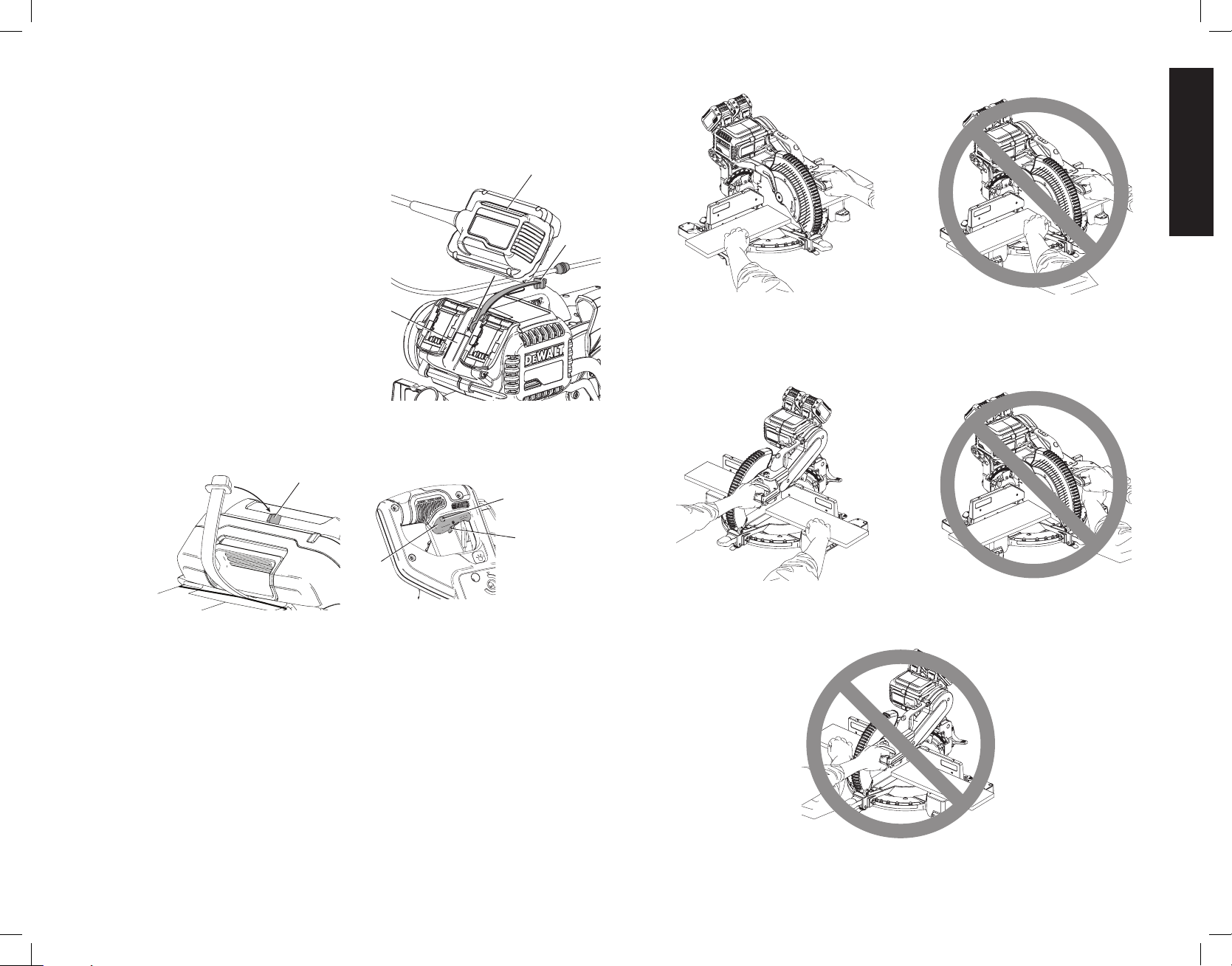
b) Use clamps to support the workpiece whenever possible. If supporting the
workpiece by hand, you must always keep your hand at least 6" (152 mm) from
either side of the saw blade. Do not use this saw to cut pieces that are too small
to be securely clamped or held by hand. If your hand is placed too close to the saw
blade, there is an increased risk of injury from blade contact.
c) The workpiece must be stationary and clamped or held against both the fence
and the table. Do not feed the workpiece into the blade or cut “freehand” in any
way. Unrestrained or moving workpieces could be thrown at high speeds, causing injury.
d) Push the saw through the workpiece. Do not pull the saw through the workpiece.
To make a cut, raise the saw head and pull it out over the workpiece without
cutting, start the motor, press the saw head down and push the saw through the
workpiece. Cutting on the pull stroke is likely to cause the saw blade to climb on top of
the workpiece and violently throw the blade assembly towards the operator.
e) Never cross your hand over the intended line of cutting either in front or behind
the saw blade. Supporting the workpiece “cross handed” i.e. holding the workpiece to
the right of the saw blade with your left hand or vice versa is very dangerous.
f) Do not reach behind the fence with either hand closer than 6" (152 mm) from
either side of the saw blade, to remove wood scraps, or for any other reason
while the blade is spinning. The proximity of the spinning saw blade to your hand may
not be obvious and you may be seriously injured.
g) Inspect your workpiece before cutting. If the workpiece is bowed or warped,
clamp it with the outside bowed face toward the fence. Always make certain that
there is no gap between the workpiece, fence and table along the line of the cut.
Bent or warped workpieces can twist or shift and may cause binding on the spinning saw
blade while cutting. There should be no nails or foreign objects in the workpiece.
h) Do not use the saw until the table is clear of all tools, wood scraps, etc., except
for the workpiece. Small debris or loose pieces of wood or other objects that contact
the revolving blade can be thrown with high speed.
i) Cut only one workpiece at a time. Stacked multiple workpieces cannot be adequately
clamped or braced and may bind on the blade or shift during cutting.
j) Ensure the miter saw is mounted or placed on a level, firm work surface before
use. A level and firm work surface reduces the risk of the miter saw becoming unstable.
k) Plan your work. Every time you change the bevel or miter angle setting, make
sure the fence will not interfere with the blade or the guarding system. Without
turning the tool “ON” and with no workpiece on the table, move the saw blade through
a complete simulated cut to assure there will be no interference or danger of cutting the
fence.
l) Provide adequate support such as table extensions, saw horses, etc. for a
workpiece that is wider or longer than the table top. Workpieces longer or wider than
the miter saw table can tip if not securely supported. If the cut-off piece or workpiece tips,
it can lift the lower guard or be thrown by the spinning blade.
m) Do not use another person as a substitute for a table extension or as additional
support. Unstable support for the workpiece can cause the blade to bind or the workpiece
to shift during the cutting operation pulling you and the helper into the spinning blade.
n) The cut-off piece must not be jammed or pressed by any means against the
spinning saw blade. If confined, i.e. using length stops, the cut-off piece could get
wedged against the blade and thrown violently.
o) Always use a clamp or a fixture designed to properly support round material such
as rods or tubing. Rods have a tendency to roll while being cut, causing the blade to
“bite” and pull the work with your hand into the blade.
p) Let the blade reach full speed before contacting the workpiece. This will reduce the
risk of the workpiece being thrown.
q) If the workpiece or blade becomes jammed, turn the miter saw off. Wait for
all moving parts to stop and disconnect the plug from the power source and/
or remove the battery pack. Then work to free the jammed material. Continued
sawing with a jammed workpiece could cause loss of control or damage to the miter saw.
r) After finishing the cut, release the switch, hold the saw head down and wait for
the blade to stop before removing the cut-off piece. Reaching with your hand near
the coasting blade is dangerous.
s) Hold the handle firmly when making an incomplete cut or when releasing the
switch before the saw head is completely in the down position. The braking action
of the saw may cause the saw head to be suddenly pulled downward, causing a risk of
injury.
Additional Safety Rules for Miter Saws
WARNING: Do not insert the battery into the unit or connect to a power source until
complete instructions are read and understood.
• DO NOT OPERATE THIS MACHINE until it is completely assembled and installed
according to the instructions. A machine incorrectly assembled can cause serious injury.
• OBTAIN ADVICE from your supervisor, instructor, or another qualified person if you are
not thoroughly familiar with the operation of this machine. Knowledge is safety.
• FOLLOW ALL WIRING CODES and recommended electrical connections to prevent
shock or electrocution. Protect electric supply line with at least a 15 ampere time-delay
fuse or a circuit breaker.
• MAKE CERTAIN the blade rotates in the correct direction. The teeth on the blade should
point in the direction of rotation as marked on the saw.
• TIGHTEN ALL CLAMP HANDLES, knobs and levers prior to operation. Loose clamps
can cause parts or the workpiece to be thrown at high speeds.
• BE SURE all blade and blade clamps are clean, recessed sides of blade clamps are
against blade and arbor screw is tightened securely. Loose or improper blade clamping
may result in damage to the saw and possible personal injury.
2
Page 5

English
• ONLY OPERATE WITH DeWALT FLEXVOLT BATTERIES OR WITH THE DeWA LT
CORDED POWER SUPPLY. Only connect the power supply cord to the designated
voltage listed. Overheating, damage to the tool and personal injury may occur.
• DO NOT WEDGE ANYTHING AGAINST THE FAN to hold the motor shaft. Damage to
tool and possible personal injury may occur.
• NEVER CUT FERROUS METALS (those with any iron or steel content) or masonry.
Either of these can cause the carbide tips to fly off the blade at high speeds causing
serious injury.
• DO NOT USE ABRASIVE WHEELS OR BLADES. The excessive heat and abrasive
particles generated by them may damage the saw and cause personal injury.
• NEVER HAVE ANY PART OF YOUR BODY IN LINE WITH THE PATH OF THE SAW
BLADE. Personal injury will occur.
• NEVER APPLY BLADE LUBRICANT TO A RUNNING BLADE. Applying lubricant
could cause your hand to move into the blade resulting in serious injury.
• DO NOT place either hand in the blade area when the saw is connected to the power
source. Inadvertent blade activation may result in serious injury.
• NEVER REACH AROUND OR BEHIND THE SAW BLADE. A blade can cause serious
injury.
• DO NOT REACH UNDERNEATH THE SAW unless it is unplugged and turned off.
Contact with saw blade may cause personal injury.
• SECURE THE MACHINE TO A STABLE SUPPORTING SURFACE. Vibration can
possibly cause the machine to slide, walk, or tip over, causing serious injury.
• USE ONLY CROSSCUT SAW BLADES recommended for miter saws. For best results,
do not use carbide tipped blades with hook angles in excess of 7 degrees. Do not use
blades with deep gullets. These can deflect and contact the guard, and can cause damage
to the machine and/or serious injury.
• USE ONLY BLADES OF THE CORRECT SIZE AND TYPE specified for this tool to
prevent damage to the machine and/or serious injury.
• INSPECT BLADE FOR CRACKS or other damage prior to operation. A cracked or
damaged blade can come apart and pieces can be thrown at high speeds, causing
serious injury. Replace cracked or damaged blades immediately.
• CLEAN THE BLADE AND BLADE CLAMPS prior to operation. Cleaning the blade
and blade clamps allows you to check for any damage to the blade or blade clamps. A
cracked or damaged blade or blade clamp can come apart and pieces can be thrown at
high speeds, causing serious injury.
• DO NOT USE WARPED BLADES. Check to see if the blade runs true and is free from
vibration. A vibrating blade can cause damage to the machine and/or serious injury.
• DO NOT use lubricants or cleaners (particularly spray or aerosol) in the vicinity of the
plastic guard. The polycarbonate material used in the guard is subject to attack by certain
chemicals.
• KEEP GUARD IN PLACE and in working order.
• ALWAYS USE THE KERF PLATE AND REPLACE THIS PLATE WHEN DAMAGED.
Small chip accumulation under the saw may interfere with the saw blade or may cause
instability of workpiece when cutting.
• USE ONLY BLADE CLAMPS SPECIFIED FOR THIS TOOL to prevent damage to the
machine and/or serious injury.
• CLEAN THE MOTOR AIR SLOTS of chips and sawdust. Clogged motor air slots can
cause the machine to overheat, damaging the machine and possibly causing a short which
could cause serious injury.
• NEVER LOCK THE SWITCH IN THE “ON” POSITION. Severe personal injury may
result.
• NEVER STAND ON TOOL. Serious injury could occur if the tool is tipped or if the cutting
tool is unintentionally contacted.
• NEVER LEAVE TOOL RUNNING UNATTENDED. TURN POWER OFF. Don't leave
tool until it comes to a complete stop.
• ADDITIONAL INFORMATION regarding the safe and proper operation of power tools
(i.e., a safety video) is available from the Power Tool Institute, 1300 Sumner Avenue,
Cleveland, OH 44115-2851 (www.powertoolinstitute.com). Information is also available
from the National Safety Council, 1121 Spring Lake Drive, Itasca, IL 60143-3201. Please
refer to the American National Standards Institute ANSI 01.1 Safety Requirements for
Woodworking Machines and the U.S. Department of Labor OSHA 1910.213 Regulations.
WARNING: Cutting plastics, sap coated wood, and other materials may cause melted
material to accumulate on the blade tips and the body of the saw blade, increasing the risk of
blade overheating and binding while cutting.
WARNING: Always wear proper personal hearing protection that conforms to ANSI
S12.6 (S3.19) during use. Under some conditions and duration of use, noise from this
product may contribute to hearing loss.
WARNING: ALWAYS use safety glasses. Everyday eyeglasses are NOT safety glasses.
Also use face or dust mask if cutting operation is dusty. ALWAYS WEAR CERTIFIED SAFETY
EQUIPMENT:
• ANSI Z87.1 eye protection (CAN/CSA Z94.3),
• ANSI S12.6 (S3.19) hearing protection,
• NIOSH/OSHA/MSHA respiratory protection.
WARNING: Some dust created by power sanding, sawing, grinding, drilling, and other
construction activities contains chemicals known to the State of California to cause cancer,
birth defects or other reproductive harm. Some examples of these chemicals are:
• lead from lead-based paints,
• crystalline silica from bricks and cement and other masonry products, and
• arsenic and chromium from chemically-treated lumber.
Your risk from these exposures varies, depending on how often you do this type of work.
To reduce your exposure to these chemicals: work in a well ventilated area, and work with
approved safety equipment, such as those dust masks that are specially designed to filter out
microscopic particles.
• Avoid prolonged contact with dust from power sanding, sawing, grinding, drilling,
and other construction activities. Wear protective clothing and wash exposed
areas with soap and water. Allowing dust to get into your mouth, eyes, or lay on the skin
may promote absorption of harmful chemicals.
WARNING: Use of this tool can generate and/or disperse dust, which may cause serious
and permanent respiratory or other injury. Always use NIOSH/OSHA approved respiratory
protection appropriate for the dust exposure. Direct particles away from face and body.
• The label on your tool may include the following symbols. The symbols and their definitions
are as follows:
V ...................... volts A ......................... amperes
Hz.................... hertz W ........................ watts
min .................. minutes or AC ............. alternating current
or DC ..... direct current or AC/DC ..... alternating or direct
.................... Class I Construction (grounded) current
................... Class II Construction
(double insulated) n ......................... rated speed
…/min ............. per minute ........................ earthing terminal
BPM ................ beats per minute ........................ safety alert symbol
IPM ................. impacts per minute SPM ..................strokes per minute
RPM ................ revolutions per minute sfpm ................... surface feet per minute
.................... visible radiation ....................... wear eye protection
.................... wear respiratory protection ....................... wear hearing protection
n
o ....................... no load speed
3
Page 6
English
For your convenience and safety, the following warning labels are on your miter saw.
ON MOTOR HOUSING:
WARNING: TO REDUCE THE RISK OF INJURY, USER MUST READ
INSTRUCTION MANUAL BEFORE OPERATING MITER SAW.
WHEN SERVICING, USE ONLY IDENTICAL RE PLACE MENT PARTS.
DO NOT EXPOSE TO RAIN OR USE IN DAMP LOCATIONS.
ALWAYS USE PROPER EYE AND RESPIRATORY PROTECTION.
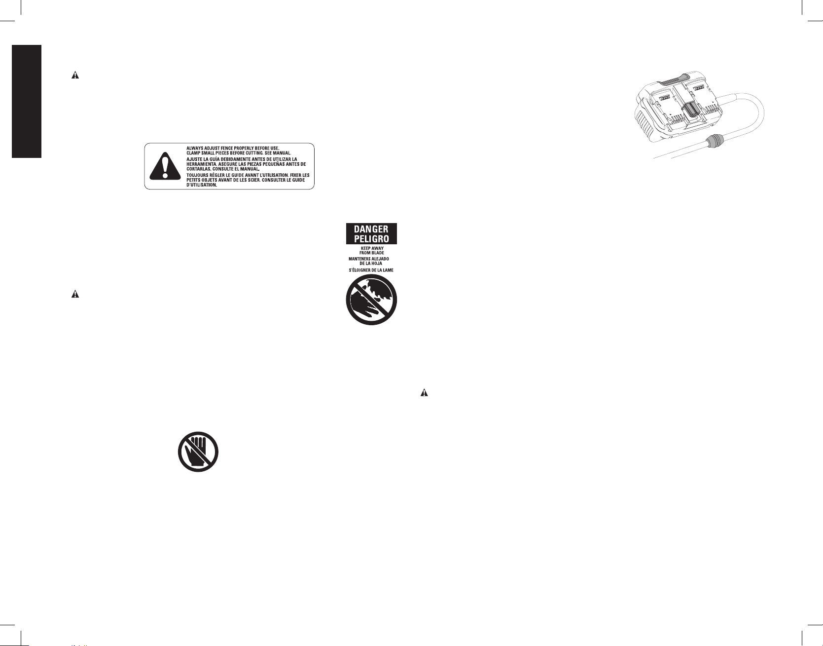
ON MOVING FENCES:
ALWAYS ADJUST FENCE PROPERLY BEFORE USE. CLAMP SMALL PIECES
BEFORE CUTTING. SEE MANUAL.
ON GUARD:
DANGER–KEEP AWAY FROM BLADE.
ON UPPER GUARD:
PROPERLY SECURE BRACKET WITH BOTH SCREWS BEFORE
USE.
ON TABLE: (2 PLACES)
WARNING: TO REDUCE THE RISK OF INJURY, USER MUST
READ INSTRUCTION MANUAL BEFORE OPERATING MITER
SAW. KEEP HANDS OUT OF PATH OF SAW BLADE. DO
NOT OPERATE SAW WITHOUT GUARDS IN PLACE. CHECK
LOWER GUARD FOR PROPER CLOSING BEFORE EACH USE.
ALWAYS TIGHTEN ADJUSTMENT KNOBS BEFORE USE. DO NOT PERFORM
ANY OPERATION FREEHAND. CLAMP SMALL PIECES BEFORE CUTTING.
NEVER REACH IN BACK OF SAW BLADE. NEVER CROSS ARMS IN FRONT
OF BLADE. TURN OFF TOOL AND WAIT FOR SAW BLADE TO STOP BEFORE
MOVING WORKPIECE, CHANGING SETTINGS OR MOVING HANDS. REMOVE
BATTERY PACK BEFORE ADJUSTING, CHANGING BLADE OR SERVICING.
TO REDUCE THE RISK OF INJURY, RETURN CARRIAGE TO THE FULL REAR
POSITION AFTER EACH CROSSCUT OPERATION. THINK! YOU CAN PREVENT
ACCIDENTS.
ON BASE: (2 PLACES)
Electrical Connection
Be sure your power source agrees with the nameplate marking. 120 volts, AC means that
your saw will operate on alternating current. Do not operate with DC power. A voltage
decrease of 10 percent or more will cause a loss of power and overheating. All DeWALT tools
are factory tested. If this tool does not operate, check the power supply.
This miter saw operates on either two 60V battery packs or by using the DeWALT corded
power supply.
Using the Corded Power Supply
The DeWALT corded power supply is designed to
provide power for DeWALT 120V Max* FLEXVOLT
cordless tools. Insert the corded power supply into the
miter saw battery slot (refer to Installing and
Removing the Corded Power Supply into and
from Tool) and plug the power supply into an AC
outlet. The power supply will act as the power source
to the tool. Your DeWALT corded power supply should
only be used with standard household 120 VAC, 60
Hz power or a 120VAC 60Hz generator.
The corded power supply is suitable for use with both
grounded and double insulated 120V AC tools. When the power supply is utilized with a
grounded tool, the tool inlet will be equipped with a ground prong that allows the ground path
from the tool to connect to the power supply. When the power supply is used with this double
insulated miter saw, no ground connection is made from the tool to the power supply as no
ground connection is required.
TM
Fig. 1
Additional Specific Usage Instructions
The corded power supply may become warm to the touch during use. This is a normal
condition and does not indicate a problem.
IMPORTANT. The power supply is not user serviceable. There are no user serviceable parts
inside the power supply.
Servicing at an authorized service center is required to avoid damage to static sensitive
internal components.
Batteries and Chargers
The battery pack is not fully charged out of the carton. Before using the battery pack and
charger, read the safety instructions below and then follow charging procedures outlined.
When ordering replacement battery packs, be sure to include the catalog number andvoltage.
Your tool uses a DeWALT charger. Be sure to read all safety instructions before using
your charger. Consult the chart at the end of this manual for compatibility of chargers and
batterypacks.
Important Safety Instructions for All Battery Packs
WARNING: Read all safety warnings and all instructions for the battery pack, charger and
power tool. Failure to follow the warnings and instructions may result in electric shock, fire
and/or serious injury.
• Do not charge or use the battery pack in explosive atmospheres, such as
in the presence of flammable liquids, gases or dust. Inserting or removing the
battery pack from the charger may ignite the dust orfumes.
• Never force the battery pack into the charger. Do not modify the battery pack
in any way to fit into a non-compatible charger as battery pack may rupture
causing serious personal injury. Consult the chart at the end of this manual for
compatibility of batteries andchargers.
• Charge the battery packs only in designated DeWALTchargers.
• DO NOT splash or immerse in water or otherliquids.
• Do not store or use the tool and battery pack in locations where the
temperature may reach or exceed 104°F (40 °C) (such as outside sheds or
metal buildings in summer). For best life store battery packs in a cool, drylocation.
NOTE: Do not store the battery packs in a tool with the trigger switch locked
on. Never tape the trigger switch in the ONposition.
4
Page 7
English
• Do not incinerate the battery pack even if it is severely damaged or is
completely worn out. The battery pack can explode in a fire. Toxic fumes and
materials are created when lithium ion battery packs areburned.
• If battery contents come into contact with the skin, immediately wash area
with mild soap and water. If battery liquid gets into the eye, rinse water over the open
eye for 15 minutes or until irritation ceases. If medical attention is needed, the battery
electrolyte is composed of a mixture of liquid organic carbonates and lithiumsalts.
• Contents of opened battery cells may cause respiratory irritation. Provide fresh
air. If symptoms persist, seek medicalattention.
WARNING: Burn hazard. Battery liquid may be flammable if exposed to spark orflame.
WARNING: Fire hazard. Never attempt to open the battery pack for any reason. If the
battery pack case is cracked or damaged, do not insert into the charger. Do not crush, drop
or damage the battery pack. Do not use a battery pack or charger that has received a sharp
blow, been dropped, run over or damaged in any way (e.g., pierced with a nail, hit with a
hammer, stepped on). Damaged battery packs should be returned to the service center
forrecycling.
TRANSPORTATION
WARNING: Fire hazard. Do not store or carry the battery pack so that metal
objects can contact exposed battery terminals. For example, do not place the battery
pack in aprons, pockets, tool boxes, product kit boxes, drawers, etc., with loose nails, screws,
keys, etc. Transporting batteries can possibly cause fires if the battery terminals
inadvertently come in contact with conductive materials such as keys, coins, hand
tools and the like. The US Department of Transportation Hazardous Material Regulations
(HMR) actually prohibit transporting batteries in commerce or on airplanes in carry-on
baggage UNLESS they are properly protected from short circuits. So when transporting
individual battery packs, make sure that the battery terminals are protected and well insulated
from materials that could contact them and cause a short circuit.
SHIPPING THE DEWALT FLEXVOLT™ BATTERY
The DeWALT FLEXVOLT™ battery has two modes: Use and Shipping.
Use Mode: When the FLEXVOLT™ battery stands alone or is in a DeWALT 20V Max*
product, it will operate as a 20V Max* battery. When the FLEXVOLT™ battery is in a 60V Max*
or a 120V Max* (two 60V Max* batteries) product, it will operate as a 60V Max* battery.
Shipping Mode: When the cap is attached to the FLEXVOLT™
battery, the battery is in Shipping Mode. Strings of cells are
electrically disconnected within the pack resulting in three batteries
with a lower Watt hour (Wh) rating as compared to one battery with
a higher Watt hour rating. This increased quantity of three batteries
with the lower Watt hour rating can exempt the pack from certain shipping regulations that
are imposed upon the higher Watt hour batteries.
The battery label indicates two Watt hour ratings (see example). Depending on how the
battery is shipped, the appropriate Watt hour rating must be used to determine the applicable
shipping requirements. If utilizing the shipping cap, the pack will be considered 3 batteries at
the Watt hour rating indicated for “Shipping”. If shipping without the cap or in a tool, the pack
will be considered one battery at the Watt hour rating indicated next to “Use”.
Example of Use and Shipping Label Marking
USE: 120 Wh Shipping: 3 x 40 Wh
Transport Watt hour rating indicates 3 x 40 Wh, meaning 3 batteries of 40 Watt hours each.
The Use Watt hour rating indicates 120 Watt hour (1 battery implied).
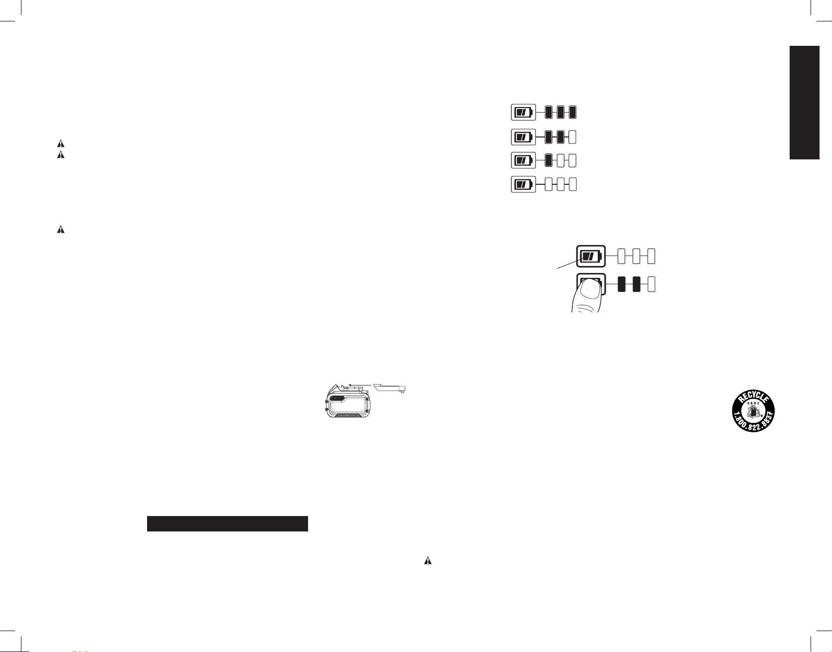
FUEL GAUGE BATTERY PACKS (FIG. 2)
Some DeWALT battery packs include a fuel gauge which consists of three green LED lights
that indicate the level of charge remaining in the batterypack.
The fuel gauge is an indication of approximate levels of charge remaining in the battery pack
according to the followingindicators:
75–100% charged
51–74% charged
< 50% charged
Pack needs to be charged
To actuate the fuel gauge, press and hold the fuel gauge button (AL). A combination of the
three green LED lights will illuminate designating the level of charge left. When the level of
charge in the battery is below the usable limit, the fuel gauge will not illuminate and the battery
will need to berecharged.
Fig. 2
AL
NOTE: The fuel gauge is only an indication of the charge left on the battery pack. It does
not indicate tool functionality and is subject to variation based on product components,
temperature and end-userapplication.
For more information regarding fuel gauge battery packs, please contact call 1-800-4-DeWA LT
(1-800-433-9258) or visit our website www.dewalt.com.
The RBRC® Seal
The RBRC® (Rechargeable Battery Recycling Corporation) Seal on the nickel
cadmium, nickel metal hydride or lithium-ion batteries (or battery packs)
indicates that the costs to recycle these batteries (or battery packs) at the end
of their useful life have already been paid by DeWALT. In some areas, it is illegal
to place spent nickel cadmium, nickel metal hydride or lithium-ion batteries
in the trash or municipal solid waste stream and the Call2Recycle® program provides an
environmentally consciousalternative.
Call 2 Recycle, Inc., in cooperation with DeWALT and other battery users, has established the
program in the United States and Canada to facilitate the collection of spent nickel cadmium,
nickel metal hydride or lithium-ion batteries. Help protect our environment and conserve
natural resources by returning the spent nickel cadmium, nickel metal hydride or lithium-ion
batteries to an authorized DeWALT service center or to your local retailer for recycling. You
may also contact your local recycling center for information on where to drop off the spent
battery. RBRC® is a registered trademark of Call 2 Recycle,Inc.
RBRC™ is a registered trademark of the Rechargeable Battery RecyclingCorporation.
Important Safety Instructions for All Battery Chargers
WARNING: Read all safety warnings and all instructions for the battery pack,
charger and power tool. Failure to follow the warnings and instructions may result
in electric shock, fire and/or serious injury.
5
Page 8
English
• DO NOT attempt to charge the battery pack with any chargers other than
• These chargers are not intended for any uses other than charging DeWA LT
• Do not expose the charger to rain orsnow.
• Pull by the plug rather than the cord when disconnecting the charger. This will
• Make sure that the cord is located so that it will not be stepped on, tripped
• Do not use an extension cord unless it is absolutely necessary. Use of improper
• When operating a charger outdoors, always provide a dry location and use an
• An extension cord must have adequate wire size (AWG or American Wire
• Do not place any object on top of the charger or place the charger on a soft
• Do not operate the charger with a damaged cord orplug.
• Do not operate the charger if it has received a sharp blow, been dropped or
• Do not disassemble the charger; take it to an authorized service center when
• Disconnect the charger from the outlet before attempting any cleaning. This
• NEVER attempt to connect 2 chargerstogether.
• The charger is designed to operate on standard 120V household electrical
the ones in this manual. The charger and battery pack are specifically designed to
worktogether.
rechargeable batteries. Any other uses may result in risk of fire, electric shock
orelectrocution.
reduce the risk of damage to the electric plug andcord.
over or otherwise subjected to damage orstress.
extension cord could result in risk of fire, electric shock orelectrocution.
extension cord suitable for outdoor use. Use of a cord suitable for outdoor use
reduces the risk of electricshock.
Gauge) for safety. The smaller the gauge number of the wire, the greater the capacity
of the cable, that is, 16 gauge has more capacity than 18 gauge. An undersized cord
will cause a drop in line voltage resulting in loss of power and overheating. When using
more than one extension to make up the total length, be sure each individual extension
contains at least the minimum wire size. The following table shows the correct size to
use depending on cord length and nameplate ampere rating. If in doubt, use the next
heavier gauge. The lower the gauge number, the heavier thecord.
Minimum Gauge for Cord Sets
Volts Total Length of Cord in Feet (meters)
Ampere Rating
More
Than
surface that might block the ventilation slots and result in excessive internal
heat. Place the charger in a position away from any heat source. The charger is
ventilated through slots in the top and the bottom of thehousing.
otherwise damaged in any way. Take it to an authorized servicecenter.
service or repair is required. Incorrect reassembly may result in a risk of electric
shock, electrocution orfire.
will reduce the risk of electric shock. Removing the battery pack will not reduce
thisrisk.
power. Do not attempt to use it on any other voltage. This does not apply to the
vehicularcharger.
Not More
Than
0 6 18 16 16 14
6 10 18 16 14 12
10 12 16 16 14 12
12 16 14 12 Not Recommended
120V 25 (7.6) 50 (15.2) 100 (30.5) 150 (45.7)
240V 50 (15.2) 100 (30.5) 200 (61.0) 300 (91.4)
AWG
WARNING: Shock hazard. Do not allow any liquid to get inside the charger. Electric shock
mayresult.
WARNING: Burn hazard. Do not submerge the battery pack in any liquid or allow any
liquid to enter the battery pack. Never attempt to open the battery pack for any reason. If the
plastic housing of the battery pack breaks or cracks, return to a service center for recycling.
CAUTION: Burn hazard. To reduce the risk of injury, charge only DeWALT rechargeable
battery packs. Other types of batteries may overheat and burst resulting in personal injury and
propertydamage.
NOTICE: Under certain conditions, with the charger plugged into the power supply, the
charger can be shorted by foreign material. Foreign materials of a conductive nature, such
as, but not limited to, grinding dust, metal chips, steel wool, aluminum foil or any buildup of
metallic particles should be kept away from the charger cavities. Always unplug the charger
from the power supply when there is no battery pack in the cavity. Unplug the charger before
attempting toclean.
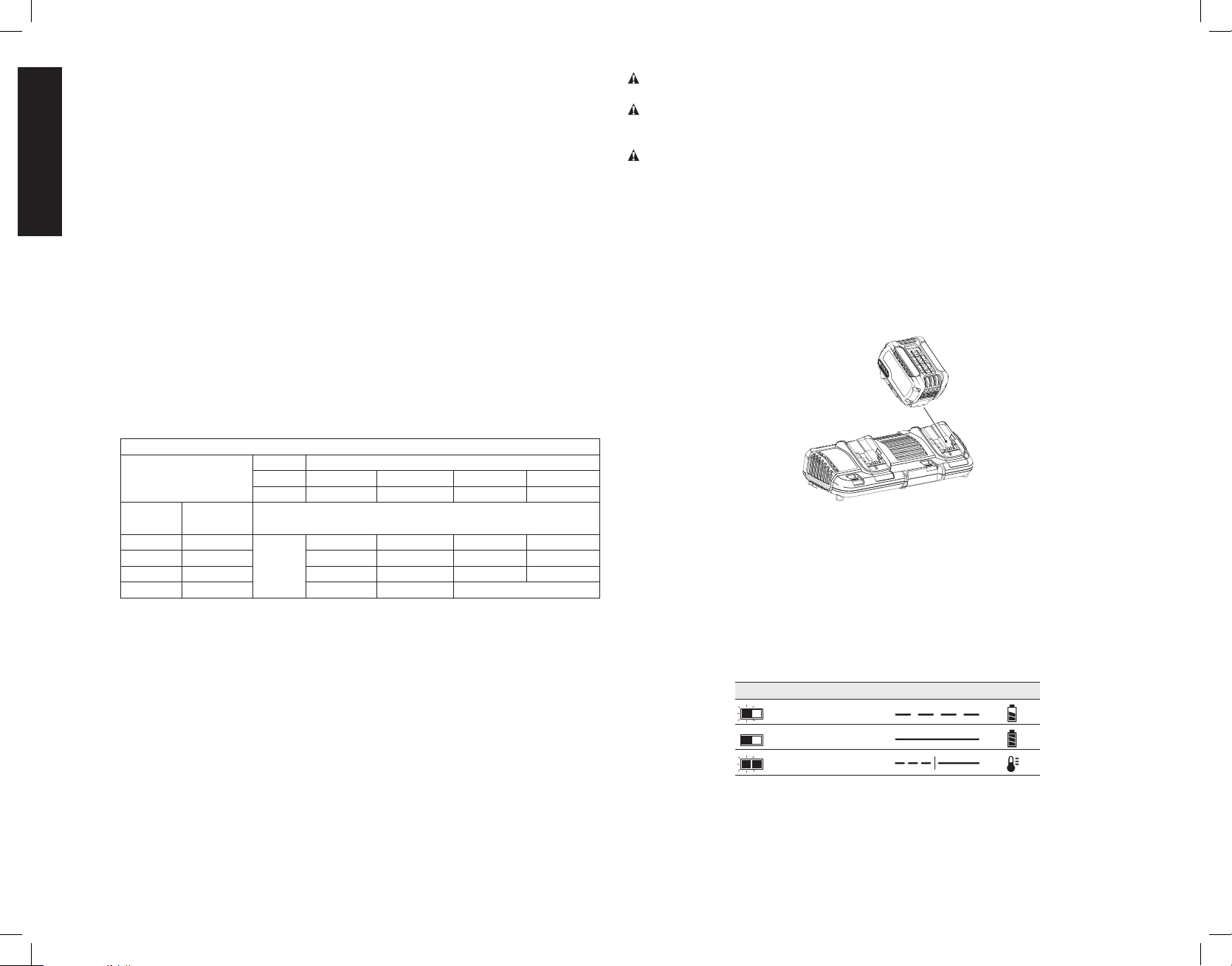
Charging a Battery (Fig. 3)
1. Plug the charger into an appropriate outlet before inserting battery pack.
FIG. 3
1. Insert the battery pack into the charger, making sure the battery pack is fully seated in the
charger. The red (charging) light will blink continuously indicating that the charging process
has started.
2. The completion of charge will be indicated by the red light remaining ON continuously. The
battery pack is fully charged and may be used at this time or left in the charger. To remove
the battery pack from the charger, push the battery release button on the battery pack.
NOTE: To ensure maximum performance and life of lithium-ion battery packs, charge the
battery pack fully before first use.
CHARGER OPERATION
Refer to the indicators below for the charge status of the battery pack.
DCB107, DCB112, DCB113, DCB115, DCB118, DCB132
Charging
Fully Charged
Hot/Cold Pack Delay*
* The red light will continue to blink, but a yellow indicator light will be illuminated during this
operation. Once the battery pack has reached an appropriate temperature, the yellow light
will turn off and the charger will resume the charging procedure.
The compatible charger(s) will not charge a faulty battery pack. The charger will indicate faulty
battery pack by refusing to light or by displaying a problem pack or charger blink pattern.
6
Page 9

English
NOTE: This could also mean a problem with a charger.
If the charger indicates a problem, take the charger and battery pack to be tested at an
authorized service center.
HOT/COLD PACK DELAY
When the charger detects a battery pack that is too hot or too cold, it automatically starts a
Hot/Cold Pack Delay, suspending charging until the battery pack has reached an appropriate
temperature. The charger then automatically switches to the pack charging mode. This
feature ensures maximum battery pack life.
A cold battery pack will charge at a slower rate than a warm battery pack. The battery pack
will charge at that slower rate throughout the entire charging cycle and will not return to
maximum charge rate even if the battery pack warms.
The DCB118 charger is equipped with an internal fan designed to cool the battery pack. The
fan will turn on automatically when the battery pack needs to be cooled.
Never operate the charger if the fan does not operate properly or if ventilation slots are
blocked. Do not permit foreign objects to enter the interior of the charger.
ELECTRONIC PROTECTION SYSTEM
Li-Ion tools are designed with an Electronic Protection System that will protect the battery
pack against overloading, overheating or deep discharge.
The tool will automatically turn off if the Electronic Protection System engages. If this occurs,
place the lithium-ion battery pack on the charger until it is fully charged.
Wall Mounting
These chargers are designed to be wall mountable or to sit upright on a table or work surface.
If wall mounting, locate the charger within reach of an electrical outlet, and away from a corner
or other obstructions which may impede air flow. Use the back of the charger as a template
for the location of the mounting screws on the wall. Mount the charger securely using drywall
screws (purchased separately) at least 1" (25.4 mm) long, with a screw head diameter of
0.28–0.35" (7–9mm), screwed into wood to an optimal depth leaving approximately 7/32"
(5.5 mm) of the screw exposed. Align the slots on the back of the charger with the exposed
screws and fully engage them in the slots.
Charger Cleaning Instructions
WARNING: Shock hazard. Disconnect the charger from the AC outlet before cleaning.
Dirt and grease may be removed from the exterior of the charger using a cloth or soft nonmetallic brush. Do not use water or any cleaning solutions.
Important Charging Notes
1. Longest life and best performance can be obtained if the battery pack is charged when
the air temperature is between 65°F and 75°F (18° – 24°C). DO NOT charge the battery
pack in an air temperature below +40°F (+4.5°C), or above +104°F (+40°C). This is
important and will prevent serious damage to the battery pack.
2. The charger and battery pack may become warm to the touch while charging. This is a
normal condition, and does not indicate a problem. To facilitate the cooling of the battery
pack after use, avoid placing the charger or battery pack in a warm environment such as
in a metal shed or an uninsulated trailer.
3. If the battery pack does not charge properly:
a. Check operation of receptacle by plugging in a lamp or other appliance;
b. Check to see if receptacle is connected to a light switch which turns power off when
you turn out the lights;
c. Move the charger and battery pack to a location where the surrounding air temperature
is approximately 65°F – 75°F (18° – 24°C);
d. If charging problems persist, take the tool, battery pack and charger to your local service
center.
4. The battery pack should be recharged when it fails to produce sufficient power on jobs
which were easily done previously. DO NOT CONTINUE to use under these conditions.
Follow the charging procedure. You may also charge a partially used pack whenever you
desire with no adverse effect on the battery pack.
5. Foreign materials of a conductive nature such as, but not limited to, grinding dust, metal
chips, steel wool, aluminum foil, or any buildup of metallic particles should be kept away
from charger cavities. Always unplug the charger from the power supply when there is no
battery pack in the cavity. Unplug the charger before attempting to clean.
6. Do not freeze or immerse the charger in water or any other liquid.
Storage Recommendations
1. The best storage place is one that is cool and dry, away from direct sunlight and excess
heat or cold.
2. For long storage, it is recommended to store a fully charged battery pack in a cool dry
place out of the charger for optimal results.
NOTE: Battery packs should not be stored completely depleted of charge. The battery pack
will need to be recharged before use.
SAVE THESE INSTRUCTIONS FOR FUTURE USE
UNPACKING YOUR SAW
Check the contents of your miter saw carton to make sure that you have received all parts.
In addition to this instruction manual, the carton should contain:
1 DHS716 miter saw
1 DeWA LT 12" (305 mm) dia. saw blade
May include:
1 DeWALT corded power supply
2 60V batteries
1 Dual port charger
In bag:
1 Blade wrench
1 Dustbag
1 Instruction manual
Specifications
CAPACITY OF CUT
50º miter left and right
48º bevel left and right
ANGLE MAXIMUM CAPACITY OF CUT RESULT
0° miter
45° miter
45º bevel – left
45º bevel – right
Height 3.6" (91.5 mm) Width 7.2" (183 mm)
Width 7.9:" (200.7 mm) Height 2.9" (73.7mm)
Height 3.6" (91.5 mm) Width 4.9" (125 mm)
Width 5.5” (140 mm) Height 2.9" (73.7 mm)
Height 2.3" (58.4 mm) Width 7.4" (188 mm)
Width 7.9" (200.7 mm) Height 1.9" (48.3 mm)
Height 7.9" (200.7 mm) Width 1.1" (28 mm)
Width 1.6" (40.6 mm) Height 7.1" (180.3 mm)
7
Page 10
English
FIG. 4
D
A
B
Q
P
O
N
E
J
S
C
R
T
U
Y
V
M
E
L
H
F
G
I
K
Your saw is capable of cutting baseboard moldings 0.9" (22.9 mm) thick by 6" (152mm) tall
on a 45º right or left miter.
NOTE: Your saw is capable of cutting the following once a special set-up procedure is
followed (see Special Cuts).
0° miter Height 1.5" (38 mm) Width 10" (255 mm)
45º miter Height 1.5" (38 mm) Width 7.5" (190.5 mm)
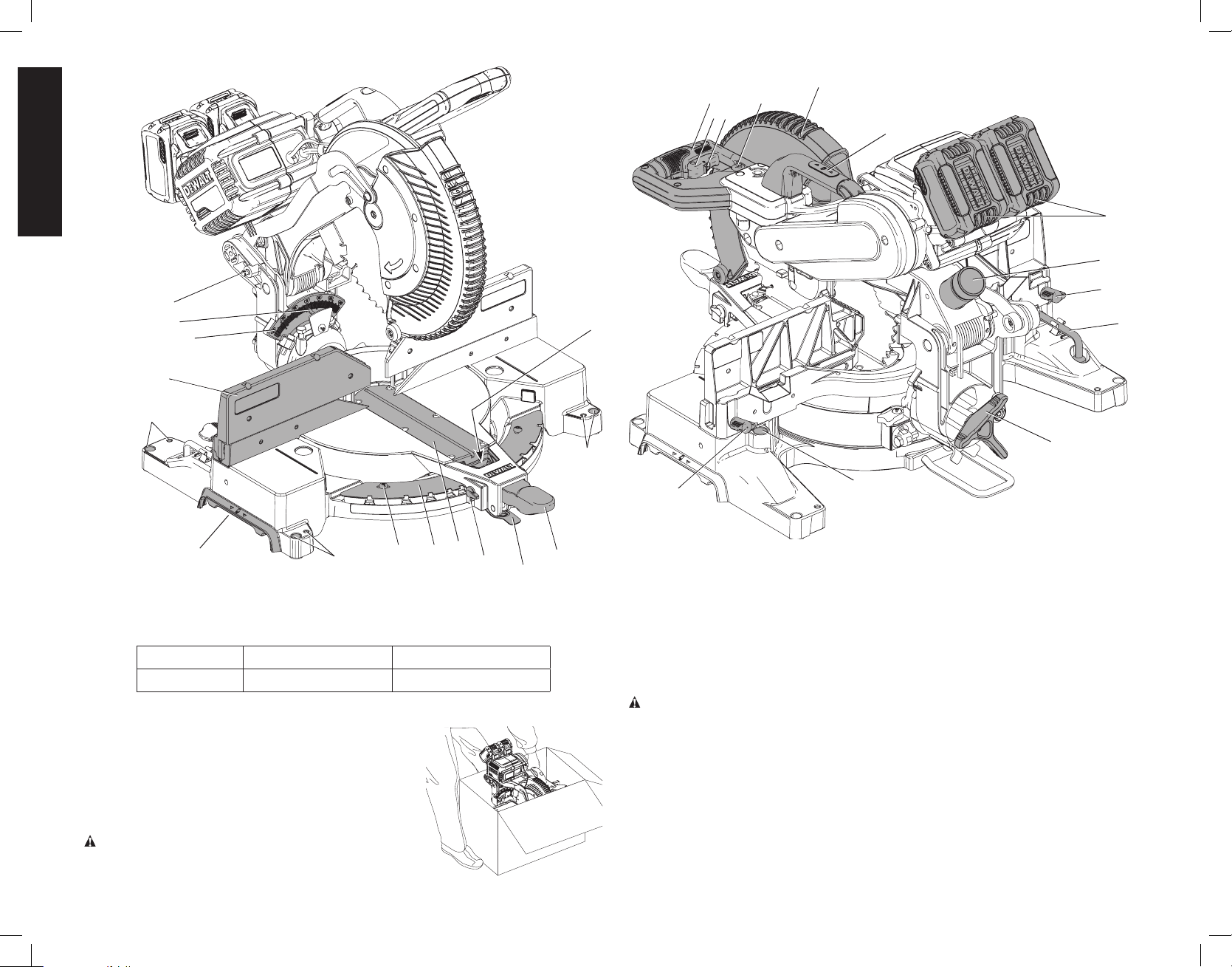
Familiarization
FIG. 5
Your miter saw is fully assembled in the car ton. Open the box
and lift the saw out by the convenient lifting handle, as
shown in Figure 5. Place the saw on a smooth, flat surface
such as a workbench, strong table or DeWALT miter saw
stand. Examine Figure 4 to become familiar with the saw
and its various parts. The section on adjustments will refer
to these terms and you must know what and where the
parts are.
CAUTION: Pinch Hazard. To reduce the risk of injury,
keep thumb underneath the operating handle (A) when
E
Y
X
W
pulling the handle down. The lower guard will move up as the handle is pulled down which
could cause pinching. The handle is placed close to the guard for special cuts.
Press down lightly on the operating handle and pull out the lock down pin (Q, Fig. 4). Gently
release the downward pressure and hold the arm allowing it to rise to its full height. Use the
lock down pin when carrying the saw from one place to another. Always use the lifting handle
to transport the saw or the hand indentations (M, Fig. 4).
COMPONENTS (Fig. 4)
WARNING: Never modify the power tool or any part of it. Damage or personal injury could
result.
A. Operating handle
B. Trigger switch
C. Trigger lock-off switch
D. Lower guard
E. Mounting holes
F. Miter lock lever
G. Miter release lever
H. Miter detent override
lever
I. Kerf plate
J. Miter scale pointer
K. Miter scale
L. Miter scale screws
M. Hand indentations
N. Fence
O. Bevel scale
P. Bevel scale pointer
Q. Lock down pin
R. Lifting handle
S. CUTLINE™ worklight
switch
T. Battery packs
U. Dust port
V. Hex wrench
W. Bevel lock knob
X. Clamp hole
Y. Fence adjustment knob
8
Page 11
English
INTENDED USE
This miter saw is intended for use by construction professionals for cutting lumber, trim
molding and shapes, and other soft materials.
DO NOT use under wet conditions or in presence of flammable liquids or gases.
This miter saw is a professional power tool. DO NOT let children come into contact with the
tool. Supervision is required when inexperienced operators use this tool.
Transporting and Storing the Saw (Fig. 4)
WARNING: To reduce the risk of serious personal injury, turn tool off and remove
the battery packs or power supply before transporting, making any adjustments,
cleaning, repairing, or removing/installing attachments or accessories. An accidental
start-up can cause injury.
WARNING: To reduce the risk of serious personal injury, ALWAYS lock the miter
lock lever (F), bevel lock knob (W), lock down pin (Q) and fence adjustment knobs (Y) before
transporting saw.
In order to conveniently carry the miter saw from place to place, a lifting handle (R) has been
included on the top of the saw arm and hand indentations (M) in the base, as shown in Figure 4.
HEAD LOCK DOWN PIN (FIG. 4)
WARNING: The lock down pin should be used ONLY when carrying or storing the
saw. NEVER use the lock down pin for any cutting operation.
To lock the saw head in the down position, push the head down, push the lock down pin (Q)
in and release the saw head. This will hold the saw head safely down for moving the saw from
place to place. To release, press the saw head down and pull the pin out.
FEATURES AND CONTROLS
WARNING: To reduce the risk of serious personal injury, turn tool off and remove
the battery packs or power supply before transporting, making any adjustments,
cleaning, repairing, or removing/installing attachments or accessories. An accidental
start-up can cause injury.
USE OF CUTLINE™ LED WORKLIGHT (FIG. 4)
CAUTION: Do not stare into worklight. Serious eye injury could result.
The CUTLINE™ LED worklight can be turned on by the CUTLINE™ worklight switch (S).
The light will automatically turn off within 20 seconds if the saw is not in use. The light is also
activated automatically every time the tool's main trigger (B) is pulled.
To cut through an existing pencil line on a piece of wood, turn on the CUTLINE™ worklight
using the CUTLINE™ worklight switch (S) (not with the main trigger), then pull down on the
operating handle (A) to bring the saw blade close to the wood. The shadow of the blade will
appear on the wood. This shadow line represents the material that the blade will remove
when performing a cut. To correctly locate your cut to the pencil line, align the pencil line with
the edge of the blade’s shadow. Keep in mind that you may have to adjust the miter or bevel
angles in order to match the pencil line exactly.
Your saw is equipped with a battery monitoring feature. The CUTLINE™ worklight begins
to flash when the battery is near the end of its useful charge and/or when the battery is too
hot. Charge the battery prior to continuing cutting applications. Refer to Charging a Battery
under Important Safety Instructions for All Battery Chargers for battery charging
instructions.
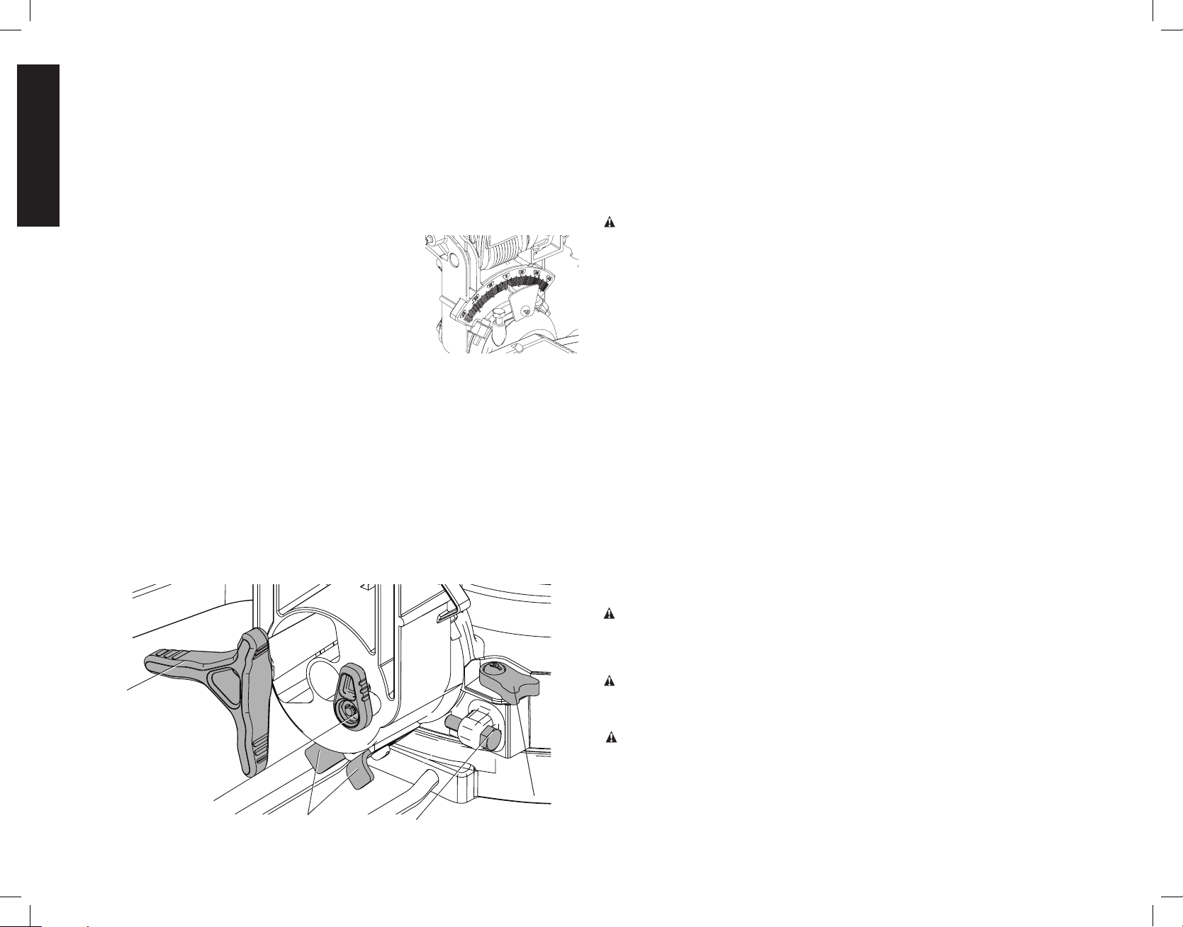
MITER CONTROL (FIG. 4, 6)
The miter lock lever (F) and miter release lever (G)
allow you to miter your saw 50° left and right. To
miter the saw, unlock the miter lock lever (F) by
pulling upward, squeeze the miter release lever (G)
and set the miter angle desired on the miter scale.
Lock miter lock lever (F) by pressing downward.
To override the detents, unlock the miter lock lever
(F) by pulling upward. Pull up on the miter release
lever (G) then push the miter detent override
lever (H) upward. Set the miter angle desired on
the miter scale. Lock the miter lock lever (F) be
pressing downward.
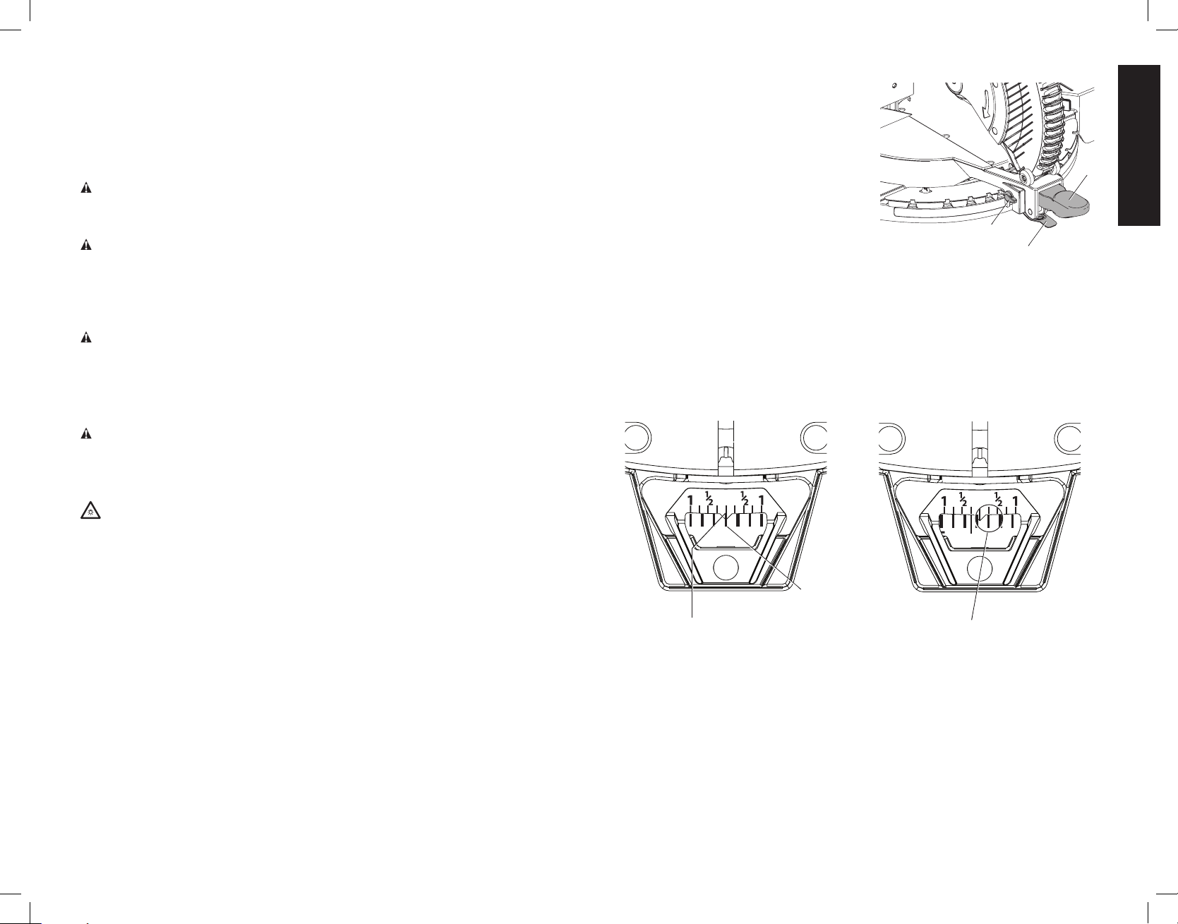
VERNIER SCALE (FIG. 7, 8)
Your saw is equipped with a vernier scale for added precision. The vernier scale allows you
to accurately set miter angles to the nearest 1/4°. To use the vernier scale follow the steps
listed below.
(As an example, let’s assume that the angle you want to miter is 9-1/4° right).
1. Turn off miter saw.
2. Set the miter angle to the nearest whole degree desired by aligning the center mark in the
vernier scale, shown in Figure 7, with the whole degree number etched in the miter scale.
Examine Figure 7 closely; the setting shown is 9° right miter.
FIG. 7
10
MITER
ANGLE
CENTER MARK ON VERNIER SCALE
ALIGNS WITH DESIRED WHOLE ANGLE
ON MITER SCALE (9° RIGHT MITER)
3. To set the additional 1/4°, squeeze the miter arm lock and carefully move the arm to the
RIGHT until the 1/4° vernier mark aligns with the CLOSEST degree mark on the miter
scale. In our example, the closest degree mark on the miter scale happens to be 10°.
Figure 8 shows a setting of 9-1/4° right miter.
For settings that require partial degrees (1/4, 1/2, 3/4°) align the desired vernier mark with
the CLOSEST degree mark on the miter scale, as described below (The plastic vernier plate
is inscribed with marks for 1/4, 1/2, 3/4 and 1°. Only the 1/2° and the 1° are numerically
labeled.)
FIG. 6
F
H
G
FIG. 8
10
1/4° VERNIER MARK ALIGNS WITH
CLOSEST WHOLE DEGREE MARK ON
MITER SCALE (9-1/4° RIGHT MITER)
9
Page 12
English
WHEN MITERING TO THE RIGHT
To increase the miter angle when mitering to the right, move the arm to align the appropriate
vernier mark with the closest mark on the miter scale to the right. To decrease the miter angle
when mitering to the right, move the arm to align the appropriate vernier mark with the closest
mark on the miter scale to the left.
WHEN MITERING TO THE LEFT
To increase the miter angle when mitering to the left, move the arm to align the appropriate
vernier mark with the closest mark on the miter scale to the left. To decrease the miter angle
when mitering to the left, move the arm to align the appropriate vernier mark with the closest
mark on the miter scale to the right.
BEVEL LOCK (FIG. 9, 10)
The bevel lock knob (W, Fig. 10) allows you to bevel the saw
48º left or right. To loosen the handle and adjust the bevel
setting, turn the handle counter clock wise, the saw head
bevels easily to the left or to the right once the 0º bevel stop
override knob (AG, Fig. 10) is pulled. To tighten, turn the
handle clockwise. Bevel degree markings are on the bevel
scale at bottom front of the saw arm (Fig.9).
0º BEVEL OVERRIDE (FIG. 10)
The 0º bevel stop override knob (AG) allows you to bevel the
saw to the right past the 0º mark.
The saw will automatically stop at 0º when brought up from the left. To move past 0º to the
right, pull the 0º bevel stop override knob (AG). The bevel stop override knob can be locked
out by pulling the knob out and rotating it 180º.
45º BEVEL STOP OVERRIDES (FIG. 10)
The 45º bevel override levers (AI) are held secure with their attachment screw to prevent
inadvertent movement. Use the bit on the blade wrench to loosen the attachment screw. This
allows the override levers (AI) to be pulled outward and the saw head to pivot past the 45º
mark. Be sure to retighten the attachment screw when finished.
33.9º BEVEL STOPS (FIG. 10)
The two stop pawls (AH) (one on either side of the saw) are used to stop the saw head bevel
setting at 33.9º. This setting is used primarily for cutting crown moldings laid flat on the table.
FIG. 10
W
AG
AI
FIG. 9
AJ
AH
AUTOMATIC ELECTRIC BLADE BRAKE
Your saw is equipped with an automatic electric blade brake which stops the saw blade
within 5 seconds of trigger release. This is not adjustable. On rare occasions the brake may
not engage and the blade will coast to a stop. If this occurs, allow the saw to wait for several
minutes before continuing use. If the condition persists, there may be a fault condition. Have
the tool serviced by an authorized DeWALT service center.
Always be sure the blade has stopped before raising the arm and removing the blade from
the kerf plate. The brake is not a substitute for guards. Ensure your own safety by giving the
saw your complete attention.
GUARD ACTUATION AND VISIBILITY
CAUTION: Pinch Hazard. To reduce the risk of injury, keep thumb underneath the handle
when pulling the handle down. The lower guard will move up as the handle is pulled down
which could cause pinching.
The blade guard on your saw has been designed to automatically raise when the arm is
brought down and to lower over the blade when the arm is raised.
The guard can be raised by hand when installing or removing saw blades or for inspection of
the saw. NEVER RAISE THE BLADE GUARD MANUALLY UN LESS THE SAW IS TURNED
OFF.
NOTE: Certain special cuts of large material will require that you manually raise the guard.
Refer to Cutting Large Material under Special Cuts.
The front section of the guard is louvered for visibility while cutting. Although the louvers
dramatically reduce flying debris, they are openings in the guard and safety glasses should be
worn at all times when viewing through the louvers.
ASSEMBLY
Bench Mounting
Mounting holes (E, Fig. 4) are provided in all four feet to facilitate bench mounting. (Two
different-sized holes are provided to accommodate different sizes of screws. Use either hole,
it is not necessary to use both.) Always mount your saw firmly to a stable surface to prevent
movement. To enhance the tool’s portability, it can be mounted to a piece of 1/2" (12.7 mm)
or thicker plywood which can then be clamped to your work support or moved to other job
sites and reclamped.
NOTE: If you elect to mount your saw to a piece of plywood, make sure that the mounting
screws don’t protrude from the bottom of the wood. The plywood must sit flush on the work
support. When clamping the saw to any work surface, clamp only on the clamping bosses
where the mounting screw holes are located. Clamping at any other point will surely interfere
with the proper operation of the saw.
CAUTION: To prevent binding and inaccuracy, be sure the mounting surface is not warped
or otherwise uneven. If the saw rocks on the surface place a thin piece of material under one
saw foot until the saw sits firmly on the mounting surface.
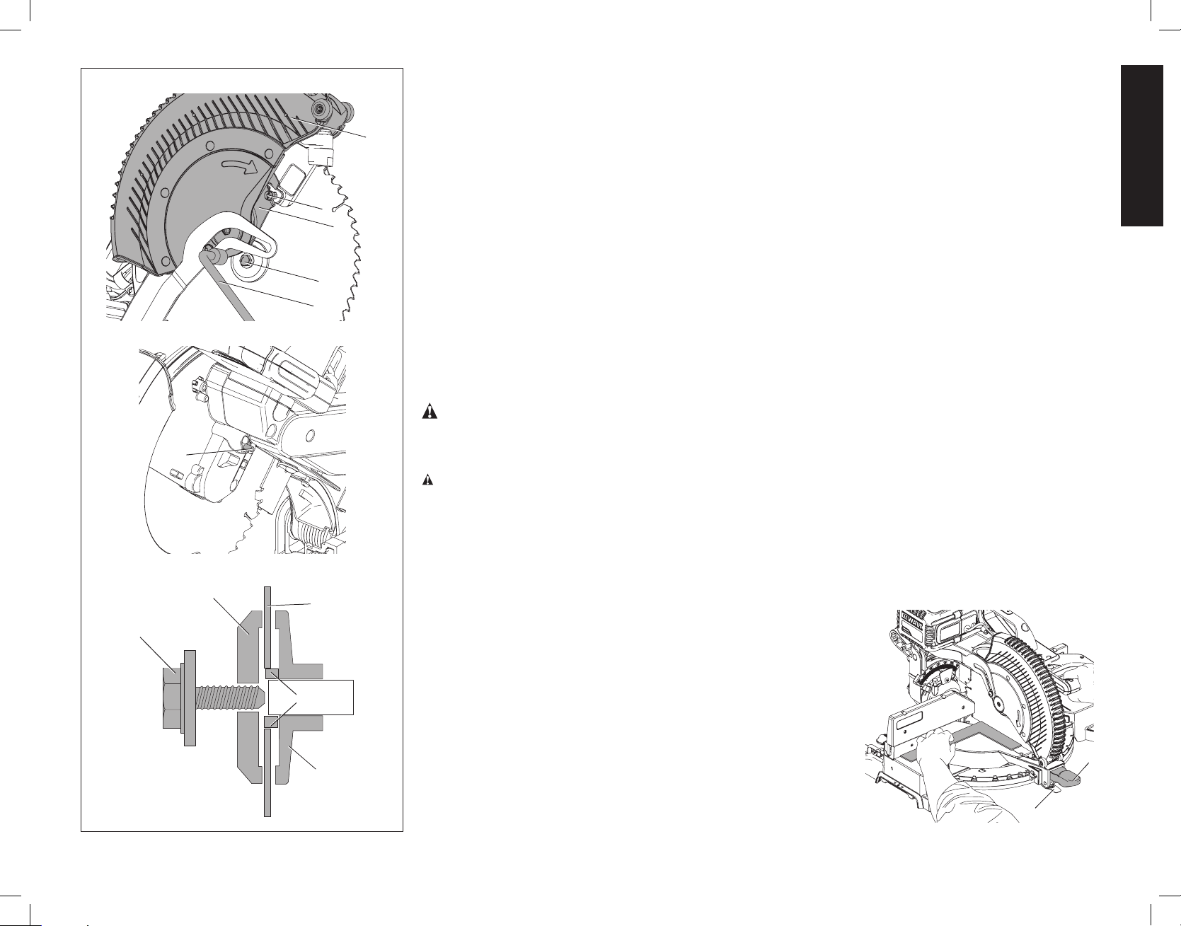
Changing or Installing a New Saw Blade (Fig. 11)
WARNING: To reduce the risk of serious personal injury, turn tool off and remove
the battery packs or power supply before transporting, making any adjustments,
cleaning, repairing, or removing/installing attachments or accessories. An accidental
start-up can cause injury.
WARNING:
• Never depress the spindle lock button while the blade is under power or coasting.
• Do not cut ferrous metal (containing iron or steel) or masonry or fiber cement product
with this miter saw.
• Do not use abrasive wheels or blades.
10
Page 13
English
FIG. 11
AB
AA
AC
AF
V
AD
Z
AB
AE
AT
REMOVING THE BLADE (FIG. 11)
1. Remove the battery packs or power supply.
2. Raise the arm to the upper position and raise the lower guard (D) as far as possible.
3. Loosen, but do not remove guard bracket screw (Z) until the bracket (AT) can be raised far enough to access the blade
D
screw (AB). Lower guard will remain raised due to the position of the guard bracket screw.
4. Depress the spindle lock button (AA) while carefully rotating the saw blade by hand until the lock engages.
5. Keeping the button depressed, use the other hand and the wrench (V) provided to loosen the blade screw (AB). (Turn
clockwise, left-hand threads.)
6. Remove the blade screw (AB), outer blade washer (AC), and blade (AD). The inner blade washer (AE), and if used, the 1"
(25.4mm) blade adapter (AF), may be left on the spindle.
NOTE: For blades with a blade hole of 5/8" (15.88mm), the 1" (25.4mm) blade adapter is not used.
INSTALLING A BLADE (FIG. 11)
1. Remove the battery packs or power supply.
2. With the arm raised, the lower guard (D) held open and the guard bracket (AT) raised, place the blade on the spindle, onto
the blade adapter (AF) (if using a blade with a 1" [25.4mm] diameter blade hole) and against the inner blade clamp (AE)
with the teeth at the bottom of the blade pointing toward the back of the saw.
3. Assemble the outer blade clamp onto the spindle.
4. Install the blade screw (AB) (with integral washer) and, engaging the spindle lock, tighten the screw firmly with wrench
provided. (Turn counterclockwise, left-hand threads.)
NOTE: When using blades with a 5/8" (15.88 mm) diameter blade hole, the blade adapter will not be used and should be stored
in a safe place for future use. The separate blade adapter is not available on all models.
5. Return the guard bracket to its original position and firmly tighten the guard bracket screw (Z) to hold bracket in place.
WARNING: The guard bracket must be returned to its original position and the guard bracket screw
tightened before activating the saw. Failure to do so may allow the guard to contact the spinning saw blade
resulting in damage to the saw and severe personal injury.
ADJUSTMENTS
WARNING: To reduce the risk of serious personal injury, turn tool off and remove the battery packs or power
supply before transporting, making any adjustments, cleaning, repairing, or removing/installing attachments or
accessories. An accidental start-up can cause injury.
Your miter saw is fully and accurately adjusted at the factory at the time of manufacture. If readjustment due to shipping and
handling or any other reason is required, follow the instructions below to adjust your saw.
Once made, these adjustments should remain accurate. Take a little time now to follow these directions carefully to maintain the
accuracy of which your saw is capable.
MITER SCALE (FIG. 12)
Place a square against the saw’s fence and blade. (Do not touch the tips of the blade
teeth with the square. To do so will cause an inaccurate measure ment.) Unlock
miter lock lever (F) and swing the miter arm until the miter latch locks it at the 0
miter position. Do not lock miter lock lever (F). If the saw blade is not exactly
perpendicular to the fence, loosen the three screws (L) that hold the miter scale
(K) to the base and move the scale left or right until the blade is perpendicular to
the fence, as measured with the square. Retighten the three screws. Pay no
attention to the reading of the miter pointer at this time.
MITER POINTER (FIG. 7, 12)
To unlock, lift the miter lock lever (F) up and squeeze the miter release lever (G) to
move the miter arm to the zero position. With the miter lock lever unlocked allow
the miter latch to snap into place as you rotate the miter arm to zero. Observe
the pointer and miter scale through the viewing opening shown in Figure 7. If the
pointer does not indicate exactly zero, loosen the screw holding the pointer in
place, reposition the pointer and tighten the screw.
FIG. 12
F
G
11
Page 14
English
MITER LOCK (FIG. 13)
The miter lock rod should be adjusted if the table of the saw can be moved when the miter
lock handle is locked down. To adjust, put the miter lock handle in the up position. Using
a slotted screwdriver, adjust the lock rod in 1/8 clockwise turn increments to increase the
lock force. To ensure the miter lock is functioning properly, re-lock miter lock handle to a
non-detent miter angle.
FIG. 13
BEVEL SQUARE TO TABLE ADJUSTMENT (FIG. 9, 10, 14)
To align the blade square to the rotary table, lock the
arm in the down position. Place a square against the
blade taking care to not have the square on top of a
tooth. Loosen the bevel lock knob (W) and ensure
the arm is firmly against the 0º bevel stop. Move the
0º bevel stop screw (AJ, Fig. 10) (one on either side
of the saw) as necessary so that the blade is at 0º
bevel to the table.
BEVEL POINTER (FIG. 9)
If the bevel pointer does not indicate zero, loosen
the screw that holds it in place and move the pointer
as necessary. Do not remove the steel plate in front
of the bevel pointer. This plate prevents wood resin
from accumulating on the bevel scale during use.
ADJUSTING THE BEVEL STOP TO 45º LEFT
OR RIGHT (FIG. 10)
NOTE: Adjust the 45º bevel angles only after performing the 0º bevel angle and pointer
adjustment. Ensure the 45º bevel override levers (AI) are pushed inward to obtain an accurate
adjustment.
To adjust the right 45º bevel angle, loosen the bevel lock knob (W) and pull the bevel stop 0º
bevel override knob (AG) to override the 0º bevel stop. When the saw is fully to the right, if
the pointer does not indicate exactly 45º, turn the right bevel stop screw (AJ) until the pointer
indicates 45º.
To adjust the left 45º bevel stop, first loosen the bevel lock knob (W) and tilt the head to the
left. If the pointer does not indicate exactly 45º, turn the left bevel stop screw until the pointer
reads 45º.
ADJUSTING THE BEVEL STOP TO 33.9º (FIG. 10)
NOTE: Adjust the 33.9º bevel angles only after performing the 0º bevel angle and pointer
adjustment.
To set the 33.9º bevel angle, flip out the stop pawls (AH). Loosen the bevel lock knob (W) and
tilt the head to the left. If the pointer does not indicate exactly 33.9º, turn the screw contacting
the pawl until the pointer reads 33.9º.
FIG. 14
To adjust the right 33.9º bevel angle, flip out the stop pawl (AH). Loosen the bevel lock knob
(W) and pull the bevel stop override knob (AG) to override the 0º bevel stop. When the saw is
fully to the right, if the pointer does not indicate exactly 33.9º, turn the screw contacting the
pawl until the pointer indicates 33.9º.
FENCE ADJUSTMENT (FIG. 4)
WARNING: To reduce the risk of serious personal injury, turn tool off and remove
the battery packs or power supply before transporting, making any adjustments,
cleaning, repairing, or removing/installing attachments or accessories. An accidental
start-up can cause injury.
In order that the saw can bevel to many bevel positions, one of the fences (N) may have to
be adjusted to provide clearance. To adjust each fence, loosen the fence adjustment knob
(Y) and slide the fence (N) outward. Make a dry run with the saw turned off and check for
clearance. Adjust the fence to be as close to the blade as practical to provide max imum
workpiece support, without interfering with arm up and down movement. Tighten the fence
adjustment knob (Y) securely. When the bevel operations are complete, don’t forget to
relocate the fence.
For certain cuts, it may be desirable to bring the fences closer to the blade. To use this feature,
back the fence adjustment knobs (Y) out two turns and move the fences closer to the blade
past the normal limit, then tighten the fence adjustment knobs to keep the fences in this
location. When using this feature, make a dry cut first to ensure the blade does not contact
the fences.
NOTE: The tracks of the fences can become clogged with sawdust. If you notice that they are
becoming clogged, use a brush or some low pressure air to clear the guide grooves.
OPERATION
WARNING: To reduce the risk of serious personal injury, turn tool off and remove
the battery packs or power supply before transporting, making any adjustments,
cleaning, repairing, or removing/installing attachments or accessories. An accidental
start-up can cause injury.
WARNING: Always use eye protection. All users and bystanders must wear eye
protection that conforms to ANSI Z87.1 (CAN/CSA Z94.3).
WARNING: To ensure the blade path is clear of obstructions, always make a dry run of the
cut without power before making any cuts on the workpiece.
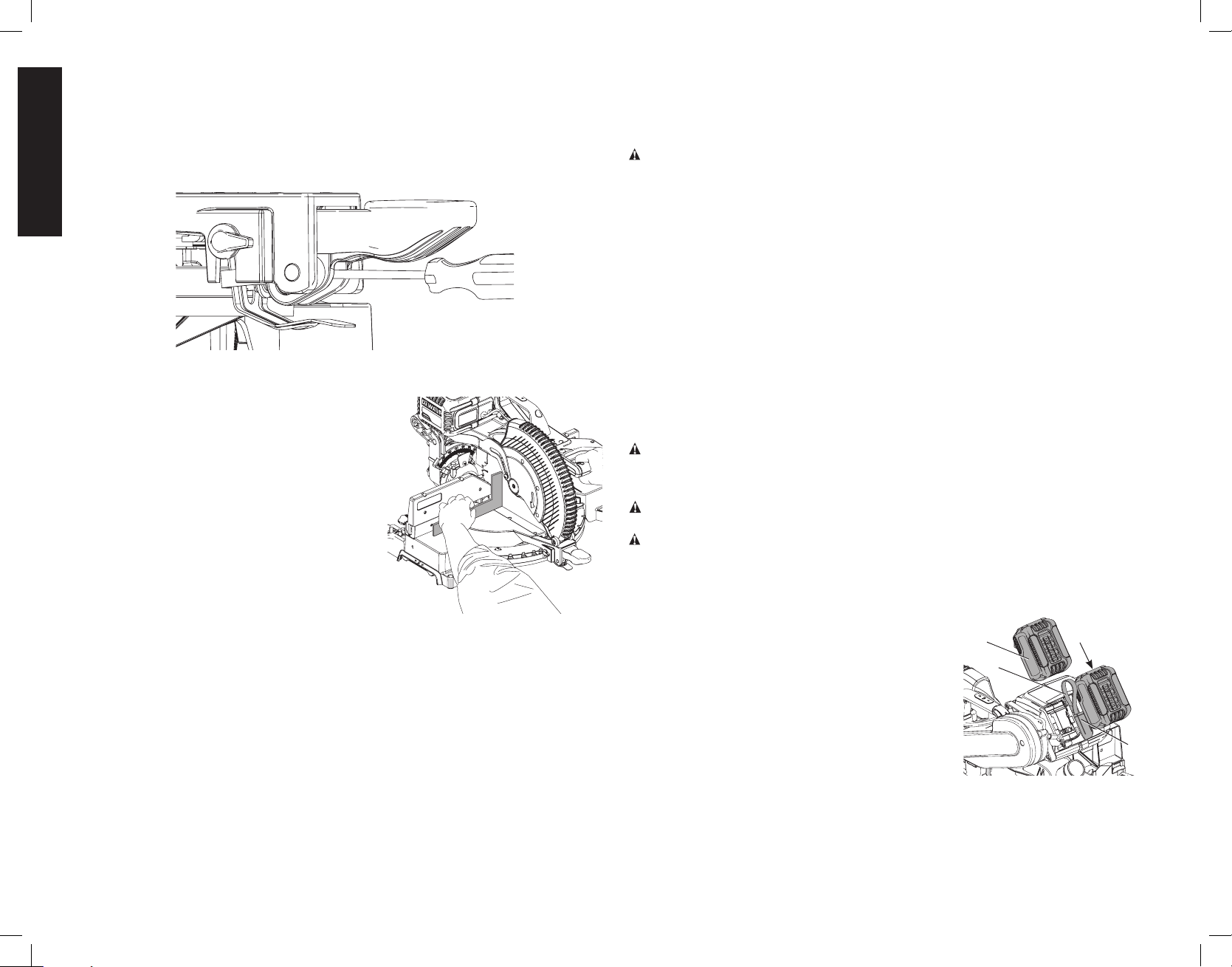
Installing and Removing the Battery Packs (Fig. 15)
NOTE: For best results, make sure your battery packs are fully charged.
To install the battery packs (T) into the tool, align the battery
packs with the rails on the side of the motor housing and
slide them in until they are firmly seated in the tool and
ensure that they do not disengage. Insert the dust cover
(AO) into the corded power supply receptacle (AN) in
between the batteries.
NOTICE: Keep the dust cover in place whenever
the corded power supply is not in use.
To remove the battery packs from the tool, press the
battery release button (AK) and firmly pull the battery
packs out. Insert them into the charger as described in
the charger section of this manual.
FIG. 15
T
AO
AK
Installing and Removing the Corded Power Supply into
and from Tool (Fig.16–18)
Before inserting the corded power supply into your tool, remove the end of the dust cover
(AO) from the tool's corded power supply receptacle (AN). Pull the dust cover away from
the tool’s corded power supply receptacle so that it does not interfere with insertion of the
AN
12
Page 15
English
corded power supply. Inspect the corded power supply receptacle for debris. Debris inside
the receptacle can prevent the corded power supply from fully seating. If debris is present,
clean it using low pressure air. Refer to Cleaning the Corded Power Supply Receptacle.
NOTICE: The corded power supply is for AC power sources only when used with this
tool. Use with DC power sources could result in damage to the tool.
To install the corded power supply into your tool:
1. With the corded power supply unplugged, align
its AC connector with the tool's corded power
FIG. 16
AM
supply receptacle (AN) then snap into place.
2. Ensure that it is fully seated in the tool and does
not disengage.
3. Attach the dust cover (AO) to the dust cover
AO
holder (AP, Fig. 17) in the corded power supply.
4. With the tool turned off, plug the corded power
supply into a standard 120V household electric
power outlet. Do not attempt to use the corded
power supply on any other voltage.
AN
5. Use the tool according to the tool instructions,
making sure the cord is located so that it will
not be stepped on, tripped over, or otherwise
subjected to damage or stress.
To remove the corded power supply from the
tool, first unplug the corded power supply from
the outlet, then press the release button (AM) and
firmly pull the corded power supply out of the tool.
Firmly press the end of the dust cover (AO) into
the tool’s corded power supply receptacle (AN).
FIG. 17
AP
FIG. 18
AQ
FIG. 19A FIG. 19B
PROPER CUT
FIG. 20
IMPROPER CUT
C
B
Trigger Switch (Fig. 18)
To turn the saw on, push the lock-off switch (C) to the left, then depress the trigger switch
(B). The saw will run while the switch is depressed. Allow the blade to spin up to full operating
speed before making the cut. To turn the saw off, release the switch. Allow the blade to stop
before raising the saw head. There is no provision for locking the switch on. A hole (AQ) is
provided in the trigger for insertion of a padlock to lock the switch off.
Always be sure the blade has stopped before removing it from the kerf.
Body and Hand Position (Fig. 19A, 19B, 20)
Proper positioning of your body and hands is crucial when operating the miter saw. Never
place hands inside the cutting area between the two red lines on the base (Fig. 19B) while
the blade is turning. Clamp or hold the workpiece tightly to the table and the fence when
cutting. Keep both hands in position until the trigger has been released and the blade has
completely stopped. ALWAYS MAKE DRY RUNS (UNPOWERED) BEFORE FINISH CUTS SO
THAT YOU CAN CHECK THE PATH OF THE BLADE. DO NOT CROSS HANDS, AS SHOWN
IN FIGURE 20.
13
PROPER CUT
IMPROPER CUT
IMPROPER CUT
Page 16

English
Keep both feet firmly on the floor and maintain proper balance. As you move the miter arm
left and right, follow it and stand slightly to the side of the saw blade. Sight through the guard
louvers when following a pencil line.
Cutting With Your Saw
WARNING: To reduce the risk of serious personal injury, turn tool off and remove
the battery packs or power supply before transporting, making any adjustments,
cleaning, repairing, or removing/installing attachments or accessories. An accidental
start-up can cause injury.
NOTE: Although this saw will cut wood and many non-ferrous materials, we will limit our
discussion to the cutting of wood only. The same guidelines apply to the other materials.
DO NOT CUT FERROUS (IRON AND STEEL) MATERIALS, MASONRY OR FIBER
CEMENT WITH THIS SAW. Do not use any abrasive blades.
QUALITY OF CUT
The smoothness of any cut depends on a number of variables. Things like material being cut, blade
type, blade sharpness and rate of cut all contribute to the quality of the cut.
When smoothest cuts are desired for molding and other precision work, a sharp (60 tooth
carbide) blade and a slower, even cutting rate will produce the desired results.
Ensure that material does not creep while cutting, clamp it securely in place. Always let the
blade come to a full stop before raising arm.
If small fibers of wood still split out at the rear of the workpiece, stick a piece of masking tape
on the wood where the cut will be made. Saw through the tape and carefully remove tape
when finished.
For varied cutting applications, refer to the list of recommended saw blades for your saw and
select the one that best fits your needs. Refer to Saw Blades under Optional Accessories.
CLAMPING THE WORKPIECE
WARNING: A workpiece that is clamped, balanced and secure before a cut may become
unbalanced after a cut is completed. An unbalanced load may tip the saw or anything the
saw is attached to, such as a table or workbench. When making a cut that may become
unbalanced, properly support the workpiece and ensure the saw is firmly bolted to a stable
surface.
WARNING: The clamp foot must remain clamped above the base of the saw whenever
the clamp is used. Always clamp the workpiece to the base of the saw–not to any other part
of the work area. Ensure the clamp foot is not clamped on the edge of the base of the saw.
WARNING: Always use a work clamp to maintain control and reduce the risk of workpiece
damage and personal injury.
If you cannot secure the workpiece on the table and against the fence by hand, (irregular
shape, etc.) or your hand would be less than 6" (152mm) from the blade, a clamp or other
fixture must be used.
For best results use a DeWALT clamp made for use with your saw. It is available for purchase
at your local retailer or DeWALT service center.
Other aids such as spring clamps, bar clamps or C-clamps may be appropriate for certain
sizes and shapes of material. Use care in selecting and placing these clamps. Take time to
make a dry run before making the cut. The left or right fence will slide from side to side to aid
in clamping.
TO INSTALL CLAMP (OPTIONAL ACCESSORY)
1. Insert it into the hole (X, Fig. 4) behind the fence. The clamp should be facing toward the
back of the miter saw. The groove on the clamp rod should be fully inserted into the base.
Ensure this groove is fully inserted into the base of the miter saw. If the groove is visible,
the clamp will not be secure.
2. Rotate the clamp 180º toward the front of the miter saw.
3. Loosen the knob to adjust the clamp up or down, then use the fine adjust knob to firmly
clamp the workpiece.
NOTE: Place the clamp on the opposite side of the base when beveling. ALWAYS MAKE
DRY RUNS (UNPOWERED) BEFORE FINISH CUTS TO CHECK THE PATH OF THE BLADE.
ENSURE THE CLAMP DOES NOT INTERFERE WITH THE ACTION OF THE SAW OR
GUARDS.
SUPPORT FOR LONG PIECES
ALWAYS SUPPORT LONG PIECES.
Never use another person as a substitute for a table extension; as additional support for a
workpiece that is longer or wider than the basic miter saw table or to help feed, support or
pull the workpiece.
For best results, use the DW7080 extension work support or a miter saw stand with an
extension work support. These are available from your dealer at extra cost.
Support long workpieces using any convenient means such as sawhorses or similar devices
to keep the ends from dropping.
CROSSCUTS
Cutting of multiple pieces is not recommended but can be done safely by ensuring that
each piece is held firmly against the table and fence. A crosscut is made by cutting wood
across the grain at any angle. A straight crosscut is made with the miter arm at the zero
degree position. Set the miter arm at zero, hold the wood on the table and firmly against
the fence. Turn on the saw by squeezing the trigger.
WARNING: Always use a work clamp to maintain control and reduce the risk of workpiece
damage and personal injury.
When the saw comes up to speed (about 1 second) lower the arm smoothly and slowly to cut
through the wood. Let the blade come to a full stop before raising arm.
Miter crosscuts are made with the miter arm at some angle other than zero. This angle is often
45° for making corners, but can be set anywhere from zero to 50° left or right. After selecting the
desired miter angle, be sure to lock miter lock lever. Make the cut as described above.
To cut through an existing pencil line on a piece of wood, match the angle as close as
possible. Cut the wood a little too long and measure from the pencil line to the cut edge to
determine which direction to adjust the miter angle and recut. This will take some practice,
but it is a commonly used technique.
BEVEL CUTS
A bevel cut is a crosscut made with the saw blade at a bevel to the wood. In order to set the
bevel, loosen the bevel clamp knob and move the saw to the left as desired. (It is necessary
to move the fence to allow clearance). Once the desired bevel angle has been set, tighten the
bevel clamp knob firmly.
Bevel angles can be set from 48° right to 48° left and can be cut with the miter arm set
between zero and 50° right or left. At some extreme angles, the right or left side fence might
have to be removed. To remove the left or right fence, unscrew the knobs several turns and
slide the fence out.
CUTTING PICTURE FRAMES, SHADOW BOXES AND OTHER FOUR-SIDED
PROJECTS
To best understand how to make the items listed here, we suggest that you try a few simple
projects using scrap wood until you develop a “FEEL” for your saw.
Your saw is the perfect tool for mitering corners like the one shown in Figure 21. Diagram A
in Figure 22 shows a joint made by using the bevel adjustment to bevel the edges of the two
boards at 45° each to produce a 90° corner. For this joint the miter arm was locked in the
zero position and the bevel adjustment was locked at 45°. The wood was positioned with the
broad flat side against the table and the narrow edge against the fence. The cut could also
be made by mitering right and left with the broad surface against the fence.
14
Page 17
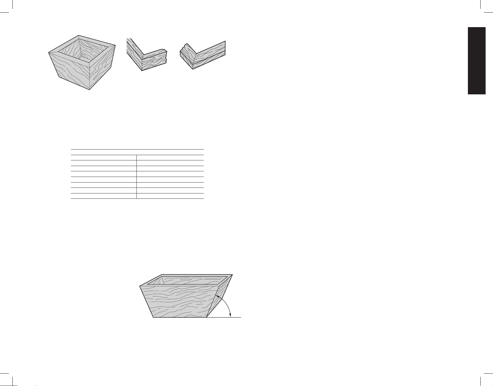
English
FIG. 21 FIG. 22
A
B
CUTTING TRIM MOLDING AND OTHER FRAMES
Diagram B in Figure 22 shows a joint made by setting the miter arm at 45° to miter the two
boards to form a 90° corner. To make this type of joint, set the bevel adjustment to zero and
the miter arm to 45°. Once again, position the wood with the broad flat side on the table and
the narrow edge against the fence.
The two Diagrams in Figure 22 are for four side objects only.
As the number of sides changes, so do the miter and bevel angles. The chart below gives the
proper angles for a variety of shapes.
- EXAMPLES -
NO. SIDES ANGLE MITER OR BEVEL
4 45°
5 36°
6 30°
7 25.7°
8 22.5°
9 20°
10 18°
(The chart assumes that all sides are of equal length.) For a shape that is not shown in the
chart, use the following formula. 180° divided by the number of sides equals the miter (if the
material is cut vertically) or bevel angle (if the material is cut laying flat).
CUTTING COMPOUND MITERS
A compound miter is a cut made using a miter angle and a bevel angle at the same time.
This is the type of cut used to make frames or boxes with slanting sides like the one shown
in Figure23.
NOTE: If the cutting angle varies from cut to cut, check that the bevel clamp knob and the
miter lock knob are securely tightened. These knobs must be tightened after making any
changes in bevel or miter.
The chart (TABLE 1) will assist you in selecting the
FIG. 23
proper bevel and miter settings for common
compound miter cuts. To use the chart,
select the desired angle “A” (Figure 23) of
your project and locate that angle on the
appropriate arc in the chart. From that point
follow the chart straight down to find the
correct bevel angle and straight across to
find the correct miter angle.
Set your saw to the prescribed angles and
ANGLE “A”
make a few trial cuts. Practice fitting the
cut pieces together until you develop a feel for this procedure and feel comfortable with it.
Example: To make a four-sided box with 26° exterior angles (Angle A, Figure 23), use the
upper right arc. Find 26° on the arc scale. Follow the horizontal intersecting line to either side
to get miter angle setting on saw (42°). Likewise, follow the vertical intersecting line to the top or
bottom to get the bevel angle setting on the saw (18°). Always try cuts on a few scrap pieces
of wood to verify settings on saw.
CUTTING BASE MOLDING
ALWAYS MAKE A DRY RUN WITHOUT POWER BEFORE MAKING ANY CUTS.
Straight 90° cuts:
Position the wood against the fence and hold it in place as shown in Figure 24. Turn on
the saw, allow the blade to reach full speed and lower the arm smoothly through the cut.
CUTTING BASE MOLDING UP TO 6" (152MM) VERTICALLY AGAINST THE FENCE
Position material as shown in Figure 24.
All cuts made with the back of the molding against the fence and bottom of the molding
against the base.
INSIDE CORNER: OUTSIDE CORNER:
Left side Left side
1. Miter left 45 1. Miter right at 45°
2. Save left side of cut 2. Save left side of cut
Right side Right side
1. Miter Right 45° 1. Miter left at 45°
2. Save right side of cut 2. Save right side of cut
Material up to 6"(152mm) can be cut as described above.
CUTTING CROWN MOLDING
Your miter saw is better suited to the task of cutting crown molding than any tool made.
In order to fit properly, crown molding must be compound mitered with extreme accuracy.
The two flat surfaces on a given piece of crown molding are at angles that, when added
together, equal exactly 90°. Most, but not all, crown molding has a top rear angle (the section
that fits flat against the ceiling) of 52° and a bottom rear angle (the part that fits flat against
the wall) of38°.
Your miter saw has special pre-set miter latch points at 31.62° left and right for cutting crown
molding at the proper angle and bevel stop pawls at 33.9º left and right. There is also a mark
on the bevel scale at 33.9°.
The Bevel Setting/Type of Cut chart gives the proper settings for cutting crown molding.
(The numbers for the miter and bevel settings are very precise and are not easy to accurately
set on your saw.) Since most rooms do not have angles of precisely 90°, you will have to fine
tune your settings anyway.
PRETESTING WITH SCRAP MATERIAL IS EXTREMELY IMPORTANT!
INSTRUCTIONS FOR CUTTING CROWN MOLDING LAYING FLAT AND USING THE
COMPOUND FEATURES
1. Molding laying with broad back surface down flat on saw table (Figure 25).
2. The settings below are for All Standard (U.S.) crown molding with 52° and 38° angles.
15
Page 18
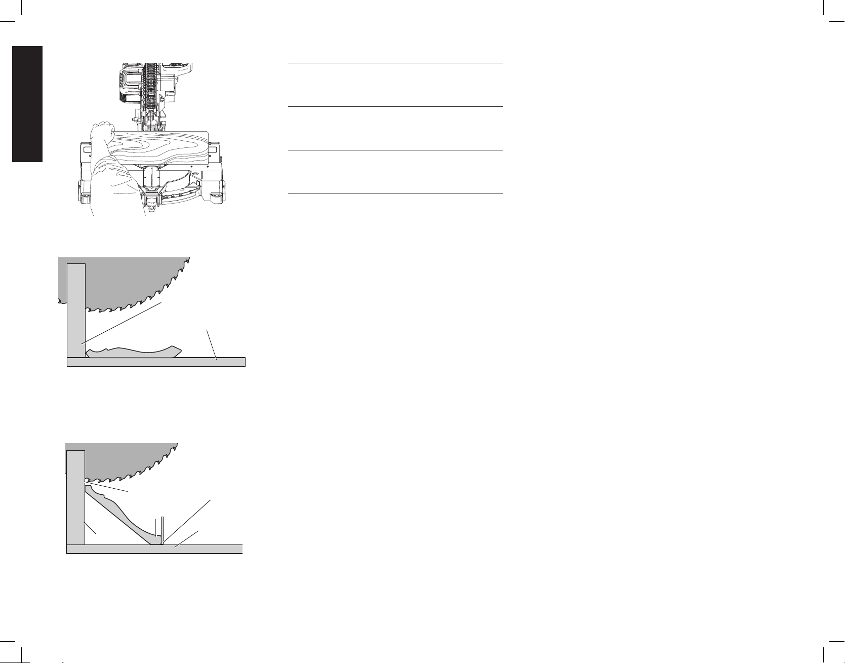
English
FIG. 24
FIG. 25
FIG. 26
FENCE
TABLE
CROWN MOLDING FLAT ON TABLE AND
CROWN MOLDING BETWEEN FENCE
AGAINST FENCE
BOTTOM SIDE
OF MOLDING
FENCE
AND TABLE
DW7084
CROWN
MOLDING
FENCE
TOP SIDE
OF MOLDING
TABLE
BEVEL SETTING TYPE OF CUT
33.9° Left LEFT SIDE, INSIDE CORNER
1. Top of molding against fence
2. Mitre table set right 31.62°
3. Save left end of cut
33.9° Right RIGHT SIDE, INSIDE CORNER
1. Top of molding against fence
2. Miter table set right 31.62°
3. Save right end of cut
33.9° Right LEFT SIDE, OUTSIDE CORNER
1. Top of molding against fence
2. Miter table set at left 31.62°
3. Save left end of cut
33.9° Left RIGHT SIDE, OUTSIDE CORNER
1. Top of molding against fence
2. Mitre table set right 31.62
3. Save right end of cut°
When setting bevel and miter angles for all compound miters,
remember that:
The angles presented for crown moldings are very precise and
difficult to set exactly. Since they can easily shift slightly and very
few rooms have exactly square corners, all settings should be
tested on scrap molding.
PRETESTING WITH SCRAP MATERIAL IS EXTREMELY
IMPORTANT!
ALTERNATIVE METHOD FOR CUTTING CROWN
MOLDING
Place the molding on the table at an angle between the fence
and the saw table, as shown in Figure 26. Use of the crown
molding fence accessory (DW7084) is highly recommended
because of its degree of accuracy and convenience. The crown
molding fence accessory is available for purchase from your
local dealer.
The advantage to cutting crown molding using this method is
that no bevel cut is required. Minute changes in the miter angle
can be made without affecting the bevel angle. This way, when
corners other than 90° are encountered, the saw can be quickly
and easily adjusted for them. Use the crown molding fence
accessory to maintain the angle at which the molding will be on
the wall.
INSTRUCTIONS FOR CUTTING CROWN MOLDING
ANGLED BETWEEN THE FENCE AND BASE OF THE
SAW FOR ALL CUTS
1. Angle the molding so the bottom of the molding (part which
goes against the wall when installed) is against the fence and
the top of the molding is resting on the base of the saw, as
shown in Figure 26.
2. The angled “flats” on the back of the molding must rest
squarely on the fence and base of the saw.
INSIDE CORNER: OUTSIDE CORNER:
Left side Left side
1. Miter right 45 1. Miter left at 45°
2. Save right side of cut 2. Save right side of cut
Right side Right side
1. Miter left 45° 1. Miter right at 45°
2. Save left side of cut 2. Save left side of cut
Special Cuts
NEVER MAKE ANY CUT UNLESS THE MATERIAL IS
SECURED ON THE TABLE AND AGAINST THE FENCE.
ALUMINUM CUTTING
ALWAYS USE THE APPROPRIATE SAW BLADE MADE
ESPECIALLY FOR CUTTING ALUMINUM. These are available
at your local DeWALT retailer or DeWALT service center. Certain
workpieces, due to their size, shape or surface finish, may
require the use of a clamp or fixture to prevent movement
during the cut. Position the material so that you will be cutting
the thinnest cross section, as shown in Figure27. Figure 28
illustrates the wrong way to cut these extrusions. Use a stick
wax cutting lubricant when cutting aluminum. Apply the stick
wax directly to the saw blade before cutting. Never apply stick
wax to a moving blade.
The wax, available at most hardware stores and industrial mill
supply houses, provides proper lubrication and keeps chips
from adhering to the blade.
Be sure to properly secure workpiece.
Refer to Saw Blades under Optional Accessories for correct
saw blade.
BOWED MATERIAL
When cutting bowed material always position it as shown in
Figure 29 and never like that shown in Figure 30. Positioning
the material incorrectly will cause it to pinch the blade near the
completion of the cut.
CUTTING PLASTIC PIPE OR OTHER ROUND MATERIAL
Plastic pipe can be easily cut with your saw. It should be cut just
like wood and CLAMPED OR HELD FIRMLY TO THE FENCE
TO KEEP IT FROM ROLLING. This is extremely important
when making angle cuts.
CUTTING LARGE MATERIAL
Occasionally you will encounter a piece of wood a little too large
to fit beneath the blade guard. If this occurs, simply place your
right thumb on the upper side of the guard and roll the guard
up just enough to clear the workpiece, as shown in Figure 31.
Release the lower blade guard before turning the saw on and
beginning the cut. Avoid doing this as much as possible, but
if need be, the saw will operate properly and make the bigger
cut. NEVER TIE, TAPE, OR OTHERWISE HOLD THE GUARD
16
Page 19
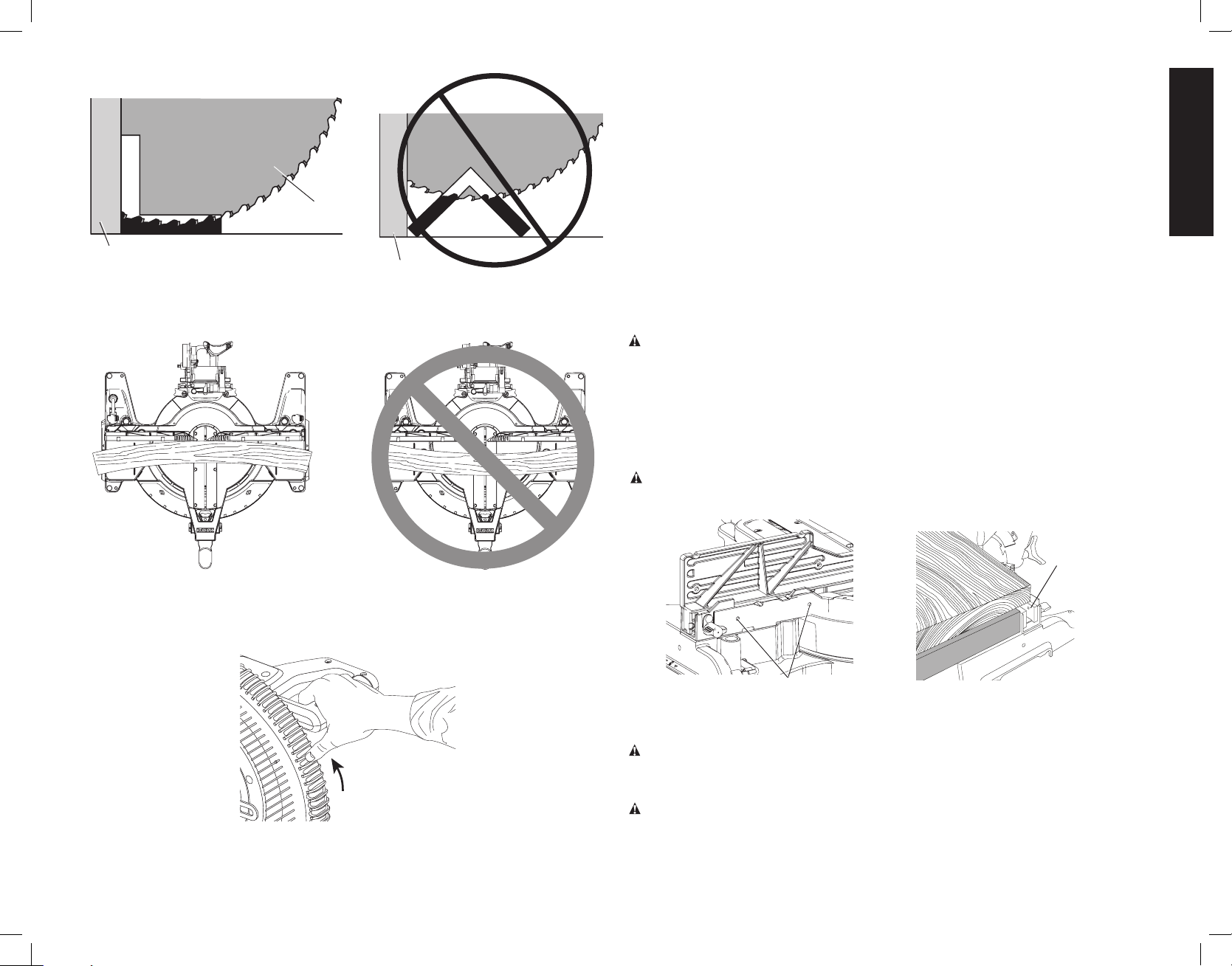
English
FIG. 27
FENCE
FIG. 29
RIGHT
BLADE
FIG. 28
FIG. 30
FENCE
WRONG
BLADE
OPEN WHEN OPERATING THIS SAW. NEVER RAISE THE LOWER GUARD ASSEMBLY
MANUALLY UNLESS THE BLADE IS STOPPED.
SPECIAL SET-UP FOR WIDE CROSSCUTS
Your saw can cut very wide [up to 10" (406mm)] workpieces when a special set up is used.
To set the saw up for these workpieces, follow these steps:
1. Remove both left and right sliding fences from the saw and set aside. To remove them,
unscrew the fence knobs several turns and slide each fence outward. Adjust and lock the
miter control so that it is at 0° miter.
2. Make a platform using a piece of 1.5 inch (38mm) thick particleboard or similar flat strong
1.5" (38mm) thick wood to the dimensions: 10" x 24" (254 x 610mm). The platform must
be flat otherwise the material could move during cutting and cause injury.
3. Mount the 10" x 24" (254 x 610mm) platform to the saw using 4 three-inch (76 mm) long
wood screws through the holes in the base fence (Fig. 32). Four screws must be used to
properly secure the material. When the special set up is used, the platform will be cut into
two pieces. Ensure the screws are tightened properly otherwise material could loosen and
cause injury. Ensure the platform is firmly flat on the table, against the fence, and centered
evenly from left to right.
WARNING: Ensure the saw is mounted firmly to a stable flat surface. Failure to do so
could cause the saw to be unstable and fall causing personal injury.
4. Place the workpiece to be cut on top of the platform mounted to the table. Ensure the
workpiece is firmly against the backfence (Fig. 33).
5. Secure the material before cutting. Cut slowly through the material. Failure to clamp
securely or cut slowly could result in the material coming loose and causing injury.
After several cuts are made at various miter angles other than 0º, the platform may weaken
and not properly support the work. Install a new, unused platform to the saw after presetting
the desired miter angle.
WARNING: Continued use of a platform with several kerfs may cause loss of material
control and possible injury.
FIG. 32
FIG. 33
CORRECT
BASE
FENCE
INCORRECT
FIG. 31
SCREWS
(two each side)
MAINTENANCE
WARNING: To reduce the risk of serious personal injury, turn tool off and remove
the battery packs or power supply before transporting, making any adjustments,
cleaning, repairing, or removing/installing attachments or accessories. An accidental
start-up can cause injury.
WARNING: To reduce the risk of serious personal injury, DO NOT touch the sharp
points on the blade with fingers or hands while performing any maintenance.
DO NOT use lubricants or cleaners (particularly spray or aerosol) in the vicinity of the plastic
guard. The polycarbonate material used in the guard is subject to attack by certain chemicals.
17
Page 20
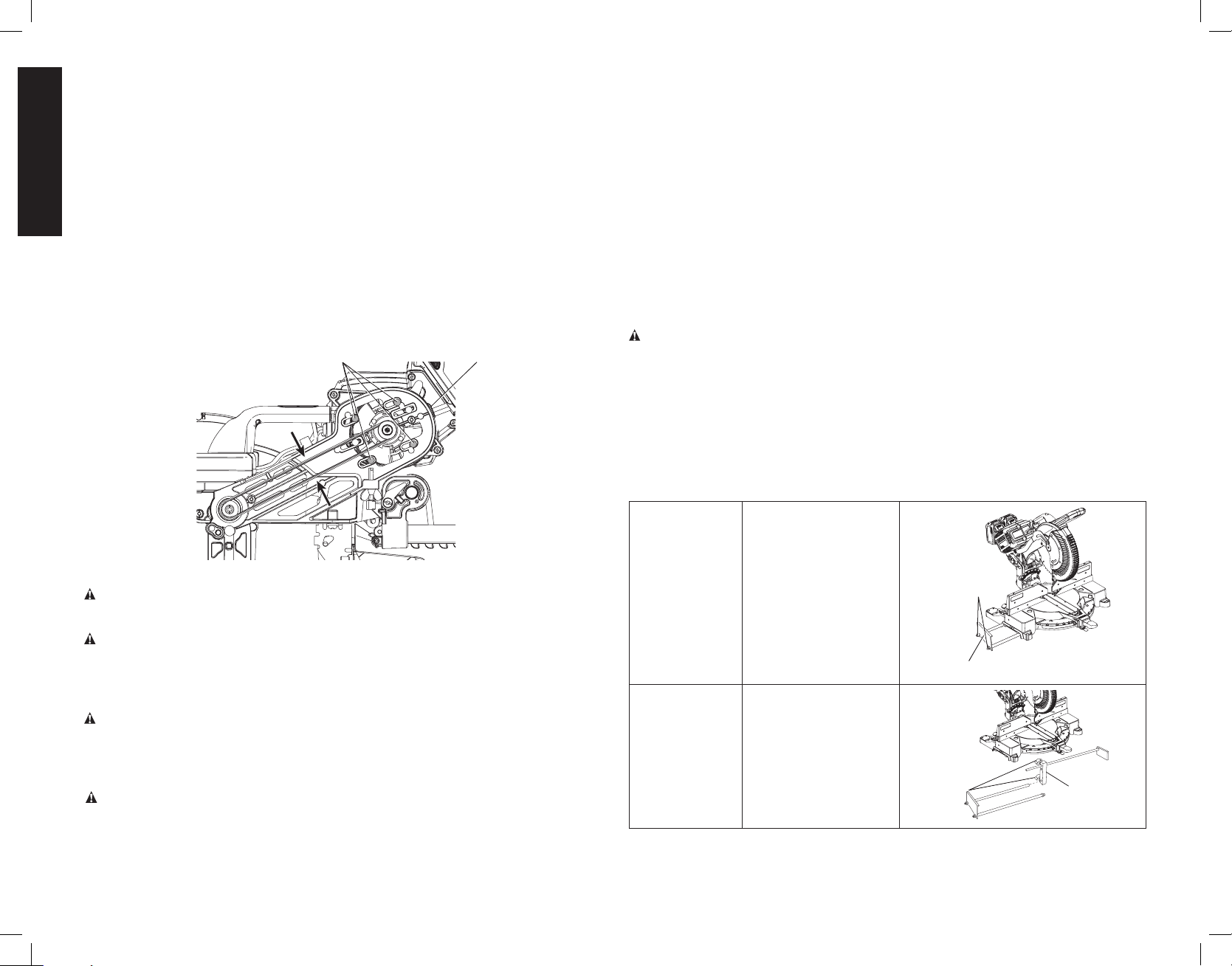
English
• All bearings are sealed. They are lubricated for life and need no further maintenance.
• Periodically clean all dust and wood chips from around AND UNDER the base and the
rotary table. Even though slots are provided to allow debris to pass through, some dust
will accumulate.
• The brushes are designed to give you several years of use. If they ever need replacement,
return the tool to the nearest service center for repair.
Removing and Replacing Belt (Fig. 34)
The belt is designed to last the life of the tool. However, abuse of the tool could cause the
belt to fail.
If the blade does not turn when the motor is running, the belt has failed. To inspect or replace
the belt, remove the belt cover screws. Remove the belt cover. Inspect the ribs of the belt for
wear or failure. Check belt tension by squeezing the belt as shown in Figure 34. The belt halves
should almost touch when squeezing firmly with the thumb and index finger.
To adjust the tension, loosen, but do not remove, the four cross head screws shown (AR).
Then rotate the set screw (AS) on the top of the motor plate casting until the proper tension
is achieved. Tighten the four screws securely and replace the belt cover.
NOTE: Over tightening the belt will cause premature motor failure.
FIG. 34
AR
AS
Cleaning
WARNING: Blow dirt and dust out of all air vents and guard mechanisms (if applicable) with
clean, dry air at least once a week. To minimize the risk of eye injury, always wear ANSI Z87.1
approved eye protection and respiratory protection when performing this.
WARNING: Never use solvents or other harsh chemicals for cleaning the non-metallic parts
of the tool. These chemicals may weaken the plastic materials used in these parts. Use a
cloth dampened only with water and mild soap. Never let any liquid get inside the tool; never
immerse any part of the tool into a liquid.
CLEANING THE DEWALT CORDED POWER SUPPLY
WARNING: Never use solvents or other harsh chemicals for cleaning the non-metallic parts
of the tool. These chemicals may weaken the plastic materials used in these parts. Use a
cloth dampened only with water and mild soap. Never let any liquid get inside the tool; never
immerse any part of the tool into a liquid.
CLEANING THE CORDED POWER SUPPLY RECEPTACLE
WARNING: Blow debris out of the corded power supply receptacle (AN, Fig. 16) with
clean, dry air. To minimize the risk of eye injury, always wear ANSI Z87.1 approved eye
protection and respiratory protection when performing this.
DUST DUCT CLEANING
Depending on your cutting environment, saw dust can clog the dust duct and may prevent
dust from flowing away from the cutting area properly. With the battery pack or corded power
supply removed and the saw head raised fully, low pressure air or a large diameter dowel rod
can be used to clear the dust out of the dust duct.
CUTLINE™ LED WORKLIGHT CLEANING
For the best worklight performance, perform the following maintenance regularly with the
battery or corded power supply removed.
• Carefully clean sawdust and debris from worklight lens with a cotton swab.
• DO NOT use solvents of any kind, they may damage the lens.
• Dust build-up can block the worklight and prevent it from accurately indicating the line of
cut.
• Follow miter saw’s instruction manual to remove and install blade.
• With blade removed from saw, clean pitch and build-up from blade. Pitch and debris can
interfere with the worklight and prevent it from accurately indicating the line of cut.
Accessories
WARNING: Since accessories, other than those offered by DeWALT, have not been tested
with this product, use of such accessories with this tool could be hazardous. To reduce the
risk of injury, only DeWALT recommended accessories should be used with this product.
Recommended accessories for use with your tool are available at extra cost from your
local dealer or authorized service center. If you need assistance in locating any accessory,
please contact DeWALT Industrial Tool Co., 701 East Joppa Road, Towson, MD 21286, call
1-800-4-DeWALT (1-800-433-9258) or visit our website: www.dewalt.com.
OPTIONAL ACCESSORIES
The following accessories, designed for your saw, may be helpful. In some cases, other locally
obtained work supports, length stops, clamps, etc., may be more appropriate. Use care in
selecting and using accessories.
Extension
Work Support:
DW7080
Adjustable Length
Stop: DW7051
Used to support long
overhanging work pieces,
the work support is
user assembled. Your
saw base is designed
to accept two work
supports, one on each
side.
Requires the use of one
Extension Work Support
(DW7080). It is used to
make repetitive cuts of
the same length from 0
to 42" (107cm).
LOCKNUTS
END PLATE
KNOBS
BRACKET
18
Page 21
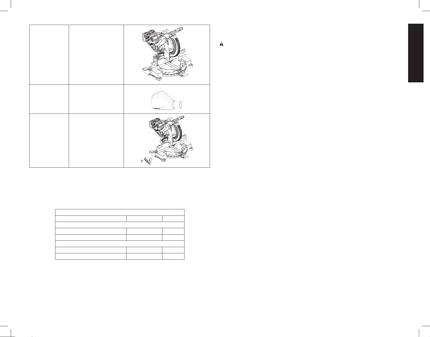
English
Clamp: DW7082 Used for firmly clamping
workpiece to the saw
table for precision cutting.
Dust Bag:
DW7053
(included with
some models)
Crown Molding
Fence: DW7084
Kerf Plate Blank: DW7055 (not shown)
Used to limit back side tear out of material or as a replacement kerf plate.
SAW BLADES: ALWAYS USE 12" (305 mm) SAW BLADES WITH EITHER 1" (25.4 mm) OR
5/8" (15.88 mm) ARBOR HOLES. SPEED RATING MUST BE AT LEAST 4800 RPM. Never
use a smaller diameter blade. It will not be guarded properly. Use crosscut blades only!
Do not use blades designed for ripping, combination blades or blades with hook angles in
excess of 7°.
Equipped with a zipper
for easy emptying, the
dust bag will capture the
majority of the sawdust
produced.
Used for precision cutting
of crown molding.
BLADE DESCRIPTIONS
APPLICATION DIAMETER TEETH
Construction Saw Blades (thin kerf with anti-stick rim)
General Purpose 12" (305 mm) 40
Fine Crosscuts 12" (305 mm) 60
Woodworking Saw Blades (provide smooth, clean cuts)
Fine crosscuts 12" (305 mm) 80
Non-ferrous metals 12" (305 mm) 96
NOTE: For cutting non-ferrous metals, use only saw blades with
TCG (Triple Chip Grind) teeth designed for this purpose.
Repairs
The charger, power supply and battery pack are not serviceable. There are no serviceable parts
inside the charger, power supply and battery pack.
WARNING: To assure product SAFETY and RELIABILITY, repairs, maintenance and
adjustment (including brush inspection and replacement) should be performed by a
DeWALT factory service center or a DeWALT authorized service center. Always use identical
replacementparts.
Service Information
Please have the following information available for all service calls:
Model Number __________________ Serial Number __________________________________
Date and Place of Purchase _______________________________________________________
Register Online
Thank you for your purchase. Register your product now for:
• WARRANTY SERVICE: Registering your product will help you obtain more efficient
warranty service in case there is a problem with your product.
• CONFIRMATION OF OWNERSHIP: In case of an insurance loss, such as fire, flood or
theft, your registration of ownership will serve as your proof of purchase.
• FOR YOUR SAFETY: Registering your product will allow us to contact you in the
unlikely event a safety notification is required under the Federal Consumer Safety Act.
Register online at www.dewalt.com/register.
Three Year Limited Warranty
DeWA LT will repair, without charge, any defects due to faulty materials or workmanship for
three years from the date of purchase. This warranty does not cover part failure due to normal
wear or tool abuse. For further detail of warranty coverage and warranty repair information,
visit www.dewalt.com or call 1-800-4-DeWALT (1-800-433-9258). This warranty does not
apply to accessories or damage caused where repairs have been made or attempted by
others. This warranty gives you specific legal rights and you may have other rights which vary
in certain states or provinces.
In addition to the warranty, DeWALT tools are covered by our:
1 YEAR FREE SERVICE
DeWA LT will maintain the tool and replace worn parts caused by normal use, for free, any time
during the first year after purchase.
2 YEARS FREE SERVICE ON DeWALT BATTERY PACKS
DC9071, DC9091, DC9096, DC9182, DC9280, DC9360,
DCB120, DCB127, DCB201, DCB203, DCB203BT, DCB207, DCB361
3 YEARS FREE SERVICE ON DeWALT BATTERY PACKS
DCB200, DCB204, DCB204BT, DCB205, DCB606
DeWALT BATTERY PACKS
Product warranty voided if the battery pack is tampered with in any way. DeWA LT is not
responsible for any injury caused by tampering and may prosecute warranty fraud to the
fullest extent permitted by law.
90 DAY MONEY BACK GUARANTEE
If you are not completely satisfied with the performance of your DeWA LT Power Tool, Laser, or
Nailer for any reason, you can return it within 90 days from the date of purchase with a receipt
for a full refund – no questions asked.
19
Page 22
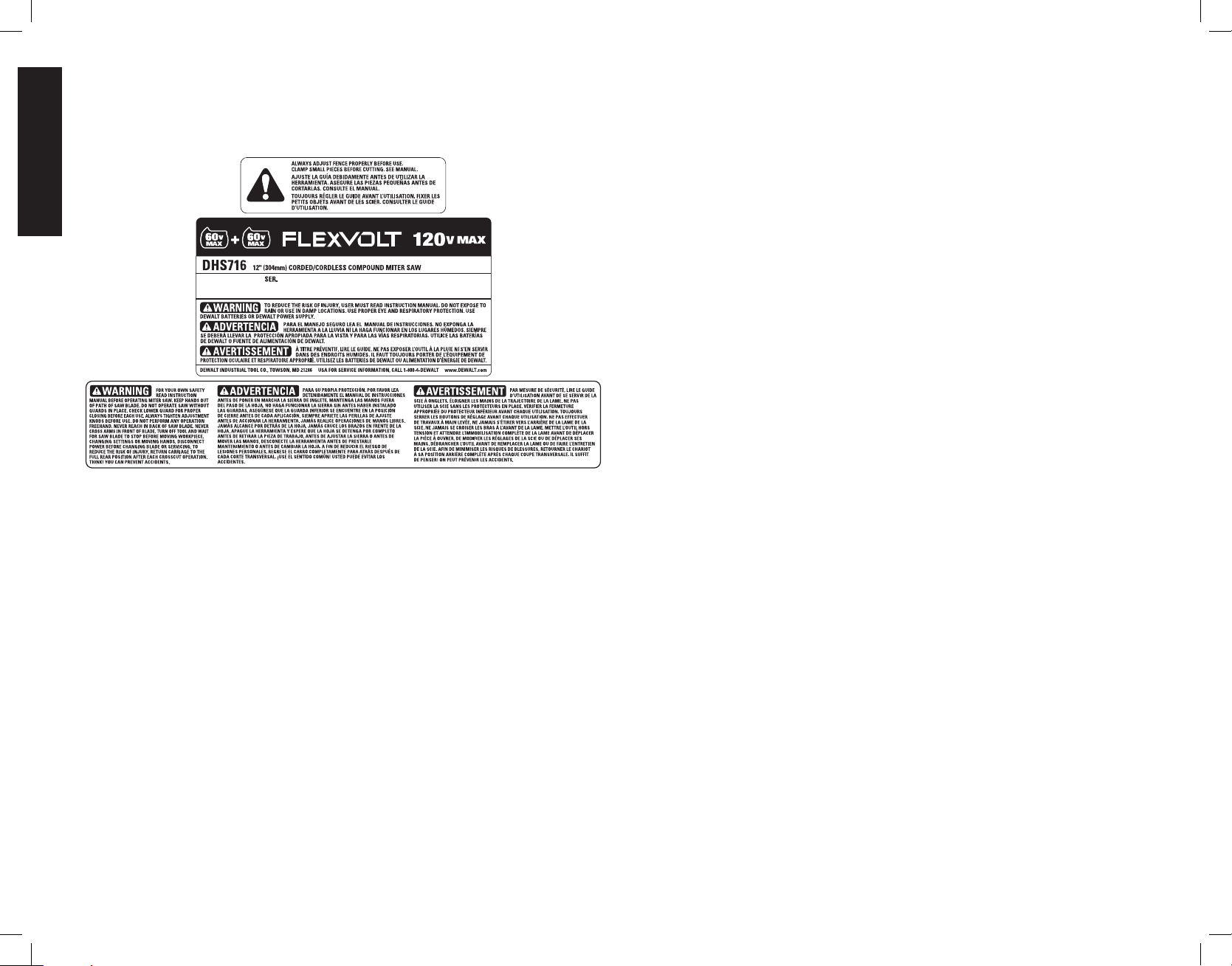
English
LATIN AMERICA: This warranty does not apply to products sold in Latin America. For
products sold in Latin America, see country specific warranty information contained in the
packaging, call the local company or see website for warranty information.
FREE WARNING LABEL REPLACEMENT: If your warning labels become illegible or are
missing, call 1-800-4-DeWALT (1-800-433-9258) for a free replacement.
20
Page 23

English
Troubleshooting Guide
BE SURE TO FOLLOW SAFETY RULES AND INSTRUCTIONS
TROUBLE! WHAT’S WRONG? WHAT TO DO
Saw will not start 1. Battery or power supply not installed 1. Install battery or power supply. Refer to Installing and Removing the Battery Packs or Installing
and Removing the Corded Power Supply into and from Tool.
2. Battery or power supply not fully inserted 2. Check that battery or power supply are fully latched. Check AC adapter plug in the motor housing for
debris. Refer to Cleaning the Corded Power Supply Receptacle.
3. Batteries not charged 3. Charge batteries. Refer to Charging a Battery.
4. Power supply not plugged in 4. Plug in saw.
5. Cord damaged 5. Have cord replaced by authorized service center.
6. Fuse blown or breaker tripped 6. Replace fuse or reset circuit breaker.
7. Saw overheated 7. Wait several minutes for saw to cool.
8. Batteries overheated 8. Wait several minutes for batteries to cool.
Saw makes
unsatisfactory cuts
Blade does not come up
to speed
Machine vibrates excessively 1. Saw not mounted securely to stand or
Does not make accurate
miter cuts
Material pinches blade 1. Cutting bowed material 1. Refer to Bowed Material under Special Cuts.
CUTLINE™ worklight flashing 1. Battery low on charge 1. Charge batteries. Refer to Charging a Battery.
1. Dull blade 1. Replace blade. Refer to Changing or Installing a New Saw Blade.
2. Blade mounted backwards 2. Turn blade around. Refer to Changing or Installing a New Saw Blade.
3. Gum or pitch on blade 3. Remove blade and clean with turpentine and coarse steel wool or household oven cleaner.
4. Incorrect blade for work being done 4. Change the blade type. Refer to Saw Blades under Accessories.
1. Extension cord too light or too long 1. Replace with adequate size cord. Refer to Important Safety Instructions for All Battery
Chargers.
2. Low house current 2. Contact your electric company.
1. Tighten all mounting hardware. Refer to Bench Mounting.
work bench
2. Stand or bench on uneven floor 2. Reposition on flat level surface. Refer to Familiarization.
3. Damaged saw blade 3. Replace blade. Refer to Changing or Installing a New Saw Blade.
1. Miter scale not adjusted correctly 1. Check and adjust. Refer to Miter Scale under Adjustments.
2. Miter pointer not adjusted correctly 2. Check and adjust. Refer to Miter Pointer under Adjustments.
3. Workpiece is not perpendicular to table 3. Check and adjust fence. Refer to Fence Adjustment under Adjustments.
4. Workpiece moving 4. Clamp workpiece securely to fence or glue 120 grit sandpaper to fence with rubber cement.
2. Battery hot 2. Wait several minutes for batteries to cool.
21
Page 24

English
(POSITION WOOD WITH BROAD FLAT SIDE ON THE TABLE AND THE NARROW EDGE AGAINST THE FENCE)
10
20
30
40
TABLE 1: COMPOUND MITER CUT
SQUARE BOX
50
10
20
30
60
40
6-SIDED BOX
10
20
SET THIS MITER ANGLE ON SAW
30
8-SIDED BOX
40
50
70
ANGLE OF SIDE OF BOX (ANGLE A)
60
50
60
70
80
70
80
80
SET THIS BEVEL ANGLE ON SAW
22
Page 25

Français
Définitions: symboles et termes d'alarmes sécurité
Ces guides d'utilisation utilisent les symboles et termes d'alarmes sécurité suivants
pour vous prévenir de situations dangereuses et de risques de dommages corporels
ou matériels.
DANGER: indique une situation dangereuse imminente qui, si elle n’est pas évitée,
entraînera la mort ou des blessuresgraves.
AVERTISSEMENT: indique une situation potentiellement dangereuse qui, si elle
n’est pas évitée, pourrait entraîner la mort ou des blessuresgraves.
ATTENTION: indique une situation potentiellement dangereuse qui, si elle n’est pas
évitée, pourrait entraîner des blessures légères oumodérées.
(Si utilisé sans aucun terme) Indique un message propre à la sécurité.
AVIS : indique une pratique ne posant aucun risque de dommages corporels
mais qui par contre, si rien n’est fait pour l’éviter, pourrait poser des risques de
dommages matériels.
POUR TOUTE QUESTION OU REMARQUE AU SUJET DE CET OUTIL OU DE TOUT
AUTRE OUTIL DeWALT, COMPOSEZ LE NUMÉRO SANS FRAIS : 1-800-4-DeWALT
(1-800-433-9258).
AVERTISSEMENT : afin de réduire le risque de blessures, lire le mode d’emploi
del’outil.
Avertissements de sécurité généraux pour les outils
électriques
AVERTISSEMENT ! Lire toutes les consignes de sécurité, les directives,
les illustrations et les caractéristiques techniques fournies avec cet outil
électrique. Tout manquement aux directives suivantes pose des risques de chocs
électriques, d’incendie et/ou de dommages corporels graves.
CONSERVER TOUS LES AVERTISSEMENTS ET TOUTES
LES DIRECTIVES POUR UN USAGE ULTÉRIEUR
Le terme « outil électrique » cité dans les avertissements se rapporte à votre outil électrique à
alimentation sur secteur (avec fil) ou par piles (sans fil).
1) SÉCURITÉ DU LIEU DE TRAVAIL
a) Tenir l’aire de travail propre et bien éclairée. Les lieux encombrés ou sombres sont
propices aux accidents.
b) Ne pas faire fonctionner d’outils électriques dans un milieu déflagrant, tel qu’en
présence de liquides, de gaz ou de poussières inflammables. Les outils électriques
produisent des étincelles qui pourraient enflammer la poussière ou les vapeurs.
c) Éloigner les enfants et les personnes à proximité pendant l’utilisation d’un outil
électrique. Une distraction pourrait en faire perdre la maîtrise à l’utilisateur.
2) SÉCURITÉ EN MATIÈRE D’ÉLECTRICITÉ
a) Les fiches des outils électriques doivent correspondre à la prise. Ne jamais
modifier la fiche d’aucune façon. Ne jamais utiliser de fiche d’adaptation avec un
outil électrique mis à la terre. Le risque de choc électrique sera réduit par l’utilisation
de fiches non modifiées correspondant à la prise.
b) Éviter tout contact physique avec des surfaces mises à la terre comme des
tuyaux, des radiateurs, des cuisinières et des réfrigérateurs. Le risque de choc
électrique est plus élevé si votre corps est mis à la terre.
c) Ne pas exposer les outils électriques à la pluie ou à l’humidité. La pénétration de
l’eau dans un outil électrique augmente le risque de choc électrique.
d) Ne pas utiliser le cordon de façon abusive. Ne jamais utiliser le cordon pour
transporter, tirer ou débrancher un outil électrique. Tenir le cordon éloigné de
la chaleur, de l’huile, des bords tranchants et des pièces mobiles. Les cordons
endommagés ou enchevêtrés augmentent les risques de choc électrique.
e) Pour l’utilisation d’un outil électrique à l’extérieur, se servir d’une rallonge
convenant à cette application. L’utilisation d’une rallonge conçue pour l’extérieur
réduira les risques de choc électrique.
f) S’il est impossible d’éviter l’utilisation d’un outil électrique dans un endroit
humide, brancher l’outil dans une prise ou sur un circuit d’alimentation dotés
d’un disjoncteur de fuite à la terre (GFCI). L’utilisation de ce type de disjoncteur réduit
les risques de choc électrique.
3) SÉCURITÉ PERSONNELLE
a) Être vigilant, surveiller le travail effectué et faire preuve de jugement lorsqu’un
outil électrique est utilisé. Ne pas utiliser d’outil électrique en cas de fatigue
ou sous l’influence de drogues, d’alcool ou de médicaments. Un simple moment
d’inattention en utilisant un outil électrique peut entraîner des blessures corporelles graves.
b) Utiliser des équipements de protection individuelle. Toujours porter une protection
oculaire. L’utilisation d’équipements de protection comme un masque antipoussière, des
chaussures antidérapantes, un casque de sécurité ou des protecteurs auditifs lorsque la
situation le requiert réduira les risques de blessures corporelles.
c) Empêcher les démarrages intempestifs. S’assurer que l’interrupteur se trouve
à la position d’arrêt avant de relier l’outil à une source d’alimentation et/ou
d’insérer un bloc-piles, de ramasser ou de transporter l’outil. Transporter un outil
électrique alors que le doigt repose sur l’interrupteur ou brancher un outil électrique dont
l’interrupteur est à la position de marche risque de provoquer un accident.
d) Retirer toute clé de réglage ou clé avant de démarrer l’outil. Une clé ou une clé de
réglage attachée à une partie pivotante de l’outil électrique peut provoquer des blessures
corporelles.
e) Ne pas trop tendre les bras. Conserver son équilibre en tout temps. Cela permet
de mieux maîtriser l’outil électrique dans les situations imprévues.
f) S’habiller de manière appropriée. Ne pas porter de vêtements amples ni de bijoux.
Garder les cheveux, les vêtements et les gants à l’écart des pièces mobiles. Les
vêtements amples, les bijoux ou les cheveux longs risquent de rester coincés dans les
pièces mobiles.
g) Si des composants sont fournis pour le raccordement de dispositifs de
dépoussiérage et de ramassage, s’assurer que ceux-ci sont bien raccordés et
utilisés. L’utilisation d’un dispositif de dépoussiérage peut réduire les dangers engendrés
par les poussières.
h) Ne pas laisser la familiarisation gagnée par l’utilisation fréquente des outils vous
amener à la négligence et à ignorer les principes de sécurité liés à l’outil. Une
imprudence pourrait causer des dommages corporels graves en une fraction de seconde.
4) UTILISATION ET ENTRETIEN D’UN OUTIL ÉLECTRIQUE
a) Ne pas forcer un outil électrique. Utiliser l’outil électrique approprié à l’application.
L’outil électrique approprié effectuera un meilleur travail, de façon plus sûre et à la vitesse
pour laquelle il a été conçu.
23
Page 26

Français
b) Ne pas utiliser un outil électrique dont l’interrupteur est défectueux. Tout outil
électrique dont l’interrupteur est défectueux est dangereux et doit être réparé.
c) Débrancher la fiche de la source d’alimentation et/ou du bloc-piles de l’outil
électrique avant de faire tout réglage ou changement d’accessoire ou avant de
ranger l’outil. Ces mesures préventives réduisent les risques de démarrage accidentel de
l’outil électrique.
d) Ranger les outils électriques hors de la portée des enfants et ne permettre à
aucune personne n’étant pas familière avec un outil électrique ou son mode
d’emploi d’utiliser cet outil. Les outils électriques deviennent dangereux entre les mains
d’utilisateurs inexpérimentés.
e) Entretien des outils électriques. Vérifier si les pièces mobiles sont mal alignées
ou coincées, si des pièces sont brisées ou présentent toute autre condition
susceptible de nuire au bon fonctionnement de l’outil électrique. En cas de
dommage, faire réparer l’outil électrique avant toute nouvelle utilisation.
Beaucoup d’accidents sont causés par des outils électriques mal entretenus.
f) S’assurer que les outils de coupe sont aiguisés et propres. Les outils de coupe bien
entretenus et affûtés sont moins susceptibles de se coincer et sont plus faciles à maîtriser.
g) Utiliser l’outil électrique, les accessoires, les forets, etc. conformément aux
présentes directives en tenant compte des conditions de travail et du travail
à effectuer. L’utilisation d’un outil électrique pour toute opération autre que celle pour
laquelle il a été conçu est dangereuse.
5) UTILISATION ET ENTRETIEN DU BLOC-PILES
a) Ne recharger l’outil qu’au moyen du chargeur précisé par le fabricant. L’utilisation
d’un chargeur qui convient à un type de bloc-piles risque de provoquer un incendie s’il est
utilisé avec un autre type de b loc-piles.
b) Utiliser les outils électriques uniquement avec les blocs-piles conçus à cet effet.
L’utilisation de tout autre bloc-piles risque de causer des blessures ou un incendie.
c) Lorsque le bloc-piles n’est pas utilisé, le tenir éloigné des objets métalliques,
notamment des trombones, de la monnaie, des clés, des clous, des vis ou
autres petits objets métalliques qui peuvent établir une connexion entre les
deux bornes. Le court-circuit des bornes du bloc-piles risque de provoquer des brûlures
ou un incendie.
d) En cas d’utilisation abusive, le liquide peut gicler hors du bloc-piles; éviter tout
contact avec ce liquide. Si un contact accidentel se produit, laver à grande eau. Si
le liquide entre en contact avec les yeux, obtenir également des soins médicaux.
Le liquide qui gicle hors du bloc-piles peut provoquer des irritations ou des brûlures.
e) Ne pas utiliser un bloc-piles ou un outil endommagé ou modifié. Un bloc-piles
endommagé ou modifié pourrait se comporter de façon imprévisible et poser des risques
d’incendie, d’explosion ou de dommages corporels.
f) Ne pas exposer un bloc-piles ou un outil au feu, ou à des températures excessives.
Toute exposition au feu ou à des températures supérieures à 130 °C pose des risques
d’explosion.
g) Suivre toutes les instructions de chargement et ne pas recharger un bloc-
piles ou un outil hors des températures d’emploi spécifiées dans les directives.
Un chargement incorrect ou à des températures hors des plages spécifiées pourrait
endommager le bloc-piles et augmenter les risques d’incendie.
6) MAINTENANCE
a) Faire assurer la maintenance de votre outil électrique par un réparateur qualifié en
n’utilisant que des pièces de rechange identiques. Cela permettra d’assurer l’intégrité
de l’outil électrique et la sécurité de l’utilisateur.
b) Ne jamais entretenir un bloc-piles endommagé. L’entretien d’un bloc-piles devrait être
effectué par le fabricant ou des services agréés.
Consignes de sécurité propres aux scies à onglet
a) Les scies à onglet ont été conçues pour découper le bois ou des produits
similaires. Elles ne peuvent être utilisées avec des meules à tronçonner pour
découper des matériaux ferreux tels barres, tiges, montants, etc. Les poussières
abrasives pourront enrayer les pièces mobiles comme le carter inférieur. Les étincelles
provenant de la découpe abrasive pourront brûler le carter inférieur, la plaque du trait de
scie ou toute autre pièce en plastique.
b) Utiliser des serre-joints pour soutenir la pièce à travailler chaque fois que
possible. Pour soutenir la pièce manuellement, maintenir systématiquement
la main à au moins 152mm (6 po) de chaque côté de la lame. Ne pas utiliser
cette scie pour couper des pièces trop petites pour être arrimées ou tenues
manuellement de façon sécuritaire. Si la main s’approche trop près de la lame, les
risques de dommages corporels par contact avec la lame augmentent.
c) La pièce à travailler doit être fixe et bien arrimée, ou maintenue, contre le guide
et la table. Ne jamais alimenter la pièce à travailler vers la lame ou couper à main
levée. Une pièce non maintenue ou mobile pourrait être éjectée à grande vitesse et causer
des dommages corporels.
d) Poussez la scie au travers de la pièce à travailler. Ne pas tirer la scie au travers
de la pièce à travailler. Pour effectuer une coupe, lever la tête de scie puis la
positionner au-dessus de la pièce sans couper, mettre le moteur en marche,
abaisser la tête de scie et pousser la scie au travers de la pièce. Découper en tirant
la scie pourra faire que la lame saute la pièce à travailler et que le dispositif de lame soit
violemment rejeté sur l’utilisateur.
e) Ne jamais laisser la main traverser la ligne de coupe, que ce soit devant ou
derrière la lame. Le fait de maintenir la pièce en croisant les bras (la maintenir du côté
droit de la scie avec la main gauche, ou inversement) est extrêmement dangereux.
f) Ne pas envoyer les mains derrière le guide à moins de 152mm (6po) de chaque
côté de la lame, pour retirer un débris, ou pour toute autre raison, alors que la
lame tourne. La proximité de la lame en mouvement avec la main pourrait ne pas être
évidente et poser des risques de dommages corporels graves.
g) Vérifier la pièce avant la coupe. Si la pièce est gauchie ou voilée, l’arrimer avec
la courbe externe orientée vers le guide. S’assurer systématiquement qu’il n’y a
aucun espace entre la pièce, le guide et la table le long de la ligne de coupe. Les
pièces gauchies ou voilées peuvent se tordre ou bouger et causer un grippage au niveau
de la lame en mouvement pendant la coupe. La pièce devrait être exempte de clous ou
de tout autre objet étranger.
h) Ne pas utiliser la scie tant que la table ne sera pas débarrassée de tout outil,
débris de bois, etc., autre que la pièce à travailler. Les petits débris, morceaux de
bois, ou autres objets qui entreraient en contact avec la scie en mouvement pourraient être
éjectés violemment.
i) Couper une pièce à la fois. Les pièces mises les unes sur les autres ne peuvent être
arrimées de façon adéquate et pourraient rester coincées dans la lame ou bouger pendant
la coupe.
j) S’assurer que la scie à onglet est montée ou installée sur une surface plane et
ferme avant son utilisation. Une surface plane et ferme réduit les risques d’instabilité
de la scie à onglet.
k) Planifier le travail. À chaque changement de réglage d’angle de biseau ou
d’onglet, vérifier que le guide n’interfèrera pas avec la lame et le dispositif de
protection. Alors que l’outil n’est pas en ‘”MARCHE” et qu’aucune pièce ne se trouve sur
la table, déplacer la lame tout du long pour simuler une coupe complète pour s’assurer
qu’il n’y aura aucune interférence ou risque de couper le guide.
24
Page 27

Français
l) Offrir un soutien adéquat, tel que rallonges de table, chevalets, etc., pour toute
pièce plus longue ou plus large que la table de l’établi. Les pièces plus longues
ou plus larges que la table de scie à onglet pourraient tomber si elles ne sont pas
soigneusement soutenues. Si c’était le cas, aussi bien pour la pièce ou la découpe, elles
pourraient soulever le carter inférieur ou être rejetées par la lame en mouvement.
m) Ne pas utiliser un autre individu comme substitut à une rallonge ou à un support
additionnel. Le soutien instable de la pièce pourra gripper la lame ou faire bouger la pièce
pendant la découpe, et attirer l’utilisateur et son aide vers la lame en mouvement.
n) La découpe ne doit pas être coincée ou appuyée en aucune façon contre la
lame en mouvement. Si elle était coincée (à l’aide de butées longitudinales), la découpe
pourrait être bloquée contre la lame et rejetée violemment.
o) Utiliser systématiquement un serre-joint ou un dispositif de fixation pour soutenir
correctement des matériaux arrondis comme les barreaux ou la tubulure. Les
barreaux ont tendance à rouler pendant la coupe, gripper la lame et attirer la pièce et la
main vers la lame.
p) Laisser la lame tourner à plein régime avant de la mettre en contact avec la pièce.
Cela réduira les risques que la pièce soit éjectée.
q) Si la pièce ou la lame se grippait, arrêter la scie à onglet. Attendre l’arrêt complet
de toutes les pièces mobiles, déconnecter l’outil du secteur et/ou retirer le blocpiles. Et alors seulement, libérer le matériau coincé. Le fait de continuer à scier
alors que la pièce est grippée pourra causer la perte de contrôle de la scie à onglet et
l’endommager.
r) Une fois la coupe terminée, relâchez l’interrupteur, maintenir la tête de scie
abaissée et attendre l’arrêt complet de la lame avant de retirer la découpe.
Approcher la main d’une lame au ralenti est dangereux.
s) Maintenir fermement la poignée pour effectuer une coupe partielle ou pour
libérer l’interrupteur alors que la tête de scie n’est pas encore complètement
abaissée. Le freinage de la scie pourrait abaisser soudainement la tête de scie, et poser
des risques de dommages corporels.
Règles de sécurité additionnelles relatives aux scies à
onglet
AVERTISSEMENT: ne pas insérer les blocs-piles dans l’outil ou connecter ce dernier au
secteur tant que l’ensemble des instructions n’aura pas été lu et compris.
• NE PAS UTILISER CETTE MACHINE tant qu’elle n’est pas complètement assemblée
et installée, conformément aux instructions données. Une machine incorrectement
assemblée pose des risques de dommages corporels graves.
• DEMANDER CONSEIL à un supérieur, un instructeur, ou à toute autre personne qualifiée,
si l’on n’est pas complètement familier avec l’utilisation de cette machine. Le savoir est
source de sécurité.
• SE CONFORMER AUX NORMES DU CODE EN MATIÈRE DE CÂBLAGE
et connexions électriques pour prévenir tout risque de décharges électriques ou
d’électrocution. Protéger la ligne électrique avec un fusible temporisé d’au moins 15
ampères ou un disjoncteur.
• S’ASSURER QUE la lame tourne dans le bon sens. Les dents de la lame devraient
pointer dans le sens de rotation indiqué sur la scie.
• RESSERRER TOUS LES LEVIERS DE VERROUILLAGE, boutons et autres leviers
avant toute utilisation. Les dispositifs de fixation lâches posent des risques d’éjection
rapide et violente de la pièce à travailler.
• S’ASSURER que l’ensemble lame et serre-lames est propre, que les côtés encastrés des
serre-lames se trouvent contre la lame et que la vis de l’arbre est resserrée soigneusement.
Une lame mal ou incorrectement arrimée pose des risques de dommages matériels et
corporels.
• UTILISER L’OUTIL EXCLUSIVEMENT AVEC DES BLOCS-PILES DeWALT
FLEXVOLT OU UN BLOC D’ALIMENTATION FILAIRE DeWA LT. Connecter le cordon
du bloc d’alimentation uniquement sur la tension stipulée. Surchauffe, dommages à l’outil
et dommages corporels pourraient survenir.
• NE RIEN BLOQUER CONTRE LE VENTILATEUR pour maintenir l’arbre de moteur.
Des dommages à l’outil et dommages corporels pourraient survenir.
• NE JAMAIS COUPER DE MÉTAUX FERREUX (métaux contenant du fer ou de l’acier)
ni de la maçonnerie. En coupant l’un ou l’autre de ces matériaux, les pointes carburées
peuvent se détacher de la lame, et ce, à grande vitesse. Cela peut provoquer des
blessures graves.
• NE PAS UTILISER DE MEULES OU DE LAMES ABRASIVES. La chaleur excessive
et les particules abrasives générées par ces lames posent des risques de dommages
matériels et corporels.
• NE JAMAIS LAISSER AUCUNE PARTIE DU CORPS ENTRER DANS LE SILLAGE
DE LA LAME SCIE, car cela pose des risques de dommages corporels.
• NE JAMAIS APPLIQUER DE LUBRIFIANT À LAMES SUR UNE LAME EN
MOUVEMENT. Lors de l’application du lubrifiant, les mains pourraient rencontrer la lame
et provoquer des dommages corporels graves.
• NE PAS approcher les mains de la lame lorsque la scie est branchée sur une source
d’alimentation. L’activation accidentelle de la lame pose des risques de dommages
corporels graves.
• NE JAMAIS APPROCHER LES MAINS DE LA LAME, NI AUTOUR NI DERRIÈRE.
Une lame peut causer des dommages corporels graves.
• NE PAS PASSER LES MAINS SOUS LA SCIE à moins qu’elle ne soit à l’arrêt et
débranchée. Tout contact avec la lame de scie pose des risques de dommages corporels.
• ARRIMER SOIGNEUSEMENT LA MACHINE À UN SUPPORT STABLE. Les
vibrations pourraient faire glisser la machine, ou bouger ou basculer, posant des risques
de dommages corporels graves.
• UTILISER UNIQUEMENT DES LAMES DE SCIE À COUPE TRANSVERSALE
recommandées pour scies à onglet. Pour optimiser les résultats, ne pas utiliser de lames
à pointes de carbure avec un angle d’attaque supérieur à 7 degrés. Ne pas utiliser des
lames à creux de dent profonds. Elles pourraient changer de course et toucher le carter,
et poser des risques de dommages matériels et/ou corporels graves.
• UTILISER UNIQUEMENT DES LAMES DE LA TAILLE ET DU TYPE CORRECTS
indiqués pour cet outil pour prévenir tout dommage matériel et/ou corporel grave.
• VÉRIFIER QUE LES LAMES NE COMPORTENT AUCUNE FISSURE ni aucun autre
dommage avant chaque utilisation. Une lame fissurée ou endommagée peut se casser
et des morceaux pourraient être éjectés violemment, et causer des dommages corporels
graves. Changer immédiatement toute lame fissurée ou endommagée.
• NETTOYER LA LAME ET LES SERRE-LAMES avant chaque utilisation. Leur nettoyage
permettra de vérifier qu’ils ne comportent aucun dommage. Une lame ou un serrelame fissuré ou endommagé peut se casser et des morceaux pourraient être éjectés
violemment, et causer des dommages corporels graves.
• NE PAS UTILISER DE LAMES VOILÉES. Vérifier que la lame tourne correctement et
sans vibration. Une lame qui vibre pose des risques de dommages matériels et corporels
graves.
• NE PAS utiliser de lubrifiant ou de nettoyant (particulièrement en vaporisateur ou en
aérosol) à proximité du carter en plastique. Le matériau en polycarbonate utilisé pour le
carter peut être attaqué par certains produits chimiques.
• MAINTENIR LES DISPOSITIFS DE PROTECTION EN PLACE et en bon état
demarche.
25
Page 28

Français
• UTILISER SYSTÉMATIQUEMENT LA PLAQUE DE TRAIT ET LA REMPLACER
SI ELLE EST ENDOMMAGÉE. De petits débris s’accumulant sous la scie pourraient
interférer avec la lame de scie et causer l’instabilité de la pièce lors de la coupe.
• UTILISER UNIQUEMENT LES SERRE-LAMES RECOMMANDÉS POUR CET
OUTIL pour prévenir tout dommage matériel et/ou corporel grave.
• ÉLIMINER DES ORIFICES D’AÉRATION DU MOTEUR tout débris ou sciure.
Des orifices d’aération bouchés pourraient causer la surchauffe de la machine et
l’endommager. Cela pourrait aussi provoquer un court-circuit qui poserait de risques de
dommages corporels graves.
• NE JAMAIS VERROUILLER L’INTERRUPTEUR EN POSITION DE MARCHE (ON),
car cela pose des risques de dommages corporels graves.
• NE JAMAIS MONTER SUR L’OUTIL. De sérieux dommages corporels pourraient en
résulter si l’outil basculait ou en cas de contact involontaire avec l’organe de coupe.
• NE JAMAIS LAISSER L’OUTIL FONCTIONNER SANS SUPERVISION. ARRÊTER
SYSTÉMATIQUEMENT L’OUTIL. Attendre l’arrêt complet de l’outil avant de le laisser
• DES INFORMATIONS COMPLÉMENTAIRES sur la sécurité et l’utilisation correcte
des outils électriques (ex.: vidéo sécurité) sont à votre disposition auprès du Power Tool
Institute (l’Institut des outils électriques), 1300 Sumner Avenue, Cleveland, OH 441152851 (www. powertoolinstitute. com). Des informations sont aussi à votre disposition
auprès du National Safety Council (Conseil National de la Sécurité), 1121 Spring Lake
Drive, Itasca, IL 60143-3201. Se reporter aux standards de l’institut: American National
Standards Institute ANSI 01.1, Directives de sécurité pour les machines à bois et à la
réglementation OSHA 1910. 213 du Ministère du travail américain.
AVERTISSEMENT: le fait de découper des plastiques, du bois enduit de sève ou autres
matériaux pouvant causer l’accumulation de matériaux fondus sur les pointes de lame et le
corps de lame, augmente les risques de surchauffe et de grippage lors de la coupe.
AVERTISSEMENT: pendant l’utilisation, porter systématiquement une protection
auditive individuelle adéquate homologuée ANSI S12.6 (S3.19). Sous certaines
conditions et suivant la durée d’utilisation, le bruit émanant de ce produit pourrait contribuer
à une perte de l’acuité auditive.
AVERTISSEMENT : porter SYSTEMATIQUEMENT des lunettes de protection. Les
lunettes courantes NE sont PAS des lunettes de protection. Utiliser aussi un masque
antipoussières si la découpe doit en produire beaucoup. PORTER SYSTÉMATIQUEMENT UN
ÉQUIPEMENT DE SÉCURITÉ HOMOLOGUÉ:
• Protection oculaire ANSI Z87.1 (CAN/CSA Z94.3);
• Protection auditive ANSI S12.6 (S3.19);
• Protection des voies respiratoires NIOSH/OSHA/MSHA.
AVERTISSEMENT : les scies, meules, ponceuses, perceuses ou autres outils de
construction peuvent produire des poussières contenant des produits chimiques reconnus
par l’État californien pour causer cancers, malformations congénitales ou être nocifs au
système reproducteur. Parmi ces produits chimiques, on retrouve:
• Le plomb dans les peintures à base de plomb;
• La silice cristallisée dans les briques et le ciment, ou autres produits de maçonnerie; et
• L’arsenic et le chrome dans le bois ayant subi un traitement chimique.
Le risque associé à de telles expositions varie selon la fréquence à laquelle on effectue ces
travaux. Pour réduire toute exposition à ces produits: travailler dans un endroit bien aéré,
en utilisant du matériel de sécurité homologué, tel un masque antipoussières spécialement
conçu pour filtrer les particules microscopiques.
• Limiter toute exposition prolongée avec les poussières provenant du ponçage,
sciage, meulage, perçage ou toute autre activité de construction. Porter des
vêtements de protection et nettoyer à l’eau savonneuse les parties du corps
exposées. Le fait de laisser la poussière pénétrer dans la bouche, les yeux ou la peau peut
favoriser l’absorption de produits chimiques dangereux.
AVERTISSEMENT: cet outil peut produire et/ou répandre de la poussière susceptible
de causer des dommages sérieux et permanents au système respiratoire. Utiliser
systématiquement un appareil de protection des voies respiratoires homologué par le NIOSH
ou l’OSHA. Diriger les particules dans le sens opposé au visage et au corps.
• L’étiquette apposée sur votre outil peut inclure les symboles suivants. Les symboles et leur
définition sont indiqués ci-après:
V ...................... volts A ......................ampères
Hz.................... hertz W ..................... watts
min .................. minutes ou AC.........courant alternatif
ou DC .... courant continu ou AC/DC .courant alternatif ou
.................... fabrication classe I (mis à la terre) ........................continu
................... fabrication classe I
........................ (double isolation) n ......................vitesse nominale
…/min ............. par minute ....................borne de terre
BPM ................ battements par minute ..................... symbole d’avertissement
IPM ................. impacts par minute SPM (FPM) ..... fréquence par minute
RPM ................ revolutions per minute sfpm ................ pieds linéaires par
.................... radiation visible ........................minute (plpm)
.................... protection oculaire .................... protection respiratoire
.................... protection auditive
Pour des raisons de fonctionnalité et de sécurité, les étiquettes d’avertissement suivantes
figurent sur votre scie à onglet.
SUR LE BOÎTIER DU MOTEUR :
AVERTISSEMENT :POUR RÉDUIRE TOUT RISQUE DE DOMMAGES
CORPORELS, L’UTILISATEUR DOIT LIRE LE MANUEL DE L’UTILISATEUR
AVANT TOUTE UTILISATION DE LA SCIE A ONGLET.
LORS DE L’ENTRETIEN, UTILISER UNIQUEMENT DES PIECES DE RECHANGE
IDENTIQUES.
NE PAS EXPOSER L’OUTIL À LA PLUIE OU L’UTILISER EN MILIEU DETREMPÉ.
PORTER SYSTÉMATIQUEMENT UN SYSTÈME DE PROTECTION OCULAIRE ET
DES VOIES RESPIRATOIRES ADÉQUATS.
SUR LES GUIDES MOBILES :
AJUSTEZ TOUJOURS LE GUIDE AVANT CORRECTEMENT UTILISATION. FIXEZ
LES PETITES PIÈCES AVANT DE LES DÉCOUPER. VOIR LE MANUEL.
n
o .................... vitesse à vide
26
Page 29

Français
SUR LE PARE-MAIN :
DeWALT
DANGER – RESTEZ À L’ÉCART DE LA LAME.
SUR LE PARE-MAIN SUPÉRIEUR :
FIXEZ BIEN LE SUPPORT DE FIXATION AVEC LES DEUX VIS
AVANT D’UTILISER LE PRODUIT.
SUR LA TABLE : (À 2 ENDROITS)
AVERTISSEMENT : POUR RÉDUIRE TOUT RISQUE DE
DOMMAGES CORPORELS, L’UTILISATEUR DOIT LIRE LE
MANUEL DE L’UTILISATEUR AVANT TOUTE UTILISATION DE
LA SCIE A ONGLET. MAINTENIR LES MAINS HORS DU CHEMIN
DE LAME. NE PAS UTILISER LA SCIE SANS LES CARTERS EN PLACE.
VÉRIFIER LE BON FONCTIONNEMENT DE LA FERMETURE DU CARTER AVANT
CHAQUE UTILISATION. RESSERRER SYSTÉMATIQUEMENT LES BOUTONS
DE RÉGLAGE AVANT CHAQUE UTILISATION. NE JAMAIS UTILISER LA SCIE À
MAIN LEVÉE. ARRIMER LES PETITES PIÈCES AVANT LA COUPE. NE JAMAIS
PASSER LES MAINS DERRIÈRE LA LAME. NE JAMAIS CROISER LES BRAS
DEVANT LA LAME. ARRÊTER L’OUTIL ET ATTENDRE L’ARRÊT COMPLET DE LA
LAME DE SCIE AVANT DE DÉPLACER LA PIÈCE, DE MODIFIER LES RÉGLAGES
OU DE DÉPLACER LES MAINS. RETIRER LE BLOC-PILES AVANT D’AJUSTER
OU CHANGER LA LAME OU AVANT TOUT ENTRETIEN. POUR RÉDUIRE TOUT
RISQUE DE DOMMAGES CORPORELS, RAMENER LE CHARIOT DANS SA
POSITION ARRIÈRE EXTRÊME APRÈS CHAQUE COUPE TRANSVERSALE.
RÉFLÉCHISSEZ! VOUS PRÉVIENDREZ DES ACCIDENTS.
SUR LE SOCLE : (À 2 ENDROITS)
Connexion électrique
Assurez-vous que la source d’alimentation utilisée correspond à celle recommandée sur la
plaque signalétique. «120 volts CA» indique que la scie fonctionnera sur du courant alternatif.
Ne pas l’utiliser sur du courant continu (CC). Une baisse de tension de 10 pour cent ou plus
causera perte de puissance et surchauffe. Tous les outils DeWA LT sont testés en usine. Si
l’outil ne fonctionne pas correctement, vérifiez la source d’alimentation.
Cette scie à onglet fonctionne soit sur deux blocs-piles de 60v soit sur le bloc d’alimentation
filaire DeWA LT.
Utilisation du bloc d’alimentation filaire
Ce bloc d’alimentation filaire DeWA LT a été conçu pour
alimenter des outils sans fils DeWA LT FLEXVOLTMC de
120V max*. Insérez le bloc d’alimentation filaire dans
le logement de bloc-piles de la scie à onglet (reportezvous à la section Installation dans l’outil et retrait
du bloc d’alimentation filaire) et branchez-le dans
une prise CA. Le bloc d’alimentation servira de source
d’alimentation à l’outil. Votre bloc d’alimentation filaire
DeWA LT doit exclusivement être utilisé avec du courant
domestique standard de 120 CA, 60 Hz ou un
générateur, 120CA, 60Hz.
Le bloc d’alimentation filaire peut être utilisé à la fois sur des outils de 120V CA mis à la terre
et ceux avec double isolation. Lorsque le bloc d’alimentation est utilisé avec un outil mis à la
Fig. 1
terre, la fiche de l’outil sera équipée d’un contact de terre permettant au circuit de mise à la
terre de l’outil de se connecter au bloc d’alimentation. Lorsque le bloc d’alimentation est utilisé
avec cette scie à onglet à double isolation, aucune mise à la terre n’est faite entre l’outil et le
bloc d’alimentation, car aucune mise à la terre n’est requise.
Instructions additionnelles liées à un usage particulier
Le bloc d’alimentation filaire peut devenir chaud au toucher pendant son utilisation. C’est
normal et ne représente en aucun cas une défaillance du produit.
IMPORTANT: le bloc d’alimentation n’est pas réparable par l’utilisateur. Il n’y a aucune pièce
réparable par l’utilisateur à l’intérieur du bloc d’alimentation.
Il est requis de faire réparer l’outil dans un centre de réparation agréé pour éviter tout
dommage à ses composants internes sensibles à l’électricité statique.
Blocs-Piles et Chargeurs
Le bloc-piles n’est pas totalement chargé d’usine. Avant d’utiliser le bloc-piles et le chargeur,
lire les consignes de sécurité ci-après puis suivre la procédure de chargement indiquée. Pour
commander un bloc-piles de rechange, s’assurer d’en inclure le numéro de catalogue et la
tension.
Cet outil fonctionne avec un chargeur DeWALT. S’assurer de bien lire toutes les consignes
de sécurité avant toute utilisation du chargeur. Consulter le tableau en fin de manuel pour
connaître les compatibilités entre chargeurs et blocs-piles.
Consignes importantes de sécurité lesblocs-piles
AVERTISSEMENT : Lire toutes les instructions et toutes les consignes de sécurité propres
au bloc-piles, au chargeur et à l’outil électrique. Tout manquement aux avertissements et
instructions pose des risques de décharges électriques, d’incendie et/ou de blessures graves.
• Ne pas recharger ou utiliser un bloc-piles en milieu déflagrant, en présence,
par exemple, de poussières, gaz ou liquides inflammables. Le fait d’insérer ou
retirer un bloc-piles de son chargeur pourrait causer l’inflammation de poussières ou
d’émanations.
• Ne jamais forcer l’insertion d’un bloc-piles dans un chargeur. Ne modifier un
bloc-piles d’aucune façon pour le faire rentrer dans un chargeur incompatible,
car il pourrait se briser et causer des dommages corporels graves. Consulter
le tableau en dernière page de ce manuel pour connaître les compatibilités entre
chargeurs et blocs-piles.
• Recharger les blocs-piles exclusivement dans des chargeurs
• NE PAS éclabousser le bloc-piles ou l’immerger dans l’eau ou dans tout autreliquide.
• Ne pas entreposer ou utiliser l’appareil et le bloc-piles en présence de
températures ambiantes pouvant excéder 40 °C (104°F) (comme dans des
hangars ou des bâtiments métalliques l’été). Pour préserver leur durée de vie,
entreposer les blocs-piles dans un endroit frais etsec.
REMARQUE: ne pas mettre un bloc-piles dans un outil dont la gâchette est
verrouillée en position de marche. Ne jamais bloquer l’interrupteur en position
deMARCHE.
• Ne pas incinérer le bloc-piles même s’il est sévèrement endommagé ou
complètement usagé, car il pourrait exploser et causer un incendie. Pendant
l’incinération des blocs-piles au lithium-ion, des vapeurs et matières toxiques
sontdégagées.
• En cas de contact du liquide de la pile avec la peau, rincer immédiatement au
savon doux et à l’eau. En cas de contact oculaire, rincer l’œil ouvert à l’eau claire
une quinzaine de minutes ou jusqu’à ce que l’irritation cesse. Si des soins médicaux
s’avéraient nécessaires, noter que l’électrolyte de la pile est composé d’un mélange de
carbonates organiques liquides et de sels delithium.
.
27
Page 30

Français
• Le contenu des cellules d’une pile ouverte peut causer une irritation
DeWALT
DeWALT
DeWALT
DeWALT
DeWALT
DeWALT
respiratoire. En cas d’inhalation, exposer l’individu à l’air libre. Si les symptômes
persistent, consulter unmédecin.
AVERTISSEMENT : risques de brûlure. Le liquide de la pile peut s’enflammer s’il est
exposé à des étincelles ou à uneflamme.
AVERTISSEMENT : risques d’incendie. Ne jamais tenter d’ouvrir le bloc-piles pour
quelque raison que ce soit. Si le boîtier du bloc-piles est fissuré ou endommagé, ne pas
l’insérer dans un chargeur. Ne pas écraser, laisser tomber, ou endommager les blocs-piles.
Ne pas utiliser un bloc-piles ou un chargeur qui a reçu un choc violent, ou si l’appareil est
tombé, a été écrasé ou endommagé de quelque façon que ce soit (p. ex. percé par un clou,
frappé d’un coup de marteau, piétiné). Les blocs-piles endommagés doivent être renvoyés à
un centre de réparation pour y êtrerecyclés.
TRANSPORT
AVERTISSEMENT : risques d’incendie. Au moment de ranger ou transporter le
bloc-piles, veiller à protéger ses bornes à découvert de tout objet métallique. Par
exemple, éviter de placer le bloc-piles dans un tablier, une poche, une boîte à outils ou un
tiroir, etc. contenant des objets tels que clous, vis, clés, etc. Le fait de transporter des
blocs-piles comporte des risques d’incendie, car les bornes des piles pourraient
entrer, par inadvertance, en contact avec des objets conducteurs, tels que: clés,
pièces de monnaie, outils ou autres. La réglementation sur les produits dangereux
(Hazardous Material Regulations) du département américain des transports interdit, en fait,
le transport des blocs-piles dans les commerces ou dans les avions dans les bagages de
cabine, À MOINS qu’ils ne soient correctement protégés de tout court-circuit. Aussi lors du
transport individuel de blocs-piles, s’assurer que leurs bornes sont bien protégées et isolées
de tout matériau pouvant entrer en contact avec elles et provoquer un court-circuit.
EXPÉDITION DU BLOC-PILES
Le bloc-piles DeWALT FLEXVOLTMC possède deux modes: Utilisation et Expédition.
Mode Utilisation: lorsque le bloc-piles FLEXVOLTMC est par lui-même ou dans un produit
DeWALT 20v max*, il fonctionnera comme un bloc-piles de 20v max*. Lorsque le bloc-piles
FLEXVOLTMC est dans un produit de 60v max* ou 120 V max* (deux blocs-piles de 60 v
max*), il fonctionnera comme un bloc-piles de 60v max*..
Mode Expédition: lorsque le capuchon est inséré sur le bloc-piles
FLEXVOLTMC, le bloc-piles est en mode Expédition. Les modules
de cellules sont électriquement déconnectés du bloc le faisant
correspondre à trois blocs-piles d’un wattheure (Wh) inférieur
comparé à un bloc-piles de wattheure élevé. Ce passage à trois
blocs-piles à un wattheure inférieur peut permettre au bloc-piles d’être exempté de suivre
certaines directives d’expédition imposées sur les blocs-piles de wattheure supérieur.
L’étiquette du bloc-piles donne deux estimations de wattheures (se reporter à l’exemple).
Selon comment le bloc-piles est expédié, l’estimation appropriée de wattheure doit être
utilisée pour déterminer les modalités d’expédition lui correspondant. Si le capuchon
d’expédition est utilisé, le bloc-piles sera considéré comme 3 blocs-piles au wattheure indiqué
pour «Expédition ». S’il est expédié sans le capuchon ou dans un outil, le bloc-piles sera
considéré comme un seul bloc-piles au wattheure indiqué à côté de «Utilisation».
Exemple d’étiquetage d’utilisation et d’expédition
Le Wh de transport indique 3 x 40 Wh, ce qui correspond à 3 blocs-piles de 40 wattheures
chacun. L’utilisation du wattheure indique 120 wattheures (sous-entendu 1 bloc-piles).
TÉMOIN DE CHARGE DU BLOC-PILES (FIG.2)
Certains blocs-piles
Del verts indiquant le niveau de charge du bloc-piles.
USE: 120 Wh Shipping: 3 x 40 Wh
possèdent un témoin de charge qui consiste en trois voyants
FLEXVOLT
MC
Le témoin de charge indique approximativement le niveau de charge restant dans le bloc-piles
en fonction des voyants suivants:
Chargé de 75 à 100%
Chargé de 51 à 74%
Chargé de < 50%
Le bloc-piles doit être rechargé
Pour activer le témoin de charge, maintenez appuyé le bouton du témoin de charge (AL). Une
combinaison des trois voyants Del verts s’allumera indiquant le niveau de charge. Lorsque le
niveau de charge du bloc-pile atteint la limite minimale d’utilisation, le témoin de charge reste
éteint et le bloc-piles doit êtrerechargé.
Fig. 2
AL
REMARQUE: le témoin de charge ne fait qu’indiquer le niveau de charge du bloc-piles. Il
ne donne aucune indication quant au fonctionnement de l’outil. Son propre fonctionnement
pourra aussi varier en fonction des composants produit, de la température et de l’application
d’utilisation.
Pour plus d’informations quant au témoin de charge du bloc-piles, veuillez appeler le
1-800-4-
Le sceau SRPRC
Le sceau SRPRC® (Société de recyclage des piles rechargeables du Canada)
apposé sur une pile au nickel-cadmium, à hydrure métallique de nickel ou au
lithium-ion (ou un bloc-piles) indique que les coûts de recyclage de ces derniers
en fin d’utilisation ont déjà été réglés par
la mise au rebut ou aux ordures municipales des piles au nickel-cadmium,
à l’hydrure métallique de nickel ou au lithium-ion, est illégale; le programme de l’Appel à
Recycler® constitue donc une solution pratique etécologique.
Appel à Recycler Canada, Inc., en collaboration avec
a mis sur pied de programme aux États-Unis et au Canada pour faciliter la collecte des piles
au nickel-cadmium, à l’hydrure métallique de nickel ou au lithium-ion usagées. Aidez-nous à
protéger l’environnement et à conserver nos ressources naturelles en renvoyant les piles au
nickel-cadmium, à l’hydrure métallique de nickel ou au lithium-ion usagées à un centre de
réparation autorisé
en outre se renseigner auprès d’un centre de recyclage local pour connaître d’autres sites
lesacceptant. SRPRC® est une marque déposée de l’Appel à Recycler Canada,Inc.
(1-800-433-9258) ou vous rendre sur notre site www.dewalt.com.
®
. Dans certaines régions,
et d’autres utilisateurs de piles,
ou chez votre détaillant afin qu’elles y soient recyclées. On peut
Directives de sécurité importantes propres à tous les
chargeurs de piles
AVERTISSEMENT : lire toutes les instructions et toutes les consignes de sécurité
propres au bloc-piles, au chargeur et à l’outil électrique. Tout manquement
aux avertissements et instructions pose des risques de décharges électriques,
d’incendie et/ou de blessures graves.
28
Page 31

Français
• NE PAS tenter de charger de bloc-piles avec des chargeurs autres que
DeWALT
DeWALT
ceux décrits dans ce manuel. Le chargeur et son bloc-piles ont été conçus tout
spécialement pour fonctionnerensemble.
• Ces chargeurs n’ont pas été conçus pour une utilisation autre que recharger
les blocs-piles rechargeables
risques d’incendie, de chocs électriques ou d’électrocution.
• Protéger le chargeur de la pluie ou de laneige.
• Tirer sur la fiche plutôt que sur le cordon pour débrancher le chargeur. Cela
permet de réduire les risques d’endommager la fiche ou le cordon d’alimentation.
• S’assurer que le cordon est protégé de manière à ce que personne ne marche
ni ne trébuche dessus, ou à ce qu’il ne soit ni endommagé ni soumis à
aucunetension.
• N’utiliser une rallonge qu’en cas de nécessité absolue. L’utilisation d’une rallonge
inadéquate comporte des risques d’incendie, de chocs électriques ou d’électrocution.
• Pour utiliser un chargeur à l’extérieur, le placer dans un endroit sec et utiliser
une rallonge conçue pour l’extérieur. L’utilisation d’une rallonge conçue pour
l’extérieur réduit les risques de chocsélectriques.
• Pour la sécurité de l’utilisateur, utiliser une rallonge de calibre adéquat (AWG,
American Wire Gauge [calibrage américain normalisé des fils électriques]).
Plus le calibre est petit, et plus sa capacité est grande. Un calibre16, par exemple, a
une capacité supérieure à un calibre18. L’usage d’une rallonge de calibre insuffisant
causera une chute de tension qui entraînera perte de puissance et surchauffe. Si plus
d’une rallonge est utilisée pour obtenir une certaine longueur, s’assurer que chaque
rallonge présente au moins le calibre de fil minimum. Le tableau ci-dessous illustre les
calibres à utiliser selon la longueur de rallonge et l’intensité nominale indiquée sur la
plaque signalétique. En cas de doute, utiliser le calibre suivant. Plus le calibre est petit,
plus la rallonge peut supporter decourant.
Calibre minimum pour les cordons d'alimentation
Volts
120 V 7,6 (25) 15,2 (50) 30,5 (100) 45,7 (150)
240 V 15,2 (50) 30,5 (100) 61,0 (200) 91,4 (300)
Ampères
Plus
que
0 6 18 16 16 14
6 10 18 16 14 12
10 12 16 16 14 12
12 16 14 12 Non recommandé
• Ne poser aucun objet sur le chargeur. Ne pas mettre le chargeur sur
une surface molle qui pourrait en bloquer la ventilation et provoquer une
surchauffe interne. Éloigner le chargeur de toute source de chaleur. Le chargeur
dispose d’orifices d’aération sur le dessus et le dessous duboîtier.
• Ne pas le faire fonctionner avec un cordon d’alimentation ou une
ficheendommagée.
• Ne pas utiliser le chargeur s’il a reçu un coup, fait une chute ou a été
endommagé de quelque façon que ce soit. Le ramener dans un centre de
réparationagréé.
• Ne pas démonter le chargeur. Pour tout service ou réparation, le rapporter
dans un centre de réparation agréé. Le fait de le réassembler de façon incorrecte
comporte des risques de chocs électriques, d’électrocution et d’incendie.
Pas
plus
que
Longueur totale du cordon d'alimentation en mètre
. Toute autre utilisation comporte des
(pieds)
AWG
• Débrancher le chargeur du secteur avant tout entretien. Cela réduira tout
risque de chocs électriques. Le fait de retirer le bloc-piles ne réduira pas cesrisques.
• NE JAMAIS tenter de connecter 2 chargeursensemble.
• Le chargeur a été conçu pour être alimenté en courant électrique domestique
standard de 120 volts. Ne pas tenter de l’utiliser avec toute autre tension. Cela
ne s’applique pas aux chargeurs de postesmobiles.
AVERTISSEMENT : risques de chocs électriques. Ne laisser aucun liquide pénétrer
dans le chargeur, des chocs électriques pourraient en résulter.
AVERTISSEMENT : risques de brûlure. Ne submerger le bloc-piles dans aucun liquide
et le protéger de toute infiltration de liquide. Ne jamais tenter d’ouvrir le bloc-piles pour
quelque raison que ce soit. Si le boîtier plastique du bloc-piles est brisé ou fissuré, le retourner
dans un centre de réparation pour y être recyclé.
ATTENTION: risques de brûlure. Pour réduire tout risque de dommages corporels,
ne recharger que des blocs-piles rechargeables
exploser et causer des dommages corporels etmatériels.
AVIS: sous certaines conditions, lorsque le chargeur est connecté au bloc d’alimentation, des
matériaux étrangers pourraient court-circuiter le chargeur. Les corps étrangers conducteurs
tels que (mais pas limité à) poussières de rectification, débris métalliques, laine d’acier,
feuilles d’aluminium, ou toute accumulation de particules métalliques doivent être maintenus
à distance des orifices du chargeur. Débrancher systématiquement le chargeur lorsque le
bloc-piles n’y est pas inséré. Débrancher systématiquement le chargeur avant toutentretien.
. Tout autre type de piles pourrait
Chargement du bloc-piles (Fig. 3)
1. Branchez le chargeur dans la prise appropriée avant d’y insérer le bloc-piles.
FIG. 3
1. Insérer le bloc-piles dans le chargeur, en vous assurant qu’il y est correctement calé. Le
voyant rouge (charge) clignotera de façon continue indiquant que le cycle de chargement
a commencé.
2. En fin de charge, le voyant rouge restera ALLUMÉ de façon continue. Le bloc-piles est
alors complètement rechargé et peut être utilisé ou laissé dans le chargeur. Pour retirer le
bloc-piles du chargeur, appuyez sur le bouton de libération du bloc-piles sur le bloc-piles.
REMARQUE: pour assurer des performances optimales et une durée de vie maximale des
blocs-piles au lithium-ion, recharger pleinement le bloc-piles avant toute utilisation initiale.
UTILISATION DU CHARGEUR
Reportez-vous aux indications du tableau ci-dessous pour consulter le statut de charge du
bloc-piles.
29
Page 32

Français
DCB107, DCB112, DCB113, DCB115, DCB118, DCB132
DeWALT
Bloc-piles en Cours deChargement
Bloc-piles Chargé
Suspension de Charge Contre leChaud/Froid*
* le voyant rouge ne cessera de clignoter, mais un voyant jaune restera allumé pendant cette
opération. Lorsque le bloc-piles aura repris une température appropriée, le voyant jaune
s’éteindra et le chargeur reprendra sa procédure de charge.
Le chargeur ne pourront recharger des blocs-piles défectueux. Le chargeur indiquera qu’un
bloc-piles est défectueux en refusant de s’allumer ou en affichant bloc-piles ou chargeur
défectueux.
REMARQUE: cela pourra aussi indiquer un problème avec le chargeur.
Si le problème provient du chargeur, faites vérifier le chargeur et le bloc-piles chez un centre
de réparation agréé.
FONCTION DE SUSPENSION DE CHARGE CONTRE LE CHAUD/FROID
Lorsque le chargeur détecte un bloc-piles trop chaud ou trop froid, il démarre automatiquement
la fonction de suspension de charge contre le chaud, suspendant le chargement jusqu’à ce
que le bloc-piles ait repris une température appropriée. Le chargeur ensuite se remettra
automatiquement en mode de chargement. Cette caractéristique assure aux blocs-piles une
durée de vie maximale.
Un bloc-piles froid se rechargera moins vite qu’un bloc-piles chaud. Le bloc-piles se
rechargera à ce rythme plus lent tout au cours du cycle de charge et ne retournera pas à sa
vitesse maximale de charge même s’il venait à se réchauffer.
Le chargeur DCB118 est équipé d’un ventilateur interne destiné à refroidir le bloc-piles. Le
ventilateur se mettra automatiquement en marche chaque fois que le bloc-piles aura besoin
de se refroidir.
N’utilisez jamais le chargeur si le ventilateur ne fonctionne pas correctement ou si ses fentes
d’aération sont bloquées. Protégez systématiquement l’intérieur du chargeur de tout objet
étranger.
SYSTÈME ÉLECTRONIQUE DE PROTECTION
Les appareils au Li-Ion sont équipés d’un système électronique de protection pour protéger
les blocs-piles de toute surcharge, surchauffe ou fuite importante.
L’appareil s’arrêtera automatiquement dès que le système électronique de protection sera
activé. Si c’était le cas, placez le bloc-piles au lithium-ion sur son chargeur jusqu’à ce qu’il
soit complètement rechargé.
Installation murale
Ces chargeurs ont été conçus pour une installation murale ou pour être posés sur une table
ou une surface de travail. Pour une fixation murale, installez le chargeur à proximité d’une
prise électrique, et à l’écart de coins ou de toute autre obstruction au passage de l’air. Utilisez
l’arrière du chargeur pour marquer l’emplacement des vis de montage sur le mur. Fixez
soigneusement le chargeur à l’aide de vis autoforeuses (vendues séparément) d’au moins
25,4mm (1po) de long, et de diamètre de tête de 7-9mm (0,28-0,35po), que vous visserez
dans le bois en laissant une longueur optimale d’environ 5,5mm (7/32po) exposée. Alignez
les orifices à l’arrière du chargeur sur les vis exposées et insérez à fond ces dernières dans
les orifices.
Instructions d’entretien du chargeur
AVERTISSEMENT: risques de chocs électriques. Débrancher le chargeur de la prise
de courant alternatif avant tout entretien. Éliminer toute saleté ou graisse de la surface externe
du chargeur à l’aide d’un chiffon ou d’une brosse non métallique douce. N’utiliser ni eau ni
aucun nettoyant liquide.
Remarques importantes concernant le chargement
1. Pour augmenter la durée de vie du bloc-piles et optimiser son rendement, le recharger à
une température ambiante de 18° à 24°C (65°F à 75°F). NE PAS recharger le bloc-piles
à une température inférieure à +4,5°C (+40°F) ou supérieure à +40°C (+104°F). C’est
important pour prévenir tout dommage sérieux au bloc-piles.
2. Le chargeur et son bloc-piles peuvent devenir chauds au toucher pendant la charge.
C’est normal et ne représente en aucun cas une défaillance du produit. Pour faciliter le
refroidissement du bloc-piles après utilisation, éviter de laisser le chargeur ou le bloc-piles
dans un local où la température ambiante est élevée comme dans un hangar métallique
ou une remorque non isolée.
3. Si le bloc-piles ne se recharge pas correctement:
a. Vérifier le bon fonctionnement de la prise en y branchant une lampe ou tout autre
appareil électrique.
b. Vérifier que la prise n’est pas contrôlée par un interrupteur qui coupe le courant
lorsqu’on éteint les lumières.
c. Déplacer le chargeur et le bloc-piles dans un local où la température ambiante se
trouve entre environ 18° et 24°C (65°F et 75°F).
d. Si le problème persiste, amener l’outil, le bloc-piles et son chargeur dans un centre de
réparation local.
4. Recharger le bloc-piles lorsqu’il ne produit plus assez de puissance pour effectuer un
travail qu’il faisait facilement auparavant. NE PAS CONTINUER à l’utiliser dans ces
conditions. Suivre la procédure de charge. Si nécessaire, il est aussi possible de recharger
un bloc-piles partiellement déchargé sans effet nuisible sur le bloc-piles.
5. Les corps étrangers conducteurs tels que (mais pas limité à) poussières de rectification,
débris métalliques, laine d’acier, feuilles d’aluminium, ou toute accumulation de particules
métalliques doivent être maintenus à distance des orifices du chargeur. Débrancher
systématiquement le chargeur lorsque le bloc-piles n’y est pas inséré. Débrancher
systématiquement le chargeur avant tout entretien.
6. Ne pas congeler ou immerger le chargeur dans l’eau ou tout autre liquide.
Recommandations de stockage
1. Le lieu idéal de rangement est un lieu frais et sec, à l’abri de toute lumière solaire directe
et de toute température excessive.
2. Pour un stockage prolongé, il est recommandé d’entreposer le bloc-piles pleinement
chargé dans un lieu frais et sec, hors du chargeur pour optimiser les résultats.
REMARQUE: les blocs-piles ne devraient pas être entreposés complètement déchargés. Il
sera nécessaire de recharger le bloc-piles avant réutilisation.
CONSERVER CES CONSIGNES POUR
UTILISATION ULTÉRIEUR
DÉBALLAGE DE VOTRE SCIE
Vérifiez que le carton de votre scie à onglet contient bien toutes les pièces d’origines.
En plus de ce manuel de l’utilisateur, ce carton devrait contenir:
1 Scie à onglet DHS716
1 Lame de scie
Pourra comprendre:
1 Bloc d’alimentation filaire DeWA LT
2 Blocs-piles de 60V
1 Chargeur double
Dans le sac:
1 Clé pour lame
1 Sac à poussière
1 Manuel de l’utilisateur
30
de 305mm (12po) de diamètre
Page 33

Français
FIG. 4
D
A
B
Q
P
O
N
E
J
S
C
R
T
U
Y
V
M
Fiche technique
CAPACITÉ DE DÉCOUPE
Onglet gauche ou droit à 50°
Biseau gauche ou droit à 48°
ANGLE
Onglet à 0°
Onglet à 45°
Biseau à 45° - gauche
Biseau à 45° - droit
E
CAPACITÉ MAXIMALE
DE COUPE
L
H
RÉSULTAT
F
G
I
K
Hauteur 91,5 mm (3,6po) Largeur 183 mm (7,2po)
Largeur 200,7 mm (7,9po) Hauteur 73,7 mm (2,9po)
Hauteur 91,5 mm (3,6po) Largeur 125 mm (4,9po)
Largeur 140 mm (5,5po) Hauteur 73,7 mm (2,9po)
Hauteur 58,4 mm (2,3po) Largeur 188 mm (7,4po)
Largeur 200,7 mm (7,9po) Hauteur 48,3 mm (1,9po)
Hauteur 200,7 mm (7,9po) Largeur 28 mm (1,1po)
Largeur 40,6 mm (1,6po) Hauteur 180,3 mm (7,1po)
E
Y
X
W
La scie est capable de découper des moulures de plinthes de 22,9 mm (0,9 po) d’épaisseur par
152 mm (6 po) de hauteur sur un onglet droit ou gauche à 45°.
REMARQUE : La scie est capable de découper de la manière suivante lorsqu’une procédure
de configuration spéciale est suivie (voir Coupes Spéciales).
Onglet à 0° hauteur de 38,1 mm (1,5po) largeur de 255 mm (10po)
Onglet à 45° hauteur de 38,1 mm (1,5po) largeur de 190,5 mm (7,5po)
Familiarisation
FIG. 5
Votre scie à onglet vient dans un carton, complètement
assemblée. Ouvrez le carton pour en retirer la scie à l’aide
de la poignée fonctionnelle de levage, comme illustré en
figure 5. Installez la scie sur une surface plane et lisse
comme un établi, une table robuste ou un établi de scie à
onglet DeWA LT. Examinez la figure 4 pour vous familiariser
avec la scie et ses différentes pièces. La section sur les
réglages utilisera les termes mentionnés et il est important
de connaître ces pièces et de savoir où elles sont.
31
Page 34

Français
ATTENTION: risques de pincement. Pour réduire tout risque de dommages corporels,
maintenir le pouce sous la poignée d’utilisation (A) pour la rabaisser. Le carter inférieur
s’élèvera alors que la poignée sera abaissée, et cela pourrait vous pincer. La poignée est
placée près du carter pour des coupes particulières.
Appuyez légèrement sur la poignée d’utilisation et tirez sur la goupille de blocage (Q, Fig. 4).
Relâchez doucement la pression verticale en retenant le bras tout en lui permettant de s’élever à
son maximum. Utilisez la goupille de blocage pour transporter la scie d’un lieu à l’autre. Utilisez
systématiquement la poignée de levage pour transporter la scie ou ses indentations de prise
(M, fig. 4).
DESCRIPTION (Fig. 4)
AVERTISSEMENT: ne jamais modifier l’outil électrique ni aucun de ses composants, car
il y a risques de dommages corporels ou matériels.
A. Poignée d’utilisation
B. Gâchette
C. Bouton de verrouillage
de la gâchette
D. Carter inférieur
E. Trous de fixation
F. Levier de verrouillage
d’onglet
G. Bouton de libération
d’onglet
H. Levier de libération de
cran d’onglet
USAGE PRÉVU
Cette scie à onglet a été conçue pour les professionnels de la construction pour la coupe du
bois, la découpe de moulures ou autres formes et d’autres matériaux tendres.
NE PAS l’utiliser en milieu ambiant humide ou en présence de liquides ou de gaz inflammables.
Cette scie à onglet est un outil électrique de professionnels. NE PAS la laisser à la portée des
enfants. Une supervision est nécessaire auprès de tout utilisateur non expérimenté.
I. Plaque de trait
J. Indicateur d’échelle
d’onglet
K. Échelle d’onglet
L. Vis de l’échelle d’onglet
M. Indentations de prise
N. Guide
O. Échelle de biseau
P. Indicateur d’échelle
d’onglet
Q. Goupille de blocage
R. Poignée de levage
S. Interrupteur de lampe de
travail CUTLINE
T. Blocs-piles
U. Buse de dépoussiérage
V. Clé hexagonale
W. Molette de verrouillage
de biseau
X. Orifice de fixation
Y. Molette d’ajustement du
guide
Transport et stockage de la scie (Fig. 4)
AVERTISSEMENT: pour réduire tout risque de dommages corporels graves, arrêter
l’outil et retirer les blocs-piles ou le bloc d’alimentation avant tout transport, réglage,
entretien ou réparation ou avant de retirer ou installer toute pièce ou tout accessoire.
Tout démarrage accidentel comporte des risques de dommages corporels.
AVERTISSEMENT : pour réduire tout risque de dommages corporels graves,
verrouiller SYSTÉMATIQUEMENT le levier de verrouillage d’onglet (F), la molette de
verrouillage de biseau (W), la goupille de blocage (Q) et les molettes de réglage de guide (Y)
avant de transporter la scie.
Pour faciliter le déplacement de la scie à onglet d’un lieu à un autre, une poignée de levage (R) a
été incluse sur le dessus du bras de scie, et des indentations de prise sur la base (M).
GOUPILLE DE BLOCAGE DE TÊTE (FIG. 4)
AVERTISSEMENT: la goupille de blocage doit être utilisée UNIQUEMENT pour
transporter ou entreposer la scie. NE JAMAIS utiliser la goupille de blocage pendant la
découpe.
Pour verrouiller la tête de scie en position basse, poussez la tête de scie vers le bas, poussez
sur la goupille de blocage (Q) puis relâchez la tête de scie. Cela maintiendra solidement la tête
de scie en position basse pour déplacer la scie d’un lieu à l’autre. Pour la dégager, appuyez
sur la tête de scie et retirez la goupille.
CARACTÉRISTIQUES ET COMMANDES
AVERTISSEMENT: pour réduire tout risque de dommages corporels graves, arrêter
l’outil et retirer les blocs-piles ou le bloc d’alimentation avant tout transport, réglage,
entretien ou réparation ou avant de retirer ou installer toute pièce ou tout accessoire.
Tout démarrage accidentel comporte des risques de dommages corporels.
UTILISATION DE LA LAMPE DE TRAVAIL DEL CUTLINEMC (Fig. 4)
ATTENTION: ne pas fixer des yeux la lampe de travail. Des lésions oculaires graves
pourraient en résulter.
La lampe de travail DEL CUTLINEMC peut être allumée avec l’interrupteur de la lampe
CUTLINEMC (S). La lumière s’éteindra automatiquement dans les 20 secondes d’inactivité de
la scie. La lampe est aussi activée automatiquement chaque fois que la gâchette principale
de l’outil (B) est activée.
Pour couper le long d’un tracé au crayon sur un morceau de bois, allumez la lampe de travail
MC
CUTLINEMC à l’aide de l’interrupteur de la lampe CUTLINEMC (S) (et non avec la gâchette
principale), puis rabattez la poignée d’utilisation (A) pour rapprocher la lame de scie du bois.
L’ombre de la lame sera visible sur le bois. La silhouette de l’ombre représente le matériau
que la lame éliminera pendant la coupe. Pour ajuster correctement la découpe sur le tracé
au crayon, alignez le tracé sur la lisière de l’ombre de la lame. Il sera peut-être nécessaire
d’ajuster aussi les angles d’onglet ou de biseau pour cadrer exactement avec le tracé.
Votre scie est équipée d’un dispositif de surveillance de bloc-piles. La lampe de travail
CUTLINEMC se met à clignoter lorsqu’un bloc-piles est en fin de charge utile et/ou si un blocpiles est trop chaud. Rechargez les blocs-piles avant de continuer à couper. Reportez-vous à
la section Procédure de charge sous Directives de sécurité propres à tous les blocs-
piles pour obtenir des instructions sur le chargement.
COMMANDES D’ONGLET (FIG. 4, 6)
Le levier de verrouillage d’onglet (F) et le levier
de libération d’onglet (G) permettent d’ajuster
l’onglet de votre scie à 50° à droite et à gauche.
Pour ajuster l’onglet, déverrouillez le levier de
verrouillage d’onglet (F) en le tirant vers le haut,
puis appuyez sur le levier de libération d’onglet
(G) et ajustez l’angle d’onglet désiré sur l’échelle
d’onglet. Reverrouillez le levier de verrouillage
d’onglet (F) en le rabattant. Pour libérer les crans,
déverrouillez le levier de verrouillage d’onglet (F) en
le tirant vers le haut. Relevez le levier de libération
d’onglet (G) puis poussez le levier de libération
de cran d’onglet (H) vers le haut. Réglez l’angle
d’onglet désiré sur l’échelle d’onglet. Reverrouillez le levier de verrouillage d’onglet (F) en le
rabattant.
ÉCHELLE À VERNIER (FIG. 7, 8)
La scie est dotée d’une échelle à vernier pour une précision accrue. L’échelle à vernier permet
de régler avec exactitude les angles d’onglets au quart de degré près. Pour utiliser l’échelle à
vernier, suivre les étapes suivantes.
(Par exemple, supposons que l’angle voulu de l’onglet est de 9-1/4° à droite).
1. Éteindre la scie à onglets.
2. Régler l’angle d’onglets au degré entier près voulu en alignant le repère central sur
l’échelle à vernier, illustrée à la figure 7, le numéro de degré entier est gravé sur l’échelle
à onglets. Examiner de près la figure 7 le réglage montre un onglet de 9° à droite.
FIG. 6
F
H
G
32
Page 35

Français
FIG. 7
10
PLAQUE DE
TRAIT DE SCIE
LE REPÈRE CENTRAL DE L’ÉCHELLE
À VERNIER S’ALIGNE AVEC L’ANGLE
ENTIER VOULU SUR L’ÉCHELLE À
ONGLETS (ONGLET DROIT À 9°)
FIG. 8
10
LE REPÈRE MICROMÉTRIQUE DE 1/4°
S’ALIGNE AVEC LE REPÈRE DE DEGRÉ
ENTIER LE PLUS PRÈS SUR L’ÉCHELLE À
ONGLETS (ONGLET DROIT DE 9-1/4°)
3. Pour régler le quart de degré restant, presser le dispositif de blocage du bras d’onglet,
puis déplacer le bras à DROITE de manière à ce que le repère du vernier pour _ degré
s’aligne avec le repère du degré LE PLUS PRÈS de l’échelle à onglets. Dans cet exemple,
le repère du degré le plus près sur l’échelle à onglets se trouve être celui de 10 °. La
figure8 montre un réglage d’onglet de 9-1/4° à droite.
Pour le réglage des degrés partiels (1/4, 1/2, 3/4°), aligner le repère de vernier avec le repère
du degré le plus près sur l’échelle à onglets, comme il est indiqué ci-après. (La plaque en
plastique de l’échelle à vernier affiche les repères inscrits pour les 1/4, 1/2, 3/4 et 1°. Seuls,
les 1/2 et 1° présentent un numéro.)
POUR L’ASSEMBLAGE EN ONGLET À DROITE
Pour augmenter l’angle d’onglets durant l’assemblage en onglet à droite, déplacer le bras de
manière à aligner le repère micrométrique avec le repère le plus près sur l’échelle à onglets, à
droite. Pour réduire l’angle d’onglets durant l’assemblage en onglet à droite, déplacer le bras
de manière à aligner le bon repère micrométrique avec le repère le plus près sur l’échelle à
onglets, à gauche.
POUR L’ASSEMBLAGE EN ONGLET À GAUCHE
Pour augmenter l’angle d’onglets durant l’assemblage en onglet à gauche, déplacer le bras
de manière à aligner le bon repère micrométrique avec le repère le plus près sur l’échelle à
onglets, à gauche. Pour réduire l’angle d’onglet durant l’assemblage en onglet à gauche,
déplacer le bras de manière à aligner le bon repère micrométrique avec le repère le plus près
sur l’échelle à onglets, à droite.
VERROUILLAGE DE BISEAU (FIG. 9, 10)
Le bouton de verrouillage du biseau (W, Fig. 10) permet de
FIG. 9
régler la scie à un angle de biseau de 48° à gauche ou à
droite. Pour desserrer la poignée et régler le biseau, tourner la
poignée dans le sens antihoraire, la tête de la scie peut
facilement biseauter à gauche ou à droite après avoir tiré le
bouton de neutralisation du biseau 0° (AG, Fig. 10). Pour le
serrage, tourner la poignée dans le sens horaire. Les repères
de degré de biseau se trouvent sur l’échelle de biseau au bas
de l’avant du bras de scie (Fig.9).
LIBÉRATION DU BISEAU À 0º (FIG. 10)
La libération de butée de biseau à 0º (AG) permet de régler le biseau de la scie vers la droite,
au-delà du repère de 0°.
La scie s’arrêtera automatiquement à 0º lorsqu’elle sera amenée depuis la gauche. Pour
aller au-delà de 0º à droite, tirez sur le bouton de libération de butée de biseau à 0º (AG).
Le bouton de libération de butée de biseau peut être déverrouillé en tirant le bouton et en le
tournant à180º.
LIBÉRATION DE BUTÉE DE BISEAU À 45º (FIG. 10)
Les leviers de libération du biseau à 45º (AI) sont verrouillés grâce à leur vis de fixation pour
prévenir tout mouvement inopiné. Utilisez l’embout d’une clé pour lame pour desserrer la vis
de fixation. Cela permettra de tirer en avant les leviers de libération (AI) et de faire pivoter la
scie au-delà du repère à 45º. Assurez-vous de bien resserrer la vis de fixation une fois terminé.
LIBÉRATION DE BUTÉE DE BISEAU À 33.9º° (FIG. 10)
Les deux cliquets de butée (AH), un de chaque côté de la scie, sont utilisés pour bloquer le
réglage de biseau de la tête de scie à 33º.9º. Ce réglage est utilisé principalement pour couper
des moulures couronnées à plat sur la table.
FIG. 10
W
AG
AI
AJ
FREIN DE LAME ÉLECTRIQUE AUTOMATIQUE
Votre scie est équipée d’un frein de lame électrique automatique qui arrête la lame de scie
en moins de 5 secondes une fois la gâchette relâchée. Ce n’est pas réglable. Dans de
rares occasions, le frein ne sera pas activé et la lame ralentira à son rythme jusqu’à s’arrêter
complètement. Si c’était le cas, attendez quelques minutes avant de continuer l’utilisation.
Si ce problème persiste, cela pourra correspondre à un dysfonctionnement. Veuillez alors
rapporter l’outil auprès d’un centre de réparation agréé DeWA LT.
Assurez-vous systématiquement de l’arrêt complet de la lame avant de relever le bras et de
retirer la lame de la plaque de trait. Le frein ne peut pas servir de substitut aux carters. Assurez
votre propre sécurité en donnant à votre scie toute votre attention.
ACTIVATION DU CARTER ET VISIBILITÉ
ATTENTION: risques de pincement. Pour réduire tout risque de dommages corporels,
maintenir le pouce sous la poignée pour la rabaisser. Le carter inférieur s’élèvera alors que la
poignée sera abaissée, et cela pourrait vous pincer.
Le carter de lame de votre scie a été conçu pour s’élever automatiquement lorsque le bras
est abaissé et pour couvrir la lame lorsque le bras est relevé.
33
AH
Page 36

Français
Le carter peut être relevé manuellement pour installer ou retirer les lames de scie ou pour inspecter la scie. NE JAMAIS RELEVER
LE CARTER DE LAME MANUELLEMENT TANT QUE LA SCIE N’EST PAS À L’ARRÊT COMPLET.
REMARQUE: certaines coupes particulières de larges matériaux nécessiteront de relever manuellement le carter. Se reporter
à la section Coupe de larges matériaux sous Coupes particulières.
La section avant du carter est à clairevoie pour augmenter la visibilité pendant la coupe. Bien que les fentes réduisent
dramatiquement les rejets de débris, ceux sont des ouvertures dans le carter et une protection oculaire devrait être portée en
permanence pour regarder au travers des fentes.
MONTAGE
Fixation sur établi
Des trous de fixation (E, fig. 4) sont intégrés sur les 4 pieds de la scie pour faciliter sa fixation sur établi. (Il y a deux tailles
différentes de trous pour accommoder différentes tailles de vis. Utilisez l’un ou l’autre trou, il est inutile d’utiliser les deux.) Fixez
systématiquement votre scie fermement à une surface stable pour en prévenir tout mouvement. Pour faciliter la portabilité de la
scie, elle peut être fixée à un morceau de contreplaqué de 12,7mm (1/2po) d’épaisseur qui pourra être arrimé à votre support
d’ouvrage ou déplacé sur d’autres chantiers puis arrimé.
REMARQUE: si l’on choisit d’installer la scie sur du contreplaqué, s’assurer que les vis de montage ne dépasseront pas sous le
bois. Le contreplaqué doit reposer bien à plat sur le support d’ouvrage. Pour arrimer la scie à une surface de travail quelconque,
ne le faire que sur les dispositifs d’arrimage où se trouvent les trous des vis de montage. La fixer sur tout autre point interfèrera
avec le bon fonctionnement de la scie.
ATTENTION: pour prévenir tout grippage et toute perte de précision, s’assurer que la surface de montage n’est ni gondolée
ni inégale. Si la scie est instable sur la surface, placer un fin morceau de matériau sous l’un de ses pieds pour la caler fermement
sur la surface de montage.
Changement ou installation d’une nouvelle lame de scie (Fig. 11)
AVERTISSEMENT: pour réduire tout risque de dommages corporels graves, arrêter l’outil et retirer les blocs-piles
ou le bloc d’alimentation avant tout transport, réglage, entretien ou réparation ou avant de retirer ou installer toute
pièce ou tout accessoire. Tout démarrage accidentel comporte des risques de dommages corporels.
AVERTISSEMENT:
• Ne jamais appuyer sur le bouton de verrouillage de la broche alors que la lame est sous tension ou pas complètement
arrêtée.
• Ne pas couper de métal ferreux (contenant du fer ou de l’acier), de la maçonnerie, ou des produits en fibrociment avec
cette scie à onglet.
• Ne pas utiliser de meules ou de lames abrasives.
RETRAIT DE LA LAME (FIG. 11)
1. Retirez les blocs-piles ou le bloc d’alimentation.
2. Levez le bras sur sa position supérieure et relevez le carter inférieur (D) aussi haut que possible.
3. Desserrez, mais sans la retirer, la vis du support de carter (Z) jusqu’à ce que le support de carter (AT) soit assez relevé pour
donner accès à la vis de lame (AB) (avec rondelle intégrale). Le carter inférieur restera relevé à cause de la position de la vis
du support de carter.
4. Appuyez sur le bouton de verrouillage de la broche (AA) en faisant tourner prudemment manuellement la lame de scie
jusqu’à enclencher le verrouillage.
5. Avec le bouton toujours appuyé, utilisez l’autre main et la clé (V) fournie pour desserrer la vis de lame (AB). (Tournez vers la
droite, filetage à gauche.)
6. Retirez la vis de lame (AB), la rondelle externe de lame (AC), la lame (AD). L’adaptateur de lame de 25,4mm (1po) (AF), le
cas échéant, et la rondelle interne de lame (AE) peut rester sur la broche.
REMARQUE: pour les lames avec un alésage de 15,88mm (5/8po), l’adaptateur de lame de 25,4mm (1po) n’est pas utilisé
INSTALLATION DE LA LAME (FIG. 11)
1. Retirez les blocs-piles ou le bloc d’alimentation.
2. Alors que le bras est relevé, le carter inférieur (D) maintenu ouvert et le support de carter (AT) relevé, posez la lame sur la
broche, sur l’adaptateur de lame (si une lame de 25,4mm [1po] d’alésage est utilisée) et contre le serre-lame interne avec
la dent sur la partie inférieure de la lame pointant vers l’arrière de la scie.
FIG. 11
AB
AA
AC
D
Z
AT
AB
V
AD
AF
AE
34
Page 37

Français
3. Installez la rondelle de serrage externe sur la broche.
4. Insérez la vis de lame (AB) (avec la rondelle intégrale), puis en activant le verrouillage de
broche, resserrez fermement la vis avec la clé (V) fournie (tournez vers la gauche, filetage
à gauche).
REMARQUE: lorsqu’une lame avec un alésage central de 15,88 mm (5/8 po) est utilisée,
l’adaptateur de lame n’est pas utile et doit être rangé soigneusement pour future utilisation.
L’adaptateur de lame n’est pas disponible sur tous les modèles.
5. Ramenez le support de carter (AT) sur sa position originale et resserrez fermement la vis
du support de carter (Z) pour maintenir le support en place.
AVERTISSEMENT: le support du carter doit être retourné sur sa position
originale et sa vis soigneusement resserrée avant l’activation de la scie. Dans le cas
contraire, le carter pourrait entrer en contact avec la lame de scie en rotation et
occasionner des dommages matériels et corporels graves.
RÉGLAGES
AVERTISSEMENT: pour réduire tout risque de dommages corporels graves, arrêter
l’outil et retirer les blocs-piles ou le bloc d’alimentation avant tout transport, réglage,
entretien ou réparation ou avant de retirer ou installer toute pièce ou tout accessoire.
Tout démarrage accidentel comporte des risques de dommages corporels.
Votre scie à onglet a été parfaitement et précisément réglée en usine au moment de sa
fabrication. Si en raison du transport, de la manutention, ou pour toute autre raison, un
ajustement s’avérait nécessaire, suivez les instructions ci-après pour régler votre scie.
Une fois effectués, ces réglages devraient demeurer corrects. Prenez, dès à présent, un
minimum de temps pour suivre soigneusement ces directives pour maintenir la précision dont
votre scie est capable.
ÉCHELLE D’ONGLET (FIG. 12)
Appliquez une équerre contre le guide de scie et
la lame. (Ne pas mettre l’équerre en contact
avec la pointe des dents de lame. Cela
donnerait une mesure inexacte.) Déverrouillez le
levier de verrouillage d’onglet (F), appuyez sur le
bouton de libération d’onglet et faites pivoter le
bras d’onglet jusqu’à ce qu’il se verrouille sur la
position d’onglet à 0°. Ne verrouillez pas le
levier de verrouillage d’onglet. Si la lame n’est
pas parfaitement perpendiculaire au guide,
desserrez les trois vis (L) maintenant l’échelle
d’onglet (K) et déplacez le levier de verrouillage
d’onglet (F) et l’échelle, vers la gauche ou la
droite, jusqu’à ce que la lame soit perpendiculaire
au guide, conformément à l’équerre. Resserrez
les troi vis. Ne faites pas attention aux indications
données par l’indicateur d’onglet à ce stade.
INDICATEUR D’ONGLET (FIG. 7, 12)
Pour le déverrouiller, soulevez le levier de verrouillage d’onglet (F) et appuyez sur le levier de
déverrouillage d’onglet (G) pour déplacer le bras d’onglet sur la position zéro. Après avoir
desserré le levier de verrouillage de l’onglet, laisser le loquet de l’onglet s’enclencher en place
au moment de régler le bras d’onglet à la position zéro. Observer le pointeur et l’échelle à
onglets illustrés à la figure 7. Si le pointeur n’indique pas exactement zéro, desserrer la vis le
maintenant en place, le repositionner et resserrer la vis.
FIG. 12
F
G
RÉGLAGE DU DISPOSITIF DE VERROUILLAGE DE L’ONGLET (FIG. 13)
La barre de verrouillage de l’onglet doit être réglée s’il est possible de déplacer la table de
la scie lorsque la poignée de verrouillage de l’onglet est verrouillée. Pour le réglage, Mettre
la poignée de verrouillage de l’onglet à la position de hauteur. Au moyen d’un tournevis à
fente, régler la barre de blocage pour augmenter sa force, par progression de 1/8 de tour
dans le sens horaire. Pour assurer le bon fonctionnement du dispositif de verrouillage de
l’onglet, verrouiller de nouveau la poignée de verrouillage de l’onglet à un angle d’onglet
sans cran d’arrêt.
FIG. 13
RÉGLAGE DU BISEAU EN ÉQUERRE AVEC LA TABLE (FIG. 9, 10, 14)
Pour aligner la lame en équerre avec la table rotative,
verrouiller le bras en position basse. Mettre une
équerre contre la lame et faire attention à ce que
l’équerre ne se retrouve pas au sommet d’une dent.
Desserrer le bouton de verrouillage de l’onglet (W) et
s’assurer que le bras est bien placé contre la butée
du biseau de 0°. Ajustez la vis de butée de biseau
à 0º (AJ, Fig. 10), de chaque côté de la scie, selon
le besoin de façon à ce que la lame soit à un biseau
de 0º avec la table.
POINTEUR DE BISEAU (FIG. 9)
Si le pointeur de biseau n’indique pas zéro, desserrer
la vis qui le fixe en place et déplacer le pointeur au
besoin. Ne pas retirer la plaque d’acier située devant
le pointeur du biseau. Cette plaque empêche
l’accumulation de résine de bois sur l’échelle de
biseau durant l’utilisation de l’outil.
RÉGLAGE DE LA BUTÉE DU BISEAU DE 45° À GAUCHE OU À DROITE (FIG. 10)
REMARQUE : Régler l’angle du biseau de 45° uniquement après avoir réglé l’angle du biseau
de 0° et du pointeur. S’assurer que les leviers de neutralisation de biseau à 45° (AI) sont
enfoncés pour obtenir un réglage exact.
Pour ajuster l’angle de biseau droit à 45º, desserrez la molette de verrouillage de biseau (W)
et tirez sur le bouton de libération de butée de biseau à 0º (AG) pour passer outre la butée
à 0º. Lorsque la scie se trouve complètement à droite, si le pointeur n’indique pas avec
exactitude 45°, tourner la vis (AJ) de la butée du biseau droit de manière à ce que le pointeur
indique45°.
Pour régler la butée du biseau de 45° à gauche, desserrer d’abord le bouton de blocage du
biseau (W), puis incliner la tête vers la gauche. Si le pointeur n’indique pas avec exactitude
45°, tourner la vis de la butée du biseau à gauche de manière à ce que la lecture du pointeur
soit de 45°.
FIG. 14
35
Page 38

Français
RÉGLAGE DE LA BUTÉE DU BISEAU À 33,9° (FIG. 10)
REMARQUE : Régler l’angle du biseau de 33,9° uniquement après avoir réglé l’angle du
biseau de 0° et du pointeur.
Pour régler l’angle du biseau de 33,9°, faire pivoter le cliquet de butée (AH). Desserrer le
bouton de blocage du biseau (W), puis incliner la tête vers la gauche. Si le pointeur n’indique
pas avec exactitude 33,9°, tourner la vis qui est en contact avec le cliquet de manière à ce
que la lecture du pointeur soit de 33,9°.
Pour ajuster l’angle de biseau droit à 33,9°, faites basculer le cliquet de butée (AH) à 33,9°.
Desserrez la molette de verrouillage de biseau (W) et tirez sur le levier de libération du biseau
à 0° (AG) pour passer outre la butée à 0°. Lorsque la scie est complètement à droite, si
l’indicateur de biseau n’indique pas exactement 33,9°, tournez la vis de réglage de couronne
touchant le cliquet jusqu’à ce que l’indicateur de biseau indique exactement 33,9°.
RÉGLAGE DU GUIDE (FIG. 4)
AVERTISSEMENT: pour réduire tout risque de dommages corporels graves, arrêter
l’outil et retirer les blocs-piles ou le bloc d’alimentation avant tout transport, réglage,
entretien ou réparation ou avant de retirer ou installer toute pièce ou tout accessoire.
Tout démarrage accidentel comporte des risques de dommages corporels.
Pour permettre d’ajuster la scie sur plusieurs positions de biseau, il pourra s’avérer nécessaire
d’ajuster l’un des guides (N) pour offrir un espacement suffisant. Pour régler chaque guide,
desserrez la molette d’ajustement du guide (Y) et poussez le guide (N) vers l’extérieur. Faites
un essai à vide avec la scie sans la mettre en marche pour vérifier si l’espace est suffisant.
Ajustez le guide le plus près possible de la lame pour offrir un support maximum à la pièce
à travailler, sans pour autant interférer avec le mouvement vertical du bras. Resserrez
soigneusement la molette d’ajustement du guide (Y). N’oubliez pas de remettre le guide en
place une fois les opérations de biseau terminées.
Pour certaines coupes, il pourra s’avérer nécessaire de rapprocher les guides de la lame. Pour
ce, desserrez les molettes d’ajustement du guide (Y) de deux tours puis rapprochez les guides
de la lame, au-delà des limites habituelles, puis resserrez les molettes d’ajustement du guide
pour maintenir les guides dans cette position. Lorsque vous utilisez cette fonctionnalité, faites
un passage à vide pour vous assurer que la lame n’entrera pas en contact avec les guides.
REMARQUE: les rails des guides pourront s’encrasser à cause de la sciure. Si c’est le cas,
utiliser une brosse ou de l’air comprimé, faible intensité, pour nettoyer les rainures des guides.
FONCTIONNEMENT
AVERTISSEMENT: pour réduire tout risque de dommages corporels graves, arrêter
l’outil et retirer les blocs-piles ou le bloc d’alimentation avant tout transport, réglage,
entretien ou réparation ou avant de retirer ou installer toute pièce ou tout accessoire.
Tout démarrage accidentel comporte des risques de dommages corporels.
AVERTISSEMENT : porter systématiquement une protection oculaire. Tout
utilisateur ou individu présent doit porter une protection oculaire homologuée ANSI Z87.1
(CAN/CSA Z94. 3).
AVERTISSEMENT: pour s’assurer que le chemin de lame est libre de toute obstruction,
faire un passage de coupe à vide, hors tension, avant de commencer à couper la pièce à
travailler.
Installation et retrait des blocs-
piles (Fig.15)
REMARQUE: pour optimiser les résultats, s’assurer que
les blocs-piles sont complètement chargés.
Pour installer les blocs-piles (T) dans l’outil, alignez les
blocs-piles sur les rails dans le boîtier du moteur et
poussez-les jusqu’à ce qu’ils soient fermement positionnés
dans l’outil, puis assurez-vous qu’ils n’en sortiront pas.
Insérez le pare-poussière (AO) dans le réceptacle du bloc
d’alimentation filaire (AN) entre les blocs-piles.
FIG. 15
T
AO
AK
AN
AVIS: maintenir le pare-poussière en place chaque fois que le bloc d’alimentation
filaire n’est pas utilisé.
Pour retirer les blocs-piles de l’outil, poussez sur le bouton de libération (AK) et tirez fermement
les blocs-piles hors de leur logement. Insérez-les dans leur chargeur comme décrit dans la
section appropriée de ce guide d’utilisation.
Installation dans l’outil et retrait du bloc d’alimentation
filaire (Fig.16–18)
Avant d’insérer le bloc d’alimentation filaire dans
l’outil, retirez l’embout du pare-poussière (AO) du
réceptacle du bloc d’alimentation filaire (AN) de
l’outil. Poussez le pare-poussière hors du
réceptacle du bloc d’alimentation filaire de l’outil
de façon à ce qu’il n’interfère pas avec l’insertion
du bloc d’alimentation filaire. Vérifiez que le
réceptacle du bloc d’alimentation filaire ne
comporte aucun débris. Ces derniers pourraient
empêcher le bloc d’alimentation filaire de rentrer
correctement dans son réceptacle. En cas de
débris, éliminez-les avec de l’air comprimé de
faible intensité. Reportez-vous à la section
Entretien du réceptacle du bloc d’alimentation
filaire.
AVIS : le bloc d’alimentation filaire ne
fonctionne que sur une source d’alimentation
CA lorsqu’utilisé avec cet outil. L’utilisation
avec une source d’alimentation CC pose le risque
d’endommager l’outil.
Pour installer le bloc d’alimentation filaire dans l’outil:
1. Alors que le bloc d’alimentation filaire est hors secteur, insérez le connecteur CA dans le
réceptacle du bloc d’alimentation filaire (AN) de l’outil et enclenchez-le en place.
2. Assurez-vous qu’il est bien calé dans l’outil est qu’il ne s’en dégagera pas.
3. Rattachez le pare-poussière (AO) à son support (AP, Fig. 17) dans le bloc d’alimentation
filaire.
4. Alors que l’outil est à l’arrêt, connectez le bloc d’alimentation filaire dans une prise électrique
à usage domestique standard de 120V. Ne tentez pas d’utiliser le bloc d’alimentation filaire
sur toute autre tension.
5. Utilisez l’outil conformément aux instructions propres à l’outil, en vous assurant que le
cordon est bien protégé de manière à ce que personne ne marche, ni ne trébuche dessus,
ou à ce qu’il ne soit, ni endommagé, ni soumis à aucune tension.
Pour retirer le bloc d’alimentation filaire de l’outil, débranchez-le tout d’abord du secteur,
puis appuyez sur le bouton de libération (AM) et tirez-le fermement hors de l’outil. Enfoncez
fermement l’embout du pare-poussière (AO) dans le réceptacle du bloc d’alimentation filaire
(AN) de l’outil.
FIG. 17
AP
FIG. 16
AN
FIG. 18
B
AM
AO
AQ
C
36
Page 39

Français
Gâchette (Fig. 18)
Pour mettre la scie en marche, poussez le bouton de verrouillage (C) vers la gauche, puis
appuyez sur la gâchette (B). La scie fonctionnera tant que l’interrupteur restera appuyé.
Laissez la lame tourner à plein régime avant de commencer la découpe. Pour arrêter la scie,
relâchez la gâchette. Attendez l’arrêt complet de la lame avant de relever la tête de scie. La
gâchette ne peut être verrouillée en marche. Un trou (AQ) est prévu dans l’interrupteur pour
y insérer un cadenas et verrouiller la scie à l’arrêt.
Assurez-vous systématiquement de l’arrêt complet de la lame avant de la retirer de la plaque
de trait.
Position correcte du corps et des mains
(Fig. 19A, 19B, 20)
Il est crucial de positionner correctement le corps et les mains lors de l’utilisation de la
scie à onglet. Ne placez jamais les mains à l’intérieur de la zone de coupe, entre les deux
lignes rouges sur la base (Fig. 19B) alors que la lame tourne. Arrimez ou maintenez la pièce
fermement à la table et au guide pendant la coupe. Maintenez les deux mains en position
tant que la gâchette ne sera pas relâchée et que la lame ne sera pas complètement arrêtée.
FAITES SYSTÉMATIQUEMENT UN PASSAGE À VIDE (HORS ALIMENTATION) AVANT LA
COUPE FINALE POUR VÉRIFIER LE CHEMIN DE LAME. NE CROISEZ PAS LES MAINS,
COMME ILLUSTRÉ EN FIGURE 20.
Maintenez votre équilibre et les deux pieds fermement ancrés au sol. Alors que vous déplacez
le bras d’onglet de gauche à droite, suivez-le et restez légèrement sur le côté de la lame de
scie. Regardez à travers les fentes du guide pour suivre la ligne au crayon.
Couper avec votre scie
AVERTISSEMENT: pour réduire tout risque de dommages corporels graves, arrêter
l’outil et retirer les blocs-piles ou le bloc d’alimentation avant tout transport, réglage,
entretien ou réparation ou avant de retirer ou installer toute pièce ou tout accessoire.
Tout démarrage accidentel comporte des risques de dommages corporels.
REMARQUE: bien que cette scie puisse couper du bois et de nombreux matériaux non
métalliques, Nous traiterons uniquement de la découpe de bois. Les mêmes directives
s’appliquent aux autres matériaux. NE DÉCOUPER AUCUN MATÉRIAU FERREUX OU
EN MAÇONNERIE OU FIBROCIMENT AVEC CETTE SCIE. Ne pas utiliser de lames
abrasives.
QUALITÉ DE COUPE
La qualité de toute coupe dépend de plusieurs variables. Des paramètres tels que le matériau
coupé, le type de lame, la dureté de la lame et la vitesse de coupe contribuent tous à la qualité
de coupe.
Lorsque des coupes plus régulières sont souhaitées, notamment dans le cas de moulures
ou d’autres travaux de précision, une lame aiguisée (60 dents en carbure) et une vitesse de
coupe plus faible et plus régulière produiront le résultat souhaité.
S’assurer que le matériau ne flue pas pendant l’opération de coupe en le fixant de manière
sûre. Toujours laisser la lame s’arrêter complètement avant de relever le bras.
Si de petites fibres de bois sont toujours projetées à l’arrière de la pièce, placer un morceau
de ruban adhésif de carrossier sur le bois à l’endroit où la coupe sera effectuée. Scier le ruban
adhésif et le retirer soigneusement une fois le travail terminé.
Pour différentes applications de coupe, consulter la liste de lames de scie recommandées
pour votre outil et sélectionner celle qui s’adapte le mieux à vos besoins. Consulter Lames
de Scie sous Accessoires Facultatifs.
FIXATION DE LA PIÈCE
AVERTISSEMENT : une pièce de travail qui est abloquée, équilibrée et fixée avant d’être
coupée peut devenir déséquilibrée après la coupe. Une charge déséquilibrée risque de faire
FIG. 19A FIG. 19B
COUPE ADÉQUATE
FIG. 20
COUPE ADÉQUATE
COUPE INADÉQUATE
COUPE INADÉQUATE
COUPE INADÉQUATE
37
Page 40

Français
basculer la scie ou toute chose à laquelle la scie est fixée, comme une table ou un établi.
Au moment de couper une pièce qui risque d’être déséquilibrée, s’assurer qu’elle est bien
soutenue et que la scie est bien boulonnée à une surface stable.
AVERTISSEMENT : chaque fois qu’un presseur est utilisé, le pied du presseur doit
demeurer solidement fixé au-dessus de la base de la scie. Toujours abloquer la pièce à
la base de la scie et non à une autre partie de la zone de travail. S’assurer que le pied du
presseur n’est pas fixé sur le bord de la base de la scie.
AVERTISSEMENT : utilisez toujours un pinceur de travail pour conserver la maîtrise de la
pièce et réduire le risque de dommages à votre pièce et de blessure corporelle.
Si la pièce ne peut être maintenue manuellement sur la table et contre le guide (à cause d’une
forme irrégulière ou d’une autre raison) ou que la main se trouve à moins de 152mm (6 po)
de la lame, il faut utiliser un serre-joint ou une autre fixation.
Pour optimiser les résultats, utilisez des serre-joints DeWALT fabriqués tout spécialement
pour votre scie. Il peut être acheté auprès d’un détaillant de votre région ou à un centre de
réparation DeWALT.
D’autres accessoires tels que des pinces à ressort, serres à barre ou serre-joint en C peuvent
convenir à certaines tailles et formes de matériaux. Être attentif lors de la sélection et de la
pose de ces serres-joints. Prendre le temps d’effectuer un essai à blanc avant d’entamer
la coupe. Les guides de gauche et de droite coulissent d’un côté à l’autre pour faciliter
l’opération de serrage.
INSTALLATION DE LA BRIDE (ACCESSOIRE EN OPTION)
1. L’insérer dans le trou (X, Fig. 4) situé derrière le guide. La bride doit être face à l’arrière de
la scie à onglets. La rainure logée dans la tige de la bride doit être bien insérée dans la
base. S’assurer que cette rainure est bien insérée dans la base de la scie à onglets. Si la
rainure est visible, cela signifie que la bride est mal fixée.
2. Tourner la bride de 180° vers l’avant de la scie à onglets.
3. Desserrer la poignée pour monter ou descendre la bride, puis utiliser le bouton de réglage
fin pour serrer fermement la pièce.
REMARQUE: Placer la bride du côté opposé à la base pour le biseautage. TOUJOURS
EFFECTUER DES MARCHES À SEC (SANS ALIMENTATION) AVANT DE RÉALISER VOS
COUPES AFIN DE VÉRIFIER LA TRAJECTOIRE DE LA LAME. S’ASSURER QUE LA BRIDE
N’OBSTRUE PAS LE MOUVEMENT DE LA SCIE OU DES DISPOSITIFS DE PROTECTION.
SOUTIEN DES PIÈCES LONGUES
TOUJOURS SOUTENIR LES PIÈCES LONGUES.
Ne jamais utiliser une personne à la place d’une rallonge de table, comme soutien
supplémentaire, pour une pièce dont la longueur ou la largeur dépasse le banc de scie de
base ou pour aider à alimenter, soutenir la pièce ou pour la tirer.
Pour optimiser les résultats, utilisez le support télescopique DW7080 ou un établi de scie à
onglet avec support télescopique. Ils sont vendus séparément chez votre détaillant.
Soutenir les longues pièces à l’aide de tout moyen commode, par exemple un chevalet de
sciage ou un appareil similaire, afin d’empêcher les extrémités de tomber.
COUPES TRANSVERSALES
La découpe de plusieurs pièces n’est pas recommandée, mais elle peut être effectuée en
toute sécurité en s’assurant que chaque pièce est maintenue fermement en place contre
la table et le guide. Une coupe transversale est une coupe de bois effectuée à travers les
fibres du bois, à n’importe quel angle. Une coupe transversale droite s’effectue avec le bras
d’onglet en position de zéro degré. Régler et verrouiller le bras d’onglet à zéro, maintenir
fermement le bois en place sur la table et contre le guide. Mettre la scie en marche en
pressant la détente.
AVERTISSEMENT : utilisez toujours un pinceur de travail pour conserver la maîtrise de la
pièce et réduire le risque de dommages à votre pièce et de blessure corporelle.
Lorsque la scie atteint son plein régime (en environ 1 seconde), baisser doucement et
lentement le bras pour découper le bois. Laisser la lame s’arrêter complètement avant de
relever le bras.
Les coupes transversales à l’onglet s’effectuent avec le bras d’onglet disposé à un angle
différent de zéro. L’angle est souvent de 45° pour couper des coins, mais peut être défini
comme n’importe quelle valeur entre 0 et 50° à gauche ou à droite. Après avoir choisi
l’angle d’onglet désiré, s’assurer de verrouiller le levier de verrouillage de l’onglet. Effectuer
la coupe comme décrit ci-dessus.
Pour couper une pièce en suivant une ligne au crayon, essayer de faire correspondre le plus
possible l’angle. Couper d’abord la pièce un peu plus longue puis mesurer de la ligne au
crayon au bord coupé pour déterminer la direction de réglage de l’angle d’onglet puis couper
de nouveau. Il faut un peu de pratique mais cette technique demeure toutefois très utilisée.
COUPES EN BISEAU
Une coupe en biseau est une coupe transversale réalisée avec la lame de la scie formant un
angle avec la pièce en bois. Pour régler le biseau, desserrer le bouton de serrage du biseau,
puis déplacer la scie à gauche, à l’endroit voulu. (Il est nécessaire de déplacer le guide pour
permettre un dégagement suffisant). Lorsque l’angle de biseau souhaité a été réglé, bien
resserrer le bouton de serrage de biseau.
Il est possible de régler les angles de biseau de 48° à droite à 48 ° à gauche et la coupe
peut se faire de manière à ce que le bras d’onglet soit réglé entre zéro et 50° à droite ou à
gauche. Dans le cas de certains angles extrêmes, il est possible de devoir retirer le guide de
gauche ou de droite. Pour ce faire, dévisser les boutons de plusieurs tours et retirer le guide
en le faisant glisser.
DÉCOUPE DE CADRES, DE BOÎTES-CADRES ET D’AUTRES OBJETS À QUATRE
FACES
Pour mieux comprendre comment façonner les éléments mentionnés ici, nous vous
suggérons de commencer par des projets simples en utilisant des chutes de bois jusqu’à ce
que vous soyez bien familiarisé avec votre outil.
La scie est l’outil parfait pour réaliser des coins à l’onglet comme celui illustré à la figure 21.
Le diagramme A de la figure 22 illustre un assemblage réalisé à l’aide du réglage de biseau
pour biseauter les arêtes des deux planches à 45° chacune afin de produire un coin à 90°.
Pour réaliser cet assemblage, le bras d’onglet était bloqué à la position zéro et le réglage
de biseau était bloqué à 45°. Le morceau de bois était positionné avec le large côté plat
contre la table et l’arête étroite contre le guide. Il aurait également été possible de découper
à l’onglet à droite et à gauche en maintenant la surface large contre le guide.
FIG. 21 FIG. 22
A
B
DÉCOUPE DE MOULURES DE GARNISSAGE ET D’AUTRES CADRES
Le diagramme B de la figure 22 illustre un assemblage réalisé en réglant le bras d’onglet à 45°
pour couper à onglet les deux planches afin de former un coin à 90°. Pour réaliser ce type
d’assemblage, régler le biseau sur zéro et le bras d’onglet sur 45°. Le morceau de bois était
à nouveau positionné avec le large côté plat contre la table et l’arête étroite contre le guide.
38
Page 41

Français
Les deux diagrammes de la figure 22 correspondent à des objets à quatre côtés.
Lorsque le nombre de côtés change, les angles d’onglets et de biseau changent aussi. Le tableau ci-dessous indique les angles
adéquats pour diverses formes.
- EXEMPLES -
PAS DE CÔTÉ ONGLET OU BISEAU D’ANGLE
4 45°
5 36°
6 30°
7 25,7°
8 22,5°
9 20°
10 18°
(Le tableau suppose que tous les côtés sont de même longueur). Pour réaliser une forme qui n’apparaît pas dans le tableau, utiliser la
formule suivante : 180° divisé par le nombre de côtés donne l’angle d’onglets (si le matériau est coupé verticalement) ou de biseau
(s’il est coupé à plat).
COUPE À ONGLETS MIXTES
Une coupe à onglets mixtes est réalisée en utilisant simultanément un angle d’onglet
FIG. 23
et un angle de biseau. C’est le type de coupe utilisé pour fabriquer des cadres ou des
boîtes dont les côtés sont inclinés, comme il est illustré dans la figure 23.
REMARQUE : Si l’angle de coupe varie d’une coupe à l’autre, s’assurer que le
bouton de serrage de biseau et la bouton de blocage d’onglet sont bien serrés. Ces
boutons doivent être resserrées après chaque réglage d’onglet ou de biseau.
Le tableau (Tableau 1) vous aidera à sélectionner les réglages d’onglet et de biseau
adéquats pour des coupes à onglets mixtes classiques. Pour utiliser le tableau,
sélectionner l’angle « A » souhaité (figure 23) pour votre projet et rechercher cet angle
sur l’arc adéquat du tableau. Tracer un trait vertical à partir de ce point pour lire l’angle
ANGLE “A”
de biseau adéquat et un trait horizontal pour lire l’angle d’onglet adéquat.
Régler la scie sur les angles prescrits et effectuer quelques coupes d’essai. S’entraîner à assembler les pièces coupées jusqu’à
maîtriser cette procédure.
Exemple : Pour fabriquer une boîte à quatre côtés avec des angles extérieurs à 26° (angle A, figure 23), utiliser l’arc supérieur droit.
Trouver la valeur 26° sur l’échelle de l’arc. Suivre la ligne horizontale intersectante jusqu’à l’un des deux axes pour obtenir le réglage de
l’angle d’onglet pour votre scie (42°). Suivre de même la ligne verticale intersectante vers le bas ou vers le haut pour obtenir le réglage
de l’angle de biseau pour la scie (18°). Toujours essayer les coupes sur des chutes de bois afin de vérifier les réglages de la scie.
DÉCOUPE DE MOULURES D’EMBASE
TOUJOURS EFFECTUER UN ESSAI À BLANC SANS ALIMENTATION AVANT D’ENTAMER TOUTE COUPE.
Coupes droites à 90° :
Placer le bois contre le guide et le maintenir en place comme il est illustré à la figure 24. Mettre la scie en marche, laisser la lame
atteindre son plein régime et abaisser doucement le bras dans la coupe
COUPE DE MOULURES D’EMBASE D’UNE ÉPAISSEUR MAXIMALE DE 152 mm (6 PO)
À LA VERTICALE, CONTRE LE GUIDE
Placer le matériau comme il est illustré à la figure 24.
Toutes les coupes doivent être réalisées de manière à ce que l’arrière de la moulure soit contre le guide et la base de la moulure contre
la base.
COIN INTÉRIEUR: COIN EXTÉRIEUR:
Côté gauche Côté gauche
1. Onglet gauche à 45° 1. Onglet droit à 45°
2. Conservez le côté gauche de la coupe 2. Conservez le côté gauche de la coupe
Côté droit Côté droit
1. Onglet droit à 45° 1. Onglet gauche à 45°
2. Conservez le côté droit de la coupe 2. Conservez le côté droit de la coupe
39
FIG. 24
FIG. 25
GUIDE
TABLE
MOULURE COURONNÉE À PLAT SUR LA
FIG. 26
GUIDE
MOULURE COURONNÉE ENTRE GUIDE
TABLE ET
CONTRE LE GUIDE
FACE INFÉRIEURE
DE LA MOULURE
FACE
SUPÉRIEURE
DE LA
MOULURE
ET TABLE
GUIDE DE
MOULURE
COURONNÉE
DW 7084
TABLE
Page 42

Français
Tout matériau d’une épaisseur maximale de 152 mm (6 po) peut être coupé comme il est
indiqué ci-dessus
DÉCOUPE DE MOULURE COURONNÉE
La scie à onglets est mieux adaptée à la tâche de découpe de moulures couronnées
qu’aucun autre outil. Afin de s’ajuster correctement, les moulures couronnées doivent être
découpées à onglets mixtes avec une précision extrême.
Les deux surfaces plates d’un morceau de moulure couronnée donné sont à des angles
dont la somme est exactement de 90°. La majorité, mais non la totalité, des moulures
couronnées ont un angle arrière supérieur (la section qui s’adapte à plat contre le plafond)
de 52° et un angle arrière inférieur (la partie qui s’adapte à plat contre le mur) de 38°.
La scie à onglets comporte des points de loquet d’onglet prédéfinis à 31,62° à gauche
et à droite pour découper des moulures couronnées à l’angle adéquat, et des cliquets de
butée de biseau à 33,9° à gauche et à droite. L’échelle de biseau comprend aussi un
repère à 33,9°.
Le tableau de Réglage du biseau/Type de coupe présente les paramètres corrects pour
couper une moulure couronnée. (Les chiffres donnés pour les réglages de l’onglet et du
biseau sont très précis et ne sont pas faciles à régler précisément sur la scie). Comme les
angles de la plupart de pièces ne sont pas exactement de 90°, il vous faudra dans tous
les cas ajuster vos réglages.
IL EST EXTRÊMEMENT IMPORTANT D’EFFECTUER DES TESTS PRÉLIMINAIRES
SUR DES CHUTES DE MOULURE !
DIRECTIVES POUR LA COUPE DE MOULURES COURONNÉES REPOSANT À PLAT
ET L’UTILISATION DES FONCTIONS MIXTES :
1. Moulure dont la large surface arrière est à plat sur la table à scier (figure 25).
2. Les réglages ci-dessous s’appliquent aux moulures couronnées standard (É-U) présentant
des angles de 52° et 38°.
RÉGLAGE DU
BISEAU
33,9°
33,9°
33,9°
33,9°
Lors du réglage d’onglet et de biseau pour tous les onglets mixtes, ne pas oublier que :
les angles présentés pour les moulures couronnées sont très précis et difficiles à régler
de manière exacte. Puisqu’ils peuvent facilement se décaler légèrement et que très peu
de pièces présentent des angles exactement droits, tous les réglages doivent être testés
auparavant sur des chutes de moulures.
TYPE DE COUPE
CÔTÉ GAUCHE, COIN INTÉRIEUR:
1. Partie supérieure de la moulure contre le guide
2. Table d’onglet définie à 31,62°
3. Conserver le côté gauche de la coupe
CÔTÉ DROIT, COIN INTÉRIEUR:
1. Partie inférieure de la moulure contre le guide
2. Table d’onglet définie à gauche, à 31,62°
3. Conserver le côté gauche de la coupe
CÔTÉ GAUCHE, COIN EXTÉRIEUR
1. Partie inférieure de la moulure contre le guide
2. Table d’onglet définie à gauche, à 31,62°
3. Conserver le côté droit de la coupe
CÔTÉ DROIT, COIN EXTÉRIEUR:
1. Partie supérieure de la moulure contre le guide
2. Table d’onglet définie à 31,62°
3. Conserver le côté droit de la coupe
IL EST EXTRÊMEMENT IMPORTANT D’EFFECTUER DES TESTS
PRÉLIMINAIRES
SUR DES CHUTES DE MOULURE !
MÉTHODE ALTERNATIVE DE DÉCOUPE DE MOULURES COURONNÉES
Mettre la moulure sur la table, selon un angle donné entre le guide et la table de scie, comme
le montre la figure 26. Nous recommandons vivement l’utilisation de l’accessoire (DW7084)
de guide pour moulure couronnée en raison de son degré de précision et de sa commodité.
Cet accessoire est disponible auprès du distributeur de votre région.
Avec cette méthode de découpe de moulure couronnée, aucune coupe biseautée n’est
requise. Des modifications minimes peuvent être apportées à l’angle d’onglets sans modifier
l’angle de biseau. Ainsi, en cas de coins autres qu’à 90°, il est possible de régler rapidement
et facilement la scie en conséquence. Utiliser l’accessoire de guide pour moulures couronnées
afin de conserver l’angle que formera la moulure avec le mur.
DIRECTIVES POUR LA DÉCOUPE DE MOULURES COURONNÉES MISES
EN ANGLE ENTRE LE GUIDE ET LA BASE DE LA SCIE POUR TOUTES LES
COUPES :
1. Faire pivoter la moulure de sorte que sa partie inférieure (celle qui sera adossée au mur
lors de l’installation) se trouve contre le guide et que sa partie supérieure repose sur la
base de la scie, comme il est illustré à la figure 26.
2. Les parties plates formant un angle à l’arrière de la moulure doivent bien reposer sur le
guide et la base de la scie.
COIN INTÉRIEUR : COIN EXTÉRIEUR :
Côté gauche Côté gauche
1. Onglet droit à 45° 1. Onglet gauche à 45°
2. Conserver le côté droit
de la coupe
Côté droit Côté droit
1. Onglet gauche à 45° 1. Onglet droit à 45°
2.Conserver le côté
gauche de la coupe
2. Conserver le côté droit
de la coupe
2.Conserver le côté
gauche de la coupe
Découpes spéciales
NE JAMAIS EFFECTUER DE DÉCOUPE SI LE MATÉRIAU N’EST PAS MAINTENU EN
PLACE SUR LA TABLE ET CONTRE LE GUIDE.
DÉCOUPE D’ALUMINIUM
TOUJOURS UTILISER DES LAMES DE SCIE APPROPRIÉES SPÉCIALEMENT CONÇUES
POUR LA DÉCOUPE D’ALUMINIUM. Elles sont disponibles auprès du détaillant DeWA LT
de votre région ou d’un centre de réparation DeWALT. À cause de leur taille, de leur forme
ou de l’aspect de leur surface, certaines pièces peuvent nécessiter l’utilisation de pinces ou
de fixations pour éviter tout mouvement durant la découpe. Positionner le matériel de telle
sorte que la section transversale la plus fine sera coupée, tel qu’il est illustré à la figure 27. La
figure28 illustre la mauvaise manière de couper ces extrusions. Utiliser un lubrifiant de coupe
en cire, en bâton, pour la coupe d’aluminium. Appliquer directement le lubrifiant de coupe en
cire en bâton sur la lame de scie avant d’entamer l’opération de coupe. Ne jamais appliquer
de cire en bâton sur une lame en mouvement.
La cire est disponible auprès de la majorité des quincailleries et des magasins de fourniture
en minoteries; elle apporte une lubrification adaptée et empêche les copeaux d’adhérer à la
lame.
Veillez à bien fixer la pièce.
Consulter Lames de Scie sous Accessoires Facultatifs pour connaître les lames de scie
appropriées.
40
Page 43

Français
MATÉRIAU ARQUÉ
Pour la coupe de matériau arqué, toujours le positionner comme le montre la figure 29 et non
comme le montre la figure 30. Le fait de mal positionner le matériau entraînera le pincement
de la lame près de la fin de la coupe.
DÉCOUPE DE TUYAU EN PLASTIQUE OU D’AUTRE MATÉRIAU ROND
Il est facile de couper des tuyaux en plastique avec la scie. Il faut les couper exactement
de la même manière que du bois et LES SERRER OU LES MAINTENIR FERMEMENT
CONTRE LE GUIDE POUR LES EMPÊCHER DE ROULER. Cela est extrêmement
important lors de découpes en angle.
COUPE DE GRANDS MATÉRIAUX
Occasionnellement, vous rencontrerez une pièce de bois un peu trop grande pour rentrer
sous le dispositif de protection de lame. Si c’était le cas, placez simplement votre pouce droit
sur le côté supérieur du dispositif de protection inférieur de lame et poussez le dispositif vers
le haut juste assez pour qu’il ne touche pas la pièce à travailler, comme illustré en figure31.
Relâchez le dispositif de protection inférieur de lame avant de remettre la scie en marche et
de démarrer la coupe. Éviter de procéder ainsi autant que possible, mais s’il le faut, la scie
fonctionnera bien et réalisera une plus grosse coupe. NE JAMAIS ATTACHER, COLLER NI
FIXER LE PARE-MAIN DE MANIÈRE À LE MAINTENIR OUVERT DURANT L’UTILISATION DE
CETTE SCIE. NE JAMAIS ÉLEVER LE CARTER INFERIEUR MANUELLEMENT SI LA LAME
N’EST PAS À L’ARRÊT COMPLET.
CONFIGURATION SPÉCIALE POUR LES COUPES TRANSVERSALES LARGES
La scie peut couper des pièces très larges [jusqu’à 406 mm (10 po)] en utilisant une
configuration spéciale. Pour ce faire, suivre la procédure suivante :
1. Retirer les guides coulissants gauche et droit de la scie et les mettre à l’écart. Pour les
retirer, dévisser de plusieurs tours les poignées de guide et faire glisser chaque guide vers
l’extérieur. Régler et bloquer la commande d’onglet de telle sorte qu’elle indique un onglet
de 0°.
2. Façonner une plate-forme à l’aide d’une pièce de 38 mm (1,5 po) d’aggloméré épais ou
d’un morceau de bois plat similaire de 38 mm d’épaisseur aux dimensions suivantes :
254 x 610 mm (10 x 24 po). The La plate-forme doit être plane afin que le matériau ne
puisse se déplacer durant la découpe et causer des blessures.
3. Monter la plate-forme de 254 mm x 610 mm (10 po x 24 po) sur la scie au moyen de
quatre vis à bois de 76 mm (3 po) entraînées dans les trous du guide de base (figure 32).
Il faut utiliser quatre vis pour fixer le matériau de manière adéquate. Lors de l’utilisation
de cette configuration spéciale, la plate-forme sera coupée en deux morceaux. S’assurer
que les vis sont bien serrées pour éviter que le matériau ne se desserre et puisse causer
des blessures. .
AVERTISSEMENT : s’assurer que la scie est fermement fixée sur une surface plane
et stable. Négliger de le faire risque de provoquer l’instabilité ou la chute de la scie et de
causer des blessures corporelles.
4. Placer la pièce à couper sur la plate-forme fixée sur la table. S’assurer que la pièce repose
fermement contre le guide arrière (figure 33).
5. Fixer le matériau avant de le couper. Couper lentement le matériau. Négliger de bien
serrer la pièce ou de couper lentement pourrait faire desserrer le matériau et causer des
blessures.
Après plusieurs coupes à des angles d’onglet autres que 0°, il se peut que la plate-forme
s’affaiblisse et ne soutienne plus correctement la pièce. Installer alors sur la scie une plateforme neuve après avoir préréglé l’angle d’onglet souhaité.
AVERTISSEMENT : l’utilisation continue d’une plate-forme contenant plusieurs traits de
scie peut entraîner une perte de maîtrise du matériau et des blessures.
FIG. 27
GUIDE
FIG. 29
CORRECT
CORRECT
FIG. 31
LAME
FIG. 28
LAME
INCORRECT
GUIDE
FIG. 30
INCORRECT
41
Page 44

Français
FIG. 32
DeWALT
FIG. 33
GUIDE DE
BASE
FIG. 34
AR
AS
(deux de chaque côté)
VIS
MAINTENANCE
AVERTISSEMENT: pour réduire tout risque de dommages corporels graves, arrêter
l’outil et retirer les blocs-piles ou le bloc d’alimentation avant tout transport, réglage,
entretien ou réparation ou avant de retirer ou installer toute pièce ou tout accessoire.
Tout démarrage accidentel comporte des risques de dommages corporels.
AVERTISSEMENT: pour réduire tout risque de dommages corporels graves, NE
PAS toucher les pointes acérées de la lame avec les doigts ou les mains pendant
l’entretien.
NE PAS utiliser de lubrifiant ou de nettoyant (particulièrement en vaporisateur ou en aérosol) à
proximité du carter en plastique. Le matériau en polycarbonate utilisé pour le carter peut être
attaqué par certains produits chimiques.
• L’ensemble des roulements est scellé hermétiquement. Ils sont lubrifiés à vie et ne
nécessitent aucun autre entretien.
• Nettoyez périodiquement la poussière et les copeaux de bois autour ET SOUS la base
et la table rotative. Même s’il existe des orifices pour laisser passer les débris, de la
poussière s’accumulera.
• Les balais ont été conçus pour une utilisation de plusieurs années. S’il est nécessaire
de les changer, apportez l’outil auprès du centre de réparation le plus proche.
Retrait et remplacement de la courroie (Fig. 34)
La courroie a été conçue pour tenir toute la durée de vie de l’outil. Cependant, l’abus de l’outil
pourra causer la défaillance de la courroie.
Si la lame refuse de tourner alors que le moteur tourne, c’est un problème de courroie. Pour
vérifier ou remplacer la courroie, retirez les vis du couvercle de courroie. Retirez le couvercle de
courroie. Vérifiez que les nervures de la courroie ne sont pas usées ou défaillantes. Vérifiez la
tension de la courroie en la pinçant. Les deux côtés de la courroie devraient presque se toucher
en la pinçant fermement entre le pouce et l’index (Fig. 34). Pour ajuster la tension, desserrez
sans les enlever les quatre vis en croix (AR). Puis tournez la vis de pression (AS) sur le dessus
de la plaque moulée du moteur jusqu’à atteindre la tension désirée. Resserrez soigneusement
les quatre vis et réinstallez le couvercle de courroie.
AVIS: trop serrer la courroie causera la défaillance prématurée du moteur.
Entretien
AVERTISSEMENT : expulser tout débris ou poussière des orifices d’aération et des
mécanismes de protection (le cas échéant) à l’aide d’un jet d’air pur et sec au moins une
fois par semaine. Pour réduire tout risque de lésions oculaires, porter systématiquement une
protection oculaire agréée ANSI Z87.1 et une protection respiratoire pour effectuer cette
opération.
AVERTISSEMENT: ne jamais utiliser de solvants ou tout autre produit chimique décapant
pour nettoyer les parties non métalliques de l’outil. Ces produits chimiques pourraient en
attaquer les matériaux plastiques utilisés. Utiliser seulement un chiffon humidifié d’eau et un
savon doux. Ne laisser aucun liquide pénétrer dans l’outil. Ne jamais immerger aucune partie
de l’outil dans un liquide.
ENTRETIEN DU BLOC D’ALIMENTATION FILAIRE
AVERTISSEMENT: ne jamais utiliser de solvants ou tout autre produit chimique décapant
pour nettoyer les parties non métalliques de l’outil. Ces produits chimiques pourraient en
attaquer les matériaux plastiques utilisés. Utiliser seulement un chiffon humidifié d’eau et un
savon doux. Ne laisser aucun liquide pénétrer dans l’outil. Ne jamais immerger aucune partie
de l’outil dans un liquide.
ENTRETIEN DU RÉCEPTACLE DU BLOC D’ALIMENTATION FILAIRE
AVERTISSEMENT : éliminer les débris du réceptacle du bloc d’alimentation filaire
(AN, Fig. 16) avec de l’air pur et sec. Pour réduire tout risque de lésions oculaires, porter
systématiquement une protection oculaire agréée ANSI Z87.1 et une protection respiratoire
pour effectuer cette opération.
ENTRETIEN DE LA CONDUITE À POUSSIÈRE
Suivant l’environnement de coupe, la sciure pourra boucher la conduite à poussière
empêchant ainsi l’élimination correcte de la poussière de la zone de coupe. Une fois les blocspiles ou le bloc d’alimentation filaire retirés et la tête de scie complètement relevée, utilisez
de l’air comprimé, faible intensité, ou une tige de large diamètre pour déboucher la conduite
à poussière.
ENTRETIEN DE LA LAMPE DE TRAVAIL CUTLINE
Pour optimiser les performances de la lampe de travail, effectuez régulièrement l’entretien
suivant alors que les blocs-piles ou le bloc d’alimentation filaire sont retirés.
• Nettoyez soigneusement la lentille de toute poussière ou tout débris avec un coton-tige.
• N’utilisez AUCUN solvant, car ils pourraient endommager la lentille.
• L’accumulation de poussière pourra bloquer la lampe de travail et l’empêcher d’indiquer
avec précision la ligne de coupe.
MC
42
Page 45

Français
• Suivez les indications de la section Retrait et installation de la lame du guide d’utilisation
de la scie à onglet.
• Alors que la lame a été retirée de la scie, nettoyez toute résine et accumulation sur la lame.
La résine et les débris peuvent interférer avec la lampe de travail et l’empêcher d’indiquer
avec précision la ligne de coupe.
Accessoires
AVERTISSEMENT: comme les accessoires autres que ceux offerts par DeWALT n’ont
pas été testés avec ce produit, leur utilisation avec cet appareil pourrait comporter un danger.
Pour réduire tout risque de dommages corporels, seuls des accessoires DeWALT
recommandés doivent être utilisés avec cet appareil.
Les accessoires recommandés avec cet outil sont vendus séparément chez votre distributeur
local ou dans les centres de réparation autorisés. Si vous avez besoin d’aide pour localiser
ces accessoires, veuillez contacter DeWALT Industrial Tool Co., 701 East Joppa Road,
Towson, MD 21286 U.S.A. appeler le 1-800-4- DeWALT (1-800-433-9258) ou vous rendre
sur notre site: www. dewalt. com.
ACCESSOIRES EN OPTION
Les accessoires suivants, conçus spécialement pour votre scie, pourront vous aider. Dans
certains cas, d’autres supports de travail, butées longitudinales, serre-joints, etc., obtenus
localement pourront être plus appropriés. Sélectionnez et utilisez soigneusement vos
accessoires.
Support
d’ouvrage
télescopique :
DW7080
Il est utilisé pour soutenir
de longues pièces qui
dépassent. Le support
d’ouvrage est assemblé
par l’utilisateur. La base
de la scie a été conçue
pour recevoir deux
supports d’ouvrage, un
de chaque côté.
ÉCROUS DE
VERROUILLAGE
Bride de fixation :
DW7082
Sac à poussière:
DW7053 (livré
avec certains
modèles)
Guide de
moulures
couronnées :
DW7084
Sert à fixer fermement la
pièce sur la table à scier
pour une découpe de
précision.
Équipé d’une fermeture
à glissière pour un
vidage facile, le sac à
poussière capture la plus
grande partie de la sciure
produite.
Sert pour la découpe de
précision de moulures
couronnées.
Butée réglable :
DW7051
Nécessite l’utilisation
d’un support d’ouvrage
(DW7080). Elle sert à
effectuer des découpes
répétitives de même
longueur (comprise entre
0 et 107 cm [42 po]).
PLAQUE D’EXTRÉMITÉ
POIGNÉES
SUPPORT
Ébauche de plaque de trait de scie : DW7055 (pas illustrés)
Sert à limiter le détachement de la face arrière du matériau ou sert de plaque de trait de scie
de rechange.
LAMES DE SCIE : TOUJOURS UTILISER DES LAMES DE SCIE DE 305 mm (12 po) AVEC
DES TROUS D’AXE DE 25,4 mm (1 po). L’INDICE DE VITESSE DOIT ÊTRE AU MOINS DE
4800 tr/min. Ne jamais utiliser de lames de diamètre inférieur. Le protège-lame ne serait pas
adéquat. Utiliser uniquement des lames à tronçonner! Ne pas utiliser de lames conçues
pour un sciage rapide, des lames combinées ou des lames à crochets d’un angle supérieur
à 7°.
DESCRIPTION DES LAMES
APPLICATION DIAMÈTRE DENTS
Lames de scie de construction (fin trait de scie avec côté anticollant)
Polyvalente 305 mm (12 po) 40
Tronçonnage fin 305 mm (12 po) 60
Lames de scie pour travail du bois (fournissent des coupes propres et régulières)
Tronçonnage fin 305 mm (12 po) 80
Métaux non ferreux 305 mm (12 po) 96
REMARQUE: pour couper des métaux non ferreux, utiliser seulement des lames à
dents TCG (broyeur de particules triple) conçues à cet effet.
43
Page 46

Français
Réparations
BLOCS-PILeS DeWALT
DeWALT
Le chargeur, le bloc d’alimentation et les blocs-piles ne sont pas réparables. Le chargeur, le
bloc d’alimentation et les blocs-piles ne comportent aucune pièce réparable.
AVERTISSEMENT: pour assurer la SÉCURITÉ et la FIABILITÉ du produit, les réparations,
l’entretien et les réglages doivent être réalisés (cela comprend l’inspection et le remplacement
du balai) par un centre de réparation en usine DeWALT ou un centre de réparation agréé
DeWALT. Toujours utiliser des pièces de rechangeidentiques.
Information sur les réparations ou l’entretien
Avoir en main les informations suivantes pour tous les appels concernant une réparation ou
un entretien :
Numéro du modèle ________________________ Numéro de série __________________________
Date et lieu de l’achat ____________________________________________________________
Registre en ligne
Merci pour votre achat. Enregistrez dès maintenant votre produi:
• RÉPARATIONS SOUS GARANTIE: cette carte remplie vous permettra de vous prévaloir
du service de réparations sous garantie de façon plus efficace dans le cas d’un probléme
avec le produit.
• CONFIRMATION DE PROPRIÉTÉ: en cas de perte provoquée par un incendie, une
inondation ou un vol, cette preuve de propriété vous servira de preuve auprès de votre
compagnie d’assurances.
• SÉCURITÉ: l’enregistrement de votre produit nous permettra de communiquer avec
vous dans l’éventualité peu probable de l’envoi d’un avis de sécurité régi par la loi fédérale
américaine de la protection des consommateurs.
Registre en ligne à www.dewalt.com/register.
Garantie limitée de trois ans
DeWA LT réparera, sans frais, tout produit défectueux causé par un défaut de matériel ou de
fabrication pour une période de trois ans à compter de la date d’achat. La présente garantie
ne couvre pas les pièces dont la défectuosité a été causée par une usure normale ou l’usage
abusif de l’outil. Pour obtenir de plus amples renseignements sur les pièces ou les réparations
couvertes par la présente garantie, visiter le site www.dewalt.com ou composer le 1 800 4339258 (1 800 4-DeWA LT). Cette garantie ne s’applique pas aux accessoires et ne vise pas les
dommages causés par des réparations effectuées par un tiers. Cette garantie confère des
droits légaux particuliers à l’acheteur, mais celui-ci pourrait aussi bénéficier d’autres droits
variant d’un état ou d’une province à l’autre.
En plus de la présente garantie, les outils DeWA LT sont couverts par notre :
CONTRAT D’ENTRETIEN GRATUIT D’UN AN
DEWALT entretiendra l’outil et remplacera les pièces usées au cours d’une utilisation normale
et ce, gratuitement, pendant une période d’un an à compter de la date d’achat.
CONTRAT D’ENTRETIEN GRATUIT DE DEUX ANS
SUR LES BLOC-PILES DeWALT
DC9071, DC9091, DC9096, DC9182, DC9280, DC9360,
DCB120, DCB127, DCB201, DCB203, DCB203BT, DCB207, DCB361
CONTRAT D’ENTRETIEN GRATUIT DE TROIS ANS
SUR LES BLOC-PILES DeWALT
DCB200, DCB204, DCB204BT, DCB205, DCB606
La garantie de se produit sera annulée si le bloc-piles a été altéré de quelque façon que ce
soit.
du produit et pourra poursuivre toute fraude en matière de garantie dans toute l’étendue
permise par la loi.
Si l’acheteur n’est pas entièrement satisfait, pour quelque raison que ce soit, du rendement de
l’outil électrique, du laser ou de la cloueuse DEWALT, celui-ci peut le retourner, accompagné
d’un reçu, dans les 90 jours à compter de la date d’achat pour obtenir un remboursement
intégral, sans aucun problème.
AMÉRIQUE LATINE : cette garantie ne s’applique aux produits vendus en Amérique latine.
Pour ceux-ci, veuillez consulter les informations relatives à la garantie spécifique présente
dans l’emballage, appeler l’entreprise locale ou consulter le site Web pour les informations
relatives à cette garantie.
REMPLACEMENT GRATUIT DES ÉTIQUETTES D’AVERTISSEMENT : si les étiquettes
d’avertissement deviennent illisibles ou sont manquantes, composer le 1 800 433-9258
(1 800 4-DeWA LT) pour en obtenir le remplacement gratuit.
ne peut être tenu responsable de tout dommage corporel causé par l’altération
GARANTIE DE REMBOURSEMENT DE 90 JOURS
44
Page 47

Français
Guide de dépannage
VEILLEZ À SUIVRE LES RÈGLES ET CONSIGNES DE SÉCURITÉ
PROBLÈME ! QUEL EST LE PROBLÈME ? QUE FAIRE…
La scie refuse de
démarrer
1. Blocs-piles ou bloc d’alimentation pas
installés
2. Blocs-piles ou bloc d’alimentation mal
insérés
3. Blocs-piles non chargés 3. Recharger les blocs-piles. Se reporter à la section Procédure de charge.
4. Cordon d’alimentation non branché 4. Brancher la scie.
5. Cordon endommagé 5. Faire remplacer le cordon par un centre de service autorisé.
1. Installer blocs-piles ou bloc d’alimentation. Se reporter à la section Installation dans l’outil et retrait du
bloc d’alimentation filaire DeWA LT.
2. Vérifier que les blocs-piles ou le bloc d’alimentation sont bien verrouillés. Vérifier que la fiche d’adaptation
CA dans le boîtier du moteur ne comporte aucun débris. Se reporter aux instructions Entretien du
réceptacle du bloc d’alimentation filaire DeWA LT.
Les découpes
effectuées
par la scie ne sont
pas
satisfaisantes
La lame n’atteint
pas son plein
régime
La scie vibre
démesurément
La scie ne coupe
pas bien
les onglets
Le matériau pince
la lame
La lampe de
travail CUTLINEMC
clignote
6. Un fusible a sauté ou le circuit a
disjoncté
7. Surchauffe de la scie 7. Attendre quelques minutes que la scie refroidisse.
8. Surchauffe des blocs-piles 8. Attendre quelques minutes que les blocs-piles refroidissent.
1. Lame émoussée 1. Remplacez la lame. Consulter Changement ou pose d’une nouvelle lame de scie.
2. Lame montée à l’envers 2. Renversez la lame. Consulter Changement ou pose d’une nouvelle lame de scie.
3. Gomme ou résine sur la lame 3. Retirez la lame et nettoyez avec de la laine d’acier grossière et de la térébenthine ou un nettoyant ménager
4. Lame inadéquate pour le travail effectué 4. Changez de type de lame. Consulter Description Des Lames sous Accessoires facultatifs.
1. La rallonge est trop légère ou trop
longue
2. Courant domestique trop bas 2. Contactez votre fournisseur d’électricité.
1. La scie n’est pas correctement fixée sur
le tréteau ou l’établi
2. Le tréteau ou l’établi est sur un sol
irrégulier
3. Lame de scie endommagée 3. Remplacez la lame. Consulter Changement ou pose d’une nouvelle lame de scie.
1. L’échelle d’onglet n’est pas
correctement réglée
2. La lame n’est pas d’équerre par rapport
au guide
3. La lame n’est pas perpendiculaire à la
table
4. La pièce à découper se déplace 4. Fixez-la au guide ou collez du papier abrasif de calibre 120 sur le guide à l’aide de colle de caoutchouc
1. Découpe de matériau arqué 1. Consulter Matériau arqué sous Découpes spéciales.
1. Insuffisance de charge des blocs-piles 1. Recharger les blocs-piles. Se reporter à la section Chargement du bloc-piles.
2. Blocs-piles chauds 2. Attendre quelques minutes que les blocs-piles refroidissent.
6. Changer le fusible ou réenclencher le disjoncteur.
pour four.
1. Remplacez-la par une rallonge de taille adéquate. Consulter Consignes importantes de sécurité
lesblocs-piles.
1. Vissez bien tout le matériel d’assemblage. Consulter Montage sur établi.
2. Repositionnez-le sur une surface plane. Consulter Familiarisation.
1. Vérifiez et ajustez. Consulter Échelle d’ongle sous Réglages.
2. Vérifiez et ajustez. Consulter Indicateur d’onglet sous Réglages.
2. Vérifiez et ajustez le guide. Consulter Ajustement d’une fausse équerre à la table sous Réglages.
45
Page 48

Français
TABLEAU 1 COUPE À ONGLET MIXTE
(POSITIONNEZ LE MORCEAU DE BOIS AVEC LE LARGE CÔTÉ PLAT CONTRE LA TABLE ET L’ARÊTE ÉTROITE CONTRE LE GUIDE.)
10
20
30
40
BOÎTE CARRÉE
50
10
20
30
BOÎTE À 6 FACES
40
60
10
20
30
40
RÉGLEZ CET ANGLE D’ONGLET SUR LA SCIE
RÉGLEZ CET ANGLE DE BISEAU SUR LA SCIE
BOÎTE À 8 FACES
50
60
50
70
60
ANGLE DE LA PAROI DE LA BOÎTE (ANGLE A)
70
80
70
80
80
46
Page 49

Español
Definiciones: Símbolos y palabras de alerta de
seguridad
Este manual de instrucciones utiliza los siguientes símbolos y palabras de alerta de
seguridad para alertarle de situaciones peligrosas y del riesgo de lesiones corporales o
daños materiales.
PELIGRO: Indica una situación de peligro inminente que, si no se evita, provocará la
muerte o lesionesgraves.
ADVERTENCIA: Indica una situación de peligro potencial que, si no se evita, podría
provocar la muerte o lesionesgraves.
ATENCIÓN: Indica una situación de peligro potencial que, si no se evita, posiblemente
provocaría lesiones leves omoderadas.
(Utilizado sin palabras) indica un mensaje de seguridad relacionado.
AVISO: Se refiere a una práctica no relacionada a lesiones corporales que de no evitarse
puede resultar en daños a la propiedad.
SI TIENE ALGUNA DUDA O ALGÚN COMENTARIO SOBRE ÉSTA U OTRA HERRAMIENTA
DeWA LT, LLÁMENOS AL NÚMERO GRATUITO: 1-800-4-DeWALT (1-800-433-9258).
ADVERTENCIA: Para reducir el riesgo de lesiones, lea el manual de instrucciones.
Advertencias generales de seguridad para herramientas
eléctricas
¡ADVERTENCIA! lea todas las advertencias de seguridad, las instrucciones,
ilustraciones y especificaciones provistas con esta herramienta eléctrica. El
incumplimiento de las instrucciones que se indican a continuación podría provocar una
descarga eléctrica, un incendio y/o lesiones graves.
CONSERVE TODAS LAS ADVERTENCIAS E
INSTRUCCIONES PARA FUTURAS CONSULTAS
El término “herramienta eléctrica” incluido en las advertencias hace referencia a las
herramientas eléctricas operadas con corriente (con cable eléctrico) o a las herramientas
eléctricas operadas con baterías (inalámbricas).
1) SEGURIDAD EN EL ÁREA DE TRABAJO
a) Mantenga el área de trabajo limpia y bien iluminada. Las áreas abarrotadas y
oscuras propician accidentes.
b) No opere las herramientas eléctricas en atmósferas explosivas, como ambientes
donde haya polvo, gases o líquidos inflamables. Las herramientas eléctricas originan
chispas que pueden encender el polvo o los vapores.
c) Mantenga alejados a los niños y a los espectadores de la herramienta eléctrica
en funcionamiento. Las distracciones pueden provocar la pérdida de control.
2) SEGURIDAD ELÉCTRICA
a) Los enchufes de la herramienta eléctrica deben adaptarse al tomacorriente.
Nunca modifique el enchufe de ninguna manera. No utilice ningún enchufe
adaptador con herramientas eléctricas con conexión a tierra. Los enchufes no
modificados y que se adaptan a los tomacorrientes reducirán el riesgo de descarga
eléctrica.
b) Evite el contacto corporal con superficies con descargas a tierra como, por
ejemplo, tuberías, radiadores, cocinas eléctricas y refrigeradores. Existe mayor
riesgo de descarga eléctrica si su cuerpo está puesto a tierra.
c) No exponga las herramientas eléctricas a la lluvia o a condiciones de humedad.
Si entra agua a una herramienta eléctrica, aumentará el riesgo de descarga eléctrica.
d) No maltrate el cable. Nunca utilice el cable para transportar, tirar o desenchufar
la herramienta eléctrica. Mantenga el cable alejado del calor, el aceite, los bordes
filosos y las piezas móviles. Los cables dañados o enredados aumentan el riesgo de
descarga eléctrica.
e) Al operar una herramienta eléctrica en el exterior, utilice un cable prolongador
adecuado para tal uso. Utilice un cable adecuado para uso en exteriores a fin de reducir
el riesgo de descarga eléctrica.
f) Si el uso de una herramienta eléctrica en un lugar húmedo es imposible de evitar,
utilice un suministro protegido con un interruptor de circuito por falla a tierra
(GFCI). El uso de un GFCI reduce el riesgo de descargas eléctricas.
3) SEGURIDAD PERSONAL
a) Permanezca alerta, controle lo que está haciendo y utilice el sentido común
cuando emplee una herramienta eléctrica. No utilice una herramienta eléctrica si
está cansado o bajo el efecto de drogas, alcohol o medicamentos. Un momento de
descuido mientras se opera una herramienta eléctrica puede provocar lesiones personales
graves.
b) Utilice equipos de protección personal. Siempre utilice protección para los ojos.
En las condiciones adecuadas, el uso de equipos de protección, como máscaras para
polvo, calzado de seguridad antideslizante, cascos o protección auditiva, reducirá las
lesiones personales.
c) Evite el encendido por accidente. Asegúrese de que el interruptor esté en la
posición de apagado antes de conectarlo a la fuente de energía o paquete de
baterías, o antes de levantar o transportar la herramienta. Transportar herramientas
eléctricas con el dedo apoyado en el interruptor o enchufar herramientas eléctricas con el
interruptor en la posición de encendido puede propiciar accidentes.
d) Retire la clavija de ajuste o la llave de tuercas antes de encender la herramienta
eléctrica. Una llave de tuercas o una clavija de ajuste que quede conectada a una pieza
giratoria de la herramienta eléctrica puede provocar lesiones personales.
e) No se estire. Conserve el equilibrio y párese adecuadamente en todo momento.
Esto permite un mejor control de la herramienta eléctrica en situaciones inesperadas.
f) Use la vestimenta adecuada. No use ropas holgadas ni joyas. Mantenga el cabello,
la ropa y los guantes alejados de las piezas en movimiento. Las ropas holgadas, las
joyas o el cabello largo pueden quedar atrapados en las piezas en movimiento.
g) Si se suministran dispositivos para la conexión de accesorios con fines de
recolección y extracción de polvo, asegúrese de que estén conectados y que se
utilicen correctamente. El uso de dispositivos de recolección de polvo puede reducir los
peligros relacionados con el polvo.
h) No se confíe e ignore los principios de seguridad de la herramienta por estar
familiarizado con las herramientas debido a su uso frecuente. Una acción descuidada
puede ocasionar una lesión grave en una fracción de segundo.
4) USO Y MANTENIMIENTO DE LA HERRAMIENTA ELÉCTRICA
a) No fuerce la herramienta eléctrica. Utilice la herramienta eléctrica correcta
para el trabajo que realizará. Si se la utiliza a la velocidad para la que fue diseñada, la
herramienta eléctrica correcta permite trabajar mejor y de manera más segura.
b) No utilice la herramienta eléctrica si no puede encenderla o apagarla con
el interruptor. Toda herramienta eléctrica que no pueda ser controlada mediante el
interruptor es peligrosa y debe repararse.
c) Desconecte el enchufe de la fuente de energía o el paquete de baterías de la
herramienta eléctrica antes de realizar ajustes, cambiar accesorios o almacenar
47
Page 50

Español
la herramienta eléctrica. Estas medidas de seguridad preventivas reducen el riesgo de
encender la herramienta eléctrica en forma accidental.
d) Guarde la herramienta eléctrica que no esté en uso fuera del alcance de los
niños y no permita que otras personas no familiarizadas con ella o con estas
instrucciones operen la herramienta. Las herramientas eléctricas son peligrosas si son
operadas por usuarios no capacitados.
e) Realice el mantenimiento de las herramientas eléctricas. Revise que no haya
piezas en movimiento mal alineadas o trabadas, piezas rotas o cualquier otra
situación que pueda afectar el funcionamiento de la herramienta eléctrica. Si
encuentra daños, haga reparar la herramienta eléctrica antes de utilizarla. Se
producen muchos accidentes a causa de las herramientas eléctricas que carecen de un
mantenimiento adecuado.
f) Mantenga las herramientas de corte afiladas y limpias. Las herramientas de corte
con mantenimiento adecuado y con los bordes de corte afilados son menos propensas a
trabarse y son más fáciles de controlar.
g) Utilice la herramienta eléctrica, los accesorios y las brocas de la herramienta,
etc. de acuerdo con estas instrucciones y teniendo en cuenta las condiciones
de trabajo y el trabajo que debe realizarse. El uso de la herramienta eléctrica para
operaciones diferentes de aquéllas para las que fue diseñada podría originar una situación
peligrosa.
5) USO Y MANTENIMIENTO DE LA HERRAMIENTA CON BATERÍAS
a) Recargue solamente con el cargador especificado por el fabricante. Un cargador
adecuado para un tipo de paquete de baterías puede originar riesgo de incendio si se
utiliza con otro paquete de baterías.
b) Utilice herramientas eléctricas sólo con paquetes de baterías específicamente
diseñados. El uso de cualquier otro paquete de baterías puede producir riesgo de
incendio y lesiones.
c) Cuando no utilice el paquete de baterías, manténgalo lejos de otros objetos
metálicos como sujetapapeles, monedas, llaves, clavos, tornillos u otros objetos
metálicos pequeños que puedan realizar una conexión desde un terminal al
otro. Los cortocircuitos en los terminales de la batería pueden provocar quemaduras o
incendio.
d) En condiciones abusivas, el líquido puede ser expulsado de la batería. Evite su
contacto. Si entra en contacto accidentalmente, enjuague con agua. Si el líquido
entra en contacto con los ojos, busque atención médica. El líquido expulsado de la
batería puede provocar irritación o quemaduras.
e) No utilice una batería o herramienta que esté dañada o modificada. Las baterías
dañadas o modificadas pueden funcionar de forma imprevisible y ocasionar un incendio,
explosión o riesgo de lesión.
f) No exponga una batería o herramienta al fuego ni a una temperatura excesiva. La
exposición al fuego o a una temperatura superior a los 130 °C puede ocasionar una
explosión.
g) Siga todas las instrucciones de carga y no cargue la batería o la herramienta fuera
del rango de temperatura especificado en las instrucciones. La carga inadecuada o a
temperaturas fuera del rango especificado puede dañar la batería e incrementar el riesgo
de incendio.
6) SERVICIO
a) Lleve su herramienta eléctrica para que sea reparada por una persona calificada
para realizar las reparaciones que use solo piezas de repuesto idénticas. Esto
garantizará la seguridad de la herramienta eléctrica.
b) No repare nunca baterías dañadas. La reparación de baterías dañadas debe realizarla
únicamente el fabricante o los proveedores de servicio autorizados.
Instrucciones de seguridad para las sierras
ingleteadoras
a) Las sierras ingleteadoras están diseñadas para cortar madera o productos
parecidos a la madera, no pueden utilizarse con discos de corte abrasivos para
cortar metales ferrosos como barras, pies derechos, etc. El polvo abrasivo hace que
se atasquen las piezas en movimiento como por ejemplo el protector inferior. Las chispas
del corte abrasivo quemarán el protector inferior, el accesorio de inserción de la línea de
corte y otras piezas de plástico.
b) Use abrazaderas para sujetar la pieza de trabajo siempre que sea posible. Si
sujeta la pieza de trabajo con la mano, debe siempre mantener la mano como
mínimo a 152 mm (6") de ambos lados de la hoja de la sierra. No utilice esta sierra
para cortar trozos que sean demasiado pequeños para estar bien sujetos con
abrazaderas o sostenidos con la mano. Si coloca la mano demasiado cerca de la hoja
de la sierra, hay mayor riesgo de lesiones por el contacto con la hoja.
c) La pieza de trabajo tiene que estar estacionaria y sujeta con abrazaderas o
sostenida contra la guía y la mesa. No alimente la pieza de trabajo a la hoja ni
corte “a mano alzada” de ningún modo. Las piezas de trabajo no sujetas o que se
muevan podrían salir despedidas a altas velocidades y ocasionar una lesión.
d) Empuje la sierra a través de la pieza de trabajo. No jale la sierra a través de la
pieza de trabajo. Para realizar un corte, levante el cabezal de la sierra y jale hacia
afuera colocándolo sobre la pieza de trabajo sin cortar, ponga en marcha el
motor, presione hacia abajo el cabezal de la sierra y empuje la sierra a través de la
pieza de trabajo. Al cortar durante el jalado hay probabilidades de que la hoja de la sierra
salte por encima de la pieza de trabajo y haga que la unidad de la hoja salga disparada
violentamente hacia el operador.
e) No cruce nunca las manos sobre la línea de corte prevista, ya sea delante o
detrás de la hoja de la sierra. Apoyar la pieza de trabajo con “las manos cruzadas”, por
ejemplo sujetando la pieza de trabajo hacia la derecha de la hoja de la sierra con la mano
izquierda o viceversa es muy peligroso.
f) No extienda las manos por detrás de la guía acercándose más de 152 mm (6") de
ambos lados de la hoja de la sierra, para extraer restos de madera o por cualquier
otra razón mientras la hoja esté en movimiento. La proximidad de la hoja de la sierra
en movimiento con la mano quizás no sea obvia y puede lesionarse gravemente.
g) Inspeccione la pieza de trabajo antes de cortar. Si la pieza de trabajo está
arqueada o combada, sujétela con la parte arqueada exterior hacia la guía.
Asegúrese siempre de que no haya separación entre la pieza de trabajo, la guía
y la mesa a lo largo de la línea del corte. Las piezas de trabajo torcidas o combadas
pueden girarse o moverse y hacer que se atasque la hoja de la sierra en movimiento
mientras se está cortando. No debe haber clavos ni objetos extraños en la pieza de
trabajo.
h) No utilice la sierra hasta que la mesa esté despejada de todas las herramientas,
restos de madera, etc., excepto la pieza de trabajo. Pequeños residuos o piezas
sueltas de madera u otros objetos que estén en contacto con la hoja en movimiento
pueden salir disparados a gran velocidad.
i) Corte las piezas de trabajo solamente una a una. Varias piezas de trabajo apiladas no
pueden sujetarse o soportarse adecuadamente y pueden atascarse en la hoja o moverse
durante la operación de corte.
j) Asegúrese que la sierra ingleteadora esté montada o colocada en una superficie
de trabajo firme y nivelada antes de utilizarla. Una superficie de trabajo nivelada y
firme reduce el riesgo de que la sierra ingleteadora se desestabilice.
48
Page 51

Español
k) Planee su trabajo. Cada vez que cambie la posición del ángulo de bisel o inglete,
asegúrese de que la guía no obstaculice la hoja o el sistema de protección. Sin
encender la herramienta y sin ninguna pieza de trabajo sobre la mesa, mueva la hoja de
la sierra como si estuviera realizando un corte completo para asegurarse de que no habrá
ningún obstáculo ni peligro de cortar la guía.
l) Proporcione un apoyo adecuado como por ejemplo extensiones de la mesa,
banquetas de aserrado, etc. para las piezas de trabajo que sean más anchas o
largas que la superficie de la mesa. Las piezas de trabajo más largas o anchas que
la mesa de la sierra ingleteadora pueden volcarse si no están bien apoyadas. Si la pieza
cortada o la pieza de trabajo se vuelca, puede levantar el protector inferior o salir disparada
impulsada por la hoja en movimiento.
m) No utilice otra persona para reemplazar una extensión de mesa o como apoyo
adicional. El apoyo inestable de una pieza de trabajo puede hacer que la hoja se atasque
o que la pieza de trabajo se mueva durante la operación de corte tirando de usted y el
ayudante hacia la hoja en movimiento.
n) La pieza cortada no debe atascarse o empujarse de ningún modo contra la hoja
de la sierra en movimiento. Si el espacio es limitado, por ejemplo si se usan topes
de longitud, la pieza cortada podría quedarse atrapada contra la hoja y salir disparada
violentamente.
o) Utilice siempre una abrazadera o un accesorio diseñado para apoyar
adecuadamente el material redondo como las varillas o tubos. Las varillas tienen
tendencia a rodar mientras están siendo cortadas, lo cual hace que la hoja se trabe y jale
la pieza de trabajo y su mano hacia la hoja misma.
p) Deje que la hoja llegue a la velocidad máxima antes de que entre en contacto con
la pieza de trabajo. Así se reducirá el riesgo de que la pieza de trabajo salga disparada.
q) Si la pieza de trabajo o la hoja se atascan, apague la sierra ingleteadora. Espere
a que se detengan todas las piezas en movimiento y desconecte el enchufe de
la fuente de alimentación y/o extraiga la batería. Luego desatasque el material
atascado. Seguir cortando con una pieza de trabajo atascada podría ocasionar una
pérdida de control o dañar la sierra ingleteadora.
r) Después de realizar el corte, suelte el interruptor, sujete la sierra con el cabezal
hacia abajo y espere a que la hoja se detenga antes de sacar la pieza cortada.
Alcanzar con la mano cerca de la hoja que gira por inercia es peligroso.
s) Sujete el asa firmemente cuando realice un corte incompleto o cuando libere el
interruptor antes de que el cabezal de la sierra esté totalmente en posición hacia
abajo. La acción de freno de la hoja puede ocasionar que el cabezal de la sierra sea jalado
hacia abajo y cause un riesgo de lesión.
Normas de seguridad adicionales de las sierras
ingleteadoras
ADVERTENCIA: No inserte la batería en la unidad ni la conecte a una fuente de
alimentación hasta que se hayan leído y comprendido todas las instrucciones.
• NO PONGA EN FUNCIONAMIENTO ESTA MÁQUINA hasta que esté totalmente
ensamblada e instalada según las instrucciones. Si la máquina no está debidamente
ensamblada puede causar lesiones graves.
• OBTENGA CONSEJO de su supervisor, instructor u otra persona calificada si no está
totalmente familiarizado con el funcionamiento de esta máquina. El conocimiento es
sinónimo de seguridad.
• SIGA TODOS LOS CÓDIGOS DE INSTALACIÓN ELÉCTRICA y realice las conexiones
eléctricas recomendadas para evitar producir descargas eléctricas o electrocución.
Proteja la línea de abastecimiento eléctrico con un fusible de acción retardada de 15
amperios o un interruptor de circuito, como mínimo.
• ASEGÚRESE de que la hoja gire en la dirección correcta. Los dientes de la hoja deberían
apuntar a la dirección de la rotación según se marca en la sierra.
• APRIETE TODOS LOS MANGOS DE SUJECIÓN, las perillas y las palancas antes de
poner en funcionamiento la máquina. Las abrazaderas sueltas pueden hacer que algunas
piezas o la pieza trabajo salgan disparadas a gran velocidad.
• ASEGÚRESE de que la hoja y las abrazaderas de la hoja estén limpias, de que los bordes
hundidos de las abrazaderas de la hoja estén apoyados contra la hoja y que el tornillo de
eje esté bien apretado. Si la hoja está suelta o no está bien sujeta pueden ocasionarse
daños a la sierra y lesiones corporales.
• OPERE SOLAMENTE CON BATERÍAS FLEXVOLT DeWALT O CON LA FUENTE DE
ALIMENTACIÓN CON CABLE DeWALT. Conecte solamente el cable de alimentación
al voltaje designado indicado. Pueden producirse un sobrecalentamiento, daños a la
herramienta y lesiones corporales.
• NO ENCAJE NADA CONTRA EL VENTILADOR para detener el eje del motor. Pueden
producirse daños a la herramienta y lesiones corporales.
• NUNCA CORTE METALES FERROSOS (que contengan hierro o acero) o mampostería.
Estos materiales pueden hacer saltar las puntas de carburo de la hoja a gran velocidad y
causar lesiones graves.
• NO USE HOJAS O DISCOS ABRASIVOS. El calor excesivo y las partículas abrasivas
generadas por ellos pueden dañar la sierra y causar lesiones corporales.
• NO TENGA NUNCA NINGUNA PARTE DEL CUERPO EN LA LÍNEA DE LA
TRAYECTORIA DE LA HOJA DE LA SIERRA. Se producirán lesiones corporales.
• NO APLIQUE NUNCA LUBRICANTE PARA HOJAS A UNA HOJA EN MOVIMIENTO.
Aplicar lubricante podría hacer que su mano entre en contacto con la hoja, lo cual
resultaría en graves lesiones.
• Cuando la sierra esté conectada al suministro eléctrico NO ponga las manos en el área
de la hoja. La activación de la hoja sin querer puede ocasionar graves lesiones.
• NO EXTIENDA NUNCA LA MANO ALREDEDOR O POR DETRÁS DE LA HOJA DE
LA SIERRA. La hoja puede causar lesiones graves.
• NO EXTIENDA NUNCA LA MANO POR DEBAJO DE LA SIERRA a menos que esté
desenchufada y apagada. El contacto con la hoja de la sierra puede causar lesiones
corporales.
• ASEGURE LA MÁQUINA A UNA SUPERFICIE DE APOYO ESTABLE. La vibración
podría hacer que la máquina se deslice, se mueva o se vuelque, lo cual podría ocasionar
graves lesiones.
• USE SOLAMENTE LAS HOJAS PARA CORTES TRANSVERSALES recomendadas
para las sierras ingleteadoras. Para obtener los mejores resultados, no use hojas con
punta de carburo con ángulos en gancho superiores a 7 grados. No utilice hojas con
hendiduras profundas. Estas pueden desviarse y entrar en contacto con el protector y
pueden dañar la máquina y/o producir lesiones graves.
• USE SÓLO HOJAS DEL TAMAÑO Y TIPO CORRECTOS especificados para esta
herramienta con el fin de evitar daños a la máquina y lesiones graves.
• INSPECCIONE LA HOJA PARA DETERMINAR SI TIENE GRIETAS u otros daños
antes de utilizarla. Una hoja agrietada o dañada puede romperse y los trozos pueden salir
disparados a gran velocidad y causar lesiones graves. Reemplace las hojas agrietadas o
dañadas de inmediato.
• LIMPIE LA HOJA Y LAS ABRAZADERAS DE LA HOJA antes de poner la máquina en
marcha. Limpiar la hoja y las abrazaderas de la hoja le permite comprobar si la hoja o sus
abrazaderas están dañadas. Una hoja o abrazadera de hoja agrietada o dañada puede
romperse y los trozos pueden salir disparados a gran velocidad y causar lesiones graves.
• NO USE HOJAS COMBADAS. Compruebe si la hoja funciona bien y sin vibraciones.
Una hoja que vibra puede dañar la máquina y/o causar lesiones graves.
49
Page 52

Español
• NO use lubricantes o productos de limpieza (especialmente en espray o aerosol) cerca
del protector de plástico. El material de policarbonato utilizado en el protector está sujeto
a ataques por ciertas sustancias químicas.
• MANTENGA EL PROTECTOR EN SU SITIO y en buen estado.
• USE SIEMPRE LA PLACA INDICADORA DE CORTE Y REEMPLÁCELA CUANDO
ESTÉ DAÑADA. La pequeña acumulación de astillas bajo la sierra puede obstaculizar la
hoja de la sierra o causar inestabilidad en la pieza de trabajo al cortar.
• USE SOLAMENTE ABRAZADERAS PARA HOJAS ESPECIFICADAS PARA ESTA
HERRAMIENTA a fin de evitar daños a la máquina y/o graves lesiones.
• LIMPIE las astillas y el aserrín de LAS RANURAS DE VENTILACIÓN DEL MOTOR. Las
ranuras de ventilación del motor obstruidas pueden hacer que la máquina se caliente en
exceso y se dañe, lo cual podría provocar un cortocircuito que a su vez podría ocasionar
lesiones graves.
• NO BLOQUEE NUNCA EL INTERRUPTOR EN LA POSICIÓN DE ENCENDIDO
(“ON”). Pueden producirse graves lesiones corporales.
• NO SE PARE NUNCA ENCIMA DE LA HERRAMIENTA. Podría sufrir graves lesiones
si se vuelca la herramienta o si la herramienta de corte se toca sin querer.
• JAMÁS DEJE LA HERRAMIENTA DESATENDIDA CUANDO ESTÉ EN
FUNCIONAMIENTO. APÁGUELA. No suelte la herramienta hasta que no se haya
detenido completamente.
• Puede obtenerse INFORMACIÓN ADICIONAL acerca del funcionamiento seguro y
correcto de las herramientas eléctricas (por ejemplo, un video sobre seguridad) del Power
Tool Institute, 1300 Sumner Avenue, Cleveland, OH 44115-2851 (www.powertoolinstitute.
com). Asimismo puede obtenerse información del National Safety Council, 1121 Spring
Lake Drive, Itasca, IL 60143-3201. Por favor consulte las Reglas de seguridad ANSI 01.1
para Máquinas de carpintería del Instituto Nacional Americano de Normalización y las
Reglas de la Administración de Seguridad y Salud Ocupacional (OSHA) 1910.213 del
Departamento de Trabajo de los EE.UU..
ADVERTENCIA: El cortar plásticos, madera revestida de savia y otros materiales puede
ocasionar una acumulación del material derretido en las puntas de la hoja y el cuerpo de la
hoja de la sierra, aumentando el riesgo de sobrecalentamiento y trabado de la hoja al cortar.
ADVERTENCIA: Siempre lleve la debida protección auditiva personal en
conformidad con ANSI S12.6 (S3.19) durante el uso de esta herramienta. Bajo algunas
condiciones y duraciones de uso, el ruido producido por este producto puede contribuir a la
pérdida auditiva.
ADVERTENCIA: Use SIEMPRE lentes de seguridad. Los anteojos de diario NO SON
lentes de seguridad. Utilice además una cubrebocas o mascarilla antipolvo si la operación de
corte genera demasiado polvo. SIEMPRE LLEVE EQUIPO DE SEGURIDAD CERTIFICADO:
• protección ocular ANSI Z87.1 (CAN/CSA Z94.3),
• protección auditiva ANSI S12.6 (S3.19),
• protección respiratoria NIOSH/OSHA/MSHA.
ADVERTENCIA: Algunas partículas de polvo generadas al lijar, serrar, esmerilar y
taladrar con herramientas eléctricas, así como al realizar otras actividades de construcción,
contienen químicos que el Estado de California sabe que pueden producir cáncer, defectos
congénitos u otras afecciones reproductivas. Ejemplos de estos químicos son:
• plomo de algunas pinturas en base a plomo,
• polvo de sílice proveniente de ladrillos y cemento y otros productos de albañilería, y
• arsénico y cromo provenientes de madera tratada químicamente.
Su riesgo de exposición a estos químicos varía, dependiendo de la frecuencia con la cual
realiza usted este tipo de trabajo. Para reducir su exposición a estas sustancias químicas:
trabaje en una zona bien ventilada y llevando equipos de seguridad aprobados, como
mascarillas antipolvo especialmente diseñadas para filtrar partículas microscópicas.
• Evite el contacto prolongado con polvo generado por el lijado, aserrado, pulido,
taladrado y otras actividades de construcción. Vista ropas protectoras y lave las
áreas de la piel expuestas con agua y jabón. Si permite que el polvo se introduzca en
la boca u ojos o quede sobre la piel, puede favorecer la absorción de productos químicos
peligrosos.
ADVERTENCIA: La utilización de esta herramienta puede generar polvo o dispersarlo,
lo que podría causar daños graves y permanentes al sistema respiratorio, así como otras
lesiones. Siempre use protección respiratoria aprobada por NIOSH (Instituto Nacional de
Seguridad y Salud en el Trabajo) u OSHA (Administración de Seguridad y Salud en el Trabajo)
apropiada para la exposición al polvo. Dirija las partículas en dirección contraria a la cara y
el cuerpo.
• La etiqueta de su herramienta puede incluir los siguientes símbolos. A continuación se
indican los símbolos y sus definiciones:
V ................... voltios
Hz ................. hertz
min ............... minutos
o DC ..... direct current
.................. Construcción de Clase I
(tierra)
.................. Construcción de Clase II
(doble aislamiento)
…/min .......... por minuto
BPM ............. golpes por minuto
IPM ............... impactos por minuto
RPM ............. revoluciones por minuto
sfpm ............. pies de superficie por minuto
SPM ............. pasadas por minuto
Para su comodidad y seguridad, la herramienta incluye las siguientes etiquetas de advertencia.
EN LA CAJA DEL MOTOR:
ADVERTENCIA: PARA REDUCIR EL RIESGO DE LESIÓN, EL USUARIO DEBE
LEER EL MANUAL DE INSTRUCCIONES ANTES DE UTILIZAR LA SIERRA
INGLETADORA.
AL HACER REPARACIONES, UTILICE SOLAMENTE PIEZAS DE REPUESTO
IDÉNTICAS.
NO EXPONER A LA LLUVIA NI UTILIZAR EN LUGARES HÚMEDOS.
UTILIZAR SIEMPRE PROTECCIÓN OCULAR Y RESPIRATORIA ADECUADA.
EN LAS GUÍAS MÓVILES:
SIEMPRE REGULE CORRECTAMENTE LA GUÍA ANTES DE UTILIZAR LA
HERRAMIENTA. AJUSTE LAS PIEZAS PEQUEÑAS ANTES DE CORTAR.
CONSULTE EL MANUAL.
A ................... amperios
W .................. vatios
o AC ........ corriente alterna
o AC/DC . corriente alterna odirecta
no ................. velocidad sin carga
n ................... velocidad nominal
.................. terminal de conexión a tierra
.................. símbolo de advertencia de
seguridad
................. radiación visible
................. protección respiratoria
.................protección ocular
.................protección auditiva
50
Page 53

Español
EN EL PROTECTOR:
PELIGRO: MANTÉNGASE ALEJADO DE LA HOJA.
EN EL PROTECTOR SUPERIOR:
SUJETE EL SOPORTE CORRECTAMENTE CON AMBOS
TORNILLOS ANTES DE USAR.
EN LA MESA: (2 LUGARES)
ADVERTENCIA: PARA REDUCIR EL RIESGO DE LESIONES,
EL USUARIO DEBE LEER EL MANUAL DE INSTRUCCIONES
ANTES DE UTILIZAR LA SIERRA INGLETEADORA. MANTENGA
LAS MANOS ALEJADAS DE LA TRAYECTORIA DE LA HOJA
DE LA SIERRA. NO UTILICE LA SIERRA SIN LOS PROTECTORES EN SU SITIO.
COMPRUEBE QUE EL PROTECTOR INFERIOR CIERRE ADECUADAMENTE
ANTES DE CADA USO. APRIETE SIEMPRE LOS BOTONES DE AJUSTE ANTES
DE UTILIZAR LA HERRAMIENTA. NO REALICE NINGUNA OPERACIÓN A MANO
ALZADA. SUJETE LAS PIEZAS PEQUEÑAS ANTES DE CORTAR. NO EXTIENDA
NUNCA LA MANO POR DETRÁS DE LA HOJA DE LA SIERRA. NO CRUCE
NUNCA LOS BRAZOS DELANTE DE LA HOJA. APAGUE LA HERRAMIENTA Y
ESPERE A QUE LA HOJA DE LA SIERRA SE DETENGA ANTES DE MOVER LA
PIEZA DE TRABAJO , CAMBIAR LA CONFIGURACIÓN O MOVER LAS MANOS.
SAQUE LA BATERÍA ANTES DE AJUSTAR, CAMBIAR O REPARAR LA HOJA.
PARA REDUCIR EL RIESGO DE LESIÓN, VOLVER A PONER EL CARRO EN LA
POSICIÓN TRASERA MÁXIMA DESPUÉS DE CADA OPERACIÓN DE CORTE
TRANSVERSAL. ¡PIENSE! USTED PUEDE PREVENIR ACCIDENTES.
EN BASE: (2 LUGARES)
Conexión eléctrica
Compruebe que la fuente de alimentación concuerde con la indicada en la placa de
características. 120 volts, CA significa que la sierra operará con corriente alterna. No opere
con corriente continua (CC). Una disminución de voltaje del 10 por ciento o más causará una
pérdida de potencia y un sobrecalentamiento. Todas las herramientas DeWALT se someten a
prueba de fábrica. Si esta herramienta no funciona bien, compruebe la alimentación eléctrica.
Esta sierra ingleteadora opera con dos baterías de 60 V o utilizando la fuente de alimentación
con cable DeWALT.
Utilización de la fuente de alimentación con cable
La fuente de alimentación con cable DeWALT está
diseñada para proporcionar energía eléctrica a las
herramientas inalámbricas FLEXVOLTTM DeWALT de
120 V Max*. Introduzca la fuente de alimentación con
cable en la ranura de la batería de la sierra ingleteadora
(consulte Instalación y extracción de la fuente de
alimentación con cable en y de la herramienta) y
enchufe la fuente de alimentación a una toma de
corriente alterna. La fuente de alimentación funcionará
como fuente de suministro de energía eléctrica de la
herramienta. La fuente de alimentación con cable
DeWALT debe utilizarse solamente con electricidad doméstica estándar de120 VAC, 60 Hz o
un generador de 120VAC 60Hz.
Fig. 1
La fuente de alimentación con cable es apropiada para utilizarse con herramientas de CA de
120 V con toma de tierra y doble aislamiento. Cuando la fuente de alimentación se utiliza con
una herramienta con toma de tierra, la entrada de la herramienta estará equipada con una
pata de toma de tierra que permite que la vía de toma de tierra de la herramienta se conecte
con la fuente de alimentación. Cuando se usa la fuente de alimentación con esta sierra
ingleteadora de doble aislamiento, no se hace una conexión a tierra desde la herramienta
hasta la fuente de alimentación puesto que no se requiere conexión a tierra.
Instrucciones adicionales específicas para el uso
La fuente de alimentación con cable puede estar caliente al tacto durante su uso. Esto es
normal y no indica ningún problema.
IMPORTANTE. La fuente de alimentación no puede ser reparada por el usuario. La fuente
de alimentación no contiene piezas reparables por el usuario.
Es preciso realizar las reparaciones en un centro de servicio autorizado para evitar el daño a
los componentes internos estáticos sensibles.
La Baterías y Cargadores
La batería no viene completamente cargada de fábrica. Antes de utilizar la batería y el
cargador, lea las siguientes instrucciones de seguridad y luego siga los procedimientos de
carga indicados. Cuando pida baterías de repuesto, no olvide indicar el número de catálogo
y el voltaje.
Su herramienta utiliza un cargador DeWA LT. Lea todas las instrucciones de seguridad
antes de usar el cargador. Consulte la tabla al final de este manual para información sobre
compatibilidad entre cargadores y baterías.
Instrucciones de Seguridad Importantes Para Todas las
Unidades de Batería
ADVERTENCIA: Lea todas las advertencias de seguridad y todas las instrucciones para la
batería, el cargador y la herramienta eléctrica. No seguir las advertencias y las instrucciones
puede provocar una descarga eléctrica, un incendio y/o lesiones graves.
• No cargue o use la unidad de batería en atmósferas explosivas, como en
presencia de líquidos, gases o polvos inflamables. Puede que al insertar o sacar
la unidad de batería del cargador se inflamen el polvo o losgases.
• NUNCA fuerce la unidad de batería para que entre en el cargador. NO
modifique la unidad de batería en ninguna forma para que entre en un cargador no
compatible, pues puede producir una ruptura en la unidad de batería y causar lesiones
corporales graves. Consulte la tabla al final de este manual para ver la compatibilidad
entre baterías ycargadores.
• Cargue las unidades de batería sólo en los cargadores designados porDeWALT.
• NO salpique con ni sumerja en agua u otroslíquidos.
• No guarde ni use la herramienta y unidad de batería en lugares donde
la temperatura pueda alcanzar o superar los 40 °C (104 °F), tales como
cobertizos o construcciones de metal durante el verano). Almacene las
unidades de batería en lugares frescos y secos para maximizar su vida útil.
NOTA: No almacene las unidades de batería en la herramienta con el
interruptor de gatillo en posición encendida fija. Nunca use cinta adhesiva
para mantener el interruptor de gatillo en posiciónENCENDIDA.
• No incinere la unidad de batería, aunque esté completamente dañada o
descargada. La unidad de batería puede explotar si se quema. Cuando se queman
unidades de batería de iones de litio, se producen gases y materialestóxicos.
• Si el contenido de la batería entra en contacto con la piel, lave el área de
inmediato con agua y un jabón suave. Si el líquido de la batería entra en contacto
con sus ojos, enjuáguelos con agua y los ojos abiertos por 15 minutos o hasta que
cese la irritación. Si se requiere de asistencia médica, el electrolito de la batería está
compuesto por una mezcla de carbonatos orgánicos líquidos y sales delitio.
51
Page 54

Español
• El contenido de los elementos abiertos de la batería puede causar irritación
en el tracto respiratorio. Salga al aire fresco. Si los síntomas persisten, busque
asistenciamédica.
ADVERTENCIA: Peligro de quemaduras. El líquido de la batería puede ser inflamable si
se expone a chispas ollamas.
ADVERTENCIA: Peligro de incendio. Nunca intente abrir la unidad de batería por ningún
motivo. Si la caja exterior de la unidad de batería se triza o daña, no la introduzca en el
cargador. No triture, deje caer o dañe la unidad de batería. No use una unidad de batería o
un cargador que haya sido golpeado, dejado caer, atropellado o dañado en cualquier forma
(por ejemplo, perforado por un clavo, golpeado con un martillo, pisado). Lleve sus unidades
de batería dañadas al centro de servicio para que seanrecicladas.
TRANSPORTE
ADVERTENCIA: Peligro de incendio. No guarde o transporte la batería de forma
que los terminarles expuestos de la misma puedan estar en contacto con objetos
metálicos. Por ejemplo, no ponga la batería en delantales, bolsillos, cajas de herramientas,
estuches de productos, cajones, etc., junto con clavos, tornillos, y llaves, etc. sueltos. El
transporte de baterías puede causar incendios si sus terminales inadvertidamente
entran en contacto con materiales conductores como llaves, monedas, herramientas
manuales y otros por el estilo. El Reglamento sobre Materiales Peligrosos (HMR) del
Departamento de Transporte de EE.UU. prohíbe transportar baterías comercialmente o
en aviones en el equipaje de mano A MENOS que estén debidamente protegidas contra
cortocircuitos. Por lo tanto, cuando transporte baterías individuales, asegúrese de que sus
terminales estén protegidos y debidamente aislados de los materiales que pudieran entrar en
contacto con ellos y provocar un cortocircuito.
TRANSPORTE DE LA BATERÍA FLEXVOLT™ DE DeWALT
La batería FLEXVOLT™ de DeWALT tiene dos modalidades: Uso y Transporte.
Modalidad de Uso: Cuando la batería FLEXVOLT™ está independiente o está en un
producto DeWALT de 20 V Máx* funcionará como una batería de 20 V Máx*. Cuando la
batería FLEXVOLT™ está en un producto de 60 V Máx* o 120 V Máx* (dos baterías de 60 V
Máx*), funcionará como una batería de 60V Máx*.
Modalidad de Transporte: Cuando la batería FLEXVOLT™ tiene
puesta la tapa, la batería está en modalidad de transporte. Cadenas
de celdas están desconectadas eléctrica-mente dentro de la unidad
de batería, lo que resulta en tres baterías con una capacidad nominal
de vatios hora (Wh) inferior comparada con una batería con una
capacidad nominal de vatios hora superior. Esta mayor cantidad de tres baterías con una
capacidad nominal de vatios-hora menor puede hacer que la unidad de batería quede exenta
de ciertos reglamentos de transporte que se imponen a las baterías con mayor capacidad
nominal de vatios-hora.
La etiqueta en la batería indica dos capacidades nominales de vatios-hora (ver el ejemplo).
Dependiendo de cómo se transporta la batería, debe usarse la capacidad nominal vatioshora apropiada para determinar los requisitos de transporte aplicables. Si se utiliza la tapa
de transporte, la unidad de batería será considerada tres baterías con la capacidad nominal
de vatios-hora indicada para «Transporte». Si se transporta sin la tapa o en una herramienta,
la unidad de batería será considerada una batería con la capacidad nominal de vatios-hora
indicada al lado de «Uso».
Ejemplo de marcado en etiqueta de uso y transporte
La capacidad nominal de transporte vatios hora (Wh) indica 3x 40 Wh, lo cual significa 3
baterías de 40 vatios hora cada una. La capacidad nominal de uso Wh indica 120 vatios hora
(se implica una batería).
USE: 120 Wh Shipping: 3 x 40 Wh
UNIDADES DE BATERÍA CON INDICADOR DE CARGA (FIG. 2)
Algunas unidades de batería DeWALT incluyen un indicador de carga que consiste de tres
luces LED verdes que indican el nivel de carga que queda en la unidad debatería.
El indicador de carga es una indicación de niveles aproximados de carga que quedan en la
batería según los indicadoressiguientes:
75–100% cargada
51–74% cargada
< 50% cargada
La batería tiene que cargarse
Para activar el indicador de carga, presione y sostenga el botón del indicador (AL). Se
iluminará una combinación de las tres luces LED verdes, que indicará el nivel de carga que
queda. Cuando el nivel de carga está por debajo del nivel útil, el indicador no se iluminará, y
la batería deberárecargarse.
Fig. 2
AL
NOTA: El indicador de carga es sólo eso: un indicador de la carga de la unidad de batería.
No indica el nivel de funcionalidad de la herramienta y puede variar de acuerdo a las piezas
del producto, la temperatura y la aplicación que el usuario ledé.
Para mayor información sobre unidades de batería con indicadores de carga, por favor llame
al 1-800-4-DeWA LT (1-800-433-9258) o visite nuestro sitio Web: ww.dewalt.com.
El sello RBRC
El sello RBRC® (Rechargeable Battery Recycling Corporation) en las baterías
(ounidades de batería) de níquel cadmio, níquel e hidruro metálico o de iones de
litio indica que el costo de reciclaje de estas baterías (o unidades de batería) al
llegar al final de su vida de servicio ya ha sido pagado por DeWALT. En algunas
áreas, es ilegal depositar baterías de níquel cadmio, níquel e hidruro metálico o
de iones de litio gastadas en la basura o la corriente de residuos sólidos urbanos; el programa
Call 2 Recycle® proporciona una alternativaecológica.
Call 2 Recycle, Inc., en cooperación con DeWALT y otros usuarios de baterías, han establecido
programas en los Estados Unidos y Canadá para facilitar la recolección de baterías de níquel
cadmio, níquel e hidruro metálico o de iones de litio gastadas. Al llevar sus baterías de
níquel cadmio, níquel e hidruro metálico y de iones de litio gastadas a un centro de servicio
autorizado por DeWALT o al minorista local para que sean recicladas, ayuda a proteger el
medio ambiente y a conservar recursos naturales. También puede comunicarse con el centro
de reciclaje de su localidad para mayor información sobre dónde llevar sus bateríasgastadas.
RBRC® es una marca comercial registrada de Call 2 Recycle,Inc.
®
52
Page 55

Español
Instrucciones Importantes de Seguridad Para Todos los
Cargadores de Baterías
ADVERTENCIA: Lea todas las advertencias de seguridad y todas las instrucciones
para la batería, el cargador y la herramienta eléctrica. No seguir las advertencias y
las instrucciones puede provocar una descarga eléctrica, un incendio y/o lesiones
graves.
• NO intente cargar la unidad de batería con otros cargadores que no sean los
descritos en este manual. El cargador y la unidad de batería fueron específicamente
diseñados para trabajar enconjunto.
• Estos cargadores no fueron diseñados para ser utilizados para más que
cargar las baterías recargables DeWA LT. Cualquier otro uso puede producir riesgo
de incendios, descargas eléctricas oelectrocución.
• No exponga el cargador a la lluvia o a lanieve.
• Tire del enchufe y no del cable cuando desconecte el cargador. De esta forma
se reduce el riesgo de daño al enchufe ycable.
• Asegúrese de que el cable no sea ubicado de manera que podría ser pisado,
causar que alguien tropiece con él o ser expuesto a otro tipo de daños
ydesgastes.
• No use un alargador a menos que sea absolutamente necesario. El uso de
un alargador incorrecto podría producir riesgo de incendios, descargas eléctricas
oelectrocución.
• Cuando opere un cargador al exterior, hágalo siempre en un lugar seco y use
un alargador apropiado para uso al exterior. El uso de un alargador apropiado
para uso al exterior reduce el riesgo de descargaeléctrica.
• Los hilos del alargador deben ser de un calibre apropiado (AWG o American
Wire Gauge) para su seguridad. Mientras menor sea el calibre del hilo, mayor la
capacidad del cable. Es decir, un hilo calibre 16 tiene mayor capacidad que uno de
18. Un cable de un calibre insuficiente causará una caída en la tensión de la línea
dando por resultado una pérdida de energía y sobrecalentamiento. Cuando se utilice
más de un alargador para completar el largo total, asegúrese que los hilos de cada
alargador tengan el calibre mínimo. La tabla siguiente muestra el tamaño correcto a
utilizar, dependiendo de la longitud del cable y del amperaje nominal de la placa de
identificación. Si tiene dudas sobre cuál calibre usar, use un calibre mayor. Cuanto
menor sea el número del calibre, más resistente será elcable.
Voltios Longitud total del cable en pies (metros)
120 V 25 (7,6) 50 (15,2) 100 (30,5) 150 (45,7)
240 V 50 (15,2) 100 (30,5) 200 (61,0) 300 (91,4)
Amperaje nominal
Más de Más de
0 6 18 16 16 14
6 10 18 16 14 12
10 12 16 16 14 12
12 16 14 12 Not Recommended
• No coloque ningún objeto encima del cargador ni coloque a este sobre una
superficie blanda que pudiera bloquear las ranuras de ventilación y resultar
en un calor interno excesivo. Coloque el cargador en un lugar alejado de cualquier
fuente de calor. El cargador se ventila a través de las ranuras que se encuentran en la
parte superior e inferior de la cajaprotectora.
• No opere el cargador si su cable o enchufe estándañados.
• No opere el cargador si ha recibido un golpe agudo, si se ha caído o si ha sido
dañado de alguna otra forma. Llévelo a un centro de servicioautorizado.
Calibre mínimo de conjuntos de cables
AWG
• No desarme el cargador; llévelo a un centro de servicio autorizado cuando
deba ser reparado. Si es reensamblado incorrectamente, puede causar descargas
eléctricas, electrocución oincendios.
• Desenchufe el cargador antes de intentar limpiarlo. Esto reducirá el riesgo de
descargas eléctricas. El retirar el paquete de baterías no reducirá esteriesgo.
• NUNCA intente conectar 2 cargadores entresí.
• El cargador está diseñado para operar con una corriente eléctrica estándar
residencial de 120 V. No intente usarlo con ningún otro voltaje. Esto no aplica
al cargadorvehicular.
ADVERTENCIA: Peligro de descarga eléctrica. No permita que ningún líquido se
introduzca en el cargador. Puede producir descargas eléctricas.
ADVERTENCIA: Peligro de quemaduras. No sumerja la unidad de batería en líquido de
ningún tipo ni permita que se introduzca ningún tipo de líquido a la unidad de batería. Nunca
intente abrir la unidad de batería por ningún motivo. Si la caja plástica de la unidad de batería
se triza o rompe, llévela a un centro de servicio para su reciclaje
ATENCIÓN: Peligro de quemaduras. Para reducir el riesgo de lesiones, sólo
cargue unidades de batería recargables marca DeWALT. Otros tipos de batería podrían
sobrecalentarse y reventar lo que podría resultar en lesiones corporales y daños a
supropiedad.
AVISO: Bajo ciertas condiciones, cuando el cargador está enchufado a una toma de
corriente, el cargador puede hacer cortocircuito si entra en contacto con algún material ajeno.
Los materiales ajenos de naturaleza conductora, como el polvo de esmerilado, las placas de
metal, la lana de acero, el papel de aluminio y otros, o cualquier acumulación de partículas
metálicas deberían mantenerse alejados de las cavidades del cargador. Desenchufe siempre
el cargador cuando no haya una unidad de batería en su cavidad. Desenchufe el cargador
antes de intentarlimpiarlo.
Carga de una batería (Fig. 3)
1. Enchufe el cargador en una toma de corriente apropiada antes de introducir la batería.
FIG. 3
1. Inserte la batería en el cargador, comprobando esté bien fija. La luz roja (de carga)
parpadeará continuamente para indicar que se ha iniciado el proceso de carga.
2. La luz roja se quedará ENCENDIDA continuamente cuando se haya completado el
proceso de carga. La batería estará entonces completamente cargada y podrá ser
utilizada de inmediato o dejarse en el cargador. Para sacar la batería del cargador, presione
el botón de liberación de la batería.
NOTA: Para asegurar el máximo rendimiento y vida útil de las baterías de iones de litio,
cargue la batería completamente antes de usarla por primera vez.
FUNCIONAMIENTO DEL CARGADOR
Consulte los indicadores a continuación relativos al estado de carga de la batería.
53
Page 56

Español
DCB107, DCB112, DCB113, DCB115, DCB118, DCB132
Unidad en Proceso de Carga
Unidad Cargada
Restraso por Unidad Caliente/Fría*
* La luz roja continuará parpadeando, pero una luz indicadora amarilla estará iluminada
durante esta operación. Una vez que la batería haya llegado a una temperatura apropiada,
la luz amarilla se apagará y el cargador continuará con el procedimiento de carga.
El cargador no cargarán una batería defectuosa. El cargador indicará que la unidad de batería
es defectuosa al no iluminarse o al indicar que existe un problema con la unidad o el cargador.
NOTA: Esto también puede significar que hay un problema con el cargador.
Si el cargador indica un problema, lleve el cargador y la batería a un centro de servicio
autorizado para que sean sometidos a pruebas.
RETRASO POR BATERÍA CALIENTE/FRÍA
Cuando el cargador detecta que una batería está demasiado caliente o demasiado fría, inicia
automáticamente un Retraso por batería caliente/fría y suspende la carga hasta que la batería
alcanza una temperatura adecuada. En ese momento, el cargador inicia automáticamente el
modo de carga de la batería. Esta función garantiza la máxima duración de la batería.
Una batería fría se carga más lentamente que una batería caliente. La batería se cargará a
ese ritmo más lento durante todo el ciclo de carga y no volverá a cargarse a la velocidad de
carga máxima incluso si la batería se calienta.
El cargador DCB118 está equipado con un ventilador interno diseñado para enfriar la batería.
El ventilador se encenderá automáticamente cuando la batería tenga que enfriarse.
No opere nunca el cargador si el ventilador no funciona adecuadamente o si las ranuras de
ventilación están obstruidas. No permita que entren objetos extraños dentro del cargador.
SISTEMA DE PROTECCIÓN ELECTRÓNICA
Las herramientas con baterías de iones de litio están diseñadas con un Sistema de protección
electrónico que protegerá la batería contra la sobrecarga, el sobrecalentamiento o la
descarga completa.
La herramienta se apagará automáticamente si el Sistema de protección electrónico se
activa. Si esto ocurre, coloque la batería de iones de litio en el cargador hasta que esté
totalmente cargada.
Montaje en la pared
Estos cargadores están diseñados para montarse en la pared o colocarse en posición vertical
sobre una mesa o superficie de trabajo. Si lo monta en la pared, coloque el cargador al
alcance de una toma de corriente eléctrica y alejado de las esquinas u otras obstrucciones
que puedan impedir el flujo de aire. Utilice la parte de atrás del cargador como plantilla para
la ubicación de los tornillos de montaje en la pared. Monte el cargador firmemente utilizando
tornillos para muro seco (comprados por separado) de un mínimo de 25,4 mm (1") de largo,
con una cabeza de un diámetro de 7-9 mm (0,28–0,35"), atornillados en madera hasta una
profundidad óptima dejando el tornillo expuesto aproximadamente 5,5 mm (7/32"). Alinee las
ranuras en la parte trasera del cargador con los tornillos expuestos e introdúzcalos totalmente
en las ranuras.
Instrucciones de limpieza del cargador
ADVERTENCIA: Riesgo de descarga eléctrica. Desconecte el cargador del
tomacorriente de CA antes de limpiarlo. Para limpiar la suciedad y grasa del exterior del
cargador puede usarse un paño o cepillo suave no metálico. No use agua ni soluciones
limpiadoras.
Notas importantes sobre la carga
1. Se puede obtener una mayor duración y un mejor rendimiento si la unidad de batería
se carga a una temperatura ambiente de 18 – 24 °C (65 – 75 °F). NO cargue la unidad
de batería a una temperatura ambiental inferior a +4.5 °C (+40 °F) o superior a +40 °C
(+104°F). Esto es importante y evitará causar daños graves a la batería.
2. Puede que el cargador y la unidad de batería se calienten ligeramente durante el proceso
de carga. Esto es normal y no representa ningún problema. Para facilitar el enfriamiento
de la unidad de batería después del uso, evite colocar el cargador o la unidad de batería
en un lugar cálido, como un cobertizo metálico o un remolque sin aislamiento térmico.
3. Si la unidad de batería no se carga correctamente:
a. Verifique el funcionamiento de la toma enchufando una lámpara u otro aparato;
b. Revise que la toma de corriente no esté conectada a un interruptor de luz que corte la
corriente cuando se corte la luz;
c. Mueva el cargador y la unidad de batería a un lugar donde la temperatura ambiental
sea aproximadamente 18 – 24 °C (65 – 75 °F);
d. Si el problema de carga continúa, lleve la herramienta, unidad de batería y el cargador
a su centro de servicio local.
4. La unidad de batería debería ser recargada cuando no sea capaz de producir suficiente
potencia para trabajos que eran fácilmente realizados antes. NO CONTINÚE usándola
bajo estas circunstancias. Siga el procedimiento de carga. También puede cargar una
unidad de batería que haya sido usada parcialmente cuando lo desee, sin dañarla.
5. Los materiales ajenos conductores por naturaleza, tales como, pero sin limitarse a,
el polvo del esmerilado, las virutas metálicas, la lana de acero, el papel de aluminio o
cualquier acumulación de partículas metálicas deberían mantenerse alejados de las
cavidades del cargador. Desenchufe siempre el cargador de la toma de corriente cuando
no haya una unidad de batería en su cavidad. Desenchufe el cargador antes de intentar
limpiarlo.
6. No congele ni sumerja el cargador en agua o cualquier otro líquido.
Recomendaciones de almacenamiento
1. El mejor lugar de almacenamiento es uno que sea fresco y seco, lejos de la luz solar
directa y del exceso de calor o frío.
2. Para resultados óptimos durante tiempos prolongados de almacenamiento, se recomienda
almacenar la unidad de batería completamente cargada en un lugar fresco y seco fuera
del cargador.
NOTA: Las unidades de batería no deberían almacenarse completamente descargadas. La
unidad de batería deberá recargarse antes de ser usada.
INSTRUCCIONES DE SEGURIDAD IMPORTANTES
Desembalar la sierra
Controle el contenido de la caja de la sierra ingletadora para asegurarse de haber recibido
todas las piezas. Además de este manual de instrucciones, la caja debe contener:
1 Sierra ingleteadora DHS716
1 Hoja de sierra de 305 mm (12") de diámetro DeWA LT
Puede incluir:
1 Fuente de alimentación con cable DeWA LT
2 Baterías de 60 V
1 Cargador con doble puerto
En la bolsa:
1 Llave para la hoja
1 Bolsa para polvo
1 Manual de instrucciones
54
Page 57

Español
FIG. 4
D
A
B
Q
P
O
N
E
J
S
C
R
T
U
Y
V
M
E
L
H
I
K
Especificaciones
CAPACIDAD DE CORTE
Inglete de 50° a la izquierda y a la derecha
48° de bisel a izquierda y derecha
INGLETE CAPACIDAD MÁXIMA DE CORTE RESULTADO
0° de inglete
45° de inglete
45° de bisel izquierda
45° de bisel derecha
Altura 91,5 mm (3,6") Ancho 183 mm (7,2")
Ancho 200,7 mm (7,9") Altura 73,7 mm (2,9")
Altura 91,5 mm (3,6") Ancho 125 mm (4,9")
Ancho 140 mm (5,5") Altura 73,7 mm (2,9")
Altura 58,4 mm (2,3") Ancho 188 mm (7,4")
Ancho 200,7 mm (7,9") Altura 48,3 mm (1,9")
Altura 200,7 mm (7,9") Ancho 28 mm (1,1")
Ancho 40,6 mm (1,6") Altura 180,3 mm (7,1")
E
Y
F
G
X
W
Su sierra tiene capacidad para cortar molduras de base retenidas verticalmente de 22.9 mm
(0,9") de grosor por 152 mm (6") de altura sobre un inglete a 45° derecho o izquierdo.
NOTA: La sierra, con un procedimiento de configuración especial, puede cortar. Consulte
Cortes especiales.
0° de inglete 1,5 (38 mm) de altura 16,1 (409 mm) de ancho
45° de inglete 1,5 (38 mm) de altura 11,7 (297 mm) de ancho
Familiarización
FIG. 5
La sierra ingleteadora viene totalmente ensamblada en la
caja. Abra la caja y levante la sierra para sacarla utilizando el
práctico mango, como se muestra en la Figura5. Coloque
la sierra en una superficie plana lisa como un banco de
trabajo, mesa sólida o soporte de sierra ingleteadora
DeWALT. Examine la Figura 4 para familiarizarse con la
sierra y sus distintas piezas. La sección sobre los ajustes
se referirá a estos términos y usted debe saber cuáles son
las piezas y dónde se ubican.
55
Page 58

Español
ATENCIÓN: Riesgo de pellizco. Para reducir el riesgo de lesión, mantenga el pulgar por
debajo del mango de operación (A) cuando jale el mango hacia abajo. El protector inferior
se moverá hacia arriba mientras se jala el mango hacia abajo, lo cual podría ocasionar un
pellizco. El mango se coloca cerca del protector para cortes especiales.
Empuje ligeramente hacia abajo el mango de operación y jale la clavija de bloqueo (Q, Fig. A)
para sacarla. Libere suavemente la presión hacia abajo y sujete el brazo, dejando que suba
hasta la altura máxima. Use la clavija de bloqueo cuando transporte la sierra de un lugar a otro.
Use siempre el asa de levantamiento para transportar la sierra o los asideros (M, Fig. 4).
COMPONENTES (Fig. 4)
ADVERTENCIA: Jamás altere la herramienta eléctrica ni ninguna de sus piezas. Podrían
producirse lesiones corporales o daños.
A. Mango de operación
B. Interruptor de gatillo
C. Botón de bloqueo del
gatillo
D. Protector inferior
E. Orificios de montaje
F. Palanca de bloqueo de
inglete
G. Botón de liberación de
inglete
H. Palanca de anulación de
bloqueo de inglete
USO DEBIDO
Esta sierra ingletadora está diseñada para ser utilizada por profesionales de la construcción
para cortar madera, recortar molduras y formas y otros materiales blandos.
NO debe usarse en condiciones húmedas ni en presencia de líquidos o gases inflamables.
Esta sierra ingleteadora es una herramienta eléctrica profesional. NO permita que los niños
toquen la herramienta. Si el operador no tiene experiencia utilizando esta herramienta, deberá
ser supervisado.
I. Placa de corte
J. Indicador de escala de
inglete
K. Escala de inglete
L. Tornillos de escala de
inglete
M. Asideros
N. Guía
O. Escala de bisel
P. Indicador de escala de
bisel
Q. Clavija de bloqueo
R. Asa para levantar
S. Interruptor de la luz de
trabajo CUTLINE™
T. Baterías
U. Tubo de descarga de
polvo
V. Llave hexagonal
W. Perilla de bloqueo de
bisel
X. Orificio de abrazadera
Y. Pomo de ajuste del
tope-guía
Transporte y almacenamiento de la sierra (Fig. 4)
ADVERTENCIA: Para disminuir el riesgo de lesiones corporales graves, apague la
herramienta y extraiga las baterías o la fuente de alimentación antes de transportar,
realizar ajustes, limpiar, reparar o retirar/instalar accesorios. La puesta en marcha
accidental puede causar lesiones.
ADVERTENCIA: Para reducir el riesgo de lesiones corporales graves, bloquee
SIEMPRE la palanca de bloqueo de inglete (F), la perilla de bloqueo de bisel (W), la clavija de
bloqueo (Q) y las perillas de ajuste del tope-guía (Y) antes de transportar la sierra.
Para transportar convenientemente la sierra ingleteadora de un lugar a otro, la sierra cuenta con
una asa para levantar (R) en la parte de arriba del brazo de la sierra y asideros (M) en la base.
CLAVIJA DE BLOQUEO DEL CABEZAL (FIG. 4)
ADVERTENCIA: La clavija de bloqueo debe usarse SOLAMENTE cuando se
transporte o se guarde la sierra. JAMÁS use la clavija de bloqueo para ninguna
operación de corte.
Para bloquear el cabezal de la sierra en la posición hacia abajo, empújelo hacia abajo, empuje
hacia adentro la clavija de bloqueo (Q) y libere el cabezal de la sierra. Así se mantendrá el
cabezal de la sierra hacia abajo de forma segura para transportar la sierra de un lugar a otro.
Para liberarlo, presione el cabezal de la sierra hacia abajo y saque la clavija jalándola.
CARACTERÍSTICAS Y CONTROLES
ADVERTENCIA: Para disminuir el riesgo de lesiones corporales graves, apague la
herramienta y extraiga las baterías o la fuente de alimentación antes de transportar,
realizar ajustes, limpiar, reparar o retirar/instalar accesorios. La puesta en marcha
accidental puede causar lesiones.
USO DE LA LUZ DE TRABAJO LED CUTLINE™ (FIG. 4)
ATENCIÓN: No debe mirarse directamente a la luz de trabajo. Podrían producirse
lesiones oculares graves.
La luz de trabajo LED CUTLINE™ puede encenderse con el interruptor de la luz de trabajo
CUTLINE™ (S). La luz se apagará automáticamente en 20 segundos si la sierra no está en
funcionamiento. La luz también se activa automáticamente cada vez que se jala el interruptor
principal (B) de la herramienta.
Para cortar una línea existente trazada a lápiz sobre un trozo de madera, encienda la luz de
trabajo CUTLINE™ utilizando el interruptor de la luz de trabajo CUTLINE™ (S) (no con el gatillo
principal), luego tire hacia abajo el mango de operación (A) para acercar la hoja de la sierra
a la madera. Esta línea de sombra representa el material que la hoja retirará cuando realice
un corte. Para ubicar correctamente el corte en la línea trazada a lápiz, alinee la línea con el
borde de la sombra de la hoja. Tenga en cuenta que quizás tenga que ajustar los ángulos de
inglete o bisel para que coincidan exactamente con la línea trazada a lápiz.
La sierra viene equipada con una función de control de batería. La luz de trabajo CUTLINE™
empieza a parpadear cuando la batería está casi al final de su carga útil y/o cuando
está demasiado caliente. Cargue la batería antes de continuar con las aplicaciones de
corte. Consulte la sección Procedimiento de carga bajo Instrucciones de seguridad
importantes para todas las baterías para instrucciones sobre la carga de la batería.
CONTROL DE INGLETE (FIG. 4, 6)
La palanca de bloqueo de inglete (F) y la palanca
de liberación de inglete (G) le permiten ingletear
la sierra 50° a la izquierda y a la derecha. Para
ingletear la sierra, desbloquee la palanca de
bloqueo de inglete (F) tirando hacia arriba, apriete
la palanca de liberación de inglete (G) y fije el
ángulo de inglete deseado en la escala de inglete.
Bloquee la palanca de bloqueo de inglete (F)
empujando hacia abajo. Para anular los topes,
desbloquee la palanca de bloqueo de inglete (F)
tirando hacia arriba. Tire hacia arriba de la palanca
de liberación de inglete (G) y luego empuje la
palanca de anulación de bloqueo de inglete (H)
hacia arriba. Fije el ángulo de inglete deseado en la escala de inglete. Bloquee la palanca de
bloqueo de inglete (F) empujando hacia abajo.
ESCALA VERNIER (FIG. 7, 8)
La sierra viene con una escala vernier para mayor precisión. La escala vernier le permite fijar
con precisión los ángulos de inglete al 1/4° más cercano. Para utilizar la escala vernier, siga
los pasos descritos a continuación.
(Como ejemplo, supongamos que el ángulo que desea ingletar es 9-1/4° a la derecha).
1. Apague la sierra ingletadora.
2. Fije el ángulo de inglete al grado entero más cercano deseado, alinee la marca central
en la escala vernier como se muestra en la Figura 7, con el número de grado entero
impreso en la escala de inglete. Analice la Figura 7 detenidamente, la configuración que
se muestra es 9º de inglete a la derecha.
FIG. 6
F
H
G
56
Page 59

Español
FIG. 7
10
ÁNGULO
DE
INGLETE
MARCA CENTRAL EN LA ESCALA
VERNIER QUEDA ALINEADA CON EL
ÁNGULO ENTERO DESEADO EN LA
ESCALA DE INGLETE (INGLETE DE 9° A
LA DERECHA)
FIG. 8
10
MARCA DE VERNIER A 1/4° QUEDA
ALINEADA CON MARCA DE GRADO
ENTERO MÁS CERCA EN LA ESCALA
DE INGLETE (INGLETE DE 9-1/4° A LA
DERECHA)
3. Para fijar el 1/4° adicional, oprima el bloqueo del brazo de inglete y mueva cuidadosamente
el brazo a la DERECHA hasta que la marca de vernier de 1/4° quede alineada con la
marca de grados MÁS CERCANA en la escala de inglete. En el ejemplo que se ilustra, la
marca de grados más cercana en la escala de inglete es 10°. La Figura 8 muestra una
configuración de 9-1/4° de inglete a la derecha.
Para las configuraciones que requieren grados parciales (1/4, 1/2, 3/4°), alinee la marca
de vernier deseada con la marca de grados más cercana en la escala de inglete, como se
describe a continuación (La placa vernier de plástico impresa con las marcas para 1/4, 1/2,
3/4 y 1°. Sólo el 1/2° y el 1° se rotulan numéricamente).
INGLETE A LA DERECHA
Si desea incrementar el ángulo de inglete al ingletar a la derecha, mueva el brazo para alinear
la marca de vernier adecuada con la marca más cercana en la escala de inglete a la derecha.
Para disminuir el ángulo de inglete al ingletar a la derecha, mueva el brazo para alinear la
marca de vernier adecuada con la marca más cercana en la escala de inglete a la izquierda.
INGLETE A LA IZQUIERDA
Para incrementar el ángulo de inglete al ingletar a la izquierda, mueva el brazo para alinear la
marca de vernier adecuada con la marca más cercana en la escala de inglete a la izquierda.
Para disminuir el ángulo de inglete al ingletar a la izquierda, mueva el brazo para alinear la
marca de vernier adecuada con la marca más cercana en la escala de inglete a la derecha.
BLOQUEO DE BISEL (FIG. 9, 10)
FIG. 9
La perilla de bloqueo de bisel (W, Fig. 10) le permite biselar la
sierra a 48° a la izquierda y a la derecha. Para aflojar el mango
y ajustar la configuración de bisel, gire el mango en el sentido
contrario a las agujas del reloj, la cabeza de la sierra se bisela
con facilidad a la izquierda o a la derecha al oprimir la perilla
de anulación de bisel a 0° (AG, Fig. 10). Para ajustarlo, gire el
mango en el sentido de las agujas del reloj. Las marcas del
grado de bisel están en la escala de bisel en la parte inferior
delantera del brazo de la sierra (Fig.9).
ANULACIÓN DEL TOPE DE BISEL A 0º (FIG. 10)
La perilla de anulación del tope de bisel a 0º (AG) le permite biselar la sierra a la derecha
pasada la marca de 0º.
La sierra se parará automáticamente en 0º cuando se levante desde la izquierda. Para
moverla pasado 0º a la derecha, tire de la perilla de anulación del tope de bisel a 0º (AG). La
perilla de anulación del tope de bisel puede bloquearse tirando de la perilla hacia afuera y
girándola 180º.
ANULACIONES DEL TOPE DE BISEL A 45º (FIG. 10)
Las palancas de anulación del bisel a 45º (AI) se mantienen seguras con su tornillo de fijación
para evitar un movimiento involuntario. Use la broca en la llave de la hoja para aflojar el tornillo
de fijación. Esto permite que las palancas de anulación (AI) se tiren hacia afuera y que el
cabezal de la sierra pivote pasada la marca de 45º. Asegúrese de volver a ajustar el tornillo
de fijación cuando termine.
TOPES DE BISEL A 33.9º (FIG. 10)
Los dos seguros de tope (AH) (uno en cada lado de la sierra) se utilizan para detener la
posición de bisel del cabezal de la sierra en 33.9º. Esta posición se utiliza principalmente para
cortar molduras de corona colocadas planas sobre la mesa.
FIG. 10
W
AG
AI
AJ
AH
FRENO ELÉCTRICO AUTOMÁTICO PARA LA HOJA
La sierra está equipada con un freno eléctrico automático para la hoja que detiene la hoja
de la sierra en 5 segundos después de soltar el gatillo. Esto no puede ajustarse. En raras
ocasiones el freno puede no activarse y la hoja continuará moviéndose hasta detenerse. Si
esto ocurre, espere varios minutos antes de seguir usándola. Si la condición persiste, puede
que haya una falla. Lleve la herramienta para que sea reparada en un centro de servicio
autorizado de DeWALT.
Asegúrese siempre de que la hoja se haya parado antes de levantar el brazo y sacarla de
la placa de corte. El freno no es un sustituto de los protectores. Asegúrese de mantener su
propia seguridad prestando plena atención a la sierra.
57
Page 60

Español
ACTIVACIÓN DEL PROTECTOR Y VISIBILIDAD
ATENCIÓN: Riesgo de pellizco. Para reducir el riesgo de lesión, mantenga el pulgar por debajo del mango cuando jale el
mango hacia abajo. El protector inferior se moverá hacia arriba mientras se tira del mango hacia abajo, lo cual podría ocasionar
un pellizco.
El protector de la hoja en su sierra ha sido diseñado para levantarse automáticamente cuando el brazo se pone hacia abajo
y para bajarse por encima de la hoja cuando el brazo se levanta.
El protector puede levantarse con la mano al instalar o extraer hojas de la sierra o para inspeccionar la sierra. NO LEVANTE
NUNCA EL PROTECTOR DE LA HOJA CON LA MANO A MENOS QUE LA SIERRA ESTÉ APAGADA.
NOTA: Para ciertos cortes especiales de material grande tendrá que levantar manualmente el protector. Consulte Corte de
material grande bajo la sección de Cortes especiales.
La parte delantera del protector tiene rejillas para permitir la visibilidad mientras se corta. Aunque las lamas reducen de manera
espectacular los desechos volantes, el protector tiene aberturas y deben usarse siempre lentes de seguridad cuando se mire
a través de las lamas.
MONTAJE
Montaje en banco
En las cuatro patas hay orificios de montaje (E, Fig. 4) para facilitar el montaje sobre un banco. (Se suministran orificios de
dos tamaños distintos para tornillos de diversos tamaños. Utilice uno de los orificios; no es necesario utilizar ambos). Monte
siempre la sierra con firmeza en una superficie estable para que no se mueva. A fin de facilitar el transporte, la herramienta
puede montarse sobre una pieza de madera contrachapada de al menos 12,7mm (1/2") de grosor, que se puede sujetar al
soporte de trabajo que usted utilice o se puede trasladar a otros emplazamientos y volver a sujetarse.
NOTA: Si decide montar la sierra sobre una pieza de madera contrachapada, compruebe que los tornillos de montaje no
sobresalgan de la parte inferior de la madera. Es imprescindible que la madera contrachapada quede bien nivelada sobre el
soporte de trabajo. Al montar la sierra en cualquier superficie de trabajo, sujétela únicamente por los salientes donde están
situados los orificios para los tornillos de montaje. Sujetarla por cualquier otro punto podría impedir el buen funcionamiento
de la sierra.
ATENCIÓN: Para evitar trabazones e imprecisiones, compruebe que la superficie de montaje no esté combada ni tenga
irregularidades. Si la sierra traquetea sobre la superficie, use un pedazo fino de material para calzar una de las patas de la
sierra hasta que quede firme sobre la superficie de montaje.
Cambio o instalación de una nueva hoja de sierra (Fig.11)
ADVERTENCIA: Para disminuir el riesgo de lesiones corporales graves, apague la herramienta y extraiga
las baterías o la fuente de alimentación antes de transportar, realizar ajustes, limpiar, reparar o retirar/instalar
accesorios. La puesta en marcha accidental puede causar lesiones.
ADVERTENCIA:
• No presione nunca el botón del seguro del eje mientras la hoja esté en funcionamiento o girando por inercia.
• No corte con esta sierra ingleteadora metal ferroso (que contenga hierro o acero) ni mampostería o productos de
fibrocemento.
• No use hojas o discos abrasivos.
EXTRACCIÓN DE LA HOJA (FIG. 11)
1. Retire las baterías o la fuente de alimentación.
2. Levante el brazo hasta la posición superior y levante el protector inferior (D) lo más posible.
3. Afloje, pero no retire el tornillo de soporte del protector (Z) hasta que el soporte del protector (AT) pueda levantarse lo
suficiente como para acceder al tornillo de la hoja (AB). El protector inferior permanecerá levantado debido a la posición
del tornillo del soporte del protector.
4. Presione el botón del seguro del eje (AA) mientras rota con cuidado la hoja de la sierra a mano hasta que el bloqueo
seactive.
5. Manteniendo el botón presionado, use la otra mano y la llave provista (V) para aflojar el tornillo de la hoja (AB). (Gire en el
sentido de las manillas del reloj, roscas hacia la izquierda).
6. Retire el tornillo de la hoja (AB), la arandela exterior de la hoja (AC), la hoja (AD) y el adaptador de la hojade 25,4 mm (1")
(AE), si se utiliza. La arandela interior de la hoja (AF) puede dejarse en el eje.
NOTA: Para hojas con un orificio de 15,88 mm (5/8"), no se usa el adaptador de hoja de 25,4 mm (1").
FIG. 11
AB
AA
AC
D
Z
AT
AB
V
AD
AF
AE
58
Page 61

Español
INSTALACIÓN DE UNA HOJA (FIG. 11)
1. Retire las baterías o la fuente de alimentación.
2. Con el brazo levantado, el protector inferior (D) mantenido abierto y el soporte del
protector (AT) levantado, coloque la hoja en el eje, en el adaptador de la hoja (AF) (si usa
una hoja con un orificio de 25,4 mm [1".] de diámetro) y contra la abrazadera interior de
la hoja (AE) con los dientes en la parte inferior de la hoja apuntando hacia la parte de
atrás de la sierra.
3. Ensamble la arandela de sujeción exterior (AC) en el eje.
4. Instale el tornillo de la hoja (AB) (con arandela integrada) y, activando el bloqueo del
eje, apriete el tornillo firmemente con la llave (V) provista (gire en sentido contrario a las
manecillas del reloj, roscas hacia la izquierda).
NOTA: Cuando use hojas con un orificio de 15,88 mm (5/8") de diámetro, el adaptador de
hoja no se utilizará y debería almacenarse en un lugar seguro para un futuro uso. El adaptador
de hoja separado no está disponible en todos los modelos.
5. Vuelva a poner el soporte del protector (AT) en su posición original y apriete firmemente
el tornillo del soporte del protector (Z) para mantener el soporte en su sitio.
ADVERTENCIA: Antes de poner la sierra en marcha se debe volver a poner
el soporte del protector en su posición original y apretarse el tornillo del soporte del
protector. No hacerlo podría permitir que el protector entre en contacto con la hoja de
sierra en movimiento y provocar daños a la sierra y lesiones corporales graves.
AJUSTES
ADVERTENCIA: Para disminuir el riesgo de lesiones corporales graves, apague la
herramienta y extraiga las baterías o la fuente de alimentación antes de transportar,
realizar ajustes, limpiar, reparar o retirar/instalar accesorios. La puesta en marcha
accidental puede causar lesiones.
Su sierra ingleteadora se ajusta completa y adecuadamente en la fábrica en el momento de
la fabricación. Si fuera preciso volver a realizar un ajuste debido al transporte y manipulación,
o a cualquier otro motivo, siga las instrucciones que se describen a continuación para ajustar
la sierra.
Una vez realizados estos ajustes, deberá mantenerse su precisión. Tómese un poco de
tiempo ahora para seguir estas instrucciones con cuidado para mantener la exactitud de lo
que es capaz su sierra.
ESCALA DE INGLETE (FIG. 12)
Coloque una escuadra contra el reborde y la
hoja de la sierra. (No toque las puntas de los
dientes de la hoja con la escuadra. Si lo hace,
la medición obtenida será imprecisa).
Desbloquee la palanca de bloqueo de inglete
(F) y gire el brazo de inglete hasta que el cerrojo
de inglete lo trabe en la posición de inglete 0.
No trabe la palanca de bloqueo de inglete (F).
Si la hoja de la sierra no está exactamente
perpendicular al reborde, afloje los tres tornillos
(L) que sujetan la escala de inglete (K) a la base
y mueva la escala a la izquierda o a la derecha
hasta que la hoja esté perpendicular al reborde,
según se midió con la escuadra. Vuelva a
ajustar los tres tornillos. Por el momento, no
preste atención a la medida que aparece en el
indicador de inglete.
FIG. 12
F
G
INDICADOR DE INGLETE (FIG. 7, 12)
Para desbloquear, levante la palanca de bloqueo de inglete (F) hacia arriba y apriete la palanca
de liberación de inglete (G) para mover el brazo de inglete hasta la posición cero. Con la
palanca de bloqueo de inglete desbloqueada, permita que el seguro de inglete quede fijo en
su lugar mientras que gira el brazo de inglete hasta la posición cero. Observe el indicador y la
escala de inglete a través de la apertura de visión mostrada en la Figura 7. Si el indicador no
indica exactamente cero, afloje el tornillo que sujeta al indicador en su sitio, vuelva a colocar
el indicador y ajuste el tornillo.
ESCALA DE INGLETE (FIG. 13)
La barra de bloqueo de inglete debe ajustarse si la mesa de la sierra se mueve cuando
el mango del bloqueo de inglete está hacia abajo. Para ajustarlo, coloque el mango del
bloqueo de inglete en la posición hacia arriba. Utilice un destornillador de cabeza plana
para ajustar la barra de bloqueo girándola 1/8 en el sentido de las agujas del reloj de modo
de incrementar la fuerza de bloqueo. Para garantizar que el bloqueo de inglete funcione
correctamente, vuelva a bloquear el mango de bloqueo de inglete a un ángulo de inglete
no bloqueado.
FIG. 13
BISEL A ESCUADRA CON LA MESA (FIG. 9, 10, 14)
Para alinear la hoja en escuadra con la mesa giratoria,
bloquee el brazo en la posición hacia abajo. Coloque
una escuadra contra la hoja teniendo cuidado de no
colocarla sobre un diente. Afloje la perilla de bloqueo
de bisel (W) y asegúrese de que el brazo esté firme
contra el tope de bisel a 0°. Mueva el tornillo de tope
de bisel a 0º (AJ, Fig. 10) (uno en cada lado de la
sierra) según sea necesario para que la hoja esté a
un bisel de 0º con respecto a la mesa.
INDICADOR DE BISEL (FIG. 9)
Si el indicador de bisel no marca cero, afloje el
tornillo que lo sujeta en su lugar y mueva el indicador
tanto como sea necesario. No retire la placa de
acero en la parte frontal del indicador de bisel. Esta
placa evita que la resina de la madera se acumule
en la escala de bisel durante su uso.
CÓMO AJUSTAR EL TOPE DE BISEL A 45° A LA IZQUIERDA O DERECHA (FIG. 10)
NOTA: Ajuste los ángulos de bisel a 45° solamente después de colocar el bisel a 0° y realizar
el ajuste del indicador. Asegúrese de que el bisel a 45° no permita presionar las palancas (AI)
hacia adentro para obtener un ajuste preciso.
Para ajustar el ángulo de bisel derecho a 45°, afloje la perilla de bloqueo de bisel (W) y tire
de la palanca de anulación de bisel de 0° (AG) para anular el tope de bisel de 0°. Cuando la
FIG. 14
59
Page 62

Español
sierra esté completamente hacia la derecha, si el indicador no marca exactamente 45°, gire
el tornillo del tope de bisel hacia la derecha (AJ) hasta que el indicador marque 45°.
Para ajustar el tope del bisel a 45° a la izquierda, primero suelte la perilla de bloqueo del bisel
(W) e incline la cabeza hacia la izquierda. Si el indicador no señala 45° exactamente, gire el
tornillo del tope del bisel hacia la izquierda hasta que indique 45°.
CÓMO AJUSTAR EL TOPE DEL BISEL A 33,9° (FIG. 10)
NOTA: Ajuste el ángulo del bisel a 33,9° solamente después de colocar el bisel a 0° y realizar
el ajuste del indicador.
Para colocar el ángulo del bisel a 33,9°, despliegue el seguro del tope (AH). Suelte la perilla
del bloqueo de bisel (W) y gire la cabeza hacia la izquierda. Si el indicador no señala 33,9°
exactamente, gire el tornillo en contacto con el seguro hasta que indique 33,9°.
Para ajustar el ángulo de bisel a 33,9° a la derecha, despliegue el seguro del tope (AH). Afloje la
perilla de bloqueo de bisel (W) y oprima el botón de anulación del tope de bisel (AG) para anular
el tope de bisel a 0°. Cuando la sierra esté completamente hacia la derecha, si el indicador
no señala 33,9° exactamente, gire el tornillo en contacto con el seguro hasta que el indicador
marque 33,9°.
AJUSTE DE LAS GUÍAS (FIG. 4)
ADVERTENCIA: Para disminuir el riesgo de lesiones corporales graves, apague la
herramienta y extraiga las baterías o la fuente de alimentación antes de transportar,
realizar ajustes, limpiar, reparar o retirar/instalar accesorios. La puesta en marcha
accidental puede causar lesiones.
Para que la sierra pueda biselar en muchas posiciones de bisel, pueden que tenga que
ajustarse una de las guías (N) para proporcionar holgura. Para ajustar cada guía, afloje la
perilla de ajuste de la guía (Y), y deslice la guía (N) hacia afuera. Ensaye con la sierra apagada
y compruebe el espacio. Ajuste la guía para que esté lo más cerca posible de la hoja para
proporcionar el máximo apoyo de la pieza de trabajo, sin interferir con el movimiento hacia
arriba y hacia abajo del brazo. Apriete bien la perilla de ajuste de la guía (Y). Cuando se hayan
terminado las operaciones de biselado, no se olvide de volver a poner la guía en su sitio.
Para ciertos cortes, puede ser recomendable acercar las guías a la hoja. Para usar esta
función, gire las perillas de ajuste de las guías dos vueltas hacia atrás y mueva las guías más
cerca de la hoja pasado el límite normal, luego apriete las perillas de ajuste de las guías para
mantener las guías en esta posición. Al usar esta función, haga un corte de prueba primero
para asegurarse de que la hoja no entre en contacto con las guías.
NOTA: Los rieles de la guías puede obstruirse con el aserrín. Si observa que están empezando
a obstruirse, use un cepillo o aire de baja presión para limpiar las ranuras de las guías.
FUNCIONAMIENTO
ADVERTENCIA: Para disminuir el riesgo de lesiones corporales graves, apague la
herramienta y extraiga las baterías o la fuente de alimentación antes de transportar,
realizar ajustes, limpiar, reparar o retirar/instalar accesorios. La puesta en marcha
accidental puede causar lesiones.
ADVERTENCIA: Utilice siempre protección ocular. Todos los usuarios y observadores
deben utilizar protección ocular de conformidad con la norma ANSI Z87.1. (CAN/CSA Z94.3).
ADVERTENCIA: Para asegurarse de que la trayectoria de la hoja esté libre de obstáculos,
siempre haga un corte de práctica sin conexión eléctrica antes de realizar cortes en la pieza
de trabajo.
Instalación y extracción de las baterías (Fig. 15)
NOTA: Para obtener los mejores resultados, compruebe
que las baterías estén totalmente cargadas.
Para instalar las baterías (T) en la herramienta, alinéelas
con los rieles en el lado de la carcasa del motor y
deslícelas hacia adentro hasta que estén firmemente
ajustadas en la herramienta y asegúrese de que no se
salgan. Introduzca el protector contra el polvo (AO) en el
receptáculo de la fuente de alimentación con cable (AN)
entre las baterías.
AVISO: Mantenga el protector contra el polvo en
su sitio siempre que no esté usándose la fuente de
alimentación con cable.
Para sacar las baterías de la herramienta, presione el botón de liberación de las baterías (AK)
y saque las baterías jalando firmemente hacia afuera. Insértelas en el cargador tal como se
describe en la sección del cargador de este manual.
FIG. 15
T
AO
AK
AN
Instalación y extracción de la fuente de alimentación
con cable en y de la herramienta (Fig.16–18)
Antes de insertar la fuente de alimentación con cable en la herramienta, retire el extremo
del protector contra el polvo (AO) del receptáculo de la fuente de alimentación con cable
(AN) de la herramienta. Retire el protector contra el polvo del receptáculo de la fuente de
alimentación con cable de la herramienta para que no interfiera con la inserción de la fuente
de alimentación con cable. Inspeccione el receptáculo de la fuente de alimentación con cable
para ver si hay residuos. Los residuos dentro del receptáculo pueden impedir que la fuente
de alimentación con cable encaje totalmente. Si hay residuos, límpielo usando aire de baja
presión. Consulte la sección Limpieza del receptáculo de la fuente de alimentación con cable.
AVISO: La fuente de alimentación con cable es para fuentes de corriente alterna
solamente cuando se usa con esta herramienta. El uso con fuentes de corriente
continua podría ocasionar daños a la herramienta.
Para instalar la fuente de alimentación con cable en la herramienta:
1. Con la fuente de alimentación con cable
desenchufada, alinee su conector de CA con
el receptáculo de la fuente de alimentación con
cable (AN) de la herramienta y luego encájela
en su lugar con un clic.
2. Asegúrese de que esté bien fija en la herramienta
y de que no se salga.
3. Ajuste el protector contra el polvo (AO) en el
sujetador de dicho protector (AP Fig. 17) en la
fuente de alimentación con cable.
4. Con la herramienta apagada, enchufe la fuente
de alimentación con cable en una toma de
corriente eléctrica doméstica estándar de
120V. No intente usar la fuente de alimentación
con cable con ningún otro voltaje.
5. Utilice la herramienta siguiendo las
instrucciones de la misma, asegurándose de
que el cable esté ubicado de modo que no lo
pise nadie, ni se tropiece con él, y que no esté
sujeto a daños o tensiones.
Para retirar la fuente de alimentación con cable de la herramienta, desenchufe primero la
fuente alimentación con cable de la toma de corriente, luego presione el botón de liberación
FIG. 16
AN
AM
AO
60
Page 63

Español
(AM) y jale firmemente para sacar la fuente de alimentación con cable de la herramienta.
Presione firmemente el extremo del protector contra el polvo (AO) en el receptáculo de la
fuente de alimentación con cable (AN) de la herramienta.
FIG. 17
AP
FIG. 18
AQ
C
B
Interruptor de gatillo (Fig. 18)
Para encender la sierra, empuje el botón de bloqueo (C) hacia la izquierda, luego presione
el interruptor de gatillo (B). La sierra funcionará mientras el interruptor esté apretado. Deje
que la hoja gire hasta la velocidad máxima de funcionamiento antes de realizar el corte. Para
apagar la sierra, suelte el interruptor. Deje que la hoja se detenga antes de levantar el cabezal
de la sierra. Esta herramienta no se ha diseñado para permitir el bloqueo del interruptor en
la posición de encendido. En el gatillo hay un orificio (AQ) que permite introducir un candado
para bloquear el interruptor en apagado.
Asegúrese siempre de que la hoja se haya parado antes de sacarla de la línea de corte.
Posición del cuerpo y de las manos (Fig. 19A, 19B, 20)
Una posición adecuada del cuerpo y las manos es esencial al operar la sierra ingleteadora.
No coloque nunca las manos dentro del área de corte entre las dos líneas rojas en la base
(Fig. 19B) mientras la hoja esté girando. Al cortar, sujete firmemente la pieza de trabajo
a la mesa y a la guía. Mantenga ambas manos en su lugar hasta que se haya soltado el
gatillo y la hoja se haya detenido por completo. REALICE SIEMPRE PRUEBAS “EN SECO”
(SIN ELECTRICIDAD) ANTES DE HACER LOS CORTES DEFINITIVOS, DE FORMA QUE
PUEDA COMPROBAR EL RECORRIDO DE LA HOJA. NO CRUCE LAS MANOS, COMO SE
MUESTRA EN LA FIGURA 20.
Coloque los dos pies firmemente sobre el piso y mantenga el equilibrio adecuado. Conforme
desplace el brazo de inglete a izquierda y derecha, sígalo y colóquese ligeramente a un lado
de la hoja de la sierra. Mire a través de las lamas del protector cuando siga una línea a lápiz.
Cortes con la sierra
ADVERTENCIA: Para disminuir el riesgo de lesiones corporales graves, apague la
herramienta y extraiga las baterías o la fuente de alimentación antes de transportar,
realizar ajustes, limpiar, reparar o retirar/instalar accesorios. La puesta en marcha
accidental puede causar lesiones.
NOTA: Si bien esta sierra corta madera y muchos materiales no ferrosos, limitaremos nuestro
análisis solamente al corte de madera. Las mismas pautas se aplican a otros materiales. NO
CORTE MATERIALES FERROSOS (HIERRO Y ACERO), MAMPOSTERÍA O FIBRA DE
CEMENTO CON ESTA SIERRA. No utilice hojas abrasivas de ningún tipo.
CALIDAD DEL CORTE
La uniformidad del corte depende de diferentes variables. El tipo de material para cortar, el
tipo y filo de la hoja, y la velocidad de corte contribuyen a la calidad.
Cuando se necesitan cortes más uniformes para molduras u otros trabajos de precisión, se
debe usar una hoja afilada (60 dientes de carburo) y una velocidad de corte más lenta para
lograr los resultados deseados.
FIG. 19A FIG. 19B
CORTE CORRECTO
FIG. 20
CORTE CORRECTO
CORTE INCORRECTO
CORTE INCORRECTO
CORTE INCORRECTO
61
Page 64

Español
Asegúrese de que el material no se deslice mientras lo corta; sujételo firmemente. Siempre
espere a que la hoja se detenga por completo para levantar el brazo.
Si aun así se desprenden pequeñas fibras de la parte trasera de la pieza de trabajo, pegue un
trozo de cinta adhesiva en la madera donde se realizará el corte. Corte con la sierra a través
de la cinta y retírela con cuidado cuando termine.
Para diferentes aplicaciones de cortes, consulte la lista de hojas recomendadas para su
sierra y elija la que más se adapte a sus necesidades. Consulte las Hojas Para Sierras en
Accesorios opcionales.
SUJECIÓN DE LA PIEZA DE TRABAJO
ADVERTENCIA: Una pieza de trabajo que está sujetada con la abrazadera, equilibrada y
asegurada antes de realizar un corte puede desequilibrarse después de finalizar el corte. Una
carga desequilibrada puede inclinar la sierra o cualquier objeto en el que esté instalada dicha
sierra, como una mesa o un banco de trabajo. Al realizar un corte que puede desequilibrarse,
sostenga adecuadamente la pieza de trabajo y asegúrese de que la sierra esté atornillada con
firmeza a una superficie estable.
ADVERTENCIA: El pie de la abrazadera debe permanecer sujetado con la abrazadera por
encima de la base de la sierra siempre que se utilice la abrazadera. Siempre sujete la pieza de
trabajo con la abrazadera a la base de la sierra (no a cualquier otra pieza del área de trabajo).
Asegúrese de que el pie de la abrazadera no esté sujetado al borde de la base de la sierra.
ADVERTENCIA: Siempre utilice una abrazadera para sujetar la pieza de trabajo a fin de
mantener el control y reducir el riesgo de daños en la pieza o lesiones personales.
Si no puede sujetar la pieza de trabajo con la mano sobre la mesa y contra el reborde, (forma
irregular, etc.), o si su mano quedara a menos de 152 mm (6") de la hoja, debe utilizar una
abrazadera u otro tipo de sujeción.
Para obtener los mejores resultados use una mordaza DeWALT creada para utilizarse con la
sierra. Puede comprarla en un comercio minorista o centro de mantenimiento DeWALT.
También pueden ser apropiados otros accesorios, como las abrazaderas de resorte, las
abrazaderas de barra o las abrazaderas en C, según los diferentes tamaños y formas del
material. Sea cuidadoso al elegir y colocar estas abrazaderas. Tómese el tiempo para
ensayar el corte con la sierra apagada antes de realizarlo. El reborde izquierdo o derecho
se deslizará de lado a lado para facilitar la sujeción.
PARA INSTALAR LA ABRAZADERA (ACCESORIOS OPCIONALES)
1. Introdúzcala en el orificio (X, Fig. 4) detrás de la guía. La abrazadera debe estar mirando
hacia la parte posterior de la sierra ingletadora. La ranura en la barra de la abrazadera
debe estar completamente dentro de la base. Asegúrese de que esta ranura esté
completamente dentro de la base de la sierra ingletadora.
Si la ranura está visible, la abrazadera no estará segura.
2. Gire la abrazadera 180° hacia el frente de la sierra ingletadora.
3. Suelte la perilla para ajustar la abrazadera hacia arriba o abajo, luego, utilice la perilla fina
ajustable para sostener con firmeza la pieza de trabajo con la abrazadera.
NOTA: Coloque la abrazadera en el lado opuesto de la base al realizar el biselado. SIEMPRE
ENSAYE ANTES DE REALIZAR LOS CORTES (SIN CORRIENTE ELÉCTRICA) PARA
COMPROBAR EL TRAYECTO DE LA HOJA. ASEGÚRESE DE QUE LA ABRAZADERA NO
INTERFIERA CON LA ACCIÓN DE LA SIERRA O LOS PROTECTORES.
SOPORTE DE PIEZAS LARGAS
SIEMPRE UTILICE SOPORTES PARA LAS PIEZAS LARGAS.
Nunca haga que otra persona actúe como extensión del banco, como punto de apoyo
adicional para una pieza de trabajo que es más larga o ancha que el banco básico de la sierra
ingletadora o para que lo ayude a alimentar, brindar apoyo o empujar la pieza de trabajo.
Para obtener los mejores resultados, use la extensión del soporte para la pieza de trabajo
DW7080 o un pie de sierra ingletadora con extensión de soporte para la pieza de trabajo.
Pueden obtenerse de su distribuidor por un cargo adicional. Pueden obtenerse de su
distribuidor por un cargo adicional.
Utilice algún soporte conveniente para apoyar las piezas de trabajo largas, como los caballetes
de aserrar u otro dispositivo similar, a fin de evitar que se caigan los extremos de la pieza.
CORTES TRANSVERSALES
No se recomienda cortar muchas piezas, aunque es posible hacerlo en forma segura
siempre que cada pieza esté sostenida firmemente contra la mesa y el reborde. Los cortes
transversales se realizan cruzando la veta de la madera en cualquier ángulo. Los cortes
transversales rectos se realizan con el brazo de inglete en la posición de cero grados. Fije el
brazo de inglete en cero, sostenga la madera firmemente sobre la mesa y contra el reborde.
Encienda la sierra oprimiendo el disparador.
ADVERTENCIA: Siempre utilice una abrazadera para sujetar la pieza de trabajo a fin de
mantener el control y reducir el riesgo de daños en la pieza o lesiones personales.
Una vez que la sierra haya alcanzado velocidad (al cabo de 1 segundo), baje el brazo en
forma uniforme y lenta para cortar a través de la madera. Espere a que la hoja se detenga
por completo para levantar el brazo.
Los cortes transversales de inglete se realizan con el brazo de inglete en cualquier otro
ángulo que no sea cero. Este ángulo suele ser de 45° para formar esquinas, pero se puede
fijar en cualquier posición, de cero a 50°, a la izquierda o derecha. Después de seleccionar
el ángulo de bisel deseado, asegúrese de bloquear la palanca de bloqueo de inglete.
Realice el corte según la descripción anterior.
Para cortar siguiendo una línea marcada con lápiz sobre la pieza de madera, haga coincidir
el ángulo de la forma más precisa posible. Corte la madera con un largo un poco excesivo y
mida la distancia desde la línea marcada con lápiz al borde del corte, para determinar en qué
dirección se debe ajustar el ángulo del inglete; luego vuelva a realizar el corte. Este proceso
requiere cierta práctica, pero es una técnica muy utilizada.
CORTES BISELADOS
Los cortes biselados son cortes transversales que se realizan con la hoja de la sierra en
bisel con la madera. Para fijar el bisel, afloje la perilla de fijación de bisel y mueva la sierra a
la izquierda en la medida deseada. (Es necesario mover el reborde para dejar espacio libre).
Una vez fijado el ángulo de bisel deseado, ajuste firmemente la perilla de fijación de bisel.
Los ángulos de bisel se pueden fijar desde 48° a la derecha hasta 48° a la izquierda y se
pueden realizar cortes con el brazo de inglete fijo entre cero y 50° a la derecha o a la izquierda.
Es posible que haya que retirar el reborde lateral izquierdo o derecho para algunos ángulos
extremos. Para retirar el reborde izquierdo o derecho, desenrosque las perillas varias veces
y retire el reborde.
CORTE DE MARCOS PARA FOTOS, CAJAS PARA EXHIBIR OBJETOS Y OTROS
ELEMENTOS DE CUATRO LADOS
Para comprender mejor cómo se fabrican los elementos aquí enumerados, le sugerimos
que intente con algunos proyectos simples, usando madera de descarte, hasta que se
acostumbre y domine la sierra.
La sierra es la herramienta perfecta para cortar esquinas a inglete, como la que se muestra
en la Figura 21. El esquema A de la Figura 22 muestra un empalme hecho con la regulación
de bisel para biselar los bordes de dos placas a 45° cada una y obtener una esquina a 90°.
Para hacer este empalme, el brazo del inglete se bloqueó en la posición cero y la regulación
de bisel se bloqueó a 45°. La madera se ubicó con el lado plano ancho contra la mesa y el
borde angosto contra el reborde. El corte también se podría haber hecho cortando a inglete
de derecha a izquierda, con la superficie ancha contra el reborde.
CORTE DE MOLDURAS DE TERMINACIÓN Y OTROS MARCOS
El esquema B de la Figura 22 muestra un empalme realizado con la regulación del brazo de
inglete a 45°, para cortar a inglete las dos placas a fin de formar una esquina a 90°. Para
hacer este tipo de empalme, fije la regulación del bisel en cero y el brazo de inglete a 45°.
Nuevamente, ubique la maderacon el lado plano ancho sobre la mesa y el borde angosto
contra el reborde.
62
Page 65

Español
Los dos esquemas de la Figura 22 corresponden a objetos de cuatro lados.
Si cambia la cantidad de lados, también cambian los ángulos de bisel e inglete. El siguiente cuadro presenta los ángulos adecuados
para diferentes formas.
– EJEMPLOS –
CANTIDAD DE LADOS ÁNGULO DE INGLETE O BISEL
4 45°
5 36°
6 30°
7 25,7°
8 22,5°
9 20°
10 18°
(En el cuadro se presupone que todos los lados tienen la misma longitud). Para las formas que no figuran en el cuadro, utilice la siguiente
fórmula: Divida 180º por la cantidad de lados y obtendrá el ángulo de inglete (si el material se corta en forma vertical) o bisel (si el material
se corta en posición horizontal).
FIG. 21 FIG. 22
A
B
FIG. 24
FIG. 25
REBORDE
MESA
CORTE DE INGLETES COMPUESTOS
Los ingletes compuestos son cortes que se realizan utilizando un ángulo de inglete y un
FIG. 23
ángulo de bisel en forma simultánea. Este tipo de corte se utiliza para hacer marcos o
cajas con lados inclinados, como el que se muestra en la Figura 23.
NOTA: Si el ángulo de corte varía de corte en corte, controle que la perilla de fijación
de bisel y la perilla de bloqueo de inglete estén bien ajustadas. Estas perillas se deben
ajustar después de hacer cualquier cambio de bisel o inglete.
El cuadro (Tabla 1) le ayudará a elegir las regulaciones de bisel e inglete adecuadas
para los cortes de ingletes compuestos. Para utilizar este cuadro, seleccione el ángulo
deseado “A” (Figura 23) del proyecto y ubique ese ángulo en el arco apropiado del
cuadro. Desde ese punto, siga el cuadro en línea recta hacia abajo hasta encontrar el
ANGULO “A”
ángulo de bisel correcto y en línea perpendicular, para encontrar el ángulo de inglete
correcto.
Fije la sierra en los ángulos indicados y efectúe algunos cortes de prueba. Practique empalmando las piezas cortadas hasta que se
familiarice con este procedimiento y se sienta cómodo.
Ejemplo: Para hacer una caja de cuatro lados con ángulos exteriores de 26º (Ángulo A, Figura 23), utilice el arco derecho superior.
Busque 26° en la escala del arco. Siga la línea de intersección horizontal hacia cualquiera de los lados para obtener la regulación del
ángulo de inglete en la sierra (42°). De la misma manera, siga la línea de intersección vertical hacia la parte superior o inferior para obtener
la regulación de ángulo de bisel en la sierra (18°). Siempre pruebe los cortes sobre algunas piezas de madera de descarte para verificar
las regulaciones de la sierra.
CORTE DE MOLDURAS DE BASE
SIEMPRE ENSAYE CON LA SIERRA APAGADA ANTES DE REALIZAR CUALQUIER TIPO DE CORTE.
Cortes rectos de 90°:
Ubique la madera contra el reborde y sosténgala en posición, como se muestra en la Figura24. Encienda la sierra, permita que la
hoja alcance la velocidad máxima y baje el brazo suavemente a través del corte.
63
MOLDURA DE CORONA PLANA SOBRE LA
MESA Y CONTRA EL REBORDE
FIG. 26
REBORDE DE
MOLDURA DE
LADO INFERIOR
DE LA MOLDURA
LADO SUPERIOR
DE LA MOLDURA
REBORDE
MOLDURA DE CORONA ENTRE
REBORDE Y MESA
CORONA DW
7084
MESA
Page 66

Español
CORTE DE MOLDURAS DE BASE DE HASTA 152,4 MM (6") EN FORMA VERTICAL
CONTRA EL REBORDE
Ubique el material como se muestra en la Figura 24.
Todos los cortes se realizan con la parte posterior de la moldura contra el reborde y la parte
inferior de la moldura contra la base.
ESQUINA INTERIOR: ESQUINA EXTERNA:
Lado izquierdo Lado izquierdo
1. Inglete izquierdo a 45° 1. Inglete derecho a 45°
2. Conserve el lado izquierdo del corte 2. Conserve el lado izquierdo del corte
Lado derecho Lado derecho
1. Inglete derecho a 45° 1. Inglete izquierdo a 45°
2. Conserve el lado derecho del corte 2. Conserve el lado derecho del corte
Para cortar materiales de hasta 152 mm (6"), siga la descripción anterior.
CORTE DE MOLDURAS DE CORONA
La sierra ingletadora es la herramienta más adecuada para las tareas de corte de molduras de
corona. Para poder instalar adecuadamente las molduras de corona, los ingletes compuestos
se deben regular con suma precisión.
Las dos superficies planas de una pieza de moldura de corona están en ángulos que,
cuando se juntan, forman un ángulo de 90° exactos. La mayoría de las molduras de
corona, aunque no todas, tienen un ángulo posterior superior (la sección que encaja
horizontalmente contra el techo) a 52º y un ángulo posterior inferior (la parte que encaja
plana contra la pared) a 38º.
La sierra ingletadora tiene puntos de cerrojo de inglete preestablecidos a 31,62° a la
izquierda y derecha para cortes de molduras de corona del ángulo adecuado, y seguros
de tope de bisel a 33,9° a la izquierda y derecha. También hay una marca en la escala de
bisel a 33,9°.
La tabla de Configuración de bisel/Tipo de corte da las configuraciones correctas para
cortar molduras de corona. (Los números para la fijación de inglete y bisel son muy
precisos y no son fáciles de regular con precisión en la sierra). Dado que la mayoría de
las habitaciones no tienen ángulos exactos a 90°, deberá afinar las regulaciones de todos
modos.
HACER PRUEBAS CON MATERIAL DE DESCARTE ES MUY IMPORTANTE!
INSTRUCCIONES PARA REALIZAR CORTES EN MOLDURAS DE CORONA EN
FORMA HORIZONTAL Y UTILIZANDO FUNCIONES COMPUESTAS
1. La moldura se coloca con la superficie ancha posterior hacia abajo horizontalmente
sobre la mesa de la sierra (Figura25).
2. Los siguientes ajustes corresponden a las molduras de corona estándar (EE.UU) con
ángulos de 52 y 38°.
CONFIGURACIÓN
TIPO DE CORTE
DE BISEL
LADO IZQUIERDO, ESQUINA INTERIOR:
1. Parte superior de la moldura contra el
33,9° izquierda
reborde
2. Mesa de inglete a 31,62° a la derecha
3. Conserve el extremo izquierdo del corte
FIG. 27
REBORDE
FIG. 29
CORRECTO
CORRECTO
FIG. 28
HOJA
HOJA
INCORRECTO
REBORDE
FIG. 30
INCORRECTO
FIG. 31
64
Page 67

Español
CONFIGURACIÓN
DE BISEL
33,9° derecha
33,9° derecha
33,9° izquierda
Cuando fije los ángulos de bisel e inglete para todos los ingletes compuestos, recuerde que:
Los ángulos presentados para las molduras de corona son muy precisos y difíciles de fijar
con exactitud. Dado que los ángulos se pueden alterar con facilidad, y dado que pocas
habitaciones forman esquinas en escuadra exacta, todos los ajustes deben probarse en
molduras de descarte
HACER PRUEBAS CON MATERIAL DE DESCARTE ES MUY IMPORTANTE!
MÉTODO ALTERNATIVO PARA CORTAR MOLDURAS DE CORONA
Coloque la moldura en la mesa a un ángulo entre el reborde y el banco de la sierra como se
muestra en la Figura 26. El uso del accesorio de reborde de la moldura de corono (DW7084)
se recomienda encarecidamente dado su grado de precisión y conveniencia. Puede comprar
el accesorio de reborde para molduras de corona en el distribuidor de su localidad.
La ventaja de cortar molduras de corona con este método es que no requiere ningún corte
biselado. Se pueden realizar cambios minuciosos en el ángulo del inglete sin afectar el ángulo
de bisel. De esta forma, cuando se encuentran esquinas que no tienen 90°, la sierra se puede
regular rápida y fácilmente. Utilice el accesorio de reborde para molduras de corona para
mantener el ángulo en el que estará la moldura sobre la pared.
INSTRUCCIONES PARA CORTES DE MOLDURAS DE CORONA CON ÁNGULO
ENTRE EL REBORDE Y LA BASE DE LA SIERRA PARA TODOS LOS CORTES
1. Coloque en ángulo la moldura de manera que la parte inferior de la moldura (la que va
contra la pared cuando está instalada) quede contra el reborde y la parte superior de la
moldura se apoye sobre la base de la sierra, como se muestra en la Figura 26.
2. Las “partes planas” anguladas de la parte posterior de la moldura deben apoyarse en
escuadra sobre el reborde y la base de la sierra.
ESQUINA INTERIOR: ESQUINA EXTERNA:
Lado izquierdo Lado izquierdo
1. Inglete derecho a 45° 1. Inglete izquierdo a 45°
2. Conserve el lado derecho del corte 2. Conserve el lado derecho del corte
ESQUINA INTERIOR: ESQUINA EXTERNA:
Lado derecho Lado derecho
1. Inglete izquierdo a 45° 1. Inglete derecho a 45°
2. Conserve el lado izquierdo del corte 2. Conserve el lado izquierdo del corte
TIPO DE CORTE
LADO DERECHO, ESQUINA INTERIOR:
1. Parte superior de la moldura contra el
reborde.
2. Mesa de inglete a 31,62° izquierda
3. Conserve el extremo derecho del corte
LADO IZQUIERDO, ESQUINA EXTERNA:
1. Parte superior de la moldura contra el
reborde.
2. Mesa de inglete a 31,62° izquierda
3. Conserve el extremo izquierdo del corte
LADO DERECHO, ESQUINA EXTERIOR:
1. Parte superior de la moldura contra el
reborde
2. Mesa de inglete a 31,62° a la derecha
3. Conserve el extremo derecho del corte
Cortes especiales
NUNCA REALICE CORTES SIN QUE EL MATERIAL ESTÉ BIEN SUJETO A LA MESA
Y CONTRA EL REBORDE.
CORTE DE ALUMINIO
AUTILICE SIEMPRE HOJAS DE SIERRA ADECUADAS, FABRICADAS ESPECÍFICAMENTE
PARA CORTAR ALUMINIO. Las puede conseguir en el comercio minorista DeWALT de su
localidad o en el centro de mantenimiento DeWALT. Determinadas piezas de trabajo, debido
a su tamaño, forma o acabado de superficie, pueden requerir el uso de una abrazadera o
sujeción para evitar movimientos durante el corte. Coloque el material de manera de cortar
la sección más delgada, como se muestra en la Figura 27. La Figura 28 muestra la forma
incorrecta de cortar estas extrusiones. Utilice un lubricante de corte de cera en barra cuando
corte aluminio. Aplique la cera en barra directamente en la hoja de la sierra antes de cortar.
Nunca aplique cera en barra en una hoja en movimiento.
La cera, disponible en la mayoría de las ferreterías y en los comercios de abastecimiento para
talleres industriales, ofrece la lubricación adecuada y evita que las rebabas se adhieran a la hoja.
Asegúrese de sujetar bien la pieza de trabajo en forma adecuada.
Consulte las Hojas Para Sierras en Accesorios Opcionales encontrará la hoja de sierra
correcta.
MATERIAL CURVADO
Al cortar material curvado, coloque siempre de la forma que se muestra en la Figura 29 y
nunca como se muestra en la Figura 30. Colocar el material de forma incorrecta provocará
accidentes en la hoja cerca de finalizar el corte.
CORTES DE TUBERÍAS DE PLÁSTICO U OTROS MATERIALES REDONDOS
Las tuberías de plástico se pueden cortar fácilmente con la sierra. Se cortan como madera y
se sujetan o SOSTIENEN FIRMEMENTE AL REBORDE PARA EVITAR QUE RUEDEN.
Esto es muy importante cuando se realizan cortes en ángulo.
CORTE DE MATERIALES GRANDES
Ocasionalmente se encontrará con una pieza de madera demasiado grande para caber por
debajo de la guarda de la hoja. Si ocurre esto, simplemente ponga el pulgar derecho en la
parte superior de la guarda inferior de la hoja y enróllelo hacia arriba lo suficiente para despejar
la pieza de trabajo, como se muestra en la Figura 31. Suelte la guarda inferior de la hoja antes
de encender la sierra y empezar a cortar. Evite hacer esto con demasiada frecuencia, pero
si es necesario, la sierra funcionará correctamente y realizará el corte más grande. NUNCA
ATE, ENCINTE NI MANTENGA ABIERTA LA GUARDA MIENTRAS OPERA ESTA SIERRA.
NO LEVANTE NUNCA LA UNIDAD DEL PROTECTOR INFERIOR MANUALMENTE A MENOS
QUE LA HOJA ESTÉ PARADA.
CONFIGURACIÓN ESPECIAL PARA CORTES TRANSVERSALES ANCHOS
La sierra puede cortar piezas de trabajo muy anchas (de hasta 406 mm [10"]) cuando se
utiliza una configuración especial. Para configurar la sierra para cortar estas piezas de trabajo,
siga los siguientes pasos:
1. Retire ambos rebordes deslizantes, izquierdo y derecho de la sierra, y déjelos a un lado.
Para retirarlos, desenrosque las perillas del reborde varias veces y deslice cada reborde
hacia fuera. Ajuste y bloquee el control de inglete de manera tal que quede a 0° de inglete.
2. Realice una plataforma usando una pieza de 38 mm (1,5") de espesor de una placa
de partículas o madera espesa similar plana y fuerte de 38 mm, con las siguientes
dimensiones: 254 x 610 mm (10" x 24"). La plataforma debe ser plana. De lo contrario,
el material se podría mover durante el corte y provocar lesiones.
65
Page 68

Español
3. Coloque la plataforma de 254 x 610 mm (10" x 24") sobre la sierra utilizando 4 tornillos
DeWALT
de madera de 101,6 mm (4") de largo a través de los orificios en el reborde de la base
(Fig. 32). Se deben usar cuatro tornillos para sujetar adecuadamente el material. Cuando
se utiliza la configuración especial, la plataforma se cortará en dos piezas. Asegúrese de
que los tornillos estén ajustados adecuadamente, de lo contrario el material se aflojará y
podría provocar lesiones. Asegúrese de que la plataforma sea plana y esté firme sobre la
mesa, contra el reborde y centrada en forma pareja de izquierda a derecha.
ADVERTENCIA: Asegúrese de que la sierra esté montada firmemente en una superficie
plana estable. De lo contrario, la sierra quedaría inestable y se podría caer, provocando
lesiones personales.
4. Coloque la pieza de trabajo que será cortada sobre la plataforma montada en la mesa.
Asegúrese de que la pieza de trabajo esté firme contra el reborde posterior (Fig. 33).
5. Sujete el material antes de cortar. Corte lentamente a través del material. Si el material no
está bien sujeto o si no se corta lentamente, se podría aflojar y provocar lesiones.
Una vez que se han hecho varios cortes en otros ángulos de inglete diferentes a 0°, la
plataforma puede aflojarse y no soportar adecuadamente el trabajo. Instale una nueva
plataforma sin uso en la sierra después de predeterminar el ángulo de inglete necesario.
ADVERTENCIA: El uso continuado de una plataforma con varios cortes podría resultar en
la pérdida del control del material y en posibles lesiones.
FIG. 32
TORNILLOS
(dos a cada lado)
FIG. 33
REBORDE
POSTERIOR
MANTENIMIENTO
ADVERTENCIA: Para disminuir el riesgo de lesiones corporales graves, apague la
herramienta y extraiga las baterías o la fuente de alimentación con cable antes de
transportar, realizar ajustes, limpiar, reparar o retirar/instalar accesorios. La puesta en
marcha accidental puede causar lesiones.
ADVERTENCIA: Para disminuir el riesgo de lesiones corporales graves, NO toque
con los dedos o las manos las puntas afiladas de la hoja mientras realice tareas de
mantenimiento.
NO use lubricantes o productos de limpieza (especialmente en espray o aerosol) cerca del
protector de plástico. El material de policarbonato utilizado en el protector está sujeto a
ataques por ciertas sustancias químicas.
• Todos los cojinetes están sellados. Están lubricados de por vida y no necesitan más
mantenimiento.
• Limpie periódicamente el polvo y las astillas de madera de alrededor Y DEBAJO de la
base y la mesa giratoria. Aunque se suministran ranuras para permitir que se salgan los
residuos, se acumulará polvo.
• Las escobillas están diseñadas para funcionar durante varios años. Si necesitan ser
reemplazadas, lleve la herramienta al centro de servicio más cercano para que sea
reparada.
Cómo extraer y cambiar la cinta (Fig.34)
La cinta está diseñada para durar toda la vida útil de la herramienta. Sin embargo, el maltrato
de la herramienta puede ocasionar que la cinta falle.
Si la hoja no gira cuando el motor esté funcionando, la cinta ha fallado. Para inspeccionar
o cambiar la cinta, retire los tornillos de la cubierta de la cinta. Reitre la cubierta de la cinta.
Inspeccione los bordes de la cinta para ver el desgaste o falla. Compruebe la tensión de la
cinta apretándola (Fig. 34). Las mitades de la cinta deberían casi tocarse cuando se apriete
firmemente con el pulgar y el índice. Para ajustar la tensión, afloje, pero no retire, los cuatro
tornillos de cabeza en cruz (AR). Luego gire el tornillo de fijación (AS) en la parte superior de
la placa del motor hasta que se logre la tensión adecuada. Apriete bien los cuatro tornillos y
vuelva a colocar la cubierta de la cinta.
NOTA: Apretar demasiado la cinta podría causar una falla prematura del motor.
FIG. 34
AR
AS
Limpieza
ADVERTENCIA: Sople la suciedad y el polvo de todos los conductos de ventilación y
mecanismos de protección (si corresponde) con aire limpio y seco al menos una vez por
semana. Para minimizar el riesgo de lesiones oculares, siempre lleve protección ocular y
respiratoria aprobada conforme a la norma ANSI Z87.1 al realizar esta tarea.
ADVERTENCIA: Jamás use disolventes u otros productos químicos fuertes para limpiar
las piezas no metálicas de la herramienta. Estos productos químicos pueden debilitar los
materiales de plástico utilizados en estas piezas. Use un paño humedecido únicamente con
agua y jabón suave. Jamás permita que le entre líquido alguno a la herramienta ni sumerja
ninguna de sus piezas en un líquido.
LIMPIEZA DE LA FUENTE DE ALIMENTACIÓN CON CABLE
ADVERTENCIA: Jamás use disolventes u otros productos químicos fuertes para limpiar
las piezas no metálicas de la herramienta. Estos productos químicos pueden debilitar los
materiales de plástico utilizados en estas piezas. Use un paño humedecido únicamente con
agua y jabón suave. Jamás permita que le entre líquido alguno a la herramienta ni sumerja
ninguna de sus piezas en un líquido.
LIMPIEZA DEL RECEPTÁCULO DE LA FUENTE DE ALIMENTACIÓN CON CABLE
ADVERTENCIA: Sople los residuos del receptáculo de la fuente de alimentación con
cable (AN, Fig. 16) con aire limpio y seco. Para minimizar el riesgo de lesiones oculares,
siempre lleve protección ocular y respiratoria aprobada conforme a la norma ANSI Z87.1 al
realizar esta tarea.
LIMPIEZA DEL CONDUCTO DE EXTRACCIÓN DE POLVO
Dependiendo de su entorno de corte, el aserrín puede obstruir el conducto de extracción de
polvo e impedir que el aserrín fluya adecuadamente lejos del área de corte. Con la batería
66
Page 69

Español
o la fuente de alimentación con cable sacada y el cabezal de la sierra totalmente levantado,
pueden usarse aire a baja presión o una varilla de pasador de diámetro grande para sacar el
aserrín del conducto de extracción de polvo.
LIMPIEZA DE LA LUZ DE TRABAJO LED CUTLINE™
Para obtener el mejor funcionamiento de la luz de trabajo, realice el siguiente mantenimiento
regularmente con la batería o la fuente de alimentación con cable retiradas.
• Con una torunda de algodón, limpie minuciosamente el polvo y los residuos de la lente
de la luz de trabajo.
• NO use disolventes de ningún tipo, ya que pueden dañar la lente.
• La acumulación de polvo puede obstruir la luz de trabajo e impedirle indicar con precisión
la línea de corte.
• Siga el manual de instrucciones de la sierra ingleteadora para instalar y quitar la hoja.
• Habiendo quitado la hoja de la sierra, limpie el tizne y los depósitos de la hoja. El tizne y
los residuos pueden interferir con la luz de trabajo e impedirle indicar con precisión la línea
de corte.
Accesorios
ADVERTENCIA: Debido a que no se han probado con este producto otros accesorios
que no sean los que ofrece DeWALT, el uso de dichos accesorios con esta herramienta podría
ser peligroso. Para reducir el riesgo de lesiones, con este producto deben usarse sólo los
accesorios recomendados por DeWALT.
Los accesorios que se recomiendan para utilizar con la herramienta están disponibles a un
costo adicional en su distribuidor local o en un centro de mantenimiento autorizado. Si necesita
ayuda para localizar algún accesorio, póngase en contacto con DeWA LT Industrial Tool Co.,
701 East Joppa Road, Towson, MD 21286, llame al 1-800-4-DeWA LT (1-800-433-9258) o
visite nuestro sitio Web: www.dewalt.com.
ACCESORIOS OPCIONALES
Los siguientes accesorios, diseñados para su sierra, pueden resultar útiles. En algunos casos,
pueden resultar más apropiados otros soportes para piezas de trabajo, topes longitudinales,
abrazaderas, etc. obtenidos localmente. Sea cuidadoso al seleccionar y utilizar los accesorios.
Soporte de
extensión para
piezas de trabajo:
DW7080
Se utiliza para apoyar
piezas sobresalientes
de gran longitud; el
soporte para tarea es
ensamblado por el
usuario. Su base para la
sierra está diseñada para
aceptar dos soportes
para tareas, uno a
cadalado.
TUERCAS DE
SEGURIDAD
Tope longitudinal
regulable:
DW7051
Abrazadera:
DW7082
Bolsa para polvo:
DW7053 (incluida
en algunos
modelos)
Reborde para
molduras de
corona: DW7084
Requiere el uso de un
soporte de extensión
para piezas de trabajo
(DW7080). Se utiliza para
realizar cortes repetitivos
de la misma longitud,
de 0 cm a 107 cm (0"
a42").
Se utiliza para sujetar
firmemente la pieza de
trabajo a la mesa de la
sierra y así lograr cortes
de precisión.
Equipada con cierre
para permitir su práctico
vaciado, la bolsa
para polvo recoge la
mayor parte del aserrín
generado.
Se utiliza para el corte
preciso de molduras de
corona.
PERILLAS
SOPORTE
PLACA FINAL
Placa de corte ciega: DW7055 (no mostrados)
Se utiliza para limitar el astillado de la parte trasera del material o como placa de corte de
reemplazo.
HOJAS DE SIERRA: UTILICE SIEMPRE HOJAS DE SIERRA DE 305 mm (12") CON
ORIFICIOS DE MANDRIL DE 25,4 mm (1") Ó 15,88 mm (5/8"). LA VELOCIDAD DEBE SER
DE AL MENOS 4.800 rpm. Nunca use hojas de menor diámetro. No estarán adecuadamente
67
Page 70

Español
protegidas. Sólo use hojas de corte transversal. No use hojas diseñadas para cortes
DeWALT
DeWALT
longitudinales, hojas de combinación u hojas con ángulos de gancho superiores a 7°.
DESCRIPCIONES DE LAS HOJAS
APLICACIÓN DIÁMETRO DIENTES
HOJAS DE SIERRA PARA LA CONSTRUCCIÓN (ranura fina con borde antiadherente)
Propósito general
Excelentes cortes transversales
HOJAS DE SIERRA PARA CARPINTERÍA (producen cortes limpios y parejos)
Excelentes cortes transversales
Metales no ferrosos
305 mm (12") 40
305 mm (12") 60
305 mm (12") 80
305 mm (12") 96
NOTA: Para el corte de metales no ferrosos, utilice sólo hojas de sierra con
dientes TCG (Triple Chip Grind) diseñados para este propósito.
Reparaciones
El cargador, la fuente de alimentación y la batería no pueden ser reparados. El cargador, la
fuente de alimentación y la batería no contienen piezas reparables.
ADVERTENCIA: Para asegurar la SEGURIDAD y la CONFIABILIDAD del producto,
las reparaciones, el mantenimiento y los ajustes deben (inclusive inspección y cambio de
carbones) ser realizados en un centro de mantenimiento en la fábrica
de mantenimiento autorizado
. Utilice siempre piezas de repuestoidénticas.
PARA REPARACIÓN Y SERVICIO DE SUS
HERRAMIENTAS ELÉCTRICAS, FAVOR DE DIRIGIRSE
AL CENTRO DE SERVICIO MÁS CERCANO
CULIACAN, SIN
Blvd.Emiliano Zapata 5400-1 Poniente
Col. San Rafael (667) 717 89 99
GUADALAJARA, JAL
Av. La Paz #1779 - Col. Americana Sector Juárez (33) 3825 6978
MEXICO, D.F.
Eje Central Lázaro Cárdenas No. 18
Local D, Col. Obrera (55) 5588 9377
MERIDA, YUC
Calle 63 #459-A - Col. Centro (999) 928 5038
MONTERREY, N.L.
Av. Francisco I. Madero 831 Poniente - Col. Centro (818) 375 23 13
PUEBLA, PUE
17 Norte #205 - Col. Centro (222) 246 3714
QUERETARO, QRO
Av. San Roque 274 - Col. San Gregorio (442) 2 17 63 14
SAN LUIS POTOSI, SLP
Av. Universidad 1525 - Col. San Luis (444) 814 2383
TORREON, COAH
Blvd. Independencia, 96 Pte. - Col. Centro (871) 716 5265
VERACRUZ, VER
Prolongación Díaz Mirón #4280 - Col. Remes (229) 921 7016
VILLAHERMOSA, TAB
Constitución 516-A - Col. Centro (993) 312 5111
Si se encuentra en México, por favor llame al (55) 5326 7100
PARA OTRAS LOCALIDADES:
Si se encuentra en U.S., por favor llame al
1-800-433-9258 (1-800 4-DeWALT)
u en un centro
Póliza de Garantía
IDENTIFICACIÓN DEL PRODUCTO:
Sello o firma del Distribuidor.
Nombre del producto: ______________________ Mod./Cat.: ___________________________
Marca: ______________________ Núm. de serie: ____________________________________
(Datos para ser llenados por el distribuidor)
Fecha de compra y/o entrega del producto: __________________________________________
Nombre y domicilio del distribuidor donde se adquirió el producto:
_______________________________________________________________________________
Este producto está garantizado por un año a partir de la fecha de entrega, contra
cualquier defecto en su funcionamiento, así como en materiales y mano de obra empleados
para su fabricación. Nuestra garantía incluye la reparación o reposición del producto y/o
componentes sin cargo alguno para el cliente, incluyendo mano de obra, así como los gastos
de transportación razonablemente erogados derivados del cumplimiento de este certificado.
Para hacer efectiva esta garantía deberá presentar su herramienta y esta póliza sellada por
el establecimiento comercial donde se adquirió el producto, de no contar con ésta, bastará
la factura de compra.
EXCEPCIONES
Esta garantía no será válida en los siguientes casos:
• Cuando el producto se hubiese utilizado en condiciones distintas a las normales;
• Cuando el producto no hubiese sido operado de acuerdo con el instructivo de uso que
se acompaña;
• Cuando el producto hubiese sido alterado o reparado por personas distintas a las
enlistadas al final de este certificado.
Anexo encontrará una relación de sucursales de servicio de fábrica, centros de servicio
autorizados y franquiciados en la República Mexicana, donde podrá hacer efectiva su
garantía y adquirir partes, refacciones y accesorios originales.
Registro en línea
Gracias por su compra. Registre su producto ahora para:
• SERVICIO EN GARANTÍA: Si completa esta tarjeta, podrá obtener un servicio en
garantía más eficiente, en caso de que exista un problema con su producto.
• CONFIRMATCIÓN DE PROPIEDAD: En caso de una pérdida que cubra el seguro,
como un incendio, una inundacíon o un robo, el registro de propiedad servirá como
comprobante de compra.
• PARA SU SEGURIDAD: Si registra el producto, podremos comunicarnos con usted
en el caso improbable que se deba enviar una notificación de seguridad conforme
a la Federal Consumer Safety Act (Ley Federal de Seguridad de Productos para el
Consumidor).
Registro en línea en www.dewalt.com/register.
Garantía limitada por tres años
DeWA LT reparará, sin cargo, cualquier falla que surja de defectos en el material o la fabricación
del producto, por hasta tres años a contar de la fecha de compra. Esta garantía no cubre
fallas de las piezas causadas por su desgaste normal o abuso a la herramienta. Para mayores
detalles sobre la cobertura de la garantía e información acerca de reparaciones realizadas
bajo garantía, visítenos en www.dewalt.com o dirígase al centro de servicio más cercano.
Esta garantía no aplica a accesorios o a daños causados por reparaciones realizadas o
intentadas por terceros. Esta garantía le otorga derechos legales específicos, además de los
cuales puede tener otros dependiendo del estado o la provincia en que se encuentre.
68
Page 71

Español
Además de la garantía, las herramientas DeWALT están cubiertas por:
1 AÑO DE SERVICIO GRATUITO
DeWALT mantendrá la herramienta y reemplazará las piezas gastadas por su uso normal, sin
cobro, en cualquier momento durante un año a contar de la fecha de compra. Los artículos
gastados por la clavadora, tales como la unidad de hoja y retorno del impulsador, no están
cubiertas.
2 AÑOS DE SERVICIO GRATUITO PARA UNIDADES DE
ALIMENTACIÓN DeWALT
DC9071, DC9091, DC9096, DC9182, DC9280, DC9360,
DCB120, DCB127, DCB201, DCB203, DCB203BT, DCB207, DCB361
3 AÑOS DE SERVICIO GRATUITO PARA UNIDADES DE
ALIMENTACIÓN DeWALT
DCB200, DCB204, DCB204BT, DCB205, DCB606
UNIDADES DE BATERÍA DeWALT
La garantía del producto quedará nula si la unidad de batería ha sido alterada de cualquier
manera. DeWA LT no es responsable de ninguna lesión causada por alteraciones y podría
iniciar un procedimiento judicial por fraude de garantía hasta el máximo grado permisible por
la ley.
GARANTÍA DE REEMBOLSO DE SU DINERO POR 90 DÍAS
Si no está completamente satisfecho con el desempeño de su máquina herramienta, láser
o clavadora DeWALT, cualquiera sea el motivo, podrá devolverlo hasta 90 días de la fecha
de compra con su recibo y obtener el reembolso completo de su dinero – sin necesidad de
responder a ninguna pregunta.
AMÉRICA LATINA: Esta garantía no se aplica a los productos que se venden en América
Latina. Para los productos que se venden en América Latina, debe consultar la información
de la garantía específica del país que viene en el empaque, llamar a la compañía local o visitar
el sitio Web a fin de obtener esa información.
REEMPLAZO GRATUITO DE LAS ETIQUETAS DE ADVERTENCIAS: Si sus etiquetas
de advertencia se vuelven ilegibles o faltan, llame al 1-800-433-9258 (1-800-4-DeWALT) para
que se le reemplacen gratuitamente.
SOLAMENTE PARA PROPÓSITO DE MÉXICO:
IMPORTADO POR: DeWALT S.A. DE C.V.
BOSQUES DE CIDROS, ACCESO RADIATAS NO.42
3A. SECCIÓN DE BOSQUES DE LAS LOMAS
DELEGACIÓN CUAJIMALPA,
05120, MÉXICO, D.F.
TEL. (52) 555-326-7100
R.F.C.: BDE810626-1W7
Para servicio y ventas consulte
“HERRAMIENTAS ELECTRICAS”
en la sección amarilla.
ESPECIFICACIONES
DHS716
Tensión de alimentación : 120 V AC
2 x 60 V DC
Consumo de corriente : 15 A
Frecuencia de alimentación : 60 Hz
Potencia de entrada : 1 600W
Rotación sin carga: 3 800/min
69
Page 72

Español
Guía para solucionar problemas
ASEGÚRESE DE SEGUIR LAS REGLAS E INSTRUCCIONES DE SEGURIDAD
PROBLEMA ¿QUÉ SUCEDE? QUÉ HACER…
La sierra no se enciende
La sierra realiza cortes no
satisfactorios
La hoja no alcanza
velocidad
La máquina vibra
excesivamente
No realiza cortes de inglete
precisos
El material muerde la hoja 1. Cortes de material curvado 1. Consulte las Material curvado en Cortes especiales.
La luz de trabajo
CUTLINE™ está
parpadeando
1. La batería o la fuente de alimentación no están
instaladas
2. La batería o la fuente de alimentación no están bien
insertadas.
3. Las baterías no están cargadas 3. Cargue las baterías. Consulte la sección Carga de una batería.
4. La fuente de alimentación no está enchufada 4. Enchufe la sierra.
5. Cable dañado 5. Lleve el cable a un centro de servicio autorizado para que sean reemplazado.
6. Se saltó el fusible o se accionó el interruptor de
circuito
7. La sierra se ha calentado en exceso 7. Espere varios minutos hasta que se enfríe la sierra.
8. Las baterías se han calentado en exceso 8. Espere varios minutos hasta que se enfríen las baterías.
1. Hoja sin filo 1. Reemplace la hoja. Consulte Cambio o instalación de una hoja de sierra nueva.
2. Hoja montada al revés 2. Vire la hoja. Consulte Cambio o instalación de una hoja de sierra nueva.
3. Depósitos de goma o grumos de resina sobre la hoja 3. Retire la hoja y límpiela con lana de acero gruesa y trementina, o limpiador de hornos
4. Hoja incorrecta para el trabajo que se realiza 4. Cambie el tipo de hoja. Consulte Hojas de sierra en Accesorios opcionales.
1. Cable prolongador demasiado liviano o demasiado
largo
2. Baja corriente en el hogar 2. Comuníquese con la empresa de energía eléctrica.
1. La sierra no está montada firmemente en el soporte o
banco de trabajo
2. El soporte o el banco están sobre un piso desparejo 2. Reubique sobre una superficie de nivel plano. Consulte Familiarización.
3. Hoja de sierra dañada 3. Reemplace la hoja. Consulte Cambio o instalación de una hoja de sierra nueva.
1. La escala de inglete no está correctamente regulada 1. Verifique y regule. Consulte las Escala de inglete en Ajustes.
2. La hoja no está en escuadra con el reborde 2. Verifique y regule. Consulte las Escala de inglete en Ajustes.
3. La hoja no está perpendicular a la mesa 3. Verifique y ajuste el reborde. Consulte las Ajuste de reborde en Ajustes.
4. La pieza de trabajo se mueve 4. Sujete la pieza de trabajo al reborde o engome un papel de lija de 120 al reborde con
1. La batería está baja de carga 1. Cargue las baterías. Consulte la secciónCarga de una batería.
2. La batería está caliente 2. Espere varios minutos hasta que se enfríen las baterías.
1. Instale la batería o fuente de alimentación. Consulte Instalación y extracción de las
baterías o Instalación y extracción de la fuente de alimentación con cable en y
de la herramienta.
2. Compruebe que la batería o la fuente de alimentación estén totalmente aseguradas.
Compruebe el enchufe adaptador de CA en la carcasa del motor para ver si tiene
residuos. Consulte las Limpieza del receptáculo de la fuente de alimentación con
cable.
6. Cambie el fusible o reposicione el interruptor de circuito.
caseros.
1. Reemplácelo por un cable de tamaño adecuado. Consulte Instrucciones
Importantes de Seguridad Para Todos los Cargadores de Baterías.
1. Apriete todos los tornillos de montaje. Consulte Montaje en el banco de trabajo.
cemento para caucho.
70
Page 73

Español
TABLA 1: CORTE DE INGLETE COMPUESTO
(UBIQUE LA MADERA CON EL LADO PLANO ANCHO SOBRE LA MESA Y EL BORDE ANGOSTO CONTRA EL REBORDE)
10
20
30
40
CAJA CUADRADA
50
10
20
30
60
10
20
30
40
FIJE ESTE ÁNGULO DE INGLETE EN LA SIERRA
FIJE ESTE ÁNGULO DE BISEL EN LA SIERRA
40
CAJA DE SEIS LADOS
50
CAJA DE OCHO LADOS
50
60
70
80
60
70
80
70
ÁNGULO DEL LADO DE LA CAJA (ÁNGULO A)
80
71
Page 74

Page 75

Page 76

DeWALT BATTERY AND CHARGER SYSTEMS
DeWALT
Chargers/Charge Time (Minutes)
Chargeurs/Durée de charge (Minutes)
Cargadores de baterías/Tiempo de carga (Minutos)
Battery
DW0242 24 X X X X X X X X X X X X X X X 60
DCB203BT* 20 X X X X 35 35 35 90 60 45 X 30 30 30 60 X
DCB204BT* 20 X X X X 70 70 70 185 120 90 X 60 60 60 120 X
*BT - Bluetooth® NOTE: The Bluetooth® word mark and logos are registered trademarks owned by the Bluetooth®,
SIG, Inc. and any use of such marks by
respective owners.
**Battery Datecode 201536 or later.
Output
Cat #
Voltage
DCB606 60/20 X X X X 100 100 100 272 170 140 X 90 60 90 X X
DCB404 40 X X X X X X X X X X 90 X X X X X
DCB406 40 X X X X X X X X X X 130 X X X X X
DC9360 36 45 X X X X X X X X X X X X X X X
DCB361 36 45 X X X X X X X X X X X X X X X
DC9280 28 60 X X X X X X X X X X X X X X X
DCB200 20 X X X X 60 60 60 140 90 67 X 45 45/30** 45 90 X
DCB201 20 X X X X 30 30 30 70 45 35 X 22 22 22 45 X
DCB203 20 X X X X 35 35 35 90 60 45 X 30 30 30 60 X
DCB204 20 X X X X 70 70 70 185 120 90 X 60 60/40** 60 120 X
DCB205 20 X X X X 95 95 95 240 150 112 X 75 75/47** 75 150 X
DCB207 20 X X X X 30 30 30 60 40 30 X 22 22 22 X X
DC9182 18 X 40 40 X X X 40 X X X X X X X X 40
DCB120 12 X X X X 30 30 30 60 45 35 X 20 X X 45 X
DCB127 12 X X X X 35 35 35 90 60 50 X 30 X X 60 X
DCB080 8 X X X 60 X X X X X X X X X X X X
DC9000
DC9310
DC9320
DCB095
120 Volts 12 Volts
DCB101
DCB102
DCB103
DCB107
DCB112
DCB113
DCB114
DCB115
DCB118
DCB132
is under license. Other trademarks and trade names are those of their
DCB119
DW0249
“X” Indicates that the battery pack is not compatible with that specific charger. All charge times are approximate. Actual charge time may vary. Read the instruction
manual for more specific information.
“X” indique que le bloc-piles n’est pas compatible avec ce chargeur. Les durées de charge sont approximatives; la durée de charge rélle peut varier. Lire le manuel d’utilisation pour obtenir des renseignements plus précis.
Una “X” indica que el paquete de baterías no es compatible con ese determinado cargador. El tiempo de duración de carga es aproximado; la duración de carga real puede variar. Lea el manual de instrucciones para obtener información más precisa.
* Maximum initial battery voltage (measured without a workload) is 20 volts. Nominal voltage is 18.
* La tension initiale maximum du bloc-piles (mesurée à vide) est de 20 volts. La tension nominale est de 18.
* El máximo voltaje inicial de la batería (medido sin carga de trabajo) es 20 voltios. El voltaje nominal es de 18.
DeWALT Industrial Tool Co., 701 East Joppa Road, Towson, MD 21286
(MAY16) Part No. N464579 DHS716 Copyright © 2016 DeWA LT
The following are trademarks for one or more DeWALT power tools: the yellow and black color scheme; the “D” shaped air intake grill; the array of pyramids on the handgrip; the kit box
configuration; and the array of lozenge-shaped humps on the surface of the tool.
 Loading...