

Page 1
ff you have questions or comments, contact us.
Pour toute question ou tout commentaire, nous contacter.
Si tiene dudas o comentarios, contactenos.
iNSTRUCTiON MANUAL
GUIDE D'UTILISATION
MANUAL DE INSTRUCCIONES
INSTRUCTIVO DE OPERACION, CENTROS DE SERVICIO Y POLIZA DE GARANTfA.
ADVERTENClA: LEASE ESTE INSTRUCTIVO ANTES DE USAR EL PRODUCTO.
Generator DG3000
Generator with Electric Start DG4400B, DG6300B, DG7000B
G_n_ratrice DG3000
G_n_ratrice avec d_marrage _lectrique DG4400B, DG6300B, DG7000B
Generador DG3000
Generador de encendid el_ctrico DG4400B, DG6300B, DG7000B
Page 2
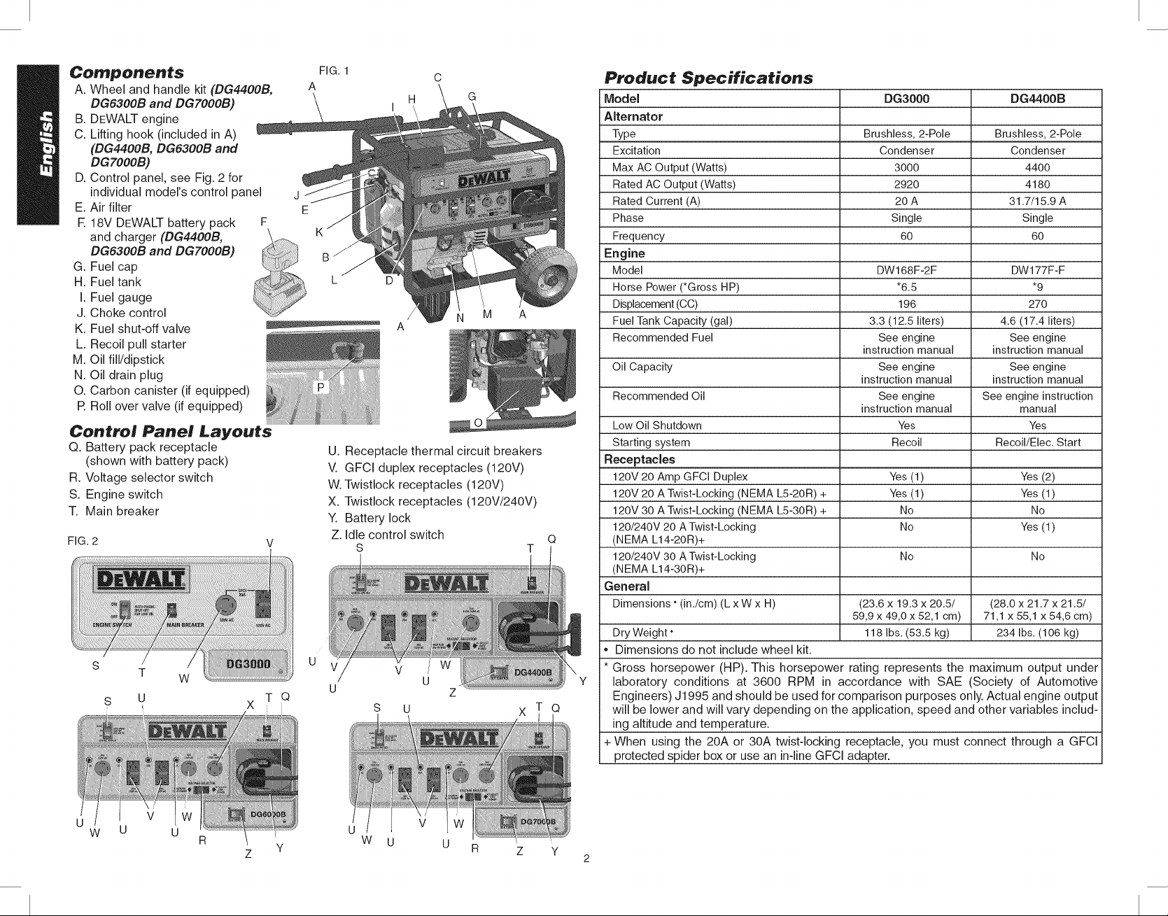
Components
A. Wheel and handle kit (DG44OOB,
DG6300B and DGTOOOB)
B. DEWALT engine
C. Lifting hook (included in A)
(DG4400B, DG6300B and
DGTOOOB)
D. Control panel, see Fig. 2 for
individual model's control panel
E. Air filter
R 18V DEWALT battery pack F
and charger (DG4400B,
DG6300B and DGTOOOB)
G. Fuel cap
H. Fuel tank
I. Fuel gauge
J. Choke control
K. Fuel shut-off valve
L. Recoil pull starter
M. Oil fill/dipstick
N. Oil drain plug
O. Carbon canister (if equipped)
R Roll over valve (if equipped)
Control Panel Layouts
Q. Battery pack receptacle
(shown with battery pack)
R. Voltage selector switch
S. Engine switch
T. Main breaker
FIG. 2
T W
S U X T Q
FIG. 1
A
J
E
C
A
U. Receptacle thermal circuit breakers
V. GFCI duplex receptacles (120V)
W. Twistlock receptacles (120V)
X. Twistlock receptacles (120V/240V
Y. Battery lock
Z. Idle control switch
S
v iw
u
z
Product Specifications
Model
Alternator
Type
Excitation
Max ACOutput (Watts)
Rated AC Output(Watts)
Rated Current (A)
Phase
Frequency
Engine
Model
Horse Power(*Gross HP)
M
Displacement(CC)
FuelTank Capacity (gal)
Recommended Fuel
Oil Capacity See engine See engine
Recommended Oil See engine See engine instruction
Low Oil Shutdown Yes Yes
Starting system Recoil Recoil/Elec. Start
Receptacles
12ov 20 Amp GFCI Duplex Yes (1) Yes (2)
120V 20 A Twist-Locking (NEMA L5-20R) + Yes (1) Yes (1)
120V 30 A Twist-Locking (NEMA L5-30R) + No No
Q
T Q
X
120/240V 20 A Twist-Locking No Yes (1)
(NEMA L14-20R)+
120/240V 30 A Twist-Locking No No
(NEMA L14-30R)+
General
Dimensions • (in./cm) (L x W x H) (23.6 x 19.3 x 20.5/ (28.0 x 21.7 x 21.5/
Dry Weight" 118 Ibs. (53.5 kg) 234 Ibs. (106 kg)
i" Dimensions do not include wheel kit.
i* Gross horsepower (HP). This horsepower rating represents the maximum output under
laboratory conditions at 3600 RPM in accordance with SAE (Society of Automotive
Engineers) J1995 and should be used for comparison purposes only. Actual engine output
will be lower and will vary depending on the application, speed and other variables includ-
ing altitude and temperature.
i+ When using the 20A or 30A twist-locking receptacle, you must connect through a GFCI
protected spider box or use an in-line GFCI adapter.
DG3000 DG4400B
Brushless, 2-Pole Brushless, 2-Pole
Condenser Condenser
3000 4400
2920 4180
20 A 31.7/15.9 A
Single Single
60 60
DW168F-2F DW177F-F
"6.5 *9
196 270
3.3 (12,5 liters) 4.6 (17,4 liters)
See engine See engine
instruction manual instruction manual
instruction manual instruction manual
instruction manual manual
59,9 x 49,0 x 52,1 cm) 71,1 x 55,1 x 54,6 cm)
W U U
R
Y
Z
W U
Page 3
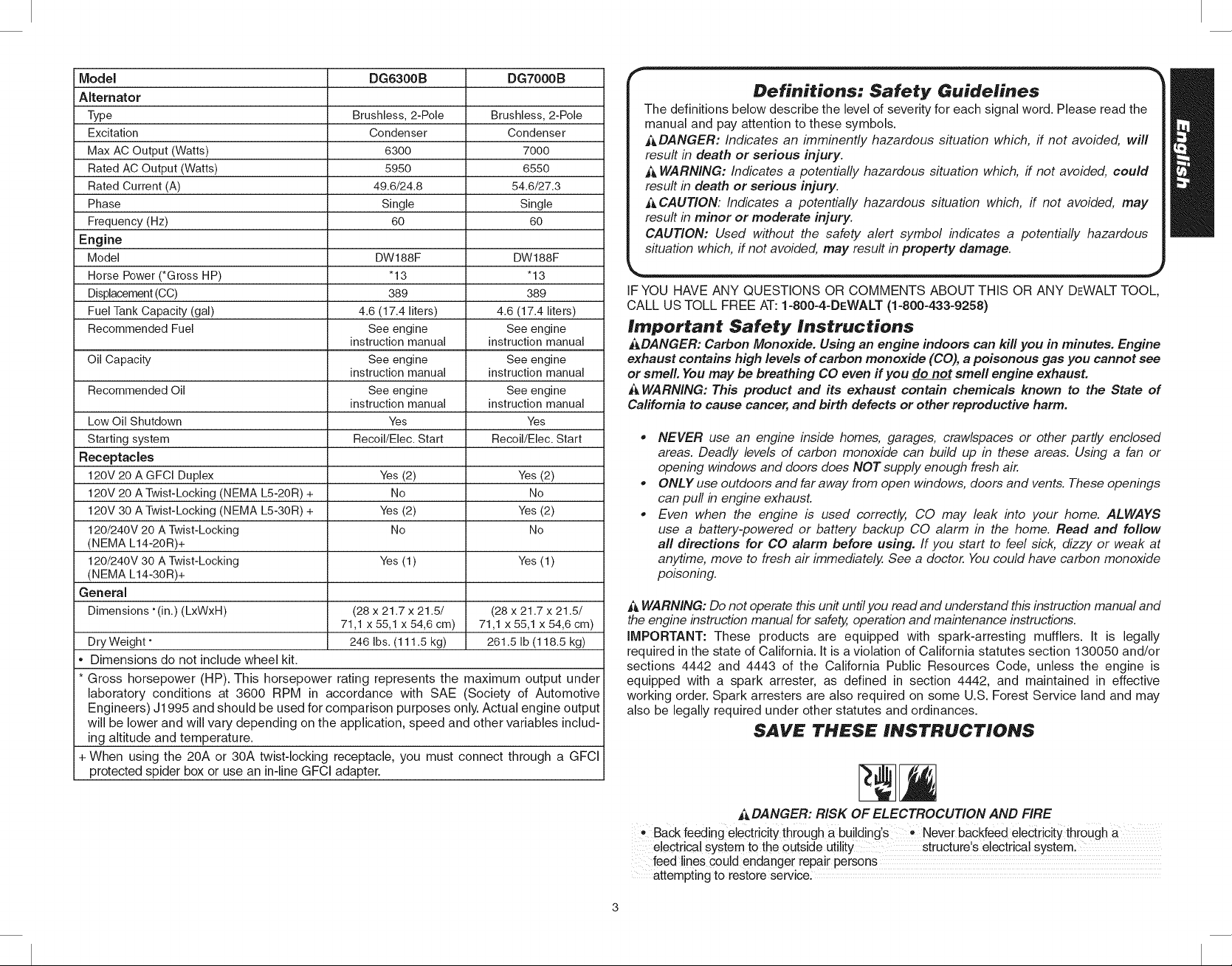
Model DG6300B DG7000 B
Alternator
Type Brushless, 2-Pole Brushless, 2-Pole
Excitation Condenser Condenser
Max AC Output (Watts) 6300 7000
Rated AC Output (Watts) 5950 6550
Rated Current (A) 49.6/24.8 54.6/27.3
Phase Single Single
Frequency (Hz) 60 60
Engine
Model DW188F DW188F
Horse Power (*Gross HP) "13 "13
Displacement (CC) 389 389
Fuel Tank Capacity (gal) 4.6 (17.4 liters) 4.6 (17.4 liters)
Recommended Fuel See engine See engine
instruction manual instruction manual
Oil Capacity See engine See engine
instruction manual instruction manual
Recommended Oil See engine See engine
instruction manual instruction manual
Low Oil Shutdown Yes Yes
Starting system Recoil/Elec. Start Recoil/Elec. Start
Receptacles
120V 20 A GFCI Duplex Yes (2) Yes (2)
120V 20 A Twist-Locking (NEMA L5-20R) + No No
120V 30 A Twist-Locking (NEMA LS-30R) + Yes (2) Yes (2)
120/240V 20 A Twist-Locking No No
(NEMA L14-20R)+
120/240V 30 A Twist-Locking Yes (1) Yes (1)
(NEMA L14-30R)+
General
Dimensions "(in.) (LxWxH) (28 x 21.7 x 21.5/ (28 x 21.7 x 21.5/
71,1 x 55,1 x 54,6 cm) 71,1 x 55,1 x 54,6 cm)
Dry Weight" 246 Ibs. (111.5 kg) 261.5 Ib (118.5 kg)
, Dimensions do not include wheel kit.
* Gross horsepower (HP). This horsepower rating represents the maximum output under
laboratory conditions at 3600 RPM in accordance with SAE (Society of Automotive
Engineers) J1995 and should be used for comparison purposes only. Actual engine output
will be lower and will vary depending on the application, speed and other variables includ-
ing altitude and temperature.
+ When using the 20A or 30A twist-locking receptacle, you must connect through a GFCI
protected spider box or use an in-line GFCI adapter.
Definitions: Safety Guidelines
|The definitions below describe the level of severity for each signal word. Please read the
|manual and pay attention to these symbols.
|ADANGER: Indicates an imminently hazardous situation which, if not avoided, will
|result in death or serious injury.
|_ WARNING: Indicates a potentially hazardous situation which, if not avoided, could
|result in death or serious injury.
| A CAUTION: Indicates a potentially hazardous situation which, if not avoided, may
|result in minor or moderate injury.
|CAUTION: Used without the safety alert symbol indicates a potentially hazardous
_uation which, if not avoided, may result in property damage.
IF YOU HAVE ANY QUESTIONS OR COMMENTS ABOUT THIS OR ANY DEWALTTOOL,
CALL US TOLL FREE AT: I=800=4=DEWALT (1=800=433-9258)
Irnportant Safety Instructions
t&DANGER: Carbon Monoxide. Using an engine indoors can kill you in minutes. Engine
exhaust contains high levels of carbon monoxide (CO), a poisonous gas you cannot see
or smell. You may be breathing CO even if you do not smell engine exhausL
i_ WARNING: This product and its exhaust contain chemicals known to the State of
California to cause cancer, and birth defects or other reproductive harm.
NEVER use an engine inside homes, garages, crawlspaces or other partly enclosed
areas. Deadly levels of carbon monoxide can build up in these areas. Using a fan or
opening windows and doors does NOT supply enough fresh air.
, ONLY use outdoors and far away from open windows, doors and vents. These openings
can pull in engine exhaust.
, Even when the engine is used correctly, CO may leak into your home. ALWAYS
use a battery-powered or battery backup CO alarm in the home. Read and follow
aft directions for CO alarm before using. If you start to feel sick, dizzy or weak at
anytime, move to fresh air immediately, See a doctor. Youcould have carbon monoxide
poisoning.
WARNING: Do not operate this unit until you read and understand thb instruction manual and
the engine instruction manual for safety, operation and maintenance instructions.
IMPORTANT: These products are equipped with spark-arresting mufflers. It is legally
required in the state of California. It is a violation of California statutes section 130050 and/or
sections 4442 and 4443 of the California Public Resources Code, unless the engine is
equipped with a spark arrester, as defined in section 4442, and maintained in effective
working order. Spark arresters are also required on some U.S. Forest Service land and may
also be legally required under other statutes and ordinances.
SAVE THESE INSTRUCTIONS
DANGER: RISK OF ELECTROCUTION AND FIRE
Back feeding electricity thi0ugh a building's * Never backfeed electricity through a
electrical system to the 0utside structure's electrical systeml
!jnes could endanger repa!r persons
attempting to restore service.
Page 4
• Attempting to connect to the incoming utility
service could result in electrocution.
• Restoration of electrical service while the
generator is connected to the incoming utility
could result in a fire or serious damage ifa
double throw transfer switch is not installed.
• Failure to use a double throw transfer switch
when connecting to a structure's electrical
system can damage appliances and WILL
VOID the manufacturer's warranty.
" Water CanConductelectricity! Water Which ,Operate generator in a clean, dry, Well
comes in contact with electrically charged ventilated area. Make sure,hands are dry
components can transmit electricity to before touching unitl
the frame and other surfaces; resulting in
electrical shock to anyone contacting them.
• Contact with worn or damaged extension . Inspect extension cords before use and
cords could result in electrocution, replace with new cord if required.
useof undersize e_ension c0rd(s)Could ,, use proper Size (wiregauge) extension
result in Overheating Ofthe wires 0r attached cord(s) forapplication; see Useof
items, resulting in fire. Extension Cords under Assembly
• Use of ungrounded extension cord(s) could , Always use an extension cord(s) having
prevent operation of circuit breakers and a grounding wire with an appropriate
result in electrical shock, grounding plug. DO NOT use an
Accidenta! leakage 0f electrical Current Place generator Onlow Conductivity Surface
could charge conductive surfaces in contact such as a concrete slab. ALWAYS Operate
with the generat0 r generator a minimum of 6 (1.8 m) from any
• Exceeding the load capacity of the
generator by attaching too many items,
or items with very high load ratings to it
could result in overheating of some items
or their attachment wiring resulting in fire
or electrical shock.
o Attempting tOuse the Unit When it Do not operate generat0r with mechanical
has been damaged or when it is not or electrical problem, Contact a DEWALT
functioning normally c0uld iesu!t in fireor fact0ry Service Center oi a DEWALT
electrocution, authorized service center.
• Removal of guarding could expose ,, Do not operate generator with protective
electrically charged components and guarding removed.
result in electrocution.
'Unattended 0potation of this product. Always remain in attendance With the
could result in personal injury or engine when it is operating.
property damage_To reduce the risk of
fire, do not allow the engine to operate
unattended.
,, To connect to a structure's electrical system
in a safe manner, always have a double-
throw transfer switch installed by a qualified
electrician and incompliance with local
ordinances. (When installing a double-throw
transfer switch, a minimum of 10 gauge
wiring must be used.)
ungrounded plug.
conductive surface.
• See Operating Heavy Loads under
Operation. Make sure that the summation
of electrical loads for all attachments does
not exceed the load rating of the generator.
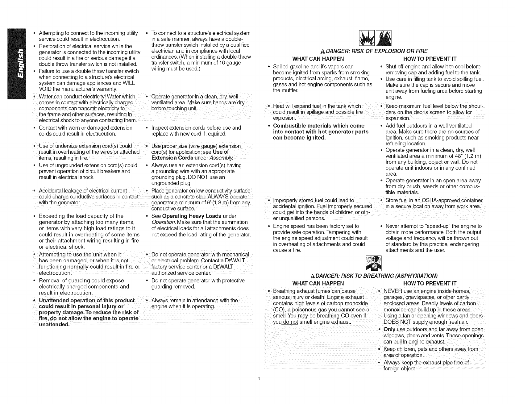
_DANGER: RISK OF EXPLOSION OR FIRE
WHAT CAN HAPPEN HOWTO PREVENT IT
Spilled gasoline and it's vapors can • Shut off engine and allow itto cool before
become ignited from sparks from smoking removing cap and adding fuel to the tank.
products, electrical arcing, exhaust, flame, • Use care in filling tank to avoid spilling fuel.
gases and hot engine components such as Make sure the cap is secure and move
the muffler, unit away from fueling area before starting
engine.
, Heat will expand fue! in the tank Which ,, Keep maximum fue! !eve!be!ow the Sh0ul-
could result in spillage and possible fire ders on the debris screen to al ow for
explosionl expansionl
• Combustible materials which come • Add fuel outdoors in a well ventilated
into contact with hot generator parts area. Make sure there are no sources of
can become ignited, ignition, such as smoking products near
refueling location.
• Operate generator in a clean, dry, well
ventilated area a minimum of 48" (1.2 m)
from any building, object or wall. Do not
operate unit indoors or inany confined
area.
,, Operate generator in an open area away
from dry brush, weeds or other combus-
tible materials.
,, improperlY stored fuel Could lead to ,, Store fuel in an OSHA-approved Container,
accidental ignition. Fuel improperly secured in a Secure location away from work area.
cou!d get into the hands ofchildren or oth-
er unqualified persons.
Engine speed has been factory set to • Never attempt to "speed-up" the engine to
provide safe operation. Tampering with obtain more performance. Both the output
the engine speed adjustment could result voltage and frequency will be thrown out
in overheating of attachments and could of standard by this practice, endangering
cause a fire. attachments and the user.
ADANGER: RISK TO BREATHING (ASPHYXIATION)
WHAT CAN HAPPEN HOWTO PREVENT iT
• Breathing exhaust fumes can cause • NEVER use an engine inside homes.
serious injury or death! Engine exhaust garages, crawlspaces, or other partly
contains high levels of carbon monoxide enclosed areas. Deadly levels of carbon
(CO), a poisonous gas you cannot see or monoxide can build up in these areas.
smell. You may be breathing CO even if Using a fan or opening windows and doors
you do not smell engine exhaust. DOES NOT supply enough fresh air.
- Only use outdoors and far away from open
windows, doors and vents. These openings
can pull inengine exhaust.
= Keepchildren, pets and others away from
area of operation.
- Always keep the exhaust pipe free of
foreign object
Page 5
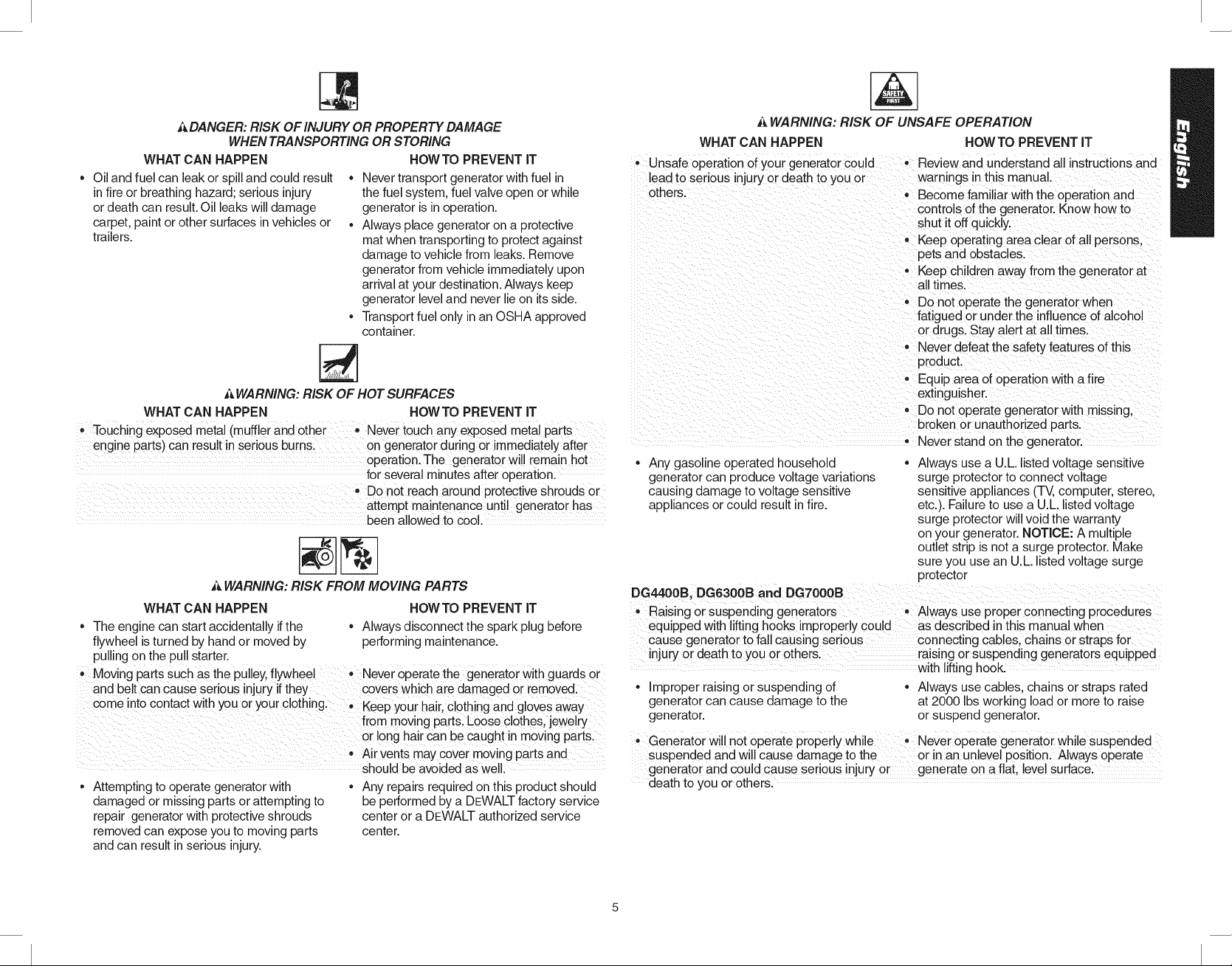
ADANGER:RISK OF INJURY OR PROPERTY DAMAGE
WHEN TRANSPORTING OR STORING
WHATCAN HAPPEN
• Oil and fuel can leak or spill and could result
in fire or breathing hazard; serious injury
or death can result.Oil leaks will damage
carpet, paint or other surfaces in vehicles or
trailers.
AWARNING: RISK OF HOT SURFACES
WHAT CAN HAPPEN HOWTO PREVENT IT
Touching exposed metal (muffler and 0ther Never touch any exposed meta! paits
engine parts) can result in serious burns: on generator during orimmediately after
................................................ attempt maintenance until generator has
_'kWARNING: RISK FROM MOVING PARTS
WHAT CAN HAPPEN HOWTO PREVENT IT
• The engine can start accidentally ifthe • Always disconnect the spark plug before
flywheel is turned by hand or moved by performing maintenance.
pulling on the pull starter•
,, Moving paits Such as the pulley, flywheel Never operate the generator Withguards or
andbelt CanCause serious njury ifthey covers Which are damaged or removed:
COme nto contact wth you or your cloth ng , Kee ourhair, clothin and Iovesawa
• Attempting to operate generator with
damaged or missing parts or attempting to
repair generator with protective shrouds
removed can expose you to moving parts
and can result inserious injury.
• Never transport generator with fuel in
the fuel system, fuel valve open or while
generator is in operation.
• Always place generator on a protective
mat when transporting to protect against
damage to vehicle from leaks. Remove
generator from vehicle immediately upon
arrival at your destination. Always keep
generator level and never lie on its side.
• Transport fuel only inan OSHA approved
container.
* Do n0t reach around protective Shrouds 0r
• py g g Y
from moving Part& Loose clothes, jewe!ry
or !ong hair Can be caught in moving parts.
Air vents may Covermoving partSand
should be avoided as well.
• Any repairs required on this product should
be performed by a DEWALTfactory service
center or a DEWALT authorized service
center.
HOWTO PREVENT IT
0perati0n, The generatorwi!! remain hot
for several minutes after operation.
been allowed to cool.
A WARNING: RISK OF UNSAFE OPERATION
WHAT CAN HAPPEN HOWTOPREVENTIT
- Unsafe operation of your generator could
lead to serious injury or death to you or
others.
• Any gasoline operated household • Always use a U.L listed voltage sensitive
generator can produce voltage variations surge protector to connect voltage
causing damage to voltage sensitive sensitive appliances (TV, computer, stereo.
appliances or could result in fire. etc.). Failure to use a U.L listed voltage
DG4400B, DG6300B and DGT000B
Raising or suspending generators ,, Always use proper connecting procedures
equipped with lifting hooks improperly could as described in this manual when
cause generator to fall causing serious connecting cables, chains or straps for
injury or death to you or others, raising or suspending generators equipped
• Improper raising or suspending of ,, Always use cables, chains or straps rated
generator can cause damage to the at 2000 Ibs working load or more to raise
generator, or suspend generator.
,, Generator wi!lnot operate proPerly while ,, Never oPerate generat0i while suspended
suspended and will cause damage to the or in an unlevel position. Always operate
generator and could cause serious injury generate on a flat, level surfacel
death to you or others.
• Review and understand all instructions and
warnings in this manual.
- Become familiar with the operation and
controls of the generator. Know how to
shut it off quickly.
• Keep ope rating area clear of all persons.
pets and obstacles.
- Keep children away from the generator at
all times.
,, Do not operate the generator when
fatigued or under the influence of alcohol
or drugs. Stay alert at all times.
• Never defeat the safety features of this
product.
,, Equip area of operation with a fire
extinguisher.
- Do not operate generator with missing,
broken or unauthorized parts.
,, Never stand on the generator.
surge protector will void the warranty
on your generator. NOTICE: A multiple
outlet strip is not a surge protector. Make
sure you use an U.L. listed voltage surge
protector
with lifting hook.
Page 6
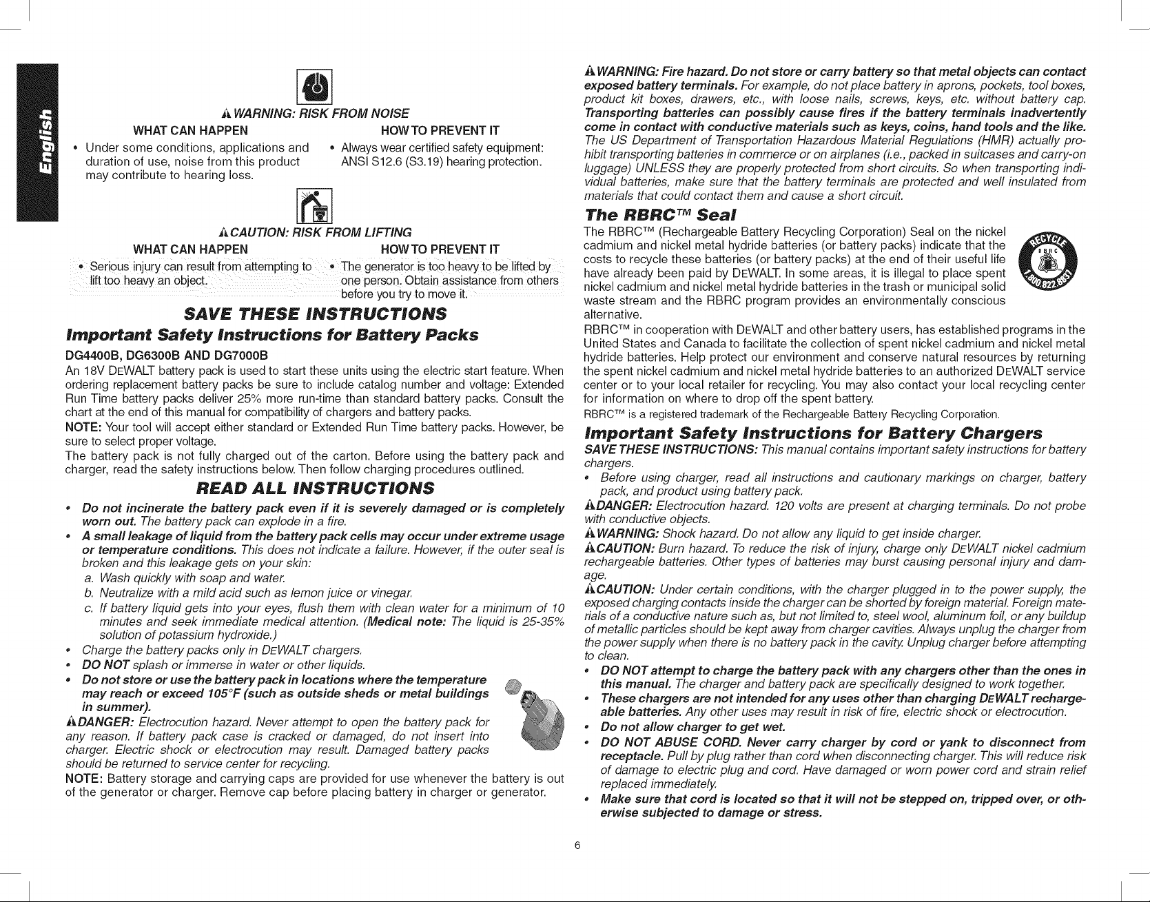
WARNING: RISK FROM NOISE
WHAT CAN HAPPEN HOWTO PREVENT IT
• Under some conditions, applications and • Always wear certified safety equipment:
duration of use, noise from this product ANSI S12.6 (S3.19) hearing protection.
may contribute to hearing loss.
_ CAUTION: RISK FROM LIFTING
WHAT CAN HAPPEN HOWTO PREVENT iT
• Serious injury can resu!t from attempting tO • The generator is tOOheavy t0be lifted by
lift too heavy an object, one person. Obtain assistance fr0m 0thers
before you try to move it:
SAVE THESE INSTRUCTIONS
Important Safety Instructions for Battery Packs
DG4400B, DG6300B AND DGT000B
An 18V DEWALT battery pack is used to start these units using the electric start feature. When
ordering replacement battery packs be sure to include catalog number and voltage: Extended
Run Time battery packs deliver 25% more run-time than standard battery packs. Consult the
chart at the end of this manual for compatibility of chargers and battery packs.
NOTE: Your tool will accept either standard or Extended Run Time battery packs. However, be
sure to select proper voltage.
The battery pack is not fully charged out of the carton. Before using the battery pack and
charger, read the safety instructions below. Then follow charging procedures outlined.
READ A££ INSTRUCTIONS
* Do not incinerate the battery pack even if it is severely damaged or is completely
worn out. The battery pack can explode in a fire.
* A smafl leakage of liquid from the battery pack cells may occur under extreme usage
or temperature conditions. This does not indicate a failure. However, ff the outer seal is
broken and this leakage gets on your skin:
a. Wash quickly with soap and water.
b. Neutralize with a mild acid such as lemon juice or vinegar.
c. If battery liquid gets into your eyes, flush them with clean water for a minimum of 10
minutes and seek immediate medical attention. (Medical note: The liquid is 25-35%
solution of potassium hydroxide.)
* Charge the battery packs only in DEWALT chargers.
* DO NOT splash or immerse in water or other liquids.
* Do not store or use the batterypack in locations where the temperature
may reach or exceed I05°F (such as outside sheds or metal buildings
in summer).
ADANGER: Electrocution hazard. Never attempt to open the battery pack for
any reason. If battery pack case is cracked or damaged, do not insert into
charger. Electric shock or electrocution may result. Damaged battery packs
should be returned to service center for recycling.
NOTE: Battery storage and carrying caps are provided for use whenever the battery is out
of the generator or charger. Remove cap before placing battery in charger or generator.
_, WARNING: Fire hazard. Do not store or carry battery so that metal objects can contact
exposed battery terminals. For example, do not place battery in aprons, pockets, tool boxes,
product kit boxes, drawers, etc., with loose nails, screws, keys, etc. without battery cap.
Transporting batteries can possibly cause fires if the battery terminals inadvertently
come in contact with conductive materials such as keys, coins, hand tools and the like.
The US Department of Transportation Hazardous Material Regulations (HMR) actually pro-
hibit transporting batteries in commerce or on airplanes (i.e., packed in suitcases and carry-on
luggage) UNLESS they are properly protected from short circuits. So when transporting indi-
vidual batteries, make sure that the battery terminals are protected and weft insulated from
materials that could contact them and cause a short circuit.
The RBRC TM Seal
The RBRC TM (Rechargeable Battery Recycling Corporation) Seal on the nickel
cadmium and nickel metal hydride batteries (or battery packs) indicate that the
costs to recycle these batteries (or battery packs) at the end of their useful life
have already been paid by DEWALT. In some areas, it is illegal to place spent
nickel cadmium and nickel metal hydride batteries in the trash or municipal solid
waste stream and the RBRC program provides an environmentally conscious
alternative.
RBRC TM in cooperation with DEWALT and other battery users, has established programs in the
United States and Canada to facilitate the collection of spent nickel cadmium and nickel metal
hydride batteries. Help protect our environment and conserve natural resources by returning
the spent nickel cadmium and nickel metal hydride batteries to an authorized DEWALT service
center or to your local retailer for recycling. You may also contact your local recycling center
for information on where to drop off the spent battery.
RBRCTM isa registeredtrademark of the RechargeableBatteryRecyclingCorporation.
Irnportant Safety Instructions for Battery Chargers
SAVE THESE INSTRUCTIONS: This manual contains important safety instructions for battery
chargers.
* Before using charger, read aft instructions and cautionary markings on charger, battery
pack, and product using battery pack.
ADANGER: Electrocution hazard. 120 volts are present at charging terminals. Do not probe
with conductive objects.
_, WARNING: Shock hazard. Do not allow any fiquid to get inside charger.
_CAUTION: Burn hazard. To reduce the risk of injury, charge only DEWALT nickel cadmium
rechargeable batteries. Other types of batteries may burst causing personal injury and dam-
age.
_,CAUTION: Under certain conditions, with the charger plugged in to the power supply, the
exposed charging contacts inside the charger can be shorted by foreign material Foreign mate-
rials of a conductive nature such as, but not limited to, steel wool, aluminum foil, or any buildup
of metallic particles should be kept away from charger cavities. Always unplug the charger from
the power supply when there b no battery pack in the cavity. Unplug charger before attempting
to clean.
* DO NOTattempt to charge the battery pack with any chargers other than the ones in
this manual. The charger and battery pack are specifically designed to work together.
* These chargers are not intended for any uses other than charging DEWALT recharge-
able batteries. Any other uses may result in risk of fire, electric shock or electrocution.
* Do not allow charger to get wet.
* DO NOT ABUSE CORD. Never carry charger by cord or yank to disconnect from
receptacle. Puff by plug rather than cord when disconnecting charger. This will reduce risk
of damage to electric plug and cord. Have damaged or worn power cord and strain relief
replaced immediately,
* Make sure that cord is located so that it will not be stepped on, tripped over, or oth-
erwise subjected to damage or stress.
Page 7
• Do not use an extension cord unless it is absolutely necessary. Use of improper
extension cord could result in risk of fire, electric shock, or electrocution.
• An extension cord must have adequate wire size (AWG orAmerican Wire Gauge) for
safety. The smaller the gauge number of the wire, the greater the capacity of the cable,
that is 16 gauge has more capacity than 18 gauge. When using more than one extension to
make up the total length, be sure each individual extension contains at least the minimum
wire size. If an extension cord is to be used outdoors it must be marked with the suffix
W-A or W following the cord type designation. For example - SJTW-A to indicate it is
acceptable for outdoor use.
Recommended Minimum Wire Size for Extension Cords
Total Length of Cord
25 ft. 50 ft. 75 ft. 100 ft. 125 ft. 150 ft. 175 ft.
7.6 m 15.2 m 22.9 m 30.5 m 38.1 m 45.7 m 53.3 m
Wire Size AWG
18 18 16 16 14 14 12
• Do not place any object on top of charger or place the charger on a soft surface
that might block the ventilation slots and result in excessive internal heat. Place the
charger in a position away from any heat source. The charger is ventilated through slots in
the top and the bottom of the housing.
• Do not operate charger with damaged cord or plug -- have them replaced immedi-
ately.
• Do not operate charger if it has received a sharp blow, been dropped, or otherwise
damaged in any way. Take it to an authorized service center.
• Do not disassemble charger; take it to an authorized service center when service or
repair is required. Incorrect reassembly may result in a risk of electric shock, electrocu-
tion or fire.
• Disconnect the charger from the outlet before attempting any cleaning. This will
reduce the risk of electric shock. Removing the battery pack will not reduce this risk.
• NEVER attempt to connect 2 chargers together.
• The charger is designed to operate on standard household electrical power (120
Volts). Do not attempt to use it on any other voltage. This does not apply to the
vehicular charger.
SAVE THESE INSTRUCTIONS FOR FUTURE USE
Charging Procedure
DG4400B, DG6300B AND DGT000B
A DANGER: Electrocution hazard. 120 volts are present at charging terminals. Do not probe
withconductive objects.
1. Plug the charger into an appropriate outlet before inserting battery
pack.
2. Remove the caps from the battery pack and insert battery pack
into the charger. The red (charging) light will blink continuously
indicating that the charging process has started.
3. The completion of charge will be indicated by the red light
remaining ON continuously. The pack is fully charged and may
be used at this time or left in the charger.
Using Automatic Tune-Up TM Mode
DG4400B, DG6300B AND DGT000B
The automaticTune-Up TM Mode equalizes or balances the individual cells in the battery pack
allowing it to function at peak capacity. Battery packs should be tuned up weekly or after
10 charge/discharge cycles or whenever the pack no longer delivers the same amount of
work. To use the Automatic Tune-Up TM, place the battery pack in the charger and leave it
for at least 8 hours.
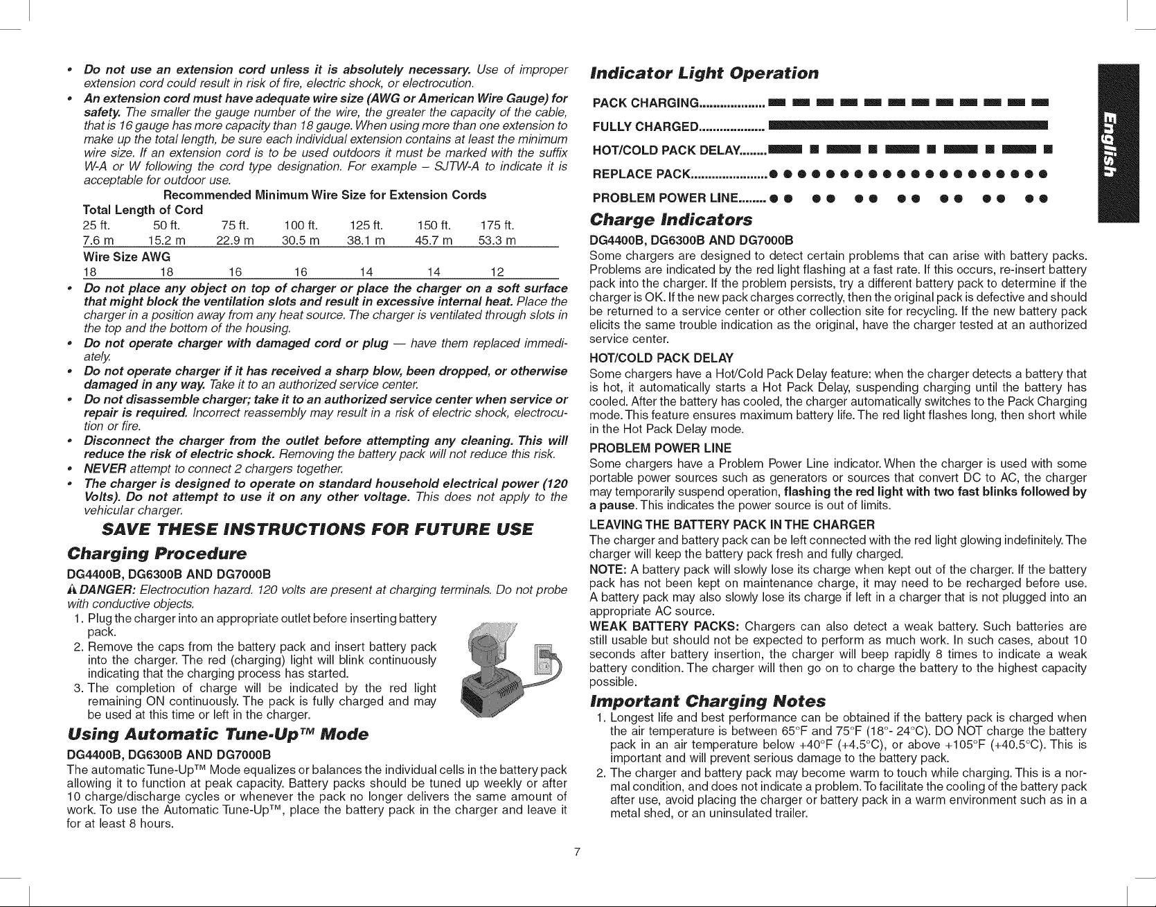
Indicator Light Operation
PACK CHARGING ................... === === === === === === =m =m =m =m =m ===
FULLY CHARGED ...................
HOT/COLD PACK DELAY........ _ [] _ [] _ [] _ [] _ []
REPLACE PACK ...................... ®e®®®o®o®®o®®o®®®e®®
PROBLEM POWER LiNE ........ ® ® ® • ® ® ® ® O ® O ® ® ®
Charge Indicators
DG4400B, DG6300B AND DG7000B
Some chargers are designed to detect certain problems that can arise with battery packs.
Problems are indicated by the red light flashing at a fast rate. if this occurs, re-insert battery
pack into the charger, if the problem persists, try a different battery pack to determine if the
charger is OK. if the new pack charges correctly, then the original pack is defective and should
be returned to a service center or other collection site for recycling, if the new battery pack
elicits the same trouble indication as the original, have the charger tested at an authorized
service center.
HOT/COLD PACK DELAY
Some chargers have a Hot/Cold Pack Delay feature: when the charger detects a battery that
is hot, it automatically starts a Hot Pack Delay, suspending charging until the battery has
cooled. After the battery has cooled, the charger automatically switches to the Pack Charging
mode. This feature ensures maximum battery life.The red light flashes long, then short while
in the Hot Pack Delay mode.
PROBLEM POWER LINE
Some chargers have a Problem Power Line indicator. When the charger is used with some
portable power sources such as generators or sources that convert DC to AC, the charger
may temporarily suspend operation, flashing the red light with two fast blinks followed by
a pause. This indicates the power source is out of limits.
LEAVING THE BATTERY PACK IN THE CHARGER
The charger and battery pack can be left connected with the red light glowing indefinitely. The
charger will keep the battery pack fresh and fully charged.
NOTE: A battery pack will slowly lose its charge when kept out of the charger, if the battery
pack has not been kept on maintenance charge, it may need to be recharged before use.
A battery pack may also slowly lose its charge if left in a charger that is not plugged into an
appropriate AC source.
WEAK BATTERY PACKS: Chargers can also detect a weak battery. Such batteries are
still usable but should not be expected to perform as much work. In such cases, about 10
seconds after battery insertion, the charger will beep rapidly 8 times to indicate a weak
battery condition. The charger will then go on to charge the battery to the highest capacity
possible.
Important Charging Notes
1. Longest life and best performance can be obtained if the battery pack is charged when
the air temperature is between 65°F and 75°F (18°- 24°C). DO NOT charge the battery
pack in an air temperature below +40°F (+4.5°C), or above +105°F (+40.5°C). This is
important and will prevent serious damage to the battery pack.
2. The charger and battery pack may become warm to touch while charging. This is a nor-
mal condition, and does not indicate a problem. To facilitate the cooling of the battery pack
after use, avoid placing the charger or battery pack in a warm environment such as in a
metal shed, or an uninsulated trailer.
Page 8
3.Ifthebatterypackdoesnotchargeproperly:
a.Checkcurrentatreceptaclebyplugginginalamporotherappliance
b.Checktoseeifreceptacleisconnectedtoa lightswitchwhichturnspoweroffwhen
youturnoutthelights.
c.Movechargerandbatterypacktoalocationwherethesurroundingairtemperatureis
approximately65°F-75°F(18°-24°C).
d.Ifchargingproblemspersist,takethetool,batterypackandchargertoyourlocal
servicecenter.
4.Thebatterypackshouldberechargedwhenitfailstoproducesufficientpoweronjobs
whichwereeasilydonepreviously.DONOTCONTINUEtouseundertheseconditions.
Followthechargingprocedure.Youmayalsochargeapartiallyusedpackwheneveryou
desirewithnoadverseaffectonthebatterypack.
5.Undercertainconditions,withthechargerpluggedintothepowersupply,theexposed
chargingcontactsinsidethechargercanbeshortedbyforeignmaterial.Foreignmaterials
ofaconductivenaturesuchas,butnotlimitedto,steelwool,aluminumfoil,oranybuildup
ofmetallicparticlesshouldbekeptawayfromchargercavities.Alwaysunplugthecharger
fromthepowersupplywhenthereisnobatterypackinthecavity.Unplugchargerbefore
attemptingtoclean.
6.Donotfreezeorimmersechargerinwateroranyotherliquid.
i_,WARNING: Shock hazard. Do not allow any liquid to get inside charger.
A CAUTION: Never attempt to open the battery pack for any reason, ff the plastic housing of
the battery pack breaks or cracks, return to a service center for recycling.
Charging Portable Power Tool Batteries
_ WARNING: Condenser type chargers should not be used with portable generators. Irregular
generator power could cause a condenser type charger to fail. DEWALT has produced con-
denser type chargers in the past. (DW9104 and DW9106). ff you have any questions regard-
ing the use of a DEWALT Charger with a generator, please call 1-800-4-DEWALT.
NOTE: Other battery charger manufacturers have and still produce condenser type chargers.
Please contact manufacturer to see if it is safe to use chargers with portable generators.
ASSEMBLY
Grounding the Generator
Agrounding lug (VV)is supplied withthe generator for use when
required by local electrical ordinances. Refer to article 250 of
the National Electrical Code to clarify any needed grounding
information. Your local electric company or a certified electri-
cian should be able to help you with this information.
NOTE: Your engine is already grounded to the frame by a
grounding strap.
Use of Extension Cords
_, WARNING: Use only grounded extension cords. Use only three wire or double-insulated
power tools.
Only use grounded extension cords that are rated for outdoor use and equipment with a third-
wire ground. When using the 20A or 30A twist-locking receptacle, you must connect through
a GFCI protected spider box or use an in-line GFCI adapter.
When a long extension cord is used to connect an appliance or tool to the generator, a volt-
age drop occurs. The longer the cord, the greater the voltage drop. This results in less voltage
being supplied to the appliance or tool and increases the amount of current (amp) draw or
reduces performance. A heavier cord with a larger wire size will reduce the voltage drop. Be
sure to choose a cord that will supply enough voltage to operate your tool or appliance. The
tables indicate appropriate gauge for extension cords and the voltage drop caused by the use
of extension cords, given different electrical loads.
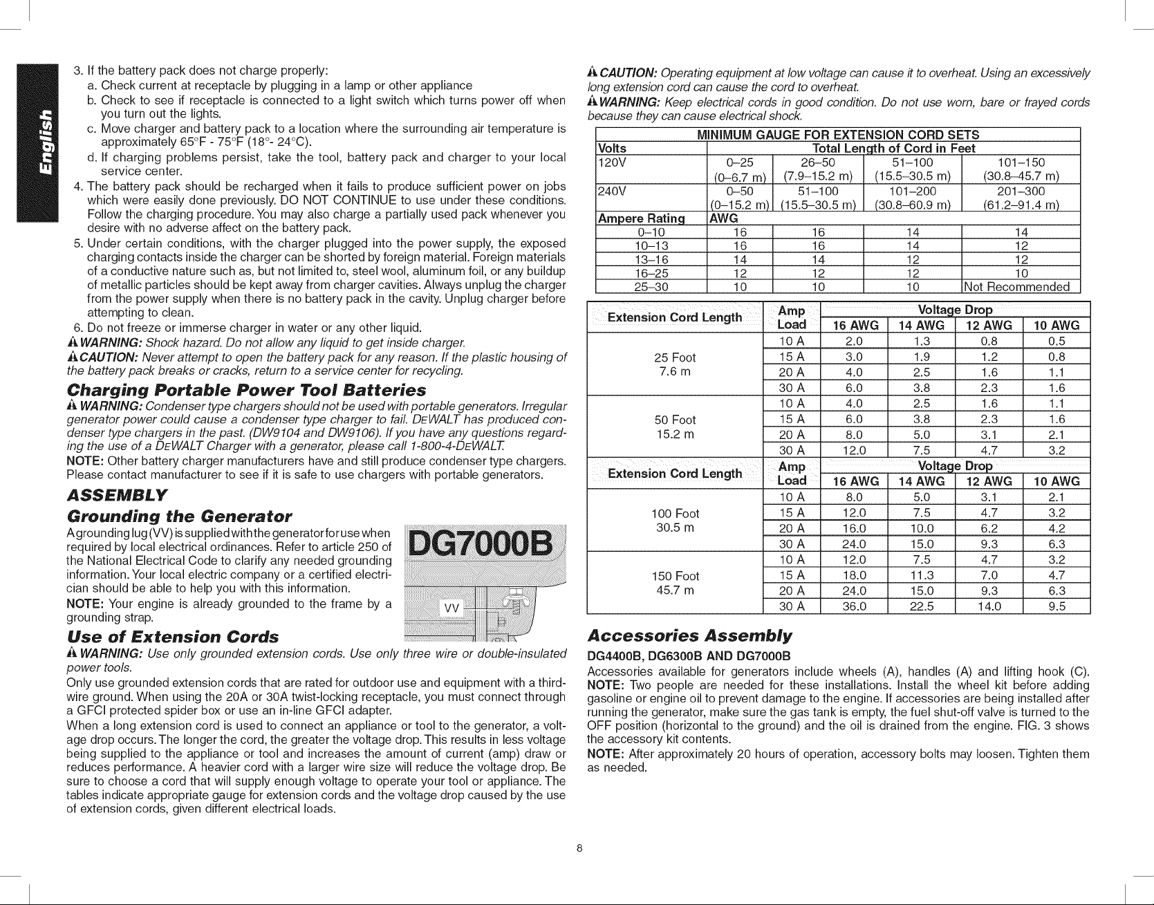
_J,CAUTION: Operating equipment at low voltage can cause # to overheat. Using an excessively
long extension cord can cause the cord to overheat.
WARNING: Keep electrical cords in good condition. Do not use worn, bare or frayed cords
because they can cause electrical shock.
MINIMUM GAUGE FOR EXTENSION CORD SETS
Volts
120V
240V
Ampere Rating
0-10
10-13
13-16
16-25
25-30
Extension Cord Length I LAo_p ' Voltage Drop
25 Foot 15 A 3.0
7.6 m 20 A 4.0
50 Foot 15 A 6.0
15.2 m 20 A 8.0
Extension Cord Length Amp Voltage Drop
100 Foot 15 A 12.0
30.5 m 20 A 16.0
150 Foot 15 A 18.0
45.7 m 20 A 24.0
0-25
(0-6.7 m)
0-50
(0-15.2 m)
AWG
16
16
14
12
10
Total Length of Cord in Feet
26-50 51-100 101-150
(7.9-15.2 m) (15.5-30.5 m) (30.8-45.7 m)
51-100 101-200 201-300
(15.5-30.5 m) (30.8-60.9 m) (61.2-91.4 m)
16 14
16 14
14 12
12 12
10 10
Not Recommended
14
12
12
10
16AWG14AWG 2AWG 0AWG
10A 2.0
30 A 6.0
10 A 4.0
30 A 12.0
Load 16 AWG 14 AWG 12 AWG 10 AWG
10 A 8.0
30 A 24.0
10 A 12.0
30 A 36.0
1.3
1.9
2.5
3.8
2.5
3.8
5.0
7.5
5.0
7.5
10.0
15.0
7.5
11.3
15.0
22.5
0.8
1.2
1.6
2.3
1.6
2.3
3.1
4.7
3.1
4.7
6.2
9.3
4.7
7.0
9.3
14.0
0.5
0.8
1.1
1.6
1.1
1.6
2.1
3.2
2.1
3.2
4.2
6.3
3.2
4.7
6.3
9.5
Accessories Assembly
DG4400B, DG6300B AND DGT000B
Accessories available for generators include wheels (A), handles (A) and lifting hook (C).
NOTE: Two people are needed for these installations. Install the wheel kit before adding
gasoline or engine oil to prevent damage to the engine. If accessories are being installed after
running the generator, make sure the gas tank is empty, the fuel shut-off valve is turned to the
OFF position (horizontal to the ground) and the oil is drained from the engine. FIG. 3 shows
the accessory kit contents.
NOTE: After approximately 20 hours of operation, accessory bolts may loosen. Tighten them
as needed.
Page 9
LL
JJ
cc
_ KK
GG
FF
AA
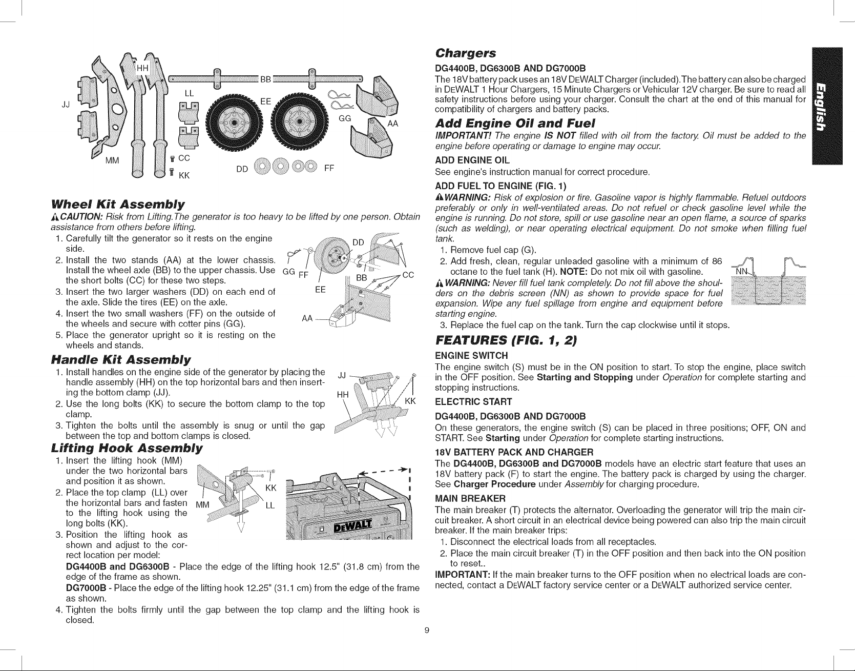
Wheel Kit Assembly
_ CAUTION: Risk from Lifting.The generator is too heavy to be lifted by one person. Obtain
assistance from others before lifting.
1. Carefully tilt the generator so it rests on the engine DD
side. )_ _I_
2. Install the two stands (AA) at the lower chassis. / :_'. --
Install the wheel axle (BB) to the upper chassis. Use GG FF / LI::: ....,-,,-,
the short bolts (CC) for these two steps. / BB._ ....
3. Insert the two larger washers (DD) on each end of EE _<_
the axle. Slide the tires (EE) on the axle.
4. Insert the two small washers (FF)on the outside of
the wheels and secure with cotter pins (GG). AA _ _
5. Place the generator upright so it is resting on the
wheels and stands.
Handle Kit Assembly
1. Install handles on the engine side of the generator by placing the
handle assembly (HH) on the top horizontal bars and then insert-
ing the bottom clamp (JJ).
2. Use the long bolts (KK) to secure the bottom clamp to the top
clamp.
3. Tighten the bolts until the assembly is snug or until the gap
between the top and bottom clamps is closed.
£iff:ing Hook Assembly
1. Insert the lifting hook (MM)
under the two horizontal bars "_
and position it as shown. I
2. Place the top clamp (LL) over I
the horizontal bars and fasten
to the lifting hook using the
long bolts (KK).
3. Position the lifting hook as
shown and adjust to the cor-
rect location per model:
DG4400B and DG6300B - Place the edge of the lifting hook 12.5" (31.8 cm) from the
edge of the frame as shown.
DG7000B - Place the edge of the lifting hook 12.25" (31.1 cm) from the edge of the frame
as shown.
4. Tighten the bolts firmly until the gap between the top clamp and the lifting hook is
closed.
Chargers
DG4400B, DG6300B AND DG7000B
The 18V battery pack uses an 18V DEWALT Charger (included).The battery can also be charged
in DEWALT 1 Hour Chargers, 15 Minute Chargers or Vehicular 12V charger. Be sure to read all
safety instructions before using your charger. Consult the chart at the end of this manual for
compatibility of chargers and battery packs.
Add Engine Oil and Fuel
IMPORTANT! The engine IS NOT filled with oil from the factory. Oil must be added to the
engine before operating or damage to engine may occur.
ADD ENGINE OIL
See engine's instruction manual for correct procedure.
ADD FUELTO ENGINE (FIG. 1)
,&WARNING: Risk of explosion or fire. Gasoline vapor is highly flammable. Refuel outdoors
preferably or only in well-ventilated areas. Do not refuel or check gasoline level while the
engine is running. Do not store, spill or use gasoline near an open flame, a source of sparks
(such as welding), or near operating electrical equipment. Do not smoke when filling fuel
tank.
1. Remove fuel cap (G).
2. Add fresh, clean, regular unleaded gasoline with a minimum of 86
octane to the fuel tank (H). NOTE: Do not mix oil with gasoline.
WARNING: Never fill fuel tank completely. Do not fill above the shoul-
ders on the debris screen (NN) as shown to provide space for fuel
expansion. Wipe any fuel spillage from engine and equipment before
starting engine.
3. Replace the fuel cap on the tank. Turn the cap clockwise until it stops.
FEATURES (FIG. 1{, 2)
ENGINE SWITCH
The engine switch (S) must be in the ON position to start. To stop the engine, place switch
in the OFF position. See Starting and Stopping under Operation for complete starting and
stopping instructions.
ELECTRIC START
DG4400B, DG6300B AND DG7000B
On these generators, the engine switch (S) can be placed in three positions; OFF, ON and
START. See Starting under Operation for complete starting instructions.
18V BATTERY PACK AND CHARGER
The DG4400B, DG6300B and DG7000B models have an electric start feature that uses an
18V battery pack (F) to start the engine. The battery pack is charged by using the charger.
See Charger Procedure under Assembly for charging procedure.
MAIN BREAKER
The main breaker (T) protects the alternator. Overloading the generator will trip the main cir-
cuit breaker. A short circuit in an electrical device being powered can also trip the main circuit
breaker. If the main breaker trips:
1. Disconnect the electrical loads from all receptacles.
2. Place the main circuit breaker (T) in the OFF position and then back into the ON position
to reset..
iMPORTANT: Ifthe main breaker turns to the OFF position when no electrical loads are con-
nected, contact a DEWALT factory service center or a DEWALT authorized service center.
Page 10
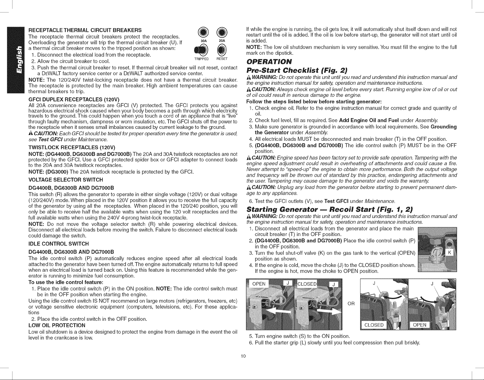
RECEPTACLE THERMAL CIRCUIT BREAKERS @ @
The receptacle thermal circuit breakers protect the receptacles.
Overloading the generator will trip the thermal circuit breaker (U). If 1_,,3°A 2oA
a thermal circuit breaker moves to the tripped position as shown: _ (i'_)'J
1. Disconnect the electrical load from the receptacle.
2. Allow the circuit breaker to cool. TRIPPED RESET
3. Push the thermal circuit breaker to reset. If thermal circuit breaker will not reset, contact
a DEWALT factory service center or a DEWALT authorized service center.
NOTE: The 120/240V twist-locking receptacle does not have a thermal circuit breaker.
The receptacle is protected by the main breaker. High ambient temperatures can cause
thermal breakers to trip.
GFCl DUPLEX RECEPTACLES (120V)
All 20A convenience receptacles are GFCI (V) protected. The GFCI protects you against
hazardous electrical shock caused when your body becomes a path through which electricity
travels to the ground. This could happen when you touch a cord of an appliance that is "live"
through faulty mechanism, dampness or worn insulation, etc. The GFCI shuts off the power to
the receptacle when it senses small imbalances caused by current leakage to the ground.
t&CAUTION: Each GFCI should be tested for proper operation every time the generator is used,
see Test GFCI under Maintenance.
TWISTLOCK RECEPTACLES (120V)
NOTE: (DG4400B, DG6300B and DG7000B) The 20A and 30A twistlock receptacles are not
protected by the GFCI. Use a GFCI protected spider box or GFCI adapter to connect loads
to the 20A and 30A twistlock receptacles.
NOTE: (DG3000) The 20A twistlock receptacle is protected by the GFCI.
VOLTAGE SELECTOR SWITCH
DG4400B, DG6300B AND DG7000B
This switch (R) allows the generator to operate in either single voltage (120V) or dual voltage
(120/240V) mode. When placed in the 120V position it allows you to receive the full capacity
of the generator by using all the receptacles. When placed in the 120/240 position, you will
only be able to receive half the available watts when using the 120 volt receptacles and the
full available watts when using the 240V 4-prong twist-lock receptacle.
NOTE: Do not move the voltage selector switch (R) while powering electrical devices.
Disconnect all electrical loads before moving the switch. Failure to disconnect electrical loads
could damage the switch.
IDLE CONTROL SWITCH
DG4400B, DG6300B AND DG7000B
The idle control switch (P) automatically reduces engine speed after all electrical loads
attached to the generator have been turned off. The engine automatically returns to full speed
when an electrical load is turned back on. Using this feature is recommended while the gen-
erator is running to minimize fuel consumption.
To use the idle control feature:
1. Place the idle control switch (P) in the ON position. NOTE: The idle control switch must
be in the OFF position when starting the engine.
Using the idle control switch IS NOT recommend on large motors (refrigerators, freezers, etc)
or voltage sensitive electronic equipment (computers, televisions, etc). For these applica-
tions
2. Place the idle control switch in the OFF position.
LOW OIL PROTECTION
Low oil shutdown is a device designed to protect the engine from damage in the event the oil
level in the crankcase is low.
If while the engine is running, the oil gets low, it will automatically shut itself down and will not
restart until the oil is added. If the oil is low before start-up, the generator will not start until oil
is added.
NOTE: The low oil shutdown mechanism is very sensitive. You must fill the engine to the full
mark on the dipstick.
OPERATION
PreoStart Checklist (Fig. 2)
_, WARNING: Do not operate this unit until you read and understand this instruction manual and
the engine instruction manual for safe_ operation and maintenance instructions.
A CAUTION: Always check engine oil level before every start. Running engine low of oil or out
of oil could result in serious damage to the engine.
Follow the steps listed below before starting generator:
1. Check engine oil. Refer to the engine instruction manual for correct grade and quantity of
oil.
2. Check fuel level, fill as required. See Add Engine Oil and Fuel under Assembly.
3. Make sure generator is grounded in accordance with local requirements. See Grounding
the Generator under Assembly.
4. All electrical loads MUST be disconnected and main breaker (T) in the OFF position.
5. (DG4400B, DG6300B and DG7000B) The idle control switch (P) MUST be in the OFF
position.
CAUTION: Engine speed has been factory set to provide safe operation. Tampering with the
engine speed adjustment could result in overheating of attachments and could cause a fire.
Never attempt to "speed-up" the engine to obtain more performance. Both the output voltage
and frequency will be thrown out of standard by this practice, endangering attachments and
the user. Tampering may cause damage to the generator and voids the warranty.
ik CAUTION: Unplug any load from the generator before starting to prevent permanent dam-
age to any appliances.
6. Test the GFCI outlets (V), see Test GFCl under Maintenance.
Starting Generator _ Recoil Start (Fig. 1, 2)
WARNING: Do not operate this unit until you read and understand this instruction manual and
the engine instruction manual for safety, operation and maintenance instructions.
1. Disconnect all electrical loads from the generator and place the main
circuit breaker (T) in the OFF position.
2. (DG4400B, DG6300B and DG7000B) Place the idle control switch (P)
in the OFF position.
3. Turn the fuel shut-off valve (K) on the gas tank to the vertical (OPEN)
position as shown.
4. If the engine is cold, move the choke (J) to the CLOSED position shown.
If the engine is hot, move the choke to OPEN position.
OR
5. Turn engine switch (S) to the ON position.
6. Pull the starter grip (L) slowly until you feel compression then pull briskly.
lO
Page 11
NOTE: Do not allow the starter grip to snap back. Return it slowly by hand.
NOTE: If the oil level in the engine is low, the engine will not start. Ifthe engine does not start,
check the oil level and add oil as needed.
NOTE: To ensure maximum oil lubrication, place the generator on a level surface.
7. As the engine warms up, move the choke to the OPEN position.
8. Allow the engine to warm up for five minutes. Then place the main breaker (T) in the ON
position. Connect electrical loads, see Connecting Electrical Loads under Operation.
Starting the Generator _ Electric Start (Fig. 1, 2)
(DG4400B, DG6300B and DGTOOOB)
WARNING: Do not operate this unit until you read and understand this instruction manual and
the engine instruction manual for safety, operation and maintenance instructions.
1. Follow steps 1 through 5 under Starting the Generator - Recoil Start.
2. Remove cap from 18V battery pack (F) and plug battery power
pack into battery receptacle (Q). Close battery cover (Y) over
battery and lock (OO) into place, if desired (lock not included).
NOTE: Make sure your battery pack is fully charged.
3. Place engine switch (S) in the START position and hold until the
engine starts.
NOTE: Do not hold the switch in the start position for more than 5 Y
seconds. If the engine does not start, wait 10 seconds before retrying. Failure to follow these
instructions may result in damage to the starter motor due to overheating.
4. When the engine starts, release the engine switch allowing it to return to the ON
position.
NOTE: Do not turn the engine switch to the START position while the generator is running.
5. As the engine warms up, move the choke (J) to the OPEN position as shown.
6. Allow the engine to warm up for five minutes. Then place the main breaker (T) in the ON
position. Connect electrical loads, see Connecting Electrical Loads under Operation.
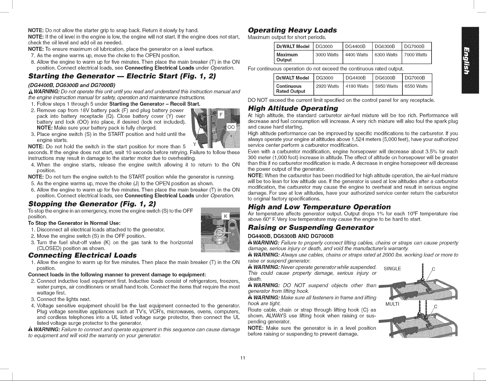
Stopping the Generator (Fig. 1, 2)
Tostop the engine inan emergency, move the engine switch (S) to the OFF
position.
To Stop the Generator in Normal Use:
1. Disconnect all electrical loads attached to the generator.
2. Move the engine switch (S) in the OFF position.
3. Turn the fuel shut-off valve (K) on the gas tank to the horizontal
(CLOSED) position as shown.
Connecting Electrical Loads
1. Allow the engine to warm up for five minutes. Then place the main breaker (T) in the ON
position.
Connect loads in the following manner to prevent damage to equipment:
2. Connect inductive load equipment first. Inductive loads consist of refrigerators, freezers,
water pumps, air conditioners or small hand tools. Connect the items that require the most
wattage first.
3. Connect the lights next.
4. Voltage sensitive equipment should be the last equipment connected to the generator.
Plug voltage sensitive appliances such at TV's, VCR's, microwaves, ovens, computers,
and cordless telephones into a UL listed voltage surge protector, then connect the UL
listed voltage surge protector to the generator.
A WARNING: Failure to connect and operate equipment in this sequence can cause damage
to equipment and will void the warranty on your generator.
Operating Heavy Loads
Maximum output for short periods.
DEWALT Model DG3000 DG4400B DG6300B DG7000B
Maximum 3000 Watts 4400 Watts 6300 Watts 7000 Watts
Output
For continuous operation do not exceed the continuous rated output.
DEWALTModel DG3000 DG4400B DG6300B DG7000B
Continuous 2920 Watts 4180Watts 5950 Watts 6550 Watts
Rated Output
DO NOT exceed the current limit specified on the control panel for any receptacle.
High Altitude Operating
At high altitude, the standard carburetor air-fuel mixture will be too rich. Performance will
decrease and fuel consumption will increase. A very rich mixture will also foul the spark plug
and cause hard starting.
High altitude performance can be improved by specific modifications to the carburetor. Ifyou
always operate your engine at altitudes above 1,524 meters (5,000 feet), have your authorized
service center perform a carburetor modification.
Even with a carburetor modification, engine horsepower will decrease about 3.5% for each
300 meter (1,000 foot) increase in altitude. The effect of altitude on horsepower will be greater
than this if no carburetor modification is made. A decrease in engine horsepower will decrease
the power output of the generator.
NOTE: When the carburetor has been modified for high altitude operation, the air-fuel mixture
will be too lean for low altitude use. If the generator is used at low altitudes after a carburetor
modification, the carburetor may cause the engine to overheat and result in serious engine
damage. For use at low altitudes, have your authorized service center return the carburetor
to original factory specifications.
High and Low Temperature Operation
Air temperature affects generator output. Output drops 1% for each 10°F temperature rise
above 60° R Very low temperature may cause the engine to be hard to start.
Raising or Suspending Generator
DG4400B, DG6300B AND DG7000B
_&WARNING: Failure to properly connect lifting cables, chains or straps can cause property
damage, serious injury or death, and void the manufacturer's warranty.
WARNING: Always use cables, chains or straps rated at 2000 Ibs. working load or more to
raise or suspend generator.
,& WARNING: Never operate generator while suspended.
This could cause property damage, serious injury or
death.
A WARNING: DO NOT suspend objects other than
generator from lifting hook.
A WARNING: Make sure all fasteners in frame and firing
hook are tight.
Route cable, chain or strap through lifting hook (C) as
shown. ALWAYS use lifting hook when raising or sus-
pending generator.
NOTE: Make sure the generator is in a level position
before raising or suspending to prevent damage.
SINGLE C
MULTI
11
Page 12
MAINTENANCE
Importance of Maintenance
Good maintenance is essential for safe, economical and trouble-free operation. It will also
help reduce air pollution.
WARNING: Improper maintenance or failure to correct a problem before operation can
cause malfunction, serious injury or death. Always follow the inspection and maintenance
recommendation and schedules in this manual
The following pages include a maintenance schedule, routine inspection procedures and
simple maintenance procedures using basic hand tools to help you properly care for your
generator. If you are not comfortable with any maintenance procedure, contact a DEWALT
factory service center or a DEWALT authorized service center.
Maintenance, replacement or repair of the emission control devices and system may be per-
formed by any engine repair establishment or individual using parts that are certified to EPA
standards.
Maintenance Safety
_, WARNING: Do not operate this unit until you read and understand this instruction manual and
the engine instruction manual for safety, operation and maintenance instructions..
SAFETY PRECAUTIONS
_, WARNING: Make sure the engine is off before beginning any maintenance or repairs. This
will eliminate several potential hazards, including:
• carbon monoxide poisoning from engine exhaust. Be sure there is adequate ventilation
whenever you operate the engine.
• burns from hot parts. Let the engine and exhaust system cool before you touch it to
prevent burns.
• injury from moving parts. Wear appropriate clothing, tie back long hair, and stay alert
around the generator to prevent injury from moving parts.
A WARNING: To reduce the possibility of fire or explosion, be careful when working around
gasoline. Use only a nonflammable solvent, not gasoline, to clean parts. Keep smoking prod-
ucts, sparks and flames away from aft fuel related parts.
Read all instructions before beginning and make sure you have the tools and skills required.
A DEWALT factory service center or a DEWALT authorized service center knows your generator
best and is fully equipped to do maintenance and repair. To ensure the best quality and reli-
ability, use only new genuine parts or their equivalents for repair or replacement.
General Maintenance
,& WARNING: Contact with a hot engine or exhaust system can cause serious burns or fires.
Let the engine and muffler cool before storing the generator.
NOTE: All generators contain maintenance parts (e.g. oil, filters, etc.) that are periodically
replaced. These used parts may contain substances that are regulated and must be disposed of
in accordance with local, state, provincial and federal laws and regulations.
NOTE: Take note of the positions and locations of parts during disassembly to make reassembly
easier.
NOTE: Any service operations not included in this section should be performed by a DEWALT
factory service center or a DEWALT authorized service center.
The following procedures must be followed when maintenance or service is performed on the
generator.
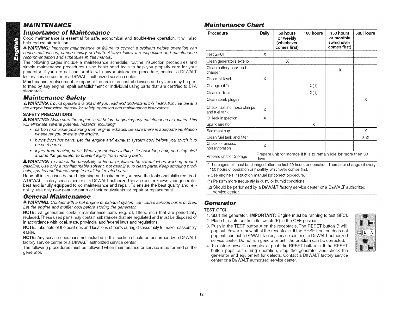
Maintenance Chart
Procedure
Test GFCI
Clean generator's exterior
Clean battery pack and
charger
Check oil level+
Change oil *+
Clean air filter +
Clean spark plugs+
Check fuel line, hose clamps
and fuel tank
iOil leak inspection
Spark arrestor
Sediment cup
Clean fuel tank and filter
Check for unusual
inoise/vibration
Prepare unit for Storage
i* The engine oil must be changed after the first 20 hours or operation. Thereafter change oil every
150 hours of operation or monthly, whichever comes first.
+ See engine's instruction manual for correct procedure.
(1) Perform more frequently in dusty or humid conditions
(2) Should be performed by a DEWALT factory service center or a DEWALT authorized
service center.
Daily
X
X
X
X
x
Prepare unit for storage if it is to remain idle for more then 30
days
50 hours
or weekly
(whichever
comes first)
X
100 hours
x(1)
x(1)
X
150 hours
or monthJy
(whichever
comesfirst)
500 Hours
X
X
X(2)
Generator
TEST GFCl
1. Start the generator.
2.
Place the auto control idle switch (P) in the OFF position.
3.
Push in the TEST button A on the receptacle. The RESET button B will
pop out. Power is now off at the receptacle. If the RESET button does not
pop out, contact a DEWALT factory service center or a DEWALT authorized
service center. Do not run generator until the problem can be corrected.
4.
To restore power to receptacle, push the RESET button in. If the RESET
button pops out during operation, stop the generator and check the
generator and equipment for defects. Contact a DEWALT factory service
center or a DEWALT authorized service center.
IMPORTANT: Engine must be running to test GFCI.
12
Page 13
CLEANING
WARNING: When cleaning, use only mild soap and a damp cloth on plastic parts. Many
household cleaners contain chemicals which could seriously damage plastic. Also, do not use
gasoline, turpentine, lacquer, paint thinner, dry cleaning fluids or similar products which may
seriously damage plastic parts. Never let any liquid get inside the tool; never immerse any
part of the tool into a liquid.
The generator should be kept clean and dry at all times. The generator should not be stored
or operated in environments that include excessive moisture, dust or any corrosive vapors.
If these substances are on the generator, clean with a cloth or soft bristle brush. Do not use
a garden hose or anything with water pressure to clean the generator. Water may enter the
cooling air slots and could possibly damage the rotor, stator and the internal windings of the
alternator.
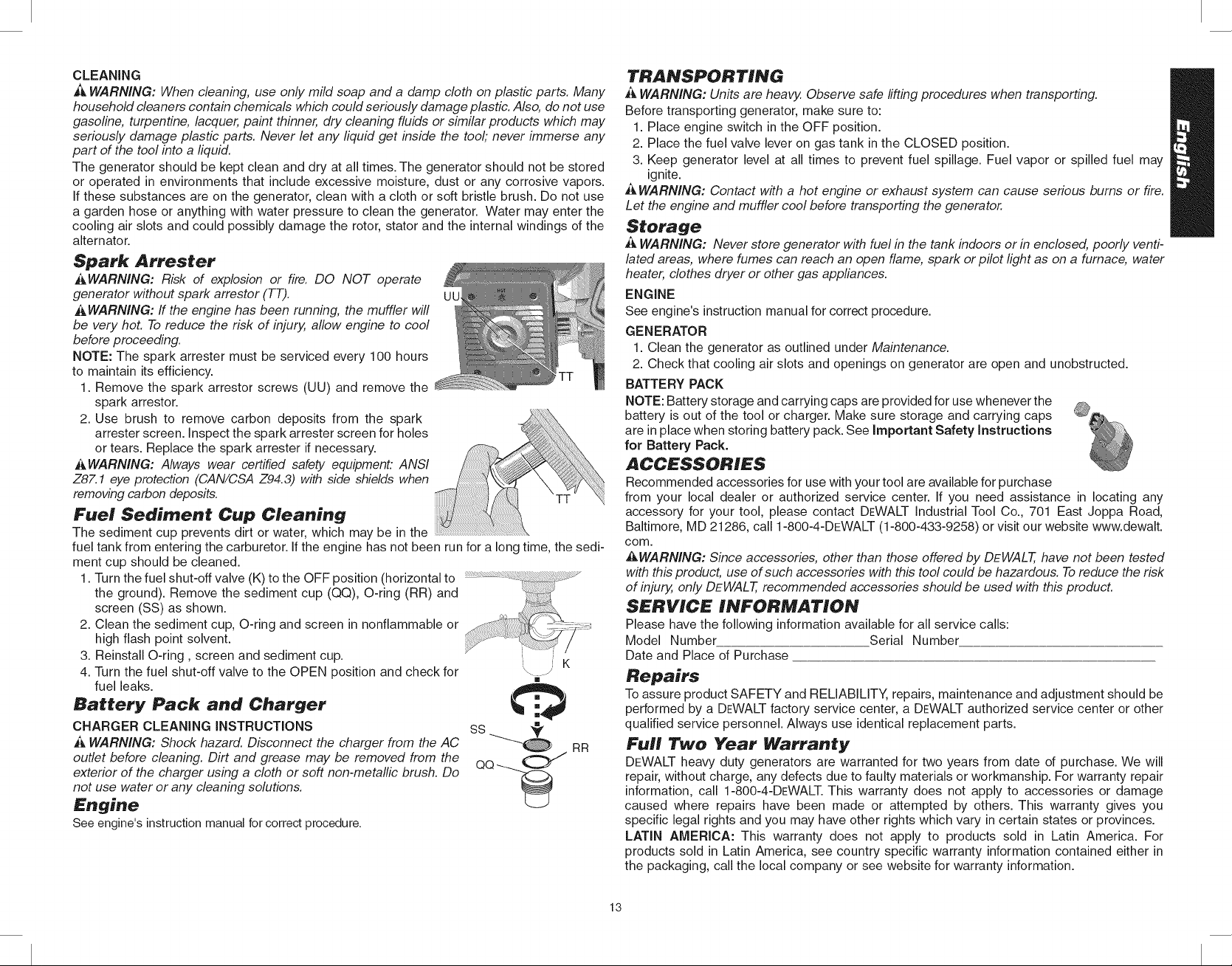
Spark Arrester
_WARNING: Risk of explosion or fire. DO NOT operate
generator without spark arrestor (TT). UU
_WARNING: ff the engine has been running, the muffler will
be very hot. To reduce the risk of injury, allow engine to cool
before proceeding.
NOTE: The spark arrester must be serviced every 100 hours
to maintain its efficiency.
1. Remove the spark arrestor screws (UU) and remove the
spark arrestor.
2. Use brush to remove carbon deposits from the spark
arrester screen. Inspect the spark arrester screen for holes
or tears. Replace the spark arrester if necessary.
_,WARNING: Always wear certified safety equipment." ANSI
Z87.1 eye protection (CAN/CSA Z94.3) with side shields when
removing carbon deposits.
Fuel Sediment Cup Cleaning
The sediment cup prevents dirt or water, which may be in the
fuel tank from entering the carburetor. If the engine has not been run for a long time, the sedi-
ment cup should be cleaned.
1. Turn the fuel shut-off valve (K) to the OFF position (horizontal to
the
ground). Remove the sediment cup (QQ), O-ring (RR) and
2. Clean the sediment cup, O-ring and screen in nonflammable or ,jj.s_
screen (SS) as shown.
high flash point solvent. _ ............... K3. Reinstall O-ring, screen and sediment cup.
4. Turn the fuel shut-off valve to the OPEN position and check for '_- -_
fuel leaks.
Battery Pack and Charger
CHARGER CLEANING INSTRUCTIONS
_ WARNING: Shock hazard. Disconnect the charger from the AC
outlet before cleaning. Dirt and grease may be removed from the
exterior of the charger using a cloth or soft non-metallic brush. Do
not use water or any cleaning solutions.
Engine
See engine's instruction manual forcorrect procedure.
,..'b
ss '_
Q_ RR
TRANSPORTING
_ WARNING: Units are heavy, Observe safe rifting procedures when transporting.
Before transporting generator, make sure to:
1. Place engine switch in the OFF position.
2. Place the fuel valve lever on gas tank in the CLOSED position.
3. Keep generator level at all times to prevent fuel spillage. Fuel vapor or spilled fuel may
ignite.
WARNING: Contact with a hot engine or exhaust system can cause serious burns or fire.
Let the engine and muffler cool before transporting the generator.
Storage
_J,WARNING: Never store generator with fuel in the tank indoors or in enclosed, poorly venti-
lated areas, where fumes can reach an open flame, spark or pilot light as on a furnace, water
heater, clothes dryer or other gas appliances.
ENGINE
See engine's instruction manual for correct procedure.
GENERATOR
1. Clean the generator as outlined under Maintenance.
2. Check that cooling air slots and openings on generator are open and unobstructed.
BATTERY PACK
NOTE: Battery storage and carrying caps are provided for use whenever the
battery is out of the tool or charger. Make sure storage and carrying caps
are in place when storing battery pack. See Important Safety Instructions
for Battery Pack.
ACCESSORIES
Recommended accessories for use with your tool are available for purchase
from your local dealer or authorized service center. If you need assistance in locating any
accessory for your tool, please contact DEWALT Industrial Tool Co., 701 East Joppa Road,
Baltimore, MD 21286, call 1-800-4-DEWALT (1-800-433-9258) or visit our website www.dewalt.
com.
_WARNING: Since accessories, other than those offered by DEWALT, have not been tested
with this product, use of such accessories with this tool could be hazardous. To reduce the risk
of injury, only DEWALT, recommended accessories should be used with this product.
SERVICE INFORMATION
Please have the following informationavailable for all service calls:
Model Number Serial Number
Date and Place of Purchase
Repairs
Toassure product SAFETY and RELIABILITY, repairs, maintenance and adjustment should be
performed by a DEWALT factory service center, a DEWALT authorized service center or other
qualified service personnel. Always use identical replacement parts.
FUll Two Year Warrant)/
DEWALT heavy duty generators are warranted for two years from date of purchase. We will
repair, without charge, any defects due to faulty materials or workmanship. For warranty repair
information, call 1-800-4-DEWALT. This warranty does not apply to accessories or damage
caused where repairs have been made or attempted by others. This warranty gives you
specific legal rights and you may have other rights which vary in certain states or provinces.
LATIN AMERICA: This warranty does not apply to products sold in Latin America. For
products sold in Latin America, see country specific warranty information contained either in
the packaging, call the local company or see website for warranty information.
13
Page 14
FREE WARNING LABEL REPLACEMENT: If your warning labels become illegible or are
missing, call 1-800-4-DEWALT for a free replacement.
TROUB£ESHOOT_NG GUIDE
This section provides a list of the more frequently encountered malfunctions, their causes
and corrective actions. The operator or maintenance personnel can perform some corrective
actions, and others may require the assistance of a qualified DEWALT technician or your
dealer.
Problem Code
Engine will not start (See engine instruction manual for more information) ................ 1,2,3,4
No electrical output ................................................................................................. 5,6,7,8,9,18
NOTE: Ifthere is still no power atthe receptacles, takethe generator to an authorized DEWALT
service center. To locate a DEWALTservice center nearest to you, call 1-800-4-DEWALT
Repeated circuit breaker tripping ....................................................................................... 10,11
Generator overheating ....................................................................................................... 10,12
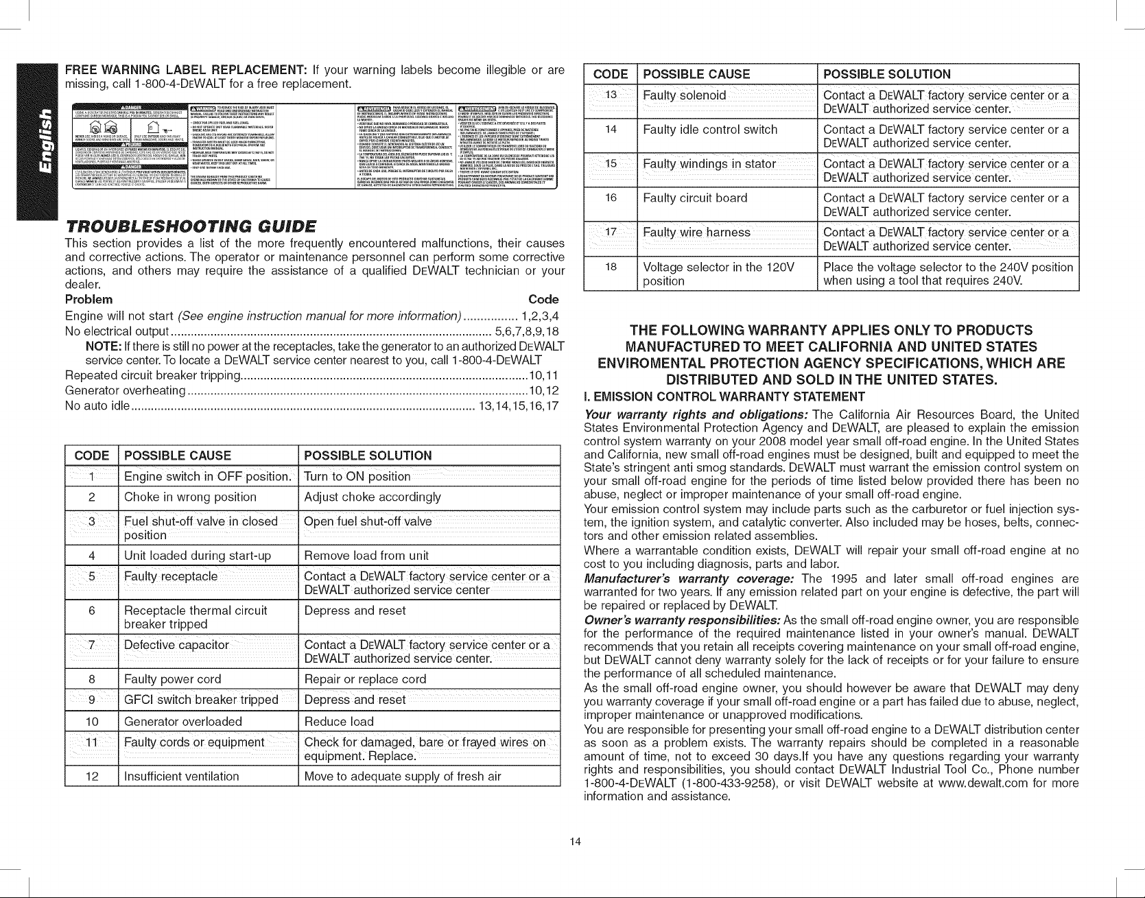
No auto idle ........................................................................................................ 13,14,15,16,17
CODE POSSIBLE CAUSE POSSIBLE SOLUTION
1 Engine Switch in OFF p0Siti0n.' Turn toON
2 Choke in wrong position Adjust choke accordingly
j Fuel Shut'off valve in cl0sed open rue! Shut,off va!ve
!position i
4 Unit loaded during start-up Remove load from unit
I
5 Faulty receptac!e Contact a DEWALT factory service center or a
: DEWALTauthorized service center
6 Receptacle thermal circuit Depress and reset
breaker tripped
I
Defective CapaCit0r Contact a DEWALT iact0rY service Center or a
• DEWALTauthorized service center:
8 Faulty power cord Repair or replace cord
9 GFCI switch breaker tripped Depress and reset
10 Generator overloaded Reduce load
11 Faulty c0rds or equipment CheCk foi damaged, baie or fiayed wireS on
'. equipment: Replacel
12 Insufficient ventilation Move to adequate supply of fresh air
CODE POSSIBLE CAUSE
Fauity so!enoid
I
14 Faulty idle control switch
POSSIBLE SOLUTION
Contact a DEWALT faCtorY Service Center 0ra
DEWALT authorized service center:
Contact a DEWALT factory service center or a
DEWALT authorized service center.
FaUlty windingS in Stator
Contact a DEWALT factorY ServiCe Centei ora
DEWALT authorized service center:
16 Faulty circuit board
Contact a DEWALT factory service center or a
DEWALT authorized service center.
FaUlty wire harness
i
18 Voltage selector in the 120V
position
Contact a DEWALT factoiy service Center or a
DEWALTauthorized service center:
Place the voltage selector to the 240V position
when using a tool that requires 240V.
THE FOLLOWING WARRANTY APPLIES ONLY TO PRODUCTS
MANUFACTURED TO MEET CALiFORNiA AND UNITED STATES
ENViROMENTAL PROTECTION AGENCY SPECiFiCATiONS, WHICH ARE
DiSTRiBUTED AND SOLD iN THE UNITED STATES.
i. EMiSSiON CONTROLWARRANTY STATEMENT
Your warranty rights and obligations: The California Air Resources Board, the United
States Environmental Protection Agency and DEWALT, are pleased to explain the emission
control system warranty on your 2008 model year small off-road engine. In the United States
and California, new small off-road engines must be designed, built and equipped to meet the
State's stringent anti smog standards. DEWALT must warrant the emission control system on
your small off-road engine for the periods of time listed below provided there has been no
abuse, neglect or improper maintenance of your small off-road engine.
Your emission control system may include parts such as the carburetor or fuel injection sys-
tem, the ignition system, and catalytic converter. Also included may be hoses, belts, connec-
tors and other emission related assemblies.
Where a warrantable condition exists, DEWALT will repair your small off-road engine at no
cost to you including diagnosis, parts and labor.
Manufacturer's warranty coverage: The 1995 and later small off-road engines are
warranted for two years. If any emission related part on your engine is defective, the part will
be repaired or replaced by DEWALT.
Owner's warranty responsibilities: As the small off-road engine owner, you are responsible
for the performance of the required maintenance listed in your owner's manual. DEWALT
recommends that you retain all receipts covering maintenance on your small off-road engine,
but DEWALT cannot deny warranty solely for the lack of receipts or for your failure to ensure
the performance of all scheduled maintenance.
As the small off-road engine owner, you should however be aware that DEWALT may deny
you warranty coverage if your small off-road engine or a part has failed due to abuse, neglect,
improper maintenance or unapproved modifications.
You are responsible for presenting your small off-road engine to a DEWALT distribution center
as soon as a problem exists. The warranty repairs should be completed in a reasonable
amount of time, not to exceed 30 days.If you have any questions regarding your warranty
rights and responsibilities, you should contact DEWALT Industrial Tool Co., Phone number
1-800-4-DEWALT (1-800-433-9258), or visit DEWALT website at www.dewalt.com for more
information and assistance.
14
Page 15
I1.EMISSION CONTROL SYSTEM WARRANTY
Emission Control System Warranty (ECS Warranty) for 1997 and later model engines
(a) Applicability: This warranty shall apply to 1997 and later model year engines. The ECS
Warranty Period shall begin on the date the new engine or equipment is purchased by/
delivered to its ultimate purchaser and shall continue for 24 consecutive months thereaf-
ter.
(b) General Emissions Warranty Coverage: DEWALT warrants to the ultimate purchaser of
the new engine or equipments and each subsequent purchaser for a two-year period.
(1) Designed, built and equipped so as to conform with all applicable regulations adopted
by the EPA and CARB pursuant to their respective authority, and
(2) Free from defects in materials and workmanship, which, at any time during the ECS
Warranty Period, may cause a warranted emissions-related part to fail to be identical in
all material respects to the part as described in the engine manufacturer's application
for certification.
The ECS Warranty only pertains to emissions-related parts on your engine, as fol-
lows:
(1) Any warranted, emissions-related parts that are not scheduled for replacement as required
maintenance in the Owner's Manual must be warranted for the ECS Warranty Period. If
any such part fails during the ECS Warranty Period, it shall be repaired or replaced by
DEWALT according to Subsection (4) below. Any such part repaired or replaced under the
ECS Warranty shall be warranted for the remainder of the ECS Warranty Period.
(2) Any warranted, emissions-related part that is scheduled only for regular inspection as
specified in the Owner's Manual must be warranted for the ECS Warranty Period. A state-
ment in such written instructions to the effect of "repair or replace as necessary" shall
not reduce the ECS Warranty Period. Any such part repaired or replaced under the ECS
Warranty shall be warranted for the remainder of the ECS Warranty Period.
(3) Any warranted, emissions-related part that is scheduled for replacement as required
maintenance in the Owner's Manual shall be warranted for the period of time prior to the
first scheduled replacement point for that part. If the part fails prior to the first scheduled
replacement, the part shall be repaired or replaced by DEWALT according to Subsection
(4) below. Any such emissions-related part repaired or replaced under the ECS Warranty
shall be warranted for the remainder of the ECS Warranty Period prior to the first sched-
uled replacement point for such emissions-related part.
(4) Repair or replacement of any warranted, emissions-related part under this ECS
Warranty shall be performed at no charge to the owner at a DEWALT Authorized
Warranty Service Facility. The warranty services or repairs must be provided at all
manufacturer distribution centers that are franchised to service the subject engines.
(5) When the engine is inspected by a DEWALT Authorized Warranty Service Facility, the
owner shall not be held responsible for diagnostic costs if the repair is deemed warrant-
able.
(6) DEWALT shall be liable for damages to other original engine components or approved
modifications proximately caused by a failure under warranty of any emission-related part
covered by the ECS Warranty.
(7) Throughout the ECS Warranty Period, DEWALT shall maintain a supply of warranted
emission-related parts sufficient to meet the expected demand for such emission-related
parts.
(8) Any replacement part may be used in the performance of any Warranty maintenance or
repairs and will be provided without charge to the ultimate purchaser. Such use shall not
reduce DEWALT's ECS warranty obligations.
(9) Add-on or modified parts that are not exempted by the Air Resources Board may not be
used. Such use will be grounds for disallowing a warranty claim made in accordance with
this article. DEWALT will not be liable under this article to warrant failures of warranted
parts caused by the use of such an add-on or modified part.
EMISSION RELATED PARTS INCLUDE THE FOLLOWING:
1) Fuel Metering System:
a) Gasoline carburetor assembly and its internal components.
b) Fuel filter (if equipped)
c) Carburetor gaskets
d) Fuel pump (if equipped)
2) Air Induction System including:
a) Intake pipe/manifold
b) Air cleaner
3) Ignition System including:
a) Spark plug
b) Ignition module/coil
4) Miscellaneous Items Used in Above Systems
a) Vacuum, temperature, and time sensitive valves and switches.
b) Hoses, belts, connectors, and assemblies.
5) Evaporate Emissions Control
a) Fuel Hose certificated for CARB evaporative emission of 2007.
b) Fuel hose clamp
c) carbon canister (if equipped)
d) Roll over valve (if equipped)
e) Fuel tank
f) Fuel cap
6) Exhaust Emissions Control
a) catalytic converter (if equipped)
15
Page 16

COlltlpos="_ ntS FiG. 1
A. Ensemble de roues et
A
poign6es (modUles
DG4400B, DG6300B et
DGTOOOB)
B. Moteur DEWALT
C. Barre de levage (compris
avec I'ensemble A)
(modUles DG4400B, j
DG6300B et DGTOOOB)
D. Panneau de commandes,
consulter la fig. 2 pour F
les modules distincts de
E. Filtre &air
K
Bj
L D
F. Bloc-piles de 18 volts
et chargeur DEWALT
panneaudecommande
(modUles DG6300B et
/
A
DGTOOOB)
G. Bouchon du r6servoir d'essence
H. R6servoir d'essence
I. Jauge & essence
J. Commande d'_trangleur
K. Soupape d'arrSt pour I'essence
L. Lanceur & ressort
M. Jauge d'huile
N. Bouchon de vidange du carter
O. R6servoir & charbon activ6 (le cas 6ch6ant)
R Soupape de transfert (si dot6)
Dispositions des panneaux de commandos
Q. Prise pour bloc-piles
(illustr6 avec bloc-piles)
R. Interrupteur de s61ection de tension
S. Interrupteur moteur
T. Coupe-circuit principal
U. Disjoncteurs thermiques de prise de courant
V. Prises de courant doubles GFCI (120 V)
W. Prises & verrouillage par rotation (120 V)
X. Prises a verrouillage par rotation (120/240 V)
Y. Syst_me de retenue du bloc-piles
Z. Interrupteur de commande de ralenti
c
G
FIG. 2
S
T W V / W
S
U
Q
T
Y
U T Q U Z
, X , _ S U T Q
M A
U V
W U U U
R y W U U R
Z
Fiche technique
IVlod_l
Alternateur
Type
Excitation Condensateur Condensateur
Sortie max. en c.a. (Watts) 3 000 4 400
Alimentation nominale en c.a. (Watts) 2 920 4 180
Courant nominal (A) 20 A 31,7/15,9 A
Moteur monophas6 monophas6
Fr6quence 60 60
Moteur
ModUle DW168F-2F DW177F-F
Puissance en HP (*puissance brute) *6,5 *9
Cylindr6e (CC) 196 270
Volume du r6servoir d'essence 3,3 (12,5 litres) 4,6 (17,4 litres)
(gallons)
Essence recommand6e Consulter le mode Consulter le mode
Volume d'huile Consulter le Consulter le
Type d'huile recommand6e Consulter le mode Consulter le mode
Capteur de bas niveau d'huile qui Oui Ou
commande I'arr_t moteur
Syst6me de d6marrage ,&,rappel ,&,rappel/D6marrage
16
DG3000 DG4400B
Sans brosses, & lame Sans brosses, & lame
double double
d'emploi du moteur d'emploi du moteur
mode d'emploi du mode d'emploi du
moteur moteur
d'emploi du moteur d'emploi du moteur
61ectrique
Page 17

Mod_l
DG3000
DG4400B
Prises
Double GFCI, 120 V,20 A
,A,verrouillage par rotation, 120 V,
Oui (1)
Oui (1)
Oui (2)
Oui (1)
20 A (NEMA L5-20R) +
,_,verrouillage par rotation, 120 V,
Non
Non
30 A (NEMA L5-30R) +
,Averrouillage par rotation, 120/240 V,
Non
Oui (1)
20 A (NEMA L14-20R) +
,_,verrouillage par rotation, 120/240 V,
Non
Non
30 A (NEMA L14-30R) +
G_n_rale
Dimensions g6n6rales"
(po/cm) (Long x Larg x Haut)
Poids & sec"
(23,6 x 19,3 x 20,5 po/
59,9 x 49,0 x 52,1 cm)
53,5 kg (118 Ib)
(28,0 x 21,7 x 21,5 po/
71,1 x 55,1 x 54,6 cm)
106 kg (234 Ib)
• Les dimensions ne comprennent pas la trousse des roues.
• Puissance brute (HP). Cette puissance nominale repr6sente la puissance maximale obtenue
en laboratoire & 3 600 tr/min en conformit6 avec la norme J1995 de test des moteurs de la
SAE (Society of Automotive Engineers) et n'est pr6sente qu'& titre indicateur uniquement
aux fins de comparaison. La puissance r6elle du moteur sera plus faible et variera selon
I'application, le r6gime et d'autres variables comme I'altitude et la temp6rature.
+ Lors de I'utilisation de prises b,verrouillage par rotation de 20 A ou 30 A, il est n6cessaire
de se brancher par I'interm6diaire d'un boitier multifonction Spider prot6g6 par GFCI ou
d'utiliser un adaptateur GFCI align&
Mod_l
DG6300B
DG7000B
Alternateu r
Type
Excitation
Sortie max. en c.a. (Watts)
Alimentation nominale en c.a. (Watts)
Courant nominal (A)
Moteur
Fr6quence (Hz)
Sans brosses, a lame
double
Condensateur
6 300
5 950
49,6/24,8
monophas6
6O
Sans brosses, & lame
double
Condensateur
7 000
6 550
54,6/27,3
monophas6
60
Moteur
ModUle
Puissance en HP (*puissance brute)
Cylindr6e (CC)
Volume du r6servoir d'essence
DW188F
"13
389
4,6 (17,4 litres)
DW188F
"13
389
4,6 (17,4 litres)
(gallons)
Essence recommand6e
Volume d'huile
Type d'huile recommand6e
Capteur de bas niveau d'huile qui
Consulter le mode
d'emploi du moteur
Consulter le
mode d'emploi du
moteur
Consulter le mode
d'emploi du moteur
Oui
Consulter le mode
d'emploi du moteur
Consulter le
mode d'emploi du
moteur
Consulter le mode
d'emploi du moteur
Ou
commande I'arrSt moteur
Mod_l DG6300 B DG7000 B
Syst6me de d6marrage ,A.rappel/D6marrage ,A.rappel/D6marrage
61ectrique 61ectrique
Prises
Double GFCI, 120 V, 20 A
,&,verrouillage par rotation, 120 V,
Oui (2) Oui (2)
Non Non
20 A (NEMA L5-20R) +
,_,verrouillage par rotation, 120 V,
Oui(2) Oui(2)
30 A (NEMA L5-30R) +
,&,verrouillage par rotation, 120/240 V,
Non Non
20 A (NEMA L14-20R) +
,Averrouillage par rotation, 120/240 V,
Oui (1) Oui (1)
30 A (NEMA L14-30R) +
G_n_rale
Dimensions g6n_rales"
(po/cm) (Long x Larg x Haut)
Poids & sec"
(28,0 x 21,7 x 21,5 po/
71,1 x 55,1 x 54,6 cm)
111,5 kg (246 Ib)
(28,0 x 21,7 x 21,5 po/
71,1 x 55,1 x 54,6 cm)
118,5 kg (261,5 Ib)
• Les dimensions ne comprennent pas la trousse des roues.
• Puissance brute (HP). Cette puissance nominale repr6sente la puissance maximale obtenue
en laboratoire & 3 600 tr/min en conformit6 avec la norme J1995 de test des moteurs de la
SAE (Society of Automotive Engineers) et n'est pr6sente qu'& titre indicateur uniquement
aux fins de comparaison. La puissance r6elle du moteur sera plus faible et variera selon
I'application, le r6gime et d'autres variables comme I'altitude et la temp6rature.
+ Lors de I'utilisation de prises b,verrouillage par rotation de 20 A ou 30 A, il est n_cessaire
de se brancher par I'interm6diaire d'un boitier multifonction Spider prot6g6 par GFCI ou
d'utiliser un adaptateur GFCI align&
L)e_finif:#ores : ##gnes directrices
en rnati_re de s_curit_
Les d_finitions ci-dessous d_crivent le niveau de gravit_ pour chaque symbole. Veuiiiez lirele
mode d'emploi et porter une attention particuii_re aces symboles.
_DANGER : Indique une situation dangereuse imminente qui, si elle n'est pas 4vit4e,
eausera la mort ou des blessures graves.
_kAVERTISSEMENT : Indique une situation potentiellement dangereuse quL si die n'est
oas 4vit4e, pourrait se solder par un d#ces ou des blessures graves.
_ATTENTION : Indique une situation potentiellement dangereuse qui, si elle n'est pas 4vit4e
pourrait se solder par des blessures mineures ou mod#r#es.
ATTENTION : Utilise sans le symbole d'alerte ala s4cufit4, indique une situation potentiellement
dangereuse quL si elle n'est pas 4vitee pourrait se solder par des dommages a la
propriete.
POUR TOUTE QUESTION OU COMMENTAIRE SUR CET OUTIL OU SUR TOUT AUTRE
OUTIL DEWALT,APPELEZ-NOUS SANS FRAIS AU NUMt_RO SUIVANT : 1-800-4-DEWALT
(I-800-433-9258)
Cons_gnes de s_curit_ #rnportaretes
_kDANGER : monoxyde de earbone. Le fonetionnement d'un moteur _ I'int#rieur
provoque la mort en quelques minutes. L'#chappement du moteur contient des niveaux
#lev#s de monoxyde de carbone (CO), un gaz toxique, inodore et invisible, fl est possible
que vous inhaliez du CO m#me EN L'ABSENCE de I'odeur de I'#chappement du moteur.
17
Page 18

AAVERTISSEMENT : ce produit et ses dmanations contiennent des produits chimiques
reconnus par I'Etat de la Califomie comme dtant cancdrig_nes et pouvant entrainer
des anomalies congdnitales ou d'autres probl_mes lids aux fonctions reproductrices.
, NE JAMAIS utiliser un moteur a I'intdrieur d'une habitation, de garages, d'un vide sanitaire
ou d'autres espaces partiellement clos. Cos endroits peuvent accumuler des niveaux
mortels de monoxyde de carbone. L'utilisation d'un ventilateur ou I'ouverture des fen#tres
et portes NE foumit PAS assez d'air frais.
, Utiliser UNIQUEMENT a I'extdrieur et loin de fen#tres, portes et #vents. En effet, cos
ouvertures peuvent aspirer I'#chappement du moteur a I'intdrieur d'un espace.
* M#me lots de I'utilisation correcte du moteur, le monoxyde de carbone pourrait pdndtrer
dans I'habitation. TOUJOURS utiliser un avertisseur de CO aliment# a pile ou un aver-
tisseur de CO de secours a pile dans la maison. Life et respecter toutes les directives
de I'avertisseur de CO avant son utilisation. En cas de malaise, #tourdissement ou
faiblesse, a tout moment, ddplacer la personne a I'air frais immddiatement. Consulter un
mddecin. Ce sont des signes d'intoxication oxycarbonde.
_,AVERTISSEMENT : ne pas utiliser I'appareil avant d'avoir lu et compris le mode d'emploi, et
celui du moteur ainsi que I'intdgralit# des directives de sdcurit#, d'utilisation et d'entretien.
IMPORTANT :ces produits sont dot6s de silencieux avec pare-6tincelles. Ce type de silen-
cieux est requis par la Loi dans I'Etat de la Californie Eabsence de pare-6tincelles est en
violation de I'article130050et/ou articles 4442 et 4443 du California Public Resources Code,
& moins que le moteur ne soit muni d'un pare-6tincelles comme stipul6 & I'article 4442 et
tenu en bon 6tat de fonctionnement. Les pare-6tincelles sont exig6s sur certaines terres du
Service des for6ts am6ricain et peuvent 6tre 6galement exig6s par d'autres 16gislations ou
ordonnances.
CONSERVER CES DIRECTIVES.
&DANGER : RISQUE D'ELECTROCUTION ET D'INCENDIE
Une inversion de polarisation dans le , N'inverser jamais la p01arit6&travers la
Syst_me 61ectrique d!un 6difice vers structure d!un syst_me 6!ectdque:
!e r6seau public pourrait blesser !es
m0nteurs de ligne qui travaillent & r6activer
le service.
• Une tentative de raccordement au systeme
d'alimentation du r6seau public pourrait se
solder par une electrocution.
• En rabsence d'un interrupteur bipolaire
de transfert, une re6nergisation, alors que
le g6nerateur est raccord6 au syst_me
d'alimentation, pourrait entrafner un
incendie ou provoquer des dommages
importants.
• La non-utilisation d'un interrupteur bipolaire
de transfert, Iorsque le g6nerateur est
raccord6 au syst_me 61ectriqued'une
structure, peut endommager les appareils
61ectriqueset ANNULERA la garantie du
fabricant.
Pour se raccorder & un syst_me 61ectrique
d'une structure de fa£on s6curitaire,
toujours faire installer un interrupteur
bipolaire de transfert, par un 61ectricien
qualifie, le tout en conformit6 avec los
ordonnances locales. (Utilisez au moins
un fil de calibre 10 Iorsde rinstallation d'un
interrupteur bipolaire de transfert.)
Eeau pout conduJre Ielectnc_te!De Ieau en FaJrefonct_onnerle generateur dans un
Contactavec des Co_posants s0us tension endroit propre SeCet bien a6r61S!aSsurer
pout transmettre I!e!ectricit6 au cadre et & que les mains sont s_ches avant de
d,autres surfaces provoquant ainsi un choc toucher I'appareil.
61ectrique& toute personne qui y touche.
• Un contact avec des rallonges us6es ou • Examiner los rallonges avant de los utiliser
endommag6es pourrait se solder par une et los remplacer avec une nouvelle rallonge
electrocution, au besoin.
, , .. . , . _ ....
Eut_hsat!ondune 0u de [a!!onges de calibre Ut!hser!e bon calibre de rallonge(s)
inf6rieur pourrait entrafner une surchauffe Correspondant & I'app!ication consulter la
des f!!s 0u des articles qui Ys0nt racc0rd6s rubrique utilisation de rai_onges dans !a
provoquant ainsi un incendie, section Assemblage.
• Eutilisation de rallonge(s) non raise(s) & la • Toujours utiliser une ou des rallonges
torte pourrait empdcher lefonctionnement munies d'un fil de raise &la terre et d'une
des coupe-circuits et se solder par un choc fiche correspondante convenable. NE
electrique. JAMAIS utiliser une prise non raise & la
terre.
une fuite acCidentelle de C0u[ant 61eCtrique ,installe r le g6ndrateur sU[ une surface de
P0urrait charger los surfaces c0nductdces faible conductivit6 c0mme une da!le de
en contact avec le g6n6[ateur, b6ton:TOUJOURS Se Se[vir du g6n6rateur
& une distance d au m0ins !,8 m (6 pi)de
toute surface C0nductrice.
Un hombre trop 61ev6 d'articles
raccord6s au g6n6rateur ou des articles
dont la classification de charge est tr_s
61ev6e pourrait(ent) exc6der la capacit6
nominale du g6n6rateur. Une telle
pratique pourrait provoquer la surchauffe
Consulter la rubrique Fonctionnement
pour charges a d6bit _iev_ dans la
section Fonctionnement. S'assurer que
la somme des charges 61ectriques de
tous los accessoires n'exc_de pas la
classification de charge du g6n6rateur.
de certains articles ou de leur c&blage,
pouvant se solder par un incendie ou un
choc electrique.
0 ¸ " • • " " • " _ " " "
LutMsat_on dun appare_ endomrnage Ne passe serv!r d un generateur qu_
ou qui ne foncflonne pas normalement pr6sente un trouble m6Canique 0u
pourrait se s01der par un incendie ou une 61ectriquel C0mmuniquer avec un Centre
61ectrocution de r6paration en usine de DEWALTou un
Centre de r6paration agr66 DEWALT.
• Le retrait de pi_ces protectrices pourrait • Ne pas se servir du g6n6rateur dans les
exposer des composants sous tension et pi_ces protectrices en position•
entrafner une 6,1ectrocution.
Le fonCtionnement de ce produit sans ¢:tie touj0uis pr6sent !0rsque le moteur
surveillance pourrait se solder par est en mamhel
des blessures personneHes ou des
dornrnages materiels, Afin de r_duire
le risque d'incendie; ne pas laisser le
moteur fonctionner sans surveillance.
18
Page 19

_,AVERTISSEMENT : RISQUE D'EXPLOSION OU D'INCENDIE
CE QUI PEUT SE PRODUIRE
• Les 6tincelles de produits du tabac, des
arcs 61ectriques, des gaz d'6chappement,
une flamme, des gaz et des composants
chauds du moteur comme le silencieux
peuvent enflammer I'essence renvers6e et
ses vapeurs.
• €:teindre le moteur et le laisser refroidir
event de retirer le bouchon du r6servoir et
faire rappoint d'essence.
• Etre attentif et 6viter de deverser de I'es-
COMMENT L'#VlTER
sence Iors du remplissage du reservoir.
S'assurer que le bouchon soit bien viss6
et d6placer I'appareil de lazone de ravi-
taillement event de demarrer le moteur.
* Le C0mbustible du r6servoir Sedilate S0us ,, Maintenir le niveau d'essence maximal
I'effet de la cha!eur et pourrait se solder sous !,6paulement du filtre & d6bris pour
par un d6versement et un incendie ou une permettre I'expansion de [essence.
explosion.
o Les mat6riaux combustibles qui tou- • Faire le plein d'essence & I'ext6rieur
chent les pi_ces chaudes du g6n6ra= dans une zone bien a6r6e. S'assurer de
teur risquent de s'enflammer. I'absence de source
d'inflammation pros de la zone de
ravitaillement, comme des produits du
tabac.
, Se servir du g6n6rateur dens une zone
propre, s_che et bien a6r6e & une dis-
tance minimale de 1,2 m (48 po) de tout
6difice, objet ou mur. Ne pas utiliser
I'appareil & I'int6rieur ou dens un endroit
exigu.
,, Utiliser uniquement le g6n6rateur dens
un endroit ouvert loin de broussailles ou
d'herbes s_ches ou de tout autre mat6-
riel combustible.
"De [esSence real entrepos6epourrait pro, EntreP0ser !!eSsence dens un Contenant
voquer un allumage (incendie) accidente!, homologu6 par I'QSHA (Sent6 et s6curit6
Ranger I'essence de fagon s6curitaire POUr du travail) dans un emp!acement S6cur!-
en emp6cher [acc_s aux enfants et & tOU, taire !oin de la z0ne de travai!.
tes autres personnes non qualifi6es_
. Le r6gime du moteur est r6gle en usine • Ne jamais essayer d',, acc61erer >>le
pour en assurer un fonctionnement s6curi- moteur pour obtenir un rendement
taire. Une alteration du r6glage du regime sup6rieur. Une telle pratique modifiera la
du moteur pourrait se solder par une sur- tension et frequence de sortie (hors des
chauffe des accessoires et provoquer un plages normalis6es) pouvant ainsi mettre
incendie. I'utilisateur ou les accessoires en danger.
_DANGER : RISQUE RESPIRATOIRE (ASPHYXIE)
CE QUI PEUT SE PRODUIRE COMMENT L'EVITER
,, I'inhalation des fum6es d'6chappement ,, NE JAMAIS utiliser un moteur &
provoquera de graves blessures, voJre le I'int6rieur d'une habitation, de garages.
d6ces! 1'6chappement du moteur contient d'un vide sanitaire ou d'autres espaces
des niveaux 61ev6s de monoxyde de partiellement clos. Ces endroits peuvent
carbone (CO), un gaz toxique, inodore et accumuler des niveaux mortels de
invisible. IIest possible que vous inhaliez monoxyde de carbone. Eutilisation d'un
du CO m6me en I'absence de I'odeur de ventilateur ou I'ouverture des fen6tres et
r6chappement du moteur, portes NE fournit PAS assez d'air frais.
• Utiliser uniquement & I'ext6rieur et
loin de fen6tres, portes et 6vents. En
effet, ces ouvertures peuvent aspirer
1'6chappement du moteur & I'int6rieur
d'un espace.
- Eloigner les enfants, animaux et _outeautre
personne de lazone de travail.
- Touiours tenir le tuyau d'6chappement
exempt de corps etrangers.
_.DANGER :RISQUE DE BLESSURE OU DE DOMMAGES MATERIELS
LORS DU TRANSPORT OU DE L'ENTREPOSAGE
CE QUI PEUT SE PRODUIRE COMMENT L'I_VITER
Lhuile et I'essence peuvent fuire ou se
d6verser.Cela pourrait se solder par un
incendie ou un danger d'inhalation; des
blessures graves ou un d6ces. Les fuites
d'huile endommageront le tapis, la peinture
ou toutes autres surfaces de vehicules ou
de remorques.
• Ne jamais transporter le g6nerateur avec
de ressence dens le syst_me, la soupape
& essence ouverte ou avec le g6n6rateur
en marche.
• Toujours installer le g6n6rateur sur un
rev6tement protecteur Iorsdu transport pour
proteger lev6hicule de tous dommages
associ6s aux fuites. Retirer imm6diatement
le g6n6rateur du v6hicule d_s rarriv6e &
destination. Toujours tenir le g6n6rateur &
niveau et ne jamais le d6poser sur son c6t6.
• Transporter ressence uniquement dens un
contenant homologue par I'OSHA.
19
Page 20

_,AVERTISSEMENT :ATTENTION SURFACES CHAUDES
CE QUI PEUT SE PRODUIRE COMMENT L'E_VITER
Un contact avec une surface m6tallique * Ne jamais toucher &des pi_ces
expos6e (silencieux et autres pi_ces du m6talliques expos6es sur le g6n6rateur
moteur) peut se solder par des brQlures pendant ou immediatement apres son
graves, utilisation. Le gen6rateur restera chaud
pendant plusieurs minutes apr_s son
utilisation.
• Ne pas toucher ni effectuer des
r6parations aux coiffes de protection avant
que le g6n6rateur n'ait refroidi.
_AVERTISSEMENT : RISQUE ASSOCIE AUX PIECES MOBILES
CE QUI PEUT SE PRODUIRE COMMENT L'E_VlTER
• Le moteur peut d6marrer accidentellement • Toujours d6brancher labougie d'allumage
sile volant est tourne manuellement ou par avant tout entretien.
raction de la corde du d6marreur.
,, Les pi_ces mobiles comme la poulie, le ,, Nejamais utiliser le g6n6rateur si les
volant ou lacourroie peuvent provoquer de protecteurs ou les couvercles sont
graves blessures si elles entrent en contact endommag6s ou retir6s.
avec vous ou vos v6tements. • Garder los cheveux, les v6tements et les
gants & 1'6cartdes pi#ces mobiles. Les
v6tements am pies, bijoux ou cheveux longs
pourraient s'enchev6trer dans les pieces
mobiles.
S'61oignerdes 6vents. car ces derniers
pourraient camoufler des pi_ces mobiles,
• Utiliser le g6nerateur avec des pieces
endommag6es ou manquantes ou le
reparer sans coiffes de protection risque de
vous exposer &des pieces mobiles et peut
se solder par de graves blessures.
Toutes les reparations requises pour ce
produit devraient 6tre effectu6es par un
centre de r6paration en usine de DEWALT
ou un centre de r6paration agr66
DEWALT.
_,AVERTISSEMENT : RISQUE ASSOCI=L A UTILISATION DANGEREUSE
CE QUI PEUT SE PRODUIRE COMMENT L'I_VITER
• Une utilisation dangereuse de votre
g6n6rateur pourrait provoquer de graves
blessures, voire votre d6c#s ou celui
d'autres personnes.
- Revoir et comprendre toutes les directives
et les avertissements contenus dans le
pr6sent mode d'emploi.
- Se familiariser avec le fonctionnement et
les commandes du g6n6rateur. Connaftre
le moyen de rarr6ter rapidement.
,, D6gager la zone de travail de toutes
personnes, animaux et obstacles.
• Tenir les enfants hors de portee du
g6nerateur en tout temps.
- Ne pas utiliser le g6n6rateur Iorsque
fatigu6 ou sous I'influence de ralcool ou de
drogues. Rester vigilant en tout temps.
,, Ne jamais rendre inop6rantes los
fonctionnalit6s de s6curit6 du produit.
,, installer un extincteur dans la zone de
travail.
• Ne pas utiliser le g6n6rateur iorsqu'il
manque des pi_ces ou si des pi_ces sont
bris6es ou non autoris6es.
• Nejamais se tenir debout sur le
gen6rateur.
Tout type de g6n6rateur domestique
essence peut produire des variations de
tenston endommageant ainsi les appareils
sensibles aux variations de tension ou
pourrait causer un incendie.
• Toujours utiliser un limiteur de surtension
homologu6 UL pour brancher les
appareils sensibles aux variations de
tension (t616viseur.ordinateur, chafne
st6r6ophonique, etc.). La non utilisation
d'un limiteur de surtension homologu6 UL
annulera la garantie de votre g6n6rateur.
AVIS : une bande d'alimentation &
plusieurs prises n'est pas un limiteur de
surtension. S'assurer d'utiliser un limiteur
de surtension homologue UL.
Mod_les DG440OB, DG6300B et DG7000B
Sou!ever ou Suspendre incorrectement Toujours utiliser des proc6du[es de
des g6n6rateurs dot6s de barres de !evage connexion c0nvenables c0mme ce!!es
pourrait entrafner une chute de I'appareil et d6crites dans le pr6sent mode d'emploi
prov0quer de graves b!essures, voire votre 1orsde !afixation de c&b!es, chafnes ou
propre d6c_s ou celu! d,autres personnes, sangles pour souleve[ ou suspendre !es
g6n6rateurs dot6s d'une barre de levagel
• Soulever ou suspendre incorrectement le • Toujours se servir de c&bles, chafnes
g6n6rateur risque de I'endommager. ou sangles pr6vus pour une charge
d'utilisation de 907,2 kg (2 000 Ib) ou plus
pour soulever ou suspendre le g6n6rateur.
20
Page 21

, Le g6n6rateur ne fonctionnera pas, Nejamais se Servir du g6n6rateur alorS
co[rectement suspendu. Cela pourra quli! est suspendu ou dans une position
I'endommager et pourrait provoquer de non hOrizontale.Toujours se servir du
graves b!essu res, voire votre propre d6c_s g@n#rateur surune surface p!ane de
ou celui d'autres personnes, nweau.
_kAVERTISSEMENT : RISQUE ASSOCIE AU BRUIT
CE QUI PEUT SE PRODUIRE COMMENT L'EVITER
•Dans certaines conditions, applications • Toujours utiliser un equipement de
et selon la dur6e d'utilisation, le bruit s6curite homologu6 : protection auditive
6mis par ce produit pourrait contribuer & conforme a la norme ANSI S12.6 (S3.19).
une perte auditive.
_&ATTENTION : RISQUE ASSOCIE AU TRANSPORT
CE QUI PEUT SE PRODUIRE COMMENT L'E_VlTER
• •
S0ulever un objet trop !ourd peut se s01der Le g6n6rateur est tr0p Iourd pour
par de graves b!essures: 6tre soulev6 par une seule personne,
Demander de Iiaide d!autres personnes
avant d'essayer de ie d6placer.
CONSERVER CES DIRECTIVES
Directives de $_curit_ irnportante$ pour los blocsopiles
MODELES DG4400B, DG6300B ET DG7000B
Un bloc-piles de 18 V DEWALT sert& d6marrer ces appareils avec la fonction de d6marrage
61ectrique. Pour la commande de blocs-piles de rechange, s'assurer d'inclure le num6ro de
catalogue et la tension :les blocs-piles & dur6e d'ex6cution prolong6e fournissent une dur6e
d'ex6cution 25 % sup6rieure & celle des blocs-piles standards. Consulter le tableau figurant & la
fin du pr6sent mode d'emploi pour connaitre la compatibilit6 des chargeurs et des blocs-piles.
REMARQUE : I'outil sera compatible avec les blocs-piles standards ou & dur6e d'ex6cution
prolong6e. Cependant, s'assurer de s61ectionner latension appropri6e.
Le bloc-piles n'est pas compl_tement charg6 & la sortie de I'emballage. Avant d'utiliser le
bloc-piles et le chargeur, lire les directives de s6curit6 ci-apr_s. Suivre les consignes de char-
gement d6crites.
LIRE TOUTES LES DIReCTIVeS.
o
Ne pas incin#rer le bloc-pries, m@mes'ri est tr#s endommag# ou compl@tement us#,
car il pout exploser au contact de flammes.
o
Une petite fuite de liquide peut se produire clans les ceriules du bloc-pries en
cas d'utriisation ou de conditions de temperature extr@mes; cela n'indique pas de
d@faillance. Toutefois, sile joint d'@tanch@it@ext@rieur est rompu et que le liquide entre en
contact avec la peau :
a. laver rapidement la zone touch@e au savon eta I'eau;
b. neutraliser I'effet au moyen d'un acide doux comme du jus de citron ou du vinaigre;
c. si le liquide entre en contact avec losyeux, losrincer abondamment a I'eau propre, pen-
dant au moins 10 minutes, et consulter imm#diatement un m@decin. (Remarque aux
fins m#dicales : le liquideest compos@ d'une solution de 25 % a 35 % d'hydroxyde de
potassium).
Charger les blocs-piles uniquement au moyen de chargeurs DEWALT.
• NE PAS @clabousser le bloc-piles ni I'immerger clans I'eau ou clans tout autre liquide.
Ne pas ranger ni utriiser le bloc-pries b un endroit ob la temperature
pourrait atteindre ou d#passer les 40,5 °C (105 °F) (comme clans les
remises ext#rieures ou les b#timents m#tariiques I'#t#).
&DANGER: risque d'@lectrocution. Ne jamais ouvrir le bloc-piles pour quelque
raison que ce soit. Sile bottler du bloc-piles est fissur@ ou endommag@, ne
pas I'ins#rer clans un chargeur. En effet, fly a risque de choc @lectrique ou
d'61ectrocution. Les blocs-piles endommag@s doivent @tre envoy@s au centre de r@paration
pour @trerecyclds.
REMARQUE : des capuchons sont fournis avec le bloc-piles en vue d'6tre utilis6s chaque
fois qu'on retire ce dernier du chargeur ou du g6n6rateur pour le ranger ou le transporter.
Enlever le capuchon avant de remettre le bloc-piles dans le chargeur ou le g6n6rateur.
• ,AVERTISSEMENT : risque d'incendie. Ne pas ranger ni ne transporter le bloc-pries
de mani@re # ceque des objets m#tariiques puissent entrer en contact avec les bornes
expos#es du bloc-pries. On ne dolt pas mettre, par exemple, le bloc-piles sans capuchon
dans un tablier, une poche, une boTte a outils, une bo_te de n@cessaire de produit, un tiroir, etc.
avec des clous, des vis, des cl@s,etc. Le transport des blocs-pries peut causer un incen-
die siles bomes entrent en contact involontairement avec des mati@res conductrices
comme des cl#s, de la monnaie, des outris manuels et d'autres #l#ments semblables.
La Hazardous Material Regulations (rdglementation sur los produits dangereux) du departe-
ment am@ricain des transports interdit en fait le transport des blocs,piles pour le commerce
et clans los avions (c.@-d. clans des valises et los bagages a main) A MOINS qu'ils ne soient
bien prot@g@scontre los courts-circuits. Pour le transport de blocs-piles individuels, on dolt
donc s'assurer que los homes sont protdg@es et bien isoldes contre toute mati6re pouvant
entrer en contact avec olios et causer un court-circuit.
Le sceau SRPRC TM
Le sceau SRPRC TM (Soci6t6 de recyclage des piles rechargeables au Canada)
appos6 sur les piles ou blocs-piles au nickel-cadmium et & hydrure m6tallique
de nickel indique que DEWALT d6fraie le coQt du recyclage de la pile ou du
bloc-piles b,la fin de sa vie utile. Dans certaines r6gions, il est ill6gal de jeter
les piles ou blocs-piles au nickel-cadmium dans les poubelles ou dans le sys-
t6me municipal de cueillette des r6sidus solides. Le programme de la SRPRC
repr6sente donc une alternative 6cologique.
Forganisme SRPRC TM, en collaboration avec DEWALT et d'autres utilisateurs de piles, a mis
sur pied des programmes aux ¢:tats-Unis et au Canada qui facilitent la collecte des piles et
blocs-piles au nickel-cadmium et & hydrure m6tallique de nickel 6puis6es. Aidez-nous & prot6-
geTI'environnement et &conserver nos ressources naturelles en retournant les piles au nickel
cadmium et & hydrure m6tallique de nickel 6puis6es & un centre de r6paration DEWALT ou
au d6taillant de votre r6gion pour qu'elles soient recycl6es. On peut 6galement communiquer
avec le centre de recyclage de la r6gion pour savoir ot_ d6poser les piles us6es.
SRPRCTM est une marque d6poseede la Soci6t6de recyclagedes pilesrechargeablesau Canada.
Directives de s_c_ri_ irnportan_es pour los
chargeurs de piles
CONSERVER CES DIRECTIVES :/e prdsent mode d'emp/oi confient des directives de s@cu-
ritd importantes sur les chargeurs de piles.
* Avant d'utiliser le chargeur, fire toutes los directives et tous los avertissements figurant sur
le chargeur, le bloc-piles et le produit utilis@avec le bloc-piles.
_DANGER : risque d'@lectrocution. Los homes de charge pr@sentent une tension de 120 V.
Ne pas sonder los bornes avec des objets conducteurs.
_kAVERTISSEMENT : risque de choc @lectrique. Eviter la pdndtration de tout liquide dans le
chargeur.
21
Page 22

A&ATTENTION : risque de brOlure. Pour r#duire le risque de blessures, charger seulement les
piles rechargeables au nickel-cadmium DEWALT.D'autres types de piles peuvent exploser et
provoquer des blessures corporelles et des dommages.
_&ATTENTION : clans certaines circonstances, Iorsque le chargeur est branch# au bloc d'afi-
mentation, les contacts de chargement expos#s a I'intdrieur du chargeur peuvent #tre court-
circuit#s par des corps dtrangers conducteurs tels que, mais sans s'y limiter, la laine d'acier, le
papier d'aluminium, ou toute accumulation de particules metalliques. IIs doivent #tre maintenus
distance des ouvertures du chargeur. Debrancher syst#matiquement celui-ci si aucun bloc-
piles n'y est ins#r#. Debrancher le chargeur avant tout nettoyage.
* NE PAS charger le bloc-piles au moyen de tout autre chargeur que ceux qui sont
mentionn_s dans le present mode d'emploL Le chargeur et le bloc-piles sont speciale-
ment con_us pour #tre utilises ensemble.
* Ces chargeurs ne sont pas destines _ #tre utilis#s # d'autres fins que celles de
charger les piles rechargeables DEWALT. Toute autre utilisation risque de provoquer un
incendie, un choc #lectrique ou une #lectrocution.
* Ne laisser pas le chargeur se mouiller.
* NE PAS UTILISER LE CORDON D'AMMENTATION DE FA_ON ABUSIVE. Ne jamais
transporter le chargeur par son cordon ou tirer sur ce dernier pour le d#brancher
de la prise. Tirer sur la fiche plut6t que sur le cordon pour ddbrancher le chargeur. Cela
permettra de reduire le risque d'endommager la fiche ou le cordon d'alimentation. Faire
remplacer immediatement un cordon d'alimentation ou un renfort de cordon us# ou
endommag#.
* S'assurer que le cordon est situ# en lieu sOr de mani#re _ ce que personne ne mar-
che nine tr#buche dessus ou b ce qu'il ne soit pas endommag# ni soumis b une
tension.
* Ne pas utiliser de rallonge _ moins que cela ne soit absolument n#cessaire.
L'utilisation d'une rallonge inad#quate risque d'entraTner un incendie, un choc #lectrique
ou une dlectrocution.
* Pour la s#curit# de I'utilisateur, utiliser une rallonge de calibre ad#quat (AWG,
American Wire Gauge [calibrage am#ricain normalis# des ills]). Plus le num#ro de
calibre de fil est petit et plus sa capacit# est grande, par exemple un calibre 16 a plus
de capacitd qu'un calibre 18. Si plus d'une rallonge est utilisee pour obtenir la Iongueur
totale, s'assurer que chaque rallonge pr#sente au moins le calibre de fil minimum. Si la
rallonge sera utilisee a I'ext#rieur, die dolt #tre estampill#e d'un W-A ou d'un W suivi de la
classification de la rallonge. Par exemple - SJTW-A indique que la rallonge peut s'utiliser
I'exterieur.
Calibre minimal recommand_ pour les rallonges
Longueur totaie de la rallonge
25 pi 50 pi 75 pi 100 pi 125 pi 150 pi 175 pi
7,6 m 15,2 m 22,9 m 30,5 m 38,1 m 45,7 m 53,3 m
Calibre de fil AWG
18 18 16 16 14 14 12
* Ne pas mettre d'objet sur le chargeur ni mettre ce dernier sur une surface molle
pouvant obstruer les fentes de ventilation et ainsi provoquer une chaleur interne
excessive. E-Ioignerle chargeur de toute source de chaleur. La ventilation du chargeur se
fait par les fentes pratiqu4es dans les parties superieures et inf#rieures du bMtier.
* Ne pas faire fonctionner le chargeur si la fiche ou le cordon est endommag#; les
remplacer imm#diatement.
* Ne jamais se servir d'un chargeur qui a encaiss# un coup brusque, qui est tomb#
ou qui est endommag#. Le faire v#rifier dans un centre de r#parations autoris#.
* Ne pas d#monter le chargeur; I'apporter _ un centre de r#paration autoris# Iors-
qu'un entretien ou une r#paration est requis. Le remontage non conforme du chargeur
comporte des risques d'incendie ou d'dlectrocution.
o
D#brancher le chargeur avant de le nettoyer. Cela r#duira le risque de choc #lectri-
que. Le risque ne sera pas #limin# en enlevant simplement le bloc-piles.
o
NE JAMAIS tenter de relier deux chargeurs ensemble.
o
Le chargeur est con_u pour #tre aliment# en courant domestique standard
(120 V). Ne pas utfliser une tension sup#rieure pour le chargeur. Cela ne s'applique
pas au chargeur pour poste mobile.
CONSERVER CES DIRECTIVES
POUR UN USAGE U£T_:'RIEUR
Procedure de charge
MODELES DG4400B, DG6300B ET DG7000B
_DANGER : risque d'dlectrocution. Les bornes de charge prdsentent une tension de 120 V.
Ne pas sonder les bornes avec des objets conducteurs.
1. Brancher le chargeur dans une prise appropri6e avant d'ins6rer le
bloc-piles.
2. Retirer les capuchons du bloc-piles et I'ins6rer dans le chargeur.
Le voyant rouge (charge en cours) clignotera continuellement
pour indiquer que la charge a d6but&
3. La fin de la charge sera indiqu6e par le voyant rouge qui
demeurera allum& Le bloc-piles est charg6 & plein et peut 6tre
utilis6 ou laiss6 dans le chargeur.
Utilisation du mode tune-up TM automatique
MODELES DG4400B, DG6300B ET DG7000B)
Le mode de Tune-Up TM automatique 6galise ou 6quilibre chaque cellule du bloc-piles pour
lui permettre de fonctionner & son rendement optimum. Les blocs-piles doivent 6tre r6gl6s
chaque semaine ou apr_s une dizaine de cycles de charges/d6charges ou chaque fois que
la dur6e de fonctionnement du bloc-piles diminue. Pour utiliser le Tune-Up TM automatique,
mettre le bloc-piles dans le chargeur et I'y laisser pendant au moins 8 heures.
Fonctionnement du voyant
CHARGEMENTDU
BLOC=PILES ................................ =msm =msm =msm =msm =msm =msm
CHARGE A BLOC .......................
RETARDEMENT BLOC=PILES
CHAUD/FROID ............................. _ [] _ [] _ [] _ [] _ []
REMPLACERLEBLOC=PILES...®®®® ®®®O® ®®®O® O®®O® •
SOURCE D'ALIMENTATION
iNADEQUATE ............................... ® ® _ ® ® ® ® ® ® ® ® ® ® ®
Voyants de charge
MODELES DG4400B, DG6300B ET DG7000B
Certains chargeurs sont conqus pour d6tecter certains troubles pouvant survenir avec les
blocs-piles. IIs sont indiqu6s par le clignotement rapide du voyant rouge. Dans ce cas, r6in-
s6rer le bloc-piles dans le chargeur. Si le trouble persiste, essayer un bloc-piles diff6rent
afin de d6terminer si le chargeur est en bon 6tat. Si le nouveau bloc-piles est charg6 cor-
rectement, cela signifie que le bloc-piles initial 6tait d6fectueux et qu'il dolt 6tre retourn6 &
un centre de r6paration ou & un site de collecte pour le recyclage. Si le nouveau bloc-piles
pr6sente le m6me trouble que celui d'origine, faire v6rifier le chargeur par un centre de
r6paration autoris&
22
Page 23

FONCTION DE SUSPENSION DU BLOC-PILES CHAUD/FROID
Certains chargeurs comportent une fonction de suspension du bloc-piles chaud/froid. En effet,
Iorsque le chargeur d6tecte un bloc-piles chaud, il suspend imm6diatement le chargement
jusqu'au refroidissement de celui-ci. Une fois le bloc-piles refroidi, le chargeur passe automa-
tiquement au mode de charge du bloc-piles. Cette fonction assure une dur6e de vie maximale
au bloc-piles. Le voyant rouge 6met un clignotement long, puis court en mode de suspension
de bloc-piles chaud.
PROBL#ME AVEC LE SECTEUR
Certains chargeurs pr6sentent un voyant pour indiquer tout probl_me avec ralimentation
secteur. Lorsque le chargeur est utilis6 avec des blocs d'alimentation portatifs comme des
g,_n6ratrices ou des alternateurs, le chargeur pout suspendre temporairement son fonction-
nement et un voyant rouge 6met deux ciignotements rapides suivis d'une pause. Cela
indique que le bloc d'alimentation est hors tol6rance.
BLOC-PILES LAISSI_ DANS LE CHARGEUR
Le chargeur et le bloc-piles peuvent 6tre laiss6s branch6s, le voyant rouge demeurant ind6fi-
niment allum& Le chargeur maintiendra le bloc-piles charg6 & plein et en bon 6tat.
REMARQUE : le bloc-piles perdra lentement sa charge une fois retir6 du chargeur. Si le bloc-
piles n'a pas 6t6 maintenu charg6 (charge d'entretien), il peut falloir le recharger avant de I'uti-
liser. De plus, un bloc-piles pout perdre lentement sa charge s'il est laiss6 dans un chargeur
qui n'est pas branch6 a une source de c.a. appropri6e.
BLOCS-PILES faibles : les chargeurs peuvent 6galement d6tecter les blocs-piles faibles.
Ces blocs-piles peuvent encore 6tre utilis6s, mais il faut s'attendre &un rendement moindre.
Dans un tel cas, environ 10 secondes apr_s I'insertion du bloc-piles, le chargeur 6mettra
rapidement un bip sonore & 8 reprises pour indiquer qu'un bloc-piles est faible. Le chargeur
chargera ensuite le bloc-piles au maximum de sa capacit&
Rernarques irnportantes pour le chargernent
1. Pour augmenter la dur6e de vie du bloc-piles et optimiser son rendement, le charger & une
temp6rature entre 18 et 24 °C (65 et 75 °F). NE PAS charger le bloc-piles & des temp6ra-
tures inf6rieures & 4,5 °C (40 °F) ou sup6rieures & 40,5 °C (105 °F). Cos consignes sont
importantes et permettent d'6viter d'endommager gravement le bloc-piles.
2. Le chargeur et le bloc-piles peuvent devenir chauds au toucher pendant la charge. II
s'agit d'un 6tat normal et cola n'indique pas un probl_me. Pour faciliter le refroidissement
du bloc-piles apr_s son utilisation, 6viter de mettre le chargeur ou le bloc-piles dans un
endroit chaud comme dans une remise m6tallique ou une remorque non isol6e.
3. Si le bloc-piles ne se charge pas ad6quatement, on dolt :
a. v6rifier le courant & la prise en branchant une lampe ou un autre appareil 61ectrique;
b. v6rifier si la prise est reli6e &un interrupteur de lumi_re qui la met hors tension Iorsque
vous 6teignez les lumi_res;
c. d6placer le chargeur et le bloc-piles &un endroit oQ la temp6rature ambiante est entre
18 °C et 24 °C (65 °F et 75 °F); et
d. si le probl_me persiste, apporter ou envoyer I'outil, le bloc-piles et le chargeur au
centre de r6paration de votre r6gion.
4. Le bloc-piles dolt 6tre recharg6 Iorsqu'il n'arrive pas & produire suffisamment de puissance
pour des travaux qui 6talent facilement r6alis6s auparavant. NE PAS CONTINUER & utiliser
le bloc-piles dans ces conditions. Suivre les proc6dures de charge. On pout 6galement
recharger en tout temps un bloc-piles partiellement d6charg6 sans nuire & son fonctionne-
mont.
5. Dans certaines circonstances, Iorsque le chargeur est branch6 au bloc d'alimentation, les
contacts de chargement expos6s & I'int6rieur du chargeur peuvent 6tre court-circuit6s par
des corps 6trangers conducteurs tels que, mais sans s'y limiter, la laine d'acier, le papier
d'aluminium, ou toute accumulation de particules m6talliques. IIs doivent 6tre maintenus
& distance des ouvertures du chargeur. D6brancher syst6matiquement celui-ci si aucun
bloc-piles n'y est ins6r& D6brancher le chargeur avant tout nettoyage.
6. Ne pas geler ni immerger le chargeur dans I'eau ou dans tout autre liquide.
&AVERTISSEMENT : risque de choc 61ectrique. Eviter la p6netration de tout fiquide clans le
chargeur.
&ATTENTION : ne jamais ouvrir le bloc-piles pour quelque raison que ce soil Si le boTtier de
plastique du bloc-piles est brise ou fissur6, le retourner a un centre de r6paration pour qu'il
soit recycl6.
Chargernent de piles ¢l'outil _lectrique portatif
&AVERTISSEMENT : les chargeurs de type condensateur ne doivent pas #tre utilises
avec des gen6rateurs portatifs. La puissance irr6guli#re du g6nerateur pourrait provoquer la
defaillance d'un chargeur de type condensateur. DEWALT a fabrique des chargeurs de ce type
par le passe. (modUles DW9104 et DW9106). Pour toutes questions concernant I'utilisation
d'un chargeur DEWALT avec un generateur, composer le 1-800-4-DEWALT.
REMARQUE : d'autres fabricants de chargeurs de pile ont et fabriquent toujours des char-
geurs de type condensateur. Communiquer avec I'un d'entre eux pour connaitre s'il est s6cu-
ritaire d'utiliser des chargeurs avec des g6n6rateurs portatifs.
ASSEMBLAGE
Mise _ ia terre du g_n_rateur
Le g6n6rateur dispose d'un boulon de mise &la terre (VV) qui
s'utilise Iorsque les ordonnances locales en mati_re d'61ectri-
cit6 I'exigent. Se reporter & la disposition 250 du Code natio-
nale de 1'61ectricit6pour pr6ciser toute information relative &
la mise & la terre. Votre compagnie d'61ectricit6 locale ou un
61ectricien agr66 devrait 6tre en mesure de vous aider avec
cette information.
REMARQUE : votre moteur est d6j& mis & la terre au cadre
avec un ruban de mise & la terre.
Utilisation de ralionges
&AVERTISSEMENT : se servir uniquement de rallonges mises a la terre. Utiliser uniquement
des outils #lectriques a trois ills ou a double isolation.
Utiliser uniquement des rallonges con(_ues pour une utilisation ext6rieure et munies d'un
troisi_me fil pour mise & la terre. Lors de rutilisation de prises &verrouillage par rotation de 20 A
ou 30 A, il est n6cessaire de se brancher par rinterm6diaire d'un boftier multifonction Spider
prot6g6 par GFCI ou d'utiliser un adaptateur GFCI align&
Une chute de tension se fera sentir Iors de rutilisation d'une Iongue rallonge pour relier un appa-
reil ou un outil 61ectrique au g6n6rateur. Plus la rallonge est Iongue, plus grande sera la chute
de tension. Ainsi, I'appareil ou routil 61ectrique re(_oitmoins de tension. La quantit6 de courant
(amperes) d6bit6e augmentera ou I'appareil soufffira d'une r6duction de rendement. Une ral-
Ionge plus Iourde munie de fil plus 6pals r6duira la porte de tension. S'assurer de s61ectionner
une rallonge qui acheminera une tension suffisante pour alimenter I'outil ou rappareil 61ectrique.
Les tableaux affichent le calibre appropri6 des rallonges ainsi que la chute de tension provoqu6e
par rutilisation de rallonges selon diverses charges 61ectriques.
&ATTENTION : le fonctionnement d'appareils sous basso tension provoquerait une surchauffe.
L'utilisation d'une rallonge excessivement Iongue la surchauffera.
&AVERTISSEMENT : maintenir les rallonges en bon #tat de fonctionnement. Ne pas utiliser de
rallonges usees, denudees ou effilochees. En effet, une telle pratique risque de provoquer un
choc _lectrique.
23
Page 24

CALIBREMINIMUM POUR ENSEMBLES DE RALLONGES
Tension Longueur totaie du cordon en m_tres (en pieds)
120V
240 V
Intensit_ nominaie
0-10
10-13
13-16
16-25
25-30
L0ngueurde ra,onge
7,6m
25 pi
15,2 m
50 pi
L0ngueurde ara,o"ge
30,5 m
100 pi
45,7 m
150 pi
Assemblage des accessoires
MOD#LES DG4400B, DG6300B ET DG7000B
Les accessoires offerts avec les g6n@ateurs comprennent les roues (A), les poign_es (A)
et la barre de levage (C). REMARQUE : deux personnes sont n6cessaires pour en faire
I'installation. Installer I'ensemble des roues avant I'ajout d'essence ou d'huile moteur pour
empScher tout dommage au moteur. Si I'installation des accessoires s'effectue apr_s le
fonctionnement du g6n@ateur, s'assurer que !e r6servoir d'essence soit vide, que la soupape
d'arrSt pour I'essence soit en position FERMEE (horizontale par rapport au sol) et que I'huile
moteur soit vidang6e. La figure 3 illustre le contenu de I'ensemble d'accessoires.
REMARQUE : apr_s un fonctionnement d'environ 20 heures, il est possible que les boulons
des accessoires soient I&ches. Les resserrer au besoin.
0-6,7 m
(0-25 pi)
0-15,2 m
(0-50 pi)
AWG
4,9 (16)
4,9 (16)
4,3 (14)
3,7 (12)
10
7,9-15,2 m 15,5-30,5 m
(26-50 pi) (51-100 pi)
15,5-30,5 m 30,8-60,9 m
(51-100 pi) (101-200 pi)
4,9 (16)
4,9 (16)
4,3 (14)
3,7 (12)
10
4,3 (14) 4,3 (14)
4,3 (14) 3,7 (12)
3,7 (12) 3,7 (12)
3,7 (12) 10
10 Non recommand6
30,8-45,7 m
(101-150 pi)
61,2-91,4 m
(201-300 pi)
Charge en Chute de tension ....
amperes 16 AWG 14 AWG 12 AWG 10 AWG
10A
15A
20 A
30 A
10A
15A
20 A
30 A
2,0
3,0
4,0
6,0
4,0
6,0
8,0
12,0
1,3
1,9
2,5
3,8
2,5
3,8
5,0
7,5
0,8 0,5
1,2 0,8
1,6 1,1
2,3 1,6
1,6 1,1
2,3 1,6
3,1 2,1
4,7 3,2
Charge en Chute de tension
amperes 16 AWG 14 AWG 12 AWG 10 AWG
10A
15A
2O A
3O A
10A
15A
2O A
3O A
8,0
120
16,0
24,0
120
18,0
24 0
36,0
5,0
7,5
10,0
15,0
7,5
11,3
150
22,5
3,1
4,7
6,2
9,3
4,7
7,0
9,3
14,0
2,1
3,2
4,2
6,3
3,2
4,7
6,3
9,5
LL
JJ
CC
KK
DD @@@@ gg
Assemblage de I'ensemble des roues
&ATTENTION : Risque associ# au transport. Le g#n#rateur est trop Iourd pour #tre soulev#
par une seule personne. Demander de I'aide avant de le soulever.
1. Incliner d61icatement le g6n@ateur de sorte qu'il
repose sur le c6t6 moteur. _._
2. Assembler les deux pieds portants (AA) au cadre y
inf@ieur. Assembler I'essieu des roues (BB) au cadre GG
sup@ieur. Utiliser les boulons courts (CC) pour ces
deux @apes.
3. Enfiler les deux grandes rondelles (DD) sur chaque
extr6mit6 de I'essieu. Ins@er les roues (EE) sur I'es-
sieu.
4. Enfiler les deux petites rondelles (FF) sur I'essieu,
contre les roues et fixer en position avec les goupilles fendues (GG).
5. Remettre le g6n@ateur &la verticale sur ses pieds portants et roues.
Assemblage de I'ensemble des poign_es
1. Installer les poign6es du c6t6 du moteur du g6n@ateur. Placer le JJ
module de poign6e (HH) sur les barres sup@ieures horizontales
puis ins@er la bride inf@ieure (JJ). HH
2. Utiliser les longs boulons (KK) pour fixer ensemble les brides
inf@ieures et sup@ieures.
3. Setter les boulons jusqu'& ce que le module soit serr6 ou que
1'6cart entre les deux brides soit ferm&
Assemblage de la barre de levage
1. Ins@er la barre de levage (MM) --_l
sous les deux barres horizon- I
tales et la positionner comme i
indiqu&
2. Placer la bride sup@ieure (LL)
par-dessus les barres horizon-
tales et la fixer & la barre de
levage avec les longs boulons
(KK).
3.
Positionner la barre de levage comme indiqu_ et r6gler le bon emplacement selon le
module :
ModUles DG4400B et DG6300B : positionner le bord de la barre de levage & 318 mm
(12,5 po) du bord du cadre comme indiqu&
ModUle DG7000B : positionner le bord de la barre de levage & 31;1 cm (12,25 po) du
bord du cadre comme indiqu&
24
AA
KK
Page 25

4.Serrerfermementlesboulonsjusqu'&ceque1'6cartentrelabridesup@ieureetlabarre
delevagesoitclos.
Chargeurs
MODELES DG4400B, DG6300B ET DG7000B
Le bloc-piles de 18 V utilise un chargeur de 18 V DEWALT (inclus). Le bloc-piles peut @re
6galement charg6 au moyen d'un chargeur 1 heure, d'un chargeur 15 minutes ou d'un char-
geur 12 volts pour poste mobile DEWALT.S'assurer de lire toutes les directives de s6curit6
avant d'utiliser le chargeur. Consulter le tableau figurant & la fin du pr6sent mode d'emploi
pour connaftre la compatibilit6 des chargeurs et des blocs-piles.
Ajout d'huile rnoteur et d'essence
IMPORTANT! Le moteur en provenance de I'usine NE CONTIENT PAS d'huile. II faut ajouter
de I'huile au moteur avant de s'en servir pour emp#cher tout dommage.
AJOUT D'HUILE MOTEUR
Consulter le mode d'emploi du moteur pour la bonne procedure.
AJOUT D'ESSENCE AU MOTEUR (FIG. 1)
_,AVERTISSEMENT : risque d'explosion ou d'incendie. Les vapeurs d'essence sont haute-
ment inflammables. Faire le plein de prdf6rence a I'ext6rieur ou seulement clans des endroits
bien aer6s. Ne pas faire le plein ou ne pas v6rifier le niveau d'essence avec le moteur en
marche, hie pas ranger I'essence, ni la d6verser ou I'utiliser pres d'une flamme nue, d'une
source d'6tincelles (comme la soudure) ou d'6quipement 61ectrique en fonctionnement. Ne
pas fumer lots du plein d'essence.
1. D_visser et retirer le bouchon du r6servoir d'essence (G).
2. Ajouter de I'essence sans plomb r_guli@e propre et neuve dans le
REMARQUE : ne pas m61anger I'huile et I'essence.
&AVERTISSEMENT : ne jamais faire le plein d'essence d'un reservoir.
r6servoir d'essence (H) avec un indice d'octane d'au moins 86.
Ne pas remplir au-dessus de 1'6paulement du filtre a debris (NN) comme
indique, pour permettre I'expansion de I'essence. Essuyer toute trace ..............................................................
d'essence du moteur et de 1'6quipement avant de d6marrer le moteur.
3. Remettre le bouchon du r6servoir d'essence en place. Visser le bouchon en sens horaire
jusqu'& ce qu'il se bloque.
PANNEAU DE COMMANDES (FIG. f_ 2)
COMMUTATEUR DU MOTEUR
Le commutateur du moteur (S) doit 8tre en position de marche (ON) pour d6marrer. Pour
arrSter le moteur, placer le commutateur en position d'arrSt (OFF). Consulter la rubrique
D_marrage et arr6t dans la section Fonctionnement pour les directives completes de d6mar-
rage et d'arrSt.
DEMARRAGE ELECTRIQUE
MODELES DG4400B, DG6300B ET DG7000B
Pour ces modules de g6n@ateur, le commutateur du moteur (S) comporte trois positions :
marche, arrSt et d_marrage (START). Consulter la rubrique D_marrage dans la section
Fonctionnement pour les directives completes de d6marrage.
BLOC-PILES ET CHARGEUR DE 18 VOLTS
Les modules DG4400B, DG6300B et DG7000B comportent une fonctionnalit6 de d6marrage
61ectrique qui utilise un bloc-piles (F) de 18 V pour d6marrer le moteur. Le bloc-piles se charge
avec le chargeur. Consulter la rubrique Procedure de charge dans la section Assemblage
pour la procedure de charge.
COUPE-CIRCUIT PRINCIPAL
Le coupe-circuit principal (T) protege I'alternateur. Une surcharge du g6n@ateur d6clenchera
le coupe-circuit principal. II est 6galement possible qu'un court-circuit dans un dispositif 61ec-
trique d6clenche le coupe-circuit principal. Dans ces cas :
1. D6brancher toutes les charges _lectriques de toutes les prises.
2. Pour remettre le coupe-circuit en marche, le placer & la position d'arrSt (OFF) puis de
nouveau & la position de fonctionnement (ON).
IMPORTANT: si le coupe-circuit se DECLENCHE en I'absence de charges 61ectriques,
communiquer avec un centre de r6paration en usine de DEWALT ou un centre de r@aration
agr66 DEWALT.
DISJONCTEURS THERMIQUES DE PRISE DE COURANT
Les disjoncteurs thermiques de prise prot_gent les prises de courant. _
Une surcharge du g6n@ateur d_clenchera le disjoncteur thermi-
que (U). Dans un tel cas (position d6clench6e illustr6e ci-contre) : 3cA 2cA
1. D6brancher les charges 61ectriques de la prise de courant. Al_--_
2. Laisser le disjoncteur refroidir.
3. Appuyer sur le disjoncteur thermique pour le remettre en marche. TRIPPED RESET
Si le disjoncteur thermique ne red6marre pas, communiquer avec
un centre de r6paration en usine de DEWALT ou un centre de r6paration agr66 DEWALT.
REMARQUE : les prises & verrouillage par rotation de 120/240 volts n'ont pas de dis-
joncteur thermique. La prise est prot6g_e par le coupe-circuit principal. Des temp@atures
_lev_es peuvent d_clencher les disjoncteurs thermiques.
PRISES DE COURANT DOUBLES GFCl (120 V)
-routes les prises de courant de 20 A sont protegees par un disjoncteur de fuite & la terre
(GFCI) (V). Le GFCI vous protege contre les chocs _lectriques dangereux Iorsque I'_lec-
tricit_ tente d'effectuer une mise & la masse par le biais du corps de I'utilisateur. Cela peut
se produire Iorsque I'utilisateur touche au cordon d'un appareil, qui est sous tension par le
biais d'un m_canisme d_fectueux, d'un _l_ment isolant humide ou d_fectueux, etc. Le GFCI
coupe le courant &la prise d_s qu'il _ perqoit _ de petits d_s_quilibres provoqu_s par une fuite
de courant vers laterre.
_ATTENTION : le bon fonctionnement de chaque GFCI devrait #tre testa a chaque utilisation
du generateur, consulter la rubrique Essai du GFCl clans la section Entretien.
PRISES ._,VERROUILLAGE PAR ROTATION (120 V)
REMARQUE : (modUles DG4400B, DG6300B et DG7000B) les prises & verrouillage par
rotation de 20 A et 30 A ne sont pas protegees par le GFCI. Utiliser un boitier multifonction
Spider prot_g_ par GFCI ou un adaptateur GFCI pour brancher les charges aux prises &
verrouillage par rotation de 20 A et 30 A.
REMARQUE : (modUle DG3000) la prise & verrouillage par rotation de 20 A est protegee
par le GFCI.
INTERRUPTEUR DE SP_LECTION DE TENSION
MODELES DG4400B, DG6300B ET DG7000B
Cet interrupteur (R) s_lectionne le mode de fonctionnement du g_n@ateur, soit une tension
simple (120 V) ou une double tension (120/240 V). Lorsque I'interrupteur indique 120 V, toute
la puissance du g_n@ateur est disponible pour toutes les prises. Lorsqu'il indique le mode de
double tension, les prises de 120 V recevront uniquement la moiti_ de la puissance disponible
et les prises & verrouillage par rotation de 4 broches de 240 V recevront toute la puissance
disponible.
REMARQUE : ne pas d_placer I'interrupteur de s_lection de tension (R) Iors de I'alimentation
de dispositifs _lectriques. D_brancher toutes les charges _lectriques avant de d@lacer I'inter-
rupteur. Le non-respect de cette directive risquerait d'endommager I'interrupteur.
25
Page 26

INTERRUPTEUR DE COMMANDE DE RALENTI
IVIODi_LES DG4400B, DG6300B ET DG7000B
L:interrupteur de commande de ralenti (P) r6duit automatiquement le r6gime du moteur
apr_s la mise hors tension de toutes les charges 61ectriques qui sont reli6es au g6n6rateur.
D_s la mise sous tension d'une charge 61ectrique, le moteur retourne automatiquement
plein r6gime. On recommande I'utilisation de cette fonctionnalit6 Iors du fonctionnement du
g6n6rateur pour minimiser la consommation d'essence.
Utilisation de la fonction de commande de ralenti :
1. Positionner I'interrupteur de commande de ralenti &la position marche (ON). REIVIARQUE :
I'interrupteur de commande de ralenti dolt 6tre en position D'ARRET (OFF) Iors du
d6marrage du moteur.
II N'EST PAS recommand6 d'utiliser I'interrupteur de commande de ralenti pour de gros
moteurs (comme ceux des r6frig6rateurs, cong61ateurs et autres) ou avec du mat6riel 61ec-
tronique sensible aux variations de tension (comme les ordinateurs, t616viseurs, etc.). Pour
ces applications
2. Positionner I'interrupteur de commande de ralenti & la position d'arr6t (OFF).
PROTECTION CONTRE LES BAS NIVEAUX D'HUILE
Le capteur de has niveau d'huile qui commande I'arr6t moteur est un dispositif congu pour
prot6ger le moteur de tout dommage dans le cas o_ le niveau d'huile du carter serait bas.
Si le moteur fonctionne et que le niveau d'huile baisse, il s'arr6tera automatiquement et ne
red6marrera pas avant un appoint en huile. Si le niveau d'huile est bas avant le d6marrage,
le g6n6rateur refusera de d6marrer sans appoint d'huile.
REIVIARQUE : le m6canisme de bas niveau d'huile qui commande I'arr6t moteur est tr_s
sensible. Remplir le r6servoir du moteur jusqu'au rep_re indiqu6 sur la jauge gradu6e.
FONCTIONNEMENT
Liste de v_rificatiore de pr_-d_rnarrage (Fig. 2)
_AVERTISSEMENT : ne pas utiliser I'appareil avant d'avoir lu et compris le mode d'emploi, et
celui du moteur ainsi que I'int6gralit6 des directives de s6curit6, d'utilisation et d'entretien.
&ATTENTION: toujours verifier le niveau d'huile du moteur avant chaque d6marrage. Faire
fonctionner le moteur avec une faible quantite d'huile ou sans huile pourrait causer de graves
dommages au moteur.
Proc6der comme suit avant de d6marrer le g6n6rateur :
1. V6rifier rhuile du moteur. Se reporter au mode d'emploi du moteur pour choisir la qualit6
et la quantit6 correctes d'huile.
2. V6rifier le niveau d'essence, faire I'appoint au besoin. Consulter les rubriques Ajout
d'huile moteur et d'essence dans la section Assemblage.
3. S'assurer que le g6n6rateur soit mis la terre en conformit6 avec les exigences locales.
Consulter la rubrique Mise a la terre du g6n_rateur dans la section Assemblage.
4. -routes les charges 61ectriques DOIVENT 6tre d6connect6es et mettre le coupe-circuit
principal (T) en position d'arr6t (OFF).
5. (modUles DG4400B, DG6300B et DG7000B)I'interrupteur de commande de ralenti (P)
DOlT 6tre en position d'arr6t (OFF).
_kATTENTION : le r6gime du moteur est regl6 en usine pour en assurer un fonctionne-
ment securitaire. Une alt6ration du reglage du regime du moteur pourrait se solder par une
surchauffe des accessoires et provoquer un incendie. Ne jamais essayer d',, acc616rer _
le moteur pour obtenir un rendement superieur. Une telle pratique modifiera la tension et
fr6quence de sortie (hors des plages normalisees) pouvant ainsi mettre I'utilisateur ou les
accessoires en danger. Une alt6ration du regime risquerait d'endommager le gen6rateur et
annule la garantie.
_,ATTENTION : debrancher toute charge du g6n6rateur avant de le d6marrer pour emp_cher
des dommages permanents a un dispositif 61ectrique quelconque.
6. Effectuer un essai des prises prot6g6es par GFCI (V), consulter la rubrique Essai du
6FCl dans la section Entretien.
D_rnarrage du g_n_rateur : de_rnarrage _ rappel
(Fig. 11,2)
_AVERTISSEMENT : ne pas utiliser I'appareil avant d'avoh"lu et compris le mode d'emploi, et
celui du moteur ainsi que I'int6gralit6 des directives de securit6, d'utilisation et d'entretien.
1. D6brancher toutes les charges 61ectriques du g6n6rateur et placer le
coupe-circuit principal (T) & la position d'arr6t (OFF).
2. (ModUles DG4400B, DG6300B et DGT000B) Placer I'interrupteur de
commande de ralenti (P) en position d'arr6t (OFF).
3. Tourner la soupape d'arr6t pour I'essence (K) sur le r6servoir
d'essence, soit en position verticale (OUVERTE) comme indiqu6.
4. Si le moteur est froid, d6placer 1'6trangleur (J) en position FERMEE.
S'il est chaud, d6placer 1'6trangleur en position OUVERTE.
J J
ou
5. Tourner le commutateur du moteur (S) en position de marche (ON).
6. Tirer sur la poign6e du d6marreur (L) lentement jusqu'au moment de sentir une compres-
sion puis tirer brusquement.
REMARQUE : ne laisser pas la poign6e du d6marreur revenir d'un coup sec, contr61er le
rembobinage & la main.
REIVIARQUE : si le niveau d'huile moteur est has, le moteur ne d6marrera pas. Dans ce cas,
v6rifier le niveau d'huile moteur et faire I'appoint au besoin.
REIVIARQUE : pour optimiser la lubrification, placer le g6n6rateur sur une surface & niveau.
7. Au fur et & mesure que le moteur se r6chauffe, d6placer r6trangleur en position OUVER-
TE
8. Laisser r6chauffer le moteur pendant cinq minutes, puis placer le coupe-circuit principal
(T) b, la position marche (ON). Brancher les charges 61ectriques, consulter la rubrique
Branchement des charges 61ectriques dans la section Fonctionnement.
De_rnarrage du g_n_rateur : de_rnarrage _lectrique
(Fig. 1, 2)
MOD#LES DG4400B, DG6300B ET DGT000B
_AVERTISSEMENT : ne pas utiliser I'appareil avant d'avoir lu et compris le mode d'emploi, et
celui du moteur ainsi que I'int_gralit_ des directives de s_curit_, d'utilisation et d'entretien.
1. Suivre les 6tapes 1 & 5 d6crites & la rubrique D6marrage du g6n6rateur :d6marrage
rappel.
2. Retirer le capuchon du bloc-piles de 18 V (F) et le brancher dans
la prise & cet effet (Q). Fermer le syst_me de retenue (Y) du bloc-
piles et le verrouiller (OO) en position, le cas 6ch6ant (cadenas
non fourni). REMARQUE: s'assurer que le bloc-piles est
enti_rement charg6.
3. Placer le commutateur du moteur (S) en position de d6marrage
(START) et le tenir ainsi jusqu'au d6marrage du moteur.
REMARQUE : ne pas tenir lecommutateur dans cette position pendant plus de cinq secondes.
\
26
Page 27

Si le moteur refuse de d6marrer, attendre dix secondes avant le prochain essai. Le non-
respect de ces directives pourrait endommager le d6marreur du moteur en raison d'une
surchauffe.
4. D_s que le moteur d6marre, rel&cher le commutateur du moteur pour qu'il revienne & la
position marche (ON).
REMARQUE : ne pas essayer de tourner le commutateur du moteur en position de MARCHE
(START) alors que le g6n@ateur fonctionne.
5. Au fur et & mesure que le moteur se r6chauffe, d6placer I'@rangleur (J) en position
OUVERTE comme indiqu&
6. Laisser r6chauffer le moteur pendant cinq minutes, puis placer le coupe-circuit principal
(T) b, la position marche (ON). Brancher les charges 61ectriques, consulter la rubrique
Branchement des charges 61ectriques dans la section FonctionnemenL
Arr_t du g_n_rateur (Fig. 1, 2)
Pour arrSter le moteur en cas d'urgence, d@lacer le commutateur du
moteur (S) en position d'arrSt (OFF).
Arr6t du moteur en cours de fonctionnement normaJ :
1. D6brancher toutes les charges 61ectriques reli6es au g6n@ateur.
2. D6placer le commutateur du moteur (S) b,la position d'arrSt (OFF).
3. Tourner la soupape d'arrSt pour I'essence (K) sur le r6servoir d'essence,
soit en position horizontale (FERMEE) comme indiqu&
Branchernent des charges _lectriques
1. Laisser r6chauffer le moteur pendant cinq minutes, puis placer le coupe-circuit principal
(T) b,la position MARCHE (ON).
Pour emp6cher tout dommage au materiel, brancher les charges 61ectriques
comme suit :
2. Brancher d'abord le mat@iel &charge inductive. Les r6frig@ateurs, cong61ateurs, pompes
eau, climatiseurs ou petits outils a main sont des charges inductives. Brancher d'abord
les articles qui d6bitent le plus de puissance.
3. Brancher 1'6clairage par la suite.
4. Brancher en tout dernier lieu le mat@iel sensible aux variations de tension. Brancher les
appareils 61ectriques comme les t616viseurs, magn@oscopes, fours micro-ondes, fours,
ordinateurs et appareils t61@honiques sans fil a un limiteur de surtension homologu6 UL
puis brancher celui-ci au g6n@ateur.
_AVERTISSEMENT : le non-respect de la sequence de branchement/d6branchement peut
endommager le mat6riel et annulera la garantie de votre gdnerateur.
Fonctionnernent pour charges _ d_bit _lev_
Alimentation maximale pour de courtes p@iodes.
DEWALT,modele DG3000 DG4400B DG6300B DG7000B
Puissancemaximale de sortie 3 000 watts 4 400 watts 6 300 watts 7 000watts
Pour un fonctionnement en continu, ne pas exc6der la puissance nominale ci-dessous.
DEWALT, modele DG3000 DG4400B DG6300B DG7000B
Puissance nominale _ la sortie 2 920 watts 4 180 watts 5 950 watts 6 550 watts
NE PAS exc6der la limite de courant pr6cis6e sur le panneau de commandes pour toute
prise.
Fonctionnernent en altitude
En altitude, le m61ange air-carburant standard du carburateur sera trop fiche. Le rendement
diminuera et la consommation d'essence augmentera. Un m61ange tr_s riche pourra 6gale-
ment encrasser la bougie d'allumage et rendre le d6marrage plus difficile.
II est possible d'am61iorer le rendement en altitude en modifiant de fagon pr6cise le carbu-
rateur. Si le moteur est toujours en fonctionnement & une altitude de plus de 1 524 m_tres
(5 000 pi), confier la modification du carburateur & un centre de r6paration agr6&
MSme suite & une modification du carburateur, la puissance du moteur sera plus r6duite.
Environ 35 % de moins pour chaque tranche de 300 m_tres (1 000 pi) d'altitude suppl6men-
taire. L:effet de I'altitude sur la puissance du g6n@ateur sera encore plus important sans
modification au carburateur. Une r6duction de la puissance du moteur entraine une r6duction
de la puissance & la sortie.
REMARQUE : Iorsque le carburateur a 6t6 modifi6 pour un fonctionnement en altitude, le
m61ange air-carburant sera trop faible pour une utilisation en basse altitude. Dans ce cas, le
carburateur pourrait entrainer une surchauffe du moteur et provoquer de graves dommages
&celui-ci. Pour une utilisation b,basses altitudes, demander au centre de r6paration agr66 de
r6gler le carburateur aux sp6cifications d'usine d'origine.
Fonctionnernent sous temperatures froides ou _lev_es
La temp@ature ambiante affecte la puissance du g6n@ateur. La puissance a la sortie chute
de 1% pour chaque hausse de 5,5 °C, progression non lin6aire (10 °F) au dessus de 15,5 °C
(60 °F). Une temp@ature tr_s froide pourrait rendre le d6marrage du moteur plus difficile.
Soulever ou suspendre le g_n_rateur
MOD#LES DG4400B, DG6300B ET DG7000B
_kAVERTISSEMENT : une fixation incorrecte des c_bles, chaTnes ou sangles pour soulever
le gen4rateur peut provoquer des dommages materiels, des blessures graves, voire le ddc6s,
et annule la garantie du fabricant.
&AVERTISSEMENT : toujours se servir de cgbles, chaTnes ou sangles prevus pour une
charge d'utilisation de 907,2 kg (2 000 Ib) ou plus pour soulever ou suspendre le generateur.
_&AVERTISSEMENT :nejamais se servir du generateur a
Iors qu'il est suspendu. Une telle pratique pourrait
provoquer des dommages materiels, des blessures graves,
voire le d4c#s.
&AVERTISSEMENT : NE PAS suspendre des objets
autres que le generateur a partir de la barre de levage.
_AVERTISSEMENT : s'assurer que toute la quincaillerie
du cadre et de la barre de levage soit serr#e.
Acheminer le c&ble, chaine ou sangle dans la barre de
levage (C) comme indiqu& TOUJOURS utiliser la barre
de levage pour soulever ou suspendre le g6n@ateur.
REMARQUE : s'assurer que le g6n@ateur soit de niveau
avant de le soulever ou suspendre pour empScher tout
dommage.
SIMPLE
MULTIPLE
ENT_ETIEN
Importance de I'entretien
Un bon entretien est essentiel b,un fonctionnement s_r, 6conomique et sans probl_mes. IIaide
6galement & r6duire la pollution de I'air.
,I_AVERTISSEMENT : un mauvais entretien ou un fonctionnement du generateur avec un
probleme peut provoquer une defaillance, des blessures graves, voire le d#c6s. Toujours res-
pecter les recommandations en mati#re d'inspection et d'entretien ainsi que la programmation
pr#cis4e dans le present mode d'emploL
Les pages suivantes pr6sentent un programme d'entretien, des proc6dures d'inspection de
routine et d'entretien simples avec des outils & main de base, pour vous aider b,prendre bien
soin de votre g6n@ateur. Si une proc6dure d'entretien ne vous est pas famili@e, la confier &
un centre de r6paration en usine de DEWALT ou &un centre de r6paration agr66 DEWALT.
27
Page 28

I'entretien, le remplacement ou la r@paration de dispositifs ou de syst@me de contr61e des
@missions par @vaporation de carburant pourrait @tre ex@cut@dans toute installation pour
r@paration de moteurs ou un technicien avec des pi@ces certifi@es qui r@pondent aux normes
de I'EPA am@ricaine.
Mesures de s_curit_ _ prendre Iors de rentretien
_AVERTISSEMENT : ne pas utiliser I'appareil avant d'avoir lu et compris le mode d'emploi, et
celui du moteur ainsi que I'int@gralit@des directives de s@curit@,d'utilisation et d'entretien.
MESURES DE S¢:CURITI_
AAVERTISSEMENT : s'assurer que le moteur est @teint avant d'amorcer toutes activit@s
d'entretien ou de r@parations. Une telle pratique @liminera plusieurs dangers potentiels
notamment :
* I'intoxication oxycarbon@e provoqu@e par I'@chappement du moteur. S'assurer que la
zone soit ad@quatement a@r@ea chaque utilisation du moteur.
* les brOlures occasionn@es par des pi@ces chaudes. Laisser refroidir le moteur et le
syst@med'@chappement avant de les toucher pour @vitertoutes brOlures.
* une blessure occasionn@e par des pi@ces mobiles. Porter des v@tements appropri@s,
attacher les cheveux longs et rester vigilant lots de travaux pr@s du g@n@rateurpour
@vitertoute blessure provoqu@e par des pi@ces mobiles.
_kAVERTISSEMENT : pour r@duirela possibilit@ de provoquer un incendie ou une explosion,
@treprudent lots de travaux aproximit@ d'essence. Utiliser uniquement un solvant ininflamma-
ble, et non de I'essence, pour nettoyer les pi@ces.Eloigner les produits du tabac, les @tincelles
et les flammes nues de toutes pi@ces en lien avec I'essence.
Lire toutes les directives avant de d@buteret s'assurer d'avoir les outils appropri@s ainsi que
les connaissances en la marl@re.Les centres de r@parationen usine DEWALT ou centres de
r@paration agr@@DEWALT connaissent tr@s bien le g@n@rateuret sont compl@tement @qui-
p@spour en faire I'entretien ou ex@cuter une r@paration. Pour garantir la meilleure qualit@ et
fiabilit@, utiliser uniquement des pi@cesauthentiques neuves ou leurs @quivalents pour une
r@paration ou un remplacement.
Entretien g_n_ral
_,AVERTISSEMENT : un contact avec un moteur ou un syst@me d'@chappement chaud peut
provoquer de graves brDlures ou des incendies. Laisser refroidir le moteur et le silencieux
avant d'entreposer le g@n@rateur.
REMARQUE : tousles g@n@rateurscomportent des pi@cesexigeant un entretien (comme I'huile,
les filtres, etc.) qui sont remplac@es r@guli@rement.Ces pi@cesus@espourraient contenir des
substances r@glement@eset doivent @treraises au rebut conform@ment aux lois et r@glements
municipaux, provinciaux, @tatiques,territoriaux et f@d@raux.
REMARQUE : noter la position et remplacement des pi@ces au d@montage pour faciliter le
remontage ult@rieur.
REMARQUE : toute r@paration non d@critedans cette rubrique devrait @treex@cut@e& un centre
de r@paration de I'usine DEWALT ou un centre de r@paration agr@@DEWALT.
Respecter les proc@dures suivantes Iors de I'entretien ou des r@parations du g@n@rateur.
Programme d'entretien
Procedure
EssaiGFCI X
Nettoyagede la surface
externedu g@n@rateur
iNettoyage du bloc-pileset
chargeur
V@rificationdu niveau
d'huile+
Vidanged'huile*+
Nettoyagedu filtre d'air +
Nettoyagedes bougies
d'allumage+
V@rifierla conduite et
lie r@servoird'essence
ainsique les colliers de
conduite.
inspection des fuites d'huile X
Pare-@tincelles
CuvetteA s@diments
Nettoyagedu r@servoiret
filtred'essence
Recherchede bruits ou
de vibrationsinhabituels
Pr@paration de I'appareil Pr@parer I'appareil pour un entreposage s'il restera plus de 30 jours
pour I'entreposage sans fonctionner.
i* Veuillez vidanger I'huile du moteur apr_s les 20 premi@res heures de fonctionnement. Puis &toutes
les 150 heures de fonctionnement ou mensuellement, le premier des deux pr@valant.
i+ Consulter le mode d'emploi du moteur pour la bonne proc@dure.
(1) Effectuer la vidange d'huile plus fr@quemment dans des conditions poussi@reuses ou humides
(2) Confier I'ex@cution de la t_.che a un centre de r@paration en usine de DEWALT un centre de
r@paration agr@@DEWALT.
Quotidienne 50 heures 100 150 heures
ou hebdo- heures ou mensuelle-
madaire merit
(le premier (le premier des
des deu× deu× pr_va=
pr_valant) lant)
X
X
X
x(1)
x(1)
X
X
X
500
heures
X
X(2)
G_n_rateur
ESSAI GFCI
1. D@marrer le g@n@rateur,iMPORTANT : le moteur dolt fonctionner afin de
tester le GFCI.
2. Positionner I'interrupteur de commande d'@trangleur automatique (P) & la
position d'arr@t (OFF).
28
Page 29

3. Appuyer sur le bouton TEST A sur la prise. Le bouton RESET B ressortira. Le courant
ne passe plus & la prise. Si le bouton RESET ne fonctionne pas, communiquer avec un
centre de r6paration en usine de DEWALT ou un centre de r6paration agr66 DEWALT. Ne
passe servir du g6n_rateur avant de r6soudre la d6faillance.
4. Pour r6activer le courant b, la prise, enfoncer le bouton RESET. Si le bouton RESET se
d6clenche en cours de fonctionnement, arrSter le g6n_rateur et v6rifier le g6n6rateur et
le mat6riel a la recherche de toutes d_faillances. Communiquer avec un centre de r6pa-
ration en usine de DEWALT ou un centre de r6paration agr66 DEWALT.
NETTOYAGE
_,AVERTISSEMENT : /ors du nettoyage des pieces de plastique, utiliser uniquement du
savon doux et un chiffon humide. Bon nombre de nettoyants domestiques renferment des
produits chimiques pouvant grandement endommager /e plastique. En outre, ne pas utiliser
d'essence, de t6r6benthine, de diluant a peinture ou a laque, de liquides pour nettoyage
sec ou tout autre produit semblable qui pourrait endommager gravement /es composants en
plastique. Ale jamais laisser de fiquide pen6trer clans/'outil et n'immerger aucune pattie de
/'outil clans un fiquide.
Maintenir leg6n_rateur propre et sec en tout temps. Ne pas ranger ou se servir du g6n6rateur
dans des milieux qui sont excessivement humides ou poussi6reux ou 6manant des vapeurs
corrosives. Si ces substances se d6posent sur le g6n_rateur, les nettoyer avec un chiffon ou
une brosse a soies souples. Ne pas utiliser un tuyau de jardin ou tout autre dispositif avec
de I'eau sous pression pour nettoyer le g6n6rateur. L:eau risque de p_n_trer les 6vents du
circuit d'air de refroidissement et pourrait _ventuellement endommager le rotor, le stator et les
616ments internes de I'alternateur.
Pare-_tincelles
AVERTISSEMENT :Risque d'explosion oud'incendie NE PAS
utiliser le g6nerateur sans le pare-6tincelles (TT).
&AVERTISSEMENT : si le moteur 6tait en marche, le silen-
cieux sera tr#s chaud. Pour reduire le risque de blessures,
laisser le moteur refroidir avant de poursuivre.
REMARQUE : pour conserver son efficacit6, nettoyer le pare-
6tincelles toutes les 100 heures.
1. D_visser et retirer les vis (UU) du pare-6tincelles et le
retirer.
2. Utiliser une brosse pour retirer la calamine du filtre du pare-
6tincelles. Examiner le filtre du pare-6tincelles pour y d_ce-
ler des trous ou des d6chirures. Le remplacer au besoin.
_AVERTISSEMENT : toujours utiliser de 1'6quipement de s6cu-
tit6 homologu6 :protection oculaire conforme a la norme ANSI
Z87.1 (CAN/CSA Z94.3) munie d'6crans lat&aux pour le retrait
de la calamine.
UU
TT
Nettoyage de la cuvette de
s_dirnents d'essence
La cuvette de s_diments empSche la salet_ ou reau possiblement pr6sente dans le r6servoir
d'essence de p_n6trer dans le carburateur. Si le moteur n'a pas fonctionn6 pour une p_riode
prolong6e, nettoyer la cuvette de s6diments.
1. Tourner la soupape d'arrSt pour I'essence (K) en position
FERMEE (OFF) (position horizontale par rapport au sol). Retirer
la cuvette de s_diments (QQ), le joint torique (RR) et le filtre (SS)
comme indiqu&
2. Nettoyer la cuvette de s6diments, le joint torique et le filtre dans
un solvant ininflammable ou b,point d'6clair 61ev&
3. _ K
R6installer le joint torique, le filtre et lacuvette de s6diments.
4.
Mettre la soupape d'arrSt pour I'essence en position OUVERTE
et v6rifier pour d6celer toute trace de fuites d'essence.
"\ IS /
Bloc-piles et chargeur
INSTRUCTIONS DE NETTOYAGE DU CHARGEUR
&AVERTISSEMENT : risque de choc 61ectrique. Debrancher le
chargeur de la prise de courant C.A. avant de le nettoyer. La salet#
et la graisse peuvent #tre enlevees de la surface ext#rieure du char-
geur au moyen d'un chiffon ou d'une brosse douce non metallique.
Ne pas utiliser d'eau ni d'autres solutions de nettoyage.
SS _ _ RR
Moteur
Consulter le mode d'emploi du moteur pour la bonne procedure.
TRANSPORT
_AVERTISSEMENT : les appareils sont tr_s Iourds. Respecter les procedures de levage
securitaire lots du transport.
Avant le transport du g_n_rateur, s'assurer de :
1. Placer le commutateur du moteur a la position d'arrSt (OFF).
2. Placer le levier de la soupape d'essence du r_servoir & la position FERMC:E.
3. Toujours tenir le g_n_rateur & niveau pour pr_venir les d_versements d'essence. En effet,
les _manations d'essence ou de I'essence renvers_e pourrait(ent) prendre feu.
&AVERTISSEMENT : un contact avec un moteur ou un syst#me d'#chappement chaud peut
provoquer de graves brOlures ou un incendie. Laisser refroidir le moteur et le silencieux avant
de transporter le generateur.
Rangernent
_AVERTISSEMENT : ne jamais entreposer le generateur avec de I'essence clans le r_ser-
volt, a I'int#rieur ou a I'ext&ieur dans des endroits mal aeres d'oO les #manations peuvent
atteindre une flamme nue, une etincelle ou une flamme pilote comme celle d'une fournaise,
d'un chauffe-eau, d'une secheuse ou autres appareils alimentes au gaz.
Moteur
Consulter le mode d'emploi du moteur pour la bonne procedure.
GENERATEUR
1. Nettoyer le g_n_rateur comme pr_cis_ dans la section Entretien.
2. V_rifier que les _vents du circuit d'air de refroidissement et les ouvertures du g_n_rateur
sont ouverts et d_gag_s.
BLOC-PILES
REIVlARQUE :des capuchons sont fournis avec lebloc-piles en vue d'etre
utilis_s chaque fois qu'on retire ce dernier de I'outil ou du chargeur pour le
ranger ou le transporter. S'assurer que les capuchons sont en place Iors
du transport et du rangement du bloc-piles. Consulter le Directives de
s_curit_ importantes pour les blocs-piles.
29
Page 30

ACC£SSOIRES
Les accessoires recommand6s pour votre outil peuvent 6tre achet6s aupr_s du distributeur
local ou d'un centre de r6paration agr6& Pour toute assistance en mati_re d'accessoires
convenant & I'outil achet_, communiquer avec DEWALT Industrial Tool Co., 701 East Joppa
Road, Baltimore, MD 21286, Etats-Unis, composer le 1-800-4-DEWALT (1-800-433-9258) ou
visiter notre site Web & www.dewalt.com.
_,A VERTISSEMENT :puisque les accessoires autres que ceux offerts par DEWALT nbnt pas
#t6 test6s avec ce produit, leur utilisation pourrait s'averer dangereuse. Pour r#duire le risque
de blessures, utiliser exclusivement les accessoires DEWALT recommand6s avec ce produit.
Inforrnatien sur les r_paratiens
Veuillez recueillir les informationssuivantes pour tousles appels au Service a la clientele :
Num_ro du module Num6ro de s6rie
Date et lieu de I'achat
B_paraf:iores
Pour assurer la SI-CURITE et la FIABILITE du produit, les r6parations, I'entretien et les
r6glages doivent 6tre r6alis6s par un centre de r6paration en usine de DEWALT,un centre de
r6paration agr66 DEWALT ou par un personnel de r6paration professionnel. Toujours utiliser
des pi_ces de rechange identiques.
Garantie cornpl_f:e de deux ans
Les g6n6rateurs DEWALT de service intensif sont garantis pour deux (2) ans & partir de la
date d'achat. DEWALT r6parera gratuitement toutes les d6fectuosit6s provoqu6es par un
d6faut de mat6riel ou de fabrication. Pour des renseignements relatifs aux r6parations sous
garantie, composez le 1-800-4-DEWALT. Cette garantie ne s'applique pas aux accessoires ni
aux dommages caus6s par des r6parations r6alis6es ou tent6es par des tiers. Cette garantie
vous accorde des droits 16gaux sp6cifiques et il est possible que vous ayez d'autres droits qui
varient d'un Etat ou d'une province & rautre.
AMI_RIQUE LATINE : cette garantie ne s'applique pas aux produits vendus en Am6rique
latine. Pour ceux-ci, veuillez consulter les informations relatives & la garantie sp6cifique
pr6sente dans I'emballage, appeler I'entreprise locale ou consulter le site Web pour les
informations relatives b,cette garantie.
REMPLACEMENT GRATUIT DES ETIQUETTES D'AVERTISSEMENT : si les 6tiquettes
d'avertissement deviennent illisibles ou sont manquantes, composez le 1-800-4-DEWALT pour
en obtenir le remplacement gratuit.
GUIDE DE DEPANNAGE
Cette section 6num_re les d_faillances les plus communes, leurs causes et les mesures
correctives. L:op_rateur ou le personnel d'entretien peut ex_cuter certaines mesures
correctives, d'autres exigent I'assistance d'un technicien DEWALT qualifi_ ou du distributeur.
Probl_me Code
Le moteur refuse de d_marrer
(consulter le mode d'emploi du moteur pour plus de renseignements) ................... 1, 2, 3, 4
Aucune sortie _lectrique .................................................................................... 5, 6, 7, 8, 9, 18
REMARQUE : si le probDme persiste aux prises, confiez le g_n_rateur & un centre de
r_paration agr_ DEWALT.Pour Iocaliser le centre de r_paration DEWALT le plus pros de
chez vous, composer le 1-800-4-DEWALT.
Coupe-circuit d_clench_ & r_p_titions .............................................................................. 10, 11
Surchauffe du g_n_rateur ................................................................................................. 10, 12
Sans fonction d'_trangleur automatique ........................................................ 13, 14, 15, 16, 17
CODE CAUSE POSSIBLE SOLUTION POSSIBLE
1 . Commutateur du m0teur en P0S!- Mettre & la position de marche (ON).
tion d'arr_t (OFF). ..................
2 t2trangleur & la mauvaise position R_gler r_trangleur en consequence
Soupape d'arr#t pour I'essenc e Ouviir la s0upape d'air_t poui!essence
en position ferm_.e
4 Appareil sous charge au d_mar- Retirer la charge de I'appareil
rage
Prise d_fectueuse
• tion agr6_ DEWALT.
6 Disjoncteur thermique de prise Enfoncer le bouton et remettre la fonction en
7 Condensateur d_fectueux' communiquer avec un centre de r_paration
8 Cordon d'alimentation R_parer ou remplacer le cordon
.9 a!Sj0ncteUi GFCI dec!ench_ Enfoncer ie b0uton et remettre la fonction en
10 Surcharge du g_n_rateur R_duire la charge
11 cordons d'alimentation ou mat_. wrifier le materiel & la recherche de fils
12 A_ration insuffisante D_placer I'appareil pour obtenir une ventila-
13 Sol_n0i'de d_fectueUx Communiquer avec un centre de r_paration
d_clench_ marche
d_fectueux
'. marche
, riel d_fectueux endommag_s, nus ou effiloch6s, Le rern-
! placer.
I
.... ...................................... en usine de DEWALT0U un centre de r_para-
I ' tion agr_ DEWALT.
' Communlquer avec un centre de r_parat!on
en usine de DEWALTou un centre de r_para-
en usine de DEWALT 0U un Centre de i_para -
ton agr6_ DEWALT.
tion d'air frais convenable
30
Page 31

CODE CAUSE POSSIBLE SOLUTION POSSIBLE
14 Interrupteur de commande de ral- Communiquer avec un centre de r6paration
enti d6fectueux en usine de DEWALT ou un centre de r6para-
tion agr66 DEWALT.
15 EI6ments internes du stator' Communiquer avec un centre de r6paration
d6fectueux: en usine de DEWALTou un centre de r6para-
' tion agr66 DEWALT.
16 Carte de circuits imprim6s Communiquer avec un centre de r6paration
d6fectueuse en usine de DEWALT ou un centre de r6para-
tion agr66 DEWALT.
17 Faisceau de c&bJe Communiquer avec un centre de [6pa[ati0 n
en usine de DEWALTou un centre de r6para,
tion agr66 DEWALT.
18 S61ecteur de tension en position Placer le s61ecteur de tension & 240 V lots de
de 120 V I'utilisation d'un outil qui consomme 240 V.
LA GARANTIE SUIVANTE NE S'APPLIQUE QU'AUX PRODUITS FABRIQUf:S
EN CONFORMITI'- AUX EXIGENCES TECHNIQUES DE L'AGENCE DE PRO=
TECTION ENVIRONNEMENTALE DES I_TATS-UNIS (UNITED STATES ENVl-
ROMENTAL PROTECTION AGENCY) ET DE L'ETAT DE LA CALIFORNE ET
QUI SONT DISTRIBuf:s ET VENDUS AUX I_TATS-UNIS.
I. DECLARATION DE GARANTIE DU SYSTEIVIE DE CONTROLE DES I_JVIISSIONSPAR
I_VAPORATION
Vos droits garantis et.obligations : Le California Air Resources Board, le Environmental
Protection Agency des Etats-Unis et DEWALT se font un plaisir de vous expliquer le syst_me
de contr61e des 6missions par 6vaporation de carburant de I'ann6e module 2008 applicable
aux petits moteurs tout terrain. Aux Etats-Unis et dans I'F:tat de la Californie, les nouveaux
petits moteurs tout terrain doivent 6tre con_us, fabriqu6s et dot6s de dispositifs qui r6pondent
aux normes 6tatiques antismogs strictes. DEWALT dolt garantir le syst_me de contr61e des
6missions par 6vaporation de carburant de votre petit moteur tout terrain pour les p6riodes de
temps stipul6es ci-dessous en autant qu'il n'y ait eu aucun mauvais traitement, n6gligence ou
entretien inad6quat de votre petit moteur tout terrain.
Le syst6me de contr61e des 6missions par 6vaporation de carburant pourrait comprendre
des pi_ces comme le carburateur ou le syst_me d'alimentation par injection, le syst_me de
d6marrage et le convertisseur catalytique et 6galement les flexibles, courroies, connecteurs
et autres modules en lien avec le contr61e des 6missions.
En cas de r6paration sous garantie en lien avec la pr6sente d6claration, DEWALT r6parera
votre petit moteur tout terrain sans frais y compris la pose du diagnostic et la fourniture de
pi_ces et de la main-oeuvre.
Couverture de la garantie du fabrieant : Les petits moteurs tout terrain, ann6e module 1995
et ult6rieure, sont garantis pour une p6riode de deux ans. Si une piece li6e au contr61e
des 6missions de votre moteur est d6fectueuse, la piece sera r6par6e ou remplac6e par
DEWALT.
Responsabilit_s du propri_taire en vertu de la garantie : En tant que propri6taire du
petit moteur tout terrain, vous 6tes tenu d'assurer I'entretien pr6cis6 dans votre manuel du
propri6taire. DEWALT vous recommande de conserver tous les re_:us relatifs & I'entretien de
votre petit moteur tout terrain par contre, DEWALT ne peut vous refuser la couverture b,d6faut
de pr6senter les re_us ou du non-respect de I'ex6cution de toutes les t_.ches d'entretien pro-
gramm6es.
En tant que propri6taire d'un petit moteur tout terrain, vous devez toutefois savoir que DEWALT
peut vous refuser la couverture de la garantie si votre petit moteur tout terrain ou une piece
correspondante est d6fectueux(se) en raison d'un mauvais traitement, d'une n6gligence, d'un
entretien inad6quat, de modifications non approuv6es.
II est de votre responsabilit6 de pr6senter votre petit moteur tout terrain b,un centre de dis-
tribution DEWALT d_s que le probl_me surgit. Les r6parations sous garantie devraient 6tre
r6alis6es dans des d61ais raisonnables n'exc6dant pas 30 jours.
Pour toutes questions relatives & vos droits et responsabilit6s en vertu de la pr6sente garantie,
communiquer avec DEWALT Industrial Tool Co., au 1-800-4-DEWALT (1-800-433-9258) ou
visiter le site Web DEWALT au www.dewalt.com pour obtenir de plus amples renseignements
et de I'assistance.
II. GARANTIE DU SYSTEIVIE DE CONTROLE DES I_JVIISSIONSPAR I_VAPORATION DE
CARBURANT
La ggrantie du syst_me de contr61e des 6missions par 6vaporation de carburant (garantie
SCEEC) pour les moteurs ann6e module 1997 et ult6rieure
(a) Conditions d'applications : La pr6sente garantie s'appliquera aux moteurs ann6e
module 1997 et ult6rieure. La p6riode de garantie SCEEC d6butera & la date d'achat ou de
livraison initiale du nouveau moteur ou mat6riel a son dernier acheteur et s'6tendra pour
une p6riode continue de 24 mois cons6cutifs.
(b) Couverture g_n_raie de la garantie du syst_me de contr61e des 6missions pat
6vaporation de carburant : DEWALT garantit le produit au dernier acheteur du nouveau
moteur ou mat6riel, et & tousles acheteurs subs6quents, pour une p6riode de deux ans.
(1) Le moteurs sont con_us, fabriqu6s et dot6s de dispositifs conformes & tousles r_gle-
ments applicables adopt6s par I'EPA et le CARB dans leur propre juridiction et
(2) sont exempts de d6fauts de fabrication et de main-d'oeuvre, qui b,tout moment, sous
la p6riode de couverture de la garantie SCE¢:C pourrait provoquer une d6faillance
d'une piece en lien avec le contr61e des 6missions garantie, sera identique en mati_re
de mat6riel aux pi_ces d6crites dans la demande d'homologation du moteur du fabri-
cant.
La garantie SCEEC s'applique uniquement aux pi_ces en lien avec le eontr61e des
_missions de votre moteur eomme suit :
(1)Toutes pi_ces en lien avec le contr61e des 6missions garanties dont un remplacement
n'est pas exig6 dans le cadre du programme d'entretien tel que pr6ci?6 dans le manuel du
propri6taire doivent 6tre garanties pour la p6riode de garantie SCEEC. Si une telle piece
fait d6faut au cours de cette p6riode, elle sera r6par6e ou remplac6e par DEWALT en
conformit6 au paragraph.e. (4) ci-dessous. En outre, toute piece r6par6e ou remplac6e en
vertu de la garantie SCEEC sera garantie pour la p6riode restante de la dite Garantie.
(2) Toutes pi_ces en lien avec le contr61e des 6missions garanties dont un examen r6gulier
est pr6cis6 dans le manuel du propri6taire doivent 6tre garanties pour la p6riode de garan-
tie SCEEC. Une d6claration inscrite dans de telles directives, relatives & une ,, r6paration
ou un remplacement au besoin _ ne dolt en aucun cas r6duire la p6riode de.garantie
SC¢:¢:C. En outre, toute piece r6par6e ou remplac6e en vertu de la garantie SCEEC sera
garantie pour la p6riode restante de la dite Garantie.
(3) Toutes pi_ces en lien avec le contr61e des 6missions garanties dont un remplacement est
exig6 dans le cadre du programme d'entretien tel que pr6cis6 dans le manuel du propri6-
taire doivent 6tre garanties pour la p6riode de temps pr6c6dente au premier remplace-
ment programm6 pour cette piece. Si la piece fait d6faut avant le premier remplacement
programm6, la piece sera r6par6e ou remplac6e par DEWALT en conformit6 au para-
graphe (4) ci-dessous. Toutes pi_ces en lien avec le contr61e des 6missions r6par6es ou
remplac6es en vertu de la garantie SC¢:EC sera garantie pour le reste de la p6riode de la
dite garantie pour la p6riode de temps pr6c6dente au premier remplacement programm6
pour une telle piece.
31
Page 32

(4) La r6paration ou le remplacement de toutes pi_ces en lien avec le contr61e des 6missions
garanties en vertu de la garantie SC¢:€:C sera effectu6(e) sans frais pour le propri6taire
& un centre de r6paration sous garantie autoris6 DEWALT. Les services de garantie ou
les r6parations sous garantie devront 6tre ex6cut6s dans des centres de distribution qui
disposent d'une franchise pour les r6parations desdits moteurs.
(5) Lots de I'examen du moteur a un centre de r6paration sous garantie autoris6 DEWALT,
le propri6taire ne peut 6tre tenu responsable des frais de diagnostics si la r6paration est
couverte par la garantie.
(6) DEWALT assume la responsabilit6 de tous dommages caus6s a d'autres composants ori-
ginaux du moteur ou toutes modifications approuv6es d6coulant d'une d6faillance d'une
piece sous garantie, de toutes pi_ces en lien avec le contr61e des 6missions couvertes en
vertu de la garantie SCEEC.
(7) Pour la p6riode valide de la garantie SC¢:¢:C, DEWALT maintiendra un approvisionnement
suffisant de pi_ces garanties en lien avec le contr61e des 6missions, pour r6pondre a la
demande pr6vue pour de telles pi_ces.
(8) Toute piece de rechange peut 6tre utilis6e Iors d'un entretien ou d'une r6paration sous
garantie et sera fournie sans frais au dernier acheteur. Un tel usage ne r6duit en aucun
cas les obligations de DEWALT en vertu de la garantie SC¢:¢:C.
(9) Un piece ajout6e ou modifi6e non approuv6e par I'Air Resources Board ne peut 6tre
utilis6e. Une telle utilisation servira de base pour I'annulation d'une r6clamation sous
garantie faite en conformit6 avec cette d6claration. DEWALT ne sera pas tenu de couvrir
les d6faillances de pi_ces garanties r6sultant de I'utilisation de pi_ces ajout6es ou modi-
fi6es.
LES PIECES EN LIEN AVEC LE CONTROLE DES I_MISSIONS COMPRENNENT LES
I_LEMENTS SUIVANTS :
1) Syst_me de contr61e d'alimentation en carburant :
a) module du carburateur & essence et ses composants internes
b) filtre & essence (le cas 6ch6ant)
c) joints d'6tanch6it6 du carburateur
d) pompe b, essence (le cas 6ch6ant)
2) Circuit d'entr6e d'air, notamment :
a) tuyau d'admission/collecteur d'air
b) filtre & air
3) Syst_me d'allumage, notamment :
a) bougie d'allumage
b) module d'allumage/bobine
4) Divers articles composants les syst_mes ci-dessus
a) soupapes, interrupteurs et commutateurs li6s aux syst6mes d'aspiration, thermique
ou minuteur
b) flexibles, courroies, connecteurs et modules
5) Syst_me de contr61e des 6missions par 6vaporation du carburant
a) conduite d'essence homologu6e par la CARB, en vertu de la d6claration de 2007
b) collier de conduite d'essence
c) r6servoir & charbon actif (le cas 6ch6ant)
d) Soupape de transfert (si dot6)
e) R6servoir de carburant
f) Bouchon du r6servoir de carburant
6) Syst_me de contr61e des 6missions de 1'6chappement
a) convertisseur catalytique (le cas 6ch6ant)
32
Page 33

_,ollrlpol'lel'ltes FiG. 1
A. Juego de rueda y mango
(DG4400B, DG6300B y
DGTOOOB)
B. Motor DEWALT
C. Gancho para levantar
(incluido en A)
(DG4400B, DG6300B y
DGTOOOB)
D. Panel de control,
consulte la Fig. 2 para
ver el panel de control
individual del modelo F
E. Filtro de aire
R Paquete de baterias
y cargador DEWALT
de 18 V (DG6300B y
DGTOOOB)
G. Tapa de combustible
J
E
K
B
L D
\
\
/
M A
A
H. Tanque de combustible
I. Indicador de combustible
J. Control de la
estrangulaci6n del
carburador
K. Valvula de cierre de combustible
L. Arrancador de retroceso
M. Carga de aceite/Varilla para medici6n del nivel de aceite
N. Tap6n de drenaje de aceite
O. Dep6sito de carbono (si viene equipado)
R Valvula de cierre por vuelco (si viene equipada)
Distribuciones del panel de control
Q. Receptaculo del paquete de baterias
(se muestra con un paquete de baterias)
R. Interruptor del selector de voltaje
S. Interruptor del motor
T. Interruptor principal
U. Disyuntores t6rmicos de tomacorriente
V. Tomacorrientes dobles con GFCI (interruptor de corte por falla a tierra) (120 V)
W. Tomacorrientes de cierre pot torsi6n (120 V)
X. Tomacorrientes de cierre por torsi6n (120 V/240 V)
Y. Bloqueo de la bateria
Z. Interruptor del control de marcha en vacio
FIG. 2 V S T Q
S
T
W
U
Q U Z
v iw
u
_ S U X T Q
u
w u u
R
Y
Z
U
W U U
V
R Z
Especificaciones del producto
Modelo
Alternador
Tipo
Activaci6n
Salida de CA max. (vatios)
Salida de CA nominal (vatios)
Corriente nominal (A)
Fase
Frecuencia
Motor
Modelo
Caballos de fuerza (*HP totales)
Cilindrada (CC)
Capacidad del tanque de combustible
(litros)
Combustible recomendado
Capacidad de aceite Consulte el manual Consulte el manual
Aceite recomendado Consulte el manual Consulte el manual
Apagado automatico por bajo nivel de Si Si
aceite
Sistema de arranque Retroceso Retroceso!Arranque
33
DG3000
Sin escobillas, 2 polos
Condensador
3000
2920
2OA
Una
6O
DG4400B
Sin escobillas, 2 polos
Condensador
4400
4180
31,7/15,9 A
Una
6O
DW168F-2F DW177F-F
*6,5 *9
196 270
12,5 litros 17,4 litros
(3,3 galones) (4,6 galones)
Consulte el manual Consulte el manual
de instrucciones de instrucciones
del motor del motor
de instrucciones de instrucciones
del motor del motor
de instrucciones de instrucciones del
del motor motor
el6ctrico
Y
Page 34

IVlodelo
DG3000
DG4400B
Tomacorrientes
Dobles con GFCI de 20 amp y 120 V
De cierre por torsi6n de 20 Ay 120V
Si (1)
si (1)
Si (2)
si (1)
(NEMA L5-20R) +
De cierre por torsi6n de 30 A y 120 V
No
No
(NEMA L5-30R) +
De cierre por torsi6n de 20 A y 120/240 V
No
Si (1)
(NEMA L14-20R) +
De cierre por torsi6n de 30 A y 120/240 V
No
No
(NEMA L14-30R) +
General
Dimensiones" (mm/pulg.)(L x An. x AI.)
Peso en seco •
(599 x 490 x 520)
(23,6 x 19,3 x 20,5)
53,5 kg (118 libras)
(711 x 551 x 546)
(28 x 21,7 x 21,5)
106 kg (234 libras)
• Las dimensiones no incluyen el juego de ruedas.
• Caballos de fuerza totales (HP). Este indice de caballos de fuerza representa la potencia
maxima en condiciones de laboratorio a 3600 RPM conforme a la SAE (Sociedad de
Ingenieros de Autom6viles) J1995 y debe tenerse en cuenta para fines comparativos 0ni-
camente. La potencia real del motor sera menor y variara en funci6n de la aplicaci6n, la
velocidad y otras variables, incluida la temperatura y la altitud.
+ Cuando utilice el tomacorriente de cierre pot torsi6n de 20 A o 30 A, debe conectarse a
trav6s de una caja de distribuci6n protegida con GFCI o usar un adaptador en serie con
GFCI.
Modelo
DG6300B
DG7000B
Alternador
Tipo
Activaci6n
Salida de CA max. (vatios)
Salida de CA nominal (vatios)
Corriente nominal (A)
Fase
Frecuencia (Hz)
Sin escobillas,
2 polos
Condensador
6300
5950
49,6/24,8
Una
60
Sin escobillas,
2 polos
Condensador
7000
6550
54,6/27,3
Una
6o
Motor
Modelo
Caballos de fuerza (*HP totales)
Cilindrada (CC)
Capacidad del tanque de combustible
(litros)
Combustible recomendado
DW188F DW188F
"13 "13
389 389
17,4 litros 17,4 litros
(4,6 galones) (4,6 galones)
Consulte el manual Consulte el manual
de instrucciones de instrucciones
del motor del motor
Capacidad de aceite Consulte el manual Consulte el manual
de instrucciones de instrucciones
del motor del motor
Aceite recomendado Consulte el manual Consulte el manual
de instrucciones de instrucciones del
del motor motor
Apagado automatico por bajo nivel de Si Si
aceite
Modelo
Sistema de arranque
DG6300B
Retroceso!Arranque
el6ctrico
DG7000B
Retroceso!Arranque
el6ctrico
Tomacorrientes
Dobles con GFCI de 20 amp y 120 V
De cierre por torsi6n de 20 A y 120 V
Si (2)
No
Si (2)
No
(NEMA L5-20R) +
De cierre por torsi6n de 30 A y 120 V
Si (2)
Si (2)
(NEMA L5-30R) +
De cierre por torsi6n de 20 A y 120/240 V
No
No
(NEMA L14-20R) +
De cierre por torsi6n de 30 A y 120/240 V
Si (1)
Si (1)
(NEMA L14-30R) +
General
Dimensiones" (mm/pulg.)(L x An. x AI.)
Peso en seco *
(711 x 551 x 546)
(28 x 21,7 x 21,5) ,
111,5 kg (246 libras)
(711 x 551 x 546)
(28 x 21,7 x 21,5)
261,5 kg (118,5 libras)
i. Las dimensiones no incluyen el juego de ruedas.
i* Caballos de fuerza totales (HP). Este indice de caballos de fuerza representa la potencia
mb_ximaen condiciones de laboratorio a 3600 RPM conforme a la SAE (Sociedad de
Ingenieros de Autom6viles) J1995 y debe tenerse en cuenta para fines comparativos
0nicamente. La potencia real del motor serb, menor y variara en funci6n de la aplicaci6n,
la velocidad y otras variables, incluida la temperatura y la altitud.
i+ Cuando utilice el tomacorriente de cierre pot torsi6n de 20 A o 30 A, debe conectarse a
trav6s de una caja de distribuci6n protegida con GFCI o usar un adaptador en serie con
GFCI.
D_finitions : lignes directrices
en rnati_re de s_curit_
Las siguientes definiciones describen el nivel de gravedad de cada advertencia. Lea el manual
y preste atencidn a estos sfmbolos.
_PELIGRO: Indica una situacidn de peligro inminente que, si no se evita, provocar# la
muerte o lesiones graves.
_kADVERTENCIA: Indica una situaciSn de peligro potencial que, si no se evita, podria pro-
vocar la muerte o lesiones graves
_ATENCI6N: Indica una situaci6n de peligro potencial que, si no se evita, puede provocar
lesiones /eves o moderadas.
ATENCION: Utilizado sin el sfmbolo de alerta de seguridad indica una situaciSn de peligro
potencial que, si no se evita, puede provocar dahos en la propiedad.
Instrucciones de seguridad irnportantes
_kPELIGRO: Mondxido de carbono. Usar un motor en interiores Io matar# en minutos. El
escape de/motor contiene altos niveles de mondxido de carbono (CO), un gas venenoso
que no puede ver ni oler. Puede estar inhalando CO a_n si no huele los gases de/escape
de/motor.
AADVERTENCIA: Este producto y su escape contienen sustancias quimicas reconocidas
pot el Estado de California como causantes de cancer, defectos de nacimiento u otros
problemas reproductivos.
, NUNCA use un motor en el interior de casas, garajes, sdtanos u otras areas parcialmente
cerradas. En esas areas se pueden acumular niveles mortales de mon6xido de carbono. Usar
un ventilador o abrir puertas y ventanas NO suministra suficiente aire fresco.
34
Page 35

SOLO #selo en exteriores y lejos de ventilaciones, puertas y ventanas abiertas. Estas
aberturas pueden atraer el escape del motor.
Aun cuando el motor se use correctamente, el CO se puede infiltrar en su hogar. SIEMPRE
utilice una alarma de CO a baterfa o con baterfa de reserva en la casa. Antes de usar la
alarma de CO, lea y sign todas los instrucciones. Si comienza a sentir nauseas, mareos
o debilidad, vaya aun lugar con aire fresco de inmediato. Consulte aun medico. Es posible
que se haya envenenado con mondxido de carbono.
_&ADVERTENCIA: No opere esta unidad hasta que haya lefdo y comprendido este manual de
instrucciones y el del motor y los instrucciones de seguridad, operacidn y mantenimiento.
IMPORTANTE: Estos productos vienen equipados con silenciadores apagachispas. Esto
Io requiere la ley del estado de California. El hecho de que el motor no est6 equipado con
un apagachispas,segOn se define en la secci6n 4442 del C6digo de Recursos POblicos de
California, ni se mantenga en buenas condiciones de use, constituye una violaci6n a la secci6n
130050 o alas secciones 4442 y 4443 de los estatutos de California. Los apagachispas
tambi6n se requieren en ciertas tierras del Servicio Forestal, y pueden ser obligatorios per ley
en virtud de otros estatutos y ordenanzas.
CONSERVE ESTAS INSTRUCCiONES
_,PEMGRO: RIESGO DE ELECTROCUCION E INCENDIO
• La reti0alimentaci6n deelectricidad a, Nunca retr0alimente electricidad a trav6s
trav6s del sistemael6ctrico de un edificio del Sistema el6ctrico de una estructura:
podria porter en peligro alas persona s
que intentan restabJecer el servicio.
• El intento de conectarlo aun servicio
publico entrante podria producir la
electrocuci6n.
El restablecimiento del servicio el6ctrico
mientras el generador esta.conectado
al servicio entrante podria provocar un
incendio o da_os graves si no hay un
interruptor de transferencia de doble polo
instalado.
Si no utiliza este tipo de interruptores al
hacer una conexi6n al sistema electrico de
una estructura, puede da_ar los aparatos y
ANULAR la garantia del fabricante.
,, El agua es Cenduct0ia de electricidad., Haga funcionar e! generador en un _.[ea
E!agua que ent[a en contacto con !impJa,seca y bien ventiJada:AsegQrese de
componentes cargados el6ctricamente que sus manos est6n secas antes de t0car
puede t[ansmitir e!ectricidad a la estructura !a unida&
u etras superficies, !Oque dafia una
descarga el6ctrica a cua!quiera que est6 en
contacto con elias.
El contacto con cables prolongadores • Inspeccione los cables prolongadores
gastados o daSados podria producir la antes de utilizarlos y reempla.celos por
electrocuci6n, cables nuevos si fuese necesario.
,, La uti!izaCi6ndR Cable(s)pio!0ngad0r(es)Uti!ice e!tama_0 adecuado (ca!ibre del
demenor calibre p0dr/a provocar un conductor ) de los cab!es prolongadores
sobreca!entamiento de !os conductores o para laap!icaci6n; consu!te Use de los
arficulos conectados y producir un incendio, cables prolongadores en Ensamblaje.
Para conectarlo al sistema electrico de
una estructura en forma segura, siempre
haga que un electricista calificado le instale
un interrupter de transferencia de doble
polo y que esta instalaci6n cumpla con
las ordenanzas locales. (Se necesitara.
cableado de un minimo de calibre 10 para
instalar el interrupter de transferencia de
doble polo).
El uso de los cables prolongadores sin • Siempre utilice cables prolongadores que
conexi6n a tierra podria hacer que los tengan un cable a tierra con el enchufe a
interruptores del circuito nofuncionen, tierra adecuado. NO utilice un enchufe que
hecho que provocaria una descarga no tenga conexi6n a tierra.
el6ctrica.
L filtraci6n accidental de Oorrienteelectrica:- C01oqueei generador sobre Una superficie
padria cargar !as superficies conductoras de baja canductividad; como una plancha
que est6n en contact0 con elgenerador, de hormigdn S!EMPRE haga funcionar e!
• Si se excede la capacidad de carga
del generador al conectar demasiados
articulos, o arficulos con valores
nominales de carga muy altos, se podria
provocar el sobrecalentamiento de
algunos arficulos, o bien su cableado de
conexi6n podria generar un incendio o
una descarga el6ctrica.
,' EJ intent0 de usar la Unidad Cuando ,, No haga funcionaie! generad0r
est,. daSada o Cuando no funciona S! tiene un preb!ema mock.nice 0
Con norrnalidad, p0dria dar !ugar aun el6ctrice. Comuniquese Con un centre
incendio o electrocuci6n, de mantenimiento de f,_brica DEWALT o
• Si saca la protecci6n, podria dejar • No haga funcionar el generador si no
expuestos los componentes cargados tiene la protecci6n debida.
el6ctricamente y provocar una
electrocuci6n.
_EI funcionamientosinatenci6ndeeste'SiemprecOntroieel m0tor Cuando est#.
producto podria provocar lesiones en funcionamiento.
personaies o doses a la propiedad.
Para disrninuir el riesgo de incendio,
no perrnita que e! motor funcione sin
que aJguien Io controle.
generador aun minimo de 1,8 m (6) de
cualquier superficie conductora
• Consulte Funcionarniento con cargos
pesadas en Operacidn. AsegOrese de
que la suma de las cargas el6ctricas
de todos los aparatos conectados no
supere el valor nominal de carga del
generador.
un Centre de mantenimiento autorizado
DEWALT. ........
N
_ADVERTENCIA: RIESGO DE EXPLOSION 0 INCENDIO
z.QUI_ PUEDE SUCEDER?
Las chispas de los productos para fumar,
los arcos electricos, el escape, las llamas,
los gases y los componentes del motor
caliente, come el silenciador, pueden
encender la gasolina derramada o sus
vapores.
,, E! Cai0rexpandira el cOmbUStibledentrO ,, Mantenga un nivel mAxime de €0mbUS_
del tanque, Ioque podria provocar under, tib!e pot debajo de !os hombros dRla
rame y una p0sib!e expl0si6n de fueg0, panta!!a para desechos a fin de permitir
................... la expansi6n.
35
Antes de quitarle la tapa al tanque para
agregar combustible, apague el motor y
deje que se enfrie.
Sea cuidadoso al Ilenar el tanque para
evitar que el combustible se derrame.
Antes de arrancar el motor, asegurese de
que la tapa est6 bien colocada y aleje la
unidad del Area combustible.
come EVITARLO
Page 36

• Los materiales combustibles clue
hacen contacto con las partes cali-
entes del generador pueden encend=
erse,
,, El cOmbUStible que no Se almacene en , A!macene el Combustible dentro de un
forma correcta podria causar !a ignici6n contenedor aprobado pot OSHA en un
accidental. Si no se Io resgua[da adecuat lugar Seguro, !ejosdel _.reade trabajo.
damente, padria terrninar en manos de
nJnosu otras personas no calificadas:
• La velocidad del motor se estableci6 en • Nunca trate de "acelerar" el motor para
fabrica para que el funcionamiento sea obtener un mayor rendimiento. Si Io hace,
seguro. La manipulaci6n del ajuste de el voltaje y la frecuencia de salida ya no
velocidad del motor podria provocar el seran estandar y correran peligro los dis-
sobrecalentamiento de los dispositivos y positivos y el usuario.
producir un incendio.
_PELIGRO: RIESGO RESPIRATORIO (ASFIXIA)
&QUE_PUEDE SUCEDER? C(DMO EVJTARLO
• La !nha!aci6n de !os gaSes del escape, NUNCA USe m0t0i en e! interior de
puede causar !esi0nes serias 0 la muerte: casas, garajes, s6tanos u otras _-reas
El escape del motor contiene altos parcia!ment ecerrada& En esas Areas
niveles de monSxido de carbono (CO), se pueden acumular niveies mortaies de
un gas venen0sa que no puede Vet ni monSxido de carbono. Usar un ventilador
oler. Puede estar inhaJand0 co alan si no o abrir puertas y ventanas NO suministra
huele !os gases de! escape del motor. SUficienteairefresco,
• Cargue combustible al aire libre, en
Areas bien ventiladas. AsegOrese de
que no haya fuentes de
ignici6n, como productos para fumar,
cerca de donde se realiza la recarga.
• Haga funcionar el generador en un
Area limp!a, seca y bien ventilada a un
minimo de 1,2 m (48") de toda construc-
ci6n, objeto o pared. No opere la unidad
dentro de la casa o en un Area muy cer-
rada.
• Utilice el generador en un Area abierta,
alejado de malezas secas y otros mate-
riales combustibles.
de
venti!aciones puertas y ventanas
abiertasl Estas aberturas pueden atraer
el escape del motor,
' Mantengaalos nisOs;las mascotasyotraS
personas lejosdel #,reade operacione&
Mantenga siemPre e! tubo de escape
................... libre de objetos extra_osl
_PELIGRO: RIESGO DE LESIONES 0 DAI_IOA LA PROPIEDAD.
TRANSPORTE 0 ALMACENAMIENTO
&QUE_PUEDE SUCEDER?
• Se puede producir una p6rdida o un
derrame de combustible y aceite, Io que
puede ocasionar un peligro de incendio o
inhalaci6n, lesiones graves o la muerte. Las
p6rdidas de aceite daSaran la alfombra, la
pintura u otras superficies de vehiculos o
remolques.
_kADVERTENClA: RIESGO DE SUPERFICIES CALIENTES
&QUE_PUEDE SUCEDER?
El contacto con el metal expuesto
- • Nunca toque ninguna parte metalica
(silenciador y otras piezas deJmotor) puede
producir quemaduras graves.
• Nunca transporte el generador cuando
tenga combustible en el sistema, la valvula
de combustible est6 abierta o el generador
est6 en funcionamiento.
• Coloque siempre el generador en un
tapete protector cuando Io transporte, para
proteger al vehiculo de da_os por p6rdidas.
Retireel generador del vehiculo de
inmediato cuando Ilegue a destino. Siempre
mantenga el generador nivelado y nunca Io
incline.
Transporte elcombustible solamente en un
recipiente aprobado por OSHA.
expuesta del generador durante
o inmediatamente despu6s de su
funcionamiento. El generador seguir_
caliente durante vados minutos despu6s
de apagarlo.
• No toque las cubiertas protectoras ni
intente realizar el mantenimiento hasta
que el generador se haya enfriado.
COMO EVlTARLO
C61VlO EVITARLO
NN
_ADVERTENCIA: RIESGO POR PIEZAS MOVILES
_.QUE_PUEDE SUCEDER?
El motor puede arrancar por accidente si el
volante se gira manualmente o se mueve al
tirar del arrancador de retroceso.
- • Nunca haga funcionar el generador sin
Las piezas m6viles como la polea, el
volante y la correa pueden provocar
lesiones graves si entran en contacto con
usted ocon su ropa.
36
• Antes de realizar el mantenimiento.
desconecte siempre la buj'a.
los protectores o las cubiertas o si estas
Diezasestan daSadas.
Mantenga el cabello, la ropa y losguantes
alejados de las piezas en movimiento. Las
ropas holgadas, las joyas o elcabello largo
pueden quedar atrapados en las piezas
m6viles.
• Los orificios de ventilaci6n pueden cubrir
piezas en movimiento, por Io que tambi6n
se deben evitar.
COIVIO EVlTARLO
Page 37

Siintentahacerfuncionarelgeneradorcon • Cualquierreparaci6nqueelproducto
partesda_adasofaltantes,orepararlosin requieradebeserrealizadaenuncentro
lascubiertasprotectoras,puedequedar deserviciodef&bricaDEWALTouncentro
expuestoalaspiezasm6viles,lascualesle deservicioautorizadoDEWALT.
puedenproducirlesionesgraves.
&AOVERTENCIA:RIESGO DE OPERACION INSEGURA
&QUE PUEDE SUCEDER?
- La operaci6n insegura de su generador
podria producir lesiones graves o la
muerte, a usted mismo o a otras personas.
Cualquier generador dom6stico que
funcione con gasolina puede producir
variaciones de voltaje y pot ende, da_ar
aparatos sensibles alvoltaje o provocar un
incendio.
DG4400B , DG0300B y DG7000B
Elevai0 SUsPenderde manerainadeCuada ' Siempre Siga losprocedimjentos de
generadores equipad0s con ganch0s para conexi6n como !o indica este manual
levantar podda hacer que el generador cuando haga la c0nexi6n de cable s
se Caiga y provoque lesiones graves 0]a cadenas o Correas para elevar o
rnuerte, a usted mismo 0 a otras personas, suspender !os generadores equipados
Revise y comprenda todas las
instrucciones y advertencias de este
manual.
- Familiaricese con el funcionamiento y
los controles del generador. Sepa c6mo
apagarlo r@idamente.
- No deje que haya personas, mascotas u
obstAculos en el Area de funcionamiento.
,, Mantenga a los niSos alejados del
generador en todo momento.
• No haga funcionar el generador cuando
este cansado o bajo la influencia de
alcohol o drogas. Mant6ngase alerta en
todo momento.
- Nunca anule las caracteristicas de
seguridad de este producto.
,, Equipe el Area de operaciones con un
extintor de incendios.
- No ponga la maquina en funcionamiento
si le faltar piezas, si 6stas estAn rotas o si
no son las autorizadas.
- Nunca se pare sobre el generador.
• Siempre utilice un protector contra
sobretensi6n sensible al voltaje aprobado
pot U.L para conectar los aparatos
sensibles al voltaje (TV, computadora,
est6reo, etc.). De Io contrario, la garantia
de su generador se anular& AVlSO: Una
tira de mL_ltiplestomacorrientes no es un
protector contra sobretensi6n. AsegOrese
de usar un protector contra sobretensi6n
sensible al voltaje, aprobado por U.L.
con el gancho para levantar:
COMO EVITARLO
• Siesta operaci6n no se realiza como ,, Siempre utilice cables, cadenas ocorreas
es debido, el generador puede resultar que puedan elevar o suspender un peso
daSado, de 907 kg (2000 libras) o mas de carga de
trabajo para elevar el generador.
,E) generador n0 funci0narA bien s!estA ,, Nunca hagafun_!ona_ei generador
suspendido y resu!tarA da5ado, Tambi6n mientras estA suspendido 0 en una
podria provocar !esiones graves ola posici6n desnivelad& Siempre utiiice!o en
muerte, a usted mismo o a otras personas, una superficie plana y nivelada. ..............
_ADVERTENCIA: RIESGO DE RUIDOS
&QUE_PUEDE SUCEDER? COMO EVITARLO
• En ciertas condiciones y seg_n el • Utilice siempre equipo de seguridad cer-
tiempo de uso y las aplicaciones, el tificado: protecci6n auditiva ANSI S12.6
ruido producido por este producto puede (S3.19).
contribuir a la p6rdida de la audici6n.
N
_&ATENCION: RIESGO POR ELEVACION
&QUE PUEDE SUCEDER? C()MO EVlTARLO
• Si intenta levantar un objet0 muy pesado, • El generad0r es demasiad0 pesado corn0
puede lesionarse gravemente, para que Io levante una sola persona:
Obtenga ayuda antes de tratar de movedo
usted solo.
CONSERVE ESTAS INSTRUCC@ONES
Instrucciones de seguridad irnportanf:es para los
paquef:es de baf:erias
DG4400B, DG6300B Y DGT000B
Para encender estas unidades con la caracteristica de arranque el6ctrico, se utiliza un paquete
de bateria de 18 V DEWALT.AI solicitar paquetes de baterias de repuesto, asegOrese de incluir
el nOmero de cat&logo y el voltaje: los paquetes de baterias de duraci6n prolongada brindan
un 25% mas de tiempo de funcionamiento que los paquetes de baterias estandar. Consulte el
grafico al final del manual para conocer la compatibilidad entre los cargadores y los paquetes
de baterias.
NOTA: La herramienta aceptara paquetes de baterias estandar o de duraci6n prolongada. No
obstante, asegL_resede seleccionar el voltaje adecuado.
El paquete de baterias incluido en la caja no esta completamente cargado. Antes de utilizar el
paquete de baterias y el cargador, lea las instrucciones de seguridad a continuaci6n. Luego
siga los procedimientos de carga descriptos.
£EA TODAS £AS @NSTRUCC@ONES
o
No incinere el paquete de baterias, aun si tiene da#os importantes o est# completa=
mente desgastado. El paquete de baterfas puede explotar en el fuego.
e
Una peque#a p#rdida de liquido de las celdas del paquete de baterias puede pre-
sentarse en condiciones de uso o temperatura extremas. Esto no indica una falla. Sin
embargo, si el sello externo esta roto y esta pdrdida toca su pieh
a. Lave rapidamente con agua y jabdn.
b. Neutralice con un acido suave como jugo de limdn o vinagre.
37
Page 38

c. Si el Ifquido de la baterfa entra en contacto con sus ojos, /avelos con agua limpia
durante 10 minutos como mfnimo y busque atencidn medica inmediata. (Nota m#dica:
El Ifquido es una solucidn de hidrdxido de potasio a125%-35%).
* Cargue los paquetes de baterfas sdlo con cargadores DEWALT.
* No salpique ni sumerja en agua u otros Ifquidos.
, No almacene ni utilice el paquete de baterias en lugares en los que la
temperatura puede Ilegar a o superar los 65,5 °C (105 °F) (como en
toldos al aire libre o construcciones de metal en verano).
&PELIGRO: Riesgo de electrocuci6n. Nunca intente abrir el paquete de
baterfas pot ning#n motivo. Si la caja del paquete de baterfas esta agrietada
o dadada, no la introduzca en el cargador. Esto puede provocar descargas
el6ctricas o electrocuci6n. Los paquetes de baterfas da#ados deben devolverse al centro de
mantenimiento para su reciclado.
NOTA: Se proveen tapas para almacenamiento y transporte de las baterias, a fin de que
pueda utilizarlas cuando la bateria est6 fuera de la herramienta o del cargador. Retire la
tapa antes de colocar la bateria en el cargador o en el generador.
_ADVERTENCIA: Riesgo de incendio. No guarde o transporte la bateria de ninguna
manera que permita que los terminales expuestos de la bateria entrenen contacto con
objetos met#licos. Pot ejemplo, no coloque la baterfa en delantales, bolsillos, cajas de herra-
mientas, cajas de juegos de productos, cajones, etc., con clavos, Ilaves, tornillos sueltos, etc.
sin la tap& Transportar baterias puede provocar incendios si los terminales de la bateria
entran en contacto accidentalmente con materiales conductores como Ilaves, mone-
alas, herramientas de mano u objetos similares. Las Normas para Materiales Peligrosos
del Departamento de Transporte de los EE.UU. (HMR) concretamente prohfben transportar
baterfas comercialmente o en aviones (es decir, empacadas en maletas y equipaje de mano)
A MENOS que est6n debidamente protegidas de cortocircuitos. Por Io tanto, cuando trans-
porte baterfas individuales, aseg#rese de que los terminales de la baterfa est6n protegidos y
bien aislados de materiales que puedan hacer contacto y causar un cortocircuito.
El sello BBBC TM
El sello RBRC TM (Corporaci6n de reciclado de baterias recargables) en las
baterias (o paquetes de baterias) de niquel-cadmio y de hidruro metalico de
niquel indica que los costos de reciclado de estas baterias (o paquetes de
baterias), al finalizar su vida Otil, ya los pag6 DEWALT. En algunas zonas, es
ilegal tirar las baterias usadas de niquel-cadmio y de hidruro metalico de niquel
en la basura o en el flujo de desechos s61idos del municipio. El programa
RBRC proporciona una alternativa de conciencia sobre el cuidado del medio ambiente.
RBRC TM, en cooperaci6n con DEWALT y otros usuarios de baterias, estableci6 programas
en los Estados Unidos y Canada para facilitar la recolecci6n de baterias de niquel-cadmio e
hidruro metalico de niquel usadas. Ayude a proteger nuestro medio ambiente y a conservar
los recursos naturales devolviendo las baterias de niquel-cadmio ya usadas a un centro de
mantenimiento autorizado DEWALT o a un comerciante minorista para que sean recicladas.
Tambi6n puede comunicarse con el centro de reciclado local para obtener informaci6n sobre
d6nde dejar las baterias agotadas.
RBRCTM es una marcacomerdal registradade la Corporaci6nde recicladode baterias recargables.
Instrucciones de seguridad irnportantes para los
cargadores de baterias
CONSERVE ESTAS INSTRUCCIONES: Este manual contiene instrucciones importantes de
seguridad para los cargadores de baterfas.
* Antes de utilizar el cargador, lea todas las instrucciones y las prevenciones en el cargador,
en el paquete de baterfas yen el producto que utiliza el paquete de baterfas.
_,PELIGRO: Riesgo de electrocuci6n. Hay 120 voltios en los terminales de carga. No realice
pruebas con objetos conductores.
_ADVERTENCIA: Riesgo de descarga el6ctrica. No permita que ning#n Ifquido entre en el
cargador. 38
_ATENCI6N: Riesgo de quemadura. Para reducir el riesgo de lesiones, cargue solamente las
baterfas recargables de nfquel-cadmio de DEWALT. Otros tipos de baterfas pueden estallar y
provocar dahos personales y materiales.
&ATENCI6N: En determinadas circunstancias, con el cargador enchufado en el tomacorri-
ente, algunos materiales extra_os pueden provocar un cortocircuito en los contactos de carga
expuestos dentro del cargador. Se deben mantener lejos de/as cavidades del cargador los
materiales extra_os de naturaleza conductor& entre los que se incluyen la lana de acero, el
papel de aluminio o cualquier acumulacidn de partfculas metalicas. Estos son s61o algunos
ejemplos y no constituyen una lista taxativa. Siempre desenchufe el cargador del tomacor-
riente cuando no haya un paquete de baterfas en la cavidad. Desenchufe el cargador antes
de intentar limpiarlo.
• NO intente cargar el paquete de baterias con cargadores distintos de aqu#llos men-
cionados en este manual. El cargador y el paquete de baterfas estan especfficamente
dise_ados para funcionar en conjunto.
• Estos cargadores no est#n dise#ados para usos distintos de la carga de baterias
recargables de DEWALT. Otros usos pueden provocar riesgo de incendio, descarga el6c-
trica o electrocucidn.
• No permita que el cargador se moje.
• NO MALTRATE EL CABLE. Nunca transporte el cargador sosteni#ndolo por el cable
ni tire del cable para desconectarlo del tomacorriente. Tire del enchufe en lugar del
cable al desconectar el cargador. Esto reducira el riesgo de da_ar el enchufe o el cable.
Reemplace de inmediato el cable el6ctrico da_ado o gastado y afivie la tensidn.
• Aseg#rese de que el cable est# ubicado de modo que no Io pise o se tropiece con
_l y que no est_ sujeto a da_os o tensiones de alguna otra forma.
• No utilice un cable prolongador a menos que sea absolutamente necesario. El uso
de un cable prolongador incorrecto puede provocar riesgo de incendio, descarga el#ctrica
o electrocucidn.
• Para garantizar la seguridad, un cable prolongador debe tener un tama#o de cable
adecuado (AWG o Calibre de conductor de Estados Unidos). Cuanto mbs peque#o
sea el n#mero de calibre de/conductor, mayor set# lacapacidad del cable; es decir, un carl-
bre 16 tiene mbs capacidad que un calibre 18. Cuando se utiliza mbs de una prolongaci6n
para Iograr la Iongitud total, aseg#rese de que cada prolongaci6n tenga la medida mfnima
de/conductor. Si se usar# un cable prolongador en exteriores, #ste debe Ilevar el sufijo
W-A o W seguido de la designaci6n del tipo de cable. Por ejemplo: SJTW-A indica que es
apto para uso en exteriores.
TamaSo del conductor minimo recomendado para cables prolongadores
Longitud total del cable
7,6 m 15,2 m 22,9 m 30,5 m 38,1 m 45,7 m 53,3 m
25 pies 50 pies 75 pies 100 pies 125pies 150 pies 175 pies
AWG del tamaSo del cable
18 18 16 16 14 14 12
• No coloque objetos en la parte superior del cargador ni co/oque el cargador en
una superficie blanda que pueda bloquear las ranuras de ventilacidn y provocar un
calor interno excesivo. Coloque el cargador en una posicidn alejada de cualquier fuente
de calor. El cargador se ventila a traves de ranuras en la parte superior e inferior de la
unidad.
• No opere el cargador con un cable o enchufe da#ados: reemplacelos de inmediato.
• No opere el cargador si #ste ha recibido un golpe fuerte, se cay5 o presenta alg_n
alamo. LI6velo a un centro de mantenimiento autorizado.
• No desarme el cargador; cuando deba realizar un mantenimiento o reparaciones,
II#velo a un centro de mantenimiento autorizado. El armado incorrecto puede implicar
un riesgo de descarga el6ctrica, electrocucidn o incendio.
Page 39

* Antesdelimpiarlo,deseonecteelcargadordeltomacorriente.Estoredueir&el
riesgodedescargael_etrica.Quitarelpaquetedebaterfasnoreduciraesteriesgo.
* NUNCAintenteconectar2cargadoresjuntos.
* Elcargadorest&dise_adoparaoperarconcorrienteel_etricadom_stieaest&n-
dar(120voltios).Nointenteutilizarloconottovoltaje.Estonoseap/icaalcargador
vehicu/ar.
CONSERVE £AS INSTRUCCiONES PARA VO£VER A
CONSULTAR EN EL FUTURO.
Procedirniento de carga
DG4400B, DG6300B Y DGT000B
_PELIGRO: Riesgo de e/ectrocuci6n. Hay 120 vo/tios en los termina/es de carga. No realice
pruebas con objetos conductores.
1. Enchufe el cargador en un tomacorriente adecuado antes de
insertar el paquete de baterias.
2. Retire las tapas del paquete de baterias e inserte el paquete de
baterias en el cargador. La luz roja (cargando) se encender& y
apagar& en forma continua indicando que el proceso de carga ha
comenzado.
3. Una luz roja fija indicar& que la carga ha finalizado. El paquete
est& completamente cargado y puede utilizarse en este momento o dejarse en el
cargador.
Utiiizaci6n del modo Tune-Up TM autom_tico
DG4400B, DG6300B Y DG7000B
El modo Tune-Up TM autom&tico iguala o equilibra las c_lulas individuales en el paquete
de baterias de modo que permite que funcione a una capacidad m&xima. Los paquetes
de bateria deben ajustarse semanalmente o despu6s de 10 ciclos de carga/descarga o
siempre que el paquete ya no suministre la misma cantidad de potencia. Para utilizar el
Tune-Up TM autom&tico, coloque el paquete de baterias en el cargador y d6jelo durante al
menos 8 horas.
Operaci6n de ia iuz indicadora
PAQUETE CARGANDO .................. m m mm mm mm mm mm mm mm mm mm mm
COMPLETAMENTE CARGADO ......
RETRASO POR PAQUETE
CALIENTE/FR(O ............................. _ [] _ [] _ m _ [] _ []
REEMPLAZARPAQUETE .............. • • ® ® Q • ® • O • • ® • O • ® ® • ® •
LiNEA DE POTENCIA
CON PROBLIEMAS ......................... ® ® • • ® • • • • • • • • •
Indicadores de carga
DG4400B, DG6300B Y DG7000B
Algunos cargadores est&n diseSados para detectar determinados problemas que pueden
surgir con los paquetes de baterias. Los problemas se indican con una luz roja que se
encender& y apagar& r&pidamente. De set asi, vuelva a introducir el paquete de baterias en
el cargador. Si el problema persiste, intente utilizar un paquete de baterias diferente para
determinar si el cargador est& en buenas condiciones. Si el nuevo paquete se carga cor-
rectamente significa que el paquete original es defectuoso y debe devolverse a un centro de
mantenimiento u otro sitio de recopilaci6n para su reciclado. Si el nuevo paquete de baterias
presenta el mismo problema que el original, haga probar el cargador en un centro de man-
tenimiento autorizado.
RETRASO POR PAQUETE CALIENTE/FR|O
Algunos cargadores pueden tenet una funci6n de Retraso pot paquete caliente/frio: cuando
el cargador detecta una bateria caliente, enciende autom&ticamente un Retraso por paquete
caliente que suspende la carga hasta que la bateria se enfria. Despu6s de que la bateria
se ha enfriado, el cargador cambia autom&ticamente al modo de Paquete cargando. Esta
funci6n garantiza la duraci6n m&xima de la bateria. La luz roja se enciende y apaga durante
periodos prolongados, y durante periodos cortos durante el modo de Retraso por paquete
caliente.
L(NEA DE POTENClA CON PROBLEMAS
Algunos cargadores tienen un indicador de Linea de potencia con problemas. Cuando el car-
gador se utiliza con algunas fuentes de potencia port&tiles, como generadores o fuentes que
convierten CC a CA, el cargador puede suspender temporalmente el funcionamiento, ocasi6n
en la que la luz roja se encendet_ y apagar_ t_pidamente dos veces, seguido de una
pausa. Esto indica que la fuente de potencia est& fuera de los limites.
DEJAR EL PAQUETE DE BATER|AS EN EL CARGADOR
El cargador y el paquete de batefias se pueden dejar conectados con la luz roja encendida
indefinidamente. El cargador mantendr& el paquete de baterias como nuevo y completamente
cargado.
NOTA: El paquete de baterias perder& lentamente su carga si se mantiene fuera del car-
gador. Si el paquete de baterias no ha permanecido en carga de mantenimiento, podria ser
necesario cargarlo nuevamente antes de su uso. Un paquete de baterias tambi_n podria
perder su carga lentamente si se deja en un cargador que no est6 conectado a un suministro
de CA apropiado.
PAQUETES DE BATER|AS AGOTADAS: Los cargadores tambi6n pueden detectar una
bateria agotada. Estas baterias a0n se pueden utilizar, pero no se espera que realicen
mucho trabajo. En estos casos, el cargador emitir& un sonido r&pido 8 veces para indicar
una condici6n de bateria agotada al cabo de unos 10 segundos de introducida la bateria. El
cargador continuar& con la carga de la bateria a la m_xima capacidad posible.
Notas importantes sobre la carga
1. Obtendr& una duraci6n m&s prolongada y un mejor rendimiento si el paquete de baterias
se carga cuando la temperatura ambiental est& entre 18 °C y 24 °C (65 °F y 75 °F). NO
cargue el paquete de bateria con una temperatura ambiental por debajo de +4,5 °C
(+40 °F) o por encima de +40,5 °C (+105 °F). Esto es importante y evitar& daSos graves
en el paquete de baterias.
2. El cargador y el paquete de baterias pueden estar calientes al tacto durante la carga. Esto
es una condici6n normal y no indica un problema. Para facilitar el enfriado del paquete
de baterias despu_s de su uso, evite colocar el cargador o el paquete de baterias en un
ambiente c&lido, como debajo de un toldo de metal o en un remolque sin aislamiento.
3. Si el paquete de baterias no se carga adecuadamente:
a. Revise el tomacorriente enchufando una I&mpara u otro aparato
b. Verifique si el tomacorriente est& conectado a un interruptor que corta la energia
cuando usted apaga la luz.
c. Mueva el cargador y el paquete de baterias a un lugar donde la temperatura ambiental
sea de aproximadamente 18 °C a 24 °C (65 °F a 75 °F).
d. Si los problemas de carga persisten, Ileve la herramienta, el paquete de baterias y
el cargador al centro de mantenimiento local.
4. Se debe recargar el paquete de baterias cuando no produce energia suficiente para tareas
que previamente realizaba con facilidad. NO CONTINUE utilizando la herramienta en estas
condiciones. Siga el procedimiento de carga. Tambi6n se puede cargar un paquete de
baterias parcialmente usado cuando se desee, sin ningOn efecto negativo sobre 6stas.
5. En determinadas condiciones, estando el cargador enchufado en el tomacorriente,
algunos materiales extraSos pueden provocar un cortocircuito en los contactos de carga
expuestos dentro del cargador. Se deben mantener lejos de las cavidades del cargador
39
Page 40

losmaterialesextra_osdenaturalezaconductora,entrelosqueseincluyenlalanade
acero,elpapeldealuminioocualquieracumulaci6ndeparticulasmetb,licas.¢:stos son
s61oalgunos ejemplos y no constituyen una lista taxativa. Siempre desenchufe el carga-
dor del tomacorriente cuando no haya un paquete de baterias en la cavidad. Desenchufe
el cargador antes de intentar limpiarlo.
6. No congele ni sumerja el cargador en agua ni en ning0n otto liquido.
_ADVERTENCIA: riesgo de descarga eldctrica. No permita que ning_n Ifquido entre en el
cargador.
_,ATENCI6N: Nunca intente abrir el paquete de baterfas pot ning#n motivo. Si la caja pro-
tectora de plastico del paquete de baterfas se rompe o agrieta, devuelvala a un centro de
mantenimiento para su reciclado.
Carga de las baterias de herrarnientas el_ctricas
port, tiles
_,ADVERTENCIA: Los cargadores tipo condensador no se deben utilizar con generadores
portatiles. La energfa irregular del generador podrfa hacer que el cargador tipo condensador
falle. En el pasado, DEWALT fabricd cargadores tipo condensador. (DW9104 y DW9106). Si
tiene alguna pregunta acerca del uso de un cargador DEWALT con un generador, Ilame al
1-800-4-DEWAL T.
NOTA: Otros fabricantes de cargadores de bateria han fabricado cargadores tipo conden-
sador, y todavia Io hacen. Comuniquese con el fabricante para verificar si es seguro usar
cargadores con los generadores portAtiles.
ENSAMBLAJE
Conexi6n a tierra del generador
Con el generador, se suministra una leng0eta de conexi6n a
tierra (VV) para su uso cuando Io dispongan las ordenanzas
locales de electricidad. Consulte el articulo 250 del C6digo
de Electricidad Nacional a fin de clarificar cualquier infor-
maci6n necesaria acerca de la conexi6n a tierra. Su compa-
5ia local de electricidad o un electricista certificado deberia
poder ayudarlo con este tipo de informaci6n.
NOTA: Su motor ya esta conectado a la estructura con una
correa de conexi6n a tierra.
Uso de cables prolongadores
_,ADVERTENCIA: Sdlo utilice cables prolongadores con conexidn a tierra. Sdlo utilice her-
ramientas el6ctricas de doble aislamiento o de tres conductores.
$61o utilice cables prolongadores con conexi6n a tierra que sean aptos para usar en exteriores
y equipos con un tercer cable de conexi6n a tierra. Cuando utilice el tomacorriente de cierre por
torsi6n de 20 A o 30 A, debe conectarse a trav6s de una caja de distribuci6n protegida con GFCI
o usar un adaptador en serie con GFCI.
Cuando se utiliza un cable prolongador para conectar un aparato o herramienta al generador,
se produce una disminuci6n de voltaje. Cuanto mAs largo es el cable prolongador, mayor serA
la disminuci6n de voltaje. Esto produce menos voltaje para el aparato o la herramienta e incre-
menta la cantidad de consumo de corriente (amperios) o reduce el rendimiento. Un cable mAs
pesado con un tamaSo de conductor mayor harb, que la disminuci6n del voltaje sea menor.
Aseg0rese de elegir un cable que suministre el voltaje necesafio para poder hacer funcionar su
herramienta o aparato. Las tablas indican el calibre adecuado para los cables prolongadores y
la disminuci6n de voltaje que se produce por la utilizaci6n de cables prolongadores, segOn las
diferentes cargas el6ctricas.
_ATENCl6N: Si hace funcionar el equipo con un voltaje bajo, puede hacer que se sobrecafi-
ente. Y el uso de un cable prolongador demasiado largo puede hacer que el cable se sobreca-
liente.
_ADVERTENCIA: Mantenga los cables el6ctricos en buenas condiciones. No utilice cables
gastados, pelados o deshilachados porque pueden producir una descarga el6ctrica.
CALIBRE MJNIMO PARA JUEGOS DE CABLES PROLONGADORES
Voltios
120 V
0a6,7
(0 a 25
Largo total del cable en metros
7,9 a 15,2 15,5 a 30,5 30,8 a 45,7
(26 a 50 pies) (51 a 100 pies) (101 a 150 pies)
pies)
240 V
0 a 15,2
(0 a 50
15,5 a 30,5 30,8 a 60,9 61,2 a 91,4
(51 a 100 pies) (101 a 200 pies) (201 a 300 pies)
pies)
Capacidad nomi=
AWG
hal en amperios
0al0
10a13
13a16
16a25
25 a 30
16
16
14
12
10
16
16
14
12
10
14 14
14 12
12 12
12 10
10 No recomendado
Longitud del cable, Carga de ' Disminuci6n de voltaje
prolongador amperios 16 AWG 14 AWG 12 AWG 10 AWG
7,6m
25 pies
15,2 m
50 pies
10A
15A
20 A
30 A
10A
15A
20 A
30 A
2
3
4
6
4
6
8
12
1,3
1,9
2,5
3,8
2,5
3,8
7,5
0,8
1,2
1,6
2,3
1,6
2,3
5
3,1
4,7
0,5
0,8
1,1
1,6
1,1
1,6
2,1
3,2
Longitud del Cable ' Cargade' Disminuci6n de voltaje
prolongador amperios 16 AWG 14 AWG 12 AWG 10 AWG
10A
30,5 m 15 A
100 pies 20 A
30 A
10A
45,7 m 15 A
150 pies 20 A
3OA
8
12
16
24
12
18
24
36
5 3,1
7,5 4,7
10 6,2
15 9,3
7,5 4,7
11,3 7
15 9,3
22,5 14
2,1
3,2
4,2
6,3
3,2
4,7
6,3
9,5
Ensarnblaje de accesorios
DG4400B, DG6300B Y DGT000B
Los accesorios disponibles para los generadores incluyen ruedas (A), mangos (A) y gancho
para levantar (C). NOTA: Se necesitan dos personas para realizar estas instalaciones. Instale
el juego de ruedas antes de cargar gasolina o aceite de motor para evitar que el motor se
daSe. Si los accesorios se instalan despu6s de utilizar el generador, asegOrese de que el
tanque de gasolina est6 vacio, que la v&lvula de cierre de combustible est6 en la posici6n
OFF (APAGADO) (paralela al piso) y que el aceite se haya drenado del motor. La FIG. 3
muestra el contenido del juego de accesorios.
NOTA: Despu6s de aproximadamente 20 horas de funcionamiento, los pernos de los acceso-
rios se pueden aflojar. AjOstelos segOn sea necesario.
4O
Page 41

BB
LL
JJ
:E
AA
CC
KK
Ensarnblaje del juego de ruedas
_ATENCI6N: Riesgo pot elevacidn. El generador es demasiado pesado como para que Io
levante una sola persona. Consiga la ayuda de otras personas para levantarlo.
1. Incline el generador con cuidado para que descanse
sobre el lateral del motor.
2. Instale las dos bases (AA) en el armaz6n inferior.
Instale el eje de la rueda (BB) en el armaz6n superi-
or. Utilice pernos cortos (CC) para estos dos pasos.
3. Inserte las dos arandelas mAs grandes (DD) en cada
extremo del eje. Deslice los neumAticos (EE) sobre el
eJe.
4. Inserte las dos arandelas peque_as (FF) en la parte
exterior de las ruedas y aseg_relas con chavetas
guia (GG).
5. Enderece el generador para que descanse sobre las ruedas y las bases.
Ensarnblaje del juego de mangos
1. Para instalar los mangos en el ladodel motor delgenerador, coloque jj
el ensamblaje del mango (HH) sobre las barras horizontales
superiores y luego inserte el sujetador inferior (JJ). HH
2. Use los pernos largos (KK) para fijar el sujetador inferior al KK
superior.
3. Ajuste los pernos hasta que el ensamblaje est6 bien ajustado o
hasta que el espacio entre los sujetadores superiores e inferiores
est6 cerrado.
Ensarnblaje (#el gancho para levantar
1.1nserte el gancho para
levantar (MM) debajo de las --_l
dos barras horizontales y i
col6quelo como se muestra.
2. Coloque el sujetador superior
(LL) sobre las barras horizon-
tales y asegOrelo al gancho
para levantar utilizando los
pernos largos (KK).
3. Coloque el gancho para levantar como se muestra y ajOstelo a la ubicaci6n correcta por
modelo:
DG4400B y DG6300B: Coloque el borde del gancho para levantar a 31,8 cm (12,5 pulg.)
!
del borde de la estructura, como se muestra.
DG7000B: Coloque el borde del gancho para levantar a 31,1 cm (12,25 pulg.) del borde
de la estructura, como se muestra.
4. Ajuste bien los pernos hasta que el espacio entre el sujetador superior y el gancho para
levantar est6 cerrado.
Cargadores
DG4400B, DG6300B Y DG7000B
El paquete de baterias de 18 V utiliza un cargador DEWALT de 18 V (incluido). Puede car-
gar la bateria en cargadores DEWALT de 1 hora, cargdores de 15 minutos o en el cargador
vehicular de 12 V. AsegOrese de leer todas las instrucciones de seguridad antes de usar su
cargador. Consulte la tabla al final del manual para conocer la compatibilidad de los carga-
dores y los paquetes de baterias.
Carga de aceite de motor y combustible
ilMPORTANTE! El motor NO viene cargado con aceite de fabrica. Antes de poner el motor en
funcionamiento, debe agregarle ace#e; de Io contrario, el motor se dadara.
CARGA DE ACEITE DE MOTOR
Consulte el manual de instrucciones del motor para seguir los proceclimientos correctos.
CARGA DE COMBUSTIBLE AL MOTOR (FIG. 1)
• ,ADVERTENCIA: Riesgo de explosidn o incendio. Los vapores de la gasolina son mw
inflamables. Preferentemente, haga la recarga en el exterior o sdlo en areas bien ventiladas.
No recargue ni controle el nivel de gasolina mientras el motor esta en funcionamiento. No
almacene, derrame ni use gasolina cerca de una llama abierta, una fuente de chispas (como
una soldadura) o un equipo el6ctrico en funcionamiento. No fume mientras Ilena el tanque.
1. Retire la tapa del combustible (G).
2. Agregue al tanque de combustible gasolina normal sin plomo, nueva
y limpia, con un indice minimo de 86 octanos (H). NOTA: No mezcle
aceite y gasolina.
_ADVERTENCIA: Nunca Ilene el tanque de combustible pot completo.
No Io Ilene pot encima del nivel de los hombros de la pantalla de
desechos (NN), como se muestra, a fin de dar lugar al combustible para
que se expand& Limpie cualquier derrame de combustible del motor y el equipo antes de
poner en marcha el motor.
3. Vuelva a colocar la tapa del combustible en el tanque. Gire la tapa en sentido de las
agujas del reloj hasta que haga tope.
CARACTERiSTICAS (FIG. 1, 2)
INTERRUPTOR DEL MOTOR
El interruptor del motor (S) debe estar en la posici6n on (ENCENDIDO) para arrancar. Para
detener el motor, coloque el interruptor en la posici6n off (APAGADO). Consulte Arranque
y detenci6n en Funcionamiento para obtener todas las instrucciones de encendido y
apagado.
ARRANQUE ELECTRICO
DG4400B, DG6300B Y DG7000B
En estos generadores, el interruptor del motor (S) se puede colocar en tres posiciones; OFF
(Apagado), ON (Encendido) y ARRANQUE. Consulte Arranque en Funcionamiento para
obtener todas las instrucciones de arranque.
PAQUETE DE BATER|AS Y CARGADOR DE 18 V
Los modelos DG4400B, DG6300B y DG7000B tienen una funci6n de arranque el6ctrico
que utiliza un paquete baterias de 18 V (F) para encender el motor. El paquete de baterias
se carga con el cargador. Consulte Procedimiento del cargador en Ensamblaje para seguir
el procedimiento de carga.
41
Page 42

INTERRUPTORPRINCIPAL
Elinterruptorprincipal(T)protegeelalternador.Lasobrecargadelgeneradorharaqueel
interruptorprincipaldelcircuitoseactive.Siseproduceuncortocircuitoenundispositivo
el6ctricoencendido,tambi6nsepuedeactivarelinterruptorprincipaldelcircuito.Sielinter-
ruptorprincipalseactiva:
1.Desconectelascargasel6ctricasdetodoslostomacorrientes.
2.Coloqueelinterruptorprincipaldelcircuito(T)enlaposici6nOFF y, luego, en la posici6n
ON para reiniciarlo.
IMPORTANTE: Si el interruptor principal vuelve a la posici6n OFF cuando no hay cargas
el6ctricas conectadas, Ilame al centro de mantenimiento de fabrica DEWALT o a un centro de
mantenimiento autorizado DEWALT.
DISYUNTORES TI_RMICOS DE TOMACORRIENTE
Los disyu ntorest6rmicos deltomacorriente protegen Iostomacorrientes. @ @La sobrecarga del generador hara que el disyuntor t6rmico (U) se
active. Si el disyuntor t6rmico se mueve a la posici6n de activado 3oA 2oA
como se muestra: _) _)
1. Desconecte la carga el6ctrica del tomacorriente.
2. Deje que el interruptor de circuito se enfrie. TRIPPED RESET
3. Empuje el disyuntor t6rmico para que se reinicie. Si el disyuntor
t6rmico no se reinicia, comuniquese con un centro de mantenimiento de fabrica DEWALT
o un centro de mantenimiento autorizado DEWALT.
NOTA: El tomacorriente de cierre por torsi6n de 120/240 V no posee un disyuntor t6rmico,
sino que estb, protegido por el interruptor principal. Las altas temperaturas ambientales
pueden hacer que el disyuntor t6rmico se active.
TOMACORRIENTES DOBLES CON GFCl (INTERRUPTOR DE CORTE POR FALLA A
TIERRA) (120 V)
Todos los tomacorrientes de conveniencia de 20 A estan protegidos con GFCI (V). El GFCI
Io protege de la peligrosa descarga el6ctrica que se produce cuando su cuerpo se convierte
en un trayecto por el que viaja la electricidad hacia el piso. Esto podria pasar cuando toca
un cable de un aparato que tiene corriente por defectos en el mecanismo, humedad o ais-
lamiento gastado u otras causas. El GFCI corta el paso de la energia hacia el tomacorriente
cuando detecta pequeSos desajustes por filtraci6n de corriente hacia al piso.
_ATENCl6N: Se debe probar cada GFCI para verificar que funcione bien cada vez que se
utiliza el generador; consulte Prueba del GFCl en Mantenimiento.
TOMACORRIENTES DE ClERRE POR TORSION (120 V)
NOTA: (DG4400B, DG6300B y DG7000B) Los tomacorrientes de cierre por torsi6n 20 A y
30 A no estan protegidos por el GFCI. Utilice una caja de distribuci6n protegida por GFCI o
un adaptador con GFCI para conectar las cargas a los tomacorrientes de cierre por torsi6n
de 20 Ay 30 A.
NOTA: (DG3000) El tomacorriente de cierre por torsi6n de 20 A esta protegido por el GFCI.
INTERRUPTOR DEL SELECTOR DE VOLTAJE
DG4400B, DG6300B Y DG7000B
Este interruptor (R) permite que el generador funcione en el modo de un solo voltaje (120 V)
o en voltaje doble (120/240 V). Cuando se coloca en la posici6n de 120 V, le permite recibir la
capacidad total del generador mediante el uso de todos los tomacorrientes. Cuando se coloca
en la posici6n de 120/240, s61o podra recibir la mitad de los vatios disponibles que cuando
utiliza los tomacorrientes de 120 voltios y la cantidad total de vatios disponibles cuando utilice
el tomacorriente de cierre por torsi6n de 240 V de 4 conectores.
NOTA: No mueva el interruptor del selector de voltaje (R) mientras suministra energia a dis-
positivos el6ctricos. Desconecte todas las cargas el6ctricas antes de mover el interruptor. Si
no Io hace, podria daSar el interruptor.
INTERRUPTOR DEL CONTROL DE MARCHA EN VACiO
DG4400B, DG6300B Y DG7000B
El interruptor del control de marcha en vacio (P) reduce de manera automatica la velocidad
del motor despu6s de que se apagan todas las cargas el6ctricas conectadas al generador.
El motor vuelve automb,ticamente a la velocidad total cuando se enciende nuevamente la
carga de electricidad. Se recomienda utilizar esta funci6n mientras el generador funciona,
para minimizar el consumo de combustible.
Para utilizar el interruptor del control de marcha en vacio:
1. Coloque el interruptor del control de marcha en vacio (P) en la posici6n ON. NOTA: El
interruptor del control de marcha en vacio debe estar en la posici6n OFF cuando enci-
enda el motor.
El uso del interruptor del control de marcha en vacio NO se recomienda para los motores
grandes (refrigeradores, congeladores, etc.) o equipos electr6nicos sensibles al voltaje (com-
putadoras, televisores, etc.). Para estas aplicaciones
2. Coloque el interruptor del control de marcha en vacio (P) en la posici6n off.
PROTECCI6N POR BAJO NIVEL DE ACEITE
El apagado automatico por bajo nivel de aceite es un dispositivo diseSado para proteger el
motor del daSo en el caso de que el nivel de aceite en lacaja del motor sea bajo.
Si el nivel de aceite baja durante el funcionamiento del motor, 6ste se apagarA automAti-
camente y no se reiniciarA hasta que se le agregue aceite. Si el aceite estA bajo antes del
arranque, el generador no encendera hasta que se le agregue aceite.
NOTA: el sensor de apagado automb,tico debido a bajo nivel de aceite es muy sensible. Debe
Ilenar el motor hasta la marca de Ileno en la varilla para mediciSn del nivel de aceite.
FUNCIONAMIENTO
Lista de control previa a la puesta ere rnarcha (Fig. 2)
_ADVERTENCIA: No opere esta unidad hasta que haya lefdo y comprendido este manual de
instrucciones y el del motor y las instrucciones de seguridad, operacidn y mantenimiento.
_ATENCI6N: Controle siempre el nivel de aceite del motor antes de cada arranque. El motor
se podrfa dafiar gravemente si Io hace funcionar con poco aceite o sin aceite.
Siga los pasos que se enumeran a continuaci6n antes de encender el generador:
1. Controle el nivel de aceite del motor. Consulte el manual de instrucciones del motor para
verificar cuAles son el grado y la cantidad de aceite correctos.
2. Controle el nivel del combustible; Ilene segQn sea necesario. Consulte Agregar aceite de
motor y combustible en Ensamblaje.
3. Asegt_rese de que el generador est6 conectado a tierra de acuerdo con los requisitos
locales. Consulte Conexi6n a tierra del generador en Ensamblaje.
4. Todas las cargas el6ctricas DEBEN ser desconectadas, y el interruptor principal (T) debe
estar en la posici6n OFR
5. (DG4400B, DG6300B y DG7000B) El interruptor del control de marcha en vacio (P)
DEBE estar en la posici6n OFR
&ATENClON: La velocidad del motor se estableci6 en fabrica para que el funcionamiento sea
seguro. La manipulacidn del ajuste de velocidad del motor podrfa provocar el recalentamiento
de los dispositivos y producir un incendio. Nunca trate de "acelerar" el motor para obtener
un mayor rendimiento. Si Io hace, el voltaje y la frecuencia de salida ya no seran estandar y
correran peligro los dispositivos y el usuario. La manipulacidn puede dahar el generador y
anula la garanffa.
_kATENCl6N: Desconecte todas las cargas del generador antes de darle arranque, a fin de
prevenir que se produzca un dafio permanente en cualquiera de los aparatos.
6. Pruebe los tomacorrientes con GFCI (V), consulte Prueba del GFCl en Mantenimiento.
42
Page 43

Arranque del generador: arranque de retroceso
(Fig. 1, 2)
_ADVERTENCIA: No opere esta unidad hasta que haya /e[do y comprendido este manual de
instrucciones y el del motor y las instrucciones de seguridad, operacidn y mantenimiento.
1. Desconecte todas las cargas el6ctricas del generador y coloque el
interruptor principal (T) en la POSlCION off.
2. (DG4400B, DG6300B y DG7000B) Coloque el interruptor del control de
marcha en vacio (P) en la posici6n OFR
3. Gire la valvula de cierre de combustible (K) del tanque de gasolina
hasta la posici6n vertical/OPEN (ABIERTA), como se muestra.
4. Si el motor esta if[o, mueva el estrangulador (J) a la posici6n de
CERRADO, como se muestra. Si el motor esta caliente, mueva el
estrangulador a la posici6n de ABIERTO.
J
\
O
5. Gire el interruptor del motor (S) hacia la posici6n ON.
6. Tire la agarradera de arranque (L) lentamente hasta que sienta la compresi6n y, luego, tire
de ella con rapidez.
NOTA: No permita que la agarradera de arranque vuelva a su posici6n. Usted debe devolverla
a su posici6n lentamente con la mano.
NOTA: Si el nivel de aceite del motor es bajo, el motor no arrancar& Si el motor no arranca,
controle el nivel de aceite y agregue aceite seg0n sea necesario.
NOTA" Para asegurar una lubricaci6n maxima de aceite, coloque el generador en una
supefficie nivelada.
7. A medida que el motor se caliente, mueva el estrangulador hacia la posici6n de ABIERTO.
8. Permita que el motor se caliente durante algunos minutos. Luego, coloque el interruptor
principal (T) en la POSlCION on. Conecte las cargas el6ctricas: consulte Conexi6n de
cargas el6ctricas en Funcionamiento.
Arranque del generador: arranque e/_ctrico (Fig. 1, 2)
(DG4400B, DG6300B y DGTOOOB)
_ADVERTENCIA: No opere esta unidad hasta que haya lefdo y comprendido este manual de
instrucciones y el del motor y las instrucciones de seguridad, operacidn y mantenimiento.
1. Siga los pasos 1 a 5 en Arranque del generador: arranque de retroceso.
2. Retire la tapa del paquete de baterias de 18 V (F) y conecte el
paquete de energia de la bateria en el recept&culo de la bateria
(Q). Cierre la cubierta de la bateria (Y) sobre 6sta y tr&bela (OO)
en su posici6n, si Io desea (el cierre no se incluye). NOTA:
Aseg0rese de que el paquete de bater[as est6 completamente
cargado.
3. Coloque el interruptor del motor (S) en la posici6n DE ARRANQUE Y
y mant6ngalo alli hasta que el motor encienda.
NOTA: No mantenga el interruptor en la posici6n de arranque durante m&s de 5 segundos.
Si el motor no arranca, espere 10 segundos antes de volver a intentar. Si no sigue estas
instrucciones, el arrancador del motor podria ser daSado por sobrecalentamiento.
4. Cuando arranque el motor, libere el interruptor del motor, dejando que vuelva a la posici6n
ON.
NOTA: No gire el interruptor del motor a la posici6n de ARRANQUE mientras el generador
est6 en movimiento.
5. A medida que el motor se calienta, mueva el estrangulador (J) hacia la posici6n de
ABI ERTO.
6. Permita que el motor se caliente durante algunos minutos. Luego, coloque el interruptor
principal (T) en la POSlCION on. Conecte las cargas el6ctricas: consulte Conexi6n de
cargas el6ctricas en Funcionamiento.
Detenci6n dei generador (Fig. 1,2)
Para detener el motor en una emergencia, mueva el interruptor del motor (S) hacia la posici6n
OFR
Para detener el generador durante el uso normal:
1. Desconecte todas las cargas el6ctricas anexadas al generador.
2. Mueva el interruptor del motor (S) a la posici6n OFR
3. Gire la vAIvula de cierre de combustible (K) del tanque de gasolina hasta
la posici6n horizontal/CLOSED (CERRADO), como se muestra.
Conexi6n de cargas el_ctricas
1. Permita que el motor se caliente durante algunos minutos. Luego,
coloque el interruptor principal (T) en la POSlCION on.
Conecte las cargas de la siguiente manera para evitar que se produzcan da_os al
equipo:
2. Primero, conecte el equipo de carga inductiva. Las cargas inductivas son los refrigera-
dotes, congeladores, bombas de agua, aire acondicionados o pequeSas herramientas de
mano. Conecte los articulos que requieran el mayor vataje primero.
3. Luego, conecte las luces.
4. El equipo que es sensible al voltaje debe ser el 01timo que se conecte al generador.
Conecte los aparatos sensibles al voltaje como televisores, videograbadoras, microondas,
hornos, computadoras y tel6fonos inalambricos en un protector contra sobretensi6n de
voltaje aprobado por U.L, a continuaci6n, conecte este protector al generador.
_ADVERTENCIA: El hecho de no conectar y hace funcionar el equipo en esta secuencia
podrfa dahar el equipo y anulara la garantfa de su generador.
Funcionarniento con cargas pesadas
3alida maxima durante periodos breves.
Modelo DG3000 DG4400B DG6300B DG7000B
DEWALT
Salida m_xima 3000vatios 4400 vatios 6300 vatios 7000 vatios
Para tener un funcionamiento continuo, no exceda la salida nominal continua.
Modelo DG3000 DG4400B DG6300B DG7000B
DEWALT
Salida nominal 2920 vatios 4180 vatios 5950 vatios 6550 vatios
continua
NO supere el limite de corriente especificado en el panel de control para cualquier tomacor-
riente.
43
Page 44

Furecionarreiento a grare aititud
En una gran altitud, la mezcla estandar de aire y combustible del carburador sera muy
pesada. Disminuira el rendimiento y aumentara el consumo de combustible. Una mezcla muy
pesada tambi_n obstruira la bujia y dificultara el arranque.
El rendimiento a gran altitud se puede mejorar con modificaciones especificas al carburador.
Si siempre hace funcionar su motor en altitudes superiores a los 1524 metros (5000 pies),
haga que su centro de mantenimiento autorizado le realice la modificaci6n al carburador.
AOn con una modificaci6n en el carburador, los caballos de fuerza del motor disminuir_.n en
un 3,5% pot cada 300 metros (1000 pies) que aumente la altitud. El efecto de la altitud en
los caballos de fuerza sera mayor que esto si no se realiza ninguna modificaci6n al carbu-
rador. La disminuci6n de los caballos de fuerza del motor reducir_, la salida de potencia del
generador.
NOTA: Cuando se modifica el carburador para un funcionamiento a gran altitud, la mezcla de
aire y combustible sera demasiado pobre para el uso en una altitud baja. Si el generador se
utiliza en bajas altitudes despu6s de la modificaci6n del carburador, este Oltimo puede hacer
que el motor se sobrecaliente y se da_e seriamente. Para darle uso en bajas altitudes, haga
que su centro de mantenimiento autorizado restablezca las especificaciones de fabrica del
carburador.
Funcionarniereto ere ternperatura alta y baja
La temperatura del aire afecta la salida del generador. La salida baja 1% por cada -12,2 °C
(10 °F) de temperatura que suba por encima de los 15,5 °C (60 °F). La temperatura muy baja
puede dificultar el arranque del motor.
Elevaci6n o suspensi6n del generador
(DG4400B, DG6300B y DGTOOOB)
_ADVERTENCIA: La conexidn incorrecta de cables, SOLO
cadenas o correas de elevacidn puede provocar dados a
la propiedad, lesiones graves o la muerte y, ademas,
anula la garantfa del fabricante.
,&ADVERTENCIA: Siempre utilice cables, cadenas o
correas que puedan elevar o suspender un peso de 907
kg (2000 libras) o mas de carga de trabajo para elevar MOLTIPLE
el generador.
_,ADVERTENCIA: Nunca haga funcionar el generador
mientras esta suspendido. Esto podrfa producir dahos a
la propiedad, lesiones graves o la muerte.
_ADVERTENCIA: NO suspenda otto objeto que no sea
el generador con el gancho para levantar.
_ADVERTENCIA: AsegEirese de que todos los sujetadores de la estructura y del gancho
para levantar est6n firmes.
Pase el cable, la cadena o la correa a trav6s del gancho para levantar (C), como se muestra.
Siempre utilice el gancho para levantar cuando eleve o suspenda el generador.
NOTA: Aseg_rese de que el generador est6 una posici6n nivelada antes de elevarlo o
suspenderlo, con el fin de evitar daSos.
MANTENIMIENTO
La irnportarecia del rnantereirniereto
Un buen mantenimiento es esencial para un funcionamiento seguro, econ6mico y sin prob-
lemas. Tambi6n ayudara a reducir la contaminaci6n del aire.
&ADVERTENClA: Realizar un mantenimiento incorrecto o la imposibilidad de solucionar un
problema antes de la operacidn puede producir un mal funcionamiento, lesiones graves o la
muerte. Siempre siga la recomendacidn y el orden de este manual con respecto a la inspec-
cidn y el mantenimiento.
Las siguientes paginas incluyen un programa de mantenimiento, procedimientos de inspec-
ci6n de rutina y procedimientos simples de mantenimiento con herramientas manuales basi-
cas para ayudarlo a cuidar su generador en forma adecuada. Si no esta conforme con algOn
procedimiento de mantenimiento, comuniquese con un centro de mantenimiento de fabrica
DEWALT o un centro de mantenimiento autorizado DEWALT.
El mantenimiento, el reemplazo o la reparaci6n del sistema o los dispositivos de control de
emisi6n pueden set efectuados por un establecimiento o una persona que repare motores y
que utilice partes que est6n certificadas por los estandares EPA.
Seguridad del rnantenirniereto
_ADVERTENCIA: No opere esta unidad hasta que haya lefdo y comprendido este manual de
instrucciones y el del motor y las instrucciones de seguridad, operacidn y mantenimiento.
PRECAUClONES DE SEGURIDAD
_ADVERTENCIA: Cercidrese de que el motor est6 apagado antes de comenzar con el man-
tenimiento o las reparaciones. Esto evitara varios peligros potenciales, entre ellos:
• Envenenamiento pot mondxido de carbono a causa de los vapores de escape del
motor. AsegE_rese de que la ventilacidn sea la adecuada cuando ponga el motor en
marcha.
• Quemaduras por las piezas calientes. Permita que el motor y el sistema de escape se
enfrfen antes de tocarlos para evitar quemaduras.
• Lesiones provocadas por las piezas mdviles. Utilice la vestimenta adecuada, atese el
cabello largo y est# atento cuando se encuentre cerca del generador para evitar que
las piezas mdviles le provoquen lesiones.
_ADVERTENCIA: Para reducir la posibilidad de incendio o explosidn, tenga cuidado cuando
trabaje con gasolina. Use solamente solvente que no sea inflamable en lugar de gasolina para
limpiar las piezas. Mantenga los productos para fumar, chispas y llamas alejados de todas las
piezas que tengan contacto con combustible.
Lea todas las instrucciones antes de comenzar y asegOrese de que tenga las herramientas
y las habilidades necesarias. Un centro de mantenimiento de fAbrica DEWALT o un centro de
mantenimiento autorizado DEWALT sabe mAs de su generador y cuenta con todo el equipo
necesario para realizar el mantenimiento y la reparaci6n. Con el fin de asegurar la mejor
calidad y confiabilidad, s61outilice piezas originales o sus equivalentes para las reparaciones
y los reemplazos.
Mantenirniereto genera_
,_ADVERTENCIA: Si entra en contacto con el motor o el sistema de escape cuando esta
caliente, puede sufrir quemaduras graves o provocar incendios. Deje que el motor y el silen-
ciador se enfrfen antes de guardar el generador.
NOTA: Todos los generadores tienen piezas de mantenimiento (por ejemplo: aceite, filtros, etc.)
que se cambian con frecuencia. Estas piezas usadas pueden contener sustancias reguladas y
se deben desechar conforme alas leyes y reglamentaciones locales, estatales y federales.
NOTA: Tome nota de las posiciones y ubicaciones de las piezas durante el desarmado para
facilitar el reensamblaje.
NOTA: Cualquier tarea de mantenimiento no incluida en esta secci6n debe ser realizada por
un centro de mantenimiento de fAbrica DEWALT o un centro de mantenimiento autorizado
DEWALT.
Se deben seguir los procedimientos a continuaci6n cuando se realiza el mantenimiento o
servicio del generador.
44
Page 45

Tabla de rnaretenirniereto
Procedirniento Diariamente
Probar el GFCI X
Limpiar el exteriordel
generador
Limpiar el paquetede
baterias y el cargador
Vefificarel nivelde aceite+ X
Cambiar el aceite*+
Limpiar el filtrode aire+
Limpiar las bujias+
Vefificarla ca_eria de
combustible,los sujetadores X
de la manguera y el tanque
de combustible
Inspecci6n de p6rdida de X
aceite
Apagachispas
Dep6sitode desechos
Limpiar el tanque de
combustibley el filtro
Vefificarque no haya X
ruido/vibraci6n inusual
Preparar la unidad para el Preparar la unidad para el almacenamiento si no se la utilizarg_por
almacenamiento m_.sde 30 dias
* El aceite del motor se debe cambiar despu6s de las primeras 20 horas o el primer funcionamiento.
De alli en m_.s,cambie elaceite cada 150 horas de funcionamiento o mensualmente, Io que suceda
primero.
+ Consulte el manual de instrucciones del motor para seguir los procedimientos correctos.
(1) Realicelo con m_.sfrecuencia en _.reaspolvofientas y hQmedas.
(2) Lo debe realizar un centro de mantenimiento de fabrica DEWALT o un centro de
mantenimiento autorizado DEWALT.
50 horas 100 150 horas
o sernanM= horas o rnensual=
mente rnente
(Io que suce- (Io que suce-
da prirnero) da prirnero)
X
x(1)
x0)
X
500
horas
X
X (2)
Generador
PROBAR EL GFCI
1. Encienda el generador. IMPORTANTE: El motor debe estar en
funcionamiento para probar el GFCI.
2. Coloque el interruptor del control automatico de marcha en vacio (P) en
la posici6n OFR
3. Presione el bot6n TEST (PROBAR) A del tomacorriente. El bot6n RESET (REINICIAR)
B saltarb, hacia afuera. No hay energia en el tomacorriente. Si el bot6n RESET no salta
hacia afuera, comuniquese con un centro de mantenimiento de fabrica DEWALT o un
centro de mantenimiento autorizado DEWALT. No ponga el generador en funcionamiento
hasta que se pueda resolver el problema.
4. Para conectar la energia en el tomacorriente nuevamente, presione el bot6n RESET. Si
el bot6n RESET salta hacia afuera durante el funcionamiento, detenga el generador y
verifique que el generador y el equipo no tengas fallas. Comuniquese con un centro de
mantenimiento de fabrica DEWALT o un centro de mantenimiento autorizado DEWALT.
LIMPIEZA
AADVERTENCIA: Para limpiar la herramienta, sdlo utilice jabdn suave y un paho h_medo
en las partes plasticas. Muchos limpiadores para uso domestico pueden contener sustan-
cias qufmicas que podrfan dahar el plastico considerablemente. Tampoco ufifice gasofina,
aguarras, barniz, solvente, Ifquidos para limpieza en seco oproductos similares, que podrfan
dahar seriamente las piezas de plastico. Nunca permita que penetre Ifquido dentro de la her-
ramienta ni sumerja ninguna de las piezas en un Ifquido.
El generador se debe mantener limpio y seco en todo momento. El generador no se debe
almacenar o hacer funcionar en ambientes con humedad, polvo o vapores corrosivos en
exceso. Siestas sustancias se encuentran en el generador, limpielo con un paso o un cepillo
de cerdas suaves. No utilice una manguera de jardin o ninguna herramienta a presi6n de
agua para limpiar el generador. El agua puede ingresar en las ventilaciones y podria da_ar
el rotor, el estator y los bobinados internos del alternador.
Apagachispas
_ADVERTENCIA: Riesgo de explosidn o incendio. NO haga
funcionar el generador sin un apagachispas (TT).
AADVERTENCIA: Si el motor ha estado en funcionamiento,
el silenciador estara muy cafiente. Para reducir el riesgo de
lesiones, deje que el motor se enfrfe antes de continuar.
NOTA: Para mantener la eficiencia del apagachispas, realicele
un mantenimiento cada 100 horas de funcionamiento.
1. Retire los tornillos del apagachispas (UU) y extraiga el
apagachispas.
2. Utilice un cepillo para eliminar la acumulaci6n de carbono
de la pantalla del apagachispas. Inspeccione la pantalla
del apagachispas para comprobar que no tenga agujeros
ni desgarros. Reemplace el apagachispas si fuese nece-
sario.
_ADVERTENCIA: Cuando reemplace los depdsitos de car-
bono, utilice siempre elequipo de seguridad certificado: Anteojos
de seguridad ANSI Z87.1 (CAN!CSA Z94.3) con protecciOn
lateral
UU
Lirnpieza del dep6sito de desechos dei combustible
El dep6sito de desechos evita el ingreso de suciedad o agua, que se pueden encontrar en
el tanque de combustible, al carburador. Si no ha utilizado el motor por mucho tiempo, debe
limpiar el dep6sito de desechos.
1. Gire la valvula de cierre de combustible (K) hasta la posici6n OFF (paralela al piso).
Retire el dep6sito de desechos (QQ), la junta t6rica (RR) y la pantalla (SS), como se
muestra.
45
Page 46

2. Limpie el dep6sito de desechos, lajunta t6rica y la pantalla con
un solvente que no sea inflamable o que tenga un punto de _-_
inflamaci6n alto.
3. Vuelva a colocar la junta t6rica, la pantalla y el dep6sito de zf_ ......
desechos.
4. Gire la valvula de cierre de combustible HASTA LA POSlClON /
OPEN y verifique que no haya p6rdidas de combustible. _ _ K
J
Paquete de baterias y cargador _
INSTRUCCIONES PARA LA LIMPIEZA DEL CARGADOR
cargador del tomacorriente de CA antes de limpiarlo. Se puede
_ADVERTENCIA: Riesgo de descarga el6ctrica. Desconecte el SS ._.._ @
usar un patio o un cepillo suave, que no sea metalico, para quitar la _,j,, RR
suciedad y la grasa de la parte extema del cargador. No use agua QQ
ni cualquier otra solucidn de fimpieza.
Motor
Consulte el manual de instrucciones del motor para seguir los procedimientos correctos.
TRANSPORTE
_&ADVERTENCIA: Las unidades son pesadas. Siga procedimientos seguros para levantar-
las cuando vaya a transportarlas.
Antes de transportar el generador, aseg0rese de:
1. Colocar el interruptor del motor en la posici6n OFR
2. Colocar la palanca de la v_.lvula de combustible en el tanque de gasolina en la posici6n
de cerrado.
3. Mantener el generador siempre nivelado para evitar que se derrame el combustible. El
vapor del combustible o el combustible derramado se pueden encender.
_ADVERTENClA: Si entra en contacto con el motor o el sistema de escape cuando esta
caliente, puede sufrir quemaduras graves o provocar incendios. Deje que el motor y el silen-
ciador se enfrfen antes de transportar el generador.
Airnacenamiento
_&ADVERTENClA: Nunca almacene el generador con combustible en el tanque en interiores
o en areas cerradas con poca ventilacidn, en las que los vapores puedan Ilegar a la llama,
chispa o luz piloto de una estufa, calentador de agua, secador de ropa y otras aplicaciones
que funcionen con combustible.
MOTOR
Consulte el manual de instrucciones del motor para seguir los procedimientos correctos.
GENERADOR
1. Limpie el generador como se le indic6 en Mantenimiento.
2. Verifique que las ventilaciones y la aberturas del generador est6n abiertas y sin obstruc-
ciones.
PAQUETES DE BATERJAS
NOTA: Se proveen tapas para almacenamiento y transporte de las baterias,
para utilizar siempre cuando la bateria est6 fuera de la herramienta o del
cargador. Aseg0rese de que las tapas para el almacenamiento y trans-
porte de las baterias est6n en su lugar cuando se almacene el paquete
de baterias. Consulte Instrucciones de seguridad importantes para
los paquetes de batedas.
ACCESORIOS
Los accesorios que se recomiendan para la herramienta estb,n disponibles para la compra
en su distribuidor local o en el centro de mantenimiento autorizado. Si necesita ayuda para
Iocalizar algOn accesorio para su herramienta, comuniquese con DEWALT Industrial Tool Co.,
701 East Joppa Road, Baltimore, MD 21286, Ilame al 1-800-4-DEWALT (1-800-433-9258)o
visite nuestro sitio Web en www.dewalt.com.
_&ADVERTENClA: Debido a que no se han probado con este producto otros accesorios
que no sean los que ofrece DEWALT, el uso de dichos accesorios podrfa ser peligroso. Para
reducir el riesgo de lesiones, con este producto deben usarse sdlo los accesorios DEWALT
recomendados.
Inforrnaci6n de rnantenimiento
Para todas las Ilamadas por mantenimiento, tenga a mano la siguiente informaci6n:
NOmero de modelo NOmero de serie
Fecha y lugar de compra
Reparaciones
Para asegurar la SEGURIDAD y la CONFIABILIDAD del producto, las reparaciones, el
mantenimiento y los ajustes deben ser realizados en un centro de mantenimiento de fabrica
DEWALT,un centro de mantenimiento autorizado DEWALT u otro centro de mantenimiento con
personal calificado. Utilice siempre piezas de repuesto id6nticas.
Garantia cornpleta de dos a_os
Los generadores para trabajo pesado de DEWALT tienen una garantia de dos a_os desde la
fecha de compra. Repararemos, sin cargo, cualquier defecto debido a fallas en los materiales
o la mano de obra. Para obtener informaci6n sobre las reparaciones cubiertas por la garanfia,
Ilame al 1-800-4-DEWALT. Esta garantia no se extiende a los accesorios o a los daSos
causados por terceros al intentar realizar reparaciones. Esta garantia le concede derechos
legales especificos; usted goza tambi6n de otros derechos que varian segOn el estado o
provincia.
AMI-RICA LATINA: Esta garantia no se aplica a los productos que se venden en Am6rica
Latina. Para los productos que se venden en Am6rica Latina, debe consultar la informaci6n de
la garanfia especifica del pais que viene en el empaque, Ilamar a la compaSia local o visitar
el sitio Web a fin de obtener esa informaci6n.
REEMPLAZO GRATUITO DE LA ETIQUETA DE PRECAUClONES: Si sus etiquetas de
advertencia se vuelven ilegibles o faltan, Ilame al 1-800-4-DEWALT para que se le reemplacen
gratuitamente.
46
Page 47

PARAREPARACIONY SERVICIO DE SUS
HERRAMIENTAS EL#CTRICAS, FAVOR DE DIRIGIRSE
AL CENTRO DE SERVICIO M.AS CERCANO
CULIACAN, SIN
BIvd.Emiliano Zapata 5400-1 Poniente
Col. San Rafael
GUADALAJARA, JAL
Av. La Paz #1779 - Col. Americana Sector Jub,rez
MEXICO, D.F.
Eje Central Lb,zaro C_rdenas No. 18
Local D, Col. Obrera
MERIDA, YUC
Calle 63 #459-A - Col. Centro
MONTERREY, N.L
Av. Francisco I. Madero 831 Poniente - Col. Centro
PUEBLA, PUE
17 Norte #205 - Col. Centro
QUERETARO, QRO
Av. San Roque 274 - Col. San Gregorio
SAN LUIS POTOSl, SLP
Av. Universidad 1525 - Col. San Luis
TORREON, COAH
Blvd. Independencia, 96 Pte. - Col. Centro
VERACRUZ, VER
Prolongaci6n Diaz Mir6n #4280 - Col. Remes
VlLLAHERMOSA, TAB
Constituci6n 516-A- Col. Centro
PARA OTRAS LOCALIDADES:
Si se encuentra en M_xico, pot favor llame al (55) 5326 7100
Si se encuentra en U.S., por favor llame al
1-800-433-9258 (1-800 4-DEWALT)
SOLAMENTE PARA PROPOSITO DE MEXICO:
IMPORTADO POR: DEWALT S.A. DE C.V.
BOSQUES DE CIDROS, ACCESO RADIATAS NO.42
3A. SECCION DE BOSQUES DE LAS LOMAS
DELEGACION CUAJIMALPA,
05120, MEXICO, D.R
TEL. (52) 555-326-7100
R.RC.: BDE810626-1W7
Para servicio y ventas consulte
"HERRAMIENTAS ELECTRICAS" SECCH¢8
en la secci6n amarilla. A_!,!,!!LA
(667) 717 89 99
(33) 3825 6978
(55) 5588 9377
(999) 928 5038
(818) 375 23 13
(222) 246 3714
(442) 2 17 63 14
(444) 814 2383
(871) 716 5265
(229) 921 7016
(993) 312 5111
GUiA DE DETECCI6N DE PROBm-EMAS
Esta secci6n proporciona una Iista de las fallas que se presentan con mayor frecuencia,
sus causas y las medidas correctivas correspondientes. El operador o el personal de
mantenimiento puede Ilevar a cabo algunas de estas acciones correctivas, pero es posible
que otras necesiten la asistencia de un t6cnico DEWALT calificado o de su distribuidor.
Problema C6digo
El motor no arranca
(consulte el manual de instrucciones para obtener mas informacidn) ......................... 1,2,3,4
No hay salida el6ctrica ............................................................................................ 5,6,7,8,9,18
NOTA: Si todavia no hay energia en los tomacorriente, Ileve el generador a un centro
de mantenimiento DEWALT autorizado. Para ubicar el centro de mantenimiento DEWALT
mb_scercano, Ilame al 1-800-4-DEWALT
Activaci6n repetida del interruptor de circuito ................................................................... 10,11
Sobrecalentamiento del generador ................................................................................... 10,12
No funciona el control automatico de marcha en vacio .................................... 13,14,15,16,17
CODNGO CAUSA POSIBLE SOLUCION POSIBLE
El interruptor del motor est_ en Col6quelo en la posici6n ON.
la POSlClON Off: I
2 El estrangulador esta en la Regule el estrangulador segOn sea nec-
posici6n incorrecta, esario.
i I
3 Lav_vu a de cerre de Abra a v,_vu a de c erre de combust b e.
cerrada.
4 La unidad se carga durante el Retire la carga de la unidad.
arranque.
5 E! tomacorriente es defectu0s01, c0mun_quese Con Uncentr0 de
I mantenimiento de fb,brica DEWALT o
' I un Centro de mantenimiento autorizado
' un centro de mantenimiento autorizado
• DEWALT.
6 El disyuntor t6rmico del Oprimalo y reinicie.
tomacorriente esta activado.
7 El capacitor es defectu0s01 c0muniquese C0n un Centr0 de
I I mantenim!ent0 de f_brica DEWALT 0 COn
DEWALT.
8 El cable de alimentaci6n es Repare o reemplace el cable.
defectuoso.
9, El inter[uPt0r GEC! ester Opi!ma!0 Y reiniciel
activado, i
10 El generador esta sobrecargado. Reduzca la carga.
LOS Cab!eS0 e! equipo s0n verifique que !os cables del equip0
I defectuosos, est6n daEados, pelados o deshilachados:
! Reempl_celos.
12 La ventilaci6n no es suficiente. Dirijase a donde haya suficiente aire
fresco.
47
Page 48

CODIGO CAUSA POSIBLE SOLUCION POSJBLE
El so!en0ide es defectuoso. Comuniquese con un centro de
I
mantenimiento de f_brica DEWALT o con
I un centro de mantenimiento autorizado
• DEWALT.
14 El interruptor del control de Comuniquese con un centro de
marcha en vacio es defectuoso, mantenimiento de f&brica DEWALT o con
un centro de mantenimiento autorizado
DEWALT.
15 Los bob nados de estator son Comuniquese con un centro de
I I
defeCtu0s0s: mantenimient0 de f_brica DEWALT 0 con
I UNcentro de mantenimient0 aut0rizado
'. DEWALT.
16 La placa del circuito es Comuniquese con un centro de
defectuosa, mantenimiento de fb,brica DEWALT o con
UNcentro de mantenimiento autorizado
DEWALT.
17 El cableadOeSdefeCtuosol C0muniquese C0n Un Centro de
manten mient0 de f&brica DEWALT 0 con
UNcentro de mautenimient0 aUt0dzad0
! DEWALT.
18 El selector de voltaje esta en la Coloque el selector de voltaje en la
posici6n de 120 V. posici6n de 240 V cuando utilice una
herramienta que requiera 240 V.
LA SIGUIENTE GARANT|A TIENE VALIDEZ SOLAMENTE PARA LOS
PRODUCTOS QUE CUMPLEN CON LAS ESPECIFICACIONES
DE LA AGENClA DE PROTECCION DEL MEDIO AIVJBIENTE DE
CALIFORNIAY LOS ESTADOS UNIDOSY QUE SON FABRICADOS,
DISTRIBUIDOSYVENDIDOS EN LOS ESTADOS UNIDOS.
I. DECLARAClON DELA GARANT|A SOBRE EL CONTROL DE LA EMISION DEGASES
Los derechos y obligaciones de su garant[a: La Junta de Recursos del Aire de California
(CARB), la Agencia de Protecci6n del Medio Ambiente de los Estados Unidos (EPA) y
DEWALT se complacen en explicar la garanfia del sistema de control de emisi6n de gases del
pequeSo motor todo terreno modelo 2008. En los Estados Unidos yen California, los nuevos
motores pequeSos todo terreno se deben diseSar, construir y equipar para cumplir con los
rigurosos est&ndares estadounidenses contra la contaminaci6n. DEWALT debe garantizar
el sistema de control de emisi6n de gases de su pequeSo motor todo terreno durante los
periodos detallados debajo, siempre que no haya sido sometido a condiciones de abuso,
negligencia o mantenimiento inadecuado.
El sistema de control de emisi6n de gases puede incluir piezas como el carburador o el
sistema de inyecci6n de combustible, el sistema de encendido y el convertidor catalitico.
Adem&s, puede incluir mangueras, correas, conectores y otros conjuntos relacionados con
la emisi6n.
Siempre que exista una condici6n cubierta pot la garanfia, DEWALT reparar& su pequeSo
motor todo terreno sin costo alguno, incluidos el diagn6stico, las piezas y la mano de obra.
Cobertura de la garant[a del fabricante: Los pequeSos motores todo terreno modelo 1995
y posteriores tienen una garantia de dos aSos. Si cualquier pieza relacionada con la emisi6n
del motor esta defectuosa, DEWALT reparara o reemplazara la pieza.
Responsabilidades de la garantia del propietario: Como propietario del peque_o motor
todo terreno, usted es responsable de la realizaci6n del mantenimiento requerido descrito en
el manual del propietario. DEWALT le recomienda que conserve todos los recibos relacionados
con el mantenimiento de su pequeSo motor todo terreno, pero no PUEDE negar la garanfia
solamente por la falta de tales recibos o pot el incumplimiento de su parte de asegurar la
realizaci6n de todos los mantenimientos programados.
No obstante, como propietario del pequeSo motor todo terreno, debe saber que DEWALT
puede negar la cobertura de la garanfia si el motor o una de sus piezas fall6 debido a una
condici6n de abuso, negligencia, mantenimiento inadecuado o modificaciones no aprobadas.
Usted es responsable de presentar su pequeSo motor todo terreno en un centro de
distribuci6n DEWALT tan pronto surja el problema. Las reparaciones de la garantia se deben
realizar dentro de un plazo razonable que no exceda los 30 dias.
Si tiene alguna pregunta con respecto a los derechos y las responsabilidades de su garanfia,
debe Ilamar a DEWALT industrial Tool Co. al 1-800-4-DEWALT (1-800-433-9258) o visitar el
sitio Web de DEWALT en www.dewalt.com para obtener mb,s informaci6n y ayuda.
I1.GARANT|A DEL SiSTEMA DE CONTROL DE EMISION DE GASES
Garanfia del sistema de control de emisi6n de gases (garantia ECS) para los motores modelo
1997 y posteriores
(a) Alcance: Esta garanfia se aplicar& a los motores modelo 1997 y posteriores. El periodo
de la garanfia ECS comenzar& a partir de la fecha de compra del nuevo motor o equipo
pot parte del consumidor final o a partir de la fecha de entrega del producto al consumidor
final, y continuar& durante 24 meses consecutivos desde dicha fecha.
(b) Cobertura general de la garant{a de emisi6n de gases: DEWALT garantiza al
consumidor final del nuevo motor o equipo y a los compradores subsiguientes durante un
periodo de dos aSos que:
(1) el motor est& diseSado, construido y equipado para cumplir con todas las regulaciones
correspondientes adoptadas por la EPA y la CARB, conforme a su autoridad
respectiva, y
(2) est& libre de defectos con relaci6n a los materiales y la mano de obra, los que,
en cualquier momento durante el periodo de la garantia ECS, podrian causar que
una pieza relacionada con las emisiones y garantizada no sea id6ntica respecto
del material alas partes descritas en la solicitud del fabricante del motor para la
certificaci6n.
La garant[a ECS sdlo incluye las piezas relacionadas con las emisiones del motor,
como sigue:
(1)Todas las piezas relacionadas con las emisiones y garantizadas, que no est6n
programadas para set reemplazadas como mantenimiento requerido segOn se especifica
en el Manual del propietario, deben estar garantizadas durante el periodo de garantia
ECS. Si cualquiera de esas piezas falla durante dicho periodo, deberb, set reparada o
reemplazada por DEWALT de conformidad con la subsecci6n (4) debajo. Toda pieza
reparada o reemplazada segOn la garantia ECS deber_, estar garantizada durante el
remanente del periodo de la garantia ECS.
(2) Todas las piezas relacionadas con las emisiones y garantizadas, que est6n programadas
para ser examinadas regularmente segOn se especifica en el Manual del propietario,
deben estar garantizadas durante el periodo de la garantia ECS. La declaraci6n en
las instrucciones escritas que implique "reparar o reemplazar segOn sea necesario" no
reducira el periodo de la garanfia ECS. Toda pieza reparada o reemplazada segOn la
garantia ECS debera estar garantizada durante el remanente del periodo de la garantia
48
Page 49

ECS.
(3) Todas las piezas relacionadas con las emisiones y garantizadas, que est6n programadas
para ser reemplazadas como mantenimiento requerido seg0n se especifica en el Manual
del propietario, deberan estar garantizadas durante el periodo previo al primer reemplazo
programado para la pieza. Si una pieza presenta una falla antes del primer reemplazo
programado, deberb, ser reparada o reemplazada por DEWALT de conformidad con la
subsecci6n (4) debajo. Toda pieza relacionada con las emisiones, y reparada o reempla-
zada seg0n la garantia ECS, deberb, estar garantizada durante el remanente del periodo
de la garantia ECS que antecede al primer reemplazo programado para dicha pieza
relacionada con las emisiones.
(4) Conforme a esta garantia ECS, las reparaciones y los reemplazos de la piezas
garantizadas relacionadas con las emisiones se deberan realizar sin cargo para
el propietario en un centro de mantenimiento en garantia autorizado DEWALT. Las
reparaciones y los servicios cubiertos por la garantia se deben suministrar en todos
los centros de distribuci6n del fabricante con franquicia para brindar mantenimiento a
tales motores.
(5) Cuando se examine el motor en un centro de mantenimiento en garantia autorizado
DEWALT, el propietario no deberb, hacerse cargo de los costos de diagn6stico si la repa-
raci6n esta cubierta por la garantia.
(6) DEWALT serb, responsable de las modificaciones aprobadas o de los da_os que sufran
otros componentes del motor causados por la falla de una pieza relacionada con las
emisiones, cubierta por la garantia ECS.
(7) Durante el periodo de la garantia ECS, DEWALT debera mantener un abastecimiento
suficiente de piezas relacionadas con las emisiones y garantizadas para satisfacer la
demanda esperada de tales piezas relacionadas con las emisiones.
(8) Las piezas de repuesto se pueden usar para las reparaciones o los mantenimientos en
garantia y se suministraran sin cargo al consumidor final. Tal uso no reducir_, las obliga-
ciones de la garantia ECS por parte de DEWALT.
(9) Las piezas agregadas o modificadas que no est6n eximidas pot la Junta de Recursos del
Aire no se pueden usar. Dicho uso sera motivo suficiente para desaprobar un reclamo de
garantia realizado de conformidad con este articulo. Segt_neste articulo, DEWALT no sera
responsable de garantizar las fallas de las piezas garantizadas ocasionadas por el uso de
tales piezas agregadas o modificadas.
LAS PIEZAS RELACIONADAS CON LA EMISION INCLUYEN:
1) El sistema de medici6n del combustible:
a) El conjunto del carburador de gasolina y sus componentes internos
b) El filtro del combustible (si viene equipado)
c) Las juntas del carburador
d) La bomba del combustible (si viene equipada)
2) El sistema de inducci6n de aire, incluidos:
a) El tubo de entrada y el colector
b) El limpiador de aire
3) El sistema de encendido, incluidos:
a) La bujia
b) La bobina/EI m6dulo de encendido
4) Elementos variados que utilizan los sistemas mencionados
a) Interruptores y vbJvulas de tiempo limitado, temperatura y vaciado.
b) Mangueras, correas, conectores y conjuntos.
5) Control de emisiones de vapor
a) Manguera de combustible certificada para el control de emisiones de vapor de laCARB
de 2007.
b) Abrazadera de la manguera del combustible
c) Dep6sito de carbono (si viene equipado)
d) Valvula de cierre pot vuelco (si viene equipada)
e) Tanque de combustible
f)Tapa del combustible
6) Control de emisiones del escape
a) Convertidor catalitico (si viene equipado)
49
Page 50

DeWALT Battery and Charger Systems
Syst_mes de batterie et de chargeur de D_WALT * SJstemas de la bateria y del cargador de D_WALT
Battery Output Chargers/Charge Time
Batterie Production Chargeurs/Dur6e de charge (Minutes)
Bateria Producci6n Cargadores de baterias/Tempo de carga (Minutos)
Cat Number Voltage
ModUle Tension
Modelo Tensibn
DW0246 DW0249 DW9109
DW0242 24 X X X X X X X X X X 60
DC9096 18 X X X 60 60 60 20 60 60 X X
DW9096 18 X X X 60 60 60 20 60 60 X X
DW9098 18 X X X 30 30 30 12 30 30 X X
DW9099 18 X X X 45 45 45 15 45 45 X X
DC9091 14.4 90 115 60 60 60 60 20 60 60 X X
DW9091 14.4 45 90 45 45 45 45 15 45 45 X X
DW9094 14.4 60 60 30 30 30 30 12 30 30 X X
DC9071 12 90 115 60 60 60 60 20 60 60 X X
DW9071 12 60 90 45 45 45 45 15 45 45 X X
DW9072 12 45 60 30 30 30 30 12 30 30 X X
DW9050 12 40 X X X X X X X X X X
DW9061 9.6 60 90 45 45 45 45 15 45 45 X X
DW9062 9.6 45 60 30 30 30 30 12 30 30 X X
DW9048 9.6 40 X X X X X X X X X X
DW9057 7.2 45 60 30 30 30 30 12 30 30 X X
DC9036 36 X X X X X X X X X 60 X
X indicates that the battery pack is not compatible with that specific charger.
X indique que le bloc-piles n'est pas compatible avec ce chargeur.
Una "X" indica que el paquete de baterias no es compatible con ese determinado cargador.
X
60
60
30
45
60
45
30
60
45
30
X
45
30
X
30
60
60
X
X
X
X
X
X
X
X
X
X
X
X
X
X
X
X
All charge times are approximate. Actual charge time may vary.
Read the instruction manual for more specific information.
Les durees de charge sont approximatives; la duree de charge relle peut varlet.
Life le manuel d'utilisation pour obtenir des renseignements plus precis.
El tiempo de duraci6n de carga es aproximado; la duracidn de carga real puede variar.
Lea el manual de instrucciones para obtener informaci6n mas precisa.
DEWALT Industrial Tool Co., 701 Joppa Road, Baltimore, MD 21286
(JAN08) Form No. N003537 DG3000, DG4400B, DG6300B, DG7000B Copyright © 2007, 2008 DEWALT
The following are trademarks for one or more DEWALTpower tools: the yellow and black color scheme; the "D" shaped air intake grill; the array of pyramids on the handgrip;
the kit box configuration; and the array of lozenge-shaped humps on the surface of the tool,
 Loading...