

Page 1

If you have questions or comments, contact us.
Pour toute question ou tout commentaire, nous contacter.
Si tiene dudas o comentarios, contáctenos.
1-800-4-DeWALT
Instruction Manual
Guide D’utilisation
Manual de instrucciones
DCS334, DCS335
20V Max* Brushless Jig Saw
Scie sauteuse sans balai 20V max*
Sierra caladora sin escobillas 20 V Máx*
final page size: 8.5 x 5.5 in
Page 2
ENGLISH
Fig. A
English (original instructions) 1
Français (traduction de la notice d’instructions originale) 14
Español (traducido de las instrucciones originales) 30
1 9
4
5
DCS335
6 7
3
8
Page 3
ENGLISH
DeWALT
DeWALT
Definitions: Safety Alert Symbols and Words
This instruction manual uses the following safety alert symbols and words to alert you to hazardous situations and your risk
of personal injury or property damage.
DANGER: Indicates an imminently hazardous situation which, if not avoided, will result in death or seriousinjury.
WARNING: Indicates a potentially hazardous situation which, if not avoided, could result in death or seriousinjury.
CAUTION: Indicates a potentially hazardous situation which, if not avoided, may result in minor or moderateinjury.
(Used without word) Indicates a safety related message.
NOTICE: Indicates a practice not related to personal injury which, if not avoided, may result in propertydamage.
Fig. A
123 9
4
5
DCS334
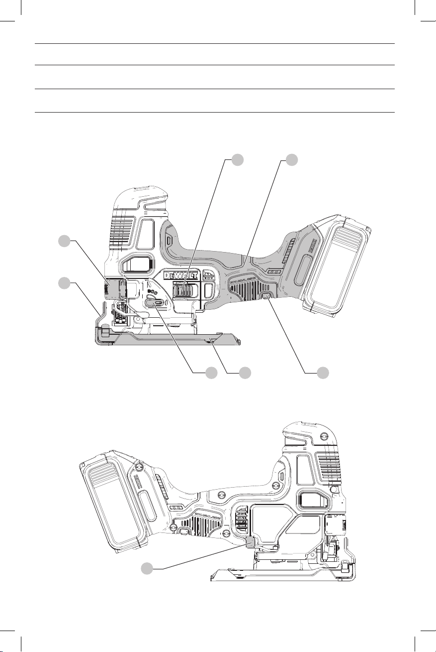
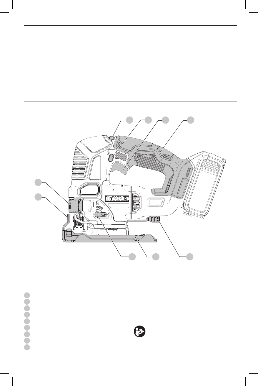
1
Variable speed trigger (DCS334), On/Off switch (DCS335)
2
Lock-off button (DCS334 only)
3
Speed control dial
4
Blade release latch
5
Finger guard
6
Orbital action lever
7
Shoe
8
Shoe bevel lever
9
Handle
6 87
WARNING: Read all safety warnings and all
instructions. Failure to follow the warnings and
instructions may result in electric shock, fire and/or
seriousinjury.
WARNING: To reduce the risk of injury, read the
instructionmanual.
If you have any questions or comments about this or
any
1-800-4-
tool, call us toll free at:
(1-800-433-9258).
1
Page 4

ENGLISH
GENERAL POWER TOOL SAFETY WARNINGS
WARNING! Read all safety warnings and all
instructions. Failure to follow the warnings and
instructions may result in electric shock, fire and/or
seriousinjury.
SAVE ALL WARNINGS AND
INSTRUCTIONS FOR FUTURE
REFERENCE
The term “power tool” in the warnings refers to your mainsoperated (corded) power tool or battery-operated (cordless)
powertool.
1) Work Area Safety
a ) Keep work area clean and well lit. Cluttered or dark
areas inviteaccidents.
b ) Do not operate power tools in explosive
atmospheres, such as in the presence of
flammable liquids, gases or dust. Power tools
create sparks which may ignite the dust orfumes.
c ) Keep children and bystanders away while
operating a power tool. Distractions can cause you
to losecontrol.
2) Electrical Safety
a ) Power tool plugs must match the outlet. Never
modify the plug in any way. Do not use any
adapter plugs with earthed (grounded) power
tools. Unmodified plugs and matching outlets will
reduce risk of electricshock.
b ) Avoid body contact with earthed or grounded
surfaces such as pipes, radiators, ranges and
refrigerators. There is an increased risk of electric
shock if your body is earthed orgrounded.
c ) Do not expose power tools to rain or wet
conditions. Water entering a power tool will increase
the risk of electricshock.
d ) Do not abuse the cord. Never use the cord for
carrying, pulling or unplugging the power tool.
Keep cord away from heat, oil, sharp edges or
moving parts. Damaged or entangled cords increase
the risk of electricshock.
e ) When operating a power tool outdoors, use an
extension cord suitable for outdoor use. Use of
a cord suitable for outdoor use reduces the risk of
electricshock.
f ) If operating a power tool in a damp location
is unavoidable, use a ground fault circuit
interrupter (GFCI) protected supply. Use of a GFCI
reduces the risk of electricshock.
3) Personal Safety
a ) Stay alert, watch what you are doing and use
common sense when operating a power tool. Do
not use a power tool while you are tired or under
the influence of drugs, alcohol or medication. A
moment of inattention while operating power tools
may result in serious personalinjury.
b ) Use personal protective equipment. Always wear
eye protection. Protective equipment such as dust
mask, non-skid safety shoes, hard hat, or hearing
2
protection used for appropriate conditions will reduce
personalinjuries.
c ) Prevent unintentional starting. Ensure the
switch is in the off-position before connecting
to power source and/or battery pack, picking up
or carrying the tool. Carrying power tools with your
finger on the switch or energizing power tools that
have the switch on invitesaccidents.
d ) Remove any adjusting key or wrench before
turning the power tool on. A wrench or a key left
attached to a rotating part of the power tool may
result in personalinjury.
e ) Do not overreach. Keep proper footing and
balance at all times. This enables better control of
the power tool in unexpectedsituations.
f ) Dress properly. Do not wear loose clothing or
jewelry. Keep your hair, clothing and gloves
away from moving parts. Loose clothes, jewelry or
long hair can be caught in movingparts.
g ) If devices are provided for the connection of dust
extraction and collection facilities, ensure these
are connected and properly used. Use of dust
collection can reduce dust-relatedhazards.
h ) Do not let familiarity gained from frequent use
of tools allow you to become complacent and
ignore tool safety principles. A careless action can
cause severe injury within a fraction of asecond.
4) Power Tool Use and Care
a ) Do not force the power tool. Use the correct
power tool for your application. The correct power
tool will do the job better and safer at the rate for
which it wasdesigned.
b ) Do not use the power tool if the switch does not
turn it on and off. Any power tool that cannot be
controlled with the switch is dangerous and must
berepaired.
c ) Disconnect the plug from the power source and/
or the battery pack, if detachable, from the
power tool before making any adjustments,
changing accessories, or storing power tools.
Such preventive safety measures reduce the risk of
starting the power toolaccidentally.
d ) Store idle power tools out of the reach of children
and do not allow persons unfamiliar with the
power tool or these instructions to operate the
power tool. Power tools are dangerous in the hands
of untrainedusers.
e ) Maintain power tools. Check for misalignment or
binding of moving parts, breakage of parts and
any other condition that may affect the power
tool’s operation. If damaged, have the power
tool repaired before use. Many accidents are
caused by poorly maintained powertools.
f ) Keep cutting tools sharp and clean. Properly
maintained cutting tools with sharp cutting edges are
less likely to bind and are easier tocontrol.
g ) Use the power tool, accessories and tool bits, etc.
in accordance with these instructions, taking
into account the working conditions and the
Page 5

work to be performed. Use of the power tool for
operations different from those intended could result
in a hazardoussituation.
h ) Keep handles and grasping surfaces dry, clean
and free from oil and grease. Slippery handles and
grasping surfaces do not allow for safe handling and
control of the tool in unexpectedsituations.
5) Battery Tool Use and Care
a ) Recharge only with the charger specified by the
manufacturer. A charger that is suitable for one type
of battery pack may create a risk of fire when used
with another batterypack.
b ) Use power tools only with specifically designated
battery packs. Use of any other battery packs may
create a risk of injury andfire.
c ) When battery pack is not in use, keep it away
from other metal objects, like paper clips, coins,
keys, nails, screws, or other small metal objects,
that can make a connection from one terminal to
another. Shorting the battery terminals together may
cause burns or afire.
d ) Under abusive conditions, liquid may be ejected
from the battery; avoid contact. If contact
accidentally occurs, flush with water. If liquid
contacts eyes, additionally seek medical help.
Liquid ejected from the battery may cause irritation
orburns.
e ) Do not use a battery pack or tool that is
damaged or modified. Damaged or modified
batteries may exhibit unpredictable behavior resulting
in fire, explosion or risk ofinjury.
f ) Do not expose a battery pack or tool to fire
or excessive temperature. Exposure to fire or
temperature above 130 °C may causeexplosion.
g ) Follow all charging instructions and do not
charge the battery pack or tool outside the
temperature range specified in the instructions.
Charging improperly or at temperatures outside the
specified range may damage the battery and increase
the risk offire.
6) Service
a ) Have your power tool serviced by a qualified
repair person using only identical replacement
parts. This will ensure that the safety of the power
tool ismaintained.
b ) Never service damaged battery packs. Service
of battery packs should only be performed by the
manufacturer or authorized serviceproviders.
Additional Specific Safety Rules for
Jig Saws
• Hold power tool by insulated gripping surfaces,
when performing an operation where the cutting
accessory may contact hidden wiring. Cutting
accessory contacting a “live” wire may make exposed
metal parts of the power tool “live” and could give the
operator an electricshock.
ENGLISH
• Use clamps or another practical way to secure and
support the workpiece to a stable platform. Holding
the work by hand or against your body leaves it unstable
and may lead to loss ofcontrol.
• Allow the motor to come to a complete stop before
withdrawing the blade from the kerf (the slot
created by cutting). A moving blade may impact the
workpiece causing a broken blade, workpiece damage or
loss of control and possible personalinjury.
• Keep handles dry, clean, free from oil and grease.
This will enable better control of thetool.
• Keep blades sharp. Dull blades may cause the saw to
swerve or stall underpressure.
• Clean out your tool often, especially after heavy
use. Dust and grit containing metal particles often
accumulate on interior surfaces and could create an
electric shockhazard.
• Do not operate this tool for long periods of time.
Vibration caused by the operating action of this tool may
cause permanent injury to fingers, hands, and arms. Use
gloves to provide extra cushion, take frequent rest periods,
and limit daily time ofuse.
Additional Safety Information
WARNING: ALWAYS use safety glasses. Everyday
eyeglasses are NOT safety glasses. Also use face or
dust mask if cutting operation is dusty. ALWAYS WEAR
CERTIFIED SAFETYEQUIPMENT:
• ANSI Z87.1 eye protection (CAN/CSA Z94.3),
• ANSI S12.6 (S3.19) hearing protection,
• NIOSH/OSHA/MSHA respiratoryprotection.
WARNING: Some dust created by power sanding,
sawing, grinding, drilling, and other construction
activities contains chemicals known to the State
of California to cause cancer, birth defects or
other reproductive harm. Some examples of these
chemicalsare:
• lead from lead-based paints,
• crystalline silica from bricks and cement and other
masonry products, and
• arsenic and chromium from chemicallytreatedlumber.
Your risk from these exposures varies, depending on how
often you do this type of work. To reduce your exposure to
these chemicals: work in a well ventilated area, and work with
approved safety equipment, such as those dust masks that are
specially designed to filter out microscopicparticles.
• Avoid prolonged contact with dust from power
sanding, sawing, grinding, drilling, and other
construction activities. Wear protective clothing and
wash exposed areas with soap and water. Allowing
dust to get into your mouth, eyes, or lay on the skin may
promote absorption of harmfulchemicals.
WARNING: Use of this tool can generate and/
or disperse dust, which may cause serious and
permanent respiratory or other injury. Always use
NIOSH/OSHA approved respiratory protection
3
Page 6

ENGLISH
DeWALT
DeWALT
appropriate for the dust exposure. Direct particles
away from face andbody.
WARNING: Always wear proper personal hearing
protection that conforms to ANSI S12.6 (S3.19)
during use. Under some conditions and duration
of use, noise from this product may contribute to
hearingloss.
• Air vents often cover moving parts and should be
avoided. Loose clothes, jewelry or long hair can be
caught in movingparts.
The label on your tool may include the following symbols. The
symbols and their definitions are asfollows:
V ......................... volts
Hz ....................... hertz
min ..................... minutes
or DC ......direct current
...................... Class I Construction
(grounded)
…/min .............. per minute
BPM .................... beats per minute
IPM ..................... impacts per minute
RPM .................... revolutions per
minute
sfpm ................... surface feet per
minute
SPM .................... strokes per minute
A ......................... amperes
W ........................ watts
or AC ........... alternating current
or AC/DC .... alternating or
direct current
...................... Class II
Construction
(double insulated)
no ....................... no load speed
n ......................... rated speed
...................... earthing terminal
..................... safety alert symbol
..................... visible radiation
..................... wear respiratory
protection
..................... wear eye
protection
..................... wear hearing
protection
..................... read all
documentation
BATTERIES AND CHARGERS
The battery pack is not fully charged out of the carton.
Before using the battery pack and charger, read the
safety instructions below and then follow charging
proceduresoutlined. When ordering replacement battery
packs, be sure to include the catalog number andvoltage.
Your tool uses a
instructions before using your charger. Consult the chart
at the end of this manual for compatibility of chargers and
batterypacks.
charger. Be sure to read all safety
READ ALL INSTRUCTIONS
Important Safety Instructions for All
Battery Packs
WARNING: Read all safety warnings and all
instructions for the battery pack, charger and
power tool. Failure to follow the warnings and
instructions may result in electric shock, fire and/
or seriousinjury.
• Do not charge or use the battery pack in explosive
atmospheres, such as in the presence of flammable
liquids, gases or dust. Inserting or removing the battery
pack from the charger may ignite the dust orfumes.
• NEVER force the battery pack into the charger. DO
NOT modify the battery pack in any way to fit into
a non-compatible charger as battery pack may
4
rupture causing serious personal injury. Consult
the chart at the end of this manual for compatibility of
batteries andchargers.
• Charge the battery packs only in designated
• DO NOT splash or immerse in water or otherliquids.
• Do not store or use the tool and battery pack in
• Do not incinerate the battery pack even if it is
• If battery contents come into contact with the skin,
• Contents of opened battery cells may cause
chargers.
locations where the temperature may reach or
exceed 104°F (40°C) (such as outside sheds or metal
buildings in summer). For best life store battery packs in
a cool, drylocation.
NOTE: Do not store the battery packs in a tool with
the trigger switch locked on. Never tape the trigger
switch in the ONposition.
severely damaged or is completely worn out. The
battery pack can explode in a fire. Toxic fumes and
materials are created when lithium ion battery packs
areburned.
immedicately wash area with mild soap and water.
If battery liquid gets into the eye, rinse water over the open
eye for 15 minutes or until irritation ceases. If medical
attention is needed, the battery electrolyte is composed of
a mixture of liquid organic carbonates and lithiumsalts.
respiratory irritation. Provide fresh air. If symptoms
persist, seek medicalattention.
WARNING: Burn hazard. Battery liquid may be
flammable if exposed to spark orflame.
WARNING: Fire hazard. Never attempt to open the
battery pack for any reason. If the battery pack case
is cracked or damaged, do not insert into the charger.
Do not crush, drop or damage the battery pack. Do
not use a battery pack or charger that has received a
sharp blow, been dropped, run over or damaged in
any way (e.g., pierced with a nail, hit with a hammer,
stepped on). Damaged battery packs should be
returned to the service center forrecycling.
Transportation
WARNING: Fire hazard. Do not store or carry the
battery pack so that metal objects can contact
exposed battery terminals. For example, do
not place the battery pack in aprons, pockets, tool
boxes, product kit boxes, drawers, etc., with loose
nails, screws, keys, etc. Transporting batteries
can possibly cause fires if the battery terminals
inadvertently come in contact with conductive
materials such as keys, coins, hand tools and the
like. The US Department of Transportation Hazardous
Material Regulations (HMR) actually prohibit
transporting batteries in commerce or on airplanes in
carry-on baggage UNLESS they are properly protected
from short circuits. So when transporting individual
battery packs, make sure that the battery terminals
are protected and well insulated from materials that
could contact them and cause a shortcircuit.
NOTE: Lithium-ion batteries should not be put in
checkedbaggage.
Page 7
Shipping the
DeWALT
e
e
DeWALT
DeWALT
DeWALT
DeWALT
DeWALT
DeWALT
The D
WALT FLEXVOLT™ battery has two modes: Use and
Shipping.
Use Mode: When the FLEXVOLT™ battery stands alone or is
in a D
WALT 20V Max* product, it will operate as a 20V Max*
battery. When the FLEXVOLT™ battery is in a 60V Max* or a
120V Max* (two 60V Max* batteries) product, it will operate
as a 60V Max* battery.
Shipping Mode: When
the cap is attached to the
FLEXVOLT™ battery, the
battery is in Shipping Mode.
Strings of cells are electrically
disconnected within the pack resulting in three batteries
with a lower Watt hour (Wh) rating as compared to one
battery with a higher Watt hour rating. This increased
quantity of three batteries with the lower Watt hour rating
can exempt the pack from certain shipping regulations that
are imposed upon the higher Watt hourbatteries.
The battery label indicates two Watt hour ratings (see
example). Depending on how the battery is shipped, the
appropriate Watt hour rating must be used to determine
the applicable shipping requirements. If utilizing the
shipping cap, the pack will be considered 3 batteries at
the Watt hour rating indicated for “Shipping”. If shipping
without the cap or in a tool, the pack will be considered one
battery at the Watt hour rating indicated next to “Use”.
Example of Use and Shipping Label Marking
For example, Shipping Wh rating might indicate 3 x 40 Wh,
meaning 3 batteries of 40 Watt hours each. The Use Wh
rating might indicate 120 Wh (1 battery implied).
FLEXVOLT™ Battery
USE: 120 Wh Shipping: 3 x 40 Wh
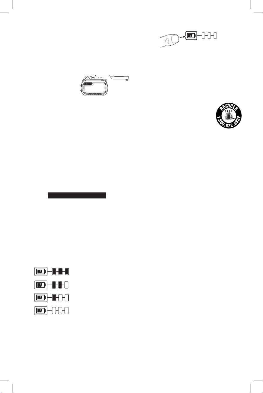
Fuel Gauge Battery Packs (Fig. B)
Some
consists of three green LED lights that indicate the level of
charge remaining in the batterypack.
The fuel gauge is an indication of approximate levels of
charge remaining in the battery pack according to the
followingindicators:
To actuate the fuel gauge, press and hold the fuel gauge
button. A combination of the three green LED lights will
illuminate designating the level of charge left. When the
level of charge in the battery is below the usable limit, the
fuel gauge will not illuminate and the battery will need to
berecharged.
battery packs include a fuel gauge which
75–100% charged
51–74% charged
< 50% charged
Pack needs to be charged
ENGLISH
Fig. B
NOTE: The fuel gauge is only an indication of the charge left
on the battery pack. It does not indicate tool functionality
and is subject to variation based on product components,
temperature and end-userapplication.
For more information regarding fuel gauge battery packs,
please call 1-800-4website www.dewalt.com.
(1-800-433-9258) or visit our
The RBRC® Seal
The RBRC® (Rechargeable Battery
Recycling Corporation) Seal on the nickel
cadmium, nickel metal hydride or lithiumion batteries (or battery packs) indicates
that the costs to recycle these batteries
(or battery packs) at the end of their useful life have already
been paid by
spent nickel cadmium, nickel metal hydride or lithium-ion
batteries in the trash or municipal solid waste stream and
the Call2Recycle® program provides an environmentally
consciousalternative.
Call 2 Recycle, Inc., in cooperation with
battery users, has established the program in the United
States and Canada to facilitate the collection of spent nickel
cadmium, nickel metal hydride or lithium-ion batteries. Help
protect our environment and conserve natural resources by
returning the spent nickel cadmium, nickel metal hydride
or lithium-ion batteries to an authorized
center or to your local retailer for recycling. You may also
contact your local recycling center for information on
where to drop off the spent battery. RBRC® is a registered
trademark of Call 2 Recycle,Inc.
. In some areas, it is illegal to place
and other
service
Important Safety Instructions for All
Battery Chargers
WARNING: Read all safety warnings and all
instructions for the battery pack, charger and
power tool. Failure to follow the warnings and
instructions may result in electric shock, fire and/
or seriousinjury.
• DO NOT attempt to charge the battery pack with
any chargers other than the ones in this manual.
The charger and battery pack are specifically designed to
worktogether.
• These chargers are not intended for any uses other
than charging
Any other uses may result in risk of fire, electric shock
orelectrocution.
• Do not expose the charger to rain orsnow.
• Pull by the plug rather than the cord when
disconnecting the charger. This will reduce the risk of
damage to the electric plug andcord.
• Make sure that the cord is located so that it will not
be stepped on, tripped over or otherwise subjected
to damage orstress.
rechargeable batteries.
5
Page 8
ENGLISH
DeWALT
• Do not use an extension cord unless it is absolutely
necessary. Use of improper extension cord could result in
risk of fire, electric shock orelectrocution.
• When operating a charger outdoors, always provide
a dry location and use an extension cord suitable
for outdoor use. Use of a cord suitable for outdoor use
reduces the risk of electricshock.
• An extension cord must have adequate wire size
(AWG or American Wire Gauge) for safety. The smaller
the gauge number of the wire, the greater the capacity
of the cable, that is, 16 gauge has more capacity than 18
gauge. An undersized cord will cause a drop in line voltage
resulting in loss of power and overheating. When using
more than one extension to make up the total length,
be sure each individual extension contains at least the
minimum wire size. The following table shows the correct
size to use depending on cord length and nameplate
ampere rating. If in doubt, use the next heavier gauge. The
lower the gauge number, the heavier thecord.
Minimum Gauge for Cord Sets
Volts
120 V 25 (7.6) 50 (15.2) 100 (30.5) 150 (45.7)
240 V 50 (15.2) 100 (30.5) 200 (61.0) 300 (91.4)
Ampere Rating
More
Not
Than
More
Than
0 6 18 16 16 14
6 10 18 16 14 12
10 12 16 16 14 12
12 16 14 12 Not Recommended
• Do not place any object on top of the charger or
place the charger on a soft surface that might block
the ventilation slots and result in excessive internal
heat. Place the charger in a position away from any heat
source. The charger is ventilated through slots in the top
and the bottom of thehousing.
• Do not operate the charger with a damaged cord
orplug.
• Do not operate the charger if it has received a sharp
blow, been dropped or otherwise damaged in any
way. Take it to an authorized servicecenter.
• Do not disassemble the charger; take it to an
authorized service center when service or repair
is required. Incorrect reassembly may result in a risk of
electric shock, electrocution orfire.
• Disconnect the charger from the outlet before
attempting any cleaning. This will reduce the risk of
electric shock. Removing the battery pack will not reduce
thisrisk.
• NEVER attempt to connect 2 chargerstogether.
• The charger is designed to operate on standard
120V household electrical power. Do not attempt to
use it on any other voltage. This does not apply to the
vehicularcharger.
WARNING: Shock hazard. Do not allow any liquid to
get inside the charger. Electric shock mayresult.
Total Length of Cord in Feet
(meters)
American Wire Gauge
WARNING: Burn hazard. Do not submerge the
battery pack in any liquid or allow any liquid to
enter the battery pack. Never attempt to open the
battery pack for any reason. If the plastic housing of
the battery pack breaks or cracks, return to a service
center forrecycling.
CAUTION: Burn hazard. To reduce the risk of injury,
charge only
Other types of batteries may overheat and burst
resulting in personal injury and propertydamage.
NOTICE: Under certain conditions, with the charger
plugged into the power supply, the charger can
be shorted by foreign material. Foreign materials
of a conductive nature, such as, but not limited to,
grinding dust, metal chips, steel wool, aluminum
foil or any buildup of metallic particles should be
kept away from the charger cavities. Always unplug
the charger from the power supply when there is no
battery pack in the cavity. Unplug the charger before
attempting toclean.
rechargeable battery packs.
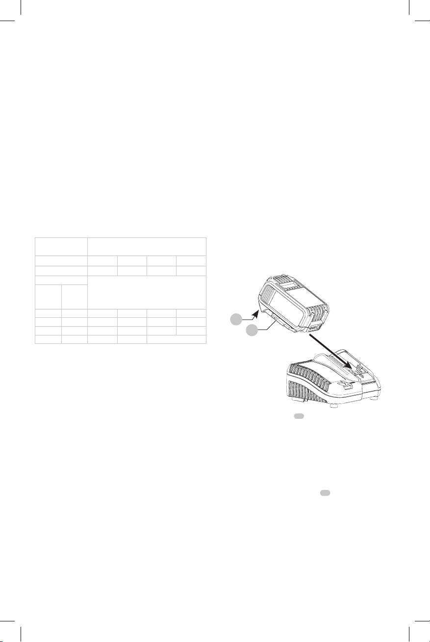
Charging a Battery (Fig. C)
1. Plug the charger into an appropriate outlet before
inserting batterypack.
Fig. C
11
10
2. Insert the battery pack
the battery pack is fully seated in the charger. The red
(charging) light will blink continuously indicating that
the charging process hasstarted.
3. The completion of charge will be indicated by the red
light remaining ON continuously. The battery pack is
fully charged and may be used at this time or left in the
charger. To remove the battery pack from the charger,
push the battery release button
NOTE: To ensure maximum performance and life of lithiumion battery packs, charge the battery pack fully before
firstuse.
Charger Operation
Refer to the indicators below for the charge status of the
batterypack.
10
into the charger, making sure
11
on the batterypack.
6
Page 9

DCB107, DCB112, DCB113, DCB115, DCB118, DCB132
Charging
Fully Charged
Hot/Cold Pack Delay*
* DCB107, DCB112, DCB113, DCB115, DCB118, DCB132:
The red light will continue to blink, but a yellow indicator
light will be illuminated during this operation. Once the
battery pack has reached an appropriate temperature, the
yellow light will turn off and the charger will resume the
chargingprocedure.
The compatible charger(s) will not charge a faulty battery
pack. The charger will indicate faulty battery pack by
refusing tolight.
NOTE: This could also mean a problem with acharger.
If the charger indicates a problem, take the charger and
battery pack to be tested at an authorized servicecenter.
Hot/Cold Pack Delay
When the charger detects a battery pack that is too hot
or too cold, it automatically starts a Hot/Cold Pack Delay,
suspending charging until the battery pack has reached an
appropriate temperature. The charger then automatically
switches to the pack charging mode. This feature ensures
maximum battery packlife.
A cold battery pack will charge at a slower rate than a warm
battery pack. The battery pack will charge at that slower rate
throughout the entire charging cycle and will not return to
maximum charge rate even if the battery packwarms.
The DCB118 charger is equipped with an internal fan
designed to cool the battery pack. The fan will turn on
automatically when the battery pack needs to becooled.
Never operate the charger if the fan does not operate
properly or if ventilation slots are blocked. Do not permit
foreign objects to enter the interior of thecharger.
Electronic Protection System
Li-Ion tools are designed with an Electronic Protection
System that will protect the battery pack against
overloading, overheating or deepdischarge.
The tool will automatically turn off if the Electronic
Protection System engages. If this occurs, place the lithiumion battery pack on the charger until it is fullycharged.
Wall Mounting
DCB107, DCB112, DCB113, DCB115, DCB118, DCB132
These chargers are designed to be wall mountable or to
sit upright on a table or work surface. If wall mounting,
locate the charger within reach of an electrical outlet,
and away from a corner or other obstructions which may
impede air flow. Use the back of the charger as a template
for the location of the mounting screws on the wall. Mount
the charger securely using drywall screws (purchased
separately) at least 1" (25.4 mm) long, with a screw head
diameter of 0.28–0.35" (7–9mm), screwed into wood to an
optimal depth leaving approximately 7/32" (5.5 mm) of the
screw exposed. Align the slots on the back of the charger
with the exposed screws and fully engage them in theslots.
ENGLISH
Charger Cleaning Instructions
WARNING: Shock hazard. Disconnect the charger
from the AC outlet before cleaning. Dirt and grease
may be removed from the exterior of the charger using
a cloth or soft non-metallic brush. Do not use water or
any cleaningsolutions.
Important Charging Notes
1. Longest life and best performance can be obtained if
the battery pack is charged when the air temperature is
between 65°F and 75°F (18° – 24°C). DO NOT charge
the battery pack below +40°F (+4.5°C), or above
+104°F (+40°C). This is important and will prevent
serious damage to the batterypack.
2. The charger and battery pack may become warm to the
touch while charging. This is a normal condition, and
does not indicate a problem. To facilitate the cooling of
the battery pack after use, avoid placing the charger or
battery pack in a warm environment such as in a metal
shed or an uninsulatedtrailer.
3. If the battery pack does not charge properly:
a. Check operation of receptacle by plugging in a lamp
or other appliance;
b. Check to see if receptacle is connected to a light
switch which turns power off when you turn out the
lights;
c. Move the charger and battery pack to a location
where the surrounding air temperature is
approximately 65°F – 75°F (18° – 24°C);
d. If charging problems persist, take the tool, battery
pack and charger to your local servicecenter.
4. The battery pack should be recharged when it fails to
produce sufficient power on jobs which were easily
done previously. DO NOT CONTINUE to use under these
conditions. Follow the charging procedure. You may
also charge a partially used pack whenever you desire
with no adverse effect on the batterypack.
5. Foreign materials of a conductive nature such as, but
not limited to, grinding dust, metal chips, steel wool,
aluminum foil, or any buildup of metallic particles
should be kept away from charger cavities. Always
unplug the charger from the power supply when there
is no battery pack in the cavity. Unplug the charger
before attempting toclean.
6. Do not freeze or immerse the charger in water or any
otherliquid.
Storage Recommendations
1. The best storage place is one that is cool and dry, away
from direct sunlight and excess heat orcold.
2. For long storage, it is recommended to store a fully
charged battery pack in a cool dry place out of the
charger for optimalresults.
NOTE: Battery packs should not be stored completely
depleted of charge. The battery pack will need to be
recharged beforeuse.
7
Page 10
ENGLISH
SAVE THESE INSTRUCTIONS FOR
FUTURE USE
COMPONENTS (FIG. A)
WARNING: Never modify the power tool or any part
of it. Damage or personal injury couldresult.
Refer to Figure A at the beginning of this manual for a
complete list ofcomponents.
Intended Use
The DCS334 and DCS335 jig saws are designed for
professional cutting of wood, steel, aluminium, plastic and
ceramicmaterial.
DO NOT use under wet conditions or in presence of
flammable liquids orgases.
These jig saws are professional power tools. DO NOT let
children come into contact with the tool. Supervision is
required when inexperienced operators use thistool.
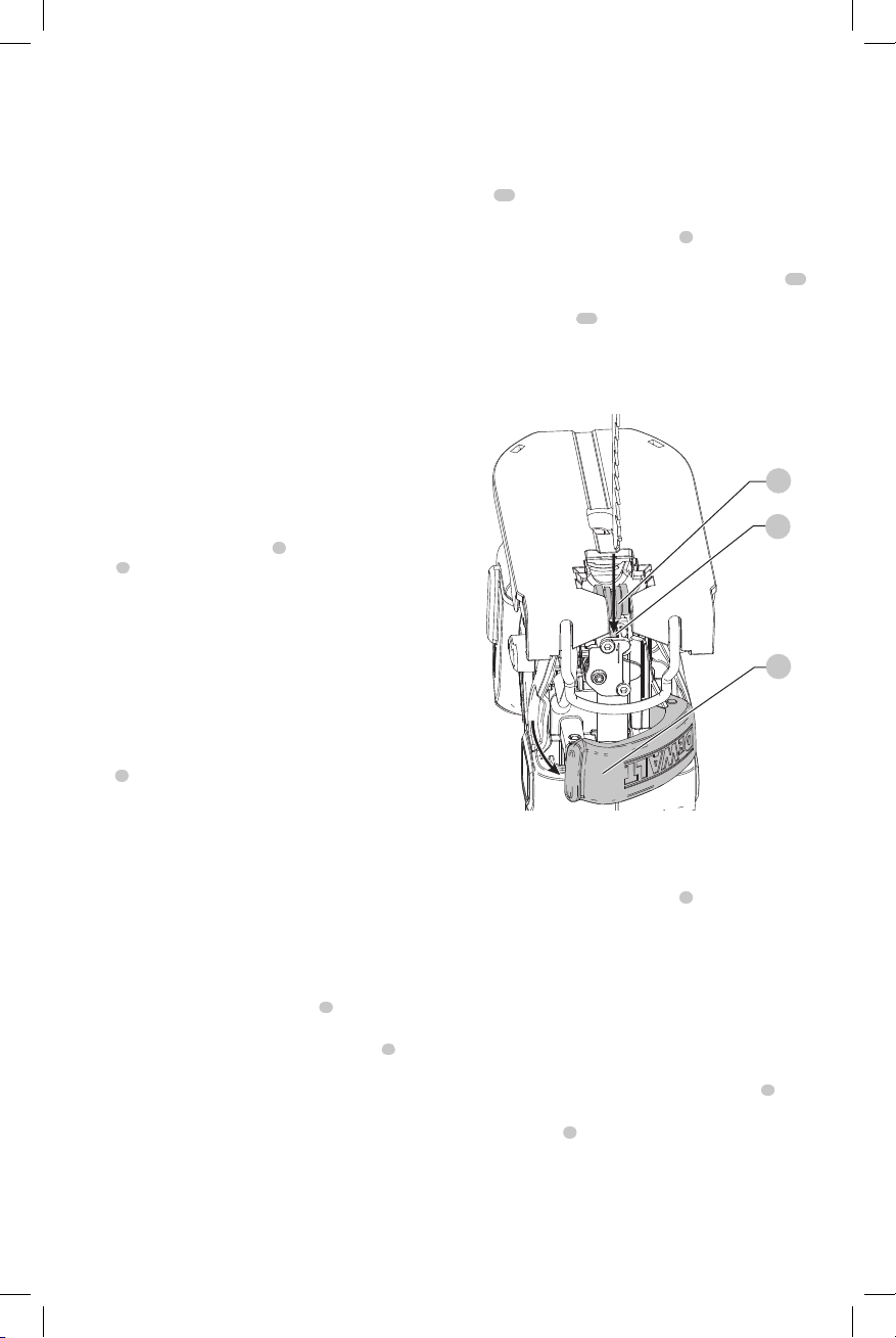
Blade Installation and Removal (Fig. D, J)
To Install a Blade
NOTE: These jig saws use only T-shank jig sawblades.
NOTE: When installing flush cutting blades, the anti-splinter
19
insert (
be in the 0° positive stopposition.
, Fig. J) must be removed and the shoe must to
1. Hold open the blade release latch
FigureD.
2. Insert the T-shank blade into the clamp mechanism
while guiding the back of the blade into the groove of
the guide rollers
3. The T-shank should be completely inside the
clampmechanism.
4. Release the blade releaselatch.
Fig. D
13
.
4
as shown in
12
Lock-Off Button and Variable Speed
Trigger (Fig. A)
DCS334
To lock the variable speed trigger
2
button
. When the lock-off button is depressed to the lock
icon, the unit islocked.
Always lock the trigger switch when carrying or storing the
tool to eliminate unintentionalstarting.
To unlock the trigger switch, press the lock-off button.
When the lock-off button is depressed to the unlock icon,
the unit isunlocked.
NOTE: The lock-off button is colored red to indicate when
the switch is in its unlockedposition.
To start the DCS334 jig saw, squeeze the variable speed
1
trigger
.
To slow and stop the jig saw, release thetrigger.
As the trigger is pressed in, the strokes-per-minute continue
to increase up to the maximum speed of the tool. As the
trigger is released, the blade strokes-per-minutereduce.
NOTE: This tool has no provision to lock the switch in
the ON position, and should never be locked ON by any
othermeans.
1
, press the lock-off
On/Off Switch (Fig. A)
DCS335
CAUTION: Move the on/off switch
position before inserting the batterypack.
To start the DCS335 jig saw, move the on/off switch
the ON position. To turn the jig saw off, move the on/off
switch to the OFFposition.
1
to the OFF
1
to
ASSEMBLY AND ADJUSTMENTS
WARNING: To reduce the risk of serious personal
injury, turn unit off and remove the battery pack
before making any adjustments or removing/
installing attachments or accessories. An
accidental start-up can causeinjury.
8
13
12
4
To Remove a Blade
CAUTION: Do not touch used blades, they may be
hot. Personal injury mayresult.
1. Hold open the blade release latch
2. With a slight shake the blade will dropout.
3. Release the blade releaselatch.
5
.
Beveling the Shoe (Fig. E)
To Bevel the Shoe
1. Remove the dust extraction accessories if they are
mounted to the tool as the tool will not bevel if they are
attached. Refer to Dust Extractionsection.
2. Unlock the shoe by pulling the shoe bevel lever
theside.
3. Slide the shoe
positive stopposition.
NOTE: The shoe can be beveled to the left or to the
right to a maximum of 45° in either direction. There are
visible detents at 15° and 30°.
4. Once the desired bevel angle is achieved, lock the shoe
in position:
7
forward to release it from the 0°
8
to
Page 11
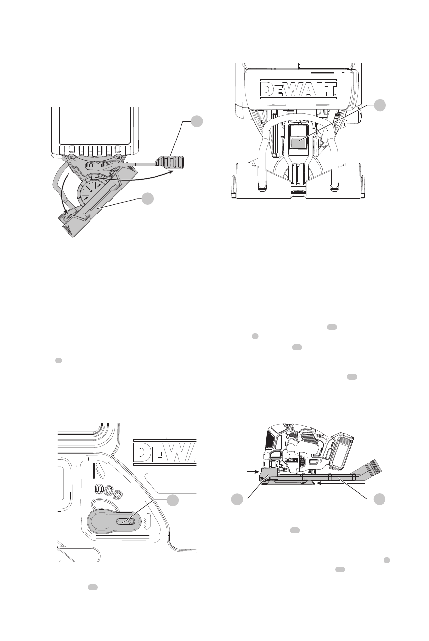
a. For 0° and 45° bevel angles, slide the shoe back and
DeWALT
DeWALT
DeWALT
lock the shoe by moving the shoe bevel lever back
under the body of the jig saw.
b. For all angles between 0° and 45°, lock with bevel
leveronly.
Fig. E
8
7
Cutting Action—Orbital or Straight (Fig. F)
This jig saw is equipped with four cutting actions, three
orbital and one straight. Orbital action has a more
aggressive blade motion and is designed for cutting in soft
materials like wood or plastic. Orbital action provides a faster
cut, but with a less smooth cut across the material. In orbital
action, the blade moves forward during the cutting stroke in
addition to the up and downmotion.
NOTE: Metal or hardwoods should never be cut in
orbitalaction.
To adjust the cutting action, move the orbital action
6
lever
between the four cutting positions: 0, 1, 2, and 3.
Position 0 is straight cutting. Positions 1, 2, and 3 are orbital
cutting. The aggressiveness of the cut increases as the lever
is adjusted from one to three, with three being the most
aggressivecut.
Fig. F
Fig. G
Dust Extraction (Fig. A, H)
Optional Accessory
NOTE: Recommended accessories for use with your tool
are available at extra cost from an authorized
servicecenter.
The dust extraction chute in combination with the
dust extraction shroud helps extract dust from the
workpiece surface, when connected to a suitable dust
extractionsystem.
NOTE: The tool will not bevel if the dust extraction
accessories are attached to thetool.
1. Place the dust extraction shroud
5
guard
(Fig. A) until it clicks intoplace.
2. Slide the dust chute
it snaps into the dust shroud. Be sure the adapter end
is facingup.
3. To connect a vacuum to the dust chute
quick connector (DWV9000), found on all full
size
port, and twist the collar to lock it intoplace.
Fig. H
15
vacuum hoses, over the dust collection
14
onto the finger
from the back of the tool until
15
, place a
ENGLISH
18
Dust Blower (Fig. G)
The dust blower
created from theblade.
18
helps clear the cutting area of debris
6
14
15
Removeable No-Mar Shoe Cover (Fig. I)
The no-mar shoe cover
surfaces that scratch easily, such as laminate, veneer
orpaint.
To attach no-mar shoe cover, place the front of the shoe
into the front of the no-mar shoe cover
jig saw. The no-mar shoe will click securely onto the rear of
theshoe.
16
should be used when cutting
16
and lower the
7
9
Page 12
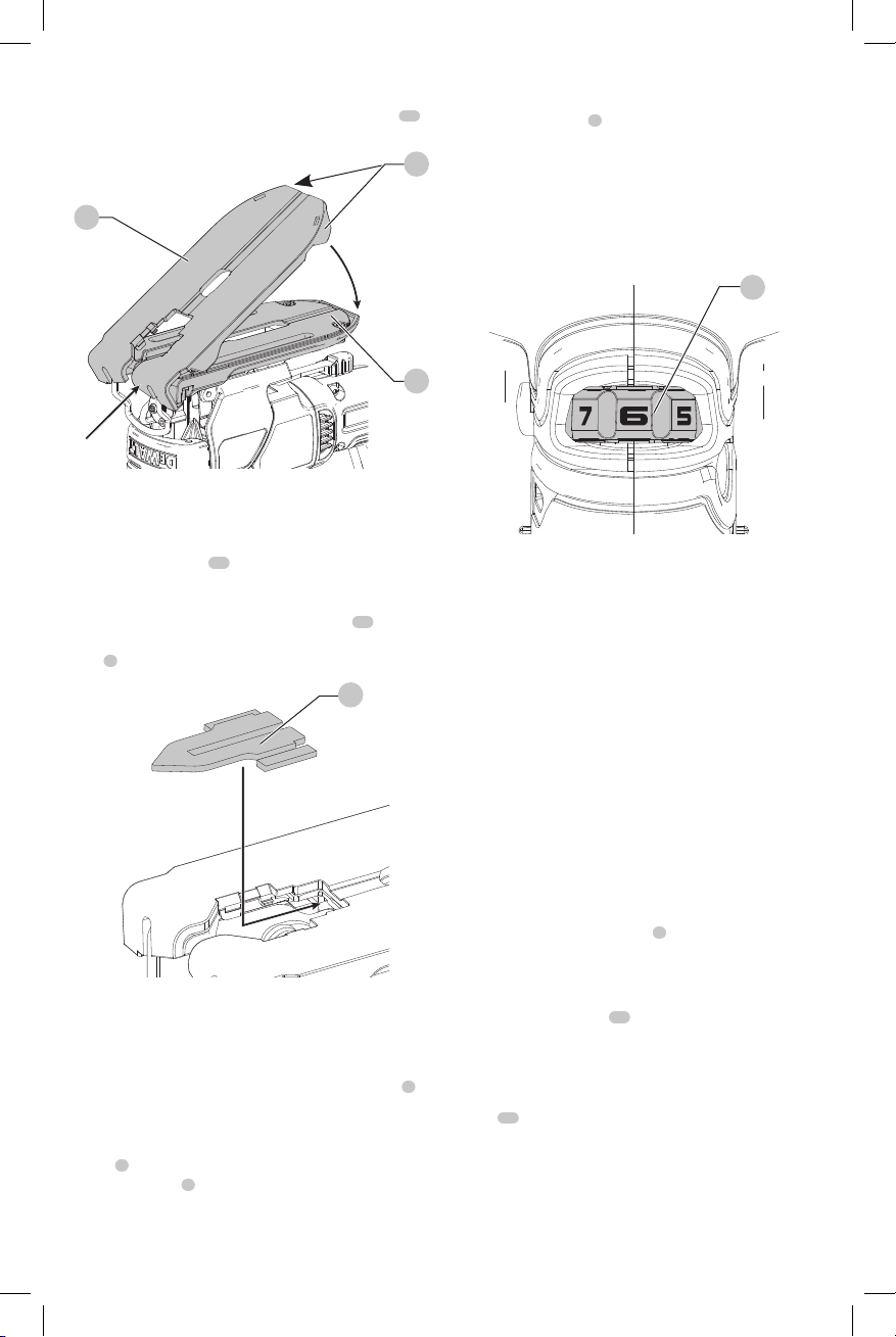
ENGLISH
To remove no-mar shoe cover, grasp the no-mar shoe
cover from the bottom; holding onto the two rear tabs
remove the no-mar shoecover.
Fig. I
16
17
17
7
Anti-Splinter Insert (Fig. A, I, J)
NOTE: Do not use the anti-splinter insert with the flush
cuttingblade.
The anti-splinter insert
minimize tear-out, especially when cutting veneer, laminate,
or finished surfaces, such as paint. The anti-splinter insert
should be installed into the no-mar shoe cover
no-mar cover is not used, install anti-splinter insert into
7
shoe
.
Fig. J
19
should be used when trying to
16
19
. If the
DCS335
The speed control dial
the required range ofspeed.
1. Turn the electronic control dial to the required level.
The DCS335 will turn on at that speed when the on/off
switch is moved to the ON position. The required setting
depends on the thickness and kind ofmaterial.
NOTE: Use high speeds for sawing soft materials such
aswood.
Fig. K
3
can be used for advance setting of
Worklights
The worklights are located on either side of the blade.
To turn on the worklight, depress the trigger (DCS334)
or switch on the on/off switch (DCS335). Worklights will
remain on 20 seconds after the trigger is released or the on/
off switch is moved to the off position.
NOTE: The worklights are for lighting the immediate work
surface and are not intended to be used as a flashlight.
3
Setting the Electronic Sawing Speed
(Fig. A, K)
DCS334
To preset the sawing speed, turn the speed control dial
to the desired level. The higher the number on the speed
control dial, the higher the sawing speed. The sawing speed
varies with the pressure exerted on the variable speed
1
, but will not exceed the speed that is set by the
trigger
speed control dial
thickness and kind ofmaterial.
NOTE: Use high speeds for sawing soft materials such
aswood.
10
3
. The required setting depends on the
3
OPERATION
WARNING: To reduce the risk of serious personal
injury, turn unit off and remove the battery pack
before making any adjustments or removing/
installing attachments or accessories. An
accidental start-up can causeinjury.
Installing and Removing the Battery Pack
(Fig. A, L)
DCS335: Move the on/off switch
before inserting the batterypack.
NOTE: For best results, make sure your battery pack is
fullycharged.
To install the battery pack
battery pack with the rails inside the tool’s handle and slide
it into the handle until the battery pack is firmly seated in
the tool and ensure that it does notdisengage.
To remove the battery pack from the tool, press the release
11
button
handle. Insert it into the charger as described in the charger
section of thismanual.
and firmly pull the battery pack out of the tool
1
to the OFF position
10
into the tool handle, align the
Page 13
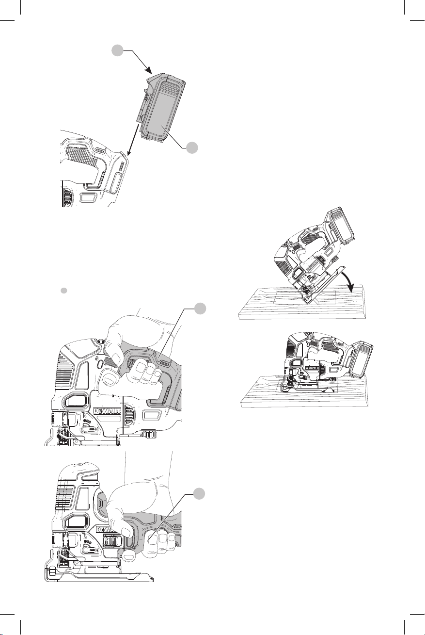
Fig. L
11
Proper Hand Position (Fig. M)
WARNING: To reduce the risk of serious personal injury,
ALWAYS use proper hand position as shown.
WARNING: To reduce the risk of serious personal
injury, ALWAYS hold securely in anticipation of a
suddenreaction.
Proper hand position requires one hand on the main
9
handle
.
Fig. M
ENGLISH
Cutting
WARNING: The jig saw should not be operated with
the shoe removed or serious personal injury mayresult.
Pocket Cutting (Fig. N)
A pocket cut is an easy method of making an inside cut.
The saw can be inserted directly into a panel or board
without first drilling a lead or pilot hole by following these
instructions. In pocket cutting, measure the surface to be
cut and mark clearly with a pencil. Next tip the saw forward
10
until the front end of the shoe sits firmly on the work surface
and the blade clears the work through its full stroke. Switch
the tool on and allow it to attain maximum speed. Grip the
saw firmly and lower the back edge of tool slowly until the
blade reaches its complete depth. Hold the shoe flat against
the wood and begin cutting. Do not remove blade from cut
while it is still moving. Blade must come to a completestop.
Fig. N
9
DCS334
DCS335
Flush Cutting
A flush cut is necessary when finishing off cuts up to a wall
or an obstacle, such as back-splash. One of the easiest ways
to accomplish the flush cut is to use a flush cutting blade.
The flush cutting blade provides the reach necessary to cut
right up to the front edge of the jig saw shoe. Remove the
anti-splinter insert and return the shoe to the 0° positive
stop position before installing and using the flush cutting
9
blade. For the best cut quality the flush cutting blade should
be used in the 0 or 1 orbital position. The flush cutting blade
should not be used to start the cut because the flush cutting
blade prevents the shoe from being supported by the work
surface. Use wood cutting practices explainedbelow.
Wood Cutting
Support the workpiece adequately at all times. Use the
higher speed setting for cutting wood. Do not attempt to
turn the tool on when blade is against material to be cut.
This could stall the motor. Place the front of shoe on the
material to be cut and hold the jig saw shoe firmly against
11
Page 14

ENGLISH
DeWALT
DeWALT
DeWALT
DeWALT
DeWALT
DeWALT
DeWALT
DeWALT
DeWALT
DeWALT
DeWALT
DeWALT
the wood while cutting. Don’t force the tool; let the blade
cut at its own speed. When the cut is complete, turn the jig
saw off. Let blade come to a complete stop and then lay the
saw aside before loosening thework.
Metal Cutting
In cutting thin gauge sheet metals, it is best to clamp wood
to the bottom of sheet metal; this will insure a clean cut
without the risk of vibration or tearing of metal. Always
remember to use a finer blade for ferrous metals (for those
that have a high iron content); and use a coarser blade for
non-ferrous metals (those that do not have an iron content).
Use a high speed setting for cutting soft metals (aluminum,
copper, brass, mild steel, galvanized pipe, conduit, sheet
metal, etc.). Use lower speed to cut plastics, tile, laminate,
hard metals, and castiron.
MAINTENANCE
WARNING: To reduce the risk of serious personal
injury, turn unit off and remove the battery pack
before making any adjustments or removing/
installing attachments or accessories. An
accidental start-up can causeinjury.
Cleaning
WARNING: Blow dirt and dust out of all air vents with
clean, dry air at least once a week. To minimize the risk
of eye injury, always wear ANSI Z87.1 approved eye
protection when performingthis.
WARNING: Never use solvents or other harsh
chemicals for cleaning the non-metallic parts of
the tool. These chemicals may weaken the plastic
materials used in these parts. Use a cloth dampened
only with water and mild soap. Never let any liquid
get inside the tool; never immerse any part of the tool
into aliquid.
Accessories
WARNING: Since accessories, other than those
offered by
product, use of such accessories with this tool could be
hazardous. To reduce the risk of injury, only
recommended accessories should be used with
thisproduct.
Recommended accessories for use with your tool
are available at extra cost from your local dealer or
authorized service center. If you need assistance in
locating any accessory, please contact
Tool Co., 701East Joppa Road, Towson, MD 21286, call
1-800-4www.dewalt.com.
, have not been tested with this
(1-800-433-9258) or visit our website:
Industrial
Repairs
The charger and battery pack are notserviceable.
WARNING: To assure product SAFETY and
RELIABILITY, repairs, maintenance and adjustment
(including brush inspection and replacement, when
applicable) should be performed by a
service center or a
Always use identical replacementparts.
12
authorized service center.
factory
Register Online
Thank you for your purchase. Register your product nowfor:
• WARRANTY SERVICE: Registering your product will
help you obtain more efficient warranty service in case
there is a problem with yourproduct.
• CONFIRMATION OF OWNERSHIP: In case of
an insurance loss, such as fire, flood or theft, your
registration of ownership will serve as your proof
ofpurchase.
• FOR YOUR SAFETY: Registering your product will
allow us to contact you in the unlikely event a safety
notification is required under the Federal Consumer
SafetyAct.
Register online at www.dewalt.com/register.
Three Year Limited Warranty
will repair, without charge, any defects due to
faulty materials or workmanship for three years from
the date of purchase. This warranty does not cover part
failure due to normal wear or tool abuse. For further detail
of warranty coverage and warranty repair information,
visit www.dewalt.com or call 1-800-4433-9258). This warranty does not apply to accessories
or damage caused where repairs have been made
or attempted by others. THIS LIMITED WARRANTY IS
GIVEN IN LIEU OF ALL OTHERS, INCLUDING THE IMPLIED
WARRANTY OF MERCHANTABILITY AND FITNESS FOR A
PARTICULAR PURPOSE, AND EXCLUDES ALL INCIDENTAL
OR CONSEQUENTIAL DAMAGES. Some states do not allow
limitations on how long an implied warranty lasts or the
exclusion or limitation of incidental or consequential
damages, so these limitations may not apply to you. This
warranty gives you specific legal rights and you may have
other rights which vary in certain states orprovinces.
In addition to the warranty,
byour:
1 YEAR FREE SERVICE
will maintain the tool and replace worn parts
caused by normal use, for free, any time during the first year
afterpurchase.
2 YEARS FREE SERVICE ON DEWALT BATTERY PACKS
DC9071, DC9091, DC9096, DC9182, DC9280, DC9360, DCB120,
DCB127, DCB201, DCB203BT, DCB207, DCB361
3 YEARS FREE SERVICE ON DEWALT BATTERY PACKS
DCB200, DCB204, DCB204BT, DCB203, DCB205, DCB205BT,
NOTE: Battery warranty voided if the battery pack is
tampered with in any way.
for any injury caused by tampering and may prosecute
warranty fraud to the fullest extent permitted bylaw.
If you are not completely satisfied with the performance of
your
can return it within 90 days from the date of purchase with
a receipt for a full refund – no questionsasked.
DCB206, DCB230, DCB606, DCB609
90 DAY MONEY BACK GUARANTEE
Power Tool, Laser, or Nailer for any reason, you
tools are covered
is not responsible
(1-800-
Page 15

LATIN AMERICA: This warranty does not apply to products
DeWALT
sold in Latin America. For products sold in Latin America,
see country specific warranty information contained in
the packaging, call the local company or see website for
warrantyinformation.
FREE WARNING LABEL REPLACEMENT: If your warning
labels become illegible or are missing, call 1-800-4(1-800-433-9258) for a freereplacement.
ENGLISH
13
Page 16

FRANÇAIS
DeWALT
DeWALT
Définitions : symboles et termes d'alarmes sécurité
Ces guides d'utilisation utilisent les symboles et termes d'alarmes sécurité suivants pour vous prévenir de situations
dangereuses et de risques de dommages corporels ou matériels.
DANGER: indique une situation dangereuse imminente qui, si elle n’est pas évitée, entraînera la mort ou des
blessuresgraves.
AVERTISSEMENT: indique une situation potentiellement dangereuse qui, si elle n’est pas évitée, pourrait entraîner la
mort ou des blessuresgraves.
ATTENTION: indique une situation potentiellement dangereuse qui, si elle n’est pas évitée, pourrait entraîner des
blessures légères oumodérées.
(Si utilisé sans aucun terme) Indique un message propre à la sécurité.
AVIS : indique une pratique ne posant aucun risque de dommages corporels mais qui par contre, si rien n’est fait
pour l’éviter, pourrait poser des risques de dommages matériels.
Fig. A
123 9
4
5
DCS334
1
Gâchette de vitesse variable (DCS334), Bouton marche/
arrêt (DCS335)
2
Bouton de verrouillage (DCS334 seulement)
3
Cadran de réglage de la vitesse
4
Verrou de déblocage
5
Protège-doigts
6
Levier de l’action orbitale
7
Patin
8
Levier du patin en biseau
9
Poignée
14
6 87
AVERTISSEMENT : lire tous les avertissements
de sécurité et toutes les directives. Le non-respect
des avertissements et des directives pourrait se
solder par un choc électrique, un incendie et/ou une
blessuregrave.
AVERTISSEMENT : afin de réduire le risque de
blessures, lire le mode d’emploi del’outil.
Pour toute question ou remarque au sujet de cet outil
ou de tout autre outil
sans frais : 1-800-4-
, composez le numéro
(1-800-433-9258).
Page 17

Fig. A
FRANÇAIS
1 9
4
5
DCS335
6 7
3
8
15
Page 18

FRANÇAIS
AVERTISSEMENTS DE SÉCURITÉ GÉNÉRAUX
POUR LES OUTILS ÉLECTRIQUES
AVERTISSEMENT! lire tous les avertissements de
sécurité et toutes les directives. Le non-respect
des avertissements et des directives pourrait se
solder par un choc électrique, un incendie et/ou une
blessuregrave.
CONSERVER TOUS LES
AVERTISSEMENTS ET TOUTES
LES DIRECTIVES POUR UN USAGE
ULTÉRIEUR
Le terme « outil électrique » cité dans les avertissements se
rapporte à votre outil électrique à alimentation sur secteur
(avec fil) ou par piles (sans fil).
1) Sécurité du lieu de travail
a ) Tenir l’aire de travail propre et bien éclairée.
Les lieux encombrés ou sombres sont propices
auxaccidents.
b ) Ne pas faire fonctionner d’outils électriques
dans un milieu déflagrant, tel qu’en présence de
liquides, de gaz ou de poussières inflammables.
Les outils électriques produisent des étincelles qui
pourraient enflammer la poussière ou lesvapeurs.
c ) Éloigner les enfants et les personnes à proximité
pendant l’utilisation d’un outil électrique. Une
distraction pourrait en faire perdre la maîtrise à
l’utilisateur.
2) Sécurité en matière d’électricité
a ) Les fiches des outils électriques doivent
correspondre à la prise. Ne jamais modifier la
fiche d’aucune façon. Ne jamais utiliser de fiche
d’adaptation avec un outil électrique mis à la
terre. Le risque de choc électrique sera réduit par
l’utilisation de fiches non modifiées correspondant à
laprise.
b ) Éviter tout contact physique avec des surfaces
mises à la terre comme des tuyaux, des
radiateurs, des cuisinières et des réfrigérateurs.
Le risque de choc électrique est plus élevé si votre corps
est mis à laterre.
c ) Ne pas exposer les outils électriques à la pluie ou
à l’humidité. La pénétration de l’eau dans un outil
électrique augmente le risque de chocélectrique.
d ) Ne pas utiliser le cordon de façon abusive.
Ne jamais utiliser le cordon pour transporter,
tirer ou débrancher un outil électrique. Tenir le
cordon éloigné de la chaleur, de l’huile, des bords
tranchants et des pièces mobiles. Les cordons
endommagés ou enchevêtrés augmentent les risques
de chocélectrique.
e ) Pour l’utilisation d’un outil électrique à
l’extérieur, se servir d’une rallonge convenant à
cette application. L’utilisation d’une rallonge conçue
pour l’extérieur réduira les risques de chocélectrique.
f ) S’il est impossible d’éviter l’utilisation d’un
outil électrique dans un endroit humide,
brancher l’outil dans une prise ou sur un circuit
d’alimentation dotés d’un disjoncteur de fuite à
la terre (GFCI). L’utilisation de ce type de disjoncteur
réduit les risques de chocélectrique.
3) Sécurité personnelle
a ) Être vigilant, surveiller le travail effectué et faire
preuve de jugement lorsqu’un outil électrique
est utilisé. Ne pas utiliser d’outil électrique en
cas de fatigue ou sous l’influence de drogues,
d’alcool ou de médicaments. Un simple moment
d’inattention en utilisant un outil électrique peut
entraîner des blessures corporellesgraves.
b ) Utiliser des équipements de protection
individuelle. Toujours porter une protection
oculaire. L’utilisation d’équipements de protection
comme un masque antipoussière, des chaussures
antidérapantes, un casque de sécurité ou des
protecteurs auditifs lorsque la situation le requiert
réduira les risques de blessurescorporelles.
c ) Empêcher les démarrages intempestifs. S’assurer
que l’interrupteur se trouve à la position
d’arrêt avant de relier l’outil à une source
d’alimentation et/ou d’insérer un bloc-piles, de
ramasser ou de transporter l’outil. Transporter
un outil électrique alors que le doigt repose sur
l’interrupteur ou brancher un outil électrique dont
l’interrupteur est à la position de marche risque de
provoquer unaccident.
d ) Retirer toute clé de réglage ou clé avant de
démarrer l’outil. Une clé ou une clé de réglage
attachée à une partie pivotante de l’outil électrique
peut provoquer des blessurescorporelles.
e ) Ne pas trop tendre les bras. Conserver
son équilibre en tout temps. Cela permet
de mieux maîtriser l’outil électrique dans les
situationsimprévues.
f ) S’habiller de manière appropriée. Ne pas porter
de vêtements amples ni de bijoux. Garder les
cheveux, les vêtements et les gants à l’écart des
pièces mobiles. Les vêtements amples, les bijoux ou
les cheveux longs risquent de rester coincés dans les
piècesmobiles.
g ) Si des composants sont fournis pour le
raccordement de dispositifs de dépoussiérage
et de ramassage, s’assurer que ceux-ci sont bien
raccordés et utilisés. L’utilisation d’un dispositif de
dépoussiérage peut réduire les dangers engendrés par
lespoussières.
h ) Ne pas laisser votre connaissance acquise suite
l’utilisation fréquente des outils vous permettre
de baisser la garde et ignorer les principes de
sécurité de l’outil. Un acte irréfléchi peut causer une
blessure grave en une fraction deseconde.
16
Page 19

4) Utilisation et entretien d’un outil
électrique
a ) Ne pas forcer un outil électrique. Utiliser l’outil
électrique approprié à l’application. L’outil
électrique approprié effectuera un meilleur travail,
de façon plus sûre et à la vitesse pour laquelle il a
étéconçu.
b ) Ne pas utiliser un outil électrique dont
l’interrupteur est défectueux. Tout outil électrique
dont l’interrupteur est défectueux est dangereux et
doit êtreréparé.
c ) Débranchez la fiche de la prise électrique et/
ou, si amovible, retirez le bloc-piles de l’outil
avant d’effectuer tout ajustement, changement
d’accessoires et entreposage des outils
électriques. Ces mesures préventives réduisent les
risques de démarrage accidentel de l’outilélectrique.
d ) Ranger les outils électriques hors de la portée
des enfants et ne permettre à aucune personne
n’étant pas familière avec un outil électrique ou
son mode d’emploi d’utiliser cet outil. Les outils
électriques deviennent dangereux entre les mains
d’utilisateursinexpérimentés.
e ) Entretien des outils électriques. Vérifier si les
pièces mobiles sont mal alignées ou coincées,
si des pièces sont brisées ou présentent toute
autre condition susceptible de nuire au bon
fonctionnement de l’outil électrique. En cas de
dommage, faire réparer l’outil électrique avant
toute nouvelle utilisation. Beaucoup d’accidents
sont causés par des outils électriques malentretenus.
f ) S’assurer que les outils de coupe sont aiguisés et
propres. Les outils de coupe bien entretenus et affûtés
sont moins susceptibles de se coincer et sont plus
faciles àmaîtriser.
g ) Utiliser l’outil électrique, les accessoires, les
forets, etc. conformément aux présentes
directives en tenant compte des conditions de
travail et du travail à effectuer. L’utilisation d’un
outil électrique pour toute opération autre que celle
pour laquelle il a été conçu estdangereuse.
h ) Gardez vos mains et les surfaces d’emprise
sèches, propres et libres de graisse et de
poussière. Les mains et les surfaces de prise glissante
ne permettent pas la manutention et le contrôle
sécuritaires de l’outil dans les situationsimprévues.
5) Utilisation et entretien du bloc-piles
a ) Ne recharger l’outil qu’au moyen du chargeur
précisé par le fabricant. L’utilisation d’un chargeur
qui convient à un type de bloc-piles risque de
provoquer un incendie s’il est utilisé avec un autre type
de b loc-piles.
b ) Utiliser les outils électriques uniquement avec
les blocs-piles conçus à cet effet. L’utilisation de
tout autre bloc-piles risque de causer des blessures ou
unincendie.
FRANÇAIS
c ) Lorsque le bloc-piles n’est pas utilisé, le tenir
éloigné des objets métalliques, notamment
des trombones, de la monnaie, des clés, des
clous, des vis ou autres petits objets métalliques
qui peuvent établir une connexion entre les
deux bornes. Le court-circuit des bornes du bloc-piles
risque de provoquer des brûlures ou unincendie.
d ) En cas d’utilisation abusive, le liquide peut gicler
hors du bloc-piles; éviter tout contact avec ce
liquide. Si un contact accidentel se produit, laver
à grande eau. Si le liquide entre en contact avec
les yeux, obtenir également des soins médicaux.
Le liquide qui gicle hors du bloc-piles peut provoquer
des irritations ou desbrûlures.
e ) Ne pas utiliser un bloc-piles ou un outil qui
est endommagé ou qui a été modifié. Les piles
endommagées ou modifiées peuvent avoir un
comportement imprévisible entraînant un incendie,
une explosion ou un risque deblessure.
f ) Ne pas exposer le bloc-piles ou l’outil au feu ou à
une température excessive. L’exposition au feu ou
à une température au-dessus de 130 °C peut entraîner
uneexplosion.
g ) Suivez les instructions de recharge et ne pas
recharger le bloc-piles ou l’outil hors de la plage
de températures indiquée dans les instructions.
Recharger le bloc-piles de façon inappropriée ou
hors des températures de la plage indiquée pourrait
l’endommager et augmenter le risque d’incendie.
6) Réparation
a ) Faire réparer l’outil électrique par un réparateur
professionnel en n’utilisant que des pièces de
rechange identiques. Cela permettra de maintenir
une utilisation sécuritaire de l’outilélectrique.
b ) Ne jamais réparer de bloc-piles endommagé. La
réparation de blocs-piles doit seulement être effectuée
par le fabricant ou les fournisseurs de serviceautorisé.
Régles de sécurité additionnelles
particuliéres concernant les scies sauteuses
• Tenir l’outil par les surfaces isolées prévues à cet
effet pendant toute utilisation où l’organe de coupe
pourrait entrer en contact avec des fils électriques
cachés. Tout contact de l’organe de coupe avec un fil sous
tension mettra les parties métalliques exposées de l’outil
sous tension et électrocutera l’utilisateur.
• Utilisez des serres de fixation ou un autre dispositif
de fixation permettant de soutenir et de retenir la
pièce sur une plate-forme stable. Tenir la pièce avec la
main ou contre son corps n’est pas suffisamment stable et
risque de provoquer une perte de maîtrise de l’outil.
• Attendre que le moteur s’arrête complètement
avant de retirer la lame de l’entaille (la fente créée
par la coupe). Une lame qui bouge peut rebondir contre
la pièce et se briser ou endommager la pièce ou encore,
faire perdre la maîtrise de l’outil et causer des risques
deblessure.
17
Page 20

FRANÇAIS
DeWALT
• Garder les poignées propres, sèches et exemptes de
toute trace d’huile et de graisse afin d’éviter de perdre
la maîtrise de l’outil.
• Maintenir les lames bien aiguisées, car les lames
usées peuvent faire dévier la scie ou faire caler le moteur
lorsqu’on exerce trop de pression sur l’outil.
• Bien nettoyer l’outil périodiquement, surtout
après l’avoir utilisé longuement, car la poussière et
les particules métalliques tendent à s’accumuler sur les
surfaces internes et peuvent entraîner des risques de
chocélectrique.
• Ne pas utiliser cet outil pendant des périodes
prolongées. Les vibrations causées par l’action de
fonctionnement de l’outil peuvent blesser en permanence
les doigts, les mains et les bras. Porter des gants pour
amortir les vibrations, faire des pauses fréquentes et limiter
le temps d’utilisation quotidien de l’outil.
Consigne de sécurité supplémentaire
AVERTISSEMENT: porter SYSTEMATIQUEMENT
des lunettes de protection. Les lunettes courantes
NE sont PAS des lunettes de protection. Utiliser aussi
un masque antipoussières si la découpe doit en
produire beaucoup. PORTER SYSTÉMATIQUEMENT UN
ÉQUIPEMENT DE SÉCURITÉ HOMOLOGUÉ:
• Protection oculaire ANSI Z87.1 (CAN/CSA Z94.3);
• Protection auditive ANSI S12.6 (S3.19);
• Protection des voies respiratoires NIOSH/OSHA/
MSHA.
AVERTISSEMENT: les scies, meules, ponceuses,
perceuses ou autres outils de construction peuvent
produire des poussières contenant des produits
chimiques reconnus par l’État californien pour causer
cancers, malformations congénitales ou être nocifs au
système reproducteur. Parmi ces produits chimiques,
on retrouve:
• Le plomb dans les peintures à base de plomb;
• La silice cristallisée dans les briques et le ciment,
ou autres produits de maçonnerie; et
• L’arsenic et le chrome dans le bois ayant subi un
traitementchimique.
Le risque associé à de telles expositions varie selon la
fréquence à laquelle on effectue ces travaux. Pour réduire
toute exposition à ces produits: travailler dans un endroit
bien aéré, en utilisant du matériel de sécurité homologué, tel
un masque antipoussières spécialement conçu pour filtrer les
particulesmicroscopiques.
• Limiter toute exposition prolongée avec les
poussières provenant du ponçage, sciage, meulage,
perçage ou toute autre activité de construction.
Porter des vêtements de protection et nettoyer à
l’eau savonneuse les parties du corps exposées. Le
fait de laisser la poussière pénétrer dans la bouche, les
yeux ou la peau peut favoriser l’absorption de produits
chimiquesdangereux.
AVERTISSEMENT: cet outil peut produire et/
ou répandre de la poussière susceptible de causer
des dommages sérieux et permanents au système
18
respiratoire. Utiliser systématiquement un appareil
de protection des voies respiratoires homologué par
le NIOSH ou l’OSHA. Diriger les particules dans le sens
opposé au visage et aucorps.
AVERTISSEMENT: pendant l’utilisation, porter
systématiquement une protection auditive
individuelle adéquate homologuée ANSI S12.6
(S3.19). Sous certaines conditions et suivant la durée
d’utilisation, le bruit émanant de ce produit pourrait
contribuer à une perte de l’acuitéauditive.
• Prendre des précautions à proximité des évents,
car ils cachent des pièces mobiles. Vêtements amples,
bijoux ou cheveux longs risquent de rester coincés dans
ces piècesmobiles.
L’étiquette apposée sur votre outil peut inclure les symboles
suivants. Les symboles et leur définition sont indiqués ci-après:
V ......................... volts
Hz ....................... hertz
min ..................... minutes
or DC ...... courant continu
...................... fabrication classe I
(mis à la terre)
…/min .............. par minute
BPM .................... battements par
minute
IPM ..................... impacts par minute
RPM .................... révolutions par
minute
sfpm ................... pieds linéaires par
minute (plpm)
SPM (FPM) ......... fréquence par
minute
A ......................... ampères
W ........................ watts
or AC ........... courant alternatif
or AC/DC .... courant alternatif
ou continu
...................... fabrication classe II
(double isolation)
no ....................... vitesse à vide
n ......................... vitesse nominale
...................... borne de terre
...................... symbole
d’avertissement
..................... radiation visible
..................... protection
respiratoire
..................... protection oculaire
..................... protection auditive
..................... lire toute la
documentation
BLOCS-PILES ET CHARGEURS
Le bloc-piles n’est pas totalement chargé d’usine. Avant
d’utiliser le bloc-piles et le chargeur, lire les consignes de
sécurité ci-après puis suivre la procédure de chargement
indiquée. Pour commander un bloc-piles de rechange,
s’assurer d’en inclure le numéro de catalogue et latension.
Cet outil fonctionne avec un chargeur
de bien lire toutes les consignes de sécurité avant toute
utilisation du chargeur. Consulter le tableau en fin de
manuel pour connaître les compatibilités entre chargeurs
et blocs-piles.
LIRE TOUTES LES CONSIGNES
. S’assurer
Consignes importantes de sécurité
les blocs-piles
AVERTISSEMENT : lire toutes les instructions et
toutes les consignes de sécurité propres au bloc-
piles, au chargeur et à l’outil électrique. Tout
manquement aux avertissements et instructions
pose des risques de décharges électriques,
d’incendie et/ou de blessures graves.
Page 21

• Ne pas recharger ou utiliser un bloc-piles en milieu
DeWALT
DeWALT
déflagrant, en présence, par exemple, de poussières,
gaz ou liquides inflammables. Le fait d’insérer ou
retirer un bloc-piles de son chargeur pourrait causer
l’inflammation de poussières ou d’émanations.
• NE JAMAIS forcer l’insertion d’un bloc-piles dans un
chargeur. NE modifier un bloc-piles d’AUCUNE façon
pour le faire rentrer dans un chargeur incompatible,
car il pourrait se briser et causer des dommages
corporels graves. Consulter le tableau en dernière page
de ce manuel pour connaître les compatibilités entre
chargeurs et blocs-piles.
• Recharger les blocs-piles exclusivement dans des
chargeurs
• NE PAS éclabousser le bloc-piles ou l’immerger dans l’eau
ou dans tout autreliquide.
• Ne pas entreposer ou utiliser l’appareil et le bloc-
piles en présence de températures ambiantes
pouvant excéder 40°C (104°F) (comme dans des
hangars ou des bâtiments métalliques l’été). Pour
préserver leur durée de vie, entreposer les blocs-piles dans
un endroit frais etsec.
REMARQUE: ne pas mettre un bloc-piles dans un
outil dont la gâchette est verrouillée en position de
marche. Ne jamais bloquer l’interrupteur en position
deMARCHE.
• Ne pas incinérer le bloc-piles même s’il est
sévèrement endommagé ou complètement usagé,
car il pourrait exploser et causer un incendie.
Pendant l’incinération des blocs-piles au lithium-ion, des
vapeurs et matières toxiques sontdégagées.
• En cas de contact du liquide de la pile avec la peau,
rincer immédiatement au savon doux et à l’eau. En
cas de contact oculaire, rincer l’œil ouvert à l’eau claire
une quinzaine de minutes ou jusqu’à ce que l’irritation
cesse. Si des soins médicaux s’avéraient nécessaires, noter
que l’électrolyte de la pile est composé d’un mélange de
carbonates organiques liquides et de sels delithium.
• Le contenu des cellules d’une pile ouverte peut
causer une irritation respiratoire. En cas d’inhalation,
exposer l’individu à l’air libre. Si les symptômes persistent,
consulter unmédecin.
AVERTISSEMENT: risques de brûlure. Le liquide de la
pile peut s’enflammer s’il est exposé à des étincelles ou
à uneflamme.
AVERTISSEMENT: risques d’incendie. Ne jamais
tenter d’ouvrir le bloc-piles pour quelque raison
que ce soit. Si le boîtier du bloc-piles est fissuré ou
endommagé, ne pas l’insérer dans un chargeur. Ne
pas écraser, laisser tomber, ou endommager les blocspiles. Ne pas utiliser un bloc-piles ou un chargeur
qui a reçu un choc violent, ou si l’appareil est tombé,
a été écrasé ou endommagé de quelque façon que
ce soit (p. ex. percé par un clou, frappé d’un coup
de marteau, piétiné). Les blocs-piles endommagés
doivent être renvoyés à un centre de réparation pour
y êtrerecyclés.
.
FRANÇAIS
Transport
AVERTISSEMENT: risques d’incendie. Au moment
de ranger ou transporter le bloc-piles, veiller à
protéger ses bornes à découvert de tout objet
métallique. Par exemple, éviter de placer le bloc-
piles dans un tablier, une poche, une boîte à outils
ou un tiroir, etc. contenant des objets tels que clous,
vis, clés, etc. Le fait de transporter des blocs-piles
comporte des risques d’incendie, car les bornes
des piles pourraient entrer, par inadvertance,
en contact avec des objets conducteurs, tels
que: clés, pièces de monnaie, outils ou autres.
La réglementation sur les produits dangereux
(Hazardous Material Regulations) du département
américain des transports interdit, en fait, le transport
des blocs-piles dans les commerces ou dans les avions
dans les bagages de cabine, À MOINS qu’ils ne soient
correctement protégés de tout court-circuit. Aussi
lors du transport individuel de blocs-piles, s’assurer
que leurs bornes sont bien protégées et isolées de
tout matériau pouvant entrer en contact avec elles et
provoquer un court-circuit.
REMARQUE : il ne faut pas laisser de piles au lithiumion dans les bagagesenregistrés.
Expédition du bloc-piles
Le bloc-piles DeWALT FLEXVOLTMC possède deux modes:
Utilisation et Expédition.
Mode Utilisation: lorsque le bloc-piles FLEXVOLT
lui-même ou dans un produit DeWALT 20V max*, il
fonctionnera comme un bloc-piles de 20V max*. Lorsque le
bloc-piles FLEXVOLTMC est dans un produit de 60V max* ou
120V max* (deux blocs-piles de 60V max*), il fonctionnera
comme un bloc-piles de 60V max*.
Mode Expédition: lorsque
le capuchon est inséré sur
le bloc-piles FLEXVOLT
le bloc-piles est en mode
Expédition. Les modules
de cellules sont électriquement déconnectés du bloc le
faisant correspondre à trois blocs-piles d’un wattheure (Wh)
inférieur comparé à un bloc-piles de wattheure élevé. Ce
passage à trois blocs-piles à un wattheure inférieur peut
permettre au bloc-piles d’être exempté de suivre certaines
directives d’expédition imposées sur les blocs-piles de
wattheuresupérieur.
L’étiquette du bloc-piles donne deux estimations de
wattheures (se reporter à l’exemple). Selon comment le
bloc-piles est expédié, l’estimation appropriée de wattheure
doit être utilisée pour déterminer les modalités d’expédition
lui correspondant. Si le capuchon d’expédition est utilisé,
le bloc-piles sera considéré comme 3 blocs-piles au
wattheure indiqué pour «Expédition». S’il est expédié sans
le capuchon ou dans un outil, le bloc-piles sera considéré
comme un seul bloc-piles au wattheure indiqué à côté de
«Utilisation».
MC
,
Exemple d’étiquetage d’utilisation et d’expédition
USE: 120 Wh Shipping: 3 x 40 Wh
FLEXVOLT
MC
MC
est par
19
Page 22

FRANÇAIS
DeWALT
DeWALT
DeWALT
DeWALT
DeWALT
DeWALT
Par exemple, le Wh de expédition pourra indiquer
3x40Wh, ce qui correspond à 3 blocs-piles de
40wattheures chacun. L’utilisation du Wh pourra indiquer
120Wh (sous-entendu 1bloc-piles).
Témoin de Charge du Bloc-Piles (Fig. B)
Certains blocs-piles
charge qui consiste en trois voyants Del verts indiquant le
niveau de charge du bloc-piles.
Le témoin de charge indique approximativement le niveau
de charge restant dans le bloc-piles en fonction des voyants
suivants:
Pour activer le témoin de charge, maintenez appuyé le
bouton du témoin de charge. Une combinaison des trois
voyants Del verts s’allumera indiquant le niveau de charge.
Lorsque le niveau de charge du bloc-pile atteint la limite
minimale d’utilisation, le témoin de charge reste éteint et le
bloc-piles doit êtrerechargé.
REMARQUE: le témoin de charge ne fait qu’indiquer
le niveau de charge du bloc-piles. Il ne donne aucune
indication quant au fonctionnement de l’outil. Son propre
fonctionnement pourra aussi varier en fonction des
composants produit, de la température et de l’application
d’utilisation.
Pour plus d’informations quant au témoin de charge du
bloc-piles, veuillez appeler le 1-800-4-
9258) ou vous rendre sur notre site www.dewalt.com.
Fig. B
possèdent un témoin de
Chargé de 75 à 100%
Chargé de 51 à 74%
Chargé de < 50%
Le bloc-piles doit être rechargé
Le sceau SRPRC®
Le sceau SRPRC® (Société de recyclage des
piles rechargeables du Canada) apposé
sur une pile au nickel-cadmium, à hydrure
métallique de nickel ou au lithium-ion
(ou un bloc-piles) indique que les coûts
de recyclage de ces derniers en fin d’utilisation ont déjà été
réglés par
ou aux ordures municipales des piles au nickel-cadmium, à
l’hydrure métallique de nickel ou au lithium-ion, est illégale;
le programme de l’Appel à Recycler® constitue donc une
solution pratique etécologique.
Appel à Recycler Canada, Inc., en collaboration avec
programme aux États-Unis et au Canada pour faciliter la
collecte des piles au nickel-cadmium, à l’hydrure métallique
de nickel ou au lithium-ion usagées. Aidez-nous à protéger
l’environnement et à conserver nos ressources naturelles
20
. Dans certaines régions, la mise au rebut
et d’autres utilisateurs de piles, a mis sur pied de
(1-800-433-
en renvoyant les piles au nickel-cadmium, à l’hydrure
métallique de nickel ou au lithium-ion usagées à un centre
de réparation autorisé
qu’elles y soient recyclées. On peut en outre se renseigner
auprès d’un centre de recyclage local pour connaître
d’autres sites lesacceptant.
SRPRC® est une marque déposée de l’Appel à Recycler
Canada,Inc.
ou chez votre détaillant afin
Directives de sécurité importantes
propres à tous les chargeurs de piles
AVERTISSEMENT : lire toutes les instructions et
toutes les consignes de sécurité propres au bloc-
piles, au chargeur et à l’outil électrique. Tout
manquement aux avertissements et instructions
pose des risques de décharges électriques,
d’incendie et/ou de blessures graves.
• NE PAS tenter de charger de bloc-piles avec des
chargeurs autres que ceux décrits dans ce manuel.
Le chargeur et son bloc-piles ont été conçus tout
spécialement pour fonctionnerensemble.
• Ces chargeurs n’ont pas été conçus pour une
utilisation autre que recharger les blocs-piles
rechargeables
comporte des risques d’incendie, de chocs électriques ou
d’électrocution.
• Protéger le chargeur de la pluie ou de laneige.
• Tirer sur la fiche plutôt que sur le cordon pour
débrancher le chargeur. Cela permet de réduire
les risques d’endommager la fiche ou le cordon
d’alimentation.
• S’assurer que le cordon est protégé de manière à
ce que personne ne marche ni ne trébuche dessus,
ou à ce qu’il ne soit ni endommagé ni soumis à
aucunetension.
• N’utiliser une rallonge qu’en cas de nécessité
absolue. L’utilisation d’une rallonge inadéquate
comporte des risques d’incendie, de chocs électriques ou
d’électrocution.
• Pour utiliser un chargeur à l’extérieur, le placer dans
un endroit sec et utiliser une rallonge conçue pour
l’extérieur. L’utilisation d’une rallonge conçue pour
l’extérieur réduit les risques de chocsélectriques.
• Pour la sécurité de l’utilisateur, utiliser une rallonge
de calibre adéquat (AWG, American Wire Gauge
[calibrage américain normalisé des fils électriques]).
Plus le calibre est petit, et plus sa capacité est grande. Un
calibre16, par exemple, a une capacité supérieure à un
calibre18. L’usage d’une rallonge de calibre insuffisant
causera une chute de tension qui entraînera perte de
puissance et surchauffe. Si plus d’une rallonge est utilisée
pour obtenir une certaine longueur, s’assurer que chaque
rallonge présente au moins le calibre de fil minimum. Le
tableau ci-dessous illustre les calibres à utiliser selon la
longueur de rallonge et l’intensité nominale indiquée sur
la plaque signalétique. En cas de doute, utiliser le calibre
suivant. Plus le calibre est petit, plus la rallonge peut
supporter decourant.
. Toute autre utilisation
Page 23

Calibre minimum pour les cordons d'alimentation
DeWALT
Volts
120 V 7,6 (25) 15,2 (50) 30,5 (100) 45,7 (150)
240 V 15,2 (50) 30,5 (100) 61,0 (200) 91,4 (300)
Ampères
Plus que Pas plus
• Ne poser aucun objet sur le chargeur. Ne pas mettre
le chargeur sur une surface molle qui pourrait en
bloquer la ventilation et provoquer une surchauffe
interne. Éloigner le chargeur de toute source de chaleur.
Le chargeur dispose d’orifices d’aération sur le dessus et le
dessous duboîtier.
• Ne pas le faire fonctionner avec un cordon
d’alimentation ou une ficheendommagée.
• Ne pas utiliser le chargeur s’il a reçu un coup,
fait une chute ou a été endommagé de quelque
façon que ce soit. Le ramener dans un centre de
réparationagréé.
• Ne pas démonter le chargeur. Pour tout service
ou réparation, le rapporter dans un centre de
réparation agréé. Le fait de le réassembler de façon
incorrecte comporte des risques de chocs électriques,
d’électrocution et d’incendie.
• Débrancher le chargeur du secteur avant tout
entretien. Cela réduira tout risque de chocs
électriques. Le fait de retirer le bloc-piles ne réduira pas
cesrisques.
• NE JAMAIS tenter de connecter 2 chargeursensemble.
• Le chargeur a été conçu pour être alimenté en
courant électrique domestique standard de 120
volts. Ne pas tenter de l’utiliser avec toute autre
tension. Cela ne s’applique pas aux chargeurs de
postesmobiles.
que
0 6 18 16 16 14
6 10 18 16 14 12
10 12 16 16 14 12
12 16 14 12 Non recommandé
AVERTISSEMENT: risques de chocs électriques. Ne
laisser aucun liquide pénétrer dans le chargeur, des
chocs électriques pourraient enrésulter.
AVERTISSEMENT: risques de brûlure. Ne submerger
le bloc-piles dans aucun liquide et le protéger de toute
infiltration de liquide. Ne jamais tenter d’ouvrir le
bloc-piles pour quelque raison que ce soit. Si le boîtier
plastique du bloc-piles est brisé ou fissuré, le retourner
dans un centre de réparation pour y êtrerecyclé.
ATTENTION: risques de brûlure. Pour réduire tout
risque de dommages corporels, ne recharger que des
blocs-piles rechargeables
de piles pourrait exploser et causer des dommages
corporels etmatériels.
AVIS: sous certaines conditions, lorsque le chargeur
est connecté au bloc d’alimentation, des matériaux
étrangers pourraient court-circuiter le chargeur. Les
corps étrangers conducteurs tels que (mais pas limité
à) poussières de rectification, débris métalliques, laine
Longueur totale du cordon
d'alimentation en mètre (pieds)
AWG
. Tout autre type
FRANÇAIS
d’acier, feuilles d’aluminium, ou toute accumulation
de particules métalliques doivent être maintenus
à distance des orifices du chargeur. Débrancher
systématiquement le chargeur lorsque le bloc-piles
n’y est pas inséré. Débrancher systématiquement le
chargeur avant toutentretien.
Chargement du bloc-piles (Fig. C)
1. Branchez le chargeur dans la prise appropriée avant d’y
insérer le bloc-piles.
Fig. C
11
10
2. Insérer le bloc-piles
assurant qu’il y est correctement calé. Le voyant rouge
(charge) clignotera de façon continue indiquant que le
cycle de chargement acommencé.
3. En fin de charge, le voyant rouge restera ALLUMÉ de
façon continue. Le bloc-piles est alors complètement
rechargé et peut être utilisé ou laissé dans le chargeur.
Pour retirer le bloc-piles du chargeur, appuyez sur le
bouton de libération du bloc-piles
REMARQUE: pour assurer des performances optimales
et une durée de vie maximale des blocs-piles au lithiumion, recharger pleinement le bloc-piles avant toute
utilisationinitiale.
Utilisation du chargeur
Reportez-vous aux indications du tableau ci-dessous pour
consulter le statut de charge du bloc-piles.
DCB107, DCB112, DCB113, DCB115, DCB118, DCB132
Bloc-piles en Cours
de Chargement
Bloc-piles Chargé
Suspension de Charge Contre
le Chaud/Froid*
* DCB107, DCB112, DCB113, DCB115, DCB118, DCB132:
le voyant rouge ne cessera de clignoter, mais un voyant
jaune restera allumé pendant cette opération. Lorsque
le bloc-piles aura repris une température appropriée,
le voyant jaune s’éteindra et le chargeur reprendra sa
procédure decharge.
Le chargeur ne pourront recharger des blocs-piles
défectueux. Le chargeur indiquera qu’un bloc-piles est
défectueux en refusant de s’allumer.
10
dans le chargeur, en vous
11
sur le bloc-piles.
21
Page 24

FRANÇAIS
REMARQUE: cela pourra aussi indiquer un problème avec
lechargeur.
Si le problème provient du chargeur, faites vérifier le
chargeur et le bloc-piles chez un centre de réparationagréé.
Fonction de suspension de charge contre le chaud/
froid
Lorsque le chargeur détecte un bloc-piles trop chaud
ou trop froid, il démarre automatiquement la fonction
de suspension de charge contre le chaud, suspendant
le chargement jusqu’à ce que le bloc-piles ait repris
une température appropriée. Le chargeur ensuite se
remettra automatiquement en mode de chargement.
Cette caractéristique assure aux blocs-piles une durée de
viemaximale.
Un bloc-piles froid se rechargera moins vite qu’un bloc-piles
chaud. Le bloc-piles se rechargera à ce rythme plus lent tout
au cours du cycle de charge et ne retournera pas à sa vitesse
maximale de charge même s’il venait à seréchauffer.
Le chargeur DCB118 est équipé d’un ventilateur interne
destiné à refroidir le bloc-piles. Le ventilateur se mettra
automatiquement en marche chaque fois que le bloc-piles
aura besoin de serefroidir.
N’utilisez jamais le chargeur si le ventilateur ne fonctionne
pas correctement ou si ses fentes d’aération sont bloquées.
Protégez systématiquement l’intérieur du chargeur de tout
objetétranger.
Système de protection électronique
Les appareils au Li-Ion sont équipés d’un système
électronique de protection pour protéger les blocs-piles de
toute surcharge, surchauffe ou fuiteimportante.
L’appareil s’arrêtera automatiquement dès que le système
électronique de protection sera activé. Si c’était le cas,
placez le bloc-piles au lithium-ion sur son chargeur jusqu’à
ce qu’il soit complètementrechargé.
Installation murale
DCB107, DCB112, DCB113, DCB115, DCB118, DCB132
Ces chargeurs ont été conçus pour une installation murale
ou pour être posés sur une table ou une surface de travail.
Pour une fixation murale, installez le chargeur à proximité
d’une prise électrique, et à l’écart de coins ou de toute
autre obstruction au passage de l’air. Utilisez l’arrière du
chargeur pour marquer l’emplacement des vis de montage
sur le mur. Fixez soigneusement le chargeur à l’aide de vis
autoforeuses (vendues séparément) d’au moins 25,4mm
(1po) de long, et de diamètre de tête de 7-9mm (0,280,35po), que vous visserez dans le bois en laissant une
longueur optimale d’environ 5,5mm (7/32po) exposée.
Alignez les orifices à l’arrière du chargeur sur les vis exposées
et insérez à fond ces dernières dans lesorifices.
Instructions d’entretien du chargeur
AVERTISSEMENT: risques de chocs électriques.
Débrancher le chargeur de la prise de courant
alternatif avant tout entretien. Éliminer toute saleté
ou graisse de la surface externe du chargeur à l’aide
d’un chiffon ou d’une brosse non métallique douce.
N’utiliser ni eau ni aucun nettoyantliquide.
22
Remarques importantes concernant le
chargement
1. Pour augmenter la durée de vie du bloc-piles
et optimiser son rendement, le recharger à une
température ambiante de 18° à 24°C (65°F à 75°F).
NE PAS charger lorsque le bloc-piles est en dessous
de +4,5 °C (+40°F) ou au-dessus de +40 °C (+104 °F).
C’est important pour prévenir tout dommage sérieux
au bloc-piles.
2. Le chargeur et son bloc-piles peuvent devenir chauds
au toucher pendant la charge. C’est normal et ne
représente en aucun cas une défaillance du produit.
Pour faciliter le refroidissement du bloc-piles après
utilisation, éviter de laisser le chargeur ou le bloc-piles
dans un local où la température ambiante est élevée
comme dans un hangar métallique ou une remorque
nonisolée.
3. Si le bloc-piles ne se recharge pas correctement:
a. Vérifier le bon fonctionnement de la prise
en y branchant une lampe ou tout autre
appareilélectrique.
b. Vérifier que la prise n’est pas contrôlée par un
interrupteur qui coupe le courant lorsqu’on éteint
leslumières.
c. Déplacer le chargeur et le bloc-piles dans un local où
la température ambiante se trouve entre environ 18°
et 24°C (65°F et 75°F).
d. Si le problème persiste, amener l’outil, le bloc-piles et
son chargeur dans un centre de réparationlocal.
4. Recharger le bloc-piles lorsqu’il ne produit plus assez
de puissance pour effectuer un travail qu’il faisait
facilement auparavant. NE PAS CONTINUER à l’utiliser
dans ces conditions. Suivre la procédure de charge. Si
nécessaire, il est aussi possible de recharger
un bloc-piles partiellement déchargé sans effet nuisible
sur le bloc-piles.
5. Les corps étrangers conducteurs tels que (mais
pas limité à) poussières de rectification, débris
métalliques, laine d’acier, feuilles d’aluminium,
ou toute accumulation de particules métalliques
doivent être maintenus à distance des orifices du
chargeur. Débrancher systématiquement le chargeur
lorsque le bloc-piles n’y est pas inséré. Débrancher
systématiquement le chargeur avant toutentretien.
6. Ne pas congeler ou immerger le chargeur dans l’eau ou
tout autreliquide.
Recommandations de stockage
1. Le lieu idéal de rangement est un lieu frais et sec,
à l’abri de toute lumière solaire directe et de toute
températureexcessive.
2. Pour un stockage prolongé, il est recommandé
d’entreposer le bloc-piles pleinement chargé dans
un lieu frais et sec, hors du chargeur pour optimiser
lesrésultats.
Page 25

REMARQUE: les blocs-piles ne devraient pas être
entreposés complètement déchargés. Il sera nécessaire de
recharger le bloc-piles avantréutilisation.
CONSERVER CES CONSIGNES POUR
UTILISATION ULTÉRIEURE
DESCRIPTION (FIG. A)
AVERTISSEMENT: ne jamais modifier l’outil
électrique ni aucun de ses composants, car il y a
risques de dommages corporels oumatériels.
Reportez-vous en FigureA au début de ce manuel pour
obtenir la liste complète descomposants.
Usage Prévu
Les scies sauteuses DCS334 et DCS335 sont conçues pour
la coupe professionnelle bois, de l’acier, de l’aluminium, du
plastique et de lacéramique.
NE PAS utiliser en conditions mouillées ou en présence de
liquides ou de gazinflammables.
Ces scies sauteuses sont des outils électriques
professionnels. NE PAS laisser les enfants entrer en contact
avec l’outil. Une supervision est requise lorsque des
utilisateurs inexpérimentés se servent cetoutil.
Bouton de verrouillage et gâchette de
vitesse variable (Fig. A)
DCS334
Pour verrouiller la gâchette de vitesse variable
sur le bouton de verrouillage
le bouton de verrouillage vers l’icône de verrouillage, l’outil
estverrouillé.
Verrouillez toujours la gâchette lorsque vous transportez
ou entreposez l’outil afin d’éviter le démarrage
nonintentionnel.
Pour verrouiller la gâchette, appuyez sur le bouton
de verrouillage. Lorsque vous appuyez sur le bouton
de verrouillage vers l’icône de déverrouillage, l’outil
estdéverrouillé.
REMARQUE : le bouton de verrouillage est coloré rouge
pour indiquer que la gâchette est en positiondéverrouillée.
Pour démarrer la scie sauteuse DCS334, appuyez sur la
gâchette de vitesse variable
Pour ralentir et arrêter la scie sauteuse, relâchez lagâchette.
Pendant que vous appuyez sur la gâchette, les coups à la
minute continuent à augmenter jusqu’à la vitesse maximum
de l’outil. Lorsque vous relâchez la gâchette, les coups à
minute de la lameréduisent.
REMARQUE : cet outil n’a aucune disposition pour
verrouiller le bouton en position Marche et il ne doit jamais
être verrouillé à Marche d’aucune autrefaçon.
2
. Lorsque vous appuyez sur
1
.
1
, appuyez
Bouton Marche/Arrêt (Fig. A)
DCS335
ATTENTION: déplacez le bouton Marche/Arrêt
position ARRÊT avant d’insérer le bloc-piles.
Pour démarrer la scie sauteuse DCS335, déplacez le bouton
Marche/Arrêt
1
à la position MARCHE. Pour éteindre
1
en
FRANÇAIS
la scie sauteuse, déplacez le bouton Marche/Arrêt à la
positionARRÊT.
ASSEMBLAGE ET AJUSTEMENTS
AVERTISSEMENT: pour réduire le risque de
blessures graves, éteindre l’outil et retirer le bloc-
piles avant d’effectuer tout réglage et d’enlever
ou d’installer tout accessoire. Un démarrage
accidentel peut provoquer desblessures.
Installation et retrait de la lame (Fig. D, J)
Pour installer une lame
REMARQUE: Ces scies sauteuses utilisent seulement les
lames de scie sauteuse T-shank.
REMARQUE: Lorsque vous installez des lames de coupe
à ras, la plaque anti-éclats (
patin doit être en position d’arrêt 0°positif.
1. Maintenez le verrou de déblocage
comme illustré dans la FigureD.
2. Insérez la lame T-shank dans le mécanisme de
3. La lame T-shank doit être complètement à l’intérieur du
4. Relâchez le verrou de déblocage de lalame.
Pour retirer une lame
1. Maintenez le verrou de déblocage
2. La lame tombera en secouantlégèrement.
3. Relâchez le verrou de déblocage de lalame.
12
fixation
rainure des rouleaux des guides
mécanisme defixation.
Fig. D
tout en guidant l’arrière de la lame dans la
ATTENTION: ne pas toucher les lames utilisées,
elles pourraient être chaudes. Cela peut causer une
blessurecorporelle.
19
, Fig. J) doit être retirée et le
4
de la lame ouvert
13
.
5
de la lameouvert.
13
12
4
23
Page 26

FRANÇAIS
DeWALT
DeWALT
DeWALT
Biseautage du patin (Fig. E)
Pour biseauter le patin
1. Retirez les accessoires de dépoussiérage s’ils
sont installés sur l’outil puisque l’outil ne pourra
pas être biseauté s’ils sont fixés. Consultez la
sectionDépoussiérage.
2. Déverrouillez le patin en tirant le levier du patin en
8
biseau
vers lecôté.
3. Glissez le patin
position d’arrêt 0°positif.
REMARQUE : Le patin peut être biseauté vers la gauche
ou la droite à un maximum de 45° dans une direction ou
l’autre. Il y a des crans visibles à 15° et 30°.
4. Une fois l’angle de biseau désiré atteint, verrouillez le
patin en place:
a. Pour les angles de biseau de 0° et 45°, glissez le patin
vers l’arrière et verrouillez-le en déplaçant le levier du
patin en biseau sous le corps de la scie sauteuse.
b. Pour tous les angles entre 0° et 45°, verrouillez-le
seulement avec levier enbiseau.
Fig. E
7
vers l’avant pour le dégager de la
Fig. F
Chasse-sciure (Fig. G)
Le chasse-sciure
la lame dans la zone decoupe.
Fig. G
18
aide à dégager les débris produits par
6
8
7
Coupe en mode orbital ou coupe droite
(Fig. F)
La scie sauteuse est munie d’un levier qui permet d’effectuer
quatre types de coupes, dont trois en mode orbital et un en
mode de coupe droite. Lors de la coupe en mode orbital,
qui est conçu pour la coupe de matériaux mous tels que
le bois et le plastique, la lame se déplace de façon plus
prononcée. Bien qu’une coupe en mode orbital soit plus
rapide, elle produit une surface plus rugueuse en raison des
mouvements verticaux de la lame lorsqu’elle avance durant
sa course detravail.
REMARQUE : on ne doit jamais utiliser la scie en mode
orbital pour couper le métal ou le boisdur.
Pour régler le mode de coupe, déplacer le levier de mode
6
orbital
sur l’une des quatre positions de coupe: 0, 1, 2,
et 3. La position «0» correspond à une coupe droite. Les
positions1, 2 et 3 correspondent à des coupes en mode
orbital. La coupe sera plus prononcée alors que le levier
passera de un à trois, trois étant lemaximum.
24
18
Dépoussiérage (Fig. A, H)
Accessoire optionnel
REMARQUE : les accessoires recommandés pour une
utilisation avec cet outil sont disponibles à un coût
supplémentaire chez votre dans un centre de services
autorisé.
Le conduit de dépoussiérage combiné à l’anneau de
dépoussiérage aide à extraire la poussière de la surface de
la pièce de travail lorsqu’il est connecté à un système de
dépoussiérageapproprié.
REMARQUE : cet outil ne sera pas biseauté si les
accessoires de dépoussiérage y sontfixés.
1. Placez l’anneau de dépoussiérage
5
doigts
(Fig. A) jusqu’à ce qu’il clique enplace.
2. Glissez le conduit de dépoussiérage
de l’outil jusqu’à s’enclenche dans l’anneau de
dépoussiérage. Assurez-vous que l’extrémité de
l’adaptateur est vers lehaut.
3. Pour connecter un aspirateur au conduit de
dépoussiérage
(DWV9000) de
d’aspirateur
15
, placez un connecteur rapide
situé sur tous les tuyaux
pleine grandeur sur le port
14
sur le protège-
15
de l’arrière
Page 27

d’aspiration de poussière et tournez le collier pour le
verrouiller enplace.
Fig. H
Fig. J
FRANÇAIS
19
14
15
Capot du patin sans marques amovible
(Fig. I)
Le capot du patin sans marques
les surfaces de coupe qui s’égratignent facilement comme le
stratifié, le placage ou lapeinture.
Pour fixer le capot du patin sans marques, placez le
devant du patin
marques
marques cliquera de façon sécuritaire à l’arrière dupatin.
Pour retirer le capot du patin sans marques, saisissez le
capot du patin sans marques; en tenant les deux languettes
arrière
Fig. I
7
dans le devant du capot du patin sans
16
et baissez la scie sauteuse. Le patin sans
17
, retirez le capot du patin sansmarques.
16
16
doit être utilisé lorsque
17
7
Plaque anti-éclats (Fig. A, I, J)
REMARQUE: ne pas utiliser la plaque anti-éclats avec la
lame de coupe àras.
La plaque anti-éclats
tentez de minimiser l’arrachement, particulièrement lors
de la coupe de placage, de stratifié ou de surfaces finies
comme la peinture. La plaque anti-éclats doit être installée
dans le capot du patin sans marques
marques n’est pas utilisé, installez la plaque anti-éclats dans
7
le patin
.
19
doit être utilisée lorsque vous
16
. Si le capot sans
Régler la vitesse de sciage électronique
(Fig. A, K)
DCS334
Pour prérégler la vitesse de sciage, tournez le cadran de
réglage de la vitesse
le cadran de réglage de la vitesse est élevé, plus la vitesse
de sciage sera élevée. La vitesse du sciage varie selon la
pression exercée sur la gâchette de vitesse variable
qui n’excédera pas la vitesse qui est réglée par le cadran
de réglage de la vitesse
l’épaisseur et du type dematériau.
REMARQUE : Utilisez les vitesses élevées pour scier des
matériaux mous comme lebois.
DCS335
Le cadran de réglage de la vitesse
un réglage avancé de la plage de vitessesrequise.
1. Tournez le cadran de réglage électronique au niveau
requis. La scie DCS335 se mettra en marche à cette
vitesse lorsque le bouton Marche/Arrêt est déplacé en
position Marche. Le réglage requis dépend de l’épaisseur
et du type dematériau.
REMARQUE : Utilisez les vitesses élevées pour scier des
matériaux mous comme lebois.
Fig. K
3
au niveau désiré. Plus le nombre sur
1
3
. Le réglage requis dépend de
3
peut être utilisé pour
3
, mais
25
Page 28

FRANÇAIS
Lampes de travail
Les lampes de travail sont situées de chaque côté de la lame.
Pour allumer les lampes de travail, appuyez sur la gâchette
(DCS334) ou sur le bouton Marche/Arrêt (DCS335). Les
lampes de travail demeureront allumées pendant 20
secondes après que vous ayez relâché la gâchette ou que
vous ayez déplacé le bouton Marche/Arrêt en position Arrêt.
REMARQUE : Les lampes de travail sont pour éclairer la
surface de travail immédiate et ne sont pas conçues pour
être utilisées comme une lampe de poche.
UTILISATION
AVERTISSEMENT: pour réduire le risque de
blessures graves, éteindre l’outil et retirer le bloc-
piles avant d’effectuer tout réglage et d’enlever
ou d’installer tout accessoire. Un démarrage
accidentel peut provoquer desblessures.
Installation et retrait du bloc-piles
(Fig. A, L)
DCS335: Déplacez le bouton Marche/Arrêt
Arrêt avant d’insérer le bloc-piles.
REMARQUE: pour des résultats optimums, s’assurer que le
bloc-piles est complètementchargé.
Pour installer le bloc-piles
alignez le bloc-piles sur les rails dans la poignée de l’outil et
faites-le glisser fermement en place puis vérifiez qu’il ne s’en
détacherapas.
Pour retirer le bloc-piles de l’outil, poussez sur le bouton
de libération
la poignée de l’outil. Insérez-le dans son chargeur comme
décrit dans la section appropriée de cemanuel.
11
Fig. L
10
dans la poignée de l’outil,
et tirez fermement le bloc-piles hors de
11
1
en position
SYSTÉMATIQUEMENT l’outil fermement pour
anticiper toute réactionsoudaine.
Une position des mains adéquate nécessite une main sur la
poignée principale
Fig. M
9
.
9
DCS334
9
DCS335
Position correcte des mains (Fig. M)
AVERTISSEMENT: pour réduire tout risque
de dommages corporels graves, adopter
SYSTÉMATIQUEMENT la position des mains illustrée.
AVERTISSEMENT: pour réduire tout risque
de dommages corporels graves, maintenir
26
Coupe
AVERTISSEMENT : ne pas utiliser la scie sauteuse
sans y avoir d’abord installé le patin afin d’éviter les
risques de blessuregrave.
Coupe Interne (Fig. N)
Il s’agit d’une méthode facile d’effectuer une coupe à
10
l’intérieur d’un matériau. La scie peut être directement
insérée dans un panneau ou un morceau de bois sans
avoir à percer tout d’abord un avant-trou ou un trou
pilote en suivant ces instructions. Pour réaliser une coupe
à l’intérieur d’une pièce, mesurer la surface à couper et
inscrire clairement une marque au crayon à l’endroit voulu.
Incliner la scie vers l’avant de manière à ce que le devant
du patin repose fermement sur la surface de travail et que
la lame soit complètement dégagée de la pièce lors de sa
course maximale. Mettre l’outil sous tension et attendre qu’il
atteigne sa vitesse maximale. Le saisir fermement l’outil et
abaisser lentement son bord arrière jusqu’à ce que la lame
atteigne toute sa profondeur. Tenir le patin à plat contre le
matériau et amorcer la coupe. Ne pas retirer la lame de la
ligne de coupe lorsqu’elle bouge encore; on doit attendre
qu’elle s’immobilisecomplètement.
Page 29

Fig. N
DeWALT
DeWALT
DeWALT
DeWALT
DeWALT
DeWALT
Coupe Affleurée (Fig. M)
Ce type de coupe est nécessaire lorsqu’on veut finir une
coupe jusqu’au bord d’un mur ou tout près d’un obstacle,
tel un dos anti-éclaboussement. Un des moyens les plus
faciles d’effectuer une coupe affleurée et d’utiliser une
lame de coupe affleurée puisqu’elle permet à l’utilisateur
d’effectuer une coupe tout près du bord avant du patin de
la scie sauteuse. Retirer le dispositif anti-éclats et remettre
le patin à la position de butée fixe (0°) avant d’installer
et d’utiliser la lame de coupe affleurée. Afin d’obtenir les
meilleurs résultats possibles, on doit régler la lame à la
position « 0 » ou de mode orbital « 1 ». On ne doit pas
utiliser la lame de coupe affleurée pour amorcer la coupe
puisqu’elle ne permet pas de supporter le patin sur la
surface de travail. Utiliser la méthode expliquée ci-dessous
pour couper lebois.
Coupe du Bois
Soutenir adéquatement la pièce en tout temps. Toujours
sélectionner la vitesse maximale pour couper le bois. Ne
pas tenter de mettre l’outil sous tension lorsque la lame est
appuyée contre le matériau à couper afin d’éviter de caler le
moteur. Placer le devant du patin sur le matériau à couper
et tenir fermement le patin contre le matériau lors de la
coupe. Ne pas forcer l’outil; laisser la lame couper à la vitesse
normale. Une fois la coupe terminée, mettre l’outil hors
tension et attendre que la lame s’immobilise complètement.
Déposer ensuite la scie de côté avant de desserrer lapièce.
Coupe du Métal
Lorsqu’on coupe une feuille de tôle mince, il est préférable
de fixer un morceau de bois sous la tôle afin d’assurer une
coupe précise sans risquer de causer des vibrations ou de
déchirer la tôle. Utiliser une lame à dents fines pour couper
les métaux ferreux (c’est-à-dire, ceux contenant du fer) et
une lame à grosses dents pour les métaux non ferreux (ceux
ne contenant aucun fer).
FRANÇAIS
Utiliser une haute vitesse pour couper les alliages doux
(l’aluminium, le cuivre, le laiton, l’acier doux, les tuyaux en
acier galvanisé, conduits de tôle, etc.), et une basse vitesse
pour couper les plastiques, les tuiles, les stratifiés, les métaux
durs et lafonte.
MAINTENANCE
AVERTISSEMENT: pour réduire le risque de
blessures graves, éteindre l’outil et retirer le bloc-
piles avant d’effectuer tout réglage et d’enlever
ou d’installer tout accessoire. Un démarrage
accidentel peut provoquer desblessures.
Nettoyage
AVERTISSEMENT : enlever les saletés et la poussière
hors des évents au moyen d’air comprimé propre et
sec, au moins une fois par semaine. Pour minimiser
le risque de blessure aux yeux, toujours porter une
protection oculaire conforme à la norme ANSI Z87.1
lors dunettoyage.
AVERTISSEMENT : ne jamais utiliser de solvants ni
d’autres produits chimiques puissants pour nettoyer
les pièces non métalliques de l’outil. Ces produits
chimiques peuvent affaiblir les matériaux de plastique
utilisés dans ces pièces. Utiliser un chiffon humecté
uniquement d’eau et de savon doux. Ne jamais laisser
de liquide pénétrer dans l’outil et n’immerger aucune
partie de l’outil dans unliquide.
Accessoires
AVERTISSEMENT : puisque les accessoires autres
que ceux offerts par
avec ce produit, leur utilisation pourrait s’avérer
dangereuse. Pour réduire le risque de blessures, utiliser
exclusivement les accessoires
avec le présentproduit.
Les accessoires recommandés pour cet outil sont vendus
séparément au centre de service de votre région. Pour
obtenir de l’aide concernant l’achat d’un accessoire,
communiquer avec
Joppa Road, Towson, MD 21286 aux États-Unis;
composer le 1 800 433-9258 (1 800 4notre site Web : www.dewalt.com.
n’ont pas été testés
Industrial Tool Co., 701 East
recommandés
) ou visiter
Réparations
Le chargeur et le bloc-piles ne sont pasréparables.
AVERTISSEMENT : pour assurer la SÉCURITÉ et la
FIABILITÉ du produit, les réparations, l’entretien et
les réglages doivent être réalisés (cela comprend
l’inspection et le remplacement du balai, le cas
échéant) par un centre de réparation en usine
ou un centre de réparation agréé
Toujours utiliser des pièces de rechangeidentiques.
.
Registre en ligne
Merci pour votre achat. Enregistrez dès maintenant
votreprodui:
• RÉPARATIONS SOUS GARANTIE: cette carte remplie
vous permettra de vous prévaloir du service de
27
Page 30

FRANÇAIS
DeWALT
DeWALT
DeWALT
DeWALT
DeWALT
DeWALT
DeWALT
DeWALT
DeWALT
réparations sous garantie de façon plus efficace dans le
cas d’un probléme avec leproduit.
• CONFIRMATION DE PROPRIÉTÉ: en cas de perte
provoquée par un incendie, une inondation ou un vol,
cette preuve de propriété vous servira de preuve auprès
de votre compagnie d’assurances.
• SÉCURITÉ: l’enregistrement de votre produit
nous permettra de communiquer avec vous dans
l’éventualité peu probable de l’envoi d’un avis de
sécurité régi par la loi fédérale américaine de la
protection desconsommateurs.
Registre en ligne à www.dewalt.com/register.
Garantie limitée de trois ans
réparera, sans frais, tout produit défectueux
causé par un défaut de matériel ou de fabrication pour
une période de trois ans à compter de la date d’achat.
La présente garantie ne couvre pas les pièces dont la
défectuosité a été causée par une usure normale ou
l’usage abusif de l’outil. Pour obtenir de plus amples
renseignements sur les pièces ou les réparations couvertes
par la présente garantie, visiter le site www.dewalt.
com ou composer le 1 800 433-9258 (1 800 4CETTE GARANTIE LIMITÉE REMPLACE TOUTE AUTRE
GARANTIE, Y COMPRIS TOUTE GARANTIE IMPLICITE DE
QUALITÉ MARCHANDE OU DE CONFORMITÉ À DES FINS
PARTICULIÈRES, ET EXCLUT TOUT DOMMAGE ACCESSOIRE
OU INDIRECT. Certains états n’autorisent aucune limitation
quant à la durée d’une garantie implicite ni aucune
exclusion ou limitation de garantie contre tout préjudice
accessoire ou indirect, aussi il se peut que ces exclusions
ne vous soient pas applicables. Cette garantie confère des
droits légaux particuliers à l’acheteur, mais celui-ci pourrait
aussi bénéficier d’autres droits variant d’un territoire à
l’autre.
En plus de la présente garantie, les outils
couverts par notre :
CONTRAT D’ENTRETIEN GRATUIT D’UNAN
entretiendra l’outil et remplacera les pièces usées
au cours d’une utilisation normale et ce, gratuitement,
pendant une période d’un an à compter de la date d’achat.
CONTRAT D’ENTRETIEN GRATUIT DE DEUX ANS SUR
DC9071, DC9091, DC9096, DC9182, DC9280, DC9360, DCB120,
CONTRAT D’ENTRETIEN GRATUIT DETROIS ANS SUR
DCB200, DCB204, DCB204BT, DCB203, DCB205, DCB205BT,
REMARQUE: La garantie de se produit sera annulée si le
bloc-piles a été altéré de quelque façon que ce soit.
ne peut être tenu responsable de tout dommage corporel
causé par l’altération du produit et pourra poursuivre toute
fraude en matière de garantie dans toute l’étendue permise
par laloi.
LES BLOC-PILES
DCB127, DCB201, DCB203BT, DCB207, DCB361
LESBLOC-PILES
DCB206, DCB230, DCB606, DCB609
sont
GARANTIE DE REMBOURSEMENT DE90JOURS
Si l’acheteur n’est pas entièrement satisfait, pour quelque
raison que ce soit, du rendement de l’outil électrique, du
laser ou de la cloueuse
accompagné d’un reçu, dans les 90 jours à compter de la
date d’achat pour obtenir un remboursement intégral, sans
aucunproblème.
AMÉRIQUE LATINE : cette garantie ne s’applique aux
produits vendus en Amérique latine. Pour ceux-ci, veuillez
consulter les informations relatives à la garantie spécifique
présente dans l’emballage, appeler l’entreprise locale ou
consulter le site Web pour les informations relatives à
cettegarantie.
REMPLACEMENT GRATUIT DES ÉTIQUETTES
D’AVERTISSEMENT : si les étiquettes d’avertissement
deviennent illisibles ou sont manquantes, composer le
1 800 433-9258 (1 800 4remplacementgratuit.
).
, celui-ci peut le retourner,
) pour en obtenir le
28
Page 31

FRANÇAIS
29
Page 32

ESPAÑOL
DeWALT
DeWALT
Definiciones: Símbolos y palabras de alerta de seguridad
Este manual de instrucciones utiliza los siguientes símbolos y palabras de alerta de seguridad para alertarle de situaciones
peligrosas y del riesgo de lesiones corporales o daños materiales.
PELIGRO: Indica una situación de peligro inminente que, si no se evita, provocará la muerte o lesionesgraves.
ADVERTENCIA: Indica una situación de peligro potencial que, si no se evita, podría provocar la muerte o
lesionesgraves.
ATENCIÓN: Indica una situación de peligro potencial que, si no se evita, posiblemente provocaría lesiones leves
omoderadas.
(Utilizado sin palabras) indica un mensaje de seguridad relacionado.
AVISO: Se refiere a una práctica no relacionada a lesiones corporales que de no evitarse puede resultar en daños a
la propiedad.
Fig. A
123 9
4
5
DCS334
1
Gatillo de velocidad variable (DCS334), Interruptor On/
Off (DCS335)
2
Botón de bloqueo de apagado (sólo DCS334)
3
Carátula de control de velocidad
4
Seguro de liberación de cuchilla
5
Protección para dedos
6
Palanca de acción orbital
7
Zapata
8
Palanca de bisel de zapata
9
Manija
30
6 87
ADVERTENCIA: Lea todas las advertencias de
seguridad e instrucciones. El incumplimiento
de las advertencias e instrucciones puede provocar
descargas eléctricas, incendios o lesionesgraves.
ADVERTENCIA: Para reducir el riesgo de lesiones, lea
el manual deinstrucciones.
Si tiene alguna duda o algún comentario sobre ésta
u otra herramienta
gratuito: 1-800-4-
, llámenos al número
(1-800-433-9258).
Page 33

Fig. A
ESPAÑOL
1 9
4
5
DCS335
6 7
3
8
31
Page 34

ESPAÑOL
ADVERTENCIAS GENERALES DE SEGURIDAD
PARA HERRAMIENTAS ELÉCTRICAS
¡ADVERTENCIA! Lea todas las advertencias de
seguridad e instrucciones. El incumplimiento
de las advertencias e instrucciones puede provocar
descargas eléctricas, incendios o lesionesgraves.
CONSERVE TODAS LAS ADVERTENCIAS
E INSTRUCCIONES PARA FUTURAS
CONSULTAS
El término “herramienta eléctrica” incluido en las advertencias
hace referencia a las herramientas eléctricas operadas con
corriente (con cable eléctrico) o a las herramientas eléctricas
operadas con baterías (inalámbricas).
1) Seguridad en el Área de Trabajo
a ) Mantenga el área de trabajo limpia y bien
iluminada. Las áreas abarrotadas y oscuras
propicianaccidentes.
b ) No opere las herramientas eléctricas en
atmósferas explosivas, como ambientes donde
haya polvo, gases o líquidos inflamables. Las
herramientas eléctricas originan chispas que pueden
encender el polvo o losvapores.
c ) Mantenga alejados a los niños y a los
espectadores de la herramienta eléctrica en
funcionamiento. Las distracciones pueden provocar
la pérdida decontrol.
2) Seguridad Eléctrica
a ) Los enchufes de la herramienta eléctrica deben
adaptarse al tomacorriente. Nunca modifique el
enchufe de ninguna manera. No utilice ningún
enchufe adaptador con herramientas eléctricas
con conexión a tierra. Los enchufes no modificados
y que se adaptan a los tomacorrientes reducirán el
riesgo de descargaeléctrica.
b ) Evite el contacto corporal con superficies con
descargas a tierra como, por ejemplo, tuberías,
radiadores, cocinas eléctricas y refrigeradores.
Existe mayor riesgo de descarga eléctrica si su cuerpo
está puesto atierra.
c ) No exponga las herramientas eléctricas a la
lluvia o a condiciones de humedad. Si entra agua
a una herramienta eléctrica, aumentará el riesgo de
descargaeléctrica.
d ) No maltrate el cable. Nunca utilice el cable para
transportar, tirar o desenchufar la herramienta
eléctrica. Mantenga el cable alejado del calor, el
aceite, los bordes filosos y las piezas móviles. Los
cables dañados o enredados aumentan el riesgo de
descargaeléctrica.
e ) Al operar una herramienta eléctrica en el
exterior, utilice un cable prolongador adecuado
para tal uso. Utilice un cable adecuado para
uso en exteriores a fin de reducir el riesgo de
descargaeléctrica.
f ) Si el uso de una herramienta eléctrica en un
lugar húmedo es imposible de evitar, utilice
32
un suministro protegido con un interruptor de
circuito por falla a tierra (GFCI). El uso de un GFCI
reduce el riesgo de descargaseléctricas.
3) Seguridad Personal
a ) Permanezca alerta, controle lo que está
haciendo y utilice el sentido común cuando
emplee una herramienta eléctrica. No utilice
una herramienta eléctrica si está cansado o bajo
el efecto de drogas, alcohol o medicamentos.
Un momento de descuido mientras se opera una
herramienta eléctrica puede provocar lesiones
personalesgraves.
b ) Utilice equipos de protección personal. Siempre
utilice protección para los ojos. En las condiciones
adecuadas, el uso de equipos de protección,
como máscaras para polvo, calzado de seguridad
antideslizante, cascos o protección auditiva, reducirá
las lesionespersonales.
c ) Evite el encendido por accidente. Asegúrese de
que el interruptor esté en la posición de apagado
antes de conectarlo a la fuente de energía
o paquete de baterías, o antes de levantar
o transportar la herramienta. Transportar
herramientas eléctricas con el dedo apoyado en el
interruptor o enchufar herramientas eléctricas con
el interruptor en la posición de encendido puede
propiciaraccidentes.
d ) Retire la clavija de ajuste o la llave de tuercas
antes de encender la herramienta eléctrica. Una
llave de tuercas o una clavija de ajuste que quede
conectada a una pieza giratoria de la herramienta
eléctrica puede provocar lesionespersonales.
e ) No se estire. Conserve el equilibrio y párese
adecuadamente en todo momento. Esto permite
un mejor control de la herramienta eléctrica en
situacionesinesperadas.
f ) Use la vestimenta adecuada. No use ropas
holgadas ni joyas. Mantenga el cabello, la
ropa y los guantes alejados de las piezas en
movimiento. Las ropas holgadas, las joyas o el
cabello largo pueden quedar atrapados en las piezas
enmovimiento.
g ) Si se suministran dispositivos para la conexión
de accesorios con fines de recolección y
extracción de polvo, asegúrese de que estén
conectados y que se utilicen correctamente. El
uso de dispositivos de recolección de polvo puede
reducir los peligros relacionados con elpolvo.
h ) No permita que la familiaridad obtenida a partir
del uso frecuente de herramientas le permitan
volverse descuidado e ignorar los principios
de seguridad de la herramienta. Una acción
descuidada puede causar lesiones severas en una
fracción desegundo.
Page 35

4) Uso y Mantenimiento de la
Herramienta Eléctrica
a ) No fuerce la herramienta eléctrica. Utilice la
herramienta eléctrica correcta para el trabajo
que realizará. Si se la utiliza a la velocidad para la
que fue diseñada, la herramienta eléctrica correcta
permite trabajar mejor y de manera mássegura.
b ) No utilice la herramienta eléctrica si no puede
encenderla o apagarla con el interruptor. Toda
herramienta eléctrica que no pueda ser controlada
mediante el interruptor es peligrosa y deberepararse.
c ) Desconecte el enchufe de la fuente de
alimentación y/o el paquete de batería, si
es desmontable, de la herramienta eléctrica
antes de realizar cualquier ajuste, cambiar
accesorios o almacenar herramientas eléctricas.
Estas medidas de seguridad preventivas reducen
el riesgo de encender la herramienta eléctrica en
formaaccidental.
d ) Guarde la herramienta eléctrica que no esté en
uso fuera del alcance de los niños y no permita
que otras personas no familiarizadas con ella o
con estas instrucciones operen la herramienta.
Las herramientas eléctricas son peligrosas si son
operadas por usuarios nocapacitados.
e ) Realice el mantenimiento de las herramientas
eléctricas. Revise que no haya piezas en
movimiento mal alineadas o trabadas, piezas
rotas o cualquier otra situación que pueda
afectar el funcionamiento de la herramienta
eléctrica. Si encuentra daños, haga reparar
la herramienta eléctrica antes de utilizarla.
Se producen muchos accidentes a causa de
las herramientas eléctricas que carecen de un
mantenimientoadecuado.
f ) Mantenga las herramientas de corte afiladas
y limpias. Las herramientas de corte con
mantenimiento adecuado y con los bordes de corte
afilados son menos propensas a trabarse y son más
fáciles decontrolar.
g ) Utilice la herramienta eléctrica, los accesorios
y las brocas de la herramienta, etc. de acuerdo
con estas instrucciones y teniendo en cuenta
las condiciones de trabajo y el trabajo que debe
realizarse. El uso de la herramienta eléctrica para
operaciones diferentes de aquéllas para las que fue
diseñada podría originar una situaciónpeligrosa.
h ) Mantenga las manijas y superficies de sujeción
secas, limpias y libres de aceite y grasa.
Las manijas y superficies de sujeción resbalosas
no permiten el manejo y control seguros de la
herramienta en situacionesinesperadas.
5) Uso y Mantenimiento de la
Herramienta con Baterías
a ) Recargue solamente con el cargador
especificado por el fabricante. Un cargador
adecuado para un tipo de paquete de baterías puede
ESPAÑOL
originar riesgo de incendio si se utiliza con otro
paquete debaterías.
b ) Utilice herramientas eléctricas sólo con paquetes
de baterías específicamente diseñados. El uso de
cualquier otro paquete de baterías puede producir
riesgo de incendio ylesiones.
c ) Cuando no utilice el paquete de baterías,
manténgalo lejos de otros objetos metálicos
como sujetapapeles, monedas, llaves, clavos,
tornillos u otros objetos metálicos pequeños que
puedan realizar una conexión desde un terminal
al otro. Los cortocircuitos en los terminales de la
batería pueden provocar quemaduras oincendio.
d ) En condiciones abusivas, el líquido puede ser
expulsado de la batería. Evite su contacto. Si
entra en contacto accidentalmente, enjuague
con agua. Si el líquido entra en contacto con los
ojos, busque atención médica. El líquido expulsado
de la batería puede provocar irritación oquemaduras.
e ) No use un paquete de batería o herramienta
que estén dañados o modificados. Las baterías
dañadas o modificadas pueden presentar
comportamiento imprevisto que resulte en incendio,
explosión o riesgo delesiones.
f ) No exponga un paquete de batería o
herramienta a fuego o temperatura excesiva.
La exposición a fuego o temperatura mayor a 130 °C
puede causar unaexplosión.
g ) Siga todas las instrucciones de carga y no cargue
el paquete de batería o la herramienta fuera
del rango de temperatura especificado en las
instrucciones. Cargar inadecuadamente o en una
temperatura fuera del rango especificado puede
dañar la batería e incrementar el riesgo deincendio.
6) Mantenimiento
a ) Solicite a una persona calificada en reparaciones
que realice el mantenimiento de su herramienta
eléctrica y que sólo utilice piezas de repuesto
idénticas. Esto garantizará la seguridad de la
herramientaeléctrica.
b ) Nunca dé servicio a paquetes de batería
dañados. El servicio de paquetes de batería sólo
debe ser realizado por el fabricante o proveedores de
servicioautorizados.
Normas específicas de seguridad
adicionales para sierras de vaivén
• Sujete la herramienta eléctrica de sus superficies
aislantes cuando lleve a cabo una operación en que
el accesorio de corte pudiera entrar en contacto con
un hilo eléctrico oculto. Los accesorios de corte que
entren en contacto con un hilo eléctrico activo podrían
hacer que las partes metálicas de la herramienta eléctrica
también se activen con electricidad y que el operador
sufra una descargaeléctrica.
• Utilice abrazaderas u otra forma práctica para
asegurar y sostener la pieza de trabajo sobre una
33
Page 36

ESPAÑOL
DeWALT
plataforma estable. Sostener el trabajo con la mano
o contra el cuerpo no brinda la estabilidad requerida y
puede llevar a la pérdida delcontrol.
• Permita que el motor se detenga por completo
antes de retirar la hoja de la línea de corte. Las hojas
en movimiento pueden impactar la pieza de trabajo y
romperse, dañar la pieza de trabajo o causar la pérdida de
control de la herramienta y posibles lesionescorporales.
• Mantenga las empuñaduras secas, limpias, libres
de aceite y grasa. Esto permitirá un mejor control de
laherramienta.
• Mantenga las hojas afiladas. Las hojas romas pueden
hacer que la sierra se desvíe o estanque bajopresión.
• Limpie su herramienta con frecuencia,
especialmente después de usos prolongados. El
polvo y la arenilla que contienen partículas metálicas se
acumulan con frecuencia en las superficies interiores y
podrían ocasionar peligro de descargaeléctrica.
• No opere esta herramienta durante períodos largos
de tiempo. La vibración causada por la acción de
operación de esta herramienta puede causar lesiones
permanentes a los dedos, las manos y los brazos. Utilice
guantes para una mayor amortiguación, tome descansos
frecuentes y limite el tiempo de usodiario.
Instrucción Adicional de Seguridad
ADVERTENCIA: Use SIEMPRE lentes de seguridad.
Los anteojos de diario NO SON lentes de seguridad.
Utilice además una cubrebocas o mascarilla antipolvo
si la operación de corte genera demasiado polvo.
SIEMPRE LLEVE EQUIPO DE SEGURIDADCERTIFICADO:
• protección ocular ANSI Z87.1 (CAN/CSA Z94.3),
• protección auditiva ANSI S12.6 (S3.19),
• protección respiratoria NIOSH/OSHA/MSHA.
ADVERTENCIA: Algunas partículas de polvo
generadas al lijar, serrar, esmerilar y taladrar con
herramientas eléctricas, así como al realizar otras
actividades de construcción, contienen químicos que
el Estado de California sabe que pueden producir
cáncer, defectos congénitos u otras afecciones
reproductivas. Ejemplos de estos químicosson:
• plomo de algunas pinturas en base a plomo,
• polvo de sílice proveniente de ladrillos y cemento y
otros productos de albañilería, y
• arsénico y cromo provenientes de madera
tratadaquímicamente.
Su riesgo de exposición a estos químicos varía, dependiendo
de la frecuencia con la cual realiza usted este tipo de trabajo.
Para reducir su exposición a estas sustancias químicas: trabaje
en una zona bien ventilada y llevando equipos de seguridad
aprobados, como mascarillas antipolvo especialmente
diseñadas para filtrar partículasmicroscópicas.
• Evite el contacto prolongado con polvo generado
por el lijado, aserrado, pulido, taladrado y otras
actividades de construcción. Vista ropas protectoras
y lave las áreas de la piel expuestas con agua y
jabón. Si permite que el polvo se introduzca en la boca u
ojos o quede sobre la piel, puede favorecer la absorción de
productos químicospeligrosos.
ADVERTENCIA: La utilización de esta herramienta
puede generar polvo o dispersarlo, lo que podría
causar daños graves y permanentes al sistema
respiratorio, así como otras lesiones. Siempre use
protección respiratoria aprobada por NIOSH (Instituto
Nacional de Seguridad y Salud en el Trabajo) u OSHA
(Administración de Seguridad y Salud en el Trabajo)
apropiada para la exposición al polvo. Dirija las
partículas en dirección contraria a la cara y elcuerpo.
ADVERTENCIA: Siempre lleve la debida
protección auditiva personal en conformidad
con ANSI S12.6 (S3.19) durante el uso de esta
herramienta. Bajo algunas condiciones y duraciones
de uso, el ruido producido por este producto puede
contribuir a la pérdidaauditiva.
• Los orificios de ventilación suelen cubrir piezas en
movimiento, por lo que también se deben evitar. Las
piezas en movimiento pueden atrapar prendas de vestir
sueltas, joyas o el cabellolargo.
La etiqueta de su herramienta puede incluir los siguientes
símbolos. A continuación se indican los símbolos y
susdefiniciones:
V ......................... voltios
Hz ....................... hertz
min ..................... minutos
or DC ...... direct current
...................... Construcción de
Clase I (tierra)
…/min .............. por minuto
BPM .................... golpes por minuto
IPM ..................... impactos por
minuto
RPM .................... revoluciones por
minuto
sfpm ................... pies de superficie
por minuto
SPM .................... pasadas por
minuto
A ......................... amperios
W ........................ vatios
or AC ........... corriente alterna
or AC/DC .... corriente alterna
o directa
...................... Construcción de
Clase II (doble
aislamiento)
no ....................... velocidad sin carga
n ......................... velocidad nominal
...................... terminal de
conexión a tierra
...................... símbolo de
advertencia de
seguridad
..................... radiación visible
..................... protección
respiratoria
..................... protección ocular
..................... protección auditiva
..................... lea toda la
documentación
BATERÍAS Y CARGADORES
La batería no viene completamente cargada de fábrica.
Antes de utilizar la batería y el cargador, lea las siguientes
instrucciones de seguridad y luego siga los procedimientos
de carga indicados. Cuando pida baterías de repuesto, no
olvide indicar el número de catálogo y el voltaje.
Su herramienta utiliza un cargador
las instrucciones de seguridad antes de usar el cargador.
Consulte la tabla al final de este manual para información
sobre compatibilidad entre cargadores ybaterías.
LEA TODAS LAS INSTRUCCIONES
. Lea todas
34
Page 37

Instrucciones de Seguridad Importantes
DeWALT
DeWALT
DeWALT
DeWALT
Para Todas las Unidades de Batería
ADVERTENCIA: Lea todas las advertencias de
seguridad y todas las instrucciones para la
batería, el cargador y la herramienta eléctrica.
No seguir las advertencias y las instrucciones
puede provocar una descarga eléctrica, un
incendio y/o lesionesgraves.
• No cargue o use la unidad de batería en atmósferas
explosivas, como en presencia de líquidos, gases
o polvos inflamables. Puede que al insertar o sacar la
unidad de batería del cargador se inflamen el polvo o
losgases.
• NUNCA fuerce la unidad de batería para que entre
en el cargador. NO modifique la unidad de batería
en ninguna forma para que entre en un cargador
no compatible, pues puede producir una ruptura en
la unidad de batería y causar lesiones corporales
graves. Consulte la tabla al final de este manual para ver
la compatibilidad entre baterías ycargadores.
• Cargue las unidades de batería sólo en los cargadores
designados por
• NO salpique con ni sumerja en agua u otroslíquidos.
• No guarde ni use la herramienta y unidad de batería
• No incinere la unidad de batería, aunque esté
• Si el contenido de la batería entra en contacto con la
• El contenido de los elementos abiertos de la batería
en lugares donde la temperatura pueda alcanzar
o superar los 40°C (104 °F), tales como cobertizos
o construcciones de metal durante el verano).
Almacene las unidades de batería en lugares frescos y
secos para maximizar su vidaútil.
NOTA: No almacene las unidades de batería en
la herramienta con el interruptor de gatillo en
posición encendida fija. Nunca use cinta adhesiva
para mantener el interruptor de gatillo en
posiciónENCENDIDA.
completamente dañada o descargada. La unidad
de batería puede explotar si se quema. Cuando se
queman unidades de batería de iones de litio, se producen
gases y materialestóxicos.
piel, lave el área de inmediato con agua y un jabón
suave. Si el líquido de la batería entra en contacto con
sus ojos, enjuáguelos con agua y los ojos abiertos por
15 minutos o hasta que cese la irritación. Si se requiere
de asistencia médica, el electrolito de la batería está
compuesto por una mezcla de carbonatos orgánicos
líquidos y sales delitio.
puede causar irritación en el tracto respiratorio.
Salga al aire fresco. Si los síntomas persisten, busque
asistenciamédica.
ADVERTENCIA: Peligro de quemaduras. El líquido de
la batería puede ser inflamable si se expone a chispas
ollamas.
ADVERTENCIA: Peligro de incendio. Nunca intente
abrir la unidad de batería por ningún motivo. Si
la caja exterior de la unidad de batería se triza o
.
ESPAÑOL
daña, no la introduzca en el cargador. No triture,
deje caer o dañe la unidad de batería. No use una
unidad de batería o un cargador que haya sido
golpeado, dejado caer, atropellado o dañado en
cualquier forma (por ejemplo, perforado por un clavo,
golpeado con un martillo, pisado). Lleve sus unidades
de batería dañadas al centro de servicio para que
seanrecicladas.
Transporte
ADVERTENCIA: Peligro de incendio. No guarde
o transporte la batería de forma que los
terminarles expuestos de la misma puedan estar
en contacto con objetos metálicos. Por ejemplo,
no ponga la batería en delantales, bolsillos, cajas de
herramientas, estuches de productos, cajones, etc.,
junto con clavos, tornillos, y llaves, etc. sueltos. El
transporte de baterías puede causar incendios
si sus terminales inadvertidamente entran en
contacto con materiales conductores como
llaves, monedas, herramientas manuales y
otros por el estilo. El Reglamento sobre Materiales
Peligrosos (HMR) del Departamento de Transporte de
EE.UU. prohíbe transportar baterías comercialmente
o en aviones en el equipaje de mano A MENOS que
estén debidamente protegidas contra cortocircuitos.
Por lo tanto, cuando transporte baterías individuales,
asegúrese de que sus terminales estén protegidos
y debidamente aislados de los materiales que
pudieran entrar en contacto con ellos y provocar
uncortocircuito.
NOTA: Las baterías de iones de litio no deben
colocarse dentro del equipajeregistrado.
TRANSPORTE DE LA BATERÍA FLEXVOLT™ DE
La batería FLEXVOLT™ de
Uso y transporte.
Modalidad de uso: Cuando la batería FLEXVOLT™ está
independiente o está en un producto
funcionará como una batería de 20 V Máx*. Cuando la
batería FLEXVOLT™ está en un producto de 60 V Máx* o 120
V Máx* (dos baterías de 60 V Máx*), funcionará como una
batería de 60V Máx*.
Modalidad de transporte:
Cuando la batería
FLEXVOLT™ tiene puesta
la tapa, la batería está en
modalidad de transporte.
Cadenas de celdas están desconectadas eléctricamente
dentro de la unidad de batería, lo que resulta en tres
baterías con una capacidad nominal de vatios hora (Wh)
inferior comparada con una batería con una capacidad
nominal de vatios hora superior. Esta mayor cantidad de
tres baterías con una capacidad nominal de vatios-hora
menor puede hacer que la unidad de batería quede exenta
de ciertos reglamentos de transporte que se imponen a las
baterías con mayor capacidad nominal de vatios-hora.
La etiqueta en la batería indica dos capacidades nominales
de vatios-hora (ver el ejemplo). Dependiendo de cómo se
transporta la batería, debe usarse la capacidad nominal
tiene dos modalidades:
de 20 V Máx*
35
Page 38

ESPAÑOL
DeWALT
DeWALT
DeWALT
DeWALT
DeWALT
DeWALT
vatios-hora apropiada para determinar los requisitos de
transporte aplicables. Si se utiliza la tapa de transporte,
la unidad de batería será considerada tres baterías
con la capacidad nominal de vatios-hora indicada
para «Transporte». Si se transporta sin la tapa o en una
herramienta, la unidad de batería será considerada una
batería con la capacidad nominal de vatios-hora indicada al
lado de «Uso».
Ejemplo de Marcado en Etiqueta de Uso y Transporte
USE: 120 Wh Shipping: 3 x 40 Wh
Por ejemplo, la capacidad nominal de Wh de Transporte
puede indicar 3 x 40 Wh, lo que significa 3 baterías de 40
vatios-hora cada una. La capacidad nominal de Wh de Uso
puede indicar 120 Wh (se implica 1 batería).
Unidades de Batería con Indicador de
Carga (Fig. B)
Algunas unidades de batería
de carga que consiste de tres luces LED verdes que indican
el nivel de carga que queda en la unidad debatería.
El indicador de carga es una indicación de niveles
aproximados de carga que quedan en la batería según los
indicadoressiguientes:
Para activar el indicador de carga, presione y sostenga el
botón del indicador. Se iluminará una combinación de
las tres luces LED verdes, que indicará el nivel de carga
que queda. Cuando el nivel de carga está por debajo
del nivel útil, el indicador no se iluminará, y la batería
deberárecargarse.
NOTA: El indicador de carga es sólo eso: un indicador
de la carga de la unidad de batería. No indica el nivel de
funcionalidad de la herramienta y puede variar de acuerdo
a las piezas del producto, la temperatura y la aplicación que
el usuario ledé.
Para mayor información sobre unidades de batería con
indicadores de carga, por favor llame al 1-800-4(1-800-433-9258) o visite nuestro sitio Web:
www.dewalt.com.
Fig. B
incluyen un indicador
75–100% cargada
51–74% cargada
< 50% cargada
La batería tiene que cargarse
El sello RBRC®
El sello RBRC® (Rechargeable Battery
Recycling Corporation) en las baterías
(ounidades de batería) de níquel cadmio,
níquel e hidruro metálico o de iones de
36
litio indica que el costo de reciclaje de estas baterías (o
unidades de batería) al llegar al final de su vida de servicio
ya ha sido pagado por
depositar baterías de níquel cadmio, níquel e hidruro
metálico o de iones de litio gastadas en la basura o la
corriente de residuos sólidos urbanos; el programa Call 2
Recycle® proporciona una alternativaecológica.
Call 2 Recycle, Inc., en cooperación con
usuarios de baterías, han establecido programas en los
Estados Unidos y Canadá para facilitar la recolección de
baterías de níquel cadmio, níquel e hidruro metálico o
de iones de litio gastadas. Al llevar sus baterías de níquel
cadmio, níquel e hidruro metálico y de iones de litio
gastadas a un centro de servicio autorizado por
al minorista local para que sean recicladas, ayuda a proteger
el medio ambiente y a conservar recursos naturales.
También puede comunicarse con el centro de reciclaje de
su localidad para mayor información sobre dónde llevar sus
bateríasgastadas.
RBRC® es una marca comercial registrada de Call 2
Recycle,Inc.
. En algunas áreas, es ilegal
y otros
o
Instrucciones Importantes de Seguridad
Para Todos los Cargadores de Baterías
ADVERTENCIA: Lea todas las advertencias de
seguridad y todas las instrucciones para la
batería, el cargador y la herramienta eléctrica.
No seguir las advertencias y las instrucciones
puede provocar una descarga eléctrica, un
incendio y/o lesionesgraves.
• NO intente cargar la unidad de batería con otros
cargadores que no sean los descritos en este
manual. El cargador y la unidad de batería fueron
específicamente diseñados para trabajar enconjunto.
• Estos cargadores no fueron diseñados para ser
utilizados para más que cargar las baterías
recargables
riesgo de incendios, descargas eléctricas oelectrocución.
• No exponga el cargador a la lluvia o a lanieve.
• Tire del enchufe y no del cable cuando desconecte el
cargador. De esta forma se reduce el riesgo de daño al
enchufe ycable.
• Asegúrese de que el cable no sea ubicado de
manera que podría ser pisado, causar que alguien
tropiece con él o ser expuesto a otro tipo de daños
ydesgastes.
• No use un alargador a menos que sea
absolutamente necesario. El uso de un alargador
incorrecto podría producir riesgo de incendios, descargas
eléctricas oelectrocución.
• Cuando opere un cargador al exterior, hágalo
siempre en un lugar seco y use un alargador
apropiado para uso al exterior. El uso de un alargador
apropiado para uso al exterior reduce el riesgo de
descargaeléctrica.
• Los hilos del alargador deben ser de un calibre
apropiado (AWG o American Wire Gauge) para
su seguridad. Mientras menor sea el calibre del hilo,
. Cualquier otro uso puede producir
Page 39

mayor la capacidad del cable. Es decir, un hilo calibre
DeWALT
16 tiene mayor capacidad que uno de 18. Un cable de
un calibre insuficiente causará una caída en la tensión
de la línea dando por resultado una pérdida de energía
y sobrecalentamiento. Cuando se utilice más de un
alargador para completar el largo total, asegúrese que
los hilos de cada alargador tengan el calibre mínimo.
La tabla siguiente muestra el tamaño correcto a utilizar,
dependiendo de la longitud del cable y del amperaje
nominal de la placa de identificación. Si tiene dudas sobre
cuál calibre usar, use un calibre mayor. Cuanto menor sea
el número del calibre, más resistente será elcable.
Calibre mínimo de conjuntos de cables
Voltios
120 V 25 (7,6) 50 (15,2) 100 (30,5) 150 (45,7)
240 V 50 (15,2) 100 (30,5) 200 (61,0) 300 (91,4)
Amperaje
nominal
Más de No
Más de
0 6 18 16 16 14
6 10 18 16 14 12
10 12 16 16 14 12
12 16 14 12 No recomendado
• No coloque ningún objeto encima del cargador
ni coloque a este sobre una superficie blanda
que pudiera bloquear las ranuras de ventilación
y resultar en un calor interno excesivo. Coloque
el cargador en un lugar alejado de cualquier fuente
de calor. El cargador se ventila a través de las ranuras
que se encuentran en la parte superior e inferior de la
cajaprotectora.
• No opere el cargador si su cable o enchufe
estándañados.
• No opere el cargador si ha recibido un golpe agudo,
si se ha caído o si ha sido dañado de alguna otra
forma. Llévelo a un centro de servicioautorizado.
• No desarme el cargador; llévelo a un centro de
servicio autorizado cuando deba ser reparado. Si es
reensamblado incorrectamente, puede causar descargas
eléctricas, electrocución oincendios.
• Desenchufe el cargador antes de intentar limpiarlo.
Esto reducirá el riesgo de descargas eléctricas. El
retirar el paquete de baterías no reducirá esteriesgo.
• NUNCA intente conectar 2 cargadores entresí.
• El cargador está diseñado para operar con una
corriente eléctrica estándar residencial de 120 V. No
intente usarlo con ningún otro voltaje. Esto no aplica
al cargadorvehicular.
ADVERTENCIA: Peligro de descarga eléctrica. No
permita que ningún líquido se introduzca en el
cargador. Puede producir descargaseléctricas.
ADVERTENCIA: Peligro de quemaduras. No sumerja
la unidad de batería en líquido de ningún tipo ni
permita que se introduzca ningún tipo de líquido a
la unidad de batería. Nunca intente abrir la unidad
de batería por ningún motivo. Si la caja plástica de la
Longitud total del cable en pies
(metros)
AWG
ESPAÑOL
unidad de batería se triza o rompe, llévela a un centro
de servicio para su reciclaje
ATENCIÓN: Peligro de quemaduras. Para reducir el
riesgo de lesiones, sólo cargue unidades de batería
recargables marca
podrían sobrecalentarse y reventar lo que podría
resultar en lesiones corporales y daños a supropiedad.
AVISO: Bajo ciertas condiciones, cuando el cargador
está enchufado a una toma de corriente, el cargador
puede hacer cortocircuito si entra en contacto con
algún material ajeno. Los materiales ajenos de
naturaleza conductora, como el polvo de esmerilado,
las placas de metal, la lana de acero, el papel de
aluminio y otros, o cualquier acumulación de
partículas metálicas deberían mantenerse alejados
de las cavidades del cargador. Desenchufe siempre
el cargador cuando no haya una unidad de batería
en su cavidad. Desenchufe el cargador antes de
intentarlimpiarlo.
. Otros tipos de batería
Carga de una batería (Fig. C)
1. Enchufe el cargador en una toma de corriente apropiada
antes de introducir labatería.
Fig. C
11
10
2. Inserte la batería
esté bien fija. La luz roja (de carga) parpadeará
continuamente para indicar que se ha iniciado el
proceso decarga.
3. La luz roja se quedará ENCENDIDA continuamente
cuando se haya completado el proceso de carga.
La batería estará entonces completamente cargada
y podrá ser utilizada de inmediato o dejarse en el
cargador. Para sacar la batería del cargador, presione el
botón de liberación
NOTA: Para asegurar el máximo rendimiento y vida
útil de las baterías de iones de litio, cargue la batería
completamente antes de usarla por primeravez.
Funcionamiento del cargador
Consulte los indicadores a continuación relativos al estado
de carga de labatería.
10
en el cargador, comprobando
11
de labatería.
37
Page 40

ESPAÑOL
DCB107, DCB112, DCB113, DCB115, DCB118, DCB132
Unidad en Proceso de Carga
Unidad Cargada
Restraso por Unidad Caliente/
Fría*
* DCB107, DCB112, DCB113, DCB115, DCB118,
DCB132: La luz roja continuará parpadeando, pero una
luz indicadora amarilla estará iluminada durante esta
operación. Una vez que la batería haya llegado a una
temperatura apropiada, la luz amarilla se apagará y el
cargador continuará con el procedimiento decarga.
El cargador no cargarán una batería defectuosa. El
cargador indicará que la unidad de batería es defectuosa al
noiluminarse.
NOTA: Esto también puede significar que hay un problema
con elcargador.
Si el cargador indica un problema, lleve el cargador y la
batería a un centro de servicio autorizado para que sean
sometidos apruebas.
Retraso por batería caliente/fría
Cuando el cargador detecta que una batería está demasiado
caliente o demasiado fría, inicia automáticamente un
Retraso por batería caliente/fría y suspende la carga hasta
que la batería alcanza una temperatura adecuada. En ese
momento, el cargador inicia automáticamente el modo
de carga de la batería. Esta función garantiza la máxima
duración de labatería.
Una batería fría se carga más lentamente que una batería
caliente. La batería se cargará a ese ritmo más lento durante
todo el ciclo de carga y no volverá a cargarse a la velocidad
de carga máxima incluso si la batería secalienta.
El cargador DCB118 está equipado con un ventilador
interno diseñado para enfriar la batería. El ventilador se
encenderá automáticamente cuando la batería tenga
queenfriarse.
No opere nunca el cargador si el ventilador no funciona
adecuadamente o si las ranuras de ventilación están
obstruidas. No permita que entren objetos extraños dentro
delcargador.
Sistema de protección electrónica
Las herramientas con baterías de iones de litio están
diseñadas con un Sistema de protección electrónico
que protegerá la batería contra la sobrecarga, el
sobrecalentamiento o la descargacompleta.
La herramienta se apagará automáticamente si el Sistema
de protección electrónico se activa. Si esto ocurre, coloque
la batería de iones de litio en el cargador hasta que esté
totalmentecargada.
Montaje en la pared
DCB107, DCB112, DCB113, DCB115, DCB118, DCB132
Estos cargadores están diseñados para montarse en la
pared o colocarse en posición vertical sobre una mesa o
superficie de trabajo. Si lo monta en la pared, coloque el
cargador al alcance de una toma de corriente eléctrica y
38
alejado de las esquinas u otras obstrucciones que puedan
impedir el flujo de aire. Utilice la parte de atrás del cargador
como plantilla para la ubicación de los tornillos de montaje
en la pared. Monte el cargador firmemente utilizando
tornillos para muro seco (comprados por separado) de un
mínimo de 25,4 mm (1") de largo, con una cabeza de un
diámetro de 7-9 mm (0,28–0,35"), atornillados en madera
hasta una profundidad óptima dejando el tornillo expuesto
aproximadamente 5,5 mm (7/32"). Alinee las ranuras en
la parte trasera del cargador con los tornillos expuestos e
introdúzcalos totalmente en lasranuras.
Instrucciones de limpieza del cargador
ADVERTENCIA: Riesgo de descarga eléctrica.
Desconecte el cargador del tomacorriente de CA
antes de limpiarlo. Para limpiar la suciedad y
grasa del exterior del cargador puede usarse un
paño o cepillo suave no metálico. No use agua ni
solucioneslimpiadoras.
Notas importantes sobre la carga
1. Se puede obtener una mayor duración y un mejor
rendimiento si la unidad de batería se carga a una
temperatura ambiente de 18 – 24 °C (65 – 75 °F). NO
cargue cuando el paquete de batería esté debajo de
+4,5 °C (+40 °F), o arriba de +40 °C (+104 °F). Esto es
importante y evitará causar daños graves a labatería.
2. Puede que el cargador y la unidad de batería se
calienten ligeramente durante el proceso de carga.
Esto es normal y no representa ningún problema. Para
facilitar el enfriamiento de la unidad de batería después
del uso, evite colocar el cargador o la unidad de batería
en un lugar cálido, como un cobertizo metálico o un
remolque sin aislamientotérmico.
3. Si la unidad de batería no se carga correctamente:
a. Verifique el funcionamiento de la toma enchufando
una lámpara u otro aparato;
b. Revise que la toma de corriente no esté conectada a
un interruptor de luz que corte la corriente cuando
se corte la luz;
c. Mueva el cargador y la unidad de batería a
un lugar donde la temperatura ambiental sea
aproximadamente 18 – 24 °C (65 – 75 °F);
d. Si el problema de carga continúa, lleve la
herramienta, unidad de batería y el cargador a su
centro de serviciolocal.
4. La unidad de batería debería ser recargada cuando
no sea capaz de producir suficiente potencia para
trabajos que eran fácilmente realizados antes. NO
CONTINÚE usándola bajo estas circunstancias. Siga el
procedimiento de carga. También puede cargar una
unidad de batería que haya sido usada parcialmente
cuando lo desee, sindañarla.
5. Los materiales ajenos conductores por naturaleza, tales
como, pero sin limitarse a, el polvo del esmerilado, las
virutas metálicas, la lana de acero, el papel de aluminio o
cualquier acumulación de partículas metálicas deberían
mantenerse alejados de las cavidades del cargador.
Page 41

Desenchufe siempre el cargador de la toma de corriente
cuando no haya una unidad de batería en su cavidad.
Desenchufe el cargador antes de intentarlimpiarlo.
6. No congele ni sumerja el cargador en agua o cualquier
otrolíquido.
Recomendaciones de almacenamiento
1. El mejor lugar de almacenamiento es uno que sea fresco
y seco, lejos de la luz solar directa y del exceso de calor
ofrío.
2. Para resultados óptimos durante tiempos prolongados
de almacenamiento, se recomienda almacenar la
unidad de batería completamente cargada en un lugar
fresco y seco fuera delcargador.
NOTA: Las unidades de batería no deberían almacenarse
completamente descargadas. La unidad de batería deberá
recargarse antes de serusada.
GUARDE ESTAS INSTRUCCIONES PARA
VOLVER A CONSULTAR EN EL FUTURO
COMPONENTES (FIG. A)
ADVERTENCIA: Nunca modifique la herramienta
eléctrica, ni tampoco ninguna de sus piezas. Podría
producir lesiones corporales odaños.
Consulte la Figura A al principio de este manual para
obtener una lista completa de loscomponentes.
Uso Debido
Las sierras caladoras DCS334 y DCS335 están diseñadas
para corte profesional de madera, acero, aluminio, plástico y
materialcerámico.
NO use bajo condiciones húmedas o en presencia de
líquidos o gasesinflamables.
Estas sierras caladoras son herramientas eléctricas
profesionales. NO permita que niños estén en contacto con
la herramienta. Se requiere supervisión cuando operadores
sin experiencia operen estaherramienta.
Botón de bloqueo de apagado y gatillo de
velocidad variable (Fig. A)
DCS334
Para bloquear el gatillo de velocidad variable
el botón de bloqueo de apagado
botón de bloqueo en apagado en el icono de bloqueo, la
unidad sebloquea.
Siempre bloquee el interruptor de gatillo cuando
lleve o guarde la herramienta para eliminar el
arranqueinvoluntario.
Para desbloquear el interruptor de gatillo, presione el botón
de bloqueo en apagado. Cuando se presiona el botón
de bloqueo en apagado hasta el icono de desbloqueo, la
unidad sedesbloquea.
NOTA: El botón de bloqueo en apagado se ilumina
en rojo para indicar cuando el interruptor está en su
posicióndesbloqueada.
Para arrancar la sierra caladora DCS334, presione el gatillo
de velocidad variable
1
2
.
1
. Cuando se presiona el
, presione
ESPAÑOL
Para desacelerar la velocidad y detener la sierra caladora,
suelte elgatillo.
Conforme se presiona el gatillo, las carreras por minuto
continúan aumentando hasta la velocidad máxima de la
herramienta. Conforme se libera el gatillo, las carreras por
minuto de la cuchilla sereducen.
NOTA: Esta herramienta no tiene ningún preparativo para
bloquear el interruptor en la posición ON (encendido), y
nunca debe bloquearse en ON por otrosmedios.
Interruptor de encendido/apagado
(Fig. A)
DCS335
ATENCIÓN: Asegúrese que el interruptor on/off
esté en la posición OFF antes de insertar el paquete
de labatería.
Para encender la caladora DCS335, presione el interruptor
1
on/off
en la posición ON. Para apagar la sierra caladora,
mueva el interruptor on/off a la posiciónOFF.
1
MONTAJE Y AJUSTES
ADVERTENCIA: Para reducir el riesgo de lesiones
personales graves, apague la herramienta y
retire el paquete de baterías antes de realizar
ajustes o de retirar/instalar dispositivos
o accesorios. Un arranque accidental podría
causarlesiones.
Instalación y Extracción de Cuchilla
(Fig. D, J)
Para instalar una cuchilla
NOTA: Estas sierras caladoras utilizan sólo cuchillas de sierra
caladora de espiga enT.
NOTA: Cuando instale cuchillas de corte a ras, el inserto
antiastilla (
en la posición de tope positivo de 0°.
19
, Fig. J) se debe retirar y la zapata debe estar
1. Mantenga abierto el seguro de liberación de la
2. Inserte la cuchilla de espiga en T en el mecanismo
3. La espiga en T debe estar completamente dentro del
4. Suelte el seguro de liberación de lacuchilla.
4
cuchilla
de sujeción
cuchilla en la ranura de los rodillos guía
mecanismo de laabrazadera.
como se muestra en la FiguraD.
12
mientras guía la parte posterior de la
13
.
39
Page 42

ESPAÑOL
Fig. D
Para retirar una cuchilla
ATENCIÓN: No toque las cuchillas usadas, pueden
estar calientes. Puede resultar en lesionespersonales.
1. Mantenga abierto el seguro de liberación de la
2. Con un ligero movimiento, la hoja secaerá.
3. Suelte el seguro de liberación de lacuchilla.
cuchilla
5
.
Biselando de zapata (Fig. E)
Para biselar la zapata
1. Retire los accesorios de extracción de polvo si están
montados en la herramienta, ya que la herramienta
no biselará si están conectados. Consulte la sección
Extracción depolvo.
2. Desbloquee la zapata jalando la palanca de bisel de
8
zapata
hacia unlado.
3. Deslice la zapata
posición de paro positivo de 0°.
NOTA: La zapata se puede biselar hacia la izquierda o
hacia la derecha hasta un máximo de 45° en cualquier
dirección. Hay retenes visibles a 15° y 30°.
4. Una vez que se logra el ángulo de bisel deseado,
asegure la zapata en su posición:
a. Para ángulos de bisel de 0° y 45°, deslice la zapata
hacia atrás y bloquee la zapata moviendo la palanca
de bisel de zapata hacia atrás por debajo del cuerpo
de la sierra caladora.
b. Para todos los ángulos entre 0° y 45°, bloquee con la
palanca de biselsolamente.
7
hacia adelante para liberarla de la
Fig. E
8
13
12
7
4
Acción de corte – Orbital o recto (Fig. F)
Esta sierra de vaivén viene equipada para cortar de cuatro
formas, tres tipos de corte orbital y uno recto. La acción
orbital tiene un movimiento más agresivo de hoja y está
diseñado para cortar materiales blandos como madera o
plástico. La acción orbital ofrece un corte más rápido pero
menos suave en el material. En una acción orbital, la hoja
se mueve hacia adelante durante la oscilación del corte
además del movimientovertical.
NOTA: Jamás se deberían cortar metales o maderas duras
con acciónorbital.
Para ajustar la acción de corte, mueva la palanca de acción
6
orbital
a una de las cuatro posiciones de corte: 0, 1, 2 y
3. La posición 0 es un corte recto. Las posiciones 1, 2 y 3
son de corte orbital. La agresividad del corte aumenta en la
medida que la palanca se ajuste de uno a tres, siendo tres el
corte másagresivo.
Fig. F
6
Soplador de polvo (Fig. G)
El soplador de polvo
del material de desecho creado por lahoja.
18
ayuda a despejar el área de corte
40
Page 43

Fig. G
DeWALT
DeWALT
DeWALT
18
Extracción de polvo (Fig. A, H)
Accesorio opcional
NOTA: Los accesorios recomendados para uso con su
herramienta están disponibles por un costo adicional a
partir de un centro de servicio
La tolva de extracción de polvo en combinación con la
cubierta de extracción de polvo ayuda a extraer el polvo de
la superficie de la pieza de trabajo, cuando se conecta a un
sistema de extracción de polvoadecuado.
NOTA: La herramienta no biselará si los accesorios de
extracción de polvo están conectados a laherramienta.
1. Coloque la cubierta de extracción de polvo
protector de dedos
sulugar.
2. Deslice la tolva de polvo
de la herramienta hasta que se conecte en la cubierta
de polvo. Asegúrese que el extremo del adaptador esté
haciaarriba.
3. Para conectar una aspiradora a la tolva de polvo
coloque un conector rápido
encuentra en todas las mangueras de vacío de tamaño
completo
polvo, y gire el collar para asegurarlo en sulugar.
Fig. H
5
(Fig. A) hasta que haga clic en
, sobre el puerto de recolección de
autorizado.
15
desde la parte posterior
(DWV9000), que se
14
en el
15
,
ESPAÑOL
Para colocar la cubierta de la zapata de protección, coloque
la parte delantera de la zapata
la cubierta de la zapata de protección
caladora. La zapata de protección hará clic de forma segura
en la parte trasera de lazapata.
Para quitar la cubierta de la zapata de protección, sujete la
cubierta de la zapata de protección desde la parte inferior;
sujetando las dos pestañas posteriores
de la zapata deprotección.
Fig. I
7
en la parte delantera de
16
y baje la sierra
17
, retire la cubierta
17
16
Inserto Anti-Astillas (Fig. A, I, J)
NOTA: No use el inserto antiastillas con la cuchilla de corte
alras.
El inserto antiastillas
minimizar el desgarre, especialmente cuando se cortan
chapas, laminados o superficies acabadas, como pintura. El
inserto antiastilla debe instalarse en la cubierta de la zapata
de protección
instale un inserto antiastillas en la zapata
Fig. J
19
se debe usar cuando se trata de
16
. Si no se usa la cubierta de protección,
7
.
19
7
14
Cubierta removible de zapata de
protección (Fig. I)
La cubierta de zapata de protección
al cortar superficies que se rayan fácilmente, como el
laminado, la chapa o lapintura.
16
debe usarse
15
Ajuste Electrónico de Velocidad de
Aserrado(Fig. A, K)
DCS334
Para preajustar la velocidad de corte, gire la carátula de
control de velocidad
sea el número en la carátula de control de velocidad, será
3
al nivel deseado. Cuanto mayor
41
Page 44

ESPAÑOL
mayor la velocidad de corte. La velocidad de corte varía con
la presión ejercida sobre el gatillo de velocidad variable
pero no excederá la velocidad establecida por la carátula
de control de velocidad
depende del grosor y tipo dematerial.
NOTA: Use altas velocidades para aserrar materiales blandos
como lamadera.
DCS335
La carátula de control de velocidad
ajustar con anticipación el rango de velocidadrequerido.
1. Gire la carátula de control electrónico al nivel requerido.
El DCS335 se encenderá en esa velocidad cuando
el interruptor on/off se mueva a la posición ON. La
configuración requerida depende del grosor y tipo
dematerial.
NOTA: Use altas velocidades para aserrar materiales blandos
como lamadera.
Fig. K
3
. La configuración requerida
3
se puede usar para
1
,
3
NOTA: Para mejores resultados, verifique que su unidad de
batería esté completamentecargada.
Para instalar la unidad de batería
herramienta, alinee la unidad de batería con los rieles en
el interior del mango de la herramienta y deslícela en el
mango hasta que la unidad de batería quede firmemente
insertada en la herramienta; verifique que ésta no se
salgasola.
Para retirar la unidad de batería de la herramienta, presione
el botón de liberación
para sacarla del mango de la herramienta. Insértela en el
cargador tal como se describe en la sección del cargador de
estemanual.
Fig. L
11
10
en el mango de la
y tire firmemente de la de batería
11
10
Luces de trabajo
Las luces de trabajo están ubicadas a cada lado de la
cuchilla.
Para encender las luces de trabajo, presione el gatillo
(DCS334) o el interruptor en el interruptor on/off (DCS335).
Las luces de trabajo permanecerán encendidas 20 segundos
después que se libere el gatillo o el interruptor on/off se
mueva a la posición de apagado.
NOTA: Las luces de trabajo son para iluminar la superficie
de trabajo inmediata y no están diseñados para usarse
como linterna.
OPERACIÓN
ADVERTENCIA: Para reducir el riesgo de lesiones
personales graves, apague la herramienta y
retire el paquete de baterías antes de realizar
ajustes o de retirar/instalar dispositivos
o accesorios. Un arranque accidental podría
causarlesiones.
Cómo instalar y retirar la unidad de
batería (Fig. A, L)
DCS335: Asegúrese que el interruptor on/off
posición OFF antes de insertar el paquete de labatería.
42
1
esté en la
Posición adecuada de las manos (Fig. M)
ADVERTENCIA: Para reducir el riesgo de lesión personal
grave, tenga SIEMPRE las manos en una posición
adecuada como se muestra.
ADVERTENCIA: Para reducir el riesgo de lesión personal
grave, sujete SIEMPRE bien en caso de que haya una
reacciónrepentina.
La posición de mano adecuada requiere una mano en la
manija principal
Fig. M
9
.
DCS334
9
Page 45

9
DCS335
Corte
ADVERTENCIA: La sierra vaivén no debería operarse
si no tiene puesta la base. De lo contrario, podría
resultar en lesiones corporalesserias.
Cortes de orificios (Fig. N)
Un corte de orificio es un método sencillo para hacer un
corte interior. La sierra se puede insertar directamente
en el panel o tabla sin antes perforarlo para guiar el corte
siguiendo estas instrucciones. En los cortes de orificio,
mida la superficie a cortar y márquela claramente con un
lápiz. Luego incline la sierra hacia adelante hasta que el
extremo delantero de la base quede firmemente sentada
sobre la superficie de trabajo y la hoja sea capaz de cortar
el grosor completo con una oscilación completa. Encienda
la herramienta y deje que alcance su velocidad máxima.
Sostenga firmemente la sierra y baje el borde posterior
de la herramienta lentamente, hasta que la hoja alcance
el máximo de profundidad. Sostenga la base al ras de la
madera y comience a cortar. No retire la hoja del corte
mientras se siga moviendo. La hoja debe detenerse
porcompleto.
Fig. N
ESPAÑOL
Corte al Ras
Un corte al ras es necesario cuando se terminen cortes que
irán contra una pared u obstáculo, como un respaldo. Una
de las formas más sencillas de hacer el corte al ras es usando
una hoja para cortes al ras. La hoja para cortes al ras ofrece
el alcance necesario para cortar hasta el borde delantero
de la base de la sierra de vaivén. Retire el dispositivo contra
astillas y regrese la base a la posición de tope en 0° positivo
antes de instalar y utilizar la hoja de corte al ras. Para un
corte de mejor calidad, la hoja de corte al ras debería ser
utilizada en la posición 0 u orbital1.
La hoja de corte al ras no debería ser utilizada para iniciar el
corte porque este tipo de hoja no permite que la base sea
respaldada por la superficie de trabajo. Siga las prácticas
para cortar madera detalladas másabajo.
Corte de Madera
En todo momento, sostenga correctamente la pieza de
trabajo. Use la velocidad mayor para cortar madera. No
intente girar la herramienta cuando la hoja esté contra el
material a cortar. Esto podría estancar el motor. Coloque la
parte delantera de la base en el material al cortar y sostenga
la base de la sierra de vaivén firmemente contra la madera
mientras la corte. No fuerce la herramienta; deje que la hoja
corte a su propia velocidad. Cuando el corte esté completo,
apague la sierra de vaivén. Deje que la hoja se detenga
completamente y luego ponga la sierra a un lado antes de
liberar lapieza.
Corte de Metales
Cuando corte láminas de metal, es mejor si sujeta una pieza
de madera a la parte de abajo de la lámina; esto asegurará
que se haga un corte limpio sin riesgo de vibración o
rasgadura del metal. Siempre recuerde usar una hoja más
fina para metales ferrosos (para aquellos que contengan
mucho hierro); y use una hoja más gruesa para metales no
ferrosos (que no contienen hierro). Use la velocidad mayor
para cortar metales blandos (aluminio, cobre, latón, acero
suave, cañería galvanizada, ductos de láminas de metal,
etc.). Use la velocidad menor para cortar plásticos, azulejos,
superficies laminadas, metales duros y hierrofundido.
MANTENIMIENTO
ADVERTENCIA: Para reducir el riesgo de lesiones
personales graves, apague la herramienta y
retire el paquete de baterías antes de realizar
ajustes o de retirar/instalar dispositivos
o accesorios. Un arranque accidental podría
causarlesiones.
Limpieza
ADVERTENCIA: Sople la suciedad y el polvo de todos
los conductos de ventilación con aire seco, al menos
una vez por semana. Para reducir el riesgo de lesiones,
utilice siempre protección para los ojos aprobada ANSI
Z87.1 al realizar estatarea.
ADVERTENCIA: Nunca utilice solventes ni otros
químicos abrasivos para limpiar las piezas no
metálicas de la herramienta. Estos productos
químicos pueden debilitar los materiales plásticos
43
Page 46

ESPAÑOL
DeWALT
DeWALT
DeWALT
DeWALT
DeWALT
DeWALT
DeWALT
utilizados en estas piezas. Utilice un paño humedecido
sólo con agua y jabón neutro. Nunca permita que
penetre líquido dentro de la herramienta ni sumerja
ninguna de las piezas en unlíquido.
Accesorios
ADVERTENCIA: Debido a que no se han probado
con este producto otros accesorios que no sean los
que ofrece
esta herramienta podría ser peligroso. Para reducir
el riesgo de lesiones, con este producto deben usarse
sólo los accesorios recomendados por
Los accesorios que se recomiendan para utilizar con la
herramienta están disponibles a un costo adicional en
su distribuidor local o en un centro de mantenimiento
autorizado. Si necesita ayuda para localizar algún
accesorio, póngase en contacto con
Tool Co., 701 East Joppa Road, Towson, MD 21286, llame
al 1-800-4web: www.dewalt.com.
., el uso de dichos accesorios con
(1-800-433-9258) o visite nuestro sitio
.
Industrial
Reparaciones
El cargador y las unidades de batería no pueden
serreparados.
ADVERTENCIA: Para asegurar la SEGURIDAD y la
CONFIABILIDAD del producto, las reparaciones, el
mantenimiento y los ajustes (inclusive la inspección
y el cambio de las escobillas, cuando proceda) deben
ser realizados en un centro de mantenimiento en la
fábrica
autorizado
repuestoidénticas.
Para reparación y servicio de sus herramientas
CULIACAN, SIN
Blvd. Emiliano Zapata 5400-1 Poniente Col.
San Rafael
GUADALAJARA, JAL
Av. La Paz #1779 - Col. Americana Sector
Juárez
MEXICO, D.F.
Eje Central Lázaro Cárdenas No. 18 - Local
D, Col. Obrera
MERIDA, YUC
Calle 63 #459-A - Col. Centro (999) 928 5038
MONTERREY, N.L.
Av. Francisco I. Madero 831 Poniente - Col.
Centro
PUEBLA, PUE
17 Norte #205 - Col. Centro (222) 246 3714
QUERETARO, QRO
Av. San Roque 274 - Col. San Gregorio (442) 2 17 63 14
SAN LUIS POTOSI, SLP
Av. Universidad 1525 - Col. San Luis (444) 814 2383
u en un centro de mantenimiento
. Utilice siempre piezas de
eléctricas, favor de dirigirse al
Centro de Servicio más cercano
(667) 717 89 99
(33) 3825 6978
(55) 5588 9377
(818) 375 23 13
TORREON, COAH
Blvd. Independencia, 96 Pte. - Col. Centro (871) 716 5265
VERACRUZ, VER
Prolongación Díaz Mirón #4280 - Col.
Remes
VILLAHERMOSA, TAB
Constitución 516-A - Col. Centro (993) 312 5111
PARA OTRASLOCALIDADES:
Si se encuentra en México, por favor llame al
Si se encuentra en U.S., por favor llame al
1-800-433-9258 (1-800 4-
(55) 5326 7100
(229) 921 7016
)
Póliza de Garantía
IDENTIFICACIÓN DELPRODUCTO:
Sello o firma delDistribuidor.
Nombre delproducto: __________________________
Mod./Cat.: ___________________________________
Marca: _____________________________________
Núm. deserie: ________________________________
(Datos para ser llenados por el distribuidor)
Fecha de compra y/o entrega delproducto:
___________________________________________
Nombre y domicilio del distribuidor donde se adquirió
elproducto:
___________________________________________
Este producto está garantizado por un año a partir de
la fecha de entrega, contra cualquier defecto en su
funcionamiento, así como en materiales y mano de obra
empleados para su fabricación. Nuestra garantía incluye
la reparación o reposición del producto y/o componentes
sin cargo alguno para el cliente, incluyendo mano de obra,
así como los gastos de transportación razonablemente
erogados derivados del cumplimiento de estecertificado.
Para hacer efectiva esta garantía deberá presentar su
herramienta y esta póliza sellada por el establecimiento
comercial donde se adquirió el producto, de no contar con
ésta, bastará la factura decompra.
Excepciones
Esta garantía no será válida en los siguientescasos:
• Cuando el producto se hubiese utilizado en condiciones
distintas a las normales;
• Cuando el producto no hubiese sido operado de acuerdo
con el instructivo de uso que se acompaña;
• Cuando el producto hubiese sido alterado o reparado
por personas distintas a las enlistadas al final de
estecertificado.
Anexo encontrará una relación de sucursales de servicio de
fábrica, centros de servicio autorizados y franquiciados en la
República Mexicana, donde podrá hacer efectiva su garantía
y adquirir partes, refacciones y accesoriosoriginales.
44
Page 47

Registro en línea
DeWALT
DeWALT
DeWALT
DeWALT
DeWALT
DeWALT
DeWALT
Gracias por su compra. Registre su producto ahorapara:
• SERVICIO EN GARANTÍA: Si completa esta tarjeta,
podrá obtener un servicio en garantía más eficiente, en
caso de que exista un problema con suproducto.
• CONFIRMATCIÓN DE PROPIEDAD: En caso de una
pérdida que cubra el seguro, como un incendio, una
inundacíon o un robo, el registro de propiedad servirá
como comprobante decompra.
• PARA SU SEGURIDAD: Si registra el producto,
podremos comunicarnos con usted en el caso
improbable que se deba enviar una notificación de
seguridad conforme a la Federal Consumer Safety
Act (Ley Federal de Seguridad de Productos para el
Consumidor).
Registro en línea en www.dewalt.com/register.
Garantía limitada por tres años
reparará, sin cargo, cualquier falla que surja de
defectos en el material o la fabricación del producto, por
hasta tres años a contar de la fecha de compra. Esta garantía
no cubre fallas de las piezas causadas por su desgaste
normal o abuso a la herramienta. Para mayores detalles
sobre la cobertura de la garantía e información acerca de
reparaciones realizadas bajo garantía, visítenos en
www.dewalt.com o dirígase al centro de servicio más
cercano. Esta garantía no aplica a accesorios o a daños
causados por reparaciones realizadas o intentadas por
terceros. ESTA GARANTÍA LIMITADA SE OTORGA EN VEZ DE
TODAS LAS DEMÁS, INCLUIDA LA GARANTÍA IMPLÍCITA DE
COMERCIABILIDAD Y APTITUD PARA UN FIN PARTICULAR,
Y EXCLUYE TODOS LOS DAÑOS INCIDENTALES O
CONSECUENTES. Algunos estados no permiten limitaciones
sobre la duración de una garantía implícita, o la exclusión
o limitación de daños incidentales o consecuentes, así que
estas limitaciones pueden no aplicarse a usted. Esta garantía
le otorga derechos legales específicos, además de los cuales
usted puede tener otros derechos dependiendo del estado
o la provincia en que seencuentre.
Además de la garantía, las herramientas
cubiertaspor:
1 AÑO DE SERVICIO GRATUITO
mantendrá la herramienta y reemplazará las
piezas gastadas por su uso normal, sin cobro, en cualquier
momento durante un año a contar de la fecha decompra.
2 AÑOS DE SERVICIO GRATUITO PARA UNIDADES DE
ALIMENTACIÓN DEWALT
DC9071, DC9091, DC9096, DC9182, DC9280, DC9360, DCB120,
DCB127, DCB201, DCB203BT, DCB207, DCB361
3 AÑOS DE SERVICIO GRATUITO PARA UNIDADES DE
ALIMENTACIÓN DEWALT
DCB200, DCB204, DCB204BT, DCB203, DCB205, DCB205BT,
DCB206, DCB230, DCB606, DCB609
NOTA: La garantía del producto quedará nula si la unidad
de batería ha sido alterada de cualquier manera.
es responsable de ninguna lesión causada por alteraciones
están
y podría iniciar un procedimiento judicial por fraude de
garantía hasta el máximo grado permisible por laley.
GARANTÍA DE REEMBOLSO DE SU DINERO
Si no está completamente satisfecho con el desempeño
de su máquina herramienta, láser o clavadora
cualquiera sea el motivo, podrá devolverlo hasta 90 días de
la fecha de compra con su recibo y obtener el reembolso
completo de su dinero – sin necesidad de responder a
ningunapregunta.
AMÉRICA LATINA: Esta garantía no se aplica a los
productos que se venden en América Latina. Para los
productos que se venden en América Latina, debe consultar
la información de la garantía específica del país que viene
en el empaque, llamar a la compañía local o visitar el sitio
Web a fin de obtener esainformación.
REEMPLAZO GRATUITO DE LAS ETIQUETAS DE
ADVERTENCIAS: Si sus etiquetas de advertencia
se vuelven ilegibles o faltan, llame al 1-800433-9258 (1-800-4reemplacengratuitamente.
POR 90 DÍAS
) para que se le
ESPECIFICACIONES
DCS334/DCS335 20 V Máx* 3200 spm
Solamente para propósito deMéxico:
no
Importado por:
Avenida Antonio Dovali Jaime, # 70 Torre B Piso 9
Delegación Alvaro Obregón
Industrial Tool Co. S.A. de C.V.
Colonia La Fe, Santa Fé
Código Postal : 01210
México D.F.
Tel. (52) 555-326-7100
R.F.C.: BDE810626-1W7
ESPAÑOL
,
45
Page 48

e
DeWALT BATTERY AND CHARGER SYSTEMS
DeWALT
e
e
DeWALT
Chargers/Charge Time (Minutes) . Chargeurs/Durée de charge (Minutes) .
Battery
Output
Cat #
Voltage
DCB609 20/60 X X X X 135 135 75 432 270 230 X 135 X 75 135 X X X
DCB606 20/60 X X X X 100 100 60 272 170 140 X 90 X 60 90 X X X
DCB404 40 X X X X X X X X X X 90 X 30 X X X X 130
DCB406 40 X X X X X X X X X X 130 X 45 X X X X 190
DCB407 40 X X X X X X X X X X 170 X 60 X X X X 235
DC9360 36 45 X X X X X X X X X X X X X X X X X
DCB361 36 45 X X X X X X X X X X X X X X X X X
DC9280 28 60 X X X X X X X X X X X X X X X X X
DW0242 24 X X X X X X X X X X X X X X X X 60 X
DCB200 20 X X X X 60 60 45/30** 140 90 67 X 45 X 45/30** 45 90 X X
DCB201 20 X X X X 30 30 22 70 45 35 X 22 X 22 22 45 X X
DCB203 20 X X X X 35 35 30 90 60 45 X 30 X 30 30 60 X X
DCB203BT* 20 X X X X 35 35 30 90 60 45 X 30 X 30 30 60 X X
DCB204 20 X X X X 70 70 60/40** 185 120 90 X 60 X 60/40** 60 120 X X
DCB205 20 X X X X 95 95 75/47** 240 150 112 X 75 X 75/47** 75 150 X X
DCB205BT* 20 X X X X 95 95 75 240 150 112 X 75 X 75 75 150 X X
DCB206 20 X X X X 100 100 60 272 170 140 X 90 X 60 90 X X X
DCB207 20 X X X X 30 30 22 60 40 30 X 22 X 22 22 X X X
DCB230 20 X X X X 60 60 45 140 90 67 X 45 X
DC9182 18 X 40 40 X X 40 X X X X X X X X X X 40 X
DCB120 12 X X X X 30 30 20 60 45 35 X 20 X X X 45 X X
DCB127 12 X X X X 35 35 30 90 60 50 X 30 X X X 60 X X
DCB080 8 X X X 60 X X X X X X X X X X X X X X
*BT - Bluetooth® NOTE: The Bluetooth® word mark and logos are registered trademarks owned by the
Bluetooth®, SIG, Inc. and any use of such marks by
those of their respective owners.
**Battery Datecode 201536 or later.
“X” Indicates that the battery pack is not compatible with that specific charger. All charge times are approximate. Actual
charge time may vary. Read the instruction manual for more specific information.
“X” indique que le bloc-piles n’est pas compatible avec ce chargeur. Les durées de charge sont approximatives; la durée de
charge rélle peut varier. Lire le manuel d’utilisation pour obtenir des renseignements plus précis.
Una “X” indica que el paquete de baterías no es compatible con ese determinado cargador. El tiempo de duración de carga es
aproximado; la duración de carga real puede variar. Lea el manual de instrucciones para obtener información más precisa.
Cargadores de baterías/Tiempo de carga (Minutos)
120 Volts 12 Volts
DC9000
DC9310
DC9320
DCB095
DCB102
DCB103
DCB104
DCB107
DCB112
is under license. Other trademarks and trade names are
DCB113
DCB114
DCB115
DCB116
45 45 90 X X
DCB118
DCB132
DCB119
DW0249
DCB412
* Maximum initial battery voltage (measured without a workload) is 20, 60 or 120 volts. Nominal voltage is 18, 54 or 108.
(120V Max* is based on using 2 D
WALT 60V Max* lithium-ion batteries combined.)
* La tension initiale maximum du bloc-piles (mesurée à vide) est de 20, 60 ou 120 volts. La tension nominale est de 18, 54 ou 108.
(120V max* se base sur l’utilisation combinée de 2 blocs-piles au lithium ion D
WALT de 60V max*).
* El máximo voltaje inicial de la batería (medido sin carga de trabajo) es 20, 60 o 120 voltios. El voltaje nominal es de 18, 54 o 108.
(120 V Máx* se basan en el uso de 2 baterías de iones de litio
de 60 V Máx* combinadas).
DeWALT Industrial Tool Co., 701 East Joppa Road, Towson, MD 21286
(JUN18) Part No. N577652 DCS334, DCS335 Copyright © 2018 DeWALT
The following are trademarks for one or more D
WALT power tools: the yellow and black color scheme, the “D” shaped air
intake grill, the array of pyramids on the handgrip, the kit box configuration, and the array of lozenge-shaped humps on the
surface of thetool.
 Loading...