

Page 1

If you have questions or comments, contact us.
Pour toute question ou tout commentaire, nous contacter.
Si tiene dudas o comentarios, contáctenos.
1-800-4-DeWALT
Instruction Manual
Guide D’utilisation
Manual de instrucciones
FINAL PRINT SIZE: 5.5 x 8.5”
DCD460
60V Max* VSR Stud and Joist Drill with E-Clutch® System
Perceuse à solive et montant VSR 60 V Max* avec système
E-Clutch®
Taladro de 60 V Máx* VSR para pernos y vigas con sistèma
E-Clutch®
Page 2

English 1
French 12
Spanish 25
B
Page 3
Definitions: Safety Guidelines
DeWALT
DeWALT
The definitions below describe the level of severity for each signal word. Please read the manual and pay attention to
thesesymbols.
DANGER: Indicates an imminently hazardous situation which, if not avoided, will result in death or seriousinjury.
WARNING: Indicates a potentially hazardous situation which, if not avoided, could result in death or seriousinjury.
CAUTION: Indicates a potentially hazardous situation which, if not avoided, may result in minor or moderateinjury.
NOTICE: Indicates a practice not related to personal injury which, if not avoided, may result in propertydamage.
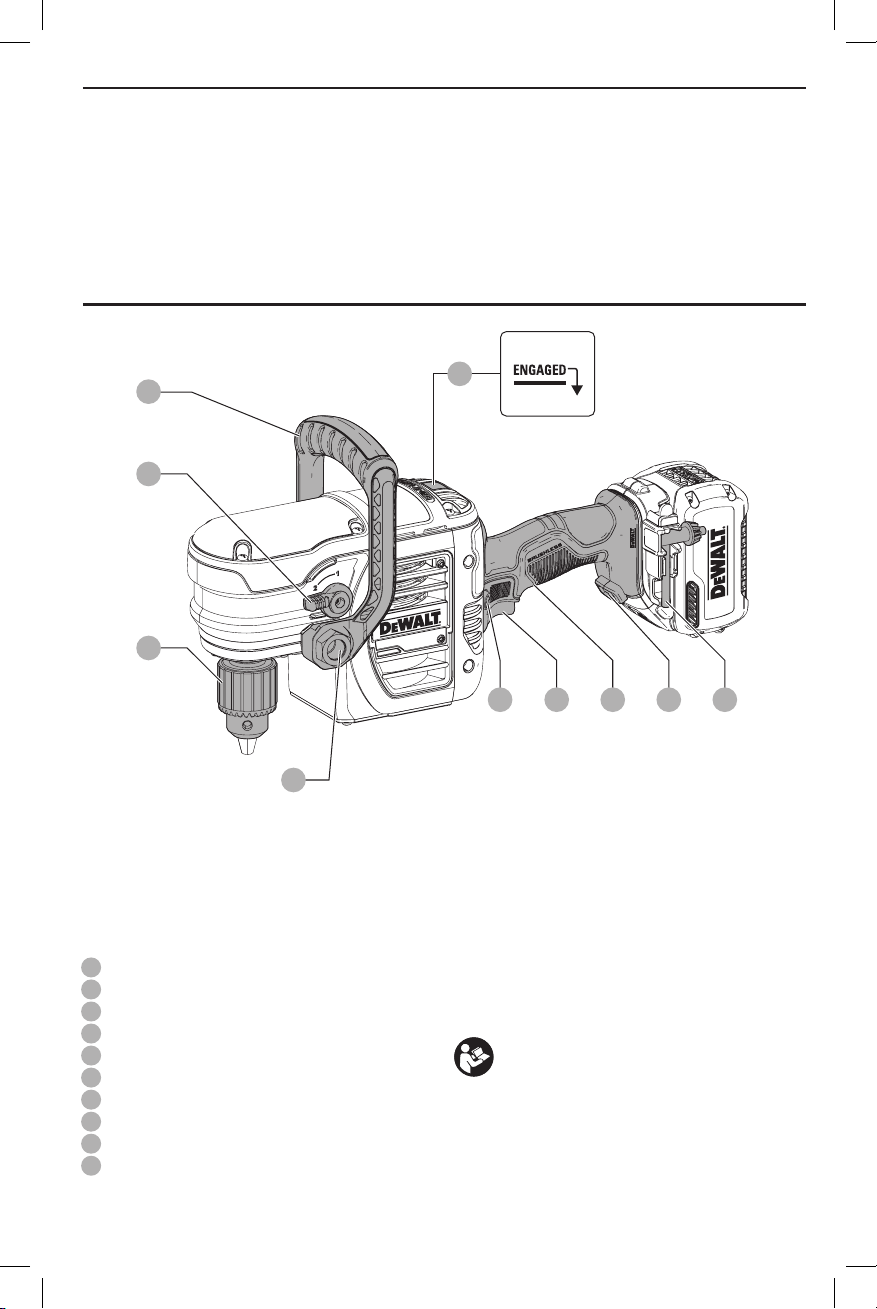
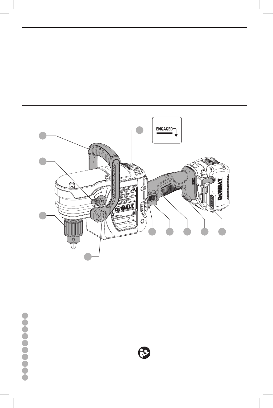
FIG. A
ENGLISH
1
2
6
5
7
10
94
83
1
Bail handle
2
Speed selector lever
3
Forward/reverse button
4
Trigger switch
5
Bail handle bolt
6
1/2" (13 mm) keyed chuck
7
E-Clutch® indicator
8
Main handle
9
Worklight
10
Chuck key
WARNING! Read all safety warnings and all
instructions. Failure to follow the warnings and
instructions may result in electric shock, fire and/or
seriousinjury.
WARNING: To reduce the risk of injury, read the
instructionmanual.
If you have any questions or comments about this or
any
1-800-4-
tool, call us toll free at:
(1-800-433-9258).
1
Page 4

ENGLISH
GENERAL POWER TOOL SAFETY WARNINGS
WARNING! Read all safety warnings and all
instructions. Failure to follow the warnings and
instructions may result in electric shock, fire and/or
seriousinjury.
SAVE ALL WARNINGS AND
INSTRUCTIONS FOR FUTURE
REFERENCE
The term “power tool” in the warnings refers to your mainsoperated (corded) power tool or battery-operated (cordless)
powertool.
1) Work Area Safety
a ) Keep work area clean and well lit. Cluttered or dark
areas inviteaccidents.
b ) Do not operate power tools in explosive
atmospheres, such as in the presence of
flammable liquids, gases or dust. Power tools
create sparks which may ignite the dust orfumes.
c ) Keep children and bystanders away while
operating a power tool. Distractions can cause you
to losecontrol.
2) Electrical Safety
a ) Power tool plugs must match the outlet. Never
modify the plug in any way. Do not use any
adapter plugs with earthed (grounded) power
tools. Unmodified plugs and matching outlets will
reduce risk of electricshock.
b ) Avoid body contact with earthed or grounded
surfaces such as pipes, radiators, ranges and
refrigerators. There is an increased risk of electric
shock if your body is earthed orgrounded.
c ) Do not expose power tools to rain or wet
conditions. Water entering a power tool will increase
the risk of electricshock.
d ) Do not abuse the cord. Never use the cord for
carrying, pulling or unplugging the power tool.
Keep cord away from heat, oil, sharp edges or
moving parts. Damaged or entangled cords increase
the risk of electricshock.
e ) When operating a power tool outdoors, use an
extension cord suitable for outdoor use. Use of
a cord suitable for outdoor use reduces the risk of
electricshock.
f ) If operating a power tool in a damp location
is unavoidable, use a ground fault circuit
interrupter (GFCI) protected supply. Use of a GFCI
reduces the risk of electricshock.
3) Personal Safety
a ) Stay alert, watch what you are doing and use
common sense when operating a power tool. Do
not use a power tool while you are tired or under
the influence of drugs, alcohol or medication. A
moment of inattention while operating power tools
may result in serious personalinjury.
b ) Use personal protective equipment. Always wear
eye protection. Protective equipment such as dust
mask, non-skid safety shoes, hard hat, or hearing
protection used for appropriate conditions will reduce
personalinjuries.
c ) Prevent unintentional starting. Ensure the
switch is in the off position before connecting to
power source and/or battery pack, picking up or
carrying the tool. Carrying power tools with your
finger on the switch or energizing power tools that
have the switch on invitesaccidents.
d ) Remove any adjusting key or wrench before
turning the power tool on. A wrench or a key left
attached to a rotating part of the power tool may
result in personalinjury.
e ) Do not overreach. Keep proper footing and
balance at all times. This enables better control of
the power tool in unexpectedsituations.
f ) Dress properly. Do not wear loose clothing or
jewelry. Keep your hair, clothing and gloves
away from moving parts. Loose clothes, jewelry or
long hair can be caught in movingparts.
g ) If devices are provided for the connection of dust
extraction and collection facilities, ensure these
are connected and properly used. Use of dust
collection can reduce dust-relatedhazards.
4) Power Tool Use and Care
a ) Do not force the power tool. Use the correct
power tool for your application. The correct power
tool will do the job better and safer at the rate for
which it wasdesigned.
b ) Do not use the power tool if the switch does not
turn it on and off. Any power tool that cannot be
controlled with the switch is dangerous and must
berepaired.
c ) Disconnect the plug from the power source and/
or the battery pack from the power tool before
making any adjustments, changing accessories,
or storing power tools. Such preventive safety
measures reduce the risk of starting the power
toolaccidentally.
d ) Store idle power tools out of the reach of children
and do not allow persons unfamiliar with the
power tool or these instructions to operate the
power tool. Power tools are dangerous in the hands
of untrainedusers.
e ) Maintain power tools. Check for misalignment or
binding of moving parts, breakage of parts and
any other condition that may affect the power
tool’s operation. If damaged, have the power
tool repaired before use. Many accidents are
caused by poorly maintained powertools.
f ) Keep cutting tools sharp and clean. Properly
maintained cutting tools with sharp cutting edges are
less likely to bind and are easier tocontrol.
g ) Use the power tool, accessories and tool bits, etc.
in accordance with these instructions, taking
into account the working conditions and the
work to be performed. Use of the power tool for
operations different from those intended could result
in a hazardoussituation.
2
Page 5

5) Battery Tool Use and Care
a ) Recharge only with the charger specified by the
manufacturer. A charger that is suitable for one type
of battery pack may create a risk of fire when used
with another batterypack.
b ) Use power tools only with specifically designated
battery packs. Use of any other battery packs may
create a risk of injury andfire.
c ) When battery pack is not in use, keep it away
from other metal objects, like paper clips, coins,
keys, nails, screws, or other small metal objects,
that can make a connection from one terminal to
another. Shorting the battery terminals together may
cause burns or afire.
d ) Under abusive conditions, liquid may be ejected
from the battery; avoid contact. If contact
accidentally occurs, flush with water. If liquid
contacts eyes, additionally seek medical help. Liquid
ejected from the battery may cause irritation orburns.
6) Service
a ) Have your power tool serviced by a qualified
repair person using only identical replacement
parts. This will ensure that the safety of the power
tool ismaintained.
Additional Safety Rules for Drills
• Use auxiliary handle(s), if supplied with the tool. Loss
of control can cause personal injury.
• Hold power tool by insulated gripping surfaces,
when performing an operation where the cutting
accessory may contact hidden wiring. Cutting
accessory contacting a “live” wire may make exposed
metal parts of the power tool “live” and could give the
operator an electric shock.
• Use clamps or other practical way to secure and
support the workpiece to a stable platform. Holding
the work by hand or against your body is unstable and
may lead to loss of control.
• Wear safety goggles or other eye protection.
Hammering and drilling operations cause chips to fly.
Flying particles can cause permanent eye damage.
• Keep handles dry, clean, and free from oil and
grease. This will enable better control of the tool.
Additional Safety Information
WARNING: ALWAYS use safety glasses. Everyday
eyeglasses are NOT safety glasses. Also use face or
dust mask if cutting operation is dusty. ALWAYS WEAR
CERTIFIED SAFETYEQUIPMENT:
• ANSI Z87.1 eye protection (CAN/CSA Z94.3),
• ANSI S12.6 (S3.19) hearing protection,
• NIOSH/OSHA/MSHA respiratoryprotection.
WARNING: Some dust created by power sanding,
sawing, grinding, drilling, and other construction
activities contains chemicals known to the State
of California to cause cancer, birth defects or
other reproductive harm. Some examples of these
chemicalsare:
• lead from lead-based paints,
ENGLISH
• crystalline silica from bricks and cement and other
masonry products, and
• arsenic and chromium from chemicallytreatedlumber.
Your risk from these exposures varies, depending on how
often you do this type of work. To reduce your exposure to
these chemicals: work in a well ventilated area, and work with
approved safety equipment, such as those dust masks that are
specially designed to filter out microscopicparticles.
• Avoid prolonged contact with dust from power
sanding, sawing, grinding, drilling, and other
construction activities. Wear protective clothing and
wash exposed areas with soap and water. Allowing
dust to get into your mouth, eyes, or lay on the skin may
promote absorption of harmfulchemicals.
WARNING: Use of this tool can generate and/
or disperse dust, which may cause serious and
permanent respiratory or other injury. Always use
NIOSH/OSHA approved respiratory protection
appropriate for the dust exposure. Direct particles
away from face andbody.
WARNING: Always wear proper personal hearing
protection that conforms to ANSI S12.6 (S3.19)
during use. Under some conditions and duration
of use, noise from this product may contribute to
hearingloss.
CAUTION: When not in use, place tool on its side
on a stable surface where it will not cause a
tripping or falling hazard. Some tools with large
battery packs will stand upright on the battery pack
but may be easily knockedover.
• Air vents often cover moving parts and should be
avoided. Loose clothes, jewelry or long hair can be
caught in movingparts.
The label on your tool may include the following symbols. The
symbols and their definitions are asfollows:
V ......................... volts
Hz ....................... hertz
min ..................... minutes
or DC ......direct current
...................... Class I Construction
(grounded)
…/min .............. per minute
BPM .................... beats per minute
IPM ..................... impacts per minute
RPM .................... revolutions per
minute
sfpm ................... surface feet per
minute
SPM .................... strokes per minute
A ......................... amperes
W ........................ watts
or AC ........... alternating current
or AC/DC .... alternating or
direct current
...................... Class II
Construction
(double insulated)
no ....................... no load speed
n ......................... rated speed
...................... earthing terminal
...................... safety alert symbol
..................... visible radiation
..................... respiratory
protection
..................... eye protection
..................... hearing protection
BATTERIES AND CHARGERS
The battery pack is not fully charged out of the carton.
Before using the battery pack and charger, read the
safety instructions below and then follow charging
3
Page 6
ENGLISH
DeWALT
DeWALT
DeWALT
DeWALT
proceduresoutlined.When ordering replacement battery
packs, be sure to include the catalog number andvoltage.
Your tool uses a
instructions before using your charger. Consult the chart
at the end of this manual for compatibility of chargers and
batterypacks.
charger. Be sure to read all safety
Important Safety Instructions for All
Battery Packs
WARNING: Read all safety warnings and all
instructions for the battery pack, charger and
power tool. Failure to follow the warnings and
instructions may result in electric shock, fire and/
or serious injury.
• Do not charge or use the battery pack in explosive
atmospheres, such as in the presence of flammable
liquids, gases or dust. Inserting or removing the battery
pack from the charger may ignite the dust orfumes.
• NEVER force the battery pack into the charger. DO
NOT modify the battery pack in any way to fit into
a non-compatible charger as battery pack may
rupture causing serious personal injury. Consult
the chart at the end of this manual for compatibility of
batteries andchargers.
• Charge the battery packs only in designated
• DO NOT splash or immerse in water or otherliquids.
• Do not store or use the tool and battery pack in
Transportation
chargers.
locations where the temperature may reach or
exceed 104°F (40°C) (such as outside sheds or metal
buildings in summer). For best life store battery packs in
a cool, drylocation.
NOTE: Do not store the battery packs in a tool with
the trigger switch locked on. Never tape the trigger
switch in the ONposition.
WARNING: Fire hazard. Never attempt to open the
battery pack for any reason. If the battery pack case
is cracked or damaged, do not insert into the charger.
Do not crush, drop or damage the battery pack. Do
not use a battery pack or charger that has received a
sharp blow, been dropped, run over or damaged in
any way (e.g., pierced with a nail, hit with a hammer,
stepped on). Damaged battery packs should be
returned to the service center forrecycling.
WARNING: Fire hazard. Do not store or carry the
battery pack so that metal objects can contact
exposed battery terminals. For example, do
not place the battery pack in aprons, pockets, tool
boxes, product kit boxes, drawers, etc., with loose
nails, screws, keys, etc. Transporting batteries
can possibly cause fires if the battery terminals
inadvertently come in contact with conductive
materials such as keys, coins, hand tools and the
like. The US Department of Transportation Hazardous
Material Regulations (HMR) actually prohibit
transporting batteries in commerce or on airplanes in
carry-on baggage UNLESS they are properly protected
from short circuits. So when transporting individual
battery packs, make sure that the battery terminals
are protected and well insulated from materials that
could contact them and cause a short circuit.
Shipping the
The DeWALT FLEXVOLT™ battery has two modes: Use and
Shipping.
Use Mode: When the FLEXVOLT™ battery stands alone or is
in a DeWALT 20V Max* product, it will operate as a 20V Max*
battery. When the FLEXVOLT™ battery is in a 60V Max* or a
120V Max* (two 60V Max* batteries) product, it will operate
as a 60V Max* battery.
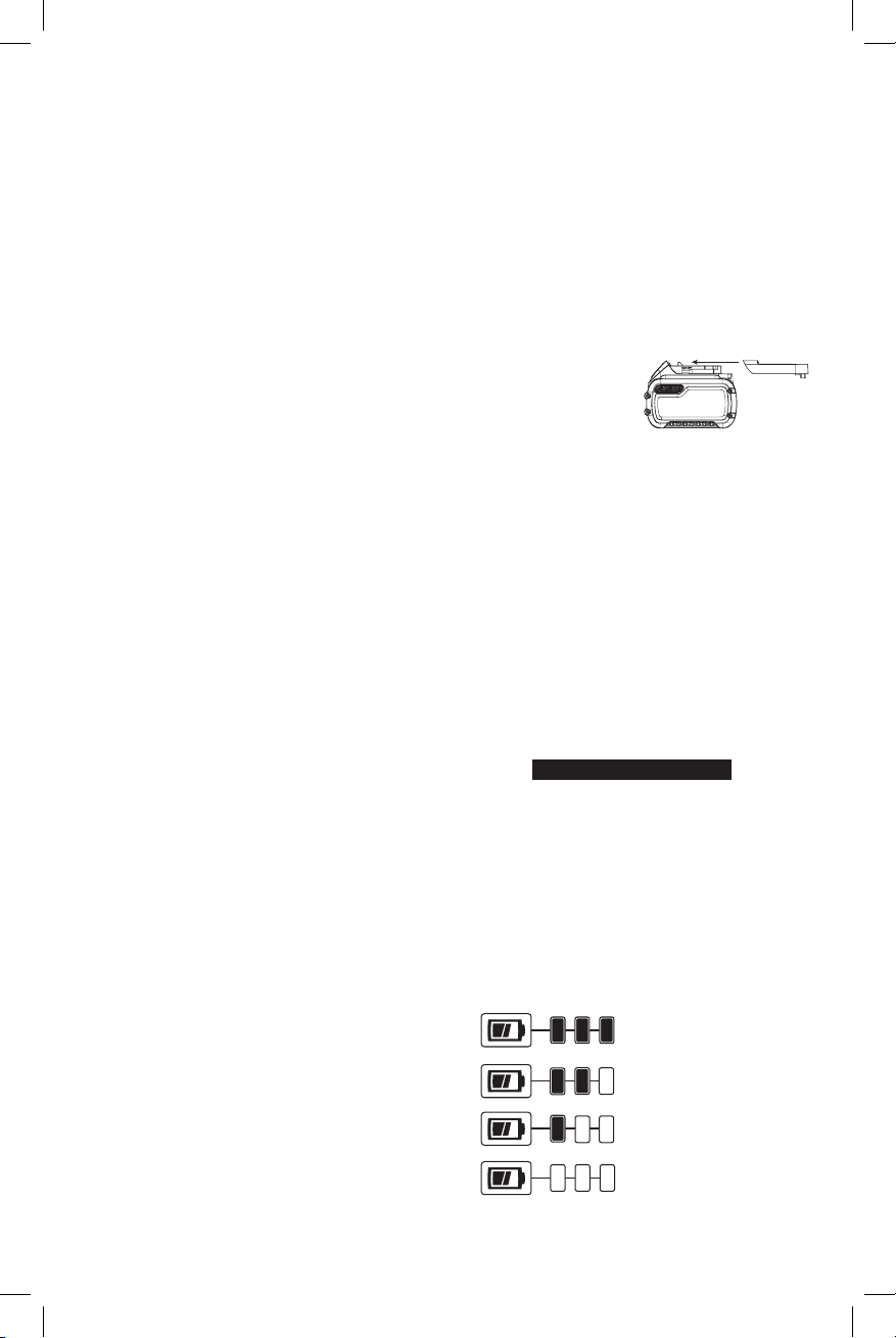
Shipping Mode: When
the cap is attached to
the FLEXVOLT™ battery,
the battery is in Shipping
Mode. Strings of cells are
electrically disconnected within the pack resulting in three
batteries with a lower Watt hour (Wh) rating as compared
to one battery with a higher Watt hour rating. This increased
quantity of three batteries with the lower Watt hour rating
can exempt the pack from certain shipping regulations that
are imposed upon the higher Watt hour batteries.
The battery label indicates two Watt Hour Ratings (see
example). Depending on how the battery is shipped, the
appropriate Whr rating must be used to determine the
applicable shipping requirements. If utilizing the shipping
cap, the pack will be considered 3 batteries at the Whr
indicated for “Shipping”. If shipping without the cap or in
a tool, the pack will be considered one battery at the Watt
hour rating indicated next to “Use”.
Transport Wh rating indicates 3 x 40 Wh, meaning 3
batteries of 40 Watt hours each. The Use Wh rating indicates
120 Watt hour (1 battery implied).
Example of Use and Shipping Label Marking
FLEXVOLT™ Battery
USE: 120 Wh Shipping: 3 x 40 Wh
Fuel Gauge Battery Packs (Fig. B)
Some
consists of three green LED lights that indicate the level of
charge remaining in the batterypack.
The fuel gauge is an indication of approximate levels of
charge remaining in the battery pack according to the
followingindicators:
battery packs include a fuel gauge which
75–100% charged
51–74% charged
< 50% charged
Pack needs to be charged
4
Page 7

To actuate the fuel gauge, press and hold the fuel gauge
DeWALT
DeWALT
DeWALT
DeWALT
DeWALT
11
button
illuminate designating the level of charge left. When the
level of charge in the battery is below the usable limit, the
fuel gauge will not illuminate and the battery will need to
berecharged.
NOTE: The fuel gauge is only an indication of the charge left
on the battery pack. It does not indicate tool functionality
and is subject to variation based on product components,
temperature and end-userapplication.
For more information regarding fuel gauge battery packs,
please contact call 1-800-4visit our website www.dewalt.com.
. A combination of the three green LED lights will
Fig. B
11
(1-800-433-9258) or
The RBRC® Seal
The RBRC® (Rechargeable Battery
Recycling Corporation) Seal on the nickel
cadmium, nickel metal hydride or lithiumion batteries (or battery packs) indicates
that the costs to recycle these batteries
(or battery packs) at the end of their useful life have already
been paid by
spent nickel cadmium, nickel metal hydride or lithium-ion
batteries in the trash or municipal solid waste stream and
the Call2Recycle® program provides an environmentally
consciousalternative.
Call 2 Recycle, Inc., in cooperation with
battery users, has established the program in the United
States and Canada to facilitate the collection of spent nickel
cadmium, nickel metal hydride or lithium-ion batteries. Help
protect our environment and conserve natural resources by
returning the spent nickel cadmium, nickel metal hydride
or lithium-ion batteries to an authorized
center or to your local retailer for recycling. You may also
contact your local recycling center for information on
where to drop off the spent battery. RBRC® is a registered
trademark of Call 2 Recycle,Inc.
. In some areas, it is illegal to place
and other
service
Important Safety Instructions for All
Battery Chargers
WARNING: Read all safety warnings and all
instructions for the battery pack, charger and
power tool. Failure to follow the warnings and
instructions may result in electric shock, fire and/
or serious injury.
• DO NOT attempt to charge the battery pack with
any chargers other than the ones in this manual.
The charger and battery pack are specifically designed to
worktogether.
• These chargers are not intended for any uses other
than charging
rechargeable batteries.
ENGLISH
Any other uses may result in risk of fire, electric shock
orelectrocution.
• Do not expose the charger to rain orsnow.
• Pull by the plug rather than the cord when
disconnecting the charger. This will reduce the risk of
damage to the electric plug andcord.
• Make sure that the cord is located so that it will not
be stepped on, tripped over or otherwise subjected
to damage orstress.
• Do not use an extension cord unless it is absolutely
necessary. Use of improper extension cord could result in
risk of fire, electric shock orelectrocution.
• When operating a charger outdoors, always provide
a dry location and use an extension cord suitable
for outdoor use. Use of a cord suitable for outdoor use
reduces the risk of electricshock.
• An extension cord must have adequate wire size
(AWG or American Wire Gauge) for safety. The smaller
the gauge number of the wire, the greater the capacity
of the cable, that is, 16 gauge has more capacity than 18
gauge. An undersized cord will cause a drop in line voltage
resulting in loss of power and overheating. When using
more than one extension to make up the total length,
be sure each individual extension contains at least the
minimum wire size. The following table shows the correct
size to use depending on cord length and nameplate
ampere rating. If in doubt, use the next heavier gauge. The
lower the gauge number, the heavier thecord.
Minimum Gauge for Cord Sets
Volts
120 V 25 (7.6) 50 (15.2) 100 (30.5) 150 (45.7)
240 V 50 (15.2) 100 (30.5) 200 (61.0) 300 (91.4)
Ampere Rating
More
Not
Than
More
Than
0 6 18 16 16 14
6 10 18 16 14 12
10 12 16 16 14 12
12 16 14 12 Not Recommended
• Do not place any object on top of the charger or
place the charger on a soft surface that might block
the ventilation slots and result in excessive internal
heat. Place the charger in a position away from any heat
source. The charger is ventilated through slots in the top
and the bottom of thehousing.
• Do not operate the charger with a damaged cord
orplug.
• Do not operate the charger if it has received a sharp
blow, been dropped or otherwise damaged in any
way. Take it to an authorized servicecenter.
• Do not disassemble the charger; take it to an
authorized service center when service or repair
is required. Incorrect reassembly may result in a risk of
electric shock, electrocution orfire.
• Disconnect the charger from the outlet before
attempting any cleaning. This will reduce the risk of
Total Length of Cord in Feet
(meters)
American Wire Gauge
5
Page 8
ENGLISH
DeWALT
electric shock. Removing the battery pack will not reduce
thisrisk.
• NEVER attempt to connect 2 chargerstogether.
• The charger is designed to operate on standard
120V household electrical power. Do not attempt to
use it on any other voltage. This does not apply to the
vehicularcharger.
WARNING: Shock hazard. Do not allow any liquid to
get inside the charger. Electric shock mayresult.
WARNING: Burn hazard. Do not submerge the
battery pack in any liquid or allow any liquid to
enter the battery pack. Never attempt to open the
battery pack for any reason. If the plastic housing of
the battery pack breaks or cracks, return to a service
center for recycling.
CAUTION: Burn hazard. To reduce the risk of injury,
charge only
Other types of batteries may overheat and burst
resulting in personal injury and propertydamage.
NOTICE: Under certain conditions, with the charger
plugged into the power supply, the charger can
be shorted by foreign material. Foreign materials
of a conductive nature, such as, but not limited to,
grinding dust, metal chips, steel wool, aluminum
foil or any buildup of metallic particles should be
kept away from the charger cavities. Always unplug
the charger from the power supply when there is no
battery pack in the cavity. Unplug the charger before
attempting toclean.
rechargeable battery packs.
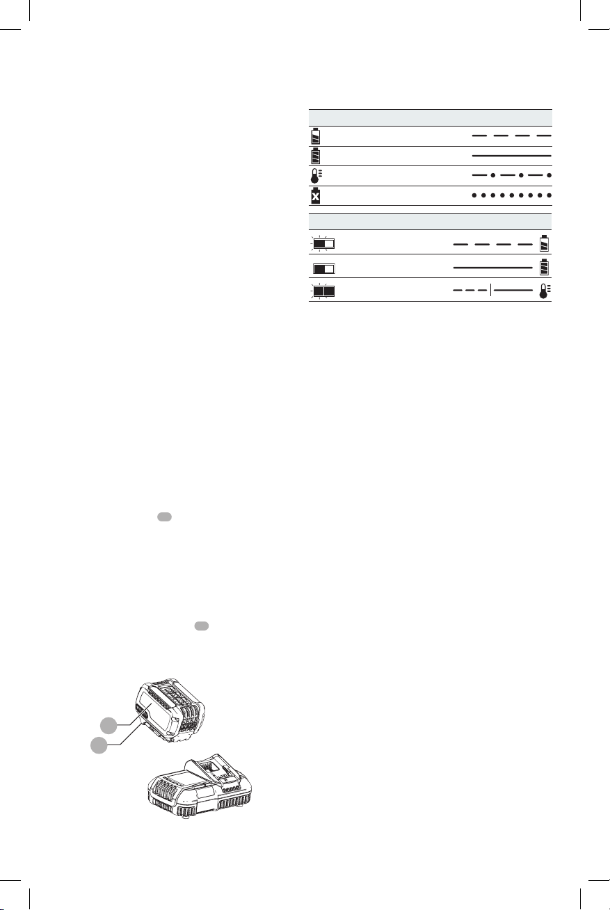
Charging a Battery (Fig. C)
1. Plug the charger into an appropriate outlet before
inserting battery pack.
2. Insert the battery pack
the battery pack is fully seated in the charger. The red
(charging) light will blink continuously indicating that
the charging process has started.
3. The completion of charge will be indicated by the red
light remaining ON continuously. The battery pack is
fully charged and may be used at this time or left in the
charger. To remove the battery pack from the charger,
push the battery release button
NOTE: To ensure maximum performance and life of lithiumion battery packs, charge the battery pack fully before
firstuse.
Fig. C
12
13
12
into the charger, making sure
13
on the battery pack.
Charger Operation
Refer to the indicators below for the charge status of the
battery pack.
DCB101
Charging
Fully Charged
Hot/Cold Pack Delay
Problem Pack or Charger
DCB107, DCB112, DCB113, DCB115, DCB118
Charging
Fully Charged
Hot/Cold Pack Delay*
* DCB107, DCB112, DCB113, DCB115, DCB118: The red
light will continue to blink, but a yellow indicator light will
be illuminated during this operation. Once the battery
pack has reached an appropriate temperature, the yellow
light will turn off and the charger will resume the charging
procedure.
The compatible charger(s) will not charge a faulty battery
pack. The charger will indicate faulty battery pack by
refusing to light or by displaying a problem pack or charger
blink pattern.
NOTE: This could also mean a problem with a charger.
If the charger indicates a problem, take the charger and
battery pack to be tested at an authorized service center.
Hot/Cold Pack Delay
When the charger detects a battery pack that is too hot
or too cold, it automatically starts a Hot/Cold Pack Delay,
suspending charging until the battery pack has reached an
appropriate temperature. The charger then automatically
switches to the pack charging mode. This feature ensures
maximum battery pack life.
A cold battery pack will charge at a slower rate than a warm
battery pack. The battery pack will charge at that slower rate
throughout the entire charging cycle and will not return to
maximum charge rate even if the battery pack warms.
The DCB118 charger is equipped with an internal fan
designed to cool the battery pack. The fan will turn on
automatically when the battery pack needs to be cooled.
Never operate the charger if the fan does not operate
properly or if ventilation slots are blocked. Do not permit
foreign objects to enter the interior of the charger.
Lithium-Ion Battery Packs Only
Li-Ion tools are designed with an Electronic Protection
System that will protect the battery pack against
overloading, overheating or deep discharge.
The tool will automatically turn off if the Electronic
Protection System engages. If this occurs, place the lithiumion battery pack on the charger until it is fully charged.
6
Page 9

Wall Mounting
DCB107, DCB112, DCB113, DCB115, DCB118
These chargers are designed to be wall mountable or to
sit upright on a table or work surface. If wall mounting,
locate the charger within reach of an electrical outlet,
and away from a corner or other obstructions which may
impede air flow. Use the back of the charger as a template
for the location of the mounting screws on the wall. Mount
the charger securely using drywall screws (purchased
separately) at least 1" (25.4 mm) long, with a screw head
diameter of 0.28–0.35" (7–9mm), screwed into wood to an
optimal depth leaving approximately 7/32" (5.5 mm) of the
screw exposed. Align the slots on the back of the charger
with the exposed screws and fully engage them in the slots.
Charger Cleaning Instructions
WARNING: Shock hazard. Disconnect the charger
from the AC outlet before cleaning. Dirt and grease
may be removed from the exterior of the charger using
a cloth or soft non-metallic brush. Do not use water or
any cleaning solutions.
Important Charging Notes
1. Longest life and best performance can be obtained if
the battery pack is charged when the air temperature is
between 65°F and 75°F (18° – 24°C). DO NOT charge
the battery pack in an air temperature below +40°F
(+4.5°C), or above +104°F (+40°C). This is important
and will prevent serious damage to the battery pack.
2. The charger and battery pack may become warm to the
touch while charging. This is a normal condition, and
does not indicate a problem. To facilitate the cooling of
the battery pack after use, avoid placing the charger or
battery pack in a warm environment such as in a metal
shed or an uninsulated trailer.
3. If the battery pack does not charge properly:
a. Check operation of receptacle by plugging in a lamp
or other appliance;
b. Check to see if receptacle is connected to a light
switch which turns power off when you turn out the
lights;
c. Move the charger and battery pack to a location
where the surrounding air temperature is
approximately 65°F – 75°F (18° – 24°C);
d. If charging problems persist, take the tool, battery
pack and charger to your local service center.
4. The battery pack should be recharged when it fails to
produce sufficient power on jobs which were easily
done previously. DO NOT CONTINUE to use under these
conditions. Follow the charging procedure. You may
also charge a partially used pack whenever you desire
with no adverse effect on the battery pack.
5. Foreign materials of a conductive nature such as, but
not limited to, grinding dust, metal chips, steel wool,
aluminum foil, or any buildup of metallic particles
should be kept away from charger cavities. Always
unplug the charger from the power supply when there
ENGLISH
is no battery pack in the cavity. Unplug the charger
before attempting to clean.
6. Do not freeze or immerse the charger in water or any
other liquid.
Storage Recommendations
1. The best storage place is one that is cool and dry, away
from direct sunlight and excess heat or cold.
2. For long storage, it is recommended to store a fully
charged battery pack in a cool dry place out of the
charger for optimal results.
NOTE: Battery packs should not be stored completely
depleted of charge. The battery pack will need to be
recharged before use.
SAVE THESE INSTRUCTIONS FOR
FUTURE USE
COMPONENTS (FIG. A)
WARNING: Never modify the power tool or any part
of it. Damage or personal injury couldresult.
Refer to Figure A at the beginning of this manual for a
complete list ofcomponents.
INTENDED USE
The DCD460 heavy-duty stud and joist drill is designed for
professional drilling at various work sites (i.e., construction
sites). DO NOT use under wet conditions or in presence of
flammable liquids or gases.
These heavy-duty stud and joist drills are professional power
tools. DO NOT let children come into contact with the tool.
Supervision is required when inexperienced operators use
this tool.
ASSEMBLY AND ADJUSTMENTS
WARNING: To reduce the risk of serious personal
injury, turn unit off and remove the battery pack
before making any adjustments or removing/
installing attachments or accessories. An
accidental start-up can causeinjury.
Torque
WARNING: This is a high-torque drill. To reduce the
risk of serious personal injury, ALWAYS hold tool
firmly with both hands in the proper position for
operation as shown.
Torque is the twisting action the drill produces in regards
to the rotating bit. As the drill bit meets resistance in the
material being drilled, the motor responds by adjusting the
output torque to meet the requirement up to the maximum
capacity of the motor and gear system.
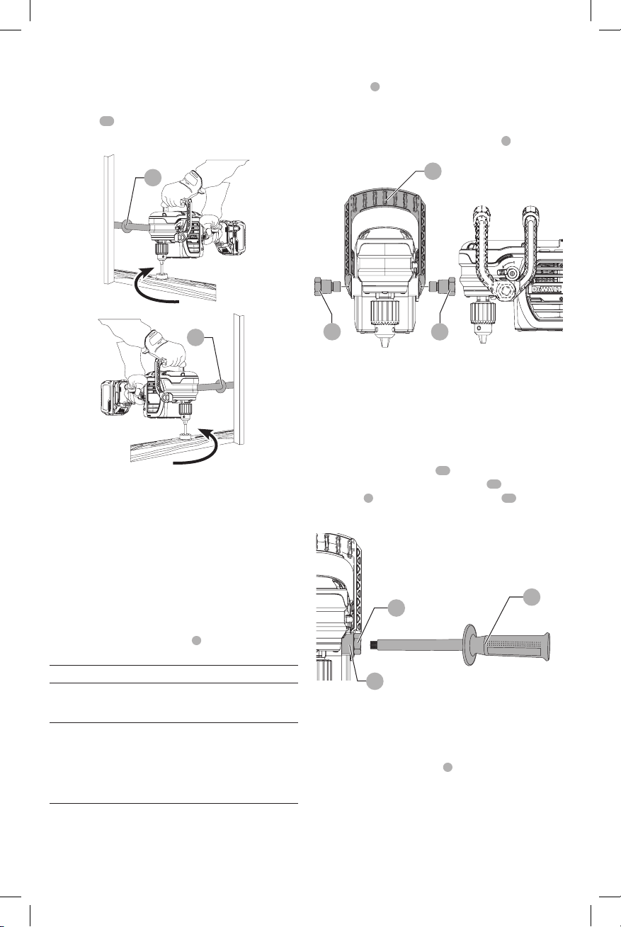
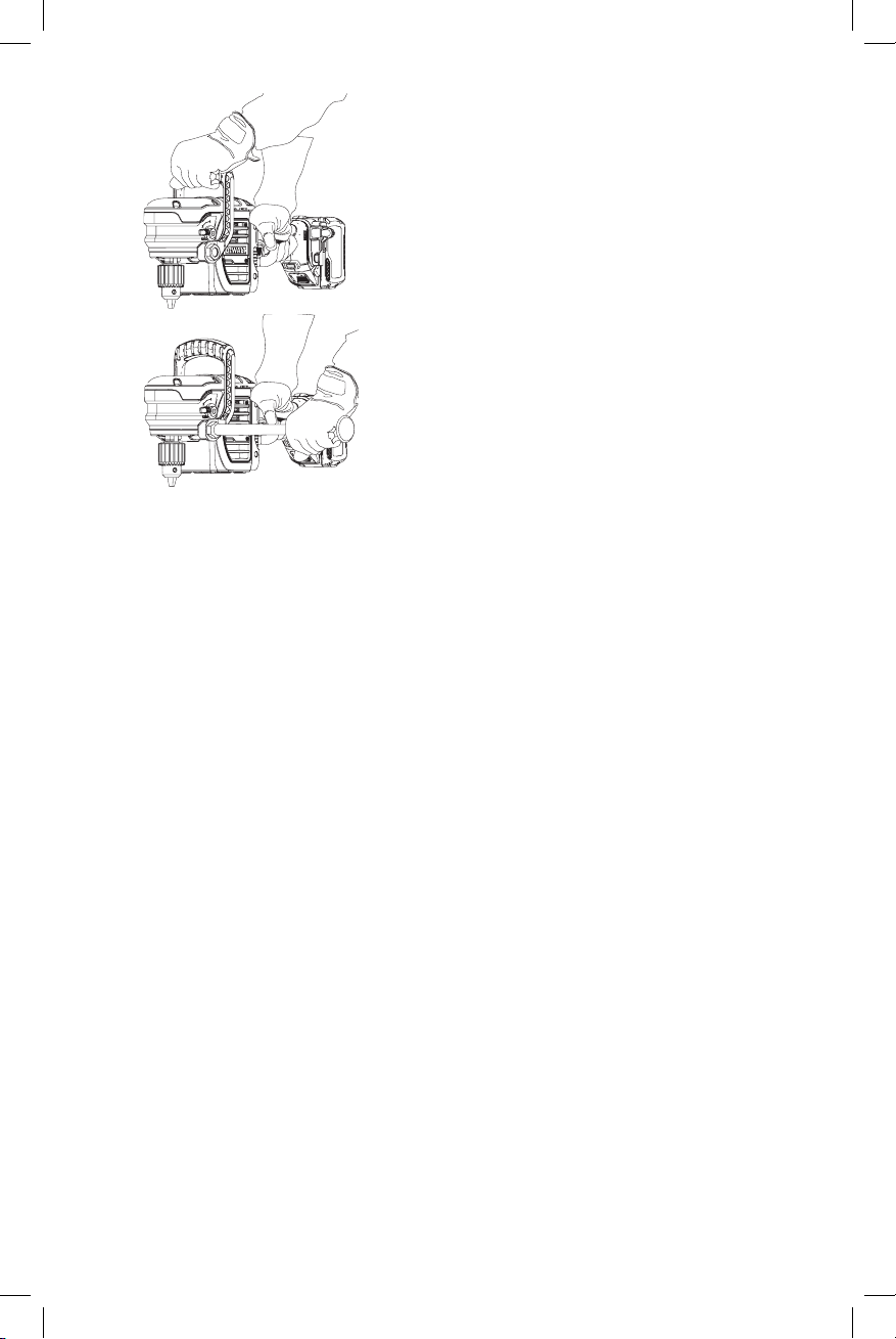
Bracing the Tool (Fig. D, J)
WARNING: To reduce the risk of serious personal
injury, ALWAYS hold or brace the tool securely in
anticipation of a sudden reaction.
With hands in the proper hand position (also refer to Fig. J),
brace the tool as shown in FigureD.
7
Page 10
ENGLISH
DeWALT
The bit rotates clockwise when the tool is in the forward
position and counterclockwise when the tool is in the
reverse position. If the bit binds, the tool will slow to a
manageable level. Using proper hand position, brace the
side handle
support (Fig.D).
14
or tool body against a stud for better
Fig. D
14
FORWARD
Bail Handle (Fig. E)
A bail handle
use as an additional handle. Assemble the bail handle in
one of the positions shown in FigureE. When changing the
location of the bail handle from one position to the other,
completely remove the two bail handle bolts
Flip the handle over and reinstall.
Fig. E
1
is provided for carrying the tool and for
5
securing it.
1
14
REVERSE
Clutch
The DCD460 is equipped with a mechanical slip clutch. The
clutch is active when the low speed (1) is selected. When
the bit or cutter bites into the workpiece, the clutch will slip
and a ratcheting sound will be heard. Release the trigger.
Continued clutching of the tool will reduce the life of this
feature.
E-Clutch® System (Fig. 1)
The DCD460 is equipped with the
system. This feature senses the motion of the tool and
reduces the motor torque to a manageable level if
necessary. The E-Clutch® indicator
indicate status.
INDICATOR DIAGNOSIS SOLUTION
OFF Tool is
functioning
normally
SOLID E-Clutch®
System has
been activated
(ENGAGED)
Follow all warnings and
instructions when operating
the tool.
With the tool properly
supported, release trigger.
The tool will function
normally when the trigger
is depressed again and the
indicator light will go out
E-Clutch®
7
will illuminate to
5
5
Side Handle (Fig. F)
WARNING: To reduce the risk of personal injury,
always operate the tool with the side handle properly
installed and tightened. Failure to do so may result
in the side handle slipping during tool operation and
subsequent loss of control. Hold tool with both hands
to maximize control.
The two position side handle
either side of tool. Thread the side handle
handle bolt
side. Tighten securely by hand.
Fig. F
5
or directly into threaded holes
15
14
can be assembled into
14
into the bail
15
on desired
5
14
Speed Selector (Fig. A)
NOTICE: Risk of tool damage. Do not rotate the speed
selector lever while the drill is running or coasting,
damage may occur to the tool.
Rotate the speed selector lever
1 = low speed
2 = high speed
NOTE: The first time the tool is run after changing speeds,
you may hear a click on start up. This is normal and does not
indicate a problem.
2
to the desired speed:
8
Page 11

Variable Speed Trigger Switch (Fig. A)
Depressing the variable speed trigger switch
tool on, releasing the variable speed trigger switch turns
the tool off. The variable speed trigger switch permits speed
control—the farther the trigger is depressed, the higher the
speed of the drill.
4
turns the
Forward/Reverse Button (Fig. A)
A forward/reverse button
tool. It is located in front of the trigger switch.
To select forward rotation, release the trigger switch
depress the forward/reverse button on the right side of the
tool.
To select reverse, depress the forward/reverse button on
the left side of the tool. When changing the position of the
button, be sure the trigger is released.
NOTE: The first time the tool is run after changing the
direction of rotation, you may hear a click on start up. This is
normal and does not indicate a problem.
3
determines the direction of the
4
and
Keyed Chuck
Open the chuck jaws by turning collar by hand and insert
the shank of the bit about 3/4" (19 mm) into chuck. Tighten
the chuck collar by hand. Place chuck key (
each of the three holes, and tighten in clockwise direction.
It’s important to tighten chuck with all three holes. To
release the bit, turn the chuck counterclockwise in just one
hole, then loosen the chuck by hand.
NOTE: When using hex shank or three-sided shank bits, be
sure to align the flat sides of the bit with the chuck jaws to
ensure the bit is properly engaged by the jaws.
Removal of Keyed Chuck (Fig. G)
Remove the left-handed chuck screw using a T25 torx
wrench, rotating clockwise to loosen.Tighten the chuck
around the shorter end of a hex wrench (not supplied)
of 3/8" (10 mm) size. With the tool braced securely, use
a soft hammer and strike the hex wrench sharply in the
counterclockwise direction when viewed from the front
of the tool. This will loosen the chuck so that it can be
removed by hand.
Keyed Chuck Installation (Fig. H)
Screw the chuck on by hand as far as it will go. Insert the
shorter end of a hex wrench (not supplied) of 3/8" (10 mm)
size and strike it in the clockwise direction with a soft
hammer. Reinstall the left handed clutch screw.
FIG. G
10
, Fig.A) in
FIG. H
ENGLISH
Worklight (Fig. A)
CAUTION: Do not stare into worklight. Serious eye
injury could result.
The worklight
worklight is activated when the trigger switch is depressed,
and will automatically turn off 20 seconds after the trigger
switch is released. If the trigger switch remains depressed,
the worklight will remain on.
NOTE: The worklight is for lighting the immediate work
surface and is not intended to be used as a flashlight.
9
is located on the foot of the tool. The
OPERATION
WARNING: To reduce the risk of serious personal
injury, turn unit off and remove the battery pack
before making any adjustments or removing/
installing attachments or accessories. An
accidental start-up can causeinjury.
Installing and Removing the Battery Pack
(Fig. I)
NOTE: For best results, make sure your battery pack is
fullycharged.
To install the battery pack
battery pack with the rails inside the tool’s handle and slide
it into the handle until the battery pack is firmly seated in
the tool and ensure that it does notdisengage.
To remove the battery pack from the tool, press the release
13
button
handle. Insert it into the charger as described in the charger
section of thismanual.
Squeeze the tool trigger for three seconds to dissipate
the slight electric charge that may still be in the tool. The
worklight may come on for a brief moment.
and firmly pull the battery pack out of the tool
Fig. I
12
13
12
into the tool handle, align the
Proper Hand Position (Fig. J)
WARNING: To reduce the risk of serious personal injury,
ALWAYS use proper hand position as shown.
WARNING: To reduce the risk of serious personal injury,
ALWAYS hold securely in anticipation of a sudden
reaction.
Always hold tool firmly with both hands in the proper
position for operation as shown.
9
Page 12
ENGLISH
DeWALT
DeWALT
DeWALT
DeWALT
DeWALT
Fig. J
Drilling
WARNING: TO REDUCE THE RISK OF PERSONAL
INJURY, ALWAYS ensure workpiece is anchored or
clamped firmly. If drilling thin material, use a wood
“back-up” block to prevent damage to the material.
1. Use sharp drill bits only. For WOOD, use twist drill bits,
spade bits, power auger bits, or hole saws. For METAL,
use steel twist drill bits or hole saws.
2. Always apply pressure in a straight line with the bit. Use
enough pressure to keep drill biting, but do not push
hard enough to stall the motor or deflect the bit.
3. Hold tool firmly with both hands to control the twisting
action of the drill.
4. IF DRILL STALLS, it is usually because it is being
overloaded or improperly used. RELEASE TRIGGER
IMMEDIATELY, remove drill bit from work, and
determine cause of stalling. DO NOT CLICK TRIGGER ON
AND OFF IN AN ATTEMPT TO START A STALLED DRILL
— THIS CAN DAMAGE THE DRILL.
5. To minimize stalling or breaking through the material,
reduce pressure on drill and ease the bit through the
last fractional part of the hole.
6. Keep the motor running when pulling the bit back out
of a drilled hole. This will help prevent jamming.
Drilling in Metal
Start drilling with slow speed and increase to full power
while applying firm pressure on the tool. A smooth even
flow of metal chips indicates the proper drilling rate. Use a
cutting lubricant when drilling metals. The exceptions are
cast iron and brass which should be drilled dry.
NOTE: Large [5/16" (8 mm) to 1/2" (13 mm)] holes in steel
can be made easier if a pilot hole [5/32" (4 mm) to 3/16" (5
mm)] is drilled first.
Drilling in Wood
Start drilling with slow speed and increase to full power
while applying firm pressure on the tool. Holes in wood can
be made with the same twist drills used for metal. These
bits may overheat unless pulled out frequently to clear chips
from the flutes. Work that is apt to splinter should be backed
up with a block of wood.
MAINTENANCE
WARNING: To reduce the risk of serious personal
injury, turn unit off and remove the battery pack
before making any adjustments or removing/
installing attachments or accessories. An
accidental start-up can causeinjury.
Lubrication
Your tool was properly lubricated before leaving the factory.
In from two to six months, depending upon use, take or
send your tool to a
service organization for a complete cleaning, inspection and
relubrication.
Service Center or other qualified
Cleaning
WARNING: Blow dirt and dust out of all air vents with
clean, dry air at least once a week. To minimize the risk
of eye injury, always wear ANSI Z87.1 approved eye
protection when performingthis.
WARNING: Never use solvents or other harsh
chemicals for cleaning the non-metallic parts of
the tool. These chemicals may weaken the plastic
materials used in these parts. Use a cloth dampened
only with water and mild soap. Never let any liquid
get inside the tool; never immerse any part of the tool
into aliquid.
Accessories
WARNING: Since accessories, other than those
offered by
product, use of such accessories with this tool could be
hazardous. To reduce the risk of injury, only
recommended accessories should be used with
thisproduct.
Recommended accessories for use with your tool
are available at extra cost from your local dealer or
authorized service center. If you need assistance in
locating any accessory, please contact
Tool Co., 701East Joppa Road, Towson, MD 21286, call
1-800-4www.dewalt.com.
, have not been tested with this
(1-800-433-9258) or visit our website:
Industrial
10
Page 13
MAXIMUM RECOMMENDED
DeWALT
DeWALT
DeWALT
DeWALT
DeWALT
DeWALT
DeWALT
DeWALT
DeWALT
CAPACITIES
LOW SPEED HIGH SPEED
RPM 0–300 0–1250
WOOD, FLAT BORING
HOLE SAWS 6-1/4"
SHIP AUGER
SELF-FEED BITS 4-5/8"
CLUTCH OPERATIVE YES NO
E-Clutch® System (DCD460) YES YES
NOTE: For holes in metal larger than 1/2" (13mm) use
hole saws.
–
(152.4 mm)
–
(102 mm)
1-1/2"
(38 mm)
1-1/2"
(38 mm)
2-9/16"
(65 mm)
Repairs
The charger and battery pack are notserviceable.
WARNING: To assure product SAFETY and
RELIABILITY, repairs, maintenance and adjustment
(including brush inspection and replacement) should
be performed by a
or a
identical replacementparts.
authorized service center. Always use
factory service center
Register Online
Thank you for your purchase. Register your product nowfor:
• WARRANTY SERVICE: Registering your product will
help you obtain more efficient warranty service in case
there is a problem with yourproduct.
• CONFIRMATION OF OWNERSHIP: In case of
an insurance loss, such as fire, flood or theft, your
registration of ownership will serve as your proof
ofpurchase.
• FOR YOUR SAFETY: Registering your product will
allow us to contact you in the unlikely event a safety
notification is required under the Federal Consumer
SafetyAct.
Register online at www.dewalt.com/register.
Three Year Limited Warranty
will repair, without charge, any defects due to
faulty materials or workmanship for three years from the
date of purchase. This warranty does not cover part failure
due to normal wear or tool abuse. For further detail of
warranty coverage and warranty repair information, visit
www.dewalt.com or call 1-800-4This warranty does not apply to accessories or damage
caused where repairs have been made or attempted by
others. This warranty gives you specific legal rights and
you may have other rights which vary in certain states
orprovinces.
In addition to the warranty,
byour:
(1-800-433-9258).
tools are covered
ENGLISH
1 YEAR FREE SERVICE
will maintain the tool and replace worn parts
caused by normal use, for free, any time during the first year
afterpurchase.
2 YEARS FREE SERVICE ON DEWALT BATTERY PACKS
DC9071, DC9091, DC9096, DC9182, DC9280, DC9360,
DCB120, DCB127, DCB201, DCB203, DCB203BT, DCB207,
3 YEARS FREE SERVICE ON DEWALT BATTERY PACKS
DCB200, DCB204, DCB204BT, DCB205, DCB606
NOTE: Battery warranty voided if the battery pack is
tampered with in any way.
for any injury caused by tampering and may prosecute
warranty fraud to the fullest extent permitted bylaw.
90 DAY MONEY BACK GUARANTEE
If you are not completely satisfied with the performance of
your
can return it within 90 days from the date of purchase with
a receipt for a full refund – no questionsasked.
LATIN AMERICA: This warranty does not apply to products
sold in Latin America. For products sold in Latin America,
see country specific warranty information contained in
the packaging, call the local company or see website for
warrantyinformation.
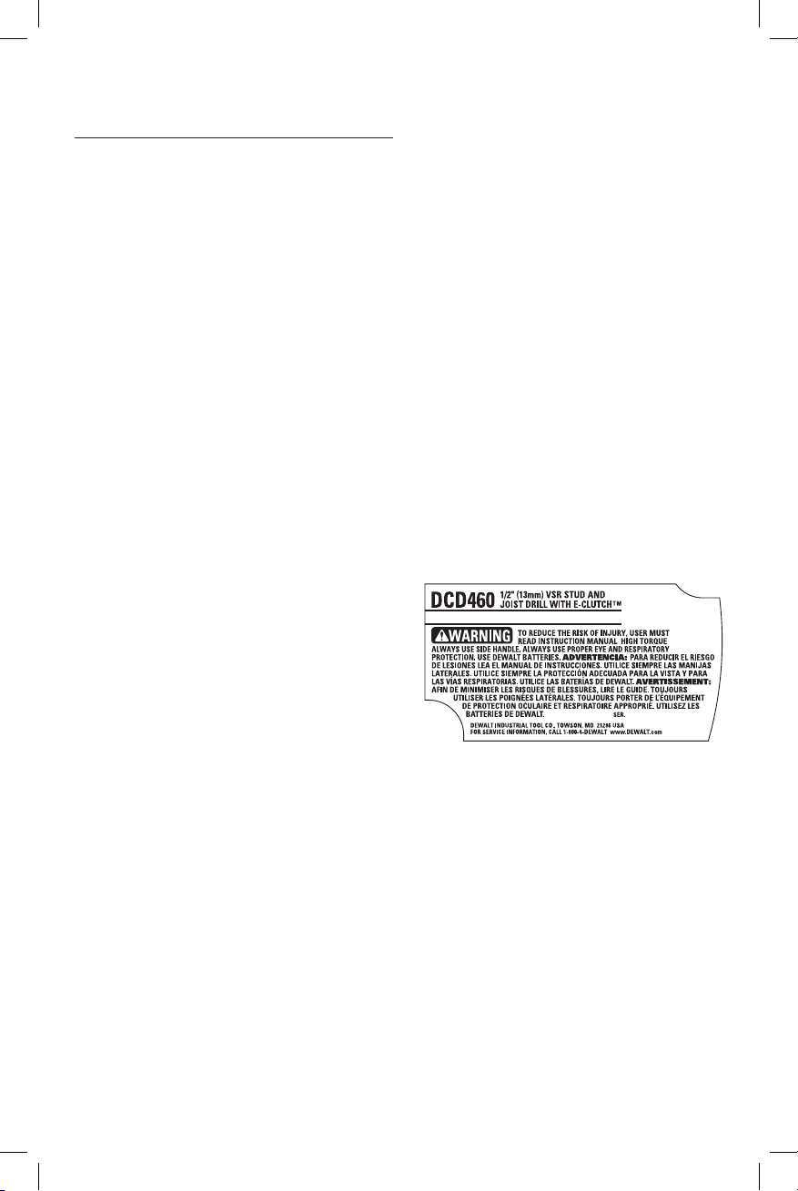
FREE WARNING LABEL REPLACEMENT: If your warning
labels become illegible or are missing, call 1-800-4(1-800-433-9258) for a freereplacement.
Power Tool, Laser, or Nailer for any reason, you
DCB361
is not responsible
11
Page 14
FRENCH
DeWALT
DeWALT
Définitions : lignes directrices en matière de sécurité
Les définitions ci-dessous décrivent le niveau de danger pour chaque
mot-indicateur employé. Lire le mode d’emploi et porter une attention particulière à cessymboles.
DANGER: indique une situation dangereuse imminente qui, si elle n’est pas évitée, entraînera la mort ou des
blessuresgraves.
AVERTISSEMENT: indique une situation potentiellement dangereuse qui, si elle n’est pas évitée, pourrait entraîner la
mort ou des blessuresgraves.
ATTENTION: indique une situation potentiellement dangereuse qui, si elle n’est pas évitée, pourrait entraîner des
blessures légères oumodérées.
AVIS : indique une pratique ne posant aucun risque de dommages corporels mais qui par contre, si rien n’est fait
pour l’éviter, pourrait poser des risques de dommages matériels.
FIG. A
1
2
6
5
7
10
94
83
1
Poignée étrier
2
Sélecteur de vitesse
3
Bouton marche avant/arrière
4
Gâchette
5
Boulon de poignée étrier
6
Mandrin à clé de 13mm (1/2po.)
7
Voyant E-clutch®
8
Poignée principale
9
Lampe de travail
10
Clé de mandrin
12
AVERTISSEMENT! lire tous les avertissements de
sécurité et toutes les directives. Le non-respect
des avertissements et des directives pourrait se
solder par un choc électrique, un incendie et/ou une
blessuregrave.
AVERTISSEMENT : afin de réduire le risque de
blessures, lire le mode d’emploi del’outil.
Pour toute question ou remarque au sujet de cet outil
ou de tout autre outil
sans frais : 1-800-4-
, composez le numéro
(1-800-433-9258).
Page 15

CONSERVER TOUS LES
AVERTISSEMENTS ET TOUTES
LES DIRECTIVES POUR UN USAGE
ULTÉRIEUR
AVERTISSEMENTS DE SÉCURITÉ GÉNÉRAUX
POUR LES OUTILS ÉLECTRIQUES
Le terme « outil électrique » cité dans les avertissements se
rapporte à votre outil électrique à alimentation sur secteur
(avec fil) ou par piles (sans fil).
AVERTISSEMENT! lire tous les avertissements de
sécurité et toutes les directives. Le non-respect
des avertissements et des directives pourrait se
solder par un choc électrique, un incendie et/ou une
blessuregrave.
1) Sécurité du lieu de travail
a ) Tenir l’aire de travail propre et bien éclairée.
Les lieux encombrés ou sombres sont propices
auxaccidents.
b ) Ne pas faire fonctionner d’outils électriques
dans un milieu déflagrant, tel qu’en présence de
liquides, de gaz ou de poussières inflammables.
Les outils électriques produisent des étincelles qui
pourraient enflammer la poussière ou lesvapeurs.
c ) Éloigner les enfants et les personnes à proximité
pendant l’utilisation d’un outil électrique. Une
distraction pourrait en faire perdre la maîtrise à
l’utilisateur.
2) Sécurité en matière d’électricité
a ) Les fiches des outils électriques doivent
correspondre à la prise. Ne jamais modifier la
fiche d’aucune façon. Ne jamais utiliser de fiche
d’adaptation avec un outil électrique mis à la
terre. Le risque de choc électrique sera réduit par
l’utilisation de fiches non modifiées correspondant à
laprise.
b ) Éviter tout contact physique avec des surfaces
mises à la terre comme des tuyaux, des
radiateurs, des cuisinières et des réfrigérateurs.
Le risque de choc électrique est plus élevé si votre corps
est mis à laterre.
c ) Ne pas exposer les outils électriques à la pluie ou
à l’humidité. La pénétration de l’eau dans un outil
électrique augmente le risque de chocélectrique.
d ) Ne pas utiliser le cordon de façon abusive.
Ne jamais utiliser le cordon pour transporter,
tirer ou débrancher un outil électrique. Tenir le
cordon éloigné de la chaleur, de l’huile, des bords
tranchants et des pièces mobiles. Les cordons
endommagés ou enchevêtrés augmentent les risques
de chocélectrique.
e ) Pour l’utilisation d’un outil électrique à
l’extérieur, se servir d’une rallonge convenant à
cette application. L’utilisation d’une rallonge conçue
pour l’extérieur réduira les risques de chocélectrique.
f ) S’il est impossible d’éviter l’utilisation d’un
outil électrique dans un endroit humide,
FRENCH
brancher l’outil dans une prise ou sur un circuit
d’alimentation dotés d’un disjoncteur de fuite à
la terre (GFCI). L’utilisation de ce type de disjoncteur
réduit les risques de chocélectrique.
3) Sécurité personnelle
a ) Être vigilant, surveiller le travail effectué et faire
preuve de jugement lorsqu’un outil électrique
est utilisé. Ne pas utiliser d’outil électrique en
cas de fatigue ou sous l’influence de drogues,
d’alcool ou de médicaments. Un simple moment
d’inattention en utilisant un outil électrique peut
entraîner des blessures corporellesgraves.
b ) Utiliser des équipements de protection
individuelle. Toujours porter une protection
oculaire. L’utilisation d’équipements de protection
comme un masque antipoussière, des chaussures
antidérapantes, un casque de sécurité ou des
protecteurs auditifs lorsque la situation le requiert
réduira les risques de blessurescorporelles.
c ) Empêcher les démarrages intempestifs. S’assurer
que l’interrupteur se trouve à la position
d’arrêt avant de relier l’outil à une source
d’alimentation et/ou d’insérer un bloc-piles, de
ramasser ou de transporter l’outil. Transporter
un outil électrique alors que le doigt repose sur
l’interrupteur ou brancher un outil électrique dont
l’interrupteur est à la position de marche risque de
provoquer unaccident.
d ) Retirer toute clé de réglage ou clé avant de
démarrer l’outil. Une clé ou une clé de réglage
attachée à une partie pivotante de l’outil électrique
peut provoquer des blessurescorporelles.
e ) Ne pas trop tendre les bras. Conserver
son équilibre en tout temps. Cela permet
de mieux maîtriser l’outil électrique dans les
situationsimprévues.
f ) S’habiller de manière appropriée. Ne pas porter
de vêtements amples ni de bijoux. Garder les
cheveux, les vêtements et les gants à l’écart des
pièces mobiles. Les vêtements amples, les bijoux ou
les cheveux longs risquent de rester coincés dans les
piècesmobiles.
g ) Si des composants sont fournis pour le
raccordement de dispositifs de dépoussiérage
et de ramassage, s’assurer que ceux-ci sont bien
raccordés et utilisés. L’utilisation d’un dispositif de
dépoussiérage peut réduire les dangers engendrés par
lespoussières.
4) Utilisation et entretien d’un outil
électrique
a ) Ne pas forcer un outil électrique. Utiliser l’outil
électrique approprié à l’application. L’outil
électrique approprié effectuera un meilleur travail,
de façon plus sûre et à la vitesse pour laquelle il a
étéconçu.
b ) Ne pas utiliser un outil électrique dont
l’interrupteur est défectueux. Tout outil électrique
13
Page 16

FRENCH
dont l’interrupteur est défectueux est dangereux et
doit êtreréparé.
c ) Débrancher la fiche de la source d’alimentation
et/ou du bloc-piles de l’outil électrique avant de
faire tout réglage ou changement d’accessoire
ou avant de ranger l’outil. Ces mesures préventives
réduisent les risques de démarrage accidentel de
l’outilélectrique.
d ) Ranger les outils électriques hors de la portée
des enfants et ne permettre à aucune personne
n’étant pas familière avec un outil électrique ou
son mode d’emploi d’utiliser cet outil. Les outils
électriques deviennent dangereux entre les mains
d’utilisateursinexpérimentés.
e ) Entretien des outils électriques. Vérifier si les
pièces mobiles sont mal alignées ou coincées,
si des pièces sont brisées ou présentent toute
autre condition susceptible de nuire au bon
fonctionnement de l’outil électrique. En cas de
dommage, faire réparer l’outil électrique avant
toute nouvelle utilisation. Beaucoup d’accidents
sont causés par des outils électriques malentretenus.
f ) S’assurer que les outils de coupe sont aiguisés et
propres. Les outils de coupe bien entretenus et affûtés
sont moins susceptibles de se coincer et sont plus
faciles àmaîtriser.
g ) Utiliser l’outil électrique, les accessoires, les
forets, etc. conformément aux présentes
directives en tenant compte des conditions de
travail et du travail à effectuer. L’utilisation d’un
outil électrique pour toute opération autre que celle
pour laquelle il a été conçu estdangereuse.
5) Utilisation et entretien du bloc-piles
a ) Ne recharger l’outil qu’au moyen du chargeur
précisé par le fabricant. L’utilisation d’un chargeur
qui convient à un type de bloc-piles risque de
provoquer un incendie s’il est utilisé avec un autre type
de b loc-piles.
b ) Utiliser les outils électriques uniquement avec
les blocs-piles conçus à cet effet. L’utilisation de
tout autre bloc-piles risque de causer des blessures ou
unincendie.
c ) Lorsque le bloc-piles n’est pas utilisé, le tenir
éloigné des objets métalliques, notamment
des trombones, de la monnaie, des clés, des
clous, des vis ou autres petits objets métalliques
qui peuvent établir une connexion entre les
deux bornes. Le court-circuit des bornes du bloc-piles
risque de provoquer des brûlures ou unincendie.
d ) En cas d’utilisation abusive, le liquide peut gicler
hors du bloc-piles; éviter tout contact avec ce
liquide. Si un contact accidentel se produit, laver
à grande eau. Si le liquide entre en contact avec
les yeux, obtenir également des soins médicaux.
Le liquide qui gicle hors du bloc-piles peut provoquer
des irritations ou desbrûlures.
14
6) Réparation
a ) Faire réparer l’outil électrique par un réparateur
professionnel en n’utilisant que des pièces de
rechange identiques. Cela permettra de maintenir
une utilisation sécuritaire de l’outilélectrique.
Règles de sécurité additionnelles propres
aux perceuses
• Utiliser la/les poignée(s) auxiliaire(s) si fournie(s)
avec l’outil. Une perte de contrôle de l’outil pourrait
occasionner des dommages corporels.
• Tenir l’outil électrique par les surfaces de prise
isolées pendant toute utilisation où l’organe de
coupe pourrait entrer en contact avec des fils
électriques cachés. Tout contact de l’organe de coupe
avec un fil sous tension mettra les parties métalliques
exposées de l’outil sous tension et électrocutera
l’utilisateur.
• Utiliser des serre-joints ou tout autre moyen pour
fixer et immobiliser le matériau sur une surface
stable. Tenir la pièce à la main ou contre son corps offre
une stabilité insuffisante qui pourrait vous en faire perdre
le contrôle.
• Porter des lunettes de protection ou toute autre
protection oculaire. Le martelage et le perçage peuvent
faire voltiger des éclats. Ces particules volantes pourraient
occasionner des dommages oculaires permanents.
• Maintenir les poignées propres et sèches, exempts
d’huile ou de graisse. Cela permettra un meilleur
contrôle de l’outil.
Instructions additionnelles de sécurité
AVERTISSEMENT: porter SYSTEMATIQUEMENT
des lunettes de protection. Les lunettes courantes
NE sont PAS des lunettes de protection. Utiliser aussi
un masque antipoussières si la découpe doit en
produire beaucoup. PORTER SYSTÉMATIQUEMENT UN
ÉQUIPEMENT DE SÉCURITÉ HOMOLOGUÉ:
• Protection oculaire ANSI Z87.1 (CAN/CSA Z94.3);
• Protection auditive ANSI S12.6 (S3.19);
• Protection des voies respiratoires NIOSH/OSHA/
MSHA.
AVERTISSEMENT: les scies, meules, ponceuses,
perceuses ou autres outils de construction peuvent
produire des poussières contenant des produits
chimiques reconnus par l’État californien pour causer
cancers, malformations congénitales ou être nocifs au
système reproducteur. Parmi ces produits chimiques,
on retrouve:
• Le plomb dans les peintures à base de plomb;
• La silice cristallisée dans les briques et le ciment,
ou autres produits de maçonnerie; et
• L’arsenic et le chrome dans le bois ayant subi un
traitementchimique.
Le risque associé à de telles expositions varie selon la
fréquence à laquelle on effectue ces travaux. Pour réduire
toute exposition à ces produits: travailler dans un endroit
bien aéré, en utilisant du matériel de sécurité homologué, tel
Page 17

un masque antipoussières spécialement conçu pour filtrer les
DeWALT
DeWALT
particulesmicroscopiques.
• Limiter toute exposition prolongée avec les
poussières provenant du ponçage, sciage, meulage,
perçage ou toute autre activité de construction.
Porter des vêtements de protection et nettoyer à
l’eau savonneuse les parties du corps exposées. Le
fait de laisser la poussière pénétrer dans la bouche, les
yeux ou la peau peut favoriser l’absorption de produits
chimiquesdangereux.
AVERTISSEMENT: cet outil peut produire et/
ou répandre de la poussière susceptible de causer
des dommages sérieux et permanents au système
respiratoire. Utiliser systématiquement un appareil
de protection des voies respiratoires homologué par
le NIOSH ou l’OSHA. Diriger les particules dans le sens
opposé au visage et aucorps.
AVERTISSEMENT: pendant l’utilisation, porter
systématiquement une protection auditive
individuelle adéquate homologuée ANSI S12.6
(S3.19). Sous certaines conditions et suivant la durée
d’utilisation, le bruit émanant de ce produit pourrait
contribuer à une perte de l’acuitéauditive.
ATTENTION: après utilisation, ranger l’outil
sur son côté, sur une surface stable, là où il
ne pourra ni faire trébucher ni faire chuter
quelqu’un. Certains outils équipés d’un large bloc-
piles peuvent tenir à la verticale sur celui-ci, mais
manquent alors destabilité.
• Prendre des précautions à proximité des évents,
car ils cachent des pièces mobiles. Vêtements amples,
bijoux ou cheveux longs risquent de rester coincés dans
ces piècesmobiles.
L’étiquette apposée sur votre outil peut inclure les symboles
suivants. Les symboles et leur définition sont indiqués ci-après:
V ......................... volts
Hz ....................... hertz
min ..................... minutes
or DC ...... courant continu
...................... fabrication classe I
(mis à la terre)
…/min .............. par minute
BPM .................... battements par
minute
IPM ..................... impacts par minute
RPM .................... revolutions per
minute
sfpm ................... pieds linéaires par
minute (plpm)
SPM (FPM) ......... fréquence par
minute
A ......................... ampères
W ........................ watts
or AC ........... courant alternatif
or AC/DC .... courant alternatif
ou continu
...................... fabrication classe I
(double isolation)
no ....................... vitesse à vide
n ......................... vitesse nominale
...................... borne de terre
...................... symbole
d’avertissement
..................... radiation visible
..................... protection
respiratoire
..................... protection oculaire
..................... protection auditive
FRENCH
BLOCSPILES ET CHARGEURS
Le bloc-piles n’est pas totalement chargé d’usine. Avant
d’utiliser le bloc-piles et le chargeur, lire les consignes de
sécurité ci-après puis suivre la procédure de chargement
indiquée. Pour commander un bloc-piles de rechange,
s’assurer d’en inclure le numéro de catalogue et la tension.
Cet outil fonctionne avec un chargeur
de bien lire toutes les consignes de sécurité avant toute
utilisation du chargeur. Consulter le tableau en fin de
manuel pour connaître les compatibilités entre chargeurs et
blocs-piles.
. S’assurer
Consignes importantes de sécurité
les blocs-piles
AVERTISSEMENT: lire toutes les instructions et
toutes les consignes de sécurité propres au bloc-
piles, au chargeur et à l’outil électrique. Tout
manquement aux avertissements et consignes
pose des risques de décharges électriques,
d’incendie et/ou de blessures graves.
• Ne pas recharger ou utiliser un bloc-piles en milieu
déflagrant, en présence, par exemple, de poussières,
gaz ou liquides inflammables. Le fait d’insérer ou
retirer un bloc-piles de son chargeur pourrait causer
l’inflammation de poussières ou d’émanations.
• NE JAMAIS forcer l’insertion d’un bloc-piles dans un
chargeur. NE modifier un bloc-piles d’AUCUNE façon
pour le faire rentrer dans un chargeur incompatible,
car il pourrait se briser et causer des dommages
corporels graves. Consulter le tableau en dernière page
de ce manuel pour connaître les compatibilités entre
chargeurs et blocs-piles.
• Recharger les blocs-piles exclusivement dans des
chargeurs
• NE PAS éclabousser le bloc-piles ou l’immerger dans l’eau
• Ne pas entreposer ou utiliser l’appareil et le bloc-
REMARQUE: ne pas mettre un bloc-piles dans un
outil dont la gâchette est verrouillée en position de
marche. Ne jamais bloquer l’interrupteur en position
deMARCHE.
ou dans tout autreliquide.
piles en présence de températures ambiantes
pouvant excéder 40°C (104°F) (comme dans des
hangars ou des bâtiments métalliques l’été). Pour
préserver leur durée de vie, entreposer les blocs-piles dans
un endroit frais etsec.
AVERTISSEMENT: risques d’incendie. Ne jamais
tenter d’ouvrir le bloc-piles pour quelque raison
que ce soit. Si le boîtier du bloc-piles est fissuré ou
endommagé, ne pas l’insérer dans un chargeur. Ne
pas écraser, laisser tomber, ou endommager les blocspiles. Ne pas utiliser un bloc-piles ou un chargeur
qui a reçu un choc violent, ou si l’appareil est tombé,
a été écrasé ou endommagé de quelque façon que
ce soit (p. ex. percé par un clou, frappé d’un coup
de marteau, piétiné). Les blocs-piles endommagés
doivent être renvoyés à un centre de réparation pour
y êtrerecyclés.
.
15
Page 18

FRENCH
DeWALT
DeWALT
DeWALT
DeWALT
DeWALT
Transport
AVERTISSEMENT: risques d’incendie. Au moment
de ranger ou transporter le bloc-piles, veiller à
protéger ses bornes à découvert de tout objet
métallique. Par exemple, éviter de placer le bloc-
piles dans un tablier, une poche, une boîte à outils
ou un tiroir, etc. contenant des objets tels que clous,
vis, clés, etc. Le fait de transporter des blocs-piles
comporte des risques d’incendie, car les bornes
des piles pourraient entrer, par inadvertance,
en contact avec des objets conducteurs, tels
que: clés, pièces de monnaie, outils ou autres.
La réglementation sur les produits dangereux
(Hazardous Material Regulations) du département
américain des transports interdit, en fait, le transport
des blocs-piles dans les commerces ou dans les avions
dans les bagages de cabine, À MOINS qu’ils ne soient
correctement protégés de tout court-circuit. Aussi
lors du transport individuel de blocs-piles, s’assurer
que leurs bornes sont bien protégées et isolées de
tout matériau pouvant entrer en contact avec elles et
provoquer un court-circuit.
Expédition du bloc-piles
Le bloc-piles DeWALT FLEXVOLTMC possède deux modes:
Utilisation et Expédition.
Mode Utilisation: lorsque le bloc-piles FLEXVOLTMC est par
lui-même ou dans un produit DeWALT 20v max*, il
fonctionnera comme un bloc-piles de 20v max*. Lorsque le
bloc-piles FLEXVOLTMC est dans un produit de 60v max* ou
120v max* (deux blocs-piles de 60v max*), il fonctionnera
comme un bloc-piles de 60v max*..
Mode Expédition: lorsque
le capuchon est inséré sur
le bloc-piles FLEXVOLTMC,
le bloc-piles est en mode
Expédition. Les modules
de cellules sont électriquement déconnectés du bloc le
faisant correspondre à trois blocs-piles d’un wattheure (Wh)
inférieur comparé à un bloc-piles de wattheure élevé. Ce
passage à trois blocs-piles à un wattheure inférieur peut
permettre au bloc-piles d’être exempté de suivre certaines
directives d’expédition imposées sur les blocs-piles de
wattheure supérieur.
L’étiquette du bloc-piles donne deux estimations de
wattheures (se reporter à l’exemple). Selon comment le
bloc-piles est expédié, l’estimation appropriée de wattheure
doit être utilisée pour déterminer les modalités d’expédition
lui correspondant. Si le capuchon d’expédition est utilisé,
le bloc-piles sera considéré comme 3 blocs-piles au
wattheure indiqué pour «Expédition». S’il est expédié sans
le capuchon ou dans un outil, le bloc-piles sera considéré
comme un seul bloc-piles au wattheure indiqué à côté de
«Utilisation».
exemple d’étiquetage d’utilisation et d’expédition
USE: 120 Wh Shipping: 3 x 40 Wh
16
FLEXVOLT
MC
Témoin de Charge du Bloc-Piles (Fig. B)
Certains blocs-piles
charge qui consiste en trois voyants Del verts indiquant le
niveau de charge du bloc-piles.
Le témoin de charge indique approximativement le niveau
de charge restant dans le bloc-piles en fonction des voyants
suivants:
Pour activer le témoin de charge, maintenez appuyé le
bouton du témoin de charge
voyants Del verts s’allumera indiquant le niveau de charge.
Lorsque le niveau de charge du bloc-pile atteint la limite
minimale d’utilisation, le témoin de charge reste éteint et le
bloc-piles doit êtrerechargé.
Fig. B
11
REMARQUE: le témoin de charge ne fait qu’indiquer
le niveau de charge du bloc-piles. Il ne donne aucune
indication quant au fonctionnement de l’outil. Son propre
fonctionnement pourra aussi varier en fonction des
composants produit, de la température et de l’application
d’utilisation.
Pour plus d’informations quant au témoin de charge du
bloc-piles, veuillez appeler le 1-800-4-
9258) ou vous rendre sur notre site www.dewalt.com.
possèdent un témoin de
Chargé de 75 à 100%
Chargé de 51 à 74%
Chargé de < 50%
Le bloc-piles doit être rechargé
11
Une combinaison des trois
(1-800-433-
Le sceau SRPRC®
Le sceau SRPRC® (Société de recyclage des
piles rechargeables du Canada) apposé
sur une pile au nickel-cadmium, à hydrure
métallique de nickel ou au lithium-ion
(ou un bloc-piles) indique que les coûts
de recyclage de ces derniers en fin d’utilisation ont déjà été
réglés par
ou aux ordures municipales des piles au nickel-cadmium, à
l’hydrure métallique de nickel ou au lithium-ion, est illégale;
le programme de l’Appel à Recycler® constitue donc une
solution pratique etécologique.
Appel à Recycler Canada, Inc., en collaboration avec
programme aux États-Unis et au Canada pour faciliter la
collecte des piles au nickel-cadmium, à l’hydrure métallique
de nickel ou au lithium-ion usagées. Aidez-nous à protéger
l’environnement et à conserver nos ressources naturelles
. Dans certaines régions, la mise au rebut
et d’autres utilisateurs de piles, a mis sur pied de
Page 19

en renvoyant les piles au nickel-cadmium, à l’hydrure
DeWALT
DeWALT
DeWALT
métallique de nickel ou au lithium-ion usagées à un centre
de réparation autorisé
qu’elles y soient recyclées. On peut en outre se renseigner
auprès d’un centre de recyclage local pour connaître
d’autres sites lesacceptant.
SRPRC® est une marque déposée de l’Appel à Recycler
Canada,Inc.
ou chez votre détaillant afin
Directives de sécurité importantes
propres à tous les chargeurs de piles
AVERTISSEMENT: lire toutes les instructions et
toutes les consignes de sécurité propres au bloc-
piles, au chargeur et à l’outil électrique. Tout
manquement aux avertissements et consignes
pose des risques de décharges électriques,
d’incendie et/ou de blessures graves.
• NE PAS tenter de charger de bloc-piles avec des
chargeurs autres que ceux décrits dans ce manuel.
Le chargeur et son bloc-piles ont été conçus tout
spécialement pour fonctionnerensemble.
• Ces chargeurs n’ont pas été conçus pour une
utilisation autre que recharger les blocs-piles
rechargeables
comporte des risques d’incendie, de chocs électriques ou
d’électrocution.
• Protéger le chargeur de la pluie ou de laneige.
• Tirer sur la fiche plutôt que sur le cordon pour
débrancher le chargeur. Cela permet de réduire
les risques d’endommager la fiche ou le cordon
d’alimentation.
• S’assurer que le cordon est protégé de manière à
ce que personne ne marche ni ne trébuche dessus,
ou à ce qu’il ne soit ni endommagé ni soumis à
aucunetension.
• N’utiliser une rallonge qu’en cas de nécessité
absolue. L’utilisation d’une rallonge inadéquate
comporte des risques d’incendie, de chocs électriques ou
d’électrocution.
• Pour utiliser un chargeur à l’extérieur, le placer dans
un endroit sec et utiliser une rallonge conçue pour
l’extérieur. L’utilisation d’une rallonge conçue pour
l’extérieur réduit les risques de chocsélectriques.
• Pour la sécurité de l’utilisateur, utiliser une rallonge
de calibre adéquat (AWG, American Wire Gauge
[calibrage américain normalisé des fils électriques]).
Plus le calibre est petit, et plus sa capacité est grande. Un
calibre16, par exemple, a une capacité supérieure à un
calibre18. L’usage d’une rallonge de calibre insuffisant
causera une chute de tension qui entraînera perte de
puissance et surchauffe. Si plus d’une rallonge est utilisée
pour obtenir une certaine longueur, s’assurer que chaque
rallonge présente au moins le calibre de fil minimum. Le
tableau ci-dessous illustre les calibres à utiliser selon la
longueur de rallonge et l’intensité nominale indiquée sur
la plaque signalétique. En cas de doute, utiliser le calibre
suivant. Plus le calibre est petit, plus la rallonge peut
supporter decourant.
. Toute autre utilisation
FRENCH
Calibre minimum pour les cordons d'alimentation
Volts
120 V 7,6 (25) 15,2 (50) 30,5 (100) 45,7 (150)
240 V 15,2 (50) 30,5 (100) 61,0 (200) 91,4 (300)
Ampères
Plus que Pas plus
• Ne poser aucun objet sur le chargeur. Ne pas mettre
le chargeur sur une surface molle qui pourrait en
bloquer la ventilation et provoquer une surchauffe
interne. Éloigner le chargeur de toute source de chaleur.
Le chargeur dispose d’orifices d’aération sur le dessus et le
dessous duboîtier.
• Ne pas le faire fonctionner avec un cordon
d’alimentation ou une ficheendommagée.
• Ne pas utiliser le chargeur s’il a reçu un coup,
fait une chute ou a été endommagé de quelque
façon que ce soit. Le ramener dans un centre de
réparationagréé.
• Ne pas démonter le chargeur. Pour tout service
ou réparation, le rapporter dans un centre de
réparation agréé. Le fait de le réassembler de façon
incorrecte comporte des risques de chocs électriques,
d’électrocution et d’incendie.
• Débrancher le chargeur du secteur avant tout
entretien. Cela réduira tout risque de chocs
électriques. Le fait de retirer le bloc-piles ne réduira pas
cesrisques.
• NE JAMAIS tenter de connecter 2 chargeursensemble.
• Le chargeur a été conçu pour être alimenté en
courant électrique domestique standard de 120
volts. Ne pas tenter de l’utiliser avec toute autre
tension. Cela ne s’applique pas aux chargeurs de
postesmobiles.
que
0 6 18 16 16 14
6 10 18 16 14 12
10 12 16 16 14 12
12 16 14 12 Non recommandé
AVERTISSEMENT: risques de chocs électriques. Ne
laisser aucun liquide pénétrer dans le chargeur, des
chocs électriques pourraient en résulter.
AVERTISSEMENT: risques de brûlure. Ne submerger
le bloc-piles dans aucun liquide et le protéger de toute
infiltration de liquide. Ne jamais tenter d’ouvrir le
bloc-piles pour quelque raison que ce soit. Si le boîtier
plastique du bloc-piles est brisé ou fissuré, le retourner
dans un centre de réparation pour y être recyclé.
ATTENTION: risques de brûlure. Pour réduire tout
risque de dommages corporels, ne recharger que des
blocs-piles rechargeables
de piles pourrait exploser et causer des dommages
corporels etmatériels.
AVIS: sous certaines conditions, lorsque le chargeur
est connecté au bloc d’alimentation, des matériaux
étrangers pourraient court-circuiter le chargeur. Les
corps étrangers conducteurs tels que (mais pas limité
à) poussières de rectification, débris métalliques, laine
Longueur totale du cordon
d'alimentation en mètre (pieds)
AWG
. Tout autre type
17
Page 20

FRENCH
d’acier, feuilles d’aluminium, ou toute accumulation
de particules métalliques doivent être maintenus
à distance des orifices du chargeur. Débrancher
systématiquement le chargeur lorsque le bloc-piles
n’y est pas inséré. Débrancher systématiquement le
chargeur avant toutentretien.
Chargement du bloc-piles (Fig. C)
1. Branchez le chargeur dans la prise appropriée avant d’y
insérer le bloc-piles.
Fig. C
12
13
2. Insérer le bloc-piles
assurant qu’il y est correctement calé. Le voyant rouge
(charge) clignotera de façon continue indiquant que le
cycle de chargement a commencé.
3. En fin de charge, le voyant rouge restera ALLUMÉ de
façon continue. Le bloc-piles est alors complètement
rechargé et peut être utilisé ou laissé dans le chargeur.
Pour retirer le bloc-piles du chargeur, appuyez sur le
bouton de libération du bloc-piles
REMARQUE: pour assurer des performances optimales et
une durée de vie maximale des blocs-piles au lithium-ion,
recharger pleinement le bloc-piles avant toute utilisation
initiale.
12
dans le chargeur, en vous
13
sur le bloc-piles.
Utilisation du chargeur
Reportez-vous aux indications du tableau ci-dessous pour
consulter le statut de charge du bloc-piles.
DCB101
Bloc-piles en Cours de Chargement
Bloc-piles Chargé
Suspension de Charge Contre
le Chaud/Froid
Bloc-Pile ou Chargeur Défectueux
DCB107, DCB112, DCB113, DCB115, DCB118
Bloc-piles en Cours
de Chargement
Bloc-piles Chargé
Suspension de Charge Contre
le Chaud/Froid*
* DCB107, DCB112, DCB113, DCB115, DCB118: le voyant
rouge ne cessera de clignoter, mais un voyant jaune restera
allumé pendant cette opération. Lorsque le bloc-piles
aura repris une température appropriée, le voyant jaune
s’éteindra et le chargeur reprendra sa procédure de charge.
Le chargeur ne pourront recharger des blocs-piles
défectueux. Le chargeur indiquera qu’un bloc-piles est
défectueux en refusant de s’allumer ou en affichant blocpiles ou chargeur défectueux.
REMARQUE: cela pourra aussi indiquer un problème avec
le chargeur.
Si le problème provient du chargeur, faites vérifier le
chargeur et le bloc-piles chez un centre de réparation agréé.
Fonction de suspension de charge
contre le chaud/froid
Lorsque le chargeur détecte un bloc-piles trop chaud
ou trop froid, il démarre automatiquement la fonction
de suspension de charge contre le chaud, suspendant
le chargement jusqu’à ce que le bloc-piles ait repris une
température appropriée. Le chargeur ensuite se remettra
automatiquement en mode de chargement. Cette
caractéristique assure aux blocs-piles une durée de vie
maximale.
Un bloc-piles froid se rechargera moins vite qu’un bloc-piles
chaud. Le bloc-piles se rechargera à ce rythme plus lent tout
au cours du cycle de charge et ne retournera pas à sa vitesse
maximale de charge même s’il venait à se réchauffer.
Le chargeur DCB118 est équipé d’un ventilateur interne
destiné à refroidir le bloc-piles. Le ventilateur se mettra
automatiquement en marche chaque fois que le bloc-piles
aura besoin de se refroidir.
N’utilisez jamais le chargeur si le ventilateur ne fonctionne
pas correctement ou si ses fentes d’aération sont bloquées.
Protégez systématiquement l’intérieur du chargeur de tout
objet étranger.
Blocs-piles au lithium-ion seulement
Les appareils au Li-Ion sont équipés d’un système
électronique de protection pour protéger les blocs-piles de
toute surcharge, surchauffe ou fuite importante.
L’appareil s’arrêtera automatiquement dès que le système
électronique de protection sera activé. Si c’était le cas,
placez le bloc-piles au lithium-ion sur son chargeur jusqu’à
ce qu’il soit complètement rechargé.
Installation murale
DCB107, DCB112, DCB113, DCB115, DCB118
Ces chargeurs ont été conçus pour une installation murale
ou pour être posés sur une table ou une surface de travail.
Pour une fixation murale, installez le chargeur à proximité
d’une prise électrique, et à l’écart de coins ou de toute
autre obstruction au passage de l’air. Utilisez l’arrière du
chargeur pour marquer l’emplacement des vis de montage
sur le mur. Fixez soigneusement le chargeur à l’aide de vis
autoforeuses (vendues séparément) d’au moins 25,4mm
(1po) de long, et de diamètre de tête de 7-9mm (0,280,35po), que vous visserez dans le bois en laissant une
longueur optimale d’environ 5,5mm (7/32po) exposée.
18
Page 21

Alignez les orifices à l’arrière du chargeur sur les vis exposées
et insérez à fond ces dernières dans les orifices.
Instructions d’entretien du chargeur
AVERTISSEMENT: risques de chocs électriques.
Débrancher le chargeur de la prise de courant
alternatif avant tout entretien. Éliminer toute saleté
ou graisse de la surface externe du chargeur à l’aide
d’un chiffon ou d’une brosse non métallique douce.
N’utiliser ni eau ni aucun nettoyant liquide.
Remarques importantes concernant le
chargement
1. Pour augmenter la durée de vie du bloc-piles
et optimiser son rendement, le recharger à une
température ambiante de 18° à 24°C (65°F à 75°F). NE
PAS recharger le bloc-piles à une température inférieure
à +4,5°C (+40°F) ou supérieure à +40°C (+104°F).
C’est important pour prévenir tout dommage sérieux
au bloc-piles.
2. Le chargeur et son bloc-piles peuvent devenir chauds
au toucher pendant la charge. C’est normal et ne
représente en aucun cas une défaillance du produit.
Pour faciliter le refroidissement du bloc-piles après
utilisation, éviter de laisser le chargeur ou le bloc-piles
dans un local où la température ambiante est élevée
comme dans un hangar métallique ou une remorque
non isolée.
3. Si le bloc-piles ne se recharge pas correctement:
a. Vérifier le bon fonctionnement de la prise en
y branchant une lampe ou tout autre appareil
électrique.
b. Vérifier que la prise n’est pas contrôlée par un
interrupteur qui coupe le courant lorsqu’on éteint les
lumières.
c. Déplacer le chargeur et le bloc-piles dans un local où
la température ambiante se trouve entre environ 18°
et 24°C (65°F et 75°F).
d. Si le problème persiste, amener l’outil, le bloc-piles et
son chargeur dans un centre de réparation local.
4. Recharger le bloc-piles lorsqu’il ne produit plus assez
de puissance pour effectuer un travail qu’il faisait
facilement auparavant. NE PAS CONTINUER à l’utiliser
dans ces conditions. Suivre la procédure de charge. Si
nécessaire, il est aussi possible de recharger
un bloc-piles partiellement déchargé sans effet nuisible
sur le bloc-piles.
5. Les corps étrangers conducteurs tels que (mais
pas limité à) poussières de rectification, débris
métalliques, laine d’acier, feuilles d’aluminium,
ou toute accumulation de particules métalliques
doivent être maintenus à distance des orifices du
chargeur. Débrancher systématiquement le chargeur
lorsque le bloc-piles n’y est pas inséré. Débrancher
systématiquement le chargeur avant tout entretien.
6. Ne pas congeler ou immerger le chargeur dans l’eau ou
tout autre liquide.
FRENCH
Recommandations de stockage
1. Le lieu idéal de rangement est un lieu frais et sec, à l’abri
de toute lumière solaire directe et de toute température
excessive.
2. Pour un stockage prolongé, il est recommandé
d’entreposer le bloc-piles pleinement chargé dans un
lieu frais et sec, hors du chargeur pour optimiser les
résultats.
REMARQUE: les blocs-piles ne devraient pas être
entreposés complètement déchargés. Il sera nécessaire de
recharger le bloc-piles avant réutilisation.
CONSERVER CES CONSIGNES POUR
UTILISATION ULTÉRIEURE
DESCRIPTION (FIG. A)
AVERTISSEMENT: ne jamais modifier l’outil
électrique ni aucun de ses composants, car il y a
risques de dommaes corporels oumatériels.
Reportez-vous en figureA au début de ce manuel pour
obtenir la liste complète descomposants.
USAGE PRÉVU
Les perceuses industrielles pour charpente DCD460 ont été
conçues pour le perçage professionnel sur différents lieux
de travail (ex.: chantiers de construction). NE PAS les utiliser
en milieu ambiant humide ou en présence de liquides ou de
gazinflammables.
Ces perceuses industrielles pour charpente sont des outils
de professionnels. NE PAS le laisser à la portée des enfants.
Une supervision est nécessaire auprès de tout utilisateur
nonexpérimenté.
ASSEMBLAGE ET AJUSTEMENTS
(if there is no assembly, this section may be Ajustements)
AVERTISSEMENT: pour réduire le risque de
blessures graves, éteindre l’outil et retirer le bloc-
piles avant d’effectuer tout réglage et d’enlever
ou d’installer tout accessoire. Un démarrage
accidentel peut provoquer desblessures.
Couple
AVERTISSEMENT: cette perceuse dispose d’un couple
élevé. Pour réduire tout risque de dommages corporels
graves, maintenir SYSTÉMATIQUEMENT l’outil
fermement, à deux mains, dans la position adéquate,
comme illustré.
Le couple est l’action de torsion produite par la perceuse
lors de la rotation de la mèche. Alors que la mèche
rencontre de la résistance dans le matériau percé, le moteur
répond en ajustant le couple de sortie de façon à remplir
les besoins suivant la capacité maximale du moteur et de
l’engrenage.
Préhension de l’outil (Fig. D, J)
AVERTISSEMENT: pour réduire tout risque de
dommages corporels graves, saisir et maintenir
SYSTÉMATIQUEMENT l’outil fermement pour
anticiper toute réaction soudaine.
19
Page 22

FRENCH
DeWALT
En respectant la position correcte des mains (reportez-vous
aussi à la Fig. J), saisissez l’outil comme illustré en figure D.
La mèche tourne vers la droite lorsque l’outil est en marche
avant, et vers la gauche lorsque l’outil est en marche arrière.
Si la mèche se coince, l’outil ralentira jusqu’à une vitesse
raisonnable. Disposez vos mains dans la position adéquate,
agrippez la poignée latérale
l’outil contre un chevron pour plus de support (fig. D).
Fig. D
14
ou appuyez le corps de
14
AVANT
Poignée étrier (Fig. E)
L’outil est équipé d’une poignée étrier
pour son transport ou son utilisation. Installez la poignée
étrier en choisissant l’une des positions illustrées en FigureE.
Pour changer la position de la poignée étrier, retirez
complètement les deux boulons de poignée étrier
fixe au boîtier. Faites basculer la poignée et réinstallez-la.
Fig. E
1
1
supplémentaire
5
qui la
14
ARRIÈRE
Limiteur de couple à friction
Le modèle DCD460 est équipé d’un limiteur de couple à
friction mécanique. Ce limiteur est activé lorsque la vitesse
réduite (1) est choisie. Lorsque la mèche ou le couteau mord
dans la pièce à travailler, le limiteur glisse et un cliquetis se
fait entendre. Relâchez alors la gâchette. La fréquence de
la récurrence de ce processus réduira la durée de vie du
dispositif.
Système E-Clutch
Le modèle DCD460 est équipé d’un système E-ClutchMD
(embrayage électronique). Ce dispositif détecte le
niveau d’activité de l’outil et ramène le couple du moteur à
un taux raisonnable si nécessaire. Le voyant E-ClutchMD
s’allumera pour indiquer le statut.
VOYANT DIAGNOSTIC SOLUTION
ÉTEINT L’outil
CONTINU Le système
MD
fonctionne
normalement
E-ClutchMD
a été activé
(ENGAGÉ)
(Fig. 1)
Suivre les directives
et consignes pendant
l’utilisation de l’outil.
En s’assurant que l’outil est
correctement maintenu,
relâcher la gâchette.
L’outil fonctionnera
normalement lorsqu’on
réappuiera sur la gâchette
et le voyant s’éteindra.
5
5
Poignée latérale (Fig. F)
AVERTISSEMENT: pour réduire tout risque de
dommages corporels, utiliser systématiquement
l’outil avec sa poignée latérale installée correctement
et solidement. Tout manquement à cette directive
pourrait faire que la poignée latérale glisse pendant
l’utilisation de l’outil et entraîner la perte du contrôle
de celui-ci. Maintenir l’outil fermement à deux mains
pour un contrôle maximum.
La poignée latérale à deux positions
indifféremment installée sur l’un ou l’autre des côtés de
l’outil. Vissez la poignée latérale
5
poignée
côté choisi. Serrez ensuite fermement manuellement.
Fig. F
7
ou directement dans les trous filetés
5
15
14
Sélecteur de vitesse (Fig. A)
AVIS : risques de dommage matériel. Ne pas tourner
le sélecteur de vitesse alors que la perceuse fonctionne
ou n’est pas complètement arrêtée, des dommages
matériels pourraient en résulter.
Ajustez le sélecteur de vitesse
1 = vitesse réduite
2 = vitesse élevée
2
à la vitesse désirée:
14
peut être
dans le boulon de
15
14
sur le
20
Page 23

REMARQUE: Lorsque l’outil est remis en marche après un
changement de vitesse, un clic pourra se faire entendre.
C’est normal et ne représente nullement une défaillance du
produit.
Gâchette à vitesse variable (Fig. A)
Appuyer sur la gâchette à vitesse variable
marche. Relâcher la gâchette à vitesse variable arrête l’outil.
La gâchette à vitesse variable permet de contrôler la vitesse.
Plus on appuie sur la gâchette, plus la vitesse de la perceuse
est élevée.
4
met l’outil en
Bouton marche avant/arrière (Fig. A)
Le bouton marche avant/arrière
de l’outil. Il se trouve devant la gâchette.
Pour choisir la marche avant, relâchez la gâchette
appuyez sur le bouton marche avant/arrière sur le côté droit
de l’outil.
Pour choisir la marche arrière, appuyez sur le bouton
marche avant/arrière sur le côté gauche de l’outil. Avant de
changer la position du bouton, assurez-vous que la gâchette
est bien relâchée.
REMARQUE: lorsque l’outil est remis en marche après un
changement de direction, un clic pourra se faire entendre.
C’est normal et ne représente nullement une défaillance du
produit.
3
détermine la direction
4
puis
Mandrin à clé
Ouvrez les mâchoires du mandrin en faisant tourner la
bague manuellement puis insérez-y l’arbre de la mèche
sur une longueur d’environ 19mm (3/4po.). Resserrez le
collier du mandrin (
clé de mandrin dans chacun des trois trous puis serrez vers
la droite. Il est important de serrer le mandrin à l’aide des
trois trous. Pour relâcher la mèche, faites tourner la clé du
mandrin vers la gauche dans un seul trou, puis desserrez le
mandrin manuellement.
REMARQUE: Lorsqu’on utilise une queue de forêt
hexagonale ou une mèche trilatérale, s’assurer de bien
aligner les côtés plats de la mèche avec les mâchoires du
mandrin pour s’assurer que la mèche est bien engagée dans
celles-ci.
retrait du mandrin à clé (Fig. G)
Retirez la vis de mandrin gauche à l’aide de la clé mâle pour
empreinte hexalobée T25, en tournant vers la droite pour
la desserrer. Resserrez le mandrin autour de l’extrémité
la plus courte d’une clé hexagonale (non fournie) de
10mm (3/8po.). Une fois l’outil fermement arrimé, utilisez
un marteau souple pour donner un coup sec sur la clé
hexagonale vers la gauche (par rapport à l’avant de l’outil).
Cela desserrera le mandrin et permettra de le retirer
manuellement.
Installation du mandrin à clé (Fig. H)
Vissez à fond le mandrin manuellement. Insérez l’extrémité
courte d’une clé hexagonale (non fournie) de 10mm
(3/8po.) et, à l’aide d’un marteau souple, donnez un coup
sec sur la clé vers la droite. Réinstallez la vis de gauche du
mandrin.
10
, Fig.A) manuellement. Insérez la
FRENCH
FIG. G
FIG. H
Lampe de travail (Fig. A)
ATTENTION: ne pas regarder directement le
faisceau de la lampe. Risque de lésions oculaires
graves.
Une lampe de travail
lampe de travail est activée lorsque la gâchette sera activée
et elle s’éteindra automatiquement 20 secondes après la
désactivation de la gâchette. Tant que la gâchette reste
activée, la lampe de travail reste allumée.
REMARQUE : la lampe de travail permet d’éclairer la surface
immédiate et n’est pas destinée à servir de lampe de poche.
9
est située sur le pied de l’outil. La
UTILISATION
AVERTISSEMENT: pour réduire le risque de
blessures graves, éteindre l’outil et retirer le bloc-
piles avant d’effectuer tout réglage et d’enlever
ou d’installer tout accessoire. Un démarrage
accidentel peut provoquer desblessures.
Installation et retrait du bloc-piles (Fig. I)
REMARQUE: pour des résultats optimums, s’assurer que le
bloc-piles est complètementchargé.
Pour installer le bloc-piles
alignez le bloc-piles sur les rails dans la poignée de l’outil et
faites-le glisser fermement en place puis vérifiez qu’il ne s’en
détacherapas.
Pour retirer le bloc-piles de l’outil, poussez sur le bouton
de libération
la poignée de l’outil. Insérez-le dans son chargeur comme
décrit dans la section appropriée de cemanuel.
Presser la détente de l’outil pendant trois secondes pour
dissiper la légère charge électrique que l’outil peut avoir
conservé. Il se peut que la lampe de travail s’allume un court
moment.
13
Fig. I
12
13
12
dans la poignée de l’outil,
et tirez fermement le bloc-piles hors de
21
Page 24

FRENCH
Position correcte des mains (Fig. J)
AVERTISSEMENT: pour réduire tout risque
de dommages corporels graves, adopter
SYSTÉMATIQUEMENT la position des mains illustrée.
AVERTISSEMENT: pour réduire tout risque
de dommages corporels graves, maintenir
SYSTÉMATIQUEMENT l’outil fermement pour
anticiper toute réaction soudaine.
Maintenir systématiquement l’outil fermement, à deux
mains, dans la position adéquate, comme illustré.
Fig. J
Perçage
AVERTISSEMENT: pour réduire tout
risque de dommages corporels, s’assurer
SYSTÉMATIQUEMENT que la pièce est ancrée ou
arrimée solidement. Pour percer des matériaux fins,
utiliser un morceau de bois «de renfort» pour éviter de
les endommager.
1. Utilisez seulement des mèches bien affutées. Pour le
BOIS, utilisez: mèches hélicoïdales, forets à trois pointes,
mèches torsadées ou emporte-pièce. Pour le MÉTAL,
utilisez: mèches hélicoïdales en acier ou emporte-pièce.
2. Appliquez systématiquement une certaine pression
sur la mèche tout en restant dans l’alignement. Utilisez
assez de pression pour que la perceuse avance, mais
sans pousser trop fort pour éviter de bloquer le moteur
ou dévier la mèche.
3. Maintenez fermement l’outil à deux mains pour
contrôler l’action de torsion de la perceuse.
4. SI LA PERCEUSE SE BLOQUE, c’est en général parce
qu’elle est surchargée ou utilisée incorrectement.
RELÂCHEZ ALORS LA GÂCHETTE IMMÉDIATEMENT,
retirez la mèche de la pièce puis déterminez quelle est la
cause du blocage. N’APPUYEZ PAS RÉPÉTITIVEMENT
SUR LA GÂCHETTE POUR TENTER DE REDÉMARRER
UNE PERCEUSE BLOQUÉE. CELA POURRAIT
ENDOMMAGER LA PERCEUSE.
5. Pour minimiser tout blocage ou rupture du matériau,
réduisez la pression sur la perceuse pour faciliter le
passage de la mèche dans la partie finale du trou.
6. Gardez le moteur en marche alors que vous retirez la
mèche du trou pour éviter qu’elle y reste coincée.
Perçage du métal
Commencez à percer à une vitesse réduite puis passez à
pleine puissance tout en maintenant une pression ferme
sur l’outil. Un jet fluide et régulier de débris métalliques sera
indicateur d’une vitesse adéquate. Utilisez un lubrifiant de
coupe pour percer les métaux, à l’exception de la fonte et
du laiton qui doivent être percés à sec.
REMARQUE: Les trous larges [de 8mm (5/16po.) à
13mm (1/2po.)] dans l’acier peuvent être facilités si l’on
perce d’abord un trou pilote [de 4 mm (5/32po.) à 5 mm
(3/16po.)],
Perçage du bois
Commencez à percer à une vitesse réduite puis passez à
pleine puissance tout en maintenant une pression ferme sur
l’outil. Les trous dans le bois peuvent être effectués avec les
mêmes mèches hélicoïdales que pour le métal. Ces mèches
peuvent surchauffer si on ne les retire pas fréquemment
du trou pour éliminer les débris. Tout matériau risquant
d’éclater doit être renforcé par un morceau de bois.
MAINTENANCE
AVERTISSEMENT: pour réduire le risque de
blessures graves, éteindre l’outil et retirer le bloc-
piles avant d’effectuer tout réglage et d’enlever
ou d’installer tout accessoire. Un démarrage
accidentel peut provoquer desblessures.
Lubrification
Votre outil à été parfaitement lubrifié avant son départ
d’usine. Entre deux à six mois, selon la fréquence
d’utilisation, amenez ou envoyez votre outil dans un centre
de réparation DeWALT, ou chez tout autre organisme de
réparation qualifié pour un entretien complet, y compris
inspection et lubrification.
Nettoyage
AVERTISSEMENT : enlever les saletés et la poussière
hors des évents au moyen d’air comprimé propre et
sec, au moins une fois par semaine. Pour minimiser
le risque de blessure aux yeux, toujours porter une
protection oculaire conforme à la norme ANSI Z87.1
lors dunettoyage.
AVERTISSEMENT : ne jamais utiliser de solvants ni
d’autres produits chimiques puissants pour nettoyer
les pièces non métalliques de l’outil. Ces produits
chimiques peuvent affaiblir les matériaux de plastique
utilisés dans ces pièces. Utiliser un chiffon humecté
uniquement d’eau et de savon doux. Ne jamais laisser
de liquide pénétrer dans l’outil et n’immerger aucune
partie de l’outil dans unliquide.
22
Page 25

Accessoires
DeWALT
DeWALT
DeWALT
DeWALT
DeWALT
DeWALT
DeWALT
DeWALT
DeWALT
DeWALT
DeWALT
DeWALT
DeWALT
DeWALT
AVERTISSEMENT : puisque les accessoires autres
que ceux offerts par
avec ce produit, leur utilisation pourrait s’avérer
dangereuse. Pour réduire le risque de blessures, utiliser
exclusivement les accessoires
avec le présentproduit.
Les accessoires recommandés pour cet outil sont vendus
séparément au centre de service de votre région. Pour
obtenir de l’aide concernant l’achat d’un accessoire,
communiquer avec
Joppa Road, Towson, MD 21286 aux États-Unis;
composer le 1 800 433-9258 (1 800 4notre site Web : www.dewalt.com.
n’ont pas été testés
recommandés
) ou visiter
Industrial Tool Co., 701 East
CAPACITÉS MAXIMALES
RECOMMANDÉES
VITESSE RÉDUITE VITESSE ÉLEVÉE
Régime (r/min) 0–300 0–1250
BOIS, ALÉSAGE PLAT –
EMPORTE-PIÈCE
MÈCHE À SIMPLE
SPIRALE
MÈCHE À
ALIMENTATION
AUTOMATIQUE
EMBRAYAGE
ACTIONNÉ
Système
E-CLUTCHMD
(DWD460)
REMARQUE: Pour des trous dans le métal supérieurs à
13mm (1/2po.), utiliser un emporte-pièce.
152,4 mm
(6–1/4po.)
–
102mm
(4–5/8po.)
OUI NON
OUI OUI
38 mm
(1–1/2po.)
38mm
(1–1/2po.)
65 mm
(2–9/16po.).
Réparations
Le chargeur et le bloc-piles ne sont pasréparables.
AVERTISSEMENT : pour assurer la SÉCURITÉ et la
FIABILITÉ du produit, les réparations, l’entretien et
les réglages doivent être réalisés (cela comprend
l’inspection et le remplacement du balai) par un
centre de réparation en usine
réparation agréé
de rechangeidentiques.
. Toujours utiliser des pièces
ou un centre de
Registre en ligne
Merci pour votre achat. Enregistrez dès maintenant
votreprodui:
• RÉPARATIONS SOUS GARANTIE: cette carte remplie
vous permettra de vous prévaloir du service de
réparations sous garantie de façon plus efficace dans le
cas d’un probléme avec leproduit.
• CONFIRMATION DE PROPRIÉTÉ: en cas de perte
provoquée par un incendie, une inondation ou un vol,
cette preuve de propriété vous servira de preuve auprès
de votre compagnie d’assurances.
FRENCH
• SÉCURITÉ: l’enregistrement de votre produit
nous permettra de communiquer avec vous dans
l’éventualité peu probable de l’envoi d’un avis de
sécurité régi par la loi fédérale américaine de la
protection desconsommateurs.
Registre en ligne à www.dewalt.com/register.
Garantie limitée de trois ans
réparera, sans frais, tout produit défectueux
causé par un défaut de matériel ou de fabrication pour
une période de trois ans à compter de la date d’achat.
La présente garantie ne couvre pas les pièces dont la
défectuosité a été causée par une usure normale ou
l’usage abusif de l’outil. Pour obtenir de plus amples
renseignements sur les pièces ou les réparations couvertes
par la présente garantie, visiter le site www.dewalt.com
ou composer le 1 800 433-9258 (1 800 4garantie ne s’applique pas aux accessoires et ne vise pas les
dommages causés par des réparations effectuées par un
tiers. Cette garantie confère des droits légaux particuliers
à l’acheteur, mais celui-ci pourrait aussi bénéficier d’autres
droits variant d’un état ou d’une province à l’autre.
En plus de la présente garantie, les outils
couverts par notre :
CONTRAT D’ENTRETIEN GRATUIT D’UNAN
entretiendra l’outil et remplacera les pièces usées
au cours d’une utilisation normale et ce, gratuitement,
pendant une période d’un an à compter de la date d’achat.
CONTRAT D’ENTRETIEN GRATUIT DE DEUX ANS SUR
DC9071, DC9091, DC9096, DC9182, DC9280, DC9360,
DCB120, DCB127, DCB201, DCB203, DCB203BT, DCB207,
CONTRAT D’ENTRETIEN GRATUIT DETROIS ANS SUR
REMARQUE: La garantie de se produit sera annulée si le
bloc-piles a été altéré de quelque façon que ce soit.
ne peut être tenu responsable de tout dommage corporel
causé par l’altération du produit et pourra poursuivre toute
fraude en matière de garantie dans toute l’étendue permise
par laloi.
GARANTIE DE REMBOURSEMENT DE90JOURS
Si l’acheteur n’est pas entièrement satisfait, pour quelque
raison que ce soit, du rendement de l’outil électrique, du
laser ou de la cloueuse
accompagné d’un reçu, dans les 90 jours à compter de la
date d’achat pour obtenir un remboursement intégral, sans
aucunproblème.
AMÉRIQUE LATINE : cette garantie ne s’applique aux
produits vendus en Amérique latine. Pour ceux-ci, veuillez
consulter les informations relatives à la garantie spécifique
présente dans l’emballage, appeler l’entreprise locale ou
consulter le site Web pour les informations relatives à
cettegarantie.
LES BLOC-PILES
DCB361
LESBLOC-PILES
DCB200, DCB204, DCB204BT, DCB205, DCB606
, celui-ci peut le retourner,
). Cette
sont
23
Page 26

FRENCH
DeWALT
REMPLACEMENT GRATUIT DES ÉTIQUETTES
D’AVERTISSEMENT : si les étiquettes d’avertissement
deviennent illisibles ou sont manquantes, composer le
1 800 433-9258 (1 800 4remplacementgratuit.
) pour en obtenir le
24
Page 27

SPANISH
DeWALT
DeWALT
Definiciones: Normas de Seguridad
Las siguientes definiciones describen el nivel de gravedad de cada palabra de señal. Lea el manual y preste atención a
estossímbolos.
PELIGRO: Indica una situación de peligro inminente que, si no se evita, provocará la muerte o lesionesgraves.
ADVERTENCIA: Indica una situación de peligro potencial que, si no se evita, podría provocar la muerte o
lesionesgraves.
ATENCIÓN: Indica una situación de peligro potencial que, si no se evita, posiblemente provocaría lesiones leves
omoderadas.
AVISO: Se refiere a una práctica no relacionada a lesiones corporales que de no evitarse puede resultar en daños a
la propiedad.
FIG. A
1
2
6
5
7
10
94
83
1
Mango lateral
2
Palanca de selección de velocidad
3
Botón de avance y reversa
4
Conmutador tipo gatillo
5
Tornillo del mango lateral
6
Portabrocas con llave de 13 mm (1/2")
7
Luz indicadora del embrague e-clutch® (DWD460)
8
Mango principal
9
Luz de trabajo
10
Llave de portabrocas
¡ADVERTENCIA! Lea todas las advertencias de
seguridad e instrucciones. El incumplimiento
de las advertencias e instrucciones puede provocar
descargas eléctricas, incendios o lesionesgraves.
ADVERTENCIA: Para reducir el riesgo de lesiones, lea
el manual deinstrucciones.
Si tiene alguna duda o algún comentario sobre ésta
u otra herramienta
gratuito: 1-800-4-
, llámenos al número
(1-800-433-9258).
25
Page 28

SPANISH
CONSERVE TODAS LAS ADVERTENCIAS
E INSTRUCCIONES PARA FUTURAS
CONSULTAS
ADVERTENCIAS GENERALES DE SEGURIDAD
PARA HERRAMIENTAS ELÉCTRICAS
El término “herramienta eléctrica” incluido en las advertencias
hace referencia a las herramientas eléctricas operadas con
corriente (con cable eléctrico) o a las herramientas eléctricas
operadas con baterías (inalámbricas).
¡ADVERTENCIA! Lea todas las advertencias de
seguridad e instrucciones. El incumplimiento
de las advertencias e instrucciones puede provocar
descargas eléctricas, incendios o lesionesgraves.
1) Seguridad en el Área de Trabajo
a ) Mantenga el área de trabajo limpia y bien
iluminada. Las áreas abarrotadas y oscuras
propicianaccidentes.
b ) No opere las herramientas eléctricas en
atmósferas explosivas, como ambientes donde
haya polvo, gases o líquidos inflamables. Las
herramientas eléctricas originan chispas que pueden
encender el polvo o losvapores.
c ) Mantenga alejados a los niños y a los
espectadores de la herramienta eléctrica en
funcionamiento. Las distracciones pueden provocar
la pérdida decontrol.
2) Seguridad Eléctrica
a ) Los enchufes de la herramienta eléctrica deben
adaptarse al tomacorriente. Nunca modifique el
enchufe de ninguna manera. No utilice ningún
enchufe adaptador con herramientas eléctricas
con conexión a tierra. Los enchufes no modificados
y que se adaptan a los tomacorrientes reducirán el
riesgo de descargaeléctrica.
b ) Evite el contacto corporal con superficies con
descargas a tierra como, por ejemplo, tuberías,
radiadores, cocinas eléctricas y refrigeradores.
Existe mayor riesgo de descarga eléctrica si su cuerpo
está puesto atierra.
c ) No exponga las herramientas eléctricas a la
lluvia o a condiciones de humedad. Si entra agua
a una herramienta eléctrica, aumentará el riesgo de
descargaeléctrica.
d ) No maltrate el cable. Nunca utilice el cable para
transportar, tirar o desenchufar la herramienta
eléctrica. Mantenga el cable alejado del calor, el
aceite, los bordes filosos y las piezas móviles. Los
cables dañados o enredados aumentan el riesgo de
descargaeléctrica.
e ) Al operar una herramienta eléctrica en el
exterior, utilice un cable prolongador adecuado
para tal uso. Utilice un cable adecuado para
uso en exteriores a fin de reducir el riesgo de
descargaeléctrica.
f ) Si el uso de una herramienta eléctrica en un
lugar húmedo es imposible de evitar, utilice
un suministro protegido con un interruptor de
circuito por falla a tierra (GFCI). El uso de un GFCI
reduce el riesgo de descargaseléctricas.
3) Seguridad Personal
a ) Permanezca alerta, controle lo que está
haciendo y utilice el sentido común cuando
emplee una herramienta eléctrica. No utilice
una herramienta eléctrica si está cansado o bajo
el efecto de drogas, alcohol o medicamentos.
Un momento de descuido mientras se opera una
herramienta eléctrica puede provocar lesiones
personalesgraves.
b ) Utilice equipos de protección personal. Siempre
utilice protección para los ojos. En las condiciones
adecuadas, el uso de equipos de protección,
como máscaras para polvo, calzado de seguridad
antideslizante, cascos o protección auditiva, reducirá
las lesionespersonales.
c ) Evite el encendido por accidente. Asegúrese de
que el interruptor esté en la posición de apagado
antes de conectarlo a la fuente de energía
o paquete de baterías, o antes de levantar
o transportar la herramienta. Transportar
herramientas eléctricas con el dedo apoyado en el
interruptor o enchufar herramientas eléctricas con
el interruptor en la posición de encendido puede
propiciaraccidentes.
d ) Retire la clavija de ajuste o la llave de tuercas
antes de encender la herramienta eléctrica. Una
llave de tuercas o una clavija de ajuste que quede
conectada a una pieza giratoria de la herramienta
eléctrica puede provocar lesionespersonales.
e ) No se estire. Conserve el equilibrio y párese
adecuadamente en todo momento. Esto permite
un mejor control de la herramienta eléctrica en
situacionesinesperadas.
f ) Use la vestimenta adecuada. No use ropas
holgadas ni joyas. Mantenga el cabello, la
ropa y los guantes alejados de las piezas en
movimiento. Las ropas holgadas, las joyas o el
cabello largo pueden quedar atrapados en las piezas
enmovimiento.
g ) Si se suministran dispositivos para la conexión
de accesorios con fines de recolección y
extracción de polvo, asegúrese de que estén
conectados y que se utilicen correctamente. El
uso de dispositivos de recolección de polvo puede
reducir los peligros relacionados con elpolvo.
4) Uso y Mantenimiento de la
Herramienta Eléctrica
a ) No fuerce la herramienta eléctrica. Utilice la
herramienta eléctrica correcta para el trabajo
que realizará. Si se la utiliza a la velocidad para la
que fue diseñada, la herramienta eléctrica correcta
permite trabajar mejor y de manera mássegura.
26
Page 29

b ) No utilice la herramienta eléctrica si no puede
encenderla o apagarla con el interruptor. Toda
herramienta eléctrica que no pueda ser controlada
mediante el interruptor es peligrosa y deberepararse.
c ) Desconecte el enchufe de la fuente de energía
o el paquete de baterías de la herramienta
eléctrica antes de realizar ajustes, cambiar
accesorios o almacenar la herramienta eléctrica.
Estas medidas de seguridad preventivas reducen
el riesgo de encender la herramienta eléctrica en
formaaccidental.
d ) Guarde la herramienta eléctrica que no esté en
uso fuera del alcance de los niños y no permita
que otras personas no familiarizadas con ella o
con estas instrucciones operen la herramienta.
Las herramientas eléctricas son peligrosas si son
operadas por usuarios nocapacitados.
e ) Realice el mantenimiento de las herramientas
eléctricas. Revise que no haya piezas en
movimiento mal alineadas o trabadas, piezas
rotas o cualquier otra situación que pueda
afectar el funcionamiento de la herramienta
eléctrica. Si encuentra daños, haga reparar
la herramienta eléctrica antes de utilizarla.
Se producen muchos accidentes a causa de
las herramientas eléctricas que carecen de un
mantenimientoadecuado.
f ) Mantenga las herramientas de corte afiladas
y limpias. Las herramientas de corte con
mantenimiento adecuado y con los bordes de corte
afilados son menos propensas a trabarse y son más
fáciles decontrolar.
g ) Utilice la herramienta eléctrica, los accesorios
y las brocas de la herramienta, etc. de acuerdo
con estas instrucciones y teniendo en cuenta
las condiciones de trabajo y el trabajo que debe
realizarse. El uso de la herramienta eléctrica para
operaciones diferentes de aquéllas para las que fue
diseñada podría originar una situaciónpeligrosa.
5) Uso y Mantenimiento de la
Herramienta con Baterías
a ) Recargue solamente con el cargador
especificado por el fabricante. Un cargador
adecuado para un tipo de paquete de baterías puede
originar riesgo de incendio si se utiliza con otro
paquete debaterías.
b ) Utilice herramientas eléctricas sólo con paquetes
de baterías específicamente diseñados. El uso de
cualquier otro paquete de baterías puede producir
riesgo de incendio ylesiones.
c ) Cuando no utilice el paquete de baterías,
manténgalo lejos de otros objetos metálicos
como sujetapapeles, monedas, llaves, clavos,
tornillos u otros objetos metálicos pequeños que
puedan realizar una conexión desde un terminal
al otro. Los cortocircuitos en los terminales de la
batería pueden provocar quemaduras oincendio.
SPANISH
d ) En condiciones abusivas, el líquido puede ser
expulsado de la batería. Evite su contacto. Si
entra en contacto accidentalmente, enjuague
con agua. Si el líquido entra en contacto con los
ojos, busque atención médica. El líquido expulsado
de la batería puede provocar irritación oquemaduras.
6) Mantenimiento
a ) Solicite a una persona calificada en reparaciones
que realice el mantenimiento de su herramienta
eléctrica y que sólo utilice piezas de repuesto
idénticas. Esto garantizará la seguridad de la
herramientaeléctrica.
Normas de seguridad adicionales para
taladros
• Utilice el (los) mango(s) auxiliares, si alguno viene
con la herramienta. Perder el control de la herramienta
podría causar lesiones corporales.
• Sostenga la herramienta eléctrica por sus superficies
aislantes cuando realice una operación en la cual
el accesorio para cortar pudiera entrar en contacto
con instalaciones eléctricas ocultas. Los accesorios de
corte que entren en contacto con un hilo eléctrico activo
podrían hacer que las partes metálicas de la herramienta
eléctrica también se activen con electricidad y que el
operador sufra una descarga eléctrica.
• Use abrazaderas u otra manera práctica de fijar y
sujetar la pieza de trabajo a una plataforma estable.
No sujete su trabajo en forma manual o contra su cuerpo
pues no quedará estable y podría perder el control.
• Use lentes de seguridad u otra protección ocular.
Las operaciones de martilleo y taladro producen astillas
en vuelo. Las partículas en vuelo pueden provocar daño
permanente a los ojos.
• Mantenga las empuñaduras secas, limpias, libres
de aceite y grasa. Esto permitirá un mejor control de la
herramienta.
Información de seguridad adicional
ADVERTENCIA: Use SIEMPRE lentes de seguridad.
Los anteojos de diario NO SON lentes de seguridad.
Utilice además una cubrebocas o mascarilla antipolvo
si la operación de corte genera demasiado polvo.
SIEMPRE LLEVE EQUIPO DE SEGURIDADCERTIFICADO:
• protección ocular ANSI Z87.1 (CAN/CSA Z94.3),
• protección auditiva ANSI S12.6 (S3.19),
• protección respiratoria NIOSH/OSHA/MSHA.
ADVERTENCIA: Algunas partículas de polvo
generadas al lijar, serrar, esmerilar y taladrar con
herramientas eléctricas, así como al realizar otras
actividades de construcción, contienen químicos que
el Estado de California sabe que pueden producir
cáncer, defectos congénitos u otras afecciones
reproductivas. Ejemplos de estos químicosson:
• plomo de algunas pinturas en base a plomo,
• polvo de sílice proveniente de ladrillos y cemento y
otros productos de albañilería, y
27
Page 30

SPANISH
DeWALT
DeWALT
• arsénico y cromo provenientes de madera
tratadaquímicamente.
Su riesgo de exposición a estos químicos varía, dependiendo
de la frecuencia con la cual realiza usted este tipo de trabajo.
Para reducir su exposición a estas sustancias químicas: trabaje
en una zona bien ventilada y llevando equipos de seguridad
aprobados, como mascarillas antipolvo especialmente
diseñadas para filtrar partículasmicroscópicas.
• Evite el contacto prolongado con polvo generado
por el lijado, aserrado, pulido, taladrado y otras
actividades de construcción. Vista ropas protectoras
y lave las áreas de la piel expuestas con agua y
jabón. Si permite que el polvo se introduzca en la boca u
ojos o quede sobre la piel, puede favorecer la absorción de
productos químicospeligrosos.
ADVERTENCIA: La utilización de esta herramienta
puede generar polvo o dispersarlo, lo que podría
causar daños graves y permanentes al sistema
respiratorio, así como otras lesiones. Siempre use
protección respiratoria aprobada por NIOSH (Instituto
Nacional de Seguridad y Salud en el Trabajo) u OSHA
(Administración de Seguridad y Salud en el Trabajo)
apropiada para la exposición al polvo. Dirija las
partículas en dirección contraria a la cara y elcuerpo.
ADVERTENCIA: Siempre lleve la debida
protección auditiva personal en conformidad
con ANSI S12.6 (S3.19) durante el uso de esta
herramienta. Bajo algunas condiciones y duraciones
de uso, el ruido producido por este producto puede
contribuir a la pérdidaauditiva.
ATENCIÓN: Cuando no esté en uso, guarde la
herramienta apoyada en un costado sobre una
superficie estable, donde no interrumpa el paso
o provoque una caída. Algunas herramientas
con paquetes de baterías de gran tamaño pueden
colocarse paradas sobre el paquete de baterías, pero
pueden caersefácilmente.
• Los orificios de ventilación suelen cubrir piezas en
movimiento, por lo que también se deben evitar. Las
piezas en movimiento pueden atrapar prendas de vestir
sueltas, joyas o el cabellolargo.
La etiqueta de su herramienta puede incluir los siguientes
símbolos. A continuación se indican los símbolos y
susdefiniciones:
V ......................... voltios
Hz ....................... hertz
min ..................... minutos
or DC ...... direct current
...................... Construcción de
Clase I (tierra)
…/min .............. por minuto
BPM .................... golpes por minuto
IPM ..................... impactos por
minuto
RPM .................... revoluciones por
minuto
28
sfpm ................... pies de superficie
por minuto
SPM .................... pasadas por
minuto
A ......................... amperios
W ........................ vatios
or AC ........... corriente alterna
or AC/DC .... corriente alterna
o directa
...................... Construcción de
Clase II (doble
aislamiento)
no ....................... velocidad sin carga
n ......................... velocidad nominal
...................... terminal de
conexión a tierra
...................... símbolo de
advertencia de
seguridad
..................... radiación visible
..................... protección
respiratoria
..................... protección ocular
..................... protección auditiva
BATERÍAS Y CARGADORES
La batería no viene completamente cargada de fábrica.
Antes de utilizar la batería y el cargador, lea las siguientes
instrucciones de seguridad y luego siga los procedimientos
de carga indicados. Cuando pida baterías de repuesto, no
olvide indicar el número de catálogo y el voltaje.
Su herramienta utiliza un cargador
las instrucciones de seguridad antes de usar el cargador.
Consulte la tabla al final de este manual para información
sobre compatibilidad entre cargadores y baterías.
. Lea todas
Instrucciones de Seguridad Importantes
Para Todas las Unidades de Batería
ADVERTENCIA: Lea todas las advertencias de
seguridad y todas las instrucciones para la
batería, el cargador y la herramienta eléctrica.
El incumplimiento de las advertencias e
instrucciones podría provocar una descarga
eléctrica, un incendio y/o lesiones graves.
• No cargue o use la unidad de batería en atmósferas
explosivas, como en presencia de líquidos, gases
o polvos inflamables. Puede que al insertar o sacar la
unidad de batería del cargador se inflamen el polvo o
losgases.
• NUNCA fuerce la unidad de batería para que entre
en el cargador. NO modifique la unidad de batería
en ninguna forma para que entre en un cargador
no compatible, pues puede producir una ruptura en
la unidad de batería y causar lesiones corporales
graves. Consulte la tabla al final de este manual para ver
la compatibilidad entre baterías ycargadores.
• Cargue las unidades de batería sólo en los cargadores
designados por
• NO salpique con ni sumerja en agua u otroslíquidos.
• No guarde ni use la herramienta y unidad de batería
en lugares donde la temperatura pueda alcanzar
o superar los 40°C (104 °F), tales como cobertizos
o construcciones de metal durante el verano).
Almacene las unidades de batería en lugares frescos y
secos para maximizar su vidaútil.
NOTA: No almacene las unidades de batería en
la herramienta con el interruptor de gatillo en
posición encendida fija. Nunca use cinta adhesiva
para mantener el interruptor de gatillo en
posiciónENCENDIDA.
ADVERTENCIA: Peligro de incendio. Nunca intente
abrir la unidad de batería por ningún motivo. Si
la caja exterior de la unidad de batería se triza o
daña, no la introduzca en el cargador. No triture,
deje caer o dañe la unidad de batería. No use una
unidad de batería o un cargador que haya sido
.
Page 31

golpeado, dejado caer, atropellado o dañado en
DeWALT
DeWALT
DeWALT
DeWALT
DeWALT
cualquier forma (por ejemplo, perforado por un clavo,
golpeado con un martillo, pisado). Lleve sus unidades
de batería dañadas al centro de servicio para que
seanrecicladas.
Transporte
ADVERTENCIA: Peligro de incendio. No guarde
o transporte la batería de forma que los
terminarles expuestos de la misma puedan estar
en contacto con objetos metálicos. Por ejemplo,
no ponga la batería en delantales, bolsillos, cajas de
herramientas, estuches de productos, cajones, etc.,
junto con clavos, tornillos, y llaves, etc. sueltos. El
transporte de baterías puede causar incendios
si sus terminales inadvertidamente entran en
contacto con materiales conductores como
llaves, monedas, herramientas manuales y
otros por el estilo. El Reglamento sobre Materiales
Peligrosos (HMR) del Departamento de Transporte de
EE.UU. prohíbe transportar baterías comercialmente
o en aviones en el equipaje de mano A MENOS que
estén debidamente protegidas contra cortocircuitos.
Por lo tanto, cuando transporte baterías individuales,
asegúrese de que sus terminales estén protegidos
y debidamente aislados de los materiales que
pudieran entrar en contacto con ellos y provocar un
cortocircuito.
TRANSPORTE DE LA BATERÍA FLEXVOLT™ DE
La batería FLEXVOLT™ de
Uso y transporte.
Modalidad de uso: Cuando la batería FLEXVOLT™ está
independiente o está en un producto
funcionará como una batería de 20 V Máx*. Cuando la
batería FLEXVOLT™ está en un producto de 60 V Máx* o
120V Máx* (dos baterías de 60 V Máx*), funcionará como
una batería de 60V Máx*. .
Modalidad de transporte:
Cuando la batería
FLEXVOLT™ tiene puesta
la tapa, la batería está en
modalidad de transporte.
Cadenas de celdas están desconectadas eléctricamente
dentro de la unidad de batería, lo que resulta en tres
baterías con una capacidad nominal de vatios hora (Wh)
inferior comparada con una batería con una capacidad
nominal de vatios hora superior. Esta mayor cantidad de
tres baterías con una capacidad nominal de vatios-hora
menor puede hacer que la unidad de batería quede exenta
de ciertos reglamentos de transporte que se imponen a las
baterías con mayor capacidad nominal de vatios-hora.
La etiqueta en la batería indica dos capacidades nominales
de vatios-hora (ver el ejemplo). Dependiendo de cómo se
transporta la batería, debe usarse la capacidad nominal
vatios-hora apropiada para determinar los requisitos de
transporte aplicables. Si se utiliza la tapa de transporte,
la unidad de batería será considerada tres baterías
con la capacidad nominal de vatios-hora indicada
para «Transporte». Si se transporta sin la tapa o en una
tiene dos modalidades:
de 20 V Máx*
herramienta, la unidad de batería será considerada una
batería con la capacidad nominal de vatios-hora indicada al
lado de «Uso».
EJEMPLO DE MARCADO EN ETIQUETA DE USO Y TRANSPORTE
USE: 120 Wh Shipping: 3 x 40 Wh
La capacidad nominal de transporte vatios hora (Wh) indica
3x40Wh, lo cual significa 3 baterías de 40 vatios hora cada
una. La capacidad nominal de uso Wh indica 120 vatios hora
(se implica una batería).
Unidades de Batería con Indicador de
Carga (Fig. B)
Algunas unidades de batería
de carga que consiste de tres luces LED verdes que indican
el nivel de carga que queda en la unidad debatería.
El indicador de carga es una indicación de niveles
aproximados de carga que quedan en la batería según los
indicadoressiguientes:
Para activar el indicador de carga, presione y sostenga el
botón del indicador
de las tres luces LED verdes, que indicará el nivel de carga
que queda. Cuando el nivel de carga está por debajo
del nivel útil, el indicador no se iluminará, y la batería
deberárecargarse.
Fig. B
11
NOTA: El indicador de carga es sólo eso: un indicador
de la carga de la unidad de batería. No indica el nivel de
funcionalidad de la herramienta y puede variar de acuerdo
a las piezas del producto, la temperatura y la aplicación que
el usuario ledé.
Para mayor información sobre unidades de batería con
indicadores de carga, por favor llame al 1-800-4(1-800-433-9258) o visite nuestro sitio Web:
www.dewalt.com.
11
. Se iluminará una combinación
incluyen un indicador
75–100% cargada
51–74% cargada
< 50% cargada
La batería tiene que cargarse
El sello RBRC®
El sello RBRC® (Rechargeable Battery
Recycling Corporation) en las baterías
(ounidades de batería) de níquel cadmio,
níquel e hidruro metálico o de iones de
litio indica que el costo de reciclaje de
SPANISH
29
Page 32

SPANISH
DeWALT
DeWALT
DeWALT
DeWALT
estas baterías (o unidades de batería) al llegar al final de su
vida de servicio ya ha sido pagado por
áreas, es ilegal depositar baterías de níquel cadmio, níquel e
hidruro metálico o de iones de litio gastadas en la basura o
la corriente de residuos sólidos urbanos; el programa Call 2
Recycle® proporciona una alternativaecológica.
Call 2 Recycle, Inc., en cooperación con
usuarios de baterías, han establecido programas en los
Estados Unidos y Canadá para facilitar la recolección de
baterías de níquel cadmio, níquel e hidruro metálico o
de iones de litio gastadas. Al llevar sus baterías de níquel
cadmio, níquel e hidruro metálico y de iones de litio
gastadas a un centro de servicio autorizado por
al minorista local para que sean recicladas, ayuda a proteger
el medio ambiente y a conservar recursos naturales.
También puede comunicarse con el centro de reciclaje de
su localidad para mayor información sobre dónde llevar sus
bateríasgastadas.
RBRC® es una marca comercial registrada de Call 2
Recycle,Inc.
. En algunas
y otros
o
Instrucciones Importantes de Seguridad
Para Todos los Cargadores de Baterías
ADVERTENCIA: Lea todas las advertencias de
seguridad y todas las instrucciones para la
batería, el cargador y la herramienta eléctrica.
El incumplimiento de las advertencias e
instrucciones podría provocar una descarga
eléctrica, un incendio y/o lesiones graves.
• NO intente cargar la unidad de batería con otros
cargadores que no sean los descritos en este
manual. El cargador y la unidad de batería fueron
específicamente diseñados para trabajar enconjunto.
• Estos cargadores no fueron diseñados para ser
utilizados para más que cargar las baterías
recargables
riesgo de incendios, descargas eléctricas oelectrocución.
• No exponga el cargador a la lluvia o a lanieve.
• Tire del enchufe y no del cable cuando desconecte el
cargador. De esta forma se reduce el riesgo de daño al
enchufe ycable.
• Asegúrese de que el cable no sea ubicado de
manera que podría ser pisado, causar que alguien
tropiece con él o ser expuesto a otro tipo de daños
ydesgastes.
• No use un alargador a menos que sea
absolutamente necesario. El uso de un alargador
incorrecto podría producir riesgo de incendios, descargas
eléctricas oelectrocución.
• Cuando opere un cargador al exterior, hágalo
siempre en un lugar seco y use un alargador
apropiado para uso al exterior. El uso de un alargador
apropiado para uso al exterior reduce el riesgo de
descargaeléctrica.
. Cualquier otro uso puede producir
• Los hilos del alargador deben ser de un calibre
apropiado (AWG o American Wire Gauge) para
su seguridad. Mientras menor sea el calibre del hilo,
mayor la capacidad del cable. Es decir, un hilo calibre
16 tiene mayor capacidad que uno de 18. Un cable de
un calibre insuficiente causará una caída en la tensión
de la línea dando por resultado una pérdida de energía
y sobrecalentamiento. Cuando se utilice más de un
alargador para completar el largo total, asegúrese que
los hilos de cada alargador tengan el calibre mínimo.
La tabla siguiente muestra el tamaño correcto a utilizar,
dependiendo de la longitud del cable y del amperaje
nominal de la placa de identificación. Si tiene dudas sobre
cuál calibre usar, use un calibre mayor. Cuanto menor sea
el número del calibre, más resistente será elcable.
Calibre mínimo de conjuntos de cables
Voltios
120 V 25 (7,6) 50 (15,2) 100 (30,5) 150 (45,7)
240 V 50 (15,2) 100 (30,5) 200 (61,0) 300 (91,4)
Amperaje
nominal
Más de Más de
0 6 18 16 16 14
6 10 18 16 14 12
10 12 16 16 14 12
12 16 14 12 Not Recommended
• No coloque ningún objeto encima del cargador
ni coloque a este sobre una superficie blanda
que pudiera bloquear las ranuras de ventilación
y resultar en un calor interno excesivo. Coloque
el cargador en un lugar alejado de cualquier fuente
de calor. El cargador se ventila a través de las ranuras
que se encuentran en la parte superior e inferior de la
cajaprotectora.
• No opere el cargador si su cable o enchufe
estándañados.
• No opere el cargador si ha recibido un golpe agudo,
si se ha caído o si ha sido dañado de alguna otra
forma. Llévelo a un centro de servicioautorizado.
• No desarme el cargador; llévelo a un centro de
servicio autorizado cuando deba ser reparado. Si es
reensamblado incorrectamente, puede causar descargas
eléctricas, electrocución oincendios.
• Desenchufe el cargador antes de intentar limpiarlo.
Esto reducirá el riesgo de descargas eléctricas. El
retirar el paquete de baterías no reducirá esteriesgo.
• NUNCA intente conectar 2 cargadores entresí.
• El cargador está diseñado para operar con una
corriente eléctrica estándar residencial de 120 V. No
intente usarlo con ningún otro voltaje. Esto no aplica
al cargadorvehicular.
ADVERTENCIA: Peligro de descarga eléctrica. No
permita que ningún líquido se introduzca en el
cargador. Puede producir descargas eléctricas.
Longitud total del cable en pies
(metros)
AWG
30
Page 33

ADVERTENCIA: Peligro de quemaduras. No sumerja
DeWALT
la unidad de batería en líquido de ningún tipo ni
permita que se introduzca ningún tipo de líquido a
la unidad de batería. Nunca intente abrir la unidad
de batería por ningún motivo. Si la caja plástica de la
unidad de batería se triza o rompe, llévela a un centro
de servicio para su reciclaje
ATENCIÓN: Peligro de quemaduras. Para reducir el
riesgo de lesiones, sólo cargue unidades de batería
recargables marca
podrían sobrecalentarse y reventar lo que podría
resultar en lesiones corporales y daños a supropiedad.
AVISO: Bajo ciertas condiciones, cuando el cargador
está enchufado a una toma de corriente, el cargador
puede hacer cortocircuito si entra en contacto con
algún material ajeno. Los materiales ajenos de
naturaleza conductora, como el polvo de esmerilado,
las placas de metal, la lana de acero, el papel de
aluminio y otros, o cualquier acumulación de
partículas metálicas deberían mantenerse alejados
de las cavidades del cargador. Desenchufe siempre
el cargador cuando no haya una unidad de batería
en su cavidad. Desenchufe el cargador antes de
intentarlimpiarlo.
. Otros tipos de batería
Carga de una batería (Fig. C)
1. Enchufe el cargador en una toma de corriente apropiada
antes de introducir la batería.
Fig. C
12
13
2. Inserte la batería
esté bien fija. La luz roja (de carga) parpadeará
continuamente para indicar que se ha iniciado el
proceso de carga.
3. La luz roja se quedará ENCENDIDA continuamente
cuando se haya completado el proceso de carga.
La batería estará entonces completamente cargada
y podrá ser utilizada de inmediato o dejarse en el
cargador. Para sacar la batería del cargador, presione el
botón de liberación
NOTA: Para asegurar el máximo rendimiento y vida
útil de las baterías de iones de litio, cargue la batería
completamente antes de usarla por primera vez.
12
en el cargador, comprobando
13
de la batería.
Funcionamiento del cargador
Consulte los indicadores a continuación relativos al estado
de carga de la batería.
SPANISH
DCB101
Unidad en Proceso de Carga
Unidad Cargada
Restraso por Unidad Caliente/Fría
Problema con la Batería o el Cargador
DCB107, DCB112, DCB113, DCB115, DCB118
Unidad en Proceso de Carga
Unidad Cargada
Restraso por Unidad
Caliente/Fría*
* DCB107, DCB112, DCB113, DCB115, DCB118: La luz
roja continuará parpadeando, pero una luz indicadora
amarilla estará iluminada durante esta operación. Una vez
que la batería haya llegado a una temperatura apropiada,
la luz amarilla se apagará y el cargador continuará con el
procedimiento de carga.
El cargador no cargarán una batería defectuosa. El cargador
indicará que la unidad de batería es defectuosa al no
iluminarse o al indicar que existe un problema con la unidad
o el cargador.
NOTA: Esto también puede significar que hay un problema
con el cargador.
Si el cargador indica un problema, lleve el cargador y la
batería a un centro de servicio autorizado para que sean
sometidos a pruebas.
Retraso por batería caliente/fría
Cuando el cargador detecta que una batería está demasiado
caliente o demasiado fría, inicia automáticamente un
Retraso por batería caliente/fría y suspende la carga hasta
que la batería alcanza una temperatura adecuada. En ese
momento, el cargador inicia automáticamente el modo
de carga de la batería. Esta función garantiza la máxima
duración de la batería.
Una batería fría se carga más lentamente que una batería
caliente. La batería se cargará a ese ritmo más lento durante
todo el ciclo de carga y no volverá a cargarse a la velocidad
de carga máxima incluso si la batería se calienta.
El cargador DCB118 está equipado con un ventilador
interno diseñado para enfriar la batería. El ventilador se
encenderá automáticamente cuando la batería tenga que
enfriarse.
No opere nunca el cargador si el ventilador no funciona
adecuadamente o si las ranuras de ventilación están
obstruidas. No permita que entren objetos extraños dentro
del cargador.
Sólo baterías de iones de litio
Las herramientas con baterías de iones de litio están
diseñadas con un Sistema de protección electrónico
que protegerá la batería contra la sobrecarga, el
sobrecalentamiento o la descarga completa.
31
Page 34

SPANISH
La herramienta se apagará automáticamente si el Sistema
de protección electrónico se activa. Si esto ocurre, coloque
la batería de iones de litio en el cargador hasta que esté
totalmente cargada.
Montaje en la pared
DCB107, DCB112, DCB113, DCB115, DCB118:
Estos cargadores están diseñados para montarse en la
pared o colocarse en posición vertical sobre una mesa o
superficie de trabajo. Si lo monta en la pared, coloque el
cargador al alcance de una toma de corriente eléctrica y
alejado de las esquinas u otras obstrucciones que puedan
impedir el flujo de aire. Utilice la parte de atrás del cargador
como plantilla para la ubicación de los tornillos de montaje
en la pared. Monte el cargador firmemente utilizando
tornillos para muro seco (comprados por separado) de un
mínimo de 25,4 mm (1") de largo, con una cabeza de un
diámetro de 7-9 mm (0,28–0,35"), atornillados en madera
hasta una profundidad óptima dejando el tornillo expuesto
aproximadamente 5,5 mm (7/32"). Alinee las ranuras en
la parte trasera del cargador con los tornillos expuestos e
introdúzcalos totalmente en las ranuras.
Instrucciones de limpieza del cargador
ADVERTENCIA: Riesgo de descarga eléctrica.
Desconecte el cargador del tomacorriente de CA
antes de limpiarlo. Para limpiar la suciedad y grasa
del exterior del cargador puede usarse un paño o
cepillo suave no metálico. No use agua ni soluciones
limpiadoras.
Notas importantes sobre la carga
1. Se puede obtener una mayor duración y un mejor
rendimiento si la unidad de batería se carga a una
temperatura ambiente de 18 – 24 °C (65 – 75 °F).
NO cargue la unidad de batería a una temperatura
ambiental inferior a +4.5 °C (+40 °F) o superior a +40
°C (+104 °F). Esto es importante y evitará causar daños
graves a la batería.
2. Puede que el cargador y la unidad de batería se
calienten ligeramente durante el proceso de carga.
Esto es normal y no representa ningún problema. Para
facilitar el enfriamiento de la unidad de batería después
del uso, evite colocar el cargador o la unidad de batería
en un lugar cálido, como un cobertizo metálico o un
remolque sin aislamiento térmico.
3. Si la unidad de batería no se carga correctamente:
a. Verifique el funcionamiento de la toma enchufando
una lámpara u otro aparato;
b. Revise que la toma de corriente no esté conectada a
un interruptor de luz que corte la corriente cuando
se corte la luz;
c. Mueva el cargador y la unidad de batería a
un lugar donde la temperatura ambiental sea
aproximadamente 18 – 24 °C (65 – 75 °F);
d. Si el problema de carga continúa, lleve la
herramienta, unidad de batería y el cargador a su
centro de servicio local.
4. La unidad de batería debería ser recargada cuando
no sea capaz de producir suficiente potencia para
trabajos que eran fácilmente realizados antes. NO
CONTINÚE usándola bajo estas circunstancias. Siga el
procedimiento de carga. También puede cargar una
unidad de batería que haya sido usada parcialmente
cuando lo desee, sin dañarla.
5. Los materiales ajenos conductores por naturaleza, tales
como, pero sin limitarse a, el polvo del esmerilado, las
virutas metálicas, la lana de acero, el papel de aluminio o
cualquier acumulación de partículas metálicas deberían
mantenerse alejados de las cavidades del cargador.
Desenchufe siempre el cargador de la toma de corriente
cuando no haya una unidad de batería en su cavidad.
Desenchufe el cargador antes de intentar limpiarlo.
6. No congele ni sumerja el cargador en agua o cualquier
otro líquido.
Recomendaciones de almacenamiento
1. El mejor lugar de almacenamiento es uno que sea fresco
y seco, lejos de la luz solar directa y del exceso de calor
o frío.
2. Para resultados óptimos durante tiempos prolongados
de almacenamiento, se recomienda almacenar la
unidad de batería completamente cargada en un lugar
fresco y seco fuera del cargador.
NOTA: Las unidades de batería no deberían almacenarse
completamente descargadas. La unidad de batería deberá
recargarse antes de ser usada.
GUARDE ESTAS INSTRUCCIONES PARA
VOLVER A CONSULTAR EN EL FUTURO
COMPONENTES (FIG. A)
ADVERTENCIA: Nunca modifique la herramienta
eléctrica, ni tampoco ninguna de sus piezas. Podría
producir lesiones corporales odaños.
Consulte la Figura A al principio de este manual para
obtener una lista completa de loscomponentes.
USO DEBIDO
El taladro para pies derechos y vigas DCD460 para trabajo
pesado está diseñado para el taladrado profesional en varios
lugares de trabajo (es decir, obras). NO utilice la herramienta
en condiciones de humedad o en presencia de líquidos o
gasesinflamables.
Estos pernos de trabajo pesado y taladro para vigas son
herramientas eléctricas profesionales. NO permita que
los niños toquen la herramienta. Si el operador no tiene
experiencia operando esta herramienta, su uso deberá
sersupervisado.
MONTAJE Y AJUSTES
ADVERTENCIA: Para reducir el riesgo de lesiones
personales graves, apague la herramienta y
retire el paquete de baterías antes de realizar
ajustes o de retirar/instalar dispositivos
o accesorios. Un arranque accidental podría
causarlesiones.
32
Page 35

Torsor
DeWALT
ADVERTENCIA: Este es una taladro de alto par
torsor. Para reducir el riesgo de lesión personal grave,
SIEMPRE sujete la herramienta firmemente con
ambas manos en posición apropiada de operación tal
y como se muestra.
El torsor es la acción de torcedura que produce el taladro en
relación a la broca rotativa. Mientras que el taladro consigue
resistencia al avance en el material que está siendo
perforado, el motor responde ajustando el torsor de salida
para suministrar la potencia requerida hasta el máximo de
capacidad del motor y el sistema de engranajes.
Sujetando la herramienta (Fig. D, J)
ADVERTENCIA:Para reducir el riesgo de lesión
personal grave, SIEMPRE sujete o agarre la
herramienta de manera segura con anticipación a
una reacción repentina.
Con las manos en la posición adecuada (consulte también
la Fig. J), asegure la herramienta como se muestra en la
Figura D.
La broca gira en sentido horario cuando la herramienta está
en la posición de avance y en sentido anti horario cuando
está en la posición de reverso. Si la broca se atasca, la
herramienta reducirá la velocidad hasta un nivel manejable.
Usando una posición de las manos apropiada, sujete el
mango lateral
viga para mejor soporte (Fig.D).
14
o el cuerpo de la herramienta contra una
Fig. D
14
SPANISH
y se escuchará un sonido de trinquete. Libere el gatillo. Una
activación continua del embrague, reducirá la vida de esta
función.
Sistema E-Clutch® (Fig. 1)
El DCD460 está equipado con el sistema E-Clutch® de
. Esta característica detecta el movimiento de la
herramienta y reduce el par motor a un nivel manejable si
es necesario. La luz indicadora del embrague E-Clutch®
iluminará para indicar el estado.
INDICADOR DIAGNOSTICO SOLUCIÓN
APAGADO
(OFF)
FIJO El Sistema
La herramienta
funciona con
normalidad
E-Clutch® ha
sido activado
(ENGRANADO)
Siga todas las advertencias
e instrucciones cuando
esté operando la
herramienta
Habiendo apoyado
apropiadamente la
herramienta, libere el
gatillo la herramienta
funcionara normalmente
cuando el obturador sea
liberado nuevamente y la
luz indicadora se apagará
Mango lateral (Fig. E)
Un mango lateral
herramienta y para ser usado como un mango adicional.
Ensamble el mango lateral en una de las posiciones
mostradas en la FiguraE. Cuando cambie la ubicación
del mango lateral, de una posición hacia otra, remueva
completamente los dos tornillos
lateral. Gire hacia el lado contrario el mango y reinstálelo.
Fig. E
1
es suministrado para transportar la
5
que sujetan el mango
1
7
se
AVANCE
14
REVERSO
Embrague deslizable
El DCD460 está equipado con un embrague mecánico
deslizante. El embrague esta activo cuando la velocidad
baja (1) es seleccionada. Cuando la broca o cortador entra
en contacto con la pieza de trabajo, el embrague deslizará
5
5
Mango lateral (Fig. F)
ADVERTENCIA:Para reducir el riesgo de lesión
persona, siempre use la herramienta con el mango
lateral instalado apropiadamente y apretado. El
incumplimiento con lo anterior puede resultar en que
el mango lateral se deslice durante la operación de
la herramienta y la consecuente pérdida de control.
Sujete la herramienta con ambas manos para
maximizar el control.
33
Page 36

SPANISH
El mango lateral de dos posiciones
en cualquiera de los lados de la herramienta. Atornille
el mango lateral
directamente dentro de los agujeros roscado
deseado. Apriete firmemente a mano.
Fig. F
14
en el tornillo del mango
5
15
14
puede ensamblarse
5
o
15
en el lado
14
Palanca de Selección de Velocidad (Fig. A)
AVISO: Riesgo de daño a la herramienta. No gire la
palanca de selección de velocidad, mientras el taladro
este en funcionamiento o girando por inercia, puede
que ocurra daño a la herramienta.
Gire la palanca de selección de velocidad
velocidad deseada:
1 = Velocidad baja
2 = Velocidad alta
NOTA: La primera vez que la herramienta funcione luego de
cambiar la velocidad, usted puede escuchar un cliqueo en el
encendido. Esto es normal y no indica problema alguno.
2
hasta la
Interruptor de gatillo de velocidad
variable (Fig. A)
Al presionar el interruptor de gatillo de velocidad variable
se enciende la herramienta, al liberar el interruptor de gatillo
de velocidad variable se apaga la herramienta. El interruptor
de gatillo de velocidad variable permite el control de la
velocidad; cuanto más se aprieta el gatillo, mayor será la
velocidad del taladro.
4
Botón de avance/reverso (Fig. A)
Un botón de avance/reverso
herramienta. Está ubicado al frente del gatillo.
Para seleccionar una rotación hacia adelante, libere el
4
gatillo
y presiones el botón de avance/reverso en el lado
derecho de la herramienta.
Para seleccionar reverso, presiones el botón de avance/
reverso en el lado izquierdo de la herramienta. Cuando
cambie la posición del botón, asegúrese de soltar el gatillo.
NOTA: La primera vez que la herramienta funcione luego
de cambiar la dirección de rotación, usted puede escuchar
un cliqueo en el encendido. Esto es normal y no indica
problema alguno.
3
determine la dirección de la
Portabrocas con llave
Abra las pinzas del portabrocas girando el collar
manualmente e inserte el vástago de la broca hasta
aproximadamente 19 mm (3/4") en el interior del
portabrocas. Apriete el collar del portabrocas (
manualmente. Coloque la llave del portabrocas en cada
uno de los tres agujeros y apriete en dirección horaria. Es
importante apretar el portabrocas con los tres agujeros.
Para liberar la broca, gire el portabrocas en sentido anti
horario en un solo agujero, luego afloje el portabrocas
manualmente.
NOTA: Cuando use vástagos hexagonales o vástagos de
brocas de tres caras, asegúrese de alinear las caras planas
de la broca con las pinzas del portabrocas, para asegurar un
acople apropiado por parte de las pinzas.
10
, Fig. A)
Remoción de portabrocas con llave
(Fig. G)
Saque el tornillo izquierdo del portabrocas utilizando una
llave Torx T25, girando en sentido de las manillas del reloj
para aflojar. Apriete el portabrocas alrededor del extremo
más corto de la llave hexadecimal (no incluida) de 10 mm
(3/8") de tamaño. Con la herramienta sujeta con firmeza,
use un martillo suave y golpee la llave hexadecimal en
dirección anti horario viendo la herramienta de manera
frontal. Esto aflojara el portabrocas, de tal forma que este
pueda ser removido.
Instalación del portabrocas con llave
(Fig. H)
Atornille manualmente el portabrocas en el taladro hasta
donde este lo permita. Inserte el extremo corto de la llave
hexadecimal (no incluida) de 10 mm (3/8") de tamaño y
golpéela en sentido horario con un martillo suave. Reinstale
el tornillo del embrague zurdo
FIG. G
Luz de trabajo (Fig. A)
ATENCIÓN: No mire fijamente hacia la luz de
trabajo. Podrían producirse lesiones oculares graves.
Hay una luz de trabajo
herramienta. La luz de trabajo se activa cuando se presiona
el interruptor tipo gatillo, y se apagará automáticamente 20
segundos después de soltarse el interruptor. Si el interruptor
de gatillo se mantiene presionado, la luz de trabajo se
mantiene encendida.
NOTA: La luz de trabajo sirve para iluminar la superficie
de trabajo cercana y no fue diseñada para utilizarse como
linterna.
9
ubicada en el pie de la
FIG. H
34
Page 37

OPERACIÓN
ADVERTENCIA: Para reducir el riesgo de lesiones
personales graves, apague la herramienta y
retire el paquete de baterías antes de realizar
ajustes o de retirar/instalar dispositivos
o accesorios. Un arranque accidental podría
causarlesiones.
Cómo instalar y retirar la unidad de
batería (Fig. I)
NOTA: Para mejores resultados, verifique que su unidad de
batería esté completamentecargada.
Para instalar la unidad de batería
herramienta, alinee la unidad de batería con los rieles en
el interior del mango de la herramienta y deslícela en el
mango hasta que la unidad de batería quede firmemente
insertada en la herramienta; verifique que ésta no se
salgasola.
Para retirar la unidad de alimentación de la herramienta,
presione los botones de liberación
de la unidad de batería para sacarla del mango de la
herramienta. Insértela en el cargador tal como se describe
en la sección del cargador de estemanual.
Presione el gatillo de la herramienta por tres segundos para
disipar la leve carga eléctrica que aún pueda existir en la
herramienta. La luz de trabajo puede encenderse por un
momento.
Fig. I
12
13
12
en el mango de la
13
y tire firmemente
Posición adecuada de las manos (Fig. J)
ADVERTENCIA: Para reducir el riesgo de lesión personal
grave, tenga SIEMPRE las manos en una posición
adecuada como se muestra.
ADVERTENCIA: Para reducir el riesgo de lesión personal
grave, sujete SIEMPRE bien en caso de que haya una
reacción repentina.
Siempre sujete la herramienta firmemente con ambas
manos en posición apropiada de operación tal y como se
muestra.
SPANISH
Fig. J
Taladrado
ADVERTENCIA: Para reducir el riesgo de lesión
personal, SIEMPRE asegúrese que la pieza de trabajo
este firmemente anclada o sujeta. Si esta taladrando
material delgado, use un taco de madera de soporte
para prevenir daños al material.
1. Sólo use brocas afiladas. Para MADERA, use brocas de
torsión, broca de paleta, brocas largas o sierras de copa.
Para METAL, use brocas de acero o sierras de copa.
2. Siempre aplique presión en línea recta con la broca. Use
suficiente presión como para que la pieza siga calando
pero no demasiada para prevenir que el motor se
atasque o hacer desviar la pieza.
3. Sujete la herramienta con ambas manos para controlar
la acción de torsión del taladro.
4. SI EL TALADRO SE DETIENE, usualmente es debido a
que ha sido sobrecargado o usado inapropiadamente.
LIBERE INMEDIATAMENTE EL GATILLO, remueva
el taladro del sitio de trabajo y determine la causa del
bloqueo. NO ENCIENDA Y APAGUE EL GATILLO
UNA Y OTRA VEZ EN EL INTENTO DE ENCENDER EL
TALADRO BLOQUEADO.
5. Para minimizar el bloqueo o traspasar el material,
reduzca la presión sobre el taladro y lleve suavemente la
broca hasta la última parte del agujero.
6. Mantenga el motor en funcionamiento cuando retire
la broca del agujero de perforación. Este ayudará a
prevenir un atasco.
Taladrado en metal
Comience a taladrar con una velocidad lenta e incremente
la velocidad hasta potencia completa, mientras aplica
presión firme sobre la herramienta. Un flujo uniforme y
suave de virutas de metal indica una velocidad apropiada
de taladrado. Use un lubricante de corte cuando este
taladrando metales. Las excepciones son el hierro fundido y
el latón, los cuales deben ser taladrados en seco.
35
Page 38

SPANISH
DeWALT
DeWALT
DeWALT
DeWALT
DeWALT
DeWALT
DeWALT
NOTA: Pueden hacerse agujeros largos [8 mm (5/16") a
13 mm (1/2")] en acero con mayor facilidad si primero se
taladra un agujero guía [4 mm (5/32") a 5 mm (3/16")].
Taladrado en madera
Comience a taladrar con una velocidad lenta e incremente
la velocidad hasta potencia completa, mientras aplica
presión firme sobre la herramienta. Los orificios en madera
pueden hacerse con las mismas brocas de espiral usadas
para perforar metal. Estas brocas pueden sobrecalentarse
a menos que se extraigan frecuentemente para limpiarlas
de astillas. El trabajo que sea susceptible de producir astillas
debe ser soportado con un bloque de madera.
MANTENIMIENTO
ADVERTENCIA: Para reducir el riesgo de lesiones
personales graves, apague la herramienta y
retire el paquete de baterías antes de realizar
ajustes o de retirar/instalar dispositivos
o accesorios. Un arranque accidental podría
causarlesiones.
Lubricación
Su herramienta fue lubricada apropiadamente antes de
salir de la fábrica. Dentro de dos a seis meses, dependiendo
del uso, lleve o envíe su herramienta al Centro de Servicio
o a otra organización calificada de servicio para
limpieza, inspección y relubricación completa.
Limpieza
ADVERTENCIA: Sople la suciedad y el polvo de todos
los conductos de ventilación con aire seco, al menos
una vez por semana. Para reducir el riesgo de lesiones,
utilice siempre protección para los ojos aprobada ANSI
Z87.1 al realizar estatarea.
ADVERTENCIA: Nunca utilice solventes ni otros
químicos abrasivos para limpiar las piezas no
metálicas de la herramienta. Estos productos
químicos pueden debilitar los materiales plásticos
utilizados en estas piezas. Utilice un paño humedecido
sólo con agua y jabón neutro. Nunca permita que
penetre líquido dentro de la herramienta ni sumerja
ninguna de las piezas en unlíquido.
Accesorios
ADVERTENCIA: Debido a que no se han probado
con este producto otros accesorios que no sean los
que ofrece
esta herramienta podría ser peligroso. Para reducir
el riesgo de lesiones, con este producto deben usarse
sólo los accesorios recomendados por
Los accesorios que se recomiendan para utilizar con la
herramienta están disponibles a un costo adicional en
su distribuidor local o en un centro de mantenimiento
autorizado. Si necesita ayuda para localizar algún
accesorio, póngase en contacto con
Tool Co., 701 East Joppa Road, Towson, MD 21286, llame
al 1-800-4web: www.dewalt.com.
., el uso de dichos accesorios con
(1-800-433-9258) o visite nuestro sitio
Industrial
CAPACIDADES MÁXIMAS
RECOMENDADAS
VELOCIDAD BAJA VELOCIDAD ALTA
R.P.M. 0–300 0–1250
MADERA,
TALADRADO PLANO
SIERRAS DE COPA
BROCA LARGA – 38 mm (1–1/2")
BROCAS DENTADAS 102 mm (4–5/8") 65 mm (2–9/16").
EMBRAGUE SI NO
Sistema E-Clutch®
(DCD460)
NOTA: Para agujeros en metal mayores a 13mm (1/2")
usar sierras de copa.
– 38 mm (1–1/2")
152,4 mm
(6–1/4")
SI SI
Reparaciones
El cargador y las unidades de batería no pueden
serreparados.
ADVERTENCIA: Para asegurar la SEGURIDAD y
la CONFIABILIDAD del producto, las reparaciones,
el mantenimiento y los ajustes deben (inclusive
inspección y cambio de carbones) ser realizados en
un centro de mantenimiento en la fábrica
en un centro de mantenimiento autorizado
Utilice siempre piezas de repuestoidénticas.
Para reparación y servicio de sus herramientas
eléctricas, favor de dirigirse al
Centro de Servicio más cercano
CULIACAN, SIN
Blvd.Emiliano Zapata 5400-1 Poniente Col.
San Rafael
GUADALAJARA, JAL
Av. La Paz #1779 - Col. Americana Sector
Juárez
MEXICO, D.F.
Eje Central Lázaro Cárdenas No. 18 - Local
D, Col. Obrera
MERIDA, YUC
Calle 63 #459-A - Col. Centro (999) 928 5038
MONTERREY, N.L.
Av. Francisco I. Madero 831 Poniente - Col.
Centro
.
PUEBLA, PUE
17 Norte #205 - Col. Centro (222) 246 3714
QUERETARO, QRO
Av. San Roque 274 - Col. San Gregorio (442) 2 17 63 14
(667) 717 89 99
(33) 3825 6978
(55) 5588 9377
(818) 375 23 13
u
.
36
Page 39

SAN LUIS POTOSI, SLP
DeWALT
DeWALT
DeWALT
DeWALT
DeWALT
Av. Universidad 1525 - Col. San Luis (444) 814 2383
TORREON, COAH
Blvd. Independencia, 96 Pte. - Col. Centro (871) 716 5265
VERACRUZ, VER
Prolongación Díaz Mirón #4280 - Col.
Remes
VILLAHERMOSA, TAB
Constitución 516-A - Col. Centro (993) 312 5111
PARA OTRASLOCALIDADES:
Si se encuentra en México, por favor llame al
(55) 5326 7100
Si se encuentra en U.S., por favor llame al
1-800-433-9258 (1-800 4-
(229) 921 7016
)
Póliza de Garantía
IDENTIFICACIÓN DELPRODUCTO:
Sello o firma delDistribuidor.
Nombre delproducto:
Mod./Cat.:
Marca:
Núm. deserie:
(Datos para ser llenados por el distribuidor)
Fecha de compra y/o entrega delproducto:
Nombre y domicilio del distribuidor donde se adquirió
elproducto:
Este producto está garantizado por un año a partir de
la fecha de entrega, contra cualquier defecto en su
funcionamiento, así como en materiales y mano de obra
empleados para su fabricación. Nuestra garantía incluye
la reparación o reposición del producto y/o componentes
sin cargo alguno para el cliente, incluyendo mano de obra,
así como los gastos de transportación razonablemente
erogados derivados del cumplimiento de estecertificado.
Para hacer efectiva esta garantía deberá presentar su
herramienta y esta póliza sellada por el establecimiento
comercial donde se adquirió el producto, de no contar con
ésta, bastará la factura decompra.
Excepciones
Esta garantía no será válida en los siguientescasos:
• Cuando el producto se hubiese utilizado en condiciones
distintas a las normales;
• Cuando el producto no hubiese sido operado de acuerdo
con el instructivo de uso que se acompaña;
• Cuando el producto hubiese sido alterado o reparado
por personas distintas a las enlistadas al final de
estecertificado.
Anexo encontrará una relación de sucursales de servicio de
fábrica, centros de servicio autorizados y franquiciados en la
República Mexicana, donde podrá hacer efectiva su garantía
y adquirir partes, refacciones y accesoriosoriginales.
SPANISH
Registro en línea
Gracias por su compra. Registre su producto ahorapara:
• SERVICIO EN GARANTÍA: Si completa esta tarjeta,
podrá obtener un servicio en garantía más eficiente, en
caso de que exista un problema con suproducto.
• CONFIRMATCIÓN DE PROPIEDAD: En caso de una
pérdida que cubra el seguro, como un incendio, una
inundacíon o un robo, el registro de propiedad servirá
como comprobante decompra.
• PARA SU SEGURIDAD: Si registra el producto,
podremos comunicarnos con usted en el caso
improbable que se deba enviar una notificación de
seguridad conforme a la Federal Consumer Safety
Act (Ley Federal de Seguridad de Productos para el
Consumidor).
Registro en línea en www.dewalt.com/register.
Garantía limitada por tres años
reparará, sin cargo, cualquier falla que surja de
defectos en el material o la fabricación del producto, por
hasta tres años a contar de la fecha de compra. Esta garantía
no cubre fallas de las piezas causadas por su desgaste
normal o abuso a la herramienta. Para mayores detalles
sobre la cobertura de la garantía e información acerca de
reparaciones realizadas bajo garantía, visítenos en
www.dewalt.com o dirígase al centro de servicio más
cercano. Esta garantía no aplica a accesorios o a daños
causados por reparaciones realizadas o intentadas
por terceros. Esta garantía le otorga derechos legales
específicos, además de los cuales puede tener otros
dependiendo del estado o la provincia en que seencuentre.
Además de la garantía, las herramientas
cubiertaspor:
1 AÑO DE SERVICIO GRATUITO
mantendrá la herramienta y reemplazará las
piezas gastadas por su uso normal, sin cobro, en cualquier
momento durante un año a contar de la fecha de compra.
Los artículos gastados por la clavadora, tales como la unidad
de hoja y retorno del impulsador, no estáncubiertas.
2 AÑOS DE SERVICIO GRATUITO PARA UNIDADES DE
ALIMENTACIÓN DEWALT
DC9071, DC9091, DC9096, DC9182, DC9280, DC9360,
DCB120, DCB127, DCB201, DCB203, DCB203BT, DCB207,
DCB361
3 AÑOS DE SERVICIO GRATUITO PARA UNIDADES DE
ALIMENTACIÓN DEWALT
DCB200, DCB204, DCB204BT, DCB205, DCB606
NOTA: La garantía del producto quedará nula si la unidad
de batería ha sido alterada de cualquier manera.
es responsable de ninguna lesión causada por alteraciones
y podría iniciar un procedimiento judicial por fraude de
garantía hasta el máximo grado permisible por laley.
están
no
37
Page 40

SPANISH
DeWALT
DeWALT
DeWALT
GARANTÍA DE REEMBOLSO DE SU DINERO
Si no está completamente satisfecho con el desempeño
de su máquina herramienta, láser o clavadora
cualquiera sea el motivo, podrá devolverlo hasta 90 días de
la fecha de compra con su recibo y obtener el reembolso
completo de su dinero – sin necesidad de responder a
ningunapregunta.
AMÉRICA LATINA: Esta garantía no se aplica a los
productos que se venden en América Latina. Para los
productos que se venden en América Latina, debe consultar
la información de la garantía específica del país que viene
en el empaque, llamar a la compañía local o visitar el sitio
Web a fin de obtener esainformación.
REEMPLAZO GRATUITO DE LAS ETIQUETAS DE
ADVERTENCIAS: Si sus etiquetas de advertencia se vuelven
ilegibles o faltan, llame al 1-800-433-9258 (1-800-4para que se le reemplacengratuitamente.
POR 90 DÍAS
,
)
ESPECIFICACIONES
DCD460 60 V Máx* 0–300/0–1250 rpm
Solamente para propósito deMéxico:
Importado por:
Avenida Antonio Dovali Jaime, # 70 Torre B Piso 9
Delegación Alvaro Obregón
Industrial Tool Co. S.A. de C.V.
Colonia La Fe, Santa Fé
Código Postal : 01210
México D.F.
Tel. (52) 555-326-7100
R.F.C.: BDE810626-1W7
38
Page 41

Page 42

Page 43

Page 44

DeWALT BATTERY AND CHARGER SYSTEMS
DeWALT
DeWALT
DeWALT
DeWALT
Chargers/Charge Time (Minutes)
Chargeurs/Durée de charge (Minutes)
Cargadores de baterías/Tiempo de carga (Minutos)
Battery
Output
Cat #
Voltage
DCB606 60/20 X X X X 100 100 100 272 170 140 X 90 60 90 X X
DCB404 40 X X X X X X X X X X 90 X X X X X
DCB406 40 X X X X X X X X X X 130 X X X X X
DC9360 36 45 X X X X X X X X X X X X X X X
DCB361 36 45 X X X X X X X X X X X X X X X
DC9280 28 60 X X X X X X X X X X X X X X X
DW0242 24 X X X X X X X X X X X X X X X 60
DCB200 20 X X X X 60 60 60 140 90 67 X 45 45/30** 45 90 X
DCB201 20 X X X X 30 30 30 70 45 35 X 22 22 22 45 X
DCB203 20 X X X X 35 35 35 90 60 45 X 30 30 30 60 X
DCB203BT* 20 X X X X 35 35 35 90 60 45 X 30 30 30 60 X
DCB204 20 X X X X 70 70 70 185 120 90 X 60 60/40** 60 120 X
DCB204BT* 20 X X X X 70 70 70 185 120 90 X 60 60 60 120 X
DCB205 20 X X X X 95 95 95 240 150 112 X 75 75/47** 75 150 X
DCB207 20 X X X X 30 30 30 60 40 30 X 22 22 22 X X
DC9182 18 X 40 40 X X X 40 X X X X X X X X 40
DCB120 12 X X X X 30 30 30 60 45 35 X 20 X X 45 X
DCB127 12 X X X X 35 35 35 90 60 50 X 30 X X 60 X
DCB080 8 X X X 60 X X X X X X X X X X X X
*BT - Bluetooth® NOTE: The Bluetooth® word mark and logos are registered trademarks owned by the Bluetooth®,
SIG, Inc. and any use of such marks by
respective owners.
**Battery Datecode 201536 or later.
“X” Indicates that the battery pack is not compatible with that specific charger. All charge times are
approximate. Actual charge time may vary. Read the instruction manual for more specific information.
“X” indique que le bloc-piles n’est pas compatible avec ce chargeur. Les durées de charge sont approximatives; la durée de
charge rélle peut varier. Lire le manuel d’utilisation pour obtenir des renseignements plus précis.
Una “X” indica que el paquete de baterías no es compatible con ese determinado cargador. El tiempo de duración de
carga es aproximado; la duración de carga real puede variar. Lea el manual de instrucciones para obtener información más
precisa.
DC9000
DC9310
DC9320
DCB095
120 Volts 12 Volts
DCB101
DCB102
DCB103
DCB107
DCB112
DCB113
DCB114
DCB115
DCB118
DCB132
is under license. Other trademarks and trade names are those of their
DCB119
DW0249
* Maximum initial battery voltage (measured without a workload) is 20, 60 or 120 volts. Nominal voltage is 18, 54 and 108.
(The 120V Max* is based on using 2
* La tension initiale maximum du bloc-piles (mesurée à vide) est de 20, 60 ou 120 volts. La tension nominale est de 18, 54 et 108.
(Le 120V Max* se base sur l’utilisation combinée de 2 blocs-piles au lithium-ion
* El máximo voltaje inicial de la batería (medido sin carga de trabajo) es 20, 60 o 120 voltios. El voltaje nominal es de 18, 54 y
108. (Los 120 V Máx* se basan en el uso de 2 baterías de iones de litio
The following are trademarks for one or more DeWALT power tools: the yellow and black color scheme, the “D” shaped air
intake grill, the array of pyramids on the handgrip, the kit box configuration, and the array of lozenge-shaped humps on the
surface of the tool.
DeWALT Industrial Tool Co., 701 East Joppa Road, Baltimore, MD 21286
(APR16) Part No. N453109 DCD460 Copyright © 2016 DeWALT
60V Max* lithium-ion batteries combined.)
de 60 V Máx* combinadas).
de 60V Max*).
 Loading...