

Page 1

D55684
Contractor’s Gas Wheeled Portable Air Compressor
Compresseur d’air portatif à essence, sur roues, de classe entrepreneur
Compresor de aire portátil a gasolina con ruedas para contratistas
INSTRUCTION MANUAL
GUIDE D'UTILISATION
MANUAL DE INSTRUCCIONES
INSTRUCTIVO DE OPERACIÓN, CENTROS DE SERVICIO Y PÓLIZA
DE GARANTÍA. ADVERTENCIA: LÉASE ESTE INSTRUCTIVO ANTES
DE USAR EL PRODUCTO.
If you have questions or comments, contact us.
Pour toute question ou tout commentaire, nous contacter.
Si tiene dudas o comentarios, contáctenos.
1-800-4-DEWALT • www.dewalt.com
Page 2
2
English
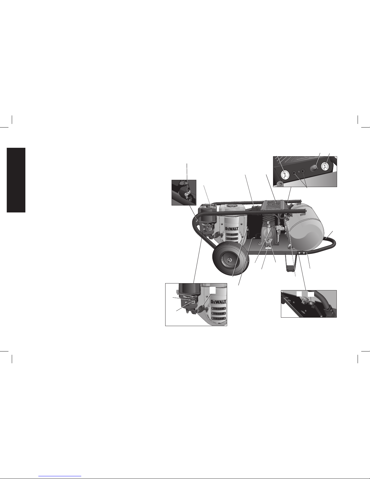
A. Pump Air Intake Filter
B. Engine Air Filter
C. Engine On/Off Switch
D. Air Tank Pressure Gauge
E. Regulated Pressure Gauge
F. Pressure Regulator
G. Air Outlet
H. Unloader Valve
I. Safety Valve
J. Air Tank Drain Valve
K. Throttle Control
Pump Specifi cations
Inline, vertical twin cylinder
Single stage
Oil lubricated
Cast iron crankcase and cylinder
Bore: 2.756" (70 mm)
Stroke: 2.26" (57.5 mm)
Weight: 46 lbs. (20.86 kg)
Oil Capacity: 24.7 oz. (730 mL)
D55684 Air Compressor
L. Pump Oil Dipstick
M. Pump Oil Drain Plug
N. Belt Tensioning Bolt
O. Low Oil Shut Down
P. Handle
Q. Handle Bracket
R. Fixed Throttle
S. Choke Control
T. Fuel Valve Lever
U. Starter Grip
Engine Specifi cations
DEWALT 196 cc
Internal Combustion
4-stroke
High RPM 3000 - 3200
Idle RPM 1800 - 2200
I
B
A
C
M
L
H
Q
P
FIG. 1
NOT A
STEP
N
J
O
K
R
S
T
U
200
180
160
140
120
100
80
60
40
20
E
F
D
G
Page 3
3
English
Specifi cations
MODEL WEIGHT HEIGHT WIDTH LENGTH
AIR TANK
CAPACITY
(GALLONS)
APPROX.
UNLOADER
RESET
PRESSURE
APPROX.
BLOW OFF
PRESSURE
TYPICAL VALUES
@ 100 PSI SCFM
D55684 185 lbs.
(83.9 kg)
22.3"
(566.4 mm)
24.2"
(614.68 mm)
50"
(1270 mm)
10.5
39.7 liters
120 PSI 150 PSI 10.5
Tested per
ISO 1217
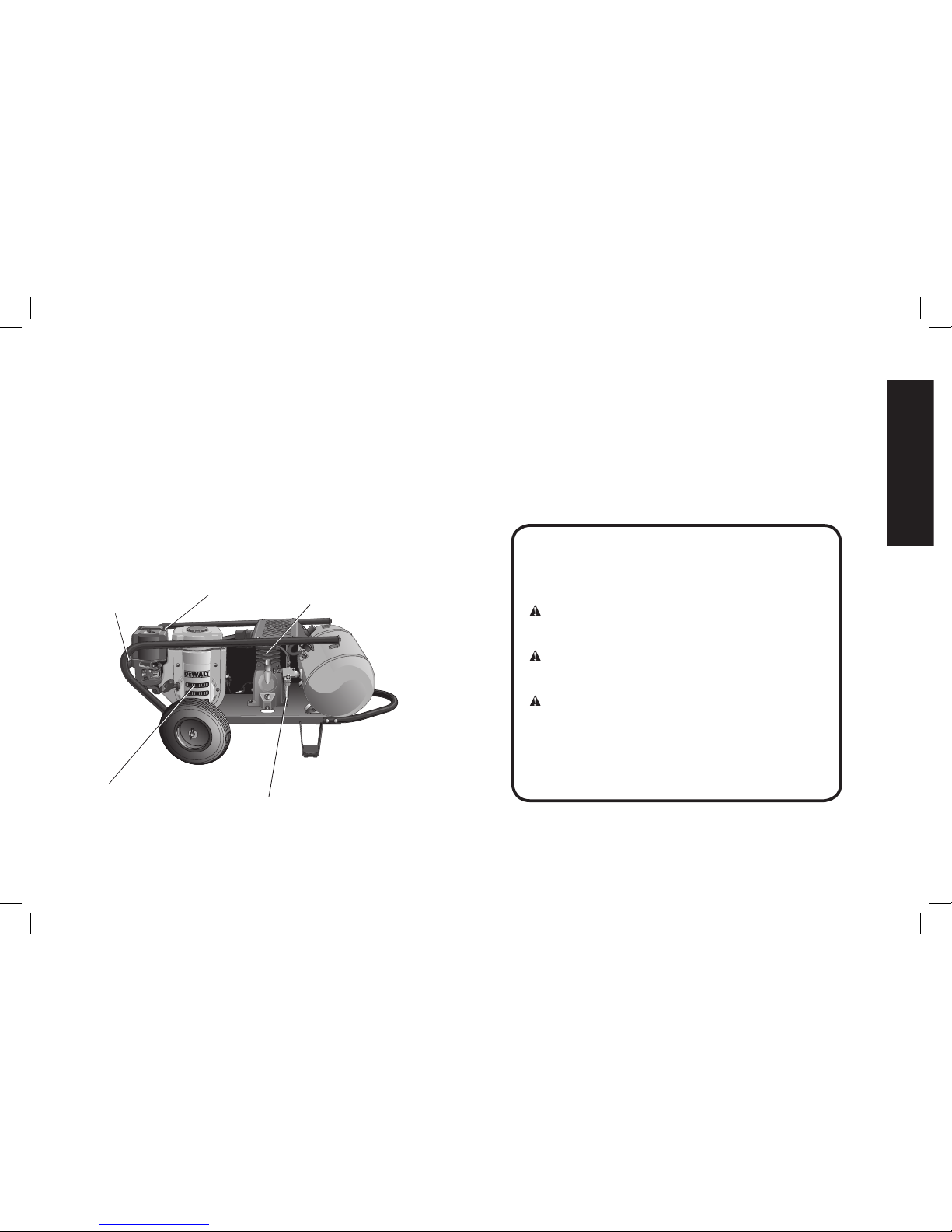
Hot Surfaces
Defi nitions: Safety Guidelines
The definitions below describe the level of severity
for each signal word. Please read the manual and
pay attention to these symbols.
DANGER: Indicates an imminently hazardous
situation which, if not avoided, will result in death
or serious injury.
WARNING: Indicates a potentially hazardous
situation which, if not avoided, could result in death
or serious injury.
CAUTION: Indicates a potentially hazardous
situation which, if not avoided, may result in minor
or moderate injury.
CAUTION: Used without the safety alert symbol
indicates a potentially hazardous situation which, if
not avoided, may result in property damage.
IF YOU HAVE ANY QUESTIONS OR COMMENTS ABOUT
THIS OR ANY D
E
WALT TOOL, CALL US TOLL FREE AT:
1-800-4-D
EWALT (1-800-433-9258)
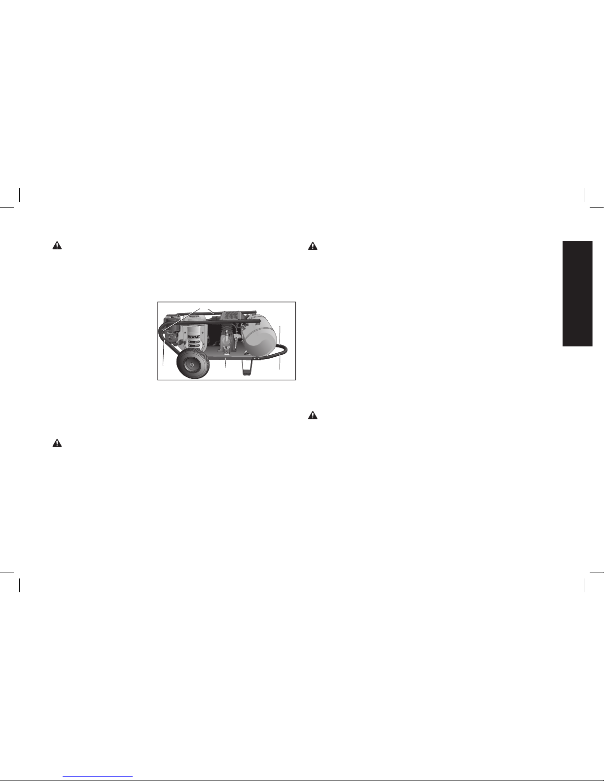
FIG. 2
PUMP CYLINDER
AND HEAD
CROSSOVER BAR
ENGINE
MUFFLER
GASOLINE
ENGINE
AFTERCOOLER
Page 4
4
English
IMPORTANT: These products are equipped with spark-arresting
mufflers. It is legally required in the state of California. It is a violation of California statutes section 130050 and/or sec tions 4442 and
4443 of the California Public Re sourc es Code, unless the engine
is equipped with a spark arrester, as defined in section 4442, and
maintained in ef fec tive work ing order. Spark arresters are also
required on some U.S. For est Service land and may also be legally
required under other statutes and or di nanc es.
SAVE THESE INSTRUCTIONS
DANGER: RISK OF EXPLOSION OR FIRE
WHAT CAN HAPPEN HOW TO PREVENT IT
• Spilled gas o line and it’s
vapors can be come ignited
from sparks from smoking
products, electrical arcing,
exhaust, flame, gas es and
other extremely hot surfaces.
• Shut off engine and allow it
to cool before removing cap
and adding fuel to the tank.
• Use care in filling tank to
avoid spilling fuel. Make sure
the cap is secure and move
unit away from fueling area
before starting engine.
• Add fuel outdoors in a well
ventilated area. Make sure
there are no sources of
ignition, such as
smoking
products
near refueling
location.
Important Safety Instructions
Important Safety Instructions
DANGER: Carbon Monoxide. Using an engine indoors can
kill you in minutes. Engine exhaust contains high levels of
carbon monoxide (CO), a poisonous gas you cannot see or
smell. You may be breathing CO even if you DO NOT smell
engine exhaust.
• NEVER use an engine inside homes, garages, crawlspaces, or
other partly enclosed areas. Deadly levels of carbon monoxide
can build up in these areas. Using a fan or opening windows and
doors does NOT supply enough fresh air.
• ONLY use outdoors and far away from open windows, doors
and vents. These openings can pull in engine exhaust.
• Even when the engine is used correctly, CO may leak into your
home. ALWAYS use a battery-powered or battery backup CO
alarm (not supplied) in the home. Read and follow all direc-
tions for CO alarm before using. If you start to feel sick, dizzy
or weak at anytime, move to fresh air immediately. See a doctor. You could have carbon monoxide poisoning.
WARNING: Do not operate this unit until you read and understand
this instruction manual and the tool instruction manual for safety,
operation and maintenance instructions.
WARNING: The engine exhaust from this product contains
chemicals known to the State of California to cause cancer, birth
defects or other reproductive harm. Wash hands after handling.
Page 5

5
English
• Heat will ex pand fuel in the
tank which could result in
spillage and pos si ble fire
explosion.
• Keep maximum fuel level
1/2" (12.7 mm) be low bottom
of filler neck to allow for
expansion.
• Combustible materials
and flammable vapors
which come into contact
with hot engine parts can
become ignited.
• Operate compressor in a
clean, dry, well ventilated
area a minimum of fortyeight inches from any building, object or wall. Do not
operate unit indoors or in
any confined area.
• Operate compressor in
an open area away from
dry brush, weeds or other
combustible materials or
flammable liquid
.
• Improperly stored fuel could
lead to acciden tal ignition.
Fuel im prop er ly secured
could get into the hands of
children or oth er un qual i fied
persons.
• Store fuel in an OSHAap proved con tain er, in a
se cure location away from
work area.
• Unattended operation
of this product could
result in personal injury
or property damage. To
reduce the risk of fire, do
not allow the compressor
to operate unattended.
• Always remain in attendance
with the product when it is
operating.
DANGER: RISK OF INJURY OR PROP ER TY DAMAGE WHEN
TRANSPORTING OR STORING
WHAT CAN HAPPEN HOW TO PREVENT IT
• Oil can leak or spill and could
result in fire or breathing
hazard; serious injury or
death can result. Oil leaks will
damage carpet, paint or other
surfaces in vehicles or trailers.
• Always place compressor
on a protective mat when
transporting to protect against
damage to vehicle from leaks.
Remove compressor from
vehicle immediately upon
arrival at your destination.
Always keep compressor level
and never lie on its side.
WARNING: RISK OF BURSTING
Air Tank: The air tank on your Air Compressor is designed and may
be UM coded (for units with air tanks greater than 6 inch diameter)
according to ASME Section VIII, Div. 1 rules. All pressure vessels
should be inspected once every two years. To find your state pressure
vessels inspector, look under the Division of Labor and Industries in
the government section of a phone book or call 1-800-4-
DEWALT
for
assistance.
The following conditions could lead to a weakening of the air tank, and
result in a violent air tank explosion:
Page 6

6
English
WHAT CAN HAPPEN HOW TO PREVENT IT
• Failure to properly drain
condensed water from
air tank, causing rust and
thinning of the steel air tank.
• Drain air tank daily or after each
use. If air tank develops a leak,
replace it immediately with a
new air tank or replace the
entire compressor.
• Modifications or attempted
repairs to the air tank.
• Never drill into, weld, or make
any modifications to the air
tank or its attachments. Never
attempt to repair a damaged or
leaking air tank. Replace with a
new air tank.
• Unauthorized modifications
to the unloader valve,
safety valve, or any other
components which control air
tank pressure.
• The air tank is designed
to withstand specific
operating pressures. Never
make adjustments or parts
substitutions to alter the factory
set operating pressures.
• Excessive vibration can
weaken the air tank and
cause rupture or explosion.
Excessive vibration will
occur if the compressor is
not properly mounted or
if engine operates above
recommended RPM.
• Do not remove the stiffener bar
connecting the compressor
pump to the engine, except
to adjust belt tension, Then
securely tighten the stiffener
bar bolts. This bar controls unit
vibration.
Attachments & accessories:
• Exceeding the pressure rating
of air tools, spray guns, air
operated accessories, tires,
and other inflatables can
cause them to explode or
fly apart, and could result in
serious injury.
• Follow the equipment
manufacturers recommendation
and never exceed the maximum
allowable pressure rating
of attachments. Never use
compressor to inflate small
low pressure objects such
as children’s toys, footballs,
basketballs, etc.
Tires:
• Over inflation of tires could
result in serious injury and
property damage.
• Use a tire pressure gauge to
check the tires pressure before
each use and while inflating
tires; see the tire sidewall for
the correct tire pressure.
NOTE: Air tanks, compressors and
similar equipment used to inflate
tires can fill small tires similar to
these very rapidly. Adjust pressure
regulator on air supply to no more
than the rating of the tire pressure.
Add air in small increments and
frequently use the tire gauge to
prevent over inflation.
Page 7
7
English
WARNING: RISK FROM FLYING OBJECTS
WHAT CAN HAPPEN HOW TO PREVENT IT
• The compressed air stream
can cause soft tissue damage
to exposed skin and can
propel dirt, chips, loose
particles, and small objects
at high speed, resulting in
property damage or personal
injury.
• Always wear certified safety
equipment: ANSI Z87.1 eye
protection (CAN/CSA Z94.3)
with side shields when using
the compressor.
• Never point any nozzle or
sprayer toward any part of
the body or at other people or
animals.
• Always turn the compressor off
and bleed pressure from the
air hose and air tank before
attempting maintenance,
attaching tools or accessories.
DANGER: RISK TO BREATHING (ASPHYXIATION)
WHAT CAN HAPPEN HOW TO PREVENT IT
• Breathing ex haust fumes
can cause se ri ous injury or
death!
Engine exhaust contains high levels of carbon
monoxide (CO), a poisonous gas you cannot see or
smell. You may be breathing CO even if you do not
smell engine exhaust.
• NEVER use an engine inside
homes, garages, crawlspaces
or other partly enclosed
areas. Deadly levels of carbon
monoxide can build up in
these areas. Using a fan or
opening windows and doors
does NOT supply enough
fresh air.
• Only use outdoors and far
away from open windows,
doors and vents. These
openings can pull in engine
exhaust.
•
Keep children, pets and others
away from area of operation.
• Always keep the exhaust
manifold free of foreign
objects.
Page 8
8
English
• The compressed air directly
from your compressor is not
safe for breathing. The air
stream may contain carbon
monoxide, toxic vapors,
or solid particles from the
air tank. Breathing these
contaminant's can cause
serious injury or death.
• Air obtained directly from the
compressor should never be
used to supply air for human
consumption. In order to use air
produced by this compressor
for breathing, suitable filters and
in-line safety equipment must
be properly installed. In-line
filters and safety equipment
used in conjunction with the
compressor must be capable
of treating air to all applicable
local and federal codes prior to
human consumption.
• Sprayed materials such as
paint, paint solvents, paint
remover, insecticides, weed
killers, may contain harmful
vapors and poisons.
• Work in an area with good
cross ventilation. Read and
follow the safety instructions
provided on the label or safety
data sheets for the materials
you are spraying. Always use
certified safety equipment:
NIOSH/OSHA respiratory
protection designed for use with
your specific application.
WARNING: RISK OF HOT SURFACES
WHAT CAN HAPPEN HOW TO PREVENT IT
• Touching exposed metal such
as the compressor head,
engine head, engine exhaust
or outlet tubes, can result in
serious burns.
• Never touch any exposed
metal parts on compressor
during or immediately after
operation. Compressor will
remain hot for several minutes
after operation
• Do not reach around
protective shrouds or attempt
maintenance until unit has
been allowed to cool.
WARNING:
RISK FROM MOVING PARTS
WHAT CAN HAPPEN HOW TO PREVENT IT
• The engine can start
accidentally if the flywheel is
turned by hand or moved by
pulling on the starter rope.
• Always disconnect the spark
plug and bleed pressure from
the air tank before performing
maintenance.
Page 9

9
English
• Moving parts such as the
pulley, flywheel, and belt can
cause serious injury if they
come into contact with you or
your clothing.
• Never operate the compressor
with guards or covers which are
damaged or removed.
• Keep your hair, clothing, and
gloves away from moving parts.
Loose clothes, jewelry, or long
hair can be caught in moving
parts.
• Air vents may cover moving
parts and should be avoided as
well.
• Attempting to operate
compressor with damaged or
missing parts or attempting
to repair compressor with
protective shrouds removed
can expose you to moving
parts and can result in serious
injury.
• Any repairs required on this
product should be performed
by a
DEWALT factory
service center or a D
EWALT
authorized service center
WARNING: RISK OF UNSAFE OPERATION
WHAT CAN HAPPEN HOW TO PREVENT IT
• Unsafe op er a tion of your air
compressor could lead to se rious in ju ry or death to you or
others.
• Review and understand all
instructions and warnings in
this manual.
• Be come fa mil iar with the op era tion and con trols of the air
compressor.
• Keep operating area clear of all
persons, pets, and obstacles.
• Keep chil dren away from the
air compressor at all times.
• Do not operate the product
when fatigued or under the
influence of alcohol or drugs.
Stay alert at all times.
• Never defeat the safety features of this prod uct.
• Equip area of operation with a
fire extinguisher.
• Do not op er ate machine with
missing, broken, or un au thorized parts.
• Never stand on the
compressor.
Page 10
10
English
WARNING: RISK OF
INJURY FROM LIFTING
WHAT CAN HAPPEN HOW TO PREVENT IT
• Serious injury can result
from attempting to lift too
heavy an object.
• The compressor is too heavy
to be lifted by one person.
Obtain assistance from others
before lifting.
CAUTION: RISK FROM NOISE
WHAT CAN HAPPEN HOW TO PREVENT IT
•
Under some conditions and
duration of use, noise from
this product may contribute
to hearing loss.
• Always wear certified safety
equipment: ANSI S12.6
(S3.19) hearing protection.
SAVE THESE INSTRUCTIONS
FOR FUTURE USE
FEATURES
UNLOADER VALVE
When the maximum air tank pressure is obtained, the unloader
valve (H) will blow-off. This will cause the compressor to exhaust
the air to the atmosphere and not the tank. The valve is preset by the
manu facturer and must not be removed or modified in any way.
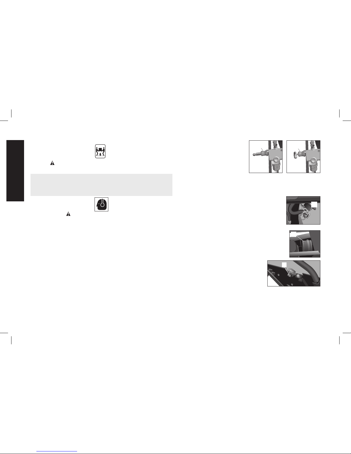
Manual Lock: The manual lock allows you to manually unload the
compressor with air pressure in the air tank. To operate the manual
lock:
Rotate the manual lock unloader
OPEN
CLOSED
H
H
lever to the open position to
prevent air tank pressure buildup.
Rotate manual lock unloader lever
to the closed position after
starting the engine to allow air
tank pressure to build. NOTE: Air
will not build in tank when manual lock unloader lever in the open
position.
SAFETY VALVE
This valve (I) is designed to prevent system failures
I
by relieving pressure from the system when the
compressed air reaches a predeter mined level. The
valve is preset by the manu facturer and must not be
removed or modified in any way.
AIR INTAKE FILTER
The filter (A) is designed to clean air entering the pump.
A
To ensure the pump continually receives a clean, cool,
and dry air supply the filter must always be clean and
the filter intake must be free from obstructions.
AIR TANK DRAIN VALVE
The drain valve (J) is used to remove
J
moisture from the air tank after the air
compressor is shut off.
AIR TANK PRESSURE GAUGE
The air tank pressure gauge (D) indicates
air pressure in the air tank.
Page 11
11
English
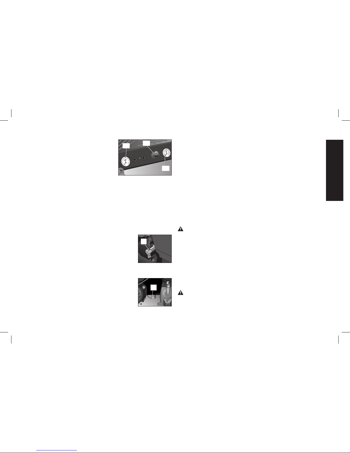
REGULATED PRESSURE GAUGE
The regulated pressure gauge (E) indicates
20
0
1
80
1
60
140
120
1
0
0
80
60
40
20
E
F
D
the air pressure available at the outlet side
of the regulator. This pressure is controlled
by the regulator and is always less or equal
to the air tank pressure.
REGULATOR
The regulator knob (F) controls the air pressure coming from the air
tank.
Adjusting Regulator
1. Pull regulator knob (F) out to unlock.
2. Turn knob clockwise to increase regulated pressure and
counterclockwise to decrease regulated pressure.
3. When desired pressure is shown on the regulated pressure
gauge push knob in to lock.
THROTTLE CONTROL
When maxi mum air tank pres sure is reached and
K
the unloader valve vents air, it activates the throttle
control (K) on the engine. This gas saving feature
holds the engine at a factory-set idling speed until
air pressure in the air tank drops to reset pressure.
The unloader valve then reactivates the throttle
control and accelerates the engine to full throttle.
LOW OIL SHUT DOWN SENSORS
The air compressor engine and pump are equipped
O
with low oil shutdown sensors (O). These are
safety devices designed to protect your engine and
pump from damage in the event the oil level in the
crankcase is below minimum.
If the oil in the pump or engine gets low while the air compressor is
running it will automatically shut down the engine and will not restart
until oil is added to the engine or pump. If the oil is low before startup, the engine will not start until oil is added.
NOTE: The low oil shutdown sensors are very sensitive. You
must fill the engine and pump to the full mark on the dipstick to
inactivate this safety device.
INSTALLATION
Assembly (Fig. 1)
HANDLE
Assembly handle (P) to handle bracket (Q) using hardware supplied.
The nuts supplied will not spin onto bolts, after two turns a wrench,
ratchet, or air tool needs to be used to tighten securely.
INSTALLING HOSES
WARNING: Risk of unsafe operation. Firmly grasp hose in hand
when installing or disconnecting to prevent hose whip.
1. Ensure regulated pressure gauge reads 0 PSI.
2. Apply sealant tape to hose threads.
3. Assemble hose(s) to air outlet(s) (G). IMPORTANT: Do not
assemble splitters directly to the air outlet(s) (G).
NOTE: Assembling quick connect bodies to air outlets (G) and quick
connect plugs to hose ends make connecting and disconnecting
hoses simple and easy. Quick connect bodies and plugs are available
for purchase from your local dealer or authorized service center.
DISCONNECTING HOSES
WARNING: Risk of unsafe operation. Firmly grasp hose in hand
when installing or disconnecting to prevent hose whip.
1. Ensure regulated pressure gauge reads 0 PSI.
2. Remove hose(s) from air outlet(s) (G).
Page 12

12
English
Lubrication and Oil
ENGINE
1. The engine was filled WITH oil at the manufacturer. Check
engine oil level before operating unit. If necessary, fill engine
to the appropriate level with recommended oil, see engine's
instruction manual supplied by engine manufacturer for correct
procedure.
2. Add fuel to engine. See engine's instruction manual supplied by
engine manufacturer for correct procedure.
WARNING: Risk of explosion or fire. Gasoline vapor is highly
flammable. Refuel outdoors preferably, or only in well-ventilated
areas. Do not refuel or check gasoline level while the engine is
running. Do not store, spill, or use gasoline near an open flame,
a source of sparks (such as welding), or near operating electrical
equipment.
AIR COMPRESSOR
The air compressor pump was filled WITH oil at the manufacturer.
Check air compressor pump oil level before operating unit. See
Compressor Pump Oil under Maintenance.
Compatibility
Air tools and accessories that are run off the compressor must be
compatible with petroleum based products. If you suspect that a
material is not compatible with petroleum products, an air line filter
for removal of moisture and oil vapor in compressed air is required.
NOTE: Always use an air line filter to remove moisture and oil vapor
when spraying paint.
Location
WARNING: Risk of breathing. Exhaust from the gasoline engine
contains deadly carbon monoxide, which is odorless and toxic.
Operate engine only in well ventilated areas.
CAUTION: Risk of property damage. In order to avoid damaging
the air compressor, do not allow the unit to be tilted more than 10º
when operating.
Place air compressor at least 4 feet (1.2 m) away from obstacles that
may prevent proper ventilation. Keep unit away from areas that have
dirt, vapor and volatile fumes in the atmosphere which may clog and
gum up the intake filter and valves, causing inefficient operation.
HUMID AREAS
In frequently humid areas, moisture may form in the pump and
produce sludge in the oil, causing running parts to wear out
prematurely. Excessive moisture is especially likely to occur if the unit
is located in an unheated area that is subject to large temperature
changes. Two signs of excessive humidity are external condensation
on the pump when it cools down and a “milky” appearance in
compressor oil. You may be able to prevent moisture from forming in
the pump by increasing ventilation or operating for longer intervals.
NOISE CONSIDERATIONS
Consult local officials for information regarding acceptable noise
levels in your area. To reduce excessive noise, use vibration mounts
or silencers, relocate the unit or baffle walls. Contact a D
E
WALT
service center or call 1-800-4-D
E
WALT for assistance.
TRANSPORTING
WARNING: Risk injury from lifting. Unit weighs more than 160 lbs.
(72.6 kg) Do not move or lift without assistance.
Page 13
13
English
CAUTION: Risk of property damage. The wheels and handle do
not provide adequate clearance, stability or support for pulling the
unit up and down stairs or steps. The unit must be lifted, or pushed
up a ramp.
CAUTION:
Risk of property damage.
Place engine fuel valve lever
(T) in the OFF position before moving or transporting unit.
When transporting the
W
V, W
P
V, W
V
compressor in a vehicle,
trailer, etc. ensure that the
air tank is drained and the
unit is secured and placed
on a protective mat on a flat
horizontal surface. DO NOT
transport in a standing
position. NOTE: Use
recommended tie down points (V) when transporting. Use care
when driving so to avoid tipping the unit over in the vehicle. Damage
can occur to the unit or surrounding items if unit is tipped. Use a
ramp if loading or unloading the unit from a height of more than 12"
(30.5 cm).
LIFTING
WARNING: Risk injury from lifting. Unit weighs more than 160 lbs.
(72.6 kg) Do not move or lift without assistance.
CAUTION:
Risk of property damage.
Place engine fuel valve lever
(T) in the OFF position before moving or transporting unit.
Always use two people when lifting and lift from the recommended
lift points (W).
MOVING
1. Grasp handle (P) of compressor, and lift compressor high
enough so unit can be rolled on the front tires.
WARNING: Risk of unsafe operation. Ensure proper footing and
use caution when rolling compressor so that unit does not tip or
cause loss of balance.
CAUTION:
Risk of property damage.
Place engine fuel valve lever
(T) in the OFF position before moving or transporting unit.
2. When location is reached slowly lower rear of compressor
to ground. Always store compressor in a horizontal position.
NOTE: DO NOT store in a standing position.
NOTE: Should the unit tip over, hard starting and smoking will occur
due to oil spillage.
General Requirements
The piping, fittings, receiver tank, etc. must be certified safe for at
least the maximum working pressure of the unit. Use hard welded
or threaded steel or copper pipes, cast iron fittings and hoses that
are certified safe for the units discharge pressure and temperature.
Use pipe thread sealant on all threads, and tighten joints thoroughly
to prevent air leaks. DO NOT USE PVC PLASTIC.
WARNING: Risk of bursting. Plastic or PVC pipe is not designed
for use with compressed air. Regardless of its indicated pressure
rating, plastic pipe can burst from air pressure. Use only metal pipe
for air distribution.
CONDENSATE DISCHARGE PIPING
If installing a condensate discharge line, the piping must be at least
one size larger than the connection, as short and direct as possible,
secured tightly and routed to a suitable drain point. Condensate
must be disposed of in accordance with local, state and federal laws
and regulations.
Page 14

14
English
NOTE: All compressed air systems generate condensate that
accumulates in any drain point (e.g., tank, filter, aftercoolers, dryers).
This condensate contains oil and/or substances which may be
regulated and must be disposed of in accordance with local, state,
and federal laws and regulations.
PREPARATION FOR USE
Pre-Start Checklist
1. Ensure engine ON/OFF switch (C) is in the OFF Position.
2. Ensure air tank is drained, see Draining Air Tank under
Maintenance.
3. Ensure the drain valve (J) is closed.
4. Ensure safety valve (I) is functioning properly, see Checking
Safety Valve under Maintenance.
5. Check pump oil level, see Compressor Pump Oil under
Maintenance.
CAUTION:
Do not operate without oil or with inadequate oil. DEWALT
is not responsible for compressor failure caused by inadequate oil.
6. Check engine's oil and fuel level, see engine's instruction manual
for correct procedures.
7. Visually inspect drive belt. Replace belt if frayed, cracked, or worn.
NOTE: Outer belt cover must be removed to inspect drive belt.
8. Ensure all guards, covers, and labels are in place, legible (for
labels) and securely mounted. Do not use compressor until all
items have been verified.
Initial Set-up (Fig. 1)
Read safety instructions before setting-up air compressor.
BREAK-IN PROCEDURE
WARNING: Risk of property damage. Serious damage may result
if the following break-in instructions are not closely followed.
This procedure is required:
• Before the air compressor is used for the first time.
• When the unloader valve has been replaced.
• When the compressor pump has been replaced.
The procedure:
1. Follow Pre-Start Checklist under Preparation for Use.
2. Rotate the unloader's manual lock to the open position to
prevent air tank pressure buildup.
3. Open the pressure regulator. Pull regulator knob (F) out and
rotate clockwise until it stops.
WARNING: Do not operate this unit until you read and understand
the engine instruction's manual for safety, operation and maintenance
instructions.
4. Prepare engine for first time use, see engine's instruction manual
for correct procedure.
5. Turn the engine ON/OFF switch (C) to the ON position.
6. Place the fuel valve lever (T) in the
OPEN
CLOSED
S
T
OFF
ON
ON postion.
7.
If the engine is cold, move the
choke (S) to the CLOSED position
as shown. If the engine is hot, move
the choke to the OPEN position.
WARNING: Risk of unsafe opera-
tion. Pull starter grip slowly until resistance is felt. Then pull starter grip (P) rapidly to avoid kickback and
prevent hand or arm injury.
NOTE: Do not allow the starter grip to snap back. Return it gently
by hand.
NOTE: If the oil level in the engine is low, the engine will not start.
If the engine does not start, check the oil level and add oil as
needed.
Page 15

15
English
NOTE: To ensure maximum oil lubrication, place the unit on a level
surface.
9. As the engine warms up, move the choke to the OPEN position.
10. Run the air compressor for 30 minutes to seat the rings and
lubricate all the internal surfaces. Ensure there is no pressure
build up in the air tank by observing the reading on the air tank
pressure gauge.
11. Rotate the manual lock on the unloader valve into the closed
position so the air tank pressure can build.
12. Close the pressure regulator. Rotate the regulator knob (F)
counterclockwise to its built-in stop and push knob in to lock in
place. This will allow air to build pressure in the air tank.
13. Compressed air will be available from the hose air outlet until it is
used up or bled off.
OPERATING PROCEDURES
Start-up (Fig. 1)
1. Follow Pre-Start Checklist under Preparation for Use.
2. Pull out and turn regulator knob (F) counterclockwise until fully
closed. Push in to lock. Regulated pressure gauge should read
0 PSI.
3. Rotate the manual lock unloader lever to the open position to
assist with start up.
4. Turn the engine ON/OFF switch (C) to the ON Position.
5. Place the fuel valve lever (T) in the ON postion.
6.
If the engine is cold, move the choke (S) to the CLOSED position
as shown. If the engine is hot, move the choke to the OPEN
position.
WARNING: Risk of unsafe operation. Pull starter grip slowly until
resistance is felt. Then pull starter grip (P) rapidly to avoid kickback
and prevent hand or arm injury.
NOTE: Do not allow the starter grip to snap back. Return it gently
by hand.
NOTE: If the oil level in the engine is low, the engine will not start.
If the engine does not start, check the oil level and add oil as
needed.
NOTE: To ensure maximum oil lubrication, place the unit on a level
surface.
8. As the engine warms up, move the choke to the OPEN position.
9. Rotate manual lock unloader lever to the closed position to allow
air tank pressure to build. NOTE: Pump will not operate with the
manual lock unloader lever in the open position.
10. Allow compressor to pump up to blow off pressure.
WARNING: Risk of unsafe operation. If any unusual noise
or vibration is noticed, stop the compressor and refer to the
troubleshooting section.
NOTE: The air compressor pump is capable of running continuously.
To prolong the air compressor's life, it is recommended to run at high
throttle 50-75% of the run time and idle for 25% of the run time
11. Attach hose and accessory.
WARNING: Risk of unsafe operation. Firmly grasp hose in hand
when installing or disconnecting to prevent hose whip.
WARNING:
Risk of unsafe operation. Do not use damaged or worn
accessories.
CAUTION: Risk of unsafe operation. Compressed air from the unit
may contain wa ter condensation and oil mist. Do not spray un fil tered
air at an item that could be damaged by moisture. Some air op er ated
tools or de vic es may require filtered air. Read the in struc tions for the
air tool or device.
12. Adjust regulator (F) to desired setting. See Regulator under
Features.
Page 16

16
English
Shut-down
1. Place the engine ON/OFF switch (C) to the OFF Position.
2. Place the fuel valve lever (T) in the OFF postion.
NOTE: If finished using compressor, follow Steps 3–7.
3. Turn regulator knob (F) counterclockwise until fully closed. Ensure
regulated pressure gauge reads 0 PSI.
4. Remove hose and accessory.
5. Drain the air tank. Ensure air tank pressure gauge reads 0 PSI.
CAUTION:
Risk of property damage.
Place engine fuel valve lever
(T) in the OFF position before moving or transporting unit.
WARNING: Risk of bursting. Drain air tank daily. Water will condense
in air tank. If not drained, water will corrode and weaken the air tank
causing a risk of air tank rupture.
6. Allow the compressor to cool down.
7 . Wipe air compressor clean and store in a safe, non freezing area.
MAINTENANCE
WARNING:The following procedures must be followed when
maintenance or service is performed on the air compressor.
1. Ensure engine ON/OFF switch (C) is in the OFF position.
2. Disconnect spark plug wire.
3. Drain air tank.
4. Allow air compressor to cool down before starting service
NOTE: All compressed air systems contain maintenance parts (e.g.
oil, filters, separators) that are periodically replaced. These used parts
may contain substances that are regulated and must be disposed of in
accordance with local, state, and federal laws and regulations.
NOTE: Take note of the positions and locations of parts during
disassembly to make reassembly easier.
NOTE: Any service operations not included in this section should
be performed by a D
EWALT factory service center or a DEWALT
authorized service center.
Maintenance Chart
Procedure Daily Weekly Monthly 1 year or
200 Hours
Check safety valve
X
Inspect air filter
+
X
Drain air tank
X
Check pump oil level
X
Change pump oil**
+
X
Oil leak inspection
X
Inspect drive belt
X
Check drive belt tension
X
Check pulley/flywheel
alignment
X
Check for unusual noise/
vibration
X
Check for air leaks*
X
Clean compressor exterior
X
Engine See engine instruction manual.
* To check for air leaks apply a solution of soapy water around joints. While
compressor is pumping to pressure and after pressure cuts out, look for
air bubbles to form.
** The pump oil must be changed after the first 20 hours or operation.
Thereafter, when using
DEWALT
synthetic compressor oil, change oil
every 200 hours of operation or once a year, whichever comes first.
+ Perform more frequent in dusty or humid conditions.
Page 17

17
English
Checking Safety Valve (Fig. 1)
WARNING: Hot surfaces. Risk of burn. Aftercooler, pump head,
and surrounding parts are very hot, do not touch (see the Hot
Surfaces identified in Fig. 2). Allow compressor to cool prior to
servicing.
WARNING: Risk of bursting. If the safety valve does not work
properly, over-pressurization may occur, causing air tank rupture or
an explosion.
1. Ensure engine ON/OFF switch (C) is in the OFF Position.
2. Ensure air tank pressure gauge reads 0 PSI. Drain air tank if
necessary.
3. Grasp wire ring on safety valve (I).
4. Pull and release ring a few times to ensure plunger moves in
and out.
Checking Air Filter Element (Fig. 1)
WARNING: Hot surfaces. Risk of burn. Aftercooler, pump head,
and surrounding parts are very hot, do not touch (see the Hot
Surfaces identified in Fig. 2). Allow compressor to cool prior to
servicing.
1. Ensure engine ON/OFF switch (C) is in the OFF Position.
2. Allow unit to cool.
3. Unscrew filter (A) top from filter base by turning counterclockwise about 5 degrees.
4. Separate filter top from base.
5. Remove element from filter base.
6. If element needs cleaning, blow out with air. Replace if needed.
Purchase replacement parts from your local dealer or authorized
service center. Always use identical replacement parts.
7. Place element back in filter base.
8. Reconnect filter top to filter base. While pushing in, rotate clockwise 5 degrees.
CAUTION: Risk of unsafe operation. Do not operate without air
inlet filter.
Draining Air Tank (Fig. 1)
WARNING: Risk of unsafe operation. Risk from noise. Air tanks
contain high pressure air. Keep face and other body parts away from
outlet of drain. Use eye protection [ANSI Z87.1 (CAN/CSA Z94.3)]
when draining as debris can be kicked up into face.
WARNING: Risk from noise. Use ear protection [ANSI S12.6
(S3.19)] as air flow noise is loud when draining.
NOTE: All compressed air systems generate condensate that
accumulates in any drain point (e.g., tanks, filter, aftercoolers,
dryers). This condensate contains lubricating oil and/or substances
which may be regulated and must be disposed of in accordance with
local, state, and federal laws and regulations.
1. Ensure engine ON/OFF switch (C) is in the OFF Position.
2. Move compressor into an inclined position so drain valve (J) is
at the lowest point (this will assist in removing moisture, dirt, etc.
from air tanks)
3. Place a suitable container under the drain valve to
catch discharge.
4. Grasp black lever on drain valve.
5. Slowly rotate lever to gradually bleed air from air tank.
WARNING: Risk of bursting. Drain air tank daily. Water will con-
dense in air tank. If not drained, water will corrode and weaken the
air tank causing a risk of air tank rupture.
CAUTION: Risk of Property Damage. Drain water from air tank
may contain oil and rust which can cause stains.
6. When air tank pressure gauge reads 10 PSI, rotate valve to the
fully open position.
7. Close drain valve when finished.
Page 18
18
English
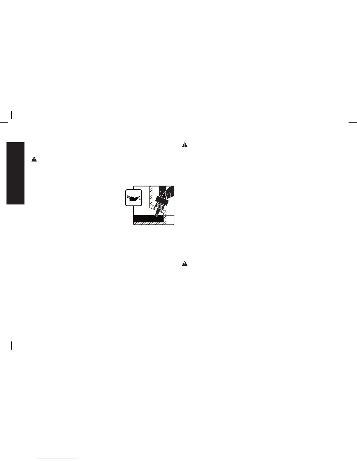
Compressor Pump Oil (Fig. 1)
CHECKING OIL
WARNING: Hot surfaces. Risk of burn. Aftercooler, pump head,
and surrounding parts are very hot, do not touch (see the Hot
Surfaces identified in Fig. 2). Allow compressor to cool prior to
servicing.
1. Ensure engine ON/OFF switch (C) is in the OFF Position.
2. Place unit on a flat level surface.
3. Remove dipstick (L) and wipe clean.
4. Insert and remove dipstick without
MAX.
OIL
MIN.
threading dipstick into crankcase as
shown in figure.
5. Check the oil level on dipstick.
If oil level is at or below “Add”,
oil needs to be added. Add D
EWALT
synthetic oil to the proper maximum level as shown in figure.
NOTE: When filling the crankcase, the oil flows very slowly into the
pump. If the oil is added too quickly, it will overflow and appear to
be full.
NOTE: The low oil shutdown sensors are very sensitive. You
must fill the engine and pump to the full mark on the dipstick to
inactivate this safety device.
CAUTION: Risk of property damage. Overfilling with oil will cause
premature compressor failure. Do not overfill.
6. Replace dipstick and tighten securely.
CHANGING OIL
NOTE: Pump oil contains substances that are regulated and must
be disposed of in accordance with local, state and federal laws and
regulations.
WARNING: Hot surfaces. Risk of burn. Aftercooler, pump
head, and surrounding parts are very hot, do not touch (see the
Hot Surfaces identified in Fig. 2). Allow compressor to cool prior
to servicing.
1. Ensure engine ON/OFF switch (C) is in the OFF Position.
2. Allow the unit to cool.
3. Disconnect spark plug wire.
4. Drain air tank.
5. Locate a suitable container under pump drain plug (J).
6. Remove the dipstick (L) from crank case.
7. Remove the oil drain plug (M).
8. Allow ample time for all oil to drain out. (Tilting the compressor
towards the drain plug will assist in draining.)
9. Install the oil drain plug.
10. Fill pump with D
EWALT synthetic compressor oil. Oil should not
exceed top raised line on side of crackcase. (Oil will be even with
bottom of threads in crankcase fill port.)
11. Install dipstick.
12. Reconnect spark plug wire.
Checking Belt Tension (Fig. 1)
WARNING: Hot surfaces. Risk of burn. Aftercooler, pump head,
and surrounding parts are very hot, do not touch (see the Hot
Surfaces identified in Fig. 2). Allow compressor to cool prior to
servicing.
1. Ensure engine ON/OFF switch (C) is in the OFF Position.
2. Allow the unit to cool.
3. Disconnect spark plug wire.
4. Drain air tank.
5. Remove eight belt guard screws.
Page 19
19
English
6. Remove outer belt cover.
7. Measure belt tension. Proper tension is achieved when a three
(3) pound weight or equivalent finger pressure applied midway
between the motor pulley and compressor flywheel causes a
1/4" (6.35 mm) deflection of the belt., if adjustment is needed
see Adjusting Belt Tension under Maintenance.
8. Replace belt guard.
9. Reconnect spark plug wire.
Adjusting Belt Tension
WARNING: Hot surfaces. Risk of burn. Aftercooler, pump head,
and surrounding parts are very hot, do not touch (see the Hot
Surfaces identified in Fig. 2). Allow compressor to cool prior
to servicing.
1. Ensure engine ON/OFF switch (C) is in the OFF position.
2. Allow the unit to cool.
3. Disconnect spark plug wire.
4. Drain air tank
5. Loosen but do not remove four pump mounting bolts.
6. Remove eight belt cover screws.
7. Remove outer belt cover.
8. Loosen but do not remove pump stiffener
X
bracket bolt (X).
9. Turn belt tensioning (N) bolt
clockwise to increase belt tension or
counterclockwise to loosen belt tension.
10. Check the belt tension again. See Step
7 in Checking Belt Tension under
Maintenance.
11. When tension is correct, retighten four
N
pump mounting bolts (torque to
18– 22 ft.- lbs./24.4–29.8 Nm), stiffener
bracket bolt (torque to 18– 22 ft.- lbs./
24.4– 29.8 Nm), and replace belt cover.
12. Reconnect spark plug wire.
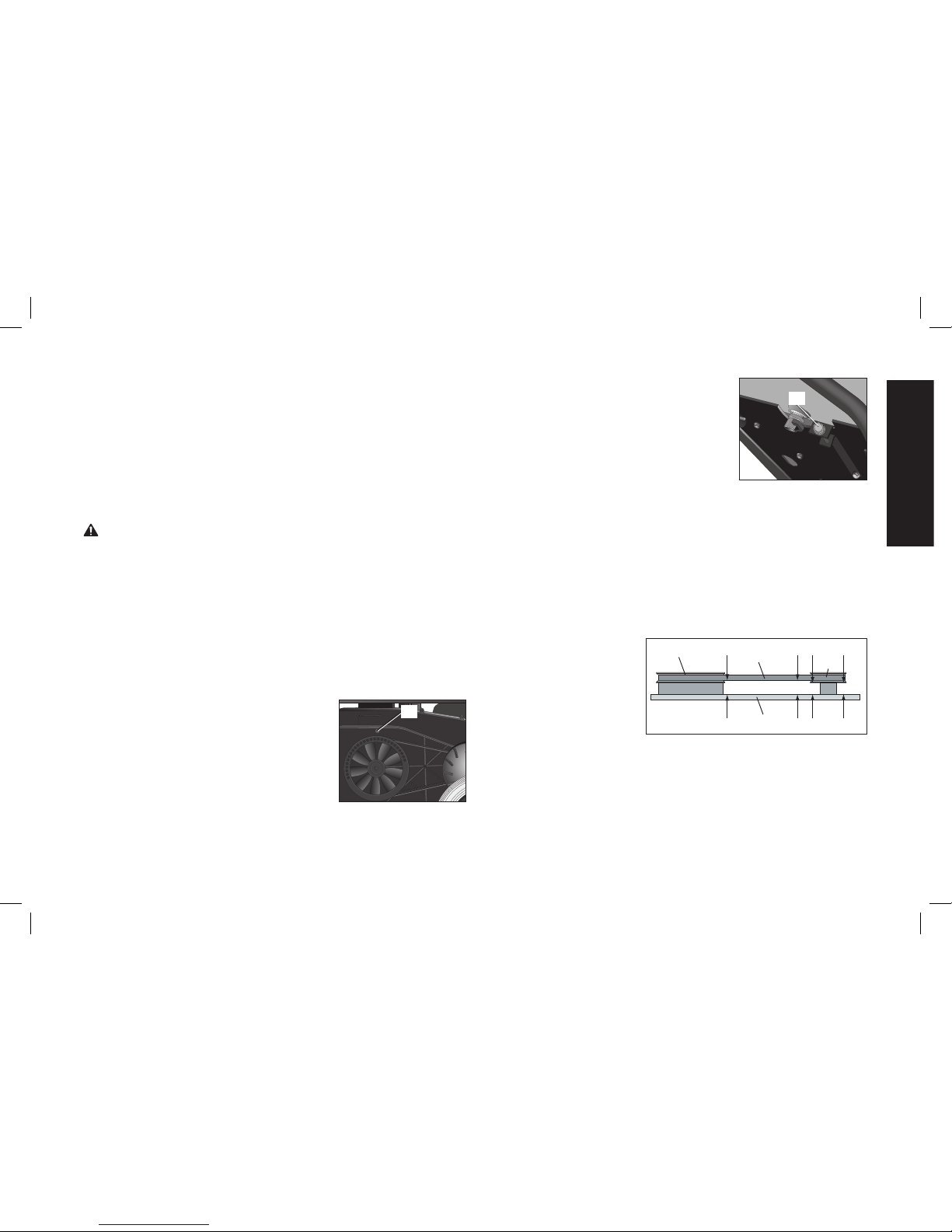
Pulley and Fly wheel
Alignment
The air compressor flywheel and engine pulley must be in-line (in
the same plane) within 1/16" (1.6 mm) to ensure belt retention within
flywheel belt grooves. To check alignment:
1. Ensure engine ON/OFF switch (C) is in the OFF Position.
2. Allow the unit to cool.
3. Disconnect spark plug wire.
4. Drain air tank.
5. Remove outer belt cover.
6. Place a straightedge
A1
Y
Z
A3
A3
A4
A4 A5 A6
A5 A6
A2
(Y) against the outside
of the flywheel (Z) and
the engine drive pulley
(A1).
7. Measure the distance
between the edge of
the belt (A2) and the straightedge at points A3 and A4 in Figure.
The difference between mea sure ments should be no more than
1/16" (1.6 mm).
8. If the difference is greater than 1/16" (1.6 mm), loosen the
setscrew holding the engine drive pulley to the shaft and adjust
the pulley's position on the shaft until the A3 and A4 mea surements are within 1/16" (1.6 mm) of each other.
Page 20

20
English
9. Tighten the engine drive pulley setscrew to 140–150 in.-lbs.
(15.42–16.95 Nm).
10. Visually inspect the engine drive pulley to verify that it is
perpendicular to the drive motor shaft. Points A5 and A6 of Figure
should appear to be equal. If they are not, loos en the setscrew of
the engine drive pulley and equal ize A5 and A6, using care not to
disturb the belt align ment per formed in Step 8.
11. Retighten the engine drive pulley set screw to 140–150 in.-lbs.
(15.42–16.95 Nm).
12. Reinstall belt guard.
13. Reconnect spark plug wire.
ACCESSORIES
Recommended accessories for use with your tool are available
for purchase from your local dealer or authorized service center.
If you need assistance in locating any accessory for your tool,
please contact D
E
WALT Industrial Tool Co., 701 East Joppa Road,
Baltimore, MD 21286, call 1-800-4-D
EWALT (1-800-433-9258) or
visit our website www.dewalt.com.
WARNING: The use of any other accessory not recommended for
use with this tool could be hazardous. Use only accessories rated
equal to or higher than the rating of the air compressor.
SERVICE INFORMATION
Please have the following information available for all service calls:
Model Number ____________ Serial Number ___________
Date and Place of Purchase ____________________________
Repairs
To assure product SAFETY and RELIABILITY, repairs, maintenance
and adjustment should be performed by a D
E
WALT factory service
center, a D
E
WALT authorized service center or other qualified service
personnel. Always use identical replacement parts.
Full One Year Warranty
DEWALT heavy duty industrial tools are warranted for one year from
date of purchase. We will repair, without charge, any defects due
to faulty materials or workmanship. For warranty repair information,
call 1-800-4-D
E
WALT. This warranty does not apply to accessories
or damage caused where repairs have been made or attempted by
others. This warranty gives you specific legal rights and you may
have other rights which vary in certain states or provinces.
LATIN AMERICA: This warranty does not apply to products sold
in Latin America. For products sold in Latin America, see country
specific warranty information contained either in the packaging, call
the local company or see website for warranty information.
FREE WARNING LABEL REPLACEMENT: If your warning labels
become illegible or are missing, call 1-800-4-D
E
WALT for a free
replacement.
A20550
DO NOT STORE OR OPERATE
IN UPRIGHT POSITION.
NO LO GUARDE NI OPERE
EN POSICIÓN VERTICAL.
NEPAS RANGER NI UTILISERL'APPAREIL
EN POSITION VERTICALE.
Page 21

21
English
GLOSSARY
CFM: Cubic feet per minute.
SCFM: Standard cubic feet per minute; a unit of measure of air delivery.
PSIG: Pounds per square inch gauge; a unit of measure of pressure.
Code Certification: Products that bear one or more of the following marks: UL, CUL, ETL, CETL, have been evaluated by OSHA
certified independent safety laboratories and meet the applicable Underwriters Laboratories Standards for Safety.
California Code: Unit may comply with California Code 462 (l) (2)/(M) (2). Specification/model label is on the side of the air tank on
units that comply with California Code.
Unloader Blow-Off Pressure: All models are continuous running units controlled by air tank pressure. When the maximum air tank
pressure is obtained, the unloader valve will blow-off. This will cause the compressor to exhaust the air to the atmosphere and
not the tank. This decreases the load on the engine and allows it to run at a near no-load condition.
Unloader Reset Pressure: When the air tank pressure drops to a predetermined point, the unloader valve closes. The air tank
pressure will now increase until it reaches the unloader blow-off pressure.
Page 22

22
English
Troubleshooting Guide
This section provides a list of the more frequently encountered malfunctions, their causes and corrective actions. The operator or maintenance
personnel can perform some corrective actions, and others may require the assistance of a qualified D
EWALT technician or your dealer.
Problem Code
Excessive air tank pressure-safety valve pops off ......................................................................1
Air leaks .................................................................................................................................... 2
Continuous air leak at unloader valve. .......................................................................................3
Air leaks in air tank or at air tank welds ....................................................................................4
Air leaks between head and valve plate .................................................................................... 5
Air leaks from safety valve .........................................................................................................6
Compressor is not supplying enough air to operate accessories..............................................2, 7, 8, 9, 10, 12, 13
Restricted air intake. ..................................................................................................................12
Excessive vibration .................................................................................................................... 14, 15
Knocking Noise ..........................................................................................................................6, 13, 14, 15, 16, 17, 18, 19
Excessive belt wear ................................................................................................................... 13, 16, 19, 20
Squealing sound ........................................................................................................................ 13
Engine will not run .....................................................................................................................21, 22, 23, 34
Pressure reading on the regulated pressure gauge drops when an accessory is used ...........24
Regulator knob has continuous air leak ....................................................................................25
Regulator will not shut off air outlet ...........................................................................................25
Moisture in pump crankcase ...................................................................................................... 2, 5, 11, 26, 27, 28, 29, 30, 31
Pump will not run ....................................................................................................................... 32
Air tank pressure will not build ................................................................................................... 32, 33
Page 23

23
English
Troubleshooting Codes
CODE POSSIBLE CAUSE POSSIBLE SOLUTION
1 Unloader valve does not release pressure
when air tank reaches blow-off pressure
Unloader valve must be replaced. Contact a D
E
WALT factory service center
or a D
E
WALT authorized service center.
2 Fittings are not tight Tighten fittings where air can be heard escaping. Check fittings with soapy
water solution. DO NOT OVERTIGHTEN.
3 Defective unloader valve Turn off engine, rotate manual lock unloader lever to the closed perpendicular
position. If air leaks out of air tank through unloader valve, replace unloader
valve.
4 Defective air tank Air tank must be replaced. Do not repair the leak.
WARNING: Risk of bursting. Do not drill into, weld or otherwise modify air
tank or it will weaken. The air tank can rupture or explode.
5 Leaking seals Contact a DEWALT factory service center or a DEWALT authorized service
center.
6 Defective safety valve Operate safety valve manually by pulling on ring. If valve still leaks, it must
be replaced.
7 Prolonged excessive use of air Decrease amount of air usage.
8 Compressor is not large enough for acces-
sory
Check the accessory air requirement. If it is higher than the SCFM or pres-
sure supplied by your air compressor, a larger compressor is needed to
operate accessory.
9 Hole in air hose Check and replace air hose, if required.
10 Unloader valve restricted Remove, clean or replace.
11 Unit operating in damp or humid conditions Move unit to a dry well ventilated area.
12 Restricted air intake filter Clean or replace air intake filter.
Page 24

24
English
CODE POSSIBLE CAUSE POSSIBLE SOLUTION
13 Loose belt Check belt tension, see Adjusting Belt Tension under Maintenance.
14 Engine or pump mount ing bolts are loose Tighten mounting screws. Torque pump mounting bolt to 18– 22 ft.-lbs. (24.4– 29.8
Nm). Torque engine mounting bolts to 18– 22 ft.-lbs. (24.4– 29.8 Nm).
WARNING: Risk of bursting. Excessive vibration could weaken the air
tank and cause it to rupture or explode. Mounting screws must be kept
tightened.
15 Pump stiffener bracket bolt is loose Check bolt and tighten if required. Torque pump stiffener bracket bolt to
18– 22 ft.-lbs. (24.4–29.8 Nm).
WARNING: Risk of bursting. Excessive vibration could weaken the air
tank and cause it to rupture or explode. Stiffener bracket bolt must be kept
tightened. Never operate the unit unless equipped with the stiffener bracket.
16
Loose pulley Tighten pulley set screw, torque to 140–150 in.-lbs. (15.8– 16.9 Nm).
17
Loose flywheel Tighten flywheel screw, torque to 22–26 ft.-lbs. (29.8–35.26 Nm).
18
Carbon build-up in pump Contact a DEWALT factory service center or a DEWALT authorized service
center.
19
Belt to tight Check belt tension, see Adjusting Belt Tension under Maintenance.
20
Pulley misalignment See Motor Pulley/Flywheel Alignment under Maintenance.
21
Air tank pressure is too high Open the regulator and reduce air tank pressure to less than 40 PSI.
22
Engine problem Contact a DEWALT factory service center or a DEWALT authorized service
center.
23
Engine or pump oil is low Add DEWALT synthetic compressor oil to pump. See Compressor Pump Oil
under Maintenance.
Page 25

25
English
CODE POSSIBLE CAUSE POSSIBLE SOLUTION
24
It is normal for some pressure drop to
occur
If there is an excessive amount of pressure drop when the accessory is
used, adjust the regulator as instructed in Regulator under Features.
NOTE: Adjust the regulated pressure under flow conditions while accessory
is being used.
25
Damaged regulator Replace.
26
Detergent type oil being used in pump Drain oil and refill pump with DEWALT synthetic compressor oil.
27
Extremely light duty cycles Run unit for longer duty cycles. It is recommended to run at high throttle 50-
75% of the run time and idle for 25% of the run time.
28
Piston rings damaged or worn Contact a DEWALT factory service center or a DEWALT authorized service
center.
29
Cylinder or piston damaged or worn Contact a DEWALT factory service center or a DEWALT authorized service
center.
30
Compressor cylinder finish worn Contact a DEWALT factory service center or a DEWALT authorized service
center.
31
Water in pump oil Drain oil and refill pump with DEWALT synthetic compressor oil.
32
Manual lock unloader lever in open
position
Rotate manual lock unloader lever to the closed perpendicular position.
33
Regulator open Rotate the regulator knob counterclockwise to its built-in stop and push knob
in to lock in place.
34
Engine fuel tank empty Add gasoline, see engine's instruction manual for correct procedure.
Page 26

26
Français
A. Filtre d’admission d’air de la
pompe
B. Filtre d’admission d’air du
moteur
C. Commutateur marche/arrêt
du moteur
D. Manomètre du réservoir d’air
E. Manomètre régulé
F. Régulateur de pression
G. Sortie d’air
H. Soupape de décompression
I. Soupape de sûreté
J. Soupape de purge du
réservoir d’air
K. Contrôle de l’étrangleur
Caractéristiques techniques de la pompe
Compresseur d’air, modèle D55684
L. Jauge graduée de l’huile de
la pompe
M. Bouchon de vidange d’huile
de la pompe
N. Boulon de tension de la
courroie
O. Capteurs de bas niveau
d’huile qui commandent
l’arrêt moteur
P. Poignée
Q. Support de la poignée
R. Étrangleur fixe
S. Commande d’étrangleur
T. Levier du robinet à essence
U. Poignée du démarreur
Caractéristiques techniques
du moteur
DEWALT 196 cc
Combustion interne
4 temps
Régime élevé 3000 à 3200
Régime au ralenti 1800 à 2200
Moteur en ligne à deux
cylindres verticaux
Monoétagé
Lubrifié à l’huile
Carter et cylindre en fonte
Alésage : 70 mm (2,756 po)
Course : 57,5 mm (2,26 po)
Poids : 20,86 kg (46 lb)
Volume réservoir d’huile :
730 ml (24,7 oz)
I
B
A
C
M
L
H
Q
P
FIG. 1
PAS UNE
ÉTAPE
N
J
O
K
R
S
T
U
200
180
160
140
120
100
80
60
40
20
E
F
D
G
Page 27

27
Français
Fiche technique
MODÈLE POIDS HAUTEUR LARGEUR LONGUEUR
CAPACITÉ
DU RÉSERVOIR D’AIR
(GALLONS)
ENV. PRESSION DE
RÉINITIALISATION
DE LA SOUPAPE DE
DÉCOMPRESSION
ENV.
PRES-
SION DE
DÉCLENCHE-
MENT
VALEURS TYPES
PI
3
/MIN
STANDARD À 100
PSI
D55684 83,9 kg
(185 lbs)
566,4 mm
(22,3 po)
614,68 mm
(24,2 po)
1 270 mm
(50 po)
10,5
39,7 liters
120 PSI 150 PSI 10,5
Testé conformé-
ment à la norme
ISO 1217
Surfaces chaudes
Défi nitions : lignes directrices en
matière de sécurité
Les définitions ci-dessous décrivent le niveau de gravité pour
chaque symbole. Veuillez lire le mode d’emploi et porter une attention particulière à ces symboles.
DANGER : indique une situation dangereuse imminente qui, si
elle n’est pas évitée, causera la mort ou des blessures graves.
AVERTISSEMENT :
indique une situation potentiellement dan-
gereuse qui, si elle n’est pas évitée, pourrait se solder par un
décès ou des blessures graves.
MISE EN GARDE : indique une situation potentiellement dan-
gereuse qui, si elle n’est pas évitée pourrait se solder par des
blessures mineures ou modérées.
MISE EN GARDE : utilisé sans le symbole d’alerte à la sécurité,
indique une situation potentiellement dangereuse qui, si elle n'est
pas évitée pourrait se solder par des dommages à la propriété.
TÊTE DE POMPE
ET CYLINDRE
MOTEUR À
ESSENCE
POSTREFROIDISSEUR
SILENCIEUX
BARRE CROISÉE
FIG. 2
Page 28

28
Français
POUR TOUTES QUESTIONS OU COMMENTAIRES RELATIFS(VES)
À L’OUTIL OU À PROPOS DE TOUT AUTRE OUTIL DEWALT,
COMPOSER SANS FRAIS LE : 1-800-4-DEWALT (1-800-433-9258)
Directives de sécurité importantes
Directives de sécurité importantes
DANGER : Monoxyde de carbone. Le fonctionnement
d’un moteur à l’intérieur vous tuera en quelques minutes.
L’échappement du moteur contient des niveaux élevés de
monoxyde de carbone (CO), un gaz toxique, inodore et invisible.
Il est possible que vous inhaliez du CO même EN L’ABSENCE
de l’odeur de l’échappement du moteur.
• NE JAMAIS utiliser un moteur à l’intérieur d’une habitation,
d’un garage, d’un vide sanitaire ou de tout espace partiellement
clos. Ces endroits peuvent accumuler des niveaux mortels de
monoxyde de carbone. L’utilisation d’un ventilateur ou l’ouverture
des fenêtres et portes NE FOURNIT pas assez d’air frais.
• Utiliser UNIQUEMENT à l’extérieur et loin de fenêtres, portes
et évents ouverts. En effets, ces ouvertures peuvent aspirer
l’échappement du moteur à l’intérieur d’un espace.
• Même lors de l’utilisation correcte du moteur, le CO pourrait
pénétrer dans votre maison. TOUJOURS utiliser un avertisseur
de CO alimenté à pile ou un avertisseur de CO de secours à
pile (non fourni) dans la maison. Lire et respecter toutes les
directives de l’avertisseur de CO avant son utilisation.
En cas de malaise, d’étourdissement ou de faiblesse, à tout
moment, se déplacer à l’air frais immédiatement. Consulter un
médecin. Ce sont des signes d’intoxication par le monoxyde de
carbone.
AVERTISSEMENT : Ne pas utiliser cet appareil avant d’avoir lu
et compris le présent mode d’emploi, et celui de l’outil ainsi que
l’intégralité des directives de sécurité, d’utilisation et d’entretien.
AVERTISSEMENT : L’échappement du moteur provenant de
ce produit contient des produits chimiques reconnus par l’État
de la Californie comme pouvant causer le cancer, des anomalies
congénitales et d’autres dangers pour la reproduction. Se laver
les mains après toute manipulation.
IMPORTANT : Ces produits sont dotés de silencieux avec pareétincelles. Ce type de silencieux est requis par la loi dans l’État
de la Californie. L’absence de pare-étincelles est en violation de
l’article 130050 et/ou des articles 4442 et 4443 du California Public
Resources Code, à moins que le moteur ne soit muni d’un pareétincelles comme il est stipulé à l’article 4442 et tenu en bon état de
fonctionnement. Les pare-étincelles sont exigés sur certaines terres
du Service des forêts américain et peuvent être également exigés
par d’autres législations et règlements.
CONSERVER CES DIRECTIVES
AVERTISSEMENT : RISQUE D’EXPLOSION OU D’INCENDIE
CE QUI PEUT SE PRODUIRE COMMENT L’ÉVITER
•
L’essence déversée et ses
vapeurs peuvent s’enflammer à partir d’étincelles
provenant de produits
de
tabac, d’arcs électriques,
de gaz d’échappement, de
flammes, de gaz et de surfaces très chaudes.
• Éteindre le moteur et le laisser refroidir avant de retirer le
bouchon du réservoir et faire
l’appoint d’essence.
• Être attentif et éviter de déverser de l’essence lors du remplissage du réservoir. S’assurer
que le bouchon soit bien vissé
et déplacer l’appareil de la
zone de ravitaillement avant de
démarrer le moteur.
Page 29

29
Français
•
Faire le plein d’essence à
l’extérieur dans une zone bien
aérée. S’assurer de l’absence
de source d’inflammation près
de la zone de ravitaillement,
comme des produits du tabac.
• Le combustible du réservoir
se dilate sous l’effet de la
chaleur et pourrait se solder
par un déversement et un
incendie ou une explosion.
• Pour permettre l’effet de
dilatation, laisser 12,7 mm
(1/2 po) de dégagement sous le
bord du goulot de remplissage
lors du plein d’essence.
•
Les matières
combustibles et les
vapeurs inflammables
qui entrent en contact
avec les pièces chaudes
du moteur risquent de
s’enflammer.
• Utiliser le compresseur dans une
zone propre, sèche et bien aérée
à une distance d’au moins 1,22
mètres (48 po) de tout édifice,
objet ou mur. Ne pas utiliser
l’appareil à l’intérieur ou dans un
endroit exigu.
•
Utiliser le compresseur dans
un endroit ouvert, loin des
broussailles ou des herbes
sèches ou de toute autre
matière combustible ou liquide
inflammable
.
• De l’essence mal entreposée
pourrait provoquer un
allumage (incendie)
accidentel. Ranger l’essence
de façon sécuritaire pour
en empêcher l’accès aux
enfants et à toutes autres
personnes non qualifiées.
• Entreposer l’essence dans un
contenant homologué par l’OSHA
(Santé et sécurité du travail) dans
un emplacement sécuritaire loin
de la zone de travail.
• Le fonctionnement de ce
produit sans surveillance
pourrait se solder par des
blessures personnelles
ou des dommages à la
propriété. Afin de réduire
le risque d’incendie, ne
pas laisser le compresseur
fonctionner sans
surveillance.
• Être toujours présent lorsque le
produit est en marche.
DANGER : RISQUE DE BLESSURES OU DE DOMMAGES À LA
PROPRIÉTÉ LORS DU TRANSPORT OU DU RANGEMENT
CE QUI PEUT SE PRODUIRE COMMENT L’ÉVITER
• L’huile peut fuire ou se
déverser. Cela pourrait se
solder par un incendie ou
un danger d’inhalation; des
blessures graves ou un
décès. Les fuites d’huile
endommageront le tapis, la
peinture ou toutes autres
surfaces de véhicules ou de
remorques.
• Toujours installer le compresseur
sur un revêtement protecteur
lors du transport pour protéger
le véhicule de tous dommages
associés aux fuites. Retirer
immédiatement le compresseur
du véhicule dès l’arrivée à
destination. Toujours tenir le
compresseur à niveau et ne
jamais le déposer sur son côté.
Page 30

30
Français
AVERTISSEMENT : RISQUE D’ÉCLATEMENT
Réservoir d’air : le réservoir dont est doté le compresseur d’air porte le
code « UM » (dans le cas d’appareils munis de réservoirs supérieurs à
152 mm (6 po) de diamètre) et il est conçu conformément à la section
VII Div. 1 de l’ASME. Tous les récipients sous pression devraient être
inspectés une fois tous les deux ans. Pour localiser l’inspecteur des
récipients sous pression de votre région, consulter la section appropriée
des organismes gouvernementaux de l’annuaire téléphonique ou composer le 1-800-4-D
EWALT pour obtenir de l’aide
Les conditions indiquées ci-après pourraient affaiblir le réservoir d’air et
se solder par une violente explosion de celui-ci :
CE QUI PEUT SE PRODUIRE COMMENT L’ÉVITER
• L’eau condensée n’est pas
correctement vidangée du
réservoir d’air provoquant
ainsi la formation de rouille
et un amincissement du
réservoir d’air en acier.
• Vidanger le réservoir d’air
quotidiennement ou après
chaque utilisation. Si le réservoir
présente une fuite, le remplacer
immédiatement par un nouveau
réservoir d’air ou par un nouveau
compresseur.
• Modifications apportées au
réservoir d’air ou tentatives
de réparation.
• Ne jamais percer un trou dans le
réservoir d’air ou ses accessoires,
y faire de la soudure ou y
apporter quelque modification
que ce soit. Ne jamais essayer
de réparer un réservoir d’air
endommagé ou avec des fuites.
Le remplacer par un nouveau
réservoir d’air.
• Des modifications non
autorisées de la soupape
de décompression, de la
soupape de sûreté ou de
tous autres composants
qui régissent la pression du
réservoir d’air.
• Le réservoir d’air a été conçu
pour supporter des pressions
spécifiques de fonctionnement.
Ne faites jamais effectuer de
réglages ou de substitutions de
pièces en vue de modifier les
pressions de fonctionnement
réglées en usine.
• Une vibration excessive peut
affaiblir le réservoir d’air et
provoquer une rupture ou
une explosion. Les vibrations
excessives se produisent
si le compresseur n’est
pas bien assemblé ou
si le moteur tourne à un
régime plus élevé que celui
recommandé.
• Ne pas retirer le raidisseur qui
fixe la pompe du compresseur
au moteur sauf lors du réglage
de la tension de la courroie puis
serrer solidement les boulons
du raidisseur. Il contrôle les
vibrations de l’appareil.
Accessoires :
• Lorsqu’on excède la
pression nominale des
outils pneumatiques, des
pistolets pulvérisateurs, des
accessoires à commande
pneumatique, des pneus
et d’autres dispositifs
pneumatiques, on risque de
les faire exploser ou de les
projeter et ainsi entraîner des
blessures graves.
• Respecter les recommandations
du fabricant de l’équipement et
ne jamais dépasser la pression
nominale maximale permise des
accessoires. Ne jamais utiliser
le compresseur pour gonfler de
petits objets à basse pression
comme des jouets d’enfant, des
ballons de football et de basketball, etc.
Page 31

31
Français
Pneus :
• Des pneus surgonflés
pourraient provoquer des
blessures graves et des
dommages à la propriété.
• Utiliser un manomètre pour
vérifier la pression des pneus
avant chaque utilisation et lors
du gonflage; consulter le flanc
de pneu pour obtenir la pression
correcte.
REMARQUE : des réservoirs d’air,
des compresseurs et d’autres
appareils similaires utilisés pour
gonfler les pneus peuvent remplir
de petits pneus à ces pressions très
rapidement. Régler le régulateur de
pression d’air à une pression moindre que celle indiquée sur le pneu.
Ajouter de l’air par petite quantité et
utiliser fréquemment le manomètre
pour empêcher un surgonflage.
AVERTISSEMENT : RISQUE PROVENANT DES OBJETS
PROJETÉS EN L’AIR
CE QUI PEUT SE PRODUIRE COMMENT L’ÉVITER
• Le flux d’air comprimé peut
endommager les tissus
mous de la peau exposée et
peut projeter la poussière,
des fragments, des
particules détachées et des
petits objets à haute vitesse,
ce qui entraînerait des
dommages et des blessures
personnelles.
• Toujours utiliser de l’équipement
de sécurité homologué :
protection oculaire conforme
à la norme ANSI Z87.1 (CAN/
CSA Z94.3) munie d’écrans
latéraux lors de l’utilisation du
compresseur.
• Ne jamais pointer une buse ou un
pulvérisateur vers une partie du
corps ou vers d’autres personnes
ou des animaux.
• Toujours mettre le compresseur
hors tension et purger la pression
du tuyau à air et du réservoir
d’air avant d’effectuer l’entretien,
de fixer des outils ou des
accessoires.
Page 32

32
Français
DANGER : RISQUE D’ASPHYXIE
CE QUI PEUT SE PRODUIRE COMMENT L’ÉVITER
• L’inhalation des fumées
d’échappement provoquera
de graves blessures, voire
la mort!
L’échappement
du moteur contient
des niveaux élevés de
monoxyde de carbone
(CO), un gaz toxique,
inodore et invisible. Il
est possible que vous
inhaliez du CO même en
l’absence de l’odeur de
l’échappement du moteur.
• NE JAMAIS utiliser un moteur
à l’intérieur d’une habitation,
d’un garage, d’un vide sanitaire
ou de tout espace partiellement
clos. Ces endroits peuvent
accumuler des niveaux mortels
de monoxyde de carbone.
L’utilisation d’un ventilateur
ou l’ouverture des fenêtres et
portes ne fournit PA S assez
d’air frais.
• Utiliser uniquement à
l’extérieur et loin de fenêtres,
portes et évents ouverts. En
effets, ces ouvertures peuvent
aspirer l’échappement du
moteur à l’intérieur d’un
espace.
•
Éloigner les enfants, animaux et
toute autre personne de la zone
de travail.
• Toujours tenir le tuyau
d’échappement exempt de
corps étrangers.
• Il est dangereux de respirer
l’air comprimé sortant du
compresseur. Le flux d’air
peut contenir du monoxyde
de carbone, des vapeurs
toxiques ou des particules
solides provenant du
réservoir d’air. L’inhalation
de ces contaminants peut
provoquer de sérieuses
blessures, voire un décès.
• L’air qui s’obtient directement du
compresseur ne devrait jamais
être utilisé pour alimenter l’air
destiné à la consommation
humaine. Pour utiliser l’air produit
par le compresseur pour la
respiration, installer correctement
des filtres convenables et un
équipement de sécurité en
ligne. Les filtres en ligne et
l’équipement de sécurité utilisés
avec le compresseur doivent
être capables de traiter l’air
conformément à tous les codes
locaux et fédéraux en vigueur
avant toute consommation
humaine.
• Les matériaux vaporisés
comme la peinture, les
solvants de peinture, les
décapants, les insecticides,
les herbicides, pourraient
contenir des vapeurs nocives
et du poison.
• Travailler dans un endroit
ayant une bonne ventilation
transversale. Lire et respecter
les directives en matière de
sécurité imprimées sur l’étiquette
ou les fiches signalétiques des
matériaux qui sont pulvérisés.
Toujours utiliser un équipement
de sécurité homologué : une
protection respiratoire conforme
aux normes NIOSH/OSHA,
conçue spécifiquement pour une
utilisation particulière.
Page 33

33
Français
AVERTISSEMENT : ATTENTION SURFACES CHAUDES
CE QUI PEUT SE PRODUIRE COMMENT L’ÉVITER
• Toucher à du métal
exposé comme la tête
du compresseur ou du
moteur, la tubulure des
gaz d’échappement ou de
sortie, peut se solder en de
sérieuses brûlures.
• Ne jamais toucher à des
pièces métalliques exposées
sur le compresseur pendant
ou immédiatement après son
utilisation. Le compresseur
restera chaud pendant plusieurs
minutes après son utilisation.
• Ne pas toucher ni effectuer
des réparations aux coiffes de
protection avant que l’appareil
n’ait refroidi.
AVERTISSEMENT : RISQUE ASSOCIÉ AUX PIÈCES MOBILES
CE QUI PEUT SE PRODUIRE COMMENT L’ÉVITER
• Le moteur peut démarrer
accidentellement si le volant
est tourné manuellement ou
par l’action de la corde de
lancement.
• Toujours déconnecter la bougie
et purger la pression du réservoir
d’air avant d’effectuer un
entretien.
• Les pièces mobiles comme
une poulie, un volant ou une
courroie peuvent provoquer
de graves blessures si elles
entrent en contact avec vous
ou vos vêtements.
• Ne jamais utiliser le compresseur
si les protecteurs ou les
couvercles sont endommagés ou
retirés.
• Garder les cheveux, les
vêtements et les gants à
l’écart des pièces mobiles.
Les vêtements amples, bijoux
ou cheveux longs peuvent
s’enchevêtrer dans les pièces
mobiles.
• S’éloigner des évents car ces
derniers pourraient camoufler des
pièces mobiles.
• Utiliser le compresseur avec
des pièces endommagées
ou manquantes ou le réparer
sans coiffes de protection
risque de vous exposer à
des pièces mobiles et peut
se solder par de graves
blessures.
• Toutes les réparations requises
pour ce produit devraient être
effectuées par un centre de
réparation de l’usine D
EWALT
ou un centre de réparation agréé
D
EWALT
Page 34

34
Français
AVERTISSEMENT : RISQUE ASSOCIÉ À UTILISATION
DANGEREUSE
CE QUI PEUT SE PRODUIRE COMMENT L’ÉVITER
• Une utilisation dangereuse
de votre compresseur d’air
pourrait provoquer de graves
blessures, voire votre décès
ou celle d’autres personnes.
• Revoir et comprendre toutes les
directives et les avertissements
contenus dans le présent mode
d’emploi.
• Se familiariser avec le
fonctionnement et les
commandes du compresseur
d’air.
• Dégager la zone de travail de
toutes personnes, animaux et
obstacles.
• Tenir les enfants hors de portée
du compresseur d’air en tout
temps.
• Ne pas utiliser le produit en cas
de fatigue ou sous l’emprise
d’alcool ou de drogues. Rester
vigilant en tout temps.
• Ne jamais rendre inopérant les
fonctionnalités de sécurité du
produit.
• Installer un extincteur dans la
zone de travail.
• Ne pas utiliser l’appareil lorsqu’il
manque des pièces ou que
des pièces sont brisées ou non
autorisées.
• Ne jamais se tenir debout sur le
compresseur.
AVERTISSEMENT : RISQUE DE BLESSURE EN SOULEVANT
LE PRODUIT
CE QUI PEUT SE PRODUIRE COMMENT L’ÉVITER
• Soulever un objet trop
lourd peut se solder par de
graves blessures.
• Le compresseur est trop lourd
pour être soulevé par une seule
personne. Demander de l’aide
avant de le soulever.
MISE EN GARDE : RISQUES CAUSÉS PAR LE BRUIT
CE QUI PEUT SE PRODUIRE COMMENT L’ÉVITER
• Dans certaines conditions et
selon la durée d’utilisation, le
bruit provoqué par ce produit
peut contribuer à une perte
auditive.
• Toujours utiliser un équipement
de sécurité homologué : protection auditive conforme à la
norme ANSI S12.6 (S3.19).
CONSERVER CES DIRECTIVES
POUR UN USAGE ULTÉRIEUR
Page 35

35
Français
CARACTÉRISTIQUES
SOUPAPE DE DÉCOMPRESSION
La soupape de décompression du réservoir d’air se purgera dès que
la pression maximale du réservoir est atteinte. Ainsi, le compresseur
évacuera l’air dans l’atmosphère et non dans le réservoir. La soupape
est réglée par le fabricant et ne doit pas être retirée ou modifiée de
quelque manière que ce soit.
Blocage manuel : Le blocage manuel vous permet de décompresser
la pression du réservoir d’air du compresseur. Utilisation du blocage
manuel :
Mettre le levier de décompression
OUVERTE
FERMÉE
H
H
du blocage manuel en position
ouverte pour empêcher
l’accumulation de pression dans
le réservoir d’air. Mettre le levier
de décompression du blocage
manuel en position fermée après
le démarrage moteur pour permettre le développement de la pression
dans le réservoir. REMARQUE : La pression ne se développera pas si
le levier de décompression du blocage manuel est en position
ouverte.
SOUPAPE DE SÛRETÉ
La soupape (I) est conçue pour prévenir des
I
défaillances système en décompressant celui-ci
lorsque le compresseur d’air atteint un niveau préétabli. La soupape est réglée par le fabricant et ne doit
pas être retirée ou modifiée de quelque manière que
ce soit.
FILTRE D’ADMISSION D’AIR
Le filtre (A) sert à purifier l’air qui ente dans la pompe.
A
Pour que la pompe reçoive un flux d’air constant propre, froid et sec, le filtre doit toujours être propre et
l’entrée d’air doit être exempte d’obstructions.
SOUPAPE DE PURGE DU RÉSERVOIR D’AIR
La soupape de purge (J) sert à déshumidifier
J
le réservoir d’air après l’arrêt du compresseur.
MANOMÈTRE DU RÉSERVOIR D’AIR
Le manomètre du réservoir d’air (D) indique la pression dans le réservoir d’air.
MANOMÈTRE RÉGULÉ
Le manomètre régulé indique la pression
20
0
180
160
140
120
100
8
0
60
4
0
2
0
E
F
D
d’air disponible à la sortie du régulateur.
Cette pression est contrôlée par le régulateur et est toujours inférieure ou égale à
celle du réservoir d’air.
RÉGULATEUR
Le bouton du régulateur (F) contrôle la pression provenant du réservoir
d’air.
Réglage du régulateur
1. Tirer le bouton du régulateur (F) vers l’extérieur.
2. Tourner le bouton en sens horaire pour réguler la pression et en
sens antihoraire pour la réduire.
3. Une fois la pression souhaitée affichée sur le manomètre régulé,
enfoncer le bouton pour le verrouiller.
Page 36

36
Français
CONTRÔLE DE L’ÉTRANGLEUR
Une fois la pression maximale du réservoir d’air
K
atteint et que la soupape de décompression décompresse le récipient, cette action active le contrôle de
l’étrangleur (K) du moteur. Cette fonctionnalité d’économie d’essence maintient le moteur au ralenti
(régime préétabli en usine) jusqu’à ce que la pression du réservoir d’air chute à la pression préréglée. La soupape de
décompression réenclenche alors le contrôle de l’étrangleur et le
moteur accélère à plein régime.
CAPTEURS DE BAS NIVEAU D’HUILE QUI COMMANDENT
L’ARRÊT MOTEUR
Le moteur et la pompe du compresseur d’air sont
O
dotés de capteurs de bas niveau d’huile qui commandent l’arrêt moteur (O). Les dispositifs de sûreté
sont conçus pour protéger le moteur et la pompe de
dommages dans les cas où le niveau d’huile dans le
carter est sous le niveau minimum.
Si le niveau d’huile de la pompe ou du moteur baisse lors du fonctionnement du compresseur d’air, le moteur sera automatiquement mis
hors tension et ne redémarrera pas tant que l’appoint d’huile moteur
ou de pompe n’ait été effectué. Si le niveau d’huile est bas avant le
démarrage, le moteur refusera de démarrer sans appoint d’huile.
REMARQUE : Les capteurs de bas niveau d’huile qui commandent l’arrêt moteur sont sensibles. On doit faire l’appoint
d’huile moteur et de la pompe jusqu’au repère « plein » de la
jauge pour désactiver le dispositif de sûreté.
INSTALLATION
Assemblage (fi g. 1)
POIGNÉE
Insérer la poignée (P) dans le support de la poignée (Q) avec la boulonnerie fournie. Les écrous fournis ne glisseront pas sur les boulons.
Après deux tours, utiliser une clé, un cliquet ou un outil pneumatique
pour les serrer solidement.
RACCORDEMENT DES TUYAUX
AVERTISSEMENT : Risque d’utilisation dangereuse. Saisir ferme-
ment le tuyau en main lors du raccordement ou de la déconnexion pour
empêcher un à-coup du tuyau.
1. S’assurer que le manomètre régulé indique 0 kPa (0 psi).
2. Enrouler un ruban d’étanchéité sur le filetage des tuyaux.
3. Raccorder le ou les tuyaux à la ou aux sorties d’air (G).
IMPORTANT : ne pas assembler de distributeurs directement sur
la ou les sortie(s) d’air (G).
REMARQUE : La fixation de pièces à dégagement rapide aux sorties d’air (G) et de bouchons à dégagement rapide aux embouts des
tuyaux facilite la connexion et la déconnexion des tuyaux. Les pièces
et les embouts à dégagement rapide sont disponibles auprès de votre
distributeur ou centre de réparation agréé régional.
DÉCONNEXION DES TUYAUX
AVERTISSEMENT : Risque d’utilisation dangereuse. Saisir ferme-
ment le tuyau en main lors du raccordement ou de la déconnexion pour
empêcher un à-coup du tuyau.
1. S’assurer que le manomètre régulé indique 0 PSI.
2. Retirer le ou les tuyau(x) de la ou des sortie(s) d’air (G).
Page 37

37
Français
Lubrifi cation et huile
MOTEUR
1. Le fabricant a fait le plein d’huile moteur EN usine. Vérifier le niveau
d’huile moteur avant d’utiliser l’appareil. Le cas échéant, faire l’appoint au niveau approprié avec l’huile recommandée. Consulter le
mode d’emploi du moteur, fourni par le fabricant de celui-ci, pour la
bonne procédure.
2. Ajouter de l’essence. Consulter le mode d’emploi du moteur, fourni
par le fabricant de celui-ci, pour la bonne procédure.
AVERTISSEMENT : Risque d’explosion ou d’incendie. Les vapeurs
d’essence sont hautement inflammables. Faire le plein de préférence à
l’extérieur ou seulement dans des endroits bien aérés. Ne pas faire le
plein ou ne pas vérifier le niveau d’essence avec le moteur en marche.
Ne pas ranger l’essence, ni la déverser ou l’utiliser près d’une flamme
nue, d’une source d’étincelles (comme la soudure) ou d’équipement
électrique en fonctionnement.
COMPRESSEUR D’AIR
Le fabricant a fait le plein d’huile de pompe EN usine. Vérifier le niveau
d’huile de la pompe avant de l’utiliser. Consulter la rubrique Huile de
la pompe du compresseur sous Entretien.
Compatibilité
Les outils pneumatiques et les accessoires utilisés avec le compresseur doivent être compatibles avec des produits dérivés du pétrole. En
cas d’incompatibilité probable avec des dérivés du pétrole, utiliser un
filtre de canalisation d’air pour retirer l’humidité et les vapeurs d’huile
du compresseur d’air.
REMARQUE : Toujours utiliser un filtre de canalisation d’air pour retirer
l’humidité et les vapeurs d’huile lors de la pulvérisation de peinture.
Emplacement
AVERTISSEMENT : Risque associé à l’inhalation. L’échappement
du moteur à essence contient du monoxyde de carbone mortel; gaz
inodore et toxique. Utiliser le moteur uniquement dans des zones bien
ventilées.
MISE EN GARDE : Risque de dommages à la propriété. En cours de
fonctionnement, ne pas incliner le compresseur d’air plus de 10° pour
éviter tout dommage.
Installer le compresseur d’air à au moins 1,2 m (4 pi) d’obstacles qui
pourraient gêner une bonne aération. Éloigner l’appareil des zones à
atmosphère chargé de saletés, de vapeurs et d’émanations. Ceux-ci
pourraient boucher le filtre et les soupapes d’admission et s’y agglutiner nuisant ainsi au bon fonctionnement du compresseur d’air.
ENVIRONNEMENTS FRAIS
Dans les environnements souvent frais, il y a risque de formation d’humidité dans la pompe et de boue dans l’huile. Ceux-ci provoquent une
usure prématurée des pièces mobiles. Un excès d’humidité survient
principalement dans les environnements non chauffés où l’appareil est
soumis à de grandes variations thermiques. On reconnaît l’humidité
excessive en présence de deux signes : la formation condensation
externe sur la pompe lorsqu’elle refroidit et de l’apparence « laiteuse »
de l’huile du compresseur. Il est possible d’empêcher la formation
d’humidité dans la pompe en augmentant la circulation d’air ou en
utilisant le compresseur d’air plus longtemps.
REMARQUES À PROPOS DU BRUIT
Consulter les organismes de règlementation de votre région pour
connaître les niveaux de bruit tolérés Pour réduire le bruit excessif, utiliser un montage antivibratile ou des atténuateurs sonores.
Repositionner l’appareil ou des murs déflecteurs. Communiquer avec
un centre de réparation D
E
WALT ou composer le 1-800-4-DEWALT
pour obtenir de l’aide.
Page 38

38
Français
TRANSPORT
AVERTISSEMENT : Risque de blessure associé au transport.
L’appareil pèse plus de 72,5 kg (160 lb). Ne pas le déplacer ni le soulever sans aide.
MISE EN GARDE : Risque de dommages à la propriété. Les
roues et la poignée n’offrent pas le dégagement, la stabilité ou l’appui
nécessaire pour descendre ou monter des escaliers ou des marches
avec l’appareil. On doit soulever l’appareil ou le pousser le long d’une
rampe.
MISE EN GARDE :
Risque de dommages matériels.
Mettre le levier
de robinet à essence (T) à la position OFF (arrêt) avant de déplacer
ou de transporter l’appareil.
Lors du transport du
W
V, W
P
V, W
V
compresseur dans un
véhicule, une remorque,
etc., s’assurer que le
réservoir d’air est bien vide
et que l’appareil est bien fixé
sur un matelas de protection
reposant sur une surface
plane horizontale. PAS
entreposé dans une position
debout.
REMARQUE : Lors du transport, utiliser les points d’arrimage (V).
Conduire prudemment pour éviter de basculer l’appareil dans le
véhicule. Un basculement risque d’endommager l’appareil ou les pièces
contiguës. Utiliser une rampe pour le chargement ou le déchargement
de l’appareil d’une hauteur de plus de 30,5 cm (12 po).
LEVAGE
AVERTISSEMENT : Risque de blessure associé au transport.
L’appareil pèse plus de 72,5 kg (160 lb). Ne pas le déplacer ni le soulever sans aide.
MISE EN GARDE :
Risque de dommages matériels.
Mettre le levier
de robinet à essence (T) à la position OFF (arrêt) avant de déplacer
ou de transporter l’appareil.
Toujours transporter l’appareil à deux personnes et utiliser les points
de transport (W) recommandés.
DÉPLACEMENT
1. Saisir la poignée (P) du compresseur d’air et le soulever suffisam-
ment pour faire rouler l’appareil sur les pneus avant.
AVERTISSEMENT : Risque d’utilisation dangereuse. Garder les
pieds bien ancrés et faire preuve d’une grande prudence en roulant le
compresseur afin d’éviter de le faire basculer ou de perdre l’équilibre.
MISE EN GARDE :
Risque de dommages matériels.
Mettre le levier
de robinet à essence (T) à la position OFF (arrêt) avant de déplacer
ou de transporter l’appareil.
2. Une fois le compresseur à l’endroit voulu, abaisser lentement l’ar-
rière du compresseur sur le sol. Toujours ranger le compresseur
dans une position horizontale. PAS entreposé dans une position
debout.
REMARQUE : Si l’appareil bascule, de l’huile se déversera ce qui
exigera un démarrage à froid et produira de la fumée.
Exigences générales
Les conduites, les raccords, la bâche de récupération, etc. doivent être
approuvés, à tout le moins, pour une utilisation sans danger à la pression de service maximale de l’appareil. Utiliser des conduites dures
en acier ou en cuivre, soudées ou filetées, des raccords en fonte et
des tuyaux certifiés sans danger pour la pression et la température de
décharge des appareils. Enduire tous les filetages de conduites avec
du produit scellant et bien serrer pour empêcher les fuites d’air. NE
PAS UTILISER DE PLASTIQUE PVC.
Page 39

39
Français
AVERTISSEMENT : Risque d’éclatement. Les conduites en plas-
tique ou en PVC ne sont pas conçues pour une utilisation avec de
l’air comprimé. Peu importe la classification de pression indiquée, une
conduite en plastique risque d’éclater sous la pression de l’air. Utiliser
uniquement des conduites métalliques pour la distribution d’air.
CONDUITE DE VIDANGE DE CONDENSAT
En cas d’installation d’une conduite de refoulement de condensat, la
conduite doit être d’un diamètre supérieur au raccord, aussi courte et
directe que possible et acheminé à un point de vidange convenable.
Il faut procéder à l’élimination du condensat conformément aux lois et
règlements municipaux, provinciaux, territoriaux et fédéraux.
REMARQUE : Tous les systèmes de compression d’air génèrent des
condensats qui s’accumulent à un point de vidange (par ex., réservoir,
filtre, dispositifs de postrefroidissement ou sécheur). Le condensat
contient de l’huile ou des substances contrôlées, ou les deux, et doivent être éliminés conformément aux lois et règlements municipaux,
provinciaux, territoriaux et fédéraux.
MODE D’EMPLOI
Liste de vérifi cation de pré-démarrage
1. S’assurer que le commutateur MARCHE/ARRÊT (C) du moteur est
en position d’ARRÊT.
2. S’assurer que le réservoir d’air soit bien purgé consulter la rubrique
Vidange du réservoir d’air sous Entretien.
3. S’assurer que la soupape de purge (J) soit fermée.
4. S’assurer que la soupape de sûreté (I) fonctionne correctement,
consulter la rubrique Vérification de la soupape de sûreté sous
Entretien.
5. Vérifier le niveau d’huile moteur, consulter la rubrique Huile du
compresseur de la pompe sous Entretien.
MISE EN GARDE :
Ne pas utiliser le compresseur sans huile ou
avec une huile de qualité inadéquate. D
EWALT ne peut être tenu res-
ponsable pour toute défaillance du compresseur provoquée par une
huile inappropriée.
6. Vérifier les niveaux d’huile et d’essence du moteur, consulter le
guide d’utilisation du moteur pour les procédures correctes.
7. Inspecter visuellement la courroie d’entraînement; la remplacer
si on détecte tout signe d’effilochage, de fissure ou d’usure.
REMARQUE : Veuillez retirer le couvercle externe de la courroie
pour inspecter celle-ci.
8. S’assurer que tous les dispositifs de protection, couvercles et
étiquettes sont présents, lisibles (dans le cas des étiquettes) et
bien fixés. Ne pas utiliser le compresseur avant de vérifier tous ces
points.
Réglage initial (Fig. 1)
Lire les consignes de sécurité avant d’effectuer le réglage du compresseur d’air.
PROCÉDURE DE RODAGE
AVERTISSEMENT : Risque de dommages à la propriété. Respecter
à la lettre les directives de rodage ci-dessous pour empêcher de graves
dommages.
La procédure suivante est requise :
• avant d’utiliser le compresseur pour la première fois;
• lors du remplacement de la soupape de décompression;
• lors du remplacement de la pompe du compresseur.
Procédure :
1. Utiliser la Liste de vérification de pré-démarrage sous Mode
d’emploi.
2.
Mettre le levier de décompression du blocage manuel en position
ouverte pour empêcher l’accumulation de pression dans le réservoir d’air.
Page 40

40
Français
3. Ouvrir le régulateur de pression. Tirer le bouton du régulateur (F)
vers l’extérieur et le tourner en sens horaire jusqu’à ce
qu’il s’arrête.
AVERTISSEMENT : Ne pas utiliser l’appareil avant d’avoir lu et com-
pris le mode d’emploi du moteur ainsi que l’intégralité des directives de
sécurité, d’utilisation et d’entretien.
4. Préparation du moteur pour la première utilisation, consulter le
mode d’emploi du moteur pour la bonne procédure.
5. Mettre le commutateur de MARCHE/ARRÊT (C) en position de
MARCHE.
6. Mettre le levier du robinet à
OPEN
CLOSED
S
T
OFF
ON
essence (T) à la position ON
(marche).
7.
Si le moteur est froid, régler
l’étrangleur (S) à la position
FERMÉE comme il est indiqué.
Si le moteur est chaud, régler
l’étrangleur à la POSITION ouverte.
AVERTISSEMENT : risque d’utilisation dangereuse. Tirer lente-
ment la poignée du démarreur jusqu’à ce qu’une résistance se fasse
sentir. Puis tirer rapidement sur la poignée (P) pour éviter l’effet de
rebond et empêcher toute blessure à la main ou au bras.
REMARQUE : ne pas laisser la poignée du démarreur revenir d’un
coup sec. Contrôler le rembobinage à la main.
REMARQUE : si le niveau d’huile du moteur est bas, le moteur ne
démarrera pas. Dans ce cas, vérifier le niveau d’huile du moteur et
ajouter de l’huile au besoin.
REMARQUE : pour optimiser la lubrification, placer l’appareil sur
une surface de niveau.
8. Au fur et à mesure que le moteur se réchauffe, régler l’étrangleur
à la POSITION ouverte.
9. Utiliser le compresseur d’air pour une période de 30 minutes
pour asseoir les anneaux et lubrifier toutes les surfaces internes.
Consulter le manomètre du réservoir d’air pour éviter tout développement de pression.
10. Mettre le système de blocage de la soupape de décompression en
position fermée de sorte que la pression puisse s’accumuler.
11. Fermer le régulateur de pression. Tourner le bouton du régulateur
(F) en sens horaire jusqu’au butoir intégré et l’enfoncer pour le verrouiller. Cette manœuvre permettra de développer la pression dans
le réservoir d’air.
12. Le tuyau de sortie d’air fournira de l’air comprimé jusqu’à utilisation
complète de l’air ou sa purge.
PROCÉDURES DE FONCTIONNEMENT
Démarrage (Fig. 1)
1. Utiliser la Liste de vérification de pré-démarrage sous Mode
d’emploi.
2. Tirer sur le bouton du régulateur (F) et le tourner en sens horaire
jusqu’à fermeture complète. L’enfoncer pour le verrouiller. Le
manomètre régulé devrait afficher 0 PSI.
3. Mettre le levier de décompression du blocage manuel en position
ouverte pour aider au démarrage.
4. Mettre le commutateur de MARCHE/ARRÊT (C) en position de
MARCHE.
5. Mettre le levier du robinet à essence (T) à la position ON
(marche).
6.
Si le moteur est froid, régler l’étrangleur (S) à la position
FERMÉE comme il est indiqué. Si le moteur est chaud, régler
l’étrangleur à la POSITION ouverte.
Page 41

41
Français
AVERTISSEMENT : risque d’utilisation dangereuse. Tirer lente-
ment la poignée du démarreur jusqu’à ce qu’une résistance se fasse
sentir. Puis tirer rapidement sur la poignée (P) pour éviter l’effet de
rebond et empêcher toute blessure à la main ou au bras.
REMARQUE : ne pas laisser la poignée du démarreur revenir d’un
coup sec. Contrôler le rembobinage à la main.
REMARQUE : si le niveau d’huile du moteur est bas, le moteur ne
démarrera pas. Dans ce cas, vérifier le niveau d’huile du moteur et
ajouter de l’huile au besoin.
REMARQUE : pour optimiser la lubrification, placer l’appareil sur
une surface de niveau.
7. Au fur et à mesure que le moteur se réchauffe, régler l’étrangleur
à la POSITION ouverte.
8. Mettre le levier de décompression du blocage manuel en position
fermée pour permettre le développement de la pression dans
le réservoir d’air. REMARQUE : la pompe ne fonctionnera pas
avec le levier de décompression du blocage manuel en position
ouverte.
9. Laisser le compresseur d’air atteindre la pression de déclenche-
ment.
AVERTISSEMENT : Si on remarque un bruit ou une vibration
inhabituelle, arrêter le compresseur et se reporter à la rubrique concernant le dépannage.
REMARQUE : La pompe du compresseur d’air peut fonctionner en
continu. Pour prolonger la durée de vie du compresseur d’air, on
recommande de l’utiliser à plein régime de 50 % à 75 % de son temps
de fonctionnement et au ralenti pour les autres 25 %.
10. Fixer le tuyau et l’accessoire.
AVERTISSEMENT : Risque d’utilisation dangereuse. Saisir ferme-
ment le tuyau en main lors du raccordement ou de la déconnexion
pour empêcher un à-coup du tuyau.
AVERTISSEMENT : Risque d’utilisation dangereuse. N'utilisez
pas les accessoires endommagés ou portés.
MISE EN GARDE : Risque d’utilisation dangereuse. L’air comprimé
de l’appareil pourrait contenir de l’eau condensée et des brumes
d’huile. Ne pas vaporiser de l’air non filtré sur un article que l’humidité pourrait endommager. Certains outils ou dispositifs pneumatiques
pourraient requérir de l’air filtré. Lire les directives pour l’outil ou le
dispositif pneumatique.
11. Régler le régulateur (F) à la valeur souhaitée. Consulter la rubrique
Régulateur sous Caractéristiques.
Arrêt
1. Mettre l’Interrupteur ON/OFF (marche/arrêt) (C) du moteur à la
position OFF (arrêt).
2. Mettre le levier du robinet à essence (T) à la position OFF
(arrêt).
REMARQUE : Si l’utilisation du compresseur est terminée, suivre les
étapes 3 à 7.
3. Tourner le bouton du régulateur (F) en sens antihoraire jusqu’à
fermeture complète. S’assurer que le manomètre régulé indique
0 PSI.
4. Retirer le tuyau et l’accessoire.
5. Purger le réservoir d’air. S’assurer que le manomètre du réservoir
d’air affiche 0 PSI.
MISE EN GARDE :
Risque de dommages matériels.
Mettre le levier
de robinet à essence (T) à la position OFF (arrêt) avant de déplacer
ou de transporter l’appareil.
AVERTISSEMENT : Risque d’éclatement. Purger le réservoir
d’air quotidiennement. L’eau se condensera dans le réservoir d’air. Si
l’eau n’est pas vidangée, elle corrodera et affaiblira le réservoir d’air,
provoquant ainsi un risque de rupture du réservoir d’air.
6. Laisser refroidir le compresseur.
Page 42

42
Français
7. Nettoyer le compresseur d’air avec un chiffon et le ranger dans un
endroit sûr sans risque de gel.
ENTRETIEN
AVERTISSEMENT :Suivre les procédures suivantes lors de
l’entretien ou des réparations du compresseur d’air.
1. S’assurer que le commutateur MARCHE/ARRÊT (C) du moteur
est en position d’ARRÊT.
2. Débrancher le fil de la bougie.
3. Purger le réservoir d’air.
4. Laisser refroidir le compresseur d’air avant de débuter une
réparation
REMARQUE : Tous les systèmes de compression d’air comprennent
des pièces (par ex., huile, filtres, séparateurs) qui sont régulièrement
remplacées. Ces pièces usées pourraient contenir des substances
contrôlées et doivent être mises au rebut conformément aux lois et
règlements municipaux, provinciaux, territoriaux et fédéraux.
REMARQUE : Noter la position et l’emplacement des pièces au
démontage pour faciliter le remontage subséquent.
REMARQUE : Toute réparation non décrite dans cette rubrique devrait
être exécutée à un centre de réparation de l’usine D
EWALT ou un
centre de réparation agréé D
EWALT.
Programme d’entretien
Procédure Quoti-
dienne
Hebdo-
madaire
Mensuelle 1 an
ou 200
heures
Vérification de la soupape de
sûreté
X
Inspecter le filtre à air +
X
Vidange du réservoir d’air
X
Vérification du niveau d’huile
de la pompe
X
Vidange de l’huile de la
pompe**+
X
Inspection des fuites d’air
X
Inspection de la courroie
d’entraînement
X
Vérification de la tension de la
courroie d’entraînement
X
Vérification de l’alignement de
la poulie/volant
X
Recherche de bruits ou de
vibrations inhabituels
X
Vérification des fuites d’air*
X
Nettoyage de la partie externe
du compresseur
X
Moteur Consulter le mode d’emploi du moteur.
* Pour trouver des fuites d’air, appliquer une solution d’eau savonneuse
autour des joints. Alors que le compresseur développe la pression et que
l’accumulation de pression cesse, rechercher toute trace de bulles d’air.
** Veuillez vidanger l’huile de la pompe après les 20 premières heures
de fonctionnement. Par la suite, vidanger l’huile à tous les 200 heures de
fonctionnement ou une fois l’an selon la première éventualité et utiliser
de l’huile synthétique D
E
WALT pour compresseur.
+ vidange plus fréquente sous conditions poussiéreuses ou humides
Page 43

43
Français
6. En cas de nettoyage, souffler de l’air. Remplacer le cas échéant.
Acheter les pièces de rechange auprès de votre distributeur ou
centre de réparation agréé régional. Toujours utiliser des pièces de
rechange identiques.
7. Replacer les éléments dans la base du filtre.
8. Reconnecter la base et le dessus du filtre. Tout en enfonçant, tourner 5 degrés en sens horaire.
MISE EN GARDE : Risque d’utilisation dangereuse. Ne pas utiliser
sans le filtre d’admission d’air.
Vidange du réservoir d’air (Fig. 1)
AVERTISSEMENT : Risque d’utilisation dangereuse. Risque
associé au bruit. Les réservoirs d’air contiennent de l’air sous haute
pression. Éloigner le visage [ANSI Z87.1(CAN/CSA Z94.3)] et toutes
autres parties du corps de l’orifice de vidange. Porter des lunettes de
sécurité lors de la vidange car il y a risque de projection de débris
au visage.
AVERTISSEMENT : Risque associé au bruit. Utiliser une protection
auditive [ANSI S12.6(S3.19)] car le flux d’air sortant est strident en
cours de vidange.
REMARQUE : Tous les systèmes de compression d’air génèrent des
condensats qui s’accumulent à un point de vidange (par ex., réservoir,
filtre, dispositifs de postrefroidissement ou sécheur). Le condensat
contient de l’huile lubrifiante ou des substances contrôlées, ou les
deux, et doivent être éliminés conformément aux lois et règlements
municipaux, provinciaux, territoriaux et fédéraux.
1. S’assurer que le commutateur MARCHE/ARRÊT (C) du moteur
est en position d’ARRÊT.
2. Incliner le compresseur de sorte que la soupape de purge (J) est
au point le plus bas (cette position aidera à éliminer l’humidité, les
saletés, etc. des réservoirs d’air).
3. Déposer un récipient convenable sous la soupape de purge pour
recueillir les résidus.
Vérifi cation de la soupape de sûreté
AVERTISSEMENT : Surfaces chaudes. Risque de brûlure. Le
postrefroidisseur, la tête de pompe et les pièces contiguës sont très
chaudes – ne pas les toucher (consulter la rubrique Surfaces chaudes
de la figure 2). Laisser refroidir le compresseur avant d’effectuer des
réparations sur l’appareil.
AVERTISSEMENT : Risque d’éclatement. Si la soupape de sûreté
ne fonctionne pas correctement, il peut se produire une surpressurisation, causant ainsi la rupture du réservoir d’air ou une explosion.
1. S’assurer que le commutateur MARCHE/ARRÊT (C) du moteur
est en position d’ARRÊT.
2. S’assurer que le manomètre du réservoir d’air affiche 0 PSI. Le cas
échéant, vidanger le réservoir d’air.
3. Saisir l’anneau métallique de la soupape de sûreté (I).
4. Tirer sur l’anneau quelques fois puis le relâcher pour s’assurer du
bon mouvement du piston.
Vérifi cation des éléments du fi ltre d’air
AVERTISSEMENT : Surfaces chaudes. Risque de brûlure. Le
postrefroidisseur, la tête de pompe et les pièces contiguës sont très
chaudes – ne pas les toucher (consulter la rubrique Surfaces chaudes
de la figure 2). Laisser refroidir le compresseur avant d’effectuer des
réparations sur l’appareil.
1. S’assurer que le commutateur MARCHE/ARRÊT (C) du moteur
est en position d’ARRÊT.
2. Laisser refroidir l’appareil.
3. Dévisser la partie supérieure du filtre (A) de la partie inférieure en
la tournant de cinq degrés environ.
4. Séparer la base du dessus du filtre.
5. Retirer les éléments de la base du filtre.
Page 44

44
Français
4. Saisir le levier noir de la soupape de purge.
5. Tourner lentement le levier pour purger graduellement l’air du
réservoir.
AVERTISSEMENT : Risque d’éclatement. Purger le réservoir d’air
quotidiennement. L’eau se condensera dans le réservoir d’air. Si
l’eau n’est pas vidangée, elle corrodera et affaiblira le réservoir d’air,
provoquant ainsi un risque de rupture du réservoir d’air.
MISE EN GARDE : Risque de dommages à la propriété. L'eau
qui est purgée du réservoir d'air pourrait contenir de l'huile et de la
rouille. Ces derniers risquent de tacher.
6. Une fois que le manomètre du réservoir affiche 10 PSI, tourner
complètement le levier en position ouverte.
7. Fermer la soupape de purge dès la fin de l’opération.
Huile de la pompe du compresseur (Fig. 1)
VÉRIFICATION DE L’HUILE
AVERTISSEMENT : Surfaces chaudes. Risque de brûlure. Le
postrefroidisseur, la tête de pompe et les pièces contiguës sont très
chaudes – ne pas les toucher (consulter la rubrique Surfaces chaudes
de la figure 2). Laisser refroidir le compresseur avant d’effectuer des
réparations sur l’appareil.
1. S’assurer que le commutateur MARCHE/
MAX.
OIL
MIN.
ARRÊT (C) du moteur est en position
d’ARRÊT.
2. Déposer l’appareil sur une surface plane
à niveau.
3. Retirer la jauge d’huile (L) et l’essuyer.
4. Insérer et retirer la jauge graduée, sans
la visser dans le carter, comme illustré à
la figure.
5. Contrôler le niveau d’huile sur la jauge graduée. Si le niveau d’huile
est à ou sous le « Add », faire l’appoint d’huile. Ajouter de l’huile de
synthèse D
EWALT jusqu’au niveau maximum comme indiqué à
la figure.
REMARQUE : Lors du remplissage du carter, l’huile s’écoule très
lentement dans la pompe. Si l’huile est ajoutée trop rapidement, elle
débordera et le réservoir paraîtra plein.
REMARQUE : Les capteurs de bas niveau d’huile qui commandent l’arrêt moteur sont sensibles. On doit faire l’appoint
d’huile moteur et de la pompe jusqu’au repère « plein » de la
jauge pour désactiver le dispositif de sûreté.
MISE EN GARDE : Risque de dommages à la propriété. Un réservoir
trop plein d’huile provoquera une défaillance prématurée du compresseur. Ne pas remplir plus que nécessaire.
6. Réinsérer la jauge graduée et bien serrer.
VIDANGE D’HUILE
REMARQUE : l’huile de la pompe pourrait contenir des substances
contrôlées et doit être mise au rebut conformément aux lois et règlements municipaux, provinciaux, territoriaux et fédéraux.
AVERTISSEMENT : Surfaces chaudes. Risque de brûlure. Le
postrefroidisseur, la tête de pompe et les pièces contiguës sont très
chaudes – ne pas les toucher (consulter la rubrique Surfaces chaudes
de la figure 2). Laisser refroidir le compresseur avant d’effectuer des
réparations sur l’appareil.
1. S’assurer que le commutateur MARCHE/ARRÊT (C) du moteur
est en position d’ARRÊT.
2. Laisser refroidir l’appareil.
3. Débrancher le fil de la bougie.
4. Purger le réservoir d’air.
5. Déposer un récipient convenable sous le bouchon de vidange de
la pompe (J).
Page 45

45
Français
6. Retirer la jauge graduée (L) du carter.
7. Dévisser et retirer le bouchon de vidange d’huile (M).
8. Laisser suffisamment de temps pour que l’huile s’écoule complètement (une inclinaison du compresseur en direction du bouchon
de vidange aidera à la vidange).
9. Remettre le bouchon de vidange d’huile en place.
10. Remplir la pompe avec de l’huile de synthèse D
EWALT pour com-
presseur. Le niveau d’huile ne doit pas dépasser le rebord sur le
côté du carter. (l’huile sera à niveau avec le bas du filetage de la
goulotte de remplissage du carter).
11. Remettre la jauge graduée en place.
12. Rebrancher le fil de la bougie.
Vérification de la tension de la courroie
AVERTISSEMENT : Surfaces chaudes. Risque de brûlure. Le
postrefroidisseur, la tête de pompe et les pièces contiguës sont très
chaudes – ne pas les toucher (consulter la rubrique Surfaces chaudes
de la figure 2). Laisser refroidir le compresseur avant d’effectuer des
réparations sur l’appareil.
1. S’assurer que le commutateur MARCHE/ARRÊT (C) du moteur
est en position d’ARRÊT.
2. Laisser refroidir l’appareil.
3. Débrancher le fil de la bougie.
4. Purger le réservoir d’air.
5. Retirer les huit vis du protège-courroie.
6. Retirer le couvercle externe de la courroie.
7. Mesurer la tension de la courroie. La bonne tension est atteinte
lorsqu’un poids de trois livres, ou une pression équivalente des
doigts, appliqué(e) entre la poulie-moteur et le volant du compresseur, provoque une déviation de 6,35 mm (1/4 po) de la courroie. Si un ajustement s’avère nécessaire, consulter la rubrique
Réglage de la tension de la courroie sous Entretien.
8. Remettre la courroie.
9. Rebrancher le fil de la bougie.
Réglage la tension de la courroie
AVERTISSEMENT : Surfaces chaudes. Risque de brûlure. Le
postrefroidisseur, la tête de pompe et les pièces contiguës sont très
chaudes – ne pas les toucher (consulter la rubrique Surfaces chaudes
de la figure 2). Laisser refroidir le compresseur avant d’effectuer des
réparations sur l’appareil.
1. S’assurer que le commutateur MARCHE/ARRÊT (C) du moteur
est en position d’ARRÊT.
2. Laisser refroidir l’appareil.
3. Débrancher le fil de la bougie.
4. Vidange du réservoir d’air
5. Desserrer les quatre boulons de fixation de la pompe sans les
retirer.
6. Retirer les huit vis du couvercle de la courroie.
7. Retirer le couvercle externe de la courroie.
8. Desserrer le boulon du support du raidisseur (X) sans le retirer.
9. Tourner en sens horaire le boulon de
X
tension de la courroie (N) pour augmenter la tension ou en sens antihoraire pour
la relâcher.
10. Vérifier la tension de la courroie de nouveau. Consulter l’étape 7 dans la rubrique Vérification de la tension de la
courroie sous Entretien.
Page 46

46
Français
11. Une fois la tension correcte, resserrer les
N
quatre boulons de fixation de la pompe
(serrer à un couple de 24,4 à 29,8 Nm (18
à 22 pi-lb), et le boulon du support du raidisseur (serrer à un couple de 24,4 à
29,8 Nm (18 à 22 pi-lb), puis remettre le
couvercle de la courroie.
12. Rebrancher le fil de la bougie.
Alignement de la poulie et du volant
Le volant du compresseur d’air et la poulie-moteur doivent être en
ligne (dans le même plan) à moins de 1,6 mm (1/16 po) pour que la
courroie demeure sur les encoches de courroie du volant. Vérification
de l’alignement :
1. S’assurer que le commutateur MARCHE/ARRÊT (C) du moteur
est en position d’ARRÊT.
2. Laisser refroidir l’appareil.
3. Débrancher le fil de la bougie.
4. Purger le réservoir d’air.
5. Retirer le couvercle externe de la courroie.
6. Positionner une règle
A1
Y
Z
A3
A3
A4
A4 A5 A6
A5 A6
A2
droite (Y) contre la partie
externe du volant (Z) et la
poulie d’entraînement
moteur (A1).
7. Mesurer la distance
entre le bord de la
courroie (A2) et la règle droite aux points A3 et A4 de la figure. La
différence entre les mesures ne devrait pas excéder plus de 1,6 mm
(1/16 po).
8. Dans le cas contraire, desserrer la vis de calage qui retient la poulie
d’entraînement moteur à l’arbre et régler la position de la poulie sur
l’arbre jusqu’à ce que les mesures entre les points A3 et A4 soient à
moins de 1,6 mm (1/16 po) de distance l’un de l’autre.
9. Serrer les vis de calage de la poulie d’entraînement moteur à un
couple de 15,42 à 16,95 Nm (140 à 150 po-lb).
10. Inspecter visuellement la poulie d’entraînement moteur pour vérifier
si elle est perpendiculaire à l’arbre d’entraînement moteur. Sur la
figure, les points A5 et A6 devraient paraître égal. Si non, desserrer
les vis de calage de la poulie d’entraînement moteur et équilibrer
A5 et A6 tout en prenant soin de ne pas déranger l’alignement de la
courroie effectuée à l’étape 8.
11. Resserrer les vis de calage de la poulie d’entraînement moteur à
un couple de 15,42 à 16,95 Nm (140 à 150 po-lb).
12. Remettre le protège-courroie en place.
13. Rebrancher le fil de la bougie.
ACCESSOIRES
Les accessoires recommandés pour votre outil peuvent être achetés
auprès du distributeur local ou d’un centre de réparation agréé. Si
vous avez besoin d’assistance pour trouver un accessoire pour votre
outil, veuillez contacter D
E
WALT Industrial Tool Co., 701 East Joppa
Road, Baltimore, MD 21286, États-Unis, composer le 1-800-4-D
E
WALT
(1-800-433-9258) ou visiter notre site Web à www.dewalt.com.
AVERTISSEMENT : l’utilisation de tout autre accessoire non
recommandé avec cet outil pourrait s’avérer dangereuse. Utiliser
uniquement des accessoires de classement égal ou supérieur à celui
de la compresseur d’air.
Page 47

47
Français
INFORMATION SUR LES RÉPARATIONS
Veuillez recueillir les informations suivantes pour tous les appels au
Service à la clientèle :
Numéro du modèle ____________ Numéro de série _____________
Date et lieu de l’achat _____________________________________
Réparations
Pour assurer la SÉCURITÉ et la FIABILITÉ du produit, les réparations,
l’entretien et les réglages doivent être réalisés par un centre de
réparation en usine D
E
WALT, un centre de réparation agréé DEWALT
ou par d’autres techniciens qualifiés. Toujours utiliser des pièces de
rechange identiques.
Garantie complète d’un (1) an
Les outils industriels de service intensif de DEWALT sont garantis
pour une période de un (1) an à partir de la date d’achat. D
EWALT
réparera gratuitement toutes défectuosités provoquées par un défaut
de matériel ou de fabrication. Pour des renseignements relatifs aux
réparations sous garantie, composer le 1-800-4-D
E
WALT. Cette garantie ne s’applique pas aux accessoires ni aux dommages causés par
des réparations réalisées ou tentées par des tiers. Cette garantie vous
accorde des droits légaux spécifiques et il est possible que vous ayez
d’autres droits qui varient d’un État ou d’une province à l’autre.
AMÉRIQUE LATINE : cette garantie ne s’applique pas aux produits
vendus en Amérique latine. Pour ceux-ci, veuillez consulter les informations relatives à la garantie spécifique présente dans l’emballage,
appeler l’entreprise locale ou consulter le site Web pour les informations relatives à cette garantie.
REMPLACEMENT GRATUIT DES ÉTIQUETTES
D’AVERTISSEMENT : si les étiquettes d’avertissement deviennent
illisibles ou sont manquantes, composer le 1-800-4-D
E
WALT pour en
obtenir le remplacement gratuit.
A20550
DO NOT STORE OR OPERATE
IN UPRIGHT POSITION.
NO LO GUARDE NI OPERE
EN POSICIÓN VERTICAL.
NEPAS RANGER NI UTILISERL'APPAREIL
EN POSITION VERTICALE.
Page 48

48
Français
GLOSSAIRE
pi3/min (CFM) : pied cube par minute.
SCFM : pied cube par minute (standard), une unité de mesure du soufflage.
PSIG : livres par pouce carré, une unité de mesure de pression.
Code de certifications : les produits qui affichent un ou plusieurs des étampes suivantes : UL, CUL, ETL, CETL ont été évalués pas un
laboratoire de sécurité indépendant sanctionné par l’OSHA et qui répond aux normes en vigueur des Underwriters Laboratories en ce
qui a trait à la sécurité.
Code californien : l’appareil pourrait être conforme au code de la Californie 462 (l) (2)/(M) (2). L’étiquette de spécifications/modèle est
apposée sur le côté du réservoir d’air des appareils qui sont conformes au code californien.
Pression de déclenchement de la soupape de décompression : tous les modèles sont des appareils qui fonctionne en continu et con-
trôlés par le réservoir d’air. La soupape de décompression du réservoir d’air se purgera dès que la pression maximale du réservoir est
atteinte. Ainsi, le compresseur évacuera l’air dans l’atmosphère et non dans le réservoir. La décompression diminue la charge sur le
moteur et lui permet de tourner à un régime presque à vide.
Pression de réinitialisation de la soupape de décompression : lorsque la pression du réservoir d’air chute sous une valeur de consigne,
la soupape de décompression se ferme. La pression se développera de nouveau jusqu’à l’atteinte de la pression de déclenchement de
la soupape de décompression.
Guide de dépannage
Cette section énumère les défaillances les plus communes, leurs causes et les mesures correctives. L’opérateur ou le personnel d’entretien peut
exécuter certaines mesures correctives, d’autres exigent l’assistance d’un technicien D
EWALT qualifié ou du distributeur.
Problème Code
Pression excessive dans le réservoir d’air : la soupape de sûreté claque ......................................... 1
Fuites d’air ..............................................................................................................................................2
Fuite d’air continuelle à la soupape de décompression. .......................................................................3
Fuites d’air dans le réservoir d’air ou dans les soudures du réservoir d’air ........................................4
Fuites d’air entre la tête et la plaque porte-soupapes ..........................................................................5
Fuites d’air à la soupape de sûreté ........................................................................................................ 6
Le compresseur ne fournit pas la quantité d’air requise pour le fonctionnement d’accessoires ........ 2, 7, 8, 9, 10, 12, 13
Admission d’air restreinte. .......................................................................................................................12
Page 49

49
Français
Vibrations excessives ..............................................................................................................................14 15
Cliquetis ...................................................................................................................................................6, 13, 14, 15, 16, 17, 18, 19
Usure excessive de la courroie .............................................................................................................. 13, 16, 19, 20
Sifflement .................................................................................................................................................13
Moteur refuse de démarrer ..................................................................................................................... 21, 22, 23, 34
La pression affiché sur le manomètre régulé chute dès l’utilisation d’un accessoire .........................24
Fuite d’air continuelle au bouton du régulateur ..................................................................................... 25
Le régulateur ne parvient pas à fermer la sortie d’air ...........................................................................25
Humidité présente dans le carter de la pompe .....................................................................................2, 5, 11, 26, 27, 28, 29, 30, 31
Pompe refuse de fonctionner .................................................................................................................32
Pression du réservoir d’air ne se développe pas .................................................................................. 32, 33
Codes de dépannage
CODE CAUSE POSSIBLE POSSIBLE SOLUTION
1 La soupape de décompression ne s’ouvre pas
lorsque le réservoir d’air atteint la pression de
déclenchement
Remplacer la soupape de décompression. Communiquer avec un
centre de réparation en usine de DEWALT ou un centre de réparation
agréé DEWALT.
2 Les raccords sont lâches Serrer les raccords qui émettent un siffl ement de fuite d’air. Contrôler les
raccords avec une solution d’eau savonneuse. NE PAS TROP SERRER.
3 Soupape de décompression défectueuse Arrêter le moteur, tourner le levier de décompression du blocage
manuel en position perpendiculaire fermée. S’il y a présence de fuites
d’air au réservoir par la soupape de décompression, la remplacer.
4 Réservoir d’air défectueux Le réservoir d’air doit être remplacé. Ne pas réparer la fuite.
AVERTISSEMENT : Risque d’éclatement. Ne pas percer le réservoir
d’air, ni le souder ou le modifier de quelque manière qui soit. Ces
interventions l’affaibliront. Le réservoir risque de rompre ou d’exploser.
5 Joints d’étanchéité fuyants Communiquer avec un centre de réparation en usine de D
EWALT ou un
centre de réparation agréé DEWALT.
Page 50

50
Français
CODE CAUSE POSSIBLE POSSIBLE SOLUTION
6 Soupape de sûreté défectueuse Faites fonctionner la soupape manuellement en tirant sur la bague. Si
la soupape fuit toujours, la remplacer.
7 Utilisation excessive prolongée de l’air Diminuer la quantité d’air utilisée.
8 Le compresseur ne dispose pas de la capacité
adéquate pour l’utilisation d’accessoires
Vérifier les exigences d’air de l’accessoire. Si elles sont supérieures au
SCFM ou à la pression fournie par le compresseur d’air, un compresseur
de plus grande capacité est requis pour l’utilisation de l’accessoire.
9 Trou dans le tuyau d’air Vérifier le tuyau et le remplacer le cas échéant.
10 Soupape de décompression obstruée Retirer, nettoyer ou remplacer.
11 L’appareil fonctionne dans des conditions humides
ou fraîches
Déplacer l’appareil dans un endroit sec bien aéré.
12 Filtre d’admission d’air obstrué Nettoyer ou remplacer le filtre d’admission d’air.
13 Courroie lâche Contrôler la tension de la courroie, consulter la rubrique Réglage de la
tension de la courroie sous Entretien.
14 Boulons de fixation du moteur ou de la pompe
lâches
Serrer les vis de fixation. Serrer le boulon de fixation de la pompe
à un couple de 24,4 à 29,8 Nm (18 à 22 pi-lb). Serrer le boulon de
fixation du moteur à un couple de 24,4 à 29,8 Nm (18 à 22 pi-lb).
AVERTISSEMENT : Risque d’éclatement. Des vibrations excessives
peuvent affaiblir le réservoir d’air et provoquer une rupture ou une
explosion de celui-ci. Maintenir les vis de fixation bien serrées.
15 Le boulon du support du raidisseur de la pompe
est lâche
Contrôler le boulon et le serrer le cas échéant. Serrer le boulon du
support du raidisseur de la pompe à un couple de 24,4 à 29,8 Nm (18
à 22 pi-lb).
AVERTISSEMENT : Risque d’éclatement. Des vibrations
excessives peuvent affaiblir le réservoir d’air et provoquer une rupture ou
une explosion de celui-ci. Maintenir le boulon du support du raidisseur
serré. Ne jamais utiliser l’appareil sans le support du raidisseur.
16
Poulie lâche Serrer les vis de calage de la poulie à un couple de 15,8 à 16,9 Nm (140
à 150 po-lb).
Page 51

51
Français
CODE CAUSE POSSIBLE POSSIBLE SOLUTION
17
Volant lâche Serrer la vis du volant à un couple de 29,8 à 35,26 Nm (22 à 26 pi-lb).
18
Accumulation de carbone dans la pompe Communiquer avec un centre de réparation en usine de DEWALT ou un
centre de réparation agréé D
E
WALT.
19
Courroie trop serrée Contrôler la tension de la courroie, consulter la rubrique Réglage de la
tension de la courroie sous Entretien.
20
Mauvais alignement de la poulie Consulter la rubrique Alignement de la poulie-moteur/volant sous
Entretien.
21
Pression dans le réservoir d’air trop élevée Ouvrir le régulateur et réduire la pression du réservoir à moins de
40 PSI.
22
Moteur défaillant Communiquer avec un centre de réparation en usine de DEWALT ou un
centre de réparation agréé D
E
WALT.
23
Niveau d’huile moteur ou de la pompe bas Ajouter de l’huile de synthèse DEWALT pour compresseur, dans la
pompe. Consulter la rubrique Huile de la pompe du compresseur sous
Entretien.
24
Il est normal d’observer une certaine chute de
pression
En présence d’une chute excessive de pression lors de l’utilisation
d’un accessoire, régler le régulateur comme indiqué sous la rubrique
Régulateur sous Caractéristiques.
REMARQUE : Régler la pression régulée sous des conditions de travail
avec l’utilisation de l’accessoire.
25
Régulateur endommagé Le remplacer.
26
Utilisation d’huile détergente dans la pompe Vidanger l’huile et remplir avec le l’huile de synthèse de DEWALT pour
compresseur.
27
Cycles de travail extrêmement léger Utiliser l’appareil pour des cycles de travail plus prolongés.
On recommande de l’utiliser à plein régime de 50 %
à 75 % de son temps de fonctionnement et au ralenti pour les
autres 25 %.
Page 52

52
Français
CODE CAUSE POSSIBLE POSSIBLE SOLUTION
28
Segments de pistons endommagés ou usés Communiquer avec un centre de réparation en usine de DEWALT ou un
centre de réparation agréé D
E
WALT.
29
Cylindre ou piston endommagé ou usé Communiquer avec un centre de réparation en usine de DEWALT ou un
centre de réparation agréé D
E
WALT.
30
Fini du cylindre du compresseur est usé Communiquer avec un centre de réparation en usine de DEWALT ou un
centre de réparation agréé D
E
WALT.
31
Eau présente dans l’huile de la pompe Vidanger l’huile et remplir avec le l’huile de synthèse de DEWALT pour
compresseur.
32
Levier de décompression du blocage manuel est
en position ouverte.
Tourner le levier de décompression du blocage manuel en position
perpendiculaire fermée.
33
Régulateur ouvert Tourner le bouton du régulateur en sens antihoraire jusqu’au butoir
intégré et l’enfoncer pour le verrouiller.
34
Réservoir d’essence de la pompe vide Ajouter de l’essence, consulter le mode d’emploi du moteur pour la
bonne procédure.
Page 53

53
Español
A. Filtro de entrada de aire de la
bomba
B. Filtro de aire del motor
C. Interruptor de Encendido/
Apagado del motor
D. Manómetro del tanque de aire
E. Manómetro regulado
F. Regulador de presión
G. Salida de aire
H. Válvula de descarga
I. Válvula de seguridad
J. Válvula de drenaje del tanque
de aire
K. Control de gases
Especifi caciones de la bomba
Compresor de aire D55684
L. Varilla para medición del nivel
de aceite de la bomba
M. Tapón de drenaje de aceite de
la bomba
N. Perno de tensión de la
correa
O. Apagado automático
debido a bajo nivel de
aceite
P. Agarradera
Q. Soporte de la agarradera
R.Válvula reguladora fija
S. Control de estrangulación
T. Palanca de la válvula de
combustible
U. Agarradera de arranque
Especifi caciones del motor:
DEWALT 196 cc
Combustión interna
4 tiempos
RPM máximas 3000 a 3200
RPM en vacío 1800 a 2200
En línea, doble cilindro vertical
Una etapa
Lubricada con aceite
Cabezal y cilindro de hierro
fundido
Diámetro interior: 70 mm (2,756)
Carrera: 57,5 mm (2,26 pulg. )
Peso: 20,86 kg (46 libras)
Capacidad de aceite:
730 ml (24,7 onzas)
I
B
A
C
M
L
H
Q
P
FIG. 1
RESGUARDO
(NO PISAR)
N
J
O
K
R
S
T
U
200
180
160
140
120
100
80
60
40
20
E
F
D
G
Page 54

54
Español
Especifi caciones
MODELO PESO ALTURA ANCHO LONGITUD
CAPACIDAD
DEL TANQUE
DE AIRE
(LITROS)
PRESIÓN
APROXIMADA
DE REAJUSTE
DE DESCARGA
PRESIÓN
APROXIMADA
DE ALIVIO
VALORES
TÍPICOS
@ 100 PSI
SCFM
D55684 83,9 kg
(185 lbs)
566,4 mm
(22,3 pi)
614,68 mm
(24,2 pi)
1 270 mm
(50 pi)
10.5
39,7 liters
120 PSI 150 PSI 10,5
Probado según
la norma ISO
1217
Superfi cies calientes
Défi nitions : lignes directrices en
matière de sécurité
Las siguientes definiciones describen el nivel de gravedad de cada
advertencia. Lea el manual y preste atención a estos símbolos.
PELIGRO:
indica una situación de peligro inminente que, si no
se evita,
provocará
la
muerte o lesiones graves.
ADVERTENCIA:
Indica una situación de peligro potencial que,
si no se evita,
podría
provocar la
muerte o lesiones graves
PRECAUCIÓN:
Indica una situación de peligro potencial que, si
no se evita,
puede
provocar
lesiones leves o moderadas.
PRECAUCIÓN:
Utilizado sin el símbolo de alerta de seguridad
indica una situación de peligro potencial que, si no se evita,
puede
provocar
daños en la
propiedad
.
SI TIENE ALGUNA DUDA O COMENTARIO ACERCA DE ÉSTA
U OTRA HERRAMIENTA DEWALT, LLÁMENOS AL NÚMERO
GRATUITO: 1-800-4-D
EWALT (1-800-433-9258)
POSENFRIADOR
SILENCIADOR
DEL MOTOR
BARRA
TRANSVERSAL
CILINDRO Y CABEZAL
DE LA BOMBA
MOTOR DE
GASOLINA
FIG. 2
Page 55

55
Español
Instrucciones de seguridad importantes
PELIGRO: Monóxido de carbono. Usar un motor en interiores
lo matará en minutos. El escape del motor contiene altos niveles
de monóxido de carbono (CO), un gas venenoso que no se
puede ver ni oler. Puede estar inhalando CO aún si NO huele los
gases del escape del motor.
• NUNCA use un motor en el interior de casas, garajes, sótanos
u otras áreas parcialmente cerradas. En esas áreas se pueden
acumular niveles mortales de monóxido de carbono. Usar un
ventilador o abrir las ventanas NO suministra suficiente aire
fresco.
• ÚSELO SOLAMENTE en exteriores y lejos de ventilaciones,
puertas y ventanas abiertas. Estas aberturas pueden atraer el
escape del motor.
• Aun cuando el motor se use correctamente, el CO se puede infiltrar en su hogar. Dentro de la casa, utilice SIEMPRE una alarma
contra CO a batería o con batería de reserva (no suministrada).
Antes de usar la alarma contra CO, lea y siga todas las
instrucciones. Si comienza a sentir náuseas, mareos o debili-
dad, vaya a un lugar con aire fresco de inmediato. Consulte a un
médico. Es posible que se haya envenenado con monóxido de
carbono.
ADVERTENCIA: No opere esta unidad hasta que haya leído
y comprendido las instrucciones de seguridad, operación y
mantenimiento de este manual de instrucciones y el manual de
instrucciones de la herramienta.
ADVERTENCIA: El escape del motor de este producto contiene
sustancias químicas reconocidas por el estado de California
como causantes de cáncer, defectos de nacimiento u otros
daños reproductivos. Lávese las manos después de utilizarlo.
IMPORTANTE: Estos productos están equipados con silenciadores
apagachispas. Éste es un requisito legal en el estado de California.
El hecho de que el motor no esté equipado con un apagachispas,
según se define en la sección 4442 del Código de Recursos Públicos
de California, ni se mantenga en buenas condiciones de uso, constituye una violación a la sección 130050 o a las secciones 4442 y 4443
de los estatutos de California. Los apagachispas también se requieren
en ciertas tierras del Servicio Forestal de los Estados Unidos y pueden
ser obligatorios por ley en virtud de otros estatutos y ordenanzas.
GUARDE ESTAS INSTRUCCIONES
PELIGRO: RIESGO DE EXPLOSIÓN O INCENDIO
¿QUÉ PUEDE SUCEDER? CÓMO EVITARLO
•
La gasolina derramada
y sus vapores pueden
encenderse a causa de
chispas de cigarrillos,
arcos eléctricos, escapes,
llamas, gases y otras
superficies extremadamente calientes.
• Antes de quitarle la tapa al
tanque para agregar combustible, apague el motor y deje
que se enfríe.
• Sea cuidadoso al llenar el
tanque para evitar que el
combustible se derrame.
Antes de arrancar el motor,
asegúrese de que la tapa esté
bien colocada y aleje la unidad del área combustible.
• Agregue combustible en el
exterior, en un área bien ventilada. Asegúrese de que no
haya fuentes de ignición, tales
como cigarrillos cerca del lugar
de recarga de combustible.
Page 56

56
Español
• El calor expandirá el combustible dentro del tanque, lo
que podría provocar un derrame y una posible explosión
incendio.
• Mantenga el nivel máximo
de combustible a 12,7 mm
(1/2 pulg.) por debajo de la
parte inferior del cuello de llenado a fin de brindar espacio
para la expansión del combustible.
•
Los materiales combustibles y vapores
inflamables que entran
en contacto con las piezas calientes del motor
pueden encenderse.
• Opere el compresor en
un área limpia, seca, bien
ventilada y a una distancia
mínima de 1,22 m (48 pulg.)
de cualquier edificación, objeto
o pared. No opere la unidad
dentro de la casa o en un área
muy cerrada.
•
Utilice el compresor en un
lugar abierto, alejado de
malezas secas y otros materiales combustibles o líquidos inflamables
.
• El combustible que no se
almacena en forma correcta
podría causar la ignición
accidental. Si no se le resguarda adecuadamente,
podría terminar en manos de
niños u otras personas no
calificadas.
• Almacene el combustible dentro de un contenedor aprobado
por OSHA en un lugar seguro,
lejos del área de trabajo.
• El funcionamiento sin
atención de este producto
podría provocar lesiones
personales o daños a la
propiedad. Para disminuir
el riesgo de incendio, no
permita que el compresor
funcione sin que alguien lo
controle.
• Permanezca siempre
controlando el producto cuando
está en funcionamiento.
PELIGRO: RIESGO DE LESIÓN O DAÑO A LA PROPIEDAD AL
TRANSPORTAR O ALMACENAR LA UNIDAD
¿QUÉ PUEDE SUCEDER? CÓMO EVITARLO
• Se puede producir una
pérdida o derrame de aceite,
lo que podría provocar peligro
de incendio o inhalación,
lesiones graves o la muerte.
Los derrames de aceite
dañarán alfombras, pintura u
otras superficies de vehículos
o remolques.
• Coloque siempre el compresor
en un tapete protector cuando
lo transporte, para proteger al
vehículo de daños por pérdidas.
Retire inmediatamente el
compresor del vehículo
una vez que haya llegado a
destino. Mantenga siempre el
compresor nivelado y nunca lo
coloque de costado.
Page 57

57
Español
ADVERTENCIA: RIESGO DE EXPLOSIÓN
Tanque de aire: El tanque de aire de su compresor de aire está diseñado y puede tener código UM (para unidades con tanques de aire
de más de 152 mm (6 pulgadas) de diámetro) según las normas de la
ASME, Sección VIII, Div. 1. Todos los recipientes de presión se deben
inspeccionar cada dos años. Para encontrar al inspector de recipientes
de presión de su estado, busque en la División Trabajo e Industrias
de la sección gubernamental de la guía telefónica o llame al 1-800-4D
EWALT para obtener ayuda.
Las siguientes condiciones podrían llevar a un debilitamiento del
tanque de aire, y provocar una explosión violenta del tanque:
¿QUÉ PUEDE SUCEDER? CÓMO EVITARLO
• No drenar correctamente el
agua condensada del tanque
de aire, que provoca óxido y
adelgazamiento del tanque de
aire de acero.
• Drene el tanque diariamente o
luego de cada uso. Si un tanque
de aire presenta una pérdida,
reemplácelo inmediatamente
con un tanque nuevo o
reemplace todo el compresor.
• Modificaciones o intento de
reparación del tanque de aire.
• Nunca perfore, suelde o haga
ninguna modificación al tanque
de aire o a sus elementos.
Nunca intente reparar un
tanque de aire dañado o con
pérdidas. Reemplácelo con un
tanque de aire nuevo.
• Modificaciones no autorizadas
de la válvula de descarga,
la válvula de seguridad o
cualquier otro componente
que controle la presión del
tanque de aire.
• El tanque de aire está diseñado
para soportar determinadas
presiones de operación. Nunca
realice ajustes ni sustituya
piezas para cambiar las
presiones de operación fijadas
en la fábrica.
• La vibración excesiva puede
debilitar el tanque de aire y
provocar rotura o explosión.
La vibración excesiva puede
ocurrir si el compresor no está
instalado correctamente o si
el motor funciona por encima
de las RPM recomendadas.
• No retire la barra tensora
que conecta la bomba del
compresor al motor, salvo para
ajustar la tensión de la correa.
Luego ajuste bien los pernos
de la barra tensora. Esta barra
controla la vibración de la
unidad.
Elementos y accesorios:
• Exceder las indicaciones de
presión para las herramientas
neumáticas, las pistolas
pulverizadoras, los accesorios
neumáticos, los neumáticos
y otros artículos inflables
puede hacer que exploten o
revienten, y puede provocar
lesiones graves.
• Siga la recomendación del
fabricante del equipo y nunca
exceda el nivel máximo de
presión aceptable para los
elementos. Nunca utilice el
compresor para inflar objetos
pequeños de baja presión,
tales como juguetes de
niños, pelotas de fútbol o de
básquetbol, etc.
Page 58

58
Español
Neumáticos:
• El inflado excesivo de los
neumáticos podría causar
lesiones graves y daño a la
propiedad.
• Utilice un medidor de presión
de neumáticos para controlar
la presión de éstos antes
de cada uso y mientras los
infla; observe el flanco para
ver la presión correcta del
neumático.
NOTA: Los tanques de aire, los
compresores y el equipo similar
que se usa para inflar neumáticos
pueden llenar neumáticos pequeños como éstos con mucha rapidez. Ajuste el regulador de presión
en el suministro de aire a un valor
que no supere el de la presión del
neumático. Agregue aire en forma
gradual y use con frecuencia el
medidor de presión de neumáticos
para evitar inflarlos.
ADVERTENCIA: RIESGO DE OBJETOS DESPEDIDOS
¿QUÉ PUEDE SUCEDER? CÓMO EVITARLO
• La corriente de aire
comprimido puede provocar
lesiones en los tejidos blandos
de la piel expuesta y puede
impulsar suciedad, astillas,
partículas sueltas y objetos
pequeños a gran velocidad,
que pueden producir daños
en la propiedad y lesiones
personales.
• Utilice siempre equipo de
seguridad certificado: anteojos
de seguridad ANSI Z87.1(CAN/
CSA Z94.3) con protección
lateral al usar el compresor.
• Nunca apunte ninguna boquilla
ni pulverizador a ninguna parte
del cuerpo o a otras personas o
animales.
• Apague siempre el compresor
y drene la presión de la
manguera de aire y del tanque
de aire antes de intentar hacer
mantenimiento, conectar
herramientas o accesorios.
Page 59

59
Español
PELIGRO: RIESGO RESPIRATORIO (ASFIXIA)
¿QUÉ PUEDE SUCEDER? CÓMO EVITARLO
• La inhalación de los gases
del escape puede causar
lesiones serias o la muerte.
El escape del motor contiene altos niveles de
monóxido de carbono (CO),
un gas venenoso que no
se puede ver ni oler. Puede
estar inhalando CO aún si
no huele los gases del
escape del motor.
• NUNCA use un motor en el
interior de casas, garajes,
sótanos u otras áreas
parcialmente cerradas.
En esas áreas se pueden
acumular niveles mortales de
monóxido de carbono. Usar un
ventilador o abrir las ventanas
NO suministra suficiente aire
fresco.
• Úselo solamente en
exteriores y lejos de
ventilaciones, puertas y
ventanas abiertas. Estas
aberturas pueden atraer el
escape del motor.
•
Mantenga a los niños, las
mascotas y otras personas
lejos del área de operaciones.
• Mantenga siempre el tubo
de escape libre de objetos
extraños.
• El aire comprimido que
sale de su compresor no es
seguro para respirarlo. El
flujo de aire puede contener
monóxido de carbono,
vapores tóxicos o partículas
sólidas del tanque de aire.
Respirar estos contaminantes
puede provocar lesiones
graves o la muerte.
• El aire que se obtiene
directamente del compresor
no se debe usar nunca para
consumo humano. Para
poder utilizar el aire producido
por este compresor para
respirar, se deben instalar
correctamente filtros y equipos
en línea adecuados. Los filtros
y los equipos de seguridad en
línea que se usan junto con el
compresor deben ser capaces
de tratar el aire según todos
los códigos locales y federales
antes de que sea consumido
por seres humanos.
• Los materiales pulverizados
como pintura, solventes
para pinturas, removedor
de pintura, insecticidas y
herbicidas pueden contener
vapores dañinos y venenos.
• Trabaje en un área con buena
ventilación cruzada. Lea y siga
las instrucciones de seguridad
que se proveen en la etiqueta
o en las hojas de datos de
seguridad de los materiales que
está utilizando. Utilice siempre
equipo de seguridad certificado:
protección respiratoria
aprobada por NIOSH/OSHA
(Instituto Nacional de Salud
y Seguridad Ocupacional de
EE.UU/Administración de la
Salud y Seguridad Ocupacional
de EE.UU.) diseñada para
usar para los fines que usted
requiere.
Page 60

60
Español
ADVERTENCIA: RIESGO DE SUPERFICIES CALIENTES
¿QUÉ PUEDE SUCEDER? CÓMO EVITARLO
• Tocar metal expuesto como
el cabezal del compresor,
el cabezal del motor, el
escape del motor, o los tubos
de salida puede provocar
quemaduras graves.
• Nunca toque ninguna parte
metálica expuesta del
compresor durante o inmediatamente después de su
funcionamiento. El compresor
continuará caliente durante
varios minutos después de su
funcionamiento.
• No toque las cubiertas protectoras ni intente realizar mantenimiento hasta que la unidad
se haya enfriado.
ADVERTENCIA: RIESGO POR PIEZAS MÓVILES
¿QUÉ PUEDE SUCEDER? CÓMO EVITARLO
• El motor puede arrancar en
forma accidental si el volante
se gira con la mano o si se
mueve al tirar de la cuerda de
arranque.
• Desconecte siempre la bujía y
drene la presión del tanque de
aire antes de realizar tareas de
mantenimiento.
• Las piezas móviles como la
polea, el volante y la correa
pueden provocar lesiones
graves si entran en contacto
con usted o con sus ropas.
• Nunca haga funcionar el
compresor sin los protectores o
cubiertas o si los mismos están
dañados.
• Mantenga el cabello, la ropa
y los guantes alejados de las
piezas en movimiento. Las
ropas holgadas, las joyas o el
cabello largo pueden quedar
atrapados en las piezas
móviles.
• Los orificios de ventilación
pueden cubrir piezas en
movimiento, por lo que también
se deben evitar.
• Intentar hacer funcionar
el compresor con partes
dañadas o faltantes, o intentar
reparar el compresor sin las
cubiertas protectoras puede
exponerlo a piezas móviles, lo
que puede provocar lesiones
graves.
• Cualquier reparación requerida
por este producto debe ser
realizada por un centro de
servicio de fábrica D
EWALT o
un centro de servicio autorizado
D
EWALT.
Page 61

61
Español
ADVERTENCIA: RIESGO DE OPERACIÓN INSEGURA
¿QUÉ PUEDE SUCEDER? CÓMO EVITARLO
• La operación insegura de
su compresor de aire podría
producir lesiones graves o la
muerte, a usted mismo o a
otras personas.
• Revise y comprenda todas las
instrucciones y advertencias de
este manual.
• Familiarícese con la operación
y los controles del compresor
de aire.
• Mantenga el área de
operaciones libre de personas,
mascotas y obstáculos.
• Mantenga a los niños alejados
del compresor de aire en todo
momento.
• No opere el producto cuando
esté cansado o bajo la
influencia de alcohol o drogas.
Manténgase alerta en todo
momento.
• Nunca anule las características
de seguridad de este producto.
• Equipe el área de operaciones
con un extintor de incendios.
• No opere la máquina si faltan
piezas, si éstas están rotas o si
no son las autorizadas.
• Nunca se pare sobre el
compresor.
ADVERTENCIA: RIESGO DE LESIÓN POR LEVANTAR
MUCHO PESO
¿QUÉ PUEDE SUCEDER? CÓMO EVITARLO
• El intento de levantar un
objeto muy pesado puede
provocar lesiones graves.
• El compresor es demasiado
pesado como para que lo
levante una sola persona.
Consiga ayuda de otras personas para levantarlo.
PRECAUCIÓN: RIESGOS POR RUIDO
¿QUÉ PUEDE SUCEDER? CÓMO EVITARLO
• En determinadas condiciones
y según el período de uso, el
ruido provocado por este producto puede originar pérdida
de audición.
• Utilice siempre equipo de
seguridad certificado: protección auditiva ANSI S12.6
(S3.19).
CONSERVE ESTAS INSTRUCCIONES
PARA FUTURAS CONSULTAS
Page 62

62
Español
CARACTERÍSTICAS
VÁLVULA DE DESCARGA
Cuando se obtenga la presión máxima del tanque de aire, la válvula de descarga (H) se activará. Esto provocará que el compresor
descargue el aire a la atmósfera y no al tanque. La válvula está
calibrada desde fábrica y no se debe quitar ni modificar de ninguna
forma.
Bloqueo manual: El bloqueo manual le permite descargar manualmente el compresor con presión de aire en el tanque de aire. Para
operar el bloqueo manual:
Gire la palanca de descarga de
ABIERTA
CERRADA
H
H
bloqueo manual a la posición de
abierta para evitar la acumulación de presión en el tanque de
aire. Gire la palanca de descarga
de bloqueo manual a la posición
de cerrada luego de encender el
motor para permitir que se acumule presión en el tanque de aire.
NOTA: El aire no se acumulará en el tanque cuando la palanca de
descarga de bloqueo manual esté en la posición de abierta.
VÁLVULA DE SEGURIDAD
Esta válvula (I) está diseñada para prevenir fallas
I
del sistema aliviando la presión cuando el aire comprimido alcanza un nivel predeterminado. La válvula
está calibrada desde fábrica y no se debe quitar ni
modificar de ninguna forma.
FILTRO DE ENTRADA DE AIRE
El filtro (A) está diseñado para limpiar el aire que
A
ingresa a la bomba. Para asegurar que la bomba
reciba continuamente un suministro de aire limpio,
fresco y seco, el filtro debe estar siempre limpio y la
entrada del filtro libre de obstrucciones.
VÁLVULA DE DRENAJE DEL TANQUE DE AIRE
La válvula de drenaje (J) se utiliza para
J
eliminar la humedad del tanque de aire
luego de apagar el motor.
MANÓMETRO DEL TANQUE DE AIRE
El manómetro del tanque de aire (D) indica
la presión de aire dentro del tanque de
2
00
180
1
60
1
40
12
0
10
0
80
6
0
40
20
E
F
D
aire.
MANÓMETRO REGULADO
El manómetro regulado (E) indica la presión de aire disponible en la salida del
regulador. Esta presión la controla el regulador y es siempre menor que, o igual a, la
presión del tanque de aire.
REGULADOR
La perilla del regulador (F) controla la presión de aire proveniente del
tanque de aire.
Ajuste del regulador
1. Tire la perilla del regulador (F) hacia afuera.
2. Gire la perilla en sentido de las agujas del reloj para aumentar
la presión regulada y en sentido contrario a las agujas del reloj
para disminuirla.
3. Cuando la presión deseada aparezca en el manómetro regulado, empuje la perilla hacia adentro para bloquearla.
Page 63

63
Español
CONTROL DE GASES
Cuando se alcanza la presión máxima del tanque
K
de aire y la válvula de descarga ventila aire, se
activa el control de gases (K) en el motor. Esta
característica de ahorro de gas mantiene el motor
en una marcha en vacío fijada en fábrica hasta que
la presión de aire del tanque baja a la presión de
reajuste. La válvula de descarga reactiva luego el control de gases
y acelera el motor a plena marcha.
SENSORES DE APAGADO AUTOMÁTICO DEBIDO A BAJO
NIVEL DE ACEITE
El motor y la bomba del compresor de aire están
O
equipados con sensores de apagado automático
debido a bajo nivel de aceite (O). Estos son dispositivos de seguridad diseñados para proteger al
motor y a la bomba de daños en el caso que el
nivel de aceite de la carcaza esté por debajo del
mínimo.
Si el aceite de la bomba o el motor baja mientras el compresor de
aire está en funcionamiento, el motor se apagará automáticamente
y no se encenderá nuevamente hasta que se agregue aceite al
motor o a la bomba. Si el nivel de aceite es bajo antes del encendido, el motor no arrancará hasta que no se agregue aceite.
NOTA: Los sensores de apagado automático debido a bajo nivel
de aceite son muy sensibles. Debe llenar el motor y la bomba
hasta la marca de “completo" en la varilla de medición del nivel
de aceite para desactivar este dispositivo de seguridad.
INSTALACIÓN
Ensamblaje (Fig. 1)
AGARRADERA
Ensamble la agarradera (P) al soporte de la agarradera (Q) utilizando el equipo provisto. Las tuercas provistas no girarán en los
pernos, luego de dos vueltas se necesitará una llave, un trinquete o
una herramienta neumática para ajustar bien.
INSTALACIÓN DE LAS MANGUERAS
ADVERTENCIA: Riesgo de operación insegura. Sostenga la
manguera firmemente con las manos al instalarla o desconectarla
para evitar la desconexión repentina de la manguera.
1. Asegúrese de que el manómetro regulado marque 0 PSI.
2. Coloque cinta selladora en las roscas de la manguera.
3. Ensamble la(s) manguera(s) a la(s) salida(s) de aire (G).
IMPORTANTE: No ensamble los separadores directamente a
la(s) salida(s) de aire (G).
NOTA: Ensamblar conectores rápidos a las salidas de aire (G) y
enchufes de conexión rápida a los extremos de la manguera hace
que la conexión y la desconexión de las mangueras sea más simple
y fácil. Los conectores rápidos y los enchufes de conexión rápida
se pueden comprar en un comercio minorista o en un centro de
mantenimiento autorizado.
DESCONEXIÓN DE LAS MANGUERAS
ADVERTENCIA: Riesgo de operación insegura. Sostenga la
manguera firmemente con las manos al instalarla o desconectarla
para evitar la desconexión repentina de la manguera.
1. Asegúrese de que el manómetro regulado marque 0 PSI.
2. Retire la(s) manguera(s) de la(s) salida(s) de aire (G).
Page 64

64
Español
Lubricación y aceite
MOTOR
1.
El motor se llenó CON aceite en la fábrica. Controle el nivel de
aceite del motor antes de operar la unidad. De ser necesario,
llene el motor hasta el nivel adecuado con el aceite recomendado, consulte el procedimiento correcto en el manual de instrucciones del motor provisto por el fabricante.
2. Agregue combustible al motor. Consulte el procedimiento correcto en el manual de instrucciones del motor provisto por el
fabricante.
ADVERTENCIA: Riesgo de explosión o incendio. El vapor de
la gasolina es altamente inflamable. Cargue el combustible preferentemente en el exterior o solamente en áreas bien ventiladas. No
cargue combustible ni controle el nivel de gasolina mientras el motor
esté funcionando. No almacene, derrame ni use gasolina cerca de
llamas, donde se generen chispas (como en soldaduras) o cerca de
equipos eléctricos en funcionamiento.
COMPRESOR DE AIRE
La bomba del compresor de aire se llenó CON aceite en la fábrica.
Controle el nivel de aceite de la bomba del compresor de aire antes
de operar la unidad. Consulte Aceite de la bomba del compresor
en la sección Mantenimiento.
Compatibilidad
Las herramientas neumáticas y los accesorios que funcionan con
el compresor deben ser compatibles con productos a base de
petróleo. Si sospecha que un material no es compatible con productos del petróleo se requiere un filtro de línea de aire que elimine la
humedad y el vapor de aceite en el aire comprimido.
NOTA: Utilice siempre un filtro de línea de aire para eliminar la
humedad y el vapor de aceite al pulverizar pintura.
Lugar
ADVERTENCIA: Riesgo respiratorio. El escape del motor de
gasolina contiene monóxido de carbono, un gas inodoro, tóxico y
fatal. Opere el motor solamente en áreas bien ventiladas.
PRECAUCIÓN: Riesgo de daño a la propiedad. Para evitar daños
en el compresor de aire, no permita que la unidad se incline más de
10º cuando esté en funcionamiento.
Coloque el compresor de aire a una distancia de al menos
1,2 m (4 pies) de los obstáculos que puedan impedir una ventilación
adecuada. Mantenga la unidad alejada de áreas que tengan suciedad, vapor y humo volátil en la atmósfera y que puedan atascar y
retener el filtro de entrada y las válvulas, provocando un funcionamiento ineficiente.
ÁREAS HÚMEDAS
En áreas frecuentemente húmedas, se puede formar humedad en
la bomba y sedimentos en el aceite, provocando que las piezas se
desgasten en forma prematura. Es muy probable que se produzca
humedad excesiva si la unidad se ubica en un área sin calefacción,
sujeta a grandes cambios de temperatura. Dos signos de humedad
excesiva son la condensación externa en la bomba cuando se enfría
y un aspecto “lechoso" del aceite del compresor. Puede prevenir la
formación de humedad en la bomba aumentando la ventilación u
operando la unidad durante intervalos más largos.
CONSIDERACIONES SOBRE EL RUIDO
Consulte a las autoridades locales sobre los niveles de ruido aceptables en su zona. Para disminuir el ruido excesivo, utilice soportes
antivibratorios o silenciadores, reubique la unidad o tabiques divisorios. Póngase en contacto con un centro de mantenimiento D
E
WALT
o llame al 1-800-4-D
E
WALT para obtener ayuda.
Page 65

65
Español
TRANSPORTE
ADVERTENCIA: Riesgo de lesión por levantar mucho peso. La
unidad pesa más de 72,5 kg (160 libras). No la mueva ni levante
sin ayuda.
PRECAUCIÓN: Riesgo de daño a la propiedad. Las ruedas y la
agarradera no brindan espacio, estabilidad ni apoyo adecuados
para subir o bajar la unidad por escaleras o escalones. La unidad
se debe levantar, o empujar, sobre una rampa.
PRECAUCIÓN:
Riesgo de daño a la propiedad.
Coloque la palanca
de la válvula de combustible (T) en la posición de APAGADO (OFF)
antes de mover o transportar la unidad.
Al transportar el compresor
W
V, W
P
V, W
V
en un vehículo, remolque,
etc., asegúrese de que el
tanque de aire esté drenado
y que la unidad se sujete y
coloque en un tapete
protector sobre una
superficie horizontal y plana.
NO transporte en una
posición derecha. NOTA: Utilice los anclajes recomendados (V) al
transportar la unidad. Maneje con cuidado para evitar que la unidad
se incline en el vehículo. La unidad o los elementos circundantes se
pueden dañar si la unidad se inclina. Utilice una rampa para cargar
o descargar la unidad desde una altura superior a 30,5 cm
(12 pulg.).
LEVANTAR LA UNIDAD
ADVERTENCIA: Riesgo de lesión por levantar mucho peso. La
unidad pesa más de 72,5 kg (160 libras). No la mueva ni levante
sin ayuda.Utilice siempre dos personas cuando levante la unidad y
levántela desde los puntos recomendados (W).
PRECAUCIÓN:
Riesgo de daño a la propiedad.
Coloque la palanca
de la válvula de combustible (T) en la posición de APAGADO (OFF)
antes de mover o transportar la unidad.
TRASLADAR LA UNIDAD
1. Tome la agarradera (P) del compresor y levántelo lo suficiente
para que la unidad se pueda arrastrar sobre los neumáticos
frontales.
ADVERTENCIA: Riesgo de operación insegura. Asegure el punto
de apoyo adecuado y tenga precaución al desplazar el compresor
de manera que la unidad no se incline ni pierda el equilibrio.
PRECAUCIÓN:
Riesgo de daño a la propiedad.
Coloque la palanca
de la válvula de combustible (T) en la posición de APAGADO (OFF)
antes de mover o transportar la unidad.
2. Cuando llegue al lugar deseado, baje lentamente la parte
posterior del compresor hacia el piso. Conserve siempre el
compresor en posición horizontal. NO almacene en una
posición derecha.
NOTA: Si la unidad se inclina, se producirá un arranque con dificul-
tad y humo debido al derrame de aceite.
Requisitos generales
Las cañerías, los accesorios, el tanque colector, etc. deben ser
probadamente seguros para al menos la presión máxima de trabajo
de la unidad. Utilice cañerías de soldadura fuerte, acero roscado
o cobre, mangueras y accesorios de hierro fundido probadamente
seguros para la temperatura y presión de descarga de la unidad.
Utilice sellador para roscas de cañería en todas las roscas y ajuste
bien las juntas para evitar pérdidas de aire. NO USE PLÁSTICO
PVC.
Page 66

66
Español
ADVERTENCIA: Riesgo de explosión Las cañerías de plástico
o PVC no están diseñadas para utilizarlas con aire comprimido.
Independientemente del nivel de presión indicado, las cañerías
de plástico pueden explotar por la presión de aire. Utilice sólo
cañerías de metal para la distribución del aire.
CAÑERÍAS DE DESCARGA DE CONDENSACIÓN
Si se instala una línea de descarga de condensación, la cañería
debe tener al menos el doble de largo que la conexión, ser tan corta
y directa como sea posible y se debe ajustar bien y dirigir a un punto
de drenaje adecuado. La condensación se debe desechar conforme
a las leyes y regulaciones locales, estatales y federales.
NOTA: Todos los sistemas de aire comprimido generan condensación que se acumula en cualquier punto de drenaje (por ejemplo,
tanque, filtro, posenfriadores, secadores). Esta condensación contiene aceite y/o sustancias que pueden estar reguladas y que se
deben desechar conforme a las leyes y reglamentaciones locales,
estatales y federales.
PREPARACIÓN PARA EL USO
Lista de control previa a la puesta en
marcha
1. Asegúrese de que el interruptor de ENCENDIDO/APAGADO (C)
esté en la posición de APAGADO.
2. Asegúrese de que el tanque de aire se haya drenado, consulte
Drenar el tanque de aire en la sección Mantenimiento.
3. Asegúrese de que la válvula de drenaje (J) esté cerrada.
4. Asegúrese de que la válvula de seguridad (I) funcione correctamente, consulte Controlar la válvula de seguridad en la sección
Mantenimiento.
5. Controle el nivel de aceite de la bomba, consulte Aceite de la
bomba del compresor en la sección Mantenimiento.
PRECAUCIÓN:
No opere la unidad sin aceite o con aceite inadec-
uado. D
EWALT no se responsabiliza por las fallas del compresor
provocadas por el uso de aceite inadecuado.
6. Controle el nivel de combustible y aceite del motor, consulte los
procedimientos correctos en el manual de instrucciones del
motor.
7. Inspeccione visualmente la correa impulsora. Reemplace la
correa si está deshilachada, rajada o gastada. NOTA: Se debe
retirar la cubierta exterior de la correa para inspeccionar la correa
impulsora.
8. Asegúrese de que todos los protectores, cubiertas y etiquetas
estén en su lugar, sean legibles (en el caso de las etiquetas) y
estén montados en forma segura. No utilice el compresor hasta
que no haya verificado todos los puntos.
Configuración inicial (Fig. 1)
Lea las instrucciones de seguridad antes de configurar el compresor
de aire.
PROCEDIMIENTO DE PUESTA EN MARCHA INICIAL
ADVERTENCIA:
Riesgo de daño a la propiedad. No seguir cuidadosamente las siguientes instrucciones de puesta en marcha
inicial puede provocar daños graves.
Se requiere este procedimiento:
• Antes de utilizar el compresor de aire por primera vez.
• Cuando se ha reemplazado la válvula de descarga.
• Cuando se ha reemplazado la bomba del compresor.
El procedimiento:
1.
Siga la Lista de control previa a la puesta en marcha de la
sección Preparación para el uso.
2.
Gire la palanca de descarga de bloqueo manual a la posiciónde
abierta para evitar la acumulación de presión en el tanque de
Page 67

67
Español
aire.
3. Abra el regulador de presión. Tire la perilla del regulador (F) hacia
afuera y gírela en sentido de las agujas del reloj hasta que se
detenga.
ADVERTENCIA: No opere esta unidad hasta que haya leído y
comprendido el manual de instrucciones de seguridad, operación y
mantenimiento del motor.
4.
Prepare el motor para utilizarlo por primera vez, consulte el procedimiento correcto en el manual de instrucciones del motor.
5. Ponga el interruptor de ENCENDIDO/APAGADO (C) del motor en
la posición de ENCENDIDO.
6. Coloque la palanca de la válvula de
OPEN
CLOSED
S
T
OFF
ON
combustible (T) en la posición de
ENCENDIDO (ON).
7.
Si el motor está frío, mueva el
estrangulador (S) a la posición
de CERRADO, como se muestra.
Si el motor está caliente, mueva
el estrangulador a la posición de
Abierto.
ADVERTENCIA: Riesgo de operación insegura. Tire de la agarradera de arranque lentamente hasta sentir cierta resistencia. Luego, tire
de la agarradera de arranque (P) rápidamente para evitar el retroceso y que se produzcan lesiones en las manos o los brazos.
NOTA: No permita que la agarradera de arranque vuelva a su
posición. Lentamente, colóquela nuevamente en posición en forma
manual.
NOTA: Si el nivel de aceite del motor es bajo, el motor no arrancará.
Si el motor no arranca, controle el nivel de aceite y agregue aceite
según sea necesario.
NOTA: Para asegurar una lubricación máxima de aceite, coloque la
unidad en una superficie nivelada.
8. A medida que el motor se caliente, mueva el estrangulador hacia
la POSICIÓN DE abierto.
9. Haga funcionar el compresor de aire durante 30 minutos para
asentar los anillos y lubricar todas las superficies internas.
Asegúrese de que no haya acumulación de presión en el tanque
de aire tomando la lectura del manómetro.
10. Gire el bloqueo manual de la válvula de descarga hacia la
posición de cerrado para que se acumule presión en el tanque
de aire.
11. Cierre el regulador de presión. Gire la perilla del regulador (F) en
sentido contrario a las agujas del reloj hasta su tope incorporado
y empuje la perilla hacia adentro para bloquearla. Esto permitirá
que el aire haga presión en el tanque de aire.
12. Habrá aire comprimido disponible en la salida de aire de la
manguera hasta que se utilice o descargue.
PROCEDIMIENTOS OPERATIVOS
Puesta en marcha (Fig. 1)
1. Siga la Lista de control previa a la puesta en marcha de la
sección Preparación para el uso.
2. Tire la perilla del regulador (F) hacia afuera y gírela en sentido
contrario a las agujas del reloj hasta que se cierre completamente. Empújela hacia adentro para bloquearla. El manómetro
regulado debe marcar 0 PSI.
3. Gire la palanca de descarga de bloqueo manual a la posición de
abierta para ayudar a la puesta en marcha.
4. Ponga el interruptor de ENCENDIDO/APAGADO (C) del motor
en la posición de ENCENDIDO.
5. Coloque la palanca de la válvula de combustible (T) en la posición
de ENCENDIDO (ON).
Page 68

68
Español
6.
Si el motor está frío, mueva el estrangulador (S) a la posición de
CERRADO, como se muestra. Si el motor está caliente, mueva
el estrangulador a la posición de Abierto.
ADVERTENCIA: Riesgo de operación insegura. Tire de la agarradera de arranque lentamente hasta sentir cierta resistencia. Luego, tire
de la agarradera de arranque (P) rápidamente para evitar el retroceso y que se produzcan lesiones en las manos o los brazos.
NOTA: No permita que la agarradera de arranque vuelva a su
posición. Lentamente, colóquela nuevamente en posición en forma
manual.
NOTA: Si el nivel de aceite del motor es bajo, el motor no arrancará.
Si el motor no arranca, controle el nivel de aceite y agregue aceite
según sea necesario.
NOTA: Para asegurar una lubricación máxima de aceite, coloque la
unidad en una superficie nivelada.
7. A medida que el motor se caliente, mueva el estrangulador hacia
la POSICIÓN DE abierto.
8. Gire la palanca de descarga de bloqueo manual a la posición de
cerrada para permitir que se acumule presión en el tanque de
aire. NOTA: La bomba no funcionará con la palanca de descarga
de bloqueo manual en la posición de abierta.
9. Permita que el compresor bombee para descargar la presión.
ADVERTENCIA: Si observa algún ruido o vibración inusuales,
apague el compresor y consulte la sección de detección de problemas.
NOTA: La bomba del compresor de aire puede funcionar en forma
continua. Para prolongar la vida útil del compresor de aire, se recomienda operar la unidad a alta velocidad entre el 50 y el 75% del
tiempo de funcionamiento, y operarla en marcha en espera el 25%
del tiempo de funcionamiento.
10. Conecte la manguera y los accesorios.
ADVERTENCIA: Riesgo de operación insegura. Sostenga la
manguera firmemente con las manos al instalarla o desconectarla
para evitar la desconexión repentina de la manguera.
ADVERTENCIA: Riesgo de operación insegura. No utilice los
accesorios dañados o usados.
PRECAUCIÓN: Riesgo de operación insegura. El aire comprimido
de la unidad puede contener condensación de agua y emanación
de aceite. No pulverice aire no filtrado sobre un artículo que podría
dañarse con la humedad. Algunos dispositivos o herramientas
neumáticas pueden requerir aire filtrado. Lea las instrucciones del
dispositivo o la herramienta neumática.
11. Ajuste el regulador (F) en la configuración deseada. Consulte el
punto Regulador en la sección Características.
Apagado
1. Coloque el interruptor de ENCENDIDO/APAGADO (ON/OFF)
del motor (C) en la posición de APAGADO (OFF).
2. Coloque la palanca de la válvula de combustible (T) en la
posición de APAGADO (OFF).
NOTA: Si terminó de utilizar el compresor, siga los pasos 3 a 7.
3. Gire la perilla del regulador (F) en sentido contrario a las agujas
del reloj hasta que esté completamente cerrada. Asegúrese de
que el manómetro regulado marque 0 PSI.
4. Retire la manguera y los accesorios.
5. Drene el tanque de aire. Asegúrese de que el manómetro del
tanque de aire marque 0 PSI.
PRECAUCIÓN:
Riesgo de daño a la propiedad.
Coloque la palanca
de la válvula de combustible (T) en la posición de APAGADO (OFF)
antes de mover o transportar la unidad.
Page 69

69
Español
ADVERTENCIA: Riesgo de explosión. Drene el tanque de aire dia-
riamente. El agua se condensará en el tanque de aire. Si no se drena,
el agua corroerá y debilitará el tanque de aire provocando el riesgo
de rotura del mismo.
6. Deje enfriar el compresor.
7. Limpie el compresor de aire y guárdelo en un área segura, que no
se congele.
MANTENIMIENTO
ADVERTENCIA: Se deben seguir los siguientes procedimientos
cuando se realicen tareas de mantenimiento o servicio en el compresor de aire.
1. Asegúrese de que el interruptor de ENCENDIDO/
APAGADO (C) esté en la posición de APAGADO.
2. Desconecte el cable de la bujía.
3. Drene el tanque de aire.
4. Deje enfriar el compresor de aire antes de comenzar las tareas de mantenimiento
NOTA: Todos los sistemas de aire comprimido contienen piezas
de mantenimiento (por ejemplo, aceite, filtros, separadores) que se
reemplazan periódicamente. Estas piezas usadas pueden contener
sustancias reguladas y se deben desechar conforme a las leyes y
reglamentaciones locales, estatales y federales.
NOTA: Tome nota de las posiciones y ubicaciones de las piezas
durante el desarmado para facilitar el reensamblaje.
NOTA: Cualquier tarea de mantenimiento no incluida en esta sección
debe ser realizada por un centro de servicio de fábrica D
EWALT o un
centro de servicio autorizado D
EWALT.
Tabla de mantenimiento
Procedimiento Diaria-
mente
Semanal-
mente
Mensual-
mente
1 vez al
año o
cada 200
horas
Controlar la válvula de seguridad
X
Inspeccionar el
filtro de aire
+
X
Drenar el tanque
de aire
X
Controlar el nivel
de aceite de la
bomba
X
Cambiar el aceite
de la bomba**
+
X
Inspeccionar si
hay pérdidas de
aceite
X
Inspeccionar la
correa impulsora
X
Controlar la tensión de la correa
impulsora
X
Controlar la alineación de la polea
y el volante
X
Controlar ruidos o
vibraciones inusuales
X
Verificar si hay
pérdidas de aire*
X
Page 70

70
Español
Procedimiento Diaria-
mente
Semanal-
mente
Mensual-
mente
1 vez al
año o
cada 200
horas
Limpiar el exterior
del compresor
X
Motor Consultar el manual de instrucciones del motor.
* Para verificar si hay pérdidas de aire aplique una solución de agua
jabonosa alrededor de las juntas. Mientras el compresor bombea para
generar presión y luego de que la presión se corte, vea si se forman
burbujas de aire.
** El aceite de la bomba se debe cambiar luego de las primeras 20 horas
de funcionamiento. De allí en adelante, cuando utilice el aceite sintético
DEWALT para compresores, cambie el aceite cada 200 horas de funcio-
namiento o una vez al año, lo que ocurra primero.
+ más frecuente en lugares con humedad o polvo
Controlar la válvula de seguridad (Fig. 1)
ADVERTENCIA: Superficies calientes. Riesgo de quemaduras.
El posenfriador, el cabezal de la bomba y las piezas circundantes
están muy calientes, no los toque (vea las Superficies calientes
identificadas en la Fig. 2). Espere hasta que el compresor se enfríe
antes de realizar el mantenimiento.
ADVERTENCIA: Riesgo de explosión. Si la válvula de seguridad
no trabaja correctamente, puede haber sobrepresurización, provocando la rotura del tanque de aire o una explosión.
1. Asegúrese de que el interruptor de ENCENDIDO/APAGADO (C)
esté en la posición de APAGADO.
2. Asegúrese de que el manómetro del tanque de aire marque
0 PSI. Drene el tanque de aire, de ser necesario.
3. Tome el aro del cable de la válvula de seguridad (I).
4. Tire y afloje el aro varias veces para asegurarse de que el pistón
entre y salga.
Controlar el elemento del fi ltro de aire
(Fig. 1)
ADVERTENCIA: Superficies calientes. Riesgo de quemaduras.
El posenfriador, el cabezal de la bomba y las piezas circundantes
están muy calientes, no los toque (vea las Superficies calientes
identificadas en la Fig. 2). Espere hasta que el compresor se enfríe
antes de realizar el mantenimiento.
1. Asegúrese de que el interruptor de ENCENDIDO/APAGADO (C)
esté en la posición de APAGADO.
2. Espere que la unidad se enfríe.
3. Desenrosque la parte superior del filtro (A) de la base girando
aproximadamente 5 grados en sentido contrario a las agujas del
reloj.
4. Separe la parte superior del filtro de la base.
5. Retire el elemento de la base del filtro.
6. Si el elemento requiere limpieza, sople con aire. Reemplácelo
si es necesario. Compre las piezas de repuesto en un comercio
minorista o en un centro de mantenimiento autorizado. Utilice
siempre piezas de repuesto idénticas.
7. Coloque el elemento nuevamente en la base del filtro.
8. Vuelva a conectar la parte superior del filtro a la base. Mientras
empuja, gire 5 grados en sentido de las agujas del reloj.
PRECAUCIÓN: Riesgo de operación insegura. No opere la uni-
dad sin el filtro de entrada de aire.
Drenar el tanque de aire (Fig. 1)
ADVERTENCIA: Riesgo de operación insegura. Riesgo por
ruidos. Los tanques de aire contienen aire de alta presión. Mantenga
la cara y otras partes del cuerpo lejos de la salida del drenaje. Utilice
anteojos de seguridad
[ANSI Z87.1(CAN/CSA Z94.3)], ya que al
drenar se pueden desprender residuos hacia la cara.
Page 71

71
Español
ADVERTENCIA:
Riesgo por ruidos.
Utilice protección auditiva
[ANSI S12.6(S3.19)], ya que el ruido del flujo de aire es alto durante
el drenaje.
NOTA: Todos los sistemas de aire comprimido generan condensación que se acumula en cualquier punto de drenaje (por ejemplo,
tanques, filtro, posenfriadores, secadores). Esta condensación contiene aceite lubricante y/o sustancias que pueden estar reguladas
y que se deben desechar conforme a las leyes y reglamentaciones
locales, estatales y federales.
1. Asegúrese de que el interruptor de ENCENDIDO/APAGADO (C)
esté en la posición de APAGADO.
2. Mueva el compresor hacia una posición inclinada de manera
que la válvula de drenaje (J) esté en el punto más bajo (esto
ayudará a eliminar la humedad, suciedad, etc. de los tanques
de aire)
3. Coloque un recipiente adecuado debajo de la válvula de drenaje
para recoger la descarga.
4. Tome la palanca negra de la válvula de drenaje.
5. Gire lentamente la palanca para descargar aire del tanque de
aire en forma gradual.
ADVERTENCIA: Riesgo de explosión. Drene el tanque de aire
diariamente. El agua se condensará en el tanque de aire. Si no se
drena, el agua corroerá y debilitará al tanque de aire provocando el
riesgo de rotura del mismo.
PRECAUCIÓN: Riesgo de daño a la propiedad. Drene el agua
del tanque de aire puede contener aceite y óxido, lo que puede
provocar manchas.
6. Cuando el manómetro del tanque de aire marque 10 PSI, gire
la válvula hasta la posición de completamente abierta.
7. Cierre la válvula de drenaje cuando termine.
Aceite de la bomba del compresor (Fig. 1)
CONTROLAR EL ACEITE
ADVERTENCIA: Superficies calientes. Riesgo de quemaduras.
El posenfriador, el cabezal de la bomba y las piezas circundantes
están muy calientes, no los toque (vea las Superficies calientes
identificadas en la Fig. 2). Espere hasta que el compresor se enfríe
antes de realizar el mantenimiento.
1. Asegúrese de que el interruptor de ENCENDIDO/APAGADO (C)
esté en la posición de APAGADO.
2. Coloque la unidad en una superficie plana y nivelada.
3. Retire la varilla para medición del nivel de aceite (L) y límpiela.
4. Inserte y retire la varilla de medición
MÁX.
OIL
MÍN.
del nivel de aceite sin enroscarla en la
carcaza como se muestra en la figura.
5. Controle el nivel de aceite en
la varilla de medición del nivel de
aceite. Si el nivel de aceite está en,
o por debajo de, la marca “Agregar”,
se debe agregar aceite. Agregue aceite
sintético D
EWALT hasta el nivel máximo correspondiente como
se muestra en la figura.
NOTA: Al llenar la carcaza, el aceite fluye muy lentamente hacia
la bomba. Si el aceite se agrega demasiado rápido, se rebalsará y
parecerá que está llena.
NOTA: Los sensores de apagado automático debido a bajo nivel
de aceite son muy sensibles. Debe llenar el motor y la bomba
hasta la marca de “completo" en la varilla de medición del nivel
de aceite para desactivar este dispositivo de seguridad.
PRECAUCIÓN: Riesgo de daño a la propiedad. Cargar aceite en
forma excesiva provocará la falla prematura del compresor. No llene
de más.
Page 72

72
Español
6. Vuelva a colocar la varilla para medición del nivel de aceite y
ajuste bien.
CAMBIO DE ACEITE
NOTA: El aceite de la bomba contiene sustancias reguladas y se
debe desechar conforme a las leyes y reglamentaciones locales,
estatales y federales.
ADVERTENCIA: Superficies calientes. Riesgo de quemaduras.
El posenfriador, el cabezal de la bomba y las piezas circundantes
están muy calientes, no los toque (vea las Superficies calientes
identificadas en la Fig. 2). Espere hasta que el compresor se enfríe
antes de realizar el mantenimiento.
1. Asegúrese de que el interruptor de ENCENDIDO/APAGADO (C)
esté en la posición de APAGADO.
2. Espere que la unidad se enfríe.
3. Desconecte el cable de la bujía.
4. Drene el tanque de aire.
5. Coloque un recipiente adecuado debajo del tapón de drenaje de
la bomba (J).
6. Retire la varilla para medición del nivel de aceite (L) de la
carcaza.
7. Retire el tapón de drenaje de aceite (M).
8. Permita que transcurra un tiempo prolongado para que se drene
todo el aceite. (Inclinar el compresor hacia el tapón de drenaje
ayudará al drenaje).
9. Instale el tapón de drenaje de aceite.
10. Llene la bomba con aceite sintético D
EWALT para compresores.
El aceite no debe exceder la línea superior en relieve que se
encuentra al costado de la carcaza. (El aceite estará entre el
fondo de la carcaza y la rosca del orificio de llenado).
11. Instale la varilla para medición del nivel de aceite.
12. Vuelva a conectar el cable de la bujía.
Controlar la tensión de la correa (Fig. 1)
ADVERTENCIA: Superficies calientes. Riesgo de quemaduras.
El posenfriador, el cabezal de la bomba y las piezas circundantes
están muy calientes, no los toque (vea las Superficies calientes
identificadas en la Fig. 2). Espere hasta que el compresor se enfríe
antes de realizar el mantenimiento.
1. Asegúrese de que el interruptor de ENCENDIDO/APAGADO (C)
esté en la posición de APAGADO.
2. Espere que la unidad se enfríe.
3. Desconecte el cable de la bujía.
4. Drene el tanque de aire.
5. Retire los ocho tornillos del guardacorrea.
6. Retire la cubierta exterior de la correa.
7. Mida la tensión de la correa. La tensión correcta se logra
cuando se aplica un peso de 1,36 kg (3 libras) o una presión
equivalente con los dedos a mitad de camino entre la polea del
motor y el volante del compresor y provoca una desviación de la
correa de 6,35 mm (1/4 pulg.); si se requieren ajustes, consulte
Ajustar la tensión de la correa en la sección Mantenimiento.
8. Vuelva a colocar el guardacorrea.
9. Vuelva a conectar el cable de la bujía.
Ajustar la tensión de la correa
ADVERTENCIA: Superficies calientes. Riesgo de quemaduras.
El posenfriador, el cabezal de la bomba y las piezas circundantes
están muy calientes, no los toque (vea las Superficies calientes
identificadas en la Fig. 2). Espere hasta que el compresor se enfríe
antes de realizar el mantenimiento.
1. Asegúrese de que el interruptor de ENCENDIDO/APAGADO (C)
esté en la posición de APAGADO.
2. Espere que la unidad se enfríe.
Page 73

73
Español
3. Desconecte el cable de la bujía.
4. Drene el tanque de aire
5. Afloje pero no retire los pernos de montaje
X
de la bomba.
6. Retire los ocho tornillos de la cubierta de
la correa.
7. Retire la cubierta exterior de la correa.
8. Afloje pero no retire el perno de soporte
de la barra tensora de la bomba (X).
9. Gire el perno de tensión de la
correa (N) en sentido de las agujas del reloj para aumentar la
tensión de la correa, o en sentido contrario a las agujas del reloj
para aflojar la tensión.
10. Controle nuevamente la tensión de la correa. Vea el paso 7
de Controlar la tensión de la correa en la sección
Mantenimiento.
11. Cuando la tensión esté correcta, vuelva
N
a ajustar los cuatro pernos de montaje
de la bomba (torsión entre 18 y 22 libraspie), el perno de soporte de la barra
tensora (torsión entre 18 y 22 libras-pie)
y vuelva a colocar la cubierta de la correa.
12. Vuelva a conectar el cable de la bujía.
Alineación de la correa y el volante
El volante del compresor de aire y la polea del motor deben estar
alineados (en el mismo plano) dentro de una distancia de 1,6 mm
(1/16") para asegurar la retención de la correa dentro de las ranuras
del volante. Para controlar la alineación:
1. Asegúrese de que el interruptor de ENCENDIDO/APAGADO (C)
esté en la posición de APAGADO.
2. Espere que la unidad se enfríe.
3. Desconecte el cable de la bujía.
4. Drene el tanque de aire.
5. Retire la cubierta exterior
A1
Y
Z
A3
A3
A4
A4 A5 A6
A5 A6
A2
de la correa.
6. Coloque una regla (Y)
contra el exterior del
volante (Z) y la polea
del motor (A1).
7. Mida la distancia
entre el borde de la correa (A2) y la regla en los puntos A4 y A5
de la Figura. La diferencia entre las medidas no debe ser mayor
a 1,6 mm (1/16").
8. Si la diferencia es mayor a 1,6 mm (1/16"), afloje el tornillo que
fija la polea del motor al eje y ajuste la posición de la polea en
el eje hasta que las medidas A4 y A5 estén a una distancia de
1,6 mm (1/16") una de la otra.
9. Ajuste el tornillo de la polea del motor entre 140 y 150 libraspulgadas.
10. Inspeccione visualmente la polea del motor para verificar que
esté perpendicular al eje del motor. Los puntos A5 y A6 de la
Figura deben parecer iguales. De no ser así, afloje el tornillo de
la polea del motor y ecualice los puntos A5 y A6, tomando la
precaución de no afectar la alineación de la correa realizada en
el paso 8.
11. Vuelva a ajustar el tornillo de la polea del motor entre 140 y
150 libras-pulgadas.
12. Vuelva a instalar la cubierta de la correa.
13. Vuelva a conectar el cable de la bujía.
Page 74

74
Español
ACCESORIOS
Los accesorios que se recomiendan para la herramienta están
disponibles para la compra en su distribuidor local o en el centro de
mantenimiento autorizado. Si necesita ayuda para localizar algún
accesorio para su herramienta, comuníquese con D
E
WALT Industrial
Tool Co., 701 East Joppa Road, Baltimore, MD 21286, llame
al 1-800-4-D
EWALT (1-800-433-9258) o visite nuestro sitio Web
www.dewalt.com.
ADVERTENCIA: El uso de accesorios no recomendados para
utilizar con esta herramienta puede resultar peligroso. Use solamente accesorios con una capacidad nominal igual o superior a la
de la compresor de aire.
INFORMACIÓN DEL SERVICIO TÉCNICO
Tenga a mano la siguiente información cuando llame al mantenimiento:
Número del modelo ____________ Número de serie ___________
Fecha y lugar de compra ____________________________
Reparaciones
Para asegurar la SEGURIDAD y la CONFIABILIDAD del producto,
las reparaciones, el mantenimiento y los ajustes deben ser realizados por un centro de servicio de fábrica D
E
WALT, un centro de ser-
vicio autorizado D
E
Walt u otro personal de mantenimiento calificado.
Utilice siempre piezas de repuesto idénticas.
Garantía completa de un año
Las herramientas industriales DEWALT PARA TRABAJO PESADO
TIENEN GARANTÍA DE UN AÑO A PARTIR DE LA FECHA DE
COMPRA. Repararemos, sin cargo, cualquier defecto debido a fallas en los materiales o la mano de obra. Para obtener información
sobre las reparaciones cubiertas por la garantía, llame al 1-8004-D
E
WALT. Esta garantía no se extiende a los accesorios o a los
daños causados por terceros al intentar realizar reparaciones. Esta
garantía le concede derechos legales específicos; usted goza también de otros derechos que varían según el estado o provincia.
AMÉRICA LATINA: Esta garantía no se aplica a los productos que
se venden en América Latina. Para los productos que se venden en
América Latina, debe consultar la información de la garantía específica del país que viene en el empaque, llamar a la compañía local
o visitar el sitio Web a fin de obtener esa información.
REEMPLAZO GRATUITO DE LAS ETIQUETAS DE ADVERTENCIA:
Si sus etiquetas de advertencia se tornan ilegibles o faltan, llame al
1-800-4-D
E
WALT para que se le reemplacen gratuitamente.
A20550
DO NOT STORE OR OPERATE
IN UPRIGHT POSITION.
NO LO GUARDE NI OPERE
EN POSICIÓN VERTICAL.
NEPAS RANGER NI UTILISERL'APPAREIL
EN POSITION VERTICALE.
Page 75

75
Español
PARA REPARACIÓN Y SERVICIO DE SUS HERRAMIENTAS ELÉCTRI-
CAS, FAVOR DE DIRIGIRSE AL CENTRO DE SERVICIO
MÁS CERCANO
CULIACAN, SIN
Av. Nicolás Bravo #1063 Sur - Col. Industrial Bravo (667) 7 12 42 11
GUADALAJARA, JAL
Av. La Paz #1779 - Col. Americana Sector Juárez (33) 3825 6978
MEXICO, D.F.
Eje Central Lázaro Cárdenas No. 18
Local D, Col. Obrera (55) 5588 9377
MERIDA, YUC
Calle 63 #459-A - Col. Centro (999) 928 5038
MONTERREY, N.L.
Av. Francisco I. Madero No.831 - Col. Centro (81) 8375 2313
PUEBLA, PUE
17 Norte #205 - Col. Centro (222) 246 3714
QUERETARO, QRO
Av. Madero 139 Pte. - Col. Centro (442) 214 1660
SAN LUIS POTOSI, SLP
Av. Universidad 1525 - Col. San Luis (444) 814 2383
TORREON, COAH
Blvd. Independencia, 96 Pte. - Col. Centro (871) 716 5265
VERACRUZ, VER
Prolongación Díaz Mirón #4280 - Col. Remes (229) 921 7016
VILLAHERMOSA, TAB
Constitución 516-A - Col. Centro (993) 312 5111
PARA OTRAS LOCALIDADES LLAME AL: (55) 5326 7100
IMPORTADOR: DEWALT S.A. DE C.V.
BOSQUES DE CIDROS ACCESO RADIATAS NO. 42
COL. BOSQUES DE LAS LOMAS, 3A. SECCIÓN, CP 05120
DELEGACIÓN CUAJIMALPA, MÉXICO, D.F
TEL. 5 326 7100
R.F.C.: BDE810626-1W7
Para servicio y ventas consulte “HERRAMIENTAS ELECTRICAS"
en la sección amarilla.
GLOSARIO
CFM: pies cúbicos por minuto.
SCFM: pies cúbicos estándar por minuto; unidad de medida de
suministro de aire.
PSIG: libras por pulgada cuadrada relativo a la presión
atmosférica; unidad de medida de presión.
Certificación de código: los productos que tienen una o más
de las indicaciones siguientes: UL, CUL, ETL, CETL,
han sido evaluados por los laboratorios de seguridad
independientes certificados de OSHA y cumplen los
estándares de seguridad de Underwriters Laboratories
cuya aplicación corresponda.
Código de California: la unidad puede cumplir con las secciones
(I) (2)/(M) (2) del Código 462 de California. La etiqueta
de especificaciones/modelo se encuentra en el costado
del tanque de aire en las unidades que cumplen con el
Código de California.
Presión de alivio de descarga: todos los modelos son unidades
de funcionamiento continuo controladas por presión del
tanque de aire. Cuando se obtenga la presión máxima
del tanque de aire, la válvula de descarga se activará.
Esto provocará que el compresor descargue el aire a la
atmósfera y no al tanque. Esto disminuye la carga sobre
el motor y permite que funcione prácticamente sin carga.
Presión de reajuste de descarga: cuando la presión del tanque
de aire baja a un punto predeterminado, la válvula de
descarga se cierra. La presión del tanque de aire se
incrementará ahora hasta que alcance la presión de alivio
de descarga.
Page 76

76
Español
Guía de detección de problemas
Esta sección proporciona una lista de las fallas que se presentan con mayor frecuencia, sus causas y las medidas correctivas correspondientes. El operador o el personal de mantenimiento pueden llevar a cabo algunas de estas acciones correctivas, pero es posible que otras
necesiten la asistencia de un técnico D
EWALT calificado o de su distribuidor.
Problema Código
Presión excesiva en el tanque de aire: la válvula de seguridad salta ........................................1
Pérdidas de aire ........................................................................................................................2
Pérdida constante de aire en la válvula de descarga. ............................................................... 3
Pérdidas de aire en el tanque de aire o en las soldaduras del tanque de aire ........................4
Pérdidas de aire entre el cabezal y la placa de la válvula ........................................................ 5
Pérdidas de aire de la válvula de seguridad .............................................................................6
El compresor no suministra suficiente aire para operar los accesorios ....................................2, 7, 8, 9, 10, 12, 13
Entrada restringida de aire. .......................................................................................................12
Vibración excesiva .....................................................................................................................14, 15
Ruido de golpeteo .....................................................................................................................6, 13, 14, 15, 16, 17, 18, 19
Desgaste excesivo de la correa.................................................................................................13, 16, 19, 20
Sonidos agudos ......................................................................................................................... 13
El motor no funciona .................................................................................................................. 21, 22, 23, 34
La lectura de la presión en el manómetro regulado cae cuando se usa un accesorio.............24
La perilla del regulador tiene una pérdida constante de aire .................................................... 25
El regulador no cierra la salida de aire ...................................................................................... 25
Humedad en la carcaza de la bomba........................................................................................2, 5, 11, 26, 27, 28, 29, 30, 31
La bomba no funciona ............................................................................................................... 32
No se acumula presión en el tanque de aire .............................................................................32, 33
Page 77

77
Español
Códigos de detección de problemas
CÓDIGO CAUSA POSIBLE SOLUCIÓN POSIBLE
1 La válvula de descarga no libera presión cuando el
tanque de aire alcanza la presión de alivio
Se debe reemplazar la válvula de descarga. Comuníquese con un centro de
servicio de fábrica D
EWALT o con un centro de servicio autorizado DEWALT.
2 Las conexiones no están ajustadas Ajuste las conexiones en los lugares donde sienta escapes de aire. Controle las
conexiones con una solución de agua jabonosa. NO AJUSTE DEMASIADO.
3 Válvula de descarga defectuosa Apague el motor, gire la palanca de
descarga
de bloqueo manual a la posición
perpendicular de cerrada. Si hay pérdida de aire del tanque de aire a través de
la válvula de descarga, reemplácela.
4 Tanque de aire defectuoso Se debe reemplazar el tanque de aire. No repare la pérdida.
ADVERTENCIA: Riesgo de explosión. No perfore, suelde ni modifique el
tanque de aire o el mismo se debilitará. El tanque de aire se puede romper o
explotar.
5 Sellos de pérdidas Comuníquese con un centro de servicio de fábrica D
EWALT o con un centro de
servicio autorizado D
EWALT.
6 Válvula de seguridad defectuosa Opere la válvula de seguridad manualmente tirando del anillo. Si la válvula aún
pierde, debe ser reemplazada.
7 Uso excesivo y prolongado de aire Disminuya el uso de aire.
8 El compresor no es lo sufi cientemente grande para
el accesorio
Controle los requisitos de aire del accesorio. Si es mayor que el fl ujo de aire o la
presión provista por su compresor de aire, necesita un compresor más grande
para operar el accesorio.
9 Agujero en la manguera de aire Controle y reemplace la manguera de aire de ser necesario.
10 Válvula de descarga restringida Retire, limpie o reemplace.
11 La unidad funciona en lugares húmedos o mojados Traslade la unidad a un área seca y bien ventilada
12 Filtro de entrada de aire restringido Limpie o reemplace el fi ltro de entrada de aire
13 Correa fl oja Controle la tensión de la correa, consulte Ajustar la tensión de la correa en la
sección Mantenimiento.
Page 78

78
Español
CÓDIGO CAUSA POSIBLE SOLUCIÓN POSIBLE
14 Los pernos de montaje del motor o la bomba están
fl ojos.
Ajuste los tornillos de montaje. Aplique una torsión de 18 a 22 libras-pies a los
pernos de montaje de la bomba. Aplique una torsión de 18 a 22 libras-pies a los
pernos de montaje del motor.
ADVERTENCIA: Riesgo de explosión. La vibración excesiva puede debilitar
el tanque de aire y provocar rotura o explosión. Los tornillos de montaje se
deben mantener ajustados.
15 El perno de soporte de la barra tensora de la bomba
está fl ojo
Controle el perno y ajuste de ser necesario. Aplique una torsión de 18 a 22
libras-pies al perno de soporte de la barra tensora de la bomba.
ADVERTEN-
CIA: Riesgo de explosión. La vibración excesiva puede debilitar el tanque de
aire y provocar rotura o explosión. El perno de soporte de la barra tensora de
la bomba se debe mantener ajustado. Nunca opere la unidad salvo que esté
equipada con el soporte de la barra tensora.
16 Polea suelta Ajuste el tornillo de fi jación de la polea, aplique una torsión entre 140 y 150
libras-pulgadas.
17 Volante suelto Ajuste el tornillo del volante, aplique una torsión entre 22 y 26 libras-pie.
18 Acumulación de carbono en la bomba. Comuníquese con un centro de servicio de fábrica D
EWALT o con un centro de
servicio autorizado D
EWALT.
19 Ajustar la correa Controle la tensión de la correa, consulte Ajustar la tensión de la correa en la
sección Mantenimiento.
20 Mala alineación de la polea Consulte Alineación de la polea y el volante en la sección Mantenimiento.
21 La presión en el tanque de aire es demasiado
elevada
Abra el regulador y reduzca la presión del tanque de aire a menos de 40 PSI.
22 Problema del motor Comuníquese con un centro de servicio de fábrica D
EWALT o con un centro de
servicio autorizado D
EWALT.
23 El nivel de aceite del motor o de la bomba es bajo Agregue aceite sintético DEWALT para compresores a la bomba. Consulte
Aceite de la bomba del compresor en la sección Mantenimiento.
Page 79

79
Español
CÓDIGO CAUSA POSIBLE SOLUCIÓN POSIBLE
24 Es normal que se presente alguna caída de presión Si se produce una caída excesiva de presión al utilizar el accesorio, ajuste el
regulador como se indica en Regulador en la sección Características.
NOTA: Ajuste la presión regulada bajo condiciones de fl ujo mientras se usa el
accesorio.
25 Regulador dañado Reemplace.
26 Aceite tipo detergente utilizado en la bomba Drene el aceite y vuelva a llenar la bomba con aceite sintético D
EWALT para
compresores.
27 Ciclos de trabajo extremadamente livianos Haga funcionar la unidad en ciclos de trabajo más largos. Se recomienda
hacerla funcionar a alta velocidad entre el 50 y el 75% del tiempo de funcionamiento y operarla en marcha en espera el 25% del tiempo de funcionamiento.
28 Anillos de pistón dañados o gastados Comuníquese con un centro de servicio de fábrica D
EWALT o con un centro de
servicio autorizado D
EWALT.
29 Cilindro o pistón dañados o gastados Comuníquese con un centro de servicio de fábrica DEWALT o con un centro de
servicio autorizado D
EWALT.
30 Terminación del cilindro del compresor gastada Comuníquese con un centro de servicio de fábrica DEWALT o con un centro de
servicio autorizado D
EWALT.
31 Agua en el aceite de la bomba Drene el aceite y vuelva a llenar la bomba con aceite sintético DEWALT para
compresores.
32 Palanca de descarga de bloqueo manual en la
posición de abierta
Gire la palanca de descarga de bloqueo manual a la posición perpendicular
de
cerrada
.
33 Regulador abierto Gire la perilla del regulador (F) en sentido contrario a las agujas del reloj hasta su
tope incorporado y empuje la perilla hacia adentro para bloquearla.
34 Tanque de combustible del motor vacío Agregue gasolina, consulte el procedimiento correcto en el manual de instruc-
ciones del motor.
Page 80

D
E
WALT Industrial Tool Co., 701 Joppa Road, Baltimore, MD 21286
(JUNE07) Form No. 1000000293 D55684 Copyright © 2007 D
E
WALT
The following are trademarks for one or more D
E
WALT power tools: the yellow and black color scheme; the “D” shaped air intake grill; the
array of pyramids on the handgrip; the kit box configuration; and the array of lozenge-shaped humps on the surface of the tool.
 Loading...