

Page 1

5135176-00,01Gas Hand Carry 2/10/03 2:54 PM Page 1
Page 2

DEWALT Industrial Tool Co., 701 East Joppa Road, Baltimore, MD 21286 (FEB03) Form No. 5135176 Copyright © 2001 DEWA LTThe following are
trademarks for one or more DEWA LT power tools: the yellow and black color scheme; the “D” shaped air intake grill; the array of pyramids on the handgrip;
the kit box configuration; and the array of lozenge-shaped humps on the surface of the tool.
5135176-00,01Gas Hand Carry 2/10/03 2:54 PM Page 2
Page 3

D55250, D55251
Contractor’s Gas 4 Gallon Hand Carry Air Compressor
Compresseur d’air portatif à moteur à essence de 4 HP et de 4 gallons de classe
entrepreneur
Compresor de aire portátil de 4 galones a gasolina de 4 HP para contratistas
Questions? See us on the World Wide Web at www.dewalt.com
INSTRUCTIVO DE OPERACIÓN, CENTROS DE SERVICIO Y P Ó L I Z A
DE GARANTÍA. ADVERTENCIA: LÉASE ESTE INSTRUCTIVO A N T E S
DE USAR ELP R O D U C TO.
INSTRUCTION MANUAL
GUIDE D'UTILISATION
MANUAL DE INSTRUCCIONES
5135176-00,01Gas Hand Carry 2/10/03 2:54 PM Page 3
Page 4
SPECIFICATIONS
Weight: 68 lbs. 30.84 kg.
Height: 17.00 in. 431.8 mm
Width: 18.00 in. 457.20 mm
Length: 21.50 in. 546.10 mm
Pump Oil Capacity - 4 oz.
ENGINE
4 H.P. Honda GX-120
Internal Combustion, 4 stroke
3450 RPM
Engine Oil Capacity - .63 qt.
5135176-00,01Gas Hand Carry 2/10/03 2:54 PM Page 4
Page 5

1
1
AIR TANK
The tank on your Air Compressor is designed and
may be UM coded (for units with tanks greater than
6 inch diameter) according to ASME Section VIII, Div.
1 rules. All pressure vessels must be inspected once
every two years. To find your state pressure vessel
i n s p e c t o r, look under the Division of Labor and
Industries in the government section of a phone book
or call 1-800-4DEWA LT for assistance.
The following conditions could lead to a weakening of the tank, and
result in a violent tank explosion:
1. Failure to properly drain condensed water from the tank,
causing rust and thinning of the steel tank. Drain tank daily or
after each use. If tank develops a leak, replace it immediately with a
new tank or new compressor outfit.
2. Modifications or attempted repairs to the compressor tank.
Never drill into, weld, or make any modifications to the tank or its
a t t a c h m e n t s .
3. Modifications of the pressure switch, safety valve, or any other
components that control tank pressure. The tank is designed to
withstand specific operating pressures. Never make adjustments or
substitute parts to alter the factory set operating pressures.
ATTACHMENTS & ACCESSORIES
Exceeding the pressure rating of air tools, spray guns, air operated
accessories, tires and other inflatables can cause
them to explode or fly apart resulting in serious
i n j u r y. Follow the equipment manufacturers
recommendation and never exceed the maximum
allowable pressure rating of attachments. Never
use compressor to inflate small, low-pressure
objects such as children’s toys, footballs,
basketballs, etc..
RISK OF EXPLOSION OR FIRE
Always operate the compressor in a well-ventilated area free of
IF YOU HAVE A N YQUESTIONS OR COMMENTS ABOUT THIS
OR A N Y DEWA LT TOOL, CALL US TO L L FREE AT 1-800-4D E WA LT (1-800-433-9258).
WA R N I N G ! Read and understand all instructions before
operating this compressor. Failure to follow all instructions listed
below may result in electric shock, fire, and/or serious personal
i n j u r y.
SAVE THESE INSTRUCTIONS
Safety Instructions
WARNING: Some dust created by this product contains chemicals
known to State of California to cause cancer, birth defects or other
reproductive harm. Some examples of these chemicals are:
• compounds in fertilizers
• compounds in insecticides, herbicides and pesticides
• arsenic and chromium from chemically treated lumber
To reduce your exposure to these chemicals, wear approved safety
equipment such as dust masks that are specially designed to filter
out microscopic particles.
WARNING: Use of this product will expose you to chemicals
known to the State of California to cause cancer, birth defects and
other reproductive harm. Avoid inhaling vapors and dust, and
wash hands after using.
WARNING: This product contains chemicals, including lead,
known to the State of California to cause cancer, and birth defects
or other reproductive harm. Wash hands after handling.
The user of the air compressor must understand these instructions.
Each person operating the air compressor must be of sound mind
and body and must not be under the influence of any substance
which might impair vision, dexterity, or judgement.
5135176-00,01Gas Hand Carry 2/10/03 2:54 PM Page 1
Page 6
use with specific application.
RISK FROM MOVING PARTS
The compressor is designed to run continuously.
Always turn off the compressor, and bleed
pressure from the air hose and tank, before
performing maintenance or attaching tools and
accessories.
Keep your hair, clothing, and gloves away from
moving parts. Loose clothes, jewelry, or long hair
can be caught in moving parts. Air vents may cover moving parts
and should be avoided as well. Do not remove the protective covers
from this product. Never operate compressor with guards or
protective covers that are damaged or removed. Never stand on
the compressor.
HOT SURFACES
Touching exposed metal such as the compressor head or outlet tube
can result in serious burns. Never touch any exposed metal parts
on the compressor during or immediately after operation. Compressor will remain hot for several minutes after operation. Do not
move the compressor while it is running. Hot motor parts could cause
combustible materials, gasoline or solvent vapors. If
sparks from the compressor come into contact with
flammable vapors, they may ignite, causing fire or
explosion. When spraying flammable materials,
locate the compressor at least 20 feet upwind from
the spray area. An additional length of hose may be
required.
Store flammable materials in a secure location away from
compressor.
Restricting any of the compressor ventilation openings will cause
serious overheating and could cause fire. Never place objects
against or on top of compressor. Operate the compressor in an
open area at least 3 feet away from any wall or obstruction that
would restrict the flow of fresh air to the ventilation openings.
RISK FROM FLYING OBJECTS
The compressed air stream can cause soft tissue damage to
exposed skin and can propel dirt, chips, loose particles and small
objects at high speed, resulting in serious injury. Always wear A N S I
Z28.1 approved safety glasses with side shields when using the
c o m p r e s s o r. Never direct air stream at people or animals. Use only
O S H Aapproved air blow guns.
RISK TO BREATHING
The compressed air from your compressor is not safe
for breathing! The air stream may contain carbon
monoxide, toxic vapors or solid particles. Never inhale
air from the compressor either directly or from a
breathing device connected to the compressor.
Sprayed materials such as paint, paint solvents, paint
r e m o v e r, insecticides, weed killers, etc. contain
harmful vapors and poisons. N O T E : Operate the compressor only
in a well ventilated area. Read and follow the safety instructions
provided on the label or safety data sheets for the material you are
spraying. Use a NIOSH/MSHA approved respirator designed for
2
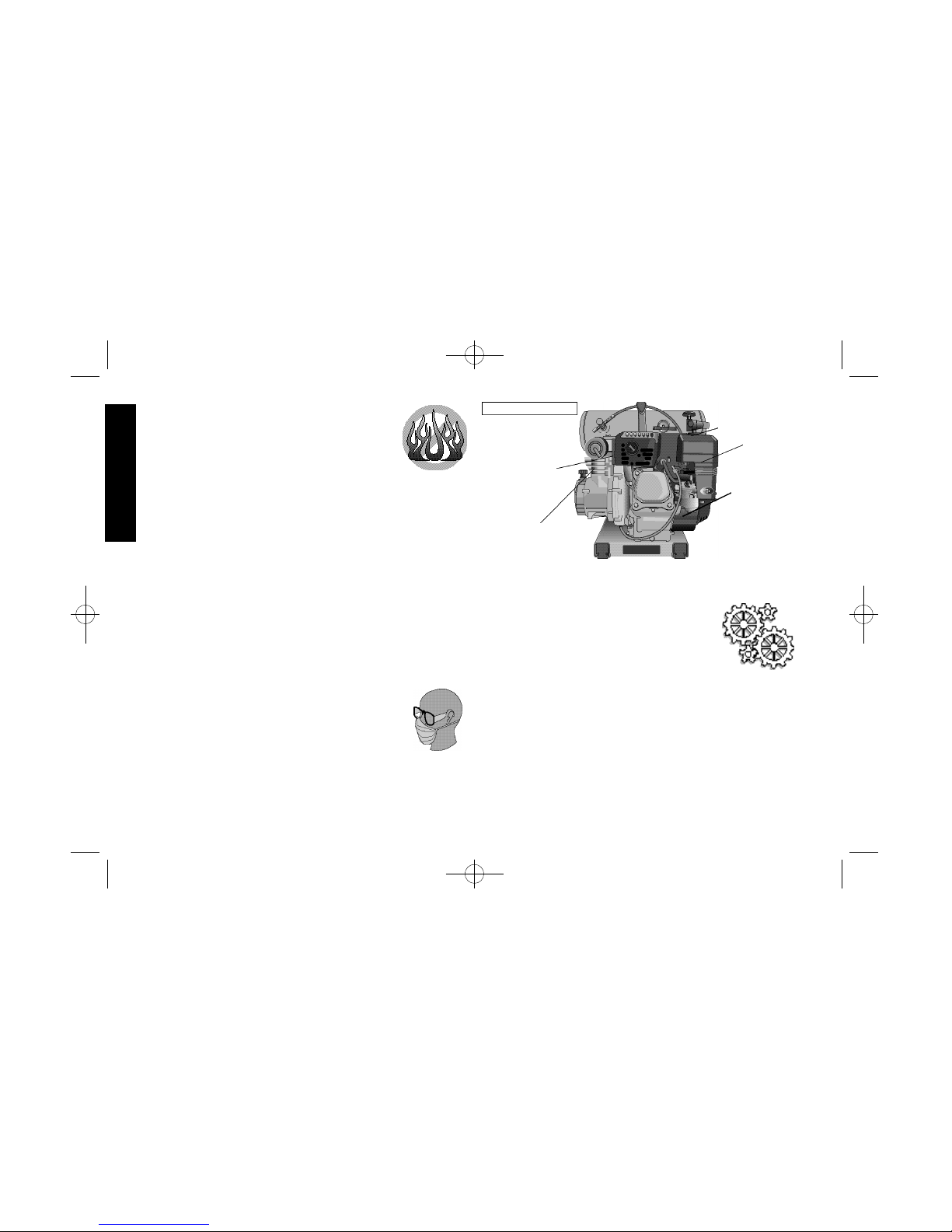
COMPRESSOR
CYLINDER
TRANSFER TUBE
(NOT SHOWN)
MUFFLER
COMPRESSOR
PUMP HEAD
HOT SURFACES
ENGINE
CYLINDER
5135176-00,01Gas Hand Carry 2/10/03 2:54 PM Page 2
Page 7
burns contributing to the dropping of the compressor, damaging the
compressor and/or injuring the operator.
ENGINE
Your air compressor is powered by a Honda®gasoline engine. Most
accidents with engines can be prevented if you follow all instructions
in this manual, the engine owner’s manual and on the engine. Some
of the most common hazards are discussed herein, along with the
best way to protect yourself and others:
• Know how to stop the engine quickly, and understand
the operation of all controls.
• Never permit anyone to operate the engine without proper
i n s t r u c t i o n s .
• Do not allow children to operate the engine.
• Keep children and pets away from the area of operation.
Refuel with care: ALLOW THE ENGINE TO COOL. Gasoline is
extremely flammable, and gasoline vapor can explode. Refuel outdoors, in a well-ventilated area, with the engine off. Never smoke
near gasoline, and keep flames and sparks away. Always store gasoline in an approved container. If any fuel is spilled, move compressor to another location before starting the engine.
Carbon Monoxide Hazards:Exhaust gas contains poisonous carbon monoxide. Avoid inhalation of exhaust gas. Never run the engine
in a closed garage or confined area.
Introduction
Congratulations on the purchase of your new DEWA LTAir Compressor! You can be assured that this tool has been constructed
with the highest level of precision and accuracy. Each component
has been rigorously tested by technicians to ensure the quality, endurance and performance of this air compressor.
By reading and following the safety, operation, maintenance, and
troubleshooting steps described in this manual, you will receive
years of trouble-free operation.The manufacturer reserves the right
to make changes in price, color, materials, equipment specifications,
or models at any time without notice.
Inspection of Compressor
Inspect for signs of obvious or concealed freight damage. Report any
damage to the delivering freight carrier immediately. Be sure that all
damaged parts are replaced and any mechanical problems are
corrected prior to the operation of the air compressor. The air compressor serial number is located on the shroud of the compressor.
Please write the serial number in the space provided in the service
section for future reference.
DEWALT Air Compressor Features
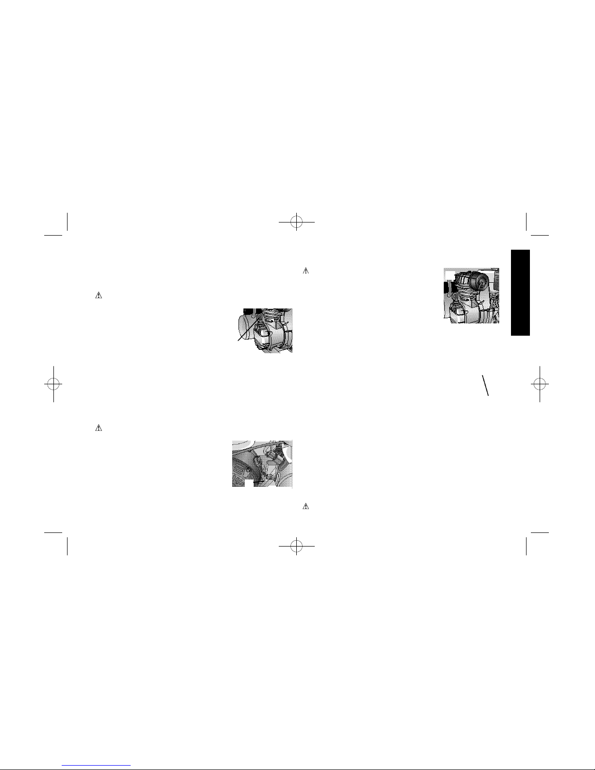
Pilot Valve
Pilot valves maintain a constant pressure range while running
c o n t i n u o u s l y. The pilot valve may be used to operate a discharge line
unloader or an unloading device in the
compressor head. The DEWA LT c o mpressor unloads through the compressor head. Unloading occurs when
the receivers (tanks) reach a preset cutout pressure limit. The pilot valve opens, actuating the unloading
device that allows the compressor to run in an unloaded mode.
When the tank pressure drops to the preset cut-in pressure, the pilot
valve closes allowing the unloading device to close and the compressor once again pumps air into the tanks.
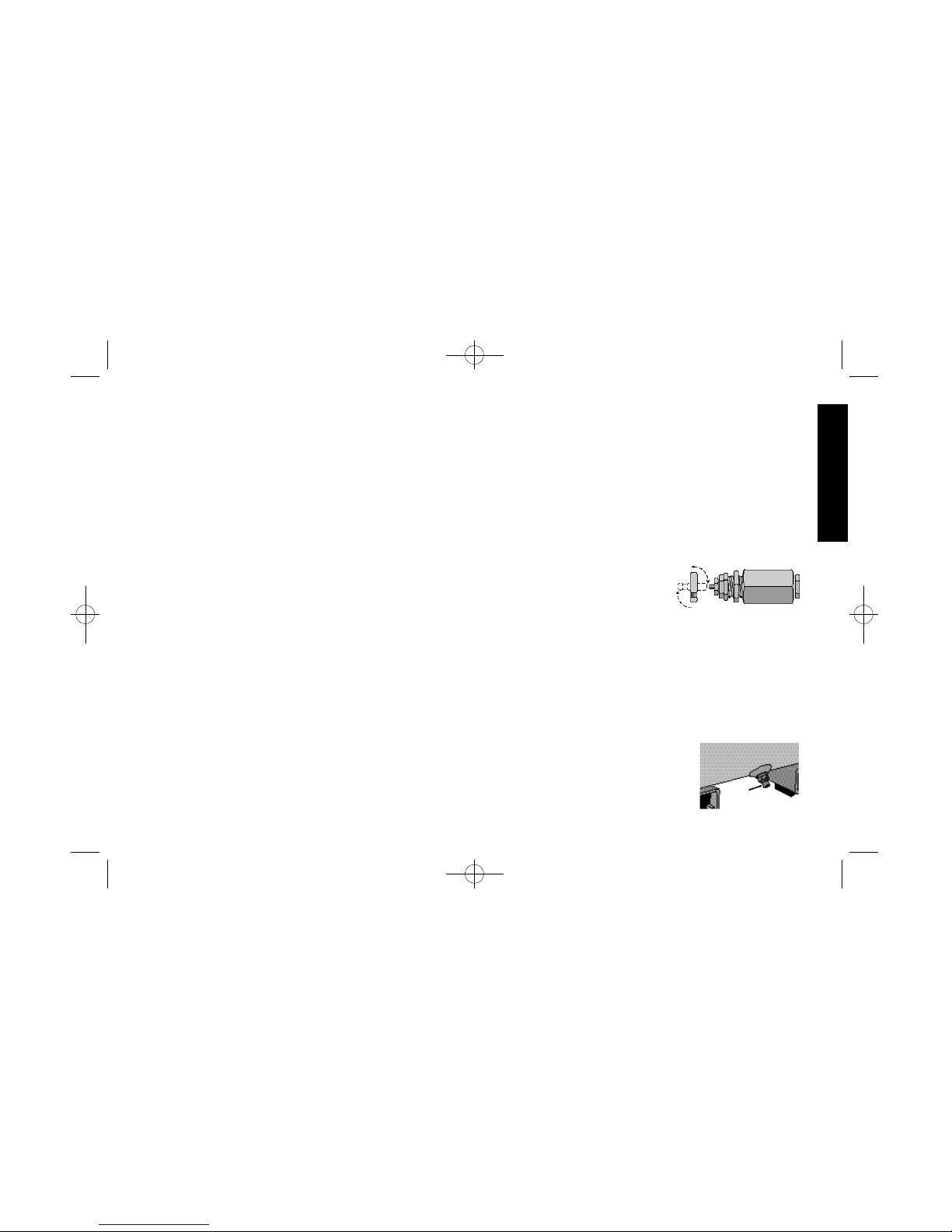
Manual Lock
The manual lock allows you to manually unload the compressor
with air pressure in the tank. To operate the unloading device in the
head, rotate the flip lever to an in-line position (dashed lines). Be sure
to return lever to the loaded position after
starting the engine or the pump will not operate
at preset pressures.
SAFETY RELIEF VALVE
This valve is designed to prevent system
failures by relieving pressure from the system
when the compressed air reaches a predetermined level. The valve is preset by the manufacturer and must not be
3
A
5135176-00,01Gas Hand Carry 2/10/03 2:54 PM Page 3
Page 8
WARNING : Do not loosen
screw (C) more than 1 revolution as
screw is subjected to tank pressure
and can burst out which can harm
the user or surrounding personnel.
2 . Turn screw (C) clockwise to
increase cut-out pressure limit or counter clockwise to decrease
cut-out pressure. For example: if the cut-out pressure limit on the
tank gage reads 120 PSI. and desired cut out is 130 PSI, turn
screw (C) clockwise.
3 . Drain air from tanks through the drain valves until the pump
begins to charge tanks.
4 . Close the drain valves.
5 . Monitor tank pressure gage to ensure the new cut-out pressure
limit setting.
6 . Once setting is complete hold screw (C) firmly and tighten nut (D).
PILOT VALVE PRESSURE DIFFERENTIALADJUSTMENT
N O T E : The compressor can run during this adjustment.
WARNING :A f t e r c o o l e r, pump head, and surrounding parts are
very hot. Do not touch (see Hot Surfaces on page 2).
WARNING - Moving Parts: Keep your hair, clothing and gloves
away from moving parts. Loose clothing, jewelry, or long hair can be
caught in moving parts. Air vents may cover moving parts and
should be avoided as well. Do not remove the protective covers from
this product.
1 . Hold (E) firmly and loosen nut (F).
WARNING : Do not loosen barrel (E) more than 1 revolution
because the barrel is subjected to tank pressure and can burst out
harming the user or surrounding persons.
2. Turn the barrel (E) clockwise to increase differential or counter
clockwise to decrease the differential. For example, if the pressure
d i fferential is 100 - 130 PSI and 100 - 120 PSI is desired, turn
(E) counter clockwise.
4
modified in any way.
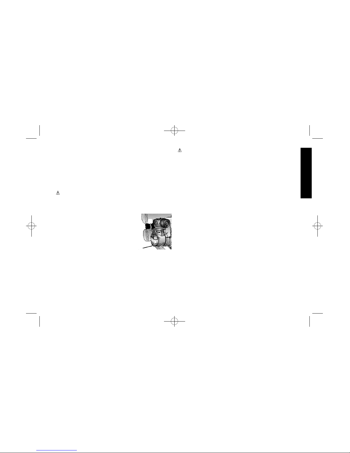
AIR TANK DRAIN VALVE
The drain valve (A) is used to remove
moisture from the air tank after the air
compressor is shut off .
AIR INTAKE FILTER
This filter (B) is designed to clean air entering the pump. To ensure that the pump
continually receives a clean, cool, and dry air supply, the filter must
always be clean and the filter intake must be free from obstructions.
TANK PRESSURE GAGE
The tank pressure gauge indicates air pressure in the air tank.
REGULATED PRESSURE GAGE
The regulated pressure gage indicates the air pressure available at
the outlet side of the regulator. This pressure is controlled by the
regulator and is always less than or equal to the air tank pressure.
PRESSURE REGULATOR
The regulator knob controls the air pressure coming from the air
t a n k .
Common Procedures
PILOT VALVE CUT-OUT PRESSURE ADJUSTMENT
N O T E : The compressor can run during this adjustment.
WARNING : A f t e r c o o l e r, pump head, and surrounding parts are
very hot. Do not touch (see Hot Surfaces on page 2).
WARNING - Moving Parts: Keep your hair, clothing and gloves
away from moving parts. Loose clothing, jewelry, or long hair can be
caught in moving parts. Air vents may cover moving parts and
should be avoided as well. Do not remove the protective covers from
this product.
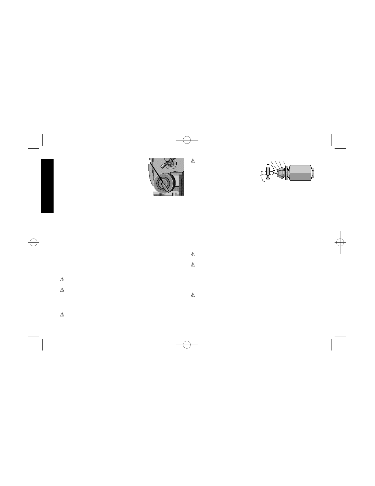
WARNING : The pilot valve is brass which is a soft metal. Do not
overtighten screw as threads can strip out.
1. Hold (E) firmly and loosen nut (D).
C
D E F
B
5135176-00,01Gas Hand Carry 2/10/03 2:54 PM Page 4
Page 9
move or is difficult to move.
CHECKING AIR FILTER ELEMENT
WA R N I N G : A f t e r c o o l e r, pump head, and
surrounding parts are very hot. Do not touch.
(see Hot Surfaces on page 2).
1 . Ensure that the compressor is not running
and the engine is off .
2. Allow the compressor to cool.
3 . Unscrew the filter from the pump head by
turning the filter counter clockwise.
4 . Separate the filter body into two halves.
5 . If the filter element needs cleaning blow it out with air. Replace
air filter assembly if unsure whether element can be cleaned
s u ff i c i e n t l y.
6 . Reconnect the halves of the filter body.
7 . Screw the filter into the pump head by turning clockwise until the
filter is hand tight.
STARTING UNIT
Follow the pre-start and start-up procedures in the operating
procedures section.
TURNING UNIT OFF
Follow the Stopping the Engine procedures in engine owner’s
m a n u a l .
ADJUSTING REGULATOR
1 . Pull regulator knob out.
2 . Turn knob clockwise to increase regulated pressure and counter
clockwise to decrease regulated pressure.
3 . When desired pressure is shown on the regulated pressure gage
push knob in to lock.
INSTALLING HOSES
WARNING: Firmly grasp the hose when installing or disconnect -
ing to prevent hose whip.
NOTE :Too narrow a differential can cause chatter of the pilot valve.
Increase the differential to eliminate chatter.
3 . Hold barrel (E).
4 . Hold (E) firmly and tighten nut (F).
CHECKING THE COMPRESSOR PUMP OIL LEVEL
WA R N I N G : A f t e r c o o l e r, pump head, and surrounding parts are
very hot. Do not touch (see Hot Surfaces on page 2).
1 , Ensure that the compressor is not running
and the engine is off .
2 . Place the compressor on a level horizontal
s u r f a c e .
3 . Remove dipstick (G) from oil fill port.
4 . Look for contaminants (water, dirt, etc.) in
the oil on dipstick.
5 . Wipe oil off of the dipstick.
6 . Reinsert dipstick fully into oil fill port for a few seconds to allow oil
to collect on the dipstick.
7 . Remove oil dipstick to read oil level. Oil should not exceed top
raised line on dipstick. If oil is below lower mark, add DEWA LT
synthetic oil and follow steps 5 - 7.
CHECKING SAFETY RELIEF VALVE OPERATION
WA R N I N G :A f t e r c o o l e r, pump head, and surrounding parts are
very hot. Do not touch (see the Hot Surfaces
identified on page 2).
1 . Ensure that the compressor is not running
and the engine is off .
2 . Ensure that the tank is empty by looking at
tank pressure gage. Drain the tanks if ne-
c e s s a r y.
3 . Grasp the wire ring on safety valve (H).
4 . Pull and release the ring a few times to ensure that the plunger
moves in and out. Replace the safety valve if the plunger does not
5
H
G
I
5135176-00,01Gas Hand Carry 2/10/03 2:54 PM Page 5
Page 10

6
4 . Grasp the knurled drain knob.
5 . Slowly rotate the knob counterclockwise to gradually bleed air
from tank.
6 . When the tank is at 10 psi, rotate valve to the fully open position.
7 . Close the drain valve when finished.
Preparation For Use
INITIAL SET-UP
Read safety instructions before setting-up the air compressor.
1 . Remove the oil plug.
2 . Pour DEWA LTsynthetic oil into crankcase (4 oz.).
WA R N I N G : THE COMPRESSOR IS SHIPPED WITHOUT OIL IN THE
CRANKCASE. ADD OIL.
3 . Insert the dipstick.
4 . Close the tank drain valve.
C A U T I O N : Do not operate without lubricant or with inadequate
lubricant. DEWA LT is not responsible for compressor failure caused
by inadequate lubrication.
Compatibility
Air tools and accessories that are operated with the compressor
must be compatible with petroleum based products. If you suspect
that a material is not compatible with petroleum products, use an air
line filter for removal of moisture and oil vapor in compressed air.
NOTE: Always use an air line filter to remove moisture and oil vapor
when spraying paint.
Location
C A U T I O N : In order to avoid damaging the air compressor, do not
allow the unit to be tilted more than 10˚ when operating.
Place air compressor at least 3 feet away from obstacles that may
prevent proper ventilation. Keep unit away from areas that have dirt
and/or volatile fumes in the atmosphere. These impurities may clog
the intake filter and valves, causing inefficient operation.
1 . Ensure that the regulated pressure gage reads 0 PSI.
2 . Grasp the hose at coupler.
3 . Pull back the collar on female quick-connect coupler located on
the compressor.
4 . Push the male connector into the female connector.
5 . Release the female connector.
6 . Grasp the hose and pull to ensure that the couplers are seated.
7 . Adjust the regulator to the desired pressure.
DISCONNECTING HOSES
WARNING: Firmly grasp the hose when installing or disconnect -
ing to prevent hose whip.
1 . Ensure that the regulated pressure gage reads 0 PSI.
2 . Grasp the hose at the coupler.
3 . Pull back the collar on female quick-connect coupler located on
the compressor.
4 . Pull the male connector out of the female connector.
5 . Release the female connector.
DRAINING TANKS
WA R N I N G :Tanks contain high pressure air. Keep the drain outlet
away from face and other body parts. Use safety glasses when
draining the tank because debris can be propelled into face. Use
ear protection because air flow noise is loud when draining tanks.
N O T E : All compressed air systems generate condensate that
accumulates in any drain point (e.g. tanks, filter, aftercoolers, dryers).
This condensate contains lubricating oil and/or substances which
may be regulated and must be disposed of in accordance with local,
state, and federal laws and regulations.
1 . Ensure that the compressor is not running and the engine is off .
2 . Move the compressor into an inclined position so that the drain
valve(s) are at the lowest point This will assist in removing
moisture, dirt, etc. from the tanks.
3 . Place a suitable container under the drain to catch discharge.
5135176-00,01Gas Hand Carry 2/10/03 2:54 PM Page 6
Page 11

are certified safe for the compressor’s discharge pressure and
temperature. Use pipe thread sealant on all threads, and tighten
joints thoroughly to prevent air leaks. DO NOT USE PVC PLASTIC.
CONDENSATE DISCHARGE PIPING
To install a condensate discharge line, use piping at least one size
larger than the connection. Connect the piping so that it is secured
tightly and is routed to a suitable drain point. Use as short and direct
a pipe as possible. Condensate must be disposed of in accordance
with local, state, and federal laws and regulations.
N O T E : All compressed air systems generate condensate that
accumulates in any drain point (e.g. tanks, filter, aftercoolers, dryers).
This condensate contains lubricating oil and/or substances which
may be regulated and must be disposed of in accordance with local,
state, and federal laws, and regulations.
Operating Procedures
Pre-Start Checklist
1 . Ensure that the ON/OFF lever on the engine is in the OFF
p o s i t i o n .
2 . Ensure that the tanks are drained so that moisture, dirt, etc. can
be eliminated.
3 . Ensure that the tank pressure gage reads 0 PSI.
4 . Ensure that the safety and drain valves are functioning properly.
5 . Ensure that the drain valves are closed.
6 . Check the oil level in the pump.
7 . Check the oil level in engine crankcase.
8 . Ensure that all guards and covers are in place and securely
mounted. Ensure that all labels are legible. Do not use the
compressor until all these items have been verified.
START-UP
1 . Ensure that the ON/OFF lever on the engine is in the OFF
p o s i t i o n .
7
HUMID AREAS
In frequently humid areas moisture may form in the bare pump and
produce sludge in the lubricant, causing running parts to wear out
p r e m a t u r e l y. Excessive moisture is especially likely to occur if the
unit is located in an unheated area that is subject to large
temperature changes. Two signs of excessive humidity are external
condensation on the bare pump when it cools down and a “milky”
appearance in compressor lubricant. You may be able to prevent
moisture from forming in the bare pump by increasing ventilation or
operating for longer intervals.
NOISE CONSIDERATIONS
Consult local officials for information regarding acceptable noise
levels in your area. To reduce excessive noise, use vibration mounts
or silencers, relocate the unit or construct total enclosures or baff l e
walls. Contact a DEWA LT service center or call 1-800-4DEWA LTf o r
a s s i s t a n c e .
TRANSPORTING
When transporting the compressor in a vehicle, trailer, etc., ensure
that the tanks are drained and the unit is secured. Use care when
driving to avoid tipping the unit over in the vehicle. The compressor
or surrounding items can be damaged if the compressor is tipped.
MOVING
When moving the compressor into a position for use, grasp the handle grip and carry the compressor as close to your body as possible.
WARNING: Ensure proper footing and use caution when carrying
the compressor to avoid a loss of balance.
Air Inlet Filter
C A U T I O N : Do not operate without the air inlet filter
General Requirements
The piping, fittings, receiver tank, etc. must be certified safe for at
least the maximum working pressure of the unit. Use hard welded
or threaded steel or copper pipes, cast iron fittings and hoses that
5135176-00,01Gas Hand Carry 2/10/03 2:54 PM Page 7
Page 12

8
1 . Turn off the air compressor.
2 . Drain the air tanks.
3 . Allow the air compressor to cool down before starting service.
4. Disconnect the spark plug wire.
N O T E : All compressed air systems contain maintenance parts (e.g.
lubricating oil, filters, separators) which are periodically replaced.
These used parts may be, or may contain, substances that are
regulated and must be disposed of in accordance with local, state,
and federal laws and regulations.
N O T E : Take note of the positions and locations of parts during
disassembly to make reassembly easier. The assembly sequences
and parts illustrated may differ for your particular unit.
N O T E :Any service operations not included in this section should be
performed by authorized service personnel.
MAINTENANCE CHART 200 Hrs.
P r o c e d u r e D a y We e k M o n t h or Ye a r l y
Check pump oil level X
Oil leak inspection X
Drain condensation in air tank(s) X
Check for unusual noise/vibration X
Check for air leaks** X
Inspect air filter X
Clean exterior of compressor X
Check safety relief valve X
Change pump oil * X
Replace air filter X
Engine - Follow maintenance chart in
engine owner’s manual.
* The pump oil must be changed after the first 20 hours of operation.
T h e r e a f t e r, every 200 hours or once a year, whichever comes first. In
2 . Pull out and turn the regulator knob counterclockwise until it is
fully closed. Push the knob in to lock it. The regulated pressure
gage should read 0 PSI.
3 . Ensure that there is fuel in the fuel tank.
4 . Turn the ON/OFF lever on the engine to the ON position.
5 . Rotate the manual lock on the pilot valve into the in-line position
to assist with start up.
6 . Follow the “Starting the Engine” procedures in the engine’s owner
m a n u a l .
7 . Rotate the manual lock on the pilot valve into a perpendicular
position so that the pump can charge the tanks.
8 . Allow compressor to pump up to the cut-out pressure limit.
N O T E : If any unusual noise or vibration is noticed, stop the com-
pressor and refer to the troubleshooting section.
9 . Attach the hose and accessory.
1 0 . Adjust the regulator to the desired setting.
SHUT-DOWN
1 . Follow the “Stopping the Engine” procedures in engine owner’s
m a n u a l .
N O T E : When finished using compressor, follow steps 2 - 6 below.
2 . Turn the regulator knob counterclockwise until it is fully closed.
Ensure that the regulated pressure gage reads 0 PSI.
3 . Remove the hose and accessory.
4 . Drain the air tank(s). Ensure that the tank pressure gage reads 0
P S I .
5 . Allow the compressor to cool down.
6 . Wipe the air compressor clean and store in a safe, non-freezing
a r e a .
Maintenance
The following procedures must be followed when maintenance or
service is performed on the air compressor.
5135176-00,01Gas Hand Carry 2/10/03 2:54 PM Page 8
Page 13
harsh environments, maintenance must be performed on an acceler ated schedule.
** To check for air leaks apply a solution of soapy water around joints.
While compressor is pumping to pressure and after pressure cuts out
look for air bubbles.
COMPRESSOR PUMP OIL CHANGE
NOTE: Pump oil contains substances that are regulated and must be
disposed of in accordance with local, state and federal laws and
r e g u l a t i o n s .
WARNING :A f t e r c o o l e r, pump head, and surrounding parts are
very hot. Do not touch (see Hot Surfaces on page 2).
1 . Ensure that the ON/OFF lever on the engine is in the OFF
p o s i t i o n .
2 . Allow the compressor to cool.
3 . Place a suitable container under the drain
plug (J).
4 . Remove the oil dipstick (K) from crankcase.
5 . Remove the oil drain plug.
6 . Allow ample time for all the oil to drain out.
( Tilting the compressor towards the drain
plug will assist in draining.)
7 . Re-install the oil drain plug.
8 . Fill the pump with DEWA LT synthetic compressor oil (4 oz).
9 . Re-install oil dipstick.
Accessories
Recommended accessories for use with your tool are available for
purchase from your local dealer or authorized service center. If you
need assistance in locating any accessory for your tool, contact:
DEWALT Industrial Tool Co., 701 East Joppa Road, Baltimore,MD
21286 or call 1-800-4-DEWALT.
C A U T I O N : The use of any other accessory not recommended
for use with this tool could be hazardous.
Service Information
Please have the following information available for all service calls:
Model Number ___________________________
Serial Number ___________________________
Date and Place of Purchase ________________
Important
To assure product SAFETYand RELIABILITY, repairs, maintenance
and adjustment should be performed by authorized service centers
or other qualified service personnel, always using identical
replacement parts.
Full One Year Warranty
DEWA LT heavy duty industrial tools are warranted for one year from
date of purchase. We will repair, without charge, any defects due to
faulty materials or workmanship. For warranty repair information, call
1 - 8 0 0 - 4 - DEWA LT. This warranty does not apply to accessories or
damage caused where repairs have been made or attempted by
others. This warranty gives you specific legal rights and you may
have other rights which vary in certain states or provinces.
FREE WARNING LABELR E P L A C E M E N T: If your warning labels
become illegible or are missing, call 1-800-4-DEWA LT for a free
r e p l a c e m e n t .
SAVE THESE INSTRUCTIONS
FOR FUTURE USE
9
K
J
5135176-00,01Gas Hand Carry 2/10/03 2:54 PM Page 9
Page 14
10
Troubleshooting Guide
This section provides a list of the more frequently encountered malfunctions, their causes and corrective actions. The operator or
maintenance personnel can perform some corrective actions, and others may require the assistance of a qualified DEWA LT t e c h n i c i a n
or your dealer.
P r o b l e m C o d e
Compressor does not start or restart . . . . . . . . . . . . . . . . . . . . . . . . . . . . . . . . . . . . . . . . . . . . . . . . . . . . . . . . . . . . . . . . . . . . . . . . . . . . . . . . . . . . . . . . . . . . . .1 6 , 1 7 , 1 8 , 1 9 , 2 0 , 3 6
Unit does not or is slow to come up to speed . . . . . . . . . . . . . . . . . . . . . . . . . . . . . . . . . . . . . . . . . . . . . . . . . . . . . . . . . . . . . . . . . . . . . . . . . . . . . . . .3 , 8 , 11 , 1 2 , 1 4 , 1 5 , 2 0 , 2 1 , 2 2 , 2 4 , 2 5 , 3 1
Air compressor not making enough air. . . . . . . . . . . . . . . . . . . . . . . . . . . . . . . . . . . . . . . . . . . . . . . . . . . . . . . . . . . . . . . . . . . . . . . . . . . . . . . . . . . . . . . . . . . .1 , 3 , 7 , 8 , 9 , 1 0 , 11 , 2 1 , 2 4 , 2 5 , 2 8 , 2 9
I n s u fficient pressure at air tool or accessory . . . . . . . . . . . . . . . . . . . . . . . . . . . . . . . . . . . . . . . . . . . . . . . . . . . . . . . . . . . . . . . . . . . . . . . . . . . . . . . . . .1 , 3 , 7 , 8 , 9 , 1 0 , 11 , 2 1 , 2 4 , 2 5 , 2 7 , 2 8 , 2 9
High oil consumption. . . . . . . . . . . . . . . . . . . . . . . . . . . . . . . . . . . . . . . . . . . . . . . . . . . . . . . . . . . . . . . . . . . . . . . . . . . . . . . . . . . . . . . . . . . . . . . . . . . . . . . . . . . . . . . . . . . . . . . .2, 1 1 , 1 2 , 1 5 , 3 0 , 3 2
Unit runs excessively hot . . . . . . . . . . . . . . . . . . . . . . . . . . . . . . . . . . . . . . . . . . . . . . . . . . . . . . . . . . . . . . . . . . . . . . . . . . . . . . . . . . . . . . . . . . . . . . . . . . . . . . . . . . . . . . . .1 , 2 , 4 , 5 , 1 0 , 11 1 3 , 1 5 , 1 9 , 3 0
Excessive starting and stopping. . . . . . . . . . . . . . . . . . . . . . . . . . . . . . . . . . . . . . . . . . . . . . . . . . . . . . . . . . . . . . . . . . . . . . . . . . . . . . . . . . . . . . . . . . . . . . . . . . . . . .7 , 2 0 , 2 1 , 2 4 , 2 5 , 2 9
Excessive noise during operation . . . . . . . . . . . . . . . . . . . . . . . . . . . . . . . . . . . . . . . . . . . . . . . . . . . . . . . . . . . . . . . . . . . . . . . . . . . . . . . . . . . . . . . . . . . . . . . . . .2 , 3 , 4 , 5 , 8 , 9 , 1 0 , 11 0 , 3 1
Moisture in discharge air. . . . . . . . . . . . . . . . . . . . . . . . . . . . . . . . . . . . . . . . . . . . . . . . . . . . . . . . . . . . . . . . . . . . . . . . . . . . . . . . . . . . . . . . . . . . . . . . . . . . . . . . . . . . . . . . . .3 4 , 3 5
Moisture in crankcase or "milky" appearance in petroleum lubricant or rusting in cylinders. . . . . . . . . .6 , 7 , 9 , 1 0 , 1 5 , 2 5 , 2 6 , 3 3 , 3 5
Oil in discharge air (oil pumping) . . . . . . . . . . . . . . . . . . . . . . . . . . . . . . . . . . . . . . . . . . . . . . . . . . . . . . . . . . . . . . . . . . . . . . . . . . . . . . . . . . . . . . . . . . . . . . . . . . . .2 , 6 , 8 , 9 , 1 0 , 11 , 1 5 , 3 1 , 3 2
Oil leaking from shaft seal. . . . . . . . . . . . . . . . . . . . . . . . . . . . . . . . . . . . . . . . . . . . . . . . . . . . . . . . . . . . . . . . . . . . . . . . . . . . . . . . . . . . . . . . . . . . . . . . . . . . . . . . . . . . . . . .1 2
Safety relief valve "pops" . . . . . . . . . . . . . . . . . . . . . . . . . . . . . . . . . . . . . . . . . . . . . . . . . . . . . . . . . . . . . . . . . . . . . . . . . . . . . . . . . . . . . . . . . . . . . . . . . . . . . . . . . . . . . . . .2 2 , 2 3
Air leaks at pump . . . . . . . . . . . . . . . . . . . . . . . . . . . . . . . . . . . . . . . . . . . . . . . . . . . . . . . . . . . . . . . . . . . . . . . . . . . . . . . . . . . . . . . . . . . . . . . . . . . . . . . . . . . . . . . . . . . . . . . . . . . .25
Air leaks at fittings. . . . . . . . . . . . . . . . . . . . . . . . . . . . . . . . . . . . . . . . . . . . . . . . . . . . . . . . . . . . . . . . . . . . . . . . . . . . . . . . . . . . . . . . . . . . . . . . . . . . . . . . . . . . . . . . . . . . . . . . . . . .2 5
Air leaks from tank . . . . . . . . . . . . . . . . . . . . . . . . . . . . . . . . . . . . . . . . . . . . . . . . . . . . . . . . . . . . . . . . . . . . . . . . . . . . . . . . . . . . . . . . . . . . . . . . . . . . . . . . . . . . . . . . . . . . . . . . . .2 6
Abnormal piston ring or cylinder wear . . . . . . . . . . . . . . . . . . . . . . . . . . . . . . . . . . . . . . . . . . . . . . . . . . . . . . . . . . . . . . . . . . . . . . . . . . . . . . . . . . . . . . . . . . . .2 , 4 , 5 , 6 , 9 , 1 0 , 11 , 1 3
5135176-00,01Gas Hand Carry 2/10/03 2:54 PM Page 10
Page 15
11
TROUBLESHOOTING CODES
C o d e Possible Cause Possible Solution
1 Clogged or dirty inlet and/or discharge line filter. Clean or replace air inlet or discharge line filter.
2 Lubricant viscosity too low. Drain existing lubricant and refill with DEWA LT Synthetic lubricant.
3 Air leaks in air discharge piping. Check tubing and connections.
4 Lubricant viscosity too high. Drain existing lubricant and refill with DEWA LT Synthetic lubricant.
5 Lubricant level too low. Add lubricant to crankcase to proper level. Check for bearing damage.
6 Detergent type lubricant being used. Drain existing lubricant and refill with DEWA LT Synthetic lubricant.
7 Extremely light duty cycles. Run unit for longer duty cycles.
8 Compressor pump check valve is loose, broken, Inspect valves. Clean or replace as required.
or has carbon buildup.
9 Carbon build up on top of compressor pump piston. Clean piston. Repair or replace as required.
1 0 Compressor pump piston rings damaged or worn Install new rings.
(broken, rough, or scratched).
Compressor pump piston rings show excessive end gap or
side clearance.
Compressor pump piston rings not seated, stuck in grooves
or end gaps are not staggered.
11 Compressor cylinder or piston scratched, worn, or scored. Repair or replace as required.
1 2 Compressor connecting rod, piston pin, Inspect all. Repair or replace as required
or crankpin bearings worn or scored.
1 3 Compressor crankshaft seal worn or crankshaft scored. Replace seal or crankshaft assembly.
1 4 Extremely dusty atmosphere. Install more effective filtration or relocate the compressor.
1 5 Ambient temperature too low. Relocate compressor to warmer environment. Ensure that DEWA LT
synthetic oil is in crankcase.
1 6 Worn compressor cylinder finish. Deglaze cylinder with 180 grit flex-hone.
1 7 Air compressor is not large enough for air required. Check accessory air requirement. If higher than the CFM or pressure
supply of air compressor, then larger air compressor is required.
5135176-00,01Gas Hand Carry 2/10/03 2:54 PM Page 11
Page 16

12
C o d e Probable Cause Probable Solution
1 8 Possible defective safety/relief valve. Operate safety relief valve manually by pulling on test ring. If it still
leaks, replace it.
1 9 Excessive air tank pressure. Adjust the pilot valve. If the problem still exists, replace pilot valve.
2 0 Defective gaskets. Replace and torque head bolts to 6 - 7 ft lbs.
2 1 Fittings not tight enough. Warning : Drain air before tightening. tighten fittings so air can not
be heard escaping. Check joint with soap solution. Do not
o v e r t i g h t e n
2 2 Defective or rusted air tank Air tank must be replaced. Do not attempt to repair air tank.
2 3 Pressure regulator knob not turned to high enough pressure Adjust pressure regulator knob to proper setting or replace.
or defective pressure regulator.
2 4 Hose or hose connections are to small or long. Replace with larger hose or connectors.
2 5 Possible defective (reed) valve. Remove pump head and inspect valve plate and (reed) valve.
Clear or replace valves as required.
2 6 Air compressor on uneven surface. Do not incline the air compressor more than 10˚ in any direction
while running.
2 7 Compressor crankcase overfilled with oil. Drain oil, Refill to proper level with DEWA LT synthetic oil.
2 8 Plugged oil dipstick vent. C l e a n .
2 9 Water in oil due to condensation. Drain oil. Refill to proper level with DEWA LT synthetic oil.
3 0 Condensation in air tank caused by high level of Drain air tank after every use. Drain air tank more often in humid
atmospheric humidity. weather and use an air line filter.
3 1 Compressor located in damp or humid location. Relocate the compressor.
3 2 Engine oil too low. Low oil shut off is on. Add engine oil.
3 3 Manual lock on pilot valve is in the loaded position. Move manual lock into an in-line position.
3 4 Engine idle speed too low. Increase idle speed.
3 5 Engine problem. See “Taking care of unexpected problems” in engine owners
m a n u a l .
5135176-00,01Gas Hand Carry 2/10/03 2:54 PM Page 12
Page 17

13
CARACTÉRISTIQUES
Poids: 30.84 kg. 68 lbs.
Hauteur: 431.8 mm 17.00 in.
Largeur: 457.20 mm 18.00 in.
Longueur: 546.10 mm 21.50 in.
Capacité en huile de la pompe : 4 oz
ENGINE
4 Hp Honda GX-120
Combustion interne, 4 courses
3450 tr / min
Capacité en huile : - .63 qt.
5135176-00,01Gas Hand Carry 2/10/03 2:54 PM Page 13
Page 18

SI VOUS AVEZ DES QUESTIONS OU VOUS VOULEZ NOUS
FAIRE PART DE VOS COMMENTAIRES CONCERNANT CET
O U T I L OU TOUT AUTRE OUTIL D E WA LT, COMPOSER SANS
FRAIS LE: 1 800 4 3 3-9 2 5 8 .
AV E RT I S S E M E N T !Lire et comprendre toutes les directives avant
d’utiliser cet outil, car le non-respect des directives suivantes pourrait
entraîner un choc électrique, un incendie ou des blessures graves.
CONSERVER CES DIRECTIVES
Consignes de sécurité
AV E RT I S S E M E N T : Une partie de la poussière créée par ce
produit contient des produits chimiques qui, dans l’État de la
Californie, sont reconnus comme étant susceptibles de causer le
c a n c e r, d’entraîner des malformations congénitales ou d’être nocifs
pour le système reproducteur. Parmi ces produits chimiques,
mentionnons notamment :
• les composés dans les engrais;
• les composés dans les insecticides, les herbicides et les pesticides;
• l’arsenic et le chrome dans le bois d’œuvre traité chimiquement.
Pour réduire le risque d’exposition à ces produits chimiques, porter
un équipement de sécurité approuvé, comme des masques
antipoussières, qui sont spécialement conçus pour filtrer les
particules microscopiques.
AV E RTISSEMENT : l’utilisation de ce produit augmente les
risques d’exposition à des produits chimiques qui, dans l’État de la
Californie, sont reconnus comme étant susceptibles de causer le
c a n c e r, d’entraîner des malformations congénitales ou d’être nocifs
pour le système reproductif. Éviter d’inhaler les vapeurs
environnantes. Se laver les mains après chaque utilisation.
AV E RT I S S E M E N T: Ce produit contient des produits chimiques, y
compris du plomb, qui, dans l’État de la Californie, sont reconnus
comme étant susceptibles de causer le cancer, d’entraîner des
malformations congénitales ou d’être nocifs pour le système
r e p r o d u c t e u r. Se laver les mains après la manipulation.
L’utilisateur de cet appareil doit comprendre toutes ces directives.
Toute personne qui utilise cet outil doit être sain d’esprit et faire
preuve d’intégrité physique totale et ne pas être sous l’influence
d’une substance susceptible de réduire son acuité visuelle ou sa
dextérité ou nuire à son jugement.
RÉSERVOIR D’AIR
Le réservoir dont est doté le compresseur d’air peut porter le code
UM (dans le cas d’appareils munis de réservoirs
supérieurs à 15,2 cm ou 6 pouces de diamètre) et il
est conçu conformément à la Section VIII, Div. 1 de
l’ASME. Tous les appareils sous pression doivent être
inspectés tous les deux ans. Pour trouver l’inspecteur
des appareils sous pression de votre région,
consulter la section appropriée des organismes
gouvernementaux de l’annuaire téléphonique ou composer le
1 8 0 0 433-9258 pour obtenir de l’aide.
Les conditions indiquées ci-après peuvent affaiblir le réservoir et
entraîner une violente explosion à l’intérieur de celui-c i:
1 . Le fait de ne pas purger convenablement l’eau condensée du
r é s e r v o i r, entraînant la corrosion et l’amincissement des parois
en acier du réservoir.Purger le réservoir quotidiennement ou après
chaque utilisation. Si le réservoir présente une fuite, le remplacer
immédiatement par un nouveau réservoir ou un nouvel équipement
de compresseur.
2 . Modifications apportées au réservoir du compresseur ou
tentatives de réparation.
Ne jamais percer un trou dans le réservoir ou ses accessoires, y
effectuer des soudures ou y apporter quelque modification que ce
s o i t .
3 . Modifications apportées au pressostat, à la soupape de sûreté ou
à tout autre composant contrôlant la pression du réservoir. Le
réservoir est conçu pour résister à des pressions d’utilisation
14
5135176-00,01Gas Hand Carry 2/10/03 2:54 PM Page 14
Page 19

précises. Ne jamais effectuer de réglages ou remplacer des pièces
en vue de modifier les pressions d’utilisation réglées en usine.
ACCESSOIRES
Lorsque la pression nominale des outils pneumatiques, des pistolets
pulvérisateurs, des accessoires à commande
pneumatique, des pneus et autres produits
gonflables est excédée, ces composants pourraient
e x p l o s e r, ou se détacher et se projeter en l’air, et
entraîner des blessures graves. Respecter les
recommandations des fabricants d’équipement et
ne jamais excéder les pressions nominales
maximales permises des accessoires. Ne jamais utiliser le
compresseur pour gonfler de petits objets nécessitant une basse
pression comme des jouets d’enfant, des ballons de football et de
basket-ball, etc.
RISQUE D’EXPLOSION OU D’INCENDIE
Toujours faire fonctionner le compresseur dans un
endroit bien aéré, exempt de matériaux combustibles,
d’essence ou de vapeurs de solvants. Si des
étincelles électriques provenant du compresseur
entrent en contact avec des vapeurs inflammables,
c e l l e s-ci peuvent s’enflammer et entraîner un
incendie ou une explosion. Lorsqu’on pulvérise des matériaux
inflammables, installer le compresseur à au moins 6,10 m (20 pi) en
amont de la zone de pulvérisation; il pourrait s’avérer nécessaire
d’utiliser une section supplémentaire de boyau.
Entreposer les matériaux inflammables en un lieu sûr, loin du
c o m p r e s s e u r.
Toute obstruction des prises d’air de ventilation du compresseur
risque de provoquer une surchauffe importante et entraîner un
incendie. Ne jamais placer d’objets sur le dessus du compresseur ou
contre celui-ci. Faire fonctionner le compresseur dans une zone
dégagée, située à au moins 0,91 m (3 pi) d’un mur ou de tout
obstacle pouvant restreindre l’apport d’air frais aux prises d’air de
v e n t i l a t i o n .
RISQUES CAUSÉS PAR LES OBJETS PROJETÉS EN L’AIR
Le flux d’air comprimé peut endommager les tissus mous de la peau
exposée et peut projeter à haute vitesse des impuretés, des
fragments, des particules détachées et de petits objets pouvant
causer des blessures graves. Lorsqu’on utilise le compresseur,
toujours porter des lunettes de sécurité approuvées, conformes à la
norme ANSI Z28.1, et dotées d’écrans latéraux. Ne jamais diriger le
flux d’air vers des personnes ou vers des animaux. N’utiliser que les
s o u fflettes approuvées par la OSHA.
RISQUES CAUSÉS PAR LARESPIRATION DE L’AIR
COMPRIMÉ
Il est dangereux de respirer l’air comprimé sortant du compresseur!
Le flux d’air peut contenir du monoxyde de carbone,
des vapeurs toxiques ou des particules solides. Ne
jamais inhaler l’air comprimé du compresseur
directement ou au moyen d’un appareil respiratoire
raccordé au compresseur.
Les matériaux pulvérisés comme la peinture, les
solvants de peinture, les décapants, les insecticides,
les herbicides, etc. contiennent des vapeurs nocives et des poisons.
R E M A R Q U E : ne faire fonctionner le compresseur que dans un
endroit bien aéré. Lire et respecter les consignes de sécurité
indiquées sur l’étiquette ou les fiches signalétiques du produit
pulvérisé. Utiliser un appareil respiratoire approuvé par
N I O S H / M S H A et conçu pour une utilisation
p a r t i c u l i è r e .
RISQUES CAUSÉS PAR LES PIÈCES
MOBILES
Le compresseur est conçu pour être utilisé en
mode de fonctionnement continu. Toujours mettre
le compresseur hors tension et purger la
15
5135176-00,01Gas Hand Carry 2/10/03 2:54 PM Page 15
Page 20

pression du boyau d’air et du réservoir avant d’en effectuer l’entretien
ou d’y fixer des outils ou des accessoires.
Toujours garder les cheveux, les vêtements et les gants éloignés des
pièces mobiles; les vêtements amples, les bijoux ou les cheveux
long peuvent y rester coincés. On doit aussi éviter les évents qui
recouvrent les pièces mobiles, le cas échéant. Ne pas retirer les
couvercles de protection de cet appareil. Ne jamais faire fonctionner
le compresseur si les dispositifs ou les couvercles de protection
sont endommagés ou retirés. Ne jamais se tenir debout sur le
c o m p r e s s e u r.
SURFACES CHAUDES
Ne pas toucher au métal à découvert (comme la tête de
compresseur ou le refroidisseur complémentaire) afin d’éviter les
risques de brûlures graves. Ne jamais toucher les pièces de métal à
découvert du compresseur pendant ou immédiatement après son
fonctionnement. Le compresseur demeure chaud pendant plusieurs
minutes après son arrêt. Ne pas déplacer le compresseur lorsqu’il
est en marche. Les pièces chaudes du moteur peuvent causer des
brûlures à l’utilisateur, qui risque de l’endommager ou de se
blesser en l’échappant.
MOTEUR
Cet outil est entraîné par un moteur à essence Honda. On peut
prévenir la plupart des accidents causés par un moteur en suivant
toutes les directives du présent guide, du guide d’utilisation du
moteur ainsi que celles inscrites sur le moteur. Ces directives
expliquent quelques-uns des risques les plus courants et décrivent
les meilleures façons de se protéger et de protéger les autres :
• S’assurer de savoir comment arrêter le moteur rapidement et
bien comprendre le fonctionnement des commandes.
• Ne jamais permettre à qui que ce soit de mettre le moteur en
marche avant d’avoir compris toutes les directives.
• Ne jamais permettre à un enfant de démarrer le moteur.
• Tenir les enfants et les animaux domestiques éloignés de la
zone de travail.
Précautions à prendre lorsqu’on fait le plein : L A I S S E R
REFROIDIR LE MOTEUR. L’essence est une substance
extrêmement inflammable qui peut faire exploser les vapeurs
environnantes. Faire le plein à l’extérieur, dans un endroit bien aéré,
une fois le moteur arrêté. Ne jamais fumer à proximité de l’essence.
Éviter de créer des étincelles et des flammes. Toujours entreposer
l’essence dans un contenant approuvé. En cas de déversement,
déplacer le compresseur avant de démarrer le moteur.
Risques associés au monoxyde de carbone : les gaz
d’échappement contiennent du monoxyde de carbone toxique.
Éviter d’inhaler ces gaz. Ne jamais faire fonctionner le moteur dans
un garage fermé ou un espace clos.
Introduction
Nous vous félicitons d’avoir fait l’acquisition d’un compresseur d’air
DEWA LT! Nous tenons à vous assurer que cet appareil a été
construit selon le plus haut niveau d’exactitude et de précision.
Chaque composant a été rigoureusement mis à l’essai par des
techniciens en vue de garantir la qualité, l’endurance et le rendement
CYLINDRE DU
COMPRESSEUR
TUBE DE
TRANSFERT (NON
ILLUSTRÉ)
SILENCIEUX
TÊTE DE
POMPE DU
COMPRESSEUR
SURFACES CHAUDES
CYLINDRE
DU
MOTEUR
16
5135176-00,01Gas Hand Carry 2/10/03 2:54 PM Page 16
Page 21

17
de ce compresseur d’air.
La lecture des étapes simples décrites dans le présent guide et qui
traitent des consignes de sécurité, de l’installation, du
fonctionnement, de l’entretien et du dépannage de cet appareil,
garantit à son nouveau propriétaire de nombreuses années de
fonctionnement sans problème. Le fabricant se réserve le droit
d’apporter en tout temps, sans avis préalable, des changements au
prix, à la couleur, aux matériaux, aux caractéristiques de
l’équipement ou aux modèles.
Inspection du compresseur
Inspecter le compresseur afin de s’assurer qu’il n’y a aucun signe
évident ou dissimulé de dommages causés durant le transport; le
cas échéant, signaler immédiatement tout dommage au
t r a n s p o r t e u r. S’assurer que toutes les pièces endommagées sont
remplacées et que tous les problèmes mécaniques sont corrigés
avant de faire fonctionner le compresseur. Le numéro de série du
compresseur d’air est indiqué sur le couvercle de protection de ce
d e r n i e r. Écrire le numéro de série dans l’espace réservé à cette fin
dans la section « Information sur les services », pour toute
consultation ultérieure.
Caractéristiques du compresseur d’air
DEWALT
Vanne pilote :
Les vannes pilotes servent à maintenir une plage de pressions
constante lorsque l’outil est en mode de fonctionnement continu.
On peut utiliser ce dispositif pour
commander la soupape de
décompression de la conduite de
décharge ou celui situé sur la tête de
c o m p r e s s e u r. Le compresseur d’air
DEWA LT se décharge par la tête de compresseur lorsque les bâches
de récupération (réservoirs) atteignent la pression de
déclenchement réglée en usine. La vanne pilote s’ouvre et actionne
le dispositif de décompression, ce qui permet au compresseur de
fonctionner en mode de décompression. Lorsque la pression des
réservoirs descend jusqu’à la pression d’enclenchement réglée en
usine, la vanne pilote se ferme, ce qui permet au dispositif de
décompression de se fermer et au compresseur de pomper de
nouveau l’air dans les réservoirs.
Dispositif de blocage manuel
Le dispositif de blocage manuel permet de décharger le compresseur manuellement lorsqu’il y a une pression d’air dans le réservoir.
Pour faire fonctionner le dispositif de décompression de la tête,
tourner le levier à bascule jusqu’à une position en ligne (lignes
pointillées), en s’assurant de remettre le levier en position de
chargement après avoir mis le moteur en marche. Sinon, la pompe
ne fonctionnera pas aux pressions
p r é é t a b l i e s .
SOUPAPE DE SÛRETÉ
Cette soupape sert à empêcher les pannes
en libérant de la pression du système
lorsque l’air comprimé atteint un niveau de
pression préétabli. Elle est préréglée en
usine et ne doit pas être modifiée de
quelque manière que ce soit.
ROBINET DE PURGE DU RÉSERVOIR
D’AIR
Le robinet de purge (A) sert à éliminer
l’humidité du réservoir d’air après l’arrêt du
c o m p r e s s e u r.
FILTRE À AIR
Ce filtre (B) sert à purifier l’air qui entre dans
la pompe. Pour être sûr que la pompe reçoit un flux constant d’air pur,
frais et sec, toujours s’assurer que le filtre est propre et que l’entrée d’air
est exempte de toute obstruction.
A
B
5135176-00,01Gas Hand Carry 2/10/03 2:54 PM Page 17
Page 22

MANOMÈTRE DU RÉSERVOIR
Le manomètre indique la pression dans le réservoir d’air.
MANOMÈTRE RÉGULÉ
Le manomètre régulé indique la pression d’air à la sortie du
r é g u l a t e u r. Cette pression est contrôlée par le régulateur, et elle est
toujours inférieure ou égale à celle du réservoir d’air.
RÉGULATEUR DE PRESSION
Le bouton du régulateur contrôle la pression provenant du réservoir
d ’ a i r.
Procédures courantes
RÉGLAGE DE LA PRESSION DE DÉCLENCHEMENT DE LA
VANNE PILOTE
R E M A R Q U E : l’appareil peut demeurer en marche lorsqu’on
e ffectue ces réglages.
AV E RT I S S E M E N T : le refroidisseur complémentaire, la tête de
pompe et les pièces contiguës sont très chauds; ne pas y toucher.
(Consulter lessurfaces chaudes identifiées à la page 1 5 . )
AV E RT I S S E M E N T concernant les pièces mobiles : toujours
garder les cheveux, les vêtements et les gants éloignés des pièces
mobiles; les vêtements amples, les bijoux ou les cheveux longs
peuvent y rester coincés. On doit aussi éviter les évents qui
recouvrent les pièces mobiles, le cas échéant. Ne pas retirer les
couvercles de protection de cet appareil.
AV E RT I S S E M E N T: la vanne pilote est constituée de laiton, qui
est un alliage doux. Ne pas trop serrer la vis afin d’éviter de fausser
le pas de vis.
1 . Tenir fermement l’élément « E » et
desserrer l’écrou «D » .
AV E RT I S S E M E N T : ne pas
desserrer la vis «C » de plus d’un tour
puisqu’elle est soumise à la pression
du réservoir et pourrait éclater, causant des blessures à l’utilisateur
ou aux personnes qui se trouvent à proximité du compresseur.
2 . Tourner la vis «C » vers la droite pour augmenter la pression de
déclenchement réglée en usine, ou vers la gauche pour la réduire
(p.ex., si la pression de déclenchement est réglée à 120 lb/po2
et qu’on veut l’augmenter à 130 lb/po2, on doit tourner la vis «C »
vers la droite).
3 . Purger l’air des réservoirs par les robinets de purge jusqu’à ce
que la pompe commence à alimenter les réservoirs d’air.
4 . Fermer les robinets de purge.
5 . Surveiller le manomètre du réservoir afin de s’assurer que le
nouveau réglage est exact.
6 . Une fois le réglage établi, tenir fermement la vis « C » et serrer
l’écrou «D » .
RÉGLAGE DE LA PRESSION DIFFÉRENTIELLE DE LA
VANNE PILOTE
R E M A R Q U E : l’appareil peut demeurer en marche lorsqu’on
e ffectue ces réglages.
AV E RT I S S E M E N T : le refroidisseur complémentaire, la tête de
pompe et les pièces contiguës sont très chauds; ne pas y toucher.
(Consulter lessurfaces chaudes identifiées à la page 1 5 . )
AV E RT I S S E M E N T concernant les pièces mobiles : toujours
garder les cheveux, les vêtements et les gants éloignés des pièces
mobiles; les vêtements amples, les bijoux ou les cheveux longs
peuvent y rester coincés. On doit aussi éviter les évents qui
recouvrent les pièces mobiles, le cas échéant. Ne pas retirer les
couvercles de protection de cet appareil.
1 . Tenir fermement l’élément « E » et desserrer l’écrou « F» .
AV E RT I S S E M E N T : ne pas desserrer le tube allongé « E » de
plus d’un tour puisqu’il est soumis à la pression du réservoir et
pourrait éclater, causant des blessures à l’utilisateur ou aux
personnes qui se trouvent à proximité du compresseur.
C D E F
18
5135176-00,01Gas Hand Carry 2/10/03 2:54 PM Page 18
Page 23

2 . Tourner le tube allongé « E » vers la droite pour augmenter la
pression différentielle, ou vers la gauche pour la réduire (p.ex., si
la pression différentielle est réglée entre 100 et 130 lb/po2 et
qu’on veut obtenir une pression qui varie entre 100 et 120 lb/po2,
on doit tourner le tube allongé « E » vers la gauche).
R E M A R Q U E : un écart trop minime pourrait faire vibrer la vanne
pilote. Si tel est le cas, augmenter la pression différentielle pour
éliminer les vibrations.
3 . Tenir le tube allongé « E » .
4 . Tenir fermement l’élément « E » et serrer
l’écrou «F » .
VÉRIFICATION DU NIVEAU D’HUILE DE
LA POMPE DU COMPRESSEUR
AV E RT I S S E M E N T : le refroidisseur
complémentaire, la tête de pompe et les
pièces contiguës sont très chauds; ne pas y
t o u c h e r. (Consulter les surfaces chaudesidentifiées à la page 1 5 . )
1 . S’assurer que l’appareil est arrêté et que le moteur est fermé.
2 . Placer l’appareil sur une surface horizontale plane.
3 . Retirer la jauge (G) de l’orifice de remplissage d’huile.
4 . Vérifier la jauge afin de s’assurer qu’il n’y a aucune impureté (eau,
saletés, etc.) dans l’huile.
5 . Essuyer la jauge.
6 . Réinsérer complètement la jauge dans l’orifice de remplissage et
attendre quelques secondes pour permettre à l’huile d’adhérer à
la jauge.
7 . Retirer la jauge afin de vérifier le niveau d’huile. Ce niveau ne doit
pas dépasser la marque supérieure indiquée sur la jauge. S’il se
situe sous la marque inférieure, ajouter de l’huile synthétique
DEWA LT et répéter les étapesde 5 à 7 décrites ci-d e s s u s .
VÉRIFICATION DU FONCTIONNEMENT DE
LA SOUPAPE DE SÛRETÉ
AV E RT I S S E M E N T : le refroidisseur
complémentaire, la tête de pompe et les pièces
contiguës sont très chauds; ne pas y toucher.
(Consulter les surfaces chaudes identifiées à la
page 15.)
1 . S’assurer que l’appareil est arrêté et que le
moteur est fermé.
2 . Vérifier le manomètre du réservoir pour s’assurer que ce dernier
est vide. Purger le réservoir, le cas échéant.
3 . Saisir l’anneau métallique de la soupape de sûreté (H).
4 . Tirer sur l’anneau à quelques reprises pour s’assurer que le
piston se déplace. Remplacer la soupape de
sûreté si le piston ne se déplace pas ou s’il
se déplace diff i c i l e m e n t .
VÉRIFICATION DE L’ÉLÉMENT DU FILTRE
À AIR
AV E RT I S S E M E N T : le refroidisseur
complémentaire, la tête de pompe et les pièces
contiguës sont très chauds; ne pas y toucher.
(Consulter lessurfaces chaudes identifiées à la page 15.)
1 . S’assurer que l’appareil est arrêté et que le moteur est fermé.
2 . Laisser refroidir l’appareil.
3 . Dévisser le filtre en le tournant vers la gauche pour le retirer de
la tête de pompe.
4 . Séparer le corps du filtre en deux moitiés.
5 . Si l’élément doit être nettoyé, utiliser un jet d’air. En cas de doute,
remplacer l’ensemble du filtre s’il est impossible de nettoyer
l’élément à fond.
6 . Rassembler le corps du filtre.
G
H
I
19
5135176-00,01Gas Hand Carry 2/10/03 2:54 PM Page 19
Page 24

20
7 . Réinstaller le filtre sur la tête de pompe en le vissant à la main
vers la droite.
MISE EN MARCHE DE L’APPAREIL
Suivre les procédures de pré-démarrage et de démarrage décrites
dans la section «Mode d’emploi» du présent guide.
ARR T DE LÕAPPAREIL
Suivre les procédures d’arrêt du moteur du guide d’utilisation du
m o t e u r.
RÉGLAGE DU RÉGULATEUR
1 . Tirer sur le bouton du régulateur.
2 . Tourner le bouton vers la droite pour augmenter la pression
régulée, ou vers la gauche pour la diminuer.
3 . Lorsque la pression voulue est indiquée sur le manomètre régulé,
pousser le bouton pour le verrouiller.
INSTALLATION DU BOYAU
AV E RT I S S E M E N T: saisir fermement le boyau pour l’installer ou
le désaccoupler afin de prévenir les coups de fouet.
1. S’assurer que le manomètre régulé indique 0 lb/po2.
2. Saisir le boyau au niveau du raccord.
3. Tirer sur le collet du raccord rapide femelle situé sur le
c o m p r e s s e u r.
4. Pousser le raccord mâle dans le raccord femelle.
5. Libérer le raccord femelle.
6. Saisir le boyau et tirer sur ce dernier pour s’assurer que les
raccords sont bien fixés.
7. Régler le régulateur à la pression voulue.
DÉSACCOUPLEMENT DU BOYAU
AV E RT I S S E M E N T: saisir fermement le boyau pour l’installer ou
le désaccoupler afin de prévenir les coups de fouet.
1 . S’assurer que le manomètre régulé indique 0 lb/po2.
2 . Saisir le boyau au niveau du raccord.
3 . Tirer sur le collet du raccord rapide femelle situé sur le
c o m p r e s s e u r.
4 . Tirer sur le raccord mâle pour le désaccoupler du raccord femelle.
5 . Libérer le raccord femelle.
PURGE DES RÉSERVOIRS
AV E RT I S S E M E N T: le réservoir contient de l’air haute pression.
Garder l’orifice de purge éloigné du visage et du corps. Porter des
lunettes de protection pendant la purge puisque des débris risquent
d’atteindre le visage. Porter des protecteurs auditifs car le flux d’air
émet un sifflement strident pendant la purge.
R E M A R Q U E : tous les systèmes à air comprimé génèrent un
condensat qui s’accumule à un point de vidange (par exemple, un
r é s e r v o i r, un filtre, un refroidisseur complémentaire ou un sécheur).
Ce condensat peut contenir du lubrifiant ou des substances
contrôlées, ou encore les deux, et doit être éliminé conformément
aux lois et aux règlements locaux, provinciaux et fédéraux.
1. S’assurer que le compresseur est arrêté et que le
moteur est fermé.
2 . Incliner le compresseur jusqu’à ce que les robinets de purge se
trouvent à la position la plus basse pour faciliter l’élimination de
toute trace d’humidité, de saletés, etc. des réservoirs.
3 . Mettre un contenant approprié sous l’orifice de purge pour y
laisser s’écouler les débris.
4 . Saisir le bouton moleté.
5 . Tourner lentement le bouton vers la gauche pour purger
graduellement l’air du réservoir.
6 . Lorsque la pression du réservoir atteint 10 lb/po2, tourner le
robinet pour l’ouvrir complètement.
7 . Fermer le robinet de purge une fois terminé.
5135176-00,01Gas Hand Carry 2/10/03 2:54 PM Page 20
Page 25

Préparation avant utilisation
ÉTAPES INITIALES
Lire et comprendre toutes les consignes de sécurité avant d’installer
le compresseur.
1 . Retirer le bouchon d’huile.
2 . Verser 113,4 ml (4 oz) d’huile synthétique DEWA LTdans le carter.
AV E R T I S S E M E N T : LE CARTER DU COMPRESSEUR D’AIR
NE CONTIENT PAS D’HUILE AU MOMENT DE LA L I V R A I S O N ;
ON DOIT DONC EN A J O U T E R .
3 . Insérer la jauge d’huile.
4 . Fermer le robinet de purge du réservoir.
MISE EN GARDE: ne pas faire fonctionner le compresseur sans
lubrifiant ou avec un lubrifiant inadéquat. DEWA LT ne peut pas être
tenue responsable des défaillances de compresseur causées par
une lubrification inadéquate.
Compatibilité
Les outils pneumatiques et les accessoires qu’on utilise avec le
compresseur doivent être compatibles avec les produits à base de
pétrole. Si on soupçonne qu’un matériel n’est pas compatible avec
ces produits, éliminer l’humidité et les vapeurs d’huile de l’air
comprimé au moyen d’un séparateur d’eau.
R E M A R Q U E : toujours utiliser un séparateur d’eau pour éliminer
l’humidité et les vapeurs d’huile lorsqu’on vaporise de la peinture.
Emplacement
MISE EN GARDE : afin d’éviter d’endommager le compresseur
d ’ a i r, ne pas l’incliner à plus de 10o lorsqu’il fonctionne. Laisser un
espace d’au moins 0,91 m (3 pi) autour du compresseur pour
assurer une ventilation appropriée. Éloigner l’appareil des zones à
atmosphère chargée de saletés, de vapeur ou d’émanations qui
risquent d’obstruer le filtre et les soupapes d’admission d’air, ou de
s’y agglutiner, ce qui réduirait l’efficacité de fonctionnement.
ENVIRONNEMENTS HUMIDES
Dans les environnements souvent humides, l’humidité peut
s’accumuler dans la pompe à vide et se condenser dans le lubrifiant,
entraînant ainsi l’usure prématurée des pièces mobiles. Un excès
d’humidité risque de se produire dans l’appareil s’il est situé dans
un environnement non chauffé soumis à des variations thermiques
importantes. Il existe deux signes d’humidité excessive : une
condensation se forme à l’extérieur de la pompe à vide lorsqu’elle
refroidit, et le lubrifiant à base de pétrole prend une apparence
laiteuse. On peut empêcher la formation d’humidité dans la pompe à
vide en augmentant la ventilation ou en la faisant fonctionner plus
l o n g t e m p s .
CONDITIONS DE BRUIT
Consulter les organismes de réglementation locaux pour connaître
les niveaux de bruit permis dans votre région. Pour réduire le bruit
excessif, installer des supports antivibratoires ou des silencieux,
déplacer l’appareil ou encore, construire une enceinte close ou des
murs déflecteurs. Communiquer avec un centre de service DEWA LT
ou composer le 18 0 0 4 3 3-9258 pour obtenir de l’aide.
TRANSPORT
Lorsqu’on transporte le compresseur dans un véhicule quelconque,
y compris une semi-remorque, s’assurer que les réservoirs sont
purgés et que l’appareil est solidement ancré. Conduire prudemment
afin d’éviter de faire basculer l’appareil à l’intérieur du véhicule et
d’endommager ainsi ce dernier ou les pièces contiguës.
DÉPLACEMENTS
Lorsqu’on déplace le compresseur en vue de son utilisation, le saisir
fermement la poignée et le transporter en le maintenant aussi près
du corps que possible.
AV E RT I S S E M E N T : garder les pieds bien ancrés et faire preuve
d’une grande prudence lorsqu’on déplace le compresseur afin
d’éviter de perdre l’équilibre.
21
5135176-00,01Gas Hand Carry 2/10/03 2:54 PM Page 21
Page 26

Filtre à air
MISE EN GARDE : ne jamais faire fonctionner le compres seur sans filtre à air.
Exigences générales
Les conduites, les raccords, la bâche de récupération, etc. doivent
être approuvés, à tout le moins, pour une utilisation sans danger
pour la pression de service maximale de l’appareil. Utiliser des
conduites en acier ou en cuivre dur soudées ou filetées, des
raccords en fonte et des boyaux certifiés sans danger pour la
pression et la température de refoulement de l’appareil. Enrober tous
les filets d’un scellant prévu à cette fin et serrer les joints à fond afin
de prévenir les fuites d’air. NE PAS UTILISER DE PLASTIQUE
P V C .
CONDUITE DE VIDANGE DE CONDENSAT
Pour installer une conduite de vidange de condensat, utiliser une
conduite d’au moins un diamètre supérieur au raccord, aussi courte
et directe que possible, fixée solidement et raccordée à un point de
vidange approprié. On doit éliminer le condensat conformément
aux lois et règlements locaux, provinciaux et fédéraux.
R E M A R Q U E : tous les systèmes à air comprimé génèrent un
condensat qui s’accumule à un point de vidange (par exemple, un
r é s e r v o i r, un filtre, un refroidisseur complémentaire ou un sécheur).
Ce condensat peut contenir du lubrifiant ou des substances
contrôlées, ou encore les deux, et doit être éliminé conformément
aux lois et aux règlements locaux, provinciaux et fédéraux.
Mode d’emploi
LISTE DE VÉRIFICATION DE PRÉ-DÉMARRAGE
1 . S’assurer que le levier « O N / O F F » du moteur est réglé à la
position « O F F » .
2 . S’assurer que les réservoirs sont purgés afin d’éliminer toute
trace d’humidité, de saleté, etc.
3 . S’assurer que le manomètre du réservoir indique 0 lb/po2.
4 . S’assurer que la soupape de sûreté et le robinet de purge
fonctionnent correctement.
5 . S’assurer que les robinets de purge sont bien fermés.
6 . Vérifier le niveau d’huile dans la pompe.
7 . Vérifier le niveau d’huile dans le carter du moteur.
8 . S’assurer que les dispositifs et les couvercles de protection sont
présents et bien fixés, et que les étiquettes sont bien apposées et
lisibles. Ne pas utiliser le compresseur avant d’avoir vérifié tous
ces articles.
DÉMARRAGE
1 . S’assurer que le levier « O N / O F F » du moteur est réglé à la
position « O F F » .
2 . Tirer sur le bouton du régulateur et le tourner vers la gauche pour
le fermer complètement, puis le pousser pour le verrouiller.
S’assurer que le manomètre régulé indique 0 l b / p o 2 .
3 . S’assurer que le réservoir d’essence est plein.
4 . Régler le levier « O N / O F F » du moteur à la position «O N ».
5 . Tourner le dispositif de blocage manuel situé sur la vanne pilote
jusqu’à la position en ligne afin de faciliter le démarrage.
6 . Suivre les directives indiquées à la section « Démarrage du
m o t e u r » du guide d’utilisation du moteur.
7 . Tourner le dispositif de blocage manuel situé sur la vanne pilote
jusqu’à la position perpendiculaire afin de permettre à la pompe
d’alimenter les réservoirs.
8 . Laisser le compresseur atteindre la pression de déclenchement.
R E M A R Q U E : si on remarque un bruit ou une vibration inhabituels,
arrêter le compresseur et consulter la section de dépannage du
présent guide.
9 . Fixer le boyau et les accessoires.
1 0 . Régler le régulateur jusqu’à la position voulue.
22
5135176-00,01Gas Hand Carry 2/10/03 2:54 PM Page 22
Page 27

ARR T
1 . Suivre les directives indiquées à la section « Arrêt du moteur »
du guide d’utilisation du moteur.
R E M A R Q U E: si on n’utilise plus le compresseur, passer aux étapes
de 2 à 6 indiquées ci-d e s s o u s .
2 . Tourner le bouton du régulateur vers la gauche pour le fermer
complètement. S’assurer que le manomètre régulé indique 0
l b / p o 2 .
3 . Enlever le boyau et les accessoires.
4 . Purger les réservoirs d’air. S’assurer que le manomètre du
réservoir indique 0 lb/po2.
5 . Laisser refroidir le compresseur.
6 . Nettoyer le compresseur d’air à l’aide d’un chiffon et l’entreposer
dans une zone sécuritaire, à l’abri du gel.
Entretien
Suivre les procédures décrites ci-dessous lorsqu’on effectue les
opérations d’entretien ou de maintenance du compresseur d’air.
1 . Arrêter le compresseur d’air.
2 . Purger les réservoirs da i r.
3 . Laisser refroidir le compresseur d’air avant de commencer
l ’ e n t r e t i e n .
4 . Débrancher le fil de bougie.
R E M A R Q U E : les circuits d’air comprimé contiennent des pièces
d’entretien (p. ex. huile de lubrification, filtres, séparateurs) qui sont
remplacées périodiquement.
Ces pièces usagées peuvent être, ou peuvent contenir, des
substances qui sont contrôlées et qui doivent être mises au rebut
conformément aux lois et aux règlements locaux, provinciaux et
f é d é r a u x .
R E M A R Q U E : noter l’emplacement et la position des pièces
pendant le démontage pour faciliter le remontage. Les séquences
et les pièces de montage illustrées peuvent varier d’un appareil à
l ’ a u t r e .
R E M A R Q U E : toute opération d’entretien qui n’est pas comprise
dans cette section doit être effectuée par le personnel d’entretien
a u t o r i s é .
Programme de maintenance
E n t r e t i e n J o u r S e m . M o i s 200 hrs
Vérifier le niveau d'huile
de la pompe X
Vérifier les fuites d’huile X
Purger la condensation
dans les réservoirs d'air X
Vérifier les bruits et les
vibrations inhabituels X
Vérifier les fuites d'air* X
Vérifier la courroie X
Inspecter le filtre à air X
Nettoyer l’extérieur du
c o m p r e s s e u r X
Vérifier la soupape de sûreté X
Vérifier le réglage de la courroie X
Changer l'huile de la pompe** X
* On doit changer l’huile de la pompe après les 20 premières heures de
fonctionnement. Par la suite, effectuer le changement d’huile toutes
les 200 heures ou une fois par an, selon la première éventualité.
Dans des environnements difficiles, l’entretien doit être effectué
selon un horaire plus accéléré.
** Pour vérifier les fuites d’air, appliquer une solution d’eau savonneuse
autour des joints.
Alors que le compresseur atteint la pression de déclenchement
voulue, couper la pression et vérifier la présence de bulles d’air
autour des joints.
23
5135176-00,01Gas Hand Carry 2/10/03 2:54 PM Page 23
Page 28

24
Vidange d’huile de la pompe du
compresseur
R E M A R Q U E : l’huile de la pompe contient des substances qui sont
contrôlées et qui doivent être mises au rebut conformément aux lois
et aux règlements locaux, provinciaux et fédéraux.
AV E RT I S S E M E N T : le refroidisseur
complémentaire, la tête de pompe et les pièces
contiguës sont très chauds; ne pas y toucher.
(Consulter les surfaces chaudes identifiées à la
page 2.)
1 . S’assurer que le levier « O N / O F F » du
moteur est à la position « O F F » .
2 . Laisser refroidir l’appareil.
3 . Mettre un contenant approprié sous le
bouchon de vidange (J).
4 . Retirer la jauge d’huile (K) du carter.
5 . Enlever le bouchon de vidange d’huile.
6 . Laisser suffisamment de temps pour permettre à l’huile de
s’écouler (incliner le compresseur vers le bouchon de vidange
pour faciliter la vidange).
7 . Réinstaller le bouchon de vidange d’huile.
8 . Verser 113,4 ml (4 oz) d’huile de compresseur synthétique
DEWA LT dans la pompe.
9 . Réinstaller la jauge d’huile.
Accessoires
Les accessoires recommandés pour l’outil sont vendus chez les
dépositaires locaux ou dans les centres de service autorisés. Pour
obtenir plus d’information sur les accessoires, communiquer avec
DEWA LT Industrial Tool Co., 701 East Joppa Road, Baltimore, MD
21286, aux États-Unis, ou composer le 1 800 433-9258.
MISE EN GARDE : l’usage d’un accessoire non recommandé
peut présenter un danger.
Information sur les services
Il est important d’avoir en main les renseignements suivants lors d’un
appel de service:
Numéro de modèle: ___________________________
Numéro de série_ _ _ _ _ _ _ _ _ _ _ _ _ _ _ _ _ _ _ _ _ _ _ _ _ _ _
Date et lieu de l’achat : _ _ _ _ _ _ _ _ _ _ _ _ _ _ _ _
Important
Pour assurer la SÉCURITÉ et la FIABILITÉ de cet outil, toutes les
opérations de réparation, d’entretien et de réglage doivent être
e ffectuées dans un centre de service autorisé ou par du personnel
qualifié; on ne doit utiliser que des pièces de rechange identiques.
Garantie complète d’un an
DEWA LT garantit les outils industriels de service intensif contre tout
défaut de matériel ou de fabrication pour une période d’un an à
compter de la date d’achat; le produit défectueux sera réparé sans
frais. Pour obtenir de plus amples renseignements sur les
réparations couvertes par la présente garantie, composer le
1 8 0 04 3 3-9258. Cette garantie ne s’applique pas aux accessoires et
ne vise pas les dommages causés par des réparations eff e c t u é e s
par un tiers. Cette garantie confère des droits légaux particuliers à
l ’ a c h e t e u r, mais celui-ci pourrait aussi bénéficier d’autres droits
variant d’un territoire à l’autre.
REMPLACEMENT GRATUIT DE L’ÉTIQUETTE D’AV E R T I SS E M E N T : en cas de perte ou d’endommagement des étiquettes
d’avertissement, composer le 1 8 0 0 4 3 3-9258 afin d’en obtenir de
nouvelles sans frais.
K
J
5135176-00,01Gas Hand Carry 2/10/03 2:54 PM Page 24
Page 29

25
Guide de Dépannage
Cette section fournit une liste des défauts de fonctionnement les plus fréquents, leurs causes et les mesures correctives. L'opérateur ou le
personnel de maintenance peut effectuer certaines mesures correctives, et d'autres peuvent nécessiter l'aide d'un technicien DEWA LT q u a l i f i é
ou d'un détaillant local.
Problème Code de problème
Usure anormale de la bague de piston ou du cylindre....................................................................2,5,6,11,12,14
L’appareil n'atteint pas son régime..................................................................................................4,8,15,20,21,38
L’appareil atteint lentement son régime ..........................................................................................3,4,8,15,17,20,21,25,26,30
L’appareil en marche est très chaud ..............................................................................................1,2,5,9,14,20,21,22
Bruit excessif durant le fonctionnement ........................................................................................3,4,5,8,9,10,11,12,16,26,30,31,38
Démarrage et arrêt excessif............................................................................................................3,8,21,22,25,26,30,35,38
Consommation d'huile élevée ........................................................................................................1,4,6,10,11,12,13,16,30,32,33,38
Cognement ou cliquetis ..................................................................................................................2,5,6,9,10,11,12,16,30,31,38
Humidité dans le carter, lubrifiant de pétrole d'apparence « laiteuse » ou
rouille dans les cylindres ................................................................................................................6,7,10,11,12,16,25,26,30,34,36,38
Huile dans l'air de décharge (pompage d'huile) ............................................................................2,6,8,10,11,16,32
Fuite d'huile du joint d'arbre ............................................................................................................13
La soupape de sûreté a bondi ........................................................................................................23,24
Le compresseur ne fonctionne ou ne redémarre pas......................................................................17,18,19,20,21
Fuites d'air au niveau de la pompe ................................................................................................25
Fuites d'air au niveau des raccords ................................................................................................26
Fuites d'air provenant du réservoir..................................................................................................27
Pression insuffisante de l'outil pneumatique ou de l'accessoire......................................................1,3,26,28,29
Le compresseur d’air ne fournit pas assez d’air..............................................................................1,3,4,8,10,11
Présence d’humidité dans l'air de décharge ..................................................................................35,36
Le moteur ne démarre pas. L’unité émet un ronflement et le disjoncteur se déclenche................37
5135176-00,01Gas Hand Carry 2/10/03 2:54 PM Page 25
Page 30

26
Code Cause possible Solution possible
1 Entrée et/ou filtre de ligne de décharge bloqué ou sale Nettoyer ou remplacer.
2 Viscosité du lubrifiant trop faible Vidanger le lubrifiant existant et remplir à l'aide du lubrifiant synthétique
DEWALT.
3 Viscosité du lubrifiant trop haute Vidanger le lubrifiant existant et remplir à l'aide du lubrifiant synthétique
DEWALT.
4 Niveau de lubrifiant trop bas Ajouter du lubrifiant au carter pour atteindre le niveau approprié. Vérifier si
les paliers sont endommagés.
5 Un lubrifiant de type détergent est utilisé. Vidanger le lubrifiant existant et remplir à l'aide du lubrifiant synthétique
DEWALT.
6 Cycles d'utilisation très courts Faire fonctionner l'unité pendant des cycles d'utilisation plus longs.
7 Clapet de non-retour du compresseur non étanche, brisé, carbonisé Nettoyer ou remplacer au besoin. Vérifier les clapets.
ou desserré
8 Accumulation de carbone sur le piston Nettoyer le piston. Réparer ou remplacer au besoin.
9 Segments de piston endommagés ou usés (brisés, irréguliers ou Installer de nouveaux segments.
égratignés). Entrefer d'extrémité ou dégagement latéral excessif.
Segments de piston non fixés, coincés dans les rainures ou entrefers
d'extrémité non décalés.
10 Cylindre ou piston égratigné, usé ou entaillé Réparer ou remplacer au besoin.
11 Bielle, axe de piston ou flasques à manetons usés ou entaillés Vérifier chaque pièce. Réparer ou remplacer au besoin.
12 Joint d'étanchéité de vilebrequin ou vilebrequin entaillé Remplacer le joint ou le vilebrequin.
13 Atmosphère extrêmement poussiéreuse Installer une filtration plus efficace ou relocaliser l'unité.
14 Température ambiante trop basse Relocaliser l'unité dans un environnement plus chaud. S'assurer que le
carter contient de l'huile synthétique DEWALT.
15 Finition du cylindre usée Sabler le cylindre à l'aide d'une lime flexible de 180 grains.
16 Cordon d'alimentation non branché Brancher le cordon sur la prise de mise à la terre.
17 Le bouton de protection contre les surcharges thermiques du moteur Arrêter le compresseur d'air, attendre que le moteur refroidisse,
est déclenché. puis appuyer fermement sur le bouton de protection contre les surcharges
thermiques du moteur (situé sur le moteur) jusqu'à ce qu'un déclic soit
entendu.
18 Fusible fondu ou circuit déclenché Remplacer le fusible ou réenclencher le disjoncteur. Vérifier le fusible
approprié; seuls les fusibles de type T« Fusetron » sont acceptés. Vérifier
si la tension est basse. Débrancher les autres appareils électriques du
ou faire fonctionner le compresseur d'air sur son circuit de dérivation.
5135176-00,01Gas Hand Carry 2/10/03 2:54 PM Page 26
Page 31

27
Code Cause possible Solution possible
19 Diamètre ou longueur du cordon de rallonge inapproprié Vérifier le guide à la page 4 pour obtenir le diamètre et la longueur de
cordon approprié.
20 Moteur, condensateur de moteur ou pressostat défectueux Communiquer avec le service à la clientèle DEWA LT au 1 800 4-DEWA LT.
21 Le compresseur d'air n'est pas assez grand pour la quantité d'air requise. Vérifier les exigences en matière d'aération des accessoires. Si elles sont
plus élevées que le ME ou la pression limite du compresseur d'air, un
compresseur d'air plus grand est nécessaire.
22 Soupape de sûreté possiblement défectueuse Faire fonctionner la soupape de sûreté manuellement en tirant sur
l'anneau d'essai. Si la soupape fuit toujours, la remplacer.
23 Pression excessive dans le réservoir d'air Régler le robinet pilote. Si le problème persiste, remplacer le robinet pilote.
24 Joints d'étanchéité défectueux Remplacer et serrer les boulons à tête au couple de 6 à 7 lb.pi.
25 Raccords desserrés Avertissement : Purger l’air avant de serrer les raccords. Serrer ces
derniers à l'endroit où l'échappement d'air n'est pas audible. Vérifier le
raccord à l'aide d'une solution savonneuse. Ne pas trop serrer.
26 Réservoir d'air défectueux ou rouillé Remplacer le réservoir d'air. Ne pas essayer de le réparer.
27 Le bouton du régulateur de pression n'est pas réglé à une pression Régler le bouton du régulateur de pression à la position appropriée
suffisamment élevée ou le régulateur de pression est défectueux. ou le
remplacer.
28 Le boyau ou les raccords à boyaux sont trop petits ou trop longs. Remplacer par un boyau ou des raccords de plus grandes dimensions.
29 Soupape flexible possiblement défectueuse Enlever la tête de la pompe et vérifier la plaque de la soupape et la
soupape flexible. Nettoyer ou remplacer les soupapes au besoin.
30 Le compresseur d'air se trouve sur une surface inégale. Ne pas incliner le compresseur d'air de plus de 10° dans un sens pendant
qu'il est en marche.
31 Carter trop rempli d'huile Vidanger l'huile. Remplir avec de l'huile synthétique DEWALT au niveau
approprié.
32 Évent de jauge d'huile obturé Nettoyer l’évent.
33 Présence d'eau dans l'huile en raison de la condensation Vidanger l'huile. Remplir avec de l'huile synthétique DEWALT au niveau
approprié.
34 Condensation dans le réservoir d'air en raison d'un niveau élevé Purger le réservoir d'air après chaque utilisation.
d'humidité atmosphérique Purger le réservoir d'air plus souvent en température humide et utiliser un
filtre de ligne d'air.
35 Unité située dans un endroit humide Relocaliser l'unité.
36 Pression dans les réservoirs d’air Purger complètement les réservoirs.
37 Soupape flexible possiblement défectueuse Enlever la tête de la pompe et vérifier la plaque de la soupape et la
soupape flexible. Nettoyer ou remplacer les soupapes au besoin.
5135176-00,01Gas Hand Carry 2/10/03 2:54 PM Page 27
Page 32

28
MOTOR
Honda 4 HP
Combustión interna 4 tiempos
3450 RPM
Capacidad de aceite del motor - 596 ml
ESPECIFICACIONES
Peso: 56 lbs. 25.40 kg.
Altura: 16.75 in. 425.45 mm
Ancho: 18.00 in. 457.20 mm
Peso 15.00 in. 381.00 mm
Capacidad de la bomba de aceite:
118 ml (4 oz.)
5135176-00,01Gas Hand Carry 2/10/03 2:54 PM Page 28
Page 33

29
SI TIENE CUALQUIER PREGUNTA O COMENTARIO A C E R C A
DE ESTA O DE CUALQUIER HERRAMIENTA D e WA LT, POR
FAVOR LL¡MENOS AL 1-800-4-DEWALT (1-800-433-9258).
A D V E RT E N C I A ! Lea y comprenda todas las instrucciones
antes de operar este compresor.No seguir todas las instrucciones
enlistadas a continuación puede ocasionar choques elÈctricos,
incendios y (o) lesiones personales de gravedad.
CONSERVE ESTAS
INSTRUCCIONES
Instrucciones de seguridad
La operación o el mantenimiento incorrectos de este producto puede
ocasionar lesiones graves y daños a sus objetos.
A D V E RTENCIA: Algunos polvos generados por este producto
contienen sustancias químicas que, en el estado de California, se
consideran causantes de cáncer, defectos congénitos y otros daños
reproductivos. Ejemplos de estas sustancias son:
• compuestos en fertilizantes
• compuestos en insecticidas, herbicidas y pesticidas
• arsénico y cromo proveniente de leña tratada químicamente
Para reducir su exposición a estas sustancias, lleve equipo de
seguridad aprobado, tal como mascarillas antipolvo especialmente
diseñadas para filtrar partículas microscópicas.
A D V E RT E N C I A : el Uso de este producto lo expondrá a
sustancias químicas conocidas al Estado de California de causar el
c a n c e r, los defectos del nacimiento y otro daño reproductor. E v i t e
vapores que inhalan y el polvo, y manos de lavado después de
u s a r.
A D V E RTENCIA: Este producto contiene sustancias químicas,
entre ellas plomo, que en el estado de California se consideran
causantes de cáncer, defectos congénitos y otros daños
reproductivos. Lávese las manos después de manipularlo.
TANQUE DE AIRE
El tanque en su compresor de aire DEWA LT D55250
está diseñado de conformidad con la sección VIII, Div.
1 de las reglas de ASME. Todos los contenedores a
presión deben inspeccionarse cada dos años. Para
encontrar al inspector estatal de contenedores busque la División de
Trabajo e Industrias en la sección gubernamental del directorio
telefónico llame al 1-800-4DEWA LT.
Las siguientes condiciones pueden llevar a debilitar el tanque, y
ocasionar un explosión violenta.
1 . No drenar el agua que se condensa en el tanque ocasiona
corrosión y adelgazamiento del acero del tanque. Drene el
tanque a diario o después de cada uso. Si el tanque desarrolla
una fuga, reemplácelo de inmediato con un tanque nuevo o con
un juego para compresor.
2 . Modificaciones o reparaciones al tanque del compresor.
Nunca taladre, suelde ni haga ningún tipo de modificaciones al
tanque o a sus dispositivos.
3 . No modifique la válvula de seguridad, ni cualquier otro
componente diferente al control de presión del tanque. E l
tanque está diseñado para soportar presiones de operación
específicas. Nunca haga ajustes o sustituciones de partes para
alterar los ajustes de operación de fábrica.
A D V E RT E N C I A : El empleo de este producto lo expondrá a
productos químicos que en el estado de California se consideran
como causantes de cáncer, defectos congénitos y otros daños
reproductivos. Evite inhalar los vapores y lave sus manos después
de usarlo.
DISPOSITIVOS YACCESORIOS
Exceder la capacidad de presión de las
herramientas de aire, pistolas de rocío, accesorios
operados con aire, neumáticos y otros objetos
inflables puede ocasionar que estallen o salgan
5135176-00,01Gas Hand Carry 2/10/03 2:54 PM Page 29
Page 34

30
despedidos, causando lesiones graves. Para el esencial control de
la presión del aire, deberá instalar un regulador de presión y un
manómetro a la salida de aire de su compresor. Siga las
recomendaciones de los fabricantes del equipo y nunca exceda la
presión máxima permitida para los dispositivos. Nunca utilice el
compresor para inflar objetos pequeños de baja presión como
juguetes, balones, etc.
RIESGO DE EXPLOSIÓN O INCENDIO
Opere siempre el compresor en un área bien ventilada, libre de
materiales combustibles y vapores de solventes o
gasolina. Si las chispas del compresor hacen
contacto con los vapores flamables, pueden
encenderse, ocasionando un incendios o
explosiones. Si va a rociar materiales flamables,
coloque el compresor a una distancia de al menos
6 metros del área de rocío. Se puede requerir de un
tramo de manguera adicional.
Guarde los materiales flamables en lugar seguro alejados del
c o m p r e s o r.
Restringir la ventilación a las aberturas del compresor ocasionará
sobrecalentamiento y probablemente un incendio. Nunca coloque
objetos contra el compresor o sobre éste. Opere el compresor en
una área abierta a una distancia mínima de 30 cm de cualquier muro
u obstrucción que restrinja el flujo de aire fresco hacia las aberturas
de ventilación.
RIESGO POR OBJETOS VOLADORES
La corriente de aire comprimido puede causar daños a los tejidos
suaves de la piel expuesta y puede impulsar mugre, astillas,
partículas sueltas y pequeños objetos a gran velocidad,
ocasionando lesiones graves. Utilice siempre gafas aprobadas A N S I
Z28.1 con cubiertas laterales cuando emplee el compresor. Nunca
dirija la corriente de aire comprimido hacia personas o animales.
Utilice únicamente pistolas de aire aprobadas por OSHA.
RIESGO RESPIRATORIO
¡El aire comprimido de su compresor no es seguro
para respirarlo! La corriente de aire puede contener
monóxido de carbono, vapores tóxicos o partículas
sólidas. Nunca inhale aire del compresor,
directamente o a través de un dispositivo para respirar
que esté conectado al compresor.
Los materiales rociados como pinturas, solventes, removedores,
insecticidas, herbicidas, etc. contienen vapores dañinos y venenos.
N O TA : Únicamente opere el compresor de aire en áreas bien
ventiladas. Lea y siga las instrucciones que vienen en la etiqueta u
hojas informativas de los materiales que vaya a rociar. Utilice un
respirador aprobado NIOSH/MSHA d i s e ñ a d o
para usarse específicamente con su aplicación.
RIESGO DE PIEZAS MÓVILES
El compresor está diseñado para funcionar
continuamente. Apague siempre el compresor,
purgue la presión de la manguera y del tanque, y
CILINDRO DEL
COMPRESOR
TUBO DE
TRANSFERENCIA
(NO ILUSTRADO)
AMORTIGUADOR
DE RUIDO
CABEZA DE LA
BOMBADEL
COMPRESOR
SUPERFICIES CALIENTES
CILINDRO
DEL
MOTOR
5135176-00,01Gas Hand Carry 2/10/03 2:54 PM Page 30
Page 35

31
desconecte de la alimentación de corriente antes de efectuar
mantenimiento o de instalar herramientas y accesorios.
Conserve cabello, ropas y guantes alejados de las partes móviles.
Las prendas de vestir sueltas, las joyas y el cabello largo pueden
resultar atrapados en las piezas móviles. No retire las cubiertas
protectoras de este producto. Nunca opere el compresor si las
guardas o cubiertas protectoras están dañadas o fuera de su sitio.
Nunca se pare sobre el compresor.
SUPERFICIES CALIENTES
Tocar metal expuesto como la cabeza del compresor o el tubo de
salida puede resultar en quemaduras severas. Nunca toque ninguna
parte metálica expuesta del compresor durante o inmediatamente
después de la operación. El compresor permanecerá caliente
durante varios minutos después de la operación. No mueva el
compresor cuando esté en funcionamiento. Las piezas calientes
del motor pueden causar quemaduras que contribuyan a la caída del
c o m p r e s o r, daños a éste y (o) lesiones al operador.
MOTOR
Su compresor de aire funciona con un motor Honda® a gasolina.
La mayoría de los accidentes con motores pueden evitarse si sigue
todas las instrucciones de este manual, el manual del propietario del
motor y las que están en el motor. Algunos de los peligros más
comunes se discuten aquí, junto con la manera de protegerlo a
usted y a terceras personas.
• Entérese de cómo apagar el motor rápidamente y entienda la
operación de todos los controles.
• Nunca permita que nadie opere el motor sin las instrucciones
a p r o p i a d a s .
• No permita que niños operen el motor.
• Conserve a los niños y mascotas lejos del área de operación.
Tenga cuidado al surtir combustible: ESPERE A QUE EL
M O TOR SE ENFRÍE. La gasolina es extremadamente flamable, y
los vapores de gasolina pueden estallar. Abastezca el combustible a
la intemperie, en áreas bien ventiladas, con el motor apagado.
Nunca fume cerca de la gasolina, y conserve flamas y chispas
alejadas. Guarde siempre la gasolina en contenedores adecuados.
Si se derrama combustible, asegúrese que el área se secó antes
de encender el motor.
Peligros por monóxido de carbono: Las emisiones contienen
monóxido de carbono, que es un veneno. Evite la inhalación de las
emisiones del motor. Nunca opere el motor en una cochera cerrada
o en un área confinada.
Tenga cuidado al surtir combustible: la gasolina es
extremadamente flamable, y los vapores de gasolina pueden
e s t a l l a r. Abastezca el combustible a la intemperie, en áreas bien
ventiladas, con el motor apagado. Nunca fume cerca de la gasolina,
y conserve flamas y chispas alejadas. Guarde siempre la gasolina
en contenedores adecuados. Si se derrama combustible, asegúrese
que el área se secó antes de encender el motor. No fume.
Emisiones calientes: El amortiguador de ruido se calienta mucho
durante la operación y permanece caliente durante algún tiempo
después de apagarlo. Tenga cuidado de no tocar el escape mientras
esté caliente. Permita que el motor se enfríe antes de guardarlo bajo
techo. Para evitar riesgos de incendio y para proporcionar la
ventilación adecuada para aplicaciones con equipo estacionario,
conserve el motor a una distancia de por lo menos 1 metro del
muros y otros equipos durante la operación. No coloque objetos
flamables cerca del motor.
Peligros por monóxido de carbono: Las emisiones contienen
monóxido de carbono, que es un veneno. Evite la inhalación de las
emisiones del motor. Nunca opere el motor en una cochera cerrada
o en un área confinada.
Introducción
¡Felicitaciones por la compra de su nuevo compresor de aire
DEWA LT! Puede estar seguro de que esta herramienta se ha
5135176-00,01Gas Hand Carry 2/10/03 2:54 PM Page 31
Page 36

32
construido con el más alto nivel de precisión. Cada componente se
ha probado rigurosamente por técnicos para asegurar la calidad y
el rendimiento de este compresor de aire.
Simplemente con leer los pasos que se describen a continuación
sobre seguridad, instalación, operación, mantenimiento y solución
a problemas, recibirá años de operación sin problemas. El fabricante
se reserva el derecho de hacer cambios en precio, color, materiales,
especificaciones de equipo o modelos en cualquier momento sin
previo aviso.
Inspección del compresor
Inspeccione en busca de daños aparentes u ocultos causados por el
transporte. Reporte cualquier daño al transportista de inmediato.
Asegúrese de que todas las piezas dañadas sean reemplazadas y
de que los problemas mecánicos sean corregidos antes de operar el
compresor de aire. El número de serie del compresor se localiza en
la cubierta. Por favor, escriba el número de serie en el espacio
destinado para ello en la sección de servicio para futuras
r e f e r e n c i a s .
CaracterÌsticas del compresor de aire
DEWALT
VÁLVULAPILOTO:
Las válvulas piloto se usan para
mantener un rango constante de
presión al operar de manera
continua. La válvula piloto se
puede usar para operar una
línea de descarga o un dispositivo de descarga en la cabeza del
c o m p r e s o r. El compresor DEWA LTdescarga a través de la cabeza
del compresor. La descarga ocurre cuando los receptores (tanques)
alcanzan una presión preestablecida (de corte), La válvula piloto se
abre, accionando el dispositivo de descarga que permite que el
compresor opere en modo descargado. Cuando la presión del
tanque cae a la presión de corte preestablecida, la válvula piloto se
cierra permitiendo que el compresor
bombee de nuevo hacia los tanques.
SEGURO MANUAL:
El seguro manual le permite descargar el
aire del tanque manualmente. Para
descargar el sistema, gire la palanca
plegable a una posición en línea (líneas
punteadas). Asegúrese de regresar la
palanca a la posición de carga después
de encender el motor o la bomba no
operará a las presiones preestablecidas.
VÁLVULADE ALIVIO DE
SEGURIDAD
Esta válvula está diseñada para evitar fallas en el sistema aliviando
la presión cuando el compresor alcanza un nivel predeterminado. La
válvula está ajustada de fábrica y no debe ser modificada en
ninguna manera.
VÁLVULADE DRENAJE DEL TANQUE DE AIRE
La válvula de drenaje (A) se usa para eliminar la humedad del
tanque de aire una vez que se apaga el compresor.
FILTRO DE AIRE
Este filtro (B) está diseñado para limpiar el aire que entra al
c o m p r e s o r. Para asegurar que la bomba continuamente reciba un
suministro de aire limpio, fresco y seco, este filtro deberá siempre
estar limpio y la entrada de aire deberá estar libre de obstrucciones.
MANÓMETRO DEL TANQUE:
El manómetro del tanque indica la presión del aire en el tanque.
MANÓMETRO DE PRESIÓN REGULADA:
El manómetro de presión regulada indica la presión del aire
disponible a la salida del regulador. Esta presión se controla con
el regulador y siempre es menor o igual a la presión del tanque.
A
B
5135176-00,01Gas Hand Carry 2/10/03 2:54 PM Page 32
Page 37

33
REGULADOR DE PRESIÓN:
La perilla del regulador controla la presión del aire que viene del
tanque. Consulte "Ajuste del regulador."
Procedimientos comunes
AJUSTE DE LA PRESIÓN DE CORTE EN LAV Á LV U L AP I L O TO
N O TA : la unidad puede permanecer en funcionamiento mientras se
hace el ajuste.
A D V E RT E N C I A : el disipador de calor, la cabeza de la bomba y
las partes que los rodean están muy calientes; no los toque.
(Consulte las superficies calientes en la página 30)
A D V E RT E N C I A? Piezas móviles: conserve su cabello, prendas
de vestir y guantes lejos de las piezas móviles. Las ropas sueltas,
las joyas y el cabello largo pueden quedar atrapados por las piezas
móviles. Las tomas de aire pueden cubrir piezas en movimiento y
también deberán evitarse. No retire las cubiertas protectoras de este
p r o d u c t o .
A D V E RT E N C I A : La válvula piloto es de bronce, que es un metal
suave, no apriete el tornillo excesivamente, podría barrer la cuerda.
1 . Sujete (E) con firmeza y afloje la tuerca (D).
A D V E RT E N C I A : No afloje el tornillo (C) más de una vuelta ya
que el tornillo está sujeto a la presión del tanque y puede salir
despedido hacia fuera con el consiguiente riesgo de dañar al usuario
y al personal que le rodea.
2 . Gire el tornillo (C) en el sentido de las manecillas del reloj para
aumentar el límite de la presión de corte o en sentido opuesto
para disminuirlo. Si la presión de corte es de
120 PSI y usted desea que el compresor
corte a 130 PSI, usted giraría el tornillo (C) en
el sentido de las manecillas del reloj.
3 . Drene el aire de los tanques a través de las
válvulas de drenaje hasta que la bomba
empiece a cargarlos.
4 . Cierre las válvulas de drenaje.
5 . Monitoree la presión de corte para
verificar el ajuste nuevo.
6 . Una vez completado el ajuste,
sujete con firmeza el tornillo (C) y
apriete la tuerca (D).
AJUSTE DEL DIFERENCIAL DE PRESIÓN
N O TA : la unidad puede permanecer en funcionamiento mientras se
hace el ajuste.
A D V E RT E N C I A : el disipador de calor, la cabeza de la bomba y
las partes que los rodean están muy calientes; no los toque.
(Consulte las superficies calientes en la página 30)
A D V E RT E N C I A? Piezas móviles: conserve su cabello, prendas
de vestir y guantes lejos de las piezas móviles. Las ropas sueltas,
las joyas y el cabello largo pueden quedar atrapados por las piezas
móviles. Las tomas de aire pueden cubrir piezas en movimiento y
también deberán evitarse. No retire las cubiertas protectoras de este
p r o d u c t o .
1 . Sujete (E) con firmeza y afloje la tuerca (F).
A D V E RT E N C I A : No afloje la pieza (E) más de una vuelta ya que
está sujeta a la presión del tanque y puede salir despedida hacia
fuera con el consiguiente riesgo de dañar al usuario y al personal
que le rodea.
2 . Gire la pieza (E) en el sentido de las
manecillas del reloj para aumentar el
diferencial de presión o en sentido
opuesto a las manecillas del reloj para
disminuirlo. Por ejemplo, si el diferencial
de presión es de 100-130 PSI y usted
desea 100-120 PSI entonces deberá
girar (E) en sentido opuesto a las
manecillas del reloj.
G
H
C D E F
5135176-00,01Gas Hand Carry 2/10/03 2:54 PM Page 33
Page 38

N O TA : Un diferencial muy estrecho puede ocasionar el cascabeleo
de la válvula piloto. Aumente el diferencial para eliminar el
c a s c a b e l e o .
3 . Sujete la pieza (E).
4 . Sujete (E) con firmeza y apriete la tuerca (F).
REVISIÓN DEL N I V E L DE ACEITE EN LA B O M B A D E L
COMPRESOR
A D V E RT E N C I A : el disipador de calor, la cabeza de la bomba y
las partes que los rodean están muy calientes; no los toque.
(Consulte las superficies calientes en la página 30)
1 . Asegúrese de que la unidad no esté en funcionamiento y el motor
esté apagado.
2 . Coloque el compresor en una superficie horizontal y nivelada.
3 . Saque la varilla (G) del puerto de llenado de aceite.
4 . Busque signos visuales de contaminantes (agua, mugre, etc.)
en el aceite.
5 . Limpie el aceite de la varilla.
6 . Inserte de nuevo la varilla durante algunos segundos para
permitir que se moje con el aceite.
7 . Saque la varilla de nuevo. El aceite no debe sobrepasar la línea
en relieve de la parte superior de la varilla. Si está por debajo de
la línea inferior agregue aceite sintético DEWA LT y siga los pasos
5 a 7.
REVISIÓN DE LA VÁLVULADE ALIVIO DE SEGURIDAD
A D V E RT E N C I A : el disipador de calor, la
cabeza de la bomba y las partes que los
rodean están muy calientes; no los toque.
(Consulte las superficies calientes en la
página 30)
1 . Asegúrese de que la unidad no esté en
funcionamiento y el motor esté apagado.
2 . Asegúrese de que el tanque esté vacío
mirando al manómetro del tanque. Drene el tanque en caso
n e c e s a r i o .
3 . Sujete el anillo de alambre de la válvula de seguridad (H).
4 . Tire del anillo de alivio y suéltelo repetidamente para asegurar el
libre movimiento del émbolo. Reemplace la válvula de seguridad
si el émbolo no se mueve o lo hace con dificultad.
REVISIÓN DEL ELEMENTO DEL FILTRO DE AIRE
A D V E RT E N C I A : el disipador de calor, la cabeza de la bomba y
las partes que los rodean están muy calientes; no los toque.
1 . Asegúrese de que la unidad no esté en funcionamiento y el motor
esté apagado (Vea "Apagado de la unidad").
2 . Espere a que el motor se enfríe.
3 . Destornille el filtro (I) de la cabeza de la bomba girando en
sentido contrario a las manecillas del reloj.
4 . Separe el cuerpo del filtro en dos mitades.
5 . Si el elemento necesita limpieza, sopletéelo con aire. Cambie el
elemento si no está seguro.
6 . Una de nuevo el cuerpo del filtro.
7 . Atornille el filtro en la cabeza de la bomba girando en el sentido
de las manecillas del reloj hasta quedar apretado a mano.
ENCENDIDO DE LA UNIDAD
Siga los procedimientos de pre arranque y ajuste en la sección de
procedimientos de operación.
APAGADO DE LAUNIDAD
Siga los procedimientos de apagado del motor señalados en el
manual del propietario del motor.
AJUSTE DEL REGULADOR
1 . Tire de la perilla del regulador.
2 . Gire la perilla en el sentido de las manecillas del reloj para
aumentar la presión regulada y en sentido contrario a las
I
34
5135176-00,01Gas Hand Carry 2/10/03 2:54 PM Page 34
Page 39

manecillas del reloj para disminuirla.
3 . Cuando la presión que desee se muestre en el manómetro de
presión regulada, empuje la perilla para asegurarla.
INSTALACIÓN DE MANGUERAS
A D V E RT E N C I A : sujete con firmeza la manguera en la mano al
instalarla o desconectarla para evitar latigazos.
1 . Asegúrese que la lectura en el manómetro de presión regulada
señale 0 PSI.
2 . Sujete la manguera con la mano en el lugar del acoplador.
3 . Tire del collarín de la hembra del acoplador rápido localizado en
el compresor.
4 . Empuje el conector macho en la hembra del conector.
5 . Suelte la hembra del acoplador.
6 . Sujete la manguera y tire para asegurarse que los acopladores
hayan asentado
7 . Ajuste el regulador a la presión que desee.
DESCONEXIÓN DE LAS MANGUERAS
1 . Asegúrese que la lectura en el manómetro de presión regulada
señale 0 PSI. Ajuste en caso necesario.
2 . Sujete la manguera con la mano en el lugar del acoplador.
3 . Tire del collarín de la hembra del acoplador rápido en el
c o m p r e s o r.
4 . Tire del conector macho fuera de la hembra del conector.
5 . Suelte la hembra del acoplador.
DRENAJE DE LOS TANQUES
A D V E RT E N C I A : Los tanques contienen aire a alta presión.
Conserve la salida del drenaje lejos de su cara y otras partes del
cuerpo. Utilice gafas de seguridad cuando drene ya que pueden salir
expulsado desechos hacia su cara. Utilice protectores en los oídos
ya que el ruido del aire es elevado al drenar.
N O TA : todos los sistemas de aire comprimido generan
condensados que se acumulan en cualquier punto de drenaje (pe.
Tanques, filtros, disipadores de calor, secadores). Estos
condensados contienen aceite lubricante y (o) sustancias que
pueden estar reguladas y deben ser desechadas de acuerdo con las
regulaciones locales, estatales y federales.
1 . Asegúrese de que la unidad esté apagada. (Véase "Apagado de
la unidad".)
2 . Coloque un recipiente adecuado debajo de la salida de drenaje
para contener la descarga.
3 . Sujete la perilla moleteada de drenaje..
4 . Gire lentamente la perilla para purgar gradualmente el aire del
t a n q u e .
5 . Cuando el tanque esté a 10 PSI, gire la válvula a la posición
completamente abierta.
6 . Mueva el compresor a una posición inclinada de manera que la
válvula de drenaje quede en el punto más bajo (para sacar
humedad, mugre, etc. de los tanques).
7 . Cierre la válvula de drenaje cuando termine
Preparación para el uso
Lea las instrucciones de seguridad antes de ajustar el compresor
de aire.
1 . Retire el tapón del aceite.
2 . Vacíe aceite sintético DeWA LT en el cárter (118 ml [4 oz]).
A D V E RTENCIA: ELCOMPRESOR VIENE SIN ACEITE EN EL
C Á RTER. AGREGUE ACEITE (118.3 ml)
1 . Retire el tapón de embarque del cárter.
2 . Vacíe 118 ml (4 oz) de lubricante sintético DEWA LT.
3 . Inserte la varilla, (empacada por separado).
4 . Cierre la válvula de drenaje.
35
5135176-00,01Gas Hand Carry 2/10/03 2:54 PM Page 35
Page 40

36
P R E C A U C I Ó N : No opere el compresor sin lubricante o con el
lubricante incorrecto. DEWA LT no se hace responsable por fallas
en el compresor causadas por lubricación inadecuada.
Compatibilidad
Las herramientas neumáticas y los accesorios que funcionarán con
el compresor deben ser compatibles con derivados del petróleo. Si
usted sospecha que algún material no es compatible con derivados
del petróleo, se requiere la instalación de un filtro en la línea de aire
comprimido para eliminar la humedad y el vapor de aceite. N O TA :
utilice un filtro para eliminar la humedad y el vapor de aceite siempre
que aplique pintura.
Localización
P R E C A U C I Ó N : para evitar dañar el compresor de aire, no
permita que la unidad esté inclinada más de 10° al operar.
Coloque el compresor de aire a una distancia de por lo menos 90 cm
de obstáculos que pudiesen bloquear la ventilación apropiada.
Conserve la unidad alejada de áreas que tengan mugre, vapor y
humos volátiles en atmósferas que puedan tapar y bloquear las
entradas del filtro de aire y las válvulas, causando operación
i n e f i c i e n t e .
ÀREAS HÚMEDAS
En áreas con niveles de humedad frecuente, esta se puede
acumular en la bomba y producir lodo con el lubricante, ocasionando
desgaste prematuro en las piezas móviles. La humedad excesiva
ocurre especialmente cuando la unidad se encuentra en una zona
sin control de temperatura en la que hay grandes cambios externos.
Dos signos de humedad excesiva son la condensación externa en el
cuerpo de la bomba cuando se enfrÌa y hay una apariencia “lechosa”
en el lubricante a base de petróleo del compresor. Puede evitar que
se forme la humedad en la bomba aumentando la ventilación u
operando durante intervalos más largos.
CONSIDERACIONES DE RUIDO
Consulte con las autoridades de su localidad en relación a los
niveles aceptables de ruido para su área. Para reducir el ruido
excesivo, cambie la unidad de lugar o construya muros
amortiguadores y construcciones cerradas. ComunÌquese con su
distribuidor para que le asista.
TRANSPORTE
Cuando transporte el compresor en un vehículo, remolque, etc.,
asegúrese de que los tanques sean drenados y de que la unidad
sea asegurada. Tenga cuidado al conducir para evitar que la unidad
se vuelque en el vehículo, puede dañarse así como también puede
dañar lo que lo rodea en caso de volcarse.
MOVIMIENTOS:
Cuando mueva la unidad a la posición en la que será utilizada,
sujete la empuñadura del mango y transporte la unidad tan cerca a
su cuerpo como sea posible.
A D V E RT E N C I A : asegúrese de apoyar bien los pies y de tener
cuidado al transportar el compresor para evitar la pérdida de balance.
Filtro de entrada de aire
PRECAUCIÓN: No se opere sin el filtro de entrada de aire.
Requerimientos generales
Las tuberías, los herrajes el tanque de recepción, etc. deben estar
certificados para al menos la presión máxima de trabajo de la
unidad. Utilice tubería soldada o roscada de acero o de cobre,
acopladores de hierro colado y mangueras certificadas como
seguras para la presión y la temperatura de descarga de la unidad.
Utilice sellador para cuerdas en todas las roscas de las tuberías y
cierre bien las articulaciones para evitar fugas de aire. NO UTILICE
P V C .
TUBERÍA DE DESCARGA DE CONDENSADOS
Si se instalará una tubería de descarga de condensados de la línea,
el tubo deberá ser al menos un tamaño más grande que la conexión,
5135176-00,01Gas Hand Carry 2/10/03 2:54 PM Page 36
Page 41

37
tan corto y tan directo como sea posible, apretado con seguridad y
enrutado a un punto de drenaje adecuado. El condensado deberá
ser desechado de conformidad con las regulaciones locales,
estatales y federales.
N O TA : todos los sistemas de aire comprimido generan
condensados que se acumulan en cualquier punto de drenaje (pe.
Tanques, filtros, disipadores de calor, secadores). Estos
condensados contienen aceite lubricante y (o) sustancias que
pueden estar reguladas y deben ser desechadas de acuerdo con las
regulaciones locales, estatales y federales.
Procedimientos de operación
Lista de pre arranque
1 . Asegúrese de que la palanca del interruptor del motor esté en
posición de A PA G A D O .
2 . Asegúrese de que los tanques estén drenados de manera la
humedad, mugre, etc. puedan eliminarse.
3 . Asegúrese de que el manómetro del tanque ofrezca una lectura
de 0 PSI.
4 . Asegúrese de que las válvulas de drenaje y de seguridad
funcionen correctamente.
5 . Asegúrese de que las válvulas de drenaje estén cerradas.
6 . Revise el nivel de aceite en la bomba.
7 . Revise el nivel de aceite en el cárter del motor.
8 . Asegúrese de que todas las guardas, cubiertas y etiquetas estén
en su sitio, legibles (las etiquetas) y montadas con seguridad.
No utilice el compresor a menos que estas piezas funcionen.
E N C E N D I D O
1 . Asegúrese de que la palanca del interruptor del motor esté en
posición de A PA G A D O .
2 . Tire de la perilla del regulador y gírela en sentido opuesto a las
manecillas del reloj hasta quedar completamente cerrada.
Empuje para asegurarla. El manómetro de presión regulada debe
ofrecer una lectura de 0 psi.
3 . Asegúrese de que haya combustible en el tanque de
c o m b u s t i b l e .
4 . Gire la palanca de encendido y apagado (ON/OFF) a la posición
de encendido (ON).
5 . Gire el seguro manual en la válvula piloto a la posición en línea
para ayudar al encendido.
6 . Siga los procedimientos de "Encendido del motor" en el manual
del propietario del motor.
7 . Gire el seguro manual a la posición perpendicular para que la
bomba cargue los tanques.
8 . Permita que el compresor bombee hasta la presión de corte.
N O TA : si nota cualquier ruido o vibración inusual, apague el
compresor y consulte la sección de solución a problemas
f r e c u e n t e s .
9 . Instale la manguera y sus accesorios.
10.Ajuste el regulador a la posición deseada.
A PA G A D O
1. Siga los procedimientos de "apagado del motor" del manual
del propietario del motor.
N O TA : Cuando termine de utilizar el compresor, siga los pasos 2 a
6 enumerados a continuación.
2 . Gire la perilla del regulador en sentido opuesto a las manecillas
del reloj hasta quedar completamente cerrada. Asegúrese de que
el manómetro de presión regulada ofrezca una lectura de 0 PSI.
3 . Desconecte la manguera y sus accesorios.
4 . Drene el(los) tanque(s) de aire. Asegúrese de que el manómetro
ofrezca una lectura de 0 PSI.
5 . Espere a que el compresor se enfríe.
6 . Limpie el compresor y guárdelo en un lugar seguro, donde no se
5135176-00,01Gas Hand Carry 2/10/03 2:54 PM Page 37
Page 42

c o n g e l e .
Mantenimiento
Deben seguirse los procedimientos señalados a continuación
cuando se efectúe mantenimiento o se realice servicio al compresor
de aire.
1 . Apague el compresor de aire
2 . Desconecte el cable de la toma de corriente
3 . Drene los tanques.
4 . Espere a que el compresor de aire se enfrÌe antes de iniciar el
s e r v i c i o .
N O TA : Todos los sistemas de aire comprimido contienen piezas de
mantenimiento (pe. Aceite lubricante, filtros, separadores) que
deben cambiarse periódicamente. Estas piezas
usadas pueden estar hechas de, o pueden
contener sustancias que estén reguladas y
deberán desecharse de acuerdo a las
regulaciones y leyes locales, estatales y
f e d e r a l e s .
N O TA : Tome nota de las posiciones y
localizaciones de las piezas mientras
desensambla para facilitar el ensamblaje posterior. Las secuencias
de ensamblaje y las piezas ilustradas pueden diferir en su unidad en
p a r t i c u l a r.
N O TA: Cualquier operación de servicio no incluida en esta sección
deberá ser efectuada por personal de servicio autorizado.
Cambio de aceite de la bomba del
compresor
N O TA : el aceite de la bomba contiene substancias que están
reguladas y deben desecharse de acuerdo con leyes y regulaciones
locales, estatales y federales.
A D V E RT E N C I A : el disipador de calor, la cabeza de la bomba y
las partes que los rodean están muy calientes; no los toque.
(Consulte las superficies calientes en la página 30)
1 . Asegúrese de que la palanca de encendido y apagado del motor
esté en posición de apagado (OFF).
2 . Espere a que el compresor se enfríe.
3 . Coloque un contenedor adecuado debajo del tapón de drenaje
( J ) .
4 . Saque la varilla del aceite (K) del cárter.
5 . Retire el tapón de drenaje de aceite.
6 . Espere suficiente tiempo hasta que drene todo el aceite. (Inclinar
el compresor hacia el tapón de drenaje le ayudará a drenarlo.)
7 . Instale el tapón de drenaje
8 . Llene la bomba con aceite sintético para compresor DEWA LT
( 118 ml [4 oz.])
9 . Instale la varilla del aceite.
Tabla de mantenimiento
Procedimiento DÌa Semana Mes 200 Hrs.
Revisar nivel de aceite X
InspecciÛn de fugas de aceite X
Drenar condensado de tanque(s)X
Revisión de ruidos/vibraciones
i n u s u a l e s X
Revisión de fugas de aire** X
Inspección del filtro de aire X
Limpieza exterior del compresor X
RevisiÛn de la vàlvula de alivio de seguridad X
Cambio de aceite de la bomba* X
Cambio del filtro de aire X
* El aceite de la bomba deberá cambiarse después de las primeras
50 horas de operación. A partir de entonces, cada 200 horas o 3
meses, lo que ocurra primero. En ambientes agresivos, el
mantenimiento deberá efectuarse con un itinerario más acelerado.
K
J
38
5135176-00,01Gas Hand Carry 2/10/03 2:54 PM Page 38
Page 43

**Para revisar en busca de fugas de aire aplique una solución de
agua jabonosa alrededor de las uniones cuando el compresor está
en funcionamiento y después de llegar a la presión de corte en
busca de burbujas.
Accesorios
Los accesorios recomendados para emplearse con su herramienta
estén a la venta con el distribuidor o centro de servicio de su
localidad. Si necesita ayuda para encontrar algún accesorio para su
herramienta, comunÌquese a: DEWA LTIndustrial Tool Co., 701 East
Joppa Road, Baltimore, MD 21286 o llame al 1-800-4-DEWA LT.
P R E C A U C I Ó N : El empleo de cualquier accesorio no recomendado para
usarse con su herramienta puede ser peligroso.
SERVICIO
Por favor tenga a la mano la siguiente información cuando llame al
s e r v i c i o .
Modelo número___________Número de serie________________
Fecha y lugar de compra___________________
Importante
Para garantizar la SEGURIDAD y la CONFIABILIDAD del producto,
las reparaciones, el mantenimiento y los ajustes deberán ser
efectuados por centros de servicio autorizado u otras organizaciones
de servicio calificado, que utilicen siempre refacciones idénticas.
Póliza de GarantÍía
IDENTIFICACIÓN DELP R O D U C TO :
Sello o firma del Distribuidor.
Nombre del producto: __________ Mod./Cat.: _____________
Marca: _____________________ Núm. de serie:__________
(Datos para ser llenados por el distribuidor)
39
Fecha de compra y/o entrega del producto: __________________
Nombre y domicilio del distribuidor donde se adquirió el producto:
_ _ _ _ _ _ _ _ _ _ _ _ _ _ _ _ _ _ _ _ _ _ _ _ _ _ _ _ _ _ _ _ _ _ _ _ _ _ _ _ _ _ _ _ _ _ _ _ _ _ _ _ _
Este producto está garantizado por un año a partir de la fecha de
entrega, contra cualquier defecto en su funcionamiento, así como en
materiales y mano de obra empleados para su fabricación. Nuestra
garantía incluye la reparación o reposición del producto y/o
componentes sin cargo alguno para el cliente, incluyendo mano de
obra, así como los gastos de transportación razonablemente
erogados derivados del cumplimiento de este certificado.
Para hacer efectiva esta garantía deberá presentar su herramienta
y esta póliza sellada por el establecimiento comercial donde se
adquirió el producto, de no contar con ésta, bastará la factura de
c o m p r a .
Garantía Completa
Las herramientas industriales DEWA LT están garantizadas durante
un año a partir de la fecha de compra. Repararemos, sin cargos,
cualquier falla debida a material o mano de obra defectuosos. Por
favor regrese la unidad completa, con el transporte pagado, a
cualquier Centro de Servicio para Herramientas Industriales de
DEWA LTo a las estaciones de servicio autorizado enlistadas bajo
"Herramientas Eléctricas" en la Sección Amarilla. Esta garantía no
se aplica a los accesorios ni a daños causados por reparaciones
efectuadas por terceras personas. Esta garantía le otorga derechos
legales específicos, y usted puede tener otros derechos que pueden
variar de estado a estado.
REEMPLAZO DE LAS ETIQUETAS DE A D V E R T E N C I A
G R AT U I TO : Si sus etiquetas de advertencia se tornan ilegibles o
se pierden, llame al 1-800-4-DEWA LT para que se las reemplacen
sin cost.
5135176-00,01Gas Hand Carry 2/10/03 2:54 PM Page 39
Page 44

40
Guía para solución de problemas frecuentes
Esta sección le proporciona una lista de los problemas que se encuentran con mayor frecuencia, sus causas y las acciones correctivas. El
operador o el personal del mantenimiento pueden efectuar algunas acciones correctivas, y otras pueden requerir la asistencia de un técnico
calificado DEWA LT o de sus distribuidor.
P r o b l e m a Código del problema
Desgaste anormal del anillo del pistón o del cilindro . . . . . . . . . . . . . . . . . . . . . . . . . . . . . . . . . . . . . . . . . . . . . . . . . . . . . . . . . . . . . . . . . . . . . . . . . . . . . .2 , 5 , 6 , 11 , 1 2 , 1 4
La unidad no alcanza velocidad . . . . . . . . . . . . . . . . . . . . . . . . . . . . . . . . . . . . . . . . . . . . . . . . . . . . . . . . . . . . . . . . . . . . . . . . . . . . . . . . . . . . . . . . . . . . . . . . . . . . . . . . . . . . . .4 , 8 , 1 5 , 3 5
La unidad tarda en alcanzar velocidad . . . . . . . . . . . . . . . . . . . . . . . . . . . . . . . . . . . . . . . . . . . . . . . . . . . . . . . . . . . . . . . . . . . . . . . . . . . . . . . . . . . . . . . . . . . . . . . . . . . .3 , 4 , 8 , 1 5 , 1 7 , 2 0 , 2 1 , 2 5 , 3 5
La unidad funciona excesivamente caliente . . . . . . . . . . . . . . . . . . . . . . . . . . . . . . . . . . . . . . . . . . . . . . . . . . . . . . . . . . . . . . . . . . . . . . . . . . . . . . . . . . . . . . . . . . . .1 , 2 , 5 , 9 , 1 4 , 1 7
Ruido excesivo durante la operación . . . . . . . . . . . . . . . . . . . . . . . . . . . . . . . . . . . . . . . . . . . . . . . . . . . . . . . . . . . . . . . . . . . . . . . . . . . . . . . . . . . . . . . . . . . . . . . . . . . . . .3 , 4 , 5 , 8 , 9 , 1 0 , 11 , 2 6
Encendido y apagado excesivo. . . . . . . . . . . . . . . . . . . . . . . . . . . . . . . . . . . . . . . . . . . . . . . . . . . . . . . . . . . . . . . . . . . . . . . . . . . . . . . . . . . . . . . . . . . . . . . . . . . . . . . . . . . . . . . .33 0
Alto consumo de aceite . . . . . . . . . . . . . . . . . . . . . . . . . . . . . . . . . . . . . . . . . . . . . . . . . . . . . . . . . . . . . . . . . . . . . . . . . . . . . . . . . . . . . . . . . . . . . . . . . . . . . . . . . . . . . . . . . . . . . . . . . . . .16 , 1 0 , 1 1 , 1 2 , 1 3 , 1 6 , 2 5 , 2 7 , 2 8
C a s c a b e l e o . . . . . . . . . . . . . . . 2 , 5 , 6 , 9 , 1 0 , 11 , 1 2 , 1 6 , 2 5 , 2 6
Humedad en la caja de levas o apariencia “lechosa” en el lubricante de petróleo o
formación de óxido en los cilindros. . . . . . . . . . . . . . . . . . . . . . . . . . . . . . . . . . . . . . . . . . . . . . . . . . . . . . . . . . . . . . . . . . . . . . . . . . . . . . . . . . . . . . . . . . . . . . . . . . . . . . . .6 , 7 , 1 0 , 11 2 9 , 3 1
Aceite en el aire de descarga (bombeo de aceite) . . . . . . . . . . . . . . . . . . . . . . . . . . . . . . . . . . . . . . . . . . . . . . . . . . . . . . . . . . . . . . . . . . . . . . . . . . . . . . . . . .2 , 6 , 8 , 1 0 , 11 , 1 6 , 2 7
Fuga de aceite del empaque de la flecha . . . . . . . . . . . . . . . . . . . . . . . . . . . . . . . . . . . . . . . . . . . . . . . . . . . . . . . . . . . . . . . . . . . . . . . . . . . . . . . . . . . . . . . . . . . . . . . .1 3
La válvula de alivio de seguridad se “bota”. . . . . . . . . . . . . . . . . . . . . . . . . . . . . . . . . . . . . . . . . . . . . . . . . . . . . . . . . . . . . . . . . . . . . . . . . . . . . . . . . . . . . . . . . . . . . .1 8 , 1 9
El compresor no funciona o arranca . . . . . . . . . . . . . . . . . . . . . . . . . . . . . . . . . . . . . . . . . . . . . . . . . . . . . . . . . . . . . . . . . . . . . . . . . . . . . . . . . . . . . . . . . . . . . . . . . . . . . . . .3 2 , 3 6
El aire se fuga de la bomba. . . . . . . . . . . . . . . . . . . . . . . . . . . . . . . . . . . . . . . . . . . . . . . . . . . . . . . . . . . . . . . . . . . . . . . . . . . . . . . . . . . . . . . . . . . . . . . . . . . . . . . . . . . . . . . . . . . . . .2 0
El aire se fuga de los acopladores. . . . . . . . . . . . . . . . . . . . . . . . . . . . . . . . . . . . . . . . . . . . . . . . . . . . . . . . . . . . . . . . . . . . . . . . . . . . . . . . . . . . . . . . . . . . . . . . . . . . . . . . . . . .2 1
El aire se fuga del tanque . . . . . . . . . . . . . . . . . . . . . . . . . . . . . . . . . . . . . . . . . . . . . . . . . . . . . . . . . . . . . . . . . . . . . . . . . . . . . . . . . . . . . . . . . . . . . . . . . . . . . . . . . . . . . . . . . . . . . . . .2 2
Presión insuficiente en la herramienta neumática o sus accesorios . . . . . . . . . . . . . . . . . . . . . . . . . . . . . . . . . . . . . . . . . . . . . . . . . . . . . .1 , 3 , 1 7 , 2 3 , 2 4
El compresor de aire no produce suficiente aire. . . . . . . . . . . . . . . . . . . . . . . . . . . . . . . . . . . . . . . . . . . . . . . . . . . . . . . . . . . . . . . . . . . . . . . . . . . . . . . . . . . . . .1 , 3 , 4 , 8 , 1 0 , 11
Humedad en el aire de descarga . . . . . . . . . . . . . . . . . . . . . . . . . . . . . . . . . . . . . . . . . . . . . . . . . . . . . . . . . . . . . . . . . . . . . . . . . . . . . . . . . . . . . . . . . . . . . . . . . . . . . . . . . . . .3 0 , 3 1
El compresor se atora . . . . . . . . . . . . . . . . . . . . . . . . . . . . . . . . . . . . . . . . . . . . . . . . . . . . . . . . . . . . . . . . . . . . . . . . . . . . . . . . . . . . . . . . . . . . . . . . . . . . . . . . . . . . . . . . . . . . . . . . . . . . . .3 4
Los receptores (tanques) no se llenan con aire . . . . . . . . . . . . . . . . . . . . . . . . . . . . . . . . . . . . . . . . . . . . . . . . . . . . . . . . . . . . . . . . . . . . . . . . . . . . . . . . . . . . . .3 6
5135176-00,01Gas Hand Carry 2/10/03 2:54 PM Page 40
Page 45

CódigoPosible causa Posible solución
1 Entrada y (o) filtro de lÌnea de descarga sucios o tapados Limpiar o cambiar
2 Viscosidad del lubricante muy baja Drenar el lubricante existente y rellenar con lubricante sintético
DEWA LT
3 Fugas de aire en la tuberÌa de descarga de aire Revisar la tuberÌa y las conexiones
4 Viscosidad del lubricante muy alta Drenar el lubricante existente y rellenar con lubricante sintético
DEWA LT
5 Nivel de lubricante muy bajo Añadir lubricante a la caja de levas hasta el nivel apropiado
6 Lubricante usado de tipo detergente Drenar el lubricante existente y rellenar con lubricante sintético
DEWA LT
7 Ciclos de trabajo extremadamente ligeros Haga funcionar la unidad por periodos más largos
8 Válvula check del compresor con fuga, rota, carbonizada o floja Revise la válvula, limpie o repare seg˙n se requiera.
9 Formación de carbón en la parte superior del pistón Limpie el pistón. Repare o cambie seg˙n se requiera
1 0 Anillos del pistón dañados o desgastados (rotos, ásperos o Instale anillos nuevos
rayados). Excesiva separación final o luz lateral. Los anillos
del pistón no estén asentados, estén atascados en los
canales o las separaciones finales no estén alineadas
11 Cilindro o pistón rayados, desgastados o marcados Repare o reemplace según se requiera
1 2 Varilla de conexión, perno del pistón o balero de leva RevÌselos todos. Repare o reemplace seg˙n se requiera
gastados o marcados
1 3 Sello del árbol de levas desgastado o árbol marcado Cambie el sello o el montaje del árbo
1 4 Atmósfera extremadamente nubosa Instale filtración más efectiva o cambie la unidad de lugar
1 5 Temperatura ambiental muy baja Cambie la unidad de lugar a un ambiente más cálido. Asegúrese
de que haya aceite sintético DEWA LT en la caja de levas
1 6 Final de cilindro desgastado Pula el cilindro con grano 180
1 7 El cable de alimentación no está conectado Conecte el cable de alimentación a una toma de corriente
a t e r r i z a d a
41
5135176-00,01Gas Hand Carry 2/10/03 2:54 PM Page 41
Page 46

42
1 8 Interruptor de presión en posición de apagado Mueva el interruptor a la posición “AUTO ”
Código Posible causa Posible solución
1 9 El interruptor térmico de sobrecarga se disparó Apague el compresor, espere a que el motor se enfrÌe y despuès
oprima el botón del interruptor tèrmico de sobrecarga hasta
que escuche un chasquido (se encuentra en el motor)
2 0 Fusible quemado o interruptor disparado Cambie el fusible o restablezca el interruptor de circuito.
Verifique que sea el fusible correcto, únicamente los fusibles
“FUSETRON” tipo Tson aceptables. Revise condiciones de
bajo voltaje. Desconecte cualquier otro aparato eléctrico del
circuito; opere el compresor en su propia rama de circuito.
2 1 Extensión con calibre o longitud incorrectos Revise la tabla de la p·gina ø? para conocer el calibre y
longitudes apropiadas para el cable de extensión
2 2 La presión del tanque excede la presión de “ìcorte” Al ajustar la presión en la posición “AUTO”, el motor arrancar·
automá·ticamente cuando la presión caiga por debajo de la
presión de corte.
2 3 La válvula de alivio de presión en el interruptor de presión no Drene los tanques. Si el problema persiste, comunÌquese con el
ha descargado la presiÛn de la cabeza de la bomba servicio a clientes al 1-800-4-DEWA LT
2 4 M o t o r, capacitor del motor o interruptor de presión defectuosos ComunÌquese con el servicio a clientes al 1-800-4-DEWA LT
2 5 El interruptor de presión no apaga el motor cuando el Mueva el interruptor de presión a la posiciÛn de “APAGADO”. Si
compresor alcanza la presión de corte el motor no se apaga, desconecte el compresor. Si los à
contactos eléctricos estén soldados, reemplace el interruptor de
p r e s i ó n .
2 6 El compresor no es suficientemente grande para la Revise los requerimientos del accesorio neumático. Si son
cantidad de aire que se requiere mayores que la presión suministrada por el compresor,
necesita un compresor más grande
2 7 Interruptor de presiÛn defectuoso Cambie el interruptor
2 8 Válvula de alivio de seguridad defectuosa Opere la válvula de alivio de seguridad manualmente tirando del
anillo de prueba. Si a˙n asÌ hay fuga, reemplace.
2 9 Excesiva presión en el tanque Interruptor de presión defectuoso. Reemplácelo
3 0 Juntas defectuosas Reemplácelas y apriete los tornillos de la cabeza a par de 6 a 7
l b
5135176-00,01Gas Hand Carry 2/10/03 2:54 PM Page 42
Page 47

43
Código Posible causa Posible solución
3 1 Acopladores no suficientemente apretados Drene los tanques. Apriete los acopladores hasta que no
pueda escucharse aire fug·ndose. Revise la unión con
solución jabonosa. No apriete excesivamente.
3 2 Tanque de aire defectuoso u oxidado Debe cambiarse el tanque. No intente repararlo
3 3 La perilla del regulador de presión no está ajustada a la Ajuste la perilla del regulador de presión hasta el nivel
presión necesaria o el regulador de presión está defectuoso apropiado o cámbielo
3 4 L A manguera o las conexiones de la manguera son muy Cámbielas por mangueras o conectores más grandes
pequeñas o muy largas
3 5 Posible válvula de filamento defectuosa Cambie la cabeza de la bomba y revise el plato de la válvula
y la válvula de filamento. Limpie o cambie las válvulas según
se requiera.
3 6 Compresor en superficie no nivelada No incline el compresor más de 10˚ en cualquier dirección
mientras esté en funcionamiento
3 7 Nivel de aceite excedido en caja de levas Drene el aceite. Rellene al nivel apropiado con aceite sintético
DEWA LT
3 8 Varilla de aceite mal instalada Limpie la ventila
3 9 Agua en el aceite debido a condensación Drene el aceite. Rellene al nivel apropiado con aceite sintético
DEWA LT
4 0 Condensación en el tanque de aire ocasionada por alto Drene el aire del tanque después de cada uso. Drene el aire
del nivel de humedad atmosfèrica tanque más frecuente
mente en clima húmedo y use un filtro en la lÌnea de aire.
4 1 La unidad está en un lugar mojado o húmedo Cambie la unidad de lugar.
5135176-00,01Gas Hand Carry 2/10/03 2:54 PM Page 43
 Loading...