

Page 1

If you have questions or comments, contact us.
Pour toute question ou tout commentaire, nous contacter.
Si tiene dudas o comentarios, contáctenos.
1-800-4-DeWALT
Instruction Manual
Guide D’utilisation
Manual de instrucciones
D55154
Heavy-Duty Electric Wheeled Dolly-Style Air Compressor
Compresseur d’air électrique, industriel sur chariot
Compresor de aire eléctrico con ruedas para trabajo pesado
final page size: 8.5 x 5.5 in
Page 2

ENGLISH
English (original instructions) 1
Français (traduction de la notice d’instructions originale) 14
Español (traducido de las instrucciones originales) 29
Page 3
ENGLISH
1
Definitions: Safety Alert Symbols and Words
This instruction manual uses the following safety alert symbols and words to alert you to hazardous situations and your risk
of personal injury or property damage.
DANGER: Indicates an imminently hazardous situation which, if not avoided, will result in death or seriousinjury.
WARNING: Indicates a potentially hazardous situation which, if not avoided, could result in death or seriousinjury.
CAUTION: Indicates a potentially hazardous situation which, if not avoided, may result in minor or moderateinjury.
(Used without word) Indicates a safety related message.
NOTICE: Indicates a practice not related to personal injury which, if not avoided, may result in propertydamage.
WARNING! Read all safety warnings and all
instructions. Failure to follow the warnings and
instructions may result in electric shock, fire and/or
seriousinjury.
WARNING: To reduce the risk of injury, read the
instructionmanual.
WARNING: This product contains chemicals known
to the State of California to cause cancer, and birth
defects or other reproductive harm. Wash hands
afterhandling.
WARNING: Some dust contains chemicals known to
the State of California to cause cancer, birth defects or
other reproductive harm such as asbestos and lead in
lead based paint.
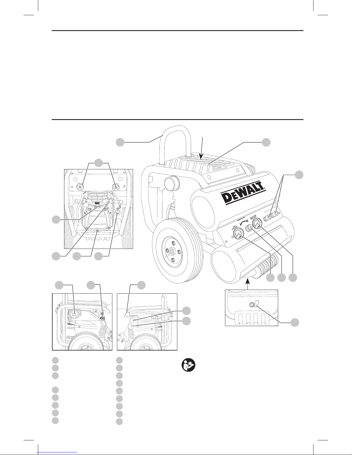
1
On/off switch
2
Air tank pressure gauge
3
Regulated pressure
gauge
4
Pressure regulator
5
Quick connects
6
Check valve
7
Safety valve
8
Air tank drain valve
9
Power cord wrap
10
Pressure switch
11
Pump oil dipstick
12
Pump oil drain plug
13
Motor reset
14
Air intake filter
15
Handle
16
Handle locking knobs
17
Top panel for cargo
Fig. A
342
NOT A
STEP
1715
16
12
6
13
11
8
14
7
9
10
1
5
Page 4

ENGLISH
2
SAVE ALL WARNINGS AND
INSTRUCTIONS FOR FUTURE
REFERENCE
DANGER: RISK OF EXPLOSION OR FIRE
What can happen How to prevent it
It is normal for electrical contacts
within the motor and pressure
switch to spark.
Always operate the compressor
in a well ventilated area free of
combustible materials, gasoline, or
solvent vapors.
If electrical sparks from compressor
come into contact with flammable
vapors, they may ignite, causing
fire or explosion.
If spraying flammable materials,
locate compressor at least 20 feet
(6.1 m) away from spray area.
An additional length of hose may
be required.
Store flammable materials
in a secure location away
from compressor.
Restricting any of the compressor
ventilation openings will cause
serious overheating and could
cause fire.
Never place objects against or on
top of compressor pump.
Operate compressor in an open
area at least 12" (30.5 cm) away
from any wall or obstruction that
would restrict the flow of fresh air
to the ventilation openings.
Operate compressor in a clean,
dry well ventilated area. Do not
operate unit indoors or in any
confined area.
Unattended operation of this
product could result in personal
injury or property damage.
To reduce the risk of fire, do
not allow the compressor to
operate unattended.
Always remain in attendance with
the product when it is operating.
Always turn off and unplug unit
when not in use.
CAUTION: RISK FROM NOISE
What can happen How to prevent it
Under some conditions and
duration of use, noise from
this product may contribute to
hearing loss.
Always wear certified safety
equipment: ANSI S12.6 (S3.19)
hearing protection.
DANGER: RISK TO BREATHING
(Asphyxiation)
What can happen How to prevent it
The compressed air directly from
your compressor is not safe for
breathing. The air stream may
contain carbon monoxide, toxic
vapors, or solid particles from
the air tank. Breathing these
contaminant's can cause serious
injury or death.
Air obtained directly from the
compressor should never be
used to supply air for human
consumption. In order to use air
produced by this compressor for
breathing, suitable filters and
in-line safety equipment must be
properly installed. In-line filters
and safety equipment used in
conjunction with the compressor
must be capable of treating air
to all applicable local and federal
codes prior to human consumption.
Sprayed materials such as paint,
paint solvents, paint remover,
insecticides, weed killers,
may contain harmful vapors
and poisons.
Work in an area with good cross
ventilation. Read and follow the
safety instructions provided on the
label or safety data sheets for the
materials you are spraying. Always
use certified safety equipment:
OSHA/MSHA/NIOSH respiratory
protection designed for use with
your specific application.
DANGER: RISK OF INJURY OR PROPERTY
DAMAGE WHEN TRANSPORTING
OR STORING
What can happen How to prevent it
Oil can leak or spill and could result
in fire or breathing hazard; serious
injury or death can result. Oil leaks
will damage carpet, paint or other
surfaces in vehicles or trailers.
Always place compressor
on a protective mat when
transporting to protect against
damage to vehicle from leaks.
Remove compressor from vehicle
immediately upon arrival at
your destination. Always keep
compressor level and never lie
on its side.
WARNING: RISK OF BURSTING
Air Tank: The air tank on your Air Compressor is designed
and may be UM coded (for units with air tanks greater
than 6 inch / 152 mm diameter) according to ASME
Section VIII, Div. 1 rules. All pressure vessels should
be inspected once every two years. To find your state
pressure vessels inspector, look under the Division of
Labor and Industries in the government section of a
phone book or call 1–800–4-
DeWALT
forassistance.
The following conditions could lead to a weakening of the
air tank, and result in a violent air tank explosion:
What can happen How to prevent it
Failure to properly drain condensed
water from air tank, causing rust
and thinning of the steel air tank.
Drain air tank daily or after each
use. If air tank develops a leak,
replace it immediately with
a new air tank or replace the
entire compressor.
Page 5

ENGLISH
3
Modifications or attempted repairs
to the air tank.
Never drill into, weld, or make
any modifications to the air tank
or its attachments. Never attempt
to repair a damaged or leaking air
tank. Replace with a new air tank.
Unauthorized modifications to
the safety valve or any other
components which control air
tank pressure.
The air tank is designed to
withstand specific operating
pressures. Never make adjustments
or parts substitutions to alter the
factory set operating pressures.
Attachments & accessories:
Exceeding the pressure rating of
air tools, spray guns, air operated
accessories, tires, and other
inflatables can cause them to
explode or fly apart, and could
result in serious injury.
Follow the equipment
manufacturers recommendation
and never exceed the maximum
allowable pressure rating of
attachments. Never use compressor
to inflate small low pressure
objects such as children’s toys,
footballs, basketballs, etc.
Tires:
Over inflation of tires could
result in serious injury and
property damage.
Use a tire pressure gauge to check
the tires pressure before each
use and while inflating tires; see
the tire sidewall for the correct
tire pressure.
NOTE: Air tanks, compressors
and similar equipment used to
inflate tires can fill small tires
similar to these very rapidly. Adjust
pressure regulator on air supply
to no more than the rating of the
tire pressure. Add air in small
increments and frequently use the
tire gauge to prevent over inflation.
WARNING: RISK OF ELECTRICAL SHOCK
What can happen How to prevent it
Your air compressor is powered
by electricity. Like any other
electrically powered device, If it
is not used properly it may cause
electric shock.
Never operate the compressor
outdoors when it is raining or in
wet conditions.
Never operate compressor with
protective covers removed
or damaged.
Repairs attempted by unqualified
personnel can result in serious
injury or death by electrocution.
Any electrical wiring or repairs
required on this product should
be performed by a DeWALT
factory service center or a DeWALT
authorized service center in
accordance with national and local
electrical codes.
Electrical Grounding:
Failure to provide adequate
grounding to this product
could result in serious injury or
death from electrocution. See
Grounding Instructions
under Installation.
Make certain that the electrical
circuit to which the compressor
is connected provides proper
electrical grounding, correct
voltage and adequate
fuse protection.
WARNING: RISK FROM FLYING OBJECTS
What can happen How to prevent it
The compressed air stream can
cause soft tissue damage to
exposed skin and can propel
dirt, chips, loose particles, and
small objects at high speed,
resulting in property damage or
personal injury.
Always wear certified safety
equipment: ANSI Z87.1 eye
protection (CAN/CSA Z94.3)
with side shields when using
the compressor.
Never point any nozzle or sprayer
toward any part of the body or at
other people or animals.
Always turn the compressor off and
bleed pressure from the air hose
and air tank before attempting
maintenance, attaching tools
or accessories.
WARNING: RISK OF HOT SURFACES
What can happen How to prevent it
Touching exposed metal such as
the compressor head, engine head,
engine exhaust or outlet tubes, can
result in serious burns.
Never touch any exposed metal
parts on compressor during or
immediately after operation.
Compressor will remain hot for
several minutes after operation.
Do not reach around protective
shrouds or attempt maintenance
until unit has been allowed to cool.
WARNING: RISK OF INJURY FROM LIFTING
What can happen How to prevent it
Serious injury can result from
attempting to lift too heavy
an object.
The compressor is too heavy
to be lifted by one person.
Obtain assistance from others
before lifting.
WARNING: RISK FROM MOVING PARTS
What can happen How to prevent it
Moving parts such as the pulley,
flywheel, and belt can cause
serious injury if they come into
contact with you or your clothing.
Never operate the compressor
with guards or covers which are
damaged or removed
Keep your hair, clothing, and
gloves away from moving parts.
Loose clothes, jewelry, or long hair
can be caught in moving parts.
Air vents may cover moving parts
and should be avoided as well.
Page 6

ENGLISH
4
Attempting to operate compressor
with damaged or missing parts or
attempting to repair compressor
with protective shrouds removed
can expose you to moving parts
and can result in serious injury.
Any repairs required on this
product should be performed by a
DeWALT factory service center or a
DeWALT authorized service center.
WARNING: RISK OF UNSAFE OPERATION
What can happen How to prevent it
Unsafe op er a tion of your air
compressor could lead to se ri ous
in ju ry or death to you or others.
Review and understand all
instructions and warnings in
this manual.
Be come fa mil iar with the op eration
and con trols of the air compressor.
Keep operating area clear of all
persons, pets, and obstacles.
Keep chil dren away from the air
compressor at all times.
Do not operate the product when
fatigued or under the influence
of alcohol or drugs. Stay alert at
all times.
Never defeat the safety fea tures of
this prod uct.
Equip area of operation with a
fire extinguisher.
Do not op er ate machine
with missing, broken, or
un authorized parts.
Never stand on the compressor.
WARNING: RISK OF FALLING
What can happen How to prevent it
A portable compressor can fall
from a table, workbench, or roof
causing damage to the compressor
and could result in serious injury or
death to the operator.
Always operate compressor in a
stable secure position to prevent
accidental movement of the unit.
Never operate compressor on a
roof or other elevated position.
Use additional air hose to reach
high locations.
SAVE THESE INSTRUCTIONS FOR
FUTURE USE
WARNING: Some dust created by power sanding,
sawing, grinding, drilling, and other construction
activities contains chemicals known to the State
of California to cause cancer, birth defects or
other reproductive harm. Some examples of these
chemicalsare:
• lead from lead-based paints,
• crystalline silica from bricks and cement and other
masonry products, and
• arsenic and chromium from chemicallytreatedlumber.
Your risk from these exposures varies, depending on how
often you do this type of work. To reduce your exposure to
these chemicals: work in a well ventilated area, and work with
approved safety equipment, such as those dust masks that are
specially designed to filter out microscopicparticles.
• Avoid prolonged contact with dust from power
sanding, sawing, grinding, drilling, and other
construction activities. Wear protective clothing and
wash exposed areas with soap and water. Allowing
dust to get into your mouth, eyes, or lay on the skin may
promote absorption of harmfulchemicals.
WARNING: Use of this tool can generate and/
or disperse dust, which may cause serious and
permanent respiratory or other injury. Always use
NIOSH/OSHA approved respiratory protection
appropriate for the dust exposure. Direct particles
away from face andbody.
COMPONENTS (FIG. A–G)
WARNING: Never modify the power tool or any part
of it. Damage or personal injury couldresult.
Refer to Figure A at the beginning of this manual for a
complete list ofcomponents.
Specifications
Model D55154
Weight 80 lbs. (36.3 kg)
Height 20.0" (508.0 mm)
Width 18.5" (469.9 mm)
Length 23.0" (584.2 mm)
Air Tank Capacity (Gallons) 4.0 (15.1 liters)
Approx Cut-In Pressure 95 PSI (655 kPa)
Approx. Cut-Out Pressure 125 PSI (861.8 kPa)
SCFM @ 100 PSI (689.5 Kpa) 3.8
Motor 1.1 HP (continuous)
Volts/Amps/Hertz 120V/14 A/60 Hz.
RPM 3450
Minumum Branch Circuit Requirement 15 Amp
Pump Oil Capacity 12 oz. (354.9 ml)
Duty Cycle 5 Minutes On /
5 Minutes Off
Page 7
ENGLISH
5
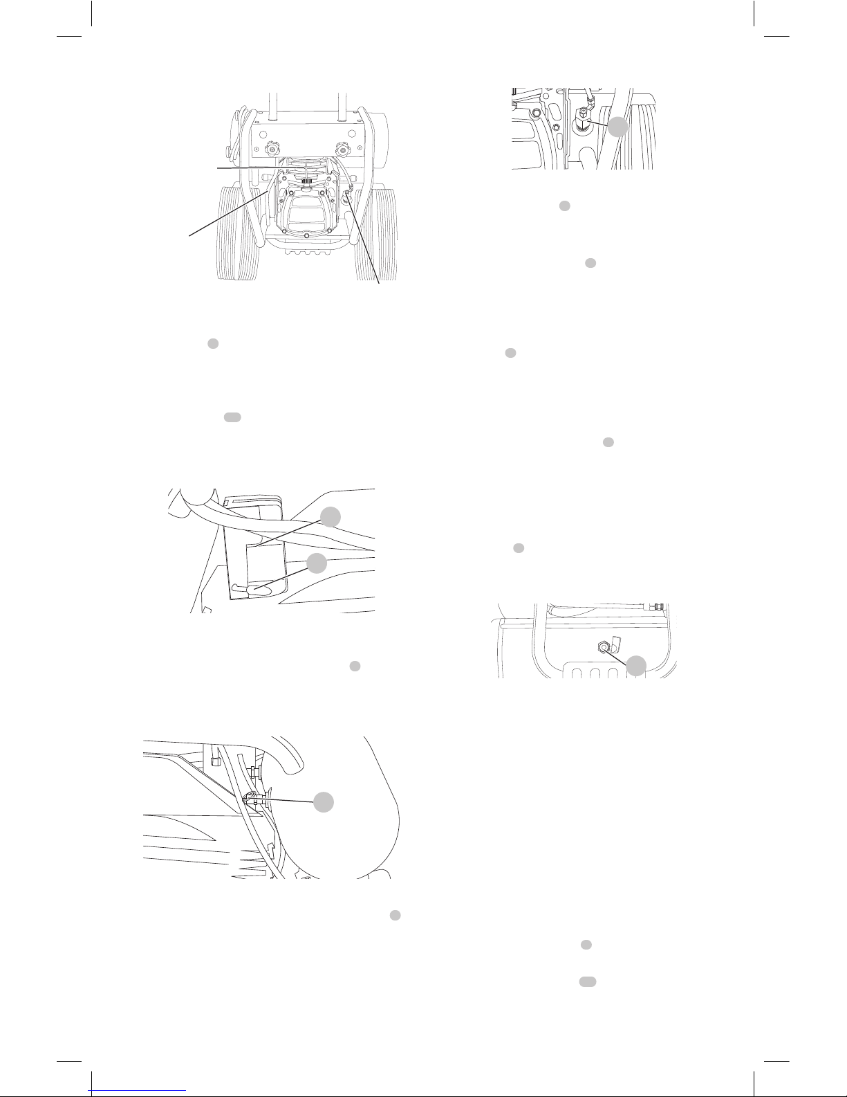
OUTLET TUBE
CHECK VALVE
PUMP CYLNDER
AND HEAD
Fig. B
On/Off Switch
Place this switch
1
in the ON position to provide automatic
power to the pressure switch and OFF to remove power at
the end of eachuse.
Pressure Switch
The pressure switch
10
automatically starts the motor
when the air tank pressure drops below the factory set cut-
in pressure. It stops the motor when the air tank pressure
reaches the factory set cut-outpressure.
Fig. C
10
1
Safety Valve
If the pressure switch does not shut off the air compressor
at its cut-out pressure setting, the safety valve
7
will
protect against high pressure by popping out at its factory
set pressure (slightly higher than the pressure switch cutoutsetting).
7
Fig. D
Check Valve
When the air compressor is operating, the check valve
6
is
open, allowing compressed air to enter the air tank. When
the air compressor reaches cut-out pressure, the check valve
closes, allowing air pressure to remain inside the airtank.
Fig. E
6
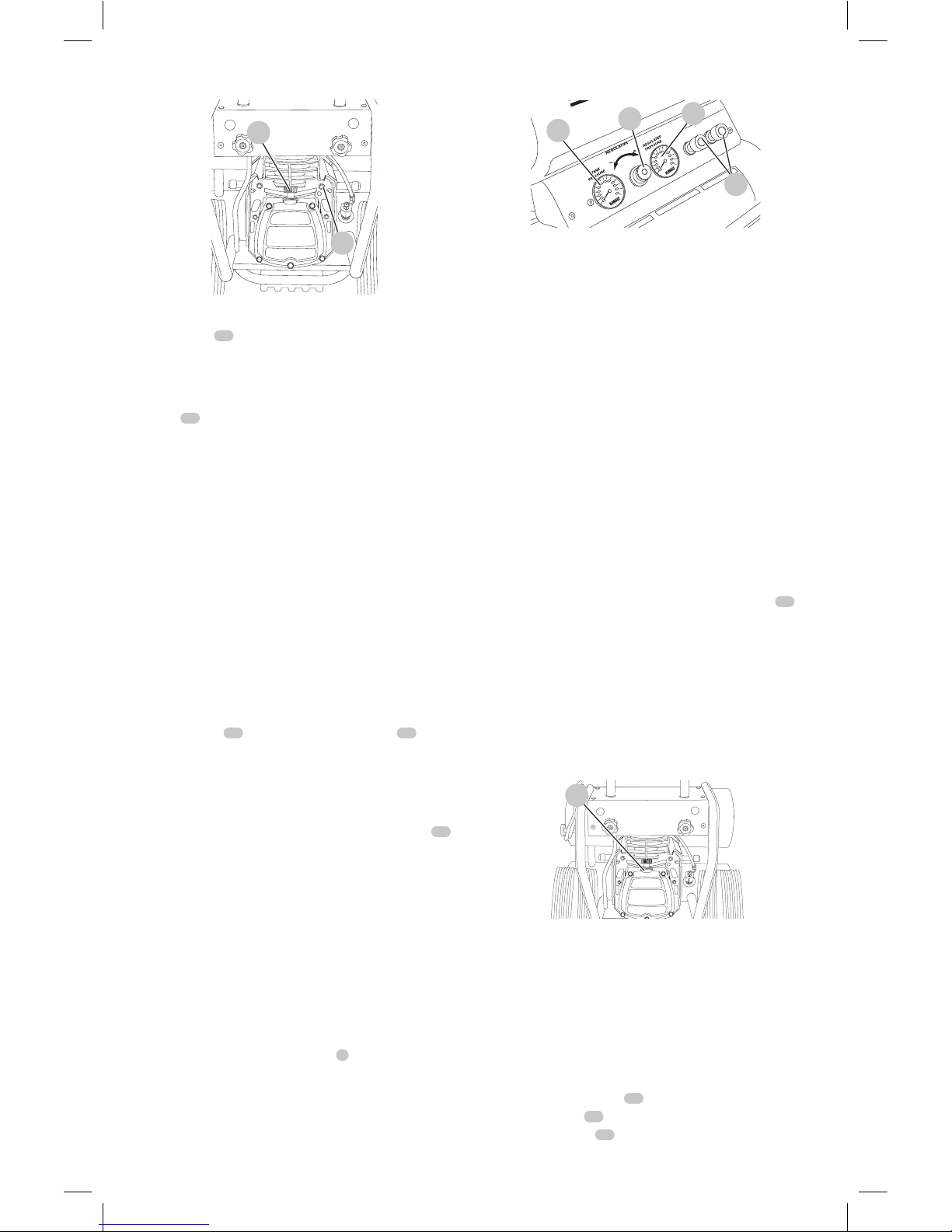
Tank Pressure Gauge
The tank pressure gauge
2
indicates the reserve air
pressure in thetank.
Regulated Pressure Gauge
The regulated pressure gauge
3
indicates the air pressure
available at the outlet side of the regulator. This pressure is
controlled by the regulator and is always less than or equal
to the tankpressure.
Regulator
The regulator
4
controls the air pressure shown on
the regulated pressure gauge. Turn regulator knob
clockwise to increase pressure and counterclockwise to
decreasepressure.
Universal Quick Connect Bodies
The universal quick connect body
5
accepts the three
most popular styles of quick connect plugs: Industrial,
automotive, and ARO. One hand push-to-connect operation
makes connections simple and easy. The two quick connect
bodies allow the use of two tools at the sametime.
Drain Valve
The drain valve
8
is located at the base of the air tank and
is used to drain condensation at the end of each use. See
Draining Air Tank underMaintenance.
8
Fig. F
Cooling System
This compressor contains an advanced design cooling
system. It is normal for this fan to blow air through the vent
holes in large amounts. The cooling system is working when
air isexpelled.
Air Compressor Pump
The pump compresses air into the air tank. Working air is
not available until the compressor has raised the air tank
pressure above that required at the airoutlet.
Motor Overload Protector
This motor has a manual thermal overload protector. If the
motor overheats for any reason, the overload protector
will shut off the motor. The motor must be allowed to cool
down before restarting. To restart:
1. Ensure the On/Off switch
1
is in the OFFposition.
2. Allow the motor tocool.
3. Depress the reset button
13
on themotor.
Page 8
ENGLISH
6
Fig. G
13
11
Oil Dipstick
The oil dipstick
11
indicates the amount of oil in the
pump. Check pump oil daily, see Compressor Pump Oil
underMaintenance.
Air Intake Filter
The filter
14
is designed to clean air entering the pump.
To ensure the pump continually receives a clean, cool, and
dry air supply the filter must always be clean and the filter
intake must be free fromobstructions.
ASSEMBLY AND ADJUSTMENTS
WARNING: To reduce the risk of serious personal
injury, turn unit off and disconnect it from
power source before making any adjustments or
removing/installing attachments or accessories.
An accidental start-up can causeinjury.
Assembly (Fig. A, H–M)
Installing Handle
CAUTION: Risk of personal injury. Avoid placing
hands between handle and top panel when
assembling to preventpinching.
1. Place handle
15
into bushings on top panel
17
.
2. Depress snap buttons and slide handle through first
bushings until it stops at secondbushings.
3. Reach under top panel and depress snap buttons again
and slide through secondbushings.
4. Pull handle all the way up until it stops. Turn knobs
16
to lock handle in place. IMPORTANT: Always pull
handle up and lock in place before using as adolly.
5. If not using the dolly feature, loosen knobs and push
handle down until itstops.
Installing Hoses
WARNING: Risk of unsafe operation. Firmly grasp
hose in hand when installing or disconnecting to
prevent hosewhip.
1. Ensure regulated pressure gauge reads 0 PSI (0kPa).
2. Grasp the hose at the quick connect plug and push the
plug into the quick connect body
5
. Coupler will snap
intoplace.
3. Grasp the hose and pull to ensure coupler isseated.
Fig. H
2
4
3
5
Disconnecting Hoses
WARNING: Risk of unsafe operation. Firmly grasp
hose in hand when installing or disconnecting to
prevent hosewhip.
1. Ensure regulated pressure gauge reads 0 PSI (0kPa).
2. Pull coupler on quick connect body back to release
quick connect plug onhose.
Lubrication and Oil
CAUTION: The compressor was shipped with oil in
the crankcase. A shipping plug is used to prevent oil
from leaking during shipment. Do not attempt to
operate this air compressor without first checking the
oil level. Serious damage can result from even limited
operation unless filled with oil and broken in correctly.
Closely follow Initial Set-up underOperation.
CAUTION: Use SAE 5W-40 full synthetic oil.
1. Place unit on a levelsurface.
2. Remove the shipping plug and install the dipstick
11
.
3. Remove the dipstick and check the oil level. Oil should
not exceed top raised line on dipstick. If oil is below
lower mark see Checking Oil under Compressor
Pump Oil underMaintenance.
NOTE: See Specifications for pump oilcapacity.
CAUTION: Risk of unsafe operation. Overfilling with
oil will cause premature compressor failure. Do
notoverfill.
Fig. I
11
Grounding Instructions
WARNING: Risk of electrical shock. In the event
of a short circuit, grounding reduces the risk
of shock by providing an escape wire for the
electric current. This air compressor must be
properlygrounded.
The portable air compressor is equipped with a cord having
a grounding wire with an appropriate groundingplug.
1. The cord set and plug
18
with this unit contains a
grounding pin
19
. This plug MUST be used with a
grounded outlet
20
.
Page 9

ENGLISH
7
Fig. J
18
20
19
IMPORTANT: The outlet being used must be installed and
grounded in accordance with all local codes andordinances.
2. Ensure the outlet being used has the same
configuration as the grounded plug. DO NOT USE
ANADAPTER.
3. Inspect the plug and cord before each use. Do not use if
there are signs ofdamage.
4. If these grounding instructions are not completely
understood, or if in doubt as to whether the compressor
is properly grounded, have the installation checked by a
qualifiedelectrician.
DANGER: Risk of electrical shock. IMPROPER
GROUNDING CAN RESULT IN ELECTRICALSHOCK.
• Do not modify the plug provided. If it does not
fit the available outlet, a correct outlet should be
installed by a qualifiedelectrician.
• Repairs to the cord set or plug MUST be made by a
qualifiedelectrician.
Extension Cords
Using extension cords is not recommended. The use of
extension cords will cause voltage to drop resulting in
power loss to the motor andoverheating.
Instead of using an extension cord, increase the working
reach of the air hose by attaching another length of hose to
its end. Attach additional lengths of hose asneeded.
If an extension cord must be used, be sure it is:
• a 3-wire extension cord that has a 3-blade grounding
plug, and a 3-slot receptacle that will accept the plug
on the product
• in good condition
• plug is not worn
• no longer than 50 feet (15,2 m)
• 12 gauge (AWG) or larger. (Wire size increases as gauge
number decreases. 10 AWG may also be used. DO NOT
USE 14, 16 OR 18 AWG.)
Voltage and Circuit Protection
Refer to the Voltage and Minimum Branch Circuit
Requirements underSpecifications.
CAUTION: Certain air compressors can be operated
on a 15 amp circuit if the following conditions
aremet.
• Voltage supply to circuit must comply with the
National ElectricalCode.
• Circuit is not used to supply any other
electricalneeds.
• Extension cords comply withspecifications.
• Circuit is equipped with a 15 amp circuit breaker
or 15 amp time delay fuse. NOTE: If compressor
is connected to a circuit protected by fuses, use
only time delay fuses. Time delay fuses should be
marked “D” in Canada and “T” in theUS.
If any of the above conditions cannot be met, or
if operation of the compressor repeatedly causes
interruption of the power, it may be necessary to
operate it from a 20 amp circuit. It is not necessary to
change the cordset.
Compatibility
Air tools and accessories that are run off the compressor
must be compatible with petroleum-based products. If you
suspect that a material is not compatible with petroleum
products, an air line filter for removal of moisture and oil
vapor in compressed air isrequired.
NOTE: Always use an air line filter to remove moisture and
oil vapor when sprayingpaint.
Location
Place the air compressor in a clean, dry and well ventilated
area at least 12" (30.5 cm) away from the wall or other
obstructions that will interfere with the flow of air. Keep the
compressor away from areas that have dirt and/or volatile
fumes in the atmosphere. These impurities may clog the
intake filter and valves, causing inefficientoperation.
The air compressor pump and shroud are designed to
allow for proper cooling. The ventilation openings on the
compressor are necessary to maintain proper operating
temperature. Do not place rags or other containers on or
near theseopenings.
Place the air compressor on a flat surface resting on the
rubberfeet.
Noise Considerations
Consult local officials for information regarding acceptable
noise levels in your area. To reduce excessive noise, use
vibration mounts or silencers, relocate the unit or construct
total enclosures or baffle walls. Contact a
DeWALT
service
center or call 1–800–4-
DeWALT
forassistance.
Electrical
Refer to all safety instructions before using unit. Observe
extension cord safety instructions if necessary. Always move
the On/Off switch
1
to the OFF position before removing
the plug from theoutlet.
Transporting
When transporting the compressor in a vehicle, trailer, etc.
ensure that the air tank is drained and the unit is secured
and placed on a flat horizontalsurface.
NOTE: Use recommended tie down points
21
when
transporting. Use care when driving so to avoid tipping the
unit over in the vehicle. Damage can occur to the unit or
surrounding items if unit istipped.
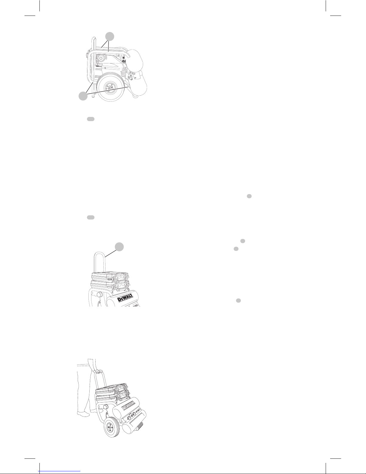
Lifting
Always use two people when lifting and lift from the
recommended lift points
22
.
Page 10
ENGLISH
8
22
21
Fig. K
Moving
1. Grasp handle
15
of compressor and pull up until it
stops. Turn knobs to lock handle inplace.
2. Grasp handle and tilt compressor so unit can be rolled
on thetires.
WARNING: Risk of unsafe operation. Ensure proper
footing and use caution when rolling compressor so
that unit does not tip or cause loss ofbalance.
3. When location is reached slowly lower compressor
to ground. Always store compressor in a
horizontalposition.
NOTE: Should the unit tip over, hard starting and smoking
will occur due to oilspillage.
Dolly Feature
1. Grasp handle
15
of compressor and pull up
until it stops. Turn knobs to lock handle in place.
IMPORTANT:Always pull handle up and lock in place
before using as adolly.
Fig. L
15
2. Place cargo onto top panel ofcompressor.
3. Secure cargo to top panel with retention straps. Hook
cargo retention straps into positioning holes in top
panel. NOTE: Retention straps to secure cargo may be
purchase from a local hardware store or home center in
a variety ofsizes.
Fig. M
CAUTION: Risk of unsafe operation. Do not transport
unsecuredcargo.
CAUTION: Risk of unsafe operation. Load limit is
100lbs. (45.4kg) do notexceed.
4. With cargo secured, grasp handle and tilt compressor so
unit can be rolled on thetires.
WARNING: Risk of unsafe operation. Ensure proper
footing and use caution when rolling compressor so
that unit does not tip or cause loss ofbalance.
5. When location is reached slowly lower compressor
to ground. Always store compressor in a
horizontalposition.
OPERATION
WARNING: To reduce the risk of serious personal
injury, turn unit off and disconnect it from
power source before making any adjustments or
removing/installing attachments or accessories.
An accidental start-up can causeinjury.
Preparation For Use
Pre-Start Checklist (Fig. A)
1. Ensure the On/Off switch
1
is in the OFFposition.
2. Plug the power cord into the correct branch circuit
receptacle. See Voltage and Circuit Protection
underAssembly and Adjustments.
3. Ensure air tank is drained, see Draining Air Tank
underMaintenance.
4. Ensure the drain valve
8
isclosed.
5. Ensure safety valve
7
is functioning properly, see
Checking Safety Valve underMaintenance.
6. Check pump oil level, see Compressor Pump Oil
underMaintenance.
CAUTION: Do not operate without oil or with
inadequate oil.
DeWALT
is not responsible for
compressor failure caused by inadequateoil.
7. Turn regulator knob
4
counterclockwise until fully
closed. Ensure regulated pressure gauge reads 0 PSI
(0kPa).
8. Attach hose andaccessories.
WARNING: Risk of unsafe operation. Firmly grasp
hose in hand when installing or disconnecting to
prevent hosewhip.
9. Ensure all covers and labels are in place, legible (for
labels) and securely mounted. Do not use compressor
until all items have beenverified.
WARNING: Risk of bursting. Too much air pressure
causes a hazardous risk of bursting. Check the
manufacturer’s maximum pressure rating for air tools
and accessories. The regulator outlet pressure must
never exceed the maximum pressurerating.
Initial Set-up
(Fig. A)
WARNING: Do not operate this unit until you read
and understand this instruction manual for safety,
operation and maintenanceinstructions.
Page 11

ENGLISH
9
Break-in Procedure
CAUTION: RISK OF PROPERTY DAMAGE. Serious
damage may result if the following break-in
instructions are not closelyfollowed.
This procedure is required before the air compressor is put
into service for the first time and when the check valve or a
compressor pump/motor has beenreplaced.
1. Ensure the On/Off switch
1
is in the OFFposition.
NOTE: If hose is not connected to Quick Connect body,
pull coupler back until it clicks to prevent air from escaping
through the quickconnect.
2. Plug the power cord into the correct branch circuit
receptacle. See Voltage and Circuit Protection under
Assembly and Adjustments.
3. Open the drain valve (counter-clockwise) fully to permit
air to escape and prevent air pressure build up in the air
tank during the break-inperiod.
4. Move the On/Off switch to the ON position. The
compressor willstart.
5. Run the compressor for 20minutes.
6. After 20 minutes, close the drain valve by turning
clockwise. The tank will fill to cut-out pressure and the
motor willstop.
7. Compressed air will be available until it is used or
bledoff.
Operating Procedures
Start-up (Fig. A)
1. Follow Pre-Start Checklist under Preparation forUse.
2. Move the On/Off switch
1
to the ON position and
allow tank pressure to build. Motor will stop when tank
pressure reaches cut-outpressure.
CAUTION: Risk of unsafe operation. Compressed air
from the unit may contain wa ter condensation and oil
mist. Do not spray un fil tered air at an item that could
be damaged by moisture. Some air op er ated tools or
de vic es may require filtered air. Read the in struc tions
for the air tool ordevice.
3. Adjust regulator
4
to desired setting. See Regulator
underComponents.
Shut-down (Fig. A)
1. Move On/Off switch
1
is in the OFF position. NOTE: If
finished using compressor, follow Steps 2 -6.
2. Turn regulator knob
4
counterclockwise until fully
closed. Ensure regulated pressure gauge reads 0 PSI
(0kPa).
3. Remove hose andaccessory.
4. Drain the air tank, see Draining Air Tank under
Maintenance. Ensure air tank pressure gauge reads
0PSI (0kPa).
WARNING: Risk of bursting. Drain air tank daily.
Water will condense in air tank. If not drained, water
will corrode and weaken the air tank causing a risk of
air tankrupture.
5. Allow the compressor to cooldown.
6. Wipe air compressor clean and store in a safe, nonfreezingarea.
MAINTENANCE
WARNING: To reduce the risk of serious personal
injury, turn unit off and disconnect it from
power source before making any adjustments or
removing/installing attachments or accessories.
An accidental start-up can causeinjury.
The following procedures must be followed when
maintenance or service is performed on the aircompressor.
1. Ensure On/Off switch is in the OFFposition.
2. Remove air compressor plug fromoutlet.
3. Drain airtank.
4. Allow air compressor to cool down before
startingservice.
NOTE: All compressed air systems contain maintenance
parts (e.g., oil, filters, separators) that are periodically
replaced. These used parts may contain substances that are
regulated and must be disposed of in accordance with local,
state, and federal laws andregulations.
NOTE: Take note of the positions and locations of parts
during disassembly to make reassemblyeasier.
NOTE: Any service operations not included in this section
should be performed by a
DeWALT
factory service center or
a
DeWALT
authorized servicecenter.
MAINTENANCE CHART
Procedure Daily Weekly Monthly 1 year or 200
Hours
Check safety valve
X
Inspect air filter +
X
Drain air tank
X
Check pump oil level
X
Change pump oil**+ X
Oil leak inspection
X
Check for unusual noise/
vibration
X
Check for air leaks*
X
Clean compressor exterior
X
* To check for air leaks apply a solution of soapy water around joints.
While compressor is pumping to pressure and after pressure cuts out,
look for air bubbles to form.
** The pump oil must be changed after the first 20 hours of operation.
Thereafter, when using SAE 5W-40 full synthetic oil, change oil every
200 hours of operation or once a year, whichever comes first.
+ Perform more frequent in dusty or humid conditions
Checking Safety Valve (Fig. B)
WARNING: Hot surfaces. Risk of burn. Aftercooler,
pump head, and surrounding parts are very hot, do
not touch (see the Hot Surfaces identified in Fig.B).
Allow compressor to cool prior toservicing.
Page 12
ENGLISH
10
WARNING: Risk of bursting. If the safety valve does
not work properly, over-pressurization may occur,
causing air tank rupture or anexplosion.
Before starting compressor, pull the ring on the safety
valve to make sure that the safety valve operates freely. If
the valve is stuck or does not operate smoothly, it must be
replaced with the same type ofvalve.
Checking Air Filter Element (Fig. A, B)
WARNING: Hot surfaces. Risk of burn. Aftercooler,
pump head, and surrounding parts are very hot, do
not touch (see the Hot Surfaces identified in Fig.B).
Allow compressor to cool prior toservicing.
1. Ensure the On/Off switch
1
is in the OFFposition.
2. Allow unit tocool.
3. Remove air filter
14
fromunit.
4. Carefully pry filter top frombase.
5. Remove element from filterbase.
6. If element needs cleaning, blow out with air. Replace
if needed. Purchase replacement parts from your local
dealer or authorized service center. Always use identical
replacementparts.
7. Place element back in filterbase.
8. Snap filter top to filterbase.
9. Reassemble air filter to unit. Ensure exhaust outlet
pointsdown.
CAUTION: Risk of unsafe operation. Do not operate
without air inletfilter.
Draining Air Tank (Fig. A)
WARNING: Risk of unsafe operation. Risk from
noise. Air tanks contain high pressure air. Keep face
and other body parts away from outlet of drain. Use
safety glasses [ANSI Z87.1 (CAN/CSA Z94.3)] when
draining as debris can be kicked up into face. Use ear
protection [ANSI S12.6 (S3.19)] as air flow noise is loud
whendraining.
NOTE: All compressed air systems generate condensate
that accumulates in any drain point (e.g. tanks, filter,
aftercoolers, dryers). This condensate contains lubricating
oil and/or substances which may be regulated and must be
disposed of in accordance with local, state, and federal laws
andregulations.
1. Ensure On/Off switch is in the OFFposition.
2. Move compressor into an inclined position so drain
valve
8
is at the lowest point (this will assist in
removing moisture, dirt, etc. from air tanks)
3. Place a suitable container under the drain valve to
catchdischarge.
4. Grasp knurled knob on drainvalve.
5. Slowly rotate knob to gradually bleed air from airtank.
WARNING: Risk of bursting. Drain air tank daily.
Water will condense in air tank. If not drained, water
will corrode and weaken the air tank causing a risk of
air tankrupture.
CAUTION: Risk of property damage. Drain water
from air tank may contain oil and rust, which can
causestains.
6. When air tank pressure gauge reads 10 PSI (68,9 kPa),
rotate valve to the fully openposition.
7. Close drain valve whenfinished.
Compressor Pump Oil (Fig. B, N)
Checking Oil
WARNING: Hot surfaces. Risk of burn. Aftercooler,
pump head, and surrounding parts are very hot, do
not touch (see the Hot Surfaces identified in Fig.B).
Allow compressor to cool prior toservicing.
1. Ensure On/Off switch is in the OFFposition.
2. Place unit on a flat levelsurface.
3. Remove dipstick
11
and wipeclean.
4. Reinsert dipstick fully into oil fill port for a few seconds
to allow oil to collect on thedipstick.
5. Remove oil dipstick to read oil level. Oil should not
exceed top raised line on dipstick. If oil is below lower
mark, add same type of oil in crankcase and follow Steps
4 - 6. NOTE: When filling the crankcase, the oil flows
very slowly into the pump. If the oil is added too quickly,
it will overflow and appear to befull.
CAUTION: Risk of unsafe operation. Overfilling with
oil will cause premature compressor failure. Do
notoverfill.
6. Replacedipstick.
MAX
MIN
11
12
Fig. N
Changing Oil
NOTE: Pump oil contains substances that are regulated
and must be disposed of in accordance with local, state and
federal laws andregulations.
WARNING: Hot surfaces. Risk of burn. Aftercooler,
pump head, and surrounding parts are very hot, do
not touch (see the Hot Surfaces identified in Fig.B).
Allow compressor to cool prior toservicing.
1. Ensure On/Off switch is in the OFFposition.
2. Allow the unit tocool.
3. Remove air compressor plug fromoutlet.
4. Drain airtank.
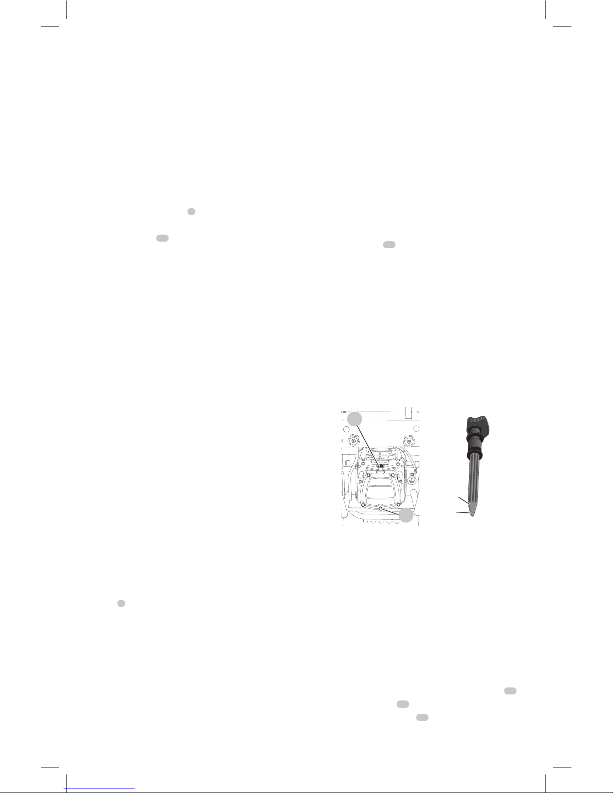
5. Locate a suitable container under pump drain plug
12
.
6. Remove the dipstick
11
fromcrank case.
7. Remove the oil drain plug
12
.
Page 13

ENGLISH
11
8. Allow ample time for all oil to drain out. (Tilting
the compressor towards the drain plug will assist
indraining.)
9. Install the oil drainplug.
10. Fill pump using SAE 5W-40 full synthetic oil.
11. Replacedipstick.
Cleaning
WARNING: Blow dirt and dust out of all air vents with
clean, dry air at least once a week. To minimize the risk
of eye injury, always wear ANSI Z87.1 approved eye
protection when performingthis.
WARNING: Never use solvents or other harsh
chemicals for cleaning the non-metallic parts of
the tool. These chemicals may weaken the plastic
materials used in these parts. Use a cloth dampened
only with water and mild soap. Never let any liquid
get inside the tool; never immerse any part of the tool
into aliquid.
Accessories
WARNING: Since accessories, other than those
offered by
DeWALT
, have not been tested with this
product, use of such accessories with this tool could be
hazardous. To reduce the risk of injury, only
DeWALT
recommended accessories should be used with
thisproduct.
Recommended accessories for use with your tool
are available at extra cost from your local dealer or
authorized service center. If you need assistance in
locating any accessory, please contact
DeWALT
Industrial
Tool Co., 701East Joppa Road, Towson, MD 21286, call
1-800-4-
DeWALT
(1-800-433-9258) or visit our website:
www.dewalt.com.
Repairs
The charger and battery pack are notserviceable.
WARNING: To assure product SAFETY and
RELIABILITY, repairs, maintenance and adjustment
(including brush inspection and replacement, when
applicable) should be performed by a
DeWALT
factory
service center or a
DeWALT
authorized service center.
Always use identical replacementparts.
Register Online
Thank you for your purchase. Register your product nowfor:
• WARRANTY SERVICE: Registering your product will
help you obtain more efficient warranty service in case
there is a problem with yourproduct.
• CONFIRMATION OF OWNERSHIP: In case of
an insurance loss, such as fire, flood or theft, your
registration of ownership will serve as your proof
ofpurchase.
• FOR YOUR SAFETY: Registering your product will
allow us to contact you in the unlikely event a safety
notification is required under the Federal Consumer
SafetyAct.
Register online at www.dewalt.com/register.
Three Year Limited Warranty
DeWALT
will repair, without charge, any defects due to
faulty materials or workmanship for three years from the
date of purchase. This warranty does not cover part failure
due to normal wear or tool abuse. For further detail of
warranty coverage and warranty repair information, visit
www.dewalt.com or call 1-800-4-
DeWALT
(1-800-433-9258).
This warranty does not apply to accessories or damage
caused where repairs have been made or attempted by
others. This warranty gives you specific legal rights and
you may have other rights which vary in certain states
orprovinces.
In addition to the warranty,
DeWALT
tools are covered
byour:
1 YEAR FREE SERVICE
DeWALT
will maintain the tool and replace worn parts
caused by normal use, for free, any time during the first year
afterpurchase.
90 DAY MONEY BACK GUARANTEE
If you are not completely satisfied with the performance of
your
DeWALT
Power Tool, Laser, or Nailer for any reason, you
can return it within 90 days from the date of purchase with
a receipt for a full refund – no questionsasked.
LATIN AMERICA: This warranty does not apply to products
sold in Latin America. For products sold in Latin America,
see country specific warranty information contained in
the packaging, call the local company or see website for
warrantyinformation.
FREE WARNING LABEL REPLACEMENT: If your warning
labels become illegible or are missing, call 1-800-4-
DeWALT
(1-800-433-9258) for a freereplacement.
Glossary
CFM: Cubic feet perminute.
SCFM: Standard cubic feet per minute; a unit of measure of
airdelivery.
PSI: Pounds per square inch; a unit of measure ofpressure.
kPa (kilopascal): Metric pressure measurement.
1kilopascal equal 1000pascals.
Code Certification: Products that bear one or more of the
following marks: UL, CUL, ETL, CETL, have been evaluated
by OSHA certified independent safety laboratories and
meet the applicable Underwriters Laboratories Standards
forSafety.
Cut-In Pressure: While the motor is off, air tank pressure
drops when accessory is used. When the tank pressure
drops to a certain low level the motor will restart
automatically. The low pressure at which the motor
automatically restarts is called cut-inpressure.
Cut-Out Pressure: When an air compressor is turned on
and begins to run, air pressure in the air tank begins to
build. It builds to a certain high pressure before the motor
automatically shuts off, protecting your air tank from
pressure higher than its capacity. The high pressure at which
the motor shuts off is called cut-outpressure.
Branch Circuit: The circuit carrying electricity from
electrical panel tooutlet.
Page 14

ENGLISH
12
Duty Cycle: For proper operation of your air compressor, it
is recommended that a 50% duty cycle be maintained; that
is, the air compressor should not run more than 5 minutes
in any 10 minuteperiod.
Troubleshooting Guide
This section provides a list of the more frequently encountered malfunctions, their causes and corrective actions. The
operator or maintenance personnel can perform some corrective actions, and others may require the assistance of a
qualified
DeWALT
technician or yourdealer.
Problem Code
Excessive air tank pressure-safety valve pops off 1, 2
Air leaks 3
Air leaks in air tank or at air tank welds 4
Air leaks between head and valve plate 5
Air leaks from safety valve 6
Knocking noise 6,16,17
Pressure reading on the regulated pressure gauge drops when an accessory is used 7
Compressor is not supplying enough air to operate accessories 8, 9, 10, 11, 12, 15
Regulator knob has continuous air leak 13
Regulator will not shut off air outlet 13
Moisture in pump crankcase 14,18
Motor will not run 11, 19, 20, 21, 22, 23, 24, 25, 26
Troubleshooting Codes
CODE POSSIBLE CAUSE POSSIBLE SOLUTION
1 Pressure switch does not shut off motor when compressor
reaches cut-out pressure
Set the On/Off switch to OFF, if the unit does not shut off contact a DeWALT factory
service center or a DeWALT authorized service center.
2 Pressure switch cut-out too high Contact a DeWALT factory service center or a DeWALT authorized service center.
3 Tube fittings are not tight enough Tighten fittings where air can be heard escaping. Check fittings with soapy water
solution. Do Not Overtighten.
4 Defective air tank Air tank must be replaced. Do not repair the leak.
WARNING: Risk of bursting. Do not drill into, weld or otherwise modify
air tank or it will weaken. The air tank can rupture or explode.
5 Leaking seals Contact a DeWALT factory service center or a DeWALT authorized service center.
6 Defective safety valve Operate safety valve manually by pulling on ring. If valve still leaks, it must
be replaced.
7 Regulator is not adjusted correctly for accessory being used It is normal for some pressure drop to occur when an accessory is used, adjust the
regulator as instructed in Regulator under Features if pressure drop is excessive.
NOTE: Adjust the regulated pressure under flow conditions while accessory is
being used.
8 Prolonged excessive use of air Decrease amount of air usage.
9 Compressor is not large enough for accessory Check the accessory air requirement. If it is higher than the CFM or
pressure supplied by your air compressor, a larger compressor is needed to
operate accessory.
10 Hole in air hose Replace air hose.
11 Check valve restricted Remove, clean or replace.
12 Air leaks Tighten fittings.
13 Regulator is damaged Replace.
14 Unit operating in damp or humid conditions Move unit to a dry well ventilated area.
15 Restricted air intake filter Clean or replace air intake filter.
Page 15

ENGLISH
13
CODE POSSIBLE CAUSE POSSIBLE SOLUTION
16 Engine or pump oil is low Add same type of oil in crankcase to pump. See Compressor Pump Oil
under Maintenance.
17 Carbon build-up in pump. Contact a DeWALT factory service center or a DeWALT authorized service center.
18 Detergent type oil being used in pump Drain oil and refill pump using SAE 5W-40 full synthetic oil.
19 Motor overload protection switch has tripped See Motor Overload under Components.
20 Extension cord is wrong length or gauge Check for proper gauge wire and cord length. See Extension Cords
under Assembly and Adjustments.
21 Loose electrical connections Contact a DeWALT factory service center or a DeWALT authorized service center.
22 Possible defective motor or starting capacitor Contact a DeWALT factory service center or a DeWALT authorized service center.
23 Paint spray on internal motor parts Contact a DeWALT factory service center or a DeWALT authorized service center. Do
not operate the compressor in the paint spray area. See flammable vapor warning.
24 Fuse blown, circuit breaker tripped Check fuse box for blown fuse and replace as necessary. Reset circuit breaker. Do
not use a fuse or circuit breaker with higher rating than that specified for your
particular branch circuit.
Check for proper fuse. Use only a time delay fuse.
Check for low voltage conditions and/or proper extension cord.
Disconnect the other electrical appliances from circuit or operate the compressor on
its own branch circuit.
25 Tank pressure exceeds pressure switch cut-in pressure Motor will start automatically when tank pressure drops below cut-in pressure of
pressure switch.
26 Pressure release valve on pressure switch has not unloaded
head pressure
Set the On/Off switch to OFF. If the valve does not open, replace switch. Contact a
DeWALT factory service center or a DeWALT authorized service center.
Page 16

FRANÇAIS
14
Définitions : symboles et termes d'alarmes sécurité
Ces guides d'utilisation utilisent les symboles et termes d'alarmes sécurité suivants pour vous prévenir de situations
dangereuses et de risques de dommages corporels ou matériels.
DANGER: indique une situation dangereuse imminente qui, si elle n’est pas évitée, entraînera la mort ou des
blessuresgraves.
AVERTISSEMENT: indique une situation potentiellement dangereuse qui, si elle n’est pas évitée, pourrait entraîner la
mort ou des blessuresgraves.
ATTENTION: indique une situation potentiellement dangereuse qui, si elle n’est pas évitée, pourrait entraîner des
blessures légères oumodérées.
(Si utilisé sans aucun terme) Indique un message propre à la sécurité.
AVIS : indique une pratique ne posant aucun risque de dommages corporels mais qui par contre, si rien n’est fait
pour l’éviter, pourrait poser des risques de dommages matériels.
AVERTISSEMENT! lire tous les avertissements de
sécurité et toutes les directives. Le non-respect des
avertissements et des directives pourrait se solder par un
choc électrique, un incendie et/ou une blessuregrave.
AVERTISSEMENT : afin de réduire le risque de blessures,
lire le mode d’emploi del’outil.
AVERTISSEMENT : Ce produit contient des produits
chimiques reconnus dans l’État de la Californie pour
causer le cancer et des anomalies congénitales ou autres
effets nuisibles sur la reproduction. Lavez-vous les mains
aprèsmanutention.
AVERTISSEMENT : Certaines poussières comme l’amiante
ou le plomb dans la peinture à base de plomb contiennent
des produits chimiques reconnus dans l’État de la Californie
pour causer le cancer et des anomalies congénitales ou
autres effets nuisibles sur la reproduction.
1
Interrupteur Marche/Arrêt
2
Manomètre du réservoir
d’air
3
Manomètre régulé
4
Régulateur de pression
5
Branchements rapides
6
Clapet
7
Soupape de sûreté
8
Soupape de purge du
réservoir d’air
9
Rembobineur de cordon
d’alimentation
10
Manocontacteur
11
Jauge graduée de l’huile
de la pompe
12
Bouchon de vidange
d’huile de la pompe
13
Réinitialisation du moteur
14
Filtre d’admission d’air
15
Poignée
16
Boutons de verrouillage
de la poignée
17
Panneau supérieur pour le
transport
Fig. A
342
PAS UNE
ÉTAPE
1715
16
12
6
13
11
8
14
7
9
10
1
5
Page 17

FRANÇAIS
15
CONSERVER TOUS LES
AVERTISSEMENTS ET TOUTES
LES DIRECTIVES POUR UN USAGE
ULTÉRIEUR
DANGER : RISQUE D’EXPLOSION
OU D’INCENDIE
Ce qui peut se produire Comment l’Éviter
Il est normal que des contacts
électriques dans le moteur
et le manocontacteur fassent
une étincelle.
Faites toujours fonctionner le
compresseur dans une zone bien
aérée sans matière combustible,
essence ou vapeur de solvant.
Si une étincelle électrique
provenant du compresseur
entre en contact avec des
vapeurs inflammables, elle peut
s’enflammer et causer un incendie
ou une explosion.
Si vous aspergez des matériaux
inflammables, placez le
compresseur à au moins 6,1 m
(20 pieds) de la zone pulvérisée.
Il est possible que vous ayez
besoin d’une longueur de
tuyau additionnelle.
Entreposez les matières
inflammables dans un
endroit sécuritaire, éloigné
du compresseur.
Le fait de limiter les ouvertures
d’aération de compresseur causera
une importante surchauffe et
pourrait causer un incendie.
Ne jamais placer d'objets contre
la pompe du compresseur ou sur
celle-ci.
Faites fonctionner le compresseur
dans un endroit aéré à au moins
30,5 cm (12 po) du mur ou de
l’obstruction qui pourrait limiter le
débit d’air frais dans les ouvertures
d’aération.
Faites fonctionner le compresseur
dans un endroit propre, sec et bien
aéré. Ne pas utiliser l’appareil à
l’intérieur ou dans un endroit exigu.
Le fonctionnement de ce produit
sans surveillance pourrait se solder
par des blessures personnelles ou
des dommages à la propriété. Afin
de réduire le risque d’incendie,
ne pas laisser le compresseur
fonctionner sans surveillance.
Être toujours présent lorsque le
produit est en marche.
Toujours éteindre et débrancher
l'appareil si non utilisé.
ATTENTION : RISQUE ASSOCIÉ
AU BRUIT
Ce qui peut se produire Comment l’Éviter
Dans certaines conditions et selon
la durée d’utilisation, le bruit
provoqué par ce produit peut
contribuer à une perte auditive.
Toujours utiliser un équipement de
sécurité homologué : protection
auditive conforme à la norme ANSI
S12.6 (S3.19).
DANGER: RISK TO BREATHING
(Asphyxiation)
Ce qui peut se produire Comment l’Éviter
Il est dangereux de respirer l’air
comprimé sortant du compresseur.
Le flux d’air peut contenir du
monoxyde de carbone, des vapeurs
toxiques ou des particules solides
provenant du réservoir d’air.
L’inhalation de ces contaminants
peut provoquer de sérieuses
blessures, voire un décès.
L’air qui s’obtient directement du
compresseur ne devrait jamais être
utilisé pour alimenter l’air destiné
à la consommation humaine.
Pour utiliser l’air produit par le
compresseur pour la respiration,
installer correctement des filtres
convenables et un équipement
de sécurité en ligne. Les filtres en
ligne et l’équipement de sécurité
utilisés avec le compresseur
doivent être capables de traiter l’air
conformément à tous les codes
locaux et fédéraux en vigueur avant
toute consommation humaine.
Les matériaux vaporisés comme la
peinture, les solvants de peinture,
les décapants, les insecticides, les
herbicides, pourraient contenir des
vapeurs nocives et du poison.
Travailler dans un endroit
ayant une bonne ventilation
transversale. Lire et respecter
les directives en matière de
sécurité imprimées sur l’étiquette
ou les fiches signalétiques des
matériaux qui sont pulvérisés.
Toujours utiliser un équipement
de sécurité homologué : une
protection respiratoire conforme
aux normes OSHA/MSHA/NIOSH,
conçue spécifiquement pour une
utilisation particulière.
DANGER : RISQUE DE BLESSURES OU DE
DOMMAGES À LA PROPRIÉTÉ LORS DU
TRANSPORT OU DU RANGEMENT
Ce qui peut se produire Comment l’Éviter
L’huile peut fuire ou se déverser.
Cela pourrait se solder par un
incendie ou un danger d’inhalation;
des blessures graves ou un décès.
Les fuites d’huile endommageront
le tapis, la peinture ou toutes
autres surfaces de véhicules ou
de remorques.
Toujours installer le compresseur
sur un revêtement protecteur
lors du transport pour protéger
le véhicule de tous dommages
associés aux fuites. Retirer
immédiatement le compresseur du
véhicule dès l’arrivée à destination.
Toujours tenir le compresseur à
niveau et ne jamais le déposer sur
son côté.
Page 18

FRANÇAIS
16
AVERTISSEMENT : RISQUE D’ÉCLATEMENT
Réservoir d’air : Le réservoir dont est doté le
compresseur d’air porte le code « UM » (dans le cas
d’appareils munis de réservoirs supérieurs à 152 mm
(6 po) de diamètre) et il est conçu conformément à la
section VII Div. 1 de l’ASME. Tous les récipients sous
pression devraient être inspectés une fois tous les
deux ans. Pour localiser l’inspecteur des récipients sous
pression de votre région, consulter la section appropriée
des organismes gouvernementaux de l’annuaire
téléphonique ou composer le 1–800–4-
DeWALT
pour
obtenir de l’aide.
Les conditions indiquées ci-après pourraient affaiblir le
réservoir d’air et se solder par une violente explosion de
celui-ci :
Ce qui peut se produire Comment l’Éviter
L’eau condensée n’est pas
correctement vidangée du réservoir
d’air provoquant ainsi la formation
de rouille et un amincissement du
réservoir d’air en acier.
Vidanger le réservoir d’air
quotidiennement ou après
chaque utilisation. Si le réservoir
présente une fuite, le remplacer
immédiatement par un nouveau
réservoir d’air ou par un
nouveau compresseur.
Modifications apportées au
réservoir d’air ou tentatives
de réparation.
Ne jamais percer un trou dans le
réservoir d’air ou ses accessoires, y
faire de la soudure ou y apporter
quelque modification que ce soit.
Ne jamais essayer de réparer un
réservoir d’air endommagé ou avec
des fuites. Le remplacer par un
nouveau réservoir d’air.
Des modifications non autorisées
de la soupape de sûreté ou de tous
autres composants qui régissent la
pression du réservoir d’air.
Le réservoir d’air a été conçu pour
supporter des pressions spécifiques
de fonctionnement. Ne faites
jamais effectuer de réglages ou
de substitutions de pièces en
vue de modifier les pressions de
fonctionnement réglées en usine.
Accessoires :
Lorsqu’on excède la pression
nominale des outils pneumatiques,
des pistolets pulvérisateurs,
des accessoires à commande
pneumatique, des pneus et
d’autres dispositifs pneumatiques,
on risque de les faire exploser ou
de les projeter et ainsi entraîner des
blessures graves.
Respecter les recommandations
du fabricant de l’équipement et
ne jamais dépasser la pression
nominale maximale permise des
accessoires. Ne jamais utiliser le
compresseur pour gonfler de petits
objets à basse pression comme
des jouets d’enfant, des ballons de
football et de basket-ball, etc.
Pneus :
Des pneus surgonflés pourraient
provoquer des blessures graves et
des dommages à la propriété.
Utiliser un manomètre pour vérifier
la pression des pneus avant chaque
utilisation et lors du gonflage;
consulter le flanc de pneu pour
obtenir la pression correcte.
REMARQUE : Des réservoirs
d’air, des compresseurs et d’autres
appareils similaires
utilisés pour gonfler les pneus
peuvent remplir de petits pneus
à ces pressions très rapidement.
Régler le régulateur de pression
d’air à une pression moindre que
celle indiquée sur le pneu. Ajouter
de l’air par petite quantité et
utiliser fréquemment le manomètre
pour empêcher un surgonflage.
AVERTISSEMENT : RISQUE DE CHOC
ÉLECTRIQUE
Ce qui peut se produire Comment l’Éviter
Votre compresseur d’air est
alimenté à l’électricité. Tout
comme n’importe quel autre
dispositif alimenté de façon
électrique, s’il n’est pas utilisé
correctement, il peut causer un
choc électrique.
Ne faites jamais fonctionner
le compresseur à l’extérieur
lorsqu’il pleut ou dans des
conditions humides.
Ne faites jamais fonctionner
le compresseur avec les
couvercles de protection enlevés
ou endommagés.
Les tentatives de réparation par
un personnel non qualifié peuvent
résulter en de graves blessures,
voire la mort par électrocution.
Tout câblage électrique ou toute
réparation nécessaire pour ce
produit doit être pris en charge par
un centre de réparation en usine
autorisé
DeWALT
ou un centre de
réparation
DeWALT
conformément
aux codes électriques nationaux
et locaux.
Mise à la terre
électrique : le fait de ne pas
faire une mise à la terre adéquate
de ce produit pourrait résulter
en des blessures graves voire la
mort par électrocution. Consulter
les Directives relatives
à la mise à la terre
sous Installation.
Assurez-vous que le circuit
électrique auquel le compresseur
est branché fournit une mise à
la terre électrique adéquate, une
tension appropriée et une bonne
protection des fusibles.
Page 19

FRANÇAIS
17
AVERTISSEMENT : RISQUE PROVENANT DES
OBJETS PROJETÉS EN L’AIR
Ce qui peut se produire Comment l’Éviter
Le flux d’air comprimé peut
endommager les tissus mous de
la peau exposée et peut projeter
la poussière, des fragments, des
particules détachées et des petits
objets à haute vitesse, ce qui
entraînerait des dommages et des
blessures personnelles.
Toujours utiliser de l’équipement
de sécurité homologué : protection
oculaire conforme à la norme ANSI
Z87.1 (CAN/CSA Z94.3) munie
d’écrans latéraux lors de l’utilisation
du compresseur.
Ne jamais pointer une buse ou un
pulvérisateur vers une partie du
corps ou vers d’autres personnes ou
des animaux.
Toujours mettre le compresseur
hors tension et purger la pression
du tuyau à air et du réservoir d’air
avant d’effectuer l’entretien, de
fixer des outils ou des accessoires.
AVERTISSEMENT : ATTENTION SURFACES
CHAUDES
Ce qui peut se produire Comment l’Éviter
Toucher à du métal exposé
comme la tête du compresseur
ou du moteur, la tubulure des gaz
d’échappement ou de sortie, peut
se solder en de sérieuses brûlures.
Ne jamais toucher à des
pièces métalliques exposées
sur le compresseur pendant
ou immédiatement après son
utilisation. Le compresseur reste
chaud pendant plusieurs minutes
après son utilisation.
Ne pas toucher ni effectuer
des réparations aux coiffes de
protection avant que l’appareil
n’ait refroidi
AVERTISSEMENT : RISQUE DE BLESSURE
EN SOULEVANT LE PRODUI
Ce qui peut se produire Comment l’Éviter
Soulever un objet trop lourd peut
se solder par de graves blessures.
Le compresseur est trop lourd
pour être soulevé par une seule
personne. Demander de l’aide
avant de le soulever.
AVERTISSEMENT : RISQUE ASSOCIÉ
AUX PIÈCES MOBILES
Ce qui peut se produire Comment l’Éviter
Les pièces mobiles comme une
poulie, un volant ou une courroie
peuvent provoquer de graves
blessures si elles entrent en contact
avec vous ou vos vêtements.
Ne jamais utiliser le compresseur
si les protecteurs ou les couvercles
sont endommagés ou retirés.
Tenir les cheveux, les vêtements et
les gants hors de portée des pièces
en mouvement. Les vêtements
amples, bijoux ou cheveux longs
peuvent s’enchevêtrer dans les
pièces mobiles.
S’éloigner des évents car ces
derniers pourraient camoufler des
pièces mobiles.
Utiliser le compresseur avec
des pièces endommagées ou
manquantes ou le réparer sans
coiffes de protection risque
de vous exposer à des pièces
mobiles et peut se solder par de
graves blessures.
Toutes les réparations requises pour
ce produit devraient être effectuées
par un centre de réparation de
l’usine DeWALT ou un centre de
réparation autorisé DeWA LT.
AVERTISSEMENT : RISQUE ASSOCIÉ À
UTILISATION DANGEREUSE
Ce qui peut se produire Comment l’Éviter
Une utilisation dangereuse de
votre compresseur d’air pourrait
provoquer de graves blessures,
voire votre décès ou celle
d’autres personnes.
Revoir et comprendre toutes les
directives et les avertissements
contenus dans le présent mode
d’emploi.
Se familiariser avec le
fonctionnement et les commandes
du compresseur d’air.
Dégager la zone de travail de toutes
personnes, animaux et obstacles.
Tenir les enfants hors de portée du
compresseur d’air en tout temps.
Ne pas utiliser le produit en cas de
fatigue ou sous l’emprise d’alcool
ou de drogues. Rester vigilant en
tout temps.
Ne jamais rendre inopérant
les fonctionnalités de sécurité
du produit.
Installer un extincteur dans la zone
de travail.
Ne pas utiliser l’appareil lorsqu’il
manque des pièces ou que
des pièces sont brisées ou
non autorisées.
Ne jamais se tenir debout sur
le compresseur.
AVERTISSEMENT : RISQUE DE CHUTE
Ce qui peut se produire Comment l’Éviter
Un compresseur portatif peut tomber
d’une table, d’un établi ou d’un toit et
causer des dommages au compresseur,
ce qui pourrait résulter en de graves
blessures, voire la mort de l’opérateur.
Toujours faire fonctionner le
compresseur alors qu’il est dans
uns position sécuritaire et stable
afin d’empêcher un mouvement
accidentel de l’appareil. Ne jamais
faire fonctionner le compresseur
sur un toit ou sur toute autre
position élevée. Utiliser un tuyau
d’air supplémentaire pour atteindre
les emplacements en hauteur.
CONSERVER CES CONSIGNES POUR
UTILISATION ULTÉRIEURE
Page 20

FRANÇAIS
18
Consigne de sécurité supplémentaire
AVERTISSEMENT: les scies, meules, ponceuses,
perceuses ou autres outils de construction peuvent
produire des poussières contenant des produits
chimiques reconnus par l’État californien pour causer
cancers, malformations congénitales ou être nocifs au
système reproducteur. Parmi ces produits chimiques,
on retrouve:
• Le plomb dans les peintures à base de plomb;
• La silice cristallisée dans les briques et le ciment,
ou autres produits de maçonnerie; et
• L’arsenic et le chrome dans le bois ayant subi un
traitementchimique.
Le risque associé à de telles expositions varie selon la
fréquence à laquelle on effectue ces travaux. Pour réduire
toute exposition à ces produits: travailler dans un endroit
bien aéré, en utilisant du matériel de sécurité homologué, tel
un masque antipoussières spécialement conçu pour filtrer les
particulesmicroscopiques.
• Limiter toute exposition prolongée avec les
poussières provenant du ponçage, sciage, meulage,
perçage ou toute autre activité de construction.
Porter des vêtements de protection et nettoyer à
l’eau savonneuse les parties du corps exposées. Le
fait de laisser la poussière pénétrer dans la bouche, les
yeux ou la peau peut favoriser l’absorption de produits
chimiquesdangereux.
AVERTISSEMENT: cet outil peut produire et/
ou répandre de la poussière susceptible de causer
des dommages sérieux et permanents au système
respiratoire. Utiliser systématiquement un appareil
de protection des voies respiratoires homologué par
le NIOSH ou l’OSHA. Diriger les particules dans le sens
opposé au visage et aucorps.
DESCRIPTION (FIG. A–G)
AVERTISSEMENT: ne jamais modifier l’outil
électrique ni aucun de ses composants, car il y a
risques de dommages corporels oumatériels.
Reportez-vous en FigureA au début de ce manuel pour
obtenir la liste complète descomposants.
Fiche technique
Modèle
D55154
Poids
36,3 kg (80 livres)
Hauteur
508 mm (20 po)
Largeur
469,9 mm (18,5 po)
Longueur
584,2 mm (23,0 po)
Capacité du réservoir d’air (litres)
15,1 (4,0 gallon)
Pression D’enclenchement Approx.
655 kPa (95 PSI)
Env. Pression de déclenchement
861,8 kPa (125 PSI)
PCMS (SCFM) @ 100 PSI (620,5 kPa)
3,8
Moteur
1,1 CV (continu)
Volts/Amps/Hertz 120V/14 A/60 Hz.
Régime 3450 tr/mn
Exigence minimale du circuit de
dérivation
15 A
Capacité d'huile de la pompe 354,9 ml (12 onces)
Cycle De Service
5 Minutes En Marche,
5 Minutes Arrêté
TUBE DE
SORTIE
CLAPET
TÊTE DE POMPE
ET CYLINDR
Fig. B
Interrupteur Marche/Arrêt
Mettre cet interrupteur
1
sur la position MARCHE pour
avoir une alimentation automatique au manocontacteur et
sur la position ARRÊT pour la mise hors tension à la fin de
chaqueutilisation.
Manocontacteur
Le manocontacteur
10
démarre automatiquement le
moteur lorsque la pression du réservoir d’air chute sous
la pression d’enclenchement réglée en usine. Il arrête
le moteur lorsque la pression du réservoir d’air atteint la
pression de déclenchement réglée enusine.
Fig. C
10
1
Page 21

FRANÇAIS
19
Soupape de sûreté
Si le manocontacteur ne met pas hors tension le
compresseur d’air à sa pression de déclenchement réglée, la
soupape de sûreté
7
sert de protection contre une pression
élevée en allant à la pression réglée en usine (pression
légèrement p
7
Fig. D
Clapet
Lorsque le compresseur d’air fonctionne, le clapet
6
est ouvert, ce qui permet à l’air comprimé d’entrer dans
le réservoir d’air. Lorsque le compresseur d’air atteint la
pression de déclenchement, le clapet se ferme, ce qui
permet à la pression d’air de rester dans le réservoir d’air.
Fig. E
6
Manomètre de réservoir
Le manomètre de réservoir
2
indique la pression d’air de
réserve dans leréservoir.
Manomètre régulé de courant
Le manomètre régulé
3
indique la pression d’air disponible
du côté de la prise du régulateur. Cette pression est
contrôlée par le régulateur et est toujours inférieure ou
égale à la pression duréservoir.
Régulateur
Le régulateur
4
contrôle la pression d’air montrée sur
le manomètre régulé. Tournez la poignée du régulateur
en sens horaire pour augmenter la pression et en sens
antihoraire pour ladiminuer.
Corps de branchement rapide universels
Le corps de branchement rapide universel
5
accepte
les trois styles de prises de branchement rapide les plus
populaires : industrielle, automobile, et ARO. Il suffit tout
simplement d’appuyer une seule fois pour connecter le
corps de branchement rapide à la prise. Les deux corps de
branchement rapide permettent d’utiliser deux outils en
mêmetemps.
Robinet de purge
Le robinet de purge
8
se trouve à la base du réservoir
d’air et est utilisé pour vidanger la condensation à la fin
de chaque utilisation. Consulter le chapitre Vidange du
réservoir sousEntretien.
8
Fig. F
Système de refroidissement
Ce compresseur contient un système de refroidissement
de conception évoluée. Il est tout à fait normal pour ce
ventilateur de souffler de l’air par les orifices d’aération
en grandes quantités. Le système de refroidissement
fonctionne lorsque l’air estexpulsé.
Pompe de compresseur d’air
La pompe compresse l’air dans le réservoir d’air. L’air de
travail n’est pas disponible avant que le compresseur ait
augmenté la pression du réservoir d’air au-dessus de ce qui
est requis à la sortie d’air.
Protecteur de surcharge du moteur
Ce moteur dispose d'un protecteur de surcharge thermique
manuelle. Si le moteur surchauffe, peu importe la raison,
le protecteur de surcharge met le moteur hors tension. Il
faut donner au moteur le temps de refroidir avant de le
redémarrer. Redémarrage :
1. S'assurer que le commutateur MARCHE/ARRÊT
1
est en
position d’ARRÊT.
2. Laisser le moteurrefroidir.
3. Enfoncer le bouton de réinitialisation
13
sur lemoteur.
Fig. G
13
11
Jauge graduée de l'huile
La jauge graduée
11
indique le montant d'huile
restant dans la pompe. Vérifier le niveau d'huile moteur
quotidiennement, consulter la rubrique Huile du
compresseur de la pompe sousEntretien.
Filtre d’admission d’air
Le filtre
14
sert à purifier l’air qui ente dans la pompe. Pour
que la pompe reçoive un flux d’air constant propre, froid
et sec, le filtre doit toujours être propre et l’entrée d’air doit
être exempte d’obstructions.
Page 22

FRANÇAIS
20
ASSEMBLAGE ET AJUSTEMENTS
AVERTISSEMENT: pour réduire le risque de
blessures graves, éteindre l’outil et retirer le
débrancher avant d’effectuer tout réglage
et d’enlever ou d’installer tout accessoire. Un
démarrage accidentel peut provoquer desblessures.
Assemblage (Fig. A, H–M)
Installation de la poignée
AVERTISSEMENT : risque de blessures corporelles. Ne
pas placer les mains entre la poignée et le panneau
supérieur pour éviter de sepincer.
1. Placer la poignée
15
dans les douilles du panneau
supérieur
17
.
2. Enfoncer les boutons pression et glisser la poignée à
travers les premières douilles jusqu'à ce qu'elle s'arrête
aux deuxièmesdouilles.
3. En dessous du panneau supérieur, enfoncer à
nouveau les boutons pression et glisser jusqu'aux
deuxièmesdouilles.
4. Tirer à fond sur la poignée jusqu'à ce qu'elle s'arrête.
Tourner les boutons de verrouillage
16
pour verrouiller
la poignée. IMPORTANT : Toujours soulever la poignée
et verrouiller avant de l'utiliser commediabolo.
5. Lorsque la fonction de diabolo n'est pas utilisée, dévisser
les boutons de verrouillage et pousser la poignée vers le
bas jusqu'à ce qu'elle s'arrête.
Raccordement des tuyaux
AVERTISSEMENT : risque d’utilisation dangereuse.
Saisir fermement le tuyau en main lors du
raccordement ou de la déconnexion pour empêcher
un à-coup dutuyau.
1. S’assurer que le manomètre régulé indique 0 kPa (0PSI).
2. Saisir le tuyau au niveau de la prise de branchement
rapide et enfoncer la prise dans le corps de
branchement rapide
5
. Le coupleur se mettra enplace.
3. Saisir le tuyau et tirer pour s’assurer que le coupleur est
bien enplace.
Fig. H
2
4
3
5
Déconnexion des tuyaux
AVERTISSEMENT : risque d’utilisation dangereuse.
Saisir fermement le tuyau en main lors du
raccordement ou de la déconnexion pour empêcher
un à-coup dutuyau.
1. S’assurer que le manomètre régulé indique 0 kPa (0PSI).
2. Retirer le coupleur du corps de branchement rapide
pour dégager la prise de branchement rapide dutuyau.
Lubrification et huile
AVERTISSEMENT : le compresseur est livré avec
de l’huile dans le carter de moteur. Un bouchon
a été utilisé pour le transport pour éviter les fuites
d’huile. Ne pas tenter d’utiliser ce compresseur d’air
sans avoir auparavant vérifié le niveau d’huile. Le
compresseur pourrait subir des dommages graves en
cas d’utilisation, même limitée, sans le plein d’huile et
sans rodage adéquat. Suivre soigneusement la section
Réglage initial sousUtilisation.
ATTENTION : Utiliser de l’huile complètement
synthétique SAE 5W-40.
1. Déposer l’appareil sur une surface àniveau.
2. Retirez le bouchon de transport et installez la jauge
d’huile
11
.
3. Retirez la jauge d’huile et vérifiez le niveau d’huile. Le
niveau d’huile ne devrait pas être supérieur à la ligne
supérieure de la jauge. Si le niveau d’huile est inférieur
à la marque inférieure, reportez-vous à la section
Vérification de l’huile sous Huile de la pompe du
compresseur sousMaintenance.
REMARQUE: se reporter aux Spécifications concernant la
capacité d’huile de lapompe.
AVERTISSEMENT : risque d'utilisation dangereuse.
Un réservoir trop plein d'huile provoquera une
défaillance prématurée du compresseur. Ne pas
remplir plusquenécessaire.
Fig. I
11
Directives relatives à la mise à la terre
ATTENTION : risque de choc électrique. Au cas où
un court-circuit se produirait, la mise à la terre
réduit le risque de choc électrique en fournissant
un fil d’échappement pour le courant électrique.
Le compresseur d’air doit être correctement mis
à laterre.
Le compresseur d’air portatif est muni d’un cordon ayant un
fil de mise à terre avec une prise de mise à laterre.
1. Le cordon qui se fixe et se branche
18
avec cet appareil
contient une goupille de mise à la terre
19
. Cette prise
DOIT être utilisée avec une prise correctement mise à
la terre
20
.
Fig. J
18
20
19
Page 23

FRANÇAIS
21
IMPORTANT : La prise utilisée doit être installée et mise
à la terre en fonction de tous les codes et de toutes les
ordonnances à l’échellelocale.
2. Assurez-vous que la prise utilisée a la même
configuration que la fiche mise à la terre. N’UTILISEZ
PAS UN ADAPTATEUR
3. Inspectez la fiche et le cordon avant chaque utilisation.
Ne les utilisez pas s’ils présentent des signes
dedommages.
4. Si ces directives sur la mise à la terre ne sont pas
entièrement comprises, ou si vous n’êtes pas certain que
le compresseur a correctement été mis à la terre, faites
vérifier l’installation par un électricienqualifié.
AVERTISSEMENT : risque de choc électrique. UNE
MISE À LA TERRE INADÉQUATE PEUT PROVOQUER UN
CHOCÉLECTRIQUE.
• Ne modifiez pas la fiche fournie. Si elle ne s’incère
pas dans la prise disponible, une prise adéquate
doit être installée par un électricienqualifié.
• Les réparations au cordon ou à la fiche DOIVENT
être faites par un électricienqualifié.
Rallonges
Il n’est pas recommandé d’utiliser des rallonges. L’utilisation
de rallonges causera une chute de pression résultant en une
perte de pression du moteur et en unesurchauffe.
Au lieu d’utiliser une rallonge, augmentez la portée de
travail du tuyau d’air en attachant une autre longueur
de tuyau à son extrémité. Attachez des longueurs
additionnelles de tuyau aubesoin.
Si une rallonge doit être utilisée, assurez-vous de ce qui suit :
• il s’agit d’une rallonge à trois fils qui possède une fiche
de mise à la terre à trois lames, ayant un réceptacle à
trois fentes qui accepte la fiche sur ce produit
• elle est en bon état
• prise n'est pas usée
• sa longueur ne dépasse pas 15,2 m (50 pieds)
• elle est de calibre 12 (AWG) ou plus. (La grosseur du fil
augmente à mesure que le numéro de calibre diminue.
Vous pouvez aussi utiliser 10 AWG peut aussi être utilisé.
NE PAS UTILISER 14, 16 OU 18 AWG.)
Protection de la tension et du circuit
Consulter les Exigences en matière de tension et de circuit
de dérivation minimales sous Fiche technique de la pompe/
dumoteur.
AVERTISSEMENT : certains compresseurs d’air
peuvent fonctionner sur un circuit de 15 A si les
conditions suivantes sontréunies.
• L’alimentation en tension doit se conformer au
Code électriquenational.
• Le circuit n’est pas utilisé pour alimenter d’autres
besoins enélectricité.
• Les rallonges doivent se conformer
auxspécifications.
• Le circuit est équipé d’un disjoncteur de 15 A au
minimum ou d’un fusible à temporisation de 15 A.
REMARQUE : Si le compresseur est branché à un
circuit protégé par des fusibles, utiliser seulement
des circuits à temporisation. Les fusibles de
temporisation devraient avoir l’inscription « D » au
Canada et « T » aux É.-U.
Si une des conditions ci-dessus n’est pas satisfaite,
ou si le fonctionnement du compresseur cause des
interruptions du courant électrique, il peut s’avérer
nécessaire de faire fonctionner l’appareil à partir
d’un circuit à 20 A. Il n’est pas nécessaire de changer
lescordons.
Compatibilité
Les outils pneumatiques et les accessoires utilisés avec le
compresseur doivent être compatibles avec des produits
dérivés du pétrole. En cas d’incompatibilité probable avec
des dérivés du pétrole, utiliser un filtre de canalisation
d’air pour retirer l’humidité et les vapeurs d’huile du
compresseurd’air.
REMARQUE : Toujours utiliser un filtre de canalisation
d’air pour retirer l’humidité et les vapeurs d’huile lors de la
pulvérisation depeinture.
Emplacement
Placer le compresseur d’air dans un endroit propre, sec et
bien aéré à au moins 30,5 cm (12 po) du mur ou d’autres
obstructions qui pourraient interférer avec le débit d’air.
Tenir le compresseur à l’écart des endroits poussiéreux et
chargés d’émanations. Ces impuretés pourraient boucher le
filtre et les soupapes d’admission et s’y agglutiner, nuisant
ainsi au bon fonctionnement du compresseur d’air.
La pompe de compresseur d’air et le déflecteur ont été
conçus pour assurer un refroidissement adéquat. Les
ouvertures d’aération sur le compresseur sont nécessaires
pour garder une température de fonctionnement
appropriée. Ne placez pas de chiffons ou d’autres
contenants sur les ouvertures ou à proximité de celles-ci.
Placer le compresseur d’air sur ses pieds de caoutchouc sur
une surfaceplane.
Remarques à propos du bruit
Consulter les organismes de règlementation de votre région
pour connaître les niveaux de bruit tolérés Pour réduire
le bruit excessif, utiliser un montage antivibratile ou des
atténuateurs sonores. Repositionner l’appareil ou construire
une enceinte close ou des murs déflecteurs. Communiquer
avec un centre de réparation
DeWALT
ou composer le
1–800–4-
DeWALT
pour obtenir de l’aide.
Électricité
Consulter toutes les directives de sécurité avant d’utiliser
l’appareil. Respecter les directives de sécurité du cordon
d’alimentation le cas échéant. Toujours mettre l’interrupteur
Marche/Arrêt
1
en position d’ARRÊT avant de retirer la fiche
de laprise.
Page 24

FRANÇAIS
22
Transport
Lors du transport du compresseur d’air dans un véhicule,
une remorque, etc. s’assurer que le réservoir d’air soit bien
purgé et que l’appareil soit bien ancré sur une surface plane
horizontale.
REMARQUE : Lors du transport, utiliser les points
d’arrimage
21
. Conduire prudemment pour éviter de
basculer l’appareil dans le véhicule. Un basculement risque
d’endommager l’appareil ou les piècescontiguës.
Levage
Toujours transporter l’appareil à deux personnes et utiliser
les points de transport
22
recommandés.
22
21
Fig. K
Déplacement
1. Saisir la poignée
15
du compresseur et soulever jusqu'à
ce qu'elle s'arrête. Tourner les boutons pour verrouiller
la poignée enplace.
2. Saisir la poignée et pencher le compresseur pour
pouvoir le faire rouler sur lesroues.
AVERTISSEMENT : risque d'utilisation dangereuse.
Garder les pieds bien ancrés et faire preuve d'une
grande prudence en roulant le compresseur afin
d'éviter de le faire basculer ou de perdre l'équilibre.
3. Une fois le compresseur à l'endroit voulu, l'abaisser
lentement sur le sol. Toujours ranger le compresseur
dans une positionhorizontale.
REMARQUE : Si l'appareil bascule, de l'huile se déversera, ce
qui exigera un démarrage à froid et produira de lafumée.
Fonction de diabolo
1. Saisir la poignée
15
du compresseur et soulever jusqu'à
ce qu'elle s'arrête. Tourner les boutons pour verrouiller
la poignée en place. IMPORTANT : Toujours soulever la
poignée et verrouiller avant de l'utiliser commediabolo.
Fig. L
15
2. Placer les articles à transporter sur le panneau supérieur
ducompresseur.
3. Sécuriser les articles sur le panneau supérieur avec
des courroies d'arrimage. Accrocher les courroies dans
les trous de positionnement du panneau supérieur.
REMARQUE : Les courroies d'arrimage peuvent être
achetées dans la majorité des quincailleries et dans une
variété de taillesdifférentes.
Fig. M
ATTENTION :risque d'utilisation dangereuse. Ne
jamais transporter d'articles nonarrimés.
ATTENTION :risque d'utilisation dangereuse. Charge
maximale : 45,4 kg. (100 livres) Veiller à ne pas
l'excéder.
4. Une fois les articles bien arrimés, saisir la poignée et
pencher le compresseur pour pouvoir le faire rouler sur
lesroues.
AVERTISSEMENT : risque d'utilisation
dangereuse. Garder les pieds bien ancrés et faire
preuve d'une grande prudence en roulant le
compresseur afin d'éviter de le faire basculer ou de
perdre l'équilibre.
5. Une fois le compresseur à l'endroit voulu, l'abaisser
lentement sur le sol. Toujours ranger le compresseur
dans une positionhorizontale.
UTILISATION
AVERTISSEMENT: pour réduire le risque de
blessures graves, éteindre l’outil et retirer le
débrancher avant d’effectuer tout réglage
et d’enlever ou d’installer tout accessoire. Un
démarrage accidentel peut provoquer desblessures.
Mode d’emploi
Liste de vérification de pré-démarrage
(Fig. A)
1. S’assurer que le commutateur MARCHE/ARRÊT
1
est en
position d’ARRÊT.
2. Branchez le cordon d’alimentation dans le bon
réceptacle de circuit de dérivation. Consulter la
rubrique Protection de la tension et du circuit
sousAssemblage et Ajustements.
3. S’assurer que le réservoir d’air soit bien purgé, consulter
la rubrique Vidange du réservoir d’air sousEntretien.
4. S’assurer que la soupape de purge
8
soitfermée.
5. S’assurer que la soupape de sûreté
7
fonctionne
correctement, consulter la rubrique Vérification de la
soupape de sûreté sousEntretien.
6. Vérifier le niveau d’huile moteur, consulter la rubrique
Huile du compresseur de la pompe sousEntretien.
Page 25

FRANÇAIS
23
ATTENTION : ne pas utiliser le compresseur sans huile
ou avec une huile de qualité inadéquate.
DeWALT
ne
peut être tenu responsable pour toute défaillance du
compresseur provoquée par une huileinappropriée.
7. Tourner le bouton du régulateur
4
en sens antihoraire
jusqu’à fermeture complète. S’assurer que le
manomètre régulé indique 0 kPa (0 PSI).
8. Fixez le tuyau et lesaccessoires.
AVERTISSEMENT : risque d’utilisation dangereuse.
Saisir fermement le tuyau en main lors du
raccordement ou de la déconnexion pour empêcher
un à-coup dutuyau.
9. S’assurer que tous les couvercles et étiquettes sont
présents, lisibles (dans le cas des étiquettes) et bien
fixés. Ne pas utiliser le compresseur avant de vérifier
tous cespoints.
AVERTISSEMENT : risque d’éclatement. Trop de
pression d’air cause un risque sérieux d’éclatement.
Vérifiez la pression maximum suggérée par le
fabricant pour les outils pneumatiques et les
accessoires. La pression de sortie du régulateur ne doit
jamais dépasser une pression nominalemaximale.
Réglage initial (Fig. A)
AVERTISSEMENT : ne pas utiliser cet appareil avant
d’avoir lu et compris le mode d’emploi ainsi que
l’intégralité des directives de sécurité, d’utilisation et
d’entretien.
Procédure de rodage
ATTENTION : RISQUE DE DOMMAGES À LA
PROPRIÉTÉ. Respecter à la lettre les directives
de rodage ci-dessous pour empêcher de
gravesdommages.
Cette procédure est requise avant que le compresseur d’air
soit mis en service et lorsque le clapet ou une pompe de
compresseur complète a étéremplacé.
1. S’assurer que le commutateur MARCHE/ARRÊT
1
est en
position d’ARRÊT.
REMARQUE : Si le tuyau n’est pas raccordé au corps
de branchement rapide, retirer le coupleur jusqu’à
entendre un clic pour empêcher l’air de s’échapper par le
branchementrapide.
2. Branchez le cordon d’alimentation dans le bon
réceptacle de circuit de dérivation. Consulter la
rubrique Protection de la tension et du circuit
sousAssemblage et Ajustements.
3. Ouvrez le robinet de purge en entier (en sens
antihoraire) pour laisser échapper l’air et empêcher une
accumulation de pression d’air dans le réservoir d’air
pendant la période d’adaptation.
4. Mettre l’interrupteur Marche/Arrêt en position MARCHE.
Le compresseurdémarre.
5. Faites fonctionner le compresseur pendant 20minutes.
6. Après 20 minutes, fermez le robinet de purge en le
faisant tourner en sens horaire. Le réservoir se remplira
pour déclencher la pression et le moteur s’arrêtera.
7. L’air comprimé sera disponible jusqu’à utilisation
complète de l’air ou sapurge.
Procédures de fonctionnement
Démarrage (Fig. A)
1. Utiliser la Liste de vérification de pré-démarrage
sous Mode d’emploi.
2. Mettre l’interrupteur Marche/Arrêt en position MARCHE
et laisser du temps pour l’accumulation de pression
du réservoir. Le moteur s’arrête lorsque la pression du
réservoir atteint la pression dedéclenchement.
ATTENTION : risque d’utilisation dangereuse. L’air
comprimé de l’appareil pourrait contenir de l’eau
condensée et des brumes d’huile. Ne pas vaporiser
de l’air non filtré sur un article que l’humidité
pourrait endommager. Certains outils ou dispositifs
pneumatiques pourraient requérir de l’air filtré. Lire les
directives pour l’outil ou le dispositifpneumatique.
3. Régler le régulateur
4
à la valeur souhaitée. Consulter la
rubrique Régulateur sousDescription.
Arrêt (Fig. A)
1. Mettre l’interrupteur Marche/Arrêt
1
en position
d’ARRÊT. REMARQUE : Si l’utilisation du compresseur
est terminée, suivre les étapes 2–6.
2. Tourner le bouton du régulateur
4
en sens antihoraire
jusqu’à fermeture complète. S’assurer que le
manomètre régulé indique 0 kPa (0 PSI).
3. Retirer le tuyau et l’accessoire.
4. Purger le réservoir d’air, consulter la rubrique Purger
le réservoir d’air sous Entretien. S’assurer que le
manomètre du réservoir d’air affiche 0 kPa (0 PSI).
AVERTISSEMENT : risque d’éclatement. Purger le
réservoir d’air quotidiennement. L’eau se condensera
dans le réservoir d’air. Si l’eau n’est pas vidangée, elle
corrodera et affaiblira le réservoir d’air, provoquant
ainsi un risque de rupture du réservoir d’air.
5. Laisser refroidir lecompresseur.
6. Nettoyer le compresseur d’air avec un chiffon et le
ranger dans un endroit sûr sans risque degel.
MAINTENANCE
AVERTISSEMENT: pour réduire le risque de
blessures graves, éteindre l’outil et retirer le
débrancher avant d’effectuer tout réglage
et d’enlever ou d’installer tout accessoire. Un
démarrage accidentel peut provoquer desblessures.
Suivre les procédures suivantes lors de l’entretien ou des
réparations du compresseur d’air.
1. S’assurer que le commutateur Marche/Arrêt est en
position d’ARRÊT.
2. Débrancher le compresseur d’air.
3. Purger le réservoir d’air.
4. Laisser refroidir le compresseur d’air avant de débuter
uneréparation.
REMARQUE : Tous les systèmes de compression d’air
comprennent des pièces (par ex., huile, filtres, séparateurs)
Page 26

FRANÇAIS
24
qui sont régulièrement remplacées. Ces pièces usées
pourraient contenir des substances contrôlées et doivent
être mises au rebut conformément aux lois et règlements
municipaux, provinciaux, territoriaux etfédéraux.
REMARQUE : Noter la position et l’emplacement des pièces
au démontage pour faciliter le remontagesubséquent.
REMARQUE : Toute réparation non décrite dans cette
rubrique devrait être exécutée à un centre de réparation de
l’usine
DeWALT
ou un centre de réparation agréé
DeWALT
.
PROGRAMME D’ENTRETIEN
Procédure Quoti-
dienne
Hebdo-
madaire
Mensuelle 1 an
ou 200
heures
Vérification de la
soupape de sûreté
X
Inspecter le filtre à
air +
X
Vidange du réservoir
d’air
X
Vérification du niveau
d’huile de la pompe
X
Vidange de l’huile de la
pompe**+
X
Inspection des fuites
d’air
X
Recherche de bruits
ou de vibrations
inhabituels
X
Vérification des fuites
d’air*
X
Nettoyage de la
partie externe du
compresseur
X
* Pour trouver des fuites d’air, appliquer une solution d’eau savonneuse
autour des joints. Alors que le compresseur développe la pression et que
l’accumulation de pression cesse, rechercher toute trace de bulles d’air.
**L’huile de la pompe doit être changée après les 20 premières
heures de fonctionnement. Ensuite, lorsque vous utilisez une huile
complètement synthétique SAE 5W-40, changez l’huile chaque
200 heures de fonctionnement ou une fois par an, selon la première
éventualité.
+ vidange plus fréquente sous conditions poussiéreuses ou humides
Vérification de la soupape de sûreté
(Fig. B)
AVERTISSEMENT : surfaces chaudes. Risque de
brûlure. Le postrefroidisseur, la tête de pompe et
les pièces contiguës sont très chaudes – ne pas les
toucher (consulter la rubrique Surfaces chaudes de
la figureB). Laisser refroidir le compresseur avant
d’effectuer des réparations sur l’appareil.
AVERTISSEMENT : risque d’éclatement. Si la soupape
de sûreté ne fonctionne pas correctement, il peut
se produire une surpressurisation, causant ainsi la
rupture du réservoir d’air ou uneexplosion.
Avant de mettre en marche le compresseur, tirez sur la
bague de la soupape de sûreté pour vous assurer que la
soupape fonctionne librement. Si la soupape est coincée ou
ne fonctionne pas bien, il faut la remplacer par une soupape
du mêmetype.
Vérification des éléments du filtre d’air
(Fig. A, B)
AVERTISSEMENT : surfaces chaudes. Risque de
brûlure. Le postrefroidisseur, la tête de pompe et
les pièces contiguës sont très chaudes – ne pas les
toucher (consulter la rubrique Surfaces chaudes de
la FigureB). Laisser refroidir le compresseur avant
d’effectuer des réparations sur l’appareil.
1. S’assurer que le commutateur Marche/Arrêt est en
position d’ARRÊT.
2. Laisser refroidir l’appareil.
3. Dévisser le filtre à air
14
de l’appareil.
4. Soulever doucement le dessus du filtre de labase.
5. Retirer les éléments de la base dufiltre.
6. En cas de nettoyage, souffler de l’air. Remplacer le cas
échéant. Acheter les pièces de rechange auprès de votre
distributeur ou centre de réparation agréé régional.
Toujours utiliser des pièces de rechangeidentiques.
7. Replacer les éléments dans la base dufiltre.
8. Reconnecter la base et le dessus dufiltre.
9. Réassembler le filtre à air à l’appareil. S’assurer que la
prise d’échappement pointe vers lebas.
AVERTISSEMENT : risque d’utilisation dangereuse. Ne
pas utiliser sans le filtre d’admission d’air.
Vidange du réservoir d’air (Fig. A)
AVERTISSEMENT : risque d’utilisation dangereuse.
Risque associé au bruit. Les réservoirs d’air contiennent
de l’air sous haute pression. Éloigner le visage [ANSI
Z87.1 (CAN/CSA Z94.3)] et toutes autres parties du
corps de l’orifice de vidange. Porter des lunettes
de sécurité lors de la vidange car il y a risque de
projection de débris au visage. Utiliser une protection
auditive [ANSI S12.6 (S3.19)] car le flux d’air sortant est
strident en cours devidange.
REMARQUE : Tous les systèmes de compression
d’air génèrent des condensats qui s’accumulent à un
point de vidange (par ex., réservoir, filtre, dispositifs de
postrefroidissement ou sécheur). Le condensat contient
de l’huile lubrifiante ou des substances contrôlées, ou
les deux, et doivent être éliminés conformément aux
lois et règlements municipaux, provinciaux, territoriaux
etfédéraux.
1. S’assurer que le commutateur Marche/Arrêt est en
position d’ARRÊT.
2. Incliner le compresseur de sorte que la soupape de
purge
8
est au point le plus bas (cette position aidera à
éliminer l’humidité, les saletés, etc. des réservoirs d’air).
3. Déposer un récipient convenable sous la soupape de
purge pour recueillir lesrésidus.
4. Saisir le bouton moleté sur la soupape depurge.
Page 27

FRANÇAIS
25
5. Tourner lentement le bouton pour purger
graduellement l’air duréservoir.
AVERTISSEMENT : risque d’éclatement. Purger le
réservoir d’air quotidiennement. L’eau se condensera
dans le réservoir d’air. Si l’eau n’est pas vidangée, elle
corrodera et affaiblira le réservoir d’air, provoquant
ainsi un risque de rupture du réservoir d’air.
ATTENTION : risque de dommages à la propriété.
L'eau qui est purgée du réservoir d'air pourrait
contenir de l'huile et de la rouille. Ces derniers risquent
detacher.
6. Une fois que le manomètre du réservoir affiche
68,9 kPa (10 psi), tourner complètement le levier en
positionouverte.
7. Fermer la soupape de purge dès la fin de l’opération.
Huile de la pompe du compresseur
(Fig. B, N)
Vérification de l’huile
AVERTISSEMENT : surfaces chaudes. Risque de
brûlure. Le postrefroidisseur, la tête de pompe et
les pièces contiguës sont très chaudes – ne pas les
toucher (consulter la rubrique Surfaces chaudes de
la figureB). Laisser refroidir le compresseur avant
d’effectuer des réparations sur l’appareil.
1. S’assurer que le commutateur Marche/Arrêt est en
position d’ARRÊT.
2. Déposer l’appareil sur une surface plane àniveau.
3. Retirer la jauge d’huile
11
et l’essuyer.
4. Réinsérer totalement la jauge d’huile dans l’orifice de
remplissage d’huile pendant quelques secondes pour
permettre à l’huile de s’imprégner sur lajauge.
5. Retirer la jauge d'huile pour voir le niveau d'huile. L'huile
ne doit pas dépasser la ligne supérieure de la jauge. Si le
niveau d'huile est inférieur à la ligne, ajouter une huile
du même type dans le carter et suivre les étapes 4–6.
REMARQUE : Lors du remplissage du carter, l’huile
s’écoule très lentement dans la pompe. Si l’huile est
ajoutée trop rapidement, elle débordera et le réservoir
paraîtraplein.
ATTENTION :risque d’utilisation dangereuse. Un
réservoir trop plein d’huile provoquera une défaillance
prématurée du compresseur. Ne pas remplir plus
quenécessaire.
6. Remplacer lajauge.
MAX
MIN
11
12
Fig. N
Vidange d’huile
REMARQUE : L’huile de la pompe pourrait contenir
des substances contrôlées et doit être mise au rebut
conformément aux lois et règlements municipaux,
provinciaux, territoriaux etfédéraux.
AVERTISSEMENT : surfaces chaudes. Risque de
brûlure. Le postrefroidisseur, la tête de pompe et
les pièces contiguës sont très chaudes – ne pas les
toucher (consulter la rubrique Surfaces chaudes de
la FigureB). Laisser refroidir le compresseur avant
d’effectuer des réparations sur l’appareil.
1. S’assurer que le commutateur Marche/Arrêt est en
position d’ARRÊT.
2. Laisser refroidir l’appareil.
3. Débrancher le compresseur d’air.
4. Purger le réservoir d’air.
5. Déposer un récipient convenable sous le bouchon de
vidange de la pompe
12
.
6. Retirer la jauge graduée
11
ducarter.
7. Dévisser et retirer le bouchon de vidange d’huile
12
.
8. Laisser suffisamment de temps pour que l’huile s’écoule
complètement (une inclinaison du compresseur en
direction du bouchon de vidange aidera à lavidange).
9. Remettre le bouchon de vidange d’huile enplace.
10. Remplir la pompe d’huile complètement synthétique
SAE 5W-40.
11. Remplacer lajauge.
Nettoyage
AVERTISSEMENT : enlever les saletés et la poussière
hors des évents au moyen d’air comprimé propre et
sec, au moins une fois par semaine. Pour minimiser
le risque de blessure aux yeux, toujours porter une
protection oculaire conforme à la norme ANSI Z87.1
lors dunettoyage.
AVERTISSEMENT : ne jamais utiliser de solvants ni
d’autres produits chimiques puissants pour nettoyer
les pièces non métalliques de l’outil. Ces produits
chimiques peuvent affaiblir les matériaux de plastique
utilisés dans ces pièces. Utiliser un chiffon humecté
uniquement d’eau et de savon doux. Ne jamais laisser
de liquide pénétrer dans l’outil et n’immerger aucune
partie de l’outil dans unliquide.
Accessoires
AVERTISSEMENT : puisque les accessoires autres
que ceux offerts par
DeWALT
n’ont pas été testés
avec ce produit, leur utilisation pourrait s’avérer
dangereuse. Pour réduire le risque de blessures, utiliser
exclusivement les accessoires
DeWALT
recommandés
avec le présentproduit.
Les accessoires recommandés pour cet outil sont vendus
séparément au centre de service de votre région. Pour
obtenir de l’aide concernant l’achat d’un accessoire,
communiquer avec
DeWALT
Industrial Tool Co., 701 East
Joppa Road, Towson, MD 21286 aux États-Unis;
composer le 1 800 433-9258 (1 800 4-
DeWALT
) ou visiter
notre site Web : www.dewalt.com.
Page 28

FRANÇAIS
26
Réparations
Le chargeur et le bloc-piles ne sont pasréparables.
AVERTISSEMENT : pour assurer la SÉCURITÉ et la
FIABILITÉ du produit, les réparations, l’entretien et
les réglages doivent être réalisés (cela comprend
l’inspection et le remplacement du balai, le cas
échéant) par un centre de réparation en usine
DeWALT
ou un centre de réparation agréé
DeWALT
. Toujours
utiliser des pièces de rechangeidentiques.
Registre en ligne
Merci pour votre achat. Enregistrez dès maintenant
votreprodui:
• RÉPARATIONS SOUS GARANTIE: cette carte remplie
vous permettra de vous prévaloir du service de
réparations sous garantie de façon plus efficace dans le
cas d’un probléme avec leproduit.
• CONFIRMATION DE PROPRIÉTÉ: en cas de perte
provoquée par un incendie, une inondation ou un vol,
cette preuve de propriété vous servira de preuve auprès
de votre compagnie d’assurances.
• SÉCURITÉ: l’enregistrement de votre produit
nous permettra de communiquer avec vous dans
l’éventualité peu probable de l’envoi d’un avis de
sécurité régi par la loi fédérale américaine de la
protection desconsommateurs.
Registre en ligne à www.dewalt.com/register.
Garantie limitée de trois ans
DeWALT
réparera, sans frais, tout produit défectueux
causé par un défaut de matériel ou de fabrication pour
une période de trois ans à compter de la date d’achat.
La présente garantie ne couvre pas les pièces dont la
défectuosité a été causée par une usure normale ou
l’usage abusif de l’outil. Pour obtenir de plus amples
renseignements sur les pièces ou les réparations couvertes
par la présente garantie, visiter le site www.dewalt.com
ou composer le 1 800 433-9258 (1 800 4-
DeWALT
). Cette
garantie ne s’applique pas aux accessoires et ne vise pas les
dommages causés par des réparations effectuées par un
tiers. Cette garantie confère des droits légaux particuliers
à l’acheteur, mais celui-ci pourrait aussi bénéficier d’autres
droits variant d’un état ou d’une province à l’autre.
En plus de la présente garantie, les outils
DeWALT
sont
couverts par notre :
CONTRAT D’ENTRETIEN GRATUIT D’UNAN
DeWALT
entretiendra l’outil et remplacera les pièces usées
au cours d’une utilisation normale et ce, gratuitement,
pendant une période d’un an à compter de la date d’achat.
GARANTIE DE REMBOURSEMENT DE90JOURS
Si l’acheteur n’est pas entièrement satisfait, pour quelque
raison que ce soit, du rendement de l’outil électrique, du
laser ou de la cloueuse
DeWALT
, celui-ci peut le retourner,
accompagné d’un reçu, dans les 90 jours à compter de la
date d’achat pour obtenir un remboursement intégral, sans
aucunproblème.
AMÉRIQUE LATINE : cette garantie ne s’applique aux
produits vendus en Amérique latine. Pour ceux-ci, veuillez
consulter les informations relatives à la garantie spécifique
présente dans l’emballage, appeler l’entreprise locale ou
consulter le site Web pour les informations relatives à
cettegarantie.
REMPLACEMENT GRATUIT DES ÉTIQUETTES
D’AVERTISSEMENT : si les étiquettes d’avertissement
deviennent illisibles ou sont manquantes, composer le
1 800 433-9258 (1 800 4-
DeWALT
) pour en obtenir le
remplacementgratuit.
Glossaire
CFM : pied cube parminute.
SCFM : pied cube par minute (standard), une unité de
mesure dusoufflage.
PSI : livres par pouce carré, une unité de mesure
depression.
kPa (kilopascal) : unité de mesure de pression. 1 kilopascal
est égal à 1000 pascals.
Code de certifications : les produits qui affichent un ou
plusieurs des étampes suivantes : UL, CUL, ETL, CETL ont
été évalués pas un laboratoire de sécurité indépendant
sanctionné par l’OSHA et qui répond aux normes en vigueur
des Underwriters Laboratories en ce qui a trait à lasécurité.
Pression d’enclenchement : lorsque le moteur est éteint,
la pression du réservoir d’air chute quand vous continuez
à utiliser votre accessoire. Lorsque la pression du réservoir
chute pour atteindre un niveau bas, le moteur se remet en
marche automatiquement. La basse pression à laquelle le
moteur se remet en marche automatiquement est appelée
pression d’enclenchement.
Pression de déclenchement : lorsqu’un compresseur d’air
est mis sous tension et se met à fonctionner, la pression
d’air dans le réservoir d’air commence à s’accumuler. Une
haute pression s’accumule avant que le moteur se mette
automatiquement hors tension en protégeant votre
réservoir d’air d’une pression supérieure à sa capacité. La
haute pression à laquelle le moteur se met hors tension est
appelée pression dedéclenchement.
Circuit de dérivation : le circuit qui transporte de
l’électricité du panneau électrique à laprise.
Cycle de travail : Pour une utilisation adéquate de votre
compresseur d’air, il est recommandé de maintenir un cycle
de service de 50 %, ce qui signifie que sur une période
de 10minutes, le compresseur d’air ne doit pas être en
fonction plus de 5minutes.
Page 29

FRANÇAIS
27
Guide de dépannage
Cette section énumère les défaillances les plus communes, leurs causes et les mesures correctives. L’opérateur ou le
personnel d’entretien peut exécuter certaines mesures correctives, d’autres exigent l’assistance d’un technicien
DeWALT
qualifié ou dudistributeur.
Problème Code
Pression excessive dans le réservoir d’air - la soupape de sûreté claque 1, 2
Fuites d’air 3
Fuites d’air dans le réservoir d’air ou dans les soudures du réservoir d’air 4
Fuites d’air entre la tête et la plaque porte-soupapes 5
Fuites d’air à la soupape de sûreté 6
Cliquetis 6,16,17
Le relevé de pression sur le manomètre réglementé chute lorsque l’accessoire est utilisé 7
Le compresseur ne fournit pas la quantité d’air requise pour le fonctionnement d’accessoires 8, 9, 10, 11, 12, 15
Fuite d’air continuelle au bouton du régulateur 13
Le régulateur ne parvient pas à fermer la sortie d’air 13
Humidité présente dans le carter de la pompe 14,18
Moteur refuse de démarrer 11, 19, 20, 21, 22, 23, 24, 25, 26
Codes de dépannage
CODE CAUSE POSSIBLE SOLUTION POSSIBLE
1 Le manocontacteur n’éteint pas le moteur lorsque le
compresseur atteint la pression de déclenchement.
Mettre l’interrupteur Marche/Arrêt en position d’ARRÊT, si l’appareil ne s’éteint
pas, contacter un centre de réparation en usine de DeWALT ou un centre de réparation
agréé DeWALT.
2 La pression de l’interrupteur de déclenchement est
trop élevée
Communiquer avec un centre de réparation en usine de DeWALT ou un centre de
réparation agréé DeWALT.
3 Les raccords de tube ne sont pas assez serrés. Serrer les raccords qui émettent un sifflement de fuite d’air. Contrôler les raccords
avec une solution d’eau savonneuse. Ne serrez pas trop.
4 Réservoir d’air défectueux Le réservoir d’air doit être remplacé. Ne pas réparer la fuite.
AVERTISSEMENT : Risque d’éclatement. Ne pas percer le réservoir
d’air, ni le souder ou le modifier de quelque manière qui soit. Ces
interventions l’affaibliront. Le réservoir risque de rompre ou d’exploser.
5 Joints d’étanchéité fuyants Communiquer avec un centre de réparation en usine de DeWALT ou un centre de
réparation agréé DeWALT.
6 Soupape de sûreté défectueuse Faites fonctionner la soupape manuellement en tirant sur la bague. Si la soupape
fuit toujours, la remplacer.
7 Le régulateur n’est pas réglé correctement pour
l’accessoire utilisé
Il est normal que la pression chute lorsqu’un accessoire est utilisé, ajuster le
régulateur comme indiqué sous Caractéristiques si la pression chute trop.
REMARQUE : Régler la pression régulée sous des conditions de travail avec
l’utilisation de l’accessoire.
8 Utilisation excessive prolongée de l’air Diminuer la quantité d’air utilisée.
9 Le compresseur ne dispose pas de la capacité
adéquate pour l’utilisation d’accessoires
Vérifier les exigences d’air de l’accessoire. Si elles sont supérieures au CFM ou à la
pression fournie par le compresseur d’air, un compresseur de plus grande capacité
est requis pour l’utilisation de l’accessoire.
10 Trou dans le tuyau d’air Remplacer le tuyau d’air.
11 Clapet obstrué Retirer, nettoyer ou remplacer.
12 Fuites d’air Serrez les raccords.
13 Le régulateur est endommagé Le remplacer.
Page 30

FRANÇAIS
28
CODE CAUSE POSSIBLE SOLUTION POSSIBLE
14
L’appareil fonctionne dans des conditions
humides ou fraîches
Déplacer l’appareil dans un endroit sec bien aéré.
15
Filtre d’admission d’air obstrué
Nettoyer ou remplacer le filtre d’admission d’air.
16
Niveau d’huile moteur ou de la pompe bas
Ajouter une huile du même type dans le carter de la pompe.
Consulter la section Pompe à l'huile du compresseur de la
section Entretien.
17
Accumulation de carbone dans la pompe
Communiquer avec un centre de réparation en usine de DeWALT ou un centre de
réparation agréé DeWALT.
18 Utilisation d’huile détergente dans la pompe Vidanger et remplir la pompe d’huile complètement synthétique SAE 5W-40.
19
Le commutateur de protection de surcharge du
moteur a été déclenché
Consulter la rubrique Surcharge du moteur sous Caractéristiques.
20
La rallonge n’a pas la bonne longueur ou
épaisseur
Vérifier la bonne longueur ou épaisseur du cordon. Consulter la rubrique
Rallonges sousAssemblage et Ajustements.
21
Raccords électriques lâches
Communiquer avec un centre de réparation en usine de DeWALT ou un centre de
réparation agréé DeWALT.
22
Possibilité d'un moteur ou d'un condensateur de
démarrage défectueux
Communiquer avec un centre de réparation en usine de DeWALT ou un centre de
réparation agréé DeWALT.
23 Présence de peinture sur les pièces internes du
moteur
Communiquer avec un centre de réparation en usine de DeWALT ou un centre
de réparation agréé DeWALT. Ne pas faire fonctionner le compresseur dans
une zone de pulvérisation de peinture. Lire l'avertissement concernant les
vapeurs inflammables.
24 Fusible grillé, disjoncteur déclenché Vérifiez la boîte à fusibles et remplacez les fusibles, au besoin. Remettre le
disjoncteur à zéro . N’utilisez pas un fusible ou un disjoncteur ayant une puissance
nominale supérieure à ce qui est précisé pour votre circuit de dérivation.
Vérifiez s’il s’agit du bon fusible. Utilisez seulement des fusibles temporisés.
Vérifiez s’il y a un problème de basse tension et/ou de mauvaise rallonge.
Débranchez les autres appareils électriques du circuit ou faites fonctionner le
compresseur sur son propre circuit de dérivation.
25 La pression du réservoir excède la pression
d'enclenchement du commutateur
Le moteur démarre automatiquement lorsque la pression du réservoir chute sous
la pression d’enclenchement.
26 La soupape de décompression du commutateur
de pression n'a pas décompressé la pression de
refoulement
Réglez l’interrupteur Marche/Arrêt à Arrêt (OFF). Si la soupape ne s'ouvre pas,
remplacez-la. Communiquer avec un centre de réparation en usine de DeWALT
ou un centre de réparation agréé DeWALT.
Page 31

ESPAÑOL
29
¡ADVERTENCIA! Lea todas las advertencias de
seguridad e instrucciones. El incumplimiento
de las advertencias e instrucciones puede provocar
descargas eléctricas, incendios o lesionesgraves.
ADVERTENCIA: Para reducir el riesgo de lesiones,
lea el manual deinstrucciones.
ADVERTENCIA: Este producto contiene químicos
conocidos por el Estado de California que causan
cáncer, y defectos de nacimiento u otros daños
reproductivos. Lávese las manos después del
manejo.
ADVERTENCIA: Algunos polvos contienen químicos
conocidos por el Estado de California que causan
cáncer, y defectos de nacimiento u otros daños
reproductivos tales como asbesto y plomo en
pintura a base de plomo.
1
Interruptor de encendido/
apagado
2
Manómetro del tanque
de aire
3
Manómetro regulado
4
Regulador de presión
5
Conectores rápidos
6
Válvula de control
7
Válvula de seguridad
8
Válvula de drenaje del
tanque de aire
9
Enrollacable eléctrico
10
Interruptor de presión
11
Varilla para medición del
nivel de aceite de la bomba
12
Tapón de drenaje de aceite
de la bomba
13
Reinicio del motor
14
Filtro de entrada de aire
15
Mango
16
Perillas de bloqueo del
mango
17
Panel superior para carga
Definiciones: Símbolos y palabras de alerta de seguridad
Este manual de instrucciones utiliza los siguientes símbolos y palabras de alerta de seguridad para alertarle de situaciones
peligrosas y del riesgo de lesiones corporales o daños materiales.
PELIGRO: Indica una situación de peligro inminente que, si no se evita, provocará la muerte o lesionesgraves.
ADVERTENCIA: Indica una situación de peligro potencial que, si no se evita, podría provocar la muerte o
lesionesgraves.
ATENCIÓN: Indica una situación de peligro potencial que, si no se evita, posiblemente provocaría lesiones leves
omoderadas.
(Utilizado sin palabras) indica un mensaje de seguridad relacionado.
AVISO: Se refiere a una práctica no relacionada a lesiones corporales que de no evitarse puede resultar en daños a
la propiedad.
Fig. A
342
RESGUARDO
(NO PISAR)
1715
16
12
6
13
11
8
14
7
9
10
1
5
Page 32

ESPAÑOL
30
CONSERVE TODAS LAS ADVERTENCIAS
E INSTRUCCIONES PARA FUTURAS
CONSULTAS
PELIGRO: RIESGO DE EXPLOSIÓN
O INCENDIO
¿QUÉ PUEDE SUCEDER? CÓMO EVITARLO
Es normal que los contactos
eléctricos dentro del motor
y el interruptor de presión
produzcan chispas.
Opere siempre el compresor en
un área bien ventilada libre de
materiales combustibles, gasolina o
vapores de solventes.
Si las chispas eléctricas del
compresor entran en contacto
con vapores inflamables, pueden
encenderse, provocando un
incendio o una explosión.
Si se pulverizan materiales
inflamables, ubique el compresor
al menos a 6,1 m (20 pies) del
área de pulverización. Se puede
necesitar manguera adicional.
Guarde los materiales
inflamables en lugar seguro lejos
del compresor.
Guarde los materiales
inflamables en lugar seguro lejos
del compresor.
Restringir cualquiera de las
aberturas de ventilación del
compresor puede producir un
sobrecalentamiento grave y podría
provocar un incendio.
Nunca coloque objetos contra o
sobre la bomba del compresor.
Opere el compresor en un lugar
abierto con una distancia de
al menos 30,5 cm (12 pulg.) a
cualquier pared u obstrucción
que pudiera restringir el flujo
de aire fresco a las aberturas
de ventilación.
Opere el compresor en un área
limpia, seca y bien ventilada. No
opere la unidad dentro de la casa o
en un área muy cerrada.
El funcionamiento sin atención
de este producto podría provocar
lesiones personales o daños a la
propiedad. Para disminuir el riesgo
de incendio, no permita que el
compresor funcione sin que alguien
lo controle.
Permanezca siempre controlando
el producto cuando está
en funcionamiento.
Siempre apague y desenchufe la
unidad cuando no esté en uso.
ATENCIÓN: RIESGO POR RUIDOS
¿QUÉ PUEDE SUCEDER? CÓMO EVITARLO
En determinadas condiciones y
según el período de uso, el ruido
provocado por este producto puede
originar pérdida de audición.
Utilice siempre equipo de
seguridad certificado: protección
auditiva ANSI S12.6 (S3.19).
PELIGRO: RIESGO RESPIRATORIO
(ASFIXIA)
¿QUÉ PUEDE SUCEDER? CÓMO EVITARLO
El aire comprimido que sale de
su compresor no es seguro para
respirarlo. El flujo de aire puede
contener monóxido de carbono,
vapores tóxicos o partículas sólidas
del tanque de aire. Respirar estos
contaminantes puede provocar
lesiones graves o la muerte.
El aire que se obtiene directamente
del compresor no se debe usar
nunca para consumo humano. Para
poder utilizar el aire producido por
este compresor para respirar, se
deben instalar correctamente filtros
y equipos en línea adecuados. Los
filtros y los equipos de seguridad
en línea que se usan junto con
el compresor deben ser capaces
de tratar el aire según todos los
códigos locales y federales antes
de que sea consumido por seres
humanos.
Los materiales pulverizados como
pintura, solventes para pinturas,
removedor de pintura, insecticidas
y herbicidas pueden contener
vapores dañinos y venenos.
Trabaje en un área con buena
ventilación cruzada. Lea y siga las
instrucciones de seguridad que se
proveen en la etiqueta o en la ficha
técnica de los materiales que está
utilizando. Utilice siempre equipo
de seguridad certificado: protección
respiratoria aprobada por NIOSH/
OSHA y diseñada para usar para los
fines que usted requiere.
PELIGRO: RIESGO DE LESIÓN O DAÑO A LA
PROPIEDAD AL TRANSPORTAR O
ALMACENAR LA UNIDAD
¿QUÉ PUEDE SUCEDER? CÓMO EVITARLO
Se puede producir una pérdida o
derrame de aceite, lo que podría
provocar peligro de incendio o
inhalación, lesiones graves o la
muerte. Los derrames de aceite
dañarán alfombras, pintura u
otras superficies de vehículos
o remolques.
Coloque siempre el compresor
en un tapete protector cuando
lo transporte, para proteger al
vehículo de daños por pérdidas.
Retire inmediatamente el
compresor del vehículo una
vez que haya llegado a destino.
Mantenga siempre el compresor
nivelado y nunca lo coloque
de costado.
ADVERTENCIA: RIESGO DE EXPLOSIÓN
Tanque de aire: El tanque de aire de su compresor
de aire está diseñado y puede tener código UM (para
unidades con tanques de aire de más de 152 mm (6pulg.)
de diámetro) según las normas de la ASME, Sección
VIII, Div. 1. Todos los recipientes de presión se deben
inspeccionar cada dos años. Para encontrar al inspector
de recipientes de presión de su estado, busque en la
División Trabajo e Industrias de la sección gubernamental
de la guía telefónica o llame al 1–800–4-
DeWALT
para
obtenerayuda.
Las siguientes condiciones podrían llevar a un
debilitamiento del tanque de aire, y provocar una
explosión violenta del tanque:
Page 33

ESPAÑOL
31
¿QUÉ PUEDE SUCEDER? CÓMO EVITARLO
No drenar correctamente el agua
condensada del tanque de aire, que
provoca óxido y adelgazamiento
del tanque de aire de acero.
Drene el tanque diariamente o
luego de cada uso. Si un tanque
de aire presenta una pérdida,
reemplácelo inmediatamente con
un tanque nuevo o reemplace todo
el compresor.
Modificaciones o intento de
reparación del tanque de aire.
Nunca perfore, suelde o haga
ninguna modificación al tanque
de aire o a sus elementos. Nunca
intente reparar un tanque de
aire dañado o con pérdidas.
Reemplácelo con un tanque de
aire nuevo.
Las modificaciones no autorizadas
de la válvula de seguridad o
cualquier otro componente que
controle la presión del tanque.
El tanque está diseñado para
soportar determinadas presiones
de operación. Nunca realice ajustes
ni sustituya piezas para cambiar
las presiones de operación fijadas
en la fábrica.
Elementos y accesorios:
Exceder las indicaciones de presión
para las herramientas neumáticas,
las pistolas pulverizadoras,
los accesorios neumáticos, los
neumáticos y otros artículos
inflables puede hacer que exploten
o revienten, y puede provocar
lesiones graves.
Siga la recomendación del
fabricante del equipo y nunca
exceda el nivel máximo de presión
aceptable para los elementos.
Nunca utilice el compresor para
inflar objetos pequeños de baja
presión, tales como juguetes
de niños, pelotas de fútbol o de
basquetbol, etc.
Neumáticos:
El inflado excesivo de los
neumáticos podría causar lesiones
graves y daño a la propiedad.
Utilice un medidor de presión
de neumáticos para controlar la
presión de éstos antes de cada
uso y mientras los infla; observe el
flanco para ver la presión correcta
del neumático.
NOTA: Los tanques de aire, los
compresores y el equipo similar
que se usa para inflar neumáticos
pueden llenar neumáticos
pequeños como éstos con mucha
rapidez. Ajuste el regulador de
presión en el suministro de aire
a un valor que no supere el de la
presión del neumático. Agregue
aire en forma gradual y use con
frecuencia el medidor de presión de
neumáticos para evitar inflarlos.
ADVERTENCIA: RIESGO DE DESCARGA
ELÉCTRICA
¿QUÉ PUEDE SUCEDER? CÓMO EVITARLO
Su compresor de aire funciona
con electricidad. Como cualquier
otro mecanismo que funciona
con electricidad, si no se lo utiliza
correctamente puede provocar
descargas eléctricas.
Nunca haga funcionar el compresor
al aire libre cuando está lloviendo o
en condiciones de humedad.
Nunca haga funcionar el compresor
sin las cubiertas de protección o si
están dañadas.
Que personal no calificado intente
realizar reparaciones puede
provocar lesiones graves o muerte
por electrocución.
Cualquier cableado eléctrico o las
reparaciones requeridas para este
producto deben ser realizadas
por un centro de servicio de
fábrica DeWALT o un centro de
mantenimiento autorizado DeWALT
de acuerdo con los códigos
eléctricos nacionales y locales.
Puesta a tierra: La no
colocación de la puesta a tierra
adecuada para este producto puede
provocar lesiones graves o muerte
por electrocución. Consulte las
Instrucciones de Conexión
a tierra en Instalación.
Asegúrese de que el circuito
eléctrico al que se conecta
el compresor suministre la
conexión a tierra adecuada, el
voltaje adecuado y el fusible de
protección adecuado.
ADVERTENCIA: RIESGO DE OBJETOS
DESPEDIDOS
¿QUÉ PUEDE SUCEDER? CÓMO EVITARLO
La corriente de aire comprimido
puede provocar lesiones en los
tejidos blandos de la piel expuesta
y puede impulsar suciedad,
astillas, partículas sueltas y objetos
pequeños a gran velocidad, que
pueden producir daños en la
propiedad y lesiones personales.
Utilice siempre equipo de
seguridad certificado: anteojos de
seguridad ANSI Z87.1 (CAN/CSA
Z94.3) con protección lateral al
usar el compresor.
Nunca apunte ninguna boquilla
ni pulverizador a ninguna parte
del cuerpo o a otras personas
o animales.
Apague siempre el compresor y
drene la presión de la manguera
de aire y del tanque de aire antes
de intentar hacer mantenimiento,
conectar herramientas o accesorios.
Page 34

ESPAÑOL
32
ADVERTENCIA: RIESGO DE SUPERFICIES
CALIENTES
¿QUÉ PUEDE SUCEDER? CÓMO EVITARLO
Tocar metal expuesto como el
cabezal del compresor, el cabezal
del motor, el escape del motor, o
los tubos de salida puede provocar
quemaduras graves.
Nunca toque ninguna parte
metálica expuesta del compresor
durante o inmediatamente
después de su funcionamiento.
El compresor continuará caliente
durante varios minutos después de
su funcionamiento.
No toque las cubiertas protectoras
ni intente realizar mantenimiento
hasta que la unidad se
haya enfriado.
ADVERTENCIA: RIESGO DE LESIÓN POR
LEVANTAR MUCHO PESO
¿QUÉ PUEDE SUCEDER? CÓMO EVITARLO
El intento de levantar un objeto
muy pesado puede provocar
lesiones graves.
El compresor es demasiado pesado
como para que lo levante una sola
persona. Consiga ayuda de otras
personas para levantarlo.
ADVERTENCIA: RIESGO POR PIEZAS
MÓVILES
¿QUÉ PUEDE SUCEDER? CÓMO EVITARLO
Las piezas móviles como la polea,
el volante y la correa pueden
provocar lesiones graves si entran
en contacto con usted o con
sus ropas.
Nunca haga funcionar el compresor
sin los protectores o cubiertas o si
los mismos están dañados.
Mantenga el cabello, la ropa y los
guantes alejados de las piezas en
movimiento. Las ropas holgadas,
las joyas o el cabello largo
pueden quedar atrapados en las
piezas móviles.
Los orificios de ventilación pueden
cubrir piezas en movimiento, por lo
que también se deben evitar.
Intentar hacer funcionar el
compresor con partes dañadas
o faltantes, o intentar reparar
el compresor sin las cubiertas
protectoras puede exponerlo
a piezas móviles lo que puede
provocar lesiones graves.
Cualquier reparación requerida por
este producto debe ser realizada
por un centro de servicio de fábrica
DeWALT o un centro de servicio
autorizado DeWALT.
ADVERTENCIA: RIESGO DE OPERACIÓN
INSEGURA
¿QUÉ PUEDE SUCEDER? CÓMO EVITARLO
La operación insegura de su
compresor de aire podría producir
lesiones graves o la muerte, a usted
mismo o a otras personas.
Revise y comprenda todas las
instrucciones y advertencias de
este manual.
Familiarícese con la operación y los
controles del compresor de aire.
Mantenga el área de operaciones
libre de personas, mascotas y
obstáculos.
Mantenga a los niños alejados
del compresor de aire en todo
momento.
No opere el producto cuando esté
cansado o bajo la influencia de
alcohol o drogas. Manténgase
alerta en todo momento.
Nunca anule las características de
seguridad de este producto.
Equipe el área de operaciones con
un extintor de incendios.
No opere la máquina si faltan
piezas, si éstas están rotas o si no
son las autorizadas.
Nunca se pare sobre el compresor.
ADVERTENCIA: RIESGO DE CAÍDAS
¿QUÉ PUEDE SUCEDER? CÓMO EVITARLO
Un compresor portátil se puede
caer de una mesa, banco o techo,
provocando daños al compresor y
puede producir lesiones graves o la
muerte del operador.
Opere siempre el compresor en
una posición estable y segura para
evitar que la unidad se mueva
accidentalmente. Nunca opere el
compresor sobre un techo u otra
ubicación elevada. Utilice una
manguera de aire adicional para
alcanzar las ubicaciones elevadas.
GUARDE ESTAS INSTRUCCIONES PARA
VOLVER A CONSULTAR EN EL FUTURO
ADVERTENCIA: Algunas partículas de polvo
generadas al lijar, serrar, esmerilar y taladrar con
herramientas eléctricas, así como al realizar otras
actividades de construcción, contienen químicos que
el Estado de California sabe que pueden producir
cáncer, defectos congénitos u otras afecciones
reproductivas. Ejemplos de estos químicosson:
• plomo de algunas pinturas en base a plomo,
• polvo de sílice proveniente de ladrillos y cemento y
otros productos de albañilería, y
• arsénico y cromo provenientes de madera
tratadaquímicamente.
Su riesgo de exposición a estos químicos varía, dependiendo
de la frecuencia con la cual realiza usted este tipo de trabajo.
Para reducir su exposición a estas sustancias químicas: trabaje
en una zona bien ventilada y llevando equipos de seguridad
Page 35

ESPAÑOL
33
aprobados, como mascarillas antipolvo especialmente
diseñadas para filtrar partículasmicroscópicas.
• Evite el contacto prolongado con polvo generado
por el lijado, aserrado, pulido, taladrado y otras
actividades de construcción. Vista ropas protectoras
y lave las áreas de la piel expuestas con agua y
jabón. Si permite que el polvo se introduzca en la boca u
ojos o quede sobre la piel, puede favorecer la absorción de
productos químicospeligrosos.
ADVERTENCIA: La utilización de esta herramienta
puede generar polvo o dispersarlo, lo que podría
causar daños graves y permanentes al sistema
respiratorio, así como otras lesiones. Siempre use
protección respiratoria aprobada por NIOSH (Instituto
Nacional de Seguridad y Salud en el Trabajo) u OSHA
(Administración de Seguridad y Salud en el Trabajo)
apropiada para la exposición al polvo. Dirija las
partículas en dirección contraria a la cara y elcuerpo.
COMPONENTES (FIG. A–G)
ADVERTENCIA: Nunca modifique la herramienta
eléctrica, ni tampoco ninguna de sus piezas. Podría
producir lesiones corporales odaños.
Consulte la Figura A al principio de este manual para
obtener una lista completa de loscomponentes.
Especificaciones
Modelo
D55154
Peso
36,3 kg (80 libras)
Altura
508 mm (20,0 pi)
Ancho
469,9 mm (18,5 pi)
Longitud
584,2 mm (23,0 pi)
Capacidad del tanque de aire (litros)
15,1 (4,0 galones)
Presión De Arranque Aproximada
655 kPa (95 PSI)
Presión de corte aprox.
861,8 kPa (125 PSI)
SCFM a 100 PSI (620,5 kPa)
3,8
Motor
1,1 HP (continuo)
Voltios/Amperios/Hertz 120V/14 A/60 Hz.
RPM 3450
Requisito mínimo para el circuito de
derivación
15 A
Capacidad De Aceite De La Bomba 354,9 ml (12 onzas)
Ciclo De Trabajo 5 Minutos Encendido,
5 Minutos Apagado
VÁLVULA DE
CONTROL
Fig. B
CILINDRO Y
CABEZAL DE LA
BOMBA
POSENFRIADOR
Interruptor de Encendido/Apagado
Coloque este interruptor
1
en la posición Encendido
(ON) para suministrar energía automática al interruptor de
presión y en Apagado (OFF) para cortar la energía al final de
cadauso.
Interruptor de presión
El interruptor de presión
10
arranca automáticamente
el motor cuando la presión del tanque de aire cae por
debajo de la presión de arranque fijada en fábrica. Detiene
el motor cuando la presión del tanque de aire alcanza la
presión de corte fijada enfábrica.
Fig. C
10
1
Válvula de seguridad
Si el interruptor de presión no apaga el compresor de aire
en su punto de presión de corte, la válvula de seguridad
7
protegerá contra la presión alta saltando a la presión fijada
en fábrica (ligeramente mayor que la fijada para el corte del
interruptor depresión).
7
Fig. D
Válvula de control
Cuando el compresor de aire está funcionando, la válvula
de control
6
está abierta, permitiendo al aire comprimido
entrar al tanque de aire. Cuando el compresor de aire
alcanza la presión de corte, la válvula de control se cierra,
Page 36

ESPAÑOL
34
permitiendo que la presión de aire se conserve dentro del
tanque deaire.
Fig. E
6
Manómetro (medidor de presión) del
tanque
El manómetro (medidor de presión) del tanque
2
indica la
presión de aire de reserva en eltanque.
Manómetro (medidor de presión) de
salida
El manómetro (medidor de presión) de salida
3
indica la
presión del aire disponible en la salida del regulador. Esta
presión la controla el regulador y es siempre menor que o
igual a la presión deltanque.
Regulador
El regulador
4
controla la presión de aire que indica el
manómetro de salida Gire la perilla en el sentido de las
agujas del reloj para aumentar la presión y en el sentido
contrario a las agujas del reloj para disminuir lapresión.
Conectores rápidos universales
El conector rápido universal
5
acepta los tres estilos más
populares de enchufes de conexión rápida: Industrial, para
automóviles y ARO. “Empujar para conectar” con una sola
mano, esta operación hace que las conexiones sean más
simples y fáciles. Los dos conectores rápidos permiten la
utilización de dos herramientas al mismotiempo.
Válvula de drenaje
La válvula de drenaje
8
está ubicada en la base del tanque
de aire y se utiliza para drenar la condensación al terminar
cada etapa de uso. Consulte Drenar el tanque de aire en
la secciónMantenimiento.
8
Fig. F
Sistema de enfriamiento
Este compresor tiene un sistema de enfriamiento de diseño
avanzado. Es normal que este ventilador sople aire a través
de los orificios de ventilación en cantidades importantes.
El sistema de enfriamiento está funcionando cuando se
expulsaaire.
Bomba del compresor de aire
La bomba comprime el aire en el tanque de aire. No hay
aire para trabajar hasta que el compresor no ha elevado la
presión del tanque de aire por encima de la requerida en la
salida deaire.
Protector de sobrecarga del motor
Este motor tiene un protector de sobrecarga térmica
manual. Si el motor se recalienta por alguna razón, el
protector de sobrecarga apagará el motor. Se debe permitir
que el motor se enfríe antes de volver a encenderlo. Para
volver a encenderlo:
1. Asegúrese de que el interruptor Encendido/Apagado
(On/Off)
1
esté en la posición Apagado (OFF).
2. Espere que el motor seenfríe.
3. Oprima el botón de reinicio
13
que se encuentra sobre
elmotor.
Fig. G
13
11
Varilla para medición del nivel de aceite
La varilla para medición del nivel de aceite
11
indica la
cantidad de aceite de la bomba. Controle el aceite de la
bomba diariamente, consulte Aceite de la bomba del
compresor en la secciónMantenimiento.
Filtro de entrada de aire
El filtro
14
está diseñado para limpiar el aire que
ingresa a la bomba. Para asegurar que la bomba reciba
continuamente un suministro de aire limpio, fresco y seco,
el filtro debe estar siempre limpio y la entrada del filtro libre
deobstrucciones.
MONTAJE Y AJUSTES
ADVERTENCIA: Para reducir el riesgo de lesiones
personales graves, apague la herramienta
y desconéctela de la fuente de alimentación
antes de realizar ajustes o de retirar/instalar
dispositivos o accesorios. Un arranque accidental
podría causarlesiones.
Ensamblaje (Fig. A, H–M)
Colocación del mango
ATENCIÓN: Riesgo de lesiones personales. Evite
colocar las manos entre el mango y el panel superior
durante el montaje para nopellizcarse.
1. Coloque el mango
15
en los bujes del panel
superior
17
.
2. Oprima los botones de acción rápida y deslice el mango
a través de los primeros bujes hasta que haga tope en
los segundosbujes.
3. Extienda hasta debajo del panel superior, oprima los
botones de acción rápida nuevamente y deslice a través
de los segundosbujes.
Page 37

ESPAÑOL
35
4. Tire del mango hacia arriba hasta que haga tope.
Gire las perillas
16
para ajustar el mango en sulugar.
IMPORTANTE: Siempre tire del mango hacia arriba y
ajústelo en su lugar antes de utilizarlo comoremolque.
5. Si no utiliza la función remolque, afloje las perillas y
empuje el mango hacia abajo hasta que hagatope.
Instalación de las mangueras
ADVERTENCIA: Riesgo de operación insegura.
Sostenga la manguera firmemente con las manos al
instalarla o desconectarla para evitar la desconexión
repentina de lamanguera.
1. Asegúrese de que el manómetro regulado marque
0 kPa (0PSI).
2. Tome la manguera por el enchufe de conexión rápida
y empuje el enchufe en el conector rápido
5
. El acople
quedará en la posicióncorrecta.
3. Tome la manguera y tire de ella para asegurarse de que
el acople esté bien colocado..
Fig. H
2
4
3
5
Desconexión de las mangueras
ADVERTENCIA: Riesgo de operación insegura.
Sostenga la manguera firmemente con las manos al
instalarla o desconectarla para evitar la desconexión
repentina de lamanguera.
1. Asegúrese de que el manómetro regulado marque 0 PSI
(0 kPa).
2. Del conector rápido, tire el acople hacia atrás para
liberar el enchufe de conexión rápida de lamanguera.
Lubricación y aceite
ATENCIÓN: El compresor se envía con aceite en el
cárter. Se usa un tapón de envío para evitar que el
aceite se salga durante el envío. No intente operar
este compresor de aire sin comprobar primero el nivel
de aceite. Puede producirse un daño grave incluso
con un funcionamiento limitado a menos que esté
lleno de aceite y se haya asentado correctamente.
Siga atentamente la Configuración inicial
bajoOperación.
ATENCIÓN: Use aceite SAE 5W-40 full synthetic.
1. Coloque la unidad sobre una superficieplana.
2. Quite el tapón de envío e instale la varilla del aceite
11
.
3. Quite la varilla del aceite y compruebe el nivel de
aceite. El aceite no debería exceder la línea marcada
superior de la varilla. Si el aceite está por debajo
de la marca inferior consulte Comprobación del
aceite bajo Aceite de la bomba del compresor
bajoMantenimiento.
NOTA: Mire las Especificaciones para conocer la capacidad
de aceite de labomba.
ATENCIÓN: Riesgo de operación insegura. Cargar
aceite en forma excesiva provocará la falla prematura
del compresor. No llene demás.
Fig. I
11
Instrucciones de conexión a tierra
ADVERTENCIA: Riesgo de descarga eléctrica. En
el caso de cortocircuito, la puesta a tierra reduce
el riesgo de descarga eléctrica al proveer un
cable de escape para la corriente eléctrica. Este
compresor de aire debe estar correctamente
conectado atierra.
El compresor de aire portátil está equipado con un cable
que tiene un cable a tierra con el enchufe a tierraapropiado.
1. El juego de cable y enchufe
18
de esta unidad tiene
una pata a tierra
19
. Este enchufe SE DEBE usar con un
tomacorriente con puesta a tierra
20
.
Fig. J
18
20
19
IMPORTANTE: El tomacorriente que se utiliza debe estar
instalado y puesto a tierra de acuerdo con todos los códigos
y ordenanzaslocales.
2. Asegúrese de que el tomacorriente que se utiliza tenga
la misma configuración que el enchufe a tierra. NO
UTILICE UNADAPTADOR.
3. Inspeccione el enchufe y el cable cada vez que vaya a
utilizarlo. No lo utilice si hay señales dedaño.
4. Si no se comprenden completamente estas
instrucciones de puesta a tierra, o si tiene dudas sobre si
el compresor está puesto a tierra correctamente, haga
que un electricista calificado controle lainstalación.
PELIGRO: Riesgo de descarga eléctrica.
UNA PUESTA A TIERRA INCORRECTA PUEDE
PROVOCAR UNA DESCARGAELÉCTRICA.
• No modifique el enchufe provisto. Si no
coincide con el tomacorriente disponible,
un electricista calificado debe instalar un
tomacorrienteapropiado.
• Las reparaciones del cable o del enchufe deben ser
realizadas por un electricistacalificado.
Page 38

ESPAÑOL
36
Cables prolongadores
Se recomienda no utilizar cables prolongadores. El uso
de cables prolongadores producirá una caída de voltaje
que provocará una pérdida de potencia en el motor
ysobrecalentamiento.
En lugar de utilizar un cable prolongador, aumente el
alcance de operación de la manguera de aire conectando
otro trozo de manguera en su extremo. Conecte trozos
adicionales de manguera según seanecesario.
Si se debe utilizar un cable prolongador, asegúrese de
quesea:
• un cable prolongador de 3 conductores que tenga un
enchufe macho de 3 patas con puesta a tierra, y un
enchufe hembra de 3 ranuras que acepte el enchufe del
producto
• que esté en buen estado
• el enchufe no está desgastado
• que tenga menos de 15,2 metros (50 pies)
• calibre 12 (AWG) o mayor. (La medida de los cables
aumenta a medida que disminuye el número de calibre.
También se pueden usar 10 AWG. NO USE 14, 16 O
18AWG.)
Voltaje y protección del circuito
Consulte el Voltaje y los requisitos mínimos del circuito
de derivación en la secciónEspecificaciones.
ATENCIÓN: Ciertos compresores de aire se pueden
operar mediante un circuito de 15 A si se cumplen las
siguientescondiciones.
• El suministro de voltaje al circuito debe cumplir
con el Código de ElectricidadNacional.
• El circuito no se utiliza para cubrir ninguna otra
necesidad deelectricidad.
• Los cables prolongadores cumplen con
lasespecificaciones.
• El circuito está equipado con un disyuntor de 15
A mínimo o un fusible de acción retardada de
15A. NOTA: Si el compresor está conectado
a un circuito protegido con fusibles, utilice
únicamente fusibles de acción retardada.
Los fusibles de acción retardada deben estar
marcados “D” en Canadá y “T” en EE.UU.
Si no se puede cumplir alguna de las condiciones
indicadas anteriormente, o si el funcionamiento
del compresor provoca repetidas interrupciones de
energía, puede ser necesario hacerlo funcionar con un
circuito de 20 A. No es necesario cambiar elcable.
Compatibilidad
Las herramientas neumáticas y los accesorios que funcionan
con el compresor deben ser compatibles con productos
a base de petróleo. Si sospecha que un material no es
compatible con productos del petróleo se requiere un filtro
de línea de aire que elimine la humedad y el vapor de aceite
en el airecomprimido.
NOTA: Utilice siempre un filtro de línea de aire para eliminar
la humedad y el vapor de aceite al pulverizarpintura.
Lugar
Coloque el compresor de aire en un área limpia, seca y bien
ventilada a una distancia de al menos 30,5 mm (12 pulg.)
de la pared o cualquier obstrucción que interfieran con el
flujo de aire. Mantenga el compresor alejado de áreas que
tengan suciedad y/o humo volátil en la atmósfera. Estas
impurezas puedan atascar el filtro de entrada y las válvulas,
provocando un funcionamientoineficiente.
La bomba y la cubierta del compresor de aire están
diseñadas para permitir un enfriamiento correcto. Las
aberturas de ventilación del compresor son necesarias para
mantener la temperatura de operación correcta. No coloque
trapos u otros recipientes sobre o cerca de estasaberturas.
Coloque el compresor de aire en una superficie plana
apoyado en las patas degoma.
Consideraciones sobre el ruido
Consulte a las autoridades locales sobre los niveles de
ruido aceptables en su zona. Para disminuir el ruido
excesivo, utilice soportes antivibratorios o silenciadores,
reubique la unidad o construya cerramientos completos o
tabiques divisorios. Póngase en contacto con un centro de
mantenimiento
DeWALT
o llame al 1–800–4-
DeWALT
para
obtenerayuda.
Eléctricas
Consulte todas las instrucciones de seguridad antes de
utilizar la unidad. Observe las instrucciones de seguridad
del cable prolongador, de ser necesario. Siempre
mueva el interruptor de Encendido/Apagado
1
a la
posición de Apagado (OFF) antes de quitar el enchufe
deltomacorriente.
Transporte
Al transportar el compresor en un vehículo, remolque, etc.,
asegúrese de que el tanque de aire se haya drenado y que
la unidad esté asegurada y colocada sobre una superficie
plana y horizontal. NOTA: Utilice los anclajes recomendados
21
al transportar la unidad. Maneje con cuidado para
evitar que la unidad se incline en el vehículo. La unidad o
los elementos circundantes se pueden dañar si la unidad
se inclina.
Levantar la unidad
Utilice siempre dos personas cuando levante la unidad y
levántela desde los puntos recomendados
22
.
22
21
Fig. K
Page 39

ESPAÑOL
37
Trasladar La Unidad
1. Tome el mango
15
del compresor y tire de él hasta
que haga tope. Gire las perillas para ajustar el mango
en sulugar.
2. Tome el mango e incline el compresor para desplazar la
unidad sobre losneumáticos.
ADVERTENCIA: Riesgo de operación insegura.
Asegure el punto de apoyo adecuado y tenga
atención al desplazar el compresor de manera que la
unidad no se incline ni pierda elequilibrio.
3. Cuando llegue al lugar deseado, baje lentamente el
compresor hacia el piso. Conserve siempre el compresor
en posiciónhorizontal.
NOTA: Si la unidad se inclina, se producirá un arranque con
dificultad y humo debido al derrame deaceite.
Función De Remolque
1. Tome el mango
15
del compresor y tire de él hasta
que haga tope. Gire las perillas para ajustar el mango
en su lugar. IMPORTANTE: Siempre tire del mango
hacia arriba y ajústelo en su lugar antes de utilizarlo
comoremolque.
Fig. L
15
2. Coloque la carga sobre el panel superior delcompresor.
3. Asegure la carga al panel con las correas de retención.
Enganche las correas de retención en los orificios de
posicionamiento del panel superior. NOTA: Las correas
de retención para asegurar la carga se pueden comprar
en diferentes medidas en ferreterías o tiendas de
artículos para el hogarlocales.
Fig. M
ATENCIÓN: Riesgo de operación insegura. No
transporte carga noasegurada.
ATENCIÓN: Riesgo de operación insegura. El límite de
carga es 45,4 kg (100 libras); no loexceda.
4. Con la carga asegurada, tome el mango e incline
el compresor para desplazar la unidad sobre
losneumáticos.
ADVERTENCIA: Riesgo de operación insegura.
Asegure el punto de apoyo adecuado y tenga
ATENCIÓN al desplazar el compresor de manera que
la unidad no se incline ni pierda elequilibrio.
5. Cuando llegue al lugar deseado, baje lentamente
el compresor hacia el piso. Conserve siempre el
compresor en posiciónhorizontal.
OPERACIÓN
ADVERTENCIA: Para reducir el riesgo de lesiones
personales graves, apague la herramienta
y desconéctela de la fuente de alimentación
antes de realizar ajustes o de retirar/instalar
dispositivos o accesorios. Un arranque accidental
podría causarlesiones.
Preparación para el uso
Lista de control previa a la puesta en
marcha (Fig. A)
1. Asegúrese de que el interruptor Encendido/Apagado
(On/Off)
1
está en la posición Apagado (OFF).
2. Enchufe el cable eléctrico en el receptáculo apropiado
del circuito de derivación. Consulte Voltaje y
protección del circuito en la secciónMontaje
yAjustes.
3. Asegúrese de que el tanque de aire se haya
drenado, consulte Drenar el tanque de aire en la
secciónMantenimiento.
4. Asegúrese de que la válvula de drenaje
8
estécerrada.
5. Asegúrese de que la válvula de seguridad
7
funcione
correctamente, consulte Controlar la válvula de
seguridad en la secciónMantenimiento.
6. Controle el nivel de aceite de la bomba, consulte
Aceite de la bomba del compresor en la
secciónMantenimiento.
ATENCIÓN: No opere la unidad sin aceite o con
aceite inadecuado.
DeWALT
no se responsabiliza por
las fallas del compresor provocadas por el uso de
aceiteinadecuado.
7. Gire la perilla del regulador
4
en sentido contrario a las
agujas del reloj hasta que esté completamente cerrada.
Asegúrese de que el manómetro regulado marque 0
kPa (0PSI).
8. Conecte la manguera y losaccesorios.
ADVERTENCIA: Riesgo de operación insegura.
Sostenga la manguera firmemente con las manos al
instalarla o desconectarla para evitar la desconexión
repentina de lamanguera.
9. Asegúrese de que todos los cubiertas y etiquetas
estén en su lugar, sean legibles (en el caso de las
etiquetas) y estén montados en forma segura. No
utilice el compresor hasta que no haya verificado todos
lospuntos.
Page 40

ESPAÑOL
38
ADVERTENCIA: Riesgo de explosión. Demasiada
presión de aire produce peligro de estallido. Controle
el valor nominal máximo de presión del fabricante
para las herramientas y los accesorios neumáticos. La
presión de salida del regulador nunca debe exceder el
valor máximo depresión.
Configuración inicial (Fig. A)
ADVERTENCIA: No opere esta unidad hasta que haya
leído y comprendido este manual de instrucciones de
seguridad, operación ymantenimiento.
Procedimiento de puesta en marcha
inicial
ATENCIÓN: RIESGO DE DAÑO A LA PROPIEDAD.
No seguir cuidadosamente las siguientes instrucciones
de puesta en marcha inicial puede provocar
dañosgraves.
Se requiere este procedimiento antes de que el compresor
de aire sea puesto en servicio y cuando se ha reemplazado
la válvula de control o la bomba/motor delcompresor.
1. Asegúrese de que el interruptor Encendido/Apagado
(On/Off)
1
está en la posición Apagado (OFF).
NOTA: Si no hay una manguera conectada al conector
rápido, tire el acople hacia atrás hasta que cierre con
un “clic” para evitar que el aire se escape a través de la
conexiónrápida.
2. Enchufe el cable eléctrico en el receptáculo apropiado
del circuito de derivación. Consulte Voltaje y
protección del circuito en la secciónMontaje
YAjustes.
3. Abra completamente la válvula de drenaje (en el
sentido contrario a las agujas del reloj) para permitir que
escape el aire y evitar que se eleve la presión del aire
en el tanque de aire durante el período de puesta en
marchainicial.
4. Mueva el botón de Encendido/Apagado (On/Off) a la
posición Encendido (ON). El compresorarrancará.
5. Haga funcionar el compresor durante 20minutos.
6. Luego de 20 minutos, cierre la válvula de drenaje en el
sentido de las agujas del reloj. El tanque se llenará hasta
la presión de corte y el motor seapagará.
7. Habrá aire comprimido disponible hasta que se utilice
odescargue.
Procedimientos operativos
Puesta en marcha (Fig. A)
1. Siga la Lista de control previa a la puesta en marcha
en la sección Preparación para eluso.
2. Mueva el botón de Encendido/Apagado (On/Off) a la
posición Encendido (ON) y permita que se acumule
presión en el tanque. El motor se detendrá cuando la
presión del tanque alcance la presión decorte.
ATENCIÓN: Riesgo de operación insegura. El
aire comprimido de la unidad puede contener
condensación de agua y emanación de aceite. No
pulverice aire no filtrado sobre un artículo que podría
dañarse con la humedad. Algunos dispositivos o
herramientas neumáticas pueden requerir aire
filtrado. Lea las instrucciones del dispositivo o la
herramientaneumática.
3. Ajuste el regulador
4
en la configuración
deseada. Consulte el punto Regulador en la
secciónComponentes.
Apagado (Fig. A)
1. Mueva el interruptor Encendido/Apagado (On/Off)
1
hacia la posición Apagado (OFF). NOTA: Si terminó de
utilizar el compresor, siga los pasos 2 a6.
2. Gire la perilla del regulador
4
en sentido contrario a las
agujas del reloj hasta que esté completamente cerrada.
Asegúrese de que el manómetro regulado marque 0
kPa (0PSI).
3. Retire la manguera y losaccesorios.
4. Drene el tanque de aire, consulte Drenar el tanque de
aire en la sección Mantenimiento. Asegúrese de que el
manómetro regulado marque 0 kPa (0PSI).
ADVERTENCIA: Riesgo de explosión. Drene el tanque
de aire diariamente. El agua se condensará en el
tanque de aire. Si no se drena, el agua corroerá y
debilitará al tanque de aire provocando el riesgo de
rotura delmismo.
5. Deje enfriar elcompresor.
6. Limpie el compresor de aire y guárdelo en un área
segura, que no secongele.
MANTENIMIENTO
ADVERTENCIA: Para reducir el riesgo de lesiones
personales graves, apague la herramienta
y desconéctela de la fuente de alimentación
antes de realizar ajustes o de retirar/instalar
dispositivos o accesorios. Un arranque accidental
podría causarlesiones.
Se deben seguir los siguientes procedimientos cuando se
realicen tareas de mantenimiento o servicio en el compresor
deaire.
1. Asegúrese de que el interruptor Encendido/Apagado
(On/Off) esté en la posición Apagado (OFF).
2. Retire el enchufe del compresor de aire
deltomacorriente.
3. Drene el tanque deaire.
4. Deje enfriar el compresor de aire antes de comenzar las
tareas demantenimiento.
NOTA: Todos los sistemas de aire comprimido contienen
piezas de mantenimiento (por ejemplo, aceite, filtros,
separadores) que se reemplazan periódicamente. Estas
piezas usadas pueden contener sustancias reguladas y se
deben desechar conforme a las leyes y reglamentaciones
locales, estatales yfederales.
NOTA: Tome nota de las posiciones y ubicaciones de las
piezas durante el desarmado para facilitar elreensamblaje.
NOTE: Cualquier tarea de mantenimiento no incluida en
esta sección debe ser realizada por un centro de servicio de
fábrica
DeWALT
o un centro de servicio autorizado
DeWALT
.
Page 41

ESPAÑOL
39
TABLA DE MANTENIMIENTO
Procedimiento Diaria-
mente
Semanal-
mente
Mensual-
mente
1 vez al
año o
cada 200
horas
Controlar la válvula de
seguridad
X
Inspeccionar el filtro de
aire +
X
Drenar el tanque de aire X
Controlar el nivel de aceite
de la bomba
X
Cambiar el aceite de la
bomba**+
X
Inspeccionar si hay
pérdidas de aceite
X
Controlar ruidos o
vibraciones inusuales
X
Verificar si hay pérdidas
de aire*
X
Limpiar el exterior del
compresor
X
* Para verificar si hay pérdidas de aire aplique una solución de agua
jabonosa alrededor de las juntas. Mientras el compresor bombea para
generar presión y luego de que la presión se corte, vea si se forman
burbujas de aire.
** El aceite de la bomba se debe cambiar después de las primeras
20 horas de operación. Después, cuando use aceite SAE 5W-40 full
synthetic, cambie el aceite cada 200 horas de operación o una vez al año,
lo que suceda primero.
+ más frecuente en lugares con humedad o polvo
Controlar la válvula de seguridad (Fig. B)
ADVERTENCIA: Superficies calientes. Riesgo de
quemaduras. El posenfriador, el cabezal de la bomba
y las piezas circundantes están muy calientes, no los
toque (vea las Superficies calientes identificadas en la
Fig.B). Espere hasta que el compresor se enfríe antes
de realizar elmantenimiento.
ADVERTENCIA: Riesgo de explosión. Si la válvula de
seguridad no trabaja correctamente, puede haber
sobrepresurización, provocando la rotura del tanque
de aire o unaexplosión.
Antes de arrancar el compresor, tire del anillo de la válvula
de seguridad para asegurarse de que la válvula de seguridad
trabaja libremente. Si la válvula está atascada o no opera
con facilidad, se la debe reemplazar con el mismo tipo
deválvula.
Controlar el elemento del filtro de aire
(Fig. A, B)
ADVERTENCIA: Superficies calientes. Riesgo de
quemaduras. El posenfriador, el cabezal de la bomba
y las piezas circundantes están muy calientes, no los
toque (vea las Superficies calientes identificadas en la
Fig.B). Espere hasta que el compresor se enfríe antes
de realizar elmantenimiento.
1. Asegúrese de que el interruptor
1
Encendido/Apagado
(On/Off) esté en la posición Apagado (OFF).
2. Espere que la unidad seenfríe.
3. Desenrosque el filtro de aire
14
de launidad.
4. Cuidadosamente levante la parte superior del filtro de
labase.
5. Retire el elemento de la base delfiltro.
6. Si el elemento requiere limpieza, sople con aire.
Reemplácelo si es necesario. Compre las piezas de
repuesto en un comercio minorista o en un centro de
mantenimiento autorizado. Utilice siempre piezas de
repuestoidénticas.
7. Coloque el elemento nuevamente en la base delfiltro.
8. Coloque la parte superior del filtro en labase.
9. Vuelva a conectar el filtro de aire a la unidad. Asegúrese
de que la salida de escape apunte haciaabajo.
ATENCIÓN: Riesgo de operación insegura. No opere
la unidad sin el filtro de entrada deaire.
Drenar el tanque de aire (Fig. A)
ADVERTENCIA: Riesgo de operación insegura.
Riesgo por ruidos. Los tanques de aire contienen aire
de alta presión. Mantenga la cara y otras partes del
cuerpo lejos de la salida del drenaje. Utilice lentes de
seguridad [ANSI Z87.1 (CAN/CSA Z94.3)], ya que al
drenar se pueden desprender residuos hacia la cara.
Utilice protección auditiva [ANSI S12.6 (S3.19)], ya que
el ruido del flujo de aire es alto durante eldrenaje.
NOTA: Todos los sistemas de aire comprimido generan
condensación que se acumula en cualquier punto de
drenaje (por ejemplo, tanques, filtro, posenfriadores,
secadores). Esta condensación contiene aceite lubricante
y/o sustancias que pueden estar reguladas y que se deben
desechar conforme a las leyes y reglamentaciones locales,
estatales yfederales.
1. Asegúrese de que el interruptor Encendido/Apagado
(On/Off) esté en la posición Apagado (OFF).
2. Mueva el compresor hacia una posición inclinada de
manera que la válvula de drenaje
8
esté en el punto
más bajo (esto ayudará a eliminar la humedad, suciedad,
etc. de los tanques deaire).
3. Coloque un recipiente adecuado debajo de la válvula de
drenaje para recoger ladescarga.
4. Tome el botón estriado de la válvula dedrenaje.
5. Gire lentamente el botón para descargar aire del tanque
de aire en formagradual.
ADVERTENCIA: Riesgo de explosión. Drene el tanque
de aire diariamente. El agua se condensará en el
tanque de aire. Si no se drena, el agua corroerá y
debilitará al tanque de aire provocando el riesgo de
rotura delmismo.
ATENCIÓN: Riesgo de daño a la propiedad. Drene
el agua del tanque de aire puede contener aceite y
óxido, lo que puede provocarmanchas.
6. Cuando el manómetro del tanque de aire marque
68,9 kPa (10 PSI), gire la válvula hasta la posición de
completamenteabierta.
7. Cierre la válvula de drenaje cuandotermine.
Page 42

ESPAÑOL
40
Aceite de la bomba del compresor
(Fig. B, N)
Controlar el aceite
ADVERTENCIA: Superficies calientes. Riesgo de
quemaduras. El posenfriador, el cabezal de la bomba
y las piezas circundantes están muy calientes, no los
toque (vea las Superficies calientes identificadas en la
Fig.B). Espere hasta que el compresor se enfríe antes
de realizar elmantenimiento.
1. Asegúrese de que el interruptor Encendido/Apagado
(On/Off) esté en la posición Apagado (OFF).
2. Coloque la unidad en una superficie plana ynivelada.
3. Retire la varilla para medición del nivel de aceite
11
ylímpiela.
4. Vuelva a insertar completamente la varilla para
medición del nivel de aceite en el orificio de llenado de
aceite por unos segundos para permitir que la varilla
recojaaceite.
5. Retire la varilla de aceite para leer el nivel de aceite.
El nivel de aceite no debería superar la línea superior
levantada de la varilla. Si el aceite está por debajo de la
marca inferior, agregue el mismo tipo de aceite en el
cárter y siga los Pasos 4 a6. NOTA: Al llenar la carcaza, el
aceite fluye muy lentamente hacia la bomba. Si el aceite
se agrega demasiado rápido, se rebalsará y parecerá que
estállena.
ATENCIÓN: Riesgo de operación insegura. Cargar
aceite en forma excesiva provocará la falla prematura
del compresor. No llene demás.
6. Vuelva a colocar la varilla para medición del nivel
deaceite.
MAX
MIN
11
12
Fig. L
Cambio de aceite
NOTA: El aceite de la bomba contiene sustancias reguladas
y se debe desechar conforme a las leyes y reglamentaciones
locales, estatales yfederales.
ADVERTENCIA: Superficies calientes. Riesgo de
quemaduras. El posenfriador, el cabezal de la bomba
y las piezas circundantes están muy calientes, no los
toque (vea las Superficies calientes identificadas en la
Fig.B). Espere hasta que el compresor se enfríe antes
de realizar elmantenimiento.
1. Asegúrese de que el interruptor Encendido/Apagado
(On/Off) esté en la posición Apagado (OFF).
2. Espere que la unidad seenfríe.
3. Retire el enchufe del compresor de aire
deltomacorriente.
4. Drene el tanque deaire.
5. Coloque un recipiente adecuado debajo del tapón de
drenaje de la bomba
12
.
6. Retire la varilla para medición del nivel de aceite
11
de
lacarcaza.
7. Retire el tapón de drenaje de aceite
12
.
8. Permita que transcurra un tiempo prolongado para que
se drene todo el aceite. (Inclinar el compresor hacia el
tapón de drenaje ayudará aldrenaje).
9. Instale el tapón de drenaje deaceite.
10. Llene la bomba con aceite SAE 5W-40 full synthetic.
11. Vuelva a colocar la varilla para medición del nivel
deaceite.
Limpieza
ADVERTENCIA: Sople la suciedad y el polvo de todos
los conductos de ventilación con aire seco, al menos
una vez por semana. Para reducir el riesgo de lesiones,
utilice siempre protección para los ojos aprobada ANSI
Z87.1 al realizar estatarea.
ADVERTENCIA: Nunca utilice solventes ni otros
químicos abrasivos para limpiar las piezas no
metálicas de la herramienta. Estos productos
químicos pueden debilitar los materiales plásticos
utilizados en estas piezas. Utilice un paño humedecido
sólo con agua y jabón neutro. Nunca permita que
penetre líquido dentro de la herramienta ni sumerja
ninguna de las piezas en unlíquido.
Accesorios
ADVERTENCIA: Debido a que no se han probado
con este producto otros accesorios que no sean los
que ofrece
DeWALT
., el uso de dichos accesorios con
esta herramienta podría ser peligroso. Para reducir
el riesgo de lesiones, con este producto deben usarse
sólo los accesorios recomendados por
DeWALT
.
Los accesorios que se recomiendan para utilizar con la
herramienta están disponibles a un costo adicional en
su distribuidor local o en un centro de mantenimiento
autorizado. Si necesita ayuda para localizar algún
accesorio, póngase en contacto con
DeWALT
Industrial
Tool Co., 701 East Joppa Road, Towson, MD 21286, llame
al 1-800-4-
DeWALT
(1-800-433-9258) o visite nuestro sitio
web: www.dewalt.com.
Reparaciones
El cargador y las unidades de batería no pueden
serreparados.
ADVERTENCIA: Para asegurar la SEGURIDAD y la
CONFIABILIDAD del producto, las reparaciones, el
mantenimiento y los ajustes (inclusive la inspección
y el cambio de las escobillas, cuando proceda) deben
ser realizados en un centro de mantenimiento en la
fábrica
DeWALT
u en un centro de mantenimiento
autorizado
DeWALT
. Utilice siempre piezas de
repuestoidénticas.
Page 43

ESPAÑOL
41
Para reparación y servicio de sus herramientas
eléctricas, favor de dirigirse al
Centro de Servicio más cercano
CULIACAN, SIN
Blvd. Emiliano Zapata 5400-1 Poniente Col.
San Rafael
(667) 717 89 99
GUADALAJARA, JAL
Av. La Paz #1779 - Col. Americana Sector
Juárez
(33) 3825 6978
MEXICO, D.F.
Eje Central Lázaro Cárdenas No. 18 - Local
D, Col. Obrera
(55) 5588 9377
MERIDA, YUC
Calle 63 #459-A - Col. Centro (999) 928 5038
MONTERREY, N.L.
Av. Francisco I. Madero 831 Poniente - Col.
Centro
(818) 375 23 13
PUEBLA, PUE
17 Norte #205 - Col. Centro (222) 246 3714
QUERETARO, QRO
Av. San Roque 274 - Col. San Gregorio (442) 2 17 63 14
SAN LUIS POTOSI, SLP
Av. Universidad 1525 - Col. San Luis (444) 814 2383
TORREON, COAH
Blvd. Independencia, 96 Pte. - Col. Centro (871) 716 5265
VERACRUZ, VER
Prolongación Díaz Mirón #4280 - Col.
Remes
(229) 921 7016
VILLAHERMOSA, TAB
Constitución 516-A - Col. Centro (993) 312 5111
PARA OTRASLOCALIDADES:
Si se encuentra en México, por favor llame al
(55) 5326 7100
Si se encuentra en U.S., por favor llame al
1-800-433-9258 (1-800 4-
DeWALT
)
Póliza de Garantía
IDENTIFICACIÓN DELPRODUCTO:
Sello o firma delDistribuidor.
Nombre delproducto:
Mod./Cat.:
Marca:
Núm. deserie:
(Datos para ser llenados por el distribuidor)
Fecha de compra y/o entrega delproducto:
Nombre y domicilio del distribuidor donde se adquirió
elproducto:
Este producto está garantizado por un año a partir de
la fecha de entrega, contra cualquier defecto en su
funcionamiento, así como en materiales y mano de obra
empleados para su fabricación. Nuestra garantía incluye
la reparación o reposición del producto y/o componentes
sin cargo alguno para el cliente, incluyendo mano de obra,
así como los gastos de transportación razonablemente
erogados derivados del cumplimiento de estecertificado.
Para hacer efectiva esta garantía deberá presentar su
herramienta y esta póliza sellada por el establecimiento
comercial donde se adquirió el producto, de no contar con
ésta, bastará la factura decompra.
Excepciones
Esta garantía no será válida en los siguientescasos:
• Cuando el producto se hubiese utilizado en condiciones
distintas a las normales;
• Cuando el producto no hubiese sido operado de acuerdo
con el instructivo de uso que se acompaña;
• Cuando el producto hubiese sido alterado o reparado
por personas distintas a las enlistadas al final de
estecertificado.
Anexo encontrará una relación de sucursales de servicio de
fábrica, centros de servicio autorizados y franquiciados en la
República Mexicana, donde podrá hacer efectiva su garantía
y adquirir partes, refacciones y accesoriosoriginales.
Registro en línea
Gracias por su compra. Registre su producto ahorapara:
• SERVICIO EN GARANTÍA: Si completa esta tarjeta,
podrá obtener un servicio en garantía más eficiente, en
caso de que exista un problema con suproducto.
• CONFIRMATCIÓN DE PROPIEDAD: En caso de una
pérdida que cubra el seguro, como un incendio, una
inundacíon o un robo, el registro de propiedad servirá
como comprobante decompra.
• PARA SU SEGURIDAD: Si registra el producto,
podremos comunicarnos con usted en el caso
improbable que se deba enviar una notificación de
seguridad conforme a la Federal Consumer Safety
Act (Ley Federal de Seguridad de Productos para
elConsumidor).
Registro en línea en www.dewalt.com/register.
Garantía limitada por tres años
DeWALT
reparará, sin cargo, cualquier falla que surja de
defectos en el material o la fabricación del producto, por
hasta tres años a contar de la fecha de compra. Esta garantía
no cubre fallas de las piezas causadas por su desgaste
normal o abuso a la herramienta. Para mayores detalles
sobre la cobertura de la garantía e información acerca de
reparaciones realizadas bajo garantía, visítenos en
www.dewalt.com o dirígase al centro de servicio más
cercano. Esta garantía no aplica a accesorios o a daños
causados por reparaciones realizadas o intentadas
por terceros. Esta garantía le otorga derechos legales
específicos, además de los cuales puede tener otros
dependiendo del estado o la provincia en que seencuentre.
Además de la garantía, las herramientas
DeWALT
están
cubiertaspor:
Page 44

ESPAÑOL
42
1 AÑO DE SERVICIO GRATUITO
DeWALT
mantendrá la herramienta y reemplazará las
piezas gastadas por su uso normal, sin cobro, en cualquier
momento durante un año a contar de la fecha de compra.
Los artículos gastados por la clavadora, tales como la unidad
de hoja y retorno del impulsador, no estáncubiertas.
GARANTÍA DE REEMBOLSO DE SU DINERO
POR 90 DÍAS
Si no está completamente satisfecho con el desempeño
de su máquina herramienta, láser o clavadora
DeWALT
,
cualquiera sea el motivo, podrá devolverlo hasta 90 días de
la fecha de compra con su recibo y obtener el reembolso
completo de su dinero – sin necesidad de responder a
ningunapregunta.
AMÉRICA LATINA: Esta garantía no se aplica a los
productos que se venden en América Latina. Para los
productos que se venden en América Latina, debe consultar
la información de la garantía específica del país que viene
en el empaque, llamar a la compañía local o visitar el sitio
Web a fin de obtener esainformación.
REEMPLAZO GRATUITO DE LAS ETIQUETAS DE
ADVERTENCIAS: Si sus etiquetas de advertencia se vuelven
ilegibles o faltan, llame al 1-800-433-9258 (1-800-4-
DeWALT
)
para que se le reemplacengratuitamente.
ESPECIFICACIONES
D55154 120 V 3450 rpm
Solamente para propósito deMéxico:
Importado por:
DeWALT
Industrial Tool Co. S.A. de C.V.
Avenida Antonio Dovali Jaime, # 70 Torre B Piso 9
Colonia La Fe, Santa Fé
Código Postal : 01210
Delegación Alvaro Obregón
México D.F.
Tel. (52) 555-326-7100
R.F.C.: BDE810626-1W7
Glosario
CFM: Pies cúbicos porminuto.
SCFM: pies cúbicos estándar por minuto; unidad de medida
de suministro deaire.
PSI: Libras por pulgada cuadrada; una unidad de medida
depresión.
kPa (kilopascal): Medición métrica de la presión. 1
kilopascal es equivalente a 1000pascales.
Certificación de código: Los productos que tienen una
o más de las indicaciones siguientes: UL, CUL, ETL, CETL,
han sido evaluados por los laboratorios de seguridad
independientes certificados de OSHA y cumplen los
estándares de seguridad de Underwriters Laboratories cuya
aplicacióncorresponda.
Presión de arranque: Mientras el motor está apagado, la
presión del tanque de aire cae cuando utiliza un accesorio.
Cuando la presión del tanque baja a determinado nivel
el motor volverá a encenderse automáticamente. La
presión baja en la cual el motor se vuelve a encender
automáticamente se llama presión dearranque.
Presión de corte: Cuando se enciende o cuando comienza
a funcionar un compresor de aire, comienza a elevarse
la presión del aire en el tanque de aire. Se eleva hasta
determinada presión antes de que el motor se apague
automáticamente, protegiendo a su tanque de aire de una
presión de aire mayor a su capacidad. La presión alta en la
cual el motor se apaga se llama presión decorte.
Circuito de derivación: Es el circuito que lleva electricidad
del tablero eléctrico altomacorriente.
Factor de trabajo: Para que el compresor de aire funcione
correctamente, se recomienda mantener un 50% del ciclo
de trabajo; esto significa que el compresor de aire no debe
funcionar más de 5 minutos en un período de 10minutos.
Guía de detección de problemas
Esta sección proporciona una lista de las fallas que se
presentan con mayor frecuencia, sus causas y las medidas
correctivas correspondientes. El operador o el personal
de mantenimiento pueden llevar a cabo algunas de estas
acciones correctivas, pero es posible que otras necesiten
la asistencia de un técnico
DeWALT
calificado o de
sudistribuidor.
Page 45

ESPAÑOL
43
Problema Código
Presión excesiva en el tanque de aire: la válvula de seguridad salta 1, 2
Pérdidas de aire 3
Pérdidas de aire en el tanque de aire o en las soldaduras del tanque de aire 4
Pérdidas de aire entre el cabezal y la placa de la válvula 5
Pérdidas de aire de la válvula de seguridad 6
Ruido de golpeteo 6,16,17
La lectura de la presión en el manómetro regulado cae cuando se usa un accesorio 7
El compresor no suministra suficiente aire para operar los accesorios 8, 9, 10, 11, 12, 15
La perilla del regulador tiene una pérdida constante de aire 13
El regulador no cierra la salida de aire 13
Humidité présente dans le carter de la pompe 14,18
El motor no funciona 11, 19, 20, 21, 22, 23, 24, 25, 26
Códigos de detección de problemas
CÓDIGO CAUSA POSIBLE SOLUCIÓN POSIBLE
1 El interruptor de presión no apaga el motor cuando el
compresor alcanza la presión de corte.
Ubique el interruptor Encendido/Apagado en la posición Apagado (OFF),
si la unidad no se apaga comuníquese con un centro de servicio de fábrica
DeWALT o con un centro de servicio autorizado DeWALT.
2 El valor de corte del interruptor de presión es demasiado
alto
Comuníquese con un centro de servicio de fábrica DeWALT o con un centro de
servicio autorizado DeWALT.
3 Las conexiones de los tubos no están bien ajustadas Ajuste las conexiones en los lugares donde sienta escapes de aire. Controle
las conexiones con una solución de agua jabonosa. No ajuste demasiado.
4 Tanque de aire defectuoso Se debe reemplazar el tanque de aire. No repare la pérdida.
ADVERTENCIA: Riesgo de explosión. No perfore, suelde ni
modifique el tanque de aire o el mismo se debilitará. El tanque de
aire se puede romper o explotar.
5 Sellos de pérdidas Comuníquese con un centro de servicio de fábrica DeWALT o con un centro de
servicio autorizado DeWALT.
6 Válvula de seguridad defectuosa Opere la válvula de seguridad manualmente tirando del anillo. Si la válvula
aún pierde, debe ser reemplazada.
7 El regulador no está correctamente ajustado para el uso de
un accesorio
Es normal que se presente alguna caída de presión cuando se usa un
accesorio, ajuste el regulador como se indica en Regulador en la
sección Características si la caída es excesiva.
NOTA: Ajuste la presión regulada bajo condiciones de flujo mientras se
usa el accesorio.
8 Uso excesivo y prolongado de aire Disminuya el uso de aire.
9 El compresor no es lo suficientemente grande para el
accesorio
Controle los requisitos de aire del accesorio. Si es mayor que el flujo de aire
o la presión provista por su compresor de aire, necesita un compresor más
grande para operar el accesorio.
10 Agujero en la manguera de aire Reemplace la manguera de aire.
11 Válvula de control restringida Retire, limpie o reemplace.
12 Pérdidas de aire Ajuste las conexiones.
13 El regulador está dañado Reemplácelo.
14
La unidad funciona en lugares húmedos o mojados
Traslade la unidad a un área seca y bien ventilada.
15
Filtro de entrada de aire restringido
Limpie o reemplace el filtro de entrada de aire.
Page 46

ESPAÑOL
44
CÓDIGO CAUSA POSIBLE SOLUCIÓN POSIBLE
16
El nivel de aceite del motor o de la bomba es bajo
Agregue el mismo tipo de aceite del cárter a la bomba. Vea Aceite de
la bomba del compresor en Mantenimiento.
17 Acumulación de carbono en la bomba Comuníquese con un centro de servicio de fábrica DeWALT o con un centro
de servicio autorizado DeWALT.
18 Aceite tipo detergente utilizado en la bomba Drene y rellene la bomba con aceite SAE 5W-40 full synthetic.
19 Se activó el interruptor de sobrecarga del motor Consulte Sobrecarga del motor en la sección Componentes.
20 El cable prolongador es de longitud o calibre incorrectos Verifique el calibre del conductor y la longitud del cable adecuados.
Consulte Cables prolongadores en la sección Montaje
yAjustes.
21
Conexiones eléctricas flojas
Comuníquese con un centro de servicio de fábrica DeWALT o con un centro de
servicio autorizado DeWALT.
22
Posible motor o capacitor de arranque defectuosos
Comuníquese con un centro de servicio de fábrica DeWALT o con un centro de
servicio autorizado DeWALT.
23 Piezas internas del motor salpicadas con pintura Comuníquese con un centro de servicio de fábrica DeWALT o con un centro
de servicio autorizado DeWALT. No opere el compresor en la zona salpicada
con pintura. Consulte la advertencia sobre vapor inflamable.
24 Fusible quemado, interruptor automático activado Controle si hay algún fusible quemado en la caja de fusibles y reemplácelo
de ser necesario. Reinicie el interruptor automático. No utilice un fusible o
un interruptor automático de valor mayor al especificado para su circuito
de derivación en particular.
Verifique si el fusible es correcto. Utilice solamente un fusible de
acción retardada.
Verifique si hay bajo voltaje y/o si el cable prolongador es el adecuado.
Desconecte los otros artefactos eléctricos del circuito u opere el compresor
sobre su propio circuito de derivación.
25 La presión del tanque excede la presión de arranque del
interruptor de presión
El motor arrancará en forma automática cuando la presión del tanque
descienda por debajo de la presión de arranque del interruptor de presión.
26 La válvula de liberación de presión del interruptor de
presión no descargó la presión principal
Coloque el interruptor Encendido/Apagado (On/Off) en Apagado (OFF).
Si la válvula no se abre, reemplace el interruptor. Comuníquese con
uncentro de servicio de fábrica DeWALT o con un centro de servicio
autorizado DeWALT.
Page 47

Page 48

DeWALT Industrial Tool Co., 701 East Joppa Road, Towson, MD 21286
(MAY18) Part No. N614896 D55154 Copyright © 2016, 2017, 2018 DeWALT
The following are trademarks for one or more DeWALT power tools: the yellow and black color scheme, the “D” shaped air
intake grill, the array of pyramids on the handgrip, the kit box configuration, and the array of lozenge-shaped humps on the
surface of thetool.
 Loading...