

Page 1
If you have questions or comments, contact us.
Pour toute question ou tout commentaire, nous contacter.
Si tiene dudas o comentarios, cont&ctenos.
iNSTRUCTiON MANUAL
GUIDE D'UTILISATION
MANUAL DE INSTRUCCIONES
INSTRUCTIVO DE OPERACION, CENTROS DE SERVICIO Y POLIZA
DE GARANTIA. ADVERTENClA: Lt_ASE ESTE INSTRUCTIVO ANTES
DE USAR EL PRODUCTO.
D55146
Oil Free Portable Air Compressor
Compresseur d'air portatif, lubrifi6 & I'huile
Compresor de aire con aceite port_til
®
Page 2
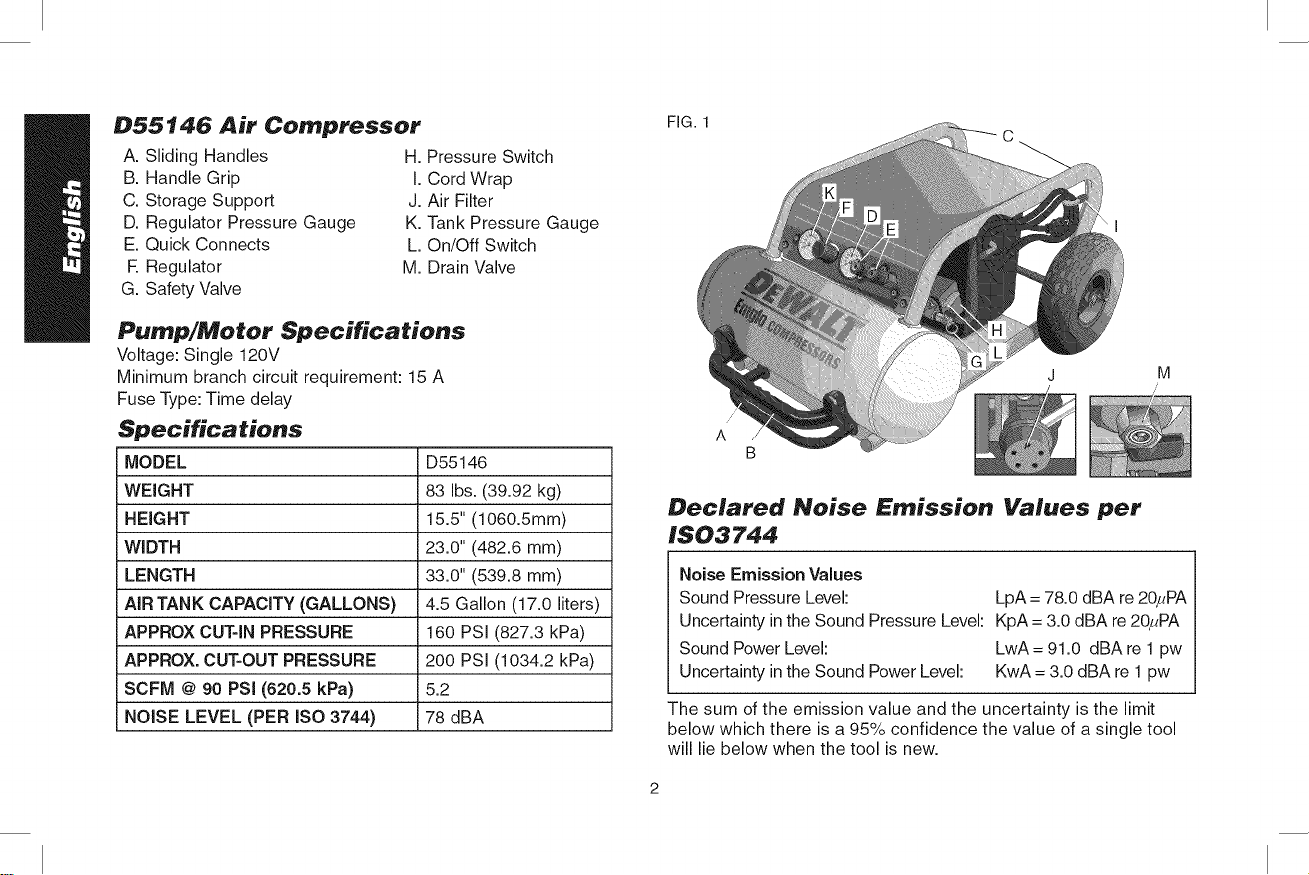
D55146 Air Compressor
A. Sliding Handles
B. Handle Grip
C. Storage Support
D. Regulator Pressure Gauge
E. Quick Connects
R Regulator
G. Safety Valve
H. Pressure Switch
I. Cord Wrap
J. Air Filter
K. Tank Pressure Gauge
L. On/Off Switch
M. Drain Valve
Pump/Motor Specifications
Voltage: Single 120V
Minimum branch circuit requirement: 15 A
Fuse Type: Time delay
Specifications
MODEL D55146
WEIGHT 83 Ibs. (39.92 kg)
HEIGHT 15.5" (1060.5mm)
WIDTH 23.0" (482.6 mm)
LENGTH 33.0" (539.8 mm)
AIR TANK CAPACITY (GALLONS) 4.5 Gallon (17.0 liters)
APPROX CUT-IN PRESSURE 160 PSI (827.3 kPa)
APPROX. CUT-OUT PRESSURE 200 PSI (1034.2 kPa)
SCFM @ 90 PSi (620.5 kPa) 5.2
NOISE LEVEL (PER ISO 3744) 78 dBA
M
/
Declared Noise Emission Values per
IS03744
Noise Emission Values
Sound Pressure Level: LpA = 78.0 dBA re 20FPA
Uncertainty in the Sound Pressure Level: KpA = 3.0 dBA re 20FPA
Sound Power Level: LwA = 91.0 dBA re 1pw
Uncertainty in the Sound Power Level: KwA = 3.0 dBA re 1 pw
The sum of the emission value and the uncertainty is the limit
below which there is a 95% confidence the value of a single tool
will lie below when the tool is new.
Page 3
Definitions: Safety Guidelines
The definitions below describe the level of severity
for each signal word. Please read the manual and
pay attention to these symbols.
_,DANGER: Indicates an imminently hazardous
situation which, if not avoided, will result in death
or serious injury.
AWARNING: Indicates a potentially hazardous
situation which, if not avoided, could result in death
or serious injury.
ACAUTION: Indicates a potentially hazardous
situation which, if not avoided, may result in minor
or moderate injury.
CAUTION: Used without the safety alert symbol
indicates a potentially hazardous situation which, if
not avoided, may result in property damage.
IF YOU HAVE ANY QUESTIONS OR COMMENTS ABOUT
THIS OR ANY DEWALT TOOL, CALL US TOLL FREE AT:
1=800=4=DEWALT(1-800-433=9258)
Important Safety Instructions
WARNING: Do not operate this unit until you read and understand
this instruction manual for safety, operation and maintenance
instructions.
AWARNING: Some dust created by power sanding, sawing, grind-
ing, drilling, and other construction activities contains chemicals
known to the State of California tocause cancer, birth defects or other
reproductive harm. Some example of these chemicals are:
* lead from lead-based paints
* crystalline silica from bricks and cement and other masonry
products
* arsenic and chromium from chemically-treated lumber
Your risk from these exposures varies, depending on how often
you do this type of work. To reduce your exposure to these chemi-
cals: work in a weft ventilated area, and work with approved safety
equipment, always wear OSHA/MSHA/NIOSH approved, properly
fitting face mask or respirator when using such tools.
When using air tools, basic safety precautions should always be fol-
lowed to reduce the risk of of personal injury,
i_,WARNING: This product contains chemicals, including lead, known
to the State of California to cause cancer, and birth defects or other
reproductive harm. Wash hands after handling.
SAVE THESE INSTRUCTION
_&DANGER: RISK OF EXPLOSION OR FIRE
WHAT CAN HAPPEN HOWTO PREVENT IT
Itis n0ima! f0r electdca! ,Always Operate the C0mpreSi
contacts within the motor s0r in a well Ventilated area
and pressure switch t0 free 0f combUStible materials;
spark: gasoline, or solvent vapors,
If electrical sparks from
compressor come into con-
tact with flammable vapors,
they may ignite, causing fire
or explosion.
• Ifspraying flammable materi-
als, locate compressor at
least 20 feet (6.1 m) away
from spray area. An addi-
tional length of hose may be
required.
• Store flammable materials in
a secure location away from
compressor.
Page 4
, Restrictinganyofthecom- • Neverplaceobjectsagainst
pressorventilationopenings orontopofcompressor
willcauseseriousoverheat- pump.
ingandcouldcausefire. , Operate compressor in
an open area at least 12"
(30.5 cm) away from any
,wallor obstruction that would
restrict the flow of fresh air to
the ventilation openings.
- Operate compressor in a
clean, dry well ventilated area.
Do not operate unit indoors or
in any confined area.
• Unattended operation of
this product could result in
personal injury or property
damage. To reduce the risk
of fire. do not allow the
compressor to operate unat-
tended.
• Always remain in attendance
with the producl when it is
operating.
• Always turn off and unplug
unit when mot in use.
ADANGER: RISK TO BREATHING (ASPHYXIATION)
WHAT CAN HAPPEN HOWTO PREVENTIT
= The compressed air directly , Air obtained directly from the
from your compressor is not compressor should never
safe for breathing. The air be used to supply air for
stream may contain carbon human consumption, in order
monoxide, toxic vapors, to use air produced bythis
or solid particles from the compressor for breathing,
air tank. Breathing these suitable filters and in-line
contaminant's can cause safety equipment must be
serious Injury or death, properly installed. In-line
filters and safety equipment
used in conjunction with the
compressor must be capable
of treating air to all applicable
local and federal codes prior to
human consumption
Sprayed materials such as
paint, paint solvents, paint
remover, insecticides, weed
killers, may contain harmful
vapors and poisons.
Work in an area with good
cross ventilation. Read and
follow the safety instructions
provided on the label or safety
data sheets for the materials
you are spraying. Always use
certified safety equipment:
OSHA/MSHA/NIOSH
respiratory protection designed
for use with your specific
application.
Page 5
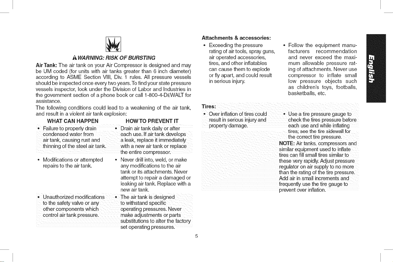
J_WARNING: RiSK OF BURSTING
Air Tank: The air tank on your Air Compressor is designed and may
be UM coded (for units with air tanks greater than 6 inch diameter)
according to ASME Section VIII, Div. 1 rules. All pressure vessels
should be inspected once every two years.To find your state pressure
vessels inspector, look under the Division of Labor and Industries in
the government section of a phone book or call 1-800-4-DEWALT for
assistance.
The following conditions could lead to a weakening of the air tank.
and result in a violent air tank explosion:
WHAT CAN HAPPEN HOWTO PREVENT iT
• Failureto properly drain • Drain air tank daily or after
condensed water from each use. If air tank develops
air tank. causing rust and a leak. replace it immediately
thinning of the steel air tank. with a new air tank or replace
the entire compressor.
• Modifications or attempted - Never drill into. weld. or make
repairs to the air tank. any modifications to the air
tank or itsattachments. Never
attempt to repair a damaged or
eaking air tank. Replace with a
new air tank.
Unauthorized modifications • The airtank is designed
to the safety valve or any to withstand specific
other components which operating pressures. Never
control air tank pressure, make adjustments or parts
substitutions to alter the factory
set operating pressures.
Attachments & accessories:
Exceeding the pressure
rating of air tools, spray guns,
air operated accessories,
tires, and other inflatables
can cause them to explode
or fly apart, and could result
in serious injury.
Tires:
Over inflation of tires could - Use atire pressure gauge to
result in serious injury and check the tires pressure before
property damage, each use and while inflating
Follow the equipment manu-
facturers recommendation
and never exceed the maxi-
mum allowable pressure rat-
ing of attachments. Never use
compressor to inflate small
low pressure objects such
as children's toys, footballs,
basketballs, etc.
tires: see thetire sidewall for
the correct tire oressure.
NOTE: Air tanks, compressors and
similar equipment used to inflate
tires can fill small tires similar to
these very rapidly.Adjust pressure
regulator on air supply to no more
than the rating ofthe tire pressure.
Add air in small increments and
frequently use the tire gauge to
prevent over inflation.
Page 6
,&WARNING: RISK OF ELECTRICAL SHOCK
WHAT CAN HAPPEN
• Your air compressor is
powered by electricity.
Like any other electrically
powered device. If it is not
used properly it may cause
electric shock.
• Repairs attempted by
unqualified personnel can repairs required on this
result in serious injury or product should be performed
death by electrocution, by a DEWALT factory
• Electrical Grounding:
Failure to provide adequate
grounding to this product
could result in serious injury
or death from electrocution.
See Grounding
Instructions under
Installation.
HOWTO PREVENT IT
• Never operate the
compressor outdoors when it
is raining or in wet conditions.
- Never operate compressor
with protective covers
removed or damaged.
Any electrical wiring or
service center or a DEWALT
authorized service center in
accordance with national and
local electrical codes.
Make certain that the
electrical circuit to which the
compressor is connected
provides proper electrical
grounding, correct voltage
and adequate fuse protection.
,&WARNING: RISK FROM FLYING OBJECTS
WHAT CAN HAPPEN
The compressed air stream •
can cause soft tissue
damage to exposed skin and
can propel dirt, chips, loose
particles, and small objects
at high speed, resulting in
property damage or personal
injury.
Always wear certified safety
equipment: ANSI Z87.1 eye
protection (CAN/CSA Z94.3)
with side shields when using
the compressor.
Never point any nozzle or
sprayer toward any part of
the body orat other people or
animals.
o Always turn the compressor off
and bleed pressure from the
air hose and air tank before
attempting maintenance.
attaching tools or accessories.
HOWTO PREVENTIT
Page 7
•_WARNING: RiSK OF NOT SURFACES
WHAT CAN HAPPEN HOW TO PREVENT iT
• Touching exposed metal
such as the compressor
head, engine head, engine
exhaust or outlet tubes, can
result inserious burns.
A WARNING: RISK FROM MOVING PARTS
WHAT CAN HAPPEN HOWTO PREVENTJT
Moving parts such as the _ Never operate the compressor
pulley, flywheel, and belt can with guards or covers which
cause serious injury if they are damaged or removed.
come into contact with you or • Keep your hair, clothing, and
your clothing, gloves away from moving
• Never touch any exposed
metal parts on compressor
during or immediately after
operation. Compressor will
remain hot for several minutes
after operation.
• Do not reach around
protective shrouds or attempt
maintenance until unit has
been allowed to cool.
parts. Loose clothes, jewelry,
or long hair can be caught in
moving parts.
• Air vents may cover moving
parts and should be avoided
as well.
• Attempting to operate
compressor with damaged or
missing parts or attempting
to repair compressor with
protective shrouds removed
can expose you to moving
parts and can result in
serious injury.
J_WARNING: RiSK OF UNSAFE OPERATION
WHAT CAN HAPPEN HOWTO PREVENT iT
Unsafe operation of your air • Review and understand all
compressor could lead to seri- instructions and warnings in
ous injury or death 1oyou or this manual.
others. , Become familiar with the
• Any repairs required on this
product should be performed
by a DEWALT factory
service center or a DEWALT
authorized service center.
operation and controls of the
air compressor.
• Keep operating area clear
of all persons, pets, and
obstacles.
• Keep children away from the
air compressor at all times.
- Do not operate the product
when fatigued or under the
influence of alcohol or drugs.
Stay alert at all times.
- Never defeat the salety fea-
tures of this product.
Page 8
,Do notoperatemachinewith
missing,broken,Orunauthoi
rizedparts.
,,Never Stand Onthe
compressor.
,&CAUTION: RISK FROM NOISE
WHAT CAN HAPPEN
• Under some conditions and
duration of use, noise from
this product may contribute
to hearing loss.
HOWTO PREVENT IT
• Always wear certified safety
equipment: ANSI $12.6
($3.19) hearing protection.
`& WARNING: RiSK OF FALLING
WHAT CAN HAPPEN
A portable compressor
can fall from a table,
workbench, or roof causing
damage to the compressor
and could result in serious
injury or death to the
operator.
`& WARNING: RISK OF INJURY FROM LIFTING
WHAT CAN HAPPEN HOWTO PREVENT IT
*serious injurycan result
from attempting tolift too heavyto be lifted byone
heavy an object, person. Qbtain assistance
HOWTO PREVENT IT
• Always operate compressor
in a stable secure position to
prevent accidental movement
of the unit. Never operate
compressor on a roof or
other elevated position. Use
additional air hose to reach
high locations.
from others before lifting.
SAVE THESE INSTRUCTIONS
FOR FUTURE USE
Page 9
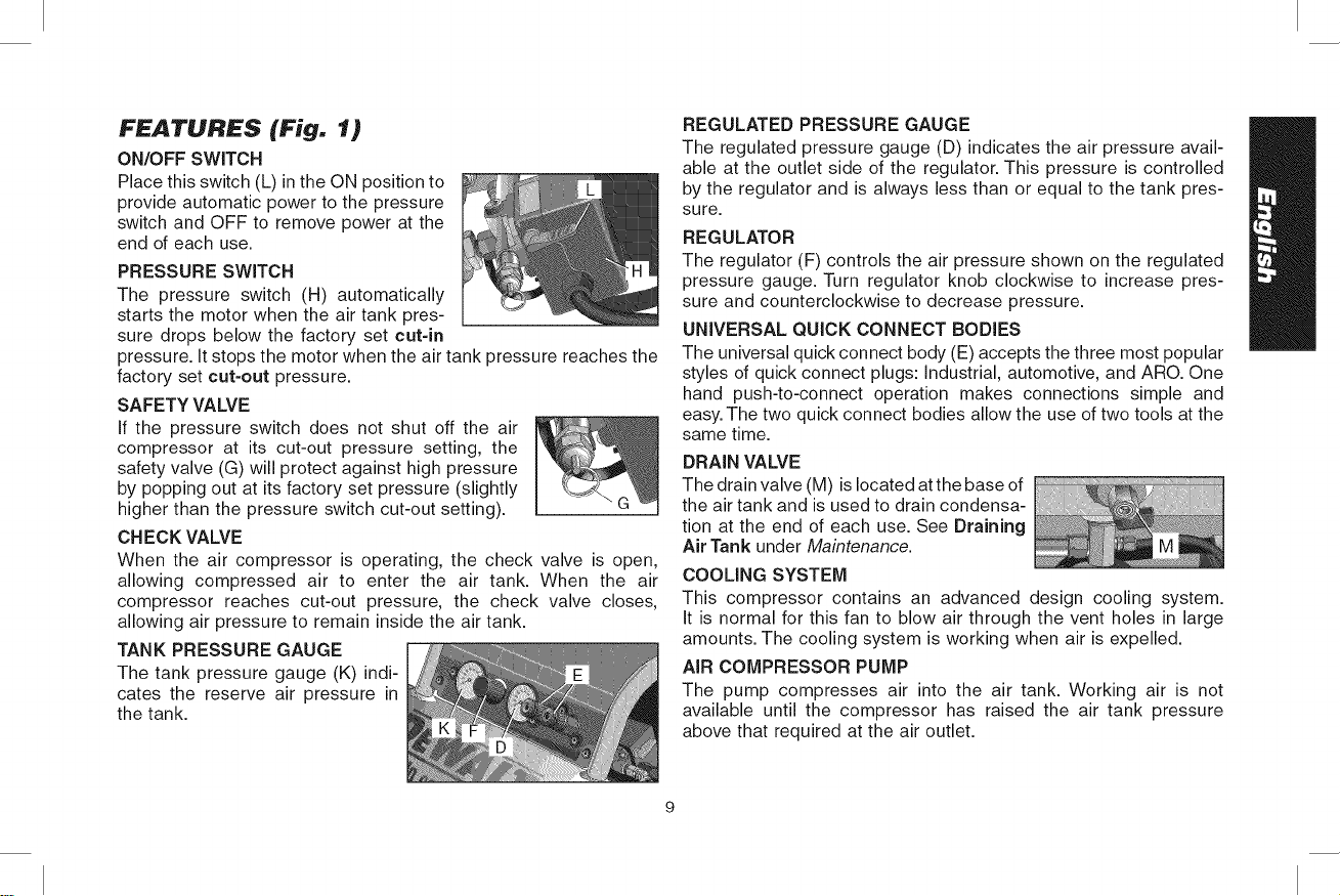
FEATURES (Fig. 1)
ON/OFF SWITCH
Place this switch (L) in the ON position to
provide automatic power to the pressure
switch and OFF to remove power at the
end of each use.
PRESSURE SWITCH
The pressure switch (H) automatically
starts the motor when the air tank pres-
sure drops below the factory set cut-in
pressure. It stops the motor when the air tank pressure reaches the
factory set cut-out pressure.
SAFETY VALVE
If the pressure switch does not shut off the air
compressor at its cut-out pressure setting, the
safety valve (G) will protect against high pressure
by popping out at its factory set pressure (slightly
higher than the pressure switch cut-out setting).
CHECK VALVE
When the air compressor is operating, the check valve is open,
allowing compressed air to enter the air tank. When the air
compressor reaches cut-out pressure, the check valve closes,
allowing air pressure to remain inside the air tank.
TANK PRESSURE GAUGE
The tank pressure gauge (K) indi-
cates the reserve air pressure in
the tank.
REGULATED PRESSURE GAUGE
The regulated pressure gauge (D) indicates the air pressure avail-
able at the outlet side of the regulator. This pressure is controlled
by the regulator and is always less than or equal to the tank pres-
sure.
REGULATOR
The regulator (F) controls the air pressure shown on the regulated
pressure gauge. Turn regulator knob clockwise to increase pres-
sure and counterclockwise to decrease pressure.
UNIVERSAL QUICK CONNECT BODIES
The universal quick connect body (E) accepts the three most popular
styles of quick connect plugs: Industrial, automotive, and ARO. One
hand push-to-connect operation makes connections simple and
easy. The two quick connect bodies allow the use of two tools at the
same time.
DRAIN VALVE
The drain valve (M) is located atthe base of
the air tank and is used to drain condensa-
tion at the end of each use. See Draining
Air Tank under Maintenance.
COOLING SYSTEM
This compressor contains an advanced design cooling system.
It is normal for this fan to blow air through the vent holes in large
amounts. The cooling system is working when air is expelled.
AIR COMPRESSOR PUMP
The pump compresses air into the air tank. Working air is not
available until the compressor has raised the air tank pressure
above that required at the air outlet.
Page 10
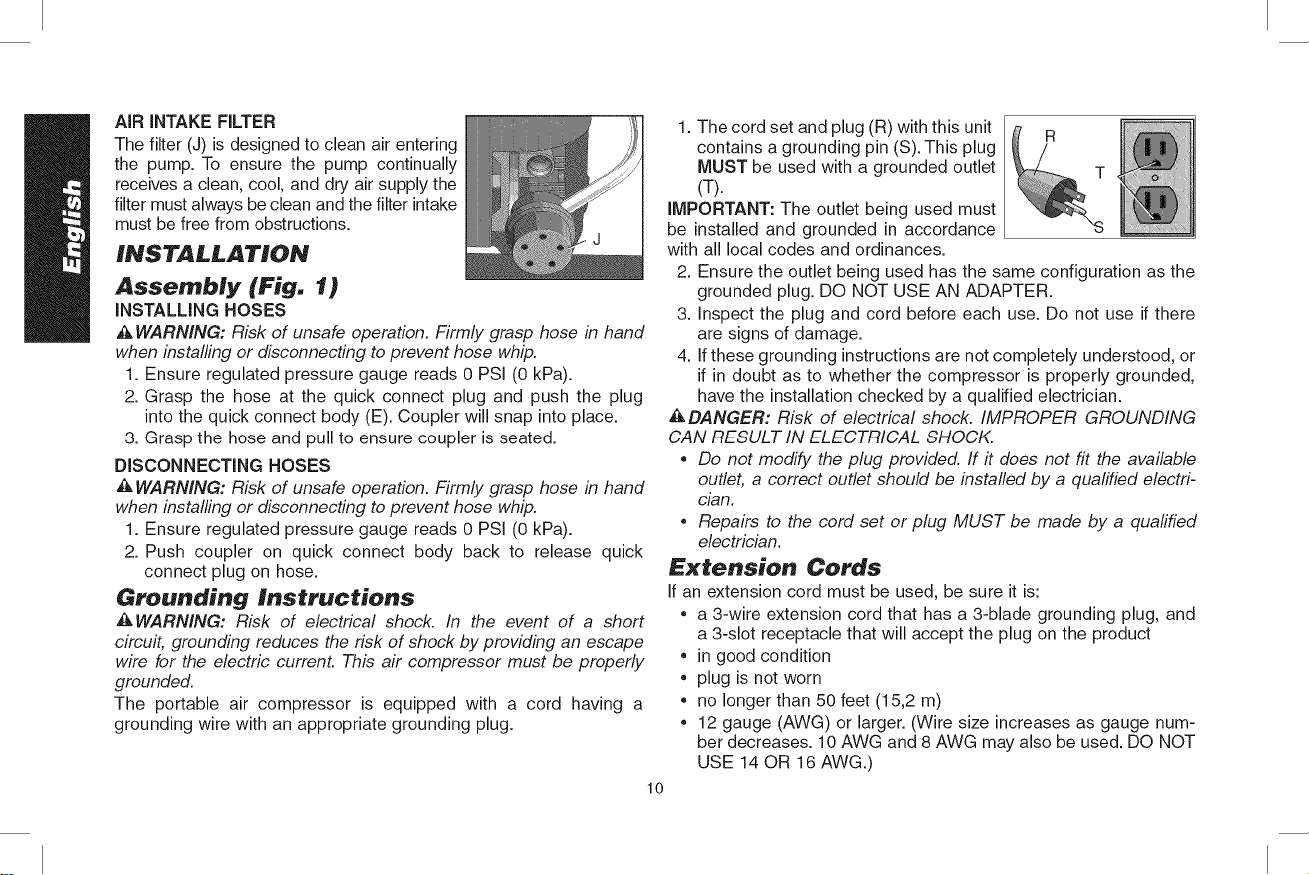
AIRINTAKEFILTER
Thefilter(J)isdesignedtocleanairentering
thepump.Toensure the pump continually
receives a clean, cool, and dry air supply the
filter must always be clean and the filter intake
must be free from obstructions.
INSTALLATION
Assembly (Fig. 1)
INSTALLING HOSES
_kWARNING: Risk of unsafe operation. Firmly grasp hose in hand
when installing or disconnecting to prevent hose whip.
1. Ensure regulated pressure gauge reads 0 PSi (0 kPa).
2. Grasp the hose at the quick connect plug and push the plug
into the quick connect body (E). Coupler will snap into place.
3. Grasp the hose and pull to ensure coupler is seated.
DISCONNECTING HOSES
,_ WARNING: Risk of unsafe operation. Firmly grasp hose in hand
when installing or disconnecting to prevent hose whip.
1. Ensure regulated pressure gauge reads 0 PSI (0 kPa).
2. Push coupler on quick connect body back to release quick
connect plug on hose.
Groundin9 Instructions
_WARNING: Risk of electrical shock. In the event of a short
circuit, grounding reduces the risk of shock by providing an escape
wire for the electric current. This air compressor must be properly
grounded.
The portable air compressor is equipped with a cord having a
grounding wire with an appropriate grounding plug.
1. The cord set and plug (R) with this unit
contains a grounding pin (S). This plug
MUST be used with a grounded outlet
(T).
IMPORTANT: The outlet being used must
be installed and grounded in accordance
with all local codes and ordinances.
2. Ensure the outlet being used has the same configuration as the
grounded plug. DO NOT USE AN ADAPTER.
3. Inspect the plug and cord before each use. Do not use if there
are signs of damage.
4. If these grounding instructions are not completely understood, or
if in doubt as to whether the compressor is properly grounded,
have the installation checked by a qualified electrician.
DANGER: Risk of electrical shock. IMPROPER GROUNDING
CAN RESULT IN ELECTRICAL SHOCK.
• Do not modify the plug provided, ff it does not fit the available
outlet, a correct outlet should be installed by a qualified electri-
cian.
• Repairs to the cord set or plug MUST be made by a quafified
electrician.
R
Extension Cords
If an extension cord must be used, be sure it is:
• a 3-wire extension cord that has a 3-blade grounding plug, and
a 3-slot receptacle that will accept the plug on the product
• in good condition
• plug is not worn
• no longer than 50 feet (15,2 m)
• 12 gauge (AWG) or larger. (Wire size increases as gauge num-
ber decreases. 10 AWG and 8 AWG may also be used. DO NOT
USE 14 OR 16 AWG.)
lO
Page 11
CAUTION: The use of an undersized extension cord wifl cause volt-
age to drop resulting in power loss to the motor and overheating.
Instead of using an extension cord, increase the working reach of
the air hose by attaching another length of hose to its end. Attach
additional lengths of hose as needed. Always use a minimum 3/8"
(9.5 mm) or greater air hose rated at 300 PSI.
Voltage and Circuit Protection
Refer to the Voltage and Minimum Branch Circuit Requirements
under Specifications.
&CAUTION: Certain air compressors can be operated on a
15 amp circuit ff the following conditions are met.
• Voltage supply to circuit must comply with the National Electrical
Code.
• Circuit is not used to supply any other electrical needs.
• Extension cords comply with specifications.
• Circuit is equipped with a 15 amp circuit breaker or 15 amp
time delay fuse. NOTE: If compressor is connected to a circuit
protected by fuses, use only time delay fuses. Time delay fuses
should be marked "D" in Canada and "T" in the U.S.
If any of the above conditions cannot be met, or if operation of the
compressor repeatedly causes interruption of the power, it may be
necessary to operate it from a 20 amp circuit. It is not necessary
to change the cord set.
Compatibility
Air tools and accessories that are run off the compressor must be
compatible with petroleum-based products. If you suspect that a
material is not compatible with petroleum products, an air line filter
for removal of moisture and oil vapor in compressed air is required.
NOTE: Always use an air line filter to remove moisture and oil vapor
when spraying paint.
Location
Place the air compressor in a clean, dry and well ventilated area
at least 12" (30.5 cm) away from the wall or other obstructions that
will interfere with the flow of air. Keep the compressor away from
areas that have dirt and/or volatile fumes in the atmosphere. These
impurities may clog the intake filter and valves, causing inefficient
operation.
_kWARNING: The air compressor pump and shroud are designed
to allow for proper cooling. The ventilation openings on the com-
pressor are necessary to maintain proper operating temperature.
Do not place rags or other containers on or near these openings.
Place the air compressor on a flat surface resting on the wheels
and rubber foot.
ELECTRICAL
Refer to all safety instructions before using unit. Observe extension
cord safety instructions, if necessary. Always move the On/Off
switch (L) to the OFF position before removing the plug from the
outlet.
Transporting
When transporting the compressor in a vehicle, trailer, etc. ensure
that the air tank is drained and the unit is secured and placed on a
flat horizontal surface. Use care when driving so to avoid tipping the
unit over in the vehicle. Damage can occur to the unit or surrounding
items if unit is tipped.
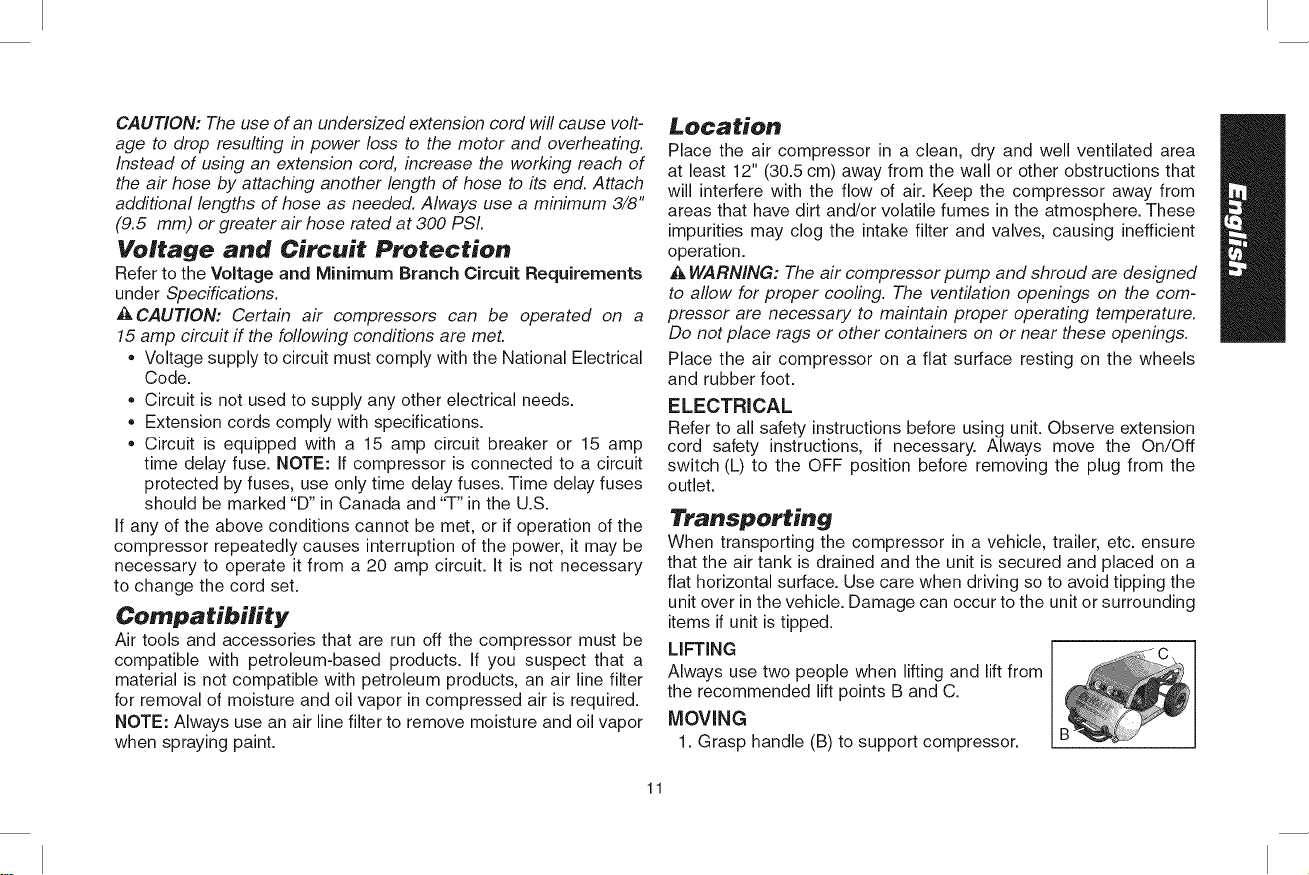
LIFTING
Always use two people when lifting and lift from
the recommended lift points B and C.
MOVING
1. Grasp handle (B) to support compressor.
11
Page 12
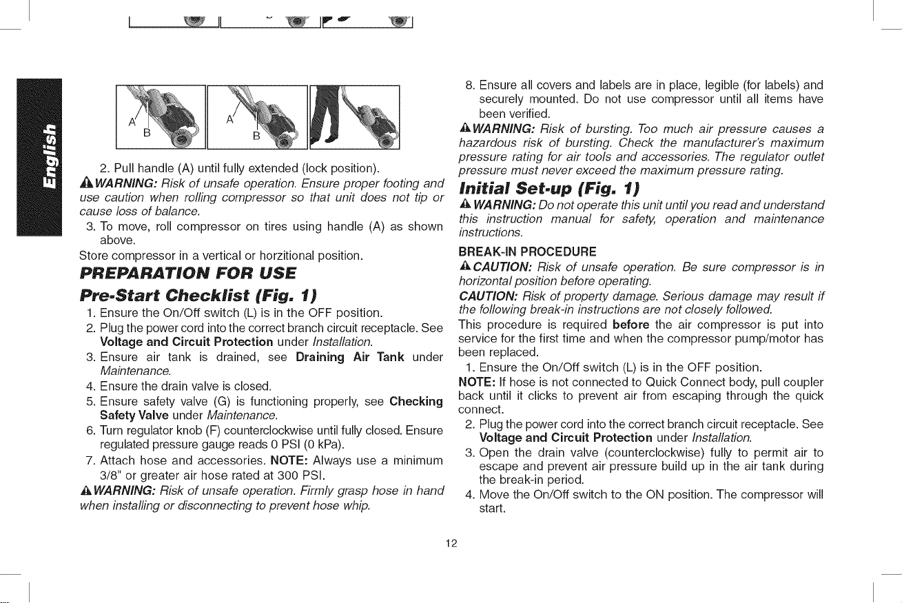
2. Pull handle (A) until fully extended (lock position).
WARNING: Risk of unsafe operation. Ensure proper footing and
use caution when rolling compressor so that unit does not tip or
cause loss of balance.
3. To move, roll compressor on tires using handle (A) as shown
above.
Store compressor in a vertical or horzitional position.
PREPARATION FOR USE
Pre-Start Checklist (Fig. 1)
1. Ensure the On/Off switch (L) is in the OFF position.
2. Plug the power cord into the correct branch circuit receptacle. See
Voltage and Circuit Protection under Installation.
3. Ensure air tank is drained, see Draining Air Tank under
Maintenance.
4. Ensure the drain valve is closed.
5. Ensure safety valve (G) is functioning properly, see Checking
Safety Valve under Maintenance.
6. Turn regulator knob (F) counterclockwise until fully closed. Ensure
regulated pressure gauge reads 0 PSI (0 kPa).
7. Attach hose and accessories. NOTE: Always use a minimum
3/8" or greater air hose rated at 300 PSI.
WARNING: Risk of unsafe operation. Firmly grasp hose in hand
when installing or disconnecting to prevent hose whip.
8. Ensure all covers and labels are in place, legible (for labels) and
securely mounted. Do not use compressor until all items have
been verified.
_&WARNING: Risk of bursting. Too much air pressure causes a
hazardous risk of bursting. Check the manufacturer's maximum
pressure rating for air tools and accessories. The regulator outlet
pressure must never exceed the maximum pressure rating.
Initial Set.up (Fig. 1)
WARNING: Do not operate this unit until you read and understand
this instruction manual for safety, operation and maintenance
instructions.
BREAK-IN PROCEDURE
CAUTION: Risk of unsafe operation. Be sure compressor is in
horizontal position before operating.
CAUTION: Risk of property damage. Serious damage may result if
the following break-in instructions are not closely followed.
This procedure is required before the air compressor is put into
service for the first time and when the compressor pump/motor has
been replaced.
1. Ensure the On/Off switch (L) is in the OFF position.
NOTE: If hose is not connected to Quick Connect body, pull coupler
back until it clicks to prevent air from escaping through the quick
connect.
2. Plug the power cord into the correct branch circuit receptacle. See
Voltage and Circuit Protection under Installation.
3. Open the drain valve (counterclockwise) fully to permit air to
escape and prevent air pressure build up in the air tank during
the break-in period.
4. Move the On/Off switch to the ON position. The compressor will
start.
12
Page 13
5. Run the compressor for 15 minutes.
6. After 15 minutes, close the drain valve by turning clockwise.
The tank will fill to cut-out pressure and the motor will stop.
7. Compressed air will be available until it is used or bled off.
OPERATING PROCEDURES
Start-up (Fig. 1)
1. Follow Pre-Start Checklist under Preparation for Use.
CAUTION: Risk of unsafe operation. Do not operate in upright
position. Upright position is for storage only.
2. Move the On/Off switch to the ON position and allow tank pres-
sure to build. Motor will stop when tank pressure reaches
cut-out pressure.
CAUTION: Risk of unsafe operation. Compressed air from the
unit may contain water condensation and oil mist. Do not spray unfil-
tered air at an item that could be damaged by moisture. Some air
operated tools or devices may require filtered air. Read the instruc-
tions for the air tool or device.
3. Adjust regulator (F) to desired setting. See Regulator under
Features.
Shut-down (Fig. 1)
1. Move On/Off switch (L) to the OFF position. NOTE: If finished
using compressor, follow Steps 2 - 6.
2. Turn regulator knob (F) counterclockwise until fully closed. Ensure
regulated pressure gauge reads 0 PSI (0 kPa).
3. Remove hose and accessory.
4. Drain the air tank, see Draining Air Tank under Maintenance.
Ensure air tank pressure gauge reads 0 PSI (0 kPa).
_kWARNING: Risk of bursting. Drain air tank daily. Water will con-
dense in air tank. ff not drained, water will corrode and weaken the
air tank causing a risk of air tank rupture.
5. Allow the compressor to cool down.
6. Wipe air compressor clean and store in a safe, non-freezing
area.
_kCAUTION: Risk of unsafe operation. Do not operate in upright
position. Upright position is for storage only.
MAINTENANCE
The following procedures must be followed when maintenance or
service is performed on the air compressor.
1. Ensure On/Off switch is in the OFF position.
2. Remove air compressor plug from outlet.
3. Drain air tank.
4. Allow air compressor to cool down before starting service.
NOTE: All compressed air systems contain maintenance parts (e.g.,
oil, filters, separators) that are periodically replaced. These used parts
may contain substances that are regulated and must be disposed of in
accordance with local, state, and federal laws and regulations.
NOTE: Take note of the positions and locations of parts during
disassembly to make reassembly easier.
NOTE: Any service operations not included in this section should
be performed by a DEWALT factory service center or a DEWALT
authorized service center.
13
Page 14
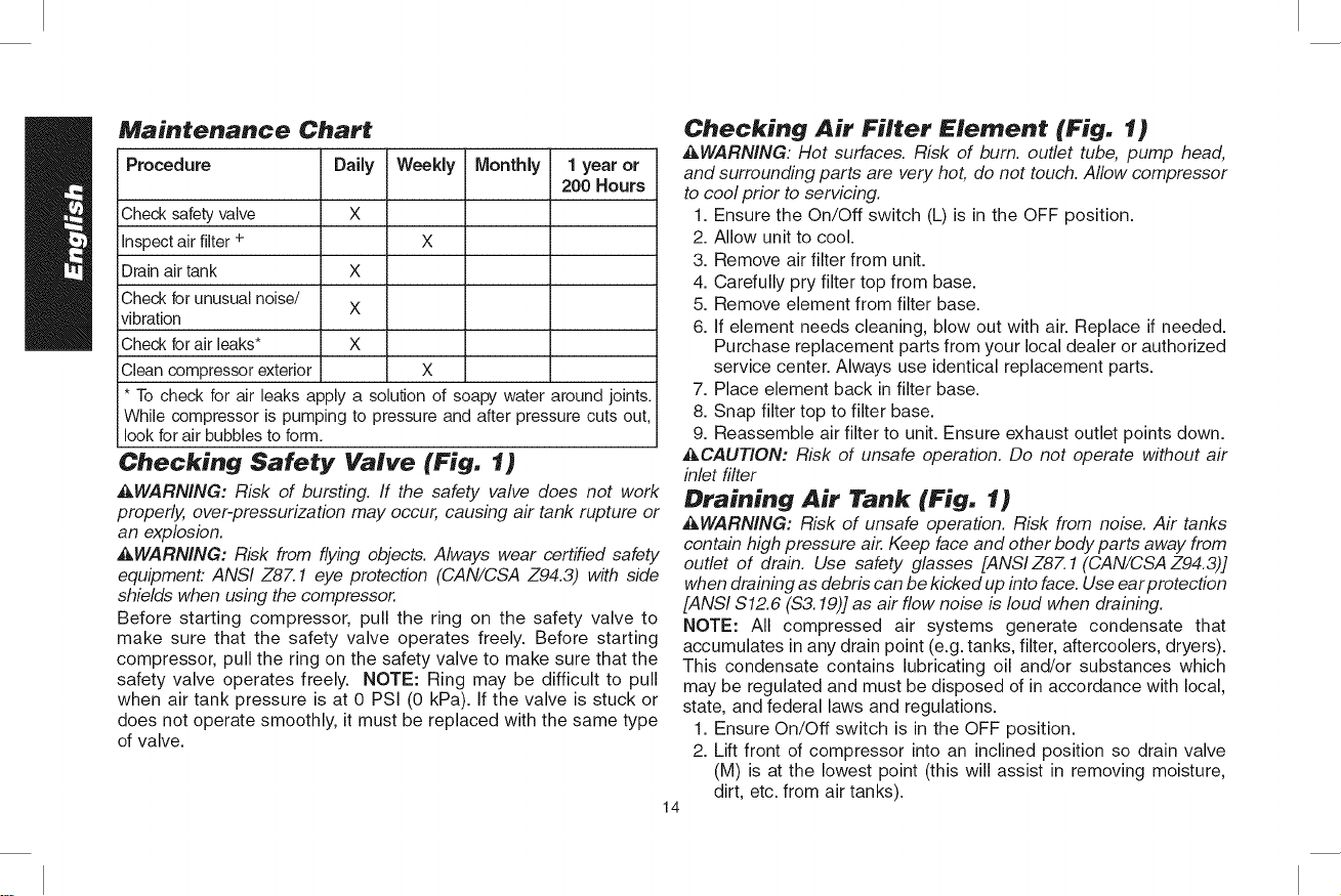
Maintenance Chart
Procedure Daily Weekly Monthly 1year or
Check safetyvalve
inspectair filter +
Drain air tank X
Check for unusual noise/
vibration
Check for air leaks* X
Clean compressor exterior X
* To check for air leaks apply a solution of soapy water around joints.
While compressor is pumping to pressure and after pressure cuts out,
look forair bubbles to form.
X
X
200 Hours
Checking Safety Valve (Fig. 1)
_,WARNING: Risk of bursting. If the safety valve does not work
properly, over-pressurization may occur, causing air tank rupture or
an explosion.
AWARNING: Risk from flying objects. Always wear certified safety
equipment: ANSI Z87.1 eye protection (CAN/CSA Z94.3) with side
shields when using the compressor.
Before starting compressor, pull the ring on the safety valve to
make sure that the safety valve operates freely. Before starting
compressor, pull the ring on the safety valve to make sure that the
safety valve operates freely. NOTE: Ring may be difficult to pull
when air tank pressure is at 0 PSi (0 kPa). If the valve is stuck or
does not operate smoothly, it must be replaced with the same type
of valve.
Checking Air Filter Element (Fig. 1)
_,WARNING: Hot surfaces. Risk of burn. outlet tube, pump head,
and surrounding parts are very hot, do not touch. Allow compressor
to cool prior to servicing.
1. Ensure the On/Off switch (L) is in the OFF position.
2. Allow unit to cool.
3. Remove air filter from unit.
4. Carefully pry filter top from base.
5. Remove element from filter base.
6. If element needs cleaning, blow out with air. Replace if needed.
Purchase replacement parts from your local dealer or authorized
service center. Always use identical replacement parts.
7. Place element back in filter base.
8. Snap filter top to filter base.
9. Reassemble air filter to unit. Ensure exhaust outlet points down.
_,CAUTION: Risk of unsafe operation. Do not operate without air
inlet filter
Draining Air Tank (Fig. 1)
_WARNING: Risk of unsafe operation. Risk from noise. Air tanks
contain high pressure air. Keep face and other body parts away from
outlet of drain. Use safety glasses [ANSI Z87.1 (CAN/CSA Z94.3)]
when draining as debris can be kicked up into face. Use ear protection
[ANSI $12.6 ($3.19)] as air flow noise is loud when draining.
NOTE: All compressed air systems generate condensate that
accumulates in any drain point (e.g. tanks, filter, aftercoolers, dryers).
This condensate contains lubricating oil and/or substances which
may be regulated and must be disposed of in accordance with local,
state, and federal laws and regulations.
1. Ensure On/Off switch is in the OFF position.
2. Lift front of compressor into an inclined position so drain valve
(M) is at the lowest point (this will assist in removing moisture,
dirt, etc. from air tanks).
14
Page 15
3.Placea suitablecontainerunderthedrainvalveto catch
discharge.
4.Graspknobondrainvalve.
5.Slowlyrotateknobtograduallybleedairfromairtank.
_kWARNING: Risk of bursting. Drain air tank daily. Water will con-
dense in air tank. If not drained, water will corrode and weaken the
air tank causing a risk of air tank rupture.
CAUTION: Risk of property damage. Drain water from air tank may
contain oil and rust, which can cause stains.
6. When air tank pressure gauge reads 10 PSI (68,9 kPa), rotate
valve to the fully open position.
7. Close drain valve when finished.
ACCESSORIES
_WARNING: The use of any other accessory not recommended for
use with this tool could be hazardous. Use only accessories rated
equal to or higher than the rating of the air compressor.
Recommended accessories for use with your tool are available
for purchase from your local dealer or authorized service center.
If you need assistance in locating any accessory for your tool,
please contact DEWALT Industrial Tool Co., 701 East Joppa Road,
Baltimore, MD 21286, call 1-800-4-DEWALT (1-800-433-9258) or visit
our website www.dewalt.com.
SERVICE INFORMATION
Please have the following information available for all service calls:
Model Number Serial Number
Date and Place of Purchase
Repairs
To assure product SAFETY and RELIABILITY, repairs, maintenance
and adjustment should be performed by a DEWALT factory service
center, a DEWALT authorized service center or other qualified
service personnel. Always use identical replacement parts.
Full One Year Warranty
DEWALT heavy duty industrial tools are warranted for one year from
date of purchase. We will repair, without charge, any defects due
to faulty materials or workmanship. For warranty repair information,
call 1-800-4-DEWALT. This warranty does not apply to accessories
or damage caused where repairs have been made or attempted by
others. This warranty gives you specific legal rights and you may
have other rights which vary in certain states or provinces.
LATIN AMERICA: This warranty does not apply to products sold
in Latin America. For products sold in Latin America, see country
specific warranty information contained either in the packaging, call
the local company or see website for warranty information.
FREE WARNING LABEL REPLACEMENT: If your warning labels
become illegible or are missing, call 1-800-4-DEWALT for a free
replacement.
IX) NOT OPERfq E IN UPRIGH [ NO OPERE LA HERRAMIEN [A EN NE RAS FAIRE FONCTIONNER EN POSITION
POSITION. U PRIGH ["POSI]ION POSICION VERIICAL SO[() VERTICAL E, [A POSrflON VERTICALE ESI
IS FOR STORAGE ONLY. AL MACENE EN ES[A POSICION. RESERVEE AU STOC KAGE UNIQUEMEN L
15
Page 16
GLOSSARY
CFM: Cubic feet per minute.
SCFM: Standard cubic feet per minute; a unit of measure of air delivery.
PSi" Pounds per square inch; a unit of measure of pressure.
kPa (kilopascal): Metric pressure measurement. 1 kilopascal equal 1000 pascals.
Code Certification: Products that bear one or more of the following marks: UL, CUL, ETL, CETL, have been evaluated by OSHA
certified independent safety laboratories and meet the applicable Underwriters Laboratories Standards for Safety.
Cut-In Pressure: While the motor is off, air tank pressure drops when accessory is used. When the tank pressure drops to a certain low
level the motor will restart automatically. The low pressure at which the motor automatically restarts is called cut-in pressure.
Cut-Out Pressure: When an air compressor is turned on and begins to run, air pressure in the air tank begins to build. It builds to a
certain high pressure before the motor automatically shuts off, protecting your air tank from pressure higher than its capacity. The high
pressure at which the motor shuts off is called cut-out pressure.
Branch Circuit: The circuit carrying electricity from electrical panel to outlet.
Duty Cycle: This air compressor pump is capable of running continuously. However, to prolong the life of your air compressor, it is
recommended that a 50%-75% average duty cycle be maintained; that is, the air compressor pump should not run more than 30-
45 minutes in any given hour.
16
Page 17
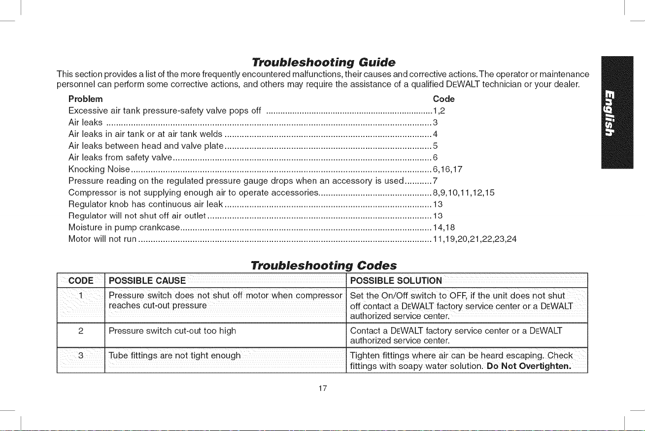
Troubleshooting Guide
This section provides a listofthe more frequently encountered malfunctions, their causes and corrective actions.The operator or maintenance
personnel can perform some corrective actions, and others may require the assistance of a qualified DEWALT technician or your dealer.
Problem Code
Excessive air tank pressure-safety valve pops off ...................................................................... 1,2
Air leaks .................................................................................................................................... 3
Air leaks in air tank or at air tank welds .................................................................................... 4
Air leaks between head and valve plate .................................................................................... 5
Air leaks from safety valve ......................................................................................................... 6
Knocking Noise .......................................................................................................................... 6,16,17
Pressure reading on the regulated pressure gauge drops when an accessory is used ........... 7
Compressor is not supplying enough air to operate accessories .............................................. 8,9,10,11,12,15
Regulator knob has continuous air leak .................................................................................... 13
Regulator will not shut off air outlet ........................................................................................... 13
Moisture in pump crankcase ...................................................................................................... 14,18
Motor will not run ....................................................................................................................... 11,19,20,21,22,23,24
Troubleshooting Codes
CODE POSSIBLE CAUSE 'POSSIBLE SOLUTION
' pressure switch does not shut off m0t0r when compressor Set the on/off Switch t0 OFF, if the unit doeS not shut
reaches cut_0ut pressure Off contact a DEWALTfact0iy service Ceniei or a DEWALT
! authorized service center.
2 Pressure switch cut-out too high Contact a DEWALT factory service center or a DEWALT
3 Tube fittingS are n0t tight enough Tighte_ fittings Where air can be heaid esCaPing. Check
: fittings with soapy water solution. Do Not Overtighten,
authorized service center.
17
Page 18
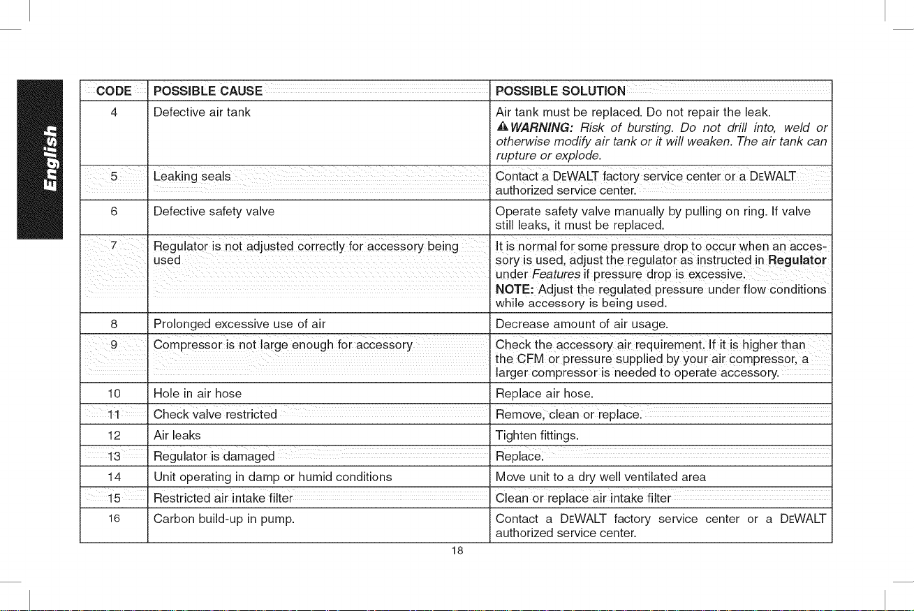
CODE POSSIBLE CAUSE POSSIBLE SOLUTION
4 Defective air tank Air tank must be replaced. Do not repair the leak.
_kWARNING: Risk of bursting. Do not drill into, weld or
otherwise modify air tank or it will weaken. The air tank can
rupture or explode.
i
5 Leaking seals Contact a DEWALT factory serv ce center or a DEWALT
J auth0rized service center.
6 Defective safety valve Operate safety valve manually by pulling on ring. If valve
still leaks, it must be replaced.
Reguiatei is not adjuSted Correct!y for acCesS0ry being It is norma! for some pressure drop t° occur when an aCoes_
used sory is used, adjust the regulator as instructed in Regu!ator
under Features if pressure droP is excessivei
NOTE: Adjust the regu ated pressure under f ow cond t 0ns
while accessory is being used.
8 Prolonged excessive use of air Decrease amount of air usage.
check the acCeSSorY air requiremenL if it is higher than
the CFM or pressure supplied by your air compressor, a
! larger compressor is needed to operate accessory.
10 Hole in air hose Replace air hose.
11 check valve restricted Remove; Clean or replacel
12 Air leaks Tighten fittings.
Reguiat0r is damaged
14 Unit operating in damp or humid conditions Move unit to a dry well ventilated area
15 'Restricted air intake filter ................................................................................................Clean or replace air intake filter
16 Carbon build-up in pump. Contact a DEWALT factory service center or a DEWALT
authorized service center.
18
Page 19
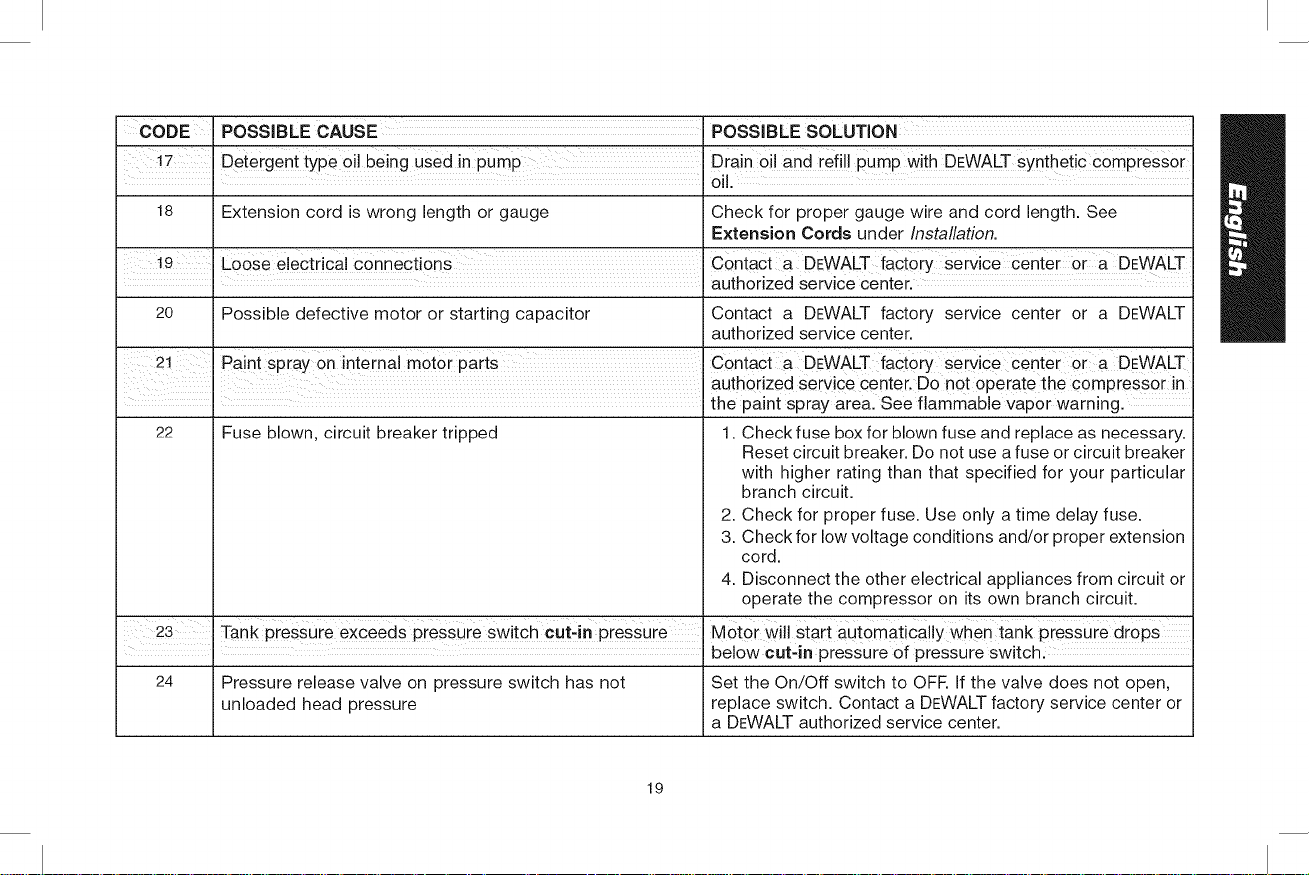
CODE
POSSIBLE CAUSE i POSSIBLE SOLUTION:
'Drain oiJ and refill pumP with DEWALT synthetic compressor
0il,
18 Extension cord is wrong length or gauge
Check for proper gauge wire and cord length. See
Extension Cords under Installation.
COntact a DEWALT factory service Center a DEWALT
authorized service center.
20 Possible defective motor or starting capacitor
Contact a DEWALT factory service center or a DEWALT
authorized service center.
21 Paint spiay 0n internal motor parts Contact a DEWALT faCt0rY Seivice Centei a DEWALT
I auth0rized Service Center. Do not operate the compressor in
• the paint spray area. See flammaMe vapor warning.
22 Fuse blown, circuit breaker tripped 1. Check fuse box for blown fuse and replace as necessary.
Reset circuit breaker. Do not use a fuse or circuit breaker
with higher rating than that specified for your particular
branch circuit.
2. Check for proper fuse. Use only a time delay fuse.
3. Check for low voltage conditions and/or proper extension
cord.
4. Disconnect the other electrical appliances from circuit or
operate the compressor on its own branch circuit.
I
23 Tank pressure exceeds pressure switch cut-in pressure
i
i Motor will start automatically when tank pressure drops
below cut-in pressure of pressure switch!
24 Pressure release valve on pressure switch has not
unloaded head pressure
Set the On/Off switch to OFE If the valve does not open,
replace switch. Contact a DEWALTfactory service center or
a DEWALT authorized service center.
19
Page 20

Cornpresseur d_air D55146
A. Poignees coulissantes
B. Prise ergonomique
C. Appui de rangement
D. R_gulateur de pression
E. Branchements rapides
R R6gulateur
G. Soupape de sOret6
Fiche technique de la pornpe/du rnoteur
Tension : monophas6, 120V
Exigence minimale du circuit de d6rivation : 15 A
Type de fusible : temporisation
Fiche technique
MODELE
POIDS
HAUTEUR
LARGEUR
LONGUEUR
CAPACIT# DU RI_SERVOIR D'AIR
(GALLONS)
PRESSION D'ENCLENCHEMENT
APPROX.
ENV. PRESSION DE DI_CLENCHEMENT
PCMS (SCFM) @ g0 PSI (620,5 kPa)
NIVEAU SONORE (SELON ISO 3744)
H. Manocontacteur
I. Rembobineur de cordon
d'alimentation
J. Filtre d'admission d'air
K. ManomEtre de r6servoir
h Interrupteur marche arr_t
M. Robinet de purge
D55146
i39,92 kg (83 Ibs.
i 1060,5mm (15,5 po)
i482,6 mm (23,0 po)
i539,8 mm (33,0)
i4,5 (17,0 liters)
i827,3 kPa (160 PSI)
i1034,2 kPa (200 PSI)
5,2
78 dBA
FIG. 1
/
A
Valeurs de r_rnission de bruits d_clar_es
ere conforrnit_ avec rlSO 3744
Valeur de r6mission de bruits
Niveau de pression acoustique :
Incertitude du niveau de
pression acoustique calcule :
Niveau de puissance acoustique :
Incertitude du niveau de puissance
acoustique :
La somme de la valeur de 1'6mission et de I'incertitude 6tablit la
limite sous laquelle la valeur pour un seul outil y sera inf6rieure et
ce, a 95 % de fiabilit6 statistique.
2O
LpA = 78,0 dBA re 20!_PA
KpA = 3,0 dBA re 20!_PA
LwA = 91,0 dBA re 1 pw
KwA = 3,0 dBA re 1 pw
M
/
Page 21

D_finitions : lignes directrices en
rnati_re de s_curit_
Les d_finitions ci-dessous d_crivent le niveau de gravit_ pour
chaque symbole. Veuillez lire le mode d'emploi et porter une atten-
tion particuli_re & ces symboles.
&DANGER: Indique une situation dangereuse imminente qui, si
elle n'est pas evit_e, causera la mort ou des blessures graves.
_AVERTISSEMENT : Indique une situation potentiellement dan-
gereuse quL si elle n'est pas evit_e, pourrait se solder par un
deces ou des blessures graves.
_MISE EN GARDE : Indique une situation potentiellement dan-
gereuse quL si die n'est pas evitee pourrait se solder par des
blessures mineures ou moder_es.
MISE EN GARDE : Utilise sans le symbole d'alerte a la s6cufit_,
indique une situation potentiellement dangereuse quL si die n'est
pas evitee pourrait se solder par des dommages a la propriet6.
POUR TOUTES QUESTIONS OU COMMENTAIRES
RELATIFS(VES) ,a, L:OUTIL OU ,_, PROPOS DE TOUT AUTRE
OUTIL DEWALT, COMPOSER SANS FRAIS LE : 1-800-4-DEWALT
(1-800-433-9258)
Directives de s_curit_ irnportantes
_AVERTISSEMENT : Ale pas utiliser cet appareil avant d'avoir lu
et compris le mode d'emploi ainsi que I'int6gralit6 des directives de
s6curit6, d'utilisation et d'entretien.
_AVERTISSEMENT : Nertaines poussieres produites par les travaux
de pongage, sciage, meulage, pergage et autres peuvent contenir des
produits chimiques pouvant (selon 1'6tatde Califomie) causer le cancer,
des anomalies cong6nitales ou d'autres problemes li6s aux fonctions
reproductrices. Voiciquelques exemples de ces produits chimiques :
• le plomb contenu clans les peintures a base de plomb;
• la silice cristalline provenant de la brique, du ciment et d'autres
produits de magonnerie;
• I'arsenic et chrome provenant de bois traite chimiquement.
Les risques reli6s a I'exposition aces poussieres varient selon la
fr6quence a laquelle I'utilisateur travaille avec ce type de mat6riaux.
Pour reduire votre exposition a ces produits chimiques : travailler clans
un endroit bien ventil6 et porter un 6quipement de securit6 approuve
par I'OSHA/MSHA/NIOSH comme un masque anti-poussieres
specialement adapt6 ou un respirateur lots de I'utilisation de ces
outils.
Lots de I'utilisation d'outils pneumatiques, des precautions de base
en matibre de s_curit6 doivent _tre suivies afin de r6duire le risque de
blessure personnelle.
Z_AVERTISSEMENT: Ce produit contient des produits chimiques,
notamment le plomb, reconnus par I'E-tatde Californie comme etant
cancerigbnes et pouvant entrainer des anomalies congenitales et
d'autres dangers relatifs a la reproduction. Se laver les mains apres
route manipulation.
CONS_BV_B C_S D_B_CT_V_S
DANGER: RISQUE D'EXPLOSION OU D'INCENDIE
CE QUI PEUT SE PRODUIRE COMMENT L'#VITER
• II eSt n0rma! que des FaiteSt0uj0urs foncti0nner
contacts electdques clans le !e c0mpresseur dans une
moteur et le manocontacteur zone bien a_r_e sans mati_re
fassent Une _tinCelle: €0mbustiblel essence ou
vapeur de solvant:
21
Page 22

• Si une _tincelle 61ectrique • Si vous aspergez des
provenant du compresseur mat@iaux inflammables,
entre en contact avec des placez le compresseur a.
vapeurs inflammables, au moins 6,1 m (20 pieds)
elle peut s'enflammer et de la zone pulv@is6e. II est
causer un incendie ou une possible que vous ayez besoin
explosion, d'une Iongueur de tuyau
additionnelle.
Entreposez les mati@es
inflammables dans un
endroit s6curitaire, eloign_ du
compresseur.
,, Le fait de limiter les ,, Ne jarnais placer d'obiets
ouvertures d'a@ation de contre la pompe du
comuresseur causera une compresseur ou sur celle-ci.
importante surchauffe et ,, Faitesfonctionner le
pourrait causer un incendie, compresseur dans un endroit
a@_ & au moins 30.5 crn
(12 po) du tour ou de
I'obstruction qui pourrait limiter
le d_bit d'air frais dans les
ouvertures d'a@ation.
Faitesfonctionner le
compresseur dans un endroit
propre, sec et bien a@6.
Ne pas utiliser I'appareil &
I'int@ieurou dans un endroit
exigu.
Le fonctionnement de ce
produit sans surveillance
pourrait se solder par des
blessures personnelles
ou des dommages & la
,, €:tretoujours present Iorsque
le produit est en marche.
Toujours _teindre et
d6brancher I'appareil si non
utilis6.
propri6t6. Afin de reduire
le risque d'incendie, ne
pas laisser le compresseur
fonctionner sans surveillance.
_,DANGER : RISQUE REPIRATOIRE (ASPHYXIE)
CE QUI PEUT SE PRODUIRE COMMENT L'¢VITER
,, II est dangereux de resplrer I'alr quJs'obtient directement du
I'aircompnme sortant du compresseur ne devrait jamais
compresseur. Leflux d'air 6tre utilis_ pour alimenter I'air
peut contenir du monoxyde destin_ b,laconsommatJon
de carbone, des vapeurs humaine. Pour utiliser I'air
toxiques ou des particules
solides provenant du reservoir
d'air. Linhalation de ces
contaminants peut provoquer
de s@ieuses blessures, voire
un d6c_s.
produit par le compresseur
pour la respiration, installer
correctement des filtres
convenabies et un equipement
de s_curit6 en ligne.Les
filtres en ligne et I'_quipement
de securit_ utilis_savec
le compresseur doivenl
8tre capables de traiter I'air
conform6ment & tousles codes
Iocaux et f_d@aux en vigueur
avant toute consommatJon
humaine.
22
Page 23

Lesmat@iauxvaporis_s
commelapeinture,les
solvantsdepeinture,les
d_capants,lesinsecticides,
lesherbicides,pourraient
contenirdesvapeursnocives
etdupoison.
• Travaillerdansunendroit
ayantunebonneventilation
transversale.Lireetrespecter
lesdirectivesenmati@e
desecuriteimprim_essur
I'etiquetteoulesfiches
signal6tiquesdesmat@iauxqui
sontpulv@is6s.Toujoursutiliser
unequipementdes6curit_
homologue:uneprotection
respiratoireconformeaux
normesOSHA/MSHAiNIOSH,
con_:uesp_cifiquementpour
uneutilisationparticuli@e.
&AVERTISSEMENT:RISQUE O'ECLATEMENT
R6servoir d'aJr : le reservoirdont estdot6 le compresseur d'air porte le
code _ UM >>(dans lecas d'appareils munis de r6servoirs sup@ieurs &
152 mm (6 po) de diam_tre) et il est congu conform_ment & lasection
VII Div. 1 de I'ASME. Tousles recipients sous pression devraient _tre
inspect_s une fois tous les deux ans. Pour Iocaliser I'inspecteur des
recipients sous pression de votre r6gion,consulter lasection appropriee
des organismes gouvernementaux de I'annuaire t61@honique ou
composer le 1-800-4-DEWALT pour obtenir de I'aide.
Les conditions indiquees ci-apres pourraient affaiblir le r_servoir d'air et
se solder par une violente explosion de celui-ci :
CE QUI PEUT SE PRODUIRE COMMENT L'E_VlTER
Eeau condensee nest pas V!danger lereservo!r d air
correctement vidang_e du quotidiennement ou apr_s
r_servoir d!ai[ provoquant chaque uti!isation.Si le reservoir
ainsi !aformation de rouil!e presente une fu!te,le remplacer
etun amincissement du imm_diatement parun nouveau
reservoir d airen acier, r6servoir d air ou par un
nouveau compresseur.
Modifications apport6es au • Nejamais percer un trou
r6servoir d'air ou tentatives de dans le reservoir d'air ou ses
r@aration, accessoires, y faire de la
soudure ou y apporter quelque
modification que ce soit.Ne
jamais essayer de r@arer un
reservoir d'air endommag6 ou
avec des fuites. Le remplacer
par un nouveau r_servoir d'air.
23
Page 24

• Des modifications non * Le r6servoir d'air a _t_ con£u
autoris6es de la soupape pour supporter des pressions
de sQret_ou de tous autres sp_cifiques de fonctionnement.
composants qui r6gissent la Ne faites jamais effectuer de
pression du r_servoir d'air, reglages ou de substitutions de
pi_ces en vue de modifier les
pressions de fonctionnement
r6gl_es en usine,
Accessoires :
Lorsqu'on exc_de la
pression nominale des
outils pneumatiques, des
pistolets pulv@isateurs, des
accessoires & commande
pneumatique, des pneus
et d'autres dispositifs
pneumatiques, on risque de
les faire exploser oude les
projeter et ainsi entra'iner des
Respecter les recommanda-
tions du fabricant de 1'6qulpe-
ment et ne jamais d6passer la
presslon nominale maximale
permise des accessoires. Ne
jamais utiliser lecompresseur
pour gonfler de petits objets
&basse pression comme des
jouets d'enfant, des ballons de
football etde basket-ball, etc.
blessures graves.
Pneus :
• Des pneus surgonfles
pourraient provoquer des
blessures graves et des
.....................
,, Utiliser un manom_tre pour
v@ifier lapression des pneus
avant chaque utilisation et Iors
du gonflage: consulter le flanc
de pneu pour obtenir la pression
correcte.
REMARQUE :des reservoirs d'air,
des compresseurs et d'autres
appareils similaires utilises pour
gonfler les pneus peuvenl remplir
de petits pneus #,ces pressions
tr_s rapidement. Regler le regula-
teur de pression d'air & une pres-
sion moindre que celle indiqu_e sur
le pneu. Ajouter de I'air par petite
quantite et utiliser frequemment
le manom_tre pour emp_cher un
surgonflage.
24
Page 25

_,AVERTISSEMENT: RISQUE DE CHOC ELECTRIQUE
CE QUI PEUT SE PRODUIRE
• Votre compresseur d'air est
aliment6 & 1'61ectricit&Tout
comme n'importe quel autre
dispositif aliment6 de fagon
electrique, s'il n'est pas
utilis6correctement, ilpeut
causer un choc 61ectrique.
COMMENT L'EVITER
• Ne faites jamais fonctionner
le compresseur & I'ext@ieur
Iorsqu'ilpleut ou dans des
conditions humides.
Ne faites jamais fonctionner
le compresseur avec les
couvercles de protection
enlev_s ou endommag_s.
,, Les tentatives de r@aration ,, Tout c&blage _lectrique ou
par un personnel non qualifi6
peuvent r6suiter en de
graves blessures, voire la
mort par _lectrocution.
toute r6paration n6cessaire
pour ce produit doit 6tre pris
en charge par un centre de
r@aration en usine autoris6
DEWALTou un centre
de r_paration DEWALT
conform6ment aux codes
_lectriques nationaux et
Iocaux.
MJse a la terre
_lectrJque : le fait de
ne pas faire une mise &
la terre adequate de ce
produit pourrait resulter en
des blessures graves voire
la mort par _lectrocution.
Assurez-vous que le
circuit _lectrique auquel le
compresseur est branche
fournit une mise &la terre
electrique adequate, une
tension appropri_e et une
bonne protection des fusibles.
Consulter Jes directives
relatives a la raise a la
terre sous Installation.
_,AVERTISSEMENT : RISQUE PROVENANT DES
OBJETS PROJETES EN L'AIR
CE QUI PEUT SE PRODUIRE COMMENT L'E_VITER
Leflux d'air comprim6 peut ,, Toujours utiliser de 1'6quipement
endommager les tissus mous de s6curite homologu6 :
de la peau expos6e et peut protection ocuJaireconforme
projeter la poussi@e,des & la norme ANSI Z87.1 (CAN/
fragments, des particules ......................
d6tach6es et des petits lat@aux Iorsde I'utilisation du
objets b,haute vitesse, ce qui compresseur.
entrafnerait des dommages et ,, Nejamais pointer une buse
des blessures personnelles, ou un Dulv@isateurvers une
partie du corps ou versd'autres
personnes ou des animaux.
25
Page 26

* Toujours mettre le compresseur
hors tension et purger la
pression du tuyau &air et du
reservoir d'air avant d'effectuer
I'entretien. de fixer des outils ou
des accessoires.
&AVERTISSEMENT : ATTENTION SURFACES CHAUDES
CE QUI PEUT SE PRODUIRE COMMENT L'EVITER
• Toucher a.du m_ta
expos_ comme lat@e
du compresseur ou du
moteur, la tubulure des
gaz d'echappement ou de
sortie, peut se solder en de
s@ieuses brQlures.
Ne jamais toucher a.des
pieces m6talliques exposees
sur le compresseur pendanl
ou immediatement apres son
utilisation. Le compresseur
reste chaud pendant plusieurs
minutes apres son utilisation.
Ne pas toucher ni effectuer
des r@arations aux coiffesde
protection avant que I'appareil
n'ait refroidi.
_kAVERTISSEMENT : RISQUE ASSOCIE:
AUX PIE'CES MOBILES
CE QUI PEUT SE PRODUIRE COMMENT L'¢VlTER
Les pi_ces mobiles comme ,, Ne jamais utiliser le
une poulie, un volant ou une compresseur si les protecteurs
courroie peuvent provoquer ou lescouvercles sont
de graves blessures si elles endommag6s ou retires.
entrent en contact avec vous - Tenir les cheveux, les
ou vos v6tements, v_tements et lesgants hors
de port_e des pi_ces en
mouvement. Les v_tements
amples, bijoux ou cheveux
longs peuvent s'enchev6trer
dans les pi_ces mobiles.
* S'_loig ner des _vents car ces
derniers pourraient camoufler
des pi_ces mobiles.
• Utiliser le compresseur avec
des pieces endommagees
ou manquantes ou le r@arer
sans coiffes de protection
risque de vous exposer &
des pieces mobiles et peut
, Toutes les r@arations requises
pour ce produit devraient 6tre
effectu6es par un centre de
r_paration de I'usine DEWALT
ou un centre de r@aration
autorise DEWALT.
se solder par de graves
blessures.
26
Page 27

Z_AVERTISSEMENT : RISQUE ASSOCIE ,4
UTILISATION DANGEREUSE
CE QUI PEUT SE PRODUIRE COMMENT L'C:VlTER
Une utilisation dangereuse - Revoir et comprendre toutes les
de votre compresseur d'air directives et lesavertissements
pourrait provoquer de graves contenus dans le pr6sent mode
blessures, voire votre d6c_s d emploi.
ou celle d'autres personnes. • Se familiariser avec le
fonctionnement et les
commandes du compresseur
d'air.
- Degager la zone de travail de
routes personnes, animaux et
obstacles.
• Tenir les enfants hors de Dort6e
du compresseur d'air en tout
temps.
• Ne pas utiliser le produit en cas
de fatigue ou sous I'emprise
d'alcool oude drogues. Rester
vigilant en tout temps.
- Ne jamais rendre inop6rant les
fonctionnalit6s de s6curit6 du
produit.
&AVERTISSEMENT : RISQUE DE CHUTE
• Un compresseur portatif peut
tomber d'une table,d'un 6tabli
ou d'un toit et causer des
dommages au compresseur.
ce qui pourrait r6sulter en de
graves blessures, voire la mort
de I'op6rateur,
- nstaller un extincteur dans la
zone de travail.
* Ne pas utiliser I'appareil Iorsqu'il
manque des pi_ces ou que
des pi_ces sont bnsees ou non
autoris6es.
- Ne jamais se tenir debout sur le
compresseur.
Toujours faire fonctionner le
compresseur alors qu'il est
dans uns position securitaire
et stable afin d'emp6cher
un mouvement accidentel
de rappareil. Ne jamais faire
fonctionner lecompresseur
sur un toit ou sur toute autre
position 61ev6e.Utiliser un
tuyaud'air supplementaire pour
atteindre les emplacements en
hauteur.
27
Page 28

_&AVERTISSEMENT : RISQUE DE BLESSURE
EN SOULEVANT LE PRODUIT
CE QUI PEUT SE PRODUIRE COMMENT L'EVlTER
Soulever un 0bjet tropIourd ,, Le c0mpresseur est trop Iourd
peut se solder parde graves pour 6tre souleve par une
b!essuresl seule personne. Demander de
_MISE EN GARDE : RISQUE ASSOCIE AU BRUIT
CE QUI PEUT SE PRODUIRE
•Dans certaines conditions et
selon la dur6e d'utilisation, le
bruit provoqu6 par ce produit
peut contribuer & une perte
auditive.
I'aide avant de le soulever.
COMMENT L'#:VITER
• Toujours utiliser un equipement
de s6curit6 homologu6 :
protection auditive conforme &
la norme ANSI S12.6 (S3.19).
CONSERVER CES DIRECTIVES
POUR UN USAGE ULTERIEUR
CARACTERISTIQUES
INTERRUPTEUR MARCHE ARRET
Mettre cet interrupteur (L) sur la position
MARCHE pour avoir une alimentation
automatique au manocontacteur et sur
la position ARRC:T pour la mise hors
tension &la fin de chaque utilisation.
MANOCONTACTEUR
Le manocontacteur (H) d6marre automatiquement le moteur
Iorsque la pression du r6servoir d'air chute sous la pression
d'enclenchement r6gl6e en usine. II arr6te le moteur Iorsque la
pression du r6servoir d'air atteint la pression de d_clenchement
r6gl6e en usine.
SOUPAPE DE SORETE
Si le manocontacteur ne met pas hors tension le
compresseur d'air & sa pression de d6clenchement
r6gl6e, la soupape de st_ret6 (G) sert de protection
contre une pression 61ev6e en allant & la pression
r6gl6e en usine (pression 16g@ement plus 61ev6e
que le r6glage de d6clenchement du manocontacteur).
CLAPET
Lorsque le compresseur d'air fonctionne, le clapet est ouvert, ce
qui permet &rair comprime d'entrer dans le reservoir d'air. Lorsque
le compresseur d'air atteint la pression de d6clenchement, le
clapet se ferme, ce qui permet & la pression d'air de rester dans
le r6servoir d'air.
MANOMETRE DE RE_SERVOIR
Le manom_tre de r6servoir (K)
indique la pression d'air de r6serve
dans le r6servoir.
MANOM#:TRE REGULI_
Le manom_tre de prise (D) indique
la pression d'air disponible du c6t6 de la prise du r6gulateur. Cette
pression est contr616e par le r6gulateur et est toujours inf@ieure
ou 6gale &la pression du r6servoir.
28
Page 29

REGULATEUR
Le r6gulateur (F) contrSle la pression d'air montr6e sur le
manom_tre de prise. Toumez la poign6e du r6gulateur en sens
horaire pour augmenter la pression et en sens antihoraire pour la
diminuer.
CORPS DE BRANCHEMENT RAPIDE UNJVERSELS
Le corps de branchement rapide universel (E) accepte les trois
styles de prises de branchement rapide les plus populaires:
industrielle, automobile, et ARO. II suffit tout simplement d'appuyer
une seule fois pour connecter le corps de branchement rapide & la
prise. Les deux corps de branchement rapide permettent d'utiliser
deux outils en m6me temps.
ROBJNET DE PURGE
Le robinet de purge (M) se trouve & labase
du r6servoir d'air et est utilis6 pour
vidanger la condensation & la fin de
chaque utilisation. Consulter le chapitre
Vidange du r_servoir sous Entretien.
SYSTEME DE REFROJDISSEMENT
Ce compresseur contient un syst_me de refroidissement de
conception 6volu6e. II est tout & fait normal pour ce ventilateur de
souffler de I'air par les orifices d'a6ration en grandes quantit6s. Le
syst_me de refroidissement fonctionne Iorsque I'air est expuls6.
POMPE DE COMPRESSEUR D'AIR
La pompe compresse I'air dans le r6servoir d'air. L_airde travail
n'est pas disponible avant que le compresseur ait augment6 la
pression du r6servoir d'air au-dessus de ce qui est requis & la
sortie d'air.
FILTRE D'ADMISSION D'AIR
Le filtre (J) sert & purifier I'air qui ente dans la
pompe. Pour que la pompe re_oive un flux d'air
constant propre, froid et sec, le filtre dolt tou-
jours 6tre propre et I'entr6e d'air doit 6tre
exempte d'obstructions.
INSTA££ATION
Assemblage (Fig. 1)
RACCORDEMENT DES TUYAUX
&AVERTISSEMENT: Risque d'utilisation dangereuse. Saisir
fermement le tuyau en main lots du raccordement ou de la
deconnexion pour emp#cher un a-coup du tuyau.
1. S'assurer que le manom_tre r6gul6 indique 0 PSi (0 kPa).
2. Saisir le tuyau au niveau de la prise de branchement rapide
et enfoncer la prise clans le corps de brarlchement rapide (E). Le
coupleur se mettra en place.
3. Saisir le tuyau et tirer pour s'assurer que le coupleur est bien en
place.
DECONNEXION DES TUYAUX
Z_AVERTISSEMENT: Risque d'utilisation dangereuse. Saisir
fermement le tuyau en main lots du raccordement ou de la
deconnexion pour emp#cher un a-coup du tuyau.
1. S'assurer que le manom_tre r6gul6 indique 0 PSI (0 kPa).
2. Pousser le coupleur du corps de branchement rapide vers
rarri@e pour d6gager la prise de branchement rapide du tuyau.
Directives relatives _ la rnise _ la terre
_AVERTISSEMENT : Risque de choc 41ectrique.Au cas ob un court-
circuit se produirait, la mise a la terre reduit le risque de choc electrique
en fournissant un fil d'dchappement pour le courant dlectrique. Le
compresseur d'air dolt #tre correctement mis a la terre.
29
Page 30

Le compresseur d'air portatif est muni d'un cordon ayant un fil de
mise & terre avec une prise de mise & la terre.
1. Le cordon qui se fixe et se branche (R)
avec cet appareil contient une goupille R
de mise & laterre (S). Cette prise DOlT
6tre utilis6e avec une prise correctement
raise & la terre (T).
IMPORTANT: la prise utilis6e doit 6tre
install6e et mise & la terre en fonction de
tousles codes et de toutes les ordonnances & 1'6chelle locale.
2. Assurez-vous que la prise utilis6e a la m6me configuration que
la fiche mise & la terre. N'UTILISEZ PAS UN ADAPTATEUR
3. Inspectez la fiche et le cordon avant chaque utilisation. Ne les
utilisez pas s'ils pr6sentent des signes de dommages.
4. Si ces directives sur la mise & la terre ne sont pas enti_rement
comprises, ou si vous n'6tes pas certain que le compresseur a
correctement 6t6 mis & laterre, faites v6rifier I'installation par un
61ectricien qualifi6.
Z_DANGER : Risque de choc #lectrique. UNE MISE ,4 LA TERRE
INADE-QUATE PEUT PROVOQUER UN CHOC E-LECTRIQUE.
• Ne modifiez pas la fiche foumie. Si elle ne s'incere pas dans
la prise disponible, une prise ad#quate doit #tre install#e par
un 61ectricien qualifi#.
• Les r#parations au cordon ou a la fiche DOIVENT #tre faites
par un #lectricien quafifi#.
Railonges
Si une rallonge doit 6tre utilis6e, s'assurer :
• d'utiliser une rallonge & trois ills, munie d'une fiche &trois lames
avec mise & la terre et une prise de courant & trois fentes qui
accepte la fiche de la rallonge;
• qu'elle est en bon 6tat;
• prise n'est pas us6e;
• qu'elle n'exc_de pas 50 pi (15,2 m);
• que les ills sont d'un calibre minimum de 12 AWG. (La grosseur
du fil augmente comme le num6ro de calibre diminue. Les ills de
calibre 10 AWG et 8 AWG peuvent 6galement 6tre utilis6s. NE
PAS UTILISER UN FIL DE CALIBRE 14 OU 16 AWG.)
MISE EN GARDE : L'utilisation d'une rallonge produira une chute
de tension qui entrMnera une perte de puissance au moteur ainsi
qu'une surchauffe. Au lieu d'utiliser une rallonge 61ectrique, aug-
mentez plutSt la Iongueur du boyau d'air en connectant un autre
boyau a I'extr6mit6. Connectez des boyaux suppl6mentaires au
besoin. Toujours utiliser un tuyau d'air de 9,5 mm (3/8 po) ou plus
pr6vu pour une pression de 20, 7 bars (300 PSI).
Protection de la tension et du circuit
Consulter les Exigences en rnati_re de tension et de circuit
de d6rivation minimales sous Fiche technique de la pompe/du
moteur.
_MISE EN GARDE: Certains compresseurs d'air peuvent
fonctionner sur un circuit de 15 A si les conditions suivantes sont
r6unies.
• Ealimentation en tension doit se conformer au Code 61ectrique
national.
Le circuit n'est pas utilis6 pour alimenter d'autres besoins en
61ectricit6.
Les rallonges doivent se conformer aux sp6cifications.
Le circuit est 6quip6 d'un disjoncteur de 15A au minimum
ou d'un fusible & temporisation de 15A. REMARQUE: si le
compresseur est branch6 a un circuit prot6g6 par des fusibles,
utiliser seulement des circuits a temporisation. Les fusibles de
temporisat!on devraient avoir I'inscription <<D >>au Canada et
<_T >_aux E.-U.
3O
Page 31

Si unedesconditionsci-dessusn'estpassatisfaite,ousi le
fonctionnementdu compresseurcausedesinterruptionsdu
courant61ectrique, il peut s'av6rer n6cessaire de faire fonctionner
I'appareil & partir d'un circuit & 20 A. II n'est pas n6cessaire de
changer les cordons.
Cornpatibilit_
Les outils pneumatiques et les accessoires utilis6s avec le
compresseur doivent 6tre compatibles avec des produits d6riv6s
du p6trole. En cas d'incompatibilit6 probable avec des d6riv6s du
p6trole, utiliser un filtre de canalisation d'air pour retirer rhumidit6 et
les vapeurs d'huile du compresseur d'air.
REMARQUE : toujours utiliser un filtre de canalisation d'air pour
retirer I'humidit6 et les vapeurs d'huile Iors de la pulv6risation de
peinture.
Emplacement
Placer le compresseur d'air dans un endroit propre, sec et bien
a6r6 & au moins 30,5 mm (12 po) du mur ou d'autres obstructions
qui pourraient interf6rer avec le d6bit d'air. Tenir le compresseur
& 1'6cart des endroits poussi6reux et charg6s d'6manations. Ces
impuret6s pourraient boucher le filtre et les soupapes d'admission et
s'y agglutiner, nuisant ainsi au bon fonctionnement du compresseur
d'air.
&AVERTISSEMENT: La pompe de compresseur d'air et le
d@flecteur ont @t@congus pour assurer un refroidissement ad@quat.
Les ouvertures d'a@ration sur le compresseur sont n@cessaires
pour garder une temp@rature de fonctionnement appropri@e. Ne
placez pas de chiffons ou d'autres contenants sur les ouvertures
ou a proximit@ de celles-cL
Placer le compresseur d'air sur ses pieds de caoutchouc et roues
sur une surface plane.
I_LECTRIClTI_
Consulter toutes les directives de s6curit6 avant d'utiliser I'appareil.
Respecter les directives de s6curit6 du cordon d'alimentation le cas
6ch6ant. Toujours mettre I'interrupteur Marche/Arr6t (A) en position
d'ARRI_T avant de retirer la fiche de la prise.
TRA NSPOR T
Lors du transport du compresseur d'air dans un v6hicule, une remor-
que, etc. s'assurer que le r6servoir d'air soit bien purg6 et que rappareil
soit bien ancr6 sur une surface plane horizontale. Conduire prudem-
ment pour 6viter de basculer I'appareil dans le v6hicule. Un bascule-
ment risque d'endommager rappareil ou les pi_ces contigu@s.
LEVAGE
Toujours transporter rappareil & deux personnes
et utiliser les points de transport (B et C) recom-
mand6s.
1. Saisir la poign6e (B) pour soutenir le com-
presseur.
2. Tirer sur la poign6e (A) pour la d6ployer compl_tement (position
de verrouillage).
_AVERTISSEMENT : Risque d'utilisation dangereuse. Garder les
pieds bien ancr@s et faire preuve d'une grande prudence en rou-
lant le compresseur afin d'@viter de le faire basculer ou de perdre
I'@quilibre.
3. Pour le d6placer, faire rouler le compresseur sur ses pneus &
I'aide de la poign6e (A) comme indiqu6 ci-dessus.
Ranger le compresseur en position verticale ou horizontale.
31
Page 32

MODE D_EMPLOI
Lis*e de v_rification de pr_-d_rnarrage
(Fig. 1)
1. S'assurer que le commutateur MARCHE/ARRET (A) est en
position d'ARRET.
2. Branchez le cordon d'alimentation dans le bon r@ceptacle de
circuit de d@rivation. Consulter la rubrique Protection de la
tension et du circuit sous Installation.
3. S'assurer que le r@servoir d'air soit bien purg@, consulter la
rubrique Vidange du r_servoir d'air sous Entretien.
4. S'assurer que la soupape de purge (M) soit ferm@e.
5. S'assurer que la soupape de sQret@(G) fonctionne correctement,
consulter la rubrique V_rification de la soupape de s_ret_ sous
Entretien.
6. Tourner le bouton du r6gulateur (F) en sens antihoraire jusqu'&
fermeture complete. S'assurer que le manom_tre r@gul@indique
0 kPa (0 PSi).
7. Fixez le tuyau et les accessoires. REMARQUE: toujours utiliser
un tuyau d'air de 9,5 mm (3/8 po) ou plus pr@vu pour une
pression de 20,7 bars (300 PSi).
_AVERTISSEMENT : Risque d'utilisation dangereuse. Saisir fer-
mement le tuyau en main lots du raccordement ou de la d@con-
nexion pour emp@cher un a-coup du tuyau.
8. S'assurer que tous les couvercles et @tiquettes sont pr@sents,
lisibles (dans le cas des @tiquettes)et bien fix@s.Ne pas utiliser le
compresseur avant de v@rifiertous ces points.
_AVERTISSEMENT: Risque d'@clatement. Trop de pression
d'air cause un risque s@rieux d'@clatement. V@rifiez la pression
maximum sugg@r@epar le fabricant pour les outils pneumatiques
et les accessoires. La pression de sortie du r@gulateur ne dolt
jamais d@passer une pression nominale maximale.
R_glage initial (Fig. 1)
_AVERTISSEMENT : Ale pas utiliser cet appareil avant d'avoir lu
et compris le mode d'emploi ainsi que I'int@grafit@des directives de
s@curit@,d'utilisation et d'entretien.
PROCI_DURE DE RODAGE
AMISE EN GARDE : Risque d'utilisation dangereuse. Ne pas faire
fonctionner en position verticale. La position verticale est r@serv@e
au stockage uniquement.
MISE EN GARDE : Risque de dommages a la propri@t@.Respecter
la lettre les directives de rodage ci-dessous pour emp@cher de
graves dommages.
Cette proc@dure est requise avant que le compresseur d'air soit mis
en service pour la premiere fois et Iors du remplacement du moteur
ou de la pompe de compresseur.
1. S'assurer que le commutateur MARCHE/ARRI_T (A) est en
position d'ARRET.
REMARQUE :si letuyau n'est pas raccord@au corps de branchement
rapide, retirer le coupleur jusqu'b, entendre un clic pour emp@cher
rair de s'@chapper par le branchement rapide.
2. Branchez le cordon d'alimentation dans le bon r@ceptacle de
circuit de d@rivation. Consulter la rubrique Protection de la
tension et du circuit sous Installation.
3. Ouvrez le robinet de purge en entier (en sens antihoraire) pour
laisser @chapper I'air et emp@cherune accumulation de pression
d'air dans le r@servoird'air pendant la p@riode d'adaptation.
4. Mettre I'interrupteur Marche/Arr@t en position MARCHE. Le
compresseur d@marre.
5. Fakes fonctionner le compresseur pendant 15 minutes.
6. Apr_s 15 minutes, fermez le robinet de purge en le faisant
tourner en sens horaire. Le r@servoir se remplira pour
d_clencher la pression et le moteur s'arr@tera.
32
Page 33

7.Laircomprim6seradisponiblejusqu'&utilisationcompletedeI'air
ousapurge.
PROCEDURES DE FONCTIONNEMENT
D_rnarrage (Fig. 1)
1. Utiliser la Liste de v_rification de pr6=d_marrage sous Mode
d'emploL
&MISE EN GARDE : Risque d'utilisation dangereuse. Ne pas faire
fonctionner en position verticale. La position verticale est r6serv6e
au stockage uniquement.
2. Mettre rinterrupteur Marche/Arr6t en position MARCHE et laisser
du temps pour I'accumulation de pression du reservoir. Le
moteur s'arr6te Iorsque la pression du reservoir atteint la
pression de declenchement.
MISE EN GARDE :Risque d'utilisation dangereuse. L'air comprim#
de I'apparefl pourrait contenir de I'eau condens6e et des brumes
d'huile. Ne pas vaporiser de I'air non filtr6 sur un article que
I'humidit6 pourrait endommager. Certains outils ou dispositifs
pneumatiques pourraient requerir de I'air filtr#. Lire les directives
pour Ibutil ou le dispositif pneumatique.
3. R6gler le r6gulateur (F) & la valeur souhait6e. Consulter la
rubrique R_gulateur sous Caract#ristiques.
Arr_t (Fig. 1)
1. Mettre I'interrupteur Marche/Arr6t (L) en position d'ARRI_T.
REMARQUE : si rutilisation du compresseur est termin6e, suivre
les 6tapes 2 b,6.
REMARQUE : Iorsque I'appareil est 6teint, il est normal d'entendre
un court sifflement quand I'air s'6chappe.
2. Tourner le bouton du r6gulateur (F) en sens antihoraire jusqu'&
fermeture complete. S'assurer que le manom_tre r6gul6 indique 0
PSi (0 kPa).
3. Retirer le tuyau et raccessoire.
4. Purger le r6servoir d'air, consulter la rubrique Purger le r6servoir
d'air sous Entretien. S'assurer que le manom_tre du r6servoir
d'air affiche 0 PSi (0 kPa).
_,AVERTISSEMENT : Risque d'6clatement. Purger le r6servoir d'air
quotidiennement. L'eau se condensera clans le r#servoir d'air. Si
I'eau n'est pas vidang#e, elle corrodera et affaiblira le r6servoir d'air,
provoquant ainsi un risque de rupture du r#servoir d'air.
5. Laisser refroidir le compresseur.
6. Nettoyer le compresseur d'air avec un chiffon et le ranger dans un
endroit sQrsans risque de gel.
_,MISE EN GARDE : risque d'utilisation dangereuse. Ne pas faire
fonctionner en position verticale. La position verticale est r#serv#e
au stockage uniquement.
ENTRETIEN
Suivre les procedures suivantes Iors de rentretien ou des reparations
du compresseur d'air.
1. S'assurer que le commutateur Marche/Arr6t est en position
d'ARRET.
2. D6brancher le compresseur d'air.
3. Purger le r6servoir d'air.
4. Laisser refroidir le compresseur d'air avant de d6buter une
r6paration.
REMARQUE : tousles syst_mes de compression d'air comprennent
des pi_ces (par ex., huile, filtres, s6parateurs) qui sont r6guli_rement
remplac6es. Ces pi_ces us6es pourraient contenir des substances
contr616es et doivent 6tre mises au rebut conform6ment aux lois et
r_glements municipaux, provinciaux, territoriaux et f6d6raux.
REMARQUE: noter la position et remplacement des pi_ces au
d6montage pour faciliter le remontage subs6quent.
33
Page 34

REMARQUE: toute r@aration non d6crite dans cette rubrique
devrait @re ex6cut6e & un centre de r6paration de I'usine DEWALT ou
un centre de r6paration agr66 DEWALT.
Programme d'entretien
Procedure
V@ification de la soupape de
sQret6
Inspecter le filtre b,air +
Vidange du r6servoir d'air X
Recherche de bruits ou de
vibrations inhabituels
V@ificationdes fuites d'air* X
Nettoyagede la pattie X
externedu compresseur
* Pour trouver des fuites d'air, appliquer une solution d'eau savonneuse
autour desjoints. Alors que le compresseur d6veloppe la pression etque
I'accumulation de pression cesse, rechercher toute trace de bulles d'air.
Quoti- Hebdo- MensueJle 1an
dienne madaire ou 200
heures
x
X
V_rification de la soupape de s_ret_ (Fig. 1)
_AVERTISSEMENT : Risque d'dclatement. Si la soupape de s_retd
ne fonctionne pas correctement, ilpeut se produire une surpressurisa-
tion, causant ainsi la rupture du reservoir d'air ou une explosion.
_kAVERTISSEMENT: Risque provenant des objets projet. E-s
Toujoursutiliser de 1'6quipementdes6curit6 homotogu6 :protection ocu-
laire conforme a la norme ANSI Z87.1 (CAN/CSA Z94.3) munie d'6crans
lat6raux lots de I'utilisationdu compresseur.
Avant de mettre en marche le compresseur, tirez sur la hague de
la soupape de sOret6 pour vous assurer que la soupape fonctionne
librement. REMARQUE : il peut 6tre difficile de tirer sur I'anneau
si la pression du r6servoir d'air est & 0 kPa (0 PSi). Si la soupape
est coinc6e ou ne fonctionne pas bien, il faut la remplacer par une
soupape du m6me type.
Vdrification des _l_rnents du _tre d'air
(Fig. t)
_,AVERTISSEMENT : Surfaces chaudes. Risque de brOlure. Le tube
de sortie, la t#te de pompe et les pi#ces contigu#s sont tr#s chaudes
- ne pas les toucher. Laisser refroidir le compresseur avant d'effectuer
des reparations sur I'appareil.
1. S'assurer que le commutateur Marche/Arr6t est en position
d'ARRET.
2. Laisser refroidir I'appareil.
3. D6visser le filtre & air (N) de I'appareil.
4. Soulever doucement le dessus du filtre de la base.
5. Retirer les 616ments de la base du filtre.
6. En cas de nettoyage, souffler de I'air. Remplacer le cas 6ch6ant.
Acheter les pi_ces de rechange aupr_s de votre distributeur ou
centre de r@aration agr66 r6gionaI.Toujours utiliser des pi_ces de
rechange identiques.
7. Replacer les 616mentsdans la base du filtre.
8. Reconnecter la base et le dessus du filtre.
9. R6assembler le filtre & air b, I'appareil. S'assurer que la prise
d'6chappement pointe vers le bas.
&MISE EN GARDE : Risque d'utilisation dangereuse. Ne pas utiliser
sans le filtre d'admission d'air.
34
Page 35

Vidange du r_servoir d_air (Fig. 1)
_kAVERTISSEMENT: Risque d'utilisation dangereuse. Risque
associ6 au bruit. Les reservoirs d'air contiennent de Fair sous haute
pression. E-Ioigner le visage [ANSI Z87. I(CAN/CSA Z94.3)] et toutes
autres parties du corps de I'orifice de vidange. Porter des lunettes de
securitd lots de la vidange car il y a risque de projection de d6bris
au visage. Utiliser une protection auditive [ANSI $12.6($3.19)] car le
flux d'air sortant est strident en cours de vidange.
REMARQUE : tousles syst_mes de compression d'air g6n@ent des
condensats qui s'accumulent & un point de vidange (par ex., r6servoir,
filtre, dispositifs de postrefroidissement ou s6cheur). Le condensat
contient de I'huile lubrifiante ou des substances contr616es, ou les
deux, et doivent 8tre 61imin6s conform6ment aux lois et r_glements
municipaux, provinciaux, territoriaux et f6d@aux.
1. S'assurer que le commutateur Marche/Arr_t est en position
d'ARRET.
2. Soulever I'avant du compresseur pour I'incliner et de mani6re &
ce que la soupape de purge (M) soit au point le plus bas (cette
position aidera & 61iminerI'humidit6, les salet6s, etc. des r6servoirs
d'air).
3. D6poser un r6cipient convenable sous la soupape de purge pour
recueillir les r6sidus.
4. Saisir le bouton molet6 sur la soupape de purge.
5. Tourner lentement le bouton pour purger graduellement I'air du
r6servoir.
_AVERTISSEMENT : Risque d'dclatement. Purger le r4servoir d'air
quotidiennement. L'eau se condensera clans le reservoir d'air. Si
I'eau n'est pas vidangee, elle corrodera et affaiblira le reservoir d'air,
provoquant ainsi un risque de rupture du rdservoir d'air.
MISE EN GARDE : Risque de dommages a la propri4td. L'eau qui est
purgee du r4servoir d'air pourrait contenir de I'huile et de la rouille. Ces
demiers risquent de tacher.
6. Une fois que le manom_tre du r6servoir affiche 68,9 kPa (10 psi),
tourner compl_tement le levier en position ouverte.
7. Fermer la soupape de purge d_s la fin de rop@ation.
ACCESSOIR£S
_AVERTISSEMENT : L'utilisation de tout autre accessoire non
recommande avec cet outil pourrait s'averer dangereuse. Utiliser
uniquement des accessoires de classement 6gal ou superieur a celui
de la compresseur d'air.
Les accessoires recommand_s pour votre outil peuvent 8tre achet6s
aupr_s du distributeur local ou d'un centre de r@aration agr6& Si vous
avez besoin d'assistance pour trouver un accessoire pour votre outil,
veuillez contacter DEWALT Industrial Tool Co., 701 East Joppa Road,
Baltimore, MD 21286, Fttats-Unis, composer le 1(800) 4-DEWALT
(1-800-433-9258) ou visiter notre site Web & www.dewalt.com.
Inforrnation sur les r_parations
Veuillez recueillir les informations suivantes pour tousles appels au
Service & la clientele :
Num@o du module Num@o de s@ie
Date et lieu de I'achat
35
Page 36

R_parations
Pour assurer laS¢:CURIT¢: et la FIABILIT¢: du produit, les r_parations,
I'entretien et les r6glages doivent 8tre r6alis6s par un centre de r6para-
tion en usine DEWALT,un centre de r6paration agr_ DEWALT ou par
d'autres techniciens qualifi6s. Toujours utiliser des pi_ces de rechange
identiques.
Garantie complete d'un (1) are
Les outils industriels de service intensif de DEWALT sont garantis
pour une p_riode de un (1) an b, partir de la date d'achat. DeWALT
r6parera gratuitement toutes d6fectuosit6s provoqu6es par un d_faut
de materiel ou de fabrication. Pour des renseignements relatifs aux
r6parations sous garantie, composer le 1-800-4-DEWALT.Cette garan-
tie ne s'applique pas aux accessoires ni aux dommages caus6s par
des r6parations r6alis_es ou tent6es par des tiers. Cette garantie vous
accorde des droits 16gauxsp_ci.fiques et il est possible que vous ayez
d'autres droits qui varieut d'uu Etat ou d'uue pruviuce _.I'autre.
AME_RJQUE LATINE : cette garantie ne s'applique pas aux produits
vendus en Am6rique latine. Pour ceux-ci, veuillez consulter les infor-
mations relatives b,la garantie sp6cifique pr6sente dans I'emballage,
appeler I'entreprise locale ou consulter le site Web pour les informa-
tions relatives & cette garantie.
REMPLACEMENT GRATUIT DES E_TIQUETTES
D'AVERTISSEMENT: si les 6tiquettes d'avertissement deviennent
illisibles ou sont manquantes, composer le 1-800-4-DEWALT pour en
obtenir le remplacement gratuit.
DO NOT OPERATE IN UPRIGHT NO OPERE LA HERRAMIENTA EN NE PAS FAIRE FON(-TIONNER EN PosmoN
POSmON. UPRIGHT POSIqqON POSICION VERqqCAL. SOLO VERTICALE. LA POSIqqON VERTICALE EST
IS FOR STORAGE ONLY. ALMACENE EN ESTA POSICION. RESERVEE AU STOC KAGE UNIQUEM ENq_
GLOSSAIRE
CFM : pied cube par minute.
SCFIVJ: pied cube par minute (standard), une unit6 de mesure du
soufflage.
PSi : livres par pouce carr6, une unit6 de mesure de pression.
kPa (kJJopascaJ) : unit6 de mesure de pression. 1 kilopascal est
6gal & 1000 pascals.
Code de certifications : les produits qui affichent un ou plusieurs
des 6tampes suivantes : UL, CUL, ETL, CETL ont 6t6 _valu6s pas
un laboratoire de s6curit6 ind6pendant sanctionn6 par I'OSHA et
qui r6pond aux normes en vigueur des Underwriters Laboratories
en ce qui a trait & la s6curit&
Pression d'enclenchement: Iorsque le moteur est 6teint, la
pression du r6servoir d'air chute quand vous continuez & utiliser votre
accessoire. Lorsque la pression du r_servoir chute pour atteindre
un niveau bas, le moteur se remet en marche automatiquement.
La basse pression & laquelle le moteur se remet en marche
automatiquement est appel6e pression d'enclenchement.
Pression de d_clenchement : Iorsqu'un compresseur d'air est
mis sous tension et se met & fonctionner, la pression d'air dans
le r_servoir d'air commence & s'accumuler. Une haute pression
s'accumule avant que le moteur se mette automatiquement
hors tension en prot6geant votre r6servoir d'air d'une pression
sup6rieure b,sa capacit& La haute pression & laquelle le moteur se
met hors tension est appel6e pression de d6clenchement.
Circuit de d6rivation :le circuit qui transporte de 1'61ectricit6 du
panneau 61ectrique & la prise.
36
Page 37

Cycle de travail : cette pompe du compresseur d'air peut fonctionner en continu. Cependant, pour prolonger la duree de vie de votre
compresseur, il est recommande de maintenir un cycle de travail de 50 % a 75 % en moyenne, donc que la pompe du compresseur ne
dolt pas fonctionner plus de 30 & 45 minutes par heure.
Guide de d_pannage
Cette section 6num_re les d6faillances les plus communes, leurs causes et les mesures correctives. L:op6rateur ou le personnel d'entretien
peut ex6cuter certaines mesures correctives, d'autres exigent I'assistance d'un technicien DEWALT qualifi6 ou du distributeur.
Probl_me Code
Pression excessive dans le r6servoir d'air - lasoupape de sOret6 claque ......................................... 1,2
Fuites d'air .............................................................................................................................................. 3
Fuites d'air dans le r6servoir d'air ou dans les soudures du r6servoir d'air ........................................ 4
Fuites d'air entre la t6te et la plaque porte-soupapes .......................................................................... 5
Fuites d'air & la soupape de sOret6........................................................................................................ 6
Cliquetis ................................................................................................................................................... 6,16,17
Le relev6 de pression sur le manom_tre r6glement6 chute Iorsque raccessoire est utilis6 ..............7
Le compresseur ne fournit pas la quantite d'air requise pour le fonctionnement d'accessoires ........8,9,10,11,12,15
Fuite d'air continuelle au bouton du r6gulateur ..................................................................................... 13
Le r6gulateur ne parvient pas a fermer lasortie d'air ........................................................................... 13
Humidit6 pr6sente dans le carter de la pompe ..................................................................................... 14,18
Moteur refuse de d6marrer .......................................................................................................... 11,19,20,21,22,23,24
Codes de d_pannage
CODE CAUSE POSSIBLE
SOLUTION POSSIBLE
2 La pression de I'interrupteur de d6clenchement est trop Communiquer avec un centre de r6paration en usine de
elev6e DEWALT ou un centre de r6paration agr66 DEWALT.
37
Page 38

CODE CAUSE POSSIBLE SOLUTION POSSIBLE
R6servoir d'air d6fectueux
Le r6servoir d'air doit 6tre remplac6. Ne pas r6parer la fuite.
_AVERTISSEMENT : Rbque d'6clatement. Ne pas percer le
r6servoir d'air, nile souder ou le modifier de quelque maniere
qui soit. Ces interventions I'affaibfiront. Le r6servoir risque de
rompre ou d'exploser.
6 Soupape de sOret6 d6fectueuse Faites fonctionner la soupape manuellement en tirant sur la
bague. Si la soupape fuit toujours, la remplacer.
8 Utilisation excessive prolong6e de I'air Diminuer la quantit6 d'air utilis6e.
38
Page 39

CODE CAUSE POSSIBLE SOLUTION POSSIBLE
11 Clapet obstru6 Retirer, nettoyer ou remplacer.
13 Le r6gulateur est endommag6 Le remplacer.
15 Filtre d'admission d'air obstru6
17
Utilisation d'huile d6tergente dans la pompe Vidanger I'huile et remplir avec le I'huile de synth_se de
Nettoyer ou remplacer le filtre d'admission d'air.
DEWALT pour compresseur.
19
Raccords electriques I&ches Communiquer avec un centre de r6paration en usine de
DEWALT ou un centre de r6paration agr66 DEWALT.
21
Pr6sence de peinture sur les pi_ces internes du moteur Communiquer avec un centre de r6paration en usine de
DEWALT ou un centre de r6paration agr66 DEWALT. Ne pas
faire fonctionner le compresseur dans une zone de pulv6risa-
tion de peinture. Lire I'avertissement concernant les vapeurs
inflammables
39
Page 40

CODE CAUSE POSSIBLE SOLUTION POSSIBLE
23
La pression du r6servoir exc_de la pression d'enclenchement
du commutateur
Le moteur demarre automatiquement Iorsque la pression du
r6servoir chute sous la pression d'enclenchernent.
4 La s0upape de dec0mpress_on du commutateur de press!0n Reglez I _nterrupteur Marche/A[ret a Arret (OFE), S! las0upape
n'a pas d6compress6 a press on de refoulement , ne S'ouvre pas; remp acez- a. Commun quer avec un centre de
r@araton en usne de DEWALT ou un centre de r6parat on
• agr66 DEWALT.
40
Page 41

Cornpresor de aire D55146
A. Mangos deslizantes
B. Asidero de la agarradera
C. Apoyo de almacenamiento
D. Man6metro regulado
E Conectores rapidos
R Regulador de presi6n
G. V_.lvulade seguridad
H. Interruptor de presi6n
I. Enrollacable el_ctrico
J. Filtro de entrada de aire
K. Man6metro del tanque de aire
h Interruptor de encendido/
apagado
M. Valvula de drenaje del tanque
de aire
Especificaciones de la Bornba Y el Mo,or
Voltaje: 120V, una sola fase
Requisito minimo para el circuito de derivaci6n: 15 A
Fusible de tipo acci6n retardada
Especificaciones
MODELO D55146
PESO 39,92 kg (83 libras)
ALTURA 1060.5 mm (15,5 pi)
ANCHO 482,6 mm (23,0pi)
LONGITUD 539,8 mm (33,0 pi)
CAPAClDAD DELTANQUE DE 17L (4,5 galones)
AIRE (MTROS)
PRESION DE ARRANQUE 160 kPa (827,3 PSi)
APROXIMADA
PRESION DE CORTE APROX. 200 kPa (1034.2 PSi)
SCFM A 90 PSI (620,5 kPa) 5,2
NIVEL DE RUIDO (SEGUN ISO 78 dBA
3744)
j M
A
B
Valores de ernisi6n de ruido declarados
seg_rt IS03744
V_lvulas de emisi6n de ruido
Nivel de presi6n del sonido:
Incertidumbre en el nivel de presi6n
del sonido:
Nivel de potencia del sonido:
Incertidumbre en el nivel de potencia
del sonido:
La suma del valor de emisi6n y de la incertidumbre es el limite
debajo del cual hay un porcentaje de confianza del 95% de que
estara el valor de una herramienta cuando la herramienta es nueva.
41
LpA = 78.0 dBA re 20!_PA
KpA = 3.0 dBA re 20FPA
LwA = 91.0 dBA re 1 pw
KwA = 3.0 dBA re 1 pw
//
Page 42

D_finitions : ligrees directrices ere
rnati_re de s_curit_
Las siguientes definiciones describen e/nive/de gravedad de cada
advertencia. Lea el manual y preste atencidn a estos sfmbolos.
AREMGRO: indica una situacidn de peligro inminente que, si no
se evita, provocar_ la muerte o lesiones graves.
_,ADVERTENCIA: Indica una situacidn de peligro potencial que,
si no se evita, podr[a provocar la muerte o lesiones graves
_kPRECAUCI6N: Indica una situacidn de peligro potencial que, si
no se evita, puede provocar lesiones leves o moderadas.
PRECAUCION: Utilizado sin el sfmbolo de aterta de seguridad
indica una situacidn de peligro potencial que, si no se evita, puede
%provocar dahos en la propiedad. ,_
Irestrucciones de seguridad irnportantes
_,ADVERTENCIA: No opere esta unidad hasta que haya lefdo y
comprendido este manual de instrucciones de seguridad, operacidn
y mantenimiento.
_,ADVERTENCIA: Algunas partfculas originadas al lijar, aserrar,
amolar, taladrar y realizar otras actividades de construccidn contienen
productos qufmicos reconocidos pot el Estado de California como
causantes de cancer, defectos de nacimiento u otros problemas repro-
ductivos. Algunos ejemplos de estos productos qufmicos son:
* el plomo de las pinturas de base plomo
* la sflice cristalina de ladrillos, cemento y otros productos de mam-
posterfa,
* el arsenico y cromo de madera con tratamiento qufmico.
El riesgo derivado de estas exposiciones varfa seg_n la frecuencia
con la que se realice este tipo de trabajo. Para reducir la exposicidn
a estos productos qufmicos: trabaje en areas bien ventiladas y con
equipos de seguridad aprobados, use siempre mascarilla facial o de
respiracidn adecuada y aprobada por OSHA/MSHA/NIOSH cuando
use este tipo de herramientas.
Cuando se utilizan herramientas neumaticas, siempre se deben res-
petar las precauciones de seguridad para reducir el riesgo de lesiones
personales.
AADVERTENCIA: Este producto contiene sustancias qufmicas, inclu-
ido elplomo, reconocidas por el Estado de California como causantes
de cancer, defectos de nacimiento u otros problemas reproductivos.
Lavese las manos despues de utilizarlo.
GUARDE ESTAS INSTRUCCiONES
_&PELIGRO: RIESGO DE EXPLOSION 0 INCENDIO
&QUE_PUEDE SUCEDER? C()MO EVlTARLO
,,Es norma! que 10Sc0ntactos, opere siempre ei€ompresor
e!_ctricos dentro de! motor en un _rea bien ventilada !ibre
y e! interruptor de pres!6n de matedales combustib!es,
produzcan chispas: gaso!ina 0 vapores de
solventes.
42
Page 43

• Si las chispas electricas
del compresor entran en
contacto con vapores
inflamables, pueden
encenderse, provocando un
incendio o una explosi6n.
Si se pulverizan materiales
inflamables, ubique el
compresor al menos a
6,1 m (20 pies) del Area de
pulverizaci6n. Se puede
necesitar manguera adicional.
• Guarde los materiales
inflamables en lugar seguro
lejos del compresor.
o Restringir cualquiera de las
aberturas de ventilaci6n del
Nunca coloque objetos
contra e sobre la bomba del
compresor puede producir compresor.
un sobrecalentamiento • Opere el compresor en
grave y podria provocar un un lugar abierto con una
incendio, distancia de al menos 30.5 cm
(12 pulg.) a cualquier pared
u obstrucci6n que pudiera
restringir el fiujo de aire fresco
alas aberturas de ventilaci6n.
- Opere el compresor en un
_.realimpia, seca y bien
ventilada. No opere la unidad
dentro de la casa o en un Area
muy cerrada.
El funcionamiento sin
atenci6n de este producto
podria provocar lesiones
personales o daSos a la
propiedad. Para disminuir
el riesgo de incendio, no
permita que elcompresor
Permanezca siempre
controlando el producto
cuando esta.en
funcionamiento.
Siempre apague y desenchufe
la unidad cuando no est6 en
use.
funcione sin que alguien Io
controle.
PELIGRO: RIESGO RESPIRATORIO (ASFIXIA)
&QU# PUEDE SUCEDER? C0MO EVITARLO
El aire comprimido que • El aire que se obtiene
sale de su compresur no es directameHte del compresur
seguro para respirarlo. El no se debe usar nunca para
flujo de aire puede contener consume humane. Para
mon6xido de carbono.
vapores t6xicos o particulas
s61idasdel tanque de aire.
Respirar estos contaminantes
puede provocar lesiones
graves o la muerte.
poder utilizar el aire producido
per este compresor para
respirar, se deben instalar
correctamente filtros y equipos
en linea adecuados. Los filtros
y los equipes de seguridad en
linea que se usan juntocon el
compresor deben ser capaces
de tratar el aire segQntodos
los c6digos locales y federales
antes de que sea consumido
per seres humanos.
43
Page 44

• Los materiales pulverizados
como pintura, solventes
para pinturas, removedor
de pintura, insecticidas y
herbicidas pueden contener
vapores da_inos y venenos.
Trabaje en un a.reacon buena
ventilaci6n cruzada. Lea y
siga lasinstrucciones de
seguridad que se proveen
en la etiqueta o en laficha
t6cnica de los materiales que
esta.utilizando. Utilice siempre
equipo de seguridad certificado:
protecci6n respiratoria
aprobada por NIOSH/OSHA
y dise_ada para usar para los
fines que usted requiere.
,&ADVERTENCIA: RIESGO DE EXPLOSION
Tanque de aire: El tanque de aire de su compresor de aire esta.
diseSadoy puede tener c6digo UM (para unidades con tanques de aire
de ma.sde 152 mm (6 pulgadas) de alia.metro)segun las normas de la
ASME, Secci6n VIII, Div. 1.Todos los recipientes de presi6n se deben
inspeccionar cada dos aSos. Para encontrar al inspector de recipientes
de presi6n de su estado, busque en la Divisi6n Trabajo e Industrias
de la secci6n gubernamental de la guia telef6nica o Ilame al 1-800-4-
DEWALTpara obtener ayuda.
Las siguientes condiciones podrian Ilevar a un debilitamiento del
tanque de aire, y provocar una explosi6n violenta del tanque:
&QU¢: PUEDE SUCEDER? cOMO EVITARLO
• No drenai correctamente e! ,, Drene el tanque diariamente 0
agua condensada del tanque !uego de cada uso.Si un tanque
de aire, que provoca 6xidoy de aire Presenta una p#rdida,
adeJgazamientodel tanque de [eemp!ace!o inmediatamente
aire de acero, con un tanque nuevo e
reemplace todo el compresor.
• Modificaciones o intento de • Nunca pen'ore,suelde o haga
reparaci6n del tanque de aire. ninguna modificaci6n al tanque
de aire o a sus elementos.
Nunca intente reparar un
tanque de aire da_ado o con
p_rdidas. Reemplacelo con un
tanque de aire nuevo.
, Las m0dificaciones n0 • El tanque estA disefiado
autorizadas de !avbJvulade para soportar determinadas
seguridad o cualquier otro presiones de operaci6n, Nunca
componente que controle la realice ajustes ni sustituya
presi6n del tanque, piezas para Cambia[ las
presiones de operac 6n fjadas
en la fabric&
Elementos y accesorios:
• Exceder las indicaciones de
presi6n para las herramientas
neuma.ticas,las pistolas
pulverizadoras, los accesorios
neuma.ticos,los neuma.ticos
y otros arficulos inflables
puede hacer que exploten o
revienten, y puede provocar
lesiones graves.
Siga la recomendaci6n del
fabricante del equipo y nunca
exceda el nivel ma.ximode
presi6n aceptable para los
elementos. Nunca utilice el
compresor para inflar objetos
pequeSos de baja presi6n,
tales como juguetes de
niSos, pelotas de f0tbol o de
basquetbol, etc.
44
Page 45

Neum&ticos:
El infiadoexcesivo de los
neum_.ticos podria causar
iesiones graves y daSo a la
propbdad.
* Utilice un medidor de presbn
de neumAticos para controlar
la presi6n de estos antes
de cada uso y mientras los
infla: observe el flanco para
vet la presi6n correcta del
neum_,tico.
NOTA: Los tanques de aire. los
compresores y el equipo similar
que se usa para inflar neum_.ticos
pueden Ilenar neumaticos peque-
5os como _stos con mucha rapi-
dez. Ajuste el regulador de presi6n
en el suministro de a_rea un valor
que no supere el de la presi6n del
neum_.tico.Agregue alre en forma
gradual y use con frecuencia el
medidor de presi6n de neumaticos
Daraevitar inflarlos.
A&ADVERTENCIA: RIESGO DE DESCARGA ELECTRICA
&QUE PUEDE SUCEDER?
• Su compresor de aire
funciona con electricidad.
Como cualquier otto
mecanismo que funciona
con electricidad, si no se
Io utiliza correctamente
puede provocar descargas
el_ctricas.
COMO EVITARLO
Nunca haga funcionar el
compresor al aire libre
cuando esta.Iloviendo o en
condiciones de humedad.
, Nunca haga funcionar el
compresor sin las cubiertas de
protecci6n o si esta.ndaSadas.
Oue personal no calificado - Cualquier cabbado el6ctrico
intenterealizar reparaciones o ias reparaciones requeridas
puede provocar lesiones para este producto deben set
graves o muerte por realizadas por un centro de
electrocuci6n, servicio de f#,brica DEWALTo
un centro de mantenimiento
autorizado DEWALTde
acuerao con losc6digos
el6ctricos nacionales y locales.
• Puesta a tierra: La no
colocaci6n de la puesta a
tierra adecuada para este
producto puede provocar
lesiones graves o muerte por
electrocuci6n. Consulte las
• AsegOrese de que el circuito
electrico al que seconecta
el compresor suministre la
conexi6n a tierra adecuada, el
voltaje adecuado y el fusible
de protecci6n adecuado.
Instrucciones de Conexi6n
a tierra en InstalaciSn.
45
Page 46

_&ADVERTENCIA: RIESGO DE OBJETOS DESPEDIDOS
&QU¢ PUEDE SUCEDER? COMO EVJTARLO
La corriente de aire - Utilice siempre equipo de
comprimido puede provocar seguridad certificado: anteojos
lesiones en lostejidos blandos de seguridad ANSI Z87.1(CAN/
de la piel expuesta y puede CSA Z94.3) con proteccbn
impulsar suciedad, astillas, lateralal usar el compresor.
partfcuias sueltas y objetos * Nunca apunte ninguna boquilla
pequehos a gran velocidad, ni pulverizador a ninguna parte
que pueden oroducir daSos del cuerpo o a otras personas o
en la prop_edady lesiones
animales.
personales.
Apague siempre elcompresor
y drene la presi6n de la
manguera de aire y del tanque
de aire antes de intentar hacer
mantenimiento, conectar
herramientas o accesorios.
,_ADVERTENCIA: RIESGO DE SUPERFICIES CAMENTES
&QUE_PUEDE SUCEDER?
Tocar metal expuesto como
el cabezal del compresor,
el cabezal del motor, el
escape del motor, o los tubos
de salida puede provocar
quemaduras graves.
COMO EVITARLO
• Nunca toque ninguna
parte meta.licaexpuesta
del compresor durante o
inmediatamente despues
de su funcionamiento. El
compresor continuara caliente
durante varios minutos
despues de su funcionamiento.
• No toque las cubiertas
protectoras ni intente realizar
mantenimiento hasta que la
unidad se haya enfriado.
46
Page 47

_ADVERTENCIA: RIESGO POR PIEZAS MOVILES
&QUE_PUEDE SUCEDER? COMO EVJTARLO
Las piezas m6viles como la * Nunca haga funcionar eJ
pole& el volante y la correa
pueden provocar lesiones
graves si entran en contacto
con usted o con sus ropas, o
compresor sin los protectores o
cubiertas o si los mismos estb,n
daSados.
Mantenga el cabello, la ropa
y los guantes alejados de las
piezas en movJmiento.Las
ropas holgadas, las joyas o el
cabello largo pueden quedar
atrapados en las piezas
m6viles.
Los orificios de ventilaci6n
pueden cubdr piezas en
movimlento, pot Ioque tambi_n
se deben evitar.
Intentar hacer funcionar
el compresor con partes
daSadas ofaltantes, o intentar
reparar elcompresor sin las
cubiertas protectoras puede
exponerlo a piezas m6viles Io
Cualquler reparaci6n requerida
por este producto debe set
realizada por un centro de
servicio de fa.brica DEWALTo
un centro de servicio autorizado
DEWALT.
que puede provocar lesiones
graves.
&ADVERTENCIA: RIESGO DE OPERACION INSEGURA
&QUE_PUEDE SUCEDER? colvIo EVITARLO
* La operacbn insegura de • Revise y comprenda todas las
su compresor de aire podria instrucciones y advertencias de
producir lesiones graves o la este manual.
muerte, a usted mismo o a • Familiaricese con la operacbn
otras personas, y los controles del compresor
de aire.
- Mantenga el b,rea de
operaciones libre de personas.
mascotas y obstAculos.
- Mantenga a los ni_os alejados
del compresor de aire en todo
momento.
- No opere eJproducto cuando
est_ cansado o bajo la
influencia de alcohol o drogas.
Mant_ngase alerta en todo
momento.
- Nunca anuJelascaracteristicas
de seguridad de este producto.
47
Page 48

_.AOVERTENClA: RIESGO DE CA[DAS
_,QUI_PUEDE SUCEDER?
• Un compresor portAtil se
puede caer de una mesa,
banco o techo, provocanclo
da_os al compresor y puede
producir lesiones graveso la
muerte del operador.
- Equipe el Areade operaciones
con un extintor de incendios.
• No opere lamb,quina si faltan
piezas, si_stas estAn rotas o si
no son las autorizadas.
, Nunca se pare sobre el
compresor.
COMO EVITARLO
• Opere siempre el compresor
en una posici6n estable
y segura para evitar
que la unidad se mueva
accidentalmente. Nunca opere
el compresor sobre un techo
u otra ubicaci6n elevada.
Utilice una manguera de aire
adicional para alcanzar las
ubicaciones elevadas.
j_J,DVERTENCIA: RIESGO DE LESION POR LEVANTAR
&QUE PUEDE SUCEDER? COMO EVITARLO
- El intento de levantar un * El compresor es demasiado
objeto muy pesado puede pesado come para que/o
provocar lesiones graves, levante una sola persona.
& PRECAUCION: RIESGO POR RUIDOS
&QUI_ PUEDE SUCEDER?
• En determinadas
condiciones y segt_Lnel
periodo de uso,el ruido
provocado por este producto
puede originar perdida de
audici6n.
MUCHO PESO
Consiga ayuda de otras perso-
nas para levantarlo.
C01VlOEVITARLO
Utilice siempre equipo
de seguridad certificado:
protecci6n auditiva ANSI
$12.6 (S3.19).
I
CONSERVE ESTAS INSTRUCCIONES
PARA FUTURAS CONSULfAS
48
Page 49

CARACTERJSTICAS (Fig. 1)
INTERRUPTOR DE ENCENDIDO/APAGADO
Coloque este interruptor (L) en la posici6n
Encendido (ON) para suministrar energia
autom&tica al interruptor de presi6n yen
Apagado (OFF) para cortar la energia al
final de cada uso.
INTERRUPTOR DE PRESION
El interruptor de presi6n (H) arranca
autom&ticamente el motor cuando la pre-
si6n del tanque de aire cae por debajo de la presJ6n de arranque
fijada en f&brica. Detiene el motor cuando la presi6n del tanque de aire
alcanza la presi6n de corte fijada en f&brica.
V,_LVULA DE SEGURIDAD
Si el interruptor de presi6n no apaga el compresor de
aire en su punto de presi6n de corte, la v&lvula de
seguridad (G) proteger& contra la presi6n alta
saltando a la presi6n fijada en f&brica (ligeramente
mayor que la fijada para el corte del interruptor de
presi6n).
VA,LVULA DE CONTROL
Cuando el compresor de aire est& funcionando, la v&lvula de control
est& abierta, permitiendo al aire comprimido entrar al tanque de aire.
Cuando el compresor de aire alcanza la presi6n de corte, la v&lvula
de control se cierra, permitiendo que la presi6n de aire se conserve
dentro del tanque de aire.
MANOMETRO (MEDIDOR DE PRESJON) DELTANQUE
El man6metro (medidor de presi6n)
del tanque (K) indica la presi6n de
aire de reserva en el tanque.
MANOMETRO (MEDIDOR DE
PRESION) DE SALIDA
El man6metro (medidor de presi6n)
de salida (D) indica la presi6n del
aire disponible en la salida del regulador. Esta presi6n la controla el
regulador yes siempre menor que o igual a la presi6n del tanque.
REGULADOR
El regulador (F) controla la presi6n de aire que indica el man6metro de
salida Gire la perilla en el sentido de las agujas del reloj para aumentar
la presi6n yen el sentido contrario alas agujas del reloj para disminuir
la presi6n.
CONECTORES RA,PJDOS UNIVERSALES
El conector r&pido universal (E) acepta los tres estilos m&s populares
de enchufes de conexi6n r@ida: Industrial, para autom6viles y ARO.
"Empujar para conectar" con una sola mano, esta operaci6n hace que
las conexiones sean m&s simples y f&ciles. Los dos conectores r&pi-
dos permiten la utilizaci6n de dos herramientas al mismo tiempo.
V_,LVULA DE DRENAJE
La v&lvula de drenaje (M) est& ubicada en la
base del tanque de aire y se utiliza para
drenar la condensaci6n al terminar cada
etapa de uso. Consulte Drenar el tanque de
aire en la secci6n Mantenimiento.
49
Page 50

SISTEMA DE ENFRIAMIENTO
Este compresor tiene un sistema de enfriamiento de diseSo avanzado.
Es normal que este ventilador sople aire a trav@sde los orificios de
ventilaci6n en cantidades importantes. El sistema de enfriamiento esta
funcionando cuando se expulsa aire.
BOMBA DEL COMPRESOR DE AIRE
La bomba comprime el aire en el tanque de aire. No hay aire para
trabajar hasta que el compresor no ha elevado la presi6n del tanque
de aire por encima de la requerida en la salida de aire.
FILTRO DE ENTRADA DE AIRE
El filtro (J) esta dise_ado para limpiar el aire
que ingresa a la bomba. Para asegurar que la
bomba reciba continuamente un suministro
de aire limpio, fresco y seco, el filtro debe
estar siempre limpio y la entrada del filtro libre
de obstrucciones.
INSTA£ACiON
Ensarnblaje (Fig. 1)
INSTALACION DE LAS MANGUERAS
_ADVERTENCIA: Riesgo de operacidn insegura. Sostenga la
manguera firmemente con las manos al instalarla o desconectarla
para evitar la desconexidn repentina de la manguera.
1. AsegOrese de que el man6metro regulado marque 0 kPa (0 PSI).
2. Empuje el acople del cuerpo de conexi6n rapida hacia atras
para liberar el enchufe de conexi6n rapida de la manguera.
3. Tome la manguera y tire de ella para asegurarse de que el acople
est@bien colocado.
DESCONEXION DE LAS MANGUERAS
_&ADVERTENCIA: Riesgo de operacidn insegura. Sostenga la
manguera firmemente con /as manos al instalarla o desconectarla
para evitar la desconexidn repentina de la manguera.
1. AsegQrese de que el man6metro regulado marque 0 PSI (0 kPa).
2. Del conector r6,pido, tire el acople hacia atrAs para liberar el
enchufe de conexi6n rApida de la manguera.
Instrucciones de conexi6n a tierra
_ADVERTENCIA: Riesgo de descarga e/@ctrica.En el caso de cor-
tocircuito, la puesta a tierra reduce el riesgo de descarga el@ctricaal
proveer un cable de escape para la corriente el@ctrica.Este compresor
de aire debe estar correctamente conectado a tierra.
El compresor de aire portatil esta equipado con un cable que tiene un
cable a tierra con el enchufe a tierra apropiado.
1. El juego de cable y enchufe (R) de esta
unidad tiene una pata a tierra (S). Este
enchufe SE DEBE usar con un
tomacorriente con puesta a tierra (T).
IMPORTANTE: El tomacorriente que se
utiliza debe estar instalado y puesto a
tierra de acuerdo con todos los c6digos y
ordenanzas locales.
2. AsegQrese de que el tomacorriente que se utiliza tenga la
misma configuraci6n que el enchufe a tierra. NO UTILICE UN
ADAPTADOR.
3. Inspeccione el enchufe y elcable cada vez que vaya a utilizarlo. No
Io utilice si hay seSales de daSo.
4. Si no se comprenden completamente estas instrucciones de
puesta a tierra, o si tiene dudas sobre si el compresor est#,puesto
a tierra correctamente, haga que un electricista calificado controle
la instalaci6n.
50
Page 51

&PELIGRO: Riesgo de descarga el6ctrica. UNA PUESTA A
TIERRA INCORRECTA PUEDE PROVOCAR UNA DESCARGA
ELECTRICA.
• No modifique el enchufe provisto. Si no coincide con el tomacorri-
ente disponible, un electricista calificado debe instalar un tomacor-
riente apropiado.
Las reparaciones del cable o del enchufe deben set realizadas por
un electricista cafificado.
Cables prolongadores
Si - no obstante - debe utilizarse una extensi6n de cable,
asegOrese de que:
La extensidn electrica de 3 conductores, tenga un enchufe de
conexidn a tierra de 3 hojas, y que exista un recepta.culo que
acepte el enchufe del producto.
Este en buenas condiciones.
El enchufe no esta desgastado
No m_.s largo que 15,2 m (50 pies).
Calibre 12 (AWG) o mayor. (La medida de los cables se incre-
menta a medida que su nOmero ordinal decrece. 10 y 8 AWG
pueden set usados tambien. NO USE 14 NI 16 AWG).
PRECAUCION: El uso de cables de extensidn el#ctrica originara una
cafda de tensidn, Io que determinara una perdida de potencia del
motor asf como su recalentamiento. En lugar de utilizar un cable de
extensidn electrica, incremente el alcance de la manguera de aire
dentro de la zona de trabajo, ahadi#ndole otto largo de manguera
a su extremo. Conecte los largos adicionales de manguera de
acuerdo a su necesidad. Use siempre una manguera de aire de un
mfnimo de 9,5 mm (3/8") o mayor con una capacidad nominal de
3OOPSI.
Voltaic y proteccidn del circuito
Consulte el Voltaje y los requisitos minimos del circuito de deri=
vaci6n en la secci6n Especificaciones de la Bombay el Motor.
&PRECAUCl6N: Ciertos compresores de aire se pueden operar
mediante un circuito de 15A si se cumplen las siguientes condicio-
nes.
• El suministro de voltaje al circuito debe cumplir con el C6digo de
Electricidad Nacional.
• El circuito no se utiliza para cubrir ninguna otra necesidad de
electricidad.
• Los cables prolongadores cumplen con las especificaciones.
• El circuito estA equipado con un disyuntor de 15 A minimo o
un fusible de acci6n retardada de 15 A. NOTA: Si el compresor
estA conectado a un circuito protegido con fusibles, utilice Onica-
mente fusibles de acci6n retardada. Los fusibles de acci6n retar-
dada deben estar marcados "D" en Canada y "T" en EE.UU.
Si no se puede cumplir alguna de las condiciones indicadas anterior-
mente, o si el funcionamiento del compresor provoca repetidas inter-
rupciones de energfa, puede set necesario hacerlo funcionar con un
circuito de 20 A. No es necesario cambiar el cable.
Compatibilidad
Las herramientas neumaticas y los accesorios que funcionan con el
compresor deben ser compatibles con productos a base de petr61eo.
Si sospecha que un material no es compatible con productos del
petr61eose requiere un filtro de linea de aire que elimine la humedad
y el vapor de aceite en el aire comprimido.
NOTA: Utilice siempre un filtro de linea de aire para eliminar la hume-
dad y el vapor de aceite al pulverizar pintura.
51
Page 52

Lugar
Coloque el compresor de aire en un _.rea limpia, seca y bien venti-
lada a una distancia de al menos 30,5 mm (12 pulg.) de la pared o
cualquier obstrucci6n que interfieran con el flujo de aire. Mantenga el
compresor alejado de Areas que tengan suciedad y/o humo volb_tilen
la atm6sfera. Estas impurezas puedan atascar el filtro de entrada y las
vbJvulas,provocando un funcionamiento ineficiente.
_ADVERTENCIA: La bombay la cubierta del compresor de aire
estan disefiadas para permitir un enfriamiento correcto. Las aberturas
de ventilacidn del compresor son necesarias para mantener la tem-
peratura de operacidn correcta.
No coloque trapos u otros recipientes sobre o cerca de estas aber-
turas.
ELI_CTRICAS
Consulte todas las instrucciones de seguridad antes de utilizar la
unidad. Observe las instrucciones de seguridad del cable prolongador,
de ser necesario. Siempre mueva el interruptor de Encendido/
Apagado (L) a la posici6n de Apagado (OFF) antes de quitar el
enchufe del tomacorriente.
Transporting
AI transportar el compresor en un vehiculo, remolque, etc.,
asegOrese de que el tanque de aire se haya drenado y que la
unidad est6 asegurada y colocada sobre una superficie plana y
horizontal. Maneje con cuidado para evitar que la unidad se incline
en el vehiculo. La unidad o los elementos circundantes se pueden
da_ar si la unidad se inclina.
LEVANTAR LA UNIDAD
Utilice siempre dos personas cuando levante la
unidad y levantela desde los puntos recomenda-
dos B y C.
TRASLADAR LA UNIDAD
1. Tome el mango (B) para sostener el compresor.
2. Tire del mango (A) hasta que est6 extendido por completo
(posici6n de bloqueo).
_ADVERTENClA: Riesgo de operacidn insegura. Asegure el punto
de apoyo adecuado y tenga precaucidn al desplazar el compresor
de manera que la unidad no se incline ni pierda el equilibrio.
3. Para moverlo, haga girar al compresor sobre las ruedas con el
mango (A), como se muestra anteriormente.
Guarde el compresor en posici6n horizontal o vertical.
PREPARACI6N PARA EJ- USO
£ista de control previa a la puesta en
rnarcha (Fig. 1)
1. AsegQrese de que el interruptor Encendido/Apagado (On/Off) (L)
est,. en la posici6n Apagado (OFF).
2. Enchufe el cable electrico en el receptaculo apropiado del circuito
de derivaci6n. Consulte Voltaje y protecci6n del circuito en la
secci6n Instalacidn.
3. Asegurese de que el tanque de aire se haya drenado, consulte
Drenar el tanque de aire en la secci6n Mantenimiento.
4. Asegurese de que la valvula de drenaje (H) este cerrada.
5. Asegurese de que la valvula de seguridad (G) funcione
correctamente, consulte Controlar la v_lvula de seguridad en la
secci6n Mantenimiento.
52
Page 53

6. Gire la perilla del regulador (F) en sentido contrario alas agujas
del reloj hasta que est6 completamente cerrada. AsegOrese de
que el man6metro regulado marque 0 kPa (0 PSI).
7. Conecte la manguera y los accesorios. NOTA: use siempre una
manguera de aire de un minimo de 9,5 mm (3/8") o mayor con
una capacidad nominal de 300 PSI.
_kADVERTENCIA: Riesgo de operacidn insegura. Sostenga la
manguera firmemente con las manos al instatarla o desconectarla
para evitar la desconexidn repentina de la manguera.
8. AsegL_rese de que todos los cubiertas y etiquetas est6n en su
lugar, sean legibles (en el caso de las etiquetas) y est6n monta-
dos en forma segura. No utilice el compresor hasta que no haya
veriflcado todos los puntos.
&ADVERTENCIA: Riesgo de explosidn. Demasiada presidn de
aire produce peligro de estallido. Controle el valor nominal maximo
de presidn del fabricante para las herramientas y los accesorios
neumaticos. La presidn de salida del regulador nunca debe exceder el
valor maximo de presidn.
Configuraci6n inicial (Fig. 1)
_ADVERTENC/A: No opere esta unidad hasta que haya lefdo y
comprendido este manual de instrucciones de seguridad, operacidn
y mantenimiento.
PROCEDIMIENTO DE PUESTA EN MARCHA INICIAL
_kPRECAUCI6N: Riesgo de operacidn insegura. AsegEirese de que
el compresor est6 en posicidn horizontal antes de la operacidn.
PRECAUCION: Riesgo de dado a la propiedad. No seguir
cuidadosamente las siguientes instrucciones de puesta en marcha
inicial puede provocar dados graves.
Se requiere este procedimiento antes de que el compresor de aire sea
puesto en servicio y cuando se ha reemplazado la v&lvula de control
o la bomba/motor del compresor.
1. AsegOrese de que el interruptor Encendido/Apagado (On/Off) (L)
est,, en la posici6n Apagado (OFF).
NOTA: Si no hay una manguera conectada al conector rapido, tire
el acople hacia atras hasta que cierre con un "clic" para evitar que
el aire se escape a trav6s de la conexi6n rapid&
2. Enchufe el cable el6ctrico en el receptaculo apropiado del circuito
de derivaci6n. Consulte Voltaje y protecci6n del circuito en la
secci6n Instalacidn.
3. Abra completamente la valvula de drenaje (en el sentido contrario
alas agujas del reloj) para permitir que escape el airey evitar que
se eleve la presi6n del aire en el tanque de aire durante el periodo
de puesta en marcha inicial.
4. Mueva el bot6n de Encendido/Apagado (On/Off) a la posici6n
Encendido (ON). El compresor arrancarb,.
5. Haga funcionar el compresor durante 20 minutos.
6. Luego de 20 minutos, cierre la v&lvula de drenaje en el sentido de
las agujas del reloj. El tanque se Ilenara hasta la presi6n de corte
y el motor se apagar&
7. Habra aire comprimido disponible hasta que se utilice o
descargue.
PROCEDIMIENTOS OPERATIVOS
Puesta en rnarcha (Fig. 1)
1. Siga la Lista de control previa a la puesta en marcha en lasec-
ci6n Preparacidn para el uso.
PRECAUCl6N: Riesgo de operacidn insegura. Aseg#rese de que
el compresor est# en posicidn horizontal antes de la operacidn.
2. Mueva el bot6n de Encendido/Apagado (On/Off) a la posici6n
Encendido (ON) y permita que se acumule presi6n en el tanque.
El motor se detendra, cuando la presi6n del tanque alcance la
presi6n de corte.
53
Page 54

PRECAUCION: Riesgo de operacidn insegura. El aire comprimido
de la unidad puede contener condensacidn de agua y emanacidn
de aceite. No pulverice aire no filtrado sobre un artfculo que podrfa
daharse con la humedad. Algunos dispositivos o herramientas
neumaticas pueden requerir aire filtrado. Lea las instrucciones del
dispositivo o la herramienta neumatica.
3. Ajuste el regulador (F) en la configuraci6n deseada. Consulte el
punto Regulador en la secci6n Caracterfsticas.
Apagado (Fig. 1)
1. Mueva el interruptor Encendido/Apagado (On/Oft) (L) hacia
la posicidn Apagado (OFF). NOTA: Si termin6 de utilizar el
compresor, siga los pasos 2 a 6.
2. Gire la perilla del regulador (D) en sentido contrario alas agujas
del reloj hasta que est6 completamente cerrada. AsegOrese de
que el man6metro regulado marque 0 kPa (0 PSI).
3. Retire la manguera y los accesorios.
4. Drene el tanque de aire, consulte Drenar el tanque de aire en la
secci6n Mantenimiento. AsegOrese de que el man6metro regulado
marque 0 kPa (0 PSI).
_ADVERTENCIA: Riesgo de explosidn. Drene el tanque de aire diari-
amente. El agua se condensara en el tanque de aire. Si no se drena,
el agua corroera y debilitara al tanque de aire provocando el riesgo de
rotura de/mismo.
5. Deje enfriar el compresor.
6. Limpie el compresor de aire y guArdelo en un Area segura, que no
se congele.
_PRECAUCI6N: Riesgo de operacidn insegura. No opere el
compresor en posicidn vertical La posicidn vertical es sdlo para
almacenamiento.
MANTENIMIENTO
Se deben seguir los siguientes procedimientos cuando se realicen
tareas de mantenimiento o servicio en el compresor de aire.
1. Aseg_rese de que el interruptorEncendido/Apagado (On/O_ (L)
este en la posici6n Apagado (OFF).
2. Retire el enchufe del compresor de aire del tomacorriente.
3. Drene el tanque de aire.
4. Deje enfriar el compresor de aire antes de comenzar las tareas de
mantenimiento.
NOTA: Todos los sistemas de aire comprimido contienen piezas
de mantenimiento (por ejemplo, aceite, filtros, separadores) que se
reemplazan peri6dicamente. Estas piezas usadas pueden contener
sustancias reguladas y se deben desechar conforme alas leyes y
reglamentaciones locales, estatales y federales.
NOTA: Tome nota de las posiciones y ubicaciones de las piezas
durante el desarmado parafacilitar el reensamblaje.
NOTA: Cualquier tarea de mantenimiento no incluida en esta secci6n
debe ser realizada por un centro de servicio de fabrica DEWALTo un
centro de servicio autorizado DEWALT.
54
Page 55

Tabla de rnantenirniento
Procedimiento Diaria- Semanal= lVlensual= 1 vez al
mente mente mente a_o o
cada 200
Controlar lav_tl-
vulade se,qufidad
Inspeccionarel X
filtrode aire +
Drenarel tanque X
de aire
Controlar ruidoso
vibracionesinusu- X
ales
Vefificarsi hay X
p6rdidasde aire*
Limpiar el exterior
delcompresor
* Para verificar si hay p6rdidas de aire aplique una soluci6n de agua
jabonosa alrededor de las juntas. Mientras el compresor bombea para
generar presi6n y luego de que la presi6n se corte, vea si se forman
burbuiasde aire.
X
X
horas
Controlar la v_ivula de seguridad [Fig. 1)
_,ADVERTENCIA: Riesgo de explosidn. Si la valvula de seguridad no
trabaja correctamente, puede haber sobrepresurizacidn, provocando
la rotura del tanque de aire o una explosidn.
&ADVERTENCIA: Riesgo de objetos despedidos. Utilicesiempre equi-
po de seguridad certificado: anteojos de seguridad ANSI Z87.1(CAN/
CSA Z94.3) con proteccidn lateral al usar el compresor.
Antes de arrancar el compresor, tire det anilto de la valvula de segu-
fidad para asegurarse de que la valvula de seguridad trabaja tibre-
mente. NOTA: Es posible que resulte dificil jalar del anillo cuando
la presi6n del tanque de aire sea 0 PSi (0 kPa). Si la vatvula esta
atascada o no opera con facitidad, se la debe reemplazar con et
mismo tipo de valvula.
Controlar el elernento del filtro de aire
(Fig. 1)
_,ADVERTENCIA: Superficies calientes. Riesgo de quemaduras.
El tubo de salida, el cabezal de la bombay las piezas circundantes
estan muy calientes, no los toque. Espere hasta que el compresor
se enfrfe antes de realizar el mantenimiento.
1. AsegL_resede que el interruptor Encendido/Apagado (On/Oft) (L)
(Leste on la posici6n Apagado (OFF).
2. Espere que la unidad se enfrie.
3. Desenrosque el filtro de aire de la unidad.
4. Cuidadosamente levante la parte superior del filtro de la base.
5. Retire el elemento de la base del filtro.
6. Si el elemento requiere limpieza, sople con aire. Reemplacelo
si es necesario. Compre las piezas de repuesto en un comercio
minorista o en un centre de mantenimiento autorizado. Utilice
siempre piezas de repuesto id6nticas.
7. Coloque el elemento nuevamente en la base del filtro.
8. Coloque la parte superior del filtro en la base.
9. Vuelva a conectar el filtro de aire a la unidad. AsegOrese de que
la salida de escape apunte hacia abajo.
_,PRECAUCI6N: Riesgo de operacidn insegura. No opere la uni-
dad sin el filtro de entrada de aire.
55
Page 56

Drenar el tanque de aire (Fig. 1)
_ADVERTENCIA: Riesgo de operacidn insegura. Riesgo por rui-
dos. Los tanques de aire contienen aire de alta presidn. Mantenga
la cara y otras partes del cuerpo lejos de la salida del drenaje. Utilice
lentes de seguridad [ANSI 787. I(CAN/CSA Z94.3)], ya que al dre-
nar se pueden desprender residuos hacia la cara. Utilice proteccidn
auditiva [ANSI $12.6($3.19)], ya que el ruido del flujo de aire es alto
durante el drenaje.
NOTA: Todos los sistemas de aire comprimido generan conden-
saci6n que se acumula en cualquier punto de drenaje (por ejemplo,
tanques, filtro, posenfriadores, secadores). Esta condensaci6n con-
tiene aceite lubricante y/o sustancias que pueden estar reguladas
y que se deben desechar conforme alas leyes y reglamentaciones
locales, estatales y federales.
1. Aseg0rese de que el interruptor Encendido/Apagado (On/Off)
est6 en la posici&n Apagado (OFF).
2. Mueva el compresor hacia una posici6n inclinada de manera
que la valvula de drenaje (M) est6 en el punto mb_sbajo (esto
ayudara a eliminar la humedad, suciedad, etc. de los tanques de
aire)
3. Coloque un recipiente adecuado debajo de la v_.lvula de drenaje
para recoger la descarga.
4. Tome el bot6n estriado de la valvula de drenaje.
5. Gire lentamente el bot6n para descargar aire del tanque de aire
en forma gradual.
_ADVERTENClA: Riesgo de explosidn. Drene el tanque de aire diari-
amente. El agua se condensara en el tanque de aire. Si no se drena,
el agua corroera y debilitara al tanque de aire provocando el riesgo de
rotura del mismo.
PRECAUCION: Riesgo de dafio a la propiedad. Drene el agua del
tanque de aire puede contener aceite y dxido, Io que puede provocar
manchas.
6. Cuando el man6metro del tanque de aire marque 68,9 kPa
(10 PSI), gire la v_.lvula hasta la posici6n de completamente
abierta.
7. Cierre la valvula de drenaje cuando termine.
ACCESORIOS
_ADVERTENCIA: El uso de accesorios no recomendados para uti-
lizar con esta herramienta puede resultar peligroso. Use solamente
accesorios con una capacidad nominal igual o superior a la de la
compresor de aire.
Los accesorios que se recomiendan para la herramienta estb,n
disponibles para la compra en su distribuidor local o en el centro
de mantenimiento autorizado. Si necesita ayuda para Iocalizar
alg0n accesorio para su herramienta, comuniquese con DEWALT
Industrial Tool Co., 701 East Joppa Road, Baltimore, MD 21286,
Ilame al 1-800-4-DEWALT (1-800-433-9258) o visite nuestro sitio Web
www.dewalt, com.
INFORMACiON #E£ SERVICIO T_'CNICO
Tenga amano lasiguiente informaci6n cuando Ilameal mantenimiento:
NOmero del modelo NOmero de serie
Fecha y lugar de compra
Reparaciones
Para asegurar la SEGURIDAD y la CONFIABILIDAD del producto,
las reparaciones, el mantenimiento y los ajustes deben ser realiza-
dos por un centro de servicio de fabrica DEWALT, un centro de servi-
cio autorizado DEWALT u otro personal de mantenimiento calificado.
Utilice siempre piezas de repuesto id6nticas.
56
Page 57

Garantia cornpleta de un a_o
Las herramientas industriales DEWALT para trabajo pesado tienen
garantia de un aSo a partir de la fecha de compra. Repararemos,
sin cargo, cualquier defecto debido a fallas en los materiales o la
mano de obra. Para obtener informaci6n sobre las reparaciones
cubiertas por la garantia, Ilame al 1-800-4-DEWALT. Esta garantia no
se extiende a los accesorios o a los daSos causados por terceros
al intentar realizar reparaciones. Esta garanfia le concede derechos
legales especificos; usted goza tambi6n de otros derechos que
varian seg0n el estado o provincia.
AM#RJCA LATINA: Esta garantia no se aplica a los productos que
se venden en Am@ica Latina. Para los productos que se venden en
Am@ica Latina, debe consultar la informaci6n de la garantia espe-
cifica del pais que viene en el empaque, Ilamar a la compaSia local
o visitar el sitio Web a fin de obtener esa informaci6n.
REEMPLAZO GRATUITO DE LAS ETIQUETA£ DE
ADVERTENCIA: Si sus etiquetas de advertencia se tornan ilegibles
o faltan, Ilame al 1-800-4-DEWALT para que se le reemplacen gra-
tuitamente.
DO NOT OPERATE IN UPRIGHT NO OPERE LA HERRAMIENTA EN NE PAS FAIRE FONCTIONNER EN POSmON
POSITION. UPRIGHT POSITION POSICION VERTICAL SOLO VERTICALE LA POSITION VERTICALE EST
iS FOR STORAGE ONL'L ALMACENE EN ESTA POSICION RESERV_E AU STOCKAGE UNJQUEMENT
PARA REPARACION Y SERVlClO DE SUS HERRAMIENTAS
ELI_CTRICAS, FAVOR DE DIRIGIRSE AL CENTRO DE SERVICIO
MAS CERCANO
CULIACAN, SIN
Av. Nicol#,s Bravo #1063 Sur - Col. Industrial Bravo (667) 7 12 42 11
GUADALAJARA, JAL
Av. La Paz #1779 - Col. Americana Sector Ju#,rez (33) 3825 6978
MEXICO, D.E
Eje Central L_zaro C#,rdenas No. 18
Local D, Col. Obrera
MERIDA, YUC
Calle 63 #459-A - Col. Centro
MONTERREY, N.L
Av. Francisco I. Madero No.831 - Col. Centro
PUEBLA, PUE
17 Norte #205 - Col. Centro
QUERETARO, QRO
Av. Madero 139 Pte.- Col. Centro
SAN LUIS POTOSl, SLP
Av. Universidad 1525 - Col. San Luis
TORREON, COAH
Blvd. Independencia, 96 Pte.- Col. Centro
VERACRUZ, VER
Prolongaci6n D[az Mir6n #4280 - Col. Remes
VlLLAHERMOSA, TAB
Constituci6n 516-A - Col. Centro
PARA OTRAS LOCALIDADES LLAME AL:
IMPORTADOR: DEWALT S.A. DE C.V.
BOSQUES DE CIDROS ACCESO RADIATAS NO. 42
COL. BOSQUES DE LAS LOMAS, 3A. SECCION, CP 05120
DELEGACION CUAJIMALPA, MEXICO, D.F
Para servicio y ventas consulte"HERRAMIENTAS AMARELA
ELECTRICAS" en la secci6n amarilla .... r,r:_':_:,;....
TEL. 5 326 7100
R.RC.: BDE810626-1W7
(55) 5588 9377
(999) 928 5038
(81) 8375 2313
(222) 246 3714
(442) 214 1660
(444) 814 2383
(871) 716 5265
(229) 921 7016
(993) 312 5111
(55) 5326 7100
IECCI_
57
Page 58

G£OSARIO
CFM: Pies c_bicos por minuto.
SCFM: pies cQbicos estAndar por minuto; unidad de medida de suministro de aire.
PSI: Libras por pulgada cuadrada; una unidad de medida de presi6n.
kPa (kilopascaJ): Medici6n m_trica de la presi6n. 1 kilopascal es equivalente a 1000 pascales.
CertJficacJ6n de c6digo: Los productos que tienen una o mas de las indicaciones siguientes: UL, CUL, ETL, CETL, ban sido evaluados por
los laboratorios de seguridad independientes certificados de OSHA y cumplen los est&ndares de seguridad de Underwriters Laboratories
cuya aplicaci6n corresponda.
Presi6n de arranque: Mientras el motor esta apagado, la presi6n del tanque de aire cae cuando utiliza un accesorio. Cuando la presi6n del
tanque baja a determinado nivel el motor volvera a encenderse automAticamente. La presi6n baja en la cual el motor se vuelve a encender
automaticamente se llama presi6n de arranque.
Presi6n de corte: Cuando se enciende o cuando comienza a funcionar un compresor de aire, comienza a elevarse la presi6n del aire en el
tanque de aire. Se eleva hasta determinada presi6n antes de que el motor se apague autom_,ticamente, protegiendo a su tanque de aire
de una presi6n de aire mayor a su capacidad. La presi6n alta en la cual el motor se apaga se llama presi6n de corte.
Circuito de derivaci6n: Es el circuito que Ileva electricidad del tablero el6ctrico al tomacorriente.
Factor de trabajo: Esta bomba del compresor de aire puede funcionar en forma continua. Sin embargo, para prolongar la vida Qtil del
compresor de aire, se recomienda que se mantenga un promedio entre un 50% y un 75% de factor de trabajo, por Io que la bomba del
compresor de aire no debe funcionar mas de 30 a 45 minutos en una hora dada.
58
Page 59

Guia de detecci6n de problernas
Esta secci6n proporciona una Iista de las fallas que se presentan con mayor frecuencia, sus causas y las medidas correctivas correspondientes.
El operador o el personal de mantenimiento pueden Ilevar a cabo algunas de estas acciones correctivas, pero es posible que otras necesiten
la asistencia de un t6cnico DEWALT calificado o de su distribuidor.
Problema C6digo
Presi6n excesiva en eltanque de aire: la valvula de seguridad salta ................................................ 1,2
P_rdidas de aire ..................................................................................................................................... 3
P_rdidas de aire en el tanque de aire o en las soldaduras del tanque de aire ................................. 4
P_rdidas de aire entre el cabezal y la placa de la valvula .................................................................... 5
P6rdidas de aire de la valvula de seguridad ......................................................................................... 6
Ruido de golpeteo ................................................................................................................................... 6,16,17
La lectura de la presi6n en el manSmetro regulado cae cuando se usa un accesorio ......................7
El compresor no suministra suficiente aire para operar los accesorios .............................................. 8,9,10,11,12,15
La perilla del regulador tiene una p_rdida constante de aire............................................................... 13
El regulador no cierra la salida de aire .................................................................................................. 13
Humidit6 pr6sente dans le carter de la pompe ..................................................................................... 14,18
El motor no funciona .................................................................................................................. 11,19,20,21,22,23,24
C6digos de detecci6n de problernas
CODIGO CAUSA POSIBLE SOLUCION POSIBLE
El inieiiuPt0r de presi6n n0 apaga eJ m0t0r cuand0 el Ubique el interrupter EnCendidoiApagado en !a p0sici6n
c0mpres0r alcanza la presiSn de c0rte. Apagado (OFF), si la Unidad no se apaga Comun[quese con
i ...... un cEntro tie servicio de fAbrica DEWALT o C0n un CEntrode
• servici0 aut0rizad0 DEWALT.
2 El valor de corte del interruptor de presi6n es demasi- Comuniquese con un centro de servicio de fabrica DEWALT o
ado alto con un centro de servicio autorizado DEWALT.
59
Page 60

C6DIGO CAUSA POSIBLE SOLUCION POSIBLE
Las c0aexi0nes de !os tub0S no eSt4n bien ajustadaS Ajuste las C0aexiones en los !ugares donde S!enta escapes
de aJre Controle las conexiones con una soluci6n de agua
jabonosa: No ajuste demaslado.
4 Tanque de aire defectuoso Se debe reemplazar el tanque de aire. No repare la p@dida.
&ADVERTENClA: Riesgo de explosidn. No perfore, suelde ni
modifique el tanque de aire o el mismo se debilitara. El tanque
de aire se puede romper o explotar.
I Se 0S dep@d das C0muniquese con un centro de servc o de f_br ca DEWALT 0
con un Centro de servicio autorizado DEWALT.
6 Valvula de seguridad defectuosa Opere la valvula de seguridad manualmente tirando del anillo.
Si la valvula aOn pierde, debe ser reemplazada.
7 El regulador no est& correctamente ajuStado para el uso Es normal que se presente alguna Caida de presi6n Cuando
de un acces0rio se usa un accesorio, ajuste el regulador c0mo se indica
en Regulador en !a secci6B Caracterfsticas si la ca!da es
, excesiva.
NOTA: Ajuste la presi6n regu!ada bajo cond!ciones de f!uJo
mientras se usa el acces0rio.
8 Uso excesivo y prolongado de aire Disminuya el uso de aire.
9 _E! compresor n0 es Io suficientemente grande para el Controle !os requisit0s de a!re de! accesorio, s! es mayor que
Jaccesorio e! fiujo de aire0 la presi6n pr0vista por su €ompresor de aire,
I
neCesita un c0mpres0r mAs grande para operar el accesorio.
10 Agujero en la manguera de aire Reemplace la manguera de aire.
11 VAIvula de control restringida Retire, limpie o reemplace. ..............
12 P@didas de aire Ajuste las conexiones.
6O
Page 61

CODIGO CAUSA POSIBLE SOLUCION POSIBLE
13 i El regulador ester
daSadO
14 La unicladfunciona en lugares humedos o mojados Traslade la unidad a un Areaseca y bien ventilada
15 " ..... I . :
FItro de entrada de a_rerestnngldo ........... DmpJe o reemp ace e filtro de entrada de aire
16 Acumulacidn de carbono en la bomba Comuniquese con un centro de servicio de fabrica DEWALT o
con un centro de servicio autorizado DEWALT.
i 7 Ace te t #0 detergente Ut zad0 en a bomba' Drenee acete y vue vaa enar a bomba con ace te s nt_t c0
DEWALTpara compreS0res.
18 El cable prolongador es de Iongitud o calibre
incorrectos
Verifique el calibre del conductor y la Iongitud del cable
adecuados. Consulte Cables prolongadores en la secci6n
Instalacidn.
' c0neXi0nes el6ctricas fl0jaS
c0muniquese Con un Centr0 de serVici0 de fAbrica DEWALT o
con un centro de servicio autorizado DEWALT.
2o Posible motor o capacitor de arranque defectuosos
Comuniquese con un centro de servicio de fabrica DEWALT o
con un centro de servicio autorizado DEWALT.
2i
Piezas inter_as de! mot0i sa!picadas C0n pintura C0muniqueSe C0nun Centi0 de Seivicio de ffibdCa DEWALT
con un centro de servicio autodzado DEWALT. No opere el corn:
presor en lazona saJpicada con pintura. Consulte la advertencia
J
sobre vapor infiamablel
61
Page 62

CODIGO CAUSA POSIBLE SOLUCION POSIBLE
22 Fusible quemado, interruptor autom&tico activado 1. Controle si hay alg_n fusible quemado en la caja de
fusibles y reempl&celo de ser necesario. Reinicie el
interruptor autom&tico. No utilice un fusible o un interruptor
autom&tico de valor mayor al especificado para su circuito
de derivaci6n en particular.
2. Verifique si el fusible es correcto. Utilice solamente un
fusible de acci6n retardada.
3. Verifique si hay bajo voltaje y/o si el cable prolongador es
el adecuado.
4. Desconecte los otros artefactos el6ctricos del circuito
u opere el compresor sobre su propio circuito de
derivaci6n.
23 La presi6n del tanque eXcede la presi6n de arranque El motor arrancar_ en forma autom_tica CUando !a presi6n del
del interruptor de presi6n i tanque descienda pot debaJ0 de la pres!6n de arranque de!
! interruptor de presi6nl
24 La valvula de liberaci6n de presi6n del interruptor de Coloque el interruptor Encendido/Apagado (On/Off) en
presi6n no descarg6 la presi6n principal Apagado (OFF). Si la vAIvula no se abre, reemplace el
interruptor. Comuniquese con uncentro de servicio de fabrica
DEWALT o con un centro de servicio autorizado DEWALT.
62
Page 63

DEWALT Industrial Tool Co., 701 Joppa Road, Baltimore, MD 21286
(OCT06) Form No. A18765 D55146 Copyright © 2006 DEWALT
The following are trademarks for one or more DEWALT power tools: the yellow and black color scheme; the "D" shaped air intake grill; the
array of pyramids on the handgrip; the kit box configuration; and the array of lozenge-shaped humps on the surface of the tool.
 Loading...