

Page 1

(rDEmLl
use
manual
&
care
WARNING: FOR YOrJR OWN SAFETY,
REVIEW
This
hd<let is
usgand
tiOns
tlVe
dita
dable service from
care
include
maintenance, maintenarrce
to
assist
provided
your
of
operati(xr,
you
new
in
your
SAFETY
your
lor
DeIUalt
usage,
assuring
saw.
i.... i:i::
:1
..
:
:
-{'
READ THIS MANUAL
OPERATING
RULES
convenience
Saw.
precautions, preven-
and
long life
AND
These
other
and depen-
in the
instruc-
pertinent
BEFORE OPERATING
INSTRUCTIONS
10'
TOOL.
FREQUENTLY.
7739 &
RADIAL
Cat. Nos.7739 &7749
7749
ARM
SAW
Page 2

INDEX
Unpacking,
Setup,and
Specifications.
ElectricalConnectionandGrounding
Rules for
Safer, Operation and Maintenance
MachineControls
Alignment
Operatinglnstructions
TroubleshootingGuides.....
Accessories
UNPACKING AND
SET-UP INSTRUCTIONS
. . . . . . .
. . .
2-3
. . . .3-4
. . . . 4
.......5
....6-12
..... i3-16
.17,18,&2L
..1920
Specilications
Motor
Molor Rating
Full Load
Blade
Arbor Size
Maximum
Maximum
Cros Cut Capacity-
Spindle Dado Cap.-Width
Ripping Capacity-Width
Net weight
Speed.60 cy. AC
0uards
(Upper
and
Standard Elade
Depth of Cut
Depth of Cut
at 45o Eevel
Develops
lower)
1' stock
7739
120V., I
2
3450
254 mm
254 mm
15.9 x
(5/8'xl
76.2 mm
mm
54
330.2 mm
20.6 mm
(13/r6')
527.1 mm
(24.il/16',)
57.6 kg.
(r27
ph
HP
(10')
(10')
38.1
|1')
(3')
(2-ll8')
(13')
rb.)
mm
long
7749
120V.
ZtzHP
3450
mm
254
251 mm
I5.9 x
(5/8'xl
75.2
54 mm
330.2 mm
20.6 mm
(r3lr6')
627.1
(24.1r/16',)
58.5
(r29
I
(10')
(10')
38.1
|1') long
mm
(2
mm
kg.
rb
ph
mm
(3')
I/8')
(13')
)
you
.. .
:
job-tested
screwdrivers from
that
So
120 V
l.
Remove
and legs,
easily
-can
at-the factory, then
your
new
phase
single
table
if
set up
your
tool
Radial
power
boards,
provided,
your
box.
Saw
supply.
from
may
metal
DeWalt Radial
partially
be
knocked
placed
cleats
carton.
Saw, America's most
down for shipment to
in
operation
just
2.
Remove
and remove
upright.
VV49
popular
you.
as
soon as assembled,
guard
box, tip
machine.
radial
power
tool.
The only tools
Handling
all electrical
carton on
Set machine
saw
is minimized
required
are
connections have
I
g
&
il
s
end
because every machine is
the
wrenches
3. Raise
containing
ing handle
move
furnished with the machine
made
been
arm assembly
motor
motor from
box and hardware
assembled
at the factory to
by turning
counter-clockwise,
box.
bag.
to free
Unpack
operate
carton
elevat.
guard
Re-
and
and
on
4. lnsert
into
Head
7. lnstall
long
pointers
tighten
slug and
Rip Lock
as
shown.
pointers
rip
screws
to
screws.
short
and
install
with
provided.
upright
threaded
into
#6-32
Adiust both
position
knob
Roller
r7o"
x
and
5. To rnstall
two
the
remove
Remove
cap rrom its mounted
ol
or
clean
assembty.
Assemble
sir
bag. DO NOT TIGHTEN
THE
motor
set screws
paddle
the shroud beirg
damage wiring. \Yipe
cloth
(5)
screrys
WAY DOWN.
assembly.
on end
to b€ lifted
tlp end
cap mounEqg
the two ma.rntirg
cleats
pnor
to installation
on
provided
p,cition
carelul not
lixed board
2
lirsL
cap
and h€td rn
bact
tienty
srff
screrys.
screwr lift
and
to
arm trac*s with
in the hardware
SCREWS
i
out the
to
position
a
the
phce
disconneit
of motor
with the
f"\
alloy,
end
on toD
ALL
6. Carefully
Replace
to
a
screws securely.
is
end
assembly forward lirmly
cap. The
assembly with no
check the front
tighten these
Retighten
until llush
is no
screws. Paddle
9. lnsert 4
lrame through table
washers,
tighten linger tight.
screws
slide the motor
the end
assembled
caps. Without
end
screws
the
with side
interference
square bolts lrom
lockwashers
securely.
assemblv
cap and
Check to
properly
cap shoukl
apparent
end c:p motrnting
set screws on
must move Ireely.
tighteri
be
in the lront
"Power"
against the tront
mwement
#orrely.
of end cap. Be
between
cleats. Attach llat
and
Then tighten the
into
arm.
mounting
sure the
shroud
rear
and
pull
the motor
stop the motor
skle of end
paddle
]t not.
screws
sure therb
and set
end
and
cap
inside
nuts
and
10
ol
Page 3

guide
10. Assemble
boards,
bracket. lnsert bracket into the slot
provided
eyelet in
screw
thread thumb screw
in
place
until it
fence and spacer
rear
cleats. Hold the
of
and turn the
"pops"
into
CAUTION
into
thumb
place.
11. Place saw blade
row as shown)
cessed side against
arbor
wrenches
place
13.
--'
[tri[ it-eEird rides in the ciririlar
nut securely
guard
over blade
iffi;;r!:Gi,lJiiit'-itie
;;;i;;6;;;;J
iiliit,i,iiecuiety.
blade
t
iustmenti
lor
l-.-#en
removing
p-Jiiiittiioirsiteo
and alignments
(with
between collars
(left-hand
itrE tioni
inj[ltriiitep
lloti
it. Place
direction
blade).
with both
threads).
tilting
*inenui.
uoi!.
the key
ino
marked
ar'
(re-
Tighten
guard
slightly
in
slot
Prace
tnstait
must be
the
in
at
itigneo
with an asterisk
l2.Assemble
knob, dust
except
inner ring
gram.
to clear
motor and
th6
the
the
endcap.
the f aitorv;
the arbor
motor stud
the
ring under
inner
insiide
front
repeated
but d.o
bef
*
(
).
Recommended
your
Radial
B&D Dealer. These accessories
and described
pages
and on
ol
other accessory
any
the moior and
retainer
in reverse.orde.l,tog?!n.?9ces_s-
press
not
operating
ord
ACCESSORIES
Arm
in the B&D DeWalt
19
anti-kickback,
spout
inner retainer
front
per
the Parts
Seat
shaft.
goes
the
with
the
button.
ON
the saw
Blades
and
Saw are
20.
and
CAUTION-The
might be
"*l
and lower
List dia'
g.uard
on.motor so
through
stocked by
the
hook it over
thumbscrew
Your
perlorm
Accessories
are
Catalog
hazardous.
locking
guard
and
hole.ln
the
and
t9.!!9
machlne
the ad-
lor
your
listed
use
.'$S
rable
1.
Securell' laslen
table
er:ensions are a::ached:o::e
1
Shin uncier i:on:
1
Read. unCe:s:a;:d
ELECTRICAL
This tool should
operator
\\'e
from electric
recommend
to do anp.
repairs should
or other
determined
green
this
colored
green
qualified
wire to a
rhe
CONNECTIONS
be
that
re*iring
performed
be
to make a
wire is the
l. Cord-Connected
or breakdown,
resistance for electric current
shock.
equipment-grounding
The
properly
This tool is equipped
plug
must be
installed and
grounding
irame
:o
legs
keep sa* carriage
anci al-* avs
grounded
shock.
you
\E\ ER
the
in
serrice
repair
"grounding"
terminal.
"live"
Tools: In
conduclor
plug-eed
grounded
organizations. Should
local codes and ordinances.
vided
-
installed by a
if it
will not
qualified
the equipment-grouniing
electric shock.
The con,ju;:or
outer surface thai is
the equipment-grounding
ment
of the eieclric cord
necl
Ihe equipmeni-,erounding
ihe ou:let.
iii
eie;::i;ian.
coilciuctortan
*iih
*sreen
conductor.
or
:o ihe Leg
practice
sa\r'.
the
Stand
from creeping
cautions
AND GROUNDING
s
hile in use
dissemble
electrical
onll
ounelf
l
s!'stem.
bf B&D Service
remember
.
*ire.
the
proi'ides
to reduce
*ith
an electric cord
and a
into a
Do not
of a
erent
a
the risk
grounding
matching outlet
accordance
in
modify
have the
Improper
result in a
*ith insulation
without
or
plug
conductor
is
repair or
If
necessar)'. do
or
a sturdy
and
protect
to
tool or
the
Any such
Never
malfunction
path
of
of electric
having an
plug
the
proper
connection
having an
yellou
stripes
not con-
iive
Io a
work
bench using
forward.
operating instructions contained
minal.
the
try
the
or
Use
ing
the
Check
grounding
if in doubt
only 3-wire
plugs
Repair or
Centers
you
be
that the
connect
least
plug.
that
with all
pro-
outlet
of
risk of
is
Grounded,
lA.
supply
a
circuit
This lool
looks like
that
grounding
a
Skitch
adapter
connect
B if a
A. A
illustrated
this
properly
orary adapter
ed outlet
green-colored rigid ear,
adapter
a
cnes
must be connected
properly
Ii ani
1B. Grounded,
a supply circuit
is
repiace-
ter-
volts, inclusive:
has an outlet
that
Sketch
plug
D.
illustrated
provided.
holes
this manual.
within
qualified
a
with
instructions
whether
as to
extension
and 3-pole
replace damaged
receptacles
cord-connected
having
is intended
the one
plug
a
for use
illustrated
that
temporary
in Sketches
plug
to a 2-po1e
grounded
installed
be
be used
outlet
Use
should
can
grounded
is Not for
6
cord-connected
having a
tool
This
that
has a
tool
The
in Sketch
sturdy
Use
electrician
not completely
are
tool
the
that
cords
that accept
worn cord
or
nominal
on a circuit
like
looks
adapter,
B and
receptacle
is
outlet
only
by a
lug, etc.
permanent
to a
box.
in Canada.
nominal
intended
is
like the one
looks
grounding
D. Make
outrigger
properly
is
have
immediately.
intended
tools
less
rating
in Sketch
plug
the
which
C,
as shown
not
available.
a
until
qualified
extending
Adapter
intended
tools
rating
for use
plug
sure
supports
or serviceman
understo-od,
grounded.
3-prong
the
ground-
tool's
for use
than 150
has an
that
The tool
A'
illustrated
like the
looks
may be used
in Sketch
The
properly
ground-
electrician.
from
ground
shown
such as
in Sket-
for use
between
150-250
on a circuit
illustrated
like the
looks
that
the tool
(Con't
is con-
on
if
any
plug.
on
volts.
outlet
has
temp-
The
the
.
on
P.
if
in
to
in
4)
Page 4

ELECTRICAL
nected
plug.
No
tool.
If the
typq
g.f
qualified
tool
should
CONNECTIONS
to
an outlet
adapter
tool must
electric
service
comply
having
is
available
circuit,
personnel;
with
mmurnfr!0b_
\l ol
/t-.-t
eilrm lft-i\ I
mm6
lrc$r
Irf
The
for
RULES
3 rf,tr*s
A.
use
either
lUI
I I
ImBdtul
of
a separate
120
or 240
Volt
FOR
SAFER
OF STATIONARY
l. XEEP
2. REMOVE
3.
4.
5. KEEP CHILDREN
6.
7.
8.
9. WEAR
10.
ll.
12.
13.
14.
15.
16.
17. NEVER
18. CHEICK
19.
2O.NEVER
21.
GUARDS
checking to
tool
before turning
XEEP WORX
accidents.
IX)N"T
USE IN DANGEROUS
tools
in damp
area well lighted.
IN PLACE and in working
ADJUSTING
see that keys
it on.
AREA
or wet locations,
AWAY.
distance from work
MAXE
WORXSHOP
or
by removing
DON'T
FORCE TOOL.
rate
for which
USE RIGHT TOOL.
which it was
PROPER
rings,
bracelets,
Nonslip
contain loirg hair.
ALWAYS
footwear
USE
cutting operation
resistant
SECURE
lenses,
WORX.
It's safer than
tool.
DON'T
times.
OVERREACH.
MAINTAIN
best
and
changing
DISCONNECT
such
REDUCE
sure
safest
accessories.
as blades,
THE
switch is in
area.
starter keys.
was
it
designed.
Don't force
not
designed.
APPAREL.
or other
is recommended.
SAFETY
is
dusty. Everyday
they
are
Use clamps or vise
your
using
TOOLS
WTIH
performance.
TOOLS
bits,
cutters,
RISX
position
off
USE RECOMMENDED
manual
for
cessories may
knock
tipped
guard
determine
function-check
parts,
may
should
DIRECTION
direction
POWER
ONE
should
recommended
cause risk
out
inserts at
STAND
or if the
the arbor hole
ON TOOL.
cutting
tool is
DAMAGED
or other
part
that
that it will
for
alignment
breakage
of
parts,
affect its operation.
properly
be
ofrotation
LEAVE
OFF.
OPERATOR
position
repaired
OF FEED. Feed work
ofthe
TOOL
Don't
leave tool
ONLY. The
the
work.
AND
GROUNDING
the
same
or should
be reconnected
the reconnection
and
all local
B.
15
ampere
after reconnection,
codes
circuit
operition.
OPERATION
POWER
XEYS AND
and adjusting wrenches
CLEAN. Cluttered
KID PROOF with
It will
jewelry
GLASSES. Also
NOT
safety
hand
Keep
CARE. Keep
Follow
before
etc.
OF
UNINTENTIONAI
before
ACCESSORIES.
accessories.
of injury to
Serious injury
unintentionally
PARTS. Before
is
damaged
operate
mounting,
guard
A
replaced.
or
blade or
RUNNING
until it
WRENCHES. Form habit of
ENVIRONMENT.
or
expose them to rain.
All vistors
job
do the
tool or
No loose
get
to
Wear
eyeglasses only have
glasses.
to hold work when
and it frees
proper
footing
instructions
servicing; when
plugging
persons.
may
cause
should be
properly
of moving
and any other
or other
into a
cutter only.
comes
person
same
(con'rtrom
configuration
as the
be used with
for
use on a
different
should be made
ordinances.
and
ffiB
c.
is recommended
TOOLS
order.
are removed
areas and benches invite
should be k@t
padlocks,
better and be safer
attachment to
clothing,
caught in moving
protective
use face or dust mask
both hands
and balance
tools sharp
for lubricating
changing
STARTING. Make
in.
Consult the
The usc of
Use of blades
injury.
could occur if
contacted.
further
use of
carefully
perform
and
parts,
binding of moving
part
that
blade or cutter against the
UNAITENDED.
to
a complete stop.
who
D.
Don't
power
use
Keep work
a safe
master
switches,
job
do a
gloves,
neckties,
covering to
impact
practical.
to operate
and
clean
acccssories
owner's
imprope.r
the tool is
the tool,
checked to
its intended
is damaged
TURN
the
parts.
at all
hair
conditions that
pulls
from
at
with
saw
this
by
thL
the
for
for
and
ac-
p.3)
if
a
MAINTENANCE
l. DO-Protect
2.
DO-Be sure
3. DO-Be
starting
4. DO-Be
collars are
wrenches
5. DO-Keep
6. DO-Use anti-kickback
7. DO-Keep
cleaning with dry
8, DO-Periodically
9. DO-Remove
shaft. Tighten nut
10.
DO-Keep motor
ll. DO-Remove
unauthorized
12. DO-Use
13. DO-Retum
available.
line with
blade
sure all clamp handles
any operation. Push handles
sure blade and
against blade. Tighten
provided.
saw
arm tracks
blade
switch key and
operation.
lower
carriage
l. DON'T-Attempt
2. DON'T-Operate
3. DON'T-Use
blades of larger
4. DON'T-Remove
the workpiece
DON'T-Rip
5.
6. DON'T-OiI
7.
DON'T-Wedge
when
from wrong
or
8. DON'T-Subject
away from dampness.)
9. DON'T-Force
can cause major
10. DON'T-Remove
ll. DON'T-Remove
Tighten nut securely.
12. DON'T-Remove
properly grounded.
it is
13.
DON'T-Remove
The
lower
behind
the fence.
CAUTIONS
GUARD:
l. The
lower
contact with
WITH
THEFRONTORREAR
When
the
rise
up over the
your
keep
2.
Lower
blade
table.
3.
4. The
Replace
Short
cut-off
guard
and the
stops
before
lower
may have
vent
bending.
COMPLETELY
MENT.
5. Catching
can
bc avoided
clears the fence.
6. When
7.
8. To
ripping
rest
on top of the
Do
not use the
size
saw blade.
summarize, when
and when
it is
a help or hindrance.
MOTOR
Your
Sa\y Motor is
protector
If
the
l.
Press
the
2.
After
motor has
pressing
the
motor must
reset,
3. After the
button.
"ON"
guard
bhde
READ THE
TO
blade
the
lower
hands
guards
guide
pieces
blade. If this
removal
blade
to
be raised
BE SURE
the lower
by elevating the
narrow
lower
practical,
OVERLOAD PROTECTION
equipped with
'rtrips"
saw
"OFF" switch button
cooled,
the red
reset
reset
is accomplished,
AND OPERATION
at least a l5 ampere time
rotates
clockwise when facing
and thumb
arbor collars are
Rule
See
blade sharp and
attachment
and bearing
cleaner is recommended.
rocheck alignment.
not
but
securely.
air slots clean and free
guard
at all times.
to full rear
to operate
unless
all clamp handles
anti-kickback
crosscutting.
grease
anything
cutting action.
damage to motor winding.
direction-observe
tracks
arm
against
table top to variable
saw blade
arbor collars and nut when
ground prong
small scraps from
covers thc
FOLLOWING
FOLLOW
guard
side of the blade-BuT
guard
material-thus
out
guards
STOPPED
fence.
be allowed
will
touches
the
of
line of
may
become
fence
frequently.
wood
of
happens
piece.
of
effectiveness
out of the way
THAT POWER
guard
in saw kerfs when
strips, the
Be sure
guard
with
in
doubt about whether
make
a
"dry
and
stops the motor, take
the overload
button.
back to tighten.
arbor nut
16.
properly
arbor collars
set.
guard,
on
surfaces clean
of chips.
store in a safe
after each operation. A return
on anything
diameter than recommended.
but designated voltage.
guard.
from
or motor.
fan
to hold motor
humidity
Stalling or
guard
when
boring.
plug.
from
table with fingers.
side of the
PRECAUTIONS.
WHEN
provide
USING
additional
OFTHE BLADE,
the fence
exposing
may
BEFORE
lower
to use a
a manual-reset
you
If
or material
the
cut!
caught in
become
shut off
is limited
when
MAKING
saw until the
guard
pusher
any accessory
run"
with
and
allow the motor
protector
do not
to cool further
the
saw may
delay fuse.
arbor.
screws are tight
clean and recessed
and nut when
are tight.
partial
Never operate
Pull to loosen.
securely,
and dry. Periodic
place
Adjust
caution tag
shaft.
conditions
stalling of motor
using
teeth when
using both
using rear
to
just
to
it
on
rear shaft.
saw unless
the blade
LOWER
NoT
caught between
setting
IS OFF AND
power
protection
FROM
CoNTACT
being
blade teeth.
prior
kerfs in the
power;
in
bevel operations.
cut, it
Be
wait
until
bevel angle
the
BLADE
AT.IY
ADJUST-
changing the
bottom
may have
stick to
other thart
to
use the lower
type overload
the
following
may
hear
an
before attempting the
be started
saw
of the
to
be raised
feed the work.
the
off
to determine
protector.
steps:
to
cool.
be reset by firmly
audible..click",
pushing
by
before
side of
prevent
reel is
clear
guard.
(keep
from
will
careful,
fence or
lower
blade
pre-
to
set-up
guard
to
correct
guard
the
is
It
IS
if
Page 5

RADIAL-ARM
is due, in
Learn
starting
machine.
part,
to use them by adjusting
to operate it.
are
MACHINE CONTROLS.
to its controls,
and
the machine
All
controls,
and
shown
identified here.
these
well
as
The
are the
versatility
keys to
for
all
the major
as
radial-arm
the
of
successful
its
operations
parts
before
of
the
machine
operation'
actually
radial-arm
COLUMN
GUARD
BASE
GUIDE
FENCE
-
TABLE CLAMP SCREWS
RADIAL
AR
\
M
ELEVATING
HANDLE
/
OPERATING
DUST
HANDLT
SPOUT
ANTI-KICKBACK
ASSEMBLY
BEVEL
GUARD
RETAINER
ONOFF
KEY LOCK
SCALE
CONTROLS
MITER CLAMP
LOWER GUARD
HANDLE
MITER SCALE
LOCK
RIP
YOKE CLAMP HANDLE
RESET
BUTTON
RIGHT HAND
MOTOR ARBOR
SPACER BOARD
Page 6

r
ALIGNMENT
FORE
THE
BUT
OVERALL
WORK
ALIGNMENTS
Your
asterisk (*)
YOKE
The.
of the yoke
play
pushed
this
Its proper
grip
To readjust:
GOING
ALIGNMENT
ALSO
FOR
ENJOYMENT
BENCH,
saw
was
are
to
CLAMP
purpose
between
handle
of
the
(a)
Pull
(b)
Insert
the
(c)
Rotate
counrer-clockwise).
over
(d)
This
accessible
with
back
so
position
yoke.
yoke
adjustor
the
saw
the
of this
and
these
from
rhat
screw
clamp
yoke
1/4hex
ANY
FARTHER
OF
SAFER
APPROPRIATE
OR
OPERATING.
completely
be
made
HANDLE
handle
the
bottom
two p-arts.
the
hand
ir srrikes
for
machine
clamp
handle
driver
downward
adjustor
lug
stop
has
a king
without
wrench
MAKE
TAKE
YOUR
ADJUSTMENT
between
removing,any
NEW
OPERATION.
OF THIS
inspected
you
prior
by
is
provide
to
face
bf
In
grip
of
lhe rear
Be
at final
bolt
the yokel
op..uti6n
forward
the
just
enough
as necessary.
sure
the
with
which
and
operating
legof
setting.
a hex
ii
CERTAIN
TIME
SAW IS
FINE
TABLE,
THESE
tested
to
use.
a friction
the
rollerheaa.
Ii.
the
is
approximaiery
to release
yoke
and the
pass
to
notch
in
hole
part
from
furnished
SAW
IS
OUT
TO
READ
MOST IMPORTANT
THE
TIME
PRODUCT.
OR LEG
UNITS
but
only
lock
rt rr,ouio
position
at any
yo[..
ii
friction
notched
or..
rr,.
(to
loosen,
the
adjustoiii
in the
rhreaded
saw.
wittr
tneidw.
SPENT
NOTE:
STAND,
WILL
FIT
partially
between
aGo
yot,
tt,"
rimc,
it
i; ;;i
is
i;
frfp",
oo;
6.'t.r,
locking
clamp
iugitop"on
ciockwise;
action.
Joiii;on.;
end which
eaJrir-.rt
-'
-trump
NOT
C,NNECTED
THE
NOT
HERE
SECURE
WITH
A NO.
aligned
the
upper
elmiriat"
possible
handle
adiustment.
to the
adjustor.
it
vot".
"
to
p;;;;;i;
can
be made
FOLLOWING
ONLY
WILL
TABLE
SCREWS
R-120I
at the
LEG
factory.
face
uny
ii
to
move
hand
Flex
-
tighten,
is
easily
To
P*WER
IMPORTANT
FOR
MAKING
ADD
CONSIDERABLY
FRAME
OR
BOLTS
STAND
The
alignments preceeded
SoURCE.Now
INSTRUCTIONS.
ACCURATE
OF
UNIT
To
BEFORE
BE.
CUTS,
TO
YOUR
A sTURDY
MAKING
by
an
ADJUSTING
Rr.por"
ffq
plished
'Io
by
adjust:
Loosen
the
set
BEVEL
of
cam
screw (A),
the
CLAMP
bevel
acrion
HANDLE
clamp
of
the
tighten
is
to
clamp
clamp
hold
priting
bolt
the
moror
the
(B),
at any
clamp
then
angle.
p"t
,!'"irrt
retighten
This
set
the
screw.
is
accom-
dial plate.
Page 7

ADJUSTING
ROLLERHEAD
The rollerhead
shield
ball bearings.
and
two
eccentric
all
of
length
pressure
loss
Proper
along
to
it
four
and head
will
of accuracy
adjustment
the arm
contribute
need not
(a)
Wipe
(b)
Bring
(c)
Set in
(d)
Loosen hex
(e)
Insert
shaft
bearing.
required.
(f)
Tighten
position.
bearings
cause
equally to this force.
be removed for
tracks
motor,
"out
Vs" Allen wrench
until the
BEARINGS
is suspended
These
bearing shafts.
should
should roll freely
by
bearings are mounted
in
be
diflicult operation
and
the saw will
will require
at a
constant speed. The front
try to
a force
l.IoTE:
this
adjustment.
with
a clean
yoke,
position.
rip"
nuts on left
dry
and rollerhead
side, front
in recess
bearing
Check the force
the hex
is snugly
lock
nuts while holding
TO ARM
four
special tolerancc,
proper
In
contact with the
but with
and
adlustment thc top and
some
rapid
wear. Too
feed
itsclf into
of 4 to 6 pounds
and rear
the end cap was removed
lint-free
required
cloth.
assemblies
and rear.
at
bottom of
aqainst the
to move
each bcaring
TRACKS
grcased-packed,
on two straight
arm tracks
resistance.
the material
little
Excessive
pressure
to move
bearings
to
the end of arm.
track.
should bc adjusted
shafts and turn
Repeat
the rollelhead.
shaft in its adjusted
double
bearing
for
shafts
bottom radii
their entire
bcaring
will cause
bein-e crosscut.
rollerhead
the
for clarity and
for
bearing
the second
Rcadjust
as
ARM TO
Prior
to readjusting
adjustment
clamp
released
in the
the
arm.
column.
To adjust:
(a)
Loosen
of arm.
(b)
{diust
ti-shten
REMOVING
To make
to
remove
(a)
Remove
held
(b)
Remove
handle.
(c)
Remove
the handle
adjustments
the
COLUMN
the
of the arm
there
and
SHROUD
arm
on
should
the arm
jam
trvo
turning
(B
bolts
jam
nuts
cover, as follorvs:
elevating handle.
by a set
front
end
arm
cover
post.
arm clamp
to column. With
vertical plav
be no
should
nuls
them clockrvise.
for proper
)
(.{)
fir snuelv
in
(A).
in the
arm
it is
&
mirer
Handle is
scre\\'.
cap
bv rotatins
cam check
the arm
on
slLrr at rear
fir
and re-
necessary
clamp
it over
E--'
Cross section
with
shroud removed
''.-
of back
\
of arm
A
ADJUSTING
The
arm
miter
adjust:
Loosen
To
be
Retighten
clamp
latch
made
the
To
(a)
(b)
(c)
ARM
from
ser
tighten
prior
CLAMP
handle
operates
the
0: and
screw
clamp turn
to trying
set screw
(A)
(A).
a
cam that clamps
45:
slots.
on
clamp
clamp
bolt
the
clamp.
(B)
bolt
clockrvise,
)
and releases
in
clamp cam
(Very
little
the arm. and lifts
pivot pin
adjustment
(C).
shouid
Page 8

FC
&-&
MITER
Position
clamp
To
adjust:
(a)
(b)
CLAMP
of
.the
cam
has
Loosen
Turn
contact
trghten
HANDLE
clamp
been
set
screw
the
clamp
casting
set screw.
handle
adjusted.
in pivot
rod
when
POSITION
may
need
pin
so
that
clamped
adjusting
on the
the
clamp
handle
or released.
after
the
rod.
does
not
Re-
ADJUSTING
If
saw
To
noticeable
is
hard
adjust:
(a)
Loosen
and
(b)
Elevate
is
diTculr,
the
easy.
(c)
If
the
proper
jam
(d)
Push
agajnst
their
screws
ADJUSTING
It
is_
necessary
ing
belt
rension.
To
adjust:
(a)
Loosen
(b)
Pull
tension.
(c)
thar
belt
BASE
play
to
elevate,
rear
locknuts
clamp
bolts
and
until
Then
column
adju-stment
against
the
arm.ro
Tighten
to slip
TO
exists
of
lower
righten
.there
tighten
is
Note
the
(Face
slot
nut
the colqmn-
locknuts
or locknuts
lightly.
BELT
to
remove
two
and
excess.ively
then
(A).
loose
the
screws
hold
screws
jump
or
COLUMN
between
the
machine)
and
brass
Adjust
the
arm. If
jam
the
is
no
bolts
in the
is
achieved.
left
side of
the
right.
key
Caution:
may cause
TENSION
the
arm
marked
sprocker
(A)
and
fight
base
from
its pulley.
the
base
base
requires
set screws
lower
the
column
(A)
nuts
play
(A)
but elevation
holding
base,
tighten
Holding
the
slot.
Bring
to remove
excessive
setscrew
cover
to
adjust
(A)
and
bracker
(B)
and
bolt first.
(C)
securelv.
adjustment
the
column
adjustment.
(B).
Loosen
binds
againsr
the
is
jam
the
the setscrews
all rotary
damage.
nuts
bolts
each bolt
play.'Tig:hten
tor!'u'e
the
tim-
(B).
io
apply
belt
may
cause
or if
the
nuts
tam
and elevation
right
side
moderately
place.
in
(A)
until
the
tighten
(B)
lightly
on
thj
set-
of
its
Page 9

*
ADJUSTING
The table
To
align
(a)
(b)
(c)
(d)
(e)
(f)
(g)
(h)
(i)
(j)
Position
under the
the frame..Now.
to this
adjust
over.
touches
locking
top
proceed
Remove the
Elevate
Release
Revolve
Release
and left.
Lower
Bend
down
Move the
and notice
arbor
If the
parallel
If th.ere
provided)
the
table
high point.
one.
two
aeother
the
end
nuts
in
TABLE
surface
the saw
the bevel lock
the arm
and
clearance
to the
end of
must
as follows:
guard,
about 20 turns.
the motor
the miter lock
until the
so that
arm to the
if
there is
top
the
arm.
is a
difference
and adjust
the arbor
you
and
position
Lower
or three nuts
locking
the same
of
the
nut.
arbor.
manner.
TOP PARALLEL
parallel
be
the
lever
until
the arbor is
and locator soyou
your
eye is
right
any change
of
the table.
(distance)
in
follows.
as
will
notice
the
end
the arbor
to get
Loosen
Tighten
with the horizontal plane
blade and the washers
pull
and
end of the
even
and left
is
the
the clearance,
directly over
four
of the arbor
until it touchei
the
table
the lockin_e
the loc[ing
WITH
ARM
the
bevel locating
to
90o
with
and
in the
same over the
(4)
the table.
can movc
arbor is
the highest point
locking
directll:
parallel.
just
the table
push
the roller
distance
remove
the table.
\ow
nut
and push
nut.
over rhe
If required.
of the
from the
over the
top.
between
entire
the four
nuis that hold
mor.e
motor.
pin.
the arm to
table.
hcad
back and forth
the
surface the
spring
on the
nearest
you
the
the
table up
adjust
arm tracks.
right
the
of
end
table. L<-rok
the
locking
mav hai..e
arbor directly
the
table is
(if
pins
cleats to
nut
until ii
the
other
to
CHECK
The
table
"breathe"
Straightness.
:i:^L:
$'ood$
Do
{.
TO
With
and
one
other
saw
set).
^T3,q:
LrrHn
not
use
ADJUSTING
WORK
the
all
clamp-
edge
.edge
blade
If
blade
TABLE
iop
assem-bi1'
and
are affected
TOP
of top-and
ll!:
g
riqulriments.
a level e\cept
BLADE
TOP
arm
in
cross-cur
handles
on
the
table
against
gullets
is
not flat
and
AND
GUIDE
and guide
br:r'arious
Guidi
sanding.
!l'
as a
PERPENDICULAR
position,
lockid place
top parailel
the
flaf
of
not
against
against
FENCE
strip are.checked.for
Lumiditl
rvith
Strip.
.{
alight
slraight
Clamp
variation
edge.
all
latches
a steel square"i:ith
guide
to
the
saiv
teeth
square,
strip
blade
because
adjust
as follows:
conditions,_a
Screws tight,
from perfect
(This
check
engaged
and the
jplace
of
in
tooth
straightness_
ilight
change
sliould
straightness
for
is
straightness,
Norr,:
loosen
before leaving
from
be"checked
of table
(a)
Remove
(b)
Loosen
(c)
Tilt
motor
again
place
bevel pointer.
In
some
center
factory.
the
fac-tory
with'a
top
conditions
square
wili
not levelness
bevel pointer
two
outside
until
blade is
(very
lock
cases
cap
it will
screw in
As all wood products
ro;;i;es
-;,
or straight
not no.rnoiiy
with
the
floor,)
by removing
socket
flrmly)
order
flat
be
head
against
socket
found
to
adjust
edge.
Correction
the
"ff;&
two
screws.
screws.
the
square
head
screws.
necessarv
motoi.
must
be found.
average
and
Re-
to also
Page 10

*
BEYEL
The
bevel
positioned
adiust
li.,osen
*
ADJUSTING
with
the
board
with
the
(
a set
alm
To readjust:
(a)
Loosen
(b)
Loosen
(c)
Lay
the
(d)
Move
which
(e)
If
miter
right
necessary.
(f)
If saw
miter
screw,
(g)
when
ment
Norr:
miter
Do
latch.
SCALE
scale
for
the
CROSS
miter
l"
x
72"
tooth
is
out
of alignment
steel
other
saw
way
saw blade
latch.
adjusting
bladc
latch.
re-engage
saw
screws
not
tighten
is located
vertical
two
latch
if
available)
blade.
arm
clamp
two
set
square
edge
carriage
arm
moves
with
moves
Loosen
travel
in
at
cutting
screws,
CUT
engaged
check
with
handle
screws
on
table
at
0'
cross-cut
and
must
be
toward
screw
screw,
away
right
miter
parallel
is
place
by retightening
adjusting
the
front
pointer
the
move
the
TRAYEL
and.arm
against
cut
with
guide
the
(B)
under
the
top
blade
forward
adjusted.
square
driver
re-engage
from
adjusting
latch.
Check
to square
screws
of
pointer
WITH
clamp
the
a
.
miter
with
as
shown
loosen
miter
square
enough
the
should
guide
steel
fence.
one
arong
as
left
as
screw
and
for
set
motor.
be
to
0 and
GUIDE
handle
strip.
square.
adiusting
edge
against
picture.
in
steel
it
comes
adjusting
letch.
it
comes
ancl
repeat
entire
screws.
to retard
when
at
0
on
tighten.
FENCE
locked,
Cross-cut
If
cut
screws.
guide
square
forward,
screw
check
forward,
tighten
if
necessary.
length,
the
operation
the
motor
the
scale,
place
a
this
is
not
square,
fence
to determine
disengage
and
tighten
and
repeat
disengage
left
adjusting
iock
adjust-
of
is
To
wide
board
and
if
the
MITER
'-.
The
arm
scale.
To
POINTER
miter
positioned
is
adjusr:
Loosen
rotate
DIRECTIONS
1.
Fit
5/ 16"
(This
2.
Fit
large
wrench
3.
While.
use.
downward
and
nut
pointer
the
FOR
wrench
is
holding
a
wrench
possible.
as
holding
will
is
located
for
straight..orr-.ri
rear
screw
scale
to
zero,
REMOVING
into
front
wrench
on
arbor
Allen
wrench
pressure
loosen.
See
at the
located
retighten
end
only.)
nut
as
starionary
of
right
Figure
top
on
the
pointcr
the
on
the
screw.
ARBOR
of
nearl). parallel
NUT
motor
with
hand
on
page
I l,
3.
back
of the
should
top
of
shaft.
to
lirst
lefr
hand,
second rrrench
arm. \\,hen
be
at
the
miter
o.
cn
scale,
the
the
10
Page 11

ADJUSTING
Both
the leading
plane
parallel
against
tion and
front
Now remove
to the
the rear
the
all locks
teeth
back
teeth are
following
teeth
start
same
operation
To
odiust
(a)
Disengage
bevel
(b)
Loosen
(c)
Loosen
tighten
(d)
Retighten
(e)
Recheck
To
odiust
(a)
Disengage
bevel
(b)
Loosen
(c)
Loosen
tighten
(d)
Retighten
(e)
Recheck
After
left
the
motor
make
cuts
and
to the
right
side
of the
blade
the
stock
of the
the front
at the
bottom
with the
when
morks
pin.
right
right
left
as above
when
morks
pin.
right
left
right
lock
as
and
right
to 45"
on
2" x
CROSS.CUT
(HEEL
trailing
arm
tracks.
guide
of
the
and latches
to
clear the
by slidirig
arm.
Examine
prominent
teeth
and
front
of
stock
ore
on
bevel
clamp
and
left
lock
set
screw
set
screw.
lock
nuts
and
by
cutting.
qre
on
bevel
clamp
and
left
lock
set
scre*-
set
scre\\-.
nuts
and
above
by
curting.
adjustments
bevel
cross-cut position
4"
stock
as r.,as
TRAYEL
ADJUSTMENT)
teeth
of
To
check,
fence.
engaged,
stock and
to the right
the cut edge
on the
adiustment
against
the stock
slock
cut
cut
the left
handle.
nuts
about
bevel
clamp
siock
cut
handle,
nuts.
about
berel
clamp handle.
have
been made,
done in
PARALLEL
the
sarv blade
place
with
end
trim
the
before
stock
is
necessary.
and
righi
on
Do not pull
at rear
1./6
turn
handle.
on left
Do
not
1 6
turn and
and
cross-cut
should
a
the
machine
this
stock
rear
teeth remaining
returning
of
the
the rear
travel up
side
of
side:
yoke
of
and
side:
pull
tilt
again
TO
ARM TRACKS
travel
board 4,,
in
by allowing
stock.
If
teeth
(The
and
back.)
guide
the
position.
high
To
cut
To odlust
Now
in the
x
1,, or larger
0o
cross-cut
only the
in
the
cutting
blade marks
are
not
arcs
of the rear
Repeat
fence.
if
or lorv
odiust
(a)
(b)
(c)
(d)
(a)
(b)
(c)
(d)
when
(left.hond
Disengage
bevel
Loosen
Loosen
screws
set screw.
Retighten
and recheck
when
Disengage
bevel
Loosen
Loosen
tighten
Retighten lock
recheck
Go Bqck
same
posi-
the
cut.
head
exactly
this
tooth
in
the rear
pin.
all
by
about
pin.
all
bottom
right
as above
And
of
marks
mqrks
piece
bevel
lock nuts.
equal
lock
as
morks
bevel
lock
and left
again
of the
oppeor
of
siock):
clamp
amounts
l/6
twn
nuts
and
above
by
oppeor
clamp handle.
nuts.
set
screw
set
nuts
and
by cutting
Check
Cross
appear
yoke.
the
on
bofiom
handle.
Do not pull
right
and
tighten
bevel
cutting.
on
about l,u 6 turn
screws.
bevel
clamp
upper
clamp handle
Cut
Adiustments
motor is
side of
and left
bottom
handle
side
of
Do not
and
too
set
eul:
pull
and
.*RIP
SCALE
The
rip
positioned
and
material
)
:
tioned
right.
when
and
when
pointers.
(thickness)
To
adjust:
To
set
the
tion and
you
After
"out
rip"
and
tighten
blade
against
scale
with
toward
"out
The
of
"in
then
ha'e
pointer
the screu's.
PO]NTER
is located
motor
should
the
operator
"in
ripping"
ripping"
pointers
blade
rip
and
set
rhe
done
rhis loosen
equal
the
fence.
on
arbor
be fed
on
are
is
changed.
"out
sa*'
to
Then
Adjust
the right
to*'ard
from
right
it is
called
width
dimensions
the
bortom
adjusrable
pointers,
rip"
blade
at
the
the!
distance
turn
the saw
the
side
of
the
the
column
to left.
"out
rip"
of
and
must
first
predetermined
a
two
screws
between
to
"in
rip"
pointer
radial
it
is
when
and
material
are
located
the
scale
be readjusted
set
the
saw
holding
the
sau.blade
"in
an
rip" position
ro
arm.
when
called
the
motor
on
the
by
use
in
distance
pointer.
the
(C)
zero
11
the
,,in
rip', position,
arbor
is
fed
top
of
the
only
when
an,,out
from
and
and
on
the
motor
is
from
lelt
of the
reference
3auge
rip',
the fence.
Adjust
the fence,
push
scale.
is
posi_
to
scale
posi-
the
the
Page 12

CUTTING
OpuoNer:
protective
a
be
easily
alignment.
front
board
3/q"
brads.
is not necessary to cover
It
KERF
Prior to
material over
replaced as required
Cut a
and secure it to the
Do not
cutting
piece
nail where the saw
A,IARKS
kerf marks
your
table
without disturbing
of V+"
plywood
front board
the spacer
you
may elect
top. This
the
kerfs
material can
same size as
with
countersink
will
be
or back boards.
place
to
the saws
the
located.
-ryqryry-S
!t!lrlt?
E?,Sg
rcset
saw
your
all
After
the table top
you
to
adjustments
the most common
move the saw
ing the elevation.
(a)
Locate
the blade
(b)
Draw the saw
and lower the blade until
(c)
Turn
back.
Plv
(d)
Lower the arm
saw forward to the end
hand.
deep.
(e)
With the saw
the handle
and
handle
ing the
and lock the arm 90" to
the saw on
This will cut the fence
top.
This will cut a
Tighten Rip
pull
presses
yoke
head. You can
direction.
wise
continue
yoke
locator
now
cut
the swing
(Refer
tion.
(l
)
(e)
(h)
the
Once
your
wirh
push
ing
reaches
the
Return sa\\' to
Lock
release
counterclockwise,
the swing line
the fence.
center
and start motor. Using the
the
Lock the
right hand and blade still revoh'ing.
until the
back
(f)
rear
Stop
position
in
j)
(
Return saw to
the
Lock Rip Lock
(k)
release the
move arm to the
will cut
Repeat above
are made
into different
To do so
you
kerf marks.
positions
proceed
should
as follows:
now
This
u'ithout chang-
the fence.
90" to the table.
out to about the
push
and
(saw
still
middle of the
just
grazes
it
roller head all the
the
and lightly score thc
running)
1/4
turn.
the
of the arm with
groove
Lock.
stilI running and
release the
yoke
it with suflicient strength
against
locatcr
rotating the blade until the spring
pin
in the table
the
pin
now rotate
Release
falls into the next
top a
line. The saw
figure 2)
to
1/1r
right
the
cut is complete lock the
turn
hand and with the
yoke
back on the track until the bladc
This will
of the table.
position
pressure
on the bell and
to the outrip
for
outripping.
lock
(clamp
yoke
new trough matches
Motor.
position
and
shown in figure 1 and
behind
start
miter handle
45" right hand miter
a trough
for mitering.
for 45" left hand miter.
in
the table
(Refer
lock
yoke
to figure
your
with
so the
locator
out cf the hole
saw blade in a clock-
the
pressure
the
t/4
is now in
Loosen
Motor.
Stop
shown
groove
turn
the
Rip Lock.
blade
the rip through iu
cut
in figure 1.
1'oke
position.
Loosen rip
handle)
fence.
the
mOtor. With
your
with
left hand still on
your
pin
in
on the bell ancl
hole. You have
"in-rip"
(Refer
clamp handle,
and
,
push
the
motor running
right hand and
position.
(Optional
Stop
cut into
will allorv
Locate
track
ply
top.
wav
Pull thc
your
lelt
i32"
top 7
l)
hancl
right
yoke
clamp
pull-
bell
roller
the
rnounted
known as
posi-
yoke
lock
still revolv-
to fig.
3)
Rip
Lock
rotate
This cuts
lock.
g'ith
the sau'
trough
move to
step)
Motor.
sau'
1'our
cut
This
**-Srl!lllii"
FIGURE
qi6
FIGURE 2
FIGURE
I
&**
"r*
:
3
t2
Page 13

O
OPERATING
INSTRUCTIONS
O
observe
and
comply
with
the
warning
labels
on
the
saw.
WARNING
FOR
YOUR
1.
2.
3.
Wear
Keep
Return
protection.
eye
hands
carriage
operation.
4.
Know
how
5.
6. Do
7.
8.
9.
Use.common
and
Review
Tools"
llg"p
tree-cutting
machine.
jam-ups
Never
workpiece
supported
prevent
ll
the
becomes
free
and re-check
PAI{GER
oraKe tmmec,tately
soon
I_1! ]olgrq
loosen
checked
Never
duced
I
pusher
Use
not
Never
Shut
Make
be
alert.
the
"Maintenance
and
r:* in.
These
or
kickbacks.
perlorm
by
or
any
sawblade
jammed
jam
a
up
Coasting
as
the
switch
developed
the
blade retaining
periodically
cycle
the
which
perform
reach
power
off
no
adjustments
sense,
"Rules
good
tools
and
precautions
any
hand
guided
unexpected
or
-
Turn
without
machine
on
is
tool "on"
will loosen
OWN
MANUAL
out
of
to full
reduce
to
board
for narrow
any
around
before
think
all operations
For
Saler
and
adjustment
accessories
operation
alone).
The
by the
fence
movement.
cutter
power
ofl
first
turning
alignment.
cutting
tools
manual
turned
otf.
during
nut,
and
tightened
and
the
arbor
SAFETY
BEFORE
path
of
saw
rear
risk
of kickback.
operation
moving
clearing
until
Operation
Operation,,
and
alignment;
thaf
will help
,,free
hand"
workpiece
or
supporting
becomes
immediately.
power
Adjust
can
be
hraking
manual
or
therefore
if necessary.
,,off ,'
rapidly,
nut.
READ
OPERATING
blade.
position
work.
freehand.
saw
blade.
a
stall
tool has
through
of
Stationary
sections.
were
designed
reduce
the-possibiliiy
(i.e.
must
always
stalled
as
units
or lower
Never
off. Remove
necessary.
dangerous
to
stop
automatic
the
arbor nut
forces
as
INSTRUCTION
SAW
after
each
jam.
or
stopped.
before
startirg,
power
(See
index)
use
only
sharp,
ior
supporting
Ue
s-otiOty
br tixture
lig
guard
attefipt
workpiece
_
apply the
the tool
braking may
stroJtO
pro_
can
be
crosscut
-
youi
of
the
t6
to
as
U6
type
of
lf
the
complete.stop
excessively,
Read
follow
powershop.
Kickbacks
blade
could
thrown
Never
work
The
correctly
Use
which
Place
rocking.
pusher
A
less
pusher
as shown
It is
catching
brads
arbor nut
using both
through
lor
further
can occur
and the
cause
the workpiece
violently
stand,
adjusted
care when
can rock
the
wood
board
3 inches
board
below.
to change
if
work
may
be used.
or
should
being ripped
anti-kickback
extra
than
easier
TO
NOT
INTO
should
ever loosen,
and re-tighten
wrenches
and
study
the
instructions
when
lence
during
back towards
permit
someone
possible
due to
fingers
to insure
ripping
on
the
saw table
on
the table
should
be
or
so
be made
the
table is
saw
higher
DANGER
AVOID
FEED
CUTTING
FROM
pictorial
the workpiece
a ripping
to
must
proper
used when
between
from
set-up
THIS
allow
the
arbor
provided.
operating
before
type
be ejected
the
operator.
else to
kickbacks.
be kept
operation.
material
and
cause
in
such a manner
tne
clear,
and
than
rear
INJURY
MATERIAL
END
the
blade
nut
securely,
instructions
your
usingf
binds
between
operation.
from
the machine
stand in line
sharp,
free moving
that is
twisted
pinching
as-to
ripping
narrow
UUOe
anO tence).
tablie.
grained
prevent
l/4,
straight
will
DO
TOOL
to
come
but not
which
new
DeWalt
the
Such
action
with
or
bowed
or
binding.
minimizi
work
lumber
lower guard
plywool
to
saw
and
the
and
(i.e.
ihe
and
a
SAME
THICKNESS
AS
WOnx*\
PIECE
Drmension."A"
past
from
The
new
Do not
.
3i
/4
must
be
the
blade
passingundertheantr-kick-back<ievice.
pusher_board
width
of rip
rrp
workpieces
but
new
a
should
such that
short
enough
be
or re-woiked
shorter
13
pre-kerfed
than
b
APPROX
the
workprece
prevEnt-ine
rc
pushei
12, in
prror
board
length.
rs led
;rshd-fi;#
-
-
-
to
use,
mjsi
7-
5.APPROX
comoletelv
for
every
be used.'
Page 14
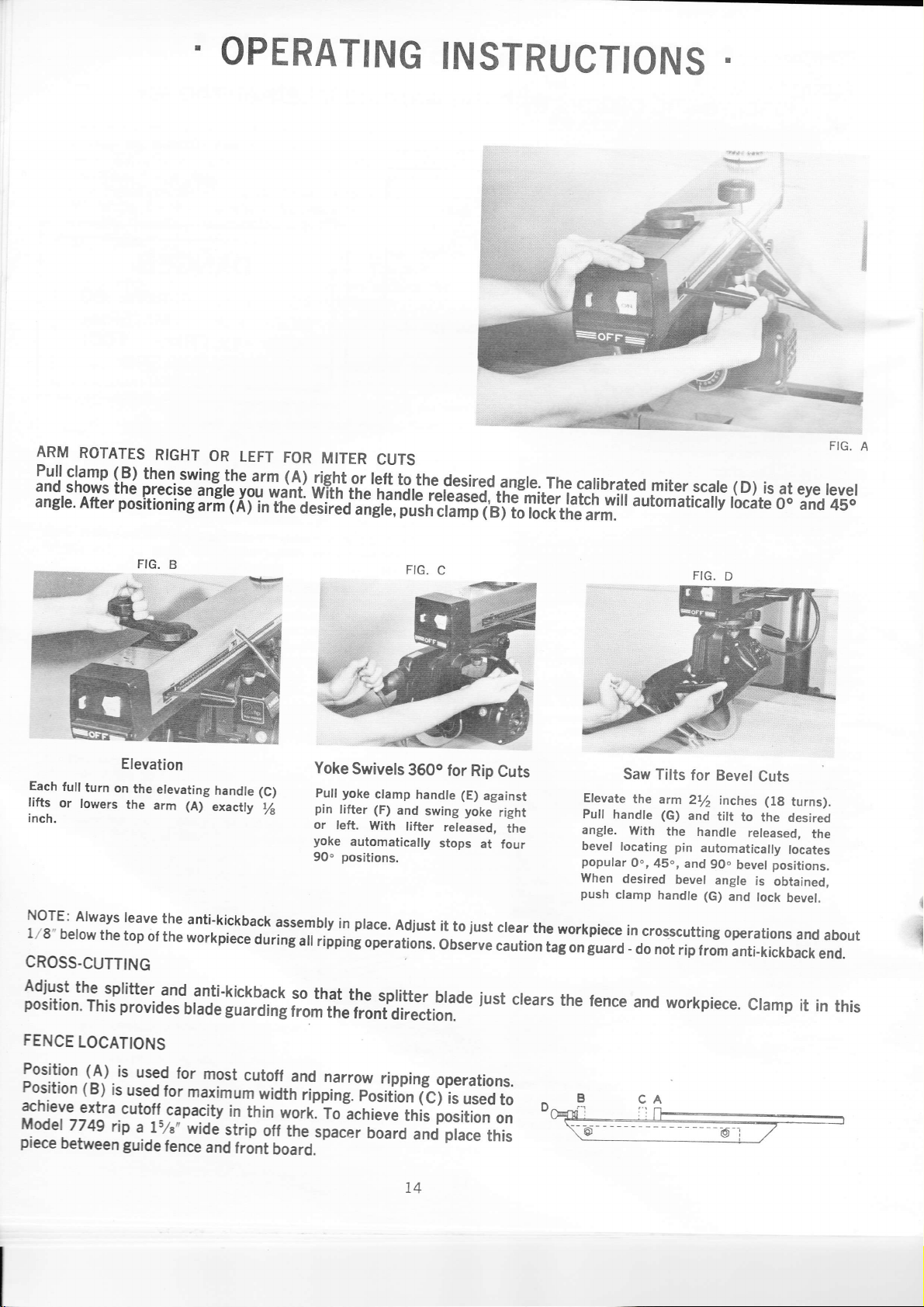
ARM
ROTATES
Pullclamp (B)
and
shows
angre.
After
the
positionine
RIGHT
then
Yilg-lh:,rm
orecise
angtq
arfr'(Ai
OPERATING
OR
LEFT
FOR
MITER
(4).rig.trt.gr
ygg
wa'nt.
wTtrr
ir-ide;i;;a;dE,;;"rr,irliiii
CUTS
left
tii"'iririilrci".i"iiii-tmit";;i;ri-;fiiautomaticary
to
INSTRUCTIONS
the
desired.angle.
el
to rock
The
the
catibrated
arm.
miterscate.(D)
I
rocate
is
at
0o
eye
and
FIG'
tevet
45o
A
Elevation
Each
full
turn
on
lifts
or
lowers
the
the
inch.
NoTE:
1'28"
CROSS.CUTTING
Always
below
the
leave
top
elevating
arm (A)
the
anti'kickback
ol
the
workpiece
handle
exacily
(C)
/s
during
Yoke
puil
pin
or
yoke
90"
assembly
all
ripping
Swivels
yoke
ctamp
tifter (F)
left,
With
automatically
positions.
place.
in
Adiust
operations.
3600
and
lifter
handle
swing
released,
stops
it
observe
for
to
l"1il'Jihil#:"J.il1[t'ilt'i:ff[;:ji,x'.?:,i1,]j;,:,;de
FENCE
Position
Position
achieve
i'!o0"1
piece
LOCATIONS
(A)
(B)
is
extra
7749
rip
between
is
used
used
cutotf
a Ls/e'
guide
ror
most
ror
maximum
capacity
wide
lence
and
cutotf
in
thin
strip
front
and
width
worrl
off
tne'space.
board.
narrow
rippine.
to-acrriere
ripping
posifrJ;l'c)IJuseo
board
ttris
and
operations.
po}iion
prace
t4
Rip
(E)
yoke
iust
Cuts
against
right
at
four
crear
caution
iust
to
on
this
the
the
crears
Elevate
Pull
angle.
bevel
popular
When
push
workpiece
guard
tag
on
the
handle
clamp
rence
Saw
Tilts
the
arm
(G)
With
locating
O",45",
desired
handle
in
crosscutting
-
do not
and
for
Bevel
2t/.
inches
and
the
tilt
handle
pin
automatically
and
90.
bevel
angle
(G)
rip
from
and
operations
anti-kickback
workpiece
Cuts
(lg
to
the
released,
positions.
bevel
is
obtained,
lock
cramp
turns).
desired
the
locates
bevel.
and
it
about
end.
in
{
{
this
Page 15

TYPICAL
RADIAL
(SEE
PAGE
CUTS
ARM
14
FOR
WITH
SAW
FIGURES
A,
A
B,
C, D)
ALWAYS
WEAR
ERATION
{1}'
NOTE
WEAR
DUST
IS
MASK
DUSTY.
r.]]lii.i
It$l
GOGGLES.
IF
OP.
Read
Fig.
guide
.tence,
wrth.the
position,
ctamp
handle.
taDte,
against guide
across
tor
Lb
ryooo.
through
return
saw
The
model
geqsor.y
justa.ble
9t- lhe
necessary
tormtng
repetitive
CROSS
A.
Set
Arm
at
0o
latch
Place
cut
bring
behind
cut
cutting
on
in
lock
lence,
lust
saw
Alter
"Roller
stop
miter
securely
the
not
the
wood.
blade
35OlO
is
available
cross
btade peyon9
to
complete
CUT
at right
tEe
column
arm
material
draw
lar
enough
blade
completirie
guide
Head
lor
use
prevent
to
the
the
cut
operations.
angle
mi6i
slot
with
on
saw
to
comoletelv
fCnce.
Stop"
as
an
position
wh'en
to
the
liiii.
at Oo
ai
wori
blade
sever
cui.
---'
-
ac-
ad_
motion
oer.
Pull
arm
desired
miter.
and
right
clamp
tion
same
clamp
angle
latch
locates
hand
handle
as cross cut.
MITER
handle
shown
on miter
the
angles
to lock.the
adtohatically.
IMPORTANT:
and
popular
arm.
swins into
scaE.
The
lelt
hand
push
Cutfing
ac-
Check
This
position.
RIP
cut
desired,
against
guard
assembly
cut, hold
back
leed
kickback
Lower
operation
machine
on infeed
to
hold
materialfirmly
against
material
device is
Guard
PLOUGH
is
done
Lower
then
guide.
lrom
with
dado
lock
arm. Be
side, lower
material.
down
Feed
side
located.
precautions
dado
head
for
carriase
surE
anti-kickbacli
When
on
evenly.
on
which
page
on
head
Oe*tr ot
sCuretv
to
adiusl
startins
table
Never
4.
in
anii
anti-
Read
IN.RIP
tig'
c'
start
with
arm
locled
in
cros
rerrJor
H,l[r:,L:J.]LTolls_0..,
t,
t
BEVEL
Read
Figs.
cross
cut
saw
by rotating
bevel
clamp
motor
in
on.
bevel
quickly
locates
positions,
desired,
motor
in
CAUTION.
contacting
-C,lq!gr
slrghtly..so
guard
than.
hits
CUT
B
position.
handle
yoke
scale.
0.,
lf
any
bevel
position.
Prevent
the_base
45o.
that
the
base.
and
crank.
to
angle
Locating
45",
other
clamp
the
at
titt
the
rear
OFF
D.
Start
Elevate
Release
and
desired
an?
angle
will-hold
blade
angles
the-guard
oJ
the
tilt
pin
gO.
trom
the
in
is
.
of
desired
width
of rip,
using
rip
l|jll13.jj:.1-?lg!l,l:ht
lower
than
material.
Slide
the
leed
3q1I:l-gIiq9-shipr
rflcr(BAcl(
ANTl.K
See
stDE
ICKBACK
accessory page
ANTI.KICKBACK
1.
Disconnect
2.
Rotate
the
3.
t
Adiust
Lorer
xorkpiece.
$ide
backrards
tie
lhe
the
adjusting
upper
splittcr
rorkpiace
0F
the
Locl
lf
GUARD.
electrical
guard
it
ihe
fingem
and
securel;
eventy
SPREADER
screw
to
anti-kickbacl
under
scare,
materiar.
piece
into
F0LLOW
WITH
t9
for
porer.
to
center
drag
in
this
lhe
do nol
teft,
and.rock
ol
uw
btade;
tr{sTRUcTrO-nS
SPREADER.
cataiog
the
lightly
on
until
pmition.
anti'kictbact
preyent
AND
OUT-RIP
pcition.
cut
tor
rowe,
our.rip
or inrip
srr.r,irgr
anri.riciua*
to
be
cut
give
it
a chance
Or
cluiroi
Pull
out motor
poiirion,
uyiilii.ririiip
isemrp
to
ilc.
n-uildir.
OPERATING
splifler
blade
in the
Ihe top
surface
the
anti-kiclbacl
fingers
backwards-moremenfrepeii
ol the
in the
kerf
workiliece.
lingen
to
end
and tock
pull
ol arm.
ple
yoke.#;;;ili;:
r.ri.'eri;J'r"#;";'#:ili:li;lr:;
si
uriifiil;;;;;;p;;;imaiery
cr
INSTRUCTIONS
made
by
the
blade.
Loct
are
about
normal
rip
direction.
step
f.
it
I/g,,
securely
betow
Try
FOR
in
ttre
to
clamp
RTPPING
position.
this
top
pull
the
handle
iocate
FRoit
surtace
wortpiece
rzE
against
saw
incrr
AilTt.
ot ttre
tor
15
Page 16

7
*w+$k*+!ii}!nwil$i.;ie
COMPOUND
Read
Figs.
in
bevel
arm
arm into
u.sually45o
then
Pull
The
srmpty
miter
IMPORTANT:
A,
cut-off
.clamp
desired
or
relock
arm
saw
across
-compound
a
combination
cut.
B,
and
position.
handle.
miter
in
between
clamp
for
miter
Check
MITER
D.
Swing
position,
angles,
handles.
miter
cut
bevel
Lower
Start
pull
the
cuts.
and
Guard
is
Re-read
elevate
in
shaper guard
Swivel
so
rial.
lock
Feed
against guide.
bevel
precautions
RABBET
Figs.
arm
90.
that
Use
to set
on
until
vertical position.
motor
guard
column
dado
material
rabbet
cuts,
page
4.
B,
C, and
over
into
sets
crank,
for
evenly,
Tilt
motor
dado
rip
above
cut
motor
D.
First,
locates
place
head.
position
mate-
also
desired.
firmly
for
rip
Read
bevel
scrib€d
into.
r.ip
lock)
lock
desired
guard
the
anti-kickback
use
a wood
prevent
ther
ALWAYS
WEAR
ERATION
DUST
BEVEL
Figs.
B.
cross-cut
above.
position
securely
point.
at in-feed
"pusher"
kickback.
NOTE
WEAR
MASK
IS
DUSTY.
RIP
C,
and D.
position
place
Now,
Be
(using
arid
against
sure
oosition. adiust
rievice
board
GOGGLES.
IF
Start
as de-
the
saw
rip
aim
to lower
and then
to fur-
OP.
in
at
Place
shaper
arbor;
cover
Now,
set
position
same
s.haper
desired,
secu.rely,
so
that
rial.
Feed
and
evenly
-
cutters.
pressure,
SHAPE
cutter
with
up
the
cutter
Lock
adjust
just
it
the
into
Maintain positive
on
shaper
macliine'in
as
RABBET.
for
the
saw
carriage
shaper guaid
clears'the
material
the
motor
guard.
the
Set
profile
mate.
firmly
shape-r
Replace
head.
Use
dado
cuts
When
determining
simply
touches
lower
dado
Each
full
one-half
Wide
dado
by
making
across
saw
lower
top
turn
turn
the
16
for
same
material.
DADO
blade
across
as
depth
dado
until
of
material.
head
as
equals
1/1G
cuts
can
successive
with
or
saw
desired.
t/s
inch,
be
dado
angle
blade,
of
cut;
it
iust
Then
inch,
etc.
made
passes
|a:r
---{:6
Remove
collars
onto
wherever
For
only,
the disc
on-
fixture.
the
position.
evenly
finer
DISC
arbor
place
in
arbor.
desired
bevel
place
sander.
angles,
For
disc
sander
for
paper
Locate
and
shaper
use
surface
Feed
best
for
SANDER
nut.
Leave
and
thread
disc
on
surface
guard
For finish
work
sanding
into
the
results.
final
finish,
both
disc
sander
machine.
sanding
ovei
work
suppod
tilt
vertical
material
Use
Page 17

It
machine
The
it
is
best
is
important
seems
to
cut
following guide
perlorm
to
to realize
inaccurately,
is
listed
oll
ol
the
ALIGNMENT
that
an
improperly
its
adjustments
for your
alignment
procedures
GUIDE
FOR
adjusted
and
convenience.
when
ACCURATE
just
saw
alignments
However,
correcting,
CUTTING
will
not
should
chungirtg
any
one
yield
be
checked.
one
prctblem.
the
accurate
adjustment
cuts
u,ill
desired.
alJect
If
another,
the
so
l.
2.
Lumber
away
or
3.
Saw
ploughing.
Saw
will
cross
cut
cut.
from
ploughing.
stalls
Pnosrsl\a
not
or
a
has
a
fence
*'hen
make
good
tendencv
when
ripping
ALIGNMENT
a
square
45"
miter
to walk
ripping
or
GUIDE
Possrst-e
Arm
is
fence.
Arm
Column
not perpendicular
has
excessive
is loose
Too rnuch play
column.
Roller
head
Yoke
too
head.
dust
fence.
not
fence
edge
blade
blade
not
rate
blade.
too
much
head
loose
between
loose
parallel
of fixed
or
straight.
too
loose
play
too
when
roller
Saw
guide
Table
Guide
Rear
Saw
fence.
fence.
Dull
Fence
Feed
Wrong
Column
Too
column.
Roller
Yoke
head.
Saw
dust
FOR
Cause
play
in
base.
between
too
loose
when
between
with
not
straight.
board
is
not parallel
cutters.
fast.
in
base.
between
loose
in arm
clamped
lumber
ACCURATE
guide
to
at
end.
arm
and
in
arm.
clamped
lumber
arm.
not
and
straight.
with
,.*
,nd
to roller
and
fence.
CUTTING
Adiust
fence.
Tighten
Make
Make
Adjust
to
Adiust
Keep
Make
Replace
Sand
Make
Adiust
fence.
Sharpen
Replace
Sl"*
Use
Make
Keep
cross
proper
proper
roller
yoke
table
proper
fence.
or reola<
heel
cross
or
Fence.
f..d
correct
proper
table
Solu'rroN
cut
adjusting
adjustment.
adiustment.
head
clamp
top
clean.
adjustment.
adjustment.
cut
replace
*tt
blade
adiustments.
top
clean.
travel
screws.
correctly.
handle.
travel
blade
guide
with
with guidt
4.
Saw
giving
blade
good
a
scores
finished
lumber,
cut.
not
Saw
Column
column.
Yoke
roller
llcnt
Not
fceding
uslng
desired.
blade
is
too
too
loose
head.
blade
or.dull.
sa*,
lmproper
heeling.
loose
when
properly.
blade
t7
in
basE.
for
clamped
finish
.-
cut
l\,lake
I'lakc
Replace
Draw
a slow
Change
heel
proper
blade
saw
blade
and
blade.
adjustment.
adjustments.
across
pull.
steady
lumber
with
Page 18

PRosmu
PossrsLp
Causn
SolurroN
5. Saw
to
when
6.
Cut depth
of stock
7.
45'
blade or Dado
push
lumber
cross cutting.
varies from
to
the other.
bevel
cut not accurate.
blades
tend
to one side
one
end
Saw
blade is heeling.
Column
Too much
column.
Roller
Yoke
roller
Fence
Duln
Table
Column
T-
column.
Saw blade not
table top.
Column too loose in
Too much
column.
too loose in
play
head
too loose
too loose
head.
not
straight,
Ea
rcr
top not
too loose
pt"y
**h
play
base.
between
in arm
when
cutters"
parallel
in
with
base.
b.t,*.,
perpendicular
base.
between arm and
Roller head too loose in
Yoke
too
loose
when clamped to
roller head.
Bevel clamp
Table
top not
handle loosc,
parallel
with arm.
arm and
clamped
arm.
"..
arm,
to
,"d
to
Make heel
proper
Make
Replace.
R.pt'rce
Adiusi
\lake
Make saw
Make
o. ,h*p.*
rabie top
proper
proper
adjus'rment.
adiustments
pararel
adjustments.
blade adjustment.
adjustments.
with
arm.
8.
Saw tends
lumber
9. Saw
in
0. Miter
various
l
Elevating
elevating
12.
Clamping
miter
13.
Clamping
at
bevel angles
too fast.
does not
tracks.
scale
miter
angles
to advance over
traverse smoothly
not accurate
angles.
handle
or lowering
force not
force not
other
other
slips
su{ficient
than 45".
than 45",
when
saw.
sufficient
Roller
adiusted.
Dull
Not feeding saw
Dirty
Bad bearing.
at
Scale
Belt
Set screw
Base
at
Arm
Bevel
head bearings not
blade.
properly.
tracks.
pointer
tensicn not sufficient.
in elevating
not adiusted
clamp out of adjustment.
clamp handle too loose.
not
properly
arm loose.
properly.
properly
adjusted.
Adiust
Replace
Draw
a
Clean.
Replace
Adjust
Adiust belt
Tighten
Adiust base
Adiust arm
Adiust bevel
roller
head
or sharpen
saw blade across lumber
slow and steady
bearing.
pointer.
scale
tension.
set screw.
to column.
clamp.
clamp
bearing to arm.
with
pull.
handle.
18
Page 19
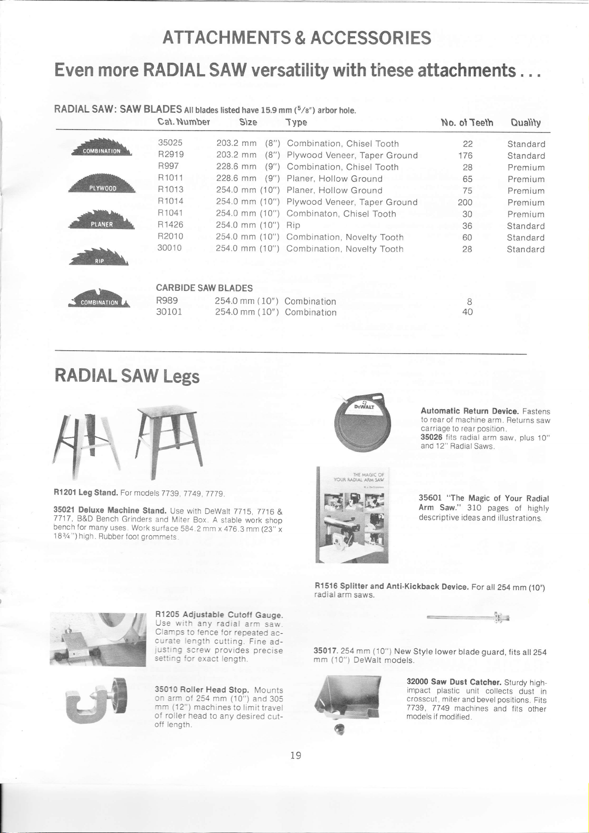
ATTACHM
ENTS
ACCESSOR
&
I ES
Even
RADIAL
-#lr
^#t
-lill"
+\
.ffi,
more
SAW: SAW
RADIAL
BLADES
Attbtades tisted have 15.9 mm
Ca\.Number
35025
R291
I
R997
R1011
R
1013
R1014
R'1041
R1426
R201
0
3001
0
CARBIDE
R989
30101
SAW
SAW
Stze
203.2
mm
203.2 mm
228.6 mm
228.6 mm
254.0
mm
254.0
mm
254.0 mm
254.0
mm
254.0
mm
254.0 mm
BLADES
254.0 mm
254.0 mm
versatility with these
(5/8")
arbor hote.
Chisel Tooth
Veneer, Taper
Chisel Tooth
Hollow
Hollow
Ground
Ground
Veneer,
Chisel Tooth
Novelty
Novelty Tooth
Taper
Ground
Ground
Tooth
(8")
(8")
(9")
(9")
(10")
('10")
(10")
(10")
(10")
(10")
(
10")
(10")
-Iype
Combination,
Plywood
Combination,
Planer,
Planer,
Plywood
Combinaton,
Rip
Combination,
Combination,
Combination
Combinatron
attachments
No.
Teeth
of
22
176
28
65
75
200
30
36
60
28
8
40
Quality
Standard
Standard
Premium
Premium
Premium
Premium
Premium
Standard
Standard
Standard
. .
.
RADIAL
h
R1201
Leg
Sland. For
35021
Deluxe
7717,
bench
18%
B&D Bench
for many
")high
Machine
Rubber
SAW
Grinders
uses.
Work
loot
Legs
modets
7739,
Stand.
and
surface
grommets.
R't205
Use with
Clamps
cu!'ate length
JUSt
setrrl,.)g lcr
7749.
Use with
Miter
Box. A
584.2
Adjustable
to
i-o
screw
7779.
DeWatt 7715,7716
stable work
mm
x 476.3
mm
Cutoff
radial
any
fence
cutting.
provides
exact length.
for
arm
repeated
Fine
precise
shop
(23,,
Gauge.
saw_
ac-
ad-
Aulomatic
to rear
carriage
35026 fits radial
and 12"
-IH€
M6iC OT
YO$A
RA'IAI AIff
5A!{
35601
&
x
R1516
Splitter
radial
arm saws.
35017.254
(10")
mm
and Anti.Kickback
(10")
mm
DeWalt
models.
Arm
descriptive ideas
New
Styte tower
machine
of
to
Radial
"The
Saw."
Device.
btade
Relurn
arm. Returns
posilion.
rear
arm
Saws.
Magic
pages
310
and illustrations.
For
afi 254 mm (10,,)
_ .-_,rlr
guard,
Device.
saw,
Fastens
saw
plus
ol Your Radiat
of highly
e
;I-
fits ail
2S4
10"
35010
on arm
(12")
mm
of roller
length.
off
Roller Head
ot 254 mm (10")
machines
head
Stop. Mounts
to limit travel
to
any
and
desired
305
cut-
19
32000
Saw
impac't
crosscut,
7739,
7749
models
Dust
plastic
miter
machines
if modified.
Catcher.
unit
collects
and bevel
Sturdy
dusl in
positions.
and fits
high-
Fits
other
Page 20

f
RADIAL
Make finished
surface
mouldings
special
shape with
and
woodworking
w
ff3&
tl-
a
R3076
;
I
R6478
Economical
R6500
(%")
mm
Starter Set and Knives
3-Knile
arbor hole.
ra.
T
Z
R6515
ffi
t
;
I
R6520
L
R6524
;
a
R6521
RADIAL
SAWS
edges for
cabinet making,
Deluxe
Work.
30024
Knife
38.1 mm (11/2")
hole
Panel
R6480
38.1 mm
Sets of
mm
11/2")
held
R3076
R6477
Panel
R6478
radius.
R6501
Head; 1
Universal
Lip Knives;
Cove Knives.
Shaper Head
R651
7
glue
many
different knife
effects.
30025
Converts
and
fence
Shaper
Jointer
Shaper
and 50.8
Raising
2-Knife
(11/2")
2 Knives-Self
(1/4"-3/8")
long.
High
by
6.4 mm
mm (%0")
B
50.8 mm
Raising
Cabinet
7o rake
3-Knite
R6505
Bead Knives;
1 R6517
Sets of 3 Knives:
R5505
Glue Joint Knives
R6506
Ogee Casing Knives
R6512
Universal Bead
R6514 Panel
R6515
Cabinet Door
R6517
Knives
R6518
25.4
R65'19
Tongue Knives
R6520
Groove Knives
R6521
6.4 mm
Quarter Round
R6522 Triple
R6524
Base
34003
Tool
guard
blade
sanding
commodate
SAWS
30020
work the fast
plastic,
blade.
R8028
sists
Coarse.
Shape
jointing
& Knives Yield
Head
Head
wide,
mm
Knives
Shaper Head.
wide,15.88
thick,
speed
(t/0")
Knives
Door Lip
Shaper Head
Glue
for Radiat
8 mm
and
long
sets for
panel
Shaper/Jointer
saw for
jointing
(2")
(2")
operations.
1lsz"
has
&'tha" adjustments.
& Knives
(R6480)
15.88
Jointing/Surfacing
(R6477).
mm
Aligning.
25.4 mm-38.1
steel with
socket screw.
Bead
and
Jointing/Surfacing
Knives,
Joint
1 R6515
8 mm
and Tabte
Cupboard Door
(5/6")
(1")
mm
tools
Straight Knives
(1/4")
and 12.7 mm
Knives
mm
6.4
Mold Knives
Guard. Replaces
for
shaping,
planing
operations.
up 1o203.2
Saber
Saber Saw.
easy
metal.
Saber Saw Blades.
of one each: Fine,
&
Joint RADIAL
boards.
ralsing
precise
Edge
decoritive
and
other
Fence.
shaping
&
35500 Router
router
applications.
Uses most
ln feed
RADIAL
R1208
Finest
Quality
includes
Set
:127
127 mm
Lip Knives
Bead
1t1o"l
(5")
mm
mm
1s1u")
(5")
(%")arbor
6.4 mm-9.6
mm
one hole and
Cove Knives
9.6 mm
Set. 1 R6500
Knives;
1s7,u"1
Knives
1 R6512
Cabinet Door
Bead
Saws,
Knives
and Cove
Bead
standard
jointing.
mm
Knives
Will
(8')
Saw
Does
way
in wood,
Complete with
Medium,
2-
tong,
arbor
and
long.
hole.
(1"-
and
(s/u")
and
15.9
(1/2")
disc
ac-
dia.
curve
Con-
right
horizontal
RADIAL
Rotary
faces
R6380 Rotary
wrench).
thickness
R6383
Disc
R7470
Set
mm
disc
Surface, end
30016 6 assorted
sensitive
60,
Drum Sanders.
30092 3'
Drum
arbor
(12')
to
up
30091 2'
mm
arbor
(12")
delicate
30090 1'
mm
arbor shaft ol
(12")
delicate
RADIAL
These
drawer
Finest
R6024 152.4
Flat
(';"),
bore.
R6001
low
(',:"),
bore.
R6025
Ground
1
Chipper
SAWS Rout
Attachmenl. Holds
motor for
overarm routing
ldeal for
Router motors.
SAWS
9.6 mm
hand
(3/8')
arbor on models
drill.
A must
SAWS
planers
with either
Knile
Sander.
203.2 mm
(includes
(8")
No. 60
3 No. 80
Sander, 15.9 mm
shaft ot all 254 mm
models
50.8 mm
(3")
shaft ot
models
(3")
models for
surface and
straight or
Planer
Surface
panel
sizing,
Set. 2 Knives
15.9 mm
bevel edge disc,
pressure-sensitive
dia.
grit).
grain
sandpaper
(76.2
dia.
long,
sanding.
dia.
long, 15.9 mm
sanding.
203.3 mm
grits).
mm)
for straight
(2")
thick.
(50.8
15.9 mm
254 mm
all
for medium radius
(25.4
mm) Drum
all 254 mm
small radius
SAWS
great
DADO
mm
(2
Blades, 4
1.6
(2
Blades,
.6 mm
(6")
(8")
SETS
and
mm
(116") 15,9 mm
corners, rabbet
Quality Cut
Ground
1
Chipper
152.4 mm
Ground
1
Chipper 1.6 mm
203.2 mm
(2
Blades, 4
'1
variety work.
Drill
Drill
chuck w/key
7739
&7749 tor
for dowel
(includes
planes.
raising.
(8")
Fast material
and
bevel sanding.
discs
dia., 76.2 mm
(s/e)
mm) Drum
(5/8")
(5/8')
cuts, with Spacers
Precision
(6")
(%6")
Dado
4
1r7,u")
Dado
Chippers 3.2mm
jointing.
Plane
size boards.
curved edges.
knives
Excellent for
for R6380
(%")
L.H. thread.
dia. Sander Disc
one
sandpaper
(8") pressure-
(1
No. 50, 2 No.
L.H. thread.
(10")
and 305 mm
and curved
Sander, 76.2
thread.
L.H.
(10")
and
curves
Sander, 76.2
L.H. thread.
(10")
and 305 mm
curves
Dado
cut uniform
over Longest
Dado
Head
Chippers 3.2 mm
15.9
Head
Chippers
15.9
Head
(%")
fits
and
203.2
removal.
(3")
tong
Fits
edges
Fits
mm
305
and
Fits
and
slots,
Set.
(%")
mm
Set. Hol-
3.2 mm
(%")
mm
Set. Flat
(,/s"),
bore.
T+
&
Sand
Sanders f inish
*
-*]
ffi^
W
E
B
sx
grooves,
and
half laps,
Chippers Assure
Life.
,r'E
sur-
.(
20
Page 21

MOTOR
OVERLOAD PROTECTION
Your Saw Motor
the
following
l.
Press the
2. Allow
further
3. After
Motor will
Motor
will
"BLOW."
Motor
fails to
(Power
output
rapid ly with
at motor
Motor
starts
come
up to full
Motor
overheats.
Stading
operate,
M.t.r
.trll.
fuses
or
Frequent
circuit
breakers.
steps:
"OFF" button
the motor
until
the reset is
TROUBLE
not run.
run
not
develop full
of motor decreases
decrease in
terminals.)
slowly
speed,
relay in
motor will
(r".rltirC
tripped
circuit
opening
is
equipped with a manual-reset
on the front of the
to cool, and then
you
hear
do
accomplished,
a
"click"
TROUBLE
fuses
and
press
when
the
saw
SHOOTING
PROBABLE
Protector
Low
Short
plug.
Short circuit in
or loose connections.
power.
Power line overloaded with
lights, appliances
voltage
motors.
Undersize wires
lons.
General
company's
sections
mand for
ceeds
generating
systems.)
Incorrect
or fails
to
Low Voltage
starting relay.
Starting
Motor overloaded.
Improper
tion restricted
due
not
Bur:red
extended
caused by low line
etc.
Open
Loose
in motor
l" bl"-"
breakers).
Starting ,'elay not
Vc:age
n:oior
snped
Fuses
not
of fuses
or
Motor
Fuse-
have
not
overload
arm.
the red RESET
the button is
may
be started by
CAUSE
open;
voltage.
in line
circuit
protector.
pressed.
circuit broken
cord or
junction
and
or circuit
overloading
facilities.
of the
electrical
the capacity of existing
and
fuses in
relay not
cooling.
to sawdust,
relay contacts
hold-in
relay
coil
or
broken connections
terminal
of
(ln
country,
power
distribution
power
will not
-
operating.
(Air
circula-
through motor
etc.)
(due
periods
voltage,
box.
operatrng.
.c!v
icc
ic reach
or
circurt
have sufficient
ic
!er'^-t,t
cperat ng
breakers
capacrty.
overloaded.
sufficient
capacity.
protector
button. If
pressing
If the
you
the
do
"ON"
not hear
"trips" and stops the motor,
a
button.
CHART-MOTOR
protector
Reset
box,
other
too
power
many
de-
ex-
line.
trip
do
to
(indicated
Check
lnspect line
sulation and
lnspect all teminals in
loose or shorted connectrons.
Reduce line
lncrease wire
Request
company.
lnstall
Correct low voltage condition.
Replace
Correct overload condition.
Clean out sawdust to
culation
Replace
I
Replace
f
Replace relay.
Ccr.ect the
Replace
capacity unlts.
Reduce nrotor load.
by audible
power
line for
cord and
shorted wires
load.
sizes,
a voltage
correct fuses.
relay.
through motor.
relay and
relay.
lovr
fuses
"click",
REMEDY
allow the motor
pushing
by
click).
proper
plug
motor
reduce
or
voltage.
for damaged
junction
length of
check from
provide
check line voltage.
line voltage
or circuit breakers
normal
condition.
on
red button
the
with
take
to cool
in.
box for
wiring.
power
air cir.
proper
For
Wiring
Diagram
see
Parts Bulletin.
(motor
does
speed.)
not reach
2t
normal
l
I
Page 22
FACTORY
^'-i?iy$.:"[Ufii?;';g';;[',:,""":":l'"":,9,::t
phoonixSsr3.4slNonhTihavenue
ARTZONA
AB(ANSAS:
Liftl€Rock72201S19WesrS€venrhSi@er
CALTFOFN
A
Anah€,fi
92&r.
t2J5Souih
yraronn;i.,^;i;;;--"':
rresnos:z,o
rc;oe;rs-sis,:d:r*:,:ili;"i"""
llrif**mffii*,*l*.,,"."..
s*6":i"-i:i)s'iijr'r;,i,ii,ll"
s.D";"trii5;i;
s""
-;iir":"
mii*,i,.i:i,'
*',;:lilffI['1,#';i{ni"fi::;""
;":"1"::trll;,'f.*r;;if;,.'"*.0
w*,c.;;"".,9ii-r'^ti;;t";i;"^*^"
COLOFAm:
&nver&219,
CONN€CTtcUl
O,.nOeffi177,.gr
_ronroo,wa,.+.i,mrm'ss-:st.!','*..;ilsi^".,
0ISTRTcTOFCOLUMB
:-;i{:8::tJt
.
FLOFIDA:
il"'*,"i1f!i*i
A W.rhd.r.^
y:;r::_gili...T"::;::;:}""1
Ja.r30nyIe32205,92OCassarA!enu.
,,f
Er. . av.i
"
.;;;:"j
"
*-."".''
j171
$urh Federa
posr
Boslon
ti;";i:;;;'."'';'"'1,::"
'-
""''
tuu evard
n.an
gfl+fltfl{1ffi;;,ti#+r+r;,=,;
w":i e" ;
GEOFGTA
.",.."
HAW.
s;i.iiii6lJ,-:"'r--1lu
Slono
Mounra
"""-,..
^,.-,,1AU:;,";i;?"lT;
I
{o,
ou!%3!3
n
iaira^ra)3m&
6/5!ra.
s,eor
a c ..
c,o
-'"
-
d
^"
"o"o
:.1;,","",,
!B!
fi1
1 t
2oe.rt08'0
i::ii?,ii
111
e'6
!d iil?!.s
X'?
i;i
303 922.8325
13]
fl; i;i)ifr
!!
pi
"
gli
:3:,::;ji;
d
s
iJ:!3:ffii:ib';,'1ti".",.31".-,,:i,t:1"".i'* l;' l;tiiii
*n
r.pi,im.;i-ii"iil
.
TNDTANA
Erans!
-,.d.a..0or.,
owA
h3Mon€sr3r2
FAftsrs
4(h,d672.r,s,
xEN-Lc(,
Lore,.rc.:;;;"";,;;^...,.
-o,,sANA 8.,..%..;,;";',,;;i,'.i:""':'::
ve!.e\";a;*-'.-;m:rs.ii,."::;t-
s-.e,oor/.0(.d.t;;;.:"
'"^:r*1"",,?.-,i".1;ij,L"i*,,,',.*.
"'1*:'":.9.*.,:
i:;ri.-';".:-ilIl1ffi,if,0,:_,::?:%.
MAssAc!LS-s
e177ro
i+irfi;;
oZ*iz.o.sTu
;.,:,";,.:,;-';,,;,"'
4:":l';s.-:.,",".".
23|l
*rc^.,^_-,"^,".s"".-.,
hTFtrsrArenu.
chs..^,.
"
"i.,'.,^.,
"-
_._..*-"
"*tr##frrftlq[];$rtri;
1..,
..
" "
ie..
-',,
T!
i.:
't
rr
a::'r-,''
<.-:-.'+'
.:
I:
r
lo
2
fli
SALES
and
SERVTCE
MTNNESOTA
ll3.BS!
u
6a22796411
fl;ff;
{fl;ti
ql
sli.3i.ll
!69r/4
l::-ffi
r.rd-_
:I:;
.u-.-'
<:
F
I
f:il;
$.w
sr
i$ffi
ssouRr
ranqaqc,
372.3040
s, ha6r/.
<r*"am-.aur...or..o:is"i"i,L'.t,'
772'.a$
s,,o-s6r1.
NFBFdsh!
NEWJEFSEY
?a?'e'@
i:,f
cr2'{t
NEWvETiCO
^il,"9F.1
buraro
r"^
liii,,8
i;I:r;;i:if,,i?:".:,,:i:i:J*:i:i.
(1;:;;;
i:r.i:::'iijif
nocnesr€r
S,.a..)e.Dcw
noq.-
broonsbo.o?7!07.
qaeol)/Doa2a2oA1.1;!,.--" 9r9
orro
C,-oroqrrr
.a,-a\5i\)2?
g",o.riloe2s$so.r-o,;b;."
roredo!j607
o*repovo
-r.a7a..-
d*
oqco,
.a.
di:":..mri!;--,-:,;.:,;
p
"@o\":4.0
D.sb..o-rr2l:
ra.
li^.^:-1'.1-.:;
I;;r-:i;:e-r:i"':'-'''*
_9,r-
j-'
::::,'.
t
:s /-:!
-r
i:rq:_e:bs22ci,.^i.;,_'''
:!
.
-..
-.-.
,.-".":
r-i-
si,-_"i.,ii.:i-.".f,;i.:;*":,.,.".,
...
/-G\ a
ro'o.:rsrrrar,.""",io'i.,fo-.n
m
o,.--o-d21722.":"r;""*,r.j*ii.-,- 30ad&3Bj
*"s-rcioi-i:.
.""."0u00,0,,,,"j,'j"",i',1''r"^."^".
s".."""ermii.,.iirjiioii.i"ii,J.,""'"
wrs-v.ncri-f1";i"".:i:);l;,;*;;.,^.."".,"
*,.cors,r
CENTERS
Btoomtnglo^(Min^oaporis.sl
97j2Gadie
ra^sarL
ry64I1
412.
.rcM.^sr
/6411r
On*.63r2
ChErryHil]O&}
;a';";.""r.d:d""If.";;,:
,,e",w".,.,;<1nJ"
!bdreio.d&.0-2B.rCalderarapo.dNl
a!"-,..r-c"',2rloas-,o,.ere-...cd,Fo
r12@
33r w B rvr^ aw.
;o,i,As;i:r:"3=",,u-*,".
'-
r621
rU
c^u
ir
.'1..nr
tr,ido,:'s.;o"i'
o,,.^o."c',rr.6
j.,oso-,'s1.,d.-a.".
*
,,
e.tos_:r-.i::a.:";a;.,,"
E
.-9.5
.-,.
:*.1
:@Pa,onFoad gec.nr.j
_r;;.a-:;ii;:;:ii.ear
r::r
*c rJ."-
j;i,i;-.e.'J;",;;::.,,.
!.,..drr22192m\
v-"*.
i<,;--";:,
iorL!:.i.,;q;::;;d'
,ra.:;,'i,1",i",;ii'
e2
i1$!iikrl:#*:r:..
2s!w€il
HsnreilaFoad
r3?.d
l4se,*'a,,,-
i",.-".-"";;;.'
po
ln6
h
nr
oh
rr.or
sn",o"".".
,m-Oa,o,,a-
's'sFL,.o.,oi;.e,e
qios
roi
"
*,^,j".i.I"".:
idi"-".2:t_-s,i..
;,r
S"a
"c
Pt.,1etL..2c1,
:'il'-:"'-j.i;'";;j."
F9..
.
'r*r-
...)\
36a..,6.11...
c'.....:"s."
Road
ie
'
irrsL.^oors,.
:;.
"
i.
."".""-..
arz.
"
.,"..".-0i..;:;
tur-sa.,
i*i
rar,".s.
,."x"1,";,t:,..",
li'r,l,i"'Xi",.-
",.is;e?
ri,.i.;;,._.
;;;.:"6J"i.,,;.
"e
p.u
)512!
dAvenues;u0r
Ma nSr
'
''
;:-::::,;
-
;;,,,""""-"",
'
_
- -.""
,"".
-.
-
,e;.
"".
-E.:
i"
-
es o.
5.
alrc,
"
aD.2
-0,
i"
.
"
.
..
rd,oor
" ""
"
*.
^,"
..
","
"
2;t,x;i;
703sr7311
.0.
265.1170
2ft
s0.399'g
26
:g:
612
3t6
.316
1'l3ed36'
1:i,
.92.s66
402
)d:3111
2i:
20-s.'70{
io5
ss...m2
7B5rB6/
5.s
7'6
aat'))'
ii;
;::31fi
i:i
ii:#"i
l;:
;;:#;
352"'m
o
o
31'4?07
2o
65
64
2"adr'
5'r
2s
a 0
!roo2'
{:
).._:..
{3 23&.
L.La5n.
2.'
7.7
!(rr.
-
a.)..
: i
*,..r,
..2
*..)-x
?,5
@{767
#l
;;SI
b.5
6a0o2.
s1B2'!11
6'5
3r132'7
36
l/,,s.
;::il;
:;,
21%1142\
01\
773o7'o
317
rt0'7\
t
r 6e2711-
lot
s6b2?2
uoot*
2326.3?
.7360.n
i:l.3ifli
S4.srgr
!r&re
sJ
,"i,i,n8
42.
a''
G,i
AUBAMA
Moilgomn,
0*srlu*n
Sie,ned
Alrbam!
tot(
AU\(A
An.hotsge9950
asokR.aftmEry
turbailr9970t
lirb,ilsAerc$r,(et(
Po*e.
Iod
!
AR&ISAS:
lone$oro
Ailan$s
id6r
Gtll0RrlA
naio9l702
I
I
Wane
4621 hd H:nn
Monkbe
o 90640
Ads(P
E(n
t([rr;r&Mililnec,.
!ifriirro9!
L,rg&0ppn
Sanlos95:t?
Pe.soiM{i!nn
C0L0qAD0
Deivr
Bade
Tn
$a.. i!
0,&- Fi.":ta!ikf
urr:"j-
(l\tt r '
f.rP
ur-
l,
Wre.
V;:'
:.:"ilik:&n::
a rhiFr?t1r
trn
3.Jn & tr
GtnR6
4 Uem
(
w
IirmsCo
HAWA
I BlDq672O
pimqMil
Ha,ir
Kahu!
MzrL96712
M,!
Po*n ler
IDAHo
Bo*81706
Ms-an
E{r
krtrhi8l50t
Wrdr
s\a*
& Itot
E GildrnCmb
35660
Mdo'Silrte
Mafumry
72101
r t
(omEry
(
I 4t58d
82r1S5t*l
{t829!
8C?0{
.;-,
M.r
"!
:t4:
t.j
-.,::
i.
: 20,
5t55Litl
808
p0
!^.p
?08 14! 65rc
(
tump.il
2087162421
5I Ih
16t08
90i?7Z5Zl2
ponRed
20
9O/1796686
Ph,o\trd
Sa
* 725 w*r
(r.5!pp,
209255
2lt i2 Asr
gti
?7 iFaar
t{r:
?6!i.rq:.
t::tli.r:!rr:
r
::tt
:::
- -i r!::
V.
:.;j: r
::i: \ w
": i!
9t1t:2rri
r
P
L, 2:ti
9l? i.:
1675
9X
Sort:i
803877 rui
?51 broirE4
?4?2 M! i
n h{
ZO5252lsor
t5t5
t
rc ITt4WirSt
[806
t6tl
w.i
Wr
54t?
!:.!l
I
E.: :i
:'
.-
:i.
i.
E:r:i:r:
i!t:
lpq
kGlu,sr
Bo 605q0
ilaCrM
bn s
nr m,,,,:
rip
re-.
r: !
D€Walt
d iid
AUTHORTZED
lilDlAilA
IOWA
t0UrS AilA
MA Nt
MARYUND
MASSACTUSttrS
Maki!N
il \\!jia
c
\ai
'E:Ivry:
Llli!:
t}ri!:
srTs'1!
iS
fome&
TNDEPENDENT
ll warne
46808
Arrei
id6talSuoot,tnc
ndaDp
r46?0!
(rshiMilhi{,(0mFo
De5 tiloloes
50322
louMrh neryComFry
B.bi
Rou,e i0305
Biloo Roq?
thdaMoror
8risu04101
869g &SoN
TMon2t204
ceCoh0ary
loiS,* F
Qri.,02169
&* Seryft
Pil61s49770
!atta!6ll
ljieC+p559,
tu{.l: Veh
I |
5:!i?
n -:,:::ll
,.
.
i:::.
i-_!
'::!!- I
ir l!:l:
:!at!
: {:: il1a
: {:
lr.CihEr
*re
idunlte
b*reia01843
8
SMOen
rg Co
61717t0400
Mda'Varo
iTCl *andlret
!122i505ri
:
E-
_ i:_.
-r
-:
!:9:!r-.:tl
H1a
:
3i.trr;^.:A,ei_
7:,!ilir_'
ir:
ll571
207 94768u
92 Psry
204 w4hig&i
5)77517i83
r.:^r
.:
:
lli:i:
:::!i:,e?1
5 t!iil68i
?SThiiFlhrd
I H
Duci &tr
Aos6i16
Prec
Pore5
2!D,laE('r'
;-. li,:rar?
!,-.. t
;-_:ie"!.-r.e-:Ct-mJar
\:-rq-l:.!ra,:i!
:: :!
:.--i!!ar:a:
i.:i.
grfl!!1.?17
0
219{8}7r2r
46?t
hetui@B!d
lrT619lllt
6l?ilodi0!irareSn.er
5t5 282
Olii
t205
70th
\e,v@
Rd
301 321 9O3l
8723
i Mrander
mSnre
106Sil igtetd
5t61473,7
Ur Lt
5071I616
g
e1
* 2t0
.i
rLsl,3
t3::!
{8,5r!!!a,i
!
::l llt
-r.rrii
it!6
}1 :i :lr! \r-
:i
:2:!
'1
,.
:2lt
SERVICE
5409
tu.mp{e
Uoe
132
Sodi Bmadwn
SUet
o6rOrr+B0,ql
tudf sr4t
?iZ6war,3.ar
prt
igr
Sreil
CENTERS
aNHlnGIoN
Roche$er
FdiM
lSupdlhoFry
lonTH
DA(oTA
Acme
t.ctrc
A.me
Ele*nc MohComoary
0Hl0 Cdm44706
E
ectr Ssr
Cnomd
Sloaiflach
CkYebid
S*$ru.e&sooD!
0(UBoMA
Whrioi
SuD0
o8tcofl
t4&e97402
lmlTodSdr@
Pod.id97209
Lmni
th(|.
PtNNttLVAIrA
Po'fl
IeL$,rk
Rodils
tledr.
50UIHCAR0L
50UTH
0A(0IA
idu,lr.
Sourat57t03
Shi
Bo6toi
It{naSStE
ro
SnvceCsrer
Ilxas
Nou{m
Pil0Reryto
EEt[ Molo.an-d
The
G G W rt
H,
d.Mrhio,hmprry
Sez(e98131
Sb'
Madisy
Yrhm.98902
hF, tle*
14603
716328 t30o
BMilt
58501
Mdor
Compm,
ce &
SuptryCo
452t0
5136218131
mryCo
tic
44135
?t6252 5600
119?5bsnMd
0rhhomiCnTll06
Comorir
|
5t5wdeisr
503226272F
Motqs.dSrvr
M(iai
6bu! t7015
tr
wsrit,
rev
Moror
ilA
CrceirlF296O2
RildCil,
EkrL rt
sliil,co
605 316 1727
tq!
ooeilCo
h.tsi
iB30t
It90CoimrSt
7701
71 92r 066n
Tl40NdsdmB[d
Suppr]
6bmgany
s€.nhq8llt
206623
21t
SourhUdg
509152s55n
c Motor
Ssrce.2O5
pO
Bor97t
l0O9
t7O5 t3ii
t240
t424teilbt
4O521655Ft
l4LC W Rpii
e r( i0?9
5,70t
rLl0 w$l
4O0S
351
Wentotrth
1t1
Absdeed
206
762 7600
49TtThrdArirE
0760
Sodh
BAro
olbn AEi@
i.
i"r
80lZ7l
ililm
pod0[eBu
tuu(h AEfr!
pilr*d
R@d
AEiE
pdtsrr.
9000
om:il s
Rd
Souih
p
tn ri
HOME
Black
motor
without
Please
& Decker
USE
& Decker
components
charge,
return
Service
under "Tools
apply
to
accessories.
you
and
ryu.hayq
Center
may
any
Manager.
WARRANTY
warrants
which
anv
defects
the
comotete
Center
Electric,'
have
questions,
To
centers
This.
other
assure
in
rights
contact yow
or
(A
Limired
product
this
are
warranted
due
to
unit..
or
Authorized
the
warranty
faurty
transpoii"iiJn'pr"p.io,
yellow
p"S"..
6ir""i-Vo,
wnictr
v'ary
nJJ,r""1
product
DeWALT
RELlABlLlrY,
Authorized
Warranry)
for
five
for
one'year.
m"i"iill
OeWait
iil;*arranty
ir6r-"iit"
eLJx
service
years
or.
Service
Jp"cif
to
a oecxer
repairs,
except
for
We
will repair
workmanship.
to
any
Station
Black
listed
does
ic
legal
rights
state.
shourd
Service
maintenance
centers,
arways
not
all
and
using
COMMERCTAL
Black
purchase.
material
transportation
Authorized
the
wa.rranty
rights
contact your
adJUStment,
DewALT
& Decker
We
or
gives
which
should
Dewart
pages.
vary
nearest
be
yellow
repracement
USE
WARRANTy
warrants
will repair
workmanship.
prepaid,
This
you
f rom
performed
without
to
service
warranty
specific
state
Black
this product
any
Stition
to
&
by
parts.
please
Brack
ooes
legal
siate.
Decker
Black
(A
Limired
ior.
charge,
iny
ieiuin'
& oecxer
risteo-unoei
noi
"ppiy
rights
driO'yo,
SnorlJ
Decker
voti
servicb
SeruiLJ6enter
&
on.
Oet'ects
ine
to
i.ve
year
Service
,,Toors
Warranry)
from
date
Or.
tJl"-rfiy
comptete
C"nt"i
Erectric,,
accessories.
may
have
questions,
any
Uanigdr.--
unit,
This
other
-
ol
oi
in
-'
$
Division
715
Fountain
Form
No.230222
DrlitrAtf
of
Black
Ave.,
& Decker
Lancaster,
(U.S.)
pa.
lnc.
17601,
(217)
393_5g31,
Telex:
g4-g413
(ocT82.CD)
Printed
in
U.S.A
 Loading...