

Page 1
DB
CB
DA
CA
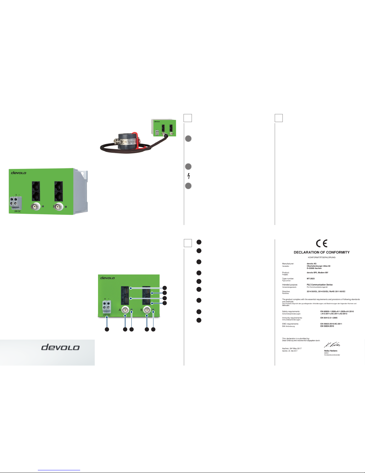
A BA BBEA EB
Versorgungsspannungsanschluss: hier verbinden Sie die Klemmen mit
den entsprechenden Leitern des Gleichstrom- Versorgungsnetzes.
BNC- Anschluss des Teilmodems A: hier verbinden Sie die BNCAnschlüsse mit der entsprechenden BNC- Speiseleitung des externen
Signalkopplers.
BNC- Anschluss des Teilmodems B: hier verbinden Sie die BNCAnschlüsse mit der entsprechenden BNC- Speiseleitung des externen
Signalkopplers.
Back- to Back- Verbindung Modem A: hier verbinden Sie, mit dem
beiliegenden RJ45-Patchkabel, die beiden Ethernetbuchsen CA und CB.
Back- to Back- Verbindung Teilmodem B: hier verbinden Sie, mit dem
beiliegenden RJ45-Patchkabel, die beiden Ethernetbuchsen CB und CA.
RJ45- Ethernetbuchse Teilmodem A: RJ45- Ethernetbuchse des
Teilmodems A zum Anschluss kompatibler Ethernet- Geräte über RJ45Ethernetkabel.
RJ45- Ethernetbuchse Teilmodem B: RJ45- Ethernetbuchse des
Teilmodems B zum Anschluss kompatibler Ethernet- Geräte über RJ45Ethernetkabel.
Kontrollanzeige des Teilmodem A: Leuchtet permanent GRÜN sobald
das Teilmodem A eine PLC- Datenverbindung hat.
Kontrollanzeige des Teilmodem B: Leuchtet permanent GRÜN sobald
das Teilmodem B eine PLC- Datenverbindung hat.
BPL Modem MV
MT: 2823
Installationsanleitung
Deutsch
devolo Service & Support – für Kunden in Deutschland
devolo-Produkte sind von höchster Qualität. Dazu gehört, dass Sie als Kunde in
der Lage sind, die devolo-Technologie optimal zu nutzen. Deshalb bietet devolo
umfassenden und lückenlosen Support für alle Benutzer. Wenn Sie also während der
Installation oder während des Betriebes Ihres devolo-Gerätes nicht weiterwissen,
bitten wir Sie, folgende Medien zu Rate zu ziehen:
• Handbuchistonlineabrufbarwww.devolo.de/BPL-Modem-MV-Handbuch
Sollten Sie noch keine Antwort auf Ihre Frage erhalten haben, wenden Sie sich bitte
an unsere Hotline.
Um eine schnelle und zielgerichtete Unterstützung zu gewährleisten, bitten wir Sie,
folgende Informationen für das Telefonat bereit zu halten: Produktname, Seriennummer (auf dem Gerätelabel), Firmware-Version, angeschlossene Endgeräte und
Problembeschreibung.
• Service-undSupport-Hotline
Bei Fragen zur Service- und Garantieabwicklung, Installation oder Konfiguration
Ihres devolo-Gerätes, wenden Sie sich bitte an unsere Service- und Support-Hotline
unter: +49 (0)241 99082 444 oder E-Mail: support@devolo.com
devolo AG
Charlottenburger Allee 60
52068 Aachen
Germany
Engineered in Germany www.devolo.de/smart
44655/0517
3
Diese Installationsanleitung beschreibt ausschließlich die nötigsten Installationsschritte. Weitere Informationen zur Konfiguration und zum Produkt finden Sie im
Produkthandbuch (www.devolo.de/BPL-Modem-MV-Handbuch).
Bestimmungsgemäßer Gebrauch
Bitte achten Sie auf einen bestimmungsgemäßen Gebrauch des devolo BPL Modem
MV, um Schäden an diesem oder anderen Geräten zu vermeiden. Der Bestimmungsgemäße Gebrauch des BPL Modem MV ist die Verbindung von Geräten im
Installationsbereich über Access Powerline Kommunikation. Das BPL Modem MV
ist zur Montage auf der Hutschiene vorgesehen. Das Gerät ist in Verbindung mit
einem Gleichstrom– Stromversorgungsgerät nach Überspannungskategorie 4 zur
Installation im Installationsbereich der Überspannungskategorie 4 oder niedriger
vorgesehen.
Wichtige Sicherheitsanforderungen
Einbau und Montage dürfen nur durch eine Elektrofachkraft und gem. NAV, Teil 2,
§ 13 auf Anweisung des Anlagenbetreibers erfolgen.
Die Leitungseigenschaften und Querschnitte zum Anschluss des BPL Modem MV
sind entsprechend der Absicherung vorzunehmen. Der Stromwert der Absicherung
soll 2 A betragen.
Montage
Montieren Sie das BPL Modem MV sachgemäß auf der Hutschiene. Beachten Sie
die vertikale Montage- Ausrichtung des BPL Modem MV, so dass die Stromzufuhr
von unten erfolgt und die Beschriftung aufrecht lesbar ist.
1
!
!
!
BB
CA
CB
DA
DB
EA
EB
BA
A
2
Anwendungsbeispiel mit induktivem MV-Koppler von Eichho.
Page 2

DB
CB
DA
CA
A BA BBEA EB
Supply voltage connection: Connect the terminals to the corresponding DC
current power supply conductors here.
Modem part A BNC connection: Connect the BNC connections to the corresponding BNC feed line of the external signal coupler here.
Modem part B BNC connection: Connect the BNC connections to the corresponding BNC feed line of the external signal coupler here.
Back to back connection for modem A: Connect both CA and CB Ethernet
jacks with the included RJ45 patch cables here.
Back to back connection for modem part B: Connect both CB and CA
Ethernet jacks with the included RJ45 patch cables here.
RJ45 Ethernet jack for modem part A: Modem part A RJ45 Ethernet jack for
the connection of compatible Ethernet devices over an RJ45 Ethernet cable.
RJ45 Ethernet jack for modem part B: Modem part B RJ45 Ethernet jack for
the connection of compatible Ethernet devices over an RJ45 Ethernet cable.
Modem part A control display: Illuminates steady GREEN as soon as the
modem part A has a PLC data connection.
Modem part B control display: Illuminates steady GREEN as soon as the
modem part B has a PLC data connection.
BPL Modem MV
MT: 2823
Installation Guide
English
devolo Service & Support – for customers in Germany
devolo products are of the highest quality. This includes making sure that you, the
customer, are able to take maximum advantage of devolo technology. Therefore
devolo provides comprehensive support for all users. So if you don‘t know how to
proceed when installing or operating your devolo device, please make use of the
advice in the following media:
• Themanualcanbeaccessedonlineatwww.devolo.com/BPL-Modem-MV-
manual
If you still haven‘t found an answer to your question, please use our hotline.
To ensure fast and ecient support, please have the following information ready
when you call: product name, serial number (on the device label), firmware version,
connected terminal devices and problem description.
• Service&Supporthotline
If you have questions concerning service and warranty processing, installation or
configuration of your devolo device, please call our Service and Support hotline at
+49 241 99082 444 or send an e-mail: support@devolo.com
devolo AG
Charlottenburger Allee 60
52068 Aachen
Germany
Engineered in Germany www.devolo.com/smart
44655/0517
3
This Installation Guide lists only the most basic installation steps that are necessary.
For additional information about configuration and the product, refer to the product
manual (www.devolo.com/BPL-Modem-MV-manual).
Intended use
Ensure that the BPL Modem MV is used according to its intended use in order to
prevent damage to it or other devices. The intended use of the BPL Modem MV is
to connect devices in the installation area via Access Powerline communication.
The BPL Modem MV is intended for installation on the DIN rail. The device, in
combination with a DC current power supply unit, is intended to be installed in
the installation area of the overvoltage category 4 or lower in accordance with
overvoltage category 4.
Important safety requirements
Installation may be performed by a qualified electrician and in accordance with
German Low Voltage Connection Ordinance (NAV), part 2, § 13 upon instruction of
the system operator.
The line properties and cross-sections for connecting the BPL Modem MV must
be selected based on the fuse protection. The current value of the fuse protection
should be 2 A.
Installation
Install the BPL Modem MV properly on the top-hat rail. Take into account the vertical installation alignment of the BPL Modem MV so that the mains power supply
comes from below and the label is legible in an upright position.
1
!
!
!
BB
CA
CB
DA
DB
EA
EB
BA
A
2
Example application with inductive MV coupler from Eichho.
 Loading...