

Page 1
P0051375
-
02 04/10
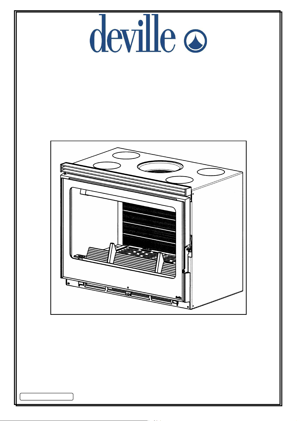
• FOYER / INSERT
• INSERT STOVE
• FEUERRAUM-EINSATZ
• FOCOLARE
• INSERT EMPOTRABLE
• FOGÃO INSERT
C0792
C07921
C0792C0792
1
11
• INBOUWHAARD
NOTICE D'INSTALLATION ET D'UTILISATION
INSTALLATION AND UTILISATION MANUAL
INSTALLATIONS- UND GEBRAUCHSANLEITUNG
INSTRUCCIONES PARA LA INSTALACION Y EL USO
ISTRUZIONI PER L’INSTALLAZIONE E L’USO
MANUAL DE INSTALAÇÃO E UTILIZAÇÃO
INSTALLATIE EN GEBRUIK
Page 2
FRANÇAIS ............................................................................................. p 3
ENGLISH................................................................................................ p 13
DEUTSCH .............................................................................................. p 23
ESPAÑOL .............................................................................................. p 34
ITALIANO............................................................................................... p 45
PORTUGUÊS......................................................................................... p 56
NEDERLANDSE...................................................................................... p 66
2
Page 3

SOMMAIRE
Pages
1 - DESIGNATION............................................................................................................................................. 4
2 - PUISSANCE CALORIFIQUE NOMINALE................................................................................................... 4
3 - DESCRIPTION ET ENCOMBREMENT....................................................................................................... 4
3.1 - Description
3.2 - Encombrement
4 - ENVIRONNEMENT ET ACCESSOIRES COMPLEMENTAIRES................................................................ 4
4.1 - Environnement
4.2 - Accessoires en option
4.3 – Raccordement électrique de la soufflerie
5 - CONDITIONS D’INSTALLATION DE L’APPAREIL.................................................................................... 5
5.1 - DENOMINATION DES DIVERSES PARTIES DU CIRCUIT D'EVACUATION DES FUMEES
5.2 - NATURE ET CARACTERISTIQUES DIMENSIONNELLES DU CONDUIT DE FUMEE AUQUEL
DOIT ETRE OBLIGATOIREMENT RACCORDE L'APPAREIL
5.2.1 - Nature du conduit de fumée
5.2.1.1 - Cas d'un conduit neuf
5.2.1.2 - Cas d'un conduit existant
5.2.2 - Section minimale du conduit
5.2.3 - Quelques préconisations générales
5.3 - NATURE ET CARACTERISTIQUES DU CONDUIT DE RACCORDEMENT ENTRE LE FOYER
ET LE CONDUIT DE FUMEE
5.4 - CONDITIONS DE TIRAGE
5.5 - VENTILATION DU LOCAL OU L'APPAREIL EST INSTALLE
5.6 - NATURE DES MURS ET DES PAROIS AVOISINANT L'APPAREIL
5.6.1 - Conseil de mise en oeuvre
5.6.2 - Cotes d'encastrement - Protection des parois et habillages en matériaux combustibles ou
se dégradant sous l'effet de la chaleur - Circuit de convection
5.6.2.1 – Disposition foyer
5.6.2.2 – Disposition insert
5.6.2.3 – Distribution d’air chaud
5.7 - PRECONISATIONS ET EXEMPLES D'INSTALLATION
5.7.1 - Installation dans une cheminée neuve à construire
5.7.2 - Installation dans un âtre existant bâti en matériaux réfractaires
normalement prévu pour un feu ouvert
5.8 - PREPARATION ET MISE EN PLACE DU FOYER DANS L'ÂTRE
5.8.1 - Opération générale à effectuer
6 - CONDITIONS D'UTILISATION DE L'APPAREIL........................................................................................ 9
7 - CONSEILS DE RAMONAGE ET D'ENTRETIEN DE L'APPAREIL ET DU CONDUIT DE FUMEE ........... 11
7.1 – Ramonage
7.2 – entretien maintenance du ventilateur
7.3 – entretien courant
8 - CONDITIONS GENERALES DE GARANTIE .............................................................................................. 12
5.8.2 - Mise en place de l’appareil
6.1 - Premier allumage
6.2 - Combustible
6.2.1 - Combustible recommandé
6.2.2 - Combustibles interdits
6.3 - Emploi des organes de manoeuvre et des accessoires
6.4 - Utilisation
6.4.1 - Allumage
6.4.2 - Fonctionnement
6.4.3 - Décendrage
6.4.4 - Règles de sécurité
6.4.5 - Soufflerie
3
Page 4
Nous vous conseillons de lire attentivement,
et au complet, le texte de la notice afin de tirer
le meilleur usage et la plus grande satisfaction
de votre appareil DEVILLE.
Le non respect des instructions de montage,
d'installation et d'utilisation entraîne la
responsabilité de celui qui les effectue.
CET APPAREIL DOIT ETRE INSTALLE
CONFORMEMENT AUX SPECIFICATIONS DES
D.T.U. EN VIGUEUR.
L’appareil doit être installé par un
professionnel qualifié.
Toutes les réglementations locales et
nationales, ainsi que les normes européennes,
doivent être respectées lors de l’utilisation de
l’appareil.
L’appareil ne doit pas être modifié.
1 - DESIGNATION
L’appareil est conforme aux exigences essentielles de
la directive 89/106/CEE Produits de Construction
suivant l’annexe ZA de la norme EN 13229.
C’est un appareil de chauffage continu à combustion
sur grille fonctionnant exclusivement au bois, à
chambre de combustion semi-fermée et conçu pour
être encastré dans une cheminée à construire ou dans
un âtre existant.
Relever le numéro de série de l’appareil inscrit sur la
plaque signalétique collée sur l’appareil et sur le
certificat de garantie, le noter dans la case ci-après :
N° de série
Celui-ci sera nécessaire pour identifier l’appareil lors
des demandes de pièces détachées.
Apapreil conforme à la Directive Compatibilité
Electromagnétique 89/336/CEE modifiée par la
directive 93/68/CEE.
2 - PUISSANCE CALORIFIQUE NOMINALE
Puissance
nominale
11 kW 12 Pa 8 g/s 324 °C
Puissance calorifique nominale en fonctionnement
continu : 11 kW.
. Obtenue sous un tirage de 12 Pa, au cours d’une
durée de feu de 1 heure, avec une charge de 4,5 kg de
bois dur non fendu (charme, chêne…) de 8 cm de
diamètre environ, soit 2 bûches.
. Pour obtenir ce régime de puissance, recharger sur
un lit de braises de 400 g environ soit 4,5 cm
d’épaisseur.
. La puissance annoncée est la puissance moyenne
obtenue au cours de cet essai de 1h, la tirette d’air en
position ouverture maxi.
Tirage Débit massique des
fumées
Température
des fumées
La combustion lente :
Obtenue sous un tirage de 6 Pa, la tirette d’air en
position fermée.
Recharger sur un lit de braises d’environ 0,3 kg (soit 3
cm d’épaisseur).
Durée supérieure à 3 heures avec une bûche de bois
dur non fendue de 3,5 kg.
Durée supérieure à 10 heures avec une ou 2 bûches
(privilégier les gros diamètres) de bois dur non fendues,
masse totale 10,5 kg.
Les conditions d’allure normale permettent l’obtention
d’une puissance maximale à ne pas dépasser pour
obtenir un fonctionnement en toute sécurité.
La charge maximum est de 15 kg de bois.
3 - DESCRIPTION ET ENCOMBREMENT
3.1 - Description
Les principaux éléments constituant votre appareil sont
indiqués et repérés sur la Fig. 1.
La chambre de combustion est en acier de 4 mm, le
fond du foyer est doublé d'une plaque d'âtre en fonte.
Une enveloppe en tôle ménage un circuit d'air de
refroidissement autour de la chambre de combustion et
protège les parois de la cheminée du rayonnement :
c'est un gage de sécurité et de performance.
La porte est en fonte, munie de joints qui assurent
l'étanchéité et permettent une grande autonomie de
fonctionnement.
La tirette de réglage, située en partie basse de la porte,
permet de choisir une allure de feu.
Une entrée d'air secondaire est réalisée autour de la
vitre de la porte pour la maintenir propre et assurer une
meilleure combustion du bois.
Une soufflerie à deux vitesses permet d’activer la
circulation de l’air chaud. Cet équipement vous permet
d’envoyer un flux d’air chaud dans 4 directions
différentes (pièces adjacentes). Non équipé de gaine
(s), il améliorera la convection dans la pièce où est
installée votre cheminée.
Débit de la soufflerie : 100 m³/h
Poids net de l’appareil
Poids nu (sans porte, déflecteur,
grille, plaque d’âtre)
C07921
109 kg
65 kg
3.2 - Encombrement (Fig. 2)
4 - ENVIRONNEMENT ET ACCESSOIRES
COMPLEMENTAIRES
4.1 - Environnement
Votre foyer-insert peut s'intégrer dans une cheminée
neuve DEVILLE.
4
Page 5
4.2 - Accessoires en option
L'appareil peut être équipé sur demande :
• De bouches de sortie d'air chaud ∅ 125 mm réf.
C07006.EU02 permettant de distribuer la chaleur
dans les pièces adjacentes (Fig. 3).
• Cet ensemble, fourni en option, doit être monté
avant l’installation du foyer dans la cheminée.
• Pour effectuer le montage, se reporter aux
indications de la notice jointe à cette option.
• D'un kit barbecue C07012.EA01 (Fig. 3).
4.3 - Raccordement électrique de la soufflerie
- L’appareil est livré avec un câble souple d’une
longueur d’environ 1,5m, permettant son raccordement
au réseau d’alimentation électrique. Son extrémité se
trouve au bas de la partie arrière gauche de votre insert
et il faudra le tirer (sans forcer) pour le sortir. Prévoir
sur l’installation fixe un dispositif de séparation
omnipolaire ayant une distance d’ouverture des
contacts d’au moins 3mm : ce dispositif permettra
d’isoler l’appareil du réseau d’alimentation électrique.
L’installation devra être conforme à la NFC 15100, en
particulier le branchement de la terre (fil vert et jaune)
devra être effectué.
- La puissance nominale de la soufflerie est de 19 W –
tension d’alimentation 230 V.
- Il peut être nécessaire d’extraire le ventilateur ou
l’insert de son logement : dans ce but réserver une
longueur de câble suffisante pour que ces opérations
puissent être effectuées sans provoquer de traction sur
le câble.
5 – CONDITIONS D’INSTALLATION DE
L’APPAREIL
L'installation ne devra pas être modifiée par l'utilisateur.
Nous rappelons ci-après les recommandations
élémentaires à respecter, celles-ci ne se substituent en
aucun cas à la stricte application de l'ensemble du DTU
24-2-2.
5.1 - Dénomination des diverses parties du
circuit d'évacuation des fumées (Fig. 4)
5.2 - Nature et caractéristiques
dimensionnelles du conduit de fumée auquel
doit être obligatoirement raccordé l'appareil
5.2.1 - Nature du conduit de fumée
5.2.1.1 - Cas d'un conduit neuf
Utilisation des matériaux suivants :
• Boisseaux de terre cuite conformes à la NF P
51-311.
• Boisseaux en béton conformes à la NF P 51-321.
• Conduits métalliques composites conformes aux
NF D 35-304 et NF D 35-303 ou ayant reçu un
Avis Technique favorable pour cet usage.
• Briques en terre cuite conformes à la NF P 51-
301.
• Briques réfractaires conformes à la NF P 51-302.
L'utilisation de matériaux isolés d'origine permet
d'éviter la mise en place d'une isolation sur le
chantier, notamment au niveau des parois de la
souche (résistance thermique minimale : 0,43 m²
k/W).
5.2.1.2 - Cas d'un conduit existant
L'installateur prend à son compte la responsabilité
des parties existantes. Il doit vérifier l'état du conduit
et y apporter les aménagements nécessaires pour
son bon fonctionnement et la mise en conformité
avec la réglementation.
Ramoner le conduit puis procéder à un examen
sérieux pour vérifier :
• La compatibilité du conduit avec son utilisation.
• La stabilité.
• La vacuité et l'étanchéité (annexe II du DTU 24-
1).
Si le conduit n'est pas compatible, réaliser un
tubage à l'aide d'un procédé titulaire d'un Avis
Technique favorable, ou mettre en place un
nouveau conduit.
5.2.2 - Section minimale du conduit
Réglementation
Boisseaux carrés ou
rectangulaires
Conduits circulaires
Fonctionnement
possible
portes ouvertes
Section minimale
4 dm²
Diamètre minimal
200 mm
Fonctionnement
portes fermées
Section minimale
2,5 dm²
Diamètre minimal
153 mm
Dans tous les cas, la section du conduit doit être au
moins égale à celle de la buse de raccordement sur
l'appareil.
5.2.3 - Quelques préconisations générales
• Un bon conduit doit être construit en matériaux
peu conducteurs de la chaleur pour qu'il puisse
rester chaud.
• L'habillage du conduit doit permettre de limiter la
température superficielle extérieure à :
- 50 °C, dans les parties habitables
- 80 °C, dans les parties non habitables ou
inaccessibles.
• Il doit être absolument étanche, sans rugosité et
stable.
• Il ne doit pas comporter de variations de section
brusques (pente par rapport à la verticale
inférieure à 45°).
• Il doit déboucher à 0,4 m au moins au-dessus du
faîte du toit et des toits voisins.
• Deux appareils ne doivent pas être raccordés sur
un même conduit.
5
Page 6
• Il doit déboucher dans la pièce où sera installé
l'appareil, sur une hauteur d'au moins 50 mm.
• Sa face intérieure doit être éloignée de 16 cm au
moins de tout bois et matière combustible.
• Les boisseaux doivent être montés partie mâle
vers le bas afin d'éviter le passage des coulures à
l'extérieur.
• Le conduit ne doit pas comporter plus de deux
dévoiements, c'est à dire plus d'une partie non
verticale :
- Si c'est un conduit maçonné :
L'angle des dévoiements ne doit pas excéder 45°
pour une hauteur totale du conduit limitée à 5 m.
Pour une hauteur supérieure, l'angle de
dévoiement est limité à 20°.
- Si c'est un conduit métallique isolé :
L'angle des dévoiements ne doit pas excéder 45°
avec une limitation de hauteur de 5 m entre le
haut et le bas du dévoiement. La hauteur totale
du conduit n'est pas limitée.
• L'étanchéité, l'isolation, les traversées de plafond
et plancher, les écarts au feu doivent être réalisés
dans le strict respect du DTU 24-2-2.
5.3 - Nature et caractéristiques du conduit de
raccordement entre le foyer et le conduit
de fumée
• Un conduit de raccordement doit être installé entre
l'appareil et le débouché du conduit de fumée.
• Ce conduit doit être réalisé à l'aide d'un tubage
polycombustible rigide ou flexible, justifiable d'un
Avis Technique favorable pour une desserte directe
de foyer fermé. A noter que sont interdits :
l'aluminium, l'acier aluminié et l'acier galvanisé.
• A noter que sont autorisés : la tôle noire (ép. Mini 2
mm), la tôle émaillée (ép. Mini 0,6 mm), l'acier
inoxydable (ép. Mini 0,4 mm).
• Ce conduit doit être visible sur tout son parcours
par une trappe ou grille de visite et ramonable de
façon mécanique (Fig. 5). Sa dilatation ne doit pas
nuire à l'étanchéité des jonctions amont et aval
ainsi qu'à sa bonne tenue mécanique et à celle du
conduit de fumée. Sa conception et, en particulier,
le raccordement avec le conduit de fumée doit
empêcher l'accumulation de suie, notamment au
moment du ramonage.
• Les jonctions avec l'appareil d'une part et le conduit
de fumée d'autre part doivent être réalisées dans le
strict respect du DTU 24-2-2 et des spécifications
du constructeur du tube, en utilisant tous les
composants préconisés (embouts, raccords, etc...).
5.4 - Conditions de tirage
• Le tirage est mesuré sur le conduit de
raccordement à environ 50 cm au-dessus de la
buse de l'appareil.
• Tirage nécessaire au bon fonctionnement porte
fermée :
- 6 Pa en allure réduite (0,6 mm de CE).
- 12 Pa en allure normale (1,2 mm de CE).
L’évaluation du tirage prévisible en fonction des
caractéristiques du conduit étant peu sûr, il est
recommandé d’installer systématiquement un volet
modérateur.
• Le modérateur permet d’obtenir un bon
fonctionnement du foyer, même dans des
conditions de tirages importants (conduits hauts,
tubage). Le modérateur doit être facilement visible
et accessible (Fig. 6).
• Le volet modérateur de tirage n'a pas d'influence
sur le fonctionnement de l'appareil lorsque la porte
est ouverte.
5.5 - Ventilation du local où l'appareil est
installé
• Le fonctionnement de l'appareil nécessite un apport
d'air supplémentaire à celui nécessaire au
renouvellement d'air réglementaire. Cette amenée
d'air est obligatoire lorsque l'habitation est équipée
d'une ventilation mécanique.
• La prise d'amenée d'air doit être située soit
directement à l'extérieur, soit dans un local ventilé
sur l'extérieur, et être protégée par une grille (voir
disposition conseillée Fig. 7).
A : FAVORABLE
Face sous vent dominant : favorise
l’écoulement de l’air frais et des fumées.
B : DEFAVORABLE
Face opposée au vent dominant.
• La sortie d'amenée d'air doit être située
directement dans la cheminée et déboucher le plus
près possible de l'appareil. Elle doit être obturable
lorsqu'elle débouche directement dans la pièce.
• La section d'entrée d'air doit être au minimum égale
au quart de la section du conduit de fumée avec un
minimum de :
- 70 cm² pour une utilisation uniquement porte
fermée.
- 200 cm² pour une utilisation possible porte
ouverte (pour certains foyers seulement : voir
notice d'utilisation).
• Il peut être nécessaire de stopper l'extracteur de la
ventilation mécanique pour éviter le refoulement
des fumées dans la pièce lors de l'ouverture de la
porte.
5.6 - Nature des murs et des parois avoisinant
l'appareil
5.6.1 - Conseil de mise en œuvre
Enlever tous les matériaux combustibles ou
dégradables sous l'action de la température, sur les
parois et à l'intérieur de celles-ci (sols, murs et
plafonds) à l'emplacement de la cheminée et du foyer.
6
Page 7
• L'habillage de l'appareil doit être réalisé avec des
matériaux incombustibles, classés MO.
• Le sol sera en matériaux incombustibles sous
l'appareil jusqu'à 400 mm au minimum de l'avant
de l'appareil.
• Lorsque le linteau est en matériau combustible
(poutre en bois, par exemple), il est nécessaire de
le protéger par un matériau incombustible, par un
déflecteur ou par le fronton (voir DTU 24-2-2 et
exemple Fig. 14).
• Si le mur d'adossement est une cloison légère ou
un mur avec une isolation combustible incorporée,
réaliser un doublage en matériaux incombustibles
(béton cellulaire de 10 cm avec une lame d'air de 2
cm sur toute la largeur de la cheminée avec un
débord de 5 à 10 cm).
5.6.2 - Côtes d'encastrement - Protection des parois
et habillages en matériaux combustibles ou se
dégradant sous l'effet de la chaleur - Circuit de
convection.
• Pour limiter l'échauffement des parois constituant
l'habillage à 65 K (K = degrés Celsius au-dessus de
la température ambiante), et obtenir un bon
fonctionnement de l'appareil, il est nécessaire de
respecter les dispositions ci-après.
• Par ailleurs, les dimensions minimales
d'encastrement indiquées garantissent l'accès aux
organes de manoeuvre, une course suffisante pour
les organes mobiles, l'accès et le démontage pour
les pièces susceptibles d'être remplacées.
• Cet appareil permet deux dispositions différentes
du circuit d'air de convection :
5.6.2.1 - Disposition Foyer :
• Elle correspond généralement à la construction de
la cheminée autour du foyer.
• L'air à chauffer emprunte 2 circuits différents (Fig.
8) :
- Le circuit 1 : intégré à l'appareil (double
enveloppe) avec entrée par l'avant d et sortie par
le haut b.
- Le circuit 2 : s'appuyant sur l'édifice avec entrée
par le bûcher f et entre le fronton et l'appareil c
et sortie par la hotte a.
-
Dans ce cas, les opérations à réaliser sont les
suivantes (Fig. 10) :
- Ouvrir les sorties d’air chaud prédécoupées sur le
dessus de la double enveloppe (A).
- Monter l’obturateur de sortie d’air chaud frontale
(B).
- Protéger les parois verticales (2 parois latérales,
l'arrière et la paroi frontale) par un isolant :
Laine de roche, conductibilité inférieure à 0,04
W/m °C, épaisseur 30 mm, recouverte d'une
feuille d'aluminium exposée au rayonnement du
foyer.
- Protéger le sol :
En posant l'appareil sur une plaque de ciment
fondu, conductibilité 2 W/m °C, épaisseur 40 mm,
écartée du sol de 80 mm.
• Respecter les dimensions minimales
d'encastrement et réaliser le circuit d'air de
convection, représentés sur la Fig. 11 (habillage à
construire autour du foyer).
• Mettre en place un faux plafond isolé (Fig. 17).
5.6.2.2 - Disposition Insert :
• Elle correspond généralement à la mise en place
de l'appareil dans une cheminée existante :
l'arrivée d'air à chauffer par le soubassement ou le
bûcher et la sortie d'air chaud par la hotte ne sont
pas réalisables.
• L'air à chauffer emprunte 2 circuits différents (Fig.
9) :
- Le circuit 1 : intégré à l'appareil (double
enveloppe) avec entrée par l'avant d et sortie par
l'avant e (les bouches de sortie d'air chaud par le
dessus b sont obturées).
- Le circuit 2 : s'appuyant sur l'édifice avec entrée
par les 2 côtés latéraux c et sortie par l'avant de
l'édifice a.
- Dans ce cas, les opérations à réaliser sont les
suivantes (Fig. 10) :
- Vérifier que l'obturateur de sortie d'air chaud
frontale est démonté (C) :
. Sortie d'air chaud par l'avant.
- Protéger les parois verticales (2 parois latérales et
l'arrière) par un isolant :
. Laine de roche, conductibilité inférieure à 0,04
W/m °C, épaisseur 30 mm, recouverte d'une
feuille d'aluminium exposée au rayonnement du
foyer.
- Le sol doit être constitué de briques ou béton
réfractaire :
. Conductibilité inférieure à 0,1 W/m °C, épaisseur
110 mm.
- Respecter les dimensions minimales
d'encastrement, représentées sur la Fig. 12.
5.6.2.3 Distribution d’air chaud :
Une distribution d’air chaud dans les pièces adjacentes
peut être réalisée :
• Retirer les obturateurs prédécoupés sur le dessus
du foyer, en perçant, à l’aide d’un foret de Ø 6, à
l’emplacement des 3 trous Ø 2 prévus à cet effet.
Remplacer les obturateurs par les buses Ø 125 de
sortie d’air chaud en option (Fig. 3).
• Mettre en place les plaques obturatrices sur la
double enveloppe du corps de chauffe.
7
Page 8
• Protéger thermiquement les passages de
distribution d’air chaud (16 cm au moins entre
gaine d’air chaud et matériaux combustibles) et
utiliser des gaines d’air chaud calorifugées. Les
matériaux choisis doivent avoir une excellente
tenue à la chaleur (classement MO).
ATTENTION :
Les gaines d’air chaud ne doivent pas toucher les
différentes parties du circuit d’évacuation des fumées et
encore moins transiter par le conduit de fumée.
• Partir de l’appareil en gaines verticales sur la plus
grande hauteur possible pour favoriser la
circulation par convection, limiter les longueurs de
gaines horizontales et le nombre de coudes.
• S’assurer de l’existence ou mettre en place un
circuit de « retour » d’air des pièces à chauffer vers
la pièce où est installé l’appareil. Veillez à ce que le
fonctionnement du circuit d’air chaud ne perturbe
pas le dispositif de ventilation de l’habitat.
• Il est important de s’assurer pendant le
fonctionnement que le débit d’air de « convection »
entre par les orifices d’entrée et sort par toutes les
bouches de sortie. Si ce n’est pas le cas, réduire la
section de la bouche qui fonctionne jusqu’à ce que
les autres bouches soufflent l’air chaud : l’utilisation
de sorties réglables permet de réaliser facilement
cet équilibrage.
• La plaque obturatrice, montée devant l’orifice de
sortie d’air en façade, peut être réglée de façon à
faire varier le débit des bouches d’air chaud ;
toutefois, elle préserve un passage d’air « de
sécurité » de 10mm : ceci permet d’éviter la
surchauffe de l’appareil lorsqu’aucune des 4
bouches Ø 125 n’est ouverte.
NOTA : Une fois la cheminée terminée, la température
superficielle des parois des locaux servant
d'adossement à la cheminée ne devra pas excéder
50°C en partie accessible (Fig. 13).
5.7 - Préconisations et exemples d'installation
L’appareil doit être installé sur un sol avec une capacité
portante suffisante. Si une construction existante ne
satisfait pas à cette condition préalable, des mesures
adéquates (par exemple, l’installation d’une plaque de
répartition de charge) doivent être prises pour
permettre au sol de supporter l’appareil.
5.7.1 - Installation dans une cheminée neuve à
construire
• La figure 17, donnée en exemple, représente la
mise en place dans une cheminée DEVILLE.
• Le mode de raccordement représenté est le plus
courant, soit :
- Raccordement sur conduit maçonné en attente
au plafond par élément spécial.
- D'autres possibilités existent : consulter le DTU
24-2-2
• Une sortie d'air chaud de 800 cm² de section
minimale doit être aménagée en façade ou sur les
côtés à au moins
300 mm du plafond pour évacuer
la chaleur et abaisser la température à l'intérieur de
l'ouvrage.
• Il peut aussi être prévu une sortie d'air dans la
pièce située derrière la cheminée ou à l'étage
au-dessus, voir paragraphe distribution d’air
chaud.
5.7.2 - Installation dans un âtre existant bâti en
matériaux réfractaires et normalement prévu
pour un feu ouvert
Raccordement côté cheminée (voir exemple Fig. 14) :
• Il est indispensable d'obturer de façon étanche la
base du conduit de fumée . Toute entrée d'air
dans celui-ci se fera au détriment du bon
fonctionnement de l'appareil.
• Effectuer un joint sur tout le pourtour de la
collerette en acier . Pour cela :
- Bloquer au mortier réfractaire la collerette .
- La partie supérieure de la couronne de mortier
sera en forme d'entonnoir.
• Mettre en place le tuyau de raccordement
dans la collerette scellée et faire en sorte qu'il
reste bloqué en position haute.
- L'extrémité du tuyau ne dépassera pas de la
collerette après emboîtement dans la buse
de l'appareil.
- Le tuyau de raccordement aura un diamètre au
moins égal à 153 mm.
Raccordement côté appareil :
• Placer l'appareil dans l'âtre (voir paragraphe
5.8) et procéder à l'emboîtement du tuyau sur la
buse de départ de l'appareil (Fig. 14).
- S'il y a un espace suffisant, engager le tuyau dans
la buse en passant les mains entre la partie
supérieure de l'appareil et la base de la collerette
.
- S'il n'y a pas suffisamment de place au-dessus de
l'appareil pour y passer les mains, l'engagement
du tuyau pourra se faire aisément en plaçant
préalablement dans ce morceau de tuyau, à une
dizaine de cm de sa base, une broche qui
permettra de se saisir du tuyau pour l'engager sur
la buse, en passant la main par l'intérieur de
l'appareil. Cette broche pourra rester en place
sans aucune gêne pour le fonctionnement (Fig.
15).
NOTA : Le tuyau de raccordement et la collerette
seront en acier inoxydable d'épaisseur mini 0,4 mm
• Les Figures 18 et 19, données en exemple,
représentent 2 cas courants d'installation :
8
.
Page 9

- Fig. 18 : Conduit existant, tubé.
Possibilité de sortie d'air chaud à travers l'avaloir et
la hotte existante.
- Fig. 19 : Conduit existant, conservé en l'état.
. La conception, l'état ou les dimensions de la
cheminée ne permettent pas de réaliser une sortie
d'air chaud à travers l'avaloir. L'air chaud sort
intégralement sous le fronton et la poutre.
. Une poutre en bois doit dans ce cas être
parfaitement protégée.
. La collerette maçonnée doit être réalisée le plus
bas possible.
. Les cotes d'encastrement de la Fig. 12 doivent
être respectées.
5.8 - Préparation et mise en place du foyer
dans l'âtre (Fig. 16)
5.8.1 – Opération générale à effectuer
Alléger le corps de chauffe pour faciliter son installation
dans l’âtre, pour ceci enlever la cale polystyrène
bloquant le déflecteur, ôter le déflecteur, les pièces
fonte qui sont à l’intérieur du foyer et la porte (voir
paragraphe 7.1 pour le démontage du déflecteur).
5.8.2 – Mise en place de l’appareil
Après avoir installé l'appareil dans la cheminée,
remettre en place toutes les pièces ôtées : pour cela
agir dans l'ordre inverse du démontage.
NOTA : Avant la mise en marche de l'appareil, enlever
les étiquettes autocollantes.
6 – CONDITIONS D’UTILISATION DE
L’APPAREIL
Ce "foyer fermé" est un véritable appareil de chauffage:
• Rendement élevé.
• Fonctionnement en allure réduite de longue durée.
6.1 - Premier allumage
• Après réalisation de la cheminée et mise en place
• Après le premier allumage (voir paragraphe
• Pendant les premières utilisations, une odeur de
6.2 - Combustible
6.2.1 - Combustible recommandé
de l'appareil, respecter le temps de séchage des
matériaux utilisés pour la construction (2 à 3
semaines).
6.4.1), faire un feu modéré pendant les premières
heures en limitant le chargement de l'appareil (une
bûche de ∅ 15 cm) avec la tirette d'air en allure
intermédiaire (Fig. 20) : montée en température
progressive de l'ensemble des éléments de la
cheminée et dilatation normale de l'appareil.
peinture peut se dégager de l'appareil : aérer la
pièce pour limiter ce désagrément.
Bois dur : chêne, charme, hêtre, châtaignier, etc... en
bûche de 50 cm de longueur.
Hauteur maximale de chargement : 20 cm.
Nous vous conseillons d'utiliser du bois très sec (20 %
d'humidité maximum), soit 2 ans de stockage sous abri
après la coupe, afin d'obtenir de meilleurs rendements
et d'éviter le bistrage du conduit de fumée et des vitres.
Eviter l'utilisation des bois résineux (pins, sapins,
épicéas...) qui nécessitent un entretien plus fréquent de
l'appareil et du conduit.
6.2.2 - Combustibles interdits
Tous les combustibles autres que le bois sont interdits,
notamment le charbon et ses dérivés.
Les flambées de petits bois, sarments, planchettes,
paille, carton sont dangereuses et à exclure.
L’appareil, ne doit pas être utilisé comme un
incinérateur à déchets.
6.3 - Emploi des organes de manoeuvre et des
accessoires
Poignée de porte : Elle doit être manœuvrée par
l’intermédiaire de la main froide.
Tirette de réglage d’air : Elle doit être manœuvrée par
l’intermédiaire de la main froide.
Main froide : elle sert à manœuvrer la tirette de réglage
d’air et la poignée de porte, et à extraire le cendrier.
Raclette : elle est utilisée pour le décendrage et sert à
arranger les bûches dans le foyer en fonction de
l’évolution de la combustion.
Ne vous brûlez pas les mains inutilement, servez-vous
des accessoires.
REGISTRE D’ALLUMAGE
La position Allumage est obtenue en manoeuvrant la
tirette directement avec la main : cette position ne doit
être utilisée que lorsque l’appareil est ‘’froid’’ et en
effectuant les opérations suivantes (Fig.20) :
• Opération n°1 :
Pousser la tirette de réglage d’air primaire vers la
droite jusqu’à la butée correspondant au
verrouillage de la ‘’Position Allumage’’.
• Opération n°2 :
Lever la tirette de réglage.
• Opération n°3 :
Maintenir la tirette en position haute et la pousser
vers la droite : vous êtes en ‘’Position Allumage’’.
Après l’allumage, pour revenir en position d’allure
normale, d’allure intermédiaire ou d’allure lente, utiliser
le tisonnier pour pousser la tirette de réglage d’air qui
peut être chaude.
6.4 - Utilisation
6.4.1 - Allumage
• Mettre la tirette d’air en position allumage (Fig. 20).
9
Page 10
• Placer sur la grille du papier froissé et du petit bois
très sec (brindilles), puis des branches de bois
fendues de section plus importante (∅ 3 à 5 cm).
• Enflammer le papier et refermer la porte (la laisser
légèrement entrouverte pour accélérer
l'embrasement en évitant le refoulement de fumée
hors de l’appareil).
• Lorsque la charge de "petit bois" est bien
enflammée, ouvrir la porte, charger l'appareil avec
le combustible recommandé.
6.4.2 - Fonctionnement
• L'allure désirée est obtenue en agissant sur les
organes de manoeuvre (Fig. 20) et en choisissant
une charge correspondant aux besoins.
• Pour obtenir une allure réduite de longue durée,
procéder au chargement sur un lit de braises à
peine rougeoyantes.
• Pour obtenir un embrasement rapide, relancer le
feu avec du "petit bois", effectuer le chargement,
maintenir éventuellement la porte entrouverte
pendant quelques minutes pour accélérer
l’embrasement, en gardant l’appareil sous
surveillance, puis fermer la porte. Cette opération
permet d’accélérer la reprise, notamment si le bois
est humide.
• Effectuer les changements d'allure (passage de
l'allure normale à l'allure réduite par exemple) avant
les rechargements, pendant la phase de
combustion des braises, pour permettre à l'appareil
et au conduit des fumées de changer
progressivement de régime.
• Pour éviter les refoulements des fumées et les
chutes de cendres dans la pièce, au moment des
rechargements, l’ouverture de la porte nécessite
plusieurs précautions :
- Arrêter le ventilateur pour éviter d’aspirer les
cendres qui risquent de tomber devant l’appareil.
- Entrouvrir la porte, marquer un temps d’arrêt
pour amorcer le tirage correspondant au
fonctionnement porte ouverte, puis ouvrir
lentement la porte.
• Le fonctionnement continu en allure réduite, surtout
pendant les périodes de redoux (tirage
défavorable) et avec du bois humide, entraîne une
combustion incomplète qui favorise les dépôts de
bistre et de goudron :
o Alterner les périodes de ralenti par des retours
en fonctionnement à allure normale.
o Privilégier une utilisation avec de petites
charges.
• Après un fonctionnement en allure réduite, la vitre
peut s'obscurcir à cause d'un léger bistrage. Ce
dépôt disparaît normalement en fonctionnement à
plus vive allure par pyrolyse.
• La chambre de combustion doit toujours rester
fermée, sauf lors du rechargement, afin d’éviter
tout débordement de fumée.
6.4.3 - Décendrage
• L'air utilisé pour la combustion du bois arrive sous
la grille lorsque la tirette d’air ouverte. Cet air
assure également le refroidissement de la grille.
Il est donc indispensable, pour obtenir les
performances optimales et éviter la dégradation de
la grille sous l'effet de la surchauffe, d'éviter son
obstruction en procédant régulièrement au
décendrage et à l'évacuation des cendres.
- La raclette permet d'effectuer le décendrage de
la grille (Fig. 1).
- Le cendrier, situé sous la grille, est facilement
extrait en le tirant à l'aide de la main froide.
• Le niveau des cendres ne doit jamais atteindre la
grille en fonte de l'appareil.
6.4.4 - Règles de sécurité
• Ne jamais jeter d'eau pour éteindre le feu.
• La vitre de l'appareil est très chaude : attention aux
risques de brûlures notamment pour les enfants.
• L'appareil dégage, par rayonnement à travers le
vitrage, une importante chaleur : ne pas placer de
matériaux, ni d'objets sensibles à la chaleur : à une
distance inférieure à 1,50 m de la zone vitrée.
• Vider le contenu du cendrier dans un récipient
métallique ou ininflammable exclusivement réservé
à cet usage. Les cendres, en apparence refroidies,
peuvent être très chaudes même après quelques
temps de refroidissement.
• Ne pas mettre en place des matériaux facilement
inflammables au voisinage de l'appareil et dans le
bûcher.
• En particulier, ne pas stocker de bois sous
l'appareil.
• En cas de feu de cheminée, mettre la tirette d’air
en position fermée.
6.4.5 - Soufflerie
- Utilisation (Fig. 21) :
Choisir une vitesse de ventilation :
Petite vitesse, sélecteur 13 en position I.
Grande vitesse, sélecteur 13 en position II.
Mettre l’appareil en chauffe.
Choisir le fonctionnement automatique (A) ou manuel
(M) avec le sélecteur 14.
En position M : marche et arrêt forcés du ventilateur.
Cette position permet un démarrage immédiat de la
soufflerie et nécessite un arrêt manuel.
En position A : marche automatique du ventilateur
quand l’ensemble de l’appareil est chaud,
généralement dans l’heure qui suit l’allumage. Son
fonctionnement est interrompu quand l’appareil est
froid, généralement à l’extinction du foyer.
Pour bénéficier à la fois d’un démarrage immédiat et de
l’arrêt automatique, utiliser la position M à l’allumage,
puis passer en position A une fois que l’appareil est
chaud. Il s’arrêtera alors automatiquement.
10
Page 11

7 - CONSEILS DE RAMONAGE ET
D'ENTRETIEN DE L'APPAREIL ET DU
CONDUIT DE FUMEE
7.1 - Ramonage :
Le ramonage mécanique du conduit de fumée est
obligatoire, il doit être réalisé plusieurs fois par an dont
une fois au moins pendant la saison de chauffe. Un
certificat doit être établi par l'entrepreneur.
A l'occasion des ramonages, il faudra :
• Procéder au démontage du déflecteur (Fig.23) :
- Démonter le déflecteur en le soulevant et en le
tirant vers l’avant.
- Laisser descendre la partie arrière du déflecteur
et le sortir.
- Pour remonter le déflecteur : agir dans l'ordre
inverse du démontage.
• Vérifier complètement l'état de l'appareil et en
particulier les éléments assurant l'étanchéité : joints
et organes de verrouillage, pièces d'appui (porte,
châssis).
• Vérifier l'état du conduit de fumée et du conduit de
raccordement : tous les raccords doivent présenter
une bonne tenue mécanique et avoir conservé leur
étanchéité.
• Nettoyez à l'aspirateur l'intérieur de la hotte pour
éviter l'accumulation de poussières ; dégager si
nécessaire le circuit de convection d'air chaud.
En cas d’anomalie : faire réparer l’appareil ou
l’installation par un professionnel.
7.2 – Entretien, maintenance du ventilateur
- Démontage de la soufflerie (Fig.22) :
Enlever les 2 vis de fixation de la soufflerie.
Sortir la soufflerie en tirant sur la grille.
-
Remontage de la soufflerie :
Agir dans l’ordre inverse du démontage.
- Plan électrique (Fig. 21)
7.3 – Entretien courant
• Nettoyer les vitres avec un chiffon humide et de la
cendre. Si c'est nécessaire, utiliser un produit de
nettoyage spécifique en respectant les instructions
d'utilisation : attendre que l'appareil soit
complètement refroidi pour procéder à cette
opération.
• Nettoyer régulièrement la réglette d’admission d’air
secondaire (Fig.24).
- Enlever à l'aspirateur les particules et
poussières qui sont coincées entre le guide d’air et
le verre. Si nécessaire glisser une fine lame ou
une feuille de carton rigide entre le guide d’air et
la vitre pour faciliter le nettoyage (déblocage des
particules).
Ces particules gênent la formation du film d'air
secondaire qui protège le vitrage du contact direct
avec les fumées et complète la combustion du
bois.
- Gratter avec l’extrémité d’un objet métallique
l’arrête inférieure de la réglette d’admission d’air
pour enlever le bistre qui a pu s’y agglomérer.
Ces opérations doivent être effectuées dès que le
verre est sale et impérativement après extinction
du foyer.
Si des traces de suies localisées et très marquées
(Fig.24) réapparaissent et se multiplient, il est
nécessaire de démonter le guide d'air pour
effectuer un décrassage plus complet (Fig.25) :
. Dégonder la porte et la poser à plat.
. Enlever les 3 vis.
. Enlever le guide d'air A et le nettoyer.
. Remonter l'ensemble et vérifier que le jeu de
vitrage préconisé est respecté.
Cette opération doit être effectuée par un
professionnel qualifié.
• Nettoyer régulièrement les grilles de sorties d’air
chaud de la hotte. Elles se colmatent d’autant plus
rapidement que leur maillage est fin : choisissez
une fréquence adaptée.
• Contrôler l'efficacité de la clenche de fermeture de
la porte et, si c'est nécessaire, effectuer les
réglages suivants (Fig. 26) :
- Durcir la fermeture de la porte :
. Procéder successivement par desserrage
de la vis et serrage de la vis .
. Agir par ¼ de tour sur les 2 vis et
recommencer l'opération si cela est
nécessaire.
NOTA : Cette opération augmente la pression du
joint d'étanchéité de la porte sur l'appareil.
- Assouplir la fermeture de la porte :
. Procéder successivement par desserrage
de la vis et serrage de la vis .
. Agir par ¼ de tour sur les 2 vis et
recommencer l'opération si cela est
nécessaire.
NOTA : Cette opération diminue la pression du
joint d'étanchéité de la porte sur l'appareil.
11
Page 12

8- CONDITIONS GENERALES DE GARANTIE
1. MODALITES
En dehors de la garantie légale, à raison des vices cachés, DEVILLE garantit le matériel en cas de vices apparents
ou de non-conformité du matériel livré au matériel commandé.
Sans préjudice des dispositions à prendre vis-à-vis du transporteur, les réclamations lors de la réception du
matériel sur les vices apparents ou la non-conformité, doivent être formulées auprès de DEVILLE par l’acheteur
dans les cinq jours de la constatation du vice par voie de lettre recommandée avec demande d’avis de réception. Il
appartient à l’acheteur de fournir toute justification quant à la réalité des vices ou des anomalies constatées.
L’acheteur doit, par ailleurs, laisser à DEVILLE toute facilité pour procéder à la constatation de ces vices ou
anomalies et pour y porter remède. De même l’acheteur doit tenir les matériels non conformes à la disposition de
DEVILLE, selon les instructions de cette dernière. Tout retour du matériel, pour quelque raison que ce soit, doit
faire l’objet d’un accord préalable formel de DEVILLE.
2. ETENDUE
La garantie de DEVILLE couvre, à l’exclusion de toute indemnité ou dommages-intérêts, le remplacement gratuit
ou la réparation du matériel ou de l’élément reconnu défectueux (hors pièces d’usure) par ses services à l’exclusion
des frais de main-d’œuvre, de déplacement et de transport.
Sur les appareils émaillés, les craquelures ne sont jamais considérées comme un défaut de fabrication. Elles sont
la conséquence de différence de dilatation tôle-émail ou fonte-émail et ne modifient pas l’adhérence. Les pièces de
rechange fournies à titre onéreux sont garanties six mois à partir de la date de facture ; toute garantie
complémentaire consentie par un revendeur de DEVILLE n’engage pas DEVILLE. La présentation du certificat de
garantie portant le cachet à date du revendeur DEVILLE est rigoureusement exigée lorsque la garantie est
invoquée. Ce certificat doit être présenté lors de la demande de réparation de l’appareil sous garantie, ou bien un
talon ou un volet détachable de ce certificat doit, selon l’organisation propre à DEVILLE, être retourné à celle-ci
dans les délais impartis. A défaut, la date figurant sur la facture émise par DEVILLE ne peut être prise en
considération. Les interventions au titre de la garantie ne peuvent avoir pour effet de prolonger celle-ci.
3. DUREE
La durée de la garantie contractuelle assurée par DEVILLE est de 2 ans (5 ans pour le corps de chauffe
foyers/inserts) à compter de la date d’achat de l’appareil par l’usager, sous réserve que les réclamations prévues
au titre des modalités ci-dessus aient été formulées dans les délais impartis. La réparation, le remplacement ou la
modification de pièces pendant la période de garantie ne peut avoir pour effet de prolonger la durée de celle-ci, ni
de donner lieu en aucun cas à indemnité pour frais divers, retard de livraison, accidents ou préjudices quelconques.
4. EXCLUSION
La garantie ne s’applique pas dans les cas suivants, sans que cette liste soit exhaustive :
Installation et montage des appareils dont la charge n’incombe pas à DEVILLE. En conséquence, DEVILLE ne peut
être tenue pour responsable des dégâts matériels ou des accidents de personne consécutifs à une installation non
conforme aux dispositions légales et réglementaires (par exemple l’absence de raccordement à une prise de terre ;
mauvais tirage d’une installation) ;
Usure normale du matériel ou utilisation ou usage anormal du matériel, notamment en cas d’utilisation industrielle
ou commerciale ou emploi du matériel dans des conditions différentes de celles pour lesquelles il a été construit.
C’est le cas par exemple du non-respect des conditions prescrites dans la notice DEVILLE : exposition à des
conditions extérieures affectant l’appareil telles qu’une humidité excessive ou variation anormale de la tension
électrique ;
Anomalie, détérioration ou accident provenant de choc, chute, négligence, défaut de surveillance ou d’entretien de
l’acheteur ;
Modification, transformation ou intervention effectuée par un personnel ou une entreprise non agréée par DEVILLE
ou réalisée avec des pièces de rechange non d’origine ou non agréées par le constructeur.
5. CONDITIONS PARTICULIERES DE GARANTIE
Ces conditions complètent et précisent les conditions générales de garanties ci-dessus et ont primauté sur cellesci, se reporter au feuillet ci joint « Conditions particulières de vente DEVILLE – Garantie ».
12
Page 13

CONTENT
Pages
1 - DESIGNATION............................................................................................................................................. 14
2 –NOMINAL CALORIFIC POWER.................................................................................................................. 14
3 - DESCRIPTION AND DIMENSIONS............................................................................................................. 14
3.1 - Description
3.2 - Dimensions
4 - ENVIRONNEMENT AND ADDITIONAL EQUIPMENT................................................................................ 14
4.1 - Environnement
4.2 – Optional equipment
4.3 – Electric connection of the blower
5- INSTALLATION REQUIREMENTS FOR THE APPLIANCE......................................................................... 15
5.1 - Definition of components included in the smoke evacuation system
5.2 Characteristics and size of the smoke flue to which the appliance must be connected
5.2.1 - Type of Smoke Flue
5.2.1.1 - New smoke flue
5.2.1.2 - Existing smoke flue
5.2.2 - Minimum Flue Section
5.2.3 - General Recommendations
5.3 - Type and characteristics of the pipe connecting the appliance to the smoke flue
5.4 – Draught requirements
5.5 – Ventilation of the area in which the appliance is to be installed
5.6 – Walls in the vicinity of the appliance
5.6.1 Installation advice
5.6.2 Building in dimensions – Protection of walls and casings made of combustible materials or which
are affected by heat – Convection system
5.6.2.1 – Stove Layout
5.6.2.2 – lnsert Layout
5.6.2.3 – Hot air distribution
5.7 - PRECONISATIONS ET EXEMPLES D'INSTALLATION
5.7.1 - Installation within a New Fireplace to be Built
5.7.2 - Installation in an existing fireplace built with refractory materials and initially made to be an open
hearth
5.8 - PREPARATION AND INSTALLATION OF THE APPLIANCE IN THE FIREPLACE
5.8.1 - General operations to be made
5.8.2 – setting up of the appliance
6 – USE REQUIREMENTS FOR THE APPLIANCE......................................................................................... 19
6.1 – First lighting
6.2 – Fuel
6.2.1 – Recommended fuels
6.2.2 – Forbidden fuels
6.3 – Use of the operation parts and equipment
6.4 - Use
6.4.1 - Lighting
6.4.2 - Working
6.4.3 – Ash removal
6.4.4 – Safety regulations
6.4.5 - Blower
7 – ADVICE ON CHIMNEY-SWEEPING AND STOVE AND SMOKE FLUE MAINTENANCE........................ 20
7.1 – Sweeping
7.2 –Maintenance of the ventilation system
7.3 – usual cleaning
8 – GLOBAL TERMS OF WARRANTY ............................................................................................................ 22
13
Page 14
You are advised to have a thorough and
careful reading of the instructions for use in
order to get the best use and satisfaction of
your DEVILLE appliance.
The fact of not respecting the fixing, the
installing and the use istructions involves the
responsibility of the person who doesn’t
respect them.
THIS STOVE MUST BE INSTALLED IN
ACCORDANCE TO THE CURRENT D.T.U.
SPECIFICATIONS..
The stove must be installed by a skilled
professional.
All the local and national regulations as well
as the European standards have to be
respected when the stove is used.
The appliance mustn’t be modified.
1 - DESIGNATION
The stove is in line with the essential requirements of
the directive 89/106/CEE Produits de Construction
according to the annexe ZA of the EN 13229 standard.
It is a continuous combustion heating appliance with
grate which exclusively works with wood with a semiclosed combustion chamber and which is designed to
be fitted in a chimney to be built.
Note down the serial number written on the descriptive
plate stuck on the appliance and on the certificate of
guarantee, write it down in the following box :
Serial number
This number will be necessary to identify your appliance
when spare parts will be needed.
Appliance is standard to the 89/336/EEC
Electromagnetic Compatibility Instruction modified by
the 93/68/EEC instruction.
2 – CALORIFIC NOMINAL POWER
Nominal
power
11 kW 12 Pa 8 g/s 324 °C
Nominal calorific power in continuous running : 11 kW.
. Obtained with a 12 Pa draught, in a one-hour burning,
with a loading of a piece of 4,5 kg of hard wood not
being split (oak, hornbeam…) of about 8 cm diametre,
that is to say 2 logs.
. To get this power rate, reload on an ash bed of about
0,4 kg that is 4,5-cm thick.
. The given power is the average power obtained during
a one-hour test, with the air intake damper opened at
its maximum.
The slow combustion :
Draught Smoke output /
weight
Smoke
temperatures
Obtained with a 6 Pa draught, with the air intake
damper in closed position.
Reload on an ash bed of about 0,3 kg that is 3-cm thick
It can last over 3 hours with 1 log of hard wood not split
with a total weight of 3,5 kg.
It can last over 10 hours with 1 or 2 logs (favour big
diametres) of hard wood not split of a total weight of
10,5 kg.
Normal speed conditions allow to get a maximum
power which is not to be exceeded to guarantee a
running in complete safety.
The maximum loading is 15 kg of wood
3 - DESCRIPTION AND DIMENSIONS
3.1 - Description
The main parts of your appliance are shown and
marked out on Fig. 1.
The combustion chamber is made of steel (4mm thick),
the bottom of the hearth is lined with a cast iron back
plate.
A metal sheet casing allows a cooling air flow around
the chamber of combustion and protects the walls of
the mantelpiece from radiance : it is a guarantee of
safety and performance.
The cast iron door is fitted with seals which ensure
smoketightness and allow a large autonomy of working.
The air damper, situated at the bottom of the door The
air damper, situated at the bottom of the door allows to
choose a fire speed.
An extra air intake is built in the upper part of the
window to keep it clean and ensure a better burning of
the wood.
A two-speed blower allows to activate the hot air
circulation. This equipment allows to send a hot air flow
in four different directions (adjoining rooms). Without
shaft, it will improve the convection where your
appliance is.
Blower output : 100 m³/h
Net weight of the appliance
Gross weight (without door,
deflector, grate, back plate)
C07921
109kg
65 kg
3.2 - Dimensions (Fig. 2)
4 – ENVIRONNEMENT AND ADDITIONAL
EQUIPMENT
4.1 - Environnement
Your hearth can fit in a new DEVILLE fireplace.
4.2 - Optional Equipment
The appliance can be fitted on demand with :
• Hot-air release vent ∅ 125 mm réf. C07006.EU02
allowing to supply heat in the adjoining rooms (Fig.
3).
14
Page 15
• This kit, provided as an optional equipment,
has to be fixed before the installation of the
appliance in the fireplace.
• To fix, refer to the instructions for use attached
to the option.
• A barbecue kit C07012.EA01 (Fig. 3).
4.3 – Electric connection of the blower
- The appliance is delivered with a 1.5-metre flexible
cable which allows its connection to the mains. Its end
is at the bottom of the left back part of your insert and
you’ll need to draw it (not too strongly) to get
it.Remember to put on the fixed installation an
omnipolar separation device with an opening distance
of the contacts of at least 3 mm : this device will ensure
the insulation of the appliance from the mains. The
installation will have to be in line with the NFC 15100,
especially the connection to earth (green and yellow
wire) will have to be done.
- The nominal power is the blower is 19 W –230 V
tension.
- It might be necessary to extract the vent or the insert
from their places: in this case keep a cable long enough
to do these operations without pulling too strongly on
the cable.
5 – INSTALLATION REQUIREMENTS FOR
THE APPLIANCE
The installation cannot be modified by the user.
We remind you hereafter of the prior recommendations
to be respected, these will have to be added to the strict
application of the whole DTU 24-2-2.
5.1 – Definition of components included in the
smoke evacuation system(Fig. 4)
5.2 – Characteristics and size of the smoke
flue to which the appliance must be
connected
5.2.1 - Type of Smoke Flue
5.2.1.1 - New Smoke Flue
Use of the following materials:
• Fireclay flue blocks compilant with French
Standard NF P 51-311
• Concrete flue blocks compliant with NF P 51-
321
• Composite metal pipes compliant with NF D 35-
304 and NF D 35-303 or which have received
"Avis Technique" approval (*) for this use
• Fireclay bricks compliant with NF P 51-301
• Refractory bricks compliant with NF P 51-302
The use of certified insulating materials means that
on-the-spot insulating work can be avoided,
particularly where the chimney stack is concerned
(minimum thermal resistance 0.43 m
2
k/W).
5.2.1.2 -
Existing Smoke Flue
The installer is responsible for existing parts. He
should check the condition of the flue and carry out
any work required in order to ensure that it is in
proper working order and compliant with the
regulations in force.
He should sweep the flue and then check the
following very thoroughly:
• Compatibility of the flue with the intended use ;
• Stability
• That the flue is empty and smoke-tight (DTU 24-
1, Appendix II).
If the flue is not compatible, make a casing using an
approved method ("Avis Technique" certificats (*) or
install a new flue.
(*) French assessment and certification system
5.2.2 – Minimum flue section
Réglementation
Square or oblong flue
blocks
Circular flues
Working with
Doors open
Minimum section
Minimum diameter
2
4 dm
200 mm
Working with
Doors closed
Minimum section
Minimum diameter
In all cases, the cross section of the pipe must be at
least equal to that of the connecting nozzle on the
appliance.
5.2.3 - General Recommendations
• A good flue will be built of materials with low heat
conducting properties so that it stays hot.
• Flue casing should be such as to limit the external
surface temperature to the following :
- 50°C in living areas
- 80°C in non-living or inaccessible areas
• lt should be completely smoke-tight, stable and
have no rough spots.
• There should be no sudden changes in section
(slope in relation to the vertical less than 45°).
• It should extend at least 0,4 m above the ridge of
the roof and of adjacent roofs.
• Two appliances should not be connected to the
same flue.
• It should come out into the room containing the
appliance at a height of at least 50 mm.
• The interior face should be at least 16 cm away
from any wood or combustible materials.
• Flue blocks should be placed with the male part
towards the bottom so as to avoid any leaks to the
outside.
• The flue should include no more than two changes
of direction, i.e. no more than one non-vertical
section.
15
2,5 dm
153 mm
2
Page 16
- If the flue is in masonry :
The bend angle should not exceed 45° over a total
flue height limited to 5 m. For any greater height,
this angle should not exceed 20°.
- If it is an insulated metal flue :
The bend angle should not exceed 45° with the
height limited to 5 m between the top and bottom
of the bend. There is no limitation as to total flue
height.
• Smoke-tightness, insolation, openings in walls or
floors and sale fire distances should all strictly
comply with the provisions of DTU 24-2-2.
5.3 – Type and characteristics of the pipe
connecting the appliance to the smoke
flue
• A connecting pipe must be installed between the
appliance and the smoke flue outlet.
• The pipe should consist of an "Avis Technique"
approved rigid or flexible multi-fuel tube designed to
be used directly with a closed fireplace. lt should be
noted that the following are forbidden : aluminium,
aluminium steel and galvanized steel ;
• The following are approved : black plate (min.
thickness 2 mm), enamelled plate (min. thickness
0,6 mm) and stainless steel (min. thickness 0,4 mm
• The flue must be visible over its whole length
through a grille or inspection flap and be able to be
swept by mechanical means (Fig. 5). Any
expansion should not adversely affect the smoketightness of the joins at either end or its mechanical
performance or that of the smoke flue. lts design,
and more especially the connection between it and
the smoke flue, should be such as to prevent the
accumulation of soot, particularly when it is being
swept.
• Connections to the appliance and the flue should
strictly comply with DTU 24.2.2 and with the
specifications of the pipe ; they should include all
the recommended parts (end pieces and all other
fittings).
5.3 – Draught conditions:
• Draught is measured on the connecting pipe at a
point approximately 50 cm above the outlet on the
appliance.
• The following draught is required for proper working
with the door closed :
- 6 Pa at reduced speed (0,6 mm WG)
-12 Pa at normal speed (1,2 mm WG)
As there is always some doubt as to any evaluation
of the possible draught depending on flue
characteristics, it is advisable to systematically
install a damper.
• The damper ensures that the appliance works
properly, even when the draught is considerable
(high flue, piping). It should be readily visible and
accessible (Fig. 6).
• The damper does not affect stove performance
when the door is open.
5.5 - Ventilation of the local area in which the
appliance is to be installed
• The appliance needs air in addition to the air
required by the statutory air change rate. This is
obligatory when the dwelling includes mechanical
ventilation..
• The air intake should give directly to the outside or
should be located in an area ventilated to the
outside ; it should also be protected by a grille (see
advised layout ( Fig. 7).
A : FAVOURABLE
Face in prevailing wind , favour the flow of fresh
air and smokes:
B : UNFAVOURABLE
Face opposite prevailing wind.
• The air intake outlet should be located directly in
the fireplace and come out as near as possible to
the appliance.The user should be able to close it off
when it comes out directly into the room.
• The air intake section should be at least equal to
one-quarter of the section of the smoke flue with a
minimum of :
- 70 cm2 for use with the door closed only
- 200 cm2 for use with the door open or closed (For
certain appliances only : see user's manual).
• It may be necessary to stop the extractor of the
mechanical ventilation so as to avoid smoke
coming back into the room when the door is
opened.
5.6 – Walls in the vicinity of the appliance
5.6.1 - Installation advices
Remove all materials that are either combustible or
affected by temperature from walls and inside elements
(doors, walls and ceilings) near the chimney and the
fireplace.
• The appliance should be encased in MO-rated
incombustible materials.
• The floor should be of incombustible material from
under the appliance to at least 400 mm in front of
the appliance.
• If the mantelpiece is made of a combustible
material (a wooden beam, for example), it must be
protected by some sort of incombustible material,
by a deflector or by the fascia (see DTU 24-2-2 and
Fig. 14
).
16
Page 17
• If the supporting wall is a light partition wall with
combustible built-in insolation, it must be lined with
incombustible material (10 cm cellular concrete
with a 2 cm cavity across the whole with of the
fireplace extending 5 to 10 cm each side).
5.6.2 Building-in Dimensions - Protection of Walls
and Casing made of Combustible Materials or
which are affected by Heat - Convection
System
• To limit overheating of the casing walls to 65 K (K =
°C above ambient temperature) and obtain the best
performance from the appliance, the instructions
below should be followed.
• Further, the minimum building-in dimensions shown
ensure access to the control components, sufficient
travel for the moving parts, plus access to and
removal of any parts that need to be replaced.
• There are two possible layouts for the convection
system :
5.6.2.1 -
Stove Layout
:
• This usually concerns the construction of a
fireplace around the appliance.
• The air to be heated can take two different paths
(Fig. 8) :
- Circuit 1: incorporated into the appliance (double
casing) with intake at the front d and exit via the
hot air vents b.
- Circuit 2 : supported by the structure with intake
via where the wood is stored f and between the
fascia and the appliance c and exit via the
extractor hood a.
-
ln this case, proceed as follows (Fig. 10) :
- Open both hot air outlets cut out on the top of the
double casing (A).
- Install the front hot air outlet plug (B).
- To protect the vertical walls (2 side walls, one rear,
wall), insulate them using :
Rock wool, conductivity inferior to 0,04 W/m°C, 30
mm thick, covered with aluminium foil exposed to
the heat from the appliance.
- Floor protection :
Stand the appliance on a base plate of high
alumina cement, conductivity 2 W/m °C, thickness
40 mm, 80 mm from the floor.
• Ensure the minimum embedding dimensions and
put in the convection system, as shown in Figure
11 (casing to be built around the stove).
• Put up the insulated false ceiling (Fig. 17).
5.6.2.2 -
Insert Layout
• This usually concerns the installation of an
appliance within an existing fireplace : the intake of
air to be heated via the base or the wood store, and
air exit through the extractor hood are not possible.
• The air to be heated can take two different paths
(Fig. 9)
:
- Circuit 1 : incorporated into the appliance
(doublecasing) with intake at the front d and exit
via the front e (the hot air outlet vents b above
are closed off).
- Circuit 2 : supported by the structure with intake
via the two sides c and exit via the front a .
- In this case, proceed as follows (Fig. 10) :
- Make sure the front hot air outlet plug has been
removed (C) :
. Hot air exit via the front.
- To protect the vertical walls (2 side walls, one rear
wall), insulate them using :
. Rock wool, conductivity inferior to 0,04 W/m°C, 30
mm thick, covered with aluminium foil exposed to
the heat radiated by the appliance.
. Conductivity inferior to 0,1 W/m °C, thickness 110
mm.
-
Ensure the minimum embedding dimensions
shown in Fig. 12.
5.6.2.3 Hot air distribution :
A hot air distribution can be made in the adjoining
rooms :
• Remove the precut shutters above the appliance
use a Ø 6 drill through the three marked holes (Ø 2)
made for the purpose. Replace the shutters with
the nozzles (Ø 125) of hot air release suggested as
optional equipment (Fig. 3).
• Put in place the shutter plates on the double lining
of the heating body.
• Provide a heat protection to the hot air release
paths (16 cm at least between the hot air pipe and
the combustible materials) and use hot air heatinsulating pipes. The chosen materials must have a
good heat-resistance (MO reference).
CAUTION :
The hot air release pipes must not be in contact with
the different parts of the smoke evacuation circuit and
must not pass through the smoke pipe.
• Start from the appliance with pipes of the longest
height possible to favour the flow by convection,
limit horizontal pipes and bends.
• Make sure there is a ‘back‘ circuit of air coming
from the rooms to be heated to the rooms where
the appliance is set (if there isn’t,put one in place).
Pay attention that the working of the hot-air circuit
doesn’t disrupt the ventilation device of the house.
17
Page 18
• It is important to make sure that during the working
of the appliance the ‘convection’ air output enters
the inlet port and goes out from all the outlet ports.
If it is not the case, reduce the section of the
working port until the other ports blow hot air : the
use of adjusting ports allows to make this balance
easy.
• The shutter plate mounted before the outlet port at
the front can be adjusted in order to vary the outlet
of the hot air port, yet it keeps a ‘safety’ air path of
10 mm : it avoids the overheating of the appliance
when none of the four ports (Ø 125) are open.
NOTA : Once the fireplace is finished, the superficial
temperature of the walls of the house against which the
fireplace is put must not exceed 50°C on accessible
parts (Fig. 13).
5.7 – Recommendations and installation
examples
The appliance must be set up on a floor with a sufficient
bearing capacity. If the existing construction does not
comply with this prior requirement, appropriate
measures must be taken to allow the floor to bear the
appliance, such as setting up a load distribution plate.
5.7.1 - Installation within a New Fireplace to be Built
• Fig 17 shows installation within a DEVILLE
fireplace.
• The connection method shown is the most
common one :
- Connection to a masonry flue connected to the
ceiling by a special fixing device.
- Other possibilities exist : see DTU 24-2-2.
• A hot air outlet with a minimum section of 800 cm2
should be installed at the front or sides, at least
300 mm from the ceiling, to expel the heat and
reduce the inside temperature of the structure..
• A hot-air release vent can also be installed in
the room behing the fireplace or upstairs on the
room above see paragraph hot-air distribution.
5.7.2 - Installation in an existing fireplace built with
refractory materials and initially made to be
an open hearth
Connection with the chimney (see example Fig. 14) :
• It is necessary to smoke-tight obstruct the base
of the smoke flue . Any air coming in will
hamper the good running of the appliance.
• Make a seal on the whole circumferenceof the
steel collar . To do so :
- Block with refractory mortar the collar .
- The upper part of the mortar crown will be
funnel-shaped.
• Place the linking pipe in the sealed collar so
that is kept in high position.
- The end of the pipe mustn’t go beyond the
collar after the fitting with the nozzle of the
appliance.
-The linking pipe will have a diametre al least
equal to 153 mm.
Connection with the appliance:
• Place the appliance in the hearth (see
paragraph 5.8) and fit the pipe on the original
nozzle of the appliance (Fig. 14).
- If the space is big enough, insert the pipe in the
noozle placing the hands between between the
upper part of the appliance et the base of the collar
.
- If there is not space enough above the appliance to
place there the hands, the insertion of the pipe can
be done easily in putting first in this piece of pipe at
about ten centimetres from its base a broach
which will allow to seize the the pipe to insert it on
the noozle passing the hand from the inside of the
appliance. This broach can stay there without
hampering the working of the appliance (Fig. 15).
NOTA : The connecting pipe and the collar will
have to be made of stainless steel with a minimum
thickness of 0,4 mm .
• The sketches 18 and 19, given as example,
represent 2 cases of common installations:
- Fig. 18 : Existing pipe, lined.
Possibility of hot air release through the head and
the existing hood.
- Fig. 19 : existing pipe, kept as it is.
. The design, condition or sizes of the chimney do
not allow to a hot air release through the chimney
head. The hot air goes out fully under the pediment
and the beam.
. A wooden beam has then to be completely
protected in that case.
. The masonry collar has to be built the lowest
possible.
. The built-in fitting measures of the Fig. 12 have to
be respected.
5.8 - Preparation and placing of the appliance i
the hearth (Fig. 16)
5.8.1 –General Operation to be made
Lighten the heating body to make it easy its installation
in the fireplace, to do so remove the polystyrene
wedges holding the deflector, take of the deflector, the
cast iron parts that are inside the appliance and the
door (see paragraph 7.1 to dismount the deflector).
5.8.2 – Setting up of the appliance
Once the appliance installed in the fireplace, put back
all the removed parts: to do so proceed in the reverse
order of the dismounting.
: Before the switching on of the appliance,
NOTA
remove the stickers.
18
Page 19

6 –
USE REQUIREMENTS FOR THE
APPLIANCE
This ‘closed appliance’ is a real heating appliance:
• High output.
• Slow speed running for a long period of time.
6.1 - First lighting
• After the building of the fireplace and the setting up
of the appliance, a drying period of the materials
used for the work has to be respected (2 to 3
weeks).
• After the first lighting (see paragraph 6.4.1), make
a moderate fire in the first hours limiting the loading
in the appliance (a log of ∅ 15 cm) with the air
intake damper in an intermediate position (Fig.
20) : progressive rise in temperature of all the
elements of the fireplace and normal expansion of
the appliance.
• During the first uses, a paint odor can come out
from the appliance : ventilate the room to limit this
inconvenience..
6.2 - Fuel
6.2.1 – Recommanded fuel
Hard wood : oak, hornbeam, beech, chestnut tree, etc...
in log of 50 cm long.
Maximum loading height: 20 cm..
We recommend you to use very dry wood (20 %
maximum humidity), that is a 2-year store under shelter
after cutting, to get better outputs and to avoid the
darking of the smoke flue and of the windows.
Avoid the use of conifers (pines, firs, spruces...) which
ask for a more frequent cleaning of the appliance and
the flue.
6.2.2 – Forbidden fuels
All fuels except wood are forbidden, especially coal and
its by-products.
Fires with twigs, twinings, small boards, straw,
cardboard are dangerous and banned.
The appliance must not be used as a waste incinerator.
6.3 - Use of the operation parts and equipment
Door handle : it must be handled thanks to the cold
hand.
Air intake control lever : it must be handled thanks to
the cold hand.
Cold hand : it is used to handle the pull knob of the air
control, and the door knob. It is also used to pull out the
ashtray.
Scraper
the fireplace according to the combustion.
: it is used to remove and to arrange the logs in
Do not burn your hands uselessly. Use the accessories.
LIGHTING DAMPER
The lighting postion is obtained through moving the
damper directly with the hand : this position can only be
used when the appliance is ‘cold’ and in making the
following operations (Fig.20) :
• Operation n°1 :
Push the primary air adjutment damper to the right
up to a stop which corresponds to the locking of
the‘lighting position’.
• Operation n°2 :
Lift the air intake damper.
• Operation n°3 :
Maintain the damper in its high position and push it to
the right : you are in ‘ lighting position’.
After the lighting, to come back to normal speed
position, intermediate speed or slow speed, use the
poker which can be hot to push the damper.
6.4 - Use
6.4.1 - Lighting
• Put the air intake damper in lighting position (Fig.
20).
• Place crumpled paper and small and very dry parts
of wood (twigs) on the grate, then place branches
of split wood of a bigger size (∅ 3 à 5 cm).
• Light the paper and shut the door (leave it slightly
open to accelerate the lighting in avoiding any
blowing back outside the appliance).
• When the loading of small parts of wood is well lit,
open the door, load the appliance with the
recommended fuel .
6.4.2 - Working
• The wanted speed is obtained in moving the
different components (see Fig. 20) and in choosing
a load corresponding to the needs.
• To get a slower speed for a longer period, load on a
hardly glowing bed of embers.
• To get a rapid blaze, restart the fire with small parts
of wood, load with logs, possibly maintaining the
door slightly open for a few minutes to accelerate
the blaze, keeping the appliance under
surveillance, then close the door. This operation
allows to accelerate the restart, especially if the
wood is humid....
• Adjust the speed changes (going from a normal
speed to a slower speed for example) before
loadings in the embers’combustion stage, to let the
appliance and the smokes’ flue progressively
change speed.
• In order to avoid smoke blowing back and falling
down of the ashes in the room when you reload, the
opening of the door needs to take a few
precautions :
19
Page 20
- Stop the ventilation in order to avoid vacuuming
the ashes that might fall before the appliance
- Open slightly the door, pause for a moment to
start the draught corresponding to the running with
a open door, then slowly open the door.
• The continuous running with a slow speed,
especially in milder weather (unfavourable draught)
and with humid wood, leads to an incomplete
burning which favour bistre and tar deposits:
o Alternate slow speeds with some returns to
normal speed running period.
o Favour uses with small loads...
• After a running with a slow speed , the window can
get dark because of a slight bistre. This deposit
normally disappearsCe dépôt disparaît in a higher
speed pyrolysis running.
• The combustion chamber must be always closed
except when reloading in order to avoid any excess
of smoke.
6.4.3 -
Ash removal
• The air used for the combustion of wood comes
from under the grate when the air intake damper is
open. This air also ensures the cooling of the grate.
It is therefore necessary to get optimal
performances and to avoid damage of the grate
under the the effect of overheating, it is also
necessary to avoid its obstruction in proceeding in
regular ash removal and the clearing of the ashes..
- The scraper allows to make the ash removal of
the grate (Fig. 1).
- The ashtray- fixed under the grid - is easily
removable by pulling it out thanks to the cold
hand.
• The level of the ashes must never reach the cast
iron grate of the appliance.
6.4.4 - Safety regulations
• Never throw water to put the fire out.
• The window of the appliance is very hot : be careful
you don’t get burnt notably children.
• The appliance gives out important heat through
radiation : don’t put materials nor heat-sensitive
objects within a distance inferior of 1,50 m to the
window.
• Empty the content of the ash pan in a metallic or
inflammable container kept for this use only. The
ashes which look like cold can actually be very hot,
even after some cooling time.
• Don’t place easily inflammable materials in the
environment of the appliance and in the place
where you store wood.
• Particularly, don’t store wood under the appliance
• In case of a chimney fire, put the air intake damper
in a closed position.
6.4.5 - Blower
- Use (Fig. 21) :
Choose a ventilation speed :
Small speed, selector 13 in position I.
Big speed, selector 13 in position II.
Let the appliance heat.
Choose the automatic running (A) or manual (M) with
the selector 14.
In M position : forced on and off of the vent. This
position allows a immediate starting of the blower and
asks for a manual stop.
In A position : automatic working of the vent quand
when the appliance is completely hot, generally in the
hour that follows the lighting. Its running is stopped
the appliance is cold, generally at the extinction of the
fire.
To enjoy both the immediate starting and the automatic
stop, use the M position at the ligting stage, then
change to A position once the appliance is hot. It will
stop automatically in that case.
7 - ADVICE ON CHIMNEY-SWEEPING AND
STOVE AND SMOKE FLUE MAINTENANCE
7.1 - Sweeping:
The mecanical sweeping of the smoke flue is
compulsory, it has to be made a few times a year and
one sweeping has to done during the heating period. A
certificate has to be established by the professional.
For sweepings, you’ll need to:
• Remove the deflector (Fig.23) :
- Dismantle the deflector by lifting it and drawing
if forward.
- Let the back part of the du deflector go down
and take it out.
- To put the deflector back: proceed in the reverse
way of the dismantling.
• Check thoroughly the condition of the appliance
paying special attention to smoke-tightness
elements : seals and locking components, support
parts (door, frame).
• Check the condition of the smoke flue and the
connecting pipe : all the connections must show
good mecanical holding and must have kept their
smoke-tight features.
• Vacuum the inside of the hood to avoid any
accumulation of dust ; clear if necessary the hot air
convection route..
If you detect any irregularities : have your appliance or
your installation repaired by a professional.
7.2 – Cleaning , maintenance of the vent
20
- Dismantling of the blower (Fig.22) :
Remove the 2 screws from the fixing of the
blower.
Take out the blower in drawing the grate.
-Reassembling of the blower:
Proceed in the reverse way of the dismantling.
- Electric plan (Fig. 21)
Page 21
7.3 – Usual cleaning
• Clean the window with a wet cloth and ash. If
necessary use a specific cleaning product
respecting the instructions for use : start the
cleaning once the appliance is completely cold.
• Clean regularly the secondary air intake part
(Fig.24).
- Vacuum dust and the particles stuck between
the air guide and the window glass. If necessary
slip a thin blade or a sheet of rigid cardboard
between the air guide and the glass to make the
cleaning easier (clearing of the particles).
These particles block the making of the secondary
air flow which protects the widow from the direct
contact with smokes and complete the the burning
of the wood.
- Scrape off with the end of a metallic object the
inferior edge of the air intake part to remove the
bistre which has settled there.
These operations have to be made as soon as the
window glass is dirty and it is essential to wait for
the complete extinction of the fire within the
appliance to implement them.
If some local and distinct soot patches (Fig. 24)
appear again and multiply, it is necessary to
dismount the air guide to make a more complete
cleaning (Fig. 25) :
This operation has to be performed by a skilled
professional.
• Clean regularly the hot air releases grilles of the
hood.They get filled in all the more easily as their
meshing is thin : choose a suitable frequency of
cleaning.
• Check the efficiency of the latch of the door and if
necessary make the following adjustments (Fig.
26) :
- Harden the closing of the door:
- Loosen the closing of the door:
. Hang the door out and lay it down.
. Remove the 3 screws.
. Remove the air guide A and clean it.
. Reassemble the whole and check that the
original window kit is respected.
. Proceed successively through the loosening
of the screw and the screwing down of .
. Give the 2 screws a quarter turn and do it
again if necessary.
NOTA : This operation increase the pressure on
the smoke-tight seal of the door of the appliance.
. Proceed successively through the loosening
of the screw and the screwing down of .
. Give the 2 screws a quarter turn and do it
again if necessary.
NOTA : This operation decrease the pressure on
the smoke-tight seal of the door of the appliance.
21
Page 22
8 - GLOBAL TERMS OF WARRANTY
1. TERMS AND CONDITIONS
Apart from the legal warranty, particularly for latent defects, Deville guarantees to deliver the furniture in case of
obvious defects or non-conformity to the ordered furniture.
Without prejudice to the provisions that are to be taken concerning the carrier, claims on delivery of furniture
concerning the obvious defects or the non conformity, must be issued by the Buyer in writing a registered letter
with confirmation of receipt to Deville company with in 5 days after noticing the defect. It is up to the Buyer to prove
the reality of the noticed defects and irregularities. The Buyer must let Deville every opportunity of noticing any of
those defects and irregularities in order to salve then.
The Buyer must also keep the non standard supplies at the disposal of Deville, according to the instructions of the
latter. Prior to any return of supplies an agreement will be issued.
2. EXTEND
The warranty of Deville covers, except for any compensation or for damages, the free replacement or repairing of
supplier the part acknowledged as being defected (except for wear and tear parts ) by its services to the exclusion
of the fees for the workplace, for the removal and for the shipping.
On enamelled equipments, appliances, crackles are never considered as a manufacturing defect. They are due to
the difference of expansion of iron enamel or cast-iron enamel and don’t alter the adherence.
Paid replacement parts are warranted for a six-month period from the invoicing date, any additional warranty
agreed by a retailer from Deville doesn’t commit Deville. Whenever claiming under a warranty, the guarantee with
the stamp from the retailer Deville is strictly required. The above guarantee must be produced for any demand to
repair the appliance under warranty, or a detachable slip or coupon of any such guarantee must, according to the
own organisation of Deville, be returned to the latter within the required time. For lack of this, the date on the
invoice issued by Deville can’t be taken into account. The interventions under warranty can’t have the effect of
continuing the warranty.
3. WARRANTY PERIOD
The agreed warranty period assured by Deville is the longer of 2 years (5 year for the heating body / insert and
stove) from the day of the purchase of the appliance, subject to the above terms and conditions are fact that the
claims covered by the conditions are requested within the required time. The repairing, the replacement or the
alteration of parts under the warranty period can neither have the effect of continuing the period of the latter, not
get to any compensation for any fees, for late delivery, accidents or any such damages.
4. EXCLUSION
The warranty is unavailable for the following cases, without this list being exhaustive :
- Fitting out, fitting out and assembling of appliances not due to Deville.
- Consequently Deville can’t be considered as responsible for damages or supplies, or accidents to persons due
to local laws and regulations (for example the fact that there is no linking to the a earth ground connection, or a
wrong drought of a fitting out).
Fair wear and tear of the supplies or abnormal use of the supplies including the case of industrial or trading use or
a use of the supplies in different conditions from the ones it was built for. It is, for example, of non respect of the
conditions described in the directions issued by Deville : display to outside conditions damaging the appliance ;
such as excessive dampness or abnormal change of the electrical tension. Malfunction, damage or accident due
to a shock, a drop, a carelessness, a failure of supervision or of service from the Buyer.
Any alteration, change or intervention made by a member of the staff or a company that is not approved by Deville,
or manufactured with replacement parts that are not genuine or not approved by the manufacturer.
5. SPECIAL TERMS OF WARRANTY
These terms add and define the above general terms of warranty and come first to the former, refer to the
enclosed leaf untitled : “special terms of sales Deville - warranty”.
22
Page 23

INHALT
Seite
1 - BEZEICHNUNG ........................................................................................................................................... 24
2 - NOMINALE WÄRMELEISTUNG ................................................................................................................. 24
3 – BESCHREIBUNG UND ABMESSUNG....................................................................................................... 24
3.1 - Beschreibung
3.2 – Abmessung
4 – UMFELD UND ZUSATZACCESSOIRES.................................................................................................... 25
4.1 -Umfeld
4.2 - Accessoires als Extra
4.3 – Elektrischer Anschluss des Gebläses
5 - INSTALLATIONSBEDINGUNGEN.............................................................................................................. 25
5.1 - BEZEICHNUNG DER VERSCHIEDENEN TEILE DES RAUCHGASABFÜHRUNGSSYSTEMS
5.2 ART UND ABMESSUNGEN DES SCHORNSTEINS, AN DEM DER FEUERRAUM ANGESCHLOSSEN
WERDEN MUSS
5.2.1 - Art des Schornsteins
5.2.1.1 - - Fall eines neuen Schornsteins
5.2.1.2 - Fall eines existierenden Schornsteins
5.2.2 Mindestquerschnitt des Schornsteins
5.2.3 - Einige allgemeine Empfehlungen
5.3 - ART UND EIGENSCHAFTEN DER ANSCHLUSSVERBINDUNG ZWISCHEN FEUERRAUM-EINSATZ
UND SCHORNSTEIN
5.4 - BEDINGUNGEN FÜR RICHTIGEN ZUG
5.5 - LÜFTUNG DES RAUMS, IN DEM DAS GERÄT INSTALLIERT IST
5.6 - ART DER MAUERN UND WÄNDE IN DER NÄHE DES GERÄTS
5.6.1 - Ratschläge zur Vorgehensweise
5.6.2 – Beim Einbau zu beachtende Abstände - Schutz von Wänden oder Verldeidungen, die aus
brennbarem Material bestehen oder durch Wärmeeinwirkung zerstört werden – Konvektionskreislauf
5.6.2.1 - Anordnung Feuerraum
5.6.2.2 – Anordnung Einsatz
5.6.2.3 - Warmluftverteilung
5.7-EMPFEHLUNGEN UND BEISPIELE FÜR DEN EINBAU
5.7.1 - Installation in einem neu zu bauenden Kamin
5.7.2 – Installation in einen bereits vorhandenen Kamin aus feuerfestem Material, der für ein offenes
Feuer vorgesehen ist.
5.8 - VORBEREITUNG UND EINSETZEN DES FEUERRAUM-EINSATZES IN DEN KAMIN
5.8.1- allgemeine auszurichtende Tätigkeiten
6 - BENUTZUNGSBEDINGUNGEN.................................................................................................................. 29
7 – EMPFEHLUNGEN ZUR PFLEGE UND INSTANDHALTUNG DES GERÄTS UND DES SCHORNSTEINS 31
8 - ALLGEMEINE GARANTIEBEDINGUNGEN............................................................................................... 33
5.8.2 – Einbau des Gerätes
6.1 – erste Benutzung
6.2 - Brennstoff
6.2.1 – empfohlener Brennstoff
6.2.2 – verbotene Brennstoffe
6.3 – Gebrauch der Bedienungselemente und der Accessoires
6.4 - Benutzung
6.4.1 - Anzünden
6.4.2 - Funktionsweise
6.4.3 - Entaschern
6.4.4 – Sicherheitsregeln
6.4.5 - Gebläse
7.1 – Kaminreinigung
7.2 – Instandhaltung und Wartung des Ventilators
7.3 – Laufende Instandhaltungsmaßnahmen
23
Page 24
Wir empfehlen Ihnen die Gebrauchsanweisung
aufmerksam und vollständig zu lesen, um die
beste Nutzung zu gewährleisten und Ihnen die
grösste Zufriedenheit an Ihrem DEVILLE –
Gerät zu ermöglichen.
Bei Nichtbeachten der Montage-, Installations-
und Benutzungshinweise ist der
Verantwortliche derjenige, der diese Arbeiten
ausgeführt hat.
DIESES GERÄT MUSS ENTSPRECHEND DEN
GÜLTIGEN D.T.U BESCHREIBUNGEN
INSTALLIERT WERDEN.
Das Gerät muss von einer qualifizierten
Person installiert werden.
Alle örtlichen und nationalen Vorschriften
müssen bei der benutzung ebenso eingehalten
werden wie die europäischen Normen. Das
Gerät darf nicht modifiziert werden.
1 - BEZEICHNUNG
Dieses Gerät entspricht den Vorschriften der Richtlinie
89/106/CEE Bauprodukte Anhang ZA der Norm EN
13229.
Dieser Kamin ist ein kontinuierliches auf einem Gitter
verbrennendes Heizgerät, das mit Holz funktioniert.
Dieses Gerät ist mit einer halbgeschlossenen
Verbrennungskammer ausgestattet und wurde so
konzipiert, dass man ihn in einen neu gebauten Kamin
einbauen kann.
Entnehmen Sie dem auf dem Gerät klebenden
Typenschild und dem Garantieschein die
Seriennummer des Gerätes. Schreiben Sie diese in das
nebenstehende Feld :
Seriennummer
Die Seriennummer ist notwendig, um das Gerät bei der
Nachfrage nach Ersatzteilen zu identifizieren.
Dieses Gerät entspricht der ElektromagnetischenKompatibilitäts-Richtlinie 89/336/CEE geändert durch
die Richtlinie 93/68/CEE.
2 NOMINALE WÄRMELEISTUNG
Nominalleistung
11 kW 12 Pa 8 g/s 324°C
Nominale Wärmeleistunge bei kontinuierlicher
Funktionsweise: 11 kW.
Erreicht innerhalb von 1 Stunde bei einem Abzug von
12 Pa mit einer 4,5 kg ungespaltenen Holzladung
(Weissbuche, Eiche,…) mit einem Durchmesse von 8
cm, also etwa 2 Holzscheite.
. Um diese leistung zu erreichen ist ein Nachladen auf
ein etwa 400 g (etwa 4,5 cm hohes) Aschebett nötig.
Abzug Massenfluss des
Rauches
Rauchtemperatur
. Die angekündigte Leistung ist die
Durchschnittsleistung, die bei einem Versuch von einer
Stunde erreicht wird, Luftzufuhrregeler in Position
maximale Öffnung.
Langsame Verbrennung :
Erreicht bei einem Abzug von 6 Pa, der
Luftzufuhrregler in geschlossener Position.
Nachladen auf ein etwa 0,3 kg (etwa 3 cm hohes)
Aschebett.
Bei einer Dauer von über 3 Stunden mit einem 3,5 kg
ungespaltenen Holzscheit.
Bei einer Dauer von über 10 Stunden mit einem oder 2
ungespaltenen Holzscheiten (grosse Durchmesser),
Gesamtgewicht 10,5 kg.
Durch die Bedingungen der normalen
Geschwindigekeit wird eine maximale Leistung erreicht.
Diese darf aus Sicherheitsgründen nicht überschritten
werden.
Die Maximalladung beträgt 15 kg Holz.
3 - BESCHREIBUNG UND ABMESSUNG
3.1 - Beschreibung
Die Hauptelemente Ihres Gerätes sind in Abb. 1
abgebildet.
Die Verbrennungskammer ist aus 4 mm dickem Stahl,
mit doppelter Kaminboden und gusseiserner
Kaminplatte. Ein Blechmantel um die
Verbrennungskammer schützt durch einen
Kaltluftkreislauf die Seiten des Schornsteins vor
Strahlungen. Dieses dient der Sicherheit und der
Leistung.
Die gusseiserne Tür ist mit Dichtungen ausgestattet,
die die Dichtheit gewährleisten und eine groβe
Funktionsautonomie gestatten.
Mit dem Luftzufuhrregeler, der sich am unteren Teil der
Tür befindet, kann die Verbrennungsgeschwindigkeit
gewählt werden.
Ein zweiter Lufteintrittszugang ist im oberen Teil der Tür
integriert, um die Scheibe sauber zu halten und eine
besseren Holzverbrennung zu gewährleisten.
Durch ein Gebläse mit zwei Geschwindigkeiten wird die
Warmluftzirkulation aktiviert.Hiermit können Sie den
Warmluftstrom in 4 verschiedene Richtungen
orientieren.
Gebläsefluss: 100 m³/h
Nettogewicht des Geräts
Gewicht ohne Tür, Deflektor, Rost
und , Kaminplatte)
3.2 - Abmessung (Abb. 2)
C07921
109kg
65 kg
24
Page 25
4 - UMFELD UND ZUSATZACCESSOIRES
4.1 - Umfeld
Der Feuerraum-Einsatz Kann in eine vorhandenen
Kamin oder in einem neuen DEVILLE-Kamin eingebaut
werden.
4.2 - Accessoires als Extra
Auf Wunsch kann das Gerät folgenderweise
ausgestattet sein :
• Warmluftausgänge ∅ 125 mm Ref. C07006.EU02,
die eine Wärmeverteilung in Nebenzimmer
ermöglichen (Abb. 3).
• Dieses als Extra gelieferte Teil muss vor der
Installation der Feuerstelle in den Kamin
eingebaut werden
• Beziehen Sie sich für die Motage auf die
beigelegte Gebrauchsanweisung.
Mit einem Barbecue-Zusatz C07012.EA01 (Abb. 3)
4.3 – Elektrischer Anschluss des Gebläses
- Das Gerät wurde mit einem 1,5m langen Kabel
geliefert, welches dem Netzanschluss dient. Das Ende
befindet sich unten am linken hinteren Teil Ihres
Einsatzes, um es rauszuholen, muss man leicht daran
ziehen. Planen Sie eine mind. 3 mm Trennvorrichtung
ein, damit das gerät vom Netz isolieren können.Die
Installation muss gemäss NFC 15100 konform sein,
insbesondere die Erdung (grüner und gelber Draht).
- Die Nominalleistung beträgt 19 W – Spannung 230 V.
- Es kann nötig sein, den Ventilator oder den Einsatz zu
extrahieren : Lassen Sie das Kabel lang genug, um
dieses zu ermöglichen.
5 – INSTALLATIONSBEDINGUNGEN DES
GERÄTES
Die Installation darf unter keinen Umständen vom
Benutzer geändert werden.
Nachstehend weisen wir auf die Grundempfehlungen
hin, die beachtet werden müssen. Sie entsprechen den
Vorschriften DTU 24-2-2.
5.1 – Bezeichnung der verschiedenen Teile
des Rauchabführsystems (Abb. 4).
5.2 – Art und Abmessungen des Schornsteins,
and em der Feuerraum angeschlossen
werden muss
5.2.1 - Art des Schornsteins
5.2.1.1 -
Verwendung folgender Materialien :
• Kaminbauformsteine aus gebranntem Ton gemäß
NF P 51-311
• Kaminbauformsteine aus Beton gemäß NF P 51-
321
Fall eines neuen Schornsteins
• Metallene Verbundrohre gemäß NF D 35-304 und
NF D 35-303 oder gemäß technischer Prüfung für
diesen Verwendungszweck zugelassen.
• Gebrannte Tonsteine gemäß NF P 51-301
• Feuerfeste Steine gemäß NF P 51-302
Durch Verwendung bereits isoliert vorgefertigter Teile
wird der Einbau einer Isolierung auf der Baustelle,
insbesondere für die Wände des Schornsteinkastens,
vermieden (minimaler Wärmedurchlaßwiderstand :
0,43 m2 K/W).
5.2.1.2 - Fall eines existierenden Schornsteins
Der Installateur übernimmt die Verantwortung für die
vorhandenen Teile: Er muß den Zustand des
Schornsteins überprüfen und die für den richtigen
Betrieb und die Einhaftung der bestehenden
Vorschriften notwendigen Arbeiten durchführen.
Den Schornstein fegen und dann im Rahmen einer
ernsthaften Überprüfung folgendes sicherstellen :
• Eignung des Schornsteins für die vorgesehene
Benutzung,
• Stabilität,
• Abwesenheit von Fremdkörpern und Dichtigkeit
(Anhang II der technischen Vorschrift DTU 24-1).
Falls der Schornstein nicht zusammenpassend ist,
gemäß einem technisch zugelassenen Verfahren in
dessen Inneren eine Rohrleitung einführen oder einen
neuen Schornstein errichten.
5.2.2 - Mindestquerschnitt des Schornsteins
Regulierung
Quadratische oder
rechteckige
Kaminbauformsteine
Kreisförmige Rohre
Betrieb bei offenen
Türen möglich
Mindestquerschnitt :
4 dm²
Mindestdurchmesser
200 mm
Betrieb bei
geschlossenen
Türen
Mindestquerschnitt :
2,5 dm²
Mindestdurchmesser
153 mm
In alle Fälle, der Querschnitt des Schornsteins muß
mindestens ähnliches wie der Querschnitt des
Rohranschluß sein.
5.2.3 - Einige allgemeine Empfehlungen
• Ein guter Schornstein muß, um seine Wärme
beibehalten zu können, aus schwach
wärmeleitenden Materialien gebaut sein.
• Die Verkleidung des Schornsteins muß eine
Begrenzung der äußeren Oberflächen Temperatur
auf folgende Werte ermöglichen :
- 50° C in den bewohnbaren Bereichen,
- 80°C in nichtbewohnbaren oder unzugänglichen
Bereichen.
• Ein Schornstein muß vollkommen dicht, glatt und
stabil sein.
• Er darf keine abrupten Querschnittsänderungen
aufweisen. Er muß um weniger als 45° zur
Senkrechten geneigt sein.
25
Page 26
• Seine Ausgangsöffnung muß mindestens 0,4 m
oberhalb des Dachfirsts und der benachbarten
Dächer liegen.
• Zwei Öfen dürfen nicht am gleichen Schornstein
angeschlossen werden.
• Seine Ausgangsöffnung im Raum, in dem der
Feuerraum-Einsatz installiert wird, muß mindestens
50 mm oberhalb des Bodens gelegen sein.
• Seine Innenfläche muß mindestens 16 cm von Holz
oder anderen brennbaren Materialien entfernt sein.
• Die Kaminbauformsteine müssen mit der
vorstehenden Seite nach unten und der vertieften
Seite nach oben zusammengesetzt werden, um
sicherzustellen, daß nichts nach aussen abfließen
kann.
• Der Schornstein darf nicht mehr als zwei
Ablenkungen (nur einen nicht senkrechten
Abschnitt) aufweisen :
- Bei gemauertem Schornstein :
Der Winkel von Neigungen darf bei einer
Gesamthöhe des Kamins von 5 m 45° nicht
übertreffen. Bei Kaminen gröserer Höhe als 5 m
ist der Winkel von Neigungen auf 20° begrenzt.
- Bel isoliertem Metallrohr :
Der Winkel von Neigungen darf 45° nicht
übertreffen, wobei die Höhe zwischen der
unteren und der oberen Ablenkungsstelle nicht
länger als 5 m sein darf. Die Gesamthöhe des
Rohrs ist unbegrenzt.
• Alle Arbeiten, die sich auf Abdichtung, Isolierung,
Durchführungen durch Böden und Decken, sowie
Brandschutz-Sicherheftsabstände beziehen,
müssen unterstrenger Einhakung der technischen
Vorschriften DTU 24-2-2 durchgeführt werden.
5.3 – Art und Eigenschaften der
Anschlussverbindung zwischen FeuerraumEinsatz und Schornstein
• Zwischen dem Feuerraum-Einsatz und dem
Eingang des Schornsteins muß eine
Anschlußverbindung installiert werden.
• Diese Verbindung ist mittels eines starren oder
bIegsamen, für unterschiedliche Brennstoffe
geeigneten Rohrs durchzuführen. Die Eignung
dieses Rohrs für Direktanschluß an einem
geschlossenen Feuerraum-Einsatz muß in einer
technischen Bescheinigung festgehalten sein. Es
ist zu beachten, daß folgende Materialien verboten
sind : Aluminium, aluminiumbeschichteter oder
verzinkter Stahl.
• Folgende Materialien sind zugelassen :
Schwarzblech (Mindestdicke 2 mm), emailliertes
Blech (Mindestdicke 0,6 mm) und nichtrostender
Stahl Mindestdicke 0,4 mm).
• Dieses Rohr muß auf seiner gesamten Länge
hinter einer Klappe oder einem Abdeckgitter
sichtbar sein und mit einer mechanischen
Vorrichtung gefegt werden können (Abb. 5). Seine
thermische Ausdehnung darf die Abdichtungen an
seinen Ein- und Ausgangsöffnungen nicht
beeinträchtigen und darf seine
Widerstandsfähigkeit und die des Schornsteins
nicht beeinträchtigen. Es muß so gebaut sein,
insbesondere bezüglich seines Anschlusses am
Schornstein, daß Rußansammlungen verhindert
werden, vor allem beim Kaminfegen.
• Die Verbindungen zum Feuerraum und zum
Schornstein müssen unter strenger Einhaltung der
technischen Vorschrift DTU 24.2.2 und der
Spezifikationen des Rohr-Herstellers, unter
Verwendung aller vorgeschriebenen Bauteile
(Ansatz-, Verbindungsstücke, usw.) erfolgen.
5.4 – Bedingungen für den richtigen Zug
• Der Zug wird am Anschlußrohr in einem Abstand
von etwa 50 cm über dem Ausgang des Ofens
gemessen.
• Erforderlicher Zug für richtigen Betrieb bei
geschlossener Tür :
- 6 Pa bei Sparbetrieb (0,6 mm Wassersäule),
- 12 Pa bei vollem Betrieb (1,2 mm Wassersäule).
Da das Zugverhaften von den Eigenschaften des
Schomsteins abhägt und schlecht abgeschätzt
werden kann, wird stark empfohlen, immer einer
Zugregulator einzubauen.
• Mit Hilfe eines Zugregulators kann auch bei
Vorliegen eines sehr starken Zuges (sehr hoher
Schornstein, Rohr) ein ordentlicher Betrieb
sichergestellt werden. Der Regulator muß leicht
sichtbar und zugänglich sein (Abb. 6).
• Bei geöffneter Tür hat die Klappe des
Zugregulators keinen Einfluß auf die Arbeitsweise
des Geräts.
5.5 – Lüftung des Raums, in dem das Gerät
installiert ist
• Beim Betrieb des Feuerraum-Einsatzes ist eine
stärkere Luftzufuhr erforderlich, als die zur
Erneuerung der Raumluft vorgeschriebene Zufuhr.
Diese Luftzuführung ist Pflicht, wenn die Wohnung
mit einer mechanischen Lüftung ausgestattet ist.
Der Eingang der Luftzufuhr muß entweder direkt an
der Aussen Wand, oder in einem von aussen
gelüfteten Raum angebracht sein. Er muß durch
ein Gitter geschützt werden.
• Der Ausgang der Luftzufuhr muß direkt im
Kaminschacht gelegen sein und so nahe wie
möglich am Gerät austreten. Er muß verschließbar
sein, wenn er direkt in das Zimmer eintritt. (Abb. 7)
A : VORTEILHAFT
Im Windschatten stehende Seite: begünstigt
die Strömung der kalten Luft und des Rauches.
26
Page 27

B : UNVORTEILHAFT
Seite gegenüber der Hauptwindrichtung
• Der Querschnitt der Luftzufuhröffnung muß
mindestens ein Viertel des Querschnitts des
Schornsteins, auf jeden Fall jedoch betragen :
- 70 cm2 bei ausschließlicher Verwendung mit
geschlossener Tür
- 200 cm für eine mögliche Benutzung bei offener
Tür (nur bei einigen Kaminen : siehe
Gebrauchsanweisung)
• Ein Abschalten des Absauggebläses der
mechanischen Lüftung kann sich als erforderlich
erweisen, um beim Öffnen der Tür ein
Zurückströmen der Rauchgase in das Zimmer zu
vermeiden.
5.6 – Art der Mauern un d Wände in der
Nähe des Geräts
5.6.1 - Ratschläge zur Vorgehensweise
Am Einbauort von Kamin und Feuerraum-Einsatz alle
Materialien, die brennbar sind oder durch
Wärmeeinwirkung zerstört werden können, auf und in
den Wänden (Boden, Mauern und Decke) entfernen.
- Die Verkleidung des Geräts muß mit feuerfesten
Materialien der Klasse MO erfolgen.
- Der Boden unter dem Gerät und bis mindestens
400 mm vor dem Gerät besteht aus feuerfestem
5.6.2 – Beim Einbau zu beachtende Abstände-
• Um die Erwärmung der umgebenden Wände auf
• Bei Einhaftung der angegebenen Mindestabstände
Material.
- Falls der Kaminbalken aus brennbarem Material
(z.B.Holz) besteht, so muß er durch ein
feuerfestes Material, einen Abweiser oder den
oberen Querstein geschützt werden (Siehe
technische Vorschrift DTU 24-2-2 und Beispiel
in Abb.14).
- Falls es sich bei der Wand hinter dem Kamin
um eine leichte Trennwand oder eine Mauer mit
brennbarem Isoliereinsatz handelt, so ist davor
eine zweite Wand mit nicht brennbaren
Materialien zu erstellen (z.B. 10 cm Gasbeton
mit 2 cm Luftspalt über der ganzen Breite des
Kamins und 5 bis 10 cm darüber hinaus).
Schutz von Wänden oder Verkleidungen, die
aus brennbarem Material bestehen oder durch
Wärmeeinwirkung zerstört werden –
Konvektionskreislauf
65 K (K = Celsiusgrade oberhalb der
Raumtemperatur) zu beschränken und die richtige
Arbeitsweise des Geräts sicherzustellen, müssen
die nachstehenden Anordnungen eingehalten
werden.
für den Einbau wird außerdem sichergestellt, daß
die Bedienungen zugänglich sind, der für die
beweglichen Teile erforderliche Raum vorhanden
ist und eventuell auszutauschende Teile zugänglich
sind und abmontiert werden können.
• Dieses Gerät ermöglicht zwei verschiedene
Anordnungen des Kreislaufs der Konvektionsluft :
5.6.2.1 - Anordnung Feuerraum
• Hierbei wird im allgemeinen der Kamin um den
Feuerraum-Einsatz herum aufgebaut.
• Die zu erwärmende Luft tritt an der Öffnung (f) ein,
zwischen Querstück und Gerät (Abb. 8) und durch
die Kaminschachtabdeckung a aus.
- Kreislauf 1: im Gerät integriert durch Eingang
vorne d und Ausgang oben b. (doppelte Hülle)
- Kreislauf 2: Eingang durch f und zwischen Fronton
und Gerät c und Ausgang durch den Abzug a.
- In diesem Fall ist folgendermaßen zu verfahren
(Abb. 10) :
- Öffnen Sie die vorgeschnittenen
Warmluftausgänge an der Doppelhülle (A).
- Bringen Sie den Verschluss des vorderen
Warmluftausgangs an (B).
- Die senkrechten Wände (2 Seitenwände und
eine Rückwand) mit Isoliermaterial schützen :
Steinwolle mit einer Wärmeleitfähigkeit von
unter 0,04 W/m°C, 30 mm dick mit
Aluminumfolie zur Strahlung des Feuerraums
hin.
- Den Boden schützen :
Das Gerät auf einer 40 mm dicken, 80 mm vom
Boden entfernten Platte aus
Tonerdeschmelzzement mit Wärmeleitfähigkeit
2 W/m°C abstellen.
- Die Mindestabmessungen für den Einbau
einhalten und den Kreislauf der Konvektionsluft,
wie in (Abb. 11) gezeigt (um den FeuerraumEinsatz zu erstellende Verkleidung), herstellen.
-
Eine isolierte Zwischendecke einziehen (Abb.
17).
5.6.2.2 - Anordnung Einsatz
• Hierbei wird im allgemeinen der Kamin um den
Feuerraum-Einsatz herum aufgebaut:
Luftzufuhr von unten Luftaustritt durch den Abzug
sind nicht möglich.
• Die zu erwärmende Luft nimmt zwei verschiedene
Wege (Abb. 9) :
- Der im Gerät (doppelte Hülle) eingebaute
Kreislauf 1 : wobei die Luft vorn d ein- und
aus den Warmluftöffnungen e austritt (der
vordere Warmluftausgang b ist verschlossen).
- Der zweite, auf dem Kaminaufbau
basierende Kreislauf 2 : wobei die Luft durch
die 2 Seiten c ein- und durch die Ausgang
vorne a austritt.
- In diesem Fall ist folgendermaßen zu verfahren
(Abb. 10) :
27
Page 28
- Sicherstellen, daß der Verschluß des vorderen
Warmluftausgangs abmontiert ist (C) :
. Ausgang der Warmluft aus der Vorderseite.
- Die senkrechten Wände (2 Seitenwände und
eine Rückwand) mit Isoliermaterial schützen :
. Steinwolle mit einer Wärmeleitfähigkeit von
unter 0,04 W/m°C, 30 mm dick mit
Aluminumfolie zur Strahlung des
Feuerraums hin.
- Der Boden muß aus feuerfesten Steinen oder
feuerfestem Beton gebaut sein.
. Wärmeleitfähigkeit unter 0, 1 W/m°C, 110
mm dick.
- Die in Abb.12 gezeigten Mindestmaße für den
Einbau einhalten.
5.6.2.3 – Warmluftverteilung
Eine Warmluftverteilung in die angrenzenden Zimmer
kann realisiert werden
• Entfernen Sie die vorgeschnittenen
Verschlüsse vom Ofen, in dem Sie an der
Stelle der 3 Löcher Ø 2 mit einem Ø 6 Bohrer
bohren. Ersetzen Sie die obturateurs durch die
mit dem Gerät mitgelieferten Düsen Ø 125
(Abb. 3).
• Installieren Sie die Blindplatten auf die doppelte
Hülle des Heizkörpers.
• Schützen Sie thermisch den Durchgang der
Warmluftverteilung (wenigstens 16 cm
zwischen Warmluftkanal und brennbares
Material) und benutzen Sie wärme isolierende
Warmluftkanäle. Die gewählten Materialien
müssen eine exzellente Hitzebeständigkeit
haben. (klassifiziert MO).
VORSICHT :
Die Warmluftkanäle dürfen nicht die verschiedenen
Teile Rauchevakurierungsschaltung berühren und
noch weniger den Abgasschornstein durchqueren.
•
Um die Verteilung durch Konvektion zu
begünstigen, begrenzen Sie die Länge der
horizentalen Kanäle und die Anzahl der
Krümmer.
•
Vergewissern Sie sich, dass eine
« Rückleitung » zwischen den zu heizenden
Zimmern und dem Zimmer, in dem das Gerät
installiert ist, existiert. Falls nicht, installieren
Sie eine Rückleitung. Überprüfen Sie, dass die
Warmluftleitung nicht die Ventilation der
Wohnung beeinträchtigt.
• Es ist wichtig sich beim Funktionieren zu
versichern, dass der Luftfluss „Konvektion“
durch die Bohrungen eintritt und aus allen
Ausgängen austritt. Falls dieses nicht der Fall
sein soll, reduzieren Sie den funktionierenden
Ausgang bis aus den anderen warme Luft
strömt : die regulierbaren Ausgänge
ermöglichen dieses.
• Die Blindplatte kann so eingestellt werden,
dass man den Warmluftfluss variieren kann.
Ein „Sicherheitsluftdurchgang“ von 10 mm wird
beibehalten: So wird ein Überheizen verhindert,
wenn keine der 4 Ø 125 Öffnunugen geöffnet
ist.
HINWEIS: Beim fertigen Kamin darf die
Oberflächentemperatur der umliegenden
Seitenwände 50°C nicht übersteigen (Abb.13)
5.7 – Empfehlungen und Beispiele für den
Einbau
Das Gerät muss auf einem ausreichend tragfähigen
Untergrund aufgebaut werden. Falls die bestehende
Konstruktion diesen Bedingungen nicht entspricht,
müssen entsprechende Maßnahmen getroffen werden
(z.B. die Installation eines Brettes zur Verteilung des
Gewichts).
5.7.1 - Installation in einem neu zu bauenden Kamin
• lm Beispiel der Abbildung 17 wird der Einbau in
einem DEVILLE-Kamin gezeigt.
• Es wird die geläufigste Anschlußart gezeigt, das
heißt :
- Durch Speziakeil an der Decke an dem zu
mauernden Rauchabzug.
- Es gibt andere Möglichkeiten : Siehe technische
Vorschrift DTU 24-2-2.
• Ein Warmluftausgang von Mindestquerschnitt 800
cm² muß auf der Vorderseite oder den Seiten in
einem Mindestabstand von 300 mm von der
Decke erstellt werden, um die Wärme abzuführen
und die Temperatur im Innern des Kaminaufbaus
zu senken.
• Ein Warmluftausgang kann auch in dem hinterdem
Kamin gelegenen Zimmer oder indem
darüberliegenden Stockwerk vorgesehen werden.
5.7.2 - Installation in einen bereits vorhandenen
Kamin aus feuerfestem Material, der für ein offenes
Feuer vorgesehen ist
Anschluss Kaminseite (siehe Beispiel Abb. 14)
• Die Basis des Abgasschornstein muss
abgedichtet sein. Jeglicher Lufteintritt
beeinträchtigt das richtige Funktionieren des
Geräts.
• Legen Sie rund um die Stahlklammer eine
Dichtung. Hierfür :
- Blockieren Sie die Klammer mit feuerfestem
Mörtel.
- Das obere Mörtelstück in Form eines
Trichters.
• Bringen Sie den Anschlussschlauch an die
gekapselte Klammer an und achten Sie
darauf, dass sie in oberer Position
28
bleibt.
Page 29

- Das Ende des Schlauches ragt nicht aus der
Klammer heraus, nach dem er in die Düse
gesteckt wurde.
- Der Anschlussschlauch hat einen
Durchmesser von mind. 153 mm.
Anschluss Geräteseite :
• Bringen Sie das Gerät in den Kamin (siehe
Pragraph 5.8) und beginnen Sie an der
Anschlussstelle Schlauch – Düse (Abb. 14).
- Wenn der Platz ausreicht, bringen Sie den
Schlauch an die Düse, in dem Sie die Hände
zwischen dem oberen Teil des Geräts und
Klammerbasis schieben.
- Wenn nicht genug Platz für die Hände ist,
kann man den Schlauch sehr leicht
anbringen, indem man in dieses Stück
Schlauch, etwa 10 cm von der Basis
entfernt, einen Spiess steckt, um den
Schlauch auf die Düse zu bringen. Dieser
Spiess kann ohne Probleme im Schlauch
bleiben, ohne das Funktionieren zu
beeinträchtigen (Abb. 15).
HINWEIS: Der Anschlusschlauch und die
Klammer sind aus rostfreiem Stahl und mind.
0,4 mm dick.
• Die Abbildungen 18 und 19 zeigen als
Beispiel die 2 geläufigsten Installationen.
- Abb 18: existierende Leitung, Rohr
Warmluftausgang durch den Einlauf und des
existierenden Abzugs.
- Abb 19: existierende Leitung, im alten Zustand.
. Der Zustand oder die Dimensionen erlauben es
nicht, einen Warmluftausgang durch den Einlauf zu
installieren. Die warme luft tritt unter dem Fronton
und dem Pfeiler aus.
. Ein Holzpfeiler muss geschützt sein.
. Eine gemauerte Klammermuss so weit unten wie
möglich realisiert werden.
. Die Einbauseiten der Abb. 12 müssen respektiert
werden.
5.8 – Vorbereitung und einsetzen des
Feuerraum-Einsatzes (Abb. 16)
5.8.1 Allgemeine durchzuführende Tätigkeiten
Machen Sie den Heizkörper so leicht wie möglich für
die Installation. Entnehmen Sie den Styroporkeil, der
den Deflektor blockiert, entnehmen Sie den Deflektor,
die gusseisernen Teile im Inneren des Feuerraums und
der Tür (siehe Paragraph 7.1 über die Demontage des
Deflektors).
5.8.2 Einbau des Geräts
Nach dem Einbau des Geräts montieren Sie wieder alle
entnommenen Teile. Gehen Sie in umgekehrter
reihenfolge vor.
HINWEIS
: Entfernen Sie vor Gebrauch des Gerätes
alle Aufkleber.
6 – BENUTZUNGSBEDINGUNGEN
Dieser "geschlossene Kamin" ist ein Heizgerät.
• Erhöhte Leistung.
• Langzeitige Funktionsweise bei reduzierter
6.1 – Erstes Anzünden
• Respektieren Sie nach der Realisation des Kamins
• Machen Sie in den ersten Stunden nach dem
• Während der ersten Benutzungen kann es nach
6.2 - Brennstoff
6.2.1 – Empfohlene Brennstoffe
Hartes Holz : Eiche, Weissbuche, Buche, Kastanie,
etc... 50 cm lange Scheite.
Maximale Höhe der Ladung : 20 cm.
Wir empfehlen Ihnen sehr trockenes Holz zu benutzen
(maximal 20 % Feuchtigkeit), d.h. 2 Jahre geschützte
Lagerung, um die beste Leistung zu erhalten und ein
Verrussen der Scheiben zu vermeiden.
Vermeiden Sie harzhaltiges Holz (Kiefer, Tanne,
Fichte...). Die Instandhaltung des Gerätes wäre
häufuger nötig.
6.2.2 – Verbotene Brennstoffe
Jegliche andere Brennstoffe auser Holz sind verboten,
insbesondere Kohle und ähnliches.
Das Aufflammen von kleinen Hölzern, Trieben,
Brettern, Stroh, Karton sind gefährlich und nicht zu
verwenden.
Das Gerät darf nicht für die Müllverbrennung benutzt
werden.
6.3 - Gebrauch der Bedienungselemente und
Schieber der Luftzufuhr (Abb. 1) : sie muss von einer
kalten Hand bewegt werden.
Türgriff : sie muss von einer kalten Hand bewegt
werden.
Kalte Hand : sie wird zur Bedienung des
Luftzufuhrreglers und des Türgriffs benutzt sowie zum,
Herausholen des Ascheimers.
29
Geschwindigkeit.
und der Aufstellung des Gerätes die Trockenzeiten
der benutzten Materialien (2 bis 3 Wochen).
ersten Anzünden (siehe Paragraph 6.4.1), ein
kleines Feuer und begrenzen Sie die Ladung des
Gerätes (ein Holzscheit ∅ 15 cm), den
Luftzufuhrregler auf Zwischenposition. (Abb. 20) :
steigern Sie die Temperatur des gesamten Kamins
progressiv.
Farbe riechen : Lüften Sie die Räume.
der Accessoires
Page 30

Kratzer : er wird zur Aschentfernung benutzt und dient
dem Aufschichten der Holzscheite im Kamin während
der Verbrennung.
Verbrennen Sie sich nicht unnütz die Hände.
Verwenden Sie entsprechende Werkzeuge.
ANZÜNDUNGSREGISTER
Die Position Anzünden wird von Hand mit Hilfe des
Luftzufuhrreglers erreicht: diese Position darf nur an
einem „kalten“ Gerät vorgenommen werden und zwar
so (Abb. 20):
• Nr. 1 :
Schieben Sie den Luftzufuhrregler nach rechts
bis zum Anschlag der Sperrung „Position
Anzünden“
• Nr. 2 :
Heben Sie den Luftzufuhrregler.
• Nr. 3 :
Halten Sie den Regler in oberer Position und
schieben Sie ihn nach rechts : das ist die
Position Anzünden.
Nach dem Anzünden benutzen Sie den Schürhaken,
um in Position normale Geschwindigkeit, Zwischenoder langsame geschwindigkeit zu gelangen. Der
Luftzufuhrregler könnte heiss sein.
6.4 - Benutzung
6.4.1 - Anzünden
• Öffnen Sie den Luftzufuhrregler auf Position
Anzünden (Abb. 20).
• Legen Sie zerknülltes Papier und kleine trockene
Holzstücke unter das Rost (Birkenreis) und dann
Zweige (∅ 3 à 5 cm).
• Zünden Sie das Papier an und schliessen die Tür
(lassen Sie sie einen Spalt offen, um das
Entflammen zu beschleunigen, aber das
Entweichen des Rauches zu verleiden).
• Wenn das "Kleinholz" richtig brennt, legen Sie den
empfohlenen Brennstoff nach.
6.4.2 - Funktionsweise
• Die gewünschte Geschwindigkeit erhalten Sie mit
unter Betätigung der Bedienungselemente (siehe
Abb. 20) und indem Sie die Ladung wählen, die
Ihren Bedürfnissen entsprechen.
• Um eine langanhaltende reduzierte
Geschwindigkeit zu erlangen, legen Sie auf ein
glühenden Aschebett nach.
• Benutzen Sie "Kleinholz", um ein schnelles
Aufflammen zu erlangenn. Legen Sie nach und
lassen Sie die Tür einige Minuten einen Spalt offen.
Beaufsichtigen Sie das Gerät und schliessen Sie
dann die Tür.
• Wechseln Sie vor dem Nachladen oder während
der Verbrennungsphase zwischen den
Geschwindigkeiten (z.B. von normaler in reduzierte
Geschwindigkeit) so kann das Gerät progressiv
seine Betriebsart ändern.
• Das Öffnen der Tür bedarf mehrerer
Vorsichtsmassnahmen, um einen Rauchaustritt
und Aschefall zu vermeiden :
- Halten Sie den Ventilator an, sonst könnte Asche
herausfallen.
- Öffnen Sie die Tür einen Spalt, warten Sie dann
einen Augenblick, um den Abzug betriebsbereit
zu machen, und öffnen Sie dann langsam die
Tür.
• Die kontinuierliche Funktionsweise bei reduzierter
Geschwindigkeit bringt keine vollständige
Verbrennung mit sich, vor allem bei feuchtem Holz
und wärmeren Perioden (ungünstiger Abzug).
Kondenswasser und Teer können sich absetzen :
o Wechseln Sie zwischen reduzierter und
normaler Funktionsweise.
o Benutzen Sie lieber kleine Ladungen.
• Die Scheibe kann sich nach dem Benutzen der
reduzierten Geschwindigkeit schwärzen. Dieses
Depot verschwindet bei einer schenelleren
Funktionsweise durch Pyrolyse,
• Die Verbrennungskammer muss immer
geschlossen seinn ausser beim Nachladen, um
eine übermässige Rauchentwicklung zu vermeiden.
6.4.3 - Entaschern
• Die für die Holzverbrennung benutzte Luft kommt
unter das Rost, wenn der Luftzufuhrregler geöffnet
ist. Diese Luft sichert gleichermassen die
Abkühlung des Rostes. Um eine Schädigung des
Rostes zu vermeiden und um eine optimale
Leistung zu erhalten, muss der Kamin regelmässig
entaschert werden.
- Mit dem Kratzer wird die Asche vom Rost
entfernt (Abb. 1).
- Der Ascheimer unter dem Rost kann mit Hilfe
des Schürhakens leicht entnommen werden.
• Die Asche darf nie das gusseiserne Rost erreichen.
6.4.4 - Sicherheitsregeln
• Niemals Wasser zum Löschen des Feuers
benutzen.
• Die Scheibe ist sehr heiss : Vorsicht bei
Verbrennung, insbesondere bei Kindern.
• Dem Gerät entweicht durch die Scheibe Hitze :
keine Materialien oder empfindliche Gegenstände
davorstellen : bewahren Sie einen
Sicherheitsabstand von 1,50 m
• Leeren Sie den Inhalt des Ascheimers in einen
metallenen oder unbrennbaren Behälter, der nur
diesem Zweck dient. Anscheinend erkaltete Asche
kann immer noch sehr heiss sein, auch nach
einiger Zeit der Abkühlung.
• Keine leicht brennbaren Materialien in die Nähe des
Gerätes stellen.
• Bewahren Sie vor allem kein Holz unter dem Gerät
auf.
• Im Falle eines Kaminbrandes, schliessen Sie die
Luftzufuhr.
30
Page 31

6.4.5 Gebläse
-Gebrauch (Abb. 21)
Wählen Sie eine Gebläsegeschwindigkeit:
• Gering, Schalter 13 in Position I
• Hoch, Schalter 13 in PositionII
Heizen Sie das Gerät.
Wählen Sie mit Schalter 14 ein automatisches (A) oder
manuelles (M) Funktionieren.
• Position M : erzwungenes an und aus des
Ventilators. Mit dieser Position kann das
Gebläse sofort gestartet werden und bedarf ein
manuelles Ausschalten
• Position A : automatisches Anstellen, wenn
das gerät heiss ist, etwa eine Stunde nach
Anzünden. Das Funktionieren wird
unterbrochen, wenn das Gerät kalt ist, im
allgemeinen beim Erlöschen des Gerätes.
Um die Vorteile beider Funtkionsweisen auszunützen,
benutzen Sie M beim Anzünden und A, wenn das Gerät
warm ist. So stellt er sich alleine aus.
7 - EMPFEHLUNGEN ZUR PFLEGE UND
INSTANDHALTUNG DES GERÄTS UND
DES SCHORNSTEINS
7.1 – Pflege :
Die mechanische Kaminreinigung des Schornsteins ist
Pflicht, sie muss mehrere Male pro Jahr durchgeführt
werden und mindestens ein Mal während der
Heizsaison. Ein Zertifikat muss vom Unternehmer
ausgestellt werden.
Bei der Kaminreinigung muss :
• Der Deflektor demontiert werden (Abb. 23) :
- Demontieren Sie den Deflektor indem Sie ihn
anheben und nach vorne ziehen.
- Lassen Sie den hinteren Teil des Deflektors
runter und entfernen Sie ihn.
- Führen Sie dieses in umgekehrter Reihenfolge
durch, um den Deflektor wieder zu montieren.
• Überprüfen Sie den Zustand des Gerätes,
insbesondere die Elemente, die die Abdichtung
sichern : Dichtungen, Schliessvorrichtungen,
Stützteile (Tür, Tragwerk).
•
Überprüfen Sie den Zustand des Rauchabzugs :
alle Verbindungsteile müssen eine gute Haltbarkeit
vorweisen und ihre Dichte behalten.
• Säubern Sie den Rauchabzug mit Hilfe eines
Staubsaugers, um eine Staubansammlung zu
vermeiden ; falls nötig, entfernen Sie die Leitung
des Warmluftkonvektors.
Im Falle von Mängeln : Lassen Sie das Gerät oder die
Installation von einem Fachmann reparieren.
7.2 – Instandhaltung und Wartung des
Ventilators
- Demontage des Gebläses (Abb. 22) :
Lösen Sie die 2 Schrauben der
Gebläsebefestigung, Ziehen Sie das Gebläse
heraus.
- Wiedereinbau des Gebläses :
In umgekehrter Reihenfolge.
- Elektrischer Plan (Abb 21)
7.3 – Gängige Instandhaltung
• Säubern Sie die Scheibe mit einem feuchten
Lappen und Asche. Falls nötig, benutzen Sie ein
passendes Reinigungsmittel unter Beachtung der
Gebrauchsanweisung : warten Sie bis das Gerät
vollständig abgekühlt ist bevor Sie beginnen.
• Säubern Sie die zweite Luftzufuhr regelmässig
(Abb. 24).
- Entfernen Sie mit Hilfe des Staubsaugers
Partikel und Staub, die zwischen Luftkanal und
Scheibe fest sitzen. Falls nötig, benutzen Sie ein
messer ode rein Stück Pappe zwischen
Luftkanal und Scheibe, um die Säuberung zu
erleichtern (Entfernen der Partikel).
Diese Tielchen behinderm die Bildung der
Zusatzluftschicht, welche die Scheibe vor dem
direkten Kontakt mit den Rauchgasen schützt
und eine vollständigere Verbrennung des Holzes
bewirkt.
- Mit dem Ende eines metallenen Werkzeugs 2
die untere Kante der Zusatzluft-Zuleitungsleiste
abkratzen, um angesammelten Ruß zu
entfernen.
Diese Maßnahmen sind sofort nach Auftreten
einer Verschmutzung zu ergreifen. Jedoch ist
abzuwarten, bis das Feuer vollständig erloschen
ist.
Wenn örtliche sehr starke Ruß-Ablagerungen
auftreten (Abb. 24) und sich vermehren, so
muss die Luftführung abmontiert werden, um
eine komplettere Reinigung durchzuführen (Abb.
25) :
. Die Tür aus ihren Angeln heben und flach
ablegen.
. Die 3 Schrauben entfernen.
. Die Luftführung A entfernen und reinigen.
. Alles wieder montieren und sicherstellen,
daß das für die Scheibe empfohlene Spiel
eingehalten wird.
Diese Maßnahmen sind von einer ausgebildeten
Fachkraft durchzuführen.
• Regelmäßig die Warmluftausgänge der
Rohrabdeckung reinigen. Je intensiver das Gerät
genutzt wird, desto rascher verstopfen sie. Die
Häufigkeit der Reinigungsmaßnahmen der
Benutzung anpassen.
31
Page 32

• Kontrollieren Sie die Effizienz der
Schliessvorrichtung und führen Sie, falls nötig,
folgende operation unter Berücksichtigung der
Abb. 26 durch :
- Verstärken Sie die Schliessung der Tür :
. Lösen Sie nach und nach Schraube
während Sie Schraube festziehen.
. Drehen Sie die 2 Schrauben um eine ¼
Drehung solange wie nötig.
HINWEIS: Hierdurch wird der Druck der Türdichtung
auf das Gerät erhöht.
- Lockern der Schliessung der Tür:
. Lösen Sie nach und nach Schraube
während Sie Schraube festziehen.
. Drehen Sie die 2 Schrauben um eine ¼
Drehung solange wie nötig.
HINWEIS: Hierdurch wird der Druck der Türdichtung
auf das Gerät gesenkt.
32
Page 33

8 - ALLGEMEINE GARANTIEBEDINGUNGEN
1. MODALITÄTEN
Außer der gesetzlichen Garantie für verborgene Mängel, garantiert DEVILLE im Falle von sichtbaren Mängeln
oder Abweichungen des gelieferten Materials vom bestellten Material die Wahrung.
Ungeachtet der Bestimmungen gegenüber dem Spediteur, müssen die Reklamationen der sichtbaren Mängel, die
bei der Annahme des Materials entdeckt wurden schriftlich (per Einschreiben mit Empfangsbestätigung) innerhalb
von fünf Tagen nach der Feststellung der Mängel eingereicht werden. Der Käufer muss jeglichen Nachweis der
festgestellten Mängel oder Defekte liefern. Außerdem muss er DEVILLE die Möglichkeit lassen, die Feststellung
der Mängel oder Defekte selbst vorzunehmen und diese zu beseitigen. Desgleichen muss der Käufer DEVILLE
die nicht konformen Materialien zur Verfügung stellen, gemäß den Anweisungen von DEVILLE. Rücksendungen
des Materials dürfen nur mit unserer ausdrücklichen Genehmigung erfolgen.
2. UMFANG
Abgesehen von Entschädigungen und Schadensersatzzahlungen deckt die DEVILLE - Garantie den kostenlosen
Austausch oder die Reparatur des Materials oder des defekten Elements (außer Verschleißteile) durch seinen
Servicedienst unter Ausschluss von Arbeits-, Anfahrts- und Transportkosten.
Haarrisse, die bei emaillierten Geräten auftreten, werden nicht als Fabrikationsfehler betrachtet. Sie sind die Folge
von Ausdehnungsdifferenzen Blech-Email oder Gusseisen-Email und ändern nichts an der Haftung. Die
gelieferten Ersatzteile haben eine Garantie von sechs Monaten ab Rechnungsdatum. Jede zusätzliche Garantie,
die mit einem Vertragspartner von DEVILLE getroffen wurde, verpflichtet DEVILLE zu nichts. Die Vorlage des
Garantiescheins, der mit dem Datumsstempel des Vertragspartners von DEVILLE versehenen ist, wird bei in
Anspruchnahme der Garantie verlangt.
Entweder muss dieser Garantieschein bei Antrag auf Reparation des unter Garantie stehenden Gerätes vorgelegt
werden oder ein abtrennbarer Abschnitt des Gebrauchscheins muss DEVILLE innerhalb der bewilligten Frist
zugesendet werden. Notfalls kann das Datum auf der von DEVILLE ausgestellten Rechnung in Erwägung
gezogen werden. Die Intervention während der Garantie führt nicht zu einer Verlängerung der Garantie.
3. DAUER
Die von DEVILLE vertraglich gesicherte Garantie beläuft sich auf 2 Jahre (5 Jahre für Heizkörper Feuerraul /
Einsatz) ab Kaufdatum unter Vorbehalt, dass die vorgesehenen Reklamationen bereits innerhalb der bewilligten
Frist formuliert wurden. Die Reparatur, der Austausch oder die Änderung eines Teils während der Garantiezeit hat
weder eine Verlängerung der Garantie zur Folge noch Entschädigungen für diverse Kosten wie Lieferverzug,
Unfall oder jegliche andere Schäden.
4. AUSNAHME
Die Garantie ist in folgenden als Beispiel wertenden Fällen nicht gültig : Installation und Montage von Geräten
dessen Kosten nicht zu Lasten von DEVILLE gehen. Daraus folgt, dass DEVILLE nur bei materiellen Schäden
oder Personenschäden durch eine Installation, die nicht den gesetzlichen und vorschriftsmäßigen Anordnungen
entsprechen, zur Verantwortung gezogen werden kann ( z.B. das Nichtvorhandensein eines Erdanschlusses :
schlechte Installation )
Normale Materialabnutzung oder anormale Materialbenutzung und – verwendung, besonders im Falle einer
Industrie- oder Handelsbenutzung oder der Einsatz des Materials unter anderen Bedingungen für die der Material
nicht konstruiert wurde. Diese ist z.B. der Fall bei Nichtbeachtung der vorgegebenen Bedingungen in der
Gebrauchsanweisung von DEVILLE : Exposition an äußere Bedingungen, wie extreme Feuchtigkeit oder
anormale Spannungsvariationen. Anomalien, Beschädigungen oder Unfälle, die durch Schock, Fall,
Vernachlässigung, Beaufsichtigungs- oder Wartungsfehlern verursachte wurden.
Änderungen, Transformationen oder Interventionen, die von Personen oder Unternehmen, die nicht von DEVILLE
zugelassen sind, durchgeführt wurden oder die mit Ersatzteilen, die weder Originalteil noch vom Hersteller
zugelassen sind, realisiert wurden.
5. BESONDERE GARANTIEBEDINGUNGEN
Diese Bedingungen vervollständigen und detaillieren oben erwähnten allgemeinen Garantiebedingungen und
haben Vorrang gegenüber diesen. Sehen Sie hierzu daas beigefügte Blatt „Besondere Verkaufsbedingungen
DEVILLE – Garantie“.
33
Page 34

INDICE
Páginas
1 – DESIGNACION............................................................................................................................................ 35
2 – POTENCIA CALORIFICA NOMINAL.......................................................................................................... 35
3 - DESCRIPCION Y VOLUMEN ...................................................................................................................... 35
3.1 - Descripcion
3.2 - Volumen
4 - ENTORNO Y ACCESORIOS COMPLEMENTARIOS................................................................................. 36
4.1 - Entorno
4.2 - Accesorios en opción
4.3 –Empalme eléctrico del ventilador
5 - CONDICIONES DE INSTALACION DEL APARATO.................................................................................. 36
5.1 - DENOMINACION DE LAS DIVERSAS PARTES DEL CIRCUITO DE EVACUACION DE HUMOS
5.2 - NATURALEZA Y CARACTERISTICAS DIMENSIONALES DEL CONDUCTO DE HUMO A
QUE DEBE OBLIGATORIAMENTE CONECTARSE EL APARATO
5.2.1 - Naturaleza del conducto de humo
5.2.1.1 - Caso de un conducto nuevo
5.2.1.2 - Caso de un conducto existente
5.2.2 - Sección mínima del conducto
5.2.3 - Algunas recomendaciones generales
5.3 - NATURALEZA Y CARACTERISTICAS DEL CONDUCTO DE CONECCION ENTRE EL HOGAR
Y EL CONDUCTO DE HUMO
5.4 - CONDICIONES DE TIRO
5.5 - VENTILACION DEL LOCAL DONDE SE INSTALA EL APARATO
5.6 - NATURALEZA DE LAS PAREDES Y TABIQUES ADYACENTES AL APARATO
5.6.1 - Consejos para la colocación
5.6.2 - Cotas de empotramiento - Protección de las paredes y revestimiento con materiales combustibles o
que se degradan bajo el efecto de la temperatura – Circuito de convección
5.6.2.1 – Disposición estufa
5.6.2.2 – Disposición inserto
5.6.2.3 – Distribución deaire caliente
5.7 - RECOMENDACIONES Y EJEMPLOS DE INSTALACION
5.7.1 - Instalación en una chimenea nueva coinstruída
5.7.2 - Instalación en un hogar existente construído en materiales refractarios
normalmente previsto para un fuego abierto
5.8 - PREPARACION Y COLOCACION DE LA ESTUFA EN LA CHIMENEA
5.8.1 - Operación general a efectuar
6 - CONDICIONES DE UTILIZACION DEL APARATO.................................................................................... 40
7 - CONSEJOS DE DESHOLLINAMIENTO Y DE MANTENCION DEL APARATO Y DEL CONDUCTO ..... 42
DE HUMO
8 - CONDICIONES GENERALES DE GARANTIA ........................................................................................... 44
5.8.2 - Colocación del aparato
6.1 - Primer encendido
6.2 - Combustible
6.2.1 - Combustible recomendado
6.2.2 - Combustibles prohibidos
6.3 - Empleo de los órganos de maniobra y de los accesorios
6.4 - Utilización
6.4.1 - Encendido
6.4.2 - Funcionamiento
6.4.3 - Retiro de las cenizas
6.4.4 - Reglas de seguridad
6.4.5 - Ventilador
7.1 – Deshollinamiento
7.2 – Cuidado y mantenimiento del ventilador
7.3 – Mantenimiento corriente
34
Page 35
Le aconsejamos leer atentamente, y
completamente, el texto del folleto con el fin
de sacar el mejor partido y la mayor
satisfacción de su aparato DEVILLE.
El no respeto de las instrucciones de montaje,
de instalación y de utilización comporta la
responsabilidad del que las efectúa.
ESTE APARATO DEBE SER INSTALADO
CONFORMEMENTE A LAS
ESPECIFICACIONES DE LOS D.T.U. EN
VIGOR.
El aparato debe ser instalado por un
profesional calificado.
Todas las reglamentaciones locales y
nacionales, así como las normas europeas,
deben ser respetadas durante la utilización del
aparato.
El aparato no debe ser modificado.
1 - DESIGNACION
El aparato está conforme a las exigencias esenciales
de la directiva 89/106/CEE Productos de
Construcción siguiendo el anexo ZA de la norma EN
13229.
Es un aparato de calefacción continua a combustión
sobre parrilla que funciona exclusivamente a leña, con
cámara de combustión semi-cerrada y concebida para
ser encastrada en una chimenea a construir.
Anotar el número de serie del aparato inscrito en la
placa descriptiva pegada en el aparato y en el
certificado de garantía, anotarlo en el cuadro a
continuación :
N° de serie
Este será necesario para identificar el aparato en caso
de demandas de piezas sueltas.
Aparato conforme a la Directiva de Compatibilidad
Electromagnética 89/336/CEE modificada por la
directiva 93/68/CEE.
2 - POTENCIA CALORIFICA NOMINAL
Potencia
nominal
11 kW 12 Pa 8 g/s 324 °C
Potencia calorífica nominal en funcionamiento
continuo : 11 kW.
. Obtenida bajo un tiraje de 12 Pa, en el transcurso de
una duración de fuego de 1 hora, con una carga de 4,5
kg de leña dura no partida (ojaranzo, encina…) de
alrededor 8cm de diámetro, o sea 2 troncos.
. Para obtener este régimen de potencia, recargar
sobre un lecho de brasas de alrededor 400g o sea 4,5
cm de espesor.
Tiro Rendimiento de la
masa de vapores
Temperatura
de los humos
. La potencia anunciada es la potencia promedio
obtenida en el transcurso de este ensayo de 1h, la
manecilla de aire en posición abertura máxima.
La combustión lenta:
Obtenida con un tiraje de 6 Pa, la manilla de aire en
posición cerrada.
Recargar sobre un lecho de brasas de alrededor 0,3 kg
(o sea 3 cm de espesor).
Duración superior a 3 heures con un tronco de leña
dura no partida de 3,5 kg.
Duración superior a 10 horas con uno ó 2 troncos
(privilegiar los diámetros gruesos) de leña dura no
partida, masa total de 10,5 kg.
Las condiciones de intensidad normal permiten obtener
una potencia máxima que no hay que sobrepasar para
obtener un funcionamiento en plena seguridad.
La carga máxima es de 15 kg de leña.
3 - DESCRIPCION Y ENTORNO
3.1 - Description
Los principales elementos que constituyen su aparato
están indicados y señalados en la Fig. 1.
La cámara de combustión es de acero de 4mm, el
fondo del hogar está doblado con una placa de hogar
de hierro colado.
Ein den Feuerraum-Einsatz umhüllender Blechmantel
bewirkt den Umlauf kühlender Luft um die
Brennkammer.
La puerta es de hierro colado, equipada de juntas que
aseguran el hermetismo y permiten una gran
autonomía de funcionamiento.
La manecilla de regulación de aire, situada en la parte
baja de la puerta, permite escoger una intensidad del
fuego.
Una entrada de aire secundaria está integrada en la
parte alta de la ventanilla de la puerta para mantenerla
limpia y asegurar una mejor combustión de la leña.
Un ventilador a dos velocidades permite activar la
circulación del aire caliente. Este equipamiento le
permite enviar un flujo de aire caliente en 4 direcciones
diferentes (piezas adyacentes). No equipado con traba
(s), mejorará la convección en la pieza donde esté
instalada vuestra chimenea.
Rendimiento del ventilador: 100 m³/h
Peso neto del aparato
Peso al descubierto (sin puerta,
deflector, parrilla, placa de hogar
3.2 - Volumen (Fig. 2)
C07921
109 kg
65 kg
35
Page 36

4 - ENTORNO Y ACCESORIOS
COMPLEMENTARIOS
4.1 - Entorno
Su hogar puede integrarse a una chimenea nueva
DEVILLE.
4.2 - Accesorios en opción
El aparato puede ser equipado a la demanda :
• De rejillas de salida de aire caliente ∅ 125mm ref.
C07006.EU02 que permiten distribuir el calor en las
piezas adyacentes (Fig. 3).
• Este conjunto, suministrado en opción, debe
ser montado antes de la instalación del hogar
en la chimenea.
• Para efectuar el montaje, referirse a las
indicaciones de las instrucciones de uso
incluídas con esta opción.
• De un kit barbacoa C07012.EA01 (Fig. 3).
4.3 - Empalme eléctrico del ventilador
- El aparato es entregado con un cable flexible de un
largo de alrededor 1,5m, que permite su empalme a la
red de alimentación eléctrica. Su extremidad se
encuentra en el pie de la parte trasera izquierda de
vuestra estufa de leña y será necesario tirarlo (sin
forzarlo) para sacarlo. Prever sobre la instalación fija
un dispositivo de separación omnipolar guardando una
distancia de apertura de los contactos de al menos
3mm : este dispositivo permitirá aislar el aparato de la
red de alimentación eléctrica. La instalación deberá
estar conforme a la NFC 15100, en particular la
conexón a tierra (cable verde y amarillo ) deberá ser
efectuada.
- La potencia nominal del ventilador es de 19 W –
tensión de alimentación 230 V.
- Puede ser necesario extraer el ventilador o la estufa a
leña de su asentamiento : en este caso reservar un
longitud de cable suficiente para que estas operaciones
puedan ser efectuadas sin provocar tracción sobre el
cable.
5 – CONDICIONES DE INSTALACION DEL
APARATO
La instalación no deberá ser modificada por el
utilizador.
Recordamos a continuación las recomendaciones
elementales a respetar, éstas no se substituyen en
ningún caso a la estricta aplicación del conjunto del
DTU 24-2-2.
5.1 - Denominacion de las diversas partes del
circuito de evacuacion de humos (fig. 4)
5.2 Naturaleza y caracteristicas dimensionales
del conducto de humo a que debe
obligatoriamente conectarse el aparato
5.2.1 - Naturaleza del conducto de humo
5.2.1.1
- Caso de un conducto nuevo
Uso de los siguientes materiales :
• Bloques de cerámica huecos que cumplan la
NF P 51-311.
• Bloques de hormigón huecos que cumplan la
NF P 51-321.
• Conductos metálicos compuestos que cumplan
las NF D 35-304 y NF D 35-303 o que hayan
recibido un informe técnico favorable para este
uso.
• Ladrillos de barro que cumplan la NF P 51-301.
• Ladrillos refractarios que cumplan la NF P 51-
302.
El uso de materiales aislados de origen permite
evitar tener que colocar un aislamiento en la obra,
en particular a nivel de las paredes de la cepa
(resistencia térmica mínima : 0,43 m2 K/W).
5.2.1.2 -
Caso de un conducto existente
El instalador asume la responsabilidad de las partes
existentes, debiendo verificar el estado del conducto
y efectuar los cambios necesarios para su correcto
funcionamiento y el cumplimiento de la
reglamentación vigente.
Deshollinar el conducto y proceder luego a un
examen serio para verificar:
• La compatibilidad del conducto con su uso.
• La estabilidad.
• La vacuidad y la hermeticidad (anexo Il del DTU
24-1).
Si el conducto no es compatible, realizar una
entubación por medio de un procedimiento
homologado por informe técnico favorable, o
colocar un nuevo conducto.
5.2.2 - Sección mínima del conducto
Reglamentación
Bloques huecos
cuadrados o
rectangulares
Conductos circulares
Funcionamiento
posible con puertas
abiertas
Seccón mínima
4 dm2
Diámetro mínimo
200 mm
Funcionamiento con
puertas cerradas
Sección mínima
Diámetro mínimo
En todos los casos, la sección del conducto debe ser
por lo menos igual a la de la boquilla de conexión en el
aparato.
5.2.3 - Algunas recomendaciones generales
• Un buen conducto debe ser construido con
materiales poco conductores de calor para que
pueda permanecer caliente.
• El revestimiento del conducto debe permitir limitar
la temperatura superficial exterior a :
- 50°C, en las partes habitables
- 80°C, en las partes no habitables o
inaccesibles.
36
2,5 dm2
153mm
Page 37

• Debe ser absolutamente estanco, sin rugosidad y
estable.
• No debe ofrecer variaciones de sección bruscas
(pendiente con respecto a la vertical inferior a 45°).
• Debe desembocar a 0,4 m por Io menos por
encima de la cumbrera del tejado y de los tejados
vecinos.
• Nunca deben conectarse dos aparatos al mismo
conducto.
• Debe desembocar en la pieza donde se instala el
aparato, a una altura de por Io menos 50 mm.
• Su cara inferior debe estar alejada 16 cm por Io
menos de cualquier madera o materia
combustible.
• Los bloques huecos deben montarse con la parte
macho hacia abajo para evitar el paso de flujos al
exterior.
• El conducto no debe tener más de dos
desviaciones, es decir más de una parte no
vertical :
- Si es un conducto de albañilería :
El ángulo de las desviaciones no debe pasar de
45° para una altura total del conducto limitada a
5m. Para una altura superior, el ángulo de
desviación está limitado a 20°.
- Si es un conducto metálico aislado :
El ángulo de las desviaciones no debe exceder
de 45° con una limitación de altura de 5 m entre
la parte superior e inferior de la desviación. La
altura total del conducto no está limitada.
• La hermeticidad, el aislamiento, los pasos a través
de techos y pisos, las distancias respecto al fuego
debe realizarse cumplimiento estrictamente las
disposiciones del DTU 24-2-2.
5.3 - Naturaleza y caracteristicas del conducto
de conexion entre el hogar y el conducto
de humo
• Se debe instalar un conducto de conexión entre el
aparato y el arranque del conducto de humo.
• Hay que realizar este conducto por medio de una
entubación policombustible rigida o flexible avalado
por informe técnico favorable para evacuación
directa de hogar cerrado. Hay que observar que
están prohibidos : el aluminio, el acero aluminado
y el acero galvanizado.
• Hay que observar que están autorizados : la chapa
negra (esp. mini 2mm), la chapa esmaltada (esp.
mini 0,6mm), el acero inoxidable (esp. mini
0,4mm).
• Este conducto debe ser visto en todo su recorrido a
través de una trampilla o una rejilla de inspección y
con la posibilidad de ser deshollinado de manera
mecánica (Fig. 5).
Su dilatación no debe perjudicar la estanquidad de
los distintos empalmes ni su comportamiento
mecánico ni del conducto de humo. Su concepción
y, en particular, la conexión con el conducto de
humo debe impedir la acumulación de hollin,
principalmente en el momento del deshollinado.
• Los empalmes con el aparato y el conducto de
humo deben ejecutarse cumpliendo estrictamente
con las disposiciones del DTU 24-2-2 y las
especificaciones del constructor del tubo, utilizando
todos los componentes recomendados (terminales,
empalmes, etc.).
5.4 - Condiciones de tiro
• El tiro se mide en el conducto de conexión a unos
50 cm por encima de la boca del aparato.
• Tiro necesario para el buen funcionamiento con la
puerta cerrada :
- 6 Pa en régimen reducido (0,6mm de CA)
- 12 Pa en régimen normal (1,2mm de CA).
La evaluación del tiro previsible en función de las
características del conducto es poco sogura y se
recomienda por consiguiente instalar
sistemáticamente una aleta moderadora.
• El moderador permite obtener un buen
funcionamiento del hogar, incluso en condiciones
de tiro importantes (conductos superiores,
entubación). El moderador debe ser visible
fácilmente y accesible. (Fig. 6).
• La aleta moderadora de tiro no influye en el
funcionamiento de la estufa cuando la puerta está
abierta.
5.5 - Ventilacion del local donde se instala el
aparato
• El funcionamiento del aparato requiere una
aportación de aire adicional además del que se
necesite para renovar el aire reglamentario. Esta
aducción de aire es obligatoria cuando la vivienda
está dotada con una ventilación mecánica.
• La toma de aire debe situarse directamente al
exterior o en un local ventilado por el exterior y
estar protegida por una rejilla (ver disposición
recomendada Fig. 7).
A : FAVORABLE
Frente bajo viento dominante : favorece el flujo
de aire fresco y de los humos.
B : DESFAVORABLE
Frente opuesto al viento dominante.
• La salida de aire debe situarse directamente en la
chimenea de hogar y desembocar Io más cerca
posible del aparato. Debe poder obturarse cuando
desemboca directamente en la pieza.
• La salida de aire debe situarse meno equale :
- 70 cm2 para un uso únicamente con la puerta
cerrada.
37
Page 38

- 200 cm² para una utilización posible puerta
abierta (para ciertos hogares solamente : ver
manual de utilización).
• Puede ser necesario parar el extractor de la
ventilación mecánica para evitar el rechazo de los
humos hacia la pieza al abrir de la puerta.
5.6 - Naturaleza de las paredes y tabiques
adyacentes al aparato
5.6.1- Consejos para la colocación
Retirar todos los materiales combustibles o
degradables bajo la acción de la temperatura, en las
paredes y entro de‚ éstas (suelos, paredes y techos) en
el emplazamiento previsto para la chimenea y la estufa.
• El revestimiento del aparato debe realizarse con
materiales incombustibles, clasificados MO.
• El suelo será de materiales incombustibles debajo
del aparato hasta 400mm como mínimo por
delante del aparato.
• Cuando el dintel sea de material combustible
(madera por ejemplo), es preciso protegerlo con
material incombustible, con un deflector o con el
frontón (ver DTU 24-2-2 y ejemplo en la Fig. 14).
• Si la pared de adosamiento es un tabique ligero o
una pared con aislamiento combustible
incorporado, hay que realizar un forro con
materiales incombustibles (hormigón celular de 10
cm con una cámara de aire e 2 cm en toda la
anchura de la chimenea, sobresaliendo además
unos 5 a 10cm).
5.6.2 - Cotas de empotramiento - Protección de las
paredes y revestimiento con materiales
combustibles o que se degradan bajo el efecto
de la temperatura - Circuito de convección
• Para limitar el recalentamiento de las paredes que
constituyen el revestimiento a 65 K (K = grados C
por encima de la temperatura ambiental) y obtener
un buen funcionamiento del aparato, es preciso
respetar las disposiciones siguientes.
• Además, las dimensiones minimas de
empotramiento indicadas garantizan el acceso a
los órganos de maniobra, un recorrido suficiente
para los órganos móviles, el acceso y el
desmontaje para las piezas susceptibles de ser
cambiadas.
• Este aparato permite dos disposiciones diferentes
del circuito de convección.
5.6.2.1 -
• Corresponde generalmente a la construcción de la
• El aire a calentar va por dos circuitos diferentes
- Disposición en Hogar (Em)
chimenea alrededor de la estufa.
(Fig. 8)
:
- El circuito 1 : integrado en el aparato (doble
envuelta) con entrada por la delantera d y
salida por las bocas de aire caliente b.
- El circuito 2
: se apoya en el edificio con
entrada por debajo del hogar f y entre el frontón
y el aparato c saliendo por la campana a.
- En este caso, las operaciones a realizar son las
siguientes (Fig. 10) :
- Abrir las 2 puertas de aire caliente pre-recortadas
en la parte superior de la doble envuelta (A).
- Montar el obturador de salida de aire caliente
frontal (B).
- Proteger las paredes verticales (2 paredes
laterales y trasera) con un aislante :
Lana de roca, conductibilidad inferior a 0,04 W/m
°C, espesor 30 mm, recubierta con una hoja de
aluminio expuesta a la radiación del hogar.
- Proteger el suelo :
Colocando el aparato sobre una placa de cemento
fundido, conductibilidad 2 W/m °C, espesor 40mm,
separada del suelo en 80mm.
- Respetar las dimensiones minimas de
empotramiento y realizar el circuito de aire de
convección, representados en el fig. 11
(revestimiento que hay que construir alrededor del
hogar).
• Colocar un techo falso aislado (Fig. 17).
5.6.2.2
- Disposición en Hogar (Em)
• Corresponde generalmente a la construcción de la
chimenea alrededor de la estufa.
• El aire a calentar va por dos circuitos diferentes
(Fig. 9) :
- El circuito 1 : integrado en el aparato (doble
envoltura) con entrada d y salida e desde el
frente por la parte delantera (la salida de aire
caliente por arriba b está obturada).
- El circuito 2 : se apoya en el edificio con
entrada por los lados c y salida por el frente
del edificio a.
- En este caso, las operaciones a realizar son las
siguientes (Fig. 10) :
- Verificar que el obturador de salida de aire caliente
frontal está desmontado (C) :
. Salida de aire caliente delantera.
- Proteger las paredes verticales (2 paredes laterales
y trasera) con un aislante :
. Lana de roca, conductibilidad inferior a 0,04 W/m
°C, espesor 30 mm, recubierta con una hoja de
aluminio expuesta a la radiación del hogar.
- El suelo debe estar constituído de ladrillos u
hormigón refractario :
. Conductibilidad inferior a 0,1 W/m °C, espesor
110mm.
38
Page 39

- Respetar las dimensiones mínimas de
empotramiento, representadas en la Fig. 12.
5.6.2.3 Distribución de aire caliente :
Una distribución de aire caliente en las piezas
adyacentes puede ser realizada :
• Retirar los obturadores previamente recortados de
la parte superior del hogar, perforando, con la
ayuda de un taladro de Ø 6, en el emplazamiento
de los 3 orificios Ø 2 previstospara esto.
Reemplazar los obturadores par los conductos Ø
125 de salida de aire caliente en opción (Fig. 3).
• Colocar las placas obturadoras sobre la doble
cubierta del cuerpo de calefacción.
• Proteger térmicamente los pasos de distribución de
aire caliente (16cm al menos entre la faja de aire
caliente y materiales combustibles) y utilizar fajas
de aire caliente termoaislantes. Los materiales
escogidos deben tener una excelente contención
del calor (clasificación MO).
ATENCION : Las fajas de aire caliente no deben tocar
las diferentes partes del circuito de evacuación de los
humos y aun menos transitar por el conducto de humo.
• Partir del aparato en fajas verticales a la mayor
altura posible para favorizar la circulación por
convección, limitar las longitudes de fajas
horizontales y el número de codos.
• Asegurarse de la existencia o instalar un circuito de
« retorno » de aire de las piezas a calefaccionar
hacia la pieza donde está instalado el aparato.
Vigile que le funcionamiento del circuito de aire
caliente no perturbe el dispositivo de ventilación del
hábitat.
• Es importante asegurarse durante el
funcionamiento que el rendimiento de aire de
« convección » entre por los orificios de entrada y
sale por todas las bocas de salida. Sino fuese el
caso, reducir la sección de la boca que funciona
hasta que las otras bocas resoplen el aire
caliente : la utilización de salidas regulables
permite realizar fácilmente esta nivealción.
• La placa obturadora, montada delante del orificio
de salida de aire en la parte delantera, puede ser
regulada de modo a hacer variar el rendimiento de
las bocas de aire caliente ;sin embargo, preserva
un pasaje de aire « de seguridad » de 10 mm : esto
permite evitar el sobrecalentamiento del aparato
cuando ninguna de las 4 bocas Ø 125 esté abierta.
NOTA : Una vez la chimenea terminada, la
temperatura superficial de las paredes de los locales
que sirven de adosamiento a la chimenea no deberá
exceder 50°C en la parte accesible (Fig. 13).
5.7 - Recomendaciones y ejemplos de
instalacion
Tiene que instalar el aparato en un suelo que pueda
resistir al peso. Si no es el caso, tiene que tomar las
medidas adecuadas (por ejemplo, instalar una placa de
reparto de carga) para que el suelo pueda soportar el
peso del aparato.
5.7.1 - Instalación en una chimenea nueva
construída
• La figura 17 expone un ejemplo que representa la
colocación en una chimenea DEVILLE.
• El modo de empalme representado es el más
corriente, esto es :
- Conexión a conducto de albañileria en espera
en el techo por medio de un elemento especial.
- Existen otras posibilidades: consultar el DTU
24-2-2.
• Hay que efectuar una salida de 800 cm2 de sección
mínima en la fachada o en los laterales a por Io
menos 300 mm del techo para evacuar el calor y
rebajar la temperatura dentro de la obra.
• También puede preverse una salida de aire a la
pieza situada detrás de la chimenea o al piso
superior, ver párrafo distribución de aire caliente.
5.7.2 – Instalación sobre una chimenea ya
existente construída con materiales
refractarios y normalmente prevista para un
fuego abierto
Empalme costado de chimenea (ver ejemplo Fig.
14) :
• Es indispensable obturar de manera impermeable
la base del conducto de humo . Toda entrada de
aire dentro de éste se hará en perjuicio del buen
funcionamiento del aparato.
• Efectuar una unión sobre todo el contorno de la
brida de acero . Para eso :
- Bloquear con un mortero refractario la brida.
- La parte superior de la corona de mortero
será en forma de embudo.
• Instalar el tubo de empalme en la brida
empotrada y hacer de manera que permanezca
bloqueada en posición alta.
- La extremidad del tubo ne sobrepasará la
brida después del encajamiento en el
conducto del aparato.
- El tubo de empalme tendrá un diámetro al
menos igual a 153 mm.
Empalme costado del aparato:
Colocar el aparato en la chimenea (ver párrafo 5.8)
y proceder al encajamiento del tubo sobre el
conducto de partida del aparato (Fig. 14).
39
Page 40

- Si hay un espacio suficiente, meter el tubo en el
conducto pasando las manos entre la parte
superior del aparato y la base de la brida.
- Si no hay suficientemente lugar encima del
aparato para pasar las manos por ahí, el
enganche del tubo podrá hacerse fácilmente
colocando prealablemente en este trozo de tubo, a
un decena de cms de su base, una broca que
permitirá asirse del tubo para meterlo en el
conducto, pasando la mano por el interior del
aparato. Esta broca podrá permanecer en el lugar
sin ninguna molestia para el funcionamiento (Fig.
15).
NOTA : El tubo de empalme y la brida serán de
acero inóxidable de un espesor mínimo de 0,4mm.
• Las Figuras 18 y 19, puestas como ejemplo,
representan 2 casos corrientes de instalación :
- Fig. 18 : Conducto existente, canuto.
Posibilidad de salida de aire caliente a través
de la abertura y la campana extractora
existente.
- Fig. 19 : Conducto existente, conservado en su
estado.
. La concepción, el estado o las dimensiones de la
chimenea n permiten realizar una salida de aire
caliente a trav és de la abertura. El aire caliente sale
integralmente bajo el frontóny el paral.
. Una vida de madera en este caso debe estar
totalmente protegida.
. La brida taponada debe ser dirigida lo más bajo
posible.
. Las cotas de ajuste de la Fig. 12 deben ser
respetadas.
5.8 - Preparación y colocación del hogar en la
chimenea (Fig. 16)
5.8.1 – Operación general a efectuar
Aligerar el cuerpo de calefacción parar facilitar su
instalación en la chimenea, parar esto quitar la cala de
poliestireno que bloquea el deflector, quitar el deflector,
las piezas en hierro colado que están en el linterior del
hogar la puerta (ver párrafo 7.1 para el desmontaje
del deflector).
5.8.2 –Instalación del aparato
Después de haber instalado el aparato en la chimenea,
poner en su lugar todas las piezas retiradas : para eso
proceder en el orden inversa al desmontaje.
NOTA :Antes de la puesta en marcha del aparato,quitar
las etiquetas autoadhesivas.
6– CONDICIONES DE UTILIZACION DEL
APARATO
Este "hogar cerrado" es un verdadero aparato de
calefacción:
• Rendimiento elevado
• Fucionamiento en velocidad reducida de larga
duración.
6.1 - Primer encendido
• Después de la realización de la chimenea y
colocación del aparato, respetar el tiempo de
secado de los materiales utilizados para la
construcción (2 a 3 semanas).
• Después del primer encendido (ver párrafo 6.4.1),
hacer un fuego moderado durante las primeras
horas limitando la carga del aparato (un tronco de
∅ 15 cm) con la manecilla de aire en marcha
intermedia (Fig. 20) : aumento de temperatura
progresiva del conjunto de los elementos de la
chimenea y dilatación normal del aparato.
• Durante las primeras utilizaciones, un olor de
pintura puede desprenderse del aparato : aerear la
pieza para limitar esta molestia.
6.2 - Combustible
6.2.1 - Combustible recomendado
Leña dura : encina, carpe, haya, castaño, etc... en
tronco de 50cm de largo.
Altura máxima de carga : 20cm.
Le aconsejamos utilizar leña muy seca (20 % de
húmedad máximo), o sea 2 años de almacenaje al
abrigo después de la tala, con el fin de obtener mejor
rendimiento y evitar el bistraje del conducto de humo y
de las ventanillas.
Evitar la utilización de leña resinosa (pinos, abetos,
piceas...) que necesitan un cuidado máa frecuente del
aparato y del conducto.
6.2.2 -Combustibles prohibidos
Cualquier otro combustible que o sea leña está
prohibido, sobre todo el carbón y sus derivados.
Las llamaradas de chamizas, sarmientos, tablillas,
paja, cartón son peligrosas y a proscrir.
El aparato, no debe ser utilizado como incinerador de
desechos
6.3 - Empleo de los órganos de maniobra y de
loss accesorios
Manija de puerta : debe ser maniobrada por medio de
la mano fría.
Regulador de aire : debe ser maniobrada por medio de
la mano fría.
Mano fría :sirve para maniobrar el cordón de cortinas
de arreglo de aire y el picaporte, y para extraer el
cenicero.
Raspador : es utilizado para limpiar las cenizas y sirve
para acomodar la leña en el hogar en función de la
evolución de la combustión.
No se queme las manos inútilmente, utilice los
accesorios.
40
Page 41

PATRON DE ENCENDIDO
La posición Encendido se obtiene maniobrando la
manecilla directamente con la mano : esta posición
debe ser utilizada únicamente cuando el aparato está
‘’frío’’ y efectuando las operaciones siguientes
(Fig.20) :
• Operación n°1 :
Empujar la manecilla de regulación de aire primario
hacia la derecha hasta el contrafuerte
correspondiente al cierre automático de la
‘’Posición Encendido’’.
• Operación n°2 :
Levantar la manilla de regulación.
• Operación n°3 :
Mantener la manilla en posición elevada y
empujarla hacia la derecha : usted está en
‘’Posición Encendido’’.
Después del encendido, para volver a la posición de
intensidad normal, intermedia o lenta, utilizar el atizador
para empujar la manecilla de regulación de aire que
podría estar caliente.
6.4 - Utilización
6.4.1 - Encendido
• Colocar la manecilla de aire en posición encendido
(Fig. 20).
• Poner sobre la reja papel arrugado y chamizas muy
secas (ramitas), luego trozos de leña partida de
sección más importante (∅ 3 à 5 cm).
• Encender el papel y cerrar la puerta (dejarla
ligeramente entreabierta para acelerar el
ardimiento evitando la expulsión de humo fuera del
aparato).
• Cuando la carga de "chamizas" esté bien ardiente,
abrir la puerta, cargar el aparato con el combustible
recomendado.
6.4.2 - Funcionamiento
• El régimen de potencia deseado se consigue
actuando en el accionamiento (Fig. 20) y eligiendo
una carga correspondiente a las necesidades.
• Para conseguir una marcha lenta de larga
duración, cargue por encima de una cama de
brasas apenas rojizas.
• Para conseguir un embrasamiento rápido, vuelva a
lanzar el fuego con "leña menuda", efectúe la
carga, mantenga eventualemente entreabierta la
puerta durante unos minutos de manera a acelerar
el embrasamiento, vigilando siempre el aparato,
cierre después la puerta y actúe sobre los órganos
de manejo. Esta operación permite acelerar el
encendido del fuego, en particular si la leña está
húmeda.
• Efectuar los cambios de marcha (paso de marcha
normal a marcha reducida por ejemplo) antes de
cargar, durante la fase de combustión de las
brasas, para permitir al aparato y al conducto de
humos cambiar progresivamente de régimen.
• Para evitar que salga humo y que caiga ceniza en
el cuarto cuando vuelva a cargar de leña, hay que
abrir la puerta con mucha precaución :
- Detener el ventilador, para evitar aspirar la
ceniza que pueden caer ante la cámara
- Entreabrir la puerta, marcar un tiempo de parada
para iniciar el tiro y abrir lentamente la puerta
después.
• El funcionamiento continuo en modo reducido,
sobre todo durante los períodos de templanza
(tiraje desfavorable) y con leña húmeda, provoca
una combustión incompleta que favorece los
depósitos de bistre et de alquitrán :
o Alternar los períodos de ralentí con
retornos al funcionamiento en modo
normal.
o Privilegiar una utilización con pequeñas
cargas.
• Después de un funcionamiento en modo reducido,
la ventanilla puede obscurecerse por causa de un
ligero tiznado. Este depósito desaparece
normalmente al funcionar en un modo más potente
por pirólisis.
• La cámara de combustión debe permanecer
siempre cerrada, salvo durante la recarga , con el
fin de evitar todo desborde de humo.
6.4.3- Deshollinar
• El aire utilizado para la combustión de la leña se
acumula bajo la parrilla cuando la manecilla de
regulación de aire está abierta. Este aire asegura
igualmente el enfriamiento de la parrilla. Es pues
indispensable, para obtener resultados óptimos y
evitar la degradación de la parrilla bajo un efecto
de recalentamiento,evitar su obstrucción
procediendo regularmente al deshollinamiento y a
la evacuación de las cenizas.
- La rasqueta permite efectuar el deshollinamiento
de la parrilla (Fig. 1).
- El cenicero, situado bajo la parrilla, es facilmente
extraído al tirar con la ayuda de la mano fría.
• El nivel de las cenizas nunca debe alcanzar la
parrilla de hierro colado del aparato.
6.4.4 - Reglas de seguridad
• Nunca echar agua para apagar el fuego .
• La ventanilla del aparato está muy caliente :
atención a los riesgos de quemaduras sobre
todocon los niños.
• El aparato libera, por radiación a través de la
vidriera, una importante calor : no colocar
materiales, ni objetos sensibles al calor : a una
distancia inferior a 1,50m de la zona vidriada.
41
Page 42

• Vaciar el contenido del cenicero en un recipiente
metálico o no inflamable exclusivamente reservado
para este uso. Las cenizas, aparentemente
enfriadas, pueden estar muy calientes incluso
después de cierto tiempo de enfriamiento. No
poner en el lugar materiales fácilmente inflamables
en las cercanías del aparato y en la leñera
• No colocar cerca del aparato materiales fácilmente
inflamables ni en la leñera.
• En particular, no acumular leña debajo del aparato.
• En caso de incendio de la chimenea, poner la
manecilla de aire en posición cerrada.
6.4.5 - Ventilador
- Utilización (Fig. 21) :
Escoger una velocidad de ventilación :
Baja velocidad, selector 13 en posición I.
Alta, velocidad selector 13 en posición II.
Poner el aparato a calentar.
Elegir el funcionamiento automático (A) o manual (M)
con el selector 14.
En posición M : marcha y detención forzadas del
ventilador. Esta posición permite una puesta en
marcha inmediata del ventilador y necesita una
detención manual.
En position A : funcionamiento automático del
ventilador cuando el conjunto del aparato está
caliente, generalmente en la hora que prosigue al
encendido. Su funcionamiento es interrumpido
cuando el aparato está frío, generalmente con la
extinción del hogar.
Para beneficiar a la vez de una puesta en marcha
inmediata y de la detención automática, utilizar la
posición M al encender, luego pasar a posición A una
vez que el aparato esté caliente. Este se detendrá
entonces automáticamente.
7 - CONSEJOS DE DESHOLLINAMIENTO Y
DE CUIDADO DEL APARATO Y DEL
CONDUCTO DE HUMO
7.1 Deshollinamiento
El deshollinamiento mecánico del conducto de humo es
obligatorio , debe ser realizado, varias veces al año de
las cuales una vez al menos durante la estación de
calefacción. Un certificado debe ser establecido por el
contratista.
En el momento del deshollinamiento,será necesario:
• Proceder al desmontaje del deflector (Fig. 23) :
- Desmontar el deflector levantándolo y
tirándolo hacia adelante.
- Dejar descender la parte trasera del deflector
y sacarlo.
- Para volver a montar el deflector : proceder en el
orden inverso del desmontaje.
• Verificar completemente el estado del aparato y en
particular los elementos que aseguran la
impermeabilidad : junturas y órganos de cierre,
piezas de apoyo (puerta,bastidor).
• Verificar el estado del conducto de humo y del
conducto de empalme : todos los empalmes deben
presentar una buena resistencia mecánica y haber
conservado su impermeabilidad .
• Limpie con la aspiradora el interior de la campana
extarctora para evitar la acumulación de polvo ;
liberar si es necesario el circuito de convección de
aire cálido.
En caso de anomalía : hacer reparar el aparato o la
instalación por un profesional.
7.2 – Cuidado, mantenimiento del ventilador
- Desmontaje del ventilador(Fig.22) :
Quitar los 2 tornillos de fijación del ventilador.
Sacar el ventilador tirando sobre la rejilla.
-
Remontaje del ventilador :
Proceder en el órden inverso al desmontaje.
- Plano eléctrico (Fig. 21)
7.3 – Cuidados corrientes
• Limpiar la ventanilla con un paño húmedo y ceniza.
Si est necesario, utilizar un producto de limpieza
específico respetando las instrucciones de
utilización : esperar que el aparato esté
completamente frío para proceder a esta operación
• Limpiar regularmente la regleta de admisión de aire
secundario (Fig.24).
- Eliminr con la aspiradora las partículas y polvo
que están atrancados entre la guía de aire y el
vidrio. Si es necesario deslizar una fina lámina o
un hoja de cartón rígida entre la guía de aire y
la ventanilla para facilitar la limpieza (desbloqueo
de las partículas).
Estas partículas impiden la formación de la capa
de aire secundario que protege el cristal del
contacto directo con humos y completa la
combustión de la leña.
- Rascar con la extremidad de un objeto metálico
la arista inferior de la regleta de admisión de
aire para quitar el bistre que se haya aglomerado
allí.
Estas operaciones deben efectuarse en cuanto el
cristal esté sucio e imperativamente después de
apagar totalmente el hogar.
Si vuelven a surgir huellas de hollín localizadas y
muy marcadas (Fig. 24) y si se multiplican, será
preciso desmontar la guía de aire para efectuar
una limpieza más completa (Fig. 25) :
. Sacar la puerta de sus bisagras y colocarla
de plano.
. Retirar los 3 tornillos.
. Sacar la guía de aire A y limpiarla.
42
Page 43

. Montar el conjunto y verificar que la holgura
del cristal recomendado es correcta.
Esta operación debe ser efectuada por un
profesional cualificado.
• Limpiar regularmente las bocas de salida de aire
del tapatubo. Se obstruyen tanto más rápidamente
cuanto que el aparato se utilice más
intensivamente. Elegir una frecuencia adaptada.
• Controlar la eficacidad del pestillo de cierre de la
puerta y, si es necesario, efectuar los reglajes
siguientes (Fig. 26) :
- Endurecer el cierre de la puerta :
. Proceder sucesivamente aflojando el tornillo
y presionando el tornillo .
. Proceder por ¼ de giro sobre los 2 tornillos y
recomenzar la operación si fuese necesario.
NOTA : Esta operación aumenta la presión de la
junta de impermeabilidad de la puerta sobre el
aparato.
- Flexibilizar la cerradura de la puerta :
. Proceder sucesivamente aflojando el tornillo
y presionando el tornillo .
. Proceder por ¼ de giro sobre los 2 tornillos y
recomenzar la operación si fuese necesario.
NOTA : Esta operación disminuye la presión de
la junta de permeabilidad de la puerta sobre el
aparato.
43
Page 44

8 - CONDICIONES GENERALES DE LA GARANTIA
1. MODALIDADES
Aparte de la garantía legal, debido a defectos acultos, DEVILLE garantiza el producto en el caso de defectos
aparentes o no conformes al producto con el producto pedido. Sin perjuicio de las disposiciones a tomar con respecto
al transportista, los reclamos en el momento de la recepción del producto sobre los defectos aparentes o la no
conformidad, deben ser formulados a DEVILLE por el comprador dentro de los cinco días luego de la constatación del
defecto por medio de carta certificada con petición de aviso de recepcion. Aparte de la garantía legal por causa de
imperfecciones no visibles, DEVILLE garantiza el mantenimiento en caso de defectos aparentes o no acordes al
producto entregado con el material solicitado.
Pertenece al comprador el proporcionar toda explicación en cuanto a la realidad de los desperfectos o anomalías
constatados. El comprador debe, desde otro punto de vista, conceder a DEVILLE amplia facultad para proceder a la
constatación de dichos desperfectos o anomalías y así proceder a solucionarlos. De la misma forma, el comprador
debe llevar los productos no conformes a la disposición de DEVILLE, según las instrucciones de este último. Toda
devolución de un producto debe ser objeto de un acuerdo previo.
2. COBERTURA
La garantía DEVILLE cubre, con exclusión de cualquier indemnización o daños y perjuicios, el reemplazo gratuito o la
reparación del producto o del elemento constatado como defectuoso (excepto piezas desgastadas por su uso) con
exclusión de los gastos de mano de obra, de desplazamiento y de transporte. En los aparatos salpicados, las
resquebrajaduras nunca son consideradas como un defecto de fabricación sino como la consecuencia de la
diferencia de dilatación entre chapa-esmalte o hierro-esmalte y no modifican la adherencia. Las piezas de recambio
proporcionadas previamente pagadas están garantizadas por seis meses a partir de la fecha de facturación ; toda
garantiá complementaria concedida por un revendedor de DEVILLE no compromete a DEVILLE. La presentación del
certificado de garantiá conteniendo el timbre con fecha del revendedor DEVILLE es rigurosamente exigido cuando la
garantiá es invocada. Este certificado debe ser presentado durante la solicitud de reparación del aparato bajo
garantiá, o bien un talón o un volante suelto de este certificado debe, según la organización propia de DEVILLE, ser
devuelto a este en los plazos impartidos. En su defecto, la fecha que figura sobre la factura emitida por DEVILLE no
puede ser tomada en consideración
3. DURACION
La duración de la garantiá contratada asegurada por DEVILLE es de 2 años (5 años para el cuerpo de caldera
hogares/insertos) a contar de la fecha de compra del aparato por el usuario, bajo reserva que las reclamaciones
previstas a título de las modalidades anteriores hayan sido formuladas en los plazos impartidos. La reparación, el
reemplazo o la modificación de piezas durante el período de garantiá no puede tener por efecto el prolongar la
duración de ésta, ni de dar lugar en ningún caso a indemnizaciones por gastos diversos, retraso de entrega,
accidentes o cualquier daño.
4. EXCLUSIONES
La garantía no se aplica en los casos siguientes, sin que esta lista sea exhaustiva : Instalación y montaje de los
aparatos cuya responsabilidad no incumba a DEVILLE. En consecuencia DEVILLE no puede ser considerado como
responsable de los daños materiales o de los accidentes de personas a consecuencia de una instalación no conforme
a las disposiciones legales y reglamentarias (por ejemplo la ausencia de una conexion de toma de tierra : la mala
extensión de una instalacion).
Desgaste normal del producto o utilización o uso anormal de este mismo, notablemente en caso de utilización
industrial o comercial o empleo del producto en condiciones diferentes de aquellas para las cuales fue fabricado. Es
el caso, por ejemplo, del no respeto a las condiciones prescritas en el folleto DEVILLE : exposición a condiciones
exteriores afectando al aparato, tales como una humedad excesiva o variación anormal de la tensión eléctrica ;
anomalía, deteriorización o accidente proveniente de golpe, caída, negligencia, falta de vigilancia o mantenimiento del
comprador ; modificación, transformación o intervención efectuada por personal o empresa no reconocida por
DEVILLE o realizado con piezas de recambio no originales o no aceptadas por el fabricante.
5. CONDICIONES PARTICULARES DE LA GARANTIA
Estas condiciones complementan y precisan las condiciones generales de las garantias anteriores y tienen
preeminencia sobre aquellas, refiérase al folleto adjunto « Condiciones particulares de venta DEVILLE-Garantia »
44
Page 45

SOMMARIO
Pagina
1 - DESIGNAZIONE........................................................................................................................................... 46
2 - POTENZA CALORIFICA NOMINALE.......................................................................................................... 46
3 - DESCRIZIONE E INGOMBRO..................................................................................................................... 46
3.1 - Descrizione
3.2 - Ingombro
4 - IMPOSTAZIONE E ACCESSORI COMPLEMENTARI................................................................................ 46
4.1 - Impostazione
4.2 – Accessori in optional
4.3 – Raccordo elettrico della soffieria
5 - CONDIZIONI D’INSTALLAZIONE DELL’APPARECCHIO.......................................................................... 47
5.1 - DENOMINAZIONE DELLE DIVERSE PARTI DEL CIRCUITO D'EVACUAZIONE DEI FUMI
5.2 - NATURA ET CARATTERISTICHE DIMENSIONALI DELLA CANNA FUMARIA ALLA QUALE
VA OBBLIGATORIAMENTE RACCORDATO L'APPARECCHIO
5.2.1 - Natura della canna fumaria
5.2.1.1 – Caso di una canna fumaria nuova
5.2.1.2 - Caso di una canna fumaria esistente
5.2.2 - Sezione minima della canna
5.2.3 - Alcune raccomandazioni generiche
5.3 - NATURA E CARATTERISTICHE DEL CONDOTTO DI RACCORDO TRA IL FOCOLARE
E LA CANNA FUMARIA
5.4 - CONDIZIONI DI TIRAGGIO
5.5 - VENTILAZIONE DEL LOCALE DOVE L'APPARECCHIO Ѝ MONTATO
5.6 - NATURA DEI MURI E DELLE PARETI ATTIGUI ALL'APPARECCHIO
5.6.1 – Consiglio per l’installazione
5.6.2 - Valori di incastro - Protezione delle pareti e rivestimento con materiali combustibili
o degradabili all'azione della temperature - Circuito di convezione
5.6.2.1 - Disposizione "focolare"
5.6.2.2 – Disposizione "focolare chiuso" (insert)
5.6.2.3 – Distribuzione d’aria calda
5.7 - RACCOMANDAZIONI ED ESEMPI D'IMPIANTO
5.7.1 Installazione in un camino nuovo da costruire
5.7.2 - Installazione in un camino già esistente costruito in materiali refrattari
normalmente previstiu per un focolare aperto
5.8 - PREPARAZIONE E SISTEMAZIONE DEL FOCOLARE NEL CAMINO
5.8.1 - Operazioni generali da effettuare
6 - CONDIZIONI D'UTILIZZAZZIONE DELL'APPARECHIO............................................................................ 51
7 - CONSIGLI DI PULITURA E DI MANUTENZIONE DELL'APPARECCHIO E DELLA CANNA FUMARIA 53
8 - CONDIZIONI GENERALI DI GARANZIA..................................................................................................... 55
5.8.2 – Sistemazione dell’apparecchio
6.1 – Prima accensione
6.2 - Combustibile
6.2.1 - Combustibile raccomandato
6.2.2 - Combustibili vietati
6.3 - Uso degli organi di manipolazione e degli accessori
6.4 - Utilizzazione
6.4.1 - Accensione
6.4.2 - Funzionamento
6.4.3 - Rimozione ceneri
6.4.4 - Regole di sicurezza
6.4.5 - Soffieria
7.1 – Pulitura
7.2 – Manutenzione del ventilatore
7.3 – Manutenzione corrente
45
Page 46
Consigliamo di leggere attentamente, e
completamente, il testo delle istruzioni per ottenere
il migliore uso e la massima soddisfazione del
vostro apparecchio DEVILLE.
Il non rispetto delle istruzioni di montaggio,
d'installazione e di utilizzazione implica la
responsabilità di colui che le effettua.
QUEST’ APPARECCHIO VA MONTATO IN
CONFORMITA ALLE SPECIFICAZIONI DEI D.T.U. IN
VIGORE.
L’apparecchio va montato da un professionista
qualificato.
Tutte le regolamentazioni locali e nazionali, cosi
come le norme europee, devono essere rispettate
durante l’utilizzo dell’apparecchio.
L’ apparecchio non deve essere modificato.
1 – DESIGNAZIONE
L’apparecchio è conforme alle esigenze essenziali della
direttiva 89/106/CEE Prodotti di Construzione
secondo l’annesso ZA della norma EN 13229.
È un apparecchio di riscaldamento continuo a
combustione su griglia funzionante esclusivamente a
legna, con camera di combustione semi-chiusa e
cocepito per essere incastonato in un camino da
costruire.
Rilevare il numero di serie dell’apparecchio iscritto sulla
targhetta signaletica incollato sull’appareccio e sul
certificato di garanzia, segnarlonella casella qui sotto :
N° di serie
Questo numero sarà necessario per identificare
l’apparecchio in caso di richiesta di pezzi di ricambio.
Apparecchio conforme alla Direttiva Compatibilità
Elettromagnetica 89/336/CEE modificata dalla direttiva
93/68/CEE.
2 - PUISSANCE CALORIFIQUE NOMINALE
Potenza
nominale
11 kW 12 Pa 8 g/s 324 °C
Potenza calorifica nominale in funzionamento
intermittente e continuo : 11 kW.
. Ottenuta sotto un tiraggio di 12 Pa, per un tempo di
fuco di 1 ora, con un carico di 4,5 kg constituito da 2
ceppi di legna dura non spaccati (fascino, rovere...)
privilegiando i diametri di circa 8 cm).
. Per ottenere questa potenza, si deve ricaricare su uno
strato di brace da circa 400 g ossia 4,5 cm.
. La potenza annunciata è la potenza media ottenuta
nel corso di questa prova di 1 ora, valvola di
regolazione d’aria in posizione d’apertura massima.
La combustione lenta:
Ottenuta sotto un tiraggio di 6 Pa,con la valvola di
regolazione d’aria in posizione di chiuso.
Tiraggio Flusso massico
dei fumi
Temperatur
a dei fumi
Ricaricare su uno strato di brace da circa 0,3 kg ossia 3
cm di spessore.
Durata superiore a 3 ori con 1 ceppo di legna dura non
spaccato di 3,5 kg.
Durata superiore a 10 ore con uno o due ceppi
(privileggiare i grossi diametri) di legna dura non
spaccati, massa totale 10,5 kg.
Le condizioni d’andatura normale permettono di
raggiungere una potenza massima da non superare per
ottenere un funzionamento in piena sicurezza.
Il carico massimo è di 15 kg di legna
.
3 - DESCRIZIONE E INGOMBRO
3.1 – Descrizione
I principali elementi che costituiscono il vostro
apparecchio sono indicati e segnati sulla Fig. 1.
La camera di combustione è in acciaio da 4 mm, il
fondo del focolare è sdoppiato con una piastra di
focolare in ghisa.
Un involucro in lamiera crea un circuito d'aria di
raffreddamento intorno alla camera di combustione e
protegge le pareti del camino dal irraggiamento : è una
garanzia di sicurezza e di prestazione.
La porta è in ghisa, provvista da guarnizioni che
assicurano la tenuta stagna e permettono una grande
autonomia di funzionamento.
La valvola di regolazione d’aria, situata in parte bassa
della porta, permette di scegliere un’andatura di fuoco.
Un’entrata d’aria secondaria è integrata nella parte alta
del vetro della porta per mantenerlo pulito ed assicurare
una migliore combustione della legna.
Una soffieria a due velocità permette di attivare la
circolazione dell’aria calda. Quest’attrezzatura vi
permette d’inviare un flusso d’aria calda in 4 direzioni
diverse (stanze attigue). Sprovvisto di guaina(e),
migliorerà la convezione nella stanza dove è
impiantato il vostro camino .
Erogazione della soffieria : 100 m³/h.
C07921
Peso netto dell’apparecchio 109 kg
Peso nudo (senza porta,
deflettore, griglia, piastra di
65 kg
focolare)
3.2 - Ingombro (Fig. 2)
4 - IMPOSTAZIONE E ACCESSORI
COMPLEMENTARI
4.1 – Impostazione
Il vostro focolare puo’ integrarsi in un camino nuovo
DEVILLE.
46
Page 47

4.2 - Accessori in optional
L'apparecchiol puo’ essere accessoriato su richiesta :
• Di bocche di ucita d’aria calda ∅ 125 mm réf.
C07006.EU02 permettendo di distribuire il calore
nelle stanze attigue (Fig. 3).
• Quest’insieme, fornito in optional, deve essere
montato prima dell’installazione del focolare nel
camino.
• Per effettuare il montaggio, riferirsi alle
indicazioni delle istruzioni allegate a
quest’optional.
• Di un kit barbecue C07012.EA01 (Fig. 3).
4.3 - Raccordo elettrico della soffieria
- L’apparecchio viene consegnato con un cavo morbido
di circa 1.5 m, permettendo il suo raccordo alla rete di
alimentazione elettrica. La sua estremità si trova in
basso nella parte posteriore sinistra del vostro focolare
e bisognerà tirarlo (senza forzare) per farlo uscire.
Prevvedere sull’impianto fisso un dispositivo di
separazione onnipolare che abbia una distanza
d’apertura dei contatti di almeno 3mm : questo
dispositivo permetterà d’isolare l’apparecchio dalla rete
d’alimentazione elettrica. L’impianto dovrà essere
conforme alla norma NFC 15100, e particolarmente il
collegamento alla terra (filo verde e giallo) dovrà essere
effettuato.
- La potenza nominale della soffieria è di 19 W –
tensione d’alimentazione 230 V.
- Puo’ essere necessario estrarre il ventilatore o il
focolare dal suo alloggiamento : a questo fine riservare
una lunghezza di cavo sufficiente perché queste
operazioni possano essere effettuate senza provocare
trazione sul cavo.
5 – CONDIZIONI D’INSTALLAZIONE
DELL’APPARECCHIO
L'installazione non dovrà essere modificata dall’utente.
Ricordiamo più avanti le raccomandazioni elementari
da rispettare, che pero’ non possono in nessun caso
sostituire la stretta applicazione dell'insieme del DTU
24-2-2.
5.1 - Denominazione delle varie parti del
circuito di evacuazione dei fumi (Fig. 4).
5.2 - Natura e dimensioni della canna fumaria
sulla quale deve essere obbligatoriamente
collegato l'apparecchio
5.2.1 Natura della canna fumaria
5.2.1.1 - Canna fumaria nuova
Impiego dei seguenti materiali
• Laterizi in terracotta conforme alla norma NF P 51 -
311.
:
• Laterizi in calcestruzzo conformi alla norma NF P
51-321.
• Tubi metallici composti conformi alle norme
NFD35-304 e NFD 35-303 o dichiarati idonei a tale
impiego.
• Mattoni in terracotta conformi alla norma NF P 51-
301.
• Mattoni refrattari conformi alla norma NF P 51-302.
L'impiego di materiali isolati originariamente evita un
ulteriore isolamento dell'impianto, soprattutto in
corrispondenza delle pareti del comignolo (resistenza
termica minima : 0,43 m2 K/W).
5.2.1.2- Canna fumaria già esistente
L'installatore si assume la responsabilità delle parti del
camino già esistenti : egli dovrà verificare lo stato della
canna fumaria, apportando le modifiche necessarie per
ottenere il funzionamento corretto del camino e il
rispetto delle norme vigenti.
Pulire la canna fumaria e procedere ad un esame
rigoroso atto a verificare :
- La compatibilità della canna fumaria con
l'impiego previsto
- La stabilità
- La presenza di vuoto e la tenuta (allegato Il della
norma DTU 24-1).
Nel caso in cui la canna fumaria non fosse compatibile,
realizzare una tubatura secondo un procedimento
approvato da un consulente tecnico oppure installare
una nuova canna fumaria.
5.2.2- Sezione minima della canna fumaria
Regolamento
Laterizi quadrati o
rettangolari
Canne fumarie
circolari
Possibilita'di
funzionamento
a portine aperte
Sezione minima
4 dm²
Diametro minimo
200 mm
Funzionamento
Portine chiuse
Sezione minima
2,5 dm²
Diametro minimo
153 mm
In ogni caso, la sezione del condotto deve essere
almeno uguale a quella del tubo di raccordo
all'apparecchio.
5.2.3 - Consigli generali
• Per mantenere a lungo il calore, una buona canna
fumaria deve essere costruita in materiali poco
conduttori.
• Il rivestimento della canna fumaria deve consentire
di limitare la temperatura esterna superficiale a :
- 50°C, nelle aree abitabili,
- 80°C, nelle aree non abitabili o inaccessibili.
• Deve essere assolutamente stabile e a tenuta
stagna e non deve presentare rugosità.
• Non deve presentare brusche variazioni di
sezione : inclinazione di 45° rispetto alla vertica le
inferiore.
47
a
Page 48

• Deve fuoriuscire per almeno 0,4 m al di sopra del
colmo dei tetti limitrofi.
• Non è possibile collegare due focolari alla stessa
canna fumaria.
• Deve fuoriuscire per almeno 50 mm nella stanza in
cui verrà installato il focolare.
• La superficie interna della canna deve trovarsi ad
una distanza minima di 16 cm da qualsiasi legno o
materiale combustibile.
• I laterizi devono essere montati con la parte
maschio rivolta verso il basso, in modo tale da
evitare la fuoriuscita di condensa.
• La canna fumaria non deve presentare più di due
deviazioni (ovvero più di una parte non verticale).
- Se si tratta di una canna fumaria in muratura :
L'angolo di deviazione non deve superare i 45°
se l'altezza della canna fumaria è inferiore a 5 m.
Se la canna supera invece i 5 m, l'angolo di
deviazione dovrà essere limitato a 20°.
- Se si tratta di una canna fumaria metallica
isolata :
L'angolo di deviazione non deve superare i 45°
se la distanza tra la parte inferiore e superiore
della deviazione è inferiore a 5 m. L'altezza
complessiva della canna fumaria non è rilevante.
• La tenuta, l'isolamento, l'attraversamento di soffitto
e pavimenti, nonché le distanze dal fuoco devono
essere rigorosamente realizzati in conformità alla
norma DTU 24-2-2.
5.3 - Natura e caratteristiche del tubo di
raccordo tra il focolare e la canna fumaria
• Tra il focolare e la parte inferiore della canna
fumaria deve essere installato un tubo di raccordo.
• Tale condotto dovrà essere realizzato mediante
una tubatura policombustibile rigida o flessibile,
autorizzata da un consulente tecnico per un
collegamento diretto al focolare chiuso. E'vietato
l'impiego di alluminio, acciaio alluminiato e acciaio
galvanizzato.
• E'invece consentito l'impiego di lamiera nera
(spessore min. 2 mm), lamiera smaltata (spessore
min. 0,6 mm) e acciaio inossidabile (spessore min.
0,4 mm).
• Il tubo deve essere visibile, per tutta la sua
lunghezza, mediante una caminiera o una griglia di
ispezione e deve essere pulito mediante un mezzo
meccanico (Fig. 5). Una sua dilatazione non deve
danneggiare l'ermeticità dei collegamenti a monte e
a valle, nonché l'ottima tenuta stagna dello stesso
tubo e della canna fumaria. La sua forma e, in
particolare, il suo collegamento con la canna
fumaria deve impedire, soprattutto durante le
operazioni di pulizia, l'accumulo di fuliggine.
• I collegamenti con il focolare da una parte e con la
canna fumaria dall'altra devono essere
rigorosamente realizzati in conformità alla norma
DTU 24.2.2. e alle specifiche del costruttore del
tubo, utilizzando tutti 1 componenti consigliati
(imbuti, raccordi, ecc.).
5.4 - Condizioni di tiraggio
• Il tiraggio viene misurato sul tubo di raccordo a
circa 50 cm al di sopra dell'attacco del focolare.
• Tiraggio necessario per un buon funzionamento a
portine chiuse :
- 6 Pa a regime ridotto (0,6 mm CE)
- 12 Pa a regime normale (1,2 mm CE)
E'particolarmente consigliata l'installazione di una
manopola comando tiraggio, in quanto non è
sempre possibile valutare correttamente il tiraggio
in funzione della caratteristiche della canna
fumaria.
• La manopola comando tiraggio consente di
ottenere un funzionamento corretto del focolare
anche in presenza di condizioni di tiraggio più
compresse (canne fumarie alte, tubatura). Tale
comando deve essere facilmente visibile e
accessibile (Fig. 6).
• Quando le portine del focolare sono aperte, il
comando registro tiraggio non influisce sul
funzionamento dell'impianto.
5.5 - Ventilazione del locale nel quale viene
installato l'impianto
• La presenza del focolare richiede un apporto di aria
supplementare rispetto a quello necessario al
ricambio di aria regolamentare. Nel caso in cui
l'abitazione fosse dotata di un impianto di
ventilazione meccanico, è obbligatorio prevedere
una presa d'aria.
• La presa d'aria,collegata direttamente all'esterno
oppure situata in un locale ventilato sull'esterno,
deve essere protetta da una griglia. (vedi
disposizione consigliata Fig. 7).
A : FAVOREVOLE
Faccia sotto vento dominante : favorisce lo
scorrimento dell’aria fresca e dei fumi.
B : SFAVOREVOLE
• L'uscita aria può essere collocata direttamente
• La sezione della presa d'aria deve corrispondere
48
Faccia opposta al vento dominante .
all'interno del camino quanto più vicino possibile
all'implanto. Quando l'aria viene immessa
direttamente nella stanza, dovrà essere possibile
otturare l'uscita.
almeno ad un quarto della sezione della canna
fumaria :
- 70 cm2 per un uso unicamente con la porta
chiusa.
- 200 cm
2
per un uso possible con la porta aperta
(per alcuni modelli solo vedere le istruzioni per
l’uso).
Page 49

• Quando si apre la portina del focolare, puo’ essere
necessario arrestare l'aspiratore meccanico se si
vuole evitare che il fumo non si diffonda nella
stanza.
5.6 - Natura delle pareti adiacenti all'impianto
5.6.1 - Consigli per l'installazione
Rimuovere tutti i materiali combustibili o degradabili
all'azione della temperatura che si trovano sulle pareti o
all'interno dei muri (basamento, pareti, soffitto) in cui
verrà collocato il camino e il focolare.
• Il rivestimento del focolare deve essere realizzato
con materiali incombustibili (classe MO).
• Il basamento dovrà essere costruito in materiale
incombustibile fino ad almeno 400 mm dalla parte
frontale del focolare.
• Nel caso in cui l'architrave fosse costruita in
materiale combustibile (per es. trave in legno), è
necessario prevedere una protezione con materiale
incombustibile, l'impiego di un deflettore o del
frontale (ved. DTU 24-2-2 e l'esempio in Fig. 14).
• Se la parete su cui viene addossato l'apparecchio è
una parete divisoria leggera o un muro con
isolamento combustibile incorporato, prevedere un
rivestimento in materiale incombustible :
calcestruzzo cellulare di 10 cm con fessura d'aria
pari a 2 cm per tutta la larghezza del camino e
sporgenza di 5-10 cm rispetto alla superficie
ricoperta dall'apparecchio.
5.6.2 - Valori di incastro - Protezione delle pareti e
rivestimento con materiali combustibili o
degradabili all'azione della temperatura –
Ciruito di convezione
• Per limitare il riscaldamento delle pareti di
rivestimento a 65°K (K = gradi Celsius superiori alla
temperatura ambiente), e ottenere un
funzionamento corretto dell'apparecchio, è
necessario rispettare quanto segue :
• I valori minimi di incastro indicati garantiscono
l'accesso ai dispositivi di comando, una corsa
sufficiente dei comandi mobili, l'accesso e Io
smontaggio dei componenti che possono essere
sostituiti.
• Il presente apparecchio consente di predisporre il
circuito di convezione in due modi diversi :
5.6.2.1 - Disposizione Focolare aperto :
• Corrisponde in genere alla costruzione del camino
intorno al focolare.
• Il riscaldamento dell’aria si avvale di due circuiti
diversi (Fig. 8) :
- Il circuito 1 : integrato al focolare (doppio
rivestimento) con entrata dalla parte frontale d ed
uscita dall’alto b.
- Il circuito 2 : che si appoggia alla muratura con
entrata attraverso il portalegna f e tra il frontale e
l'apparecchio c ed uscita dalla cappa a.
- In questo caso, le operazioni da eseguire sono le
seguenti (Fig. 10) :
- Aprire le due bocchette d’aria calda presagomate
collocate sulla parte superiore del doppio
rivestimento (A).
- Montare il listello di chiusura d’uscita d’aria calda
frontale (B).
- Proteggere le pareti verticali (2 pareti laterali e
quella posteriore) con un isolante :
Lana di roccia, con conducibilità inferiore a 0,04
W/m °C e spessore 30 mm, ricoperta da una foglia
di alluminio esposta alla radiazione del focolare.
.
- Proteggere il basamento :
Appoggiare l'apparecchio su una piastra di
cemento fuso, conducibilità 2 W/m°C, spessore 40
mm, ad una distanza di 80 mm dal basamento.
• Rispettare i valori minimi di incastro e realizzare il
circuito di aria di convezione, come da Fig. 11
(rivestimento da costruire intorno al focolare).
• Installare un controsoffitto isolato (Fig. 17).
5.6.2.2 – Disposizione focolare chiuso (Insert) :
• Corrisponde in genere alla sistemazione
dell’apparecchio in un camino già esistente : l'arrivo
d'aria da riscaldare dallo zoccolo o dal portalegna e
l’uscita dalla cappa non sono realizzabili.
• Il riscaldamento dell’aria si avvale di due circuiti
diversi (Fig. 9) :
- Il circuito 1 : integrato al focolare (doppio
rivestimento) con entrata dalla parte frontale d ed
uscita dalla parte frontale e (le bocche d’uscita
d’aria calda da sopra b sono otturate).
- Il circuito 2 : che si appoggia alla muratura con
entrata dai 2 lati c ed uscita dalla parte anteriore
della costruzione a.
- In questo caso, le operazioni da eseguire sono le
seguenti (Fig. 10) :
- Verificare che l’otturatore d’uscita d’aria calda
frontale sia smontato (C) :
. Uscita d’aria calda dalla parte anteriore.
- Proteggere le pareti verticale (2 pareti laterali e
quella posteriore) con un isolante :
. Lana di roccia, con conducibilità inferiore a
0,04 W/m °C e spessore 30 mm, ricoperta
da una foglia di alluminio esposta alla
radiazione del focolare.
- Il basamento deve essere costituito da mattoni o da
cemento refrattari:
49
Page 50

. Conducibilità inferiore a 0,1 W/m °C, spessore
110 mm.
- Rispettare i valori minimi di incastro, presentati
sulla Fig. 12.
5.6.2.3
Distribuzione d’aria calda
:
Una distribuzione d’aria calda nelle stanze attigue puo’
essere realizzata :
• Togliere gli otturatori presagomati sulla parte
superiore del focolare, forando, con un fioretto da
Ø 6, al posto dei 3 bucchi Ø 2 previsti a questo fine.
Sostituire gli otturatori dagli ugelli Ø 125 di uscita
d’aria calda in optional (Fig. 3).
• Impostare le lastre otturatrici sul doppio
rivestimento del corpo di riscaldamento.
• I passaggi di distribuzione di aria calda devono
essere protetti termicamente (16 cm almeno tra
guaine d’aria calda e materiali combustibili) e con
materiali che presentano un'ottima tenuta al calore
(classe MO). Devono essere utilizzate guaine d’aria
calda termoisolanti.
ATTENTION : Le guaine d'aria calda non devono
essere a contatto con le varie parti del circuito di
evacuazione dei fumi e tanto meno transitare lungo
la canna fumaria.
• Partire dall’apparecchio in guaine verticali
sull’altezza più grande possibile per agevolare la
circolazione via conveztione, limitare le lunghezze
di guaine orizzontali e il numero di tubi a gomito.
• Assicurarsi dell’esistenza o realizzare un circuito di
« ritorno » d’aria dalle stanze da riscaldare verso la
stanza in cui è sistemato l’apparecchio. Badare che
il funzionamento del circuito d’aria calda non
disturbi il dispositivo di ventilaztione dell’abitazione.
• Ѝ importante assicurarsi, durante il funzionamento,
che l’erogazione d’aria di « conveztione » entri dagli
orifici d’entrata ed escano da tutte le bocche
d’uscita. Sé non è il caso, ridurre la sezione della
bocca che funziona finché le altre bocche soffino
aria calda : l’uso di uscite regolabili permette di
realizzare facilmente quest’ equilibratura.
• La lastra otturatrice, montata davanti all’orificio
d’uscita d’aria in parte frontale, puo’ essere
regolata in modo da far variare l’erogazione delle
bocche d’aria calda ; tuttavia, elle preserva un
passaggio d’aria « di sicurezza » da 10mm : cio’
permette di evitare il surriscaldamento
dell’apparecchio quando nessuna delle 4 bocche Ø
125 è aperta.
NOTA : Ultimato il camino, la temperatura superficiale
delle pareti dei locali dove si appoggia non dovrà
superare i 50 °C nella parte accessibile (Fig. 13).
5.7 - Raccomandazioni ed esempi di
installazione
L’apparecchio deve essere sistemato su un suolo dalla
capacità portante sufficiente.
Se una costruzione esistente non soddisfa a questa
premessa, delle misure adeguate (ad esempio, la
sistemazione di una lastra di calcestruzzo per
distribuire il peso) vanno prese per permettere al suolo
di sopportare l’apparecchio.
5.7.1 - Installazione in un camino nuovo da
costruire
• La Fig. 17, data in esmpio, illustra l'installazione
del focolare in un camino DEVILLE.
• Il tipo di collegamento rappresentato è il più
comune, ossia :
- Collegamento con elemento speciale su
condotto in muratura che parte dal soffitto.
- Per adottare altri metodi, fare riferimento alla
norma DTU 24-2-2.
• Nella parete frontale o sulle pareti laterali della
cappa, almeno 300 mm dal soffitto, predisporre
un'uscita d'aria calda con sezione minima pari a
800 cm2, al fine di ridurre la temperatura all'interno
della cappa.
• Può essere prevista anche un'uscita d'aria nella
stanza posta dietro al caminetto oppure al piano
superiore, vedi paragrafo « distribuzione d’aria
calda ».
5.7.2 - Installazione in un camino esistente
costruito in materiali refrattari e normalmente
previsto per un focolare aperto
Raccordo lato camino (vedi esempio Fig. 14) :
• E indispensabile otturare in modo stagno la base
della canna fumaria . Ogni entrata d’aria nella
canna sarà a detrimento del buon funzionamento
dell’apparecchio.
• Effettuare una giuntura tutt’intorno al colletto in
acciaio . Per questo :
- Bloccare al mortaio refrattario il colletto .
- La parte superiore della corona di mortaio
sarà a forma di imbuto.
• Impostare il tubo di raccordo nel colletto
sigillato e fare si che rimanga bloccato in
posizione alta .
- L'estremità del tubo non supererà il colletto
dopo incastratura nell’ugello dell’apparecchio.
- Il tubo di raccordo avrà un diametro almeno
uguale a 153 mm.
Raccordo lato apparecchio :
• Sistemare l’apparecchio nel camino (vedi
paragrafo 5.8) e procedere all'incastratura del
tubo nell’ugello di partenza dell’apparecchio
(Fig. 14).
- Sé lo spazio è sufficiente, mettere il tubo nell’ugello
passando le mani tra la parte superiore
dell’apparecchio e la base del colletto .
50
Page 51

- Sé lo spazio non è sufficiente sopra l’apparecchio
per passarvi le mani, l’impostazione del tubo potrà
essere realizzata facilmente mettendo prima in
quel pezzo di tubo, ad una decina di cm dalla
base, una broccia che permetterà di afferrare il
tubo per piazzarlo nell’ugello, passando la mano
dall’interno dell’apparecchio. Questa broccia potrà
rimanere impostata senza nessun disturbo per il
funzionamento (Fig. 15).
NOTA : Il tubo di raccordo e il colletto saranno in
acciaio inossidabile di spessore minimo 0,4 mm.
• Le Figure 18 e 19, date in esempio, rappresentano
2 casi correnti d'installazione :
- Fig. 18 : Canna esistente, intubata.
Possibilità di uscita d'aria calda attraverso il
bocchettone e la cappa esistente.
- Fig. 19 : Canna esistente, conservata tale quale.
. La concezione, lo stato o le dimensioni del camino
non consentono di realizzare un’uscita d’aria calda
attraverso il bocchettone.L'aria calda esce
integralmente sotto il frontale e la trave.
. Una trave in legno deve essere in quel caso
perfettamente protetta.
. Il colletto in muratura va realizzato il più basso
possibile.
. I valori d’incastro della Fig. 12 vanno rispettati.
5.8 - Preparazione e collocazione del focolare
nel camino (Fig. 16)
5.8.1 – Operazioni generali da effettuare
Alleggerire il corpo di riscaldamento per agevolare la
sua sistemazione nel camino, per questo togliere il
puntello di polistirolo che blocca il deflettore , rimuovere
il deflettore, i pezzi in ghisa che si trovano all’interno del
focolare e la porta (vedi paragrafo 7.1 per lo
smontaggio del deflettore).
5.8.2 – Collocazione dell’apparecchio nel camino
Dopo aver collocato il focolare all'interno del camino,
riposizionare tutti i componenti tolti : per questo agire in
ordine contrario allo smontaggio.
NOTA : Prima di mettere in funzione l’apparecchio,
togliere le etichette autoadesive.
6 – CONDIZIONI D’UTILIZZAZIONE DELL’
APPARECCHIO
Questo "focolare chiuso" è un vero apparecchio di
riscaldamento:
• Rendimento elevato.
• Funzionamento ad andatura ridotta di lunga durata.
6.1 - Prima Accensione
• Dopo realizzazione del camino e sistemazione
dell’apparecchio, rispettare il tempo di
essiccamento dei materiali utilizzati per la
construzione (2 a 3 settimane).
• Dopo la prima accensione, (vedi paragrafo 6.4.1),
fare un fuoco moderato durante le prime ore
limitando il caricamento dell’apparecchio (un ceppo
di ∅ 15 cm) con la valvola d’aria ad andatura
intermedia (Fig. 20) : riscaldamento progressivo
dell’insieme degli elementi del camino e dilatazione
normale dell'apparecchio.
• Durante le prime utilizzazioni, l’emissione di un
odore di vernice provveniente dall'apparecchio puo’
verificarsi : ventilare la stanza per limitare questo
disagio.
6.2 - Combustibile
6.2.1 - Combustibile raccomandato
Legna dura : quercia, carpine, faggio, castagno, etc... in
ceppi da 50 cm di lunghezza.
Altezza massima di caricamento : 20 cm.
Consigliamo l’uso di legna molto essicata (20 % di
umidità massima), ossia 2 anni di conservazione al
coperto dopo il taglio, in modo da ottenere migliori
rendimenti e da evitare il bistro nella canna fumaria e
sui vetri.
Evitare l'uso di legna provveniente da resinosi (pini,
abete, picca...) che richiedono una manutenzione più
frequente dell'apparecchio e della canna.
6.2.2 - Combustibili vietati
Ogni combustibile che non sia legna è vietato,
particolarmente il carbone e i suoi derivati
Le fiammate di legna da ardere, tralci, tavolette, paglia,
cartone sono pericolose e da escludere.
L’apparecchio, non deve essere utilizzato come un doit
pas être utilisé comme un inceneritore di rifiuti.
6.3 - Uso degli organi di manipolazione e
degli accessori (Fig. 1)
Maniglia di porta : Va manipolata tramite la mano
fredda.
Valvola di regolazione d’aria : Va manipolata tramite la
mano fredda.
Mano fredda : attizzatoio che serve anche a manovrare
la valvola di regolazione d’aria e la maniglia di porta,
oltre all’estrazione del cinerario.
Raschietto : va usato per la rimozione delle ceneri et
serve a sistemare i ceppi nel focolare in base
all’evoluzione della combustione.
Non scottatevi le mani senza ragione. Servitevi degli
accessori.
REGISTRO DI ACCENSIONE
La posizione d’accensione è ottenuta manovrando la
valvola di regolazione d’aria direttamente con la mano :
questa posizione va usata unicamente quando
l’apparecchio è « freddo » e effettuando le operazioni
seguenti (Fig.20)
51
:
Page 52

• Operazione n°1 :
Spingere la valvola di regolazione d’aria primaria
verso destra fino all’arresto corrispondente alla
chiusura della ‘’Posizione Accensione’’.
• Operazione n°2 :
Alzare la valvola di regolazione.
• Operazione n°3 :
Mantenere la valvola in posizione alta e spingerla
verso destra : siete in « Posizione Accensione »’.
Dopo l’accensione, per tornare in posizione d’andatura
normale, d’andatura intermedia o d’andatura lenta,
usare l’attizzatoio per spingere la valvola di regolazione
d’aria che potrebbe essere calda.
6.4 - Utilizzazione
6.4.1 - Accensione
• Aprire la valvola di regolazione d’aria in posizione
d’accensione (Fig. 20).
• Sistemare sulla griglia un po’ di carta spiegazzata e
di legna da ardere molto essicata (ramoscelli), poi
mami di legna spaccati di sezione più importante
(∅ 3 a 5 cm).
• Infiammare la carta e chiudere la porta (lasciarla
leggermente socchiusa per accelerare l'infiammarsi
evitando il rifluire dei fumi fuori dall’apparecchio).
• Quando il carico di « legna da ardere » si è
infiammato bene, aprire la porta, caricare
l’apparecchio con il combustibile raccomandato.
6.4.2 – Funzionamento
• L'andatura desiderata è ottenuta intervenendo sugli
organi di manipolazione (vedi Fig. 20) e scegliendo
un carico corrispondente ai bisogni .
• Per ottenere un’ andatura ridotta di luga durata,
procedere al caricamento su uno strato di brace
appena rosseggiante.
• Per ottenere un infiammarsi rapido, rilanciare il
fuoco con « legna da ardere », effettuare il
caricamento, eventualmente mantenere la porta
socchiusa per qualche minuto per accelerare
l'infiammarsi, mantenendo sotto sorveglianza
l’apparecchio, poi chiudere la porta.
Quest’operazione permette d’accelerare la ripresa,
in particolare sé la legna è umida.
• Effettuare, i cambi d’andatura (passaggio
dall’andatura normale all’andatura ridotta,per
esempio) prima di ricaricare,durante la fase di
combustione delle braci, per permettere
all’apparecchio e al condotto di cambiare regime in
modo progressivo.
• Per evitare il rifluire dei fumi e le cadute di ceneri
nella stanza, al momento di ricaricare, l’apertura
della porta richiede diverse precauzioni :
- Spegnere il ventilatore per evitare di aspirare le
ceneri che rischierebbero di cadere davanti
all’apparecchio.
- Socchiudere la porta, osservare un tempo di
arresto per innescare il tiraggio corrispondente al
funzionamento porta aperta, quindi aprire la porta
lentamente.
• Il funzionamento continuo ad andatura ridotta,
soprattutto nei periodi di clima più mite (tiraggio
sfavorevole) e con legna umida, provoca una
combustione incompleta che favorisce i depositi di
bistro e di catrame :
o Alternare i periodi di ralentamento con
ritorni in funzionamento ad andatura
normale.
o Privilegiare un utilizzazione con piccoli
carichi.
• Dopo un funzionamento ad andatura ridotta, il vetro
puo’ oscurarsi a causa di un leggero bistro. Questo
deposito sparisce normalmente in funzionamento
ad andatura più vivace tramite l’effetto pirolisi.
• La camera di combustione deve restare sempre
chiusa, tranne durante il caricamento, per evitare
ogni traboccamento di fumo.
6.4.3 - Rimozione ceneri
• L'aria utilizzata per la combustione della legna
arriva sotto la griglia quando la valvola di
regolazione d’aria è aperta. Quest’aria assicura
anche il raffreddamento della griglia.Ѝ quindi
indispensabile, per ottenere le prestazioni ottimali
ed evitare il degrado della griglia sotto l'effetto del
surriscaldamento, evitare la sua ostruzione
procedendo regolarmente alla rimozione e
all'evacuazione delle ceneri.
- Il raschietto permette di effettuare la rimozione
delle ceneri sulla griglia (Fig. 1).
- Il cinerario,situato sotto la griglia, è facilmente
estraibile tirandolo tramite l’attizzatoio, o mano
fredda.
• Il livello delle ceneri non deve mai raggiungere la
griglia in ghisa dell’apparecchio.
6.4.4 - Regole di sicurezza
• Non buttare mai acqua per spegnere il fuoco.
• Il vetro dell’apparecchio è molto caldo : attenzione
ai rischi di ustioni particolarmente per i bambini.
• Un calore importante emana dall'apparecchio, per
irraggiamento attraverso la vetrata : non porre
materiali, né oggetti sensibili al caldo ad una
distanza inferiore a 1,50 m dalla zona vetrata.
• Svuotare il contenuto del cinerario in un recipiente
metallico o ininfiammabile esclusivamente
destinato a questo uso. Le ceneri, apparentemente
raffreddate, possono essere caldissime anche
dopo qualche tempo di raffreddamento.
• Non impostare materiali facilmente infiammabili
nelle vicinanze dell’apparecchio e in legnaia.
• In particolare, non immagazzinare legna sotto
l’apparecchio.
52
Page 53

• In caso di fuoco di camino, mettere la valvola d’aria
in posizione chiusa.
6.4.5 - Soffieria
- Utilizzazione (Fig. 21) :
Scegliere una velocità di ventilazione :
Piccola velocità, selettore 13 in posizione I.
Grande velocità, selettore 13 in posizione II.
Mettere l’apparecchio in riscaldamento.
Scegliere il funzionamento automatico (A) o manuale
(M) con il selettore 14.
In posizione M : avviamento e arresto forzati del
ventilatore. Questa posizione permette una partenza
immediata della soffieria e necessita un arresto
manualel.
In posizione A : avviamento automatico del
ventilatore quando l’insieme dell’apparecchio è caldo,
in genere nell’ora che segue l’accensione. Il suo
funzionamento è interrotto quando l’apparecchio è
freddo, in genere all’estinzione del focolare.
Per usufruire allo stesso modo di una partenza
immediata e dell’arresto automatico, usare la posizione
M all’accensione, poi passare in posizione A appena
l’apparecchio sia caldo. Si spegnerà allora
automaticamente.
7 - CONSIGLI DI PULITURA E DI
MANUTENZIONE DELL'APPARECCHIO E
DELLA CANNA FUMARIA
7.1 - Pulitura :
La pulitura meccanica della canna fumaria è
obbligatoria, e va effettuata più volte l’anno di cui
almeno una volta durante il periodo di riscaldamento.
Un certificato deve essere rilasciato dall'imprenditore.
In occasione delle puliture, bisognerà :
• Procedere allo smontaggio del deflettore (Fig.23) :
- Smontare il deflettore sollevandolo e tirandolo
in avanti .
- Lasciare scendere la parte posteriore del
deflettore e farlo uscire .
- Per rimontare il deflettore : agire in modo
contrario allo smontaggio.
• Verificare completamente le condizioni
dell’apparecchio, e particolarmente gli elementi che
assicurano la tenuta stagna : guarnizioni ed organi
di bloccaggio, pezzi di appoggio (porta, telaio).
• Verificare le condizioni della canna fumaria e del
condotto di raccordo : tutti i raccordi devono
presentare una buona tenuta meccanica e avere
conservato la loro tenuta stagna.
• Pulire con l’aspira-polvere l'interno della cappa per
evitare l'accumulazione di polvere ; liberare se
necessario il circuito di convezione d'aria calda.
In caso di anomalia : fare aggiustare l’apparecchio o
l’impianto da un professionista.
7.2 – Manutenzione del ventilatore
- Smontaggio della soffieria (Fig.22) :
Togliere le 2 viti di fissaggio della soffieria.
Tirar fuori la soffieria tirando sulla griglia.
- Rimontaggio della soffieria :
Agire in ordine contrario allo smontaggio.
- Piano elettrico (Fig. 21)
7.3 – Manutenzione corrente
• Pulire il vetro con uno straccio umido e della
cenere. Sé necessario, utilizzare un prodotto di
pulizia specifico rispettando le istruzioni d'uso :
aspettare che l'apparecchio sia completamente
freddo pour procedere a quest’operazione
• Pulire regolarmente l’arrivo d’aria secondaria
(Fig.24).
- Togliere con l’aspira-polvere les particelle e
polveri che sono bloccate tra la guida d’aria e il
vetro. Sé necessario infilare una lama sottile o un
foglio di cartone rigido tra la guida d’aria e il
vetro per agevolare la pulizia (sblocco delle
particelle).
Queste particelle ostacolano la formazione della
pellicola d’aria secondaria che protegge la
vetrata dal contatto diretto con i fumi e completa
la combustione della legna.
- Grattare con l’estremità di un oggetto metallico
lo spigolo inferiore del righello d’ammissione
d’aria per togliere il bistro che vi si è potuto
agglomerare.
Le suddette operazioni devono essere eseguite
quando il vetro è sporco e a camino
completamente spento.
Se vengono nuovamente rilevate tracce
chiaramente evidenti di fuliggine (Fig. 24), tendenti
ad amplificarsi, sarà necessario smontare la guida
dell'aria per eseguire una disincrostazione più
completa (Fig. 25) :
. Togliere la portina dai cardini ed adagiarla
orizzontalmente.
. Togliere le 3 viti.
. Togliere la guida dell'aria A e pulirla.
. Rimontare il tutto e verificare che venga
rispettato il gioco raccomandato della vetrata.
Quest'operazione deve essere eseguita a cura di
un professionista qualificato.
• Pulire regolarmente le griglie d’uscita d’aria calda
della cappa. Si intappano tanto più rapidamente
quanto la loro strutturazione a rete è sottile :
scegliete una frequenza adatta.
• Controllare l’efficacia del dispositivo di chiusura
della porta, e sé necessario effetuare le operazioni
seguenti referendosi alla Fig. 26 :
53
Page 54
- Indurire la chiusura della porta :
. Procedere successivamente all’allentamento
della vite e serraggio della vite .
. Agire via ¼ di giro sulle 2 viti e ricomincare
l'operazione sé si verifica necessario.
NOTA : Quest’operazione aumenta la pressione
della guarnizione di tenuta stagna della porta
sull’apparecchio.
- Ammorbidire la chiusura della porta :
. Procedere successivamente all’allentamento
della vite e serraggio della vite.
. Agire via ¼ di giro sulle 2 viti e ricomincare
l'operazione sé si verifica necessario.
NOTA : Quest’operazione diminuisce la
pressione della guarnizione di tenuta stagna
della porta sull’apparecchio.
54
Page 55

8- CONDIZIONI GENERALI DI GARANZIA
1. MODALITÀ
Fuori dalla garanzia legale, in ragione dei vizi occulti, DEVILLE garantisce il materiale in caso di vizi apparenti o di non
conformità del materiale consegnato al materiale ordinato.
Senza pregiudizio delle disposizioni da prendere rispetto al trasportatore, i reclami al momento del ricevimento del
materiale sui vizi apparenti o la non conformità, devono essere formulati presso DEVILLE dall’acquirente entro 5 giorni
dalla constatazione del vizio tramite lettera raccomandata con domanda di avviso di ricevimento.Spetta all’acquirente
fornire ogni giustificazione quanto alla realtà dei vizi o delle anomalie constatate. L’acquirente deve, inoltre, lasciare a
DEVILLE ogni facilitazione per procedere alla constatazione di questi vizi o anomalie e rimediarci. L’acquirente deve
anche tenere i materiali non conformi a disposizione di DEVILLE, secondo le istruzioni di quest’ultima. Ogni ritorno del
materiale deve essere oggetto di un accordo preliminare.
2. ESTENSIONE
La garanzia di DEVILLE copre, ad esclusione di ogni indennità o risarcimento danni, la sostituzione gratuita o la
riparazione del materiale o dell’elemento riconosciuto defettuoso (eccetto pezzi di usura) dai suoi servizi ad esclusione
delle spese di manodopera, di trasferta e di trasporto. Sugli apparecchi smaltati, i cavillamenti non sono mai
considerati come difetto di fabbricazione. Sono la conseguenza di una differenza di dilatazione lamiera-smalto o ghisasmalto e non modificano l’aderenza. I ricambi forniti a titolo oneroso sono garantiti 6 mesi a partire dalla data di fattura
; ogni garanzia complementare consentita da un rivenditore di DEVILLE non impegna DEVILLE. La presentazione del
certificato di garanzia portando il timbro-data del rivenditore è rigorosamente richiesta quando la garanzia è invocata.
Questo certificato deve essere presentato al momento della domanda di riparazione dell’apparecchio sotto garanzia,
oppure un talloncino o la parte staccabile di questo certificato deve, secondo l’organizzazione propria di DEVILLE,
essere rispedito a DEVILLE nei termini assegnati.In mancanza di questo, la data figurando sulla fattura emessa da
DEVILLE non può essere presa in considerazione. Gli interventi a titolo della garanzia non possono avere per effetto
di prolungare quest’ultima.
3. DURATA
La durata della garanzia contrattuale assicurata da DEVILLE è di un anno( 5 anni per il corpo di riscaldamento
del focolare) a partire dalla data d’acquisto dell’apparecchio dall’utente, con riserva che i reclami previsti al titolo delle
modalità qui sopra siano state formulate nei termini concessi.La riparazione, la sostituzione o la modifica di pezzi
durante il periodo di garanzia non può avere per effetto di prolungare la durata di questa garanzia, né di dar luogo in
nessun caso a risarcimenti per spese diverse, ritardo di consegna, incidenti o pregiudizi qualunqui.
4. ESCLUSIONE
La garanzia non va applicata nei casi seguenti, senza che questa lista sia esauriente. Installazione e montaggio degli
apparecchi la cui responsabilità non incombe a DEVILLE. Di conseguenza la DEVILLE non può essere ritenuta
responsabile dei danni materiali o degli incidenti di persone consecutivi ad un’installazione non conforme alle
disposizioni legali o regolamentari (per esmpio l’assenza di collegamento ad una presa di terra : cattivo tiraggio di un
impianto) ;Usura normale del materiale, utilizzazione o uso anormale del materiale specialmente in caso di
utilizzazione industriale o commerciale o uso del materiale in condizioni diverse da quelle per cui è stato costruito. È il
caso per esmpio di non rispetto delle condizioni prescritte nelle istruzioni per l’uso DEVILLE : esposizione a condizioni
esterne danneggiando l’apparecchiotale un’umidità eccessiva o variazione anormale della tensione elettrica.
Anomalia, deterioramento o incidente proveniente da scontro, caduta, negligenza, difetto di sorveglianza o di
manutenzione da parte dell’acquirente.
Modifica, trasformazione o intervento effettuati da un personale o una ditta non autorizzati da DEVILLE o realizzati con
ricambi non originali o non accreditati dal costruttore.
5. CONDIZIONI PARTICOLARI DI GARANZIA
Queste condizioni completano e precisano le condizioni generali di garanzia qui sopra e prevalgono su queste ;
riportarsi al foglietto allegato “Condizioni Particolari di Vendita DEVILLE- Garanzia”.
55
Page 56

INDICE
Páginas
1 - DESIGNAÇÃO.............................................................................................................................................. 57
2 - POTÊNCIA CALORIFICA NOMINAL........................................................................................................... 57
3 - DESCRIÇÃO E ATRAVANCAMENTO ........................................................................................................ 57
3.1 - Descrição
3.2 - Atravancamento
4- AMBIENTE E ACESSÓRIOS COMPLEMENTARES .................................................................................. 57
4.1 - Ambiente
4.2 - Acessórios em opção
4.3 – Ligação eléctrica do soprador
5- CONDIÇÕES DE INSTALAÇÃO DO APARELHO....................................................................................... 58
5.1 - DENOMINAÇÃO DAS DIVERSAS PARTES DU CIRCUITO EVACUADOR DOS FUMOS
5.2 - NATUREZA E CARACTERÍSTICAS DAS DIMENSÕES DA CONDUTA DE FUMOS A QUE O
APARELHO DEVE FICAR OBRIGATORIAMENTE LIGADO
5.2.1 - Natureza da conduta de fumos
5.2.1.1 - Caso de uma conduta nova
5.2.1.2 - Caso de uma conduta existente
5.2.2 Secção mínima da conduta
5.2.3 - Algumas recomendações gerais
5.3 - NATUREZA E CARACTERISTÍCAS DA CONDUTA DE LIGAÇÃO- ENTRE 0 FOGÃO E
A CONDUTA DE FUMOS
5.4 – CONDIÇÕES DE TIRAGEM
5.5 – VENTILAÇÃO DO LOCAL ONDE 0 APARELHO ESTÁ INSTALADO
5.6 - NATUREZA DAS PAREDES VIZINHAS DO APARELHO
5.6.1 - Conselho de aplicação
5.6.2 - Cotas de embutido - Protecção das paredes e revestimentos com materiais combustíveis ou que
se degradam por efeito do calor - Circuito de convecção
5.6.2.1 – Disposição "fogão"
5.6.2.2 - Disposição 'Insert”
5.6.2.3 Distribuição do ar quente :
5.7 - RECOMENDAÇÕES E EXEMPLOS DE INSTALAÇÃO
5.7.1 - Instalação numa lareira nova a construir
5.7.2 - lnstalação numa lareira existente construída com materiais refractários e
normalmente prevista para um fogo aberto
5.8 - PREPARAÇÃO E INSTALAÇÃO DO FOGAO NA LAREIRA
5.8.1 - Operação geral a efectuar
5.8.2 – Colocação em sítio do aparelho
6 - CONDIÇÕES DE UTILIZAÇÃO DO APARELHO........................................................................................ 62
6.1 - Primeiro acendimento
6.2 - Combustível
6.2.1 - Combustível recomendado
6.2.2 - Combustíveis proibidos
6.3 – Cargo dos orgãos das manobras e dos acessórios
6.4 - Utilização
6.4.1 - Acendimento
6.4.2 - Funcionamento
6.4.3 - Descinzamento
6.4.4 – Réguas de seguraza
7 - CONSELHOS DE LIMPEZA DA CHAMINÉ E DE MANUTENÇÃO DO APARELHO E DA CONDUTA DOS
FUMOS................................................................................................................................................................ 64
8 - CONDIÇOÈS GERAIS DE GARANTIA........................................................................................................ 65
6.4.5 - Soprador
7.1 – Limpeza
7.2 – Conservação e manutenção do ventilador
7.3 – Manutenção corrente
56
Page 57

Nós vos aconselhamos de ler atentamente, em
inteiro, o texto da notícia para tirar o melhor
uso e a mais grande satisfação do vosso
aparelho DEVILLE.
O não respeito das instruções de montagem,
de instalação e de utilização implica a
responsabilidade daquele que as efectua.
ESTE APARELHO DEVE SER INSTALADO EM
CONFORMIDADE COM AS ESPECIFICAÇÕES
DO D.T.U. EM VIGOR.
O aparelho deve ser instalado por um
profissional qualificado.
Todas as regulamentações locais e nationais,
assim como as normas europeias, devem ser
respeitadas durante a utilização do aparelho.
O aparelho não deve ser modificado.
1 - DESIGNAÇÃO
O aparelho é conforme as exigências essenciais da
directiva 89/106/CEE Produtos de Construção
seguinte o anexo ZA da norma EN 13229.
É um aparelho de aquecimento contínuo a combustão
sobre grelha funcionando exclusivamente com lenha, a
câmara de combustão semiaberta é concebida para
ser embutida numa chaminé a construir.
Notar o numéro da série do aparelho, inscrito sobre a
placa de identificação, colada no aparelho e também
no certificado de garantia, o escrever na casa a
seguir :
N° de série
Este N° é necessário para identificar o aparelho
quando for preciso peças separadas.
Aparelho conforme a Directiva Contabilidade
Electromagnética 89/336/CEE modificada por a
directiva 93/68/CEE.
2 - POTÊNCIA CALÓRIFICA NOMINAL
Potência
nominal
11 kW 12 Pa 8 g/s 324°C
Potência calórifica nominal em funcionamento
contínuo : 11 kW.
. Obtenivel sobre uma tiragem de 12 Pa, ao longo de
uma duração de fogo de 1 hora, com uma carga de 4,5
kg de madeira dura não rachada (carpa, carvalho…) a
cerca de 8 cm de diâmetro, seja 2 troncos.
. Para obter este regime de potência, recarregar sobre
uma cama de brasas de uma média de 400 g seja 4,5
cm de espessura.
. A potência anunciada é a potência média obtennível
no curso de este ensaio de 1h, o fecho do ar na
posição de abertura máxima.
Tiragem Débito da
massa dos
fumos
Temperatura
dos fumos
A combustão lenta :
Obtenível sobre uma tiragem de 6 Pa, o fecho do ar
em posição fechada.
Recarregar sobre uma cama de brasas de uma média
de 0,3 kg (seja 3 cm de espessura).
Duração superiora a 3 horas com uma cavaca de lenha
dura não rachada de 3,5 kg.
Duração superiora a 10 horas com uma ou 2 cavacas
(privilegiar os grossos diâmetros) de lenha dura não
rachada, massa total 10,5 kg.
As condições de andamento normal permitem a
obtenção de uma potência máxima que não se deve
ultrapassar para obter um funcionamento com toda a
segureza.
A carga máxima é de 15 kg de lenha.
3 - DESCRIÇÃO E ENCOMBRE
3.1 - Descrição
Os principais elementos de constituição do vosso
aparelho são indicados e referênciados sobre a Fig. 1.
A câmara de combustão é em aço de 4 mm, o fundo
da lareira é duplicado com uma placa lar em ferro
fundido.
Um resguardo em chapa permite um circuito de ar de
arrefecimento em torno da câmara de combustão e
protege as paredes da chaminé da radiaçâo : isso
significa segurança e desempenho.
A porta em ferro fundido, é provida de juntas para
assegurar o estanque e permitir uma grande
autonomia de funcionamento.
O fecho de regulação do ar, situado na parte baixa da
porta, permite de escolher o andamento do fogo.
Uma entrada do ar secundário, está integrada na parte
alta do vidro da porta, para a manter própria, e
assegurar uma melhor combustão da lenha.
Um soprador com duas velocidades permite a
activação da circulação do ar quente. Este
equipamento vos permite de enviar um fluxo de ar
quente em 4 direções diferentes (assoalhadas
adjacentes). Não equipado de uma baínha, ele vai
ameliorar a conveção na assoalhada a onde está
instalada a sua chaminé.
Túnel de vento : 100 m3/h.
Peso net do aparelho
Peso nu (sem porta, deflector,
grelha, placa lar)
C07921
109 kg
65 kg
3.2 - Encombre (Fig. 2)
4 – AMBIENTE E ACESSÓRIOS
COMPLEMENTARES
4.1 - Ambiente
Vossa lareira pode se integrar numa chaminé nova
DEVILLE.
57
Page 58

4.2 - Acessórios em opção
O aparelho pode ser equipado sobre pedido :
• De bocas de saídas de ar quente ∅ 125 mm réf.
C07006.EU02 permitindo a distribuição do calor
nas assoalhadas adjacentes (Fig. 3).
• Este conjunto, fornecido em opção, deve ser
montado antes de instalar a lareira na
chaminé.
• Para efectuar a montagem, se referir as
indicações da notícia junta a esta opção.
• De um kit grelhador C07012.EA01 (Fig. 3).
4.3 – Ligação eléctrica do soprador
- O aparelho é livrado com um cabo flexível dum
comprimento a cerca de 1,5m, permitindo a sua ligação
a rede da alimentação eléctrica. A sua extremidade é
situada na parte detrás do vosso inserto, á esquerda
em baixo e é preciso o tirar (sem esforçar) para o saír.
Prever sobre uma instalação fixa, um dispositivo de
separação omnipolar que tenha uma distância de
abertura dos contactos, de ao menos 3mm : esse
dispositivo permitira de isolar o aparelho da rede de
alimentação eléctrica. A instalação deve ser conforme
a NFC 15100, em particular a ligação da terra têm de
ser efectuada (fio condutor verde e amarelo)
- A potência nominal do soprador é de 19 W – tensão
da alimentação 230 V.
- Pode ser necessário de extrair o ventilador ou o
inserto do seu lugar : nesse caso reservar uma longura
de cabo suficiente para essas operações, que devem
ser efectuadas sem provocar qualquer tracção sobre o
cabo.
5 – CONDIÇÕES DE INSTALAÇÃO DO
APARELHO
A instalatção não pode ser modificada por o utilizador.
Nós relembramos aqui a seguir, as recomendações
elementares a respeitar, estas não se substituem em
nenhum caso a estrita aplicação conjunta do DTU 242-2.
5.1 - Denominação das diversas partes du
circuito evacuador dos fumos (Fig. 4).
5.2 - Natureza e características das dimensões
da conduta de fumos a que o aparelho deve
ficar obrigatoriamente ligado
5.2.1 - Natureza da conduta de fumos
5.2. 1.1 - Caso de uma conduta nova
Utilização dos materiais seguintes :
• Blocos de chaminé em barro em conformidade
com a norma NF P 51-311.
• Blocos de chaminé em betão em conformidade
com a norma NF P 51-321.
• Condutas metálicas compósitas em conformidade
com as normas NF D 35-304 e NF D 35-303 ou
que disponham de certificado técnico para este
uso.
• Tijolos de barro em conformidade com a norma NF
P 51-301.
• Tijolos refractários em conformidade com a norma
NF P 51-302.
A utilização de materiais isolados de origem permite
evitar a instalação de um isolamento na obra,
nomeadamente ao nivel das paredes do remate
exterior (minimo de resistência térmica : 0,43 m2 K/W).
5.2.1.2 - Caso de uma conduta existente
O instalador toma a seu cargo a responsabilidade das
partes existentes. Deve verificaro estado da conduta e
providenciar os arranjos necessários para o bom
funcionamento e a conformidade com os
regulamentos.
Limpar a conduta e proceder a um exame cuidadoso
para verificar :
• A compatibilidade da conduta com a sua utilização.
• A estabilidade.
• O desimpedimento e a vedação (anexo Il do DTU
24-1).
Se a conduta não for compatível, realizar uma tubagem
segundo um processo detentor de um Parecer Técnico
favorável, ou instalar uma conduta nova.
5.2.2 - Secção minima da conduta
Regulamentação
Blocos quadrados ou
rectangulares
Condutas circulares
Funcionamento
possível portas
abertas
Secção mínima
4 dm2
Diâmetro mínimo
200 mm
Funcionamento
portas fechadas
Secção mínima
Diâmetro mínimo
Em todos os casos, a secção da conduta deve ser pelo
menos igual à da saída de ligação no aparelho
5.2.3 - Algumas recomendações gerais
• Uma boa conduta deve ser construída em
materiais pouco condutores do calor para que
possa permanecer quente.
• Revestimento da conduta deve permitir limitar a
temperatura superficial exterior a :
- 50° C nas partes habitáveis
- 80° C nas partes não habitáveis ou inacessiveis
• Deve ser absolutamente estanque, sem
rugosidade e estável.
• Não deve apresentar variações bruscas de secção
(declive em relação à vertical inferior a 45°).
• Deve desembocar a pelo menos 0,4 m acima da
cumeeira do telhado e dos telhados vizinhos.
• Não devem ficar ligados dois aparelhos na mesma
conduta.
• A conduta deve desembocar de pelo menos 50
mm na sala onde o fogão ficará instalado.
58
2,5 dm2
153 mm
Page 59

• A face interna deve ficar afastada de pelo menos
16 cm de qualquer madeira e materia combustível.
• Os blocos de chaminé devem ser montados com a
parte macho para baixo para evitar a passagem de
escorrimentos para o exterior.
• A conduta não deve ter mais de dois
encurvamentos, quer dizer mais de uma parte não
vertical.
- Se for uma conduta em alvenaria :
Ângulo dos encurvamentos não deve ser superior
a 45°, para uma altura total de conduta limitada a
5 m. Quando a altura for superior, o ângulo de
encurvamento será limitado a 20°.
- Se for uma conduta metálica isolada :
O ângulo dos encurvamentos não deve ser
superiora 45° com um limite de altura de 5 m entre
o cimo e a parte baixa do encurvamento. A altura
total da conduta não é limitada.
• A vedação, o isolamento, as travessias de tecto e
pavimentos e as distâncias ao fogo devem ser
realizadas cumprindo estritamente o DTU 24-2-2.
5.3 - Natureza e caracteristícas da conduta de
ligação entre 0 fogão e a conduta de fumos
• Deve ser instalada uma conduta de ligação entre o
aparelho e a saída da conduta de fumos.
• Esta conduta deve ser realizada por meio de uma
tubagem policombustível rígida ou flexível,
detentora de um Parecer Técnico favorável para
utilização directa com um fogão fechado. Notar que
são proibidos : o alumínio, o aço aluminizado e o
aço galvanizado.
• Notar que são permitidos : a chapa negra (esp.
mini 2 mm) a chapa esmaltada (esp. mini 0,6 mm)
e o aço inoxidável (esp. mini 0,4 mm).
• Esta conduta deve ser visível em todo o seu
percurso por meio de uma porta ou grelha de visita
e deve poder ser limpa mecanicamente (Fig. 5). A
dilatação não deve prejudicar a vedação das
uniões montante e jusante nem o seu bom
comportamento mecânico nem o da conduta de
fumos. A concepção, e em particular a ligação com
a conduta de fumos, deve impedir a acumulação
de fuligem, nomeadamente por ocasião da
limpeza.
• As ligações com o aparelho de um lado e com a
conduta de fumos do outro lado, devem ser
realizadas cumprindo escrupulosamente o DTU
24.2.2 e as especificações do construtor do tubo,
usando todos os elementos recomendados
(pontas, uniões, etc.).
5.4 - Condições de tiragem
• A tiragem mede-se na conduta de ligação a cerca
de 50 cm acima da saída do aparelho.
• Tiragem necessária para o funcionamento correcto
com a porta fechada :
- 6 Pa em ritmo reduzido (0,6 mm de C.A.)
- 12 Pa em ritmo normal (1,2 mm de C.A.)
Como a avaliação da tiragem previsível em função
das características da conduta é pouco segura, é
recomendado instalar sistematicamente um rogisto
de tiragem.
• O registo permite obter um bom funcionamento do
fogão, mesmo em condições de tiragem
importantes (condutas altas, tubagem). O registo
deve ser facilmente visivel e acessivel (Fig. 6).
• O registo de tiragem não tem influência no
funcionamento do aparelho quando a porta está
aberta.
5.5 - Ventilação do local onde o aparelho está
instalado
• O funcionamento do aparelho precisa de um
volume de ar suplementar ao necessário para
renovar o ar regulamentar. Esta entrada de ar é
obrigatória quando a habitação está equipada com
uma ventilação mecânica.
• A tomada de entrada de ar deve ficar situada
directamente no exterior, ou num local ventilado
para o exterior,e deve ser protegida com uma
grelha (ver disposição aconselhada na Fig. 7).
A : FAVORÁVEL
Predominante do vento no rosto: promove o
fluxo de ar fresco e do fumo.
B : DESFAVORÁVEIS
Face o vento predominante em frente.
• A saída da entrada de ar deve ficar situada
directamente na lareira e desembocar o mais
próximo possível do aparelho. Deve poder ser
tapada quando abre directamente na sala.
• A secção da entrada de ar deve ser pelo menos
igual ao quarto da secção da conduta de fumos,
com o minimo de :
- 70 cm2 para uma utilização unicamente com a
porta fechada
- 200 cm2 porta para possível utilização em
aberto (para algumas unidades só: ver as
instruções de uso)
• Pode ser necessário parar o extractor da ventilação
mecânica para evitar o retorno dos fumos para a
sala ao abrir a porta.
5.6 - Natureza das paredes vizinhas do
aparelho
5.6.1 - Conselho de aplicação
Retirar todos os materiais combustíveis ou degradáveis
pela acção da temperatura, que se encontram sobre ou
dentro das paredes, pavimentos e tectos no local da
lareira e do fogão.
• O revestimento do fogão deve ser realizado com
materiais incombustíveis, classe MO.
59
Page 60

• O pavimento será em materiais incombustíveis
debaixo do aparelho até pelo menos 400 mm da
frente do aparelho.
• Quando o lintel é em matéria combustível (viga de
madeira por exemplo), é necessária uma
protecção com material incombustível, com um
deflector ou um frontão (ver DTU 24-2-2 e exemplo
Fig. 14).
• Se a parede de encosto for uma divisória ligeira ou
uma parede com um isolamento combustível
incorporado, realizar um forro com materiais
incombustíveis (betão celular de 10 cm com caixa
de ar de 2 cm em toda a largura da lareira com um
excedente de 5 a 10 cm).
5.6.2 - Cotas de embutido - Protecção das paredes
e revestimentos com materiais combustíveis
ou que se degradam por efeito do calor Circuito de convecção
• Para limitar o aquecimento a 65 K (K = graus
certigrados acima da temperatura ambiente) das
paredes que constituem o revestimento e obter
bom funcionamento do aparelho, é necessário
respeitar as disposições seguintes.
• Por outro lado, as dimensões minimas de embutido
indicadas garantem o acesso aos órgãos de
manobra,um curso suficiente para os órgãos
móveis e o acesso e desmontagem para as peças
susceptíveis de serem substituídas.
• Este aparelho permite duas disposições diferentes
do circuito de ar de convecção :
5.6.2.1 - Disposição Fogão
• Corresponde geralmente à construção da lareira
em volta do fogão.
• O ar a aquecer percorre 2 circuitos differentes (Fig. 8) :
- O circuito 1 : Integrado no aparelho (parede
dupla) com entrada pela frente d e saída por cima
b .
- O circuito 2 : baseado na construção, com
entrada pela reserva de lenha f e entre o frontão e
o aparelho c saindo pelo pano da chaminé a .
- Neste caso, a operações a realizar são as
seguintes (Fig. 10) :
- Abra o calor precut aberturas em cima do casaco
(A).
- Montar o obturador da frente de ar quente (B).
- Proteger as paredes verticais (2 paredes laterais e
traseira) com um isolante :
Lã de rocha, condutibilidade inferiora 0,04 W/m°C
espessura 30mm, coberta com folha de aluminio
exposta a irradiação do fogão.
- Proteger o pavimento :
Colocar o aparelho sobre uma placa de cimento
fundido, condutibilidade 2W/m°C, espessura 40
mm, afastada 80 mm do chão.
• Respeitar as dimensões mínimas de embutido e
realizar o circuito de ar de convecção,
representadas na Fig. 11 (revestimento a construir
em volta do fogão).
• Instalar um tecto falso isolado (Fig. 17).
5.6.2.2 - Disposição lnsert
• Corresponde geralmente à colocação do aparelho
numa lareira existente : a chegada de ar a aquecer
pela base ou pela reserva de lenha e a salda de ar
quente pelo pano da chaminé não se podem
realizar.
• O ar a aquecer percorre 2 circuitos differentes (Fig. 9) :
- O circuito 1 : Integrado no aparelho (parede
dupla) com entrada pela frente d e saída pela
frente e (as bocas de saída de ar quente por cima
b estão fechadas).
- O circuito 2 : baseado na construção com entrada
pelos 2 lados laterais c e saída pela frente da
construção a.
- Neste caso, as operaçãoes a realizar são as
seguintes (Fig. 10) :
- Verificar se o obturador de saída de ar quente da
rente está desmontado (C).
. Saída de ar quente pela frente.
- Proteger as paredes verticais (2 paredes laterais e
traseira) com um isolante :
. Lã de rocha, condutibilidade inferior a 0,04
W/m°C, espessura 30mm, coberta com
folha de aluminio exposta à irradiação do
fogão.
- O pavimento deve ser em tijolos ou betão
refractário :
. Condutibilidade inferior a 0,1 W/m °C,
espessura 110 mm.
- Respeitar as dimensões mínimas de embutido,
representadas na Fig. 12.
5.6.2.3 Distribuição do ar quente :
Uma distribuição do ar quente nos quartos adjacentes
pode ser realizada :
• Retirar os obturadores pré-recortados por cima do
fogão, em furando, com a ajuda de uma broca de
Ø 6, no sítio dos 3 furos Ø 2 previstos a este efeito.
Substituir os obturadores pelos bútios Ø 125 de
saída do ar quente em opção (Fig. 3).
• Meter em sítio as placas obturadoras sobre o doble
envelope do corpo de aquecimento.
60
Page 61

• Protegir térmicamente as passagems de
distribuição do ar quente (16 cm ao menos entre a
bainha do ar quente e os materiais combustíveis) e
utilizar bainhas de ar quente calórifugas. Os
materiais escolhidos devem ter uma excelente
resistência ao calor (classificação MO).
ATENÇÃO :
Os estojos de ar quente nunca devem tocar as
diferentes partes do circuito evacuador dos
fumos e ainda menos transitar pela conduta dos
fumos.
• Partida do aparelho em estojos verticais, sobre a
mais grande altura possível, para favorecer a
circulação por convexão, limitar as longuras de
estojos horizontais e a quantidade de curvas.
• Assegurar-se da existência ou meter em sítio um
circuito de « regresso » do ar das assoalhadas a
aquecer, em direcção da assoalhada a onde está
instalado o aparelho. Velar ao bom funcionamento
do circuito do ar quente que não deve perturbar o
dispositivo de ventilação do habitat.
• É importante de se assegurar durante o
funcionamento, que o débito do ar de « convexão »
entra por os orifícios de entrada e saí por todas as
bocas de saídas. Se não for desse caso, reduzir a
secção da boca que funciona até que as outras
bocas assoprem ar quente : a utilização de saídas
ajustáveis, permitem de realizar facilmente este
equilíbrio.
• A placa obturante, montada na frente da saída do
ar em fachada, pode ser ajustada de maneira a
fazer variar o débito das bocas do ar quente ;
todavia, ela preserva uma passagem de ar « de
segureza » de 10mm : isto permite de evitar o
sobreaquecimento do aparelho, quando nenhuma.
NOTA : Terminada a lareira, a temperatura superficiel
das paredes dos locais que servem de encosto à
lareira não deve ser superior a 50° C na parte
acessível (Fig. 13).
5.7 - Recomendações e exemplos de
instalação
O aparelho deve-se instalar num soalho, que tenha a
capacidade de sustenta suficiente. Se uma construção
existente não satisfaz a esta condição prévia, tomar as
precauções adequadas (por exemplo, a instalação de
uma placa de repartição da carga) que deve ser
prevista, para permitir ao soalho o suporte do aparelho.
5.7.1 - Instalação numa lareira nova a construir
• A Figura 17, apresentada como exemplo,
representa a montagem numa lareira DEVILLE.
• O modo de ligação representado é o mais
corrente :
- Ligação a uma conduta em alvenaria a partir do
tecto por meio de um elemento especial.
- Existem outras possibilidades : consultar o DTU
24-2-2.
• Deve ser preparada uma saída de ar quente de
800 cm2 de secção mínima, na fachada ou dos
lados a pelo menos 300 mm do tecto para
evacuar o calor e baixar a temperatura dentro da
construção.
• Pode também sêr previsto uma saída do ar na
assoalhada situada por detrás da chaminé ou
no andar decima, ver parágrafo distribuição de
ar quente.
5.7.2 - Instalação numa lareira existente construída
com materiais refractários e normalmente
prevista para um fogo aberto
Ligação do lado da chaminé (ver o exemplo Fig. 14) :
• É indispensável de tapar de maneira estanque a
base da conduta dos fumos . Toda entrada de
ar nessa conduta vai se fazer ao detrimento do
bom funcionamento do aparelho.
• Efectuar uma junta sobre todo o perímetro do
colar em aço . Por isso :
- Bloquear com argamassa refractária o colar .
- A parte superior da coroa de argamassa
deve têr a forma dum funil.
• Meter em sítio a conduta de ligação no colar
selado e fazer de tal maneira que ela esteja
bloqueada em posição alta.
- A extremidade do tubo não deve ultrapassar o
colar depois do encaixe no bútio do
aparelho.
- O cano de ligação deve ter um diâmetro pelo
menos igual a 153 mm.
Ligação do lado do aparelho :
• Colocar o aparelho na lareira (ver parágrafo
5.8) e proceder ao encaixe da conduta sobre o
bútio de partida do aparelho (Fig. 14).
- Se haver um espaço suficiente, introduzir o cano
no bútio em passando as mãos entre a parte
superiora do aparelho e a base do colar .
- Se não haver suficientemente de espaço por cima
do aparelho para poder passar as mãos, o
encaixe do cano pode se fazer facilmente se
meter previamente nesse pedaço da conduta, a
uma dezena de cm da sua base, uma brocha que
vai permitir de agarrar o cano, para o introduzir no
bútio, em passando a mão por o interior do
aparelho. Esta brocha pode ficar em sítio sem
nenhum estorvo para o funcionamento (Fig. 15).
NOTA : A conduta de ligação e o colar tem que
ser em aço inoxidável duma espessura minima de 0,4
mm.
• As Figuras 18 e 19, dadas em exemplo,
representam 2 casos correntes de instalação :
- Fig. 18 : Conduta existente, tubulada.
Possibilidade de saída de ar quente ao través do
engolidor e do exaustor existentes.
61
Page 62

- Fig. 19 : Conduta existente, conservada no
estado.
. A concepção, o estado, as dimensões da chaminé
não permitem a realização duma saída de ar quente
ao través do engolidor. O ar quente saí inteiramente
sob o frontão e a trave.
. Uma trave de madeira, deve nesse caso ser
perfeitamente protegida.
. O colar alvanelado deve ser realizado o mais baixo
possível.
. A cotação do encastre da Fig. 12 deve ser
respeitada.
5.8 – Preparação e Colocação do fogão na
lareira (Fig. 16)
5.8.1 – Operação geral a efectuar
Alijar o corpo de aquecimento para facilitar a sua
instalação na lareira, para isso retirar o calço em isopor
bloqueante do deflector, tirar fora o deflector, as peças
em ferro fundido que estão no interior da lareira do
fogão e a porta (ver parágrafo 7.1 para a
desmontagem do deflector).
5.8.2 – Colocação em sítio do aparelho
Depois de ter instalado o aparelho na chaminé, remitir
em sítio todas as peças saídas : para isso agir na
ordem inversa da desmontagem.
NOTA : Antes de meter em funcionamento o aparelho,
retirar as etiquetas autocolantes.
6 – CONDIÇÕES DE UTILIZAÇÃO DO
APARELHO
Esta "lareira fechada" é um verdadeiro aparelho de
aquecimento:
• Rendimento elevado.
• Funcionamento em andamento reduzido de longa
6.1 - Primeiro acendimento
• Depois da realização da chaminé e da metida em
• Depois do primeiro acendimento (ver parágrafo
• Durante as primeiras utilizações, um cheiro de
6.2 - Combustível
6.2.1 - Combustível recomendado
duração.
sítio do aparelho, respeitar o tempo de secagem
dos materiais utilizados para a construção (2 a 3
semanas).
6.4.1), fazer um fogo moderado durante as
primeiras horas e limitar o carregamento do
aparelho a (um tronco de ∅ 15 cm) com o fecho do
ar em posição de andamento intermediário (Fig.
20) : elevação da temperatura progressiva no
conjunto dos elementos da chaminé e dilatação
normal do aparelho.
pintura pose se exalar do aparelho : arejar a
assoalhada para limitar este desagrado.
Lenha dura : carvalho, carpa, faia, castanheiro, etc...
em troncos de 50 cm de longura.
Altura máxima de carregamento : 20 cm.
Nous vos aconselhamos de utilizar lenha muito bem
seca (20 % de humidade máximo), seja 2 anos de
armazenagem sob abrigo depois de ser cortada, afim
de conseguir obter os melhores rendimentos e evitar o
bistre na conduta dos fumos e nos vidros.
Evitar a utilização de lenhas resinosas (pinheiros,
abetos, epiceas...) que necessitam uma manutenção
mais frequente do aparelho e da conduta.
6.2.2 – Combustíveis proibidos
Todos os combustíveis outros que a lenha são
proibidos, nomeadamente o carvão e os seus
derivados.
As flamejadas de lenha pequena, sarmentos,
pranchetas, palha, cartão são perigosas e a excluír.
O aparelho, não deve ser utilizado como um
incinerador de resíduos.
6.3 – Cargo dos orgãos de manobra e dos
accesorios (fig.1)
Punhado da porta : ela deve ser manobrada pelo
intermediário da mão fria.
Puxador de regulação do ar : ela deve ser manobrada
pelo intermediário da mão fria.
Mão fria : ela serve a manobrar o fecho regulador do ar
e o punho da porta, e a extrair o cinzeiro.
Raspadeira : ela é utilizada para a descinzeiragem e
serve também a arranjar os troncos na lareira em
função da evolução da combustão.
Não queime inutilmente as mãos. Sirva-se dos
acessórios.
REGISTO DE ACENDIMENTO
A posição Acendimento é obtenível em manobrando o
fecho directamente com a mão : esta posição deve ser
utilizada quando o aparelho está « frio » e deve-se
efectuar as operações seguintes (Fig.20) :
• Operação n°1 :
Empurrar o fecho de regulação do ar primário para
a direita até a chumaceira correspondente ao
aferrolhamento da ‘’Posição Acendimento’’.
• Operação n°2 :
Alevantar o fecho de regulação.
• Operação n°3 :
Manter o fecho em posição alta e o empurrar para
a direita : vós estais em ‘’Posição Acendimento’’.
Depois do acendimento, para retornar a posição de
andamento normal, de andamento intermediário ou de
andamento lento, utilizar o atiçador para empurrar o
fecho de regulação do ar que pode estar quente.
6.4 - Utilização
6.4.1 – Acendimento
• Meter o fecho do ar na posição acendimento (Fig.
20).
62
Page 63

• Pôr sobre a grelha papel amarrotado e lenha
pequena bem seca (raminhos), depois ramos de
lenha rachados de secção mais importante (∅ 3 à
5 cm).
• Inflamar o papel e fechar a porta (a deixar
ligeiramente entreaberta para acelerar o
abrasamento e evitar o recalcamento dos fumos
fora do aparelho).
• Quando a carga de "lenha pequena" está bem
inflamada, abrir a porta, carregar o aparelho com o
combustível recomendado.
6.4.2 - Funcionamento
• O andamento desejado é obtenível em obrando os
orgãos de manobra (Fig. 20) e em escolhendo
uma carga correspondente a sua necessidade.
• Para obter um andamento reduzido de longa
duração, proceder ao carregamento sobre uma
cama de brasas apenas avermelhadas.
• Para obter um abrasamento rápido, relancear o
fogo com "lenha pequena", efectuar o
carregamento, manter eventualmente a porta
entreaberta durante alguns minutos para acelerar o
abrasamento, e guardar o aparelho sob vigilância,
depois fechar a porta. Esta operação permite de
acelerar a continuação, nomeadamente quando a
lenha está húmida.
• Efectuar as mudanças de andamento (passagens
de andamento normal a andamento reduzido por
exemplo) antes dos recarregamentos, durante a
fase de combustão das brasas, para permitir ao
aparelho e a conduta dos fumos de mudar
progressivamente de regime.
• Para evitar o recalcamento dos fumos e as caídas
das cinzas na assoalhada, aos momentos dos
recarregamentos, a abertura da porta necessita
algumas precauções :
- Parar o ventilador para evitar sugar o cinza que
pode cair antes da câmera.
- Entreabrir a porta, marcar um tempo de paragem
para dar início a tiragem correspondente ao
funcionamento porta aberta, depois abrir
lentamente a porta.
• O funcionamento contínuo em andamento
reduzido, sobretudo durante os períodos de
aumento de temperatura (tiragem desfavorável ) e
com lenha húmida, provoca uma combustão
incompleta que favorece os depósitos de bistre e
de alcatrão :
o Alternar os períodos de abrandamento por
voltas de funcionamentos a andamento
normal.
o Privilegiar uma utilização com cargas
pequenas.
• Depois de um funcionamento em andamento
reduzido, o vidro pode se obscurecer a causa de
um ligeiro bistre. Esse depósito desaparece
normalmente em funcionamento de andamento
mais vivo por pirólise.
• A câmara de combustão deve estar sempre
fechada, excepto durante o carregamento, para
evitar todo excesso de fumo.
6.4.3 - Descinzamento
• O ar utilizado para a combustão da lenha chega
sob a grelha quando o fecho de regulação do ar
está aberto. Esse ar assegura igualmente o
arrefecimento da grelha. Por isso é indispensável,
para obter as capacidades mais óptimas de evitar
a degradação da grelha sob o efeito do
sobreaquecimento, de evitar a sua obstrução em
procedendo regularmente a sua limpeza e a
evacuação das cinzas.
- A raspadeira permite de efectuar a limpeza da
grelha e de raspar as cinzas (Fig. 1).
- O cinzeiro, situado debaixo da grelha, é
facilmente extraído se o tirar com a ajuda da
mão fria.
• O nível das cinzas nunca deve atingir a grelha em
ferro fundido do aparelho.
6.4.4 – Réguas de segurança
• Nunca deitar agua para apagar o fogo.
• O vidro do aparelho está muito quente : atenção
aos riscos de queimadura nomeadamente com as
crianças.
• O aparelho exala, por radiação ao través da
vidraça, um calor importante : não meter a
proximidade materiais, nem objectos sensíveis ao
calor : numa distância inferior a 1,50 m da zona
envidraçada.
• Esvaziar o conteúdo do cinzeiro num recipiente
metálico não inflamável, exclusivamente reservado
a esse uso. As cinzas, em aparência arrefecidas,
podem estar muito quentes, mesmo depois de
algum tempo de arrefecimento.
• Não colocar em sítio, materiais facilmente
inflamáveis na vizinhança do aparelho e na
fogueira.
• Em particular, não armazenar lenha sob o
aparelho.
• Em caso de fogo na chaminé, meter o fecho do ar
em posição fechada.
6.4.5 - Soprador
- Utilização (Fig. 21) :
Escolher um andamento de ventilação :
Pequeno andamento, selector 13 na posição I.
Grande andamento, selector 13 na posição II.
Meter o aparelho em aquecimento.
Escolher o funcionamento automático (A) ou manual
(M) com o selector 14.
Em posição M : andamento e paragem forçadas do
ventilador. Essa posição permite um arranque
imediato do soprador e necessita uma paragem
manual.
Em posição A : andamento automático do ventilador
quando o conjunto do aparelho está quente,
geralmente na hora a seguir o acendimento. Seu
funcionamento é interrompido quando o aparelho
vêm a estar frio, geralmente a extinção da lareira.
63
Page 64

Para beneficiar todavia de um arranque imediato e da
paragem automática, utilizar a posição M ao
acendimento, depois passar em posição A uma vez
que o aparelho está quente. Então ele vai parar
automáticamente.
7 - Conselhos de limpeza da chaminé - de
manutenção do aparelho e da conduta dos
fumos
7.1 - Limpeza :
A limpeza mecânica da conduta dos fumos é
obrigatória, ela deve ser realizada várias vezes por
ano, entre as quais uma vez ao menos, durante a
época de aquecimento. Um certidão deve ser
estabelecido pelo o empreiteiro.
Na ocasião das limpezas da chaminé, é preciso :
• Proceder ao desmontagem du deflector (Fig. 23) :
- Desmontar o deflector , o levantar e o tirar para
a frente.
- Deixar descer a parte detrás do deflector e o
sair.
- Para a remontagem do deflector : agir na ordem
inversa do desmontagem.
• Verificar completamente o estado do aparelho e
em particular os elementos que asseguram o
estanque : juntas e orgãos de aferrolhamento,
peças de apoio (porta, caixilho).
• Verificar o estado da conduta dos fumos e da
conduta de juntamento : todas as ligações de
juntas devem apresentar uma boa resistência
mecânica e ter conservado o estancamento.
• Limpar com um aspirador o interior do exaustor
para evitar a acumulação de poeira ; se for
necessário desembaraçar o circuito de convecção
do ar quente.
Em caso de anomalia : fazer reparar o aparelho ou a
instalação pelo um profissional.
7.2 – Conservação, manutenção do ventilador
- Desmontagem do soprador (Fig.22) :
Retirar os 2 parafusos de fixação do soprador.
Saír o soprador em tirando sobre a grelha.
-
Remontagem do soprador :
Agir na ordem inversa da desmontagem.
- Esquema eléctrico(Fig. 21)
7.3 – Manutenção corrente
• Limpar o vidro com um pano húmido e cinzas. Se
for necessário, utilizar um produto de limpeza
especifico em respeitando as instruções de
utilização: esperar que o aparelho seja
completamente arrefecido para proceder a esta
operação.
• Limpar regularmente a regreta de admissão do ar
secundário (Fig.24).
- Retirar ao aspirador as partículas e o pó que
ficaram entalados entre o guia do ar e o vidro.
Se for necessário introduzir uma lâmina fina ou
uma folha de cartão rígido entre o guia do ar e
o vidro para facilitar a limpeza (desbloqueio das
partículas).
Estas partículas perturbam a formação da
película de ar secundário que protege o vidro
contra o contacto directo com os fumos e
completa a combustão da lenha.
- Raspar com o extremo dum objecto metálico a
aresta inferior da regreta de admissão do ar para
retirar o bistre que pude se aglomerar.
Estas operações devem efectuar-se logo que o
vidro estiver sujo e imperativamente depois do
fogão estar totalmente apagado.
Se aparecerem e se multiplicarem marcas de
sujidades localizadas e muito evidentes (Fig. 24), é
necessário desmontar o guia de ar para efectuar
uma limpeza mais completa (Fig. 25) :
. Tirar a porta da dobradiça e colocá-la em
plano.
. Retirar os 3 parafusos.
. Retirar o guia de ar A e limpá-lo.
. Montar o conjunto e verificar se está respeitada
a folga do vidro.
Esta operação deve ser efectuada por um
profissional qualificado.
• Limpar regularmente as bocas de saídas de ar
quente do tapa-tubo. Ficam colmatadas mais
depressa quando a o aparelho tem uma utilização
intensa : escolher uma frequência adaptada.
• Controlar a eficácidez da tranqueta da fechadura
da porta e se for necessário, efectuar as
regulações seguintes (Fig. 26) :
- Endurecer a fechadura da porta :
. Proceder sucessivamente em desapertando
o parafuso e em apertando o parafuso .
. Agir por ¼ de volta sobre os 2 parafusos e
recomeçar a operação se for necessária.
NOTA : Esta operação aumenta a pressão da
junta de estanque da porta sobre o aparelho.
- Amaciar a fechadura da porta :
. Proceder sucessivamente em desapertando
o parafuso e em apertando o parafuso .
. Agir por ¼ de volta sobre os 2 parafusos e
recomeçar se for necessário a operação.
NOTA : Esta operação vai diminuir a pressão da
junta de estanque da porta sobre o aparelho.
64
Page 65

8 - CONDIÇOÈS GERAIS DE GARANTIA
1. MODALIDADES
Fora da garantia legal, à razào de defeitos escondidos, Deville garante o material em caso de vicios aparentes ou
de nào conformidade do material entregado, ao material encomendado.
Sêm prejuizo das disposiçoès a tomar, relativamente ao transportador, as reclamaçõés ao acolhimento do
material, dêvem ser enunciadas ao perto de Deville através do comprador, dentro de cinco dias de comprovaçào
do vicio por carta registrada, com aviso de recepção.
Pertence ao comprador de fornecer todas as justificações da realidade dos vicios ou de anomalias comprovadas.
O comprador dêve, por outro lado, deixar a Deville todas as facilidades para proceder à verificação dos vicios ou
anomalias, para reparação. De mesmo o comprador, dêve ter os materiais não conformes à disposição de Deville,
segundo as instruções do construtor. Toda volta de material dêve fazer assunto de acordo.
2. EXTENSÃO
A garantia de Deville cobre, à exclusão de todas indemnidades ou danos interesses, a substituição gratuita ou a
reparação do material, ou do elemento reconhecido defeituoso ( fora as peças de usura) por os servicios do
construtor, à exclusão do preço resultando da mão-de-obra, de mudanças e de transporte. Sobre os aparelhos
esmaltados, o salpicado do esmalte nunca é considerado como um defeito de fabricação. Isso é a consequência da
diferença de dilatação da folha de ferro esmaltada ou do ferro fundido esmaltado, mas não modifica a aderência do
esmalte. As peças de substituição mais caras sào garantidas seis mêses ao partir da data de factura ; todas as
garantias complementares consentidas por um revendedor de Deville não obriga Deville. A presentação do certificado
de garantia portando o carimbo à data do revendedor de Deville é rigorosamente exigivel, quando a garantia é
invocada. Esse certificado dêve ser apresentado, o talão ou o cupão separável desse certificado, quando a demanda
de reparação do aparelho sobre garantia é feita, conforme à organisação própria de Deville, e enviado a Deville no
prazo concedido. Em falta desses documentos, a data figurada em cima da factura emitida por Deville não pode sêr
presa em consideração. As intervenções ao titulo da garantia, não pode haver por efeito de prolongar essa garantia.
3. DURAÇÃO
A duração da garantia contratual segurada por Deville, é de 2 anos a contar da data da compra do aparelho por o
usual, sobre a reserva que as reclamações previdas ao titulo das modalidades escritas aqui acima sejam
enunciadas no prazo concedido.
A reparação, a substituição ou a modificação de peças durante a periodicidade de garantia não pode haver por
efeito de prolongar a duração da garantia, nêm nunca de dar lugar a indemnidades por despesas diversas, atràso
de entrega, acidentes ou prejuizos qualqueres.
4. EXCLUSÃO
A garantia não se aplica nos casos seguintes, sêm que esta lista seja completa : Instalação e montagem dos
aparelhos não incumbre a Deville.
Em consequência Deville não pode segurar a responsabilidade dos desgates materiais ou dos acidentes de
pessoas consecutivos a uma instalação não conforme ás disposições legais e regulamentares ( por exemplo a
falta de ligação a uma tomada de terra : tiragem defeitoso de uma instalação) ;
O uso normal do material ou utilisação de uso anormal do material, notamente em caso de utilisação industrial ou
comercial, ou emprego do material em condições diferentes, por as quais ele não foi construido. É o caso por
exemplo do não respeito das condições prescritas na noticia de Deville : exposição a condições exteriores
afectando o aparelho como uma humidade excessiva o uma variação anormale da tenção electrica. Anomalia,
deterioração ou acidente de provenência de choques, de caida, negligencia, defeito de vigilância ou de manter do
comprador.
As modificações, transformações, ou intervenções efectuadas por um pessoal ou uma empresa, não aprovada por
Deville, ou realizada com peças de substituição não de origem, ou não aprovadas por o construtor.
5. CONDIÇÕES PARTICULARES DE GARANTIA
Estas condições completam e precisam as condições gerais de garantia aqui escritas em cima e são prioritárias
sobre elas, se reportar á folha aqui junta "Condições particulares de venda Deville - Garantia ".
65
Page 66

INHOUD
Bladzijdes
1 - BENOEMING ............................................................................................................................................... 67
2 - NOMINALE WARMTECAPACITEIT ........................................................................................................... 67
3 - BESCHRIJVING EN BENODIGDE RUIMTE .............................................................................................. 67
3.1 - Beschrijving
3.2 - Benodigde ruimte
4 - OMGEVING EN AANVULLENDE ACCESSOIRES .................................................................................... 67
4.1 - Omgeving
4.2 - Optionele accessoires
4.3 - Elektrische aansluiting van de blaasinrichting
5 - VOORWAARDEN VOOR INSTALLATIE VAN HET APPARAAT .............................................................. 68
5.1 - BENAMING VAN DE VERSCHILLENDE DELEN VAN HET ROOKAFVOERTRAJECT
5.2 - AARD EN AFMETINGSKENMERKEN VAN HET ROOKKANAAL WAARAAN HET APPARAAT
VERPLICHT GEKOPPELD MOET ZIJN
5.2.1 - Aard van het rookkanaal
5.2.1.1 - Bij een nieuwe buis
5.2.1.2 - Bij een bestaande buis
5.2.2 - Minimale doorsnede van de buis
5.2.3 - Enkele algemene aanbevelingen
5.3 – AARD EN KENMERKEN VAN DE AANSLUITBUIS TUSSEN DE HAARD
EN HET ROOKKANAAL
5.4 - VOORWAARDEN VOOR TREKKING
5.5 - VENTILATIE VAN DE RUIMTE WAAR HET APPARAAT IS GEPLAATST
5.6 - AARD VAN DE MUREN EN WANDEN DIE AAN HET APPARAAT GRENZEN
5.6.1 - Advies voor ingebruikname
5.6.2 - Inbouwnoteringen - Bescherming van de wanden en aankledingen met brandbare of door de
hitte aangetaste materialen - Convectietraject
5.6.2.1 - Dispositie haard
5.6.2.2 - Dispositie inzethaard
5.6.2.3 - Verdeling van warme lucht
5.7 – AANBEVELINGEN EN VOORBEELDEN VAN INSTALLATIE
5.7.1 - Installatie in een te bouwen nieuwe schoorsteen
5.7.2 - Installatie in een bestaande open haard die in vuurvaste materialen wordt gebouwd
normaal voorzien voor een open vuur
5.8 - VOORBEREIDING EN PLAATSING VAN DE HAARD IN DE OPEN HAARD
5.8.1 - Uit te voeren algemene handeling
5.8.2 – De plaatsing van het apparaat
6 - VOORWAARDEN VOOR GEBRUIK VAN HET APPARAAT ..................................................................... 72
6.1 - Eerste ontsteking
6.2 - Brandstof
6.2.1 - Aanbevolen brandstof
6.2.2 - Verboden brandstoffen
6.3 - Gebruik van de bedieningsorganen en de accessoires
6.4 - Gebruik
6.4.1 - Ontsteking
6.4.2 - Werking
6.4.3 - Asverwijdering
6.4.4 - Regels voor veiligheid
6.4.5 - Blaasinrichting
7 – VEEG- EN ONDERHOUDSADVIES VAN HET APPARAAT EN HET ROOKKANAAL ............................ 74
7.1 - Vegen
7.2 - Onderhoud van de ventilator
7.3 - Algemeen onderhoud
8 - ALGEMENE VOORWAARDEN VOOR GARANTIE ................................................................................... 75
66
Page 67

Wij raden u aan om de tekst van deze
handleiding aandachtig en helemaal te lezen
voor het beste gebruik van uw apparaat
DEVILLE en de grootste tevredenheid.
Het niet- naleven van de instructies van
montage, installatie en gebruik stelt degene
die ze uitvoert verantwoordelijk.
DIT APPARAAT MOET ZIJN GEPLAATST
VOLGENS DE SPECIFICATIES VAN DE VAN
KRACHT ZIJNDE UNIFORME TECHNISCHE
DOCUMENTEN (U.T.D.).
Het apparaat moet door een gekwalificeerd
bedrijf geplaatst worden. Alle plaatselijke en
nationale reglementeringen, evenals Europese
normen, moeten bij het gebruik van het
apparaat gerespecteerd worden.
Het apparaat mag niet aangepast worden.
1 - BENOEMING
Het apparaat is in overeenstemming met de wezenlijke
vereisten van de richtlijn 89/106/CEE Bouwproducten
volgens de bijlage ZA van de norm EN 13229.
Het is een verwarmingsapparaat voor onafgebroken
gebruik met verbranding op rooster van uitsluitend
hout, met een half gesloten verbrandingskamer,
ontworpen om in een te bouwen schoorsteen of een
bestaande haard geplaatst te worden.
Noteer het serienummer van het apparaat dat op de
kenmerksticker staat, die op het apparaat en het
garantiebewijs geplakt is, in het volgende hokje:
Serienummer
Deze zal noodzakelijk zijn om het apparaat te
identificeren bij aanvragen van onderdelen.
Apparaat conform aan de Richtlijn Elektro-magnetische
Verenigbaarheid 89/336/CEE aangepast door de
richtlijn 93/68/CEE.
2 - NOMINALE WARMTE CAPACITEIT
Nominale
capaciteit
11 kW 12 Pa 8 g/s 324 °C
De nominale warmtecapaciteit bij onafgebroken
gebruik : 11 kW.
. Verkregen bij een trekking van 12 Pa, gedurende een
brandtijd van 1 uur, met een belading van 4,5 kg niet
gespleten hard hout (haagbeuk, eik…) van 8 cm
doorsnede ongeveer, d.w.z. 2 houtblokken.
. Om deze capaciteitsregeling ongeveer te verkrijgen,
herladen op een bed van gloeiende kooltjes van 400 g
d.w.z. 4,5 cm dik.
. De aangekondigde capaciteit is de gemiddelde
capaciteit die tijdens deze proef van 1h is verkregen,
met de luchtschuif maximaal open.
Trekking Massa vermogen van
de rook
Temperatuur
van de rook
De langzame verbranding:
Verkregen met een trekking van 6 Pa, luchtschuif in
gesloten positie.
Herladen op een bed van gloeiende kooltjes van
ongeveer 300 g (d.w.z. 3 cm dik).
Hogere brandtijd dan 3 uur met een niet gespleten
hardhouten blok van 3,5 kg.
Hogere brandtijd dan 10 uur met 1 of 2 niet gespleten
hardhouten blokken (bij voorkeur grote doorsneden),
totale massa 10,5 kg.
De voorwaarden voor normale brandsnelheid helpen bij
het verkrijgen van een maximale capaciteit die niet moet
worden overschreden voor een veilige werking.
De maximum belading bedraagt 15 kg hout.
3 - BESCHRIJVING EN BENODIGDE RUIMTE
3.1 - Beschrijving
De voornaamste onderdelen van uw apparaat worden
weergegeven op Fig. 1.
De verbrandingskamer is in 4 mm staal, de bodem van
de haard is verstevigd met een gietijzeren haardplaat.
Een plaatijzeren behuizing zorgt voor een traject van
afkoelingslucht rondom de verbrandingskamer en
beschermt de wanden van de stralingsschoorsteen: het is
een waarborg voor veiligheid en prestatie.
De deur is in gietijzer, met afdichtingstukken, die de
dichtheid en een grote werkingsautonomie waarborgen.
De regelschuif, die in het onderste gedeelte van de deur
zit, maakt het mogelijk om een brandsnelheid te kiezen.
Een toegang van secondaire lucht is rond de ruit van de
deur verwezenlijkt om deze schoon te houden en om een
betere houtverbranding te waarborgen.
Een blaasinrichting met twee snelheden maakt het
mogelijk om een warme luchtstroom te activeren. Deze
uitrusting stelt u in staat om een warme luchtstroom in 4
verschillende richtingen te verzenden (aangrenzende
ruimtes). Niet uitgerust met omhulsel (s), zal hij de
convectie in de ruimte waar uw schoorsteen wordt
geplaatst verbeteren.
Het vermogen van de blaasinrichting: 100 m³/h
Netto gewicht van het apparaat
Naakt gewicht (zonder deur,
ventilatieraam, rooster, haardplaat)
3.2 - Benodigde ruimte (Fig. 2)
C07921
109 kg
65 kg
4 - OMGEVING EN AANVULLENDE
ACCESSOIRES
4.1 - Omgeving
Uw inzethaard kan geïntegreerd worden in een nieuwe
schoorsteen DEVILLE.
4.2 – Optionele accessoires
Het apparaat kan op verzoek uitgerust worden met :
67
Page 68

• Warme luchtuitlaten ∅ 125 mm ref. C07006.EU02
die het mogelijk maken om de warmte in de
aangrenzende ruimtes te verdelen (Fig. 3).
• Dit geheel, dat optioneel wordt geleverd, moet
voor de installatie van de haard in de
schoorsteen geplaatst zijn.
• Om de montage uit te voeren, dient u de
aanwijzingen van de handleiding bij deze optie
te volgen.
• Een barbecue kit C07012.EA01 (Fig. 3).
4.3 - Elektrische aansluiting van de
blaasinrichting
- Het apparaat wordt met een flexibele kabel van een
ongeveer 1,5 m geleverd, voor aansluiting op het
elektrische netwerk. Het uiteinde bevindt zich aan de
onderkant van het deel linksachter van uw inzethaard
en u moet eraan trekken (niet te hard) om het eruit te
krijgen. U dient op de installatie te voorzien een
multipolair scheidingsapparaat met een openingafstand van de contacten van minstens 3mm: dit
hulpmiddel maakt het mogelijk om het apparaat van
het elektrische netwerk te isoleren. De installatie moet
in overeenstemming met de NFC 15100 zijn, in het
bijzonder de connectie van de aarde (groene en gele
draad) zal uitgevoerd moeten worden.
- De nominale capaciteit van de blaasinrichting
bedraagt 19 W - voedingsspanning 230 V.
- Het kan noodzakelijk zijn om de ventilator of
inzethaard uit zijn behuizing te halen: U dient hiervoor
voldoende kabellengte te reserveren zodat deze
verrichtingen uitgevoerd kunnen worden zonder druk
op de kabel te veroorzaken.
5 – VOORWAARDEN VOOR INSTALLATIE
VAN HET APPARAAT
De installatie mag niet door de gebruiker gewijzigd
worden.
Wij wijzen hierna op de te respecteren elementaire
aanbevelingen, deze vervangen in geen enkel geval de
strikte toepassing van het geheel van UTD 24-2-2.
5.1 - Benaming van de verschillende
onderdelen van het rookafvoer traject (Fig. 4)
5.2 - Aard en afmetingkenmerken van het
rookkanaal waaraan het apparaat verplicht
gekoppeld moet zijn
5.2.1 - Aard van het rookkanaal
5.2.1.1 - Bij een nieuwe buis
Gebruik van de volgende materialen :
• Bakstenen framewerk conform met NF P 51-
311.
• Beton framewerk conform met NF P 51-321.
Samengestelde metalen buizen conform met NF
•
D 35-304 en NF D 35-303 of die met een positief
technisch advies voor dit gebruik.
• Bakstenen conform met NF P 51-301.
• Vuurvaste bakstenen conform met NF P 51-302.
Het gebruik van oorspronkelijk geïsoleerde materialen
voorkomt het plaatsen van een isolatie terplekke, met
name v.w.b. de wanden van de bron (minimale
warmteweerstand: 0,43 m ² k/W).
5.2.1.2 - Bij een bestaande buis
De installateur neemt de verantwoordelijkheid voor de
bestaande delen. Hij moet de staat van de buis
controleren en de vereiste aanpassingen doen voor
zijn goede werking en de conformiteit met de
reglementering.
De buis dient schoongemaakt te worden en
vervolgens een zorgvuldig onderzoek te ondergaan
om het volgende te controleren :
• De compatibiliteit van de buis met zijn gebruik.
• De stabiliteit.
• De luchtledigheid en de dichtheid (bijlage II van
UTD 24-1).
Als de buis niet compatibel is, dient een buisstelsel
met behulp van een titulair procedé met een positief
technisch advies aangebracht te worden, of een
nieuwe buis.
5.2.2 - Minimale doorsnede van de buis
Reglementering
Vierkant of recht
hoekig framewerk
Ronde buizen
Mogelijke werking
open deuren
Minimale doorsnede
Minimale doorsnede
4 dm ²
200 mm
Werking
gesloten deuren
Minimale doorsnede
2,5 dm ²
Minimale doorsnede
153 mm
In alle gevallen moet de doorsnede van de buis tenminste
gelijk zijn aan die van de aansluitbuis op het apparaat.
5.2.3 - Enkele algemene aanbevelingen
• Een goede buis moet van weinig warmte geleidende
materialen gemaakt worden opdat hij warm kan
blijven.
• De aankleding van de buis moet de
buitentemperatuur te beperken tot :
- 50 °C, in de bewoonbare ruimtes
- 80 °C, in de niet- bewoonbare of onbereikbare
ruimtes.
• Hij moet absoluut dicht zijn, zonder ruwheid en
stabiel.
• Hij moet geen plotselinge afdelingsveranderingen
bevatten (helling ten opzichte van de loodlijn lager
dan 45°).
• Hij moet tenminste 0,4 m boven de nok van het dak
en de naburige daken uitkomen.
• Twee apparaten moeten niet op dezelfde buis
aangesloten worden.
• Hij moet uitkomen in de ruimte waar het apparaat
geplaatst zal worden, op een hoogte van tenminste
50 mm.
• Zijn binnenkant moet tenminste 16 cm verwijderd
worden van elk hout en brandbare materie.
68
Page 69

• Het framewerk moet met het mannelijk deel naar
beneden geplaatst worden om de overgang van
gietsels naar de buitenkant te vermijden.
• De buis mag niet meer dan twee schuine standen
bevatten, dat wil zeggen meer dan een niet
verticaal deel:
- Als het een gemetselde buis is :
De hoek van schuine standen mag niet groter
dan 45° zijn voor een gelimiteerde totale hoogte
van de buis van 5 meter. Voor een hogere
hoogte, de hoek van de schuine stand is beperkt
tot 20°.
- Als het een geïsoleerde metalen buis is :
De hoek van schuine standen mag niet groter
dan 45° zijn met een hoogtebeperking van 5 m
tussen de top en de onderkant van de schuine
stand. De totale hoogte van de buis is niet
beperkt.
• De dichtheid, de isolatie, de doorgangen van
plafond en vloer, de verschillen aan vuur dienen
met strikte inachtneming van UTD 24-2-2
verwezenlijkt te worden.
5.3 – Aard en kenmerken van de aansluitbuis
tussen de haard en het rookkanaal
• Een aansluitbuis moet tussen het apparaat en het
rookafvoerkanaal geplaatst worden.
• Deze buis dient van een starre of flexibele buis
gemaakt te worden, geschikt voor alle
brandstoffen, te rechtvaardigen met een positief
technisch advies voor een rechtstreekse afvoer van
een gesloten haard. Let op dat zijn verboden:
aluminium, aluminiumstaal en gegalvaniseerd
staal.
• Let op dat toegestaan zijn: zwart plaatijzer (dikte
min. 2 mm), geëmailleerd plaatijzer (dikt min.0,6
mm), roestvrij staal (dikte min. 0,4 mm).
• Deze buis moet zichtbaar zijn langs het hele traject
door een valdeur of toegangsrooster en machinaal
veegbaar (Fig. 5). Zijn uitzetting mag niet ten koste
gaan van de dichtheid van de verbindingen van de
boven- en benedenloop alsmede van zijn
mechanische welzijn en van het rookkanaal. Zijn
samenstelling en, in het bijzonder, de aansluiting
met het rookkanaal moeten de accumulatie van
roet verhinderen, met name op het moment van
vegen.
• De verbindingen met het apparaat enerzijds en het
rookkanaal anderzijds dienen met strikte
inachtneming van UTD 24-2-2 en de specificaties
van de fabrikant van de buis verwezenlijkt te
worden, door alle geadviseerde componenten te
gebruiken (uiteinden, overgangen, enz.).
5.4 - Voorwaarden voor trekking
• De trekking wordt gemeten op de aansluitbuis op
ongeveer 50 cm boven de buis van het apparaat.
•
De trekking noodzakelijk voor de goede werking met
gesloten deur:
- 6 Pa bij verlaagde snelheid (0,6 mm EG).
- 12 Pa bij normale snelheid (1,2 mm EG).
Aangezien de evaluatie van de te verwachten trekking
m.b.t. de kenmerken van de buis weinig zeker zijn,
wordt aanbevolen om systematisch een temperend
luikje te plaatsen.
• Het luikje maakt het mogelijk om een goede werking
van de haard te verkrijgen, zelfs onder
omstandigheden met sterke trekkingen (hoge
buizen). Het luikje moet gemakkelijk zichtbaar en
toegankelijk zijn (Fig. 6).
• Het luikje voor getemperde trekking heeft geen
invloed op de werking van het apparaat wanneer de
deur open is.
5.5 - Ventilatie van de ruimte waar het apparaat
wordt geplaatst
• De werking van het apparaat vereist een aanvullende
luchttoevoer dan die noodzakelijk voor de
vernieuwing van reglementaire lucht. Deze
luchttoevoer is verplicht wanneer de woning wordt
uitgerust met een machinale ventilatie.
• De intake van de luchttoevoer dient geplaatst te
worden ofwel direct buiten, ofwel in een ruimte die
naar buiten wordt geventileerd, en moet door een
rooster beschermd worden (zie geadviseerde
dispositie Fig. 7).
A: GUNSTIG
Voorkant onder dominerende wind: bevordert de
stroming van de verse lucht en de rook.
B: ONGUNSTIG
Voorkant tegenover dominerende wind.
• De output van toevoer van lucht dient direct in de
schoorsteen geplaatst te worden en zo dichtbij
mogelijk bij het apparaat uitmonden. Zij moet
afsluitbaar zijn wanneer zij direct in de ruimte
uitmondt.
• De doorsnede van de luchttoevoer dient minstens gelijk
te zijn aan een kwart van de doorsnede van het
rookkanaal met een minimum van zijn :
- 70 cm² voor gebruik met alleen gesloten deur.
- 200 cm² voor gebruik met mogelijk open deur (voor
bepaalde haarden alleen maar : zie
gebruikshandleiding).
• Het kan noodzakelijk zijn om extractie van de
machinale ventilatie te stoppen om de toevoer van
rook in de ruimte te vermijden bij opening van de
deur.
5.6 - Aard van de muren en wanden die aan het
apparaat grenzen
5.6.1 - Advies voor ingebruikname
Alle brandbare of afbreekbare materialen onder invloed
van de temperatuur dienen verwijderd te worden, op en in
de wanden (vloeren, muren en plafonds) op de plaats van
de schoorsteen en de haard.
69
Page 70

• De aankleding van het apparaat dient met
onbrandbare materialen verwezenlijkt te worden,
MO geklasseerd.
• De vloer dient van onbrandbare materialen te zijn
onder het apparaat tot tenminste 400 mm van de
voorkant van het apparaat.
• Wanneer de bovenbalk in brandbaar materiaal is
(houten balk bijvoorbeeld), is het noodzakelijk om
deze te beschermen door onbrandbaar materiaal,
een ventilatieraam of door een voorzet (zie UTD
24-2-2 en voorbeeld Fig. 14).
• Als de steunmuur een lichte wand is of een muur
met een opgenomen brandbare isolatie, dient er
een verdubbeling met onbrandbare materialen
verwezenlijkt te worden (cellulair beton van 10 cm
met een luchtlaagje van 2 cm over de hele breedte
van de schoorsteen met een overschot van 5 tot 10
cm).
5.6.2 - Inbouwnoteringen - Bescherming van de
wanden en aankledingen met brandbare of
door de hitte aangetaste materialen Convectietraject.
• Om verhitting van de aankleedwanden te beperken
tot 65 K (K = graden Celsius boven de
kamertemperatuur), en een goede werking van het
apparaat te verkrijgen, is het noodzakelijk om de
volgende disposities in acht te nemen.
• Voorts garanderen de aangegeven minimale
inbouwafmetingen de toegang tot de
bedieningsorganen, een voldoende
bewegingsvrijheid voor de beweegbare organen,
de toegang en het demonteren van de te
vervangen onderdelen.
• Dit apparaat staat twee verschillende disposities
van het luchtconvectie traject toe: bestaand
5.6.2.1 - Dispositie Haard:
• Zij correspondeert over het algemeen met de
bouw van de schoorsteen rond de haard.
• De te verwarmen lucht volgt 2 verschillende
trajecten (Fig. 8) :
- Traject 1: geïntegreerd in het apparaat (dubbele
laag) met ingang door de voorkant d en uitgang
door de bovenkant b.
- Traject 2: gebaseerd op het bouwwerk met ingang
door de brandstapel f en tussen de voorzet en het
apparaat c en uitgang door de afzuiging a.
-
In dat geval dienen de volgende handelingen
gedaan te worden (Fig. 10):
- De warme luchtuitlaten openen die op de
bovenkant van de dubbele laag (A) zijn
voorgesneden.
- De afsluiter van de frontale warme luchtuitlaat (B)
monteren.
- De verticale wanden (2 zijwanden, de achterkant en
de frontale wand) met een isolatiemateriaal
beschermen :
Rockwool, geleidingsvermogen lager dan 0,04 W/m
°C, dikte 30 mm, bedekt met een laagje aluminium,
gericht op de straling van de haard.
- De vloer beschermen :
Door het apparaat op een plaat van gesmolten
cement te leggen, geleidingsvermogen 2 W/m °C,
dikte 40 mm, 80 mm van de bodem verwijderd.
• De minimale inbouwafmetingen dienen in acht
genomen te worden en het luchtconvectie traject
verwezenlijkt, weergegeven op Fig. 11 (aankleding
die rond de haard gebouwd moet worden).
• Een verlaagd geïsoleerd plafond plaatsen (Fig. 17).
5.6.2.2 - Dispositie Inzethaard:
• Zij correspondeert over het algemeen met het
plaatsen van het apparaat in een bestaande
schoorsteen : de toevoer van de te verwarmen lucht
door de onderkant of de brandstapel en de afvoer van
warme lucht door de afzuiging is niet haalbaar.
•
De te verwarmen lucht volgt 2 verschillende trajecten
(Fig. 9) :
- Traject 1 : geïntegreerd in het apparaat (dubbele
laag) met ingang door de voorkant d en uitgang
door de voorkant e (de warme luchtuitlaten door de
bovenkant b zijn afgesloten).
- Traject 2: gebaseerd op het bouwwerk met ingang
door de 2 zijkanten c en uitgang door de voorkant
van het bouwwerk a.
- In dat geval dienen de volgende handelingen gedaan
te worden (Fig. 10) :
- Controleer dat de afsluiter van de frontale warme
luchtuitlaat is gedemonteerd (C) :
. Warme luchtuitlaat door de voorkant.
- Beschermen de verticale wanden (2 zijwanden en de
achterkant) met een isolatiemateriaal :
. Rockwool, geleidingsvermogen lager dan 0,04 W/m
°C, dikte 30 mm, bedekt met een laagje aluminium,
gericht op de straling van de haard.
- De bodem moet uit bakstenen of vuurvast beton
bestaan :
. Geleidingsvermogen lager dan 0,1 W/m °C, dikte
110 mm.
- Neem de minimale inbouwafmetingen weergegeven
op Fig. 12 in acht.
5.6.2.3 Verdeling van warme lucht
:
De verdeling van de warme lucht in de aangrenzende
ruimtes kan verwezenlijkt worden door :
70
Page 71
• Verwijder de afsluiters die op de bovenkant van de
haard zijn voorgesneden, door, met behulp van een
boor van Ø 6, op de aangewezen plaatsen 3 gaten
van Ø 2 te boren die hiervoor voorzien zijn.
Vervang de afsluiters door buizen van Ø 125 voor
warme luchtuitlaat als optie (Fig. 3).
• Plaats de afdekplaten op de dubbele laag van het
verhittingslichaam.
• Bescherm de doorgangen van verdeling van
warme lucht thermisch (minstens 16 cm tussen de
warme luchtbuis en brandbare materialen) en
geïsoleerde warme luchtbuizen gebruiken. De
gekozen materialen dienen een voortreffelijke
hittebestendigheid (MO geklasseerd) te hebben.
LET OP :
De warme luchtbuizen mogen de verschillende
onderdelen van het rookafvoer traject niet raken en nog
minder door het rookkanaal gaan.
• Ga vanaf het apparaat in verticale buizen naar de
grootst mogelijke hoogte om de convectie circulatie
te bevorderen, beperk horizontale buizen en het
aantal bochten.
• Verzekeren u van een lucht „terugkeer“ traject van
de te verwarmen ruimtes naar de ruimte waar het
apparaat is geplaatst, of leg deze aan. Zorg ervoor
dat de werking van het warme lucht traject het
ventilatie dispositief van de woning niet verstoort.
• Het is belangrijk om zich gedurende de werking
ervan te overtuigen dat het „convectie“lucht
vermogen door de inlaatopeningen gaat en door de
warme luchtuitlaten weer naar buiten gaat. Als dat
niet het geval is, dient de doorsnede van de uitlaat
die werkt totdat de andere uitlaten warme lucht
blazen verminderd te worden : het gebruik van
regelbare uitlaten maakt het mogelijk om deze
stabilisatie gemakkelijk te verwezenlijken.
• De afdekplaat, gemonteerd voor de opening van
luchtuitlaat in de voorkant, kan geregeld worden
om het vermogen van de warme luchtuitlaten te
laten afwisselen; echter zij behoudt een „veiligheid“
luchtdoorvoer opening van 10mm : dit maakt het
mogelijk om oververhitting van het apparaat te
vermijden wanneer geen enkel van de 4 uitlaten
van Ø 125 open is.
NOTA : Wanneer de schoorsteen klaar is, dient de
oppervlakte temperatuur van de wanden van de
steunruimtes voor de schoorsteen de 50°C niet te
overschrijden gedeeltelijk toegankelijk (Fig. 13).
5.7 - Aanbevelingen en installatievoorbeelden
Het apparaat dient op een bodem met een voldoende
draagkracht geïnstalleerd te worden. Als een
bestaande bouw niet aan deze voorwaarde voldoet,
moeten adequate maatregelen (bijvoorbeeld, de
installatie van een draagkracht verdelingsplaat)
getroffen worden om de bodem genoeg draagkracht te
geven.
5.7.1 - Installatie in een te bouwen nieuwe
schoorsteen
• Figuur 17
, gegeven als voorbeeld, vertegenwoordigt
de plaatsing in een schoorsteen DEVILLE.
• De manier van aansluiting vertegenwoordigt de
meest gangbare, d.w.z. :
- Aansluiting op gemetselde buis in afwachting aan
het plafond door een speciaal element.
- Andere mogelijkheden bestaan : raadpleeg de UTD
24-2-2
• Een warme luchtuitlaat van 800 cm ² met minimale
doorsnede dient in de voorkant of aan de zijkanten
ingericht te worden op tenminste 300 mm van het
plafond om de hitte af te voeren en de temperatuur
binnen het geheel te verlagen.
• Er kan eveneens een luchtuitlaat in de ruimte
gelegen achter de schoorsteen voorzien zijn of op
de verdieping erboven, zie paragraaf verdeling
van warme lucht.
5.7.2 - Installatie in een bestaande haard gebouwd in
vuurvaste materialen en normaal voorzien voor
een open vuur
Aansluiting schoorsteenkant (zie voorbeeld Fig. 14) :
• Het is absoluut noodzakelijk om op geïsoleerde
wijze de basis van het rookkanaal af te dichten .
Elke luchttoevoer hierin zal ten koste gaan van de
goede werking van het apparaat.
• Plaats een afdichting op de hele omtrek van de
flens in staal . Daarvoor :
- Blokkeer de flens met vuurvaste mortel.
- Het bovenste deel van de kroon van de mortel
zal in de vorm van een trechter zijn.
• Plaats de aansluitbuis in de verzegelde flens
en zorg ervoor dat deze geblokkeerd blijft in de
hoge positie.
- Het einde van de buis mag niet de flens
overschrijden na inschuiven in de buis van
het apparaat.
- De aansluitbuis dient een doorsnede van ten
minste 153 mm te hebben.
Aansluiting apparaatkant :
• Plaats het apparaat in de haard (zie paragraaf
5.8) en schuif de buis in de vertrekbuis van het
apparaat (Fig. 14).
- Als er voldoende ruimte is, doe de buis in de buis
door de handen tussen het hogere deel van het
apparaat en de basis van de flens te steken .
- Als er niet voldoende ruimte boven het apparaat is
om er de handen door te steken, zal de
samenvoeging van de buis gemakkelijk gaan door in
dit stuk van buis, een tiental cm van zijn basis, een
spil van te voren te plaatsen die het mogelijk zal
maken om de buis te pakken om die op de buis te
schuiven, door de hand door het binnenste van het
apparaat te steken. Deze spil kan op zijn plaats
blijven zonder problemen voor de werking (Fig. 15).
71
Page 72

NOTA : De aansluitbuis en de flens zijn in roestvrij
staal met een minimale dikte van 0,4 mm.
• Figuren 18 en 19, gegeven als voorbeeld,
vertegenwoordigen 2 vaak voorkomende gevallen
van installatie :
- Fig. 18 : Bestaande buis, van omhulsel voorzien.
Mogelijkheid van warme luchtuitlaat door de
zuigmond en bestaande afzuiging.
- Fig. 19 : Bestaande buis, zonder enige wijziging
behouden.
. Het ontwerp, de staat of de afmetingen van de
schoorsteen maken niet het mogelijk om een
warme luchtuitlaat te verwezenlijken door de
zuigmond. De warme lucht gaat volledig onder de
voorzet en de balk weg.
. Een houten balk moet in dit geval perfect
beschermd worden.
. De gemetselde flens dient zo laag mogelijk
verwezenlijkt te worden.
. De inbouwnoteringen van Fig. 12 moeten in acht
genomen worden.
5.8 - Voorbereiding en plaatsing van de haard
in de open haard (Fig. 16)
5.8.1 – Uit te voeren algemene handeling
Maak het verhittingslichaam lichter om de installatie in
de haard te vergemakkelijken door hiervoor de
polystyreen stut weg te nemen die het ventilatieraam
blokkeert, het ventilatieraam en de gietijzeren
onderdelen te verwijderen die in de haard en de deur
zijn (zie paragraaf 7.1 voor het demonteren van het
ventilatieraam).
5.8.2 – De plaatsing van het apparaat
Na het apparaat in de schoorsteen geplaatst te
hebben, plaats alle verwijderde onderdelen terug :
handel daarvoor in omgekeerde volgorde van het
demonteren.
NOTA : Voordat u het apparaat aanzet, de zelfklevende
etiketten verwijderen.
6 – VOORWAARDEN VOOR GEBRUIK VAN
HET APPARAAT
Deze „gesloten haard„ is een echt verwarmingsapparaat :
• Hoog rendement.
• Werking in verlaagde snelheid van lange duur.
6.1 - Eerste ontsteking
• Na implementatie van de schoorsteen en plaatsing
van het apparaat dient u de droogtijd van de
materialen die voor de bouw worden gebruikt in
acht te nemen (2 tot 3 weken).
•
Maak na de eerste ontsteking (zie paragraaf 6.4.1),
een gematigd vuur gedurende de eerste uren door de
lading van het apparaat te beperken (een houtblok
van ∅ 15 cm) met de luchtschuif op intermediaire
snelheid (Fig. 20) : progressieve verhoging van de
temperatuur van het geheel van de elementen van de
schoorsteen en een normale uitzetting van het
apparaat.
• Gedurende het eerste gebruik kan een geur van verf
van het apparaat komen : ventileer de ruimte om
deze onaangenaamheid te beperken.
6.2 - Brandstof
6.2.1 - Aanbevolen brandstof
Hard hout : eik, haagbeuk, beuk, kastanje, enz. in
houtblok van 50 cm lengte.
Maximum laadhoogte : 20 cm.
Wij raden u aan om zeer droog hout te gebruiken
(maximum vochtigheid 20%), d.w.z. 2 jaar opslag onder
dak na het hakken, om een beter rendement te verkrijgen
en om vervuiling van het rookkanaal en de ruiten te
vermijden.
Vermijd het gebruik van harsachtig hout (dennen,
sparren …) dat een meer frequent onderhoud van het
apparaat en het kanaal nodig maakt.
6.2.2 - Verboden brandstoffen
Alle andere brandstoffen dan het hout zijn verboden, met
name steenkool en zijn derivaten.
Het verbranden van klein hout, snoeihout, plankjes, stro,
en karton is gevaarlijk en dient vermeden te worden.
Het apparaat moet niet als afvalverbrandingsoven
gebruikt worden.
6.3 - Gebruik van de bedieningsorganen en
accessoires
Handvat van deur : Dit dient door middel van de koude
hand bediend te worden.
Luchtregel schuif : Deze dient door middel van de koude
hand bediend te worden.
Koude hand : Deze dient om de luchtregel schuif en het
handvat van deur te bedienen, en om de asbak uit te
trekken.
Krabber : Deze wordt voor asverwijdering gebruikt en
dient om de houtblokken in de haard te rangschikken al
naar gelang de evolutie van de verbranding.
Brandt uw handen niet onnodig, gebruik de accessoires.
De positie Ontsteking wordt verkregen door de schuif
direct met de hand te bedienen : deze positie moet alleen
gebruikt worden als het apparaat “koud” is en door de
volgende handelingen uit te voeren (Fig.20)
• Handeling n°1 :
Duw de primaire luchtregel schuif naar rechts tot de
positie van vergrendeling in `' Positie Ontsteking '.
72
ONTSTEKINGSREGISTER
:
Page 73

• Handeling n°2 :
Til de regelschuif op.
• Handeling n°3 :
Handhaaf de regelschuif in de hoge positie en duw
deze naar rechts : u bent in “Positie Ontsteking''.
Gebruik na de ontsteking, om in de positie van
normale, intermediaire of langzame snelheid terug te
komen, de pook om de luchtregel schuif te verplaatsen
die warm kan zijn.
6.4 - Gebruik
6.4.1 - Ontsteking
• Zet de luchtschuif in positie ontsteking (Fig. 20).
• Plaats op het rooster verfrommeld papier en klein
zeer droog hout (takjes), en vervolgens gespleten
takken van grotere doorsnede (∅ 3 tot 5 cm).
• Steek het papier in brand en doe de deur dichter
(laat deze enigszins op een kier om het vlam vatten
te versnellen en om tegelijk te voorkomen dat rook
buiten het apparaat komt).
• Wanneer de lading “klein hout” goed brand, open
de deur en laad het apparaat met de aanbevolen
brandstof.
6.4.2 - Werking
• De verlangde snelheid wordt verkregen door de
bedieningsorganen te bewegen (Fig. 20) en door
een lading te kiezen die met de behoeften
overeenstemt.
• Om een verlaagde snelheid te verkrijgen van lange
duur, leg de lading op een bed van net gloeiende
kooltjes.
• Om een snelle ontvlamming te verkrijgen, breng
het vuur weer met “klein hout” op gang, laad, houd
de deur eventueel gedurende enkele minuten op
een kier om de ontvlamming te versnellen, terwijl u
het apparaat onder toezicht houdt, sluit vervolgens
de deur. Deze handeling maakt het mogelijk om de
opleving te versnellen, met name als het hout
vochtig is.
• Voer veranderingen van snelheid (overgang van de
normale snelheid naar de verlaagde snelheid
bijvoorbeeld) uit voor het herladen, gedurende de
verbrandingsfase van de gloeiende kooltjes, om
het apparaat en het rookkanaal geleidelijk van
regime te laten veranderen.
• Om de toevoer van rook en asregen in de ruimte te
vermijden, vereist de opening van de deur op het
moment van het herladen verschillende
voorzorgen :
- Stop de ventilator om te vermijden dat de assen
opgezogen worden die dan voor het apparaat
dreigen te vallen.
- Zet de deur op een kier, las een pauze in om de
trekking te beginnen die met de werking open deur
overeenstemt, open vervolgens langzaam de
deur.
•
De onafgebroken werking in verminderde snelheid,
vooral gedurende de korte dooiperiodes (ongunstige
trekking) en met vochtig hout, heeft een onvolledige
verbranding tot gevolg die het deponeren van roet en
teer bevordert :
o Wissel periodes van stationair draaien af met een
terugkeer naar de normale snelheid.
o Gebruik met kleine lading de voorkeur geven.
• Na een werking in verminderde snelheid kan de ruit
zich wegens een lichte roetvorming verduisteren. Dit
verdwijnt normaal bij een werking met hogere
snelheid door pyrolyse.
• De verbrandingskamer moet altijd gesloten blijven,
behalve bij het herladen, om elke overstroming van
rook te vermijden.
6.4.3 - Asverwijdering
• De lucht die voor de verbranding van het hout wordt
gebruikt, komt onder het rooster aan wanneer de
luchtschuif open is. Deze lucht verzorgt ook de
afkoeling van het rooster. Het is dus absoluut
noodzakelijk, voor optimale prestaties en het
vermijden van de verslechtering van het rooster als
het gevolg van oververhitting, om zijn obstructie te
vermijden door regelmatig tot asverwijdering en
evacuatie van de assen over te gaan.
- De krabber maakt het mogelijk om asverwijdering
van het rooster uit te voeren (Fig. 1).
- De asbak onder het rooster wordt gemakkelijk
uitgetrokken door het te trekken met behulp van de
koude hand.
• Het niveau van de assen moet nooit het gietijzeren
rooster van het apparaat bereiken.
6.4.4 - Regels voor veiligheid
• Gebruik nooit water om het vuur te blussen.
• De ruit van het apparaat is zeer warm : Pas op voor
brandwonden met name voor de kinderen.
• Het apparaat ontwikkelt, door straling door de
beglazing, een belangrijke hitte : plaats geen
materialen of hitte gevoelige objecten : op een
afstand lager dan 1,50 m van ruiten zone.
• Doe de inhoud van de asbak in een metalen of
onbrandbare bak die uitsluitend voor dit gebruik is
gereserveerd. De assen, schijnbaar afgekoeld,
kunnen zeer warm zijn zelfs na enkele afkoelingstijd.
• Plaats geen gemakkelijk brandbare materialen in de
nabijheid van het apparaat en de brandstapel.
• Sla vooral geen hout onder het apparaat op.
• Zet bij schoorsteenbrand de luchtschuif in gesloten
positie.
6.4.5 - Blaasinrichting
- Gebruik (Fig. 21) :
Een snelheid van ventilatie kiezen :
Kleine snelheid, selecteur 13 in positie I.
Grote snelheid, selecteur 13 in positie II.
Het apparaat verhitten.
Kies de automatische (A) of manuele werking (M) met
selecteur 14.
73
Page 74

In positie M : geforceerde start en stop van de
ventilator. Deze positie laat een directe start van de
blaasinrichting toe en vereist een handmatige stop.
In positie A : automatische start van de ventilator
wanneer het gehele apparaat warm is, over het
algemeen in het uur dat de ontsteking volgt. Zijn
werking wordt onderbroken wanneer het apparaat
koud is, over het algemeen als het vuur uit is.
Om zowel van een directe start als van het
automatische stop te genieten, gebruik dan de positie
M bij de ontstekingen zet deze vervolgens in positie A
als het apparaat warm is. Deze zal dan automatisch
stoppen.
7 – VEEG- EN ONDERHOUDSADVIES VAN
HET APPARAAT EN HET ROOKKANAAL
7.1 - Vegen :
Mechanisch vegen van het rookkanaal is verplicht, dit
moet verschillende keren per jaar verwezenlijkt worden
waarvan tenminste één maal gedurende het
verhittingsseizoen. Een certificaat moet door de
ondernemer opgesteld worden.
Bij het vegen zal het nodig zijn :
• Om het ventilatieraam te demonteren (Fig.23) :
- Demonteer het ventilatieraam door het op te
tillen en het naar voren te trekken.
- Laat het achterste deel van het ventilatieraam
naar beneden zakken en haal het eruit.
- Om het ventilatieraam weer te monteren : in
omgekeerde volgorde van het demonteren
handelen.
• Controleer volledig de staat van het apparaat en in
het bijzonder de elementen die de afdichting
waarborgen : de afdichtingen en de vergrendeling,
de ondersteunende onderdelen (deur, frame).
• Controleer de staat van het rookkanaal en de
aansluitingsbuis : alle connecties moeten er
mechanisch goed uitzien en goed afdichten.
• Maak met een stofzuiger de binnenkant van de
afzuiger schoon om de accumulatie van stof te
vermijden; maak zo nodig het warme lucht
convectie traject vrij.
Bij een afwijking : het apparaat of de installatie door
een erkend professional laten herstellen.
7.2 – Onderhoud, onderhoud van de ventilator
- De demontage van de blaasinrichting (Fig.22) :
Verwijder de 2 schroeven die de blaasinrichting
vastzetten.
Haal de blaasinrichting eruit door aan het rooster te
trekken.
-
De montage van de blaasinrichting :
Handel in omgekeerde volgorde.
- Elektrische tekening (Fig. 21)
7.3 Algemeen onderhoud
• Maak de ruiten met een vochtige doek en as schoon.
Indien noodzakelijk, gebruik een specifiek
schoonmaakproduct met inachtneming van de
gebruiksinstructies : u dient te wachten tot het
apparaat volledig is afgekoeld om dit te doen.
• Maak regelmatig de secondaire luchttoevoerschuif
schoon (Fig.24).
- Verwijder met een stofzuiger de deeltjes en het
stof die tussen de luchtgeleiding strook en het glas
klemzitten. Gebruik indien noodzakelijk een fijn
plaatje of stuk karton om het schoonmaken
(losmaken van de deeltjes) te vergemakkelijken.
Deze deeltjes belemmeren de vorming van de
secondaire luchtlaag die de beglazing beschermt
tegen het rechtstreekse contact met de rook en die
de verbranding van het hout voltooit.
- Krab met het uiteinde van een metalen voorwerp
het onderste pookje van de luchttoevoerschuif om de
roet te verwijderen die zich er heeft kunnen
aankoeken.
Dit moet u doen zodra het glas vuil is en verplicht na
het doven van de haard.
Als er gelokaliseerde en zeer duidelijke sporen van
roet (Fig.24) verschijnen die zich vermenigvuldigen,
dient de luchtgeleiding strook gedemonteerd te
worden om deze volledig schoon te maken (Fig.25) :
. Verwijder de deur en leg deze plat neer.
. Verwijder de 3 schroeven.
. Verwijder de luchtgeleiding strook A en maak deze
schoon.
. Plaats alles terug en controleer dat de set
geadviseerde beglazing wordt gerespecteerd.
Dit moet door een gekwalificeerde professional
gedaan worden.
• Maak regelmatig de roosters van de warme
luchtuitlaten van de afzuiger schoon. Door het fijne
rooster zitten deze snel verstopt : kiest een
aangepaste frequentie.
• Controleer de doeltreffendheid van de sluitingsklink
van de deur en, indien noodzakelijk, doe het volgende
(Fig. 26) :
- De sluiting van de deur moeilijker maken :
. Achtereenvolgens door het ontspannen van
schroef en aanspannen van schroef .
. Draai de 2 schroeven een kwartslag en
herhaal de handeling indien nodig.
NOTA : Deze verrichting verhoogt de druk van de
afdichting van de deur op het apparaat.
- De sluiting van de deurmakkelijker maken :
. Achtereenvolgens door het ontspannen van
schroef en aanspannen van schroef .
. Draai de 2 schroeven een kwartslag en
herhaal de handeling indien nodig.
NOTA : Deze verrichting vermindert de druk van
de afdichting van de deur op het apparaat.
74
Page 75

8- ALGEMENE VOORWAARDEN VOOR GARANTIE
1. MODALITEITEN
Buiten de wettelijke garantie, door verborgen fouten, garandeert DEVILLE het materiaal bij duidelijke fouten of
niet-overeenstemming van het geleverde materiaal met het bestelde materiaal.
Ongeacht de te nemen disposities m.b.t. de vervoerder, moeten de bezwaren die bij de ontvangst van het
materiaal m.b.t. duidelijke fouten of de niet-overeenstemming, bij DEVILLE door de koper kenbaar gemaakt
worden binnen vijf dagen na vaststelling ervan via aangetekende brief met ontvangstbewijs. De koper dient een
rechtvaardiging m.b.t. de echtheid van de fouten of de vastgestelde afwijkingen te leveren. De koper dient verder
DEVILLE in staat te stellen om deze fouten of afwijkingen te kunnen vaststellen en deze te herstellen. Tevens
dient de koper de afwijkende materialen ter beschikking van DEVILLE te stellen, volgens de instructies van
laatstgenoemde. Elke retourzending van materiaal, door welke reden dan ook, moet van tevoren door DEVILLE
goedgekeurd worden.
2. OMVANG
De garantie van DEVILLE dekt, met uitsluiting van elke vergoeding of schadevergoeding, de gratis vervanging of
de reparatie van het materiaal of het kapotte element (behalve door slijtage) door zijn diensten met uitsluiting van
het arbeidsloon, de verplaatsings- en transportkosten.
Op de geëmailleerde apparaten, worden de haarscheurtjes nooit als een fabricagefout beschouwd. Zij zijn het
gevolg van uitzettingverschillen plaatijzer - email of gietijzer - email en wijzigen de aanhechting niet. De kostbare
reserveonderdelen worden zes maanden vanaf factuurdatum gegarandeerd; elke aanvullende garantie die door
een kleinhandelaar van DEVILLE wordt toegekend, verplicht DEVILLE niet. Het indienen van het garantiebewijs
dat de zegel op datum van de kleinhandelaar DEVILLE draagt, is verplicht wanneer de garantie wordt aangevoerd.
Dit certificaat moet tijdens de reparatieaanvraag van het apparaat onder garantie ingediend worden, ofwel moet
een verwijderbaar deel van dit certificaat, volgens de eigen organisatie van DEVILLE, binnen de verleende
termijnen teruggestuurd worden. Zo niet, dan kan de datum op de factuur van DEVILLE niet in overweging
genomen worden. Acties onder de garantie hebben geen verlenging daarvan tot gevolg.
3. DUUR
De duur van de contractuele garantie die door DEVILLE wordt gewaarborgd, bedraagt 2 jaar (5 jaar voor het
verwarmingslichaam van inzethaarden) vanaf de aankoopdatum van het apparaat door de gebruiker, onder
voorbehoud dat de bezwaren voorzien in de modaliteiten hierboven binnen de verleende termijnen kenbaar
werden gemaakt. De reparatie, de vervanging of de wijziging van onderdelen gedurende de garantieperiode kan
de duur van deze niet verlengen, noch kan dit in geen enkel geval vergoeding voor verschillende kosten , te late
levering, ongevallen of willekeurige schades geven.
4. UITSLUITING
De garantie is niet in de volgende gevallen van toepassing, zonder dat deze lijst uitputtend is :
Installatie en montage van de apparaten waarbij de verantwoordelijkheid niet bij DEVILLE ligt. Bijgevolg kan
DEVILLE niet verantwoordelijk gesteld worden voor materiële schade of ongevallen ten gevolge van een installatie
niet- overeenkomstig de wettelijke en reglementaire disposities (bijvoorbeeld het ontbreken van een
aardverbinding; een slechte trekking van een installatie);
Normale slijtage van het materiaal of abnormaal gebruik van het materiaal, met name in geval van industrieel of
commercieel gebruik of gebruik van het materiaal onder andere omstandigheden dan waarvoor bedoeld. Dit is
bijvoorbeeld het geval bij de niet-naleving van de voorwaarden die in de handleiding van DEVILLE worden
voorgeschreven : blootstelling aan buitencondities die het apparaat aantasten zoals een overdreven vochtigheid of
een abnormale verandering van de elektrische spanning;
Afwijkingen, verslechteringen of ongevallen door schokken, vallen, nalatigheid, gebrek aan toezicht of onderhoud
van de koper;
Wijziging, verandering of tussenkomst uitgevoerd door niet door DEVILLE erkend personeel of onderneming, of
verwezenlijkt met niet originele of niet door de fabrikant erkende reserveonderdelen.
5. BIJZONDERE VOORWAARDEN VAN GARANTIE
Deze voorwaarden completeren en verduidelijken de algemene voorwaarden voor garanties hierboven en hebben
voorrang op deze, zie bijlage “Bijzondere voorwaarden voor verkoop DEVILLE - Garantie“.
75
Page 76

Fig. 1
F GB D NL I E P
1
2
3
4
5
6
7
8
9
10
11
12
13
14
15
16
Tirette de
réglage de
l’entrée d’air
Buse femelle
pour tuyau ∅
180 mm
Prédécoupes
pour prises d’air
chaud
Porte équipée
d’un verre
vitrocéramique
Grille de foyer Grate Gitter des
Déflecteur Deflector Abweiser Rookgasafvoersc
Avaloir fonte Cast iron front
Cendrier Ash Pan Aschenkasten Aslade Cassetto ceneri Cenicero Cinzeiro
Verrou de
fermeture
réglable
Poignée de porte Door Handle Versclussgriff Handgreep Maniglia portina Puño de puerta Pega da porta
Plaque d’âtre
fonte
Obturateur de
sortie d’air chaud
frontale
Interrupteur de
ventilateur bivitesse
Sélecteur
AUTO/MANU
Main froide Colh hand Kalten Hand Koude hand Mano fredda Mano fría Mão fria
Raclette Scraper Schaber Sintelschraper Raschietto Rasqueta Rodo
Air intake
damper
Female sacket
for pipe ∅ 180
mm
Cut out for hot air
connections
Door with glassceraic window
plate
Ajustable
Lockbolt
Cast iron
backplate
Front hot air
outlet
Switch of the
two-speed
ventilator
Selector
AUTO/MANU
Schieber für
Regelung der
Luftzufuhr
Anschlussmuffe
fur Rohr ∅ 180
mm
Vorgeschnittene
Teile fur
Warmluftanschlu
ss
Sichttür mit
glaskeramischem
fenster
Feuerraums
Gusseiserne
Aufnahmeplatte
Verstellbarer
Verschlussriegel
Gusseiserne
Kaminplatte
Verschuss des
vorderen
Warmluftausgan
gs
Schalter des
Zweigeschwindig
keitsventilators
Ein Wähler
AUTO/MANU
Luchtschuif Comando
Inschuifrookgasa
fvoerpijp
diameter 180mm
Voorgestansde
uitbreekopenningen voor
aansluit-ing
heteluchtkanalen
Klep met
vitrokeramische
ruit
Rooster Griglia focolare Parilla de hogar Grelha de
hot
Gietijzeren
rookgasverzamel
kap
Nastelbare
sluiting
Gietijzeren
stookplaat
Heteluchtregelklep Listello di chisura
Ventilator
schakelaar 2snelheden
Een Schakelaar
AUTO/MANU
registro aria
Attacco femmina
per tubo ∅ 180
mm
Orifizi
presagomati per
prese aria calda
Portina dotata di
vetro ceramicato
Deflettore Deflector Deflector
Cappa in ghisa Tragadera de
Nottolino di
chisura
regolabile
Piastra focolare
in ghisa
uscita aria calda
frontale
Interruttore di
ventilatore bivelocità
Selletore
AUTO/MANU
Regulador de
entrada de aire
Boca hembra
para tubo ∅ 180
mm
Pre-recortes
para tomas de
aire caliente
Puerta con
cristal
vitroceramico
hierro fundido
Pestillo de cierre
ajustable
Placa de hogar
de hierro fundido
Obturador de
salida de aire
caliente frontal
Interruptor del
ventilador « dos
velocidades »
Selector
AUTO/MANU
Puxador de
regulação da
entrada de ar
Saída Fémea
para tubo ∅ 180
mm
Recortes para
tomadas de ar
quente
Porta equipada
com vidro
cerãmico
fornalha
Cãmara de fumo
Trinco de fecho
ajustável
Placa de fundo
em ferro fundido
Obturador de
saida de ar
quente frontal
Interruptor de
ventilaçào bivelocidade
Selector
AUTO/MANU
76
Page 77

Fig. 3
Fig. 2
C07006.EU02 C07012.EA01
77
Page 78

Fig. 4
78
Page 79

Fig. 5
Fig. 6
Fig. 7
A B
79
Page 80

Fig. 8
Fig. 9
A
B
Fig. 10
C
80
Page 81

740
830
60
740 mini
Fig. 11
(*) (mm)
C07921 620
81
Fig. 12
620
Page 82

Fig. 13
Fig. 14
Fig. 15
Fig. 16
82
Page 83

Fig. 17
83
Page 84

Fig. 18
84
Page 85

Fig. 19
85
Page 86

Fig. 20
Position allure
mini
Position allure
Position allure
Position allumage
Fig. 21 Fig. 22
F GB D NL I E P
Marron Brown Braun Bruin Marrone Castanho Castanho
a
Jaune Yellow Gelb Geel Giallo Amarillo Amarelo
b
Noir Black Schwarz Zwart Nero Negro Preto
c
Blanc White Weiss Wit Vuoto Blanco Branco
d
Jaune et vert Yellow and green Gelb und grün Geel en groen Giallo e verde Amarillo y verde Amarelo e verde
e
Interrupteur de
13
ventilateur bivitesse
Sélecteur
14
AUTO/MANU
Ventilateur Ventilator Ventilator Ventilator Ventilatore Ventilador Ventilador
20
Thermostat Thermostat Thermostat Thermostaat Termostato Termostato Termostato
21
Phase Phase Phase Faseleider Fase Fase Fase
A
Fil de terre (à
B
raccorder
obligatoirement)
Neutre Neutral Neutral Nulleider Neutro Neutro Neutro
C
Switch of the
two-speed
ventilator
Selector
AUTO/MANU
Earth connection
(compulsory)
Schalter des
Zweigeschwindig
keitsventilators
Ein Wähler
AUTO/MANU
Erdanschluss
(muss unbedingt
angesclossen
werden)
Ventilator
schakelaar 2snelheden
Een schakelaar
AUTO/MANU
Schakelaar met
aarde (verplicht
aan te sluiten)
Interruttore di
ventilatore bivelocità
Selettore
AUTO/MANU
Messa a terra
(deve essere
collegata
obligatoriamente)
Interruptor del
ventilador « dos
velocidades »
Selector
AUTO/MANU
Torna de tierra
(no olvidar la
connexion a
tierra)
Interruptor de
ventilaçào bivelocidade
Selector
AUTO/MANU
Tornada de terra
a ligar
obrigatoriamente
Fig. 23
86
Page 87

14/1
0 mm
Fig. 24
2
Fig. 26
Fig. 25
3 vis
3 screws
3 Schrauben
3 vite
3 tornillos
3 parafusos
87
Page 88

Les descriptions et caractéristiques figurant sur ce document sont données à titre d'information et non d'engagement. En effet,
soucieux de la qualité de nos produits, nous nous réservons le droit, d'effectuer, sans préavis, toute modification ou amélioration.
* * *
Société Anonyme au capital de 6.404.454 €
R.C SEDAN 787 020 080 B - Sirène 787 020 080 00018
SIEGE SOCIAL
76 rue Forest - 08013 CHARLEVILLE-MEZIERES CEDEX
www.deville.fr
-
contact@deville.fr
88
 Loading...