

Page 1
OWNERS MANUAL FOR
TWO-STAGE
AIR COMPRESSOR
Model No.
L10120H2-2
Specification Chart
Model No.
Horsepower
Voltage/Hertz/Phase
Minimum Branch Circuit Requirement
*Fuse Type
Air Tank Capacity
Approximate Cut-in Pressure
Approximate Cut-out Pressure
SCFM @ 175 PSIG
Magnetic Starter
*A circuit breaker is preferred. Use only a fuse or circuit breaker that is the same rating as
the branch circuit the air compressor is operated on. If the air compressor is connected to
a circuit protected by fuses, use only time delay fuses. Time delay fuses should be
marked "D" in Canada and "T" in the US.
In the unlikely event you should have a problem with this product or if you are missing any parts, it is not necessary
to return it to the store where you purchased it. Simply call our toll free number and talk with our Service
Representative.
240/480V/60 HZ/3 PHASE
Required (Included on Compressor)
L10120H2-2
10
30 Amp
Time Delay
120 Gal. ASME
140 PSIG
175 PSIG
34.2
MGP-SL10120H-2A Rev. 2 1/24/03
OUR OFFICE HOURS ARE FROM
8:00 a.m. to 6:00 p.m. (CST)
MONDAY THROUGH FRIDAY
CALL TOLL FREE 1-800-888-2468
DeVilbiss Air Power Company • 213 Industrial Dr. • Jackson, TN 38301-9615
Page 2

TABLE OF CONTENTS
Page
SAFETY GUIDELINES ................................... 2
WARNING CHART ......................................... 3-5
SPECIFICATIONS .......................................... 6
GLOSSARY .................................................... 6
DUTY CYCLE ................................................ 6
GENERAL INFORMATION ............................ 7
ON-RECEIPT INSPECTION ........................... 7
DESCRIPTION OF OPERATION ................... 8
INSTALLATION AND
BREAK-IN PROCEDURES ............................. 9-12
Location of Air Compressor .......................... 9
Air Compressor Anchoring Methods ............. 9
Wiring Instructions and Diagram ................... 10
Voltage and Circuit Protection ...................... 10
Air Filter Installation ...................................... 11
Break-in Procedures ..................................... 11
Additional Regulators and Controls .............. 11
Lubrication and Oil ....................................... 11
Piping and Diagram ...................................... 12
Page
MAINTENANCE ............................................. 14
SERVICE INSTRUCTIONS ............................. 15-16
Air Filter-Inspection and Replacement .......... 15
Oil-Checking and Changing .......................... 15
Recommended Oils ..................................... 15
Check Valve-Inspection and Replacement ..15-16
Safety Valve-Inspection and Replacement ... 16
Adjusting Belt Tension .................................. 16
Motor Pulley and Flywheel Alignment ........... 17
Additional Service ........................................ 17
STORAGE....................................................... 17
TROUBLESHOOTING GUIDE ...................... 18-21
COMPRESSOR DIAGRAM ............................ 22
COMPRESSOR PARTS LIST ......................... 23
COMPRESSOR PUMP DIAGRAM ................ 24
PUMP PARTS LIST ....................................... 25
SERVICE NOTES ............................................ 26
WARRANTY STATEMENT ............................. 27
OPERATING PROCEDURES ......................... 13
HOW TO ORDER REPAIR PARTS ....... Back Cover
SAFETY GUIDELINES - DEFINITIONS
This manual contains information that is important for you to know and understand. This information relates to protecting YOUR
SAFETY and PREVENTING EQUIPMENT PROBLEMS. To help you recognize this information, we use the symbols to the right.
Please read the manual and pay attention to these sections.
DANGER indicates an imminently hazardous situation which, if not
avoided, will result in death or serious injury.
WARNING indicates a potentially hazardous situation which, if not
avoided, could result in death of serious injury.
Retain Original Sales Receipt as Proof of Purchase for Warranty Repair Work.
CAUTION indicates a potentially hazardous situation which, if not
avoided, may result in minor or moderate injury.
CAUTION used without the safety alert symbol indicates a
potentially hazardous situation which, if not avoided, may result
in property damage.
MGP-SL10120H-2A
2—ENG
Page 3
IMPORTANT SAFETY INSTRUCTIONS
SAVE THESE INSTRUCTIONS
IMPROPER OPERATION OR MAINTENANCE OF THIS PRODUCT COULD RESULT IN SERIOUS INJURY AND PROPERTY
DAMAGE. READ AND UNDERSTAND ALL WARNINGS AND OPERATING INSTRUCTIONS BEFORE USING THIS EQUIPMENT.
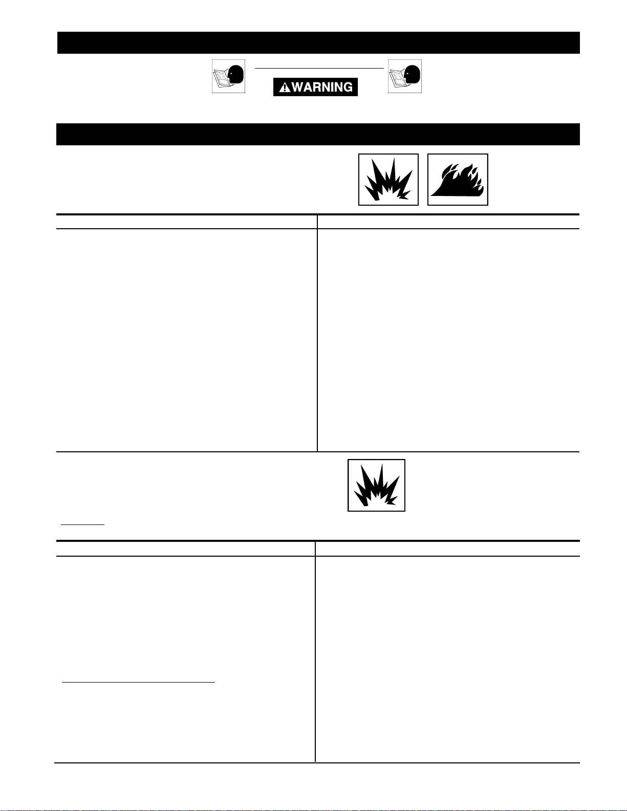
HAZARD
RISK OF EXPLOSION OR FIRE
WHAT CAN HAPPEN
IT IS NORMAL FOR ELECTRICAL CONTACTS WITHIN THE
MOTOR AND PRESSURE SWITCH TO SPARK.
IF ELECTRICAL SPARKS FROM COMPRESSOR COME INTO
CONTACT WITH FLAMMABLE VAPORS, THEY MAY IGNITE,
CAUSING FIRE OR EXPLOSION.
RESTRICTING ANY OF THE COMPRESSOR VENTILATION
OPENINGS WILL CAUSE SERIOUS OVERHEATING AND
COULD CAUSE FIRE.
UNATTENDED OPERATION OF THIS PRODUCT COULD
RESULT IN PERSONAL INJURY OR PROPERTY DAMAGE.
RISK OF BURSTING
HOW TO PREVENT IT
ALWAYS OPERATE THE COMPRESSOR IN A WELL VENTILATED AREA FREE OF COMBUSTIBLE MATERIALS,
GASOLINE OR SOLVENT VAPORS.
IF SPRAYING FLAMMABLE MATERIALS, LOCATE COMPRESSOR AT LEAST 20 FEET AWAY FROM SPRAY AREA. AN
ADDITIONAL LENGTH OF HOSE MAY BE REQUIRED.
STORE FLAMMABLE MATERIALS IN A SECURE LOCATION
AWAY FROM COMPRESSOR.
NEVER PLACE OBJECTS AGAINST OR ON TOP OF COMPRESSOR. OPERATE COMPRESSOR IN AN OPEN AREA AT
LEAST 12 INCHES AWAY FROM ANY WALL OR OBSTRUC-
TION THAT WOULD RESTRICT THE FLOW OF FRESH AIR TO
THE VENTILATION OPENINGS.
OPERATE COMPRESSOR IN A CLEAN, DRY, WELL VENTILATED
AREA. DO NOT OPERATE UNIT INDOORS OR IN ANY CON-
FINED AREA.
ALWAYS REMAIN IN ATTENDANCE WITH THE PRODUCT
WHEN IT IS OPERATING.
AIR TANK: THE FOLLOWING CONDITIONS COULD LEAD TO A WEAKENING OF THE TANK, AND RESULT IN A
VIOLENT TANK EXPLOSION AND COULD CAUSE PROPERTY DAMAGE OR SERIOUS INJURY.
WHAT CAN HAPPEN
1. FAILURE TO PROPERLY DRAIN CONDENSED WATER
FROM THE TANK, CAUSING RUST AND THINNING OF THE
STEEL TANK.
2. MODIFICATIONS OR ATTEMPTED REPAIRS TO THE TANK.
3. UNAUTHORIZED MODIFICATIONS TO THE UNLOADER
VALVE, SAFETY VALVE, OR ANY OTHER COMPONENTS
WHICH CONTROL TANK PRESSURE.
4. EXCESSIVE VIBRATION CAN WEAKEN THE AIR TANK
AND CAUSE RUPTURE OR EXPLOSION.
DRAIN TANK DAILY OR AFTER EACH USE. IF TANK DEVEL-
OPS A LEAK, REPLACE IT IMMEDIATELY WITH A NEW TANK OR
REPLACE THE ENTIRE COMPESSOR.
NEVER DRILL INTO, WELD, OR MAKE ANY MODIFICATIONS
TO THE TANK OR ITS ATTACHMENTS.
THE TANK IS DESIGNED TO WITHSTAND SPECIFIC OPERATING
PRESSURES. NEVER MAKE ADJUSTMENTS OR PARTS
SUBSTITUTIONS TO ALTER THE FACTORY SET OPERATING
PRESSURES.
HOW TO PREVENT IT
ATTACHMENTS & ACCESSORIES:
EXCEEDING THE PRESSURE RATING OF AIR TOOLS, SPRAY
GUNS, AIR OPERATED ACCESSORIES, TIRES AND OTHER
INFLATABLES CAN CAUSE THEM TO EXPLODE OR FLY
APART, AND COULD RESULT IN SERIOUS INJURY.
FOR ESSENTIAL CONTROL OF AIR PRESSURE, YOU MUST
INSTALL A PRESSURE REGULATOR AND PRESSURE GAUGE
TO THE AIR OUTLET OF YOUR COMPRESSOR. FOLLOW THE
EQUIPMENT MANUFACTURERS RECOMMENDATION AND
NEVER EXCEED THE MAXIMUM ALLOWABLE PRESSURE
RATING OF ATTACHMENTS. NEVER USE COMPRESSOR TO
INFLATE SMALL LOW-PRESSURE OBJECTS SUCH AS
CHILDREN’S TOYS, FOOTBALLS, BASKETBALLS. ETC.
3—ENG
MGP-SL10120H-2A
Page 4
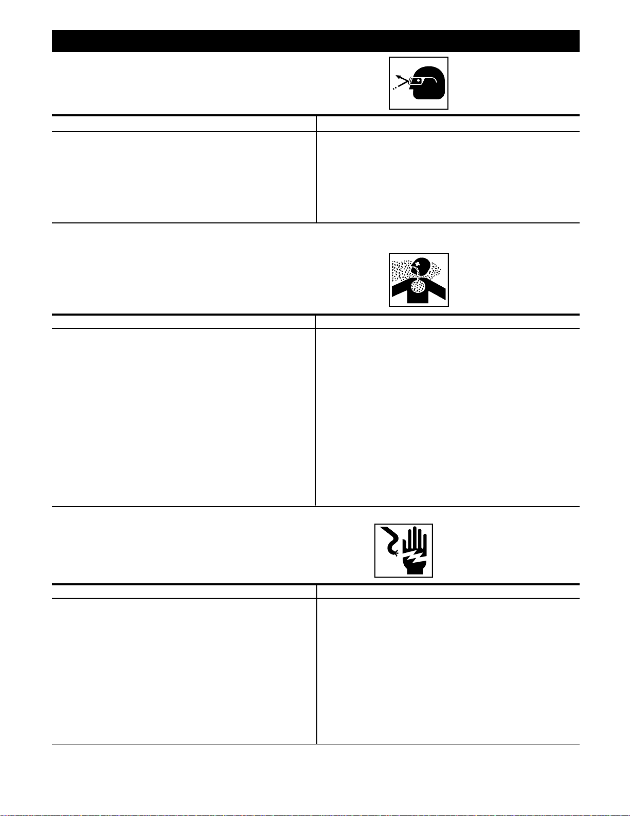
HAZARD
RISK FROM FLYING OBJECTS
WHAT CAN HAPPEN
THE COMPRESSED AIR STREAM CAN CAUSE SOFT TISSUE
DAMAGE TO EXPOSED SKIN AND CAN PROPEL DIRT, CHIPS,
LOOSE PARTICLES AND SMALL OBJECTS AT HIGH SPEED,
RESULTING IN PROPERTY DAMAGE OR PERSONAL INJURY.
RISK TO BREATHING
WHAT CAN HAPPEN
THE COMPRESSED AIR FROM YOUR COMPRESSOR IS NOT
SAFE FOR BREATHING! THE AIR STREAM MAY CONTAIN
CARBON MONOXIDE, TOXIC VAPORS OR SOLID PARTICLES
FROM THE TANK.
HOW TO PREVENT IT
ALWAYS WEAR ANSI Z87.1 APPROVED SAFETY GLASSES
WITH SIDE SHIELDS WHEN USING THE COMPRESSOR.
NEVER POINT ANY NOZZLE OR SPRAYER TOWARD ANY
PART OF THE BODY OR AT OTHER PEOPLE OR ANIMALS.
ALWAYS TURN THE COMPRESSOR OFF AND BLEED PRESSURE FROM THE AIR HOSE AND TANK BEFORE ATTEMPTING
MAINTENANCE, ATTACHING TOOLS OR ACCESSORIES.
HOW TO PREVENT IT
ALWAYS OPERATE AIR COMPRESSOR OUTSIDE IN A CLEAN,
WELL VENTILATED AREA. AVOID ENCLOSED AREAS SUCH AS
GARAGES, BASEMENTS, STORAGE SHEDS, WHICH LACK A
STEADY EXCHANGE OF AIR. KEEP CHILDREN, PETS AND
OTHERS AWAY FROM AREA OF OPERATION.
NEVER INHALE AIR FROM THE COMPRESSOR EITHER
DIRECTLY OR FROM A BREATHING DEVICE CONNECTED TO
THE COMPRESSOR.
SPRAYED MATERIALS SUCH AS PAINT, PAINT SOLVENTS,
PAINT REMOVER, INSECTICIDES, WEED KILLERS, CONTAIN
HARMFUL VAPORS AND POISONS.
RISK OF ELECTRICAL SHOCK
WHAT CAN HAPPEN
YOUR AIR COMPRESSOR IS POWERED BY ELECTRICITY.
LIKE ANY OTHER ELECTRICALLY POWERED DEVICE, IF IT IS
NOT USED PROPERLY IT MAY CAUSE ELECTRIC SHOCK.
REPAIRS ATTEMPTED BY UNQUALIFIED PERSONNEL CAN
RESULT IN SERIOUS INJURY OR DEATH BY ELECTROCUTION.
ELECTRICAL GROUNDING: FAILURE TO PROVIDE ADEQUATE
GROUNDING TO THIS PRODUCT COULD RESULT IN SERIOUS
INJURY OR DEATH FROM ELECTROCUTION. SEE GROUND-
ING INSTRUCTIONS.
WORK IN AN AREA WITH GOOD CROSS-VENTILATION. READ
AND FOLLOW THE SAFETY INSTRUCTIONS PROVIDED ON
THE LABEL OR SAFETY DATA SHEETS FOR THE MATERIAL
YOU ARE SPRAYING. USE A NIOSH/MSHA APPROVED
RESPIRATOR DESIGNED FOR USE WITH YOUR SPECIFIC
APPLICATION.
HOW TO PREVENT IT
NEVER OPERATE THE COMPRESSOR OUTDOORS WHEN IT IS
RAINING OR IN WET CONDITIONS.
NEVER OPERATE COMPRESSOR WITH COVER COMPONENTS
REMOVED OR DAMAGED.
ANY ELECTRICAL WIRING OR REPAIRS REQUIRED ON THIS
PRODUCT SHOULD BE PERFORMED BY AUTHORIZED
SERVICE CENTER PERSONNEL IN ACCORDANCE WITH
NATIONAL AND LOCAL ELECTRICAL CODES.
MAKE CERTAIN THAT THE ELECTRICAL CIRCUIT TO WHICH
THE COMPRESSOR IS CONNECTED PROVIDES PROPER
ELECTRICAL GROUNDING, CORRECT VOLTAGE AND
ADEQUATE FUSE PROTECTION.
MGP-SL10120H-2A
4—ENG
Page 5
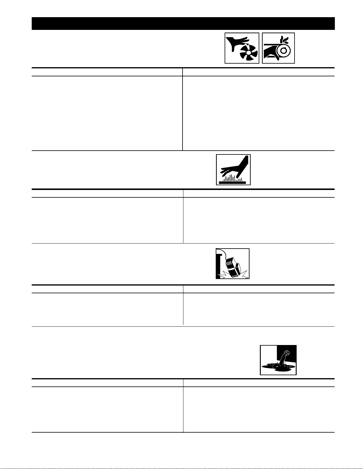
HAZARD
RISK FROM MOVING PARTS
WHAT CAN HAPPEN
MOVING PARTS SUCH AS THE PULLEY, FLYWHEEL AND BELT
CAN CAUSE SERIOUS INJURY IF THEY COME INTO CONTACT
WITH YOU OR YOUR CLOTHING.
ATTEMPTING TO OPERATE COMPRESSOR WITH DAMAGED
OR MISSING PARTS OR ATTEMPTING TO REPAIR COMPRESSOR WITH PROTECTIVE SHROUDS REMOVED CAN
EXPOSE YOU TO MOVING PARTS AND CAN RESULT IN
SERIOUS INJURY.
RISK OF BURNS
WHAT CAN HAPPEN
TOUCHING EXPOSED METAL SUCH AS THE COMPRESSOR
HEAD OR OUTLET TUBES, CAN RESULT IN SERIOUS BURNS.
HOW TO PREVENT IT
NEVER OPERATE THE COMPRESSOR WITH GUARDS OR
COVERS WHICH ARE DAMAGED OR REMOVED.
ANY REPAIRS REQUIRED ON THIS PRODUCT SHOULD BE
PERFORMED BY AUTHORIZED SERVICE CENTER PERSONNEL.
HOW TO PREVENT IT
NEVER TOUCH ANY EXPOSED METAL PARTS ON COMPRESSOR DURING OR IMMEDIATELY AFTER OPERATION. COMPRESSOR WILL REMAIN HOT FOR SEVERAL MINUTES AFTER
OPERATION.
DO NOT REACH AROUND PROTECTIVE SHROUDS OR ATTEMPT
MAINTENANCE UNTIL UNIT HAS BEEN ALLOWED TO COOL.
RISK OF FALLING
WHAT CAN HAPPEN
A PORTABLE COMPRESSOR CAN FALL FROM A TABLE,
WORKBENCH OR ROOF CAUSING DAMAGE TO THE COM-
PRESSOR AND COULD RESULT IN SERIOUS INJURY OR
DEATH TO THE OPERATOR.
RISK OF PROPERTY DAMAGE WHEN TRANSPORTING
COMPRESSOR
(Fire, Inhalation, Damage to Vehicle Surfaces)
WHAT CAN HAPPEN
OIL CAN LEAK OR SPILL AND COULD RESULT IN FIRE OR
BREATHING HAZARD, SERIOUS INJURY OR DEATH CAN RESULT.
OIL LEAKS WILL DAMAGE CARPET, PAINT OR OTHER SURFACES
IN VEHICLES OR TRAILERS.
HOW TO PREVENT IT
ALWAYS OPERATE COMPRESSOR IN A STABLE SECURE
POSITION TO PREVENT ACCIDENTAL MOVEMENT OF THE
UNIT. NEVER OPERATE COMPRESSOR ON A ROOF OR
OTHER ELEVATED POSITION. USE ADDITIONAL AIR HOSE
TO REACH HIGH LOCATIONS.
HOW TO PREVENT IT
ALWAYS PLACE COMPRESSOR ON A PROTECTIVE MAT WHEN
TRANSPORTING TO PROTECT AGAINST DAMAGE TO VEHICLE
FROM LEAKS. REMOVE COMPRESSOR FROM VEHICLE IMMEDIATELY UPON ARRIVAL AT YOUR DESTINATION.
ESW-99 — 9/26/99ESW-99 — 9/26/99
ESW-99 — 9/26/99
ESW-99 — 9/26/99ESW-99 — 9/26/99
5—ENG
MGP-SL10120H-2A
Page 6

SPECIFICATIONS
Refer to cover page for the specifications of your compressor. Use only a fuse or circuit breaker that is the same rating
as the branch circuit the air compressor is operated on. If the compressor is connected to a circuit protected by fuses,
use dual element time delay fuses, as noted in specification chart.
Improper electrical installation of this product
may void its warranty and your fire insurance.
Have circuit wiring performed by qualified personnel such as a licensed electrician who is
familiar with the current national electric code
and any prevailing local electrical codes.
GLOSSARY
CFM:CFM:
CFM: Cubic feet per minute.
CFM:CFM:
SCFM:SCFM:
SCFM: Standard cubic feet per minute; a unit of
SCFM:SCFM:
measure of air delivery.
PSIG: PSIG:
PSIG: Pounds per square inch gauge; a unit of measure
PSIG: PSIG:
of pressure.
ASME:ASME:
ASME: American Society of Mechanical Engineers;
ASME:ASME:
made, tested, inspected and registered to meet the
standards of the ASME.
California CodeCalifornia Code
California Code: Unit may comply with California
California CodeCalifornia Code
Code 462 (l) (2)/(M) (2). Specification/Model Label is on
the side of the tank on units that comply with California
Code.
DUTY CYCLE
Cut-In Pressure:Cut-In Pressure:
Cut-In Pressure: While the motor is off, air tank
Cut-In Pressure:Cut-In Pressure:
pressure drops as you continue to use your accessory.
When the tank pressure drops to a certain low level the
motor will restart automatically. The low pressure at
which the motor automatically re-starts is called “cutin pressure.”
Cut-Out Pressure: Cut-Out Pressure:
Cut-Out Pressure: When you turn on your air com-
Cut-Out Pressure: Cut-Out Pressure:
pressor and it begins to run, air pressure in the air tank
begins to build. It builds to a certain high pressure
before the motor automatically shuts off - protecting
your air tank from pressure higher than its capacity. The
high pressure at which the motor shuts off is called "cutout pressure."
To Lock Out Power:To Lock Out Power:
To Lock Out Power: Place a lock on the line power
To Lock Out Power:To Lock Out Power:
switch so no one else can turn on the power.
All DeVilbiss Air Power manufactured air compressors
should be operated on not more than a 50% duty cycle.
This means an air compressor that pumps more than
50% of one hour, is considered misuse, because the air
MGP-SL10120H-2A
compressor is undersized for the required air demand.
Maximum compressor pumping time per hour is 30
minutes.
6—ENG
Page 7

GENERAL INFORMATION
You have purchased a complete compressor outfit consisting of an air compressor, air tank, electric motor, and
associated controls and instruments. The outfit you have
selected is a stationary model and contains a two stage
air compressor pump.
Your new compressor outfit can be used for operating
paint sprayers, air tools, grease guns, air brushes, caulking guns, sandblasters, inflating tires, etc.
An air pressure regulator is usually necessary for most
applications. An air line filter is normally required for
removal of moisture and oil vapor in compressed air when
a paint spray gun is used.
An in-line lubricator is often required for air tools to prolong
tool life.
ON-RECEIPT INSPECTION
Separate air transformers which combine the functions of
air regulation and/or moisture and dirt removal should
be used where applicable.
A regularly scheduled program of preventive maintenance will help provide the long life that has been
designed into your compressor outfit. Before operating
or performing any maintenance on your compressor, refer
to this manual. To keep your compressor in good working
order, refer to these publications often and perform
preventive maintenance steps as recommended.
Each air compressor outfit is carefully checked before
shipment. With improper handling, damage may result in
transit and cause problems in compressor operation.
Immediately upon arrival, check equipment for both
concealed and visible damages to avoid expenses being
incurred to correct such problems. This should be done
regardless of any visible signs of damage to the shipping
container. Report any damages to carrier and arrange for
inspection of goods immediately.
For the location or a listing of the nearest DeVilbiss Air
Power Authorized Warranty Service Center, call our toll
free number at 1-800-888-2468.
7—ENG
MGP-SL10120H-2A
Page 8

DESCRIPTION OF OPERATION
Drain Valve:Drain Valve:
Drain Valve: At the base of the air tank to drain
Drain Valve:Drain Valve:
condensation at the end of each use.
ON/AUTO-OFF Switch:ON/AUTO-OFF Switch:
ON/AUTO-OFF Switch: Turn this switch ON to
ON/AUTO-OFF Switch:ON/AUTO-OFF Switch:
provide automatic power to the pressure switch and OFF
to remove power.
Air Intake Filter:Air Intake Filter:
Air Intake Filter: This filter is designed to clean air
Air Intake Filter:Air Intake Filter:
coming into the pump. This filter must always be clean
and ventilation openings free from obstructions. See
"Maintenance".
Air Compressor Pump:Air Compressor Pump:
Air Compressor Pump: In two stage compressors, air
Air Compressor Pump:Air Compressor Pump:
is first compressed to an intermediate pressure in the
large bore cylinder, and after passing through an intercooler, the air is further compressed to a higher pressure
in the smaller bore cylinder. This process continues until
the air tank pressure reaches the factory set cutoff
pressure. At that point the pressure switch shuts the
electric motor off.
Check Valve:Check Valve:
Check Valve: When the air compressor is operating,
Check Valve:Check Valve:
the check valve is "open", allowing compressed air to
enter the air tank. When the air compressor reaches
"cut-out" pressure, the check valve "closes", allowing
air pressure to remain inside the air tank.
Pressure Release Valve:Pressure Release Valve:
Pressure Release Valve: The pressure release valve
Pressure Release Valve:Pressure Release Valve:
located on the side of the pressure switch, is designed
to automatically release compressed air from the compressor head and the outlet tube when the air compressor reaches "cut-out" pressure or is shut off. If the air
is not released, the motor will try to start, but will be
unable to. The pressure release valve allows the motor
to restart freely. When the motor stops running, air will
be heard escaping from the valve for a few seconds. No
air should be heard leaking when the motor is running.
Pressure Switch: Pressure Switch:
Pressure Switch: The pressure switch automatically
Pressure Switch: Pressure Switch:
starts the motor when the air tank pressure drops below
the factory set "cut-in" pressure. It stops the motor
when the air tank pressure reaches the factory set "cutout" pressure.
Shut-off Valve:Shut-off Valve:
Shut-off Valve: Turn the knob counterclockwise to
Shut-off Valve:Shut-off Valve:
open the valve and clockwise to close.
Air Tank Safety Valve:Air Tank Safety Valve:
Air Tank Safety Valve: If the pressure switch does not
Air Tank Safety Valve:Air Tank Safety Valve:
shut off the air compressor at its cut-out pressure
setting, the safety valve will protect against high pressure by "popping off" at its factory set pressure (slightly
higher than the pressure switch cut-out setting).
Aftercooler Safety Valve:Aftercooler Safety Valve:
Aftercooler Safety Valve: On two stage compressor
Aftercooler Safety Valve:Aftercooler Safety Valve:
units, safety valve is provided to prevent over-pressurization of the aftercooler. The valve will protect the
aftercooler by "popping off" at its factory set pressure.
Regulator:Regulator:
Regulator: An air pressure regulator or a separate air
Regulator:Regulator:
transformer which combines the functions of air regulation and/or moisture and dirt removal is recommended
for most applications.
Tank Pressure Gauge:Tank Pressure Gauge:
Tank Pressure Gauge: The tank pressure gauge
Tank Pressure Gauge:Tank Pressure Gauge:
indicates the reserve air pressure in the tank. On outfits
with no pressure regulator, this is also the pressure
available at the air outlet.
MGP-SL10120H-2A
8—ENG
Page 9
INSTALLATION AND BREAK-IN PROCEDURES
Location of the Air Compressor
THE PUMP ASSEMBLY DOES NOT PROVIDE ADEQUATE STABILITY OR SUPPORT
FOR LIFTING THE UNIT. IF THE OUTFIT
MUST BE MOVED, USE THE TANK FOR
LIFTING.
This compressor should be permanently mounted in
place on a level floor. Operate the air compressor in a
clean, dry and well ventilated area. The air intake filter
must be kept clear of obstructions which could reduce air
delivery of the air compressor. The air compressor
should be located at least 12" away from walls or other
obstructions that could interfere with the flow of air
through the fan bladed flywheel. The air compressor
crankcase and head are designed with fins to provide
proper cooling.
The flywheel side of the outfit should be placed toward
the wall and protected with a totally enclosed belt guard.
In no case should the flywheel be closer than 12 to 18
inches from the wall or other obstruction that will interfere
with the flow of air through the fan bladed flywheel. The
area should allow space on all sides for air circulation
and for ease of normal maintenance. Keep the outfit
away from areas which have dirt, vapor and volatile fumes
in the atmosphere which may clog and gum the intake
filter and valves, causing inefficient operation. Where this
is not practical a remote air intake is recommended.
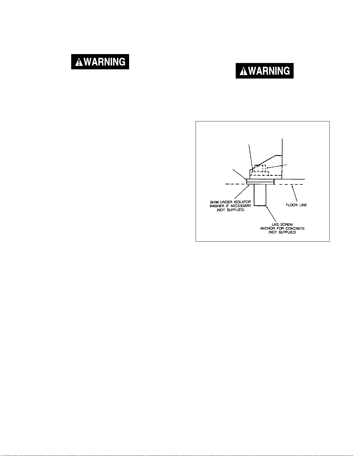
Air Compressor Anchoring
Methods
VIBRATION CAN WEAKEN THE AIR TANK
AND CAUSE AN EXPLOSION. THE COMPRESSOR MUST BE PROPERLY MOUNTED
AS ILLUSTRATED BELOW.
FLAT WASHER
ISOLATOR
WASHER
(supplied)
Anchoring of Horizontal Unit
LAG SCREW
(NOT SUPPLIED)
TORQUE TO
5 TO 10 FT-LB
Note
Where a remote air intake is used, enlarge the size of the air intake piping by
one pipe size for each 10 feet of length.
If humidity is high, an air filter can be installed to
remove excessive moisture. Closely follow instructions packaged with the filter for proper installation. It
must be installed as close as possible to the accessory.
The air compressor should be as near to air outlets as
possible in order to avoid long pipe lines. Do not place
the air compressor where heat is excessive.
9—ENG
Horizontal Units
Horizontal air compressors must be bolted to the floor.
Bolting holes are provided in the base feet. Mount the
air compressor on a solid, level foundation. Support
compressor weight evenly on all four feet. Solid shims
may be used if necessary.
MGP-SL10120H-2A
Page 10
INSTALLATION AND BREAK-IN PROCEDURES
Wiring Instructions
If your compressor unit is not equipped with a plug-in type
power cord, perform electrical wiring according to the
following instructions:
IMPROPER ELECTRICAL GROUNDING CAN
RESULT IN A RISK OF ELECTRICAL SHOCK.
WIRING SHOULD BE DONE BY A LICENSED
ELECTRICIAN IN ACCORDANCE WITH NATIONAL AND LOCAL CODES AND ORDINANCES.
Install the compressor outfit as close to the main power
supply as possible. This practice will avoid using long
lengths of electrical wiring for the power supply which can
cause power loss to the motor. When connecting wires
make sure that:
1.The amperage rating of the electrical box is adequate.
Refer to the Specification Chart (cover page) for your
air compressor outfit.
2.The supply line has the same electrical characteristics
(voltage, cycle, and phase) as motor.
Wiring must be such that full motor nameplate voltage
plus or minus 10%, is available at the motor terminals
during starting. Refer to local codes for recommended
wire sizes for correct wire size and maximum wire run;
undersize wire causes high amp draw and overheating to
the motor.
Electrical wiring must be located away
from hot surfaces such as the compressor
head, compressor cylinder, or compressor outlet tube.
Voltage and Circuit Protection
Refer to The Specification Chart for the voltage and circuit
protection requirements of your compressor. Use only a
fuse or circuit breaker that is the same rating as the branch
circuit the air compressor is operated on. If the compressor
is connected to a circuit protected by fuses, use only dual
element time delay fuses. See Specification Chart.
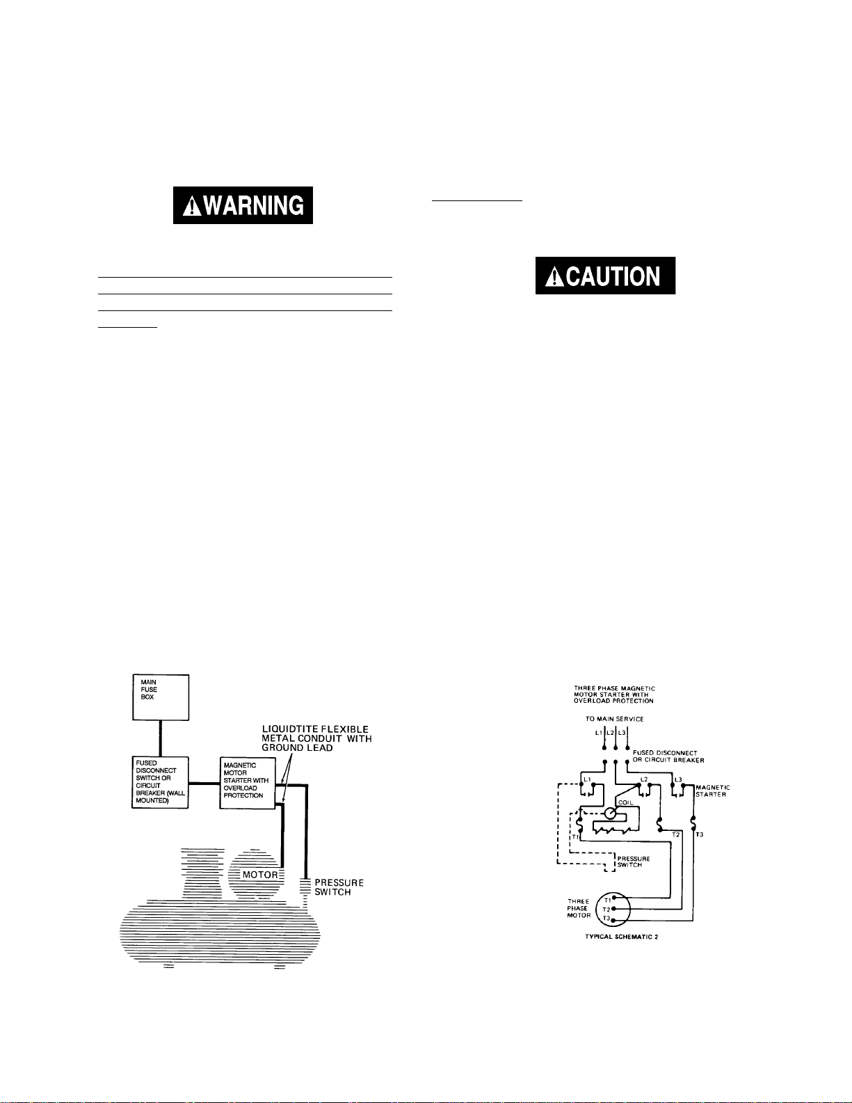
Wiring of Compressor Units
Typical Wiring of Compressor Units
With more than 80 Gallons Capacity
IF REQUIREDIF REQUIRED
IF REQUIRED
IF REQUIREDIF REQUIRED
Typical schematic subject to all changes as dictated by
local electrical codes and authorities.
NOTE: THESE OUTFITS DO NOT INCLUDE ANY
MGP-SL10120H-2A
WIRING BECAUSE OF VARIOUS
INSTALLATION REQUIREMENTS.
10—ENG
Page 11
INSTALLATION AND BREAK-IN PROCEDURES
Air Filter Installation
To install air filter:
Insert threaded end of the air filter assembly into elbow
and tighten until snug.
Break-In Procedures
Serious damage may result if the following break-in instructions are not
closely followed.
The Break-In Procedure is required when:
A. New compressor is put into service.
B. Check valve is replaced
C. New pump is installed on tank.
1.Recheck compressor wiring. Make sure wires are
secure at all terminal connections. Free all contacts of
loose wire cuttings, etc.
Do not operate compressor without air
filter assembly installed as this will
cause damage to the compressor.
Additional Regulators and
Controls
Since the air tank pressure is usually greater than that
which is needed, a separate regulator is usually employed
to control the air pressure ahead of any individual air driven
device.
Separate air transformers that combine the functions of air
regulation and moisture and dirt removal should be used
where applicable.
Lubrication and Oil
2.Open the air outlet valve fully to permit air to escape
and prevent air pressure build-up in the tank during the
break-in period.
3.Position the fuse disconnect or circuit breaker to the
ON position and, if equipped, turn the ON/AUTO-OFF
switch on the pressure switch to the ON position.
4. Run the compressor for 30 minutes. Make sure the air
outlet, or globe valve, is open and there is no tank
pressure build-up.
5.Check for excessive vibration and noise. Adjust air
compressor belt guard as necessary to eliminate
chatter. Re-adjust or shim the air compressor feet, if
necessary, for proper level.
6. Close the outlet valve and let air compressor pump up
to "cut-out pressure". Turn the air compressor off and
check oil level. Add oil if necessary. Connect air hose
to air outlet adapter.
7. Check all air line fittings and connections/piping for air
leaks by applying a soap solution. Correct as necessary. Even minor leaks can cause this air compressor
to overwork, resulting in premature breakdown or
inadequate performance.
Multi-viscosity motor oils like 10W30, should
not be used in an air compressor. They
leave carbon deposits on critical components, thus reducing performance and compressor life. Use air compressor oil only.
See Maintenance for oil recommendations.
Compressors are shipped without oil. A
small amount of oil may be present in the
pump upon receipt of the air compressor.
This is due to plant testing and does not
mean that the pump contains oil. Do not
attempt to operate in order to check wiring
or for any reason without first adding oil to
the crankcase. Serious damage to the pump
can result from even very limited use without oil. Fill crankcase with recommended
oil before operating.
Remove the oil fill plug and fill the crankcase with recommended oil. Refer to the Service Instructions in this manual
for the specific oil recommended for use in your compressor unit. Replace the oil fill plug. Always fill to middle of
sight glass.
11—ENG
MGP-SL10120H-2A
Page 12
INSTALLATION AND BREAK-IN PROCEDURES
Piping
Plastic or PVC pipe is not designed for use
with compressed air. Regardless of its indicated pressure rating, plastic pipe can burst
from air pressure. Use only metal pipe for
air distribution lines.
NoteNote
Note
NoteNote
Where a remote air intake is used, enlarge the size of the air intake piping by
one pipe size for each 10 feet of length.
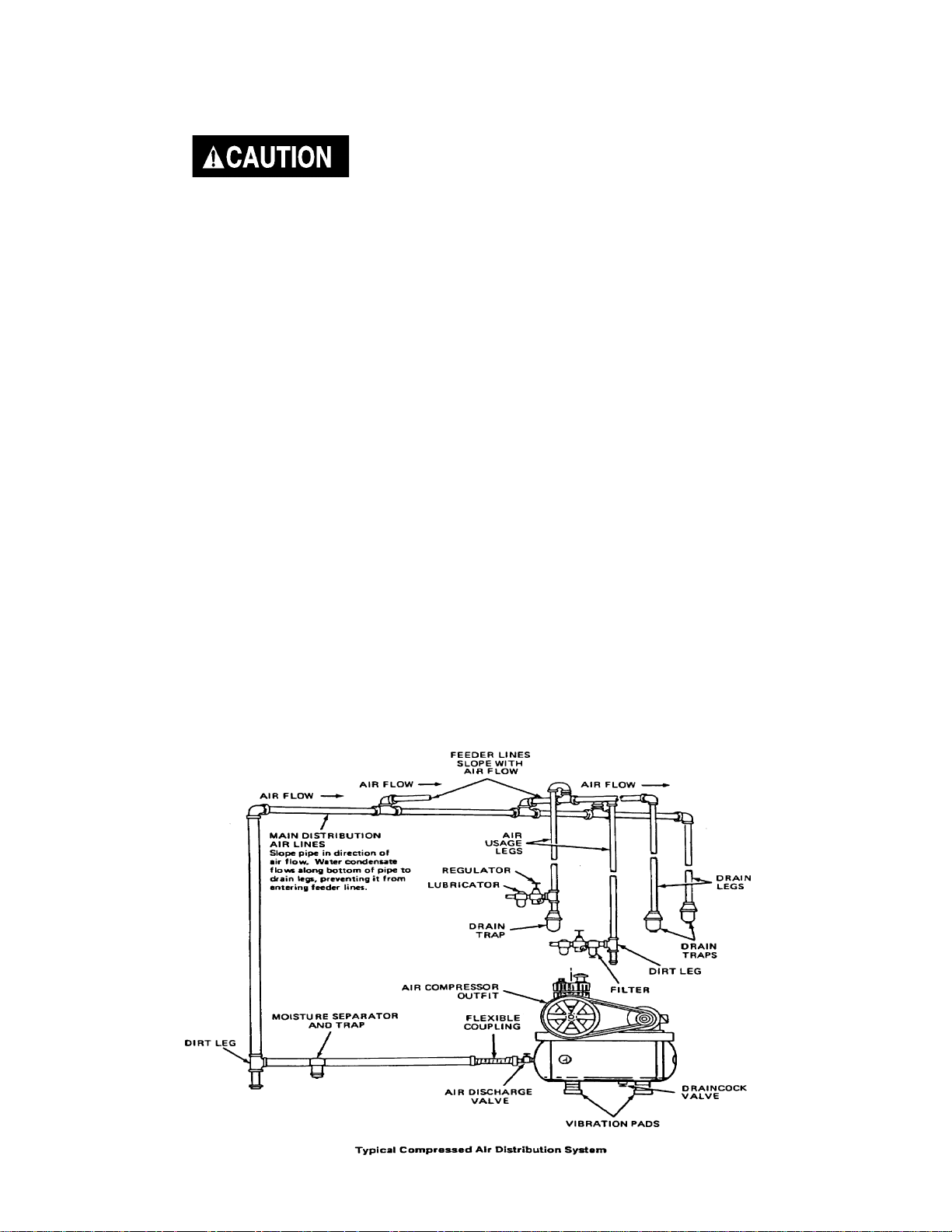
A typical compressed air distribution system as shown
below should be of sufficient pipe size to keep the
pressure drop between the supply and point of use to a
minimum. All pipes and fittings used must be certified
safe for the pressures involved. Pipe thread sealant must
be used on all threads, and all joints are to be made up
tight, since small leaks in the piping system are the
largest single cause of high operating costs.
All piping should be sloped to an accessible drain point
and all outlets should be taken from the top of the main
distribution air line so that moisture cannot enter the
outlet.
The main distribution air line should not be smaller than
the compressor air discharge valve outlet. A smaller line
will restrict the flow of air. If piping is over 100 feet long,
or if required air flow will exceed 15 SCFM, use 3/4"
piping.
NoteNote
Note
NoteNote
For underground installation, bury air
lines below the frost line and avoid
pockets where condensation can gather
and freeze. Apply pressure before underground lines are covered to make
sure all pipe joints are free from leaks.
It is recommended that a flexible coupling be installed
between the air discharge valve outlet and main air
distribution line to allow for vibration.
To remove dirt, oil and water, install a separator in the
main distribution line. Install separator a minimum of 5 to
6 feet from compressor to allow the air to cool to room
temperature before passing through the separator. Additional separators or filters may be used depending on the
application.
Liquid water occurs naturally in air lines as a result of
compression. Moisture vapor in ambient air is concentrated when pressurized and condenses when cooled in
downstream air piping. Compressed air dryers reduce
the water vapor concentration and prevent liquid water
formation in compressed air lines. Dryers are a necessary companion to filters, aftercoolers, and automatic
drains for improving the productivity of compressed air
systems.
Water and water vapor removal increases the efficiency
of air operated equipment, reduces contamination and
rusting, increases the service life of pneumatic equipment and tools, prevents air line freeze-ups, and reduces
product rejects. The use of dryers and filters are recommended when these moisture related problems are
reported to our factory or distributor service department.
MGP-SL10120H-2A
12—ENG
Page 13
OPERATING PROCEDURES
1. Before attaching an air hose or accessory, make sure the
outlet valve is in the closed position. On units equipped
with a pressure switch lever make sure the switch is in the
OFF position.
Compressed air from the outfit may contain
water condensation and oil mist. Do not spray
unfiltered air at an item that could be damaged by moisture or oil mist. Some air operated tools or devices may require filtered air.
Read instructions for air tool or device.
2.Attach regulator, hose and accessory. On models
without an air pressure regulator, one must be installed
before using accessories.
TOO MUCH AIR PRESSURE CAUSES A HAZARDOUS RISK OF BURSTING. CHECK THE
MANUFACTURER'S MAXIMUM PRESSURE
RATING FOR AIR TOOLS AND ACCESSORIES.
THE REGULATOR OUTLET PRESSURE MUST
NEVER EXCEED THE MAXIMUM PRESSURE
RATING.
3. Turn the compressor on and allow tank pressure to build.
On units equipped with a pressure switch lever, place the
switch in the ON-AUTO position. The motor will stop
when tank pressure reaches "cut-out pressure".
When You Are Finished:
6. Turn the compressor unit off.
7. Turn the regulator counterclockwise and set the outlet
pressure to zero.
8. Remove the air tool or accessory.
9. Open the regulator and allow the air to slowly bleed
from the tank. Close the regulator when tank pressure
is approximately 20 psi.
10. Open the drain cock valve underneath the tank and
drain water from air tank. Collect the water in a suitable
containter. Continue operating unit until all moisture is
removed from the air tank.
DRAIN TANK DAILY. WATER WILL CONDENSE
IN THE AIR TANK. IF NOT DRAINED, THE WATER WILL CORRODE AND WEAKEN THE AIR
TANK, CAUSING A RISK OF AIR TANK RUPTURE. THE AIR TANK MUST BE DRAINED PROPERLY.
11. After the water has been drained, close the drain cock.
- if the compressor is under continuous use - drain at
least once each day.
4. Open the outlet valve.
5. If an air pressure regulator is in use, open the regulator by
turning it clockwise. Adjust the regulator to the correct
pressure setting. Your outfit is ready for use.
- if the compressor is only used occasionally - drain
after each use.
Note
If drain cock valve is clogged, release air pressure in air tank. The drain cock valve can then
be removed, cleaned and reinstalled.
13—ENG
MGP-SL10120H-2A
Page 14
MAINTENANCE
UNIT CYCLES AUTOMATICALLY WHEN POWER IS ON. DURING MAINTENANCE, YOU COULD BE
EXPOSED TO VOLTAGE SOURCES, COMPRESSED AIR OR MOVING PARTS. PERSONAL INJURIES
CAN OCCUR. DISCONNECT POWER SOURCE AND BLEED OFF ALL AIR TANK PRESSURE BEFORE
DOING ANY MAINTENANCE OR REPAIR. NEVER OPERATE THE UNIT WITH THE BELT GUARD
REMOVED.
To ensure efficient operation and longer life of the air compressor outfit, a routine maintenance schedule should be
prepared and followed. The following routine maintenance schedule is geared to an outfit in a normal working environment
operating on a daily basis. If necessary, the schedule should be modified to suit the conditions under which your
compressor is used. The modifications will depend upon the hours of operation and the working environment. Compressor
outfits in an extremely dirty and/or hostile environment will require a greater frequency of all maintenance checks.
A clean air compressor runs cooler and provides longer service. Clean or blow off fins and any other parts of the air
compressor that collect dust or dirt. Do not place rags, containers or other material on or against the ventilation openings
in the belt guard. Adequate ventilation is necessary to maintain proper air compressor operating temperature.
Routine Maintenance Schedule
Every 8 Hours of Operation
1. Check oil level. Add if necessary.
2. Drain water from the air tank, any moisture
separators or transformers.
Overfilling with oil will cause premature
compressor failure. Do not overfill.
3. Check for any unusual noise and/or vibration.
4. Manually check all safety valves to make sure they
are operating properly.
5. Inspect for oil leaks and repair any leaks found.
6. Clean and inspect the air intake filter; replace if
necessary.
Every 40 Hours of Operation
1. Inspect condition of drive belt; replace if
necessary.
First 100 Hours of Operation
1. Drain and refill compressor crankcase with clean
oil. Refer to Service Instructions for recommended
oils.
2. Increase frequency of oil changes if humidity or
operating conditions are extreme.
Every 160 Hours of Operation
1. Check drive belt tension; adjust if necessary. (Refer
to Service Instructions in this manual.)
2. Inspect air lines and fittings for leaks; correct as
necessary.
3. Check the alignment of the motor pulley to the fly
wheel. If necessary, align to within 1/32 inch on
centerline.
Every 300 Hours of Operation
1. Drain and refill compressor crankcase with clean
oil. Refer to Service Instructions for recommended
oils.
2. Increase frequency of oil changes if humidity or
operating conditions are extreme.
Each Year of Operation (2000 Hours or if a
Problem is Suspected)
Check condition of air compressor pump intake and
exhaust valves. Replace if damaged or worn out.
MGP-SL10120H-2A
14—ENG
Page 15
SERVICE INSTRUCTIONS
Air Filter - Inspection and
Replacement
NOTENOTE
NOTE
NOTENOTE
Keep the air filter clean at all times. Do
not operate the compressor with the air
filter removed.
A dirty air filter will not allow the compressor to operate
at full capacity. Before you use the compressor, check
the air filter to be sure it is clean. If it is dirty, replace it
with a new filter.
Oil - Checking and Changing
Overfilling with oil will cause premature
compressor failure. Do not overfill.
1. Check oil level in compressor crankcase before
each use. The oil level should be to the middle of
the oil sight glass.
2. Replace the oil after initial 100 hours of operation
- thereafter, every 300 hours of operation.
3. Remove the oil fill and drain plugs. Collect the oil
in a suitable container.
4. Replace the oil drain plug and refill the crankcase
with recommended oil. Always fill to middle of sight
glass.
Oil Chart
Room or Ambient
Temperature
Cold Climates - 10º F
Moderate Climates 30º to 80º F
Hot Climates - 80º F
A compressor grade non-detergent oil should be used.
Most automotive detergent oils cause excessive carbon
buildup and should not be used. Please note that all units
run at a constant speed (not start and stop) and should
be lubricated by Rarus 847, Shell turbo 100, or Anderol
synthetic compressor oil. Do not use synthetic oil for the
first 300 hours. All units should be broken in on petroleum based oil.
Oil
Weight
20 Wt.
30 Wt.
40 Wt.
Type
Reciprocating
Non-detergent
petroleum based
compressor rated or
better oil
Check Valve - Inspection and
Replacement
Remove and inspect the check valve at least once a
year or more often if the compressor is heavily used.
Moisture and other contaminants in the hot compressed
air will cause an accumulation of a carbon-like residue
on the working parts. If the valve has heavy carbon
build-up, it should be replaced. Use the following procedure to inspect, clean or replace the check valve.
NoteNote
Note
NoteNote
It is important to maintain the proper oil
level. A low oil level reduces proper cylinder wall lubrication and increases ring
wear.
5. Replace the oil fill plug.
6. Start the compressor outfit and run for several
minutes. Shut the compressor down and check the
oil level. If necessary, add more oil.
1. Turn compressor off and disconnect or lock out
power source.
2. Release air pressure from the air tank.
3. Loosen the top and bottom tube nuts and remove the
outlet tube.
4. Loosen pressure release tube nuts, disconnect from
check valve and move tube aside.
5. Unscrew the check valve with a wrench.
15—ENG
MGP-SL10120H-2A
Page 16

SERVICE INSTRUCTIONS
6. Check that the valve disc moves freely and that the
spring holds the disc in the upper, closed position.
The check valve may be cleaned with a solvent.
7. Apply sealant to the check valve threads. Reinstall
the check valve. Do not overtighten.
8. Replace the outlet tube and tighten top and bottom
nuts. Do not overtighten.
9. Replace the pressure release tube and tighten nuts.
Do not overtighten.
Safety Valve - Inspection and
Replacement
SERIOUS INJURY OR DAMAGE MAY OCCUR
IF PARTS OF THE BODY OR LOOSE ITEMS
GET CAUGHT IN MOVING PARTS. NEVER
OPERATE THE OUTFIT WITH THE BELT
GUARD REMOVED. THE BELT GUARD
SHOULD BE REMOVED ONLY WHEN THE
COMPRESSOR POWER IS DISCONNECTED.
Adjusting Belt Tension
Adjust belt tension as described below.
For compressors with a motor slide mount, adjust belt
tension as follows:
1. Slide motor away from compressor until desired
tension is obtained.
IF THE SAFETY VALVE DOES NOT WORK
PROPERLY, OVER-PRESSURIZATION MAY
OCCUR, CAUSING AIR TANK RUPTURE OR
EXPLOSION. OCCASIONALLY PULL THE
RING ON THE SAFETY VALVE TO MAKE
SURE THAT THE SAFETY VALVE OPERATES FREELY. IF THE VALVE IS STUCK OR
DOES NOT OPERATE SMOOTHLY, IT MUST
BE REPLACED WITH A VALVE HAVING THE
SAME PRESSURE RATING.
The safety valve is set at the factory to a pressure
approximately 15 pounds higher than the rated pressure
of the outfit. If the pressure switch malfunctions and does
not shut off the motor automatically at maximum tank
pressure, the safety valve will protect the air tank against
excessive air pressure by popping off at its preset
pressure.
On two stage compressors, the belt should deflect
1/2" at midway between the pulley and the flywheel.
MGP-SL10120H-2A
2. Tighten two outside cap screws enough to hold the
motor in place for checking pulley and flywheel
alignment.
3. Tighten all four mounting screws to 20-25 ft.-lbs.
16—ENG
Page 17
SERVICE INSTRUCTIONS
Motor Pulley and Flywheel
Alignment
1. Remove outer beltguard - To remove, loosen and
remove beltguard screws located at top of beltguard.
Insert a flat bladed screwdriver and pry beltguard
apart.
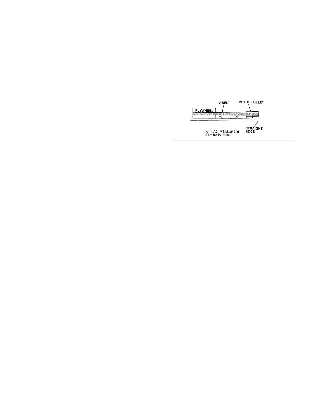
2. Place a straight edge along the outside face of the
compressor flywheel to check alignment of V-belt
grooves. (See figure below for proper alignment.)
3. If the belt grooves aren't aligned, continue with step
4 of this procedure. If the belt grooves are aligned,
continue with step 6 of this procedure.
4. Loosen pulley set screw and adjust pulley until it is in
proper alignment.
5. Tighten pulley set screw to 145-165 in.-lbs.
6. Reinstall belt guard.
Additional Service
Disassembly or service of the air compressor beyond
what is covered in this manual is not recommended.
If additional service is required, contact your nearest
Authorized Warranty Service Center.
STORAGE OF COMPRESSOR OUTFIT
1. Review the Maintenance section on the preceding
pages and perform scheduled maintenance as
necessary. Drain the water from the air tank.
2. Turn compressor off and disconnect or lock out
power source.
3. Remove any air tool or accessory.
4. Protect the electrical cord and/or air hose from
damage (such as being stepped on or run over).
5. Store the compressor in a clean and dry location.
17—ENG
MGP-SL10120H-2A
Page 18

TROUBLESHOOTING GUIDE
PERFORMING REPAIRS MAY EXPOSE VOLTAGE SOURCES, MOVING PARTS OR COMPRESSED AIR
SOURCES. PERSONAL INJURY MAY OCCUR. PRIOR TO ATTEMPTING ANY REPAIRS, DISCONNECT
POWER SOURCE FROM THE COMPRESSOR AND BLEED OFF ALL TANK AIR PRESSURE.
PROBLEM
Excessive tank pressure - safety
valve pops off (units with ONAUTO switch).
Excessive tank pressure - safety
valve pops off (units without
ON-AUTO switch).
Air leaks at fittings or hose.
Air leaks at or inside check valve. Def ective or dir ty check valve.
CAUSE CORRECTION
Pressure switch does not shut off motor when compressor reaches “cut-out"
pressure.
Pressure switch "cut-out" too high.
Incorrect wiring connections.
Pressure switch does not shut off motor when compressor reaches "cut-out
pressure".
Incorrect wiring connections.
Tube fittings are not tight enough.
Move the pressure switch lever to the "OFF" position.
If the outfit doesn’t shut off, and the electrical contacts
are welded together, replace the pressure switch.
Contact Service Center to check and adjust, or replace
switch.
See "Wiring of Compressor Units".
Pressure switch must be replaced.
See "Wiring of Compressor Units".
Tighten fittings where air can be heard escaping.
Check fittings with soapy water solution. DO NOT
OVER-TIGHTEN.
A defective check valve results in a constant air leak at
the pressure release valve when there is pressure in the
tank and the compressor is shut off. Remove and clean
or replace check valve. DO NOT OVER-TIGHTEN.
Air leaks at pressure switch release valve during running.
Continuous air relieving from
pressure switch release valve
after shut off.
Air leaks in air tank or at air tank
welds.
Air leak from safety valves. Possible defect in safety valves.
Squealing sound.
Defective pressure switch release valve. Remove and replace the release valve.
Defective check valve. See "Air Leak at Check Valve."
Defective air tank.
Loose belt.
There is no oil in the compressor.
Air tank must be replaced.
DO NOT DRILL INTO, WELD, OR OTHERWISE
MODIFY AIR TANK. IT WILL WEAKEN. THE
TANK CAN RUPTURE OR EXPLODE.
Operate safety valves manually by pulling on ring. If a
valve still leaks, it should be replaced.
Adjust belt tension. (See Belt Replacement.)
Add oil. (See Oil-Checking and Changing)
MGP-SL10120H-2A
18—ENG
Page 19

TROUBLESHOOTING GUIDE
Motor will not run.
CAUSEPROBLEM
Motor overload protection switch has
tripped.
Tank pressure exceeds pressure switch
"cut-in pressure".
Check valve stuck open.
Loose electrical connections.
Possible defective capacitor.
Paint spray on internal motor parts.
Possible defective motor.
Fuse blown, circuit breaker tripped.
CORRECTION
Let motor cool off for 10-15 minutes and overload
protection switch will reset automatically. If the overload still trips, check for defective capacitor.
Motor will start automatically when tank pressure
drops below "cut-in pressure" of pressure switch.
Remove and clean or replace. DO NOT OVERTIGHTEN.
Check wiring connection inside pressure switch and
motor terminal box area.
Contact Service Center for inspection or replacement
if necessary.
Have checked by Service Center. Do not operate the
compressor in the spray area. See Flammable Vapor
Warning.
Have checked by a local Service Center.
1. Check fuse box for blown fuse and replace if
necessary. Reset circuit breaker. Do not use a fuse
or circuit breaker with higher rating than that
specified for your particular branch circuit.
2. Check for proper fuse; only dual element time
delay fuses are acceptable. Use
fuses. Time delay fuses should be marked
"D" in Canada and "T" in the US.
only time delay
Excessive belt wear.
enough air to operate accessories.
Pressure release valve on pressure
switch has not unloaded head pressure.
Loose belt/tight belt.
Loose pulley.
Prolonged excessive use of air. Decrease amount of air usage.Compressor is not supplying
Compressor is not large enough for air
requirement.
Restricted air intake filter.
3. Check for low voltage conditions.
4. Remove check valve and clean or replace if it is
stuck open or closed.
5. Disconnect the other electrical appliances from
circuit or operate the compressor on its own
branch circuit.
On an on/auto pressure switch equipped with a pressure relief valve, bleed the line by pushing the pressure
switch to the OFF position. If valve does not open,
bend the lever until it does. If valve still fails to bleed,
replace the valve assembly.
Adjust belt tension. (See Belt Replacement.)
Check for worn keyway or pulley bore. Also check for
bent motor shaft. Replace parts if necessary.
Check the accessory air requirement. If it is higher than
the CFM or pressure supplied by your air compressor,
you need a larger compressor.
Clean or replace air intake filter. Do not operate the
compressor in the paint spray area.
19—ENG
MGP-SL10120H-2A
Page 20

TROUBLESHOOTING GUIDE
CAUSEPROBLEM
Compressor is not supplying
enough air to operate accessories. (Continued)
Knocking noise.
Excessive oil consumption. Replace the air intake.
Loose belt.
Hole in hose.
Check valve restricted.
Air leaks.
Defective check valve.
Low oil level.
Loose flywheel.
Loose compressor mounting screws.
Belt too tight/too loose.
Carbon build-up.
Restricted air intake.
CORRECTION
Adjust belt tension.
Check and replace if required.
Remove and clean or replace.
Tighten fittings. (See "Air Leaks" section of "Troubleshooting Guide".)
Remove and clean or replace.
Tighten pulley set screw, 145 to 165 in.-lbs.Loose pulley.
Maintain prescribed oil level. Add oil.
Tighten screw, 33 to 37 ft.-lbs.
Check screws. Tighten as required.
Adjust belt tension. (See Belt Replacement.)
Remove the head. Clean the valves and the top of the
piston. (Be sure carbon does not fall into the cylinder.)
Reassemble using new gaskets and torque screws,
117-207 ft.-lbs.
Compressor overheating.
Motor overheating.
Compressor overworked.
Poor quality oil.
The compressor is overworked. Reduce air consumption or add another air compres-
The check valve is restricted.
Dirty compressor. Clean the compressor thoroughly.
High ambient temperature.
Incorrect oil, low oil. See oil recommendation under Maintenance.
Low voltage.
Pressure switch set beyond factory setting.
Belt too tight.
Compressor valves have excessive carbon deposits build-up; restricted check
valve.
Reduce air consumption or add another air compressor to take up some of the load.
Drain pump and replace with correct oil. Refer to
Lubrication and Oil Section.
sor to take up some of the load.
Inspect the check valve. Clean if necessary.
Use remote air intake.
Dirty or defective check valve.Compressor starting against load.
Provide correct voltage. Consult local power company or electrician.
Do not set switch beyond maximum for which outfit
was designed as noted on nameplate.
Adjust for proper tension.
Clean or replace compressor valves or check valve.
MGP-SL10120H-2A
20—ENG
Page 21

TROUBLESHOOTING GUIDE
PROBLEM
Motor overheating.
(Continued)
Water in pump crankcase; oil
appears milky in color.
CAUSE CORRECTION
Too many motor starts per hour. Consult Service Center.
Improper wiring gauge.
Incorrect voltage.
Current style electric motors run relatively hot under normal operating
conditions, with reasonable compressor loading. This condition is normal
and no adjustment is necessary.
Under normal operating conditions, the motor amperage draw will not
exceed the nameplate amperage rating, plus the service factor, as it appears
on the electric motor. If a condition of sustained high amperage exists, refer
to service checks above and/or consult electrician. If cause cannot be isolated
by an electrician, consult with Service Center for additional assistance.
Humid operating conditions.
Unit not reaching proper operating
temperature because the compressor runs infrequently and is oversized
for the air requirement.
Check electrical hookup and installation data or consult electrician.
NOTENOTE
NOTE
NOTENOTE
Relocate compressor outfit, or change oil frequently.
Consult Service Center.
Liquid water or moisture in air
lines.
Condensation forms in air lines when
the warm compressed air coming
from the air tank starts to cool down
as it travels through the air lines.
Install compressed air dryer sized for the flow and
dryness level required.
21—ENG
MGP-SL10120H-2A
Page 22

COMPRESSOR DIAGRAM
MGP-SL10120H-2A
22—ENG
Page 23

COMPRESSOR PARTS LIST
Key Part
No. Number Description
1 Z-BAL-T59S PUMP ASSEMBLY
2 Z-MO-9082 MOTOR
3 Z-D20596 PRESSURE SWITCH ASSEMBLY
4 TIA-4200 SAFETY VALVE
5 Z-GA-360 PRESSURE GAUGE
6 SSV-6-B BALL VALVE
7 AC-0485 BELTGUARD BRACKET (2)
8 PU-2906 MOTOR PULLEY
9 BT-316 BELT (2)
10 AC-0478 CONTACTOR BOX
11 AC-0465 CHECK VALVE
12 AC-0582 3/4" OUTLET TUBE
13 SSP-7815 3/4" NUT/SLEEVE ASSEMBLY (2)
14 AC-0459 1/4" PRESSURE RELIEF TUBE
15 SSP-7811 1/4" NUT/SLEEVE ASSEMBLY
16 CAC-95 MANIFOLD
Part Not Shown
SSF-8131 BELTGUARD NUT (2)
D23000 DRAIN VALVE
AC-0460-1 INSIDE BELTGUARD
AC-0461 OUTSIDE BELTGUARD
SSF-953-ZN BELT GUARD SCREW (2)
23—ENG
MGP-SL10120H-2A
Page 24

COMPRESSOR PUMP DIAGRAM
MGP-SL10120H-2A
24—ENG
Page 25

PARTS LIST
Key Part
No. Number Description
1 BAL-7061400 HEAD
2 BAL-7040050 VALVE PLATE ASSEMBLY
3 BAL-9049011 SAFETY VALVE, AFTERCOOLER
4 AC-0415 FILTER ASSEMBLY
5 AC-0583 FLYWHEEL
6 BAL-1000112 OIL BREATHER ASSEMBLY
7 BAL-9022003 OIL SIGHT GLASS
8 BAL-1000506 OIL PLUG 1/2"
9 BAL-9110022 FLYWHEEL BOLT
10 BAL-9004009 FLYWHEEL WASHER
11 BAL-9049020 SAVETY VALVE, INNERCOOLER
12 K-0589 GASKET KIT
13 K-0590 RING KIT
NOTICE: When ordering repair parts for your Pump Assembly use this page.
25—ENG
MGP-SL10120H-2A
Page 26

SERVICE NOTES
MGP-SL10120H-2A
26—ENG
Page 27

LIMITED WARRANTY
DeVilbiss Air Power Company warrants to the original purchaser who uses the product in a consumer application (personal,
residential or household usage) that all products covered under this warranty are free from defects in material and
workmanship for one year from the date of purchase. All products covered by this limited warranty which are used in
commercial applications (i.e., income producing) are warranted to be free of defects in material and workmanship for 90
days from the date of original purchase. Products covered under this warranty include air compressors, air tools, service
parts, pressure washers, and generators.
DeVilbiss Air Power Company will repair or replace, at DeVilbiss' option, products or components which have failed within
the warranty period. Service will be scheduled according to the normal work flow and business hours at the service center
location, and the availability of replacement parts. All decisions of DeVilbiss Air Power Company with regard to this limited
warranty shall be final.
This warranty gives you specific legal rights, and you may also have other rights which vary from state to state.
RESPONSIBILITY OF ORIGINAL PURCHASER (initial User):
• To process a warranty claim on this product, DO NOT return it to the retailer. The product must be evaluated by
an Authorized Warranty Service Center. For the location of the nearest Authorized Warranty Service Center call
1-800-888-2468, 24 hours a day, 7 days a week or visit our web site @ devap.com.
• Retain original cash register sales receipt as proof of purchase for warranty work.
• Use reasonable care in the operation and maintenance of the product as described in the Owners Manual(s).
• Deliver or ship the product to the nearest Authorized Warranty Service Center. Freight costs, if any, must be paid
by the purchaser.
• Air compressors with 60 and 80 gallon tanks will be inspected at the site of installation. Contact the nearest
Authorized Warranty Service Center that provides on-site service calls for service call arrangements.
• If the purchaser does not receive satisfactory results from the Authorized Warranty Service Center, the purchaser should
contact DeVilbiss Air Power Company.
THIS WARRANTY DOES NOT COVER:
• Merchandise sold as reconditioned, used as rental equipment, or floor or display models.
• Merchandise that has become damaged or inoperative because of ordinary wear, misuse*, cold, heat, rain, excessive
humidity, freeze damage, use of improper chemicals, negligence, accident, failure to operate the product in accordance
with the instructions provided in the Owners Manual(s) supplied with the product, improper maintenance, the use of
accessories or attachments not recommended by DeVilbiss Air Power Company, or unauthorized repair or alterations.
* An air compressor that pumps air more than 50% during a one hour period is considered misuse because the air
compressor is undersized for the required air demand.
• Repair and transportation costs of merchandise determined not to be defective.
• Costs associated with assembly, required oil, adjustments or other installation and start-up costs.
• Expendable parts or accessories supplied with the product which are expected to become inoperative or unuseable
after a reasonable period of use, including but not limited to sanding disks or pads, saw and shear blades, grinding
stones, springs, chisels, nozzles, o-rings, air jets, washers and similar accessories.
• Merchandise sold by DeVilbiss Air Power Company which has been manufactured by and identified as the product
of another company, such as gasoline engines. The product manufacturer's warranty, if any, will apply.
• ANY INCIDENTAL, INDIRECT OR CONSEQUENTIAL LOSS, DAMAGE, OR EXPENSE THAT MAY RESULT FROM
ANY DEFECT, FAILURE OR MALFUNCTION OF THE PRODUCT IS NOT COVERED BY THIS WARRANTY. Some
states do not allow the exclusion or limitation of incidental or consequential damages, so the above limitation or
exclusion may not apply to you.
• IMPLIED WARRANTIES, INCLUDING THOSE OF MERCHANTABILITY OR FITNESS FOR A PARTICULAR
PURPOSE, ARE LIMITED TO ONE YEAR FROM THE DATE OF ORIGINAL PURCHASE. Some states do not allow
limitations on how long an implied warranty lasts, so the above limitations may not apply to you.
213 Industrial Drive • Jackson, TN 38301-9615
Telephone: 1-800-888-2468
FAX: 1-800-888-9036
27—ENG
MGP-SL10120H-2A
Page 28

OWNERS MANUAL FOR
TWO-STAGE AIR COMPRESSOR
Model No.
L10120H2-2
Call our Toll Free Number 1-800-888-2468 to obtain the location
of the nearest Authorized Service Center for ordering repair parts and
for warranty repairs.
When ordering repair parts from your local Authorized Service
Center, always give the following information:
• Model number of your product
• Part number and description of the item you
wish to purchase
WARRANTY
This product is covered by the DeVilbiss
one year limited warranty. The warranty
can be found in this General Manual or
is available upon request.
Attach Sales Receipt here.
Retain Original Sales Receipt as
Proof of Purchase for Warranty
Repair Work.
DeVilbiss Air Power Company • 213 Industrial Dr. • Jackson, TN 38301-9615
Page 29

MANUAL DEL
OPERADOR PARA
COMPRESOR DE AIRE
DE DOS ETAPAS
Modelo No.
L10120H2-2
Tabla De Especificaciones
Modelo L10120H2-2
Potencia 10 HP
Voltaje/Ciclaje/Fases 240/480V/60 Hz / trifásico
Requerimiento mínimo del ramal del circuito 30 AMP
* Tipo de fusible "De acción retardada"
Capacidad del Tanque de Aire 120 Gal. ASME
Presión de Arranque Aproximada 140 PSIG
Presión de Corte Aproximada 175 PSIG
SCFM @ 175 PSIG 34,2
Arrancador Magnético Requiere (incluido en el compresor)
*Es preferible un interruptor de circuito. Si el compresor está conectado a un circuito protegido por
fusibles, use sólo fusibles de acción retardada. Los fusibles de acción retardada deben estar marcados
con la letra "D" en Canadá y "T" en EE.UU.
En el poco probable caso que usted tenga un problema con este producto o si le estuviese faltando partes,
no es necesario que lo devuelva a la tienda donde lo compró. Simplemente llame a nuestro teléfono gratuito
y hable con uno de nuestros Representante de Servicio.
NUESTRO HORARIO DE TRABAJO ES DE
8:00 a.m. a 6:00 p.m. (CST - Hora Estándar del Centro)
DE LUNES A SABÁDO
LLAME GRATIS AL 1-800-888-2468
DeVilbiss Air Power Company • 213 Industrial Drive • Jackson, TN 38301-9615
Page 30

TABLA DE CONTENIDOS
Página
PAUTAS DE SEGURIDAD ..................................... 2
TABLA DE ADVERTENCIAS ................................. 3-5
ESPECIFICACIONES .............................................. 6
GLOSARIO .............................................................. 6
CICLO DE TRABAJO .............................................. 6
INFORMACIÓN GENERAL ...................................... 6
INSPECCIÓN AL RECIBIR...................................... 7
DESCRIPCIÓN DE LA OPERACIÓN ....................... 8
INSTALACIÓN Y PROCEDIMIENTOS
PARA EL ASENTAMIENTO ................................ 9-12
Ubicación del Compresor de Aire ........................... 9
Métodos para Anclar el Compresor de Aire ............ 9
Instrucciones y Diagrama para el Cableado ......... 10
Voltaje y Protección del Circuito........................... 10
Instalación del Ensamblaje del Filtro de Aire ........ 11
Procedimientos para el Asentamiento .................. 11
Reguladores y Controles Adicionales ................... 11
Aceite y Lubricación ............................................. 11
Tuberías y Diagrama ............................................. 12
PROCEDIMIENTOS PARA OPERAR ..................... 13
Página
MANTENIMIENTO .................................................. 14
INSTRUCCIONES PARA EL SERVICIO ............ 15-17
Filtro de Aire - Inspección y Reemplazo ................ 15
Aceite - Inspección y Cambio ................................ 15
Aceites Recomendados ......................................... 15
Válvula de Chequeo
- Inspección y Reemplazo ................................ 15-16
Válvula de Seguridad
- Inspección y Reemplazo ..................................... 17
Regulación de la Tensión de la Correa .................. 17
Alineamiento de la Polea del Motor
y de la Polea Volante ............................................. 17
Servicio Adicional .................................................. 17
ALMACENAJE ...................................................... 17
GUÍA PARA DIAGNÓSTICO
DE PROBLEMAS.............................................. 18-21
DIAGRAMA DEL COMPRESOR ........................... 22
LISTA DE PARTES DEL COMPRESOR................ 23
DIAGRAMA DE LA BOMBA COMPRESORA ...... 24
LISTA DE PARTES DE LA BOMBA ...................... 25
NOTAS DE SERVICIO........................................... 26
GARANTÍA ............................................................ 27
CÓMO ORDENAR REPUESTOS Cubierta Posterior
DEFINICIONES DE NORMAS DE SEGURIDAD
Este manual contiene información que es importante que usted conozca y comprenda. Dicha información se relaciona con la protección
de SU SEGURIDAD PERSONAL y LA PREVENCIÓN DE PROBLEMAS PARA SU EQUIPO. A fin de ayudarlo a reconocer dicha
información usamos los símbolos que se muestran a la derecha. Sírvase leer este manual y prestar atención a
PELIGRO
PELIGRO indica una situación de inminente riesgo, la cual, si no
evitada, causará la muerte o lesiones serias.!
ADVERTENCIA
ADVERTENCIA indica una situación potencialmente riesgosa,
que si no es evitada, podría resultar en la muerte o lesiones
serias.
Retenga el recibo original de compra como prueba de la misma para aquellos trabajos de reparación cubiertos por la garantía.
MGP-SL10120H-2A
PRECAUCION indica una situación potencialmente peligrosa, la
cual, si no es evitada, podría resultar en lesiones menores.
PRECAUCION usado sin el símbolo de seguridad de alerta
indica una situación potencialmente riesgosa la que, si no es
evitada, podría causar daños en la propiedad.
2—SP
PRECAUCION
PRECAUCION
Page 31

INSTRUCCIONES IMPORTANTES DE SEGURIDAD
GUARDE ESTAS INSTRUCCIONES
LA OPERACIÓN O EL MANTENIMIENTO INADECUADOS DE ESTE PRODUCTO PODRÍAN OCASIONAR SERIAS LESIONES Y
DAÑOS A LA PROPIEDAD. LEA Y COMPRENDA TODAS LAS ADVERTENCIAS E INSTRUCCIONES DE FUNCIONAMIENTO
ANTES DE UTILIZAR ESTE EQUIPO.
PELIGRO
RIESGO DE EXPLOSIÓN O INCENDIO
¿QUÉ PUEDE OCURRIR?
PARA LOS CONTACTOS ELÉCTRICOS ES NORMAL LA EXISTENCIA DE
CHISPAS ENTRE EL MOTOR Y EL INTERRUPTOR A PRESIÓN.
SI LAS CHISPAS ELÉCTRICAS PROVENIENTES DEL COMPRESOR TOMARAN
CONTACTO CON EMANACIONES DE MATERIALES INFLAMABLES, ELLOS
PODRÍAN ARDER ORIGINANDO INCENDIO O EXPLOSIÓN.
RESTRINGIR CUALQUIERA DE LAS ABERTURAS DE VENTILACIÓN CAUSARÁ
UN SERIO RECALENTAMIENTO Y PODRÍA PRODUCIR UN INCENDIO.
DEJAR DESATENDIDO ESTE PRODUCTO MIENTRAS EL MISMO ESTÁ EN
FUNCIONAMIENTO PUEDE RESULTAR EN LESIONES PERSONALES O DAÑOS
A LA PROPIEDAD.
RIESGO DE EXPLOSIÓN
¿CÓMO PREVENIRLO?
OPERE SIEMPRE EL COMPRESOR EN UN SECTOR BIEN VENTILADO Y LIBRE
DE MATERIALES COMBUSTIBLES, GASOLINA O EMANACIONES DE
SOLVENTE.
EN UN ÁREA DE ROCIADO DE MATERIALES INFLAMABLES, UBIQUE AL
COMPRESOR POR LO MENOS A 6,1M (20 PIES) DE DISTANCIA DEL ÁREA DE
ROCIADO. PODRÍA REQUERIRSE UNA EXTENSIÓN DE LA MANGUERA.
ALMACENE LOS MATERIALES INFLAMABLES EN UNA UBICACIÓN SEGURA,
ALEJADOS DEL COMPRESOR.
JAMÁS COLOQUE OBJETOS APOYADOS O SOBRE EL COMPRESOR. OPERE
EL COMPRESOR EN UN SECTOR ABIERTO, POR LO MENOS A 30 CM (12
PULGADAS) ALEJADOS DE CUALQUIER PARED U OBSTRUCCIÓN QUE
RESTRINJA EL FLUJO DE AIRE FRESCO A LAS ABERTURAS DE VENTILACIÓN.
OPERE EL COMPRESOR EN UN SECTOR LIMPIO, SECO, Y BIEN VENTILADO,. NO
OPERE LA UNIDAD EN ESPACIOS CERRADOS O CUALQUIER ÁREA
CONFINADA.
MANTÉNGASE SIEMPRE ALERTA CADA VEZ QUE EL PRODUCTO ESTE
FUNCIONANDO.
TANQUE DE AIRE: LAS SIGUIENTES CONDICIONES PUEDEN DETERMINAR EL DEBILITAMIENTO DEL TANQUE, Y ORIGINAR
UNA VIOLENTA EXPLOSIÓN DEL MISMO, SIENDO CAUSA DE DAÑOS A LA PROPIEDAD O LESIONES SERIAS.
¿QUÉ PUEDE OCURRIR?
1. DRENAJE INADECUADO DEL AGUA CONDENSADA EN EL TANQUE,
SIENDO LA CAUSA DEL ÓXIDO QUE REDUCE EL ESPESOR DEL TANQUE
DE ACERO.
2. MODIFICACIONES O INTENTO DE REPARACIONES AL TANQUE.
3. MODIFICACIONES NO AUTORIZADAS A LA VÁLVULA DE DESCARGA,
VÁLVULA DE SEGURIDAD O CUALQUIER OTRO COMPONENTE QUE
CONTROLE LA PRESIÓN DEL TANQUE.
4. LA VIBRACIÓN EXCESIVA PUEDE DEBILITAR EL TANQUE DE AIRE Y
CAUSAR SU RUPTURA O EXPLOSIÓN. DICHA VIBRACIÓN EXCESIVA
OCURRIRÁ SI EL COMPRESOR NO ESTÁ ADECUADAMENTE
MONTADO.
AGREGADOS Y ACCESORIOS
EL EXCESO A LOS VALORES DE PRESIÓN ESTABLECIDOS PARA LA
HERRAMIENTAS NEUMÁTICAS, PISTOLAS ROCIADORAS, ACCESORIOS
ACTIVADOS POR AIRE, CUBIERTAS Y OTROS OBJETOS INFLABLES, PUEDE
CAUSAR SU EXPLOSIÓN O SER ARROJADOS, PUDIENDO OCASIONAR
SERIAS LESIONES.
3—SP
DRENE EL TANQUE DIARIAMENTE O DESPUÉS DE CADA USO. SI EL TANQUE
GENERA UNA PÉRDIDA, REEMPLÁCELO INMEDIATAMENTE CON UN NUEVO TANQUE
O REEMPLACE EL COMPRESOR COMPLETO.
JAMÁS PERFORE, SUELDE, O EFECTÚE MODIFICACIÓN ALGUNA AL TANQUE
O SUS ACCESORIOS.
EL TANQUE ESTÁ DISEÑADO PARA RESISTIR PRESIONES OPERATIVAS
ESPECÍFICAS. JAMÁS EFECTÚE AJUSTES O SUSTITUYA PARTES QUE ALTEREN
LAS REGULACIONES DE PRESIÓN ORIGINALES DE FÁBRICA.
PARA UN CONTROL ESENCIAL DE LA PRESIÓN, DEBE USTED INSTALAR UN
REGULADOR Y UN MEDIDOR DE PRESIÓN A LA SALIDA DEL AIRE DE SU
COMPRESOR. SIGA LAS RECOMENDACIONES DE LOS FABRICANTES DE SU
EQUIPO Y JAMÁS EXCEDA LOS VALORES MÁXIMOS DE PRESIÓN PERMITIDOS
PARA LOS ACCESORIOS. JAMÁS USE EL COMPRESOR PARA INFLAR OBJETOS
QUE REQUIEREN POCA O BAJA PRESIÓN, TALES COMO JUGUETES PARA
LOS NIÑOS, PELOTAS DE FÚTBOL, PELOTAS DE BASQUET, ETC.
¿CÓMO PREVENIRLO?
MGP-SL10120H-2A
Page 32

PELIGRO
RIESGO DE OBJETOS ARROJADOS POR EL AIRE.
¿QUÉ PUEDE OCURRIR?
EL CHORRO DE AIRE COMPRIMIDO PUEDE CAUSAR DAÑOS SOBRE LOS
TEJIDOS BLANDOS DE LA PIEL EXPUESTA, Y PUEDE PROPULSAR SUCIEDAD,
ASTILLAS, PARTÍCULAS SUELTAS Y PEQUEÑOS OBJETOS A ALTA VELOCIDAD,
OCASIONANDO DAÑOS A LA PROPIEDAD O LESIONES PERSONALES.
RIESGO DE INHALACIÓN
¿QUÉ PUEDE OCURRIR?
EL AIRE COMPRIMIDO DE SU COMPRESOR ¡NO ES SANO PARA SER
INHALADO! EL CHORRO DE AIRE PUEDE CONTENER MONÓXIDO DE CARBONO,
EMANACIONES TÓXICAS O PARTÍCULAS SÓLIDAS PROVENIENTES DEL TANQUE.
EL ROCIADO DE MATERIALES TALES COMO PINTURA, SOLVENTES,
REMOVEDORES DE PINTURA, INSECTICIDAS, MATA HIERBAS, CONTIENEN
EMANACIONES DAÑINAS Y VENENOSAS.
¿CÓMO PREVENIRLO?
AL UTILIZAR EL COMPRESOR, USE SIEMPRE ANTEOJOS DE SEGURIDAD
Z87.1 APROBADOS, CON PROTECCIÓN LATERAL.
JAMÁS APUNTE NINGUNA BOQUILLA O PULVERIZADOR HACIA PARTES
DEL CUERPO, A OTRAS PERSONAS O ANIMALES.
APAGUE SIEMPRE EL COMPRESOR Y PURGUE LA PRESIÓN DE LA MANGUERA
DEL AIRE Y DEL TANQUE, ANTES DE INTENTAR EL MANTENIMIENTO, EL ACOPLE
DE HERRAMIENTAS O ACCESORIOS.
¿CÓMO PREVENIRLO?
OPERE SIEMPRE EL COMPRESOR DE AIRE EN UNA ZONA EXTERNA, LIMPIA
Y BIEN VENTILADA. EVITE LAS ÁREAS CERRADAS TALES COMO GARAJES,
SÓTANOS, ÁREAS CUBIERTAS DE ALMACENAJE, QUE CARECEN DE CONTINUO
RECAMBIO DE AIRE. MANTENGA ALEJADOS A LO NIÑOS, ANIMALES DOMÉSTICOS
Y OTROS FUERA DEL SECTOR DE OPERACIONES.
JAMÁS INHALE EL AIRE PROVENIENTE DEL COMPRESOR TANTO
DIRECTAMENTE O DESDE UN RESPIRADOR INSTALADO AL COMPRESOR.
TRABAJE EN UN ÁREA CON BUENA VENTILACIÓN CRUZADA. LEA Y SIGA
LAS INSTRUCCIONES DE SEGURIDAD PROVISTAS EN EL RÓTULO O EN LOS
DATOS DE LAS HOJAS DE SEGURIDAD DEL MATERIAL QUE ESTÁ
PULVERIZANDO. USE EL RESPIRADOR APROBADO NIOSH/MSHA DESIGNADO
PARA UTILIZARSE CON SU APLICACIÓN ESPECÍFICA.
RIESGO DE DESCARGA ELÉCTRICA
¿QUÉ PUEDE OCURRIR?
SU COMPRESOR DE AIRE ESTÁ ACCIONADO POR ELECTRICIDAD. COMO
CUALQUIER OTRO DISPOSITIVO ELÉCTRICO IMPULSADO ELÉCTRICAMENTE, SI
NO SE LO UTILIZA ADECUADAMENTE, PODRÍA CAUSARLE UNA DESCARGA
ELÉCTRICA.
LAS REPARACIONES INTENTADAS POR PERSONAL NO CALIFICADO
PODRÍAN OCASIONAR SERIAS LESIONES O LA MUERTE POR
ELECTROCUCIÓN.
CONEXIÓN A TIERRA: DEJAR DE PROVEER UNA ADECUADA CONEXIÓN A
TIERRA A ESTE PRODUCTO PODRÍA OCASIONAR LESIONES SERIAS O LA
MUERTE POR ELECTROCUCIÓN. VER INSTRUCCIONES PARA LA PUESTA A
TIERRA.
MGP-SL10120H-2A
¿CÓMO PREVENIRLO?
JAMÁS OPERE EL COMPRESOR A LA INTEMPERIE CUANDO ESTÁ LLOVIENDO O
EN CONDICIONES DE HUMEDAD.
NUNCA OPERE EL COMPRESOR SIN SUS DEFENSAS O SUS CUBIERTAS
REMOVIDAS O DAÑADAS.
CUALQUIER CONEXIÓN ELÉCTRICA O REPARACIÓN REQUERIDA POR ESTE
PRODUCTO DEBE SER EFECTUADA POR PERSONAL AUTORIZADO DE LOS
SERVICENTROS DE ACUERDO A LOS CÓDIGO ELÉCTRICOS NACIONALES Y
LOCALES.
ASEGÚRESE QUE EL CIRCUITO ELÉCTRICO AL CUAL ESTÁ CONECTADO EL
COMPRESOR, SUMINISTRA APROPIADA CONEXIÓN A TIERRA, TENSIÓN
CORRECTA Y UNA ADECUADA PROTECCIÓN DE FUSIBLES.
4—SP
Page 33

PELIGRO
RIESGO DE PARTES MÓVILES
¿QUÉ PUEDE OCURRIR?
PARTES MOVIBLES TALES COMO LA POLEA, EL VOLANTE Y LA CORREA
PODRÍAN SER LA CAUSA DE SERIAS LESIONES SI ELLAS ENTRARAN EN
CONTACTO CON USTED O SUS ROPAS.
INTENTAR OPERAR EL COMPRESOR CON SUS PARTES DAÑADAS O
FALTANTES, O LA REPARACIÓN DEL COMPRESOR CON SUS PROTECCIONES
REMOVIDAS, PUEDE EXPONERLO A USTED A PARTES MOVIBLES, QUE
PODRÍAN RESULTAR EN LESIONES SERIAS.
RIESGO DE QUEMADURAS
¿QUÉ PUEDE OCURRIR?
TOCAR EL METAL EXPUESTO TAL COMO EL CABEZAL DEL COMPRESOR O
LOS TUBOS DE SALIDA DEL ESCAPE, PUEDEN OCASIONARLE SERIAS
QUEMADURAS.
¿CÓMO PREVENIRLO?
NUNCA OPERE EL COMPRESOR SIN SUS DEFENSAS O SUS CUBIERTAS
REMOVIDAS O DAÑADAS.
CUALQUIER REPARACIÓN REQUERIDA POR ESTE PRODUCTO DEBE SER
EFECTUADA POR PERSONAL AUTORIZADO DE LOS SERVICENTROS.
¿CÓMO PREVENIRLO?
JAMÁS TOQUE PARTES DE METAL EXPUESTAS, EL COMPRESOR DURANTE O
INMEDIATAMENTE DESPUÉS DE LA OPERACIÓN. EL COMPRESOR
PERMANECERÁN CALIENTES POR VARIOS MINUTOS LUEGO DE LA OPERACIÓN.
NO LO CUBRA CON FUNDAS PROTECTORAS O INTENTE EL MANTENIMIENTO
HASTA QUE LA UNIDAD HAYA ALCANZADO SU ENFRIAMIENTO.
RIESGO DE CAIDAS
¿QUÉ PUEDE OCURRIR?
UN COMPRESOR PORTÁTIL PUEDE CAERSE DE LA MESA, EL BANCO DE
TRABAJO O DEL TECHO DAÑANDO AL COMPRESOR Y PUDIENDO RESULTAR
EN SERIAS LESIONES O LA MUERTE DEL OPERADOR.
RIESGO DE DAÑOS A LA PROPIEDAD AL TRANSPORTAR
EL COMPRESOR
(Fuego, inhalación, daño a la superficie de vehículos)
¿QUÉ PUEDE OCURRIR?
EL ACEITE PUEDE DERRAMARSE Y ELLO PODRÍA RESULTAR EN SERIAS
LESIONES O LA MUERTE DEBIDO AL RIESGO DE INCENDIO O INHALACIÓN. EL
DERRAME DE ACEITE DAÑA ALFOMBRAS, PINTURAS U OTRAS SUPERFICIES DE
VEHÍCULOS O REMOLQUES.
¿CÓMO PREVENIRLO?
OPERE SIEMPRE EL COMPRESOR EN UNA POSICIÓN ESTABLE Y SEGURA A
FIN DE PREVENIR EL MOVIMIENTO ACCIDENTAL DE LA UNIDAD. JAMÁS OPERE
EL COMPRESOR SOBRE UN TECHO U OTRA POSICIÓN ELEVADA. UTILICE
MANGUERAS ADICIONALES DE AIRE PARA ALCANZAR POSICIONES ALTAS.
¿CÓMO PREVENIRLO?
DEPOSITE EL COMPRESOR SOBRE UNA ALFOMBRILLA PROTECTORA CUANDO
LO TRANSPORTE, A FIN DE PROTEGER AL VEHÍCULO DE PÉRDIDAS POR GOTEO.
RETIRE EL COMPRESOR DEL VEHÍCULO INMEDIATAMENTE DESPUÉS DE SU
ARRIBO AL DESTINO.
5—SP
MGP-SL10120H-2A
Page 34

ESPECIFICACIONES
Para ver las especificaciones del compresor, referirse a la carátula de este manual. Usar sólo un fusible o interruptor de circuito del
mismo amperaje que el circuito en el cual está operando el compresor de aire. Si el compresor de aire está conectado a un circuito
protegido por fusibles, usar únicamente fusibles de retardo de doble elemento, tal como se indica en la tabla de especificaciones.
La instalación inadecuada de esta unidad puede anular
la garantía y su seguro contra incendios. Hacer que el
cableado lo haga un electricista calificado que esté
familiarizado con el código eléctrico nacional vigente y
con el código local vigente.
GLOSARIO
CFM: Pies cúbicos por minuto.
SCFM: Pies cúbicos estándar por minuto; una unidad de
medida del aire producido.
PSIG: Libras por pulgada cuadrada leídas en el manómetro,
una unidad de medida de presión.
ASME: American Society of Mechanical Engineers (Sociedad
Americana de Ingenieros Mecánicos); hecho, probado,
inspeccionado y registrado para cumplir con los estándares
de ASME.
Código de California: La unidad cumple con el Código 462
(l) (2)/(M) (2) de California. En unidades que cumplen con el
Código de California, el rótulo de especificaciones/modelo
se encuentra en el costado del tanque.
CICLO DE TRABAJO
Presión de Arranque: Cuando el motor está apagado, la
presión de aire va disminuyendo conforme usted continúa
usando el accesorio. Cuando la presión del tanque cae a
cierto bajo nivel, el motor arranca automáticamente. Esa baja
presión a la cual el motor arranca automáticamente, se llama
"presión de arranque".
Presión de Corte: Cuando usted arranca el compresor de
aire y empieza a funcionar, el aire dentro del tanque comienza
a acumularse hasta cierto nivel de presión a la cual el motor
se apaga automáticamente para proteger su tanque de aire
de presiones que exceden su capacidad. La presión a la cual
el motor se apaga se llama "presión de corte".
Para Impedir el Acceso a la Feunte de Energía: Colocar una
cerradura en el acceso al interruptor de la línea de energía de
tal manera que nadie pueda prendor el suministro de energía.
Ningún compresor de aire fabricado por DeVilbiss Air Power
debe operarse a más de 50% del ciclo de trabajo. Esto significa
que un compresor de aire que bombea aire durante más del
50% de una hora se considera que está siendo mal usado
MGP-SL10120H-2A
porque el compresor de aire está subdimensionado para la
demanda. El tiempo máximo de bombeo de un compresor
en una hora es 30 minutos.
6—SP
Page 35

INFORMACIÓN GENERAL
Usted ha comprado una unidad compresora completa que
consiste de un compresor, tanque de aire, motor eléctrico y
controles e instrumentos relacionados. La unidad que usted
ha seleccionado es un modelo estacionario que tiene una
bomba compresora de aire de dos etapa.
Su nueva unidad compresora puede usarse para operar
pistolas pulverizadoras de pintura, herramientas neumáticas,
pistolas aplicadoras de grasa, brochas de aire, pistolas
aplicadoras de masilla, sopletes de arena, inflar llantas o
neumáticos, etc.
Se requiere un regulador de presión de aire para la mayoría de
las aplicaciones. Normalmente se requiere un filtro en la línea
de aire para quitarle la humedad y el vapor de aceite al aire
comprimido cuando se usan pistolas pulverizadoras de pintura.
Normalmente se requiere un lubricador en línea para prolongar
la vida útil de las herramientas.
Cuando fuese necesario, se debe usar un transformador de
INSPECCIÓN AL RECIBIR
aire independiente que combine las funciones de regulación
de aire y/o eliminación de humedad y suciedad.
Un programa regular de mantenimiento preventivo ayudará a
lograr la larga vida útil para la cual a sido diseñada la unidad
compresora. Referirse a este manual antes de operar o hacerle
algún tipo de mantenimiento. Para mantener el compresor en
buenas condiciones de funcionamiento, referirse
frecuentemente a estas publicaciones y seguir los pasos de
mantenimiento preventivo recomendados.
Cada equipo compresor de aire es cuidadosamente
inspeccionado antes de su embarque. El manipuleo
inadecuado durante el transporte puede causar daños y
problemas durante la operación del compresor, doblar el
cigüeñal, etc.
Inmediatamente después de recibir el equipo, inspeccionarlo
para detectar daños visibles y ocultos evitando así incurrir en
gastos para corregir los problemas. Ésto debe hacerse al
margen de que el contenedor tenga o no daños visibles.
Reportar cualquier daño al transportista y arreglar para
inspeccionar los productos de inmediato.
Para obtener una lista o la ubicación de los Centros Autorizados
de Servicio para la Garantía de DeVilbiss Air Power, llamar
gratis al 1-800-888-2468.
7—SP
MGP-SL10120H-2A
Page 36

DESCRIPCIÓN DE LA OPERACIÓN
Válvula de Drenaje: La válvula de drenaje está ubicada en la
base del tanque de aire y se usa después de cada aplicación
para drenar la condensación.
Interruptor "ON/Auto-OFF": Colocar este interruptor en la
posición de "ON" para activar el interruptor de presión, y en
"OFF" para quitarle la energía.
Filtro de Entrada de Aire: Este filtro está diseñado para limpiar
el aire que entra a la bomba. Este filtro siempre debe estar
limpio y las aperturas de ventilación libres de obstrucciones.
Ver "Mantenimiento".
Bomba del Compresor de Aire: En los compresores de 2
etapas, primero se comprime el aire a una presión intermedia
en el cilindro grande y luego de pasar por un interenfriador, el
aire se comprime a una presión aun mayor en el cilindro más
pequeño. Este proceso continúa hasta que el tanque alcanza
la presión de corte fijada en la fábrica. En ese momento el
interruptor de presión corta el suministro eléctrico al motor.
Válvula de Chequeo: Cuando el compresor de aire está
operando, la válvula está abierta, permitiendo que el aire
comprimido entre al tanque. Cuando el compresor de aire
llegue a la "presión de corte", la válvula de chequeo se "cierra",
haciendo que el aire se quede dentro del tanque de aire.
Válvula de Alivio de Presión: La válvula de alivio de presión
que se encuentra al lado del interruptor de presión, está
diseñada para dejar escapar aire comprimido del cabezal del
compresor automáticamente y del tubo de salida cuando el
compresor de aire alcance la presión de "corte" o se apague.
Si el aire no sale, el motor tratará de arrancar, pero sin lograrlo.
La válvula de alivio de presión le permite al motor volver a
arrancar libremente. Cuando el motor deja de funcionar, se
escucha escapar aire de la válvula por algunos segundos.
No deben escucharse fugas de aire cuando el motor esté
funcionando.
Interruptor de Presión: El interruptor de presión arranca el
motor automáticamente cuando la presión cae por debajo del
nivel de presión de "arranque" fijado en la fábrica. También
apaga el motor cuando la presión del tanque de aire alcanza el
nivel de "corte" fijado en la fábrica.
Válvula de Seguridad: Si el interruptor de presión no apaga el
compresor de aire en la presión de corte prefijada, la válvula de
seguridad protegerá el tanque contra la alta presión activándose
a la presión prefijada en fábrica (ligeramente más alta que la
presión de corte fijada).
Válvula de Corte: Girar la perilla contra el sentido del reloj
para abrir la válvula y en el sentido del reloj para cerrarla.
Válvula de Seguridad del Radiador de Salida: Las unidades
compresoras de dos etapas están provistas de una válvula
de seguridad para evitar la sobrepresurización del radiador de
salida. La válvula protegerá el radiador de salida "saltando" a
la presión fijada en la fábrica.
Regulador: En la mayoría de aplicaciones se requiere un
regulador de presión de aire o un transformador separado de
aire que combine la función de regulador de aire y/o removedor
de humedad y suciedad.
Medidor de Presión del Tanque: El medidor de presión del
tanque indica la presión dentro del tanque de reserva. En
equipos sin regulador de presión, éste también indica la presión
en la salida de aire.
MGP-SL10120H-2A
8—SP
Page 37

PROCEDIMIENTOS PARA LA INSTALACIÓN Y ASENTAMIENTO
Ubicación del Compresor de Aire
LA BOMBA NO PROVEE SUFICIENTE
ESTABILIDAD NI SOPORTE PARA
LEVANTAR LA UNIDAD. SI SE TIENE QUE
TRANSPORTAR, LEVANTAR DEL
TANQUE.
Este compresor debe montarse permanentemente en un lugar
donde el piso esté nivelado. Operar el compresor de aire en
un área limpia, seca y bien ventilada. El filtro de la entrada del
aire debe mantenerse libre de obstrucciones que puedan
reducir el suministro de aire al compresor. El compresor de
aire debe ubicarse a por lo menos 12 pulg. (30 cm) del de las
paredes o de cualquier obstrucción que pueda interferir con
el flujo de aire a través de la polea con aletas de ventilación.
El cárter y el cabezal del compresor de aire están diseñados
con aletas para permitir el enfriamiento apropiado.
El lado de la unidad en el que está la polea volante, debe
colocarse contra la pared y protegerse con un cobertor de
correa completamente cerrado. La polea volante no debe por
ningún motivo estar a menos de 12 pulg. - 18 pulg. (30-45 cm)
de las paredes o de cualquier obstrucción que pueda interferir
con el flujo de aire a través de la polea con aletas de
ventilación. El área debe permitir espacio libre por todos los
lados de tal manera que exista suficiente circulación de aire y
facilidad para el mantenimiento normal. Mantener la unidad
alejada de áreas en las que haya tierra, vapores o gases
volátiles en el ambiente que puedan obstruir o hacer que se
peguen los filtros y las válvulas de entrada, causando una
operación ineficiente. Donde ésto no fuese posible, se
recomienda una entrada remota de aire.
Métodos de Anclaje para el
Compresor de Aire
LAS VIBRACIONES PUEDEN DEBILITAR
EL TANQUE DE AIRE Y CAUSAR UNA
EXPLOSIÓN. EL COMPRESOR DEBE
ESTAR DEBIDAMENTE MONTADO
COMO SE ILUSTRA A CONTINUACIÓN.
Arandela Plana
Arandela de
Aislamiento
(provisto)
5 y 10 Pies-Lb.
Acuñar el Aislador si
Fuese Necesario
(No se Suministra)
Anclaje para el Tirafón en
Anclaje de Unidades Horizontales
Nivel del Piso
el Concreto
(No se Suministra)
Tirafón
(No se
Suministra)
Ajustar Entre
Nota
Cuando se use una entrada remota de
aire, agrandar la tubería de entrada de
aire en un diámetro por cada 10 pies de
largo.
Si la humedad fuese alta, se puede instalar un filtro de aire
para eliminar el exceso de humedad. Para una instalación
adecuada, seguir cuidadosamente las instrucciones provistas
con el filtro de aire. Debe instalarse lo más cerca posible al
accesorio.
El compresor de aire debe estar lo más cerca posible a las
salidas de aire para evitar tuberías largas. No colocar el
compresor de aire donde el calor sea excesivo.
Usar una manguera neumática más larga en vez de un cordón
de extensión para evitar la caída del voltaje y la pérdida de
potencia del motor. El voltaje bajo puede causarle daños al
motor.
Unidades Horizontales
Los compresores de aire horizontales deben empernarse al
piso. La base de las patas están provistas de orificios para
empernar. Montar el compresor en cimientos sólidos y
nivelados. Distribuir equitativamente el peso del compresor
sobre las cuatro patas. De ser necesario se pueden utilizar
láminas para nivelar.
9—SP
MGP-SL10120H-2A
Page 38

PROCEDIMIENTOS PARA LA INSTALACIÓN Y ASENTAMIENTO
Instrucciones para el Cableado
Si el compresor de aire no está provisto de un cordón de
suministro eléctrico con enchufe, hacer la instalación eléctrica
de acuerdo a las siguientes instrucciones:
PELIGRO
LA CONEXIÓN INAPROPIADA A TIERRA
PUEDE RESULTAR EN CHOQUE ELÉCTRICO.
UN ELECTRICISTA CALIFICADO DEBE HACER
LAS CONEXIONES ELÉCTRICAS DEL
INTERRUPTOR DE PRESIÓN Y DEL MOTOR
ELÉCTRICO DE ACUERDO A LOS CÓDIGOS Y
ORDENANZAS LOCALES Y NACIONALES.
Instalar el compresor lo más cercano posible al suministro
principal de energía. Esta práctica evitará usar cables
eléctricos largos para el suministro de energía, los cuales
pueden causarle pérdida de potencia al motor. Al conectar
alambres, asegurarse que:
1. Las especificaciones de amperaje de la caja eléctrica sean
las adecuadas. Referirse a la Tabla de Especificaciones
(en la carátula del manual) de la unidad Compresora de
Aire.
El cableado debe hacerse de tal manera que todo el voltaje
especificado en la placa ± 10% esté disponible en los
terminales
al arrancar el motor. Para el calibre y longitud
adecuados del cable, referirse a los códigos locales; los cables
de calibre subdimensionado pueden causar una alta demanda
de amperaje y sobrecalentar el motor.
El tendido de cables eléctricos debe hacerse
lejos de las superficies calientes del
compresor, tales como el cabezal, el cilindro o
el tubo de salida.
Voltaje y Protección del Circuito
Para los requerimientos de voltaje y protección de circuitos
del compresor, referirse a la Tabla de Especificaciones. Usar
sólo un fusible o interruptor de circuito del mismo amperaje
que el circuito en el cual está operando el compresor de aire.
Si el compresor de aire está conectado a un circuito protegido
por fusibles, usar únicamente fusibles de retardo de doble
elemento. Ver la Tabla de Especificaciones.
2. La línea de suministro de energía tenga las mismas
características eléctricas (voltaje, ciclo, fase) que el motor.
Cableado de las Unidades Compresoras
Cableado de Unidades Compresoras con
Capacidad mayor a 80 Galones
CAJA
PRINCIPAL
DE FUSIBLES
TUBO FLEXIBLE HERMÉTICO
DE METAL CON CABLE DE
CONEXIÓN A TIERRA
INTERRUPTOR
CON FUSIBLES
O INTERRUPTOR
DE CIRCUITO
(MONTADO EN
LA PARED)
ARRANCADOR
MAGNÉTICO DE
MOTOR CON
PROTECTOR DE
SOBRECARGA
MOTOR
INTERRUPTOR
DE PRESIÓN
El esquema típico está sujeto a todos los cambios dictados
por todas las autoridades y códigos eléctricos locales.
ARRANCADOR MAGNÉTICO TRIFÁSICO,
CON PROTECTOR DE SOBRECARGA.
AL SUMINISTRO PRINCIPAL
INTERRUPTOR CON FUSIBLES O
INTERRUPTOR DE CIRCUITO
ARRANCADOR
MAGNÉTICO
MOTOR
TRIFÁSICO
RESORTA
INTERRUPTOR
DE PRESIÓN
NOTA: DEBIDO A LOS DIVERSOS REQUERIMIENTOS DE
INSTALACIÓN, ESTAS UNIDADES NO INCLUYEN CABLES DE
TIPO ALGUNO.
MGP-SL10120H-2A
ESQUEMA TÍPICO 2
10—SP
Page 39

PROCEDIMIENTOS PARA LA INSTALACIÓN Y ASENTAMIENTO
Ensamblaje del Filtro de Aire
Para Instalar el Filtro:
Inserter el extremo roscado del ensamblaje del filtro de aire en
el codo y ajustorlo hasta que quedeapretado.
No operar el compresor sin el ensamblaje del filtro
de aire instalado porque el compressor se dañará.
Procedimientos para el Asentamiento
Si no se observan las instrucciones para el
asentamiento abajo indicadas, se pueden
causar serios daños.
Los Procedimientos para el Asentamiento se requieren en las
siguientes circunstancias:
A. Cuando se pone en servicio un nuevo compresor.
B. Cuando se cambia la válvula de presión.
C. Cuando se instala una nueva bomba en el tanque.
1. Volver a inspeccionar el cableado del compresor.
Asegurarse que los cables estén bien ajustados en todas
las terminales de las conexiones. Eliminar los retazos de
alambres, etc.
2. Abrir completamente la válvula de salida de aire para permitir
que el aire escape y evitar la acumulación de presión en el
tanque durante el periodo de asentamiento.
3. Poner el interruptor de fusibles o el interruptor de circuito
en la posición de "ON" (prendido) y poner la palanquita de
"ON/AUTO-OFF" (prendido/automático - apagado) del
interruptor de presión en la posición de "ON", si es que el
compresor está provisto de ella.
demasiado, resultando en fallas prematuras o rendimiento
inadecuado.
Controles y Reguladores Adicionales
Debido a que la presión en el tanque de aire normalmente es
mayor a la que se necesita, usualmente se usa un regulador
separado para controlar la presión de aire antes de la entrada
al dispositivo o herramienta que se conecte.
Donde el caso lo requiera, se debe utilizar un transformador
que combine la función de regulador de aire, y removedor de
humedad y suciedad.
Aceite y Lubricación
No se deben usar aceites de viscosidad
múltiple como 10W30 en ningún compresor
de aire. Éstos aceites dejan depósitos de
carbono en componentes críticos,
reduciendo el rendimiento y la vida útil del
compresor.
de aire. Ver las recomendaciones sobre
aceites en la Mantenimiento.
Sólo usar aceite para compresor
4. Operar el compresor por 30 minutos. Asegurarse que la
válvula de salida de aire, o válvula globo, esté abierta y no
haya acumulación de presión alguna en el tanque.
5. Verificar que no hayan ruidos ni vibraciones excesivas.
Ajustar la cubierta de la correa del compresor como sea
necesario para eliminar los chirridos. Si fuese necesario,
volver a regular o acuñar las patas del compresor de aire
para nivelarlo apropiadamente.
6. Cerrar la válvula de salida y dejar que la bomba del
compresor de aire trabaje hasta alcanzar la "presión de
corte". Apagar el compresor de aire y verificar el nivel de
aceite. De ser necesario, agregar aceite. Conectar la
manguera neumática al adaptador de la salida de aire.
7. Inspeccionar todas las líneas de aire y conexiones/tuberías
aplicando una solución jabonosa para detectar fugas de
aire. Corregir donde fuese necesario. Inclusive las fugas
más pequeñas pueden hacer que este compresor trabaje
11—SP
Los compresores se envían sin aceite. Al
recibir el compresor de aire, puede haber un
poco de aceite en la bomba. Ésto se debe a
las pruebas en la fábrica y no significa que la
bomba tiene aceite. No intentar operar este
compresor de aire para probar el cableado o
por ninguna otra razón sin antes haberle
agregado aceite al cárter. Pueden ocurrir
serios daños a la bomba inclusive con
operaciones limitadas. Llenar el cárter con el
aceite recomendado antes de operar.
Quitar el tapón del llenado de aceite y llenar el cárter con el
aceite recomendado. Referirse a las instrucciones de servicio
en este manual para obtener información del aceite específico
que se recomienda para la unidad compresora. Colocar la
tapa de llenado de aceite. Siempre llenar hasta la mitad de la
mirilla.
MGP-SL10120H-2A
Page 40

PROCEDIMIENTOS PARA LA INSTALACIÓN Y ASENTAMIENTO
Tuberías
Los tubos de plástico o PVC no están
diseñados para usarse con aire comprimido.
A pesar que las especificaciones de presión
sean las adecuadas, los tubos de plástico
pueden reventar con la presión del aire. Usar
únicamente tubos de metal o líneas para
distribución de aire.
Nota
Cuando se use una entrada de aire remota,
agrandar el diámetro de la tubería de entrada
de aire en un diámetro por cada 10 pies de largo.
Un sistema de distribución de aire comprimido como se
muestra en las páginas siguientes debe tener el diámetro de
tuberías suficiente para mantener a un mínimo la caída de
presión entre el suministro y el punto de utilización. Todas las
tuberías y acoples utilizados deben estar certificados como
seguros para las presiones involucradas. Debido a que las
pequeñas fugas en el sistema de tuberías son la causa
principal de costos de operación elevados, se deberá usar
lubricante para roscas en todas las uniones, y éstas deberán
estar bien ajustadas.
Todas las tuberías deberán tener una pendiente hacia un
punto de drenaje cercano y todas las salidas deberán tomarse
de la parte superior de la línea principal de suministro para
evitar que la humedad ingrese al tubo de salida.
La línea principal de distribución de aire no deberá tener un
diámetro menor que la salida de la válvula de descarga de
aire. Una línea de menor diámetro restringirá el flujo de aire.
Si la tubería es de más de 100 pies de largo o si el flujo de aire
requerido excede 15 SCFM, usar una tubería de 3/4 pulg.
(2 cm) de diámetro.
LÍNEAS DE ALIMENTACIÓN
CON PENDIENTE EN EL
Nota
FLUJO DE AIRE
FLUJO DE AIRE
SENTIDO DEL FLUJO DE AIRE
Para instalación subterránea, enterrar las
líneas por debajo del nivel de congelamiento y
evitar vacíos donde la condensación pueda
acumularse y congelarse. Aplicarle presión a
las líneas subterráneas antes de taparlas para
asegurarse que las uniones no tengan fugas.
Para aislar las vibraciones, se recomienda instalar un acople
flexible entre la salida de la válvula de descarga de aire y la
línea principal de distribución de aire.
Para eliminar la tierra, humedad y aceite, instalar un separador
en la línea principal de distribución. Instalar el separador de
5 a 6 pies del compresor para permitir que el aire se enfríe a
la temperatura del ambiente antes de pasar por el separador.
Dependiendo de la aplicación, se podrán utilizar filtros o
separadores adicionales.
Es normal que debido a la compresión aparezca agua en
estado líquido dentro de las líneas de aire. El vapor de la
humedad del aire se concentra al presurizarse y se condensa
al enfriarse al trasladarse por la tubería. Los secadores de
aire comprimido reducen la concentración de vapor de agua
y evitan la condensación del agua en las líneas de aire
comprimido. Los secadores son compañeros necesarios de
los filtros, radiadores de salida y de los drenajes automáticos
para mejorar la productividad de los sistemas de aire
comprimido.
La eliminación del agua y del vapor mejora la eficiencia del
equipo que opera con aire comprimido, reduce la
contaminación y el óxido, aumenta la vida útil de los equipos
y herramientas neumáticas, evita que las líneas de aire se
congelen y reduce los escombros. Nuestra fábrica o los
departamentos de servicio de nuestros distribuidores
recomiendan el uso de secadores y filtros cuando reciben
reportes que indican estos problemas relacionados con la
humedad.
FLUJO DE AIRE
MGP-SL10120H-2A
LÍNEA PARA
SUCIEDAD
LÍNEAS PRINCIPALES DE
DISTRIBUCIÓN DE AIRE
Inclinar la línea en la dirección
del flujo de aire. El agua
condensada fluye a lo largo
de la parte inferior de la
tubería a las líneas de drenaje,
evitando que ingrese a las
líneas de alimentación.
TRAMPA Y SEPARADOR DE
HUMEDAD
Sistema Típico de Distribución de Aire Comprimido
LÍNEAS DE
TOMA DE AIRE
REGULADOR
LUBRICADOR
TRAMPA DEL
DRENAJE
UNIDAD COMPRESORA
DE AIRE
ACOPLE FLEXIBLE
VÁLVULA DE
DESCARGA DE AIRE
12—SP
TRAMPAS DEL
DRENAJE
LÍNEA PARA
FILTRO
ALMOHADILLAS PARA LA VIBRACIÓN
SUCIEDAD
VÁLVULA DE
DRENAJE
LÍNEAS DE
DRENAJE
Page 41

PROCEDIMIENTOS PARA OPERAR
1. Antes de conectar una manguera neumática o accesorio,
asegurarse que la válvula de salida esté cerrada. En
unidades equipadas con una palanquita de interrupción de
presión, asegurarse que el interruptor esté en la posición
de "OFF" (apagado).
El aire comprimido proveniente del equipo
puede tener condensación de agua y
partículas de aceite. No rociar aire sin filtrar
sobre materiales que puedan dañarse con la
humedad o las partículas de aceite. Algunas
herramientas y dispositivos neumáticos
pueden requerir aire filtrado. Leer las
instrucciones del aditamento o herramienta
neumática.
2. Conectar el regulador, manguera y accesorios. En los
modelos que no estén provistos de un regulador de presión,
se deberá de instalar uno antes de usar accesorios.
PELIGRO
EL EXCESO DE PRESIÓN DE AIRE GENERA
RIESGOS DE EXPLOSIÓN. VERIFICAR LOS
RANGOS DE PRESIÓN MÁXIMA PARA LOS
DISPOSITIVOS Y HERRAMIENTAS
NEUMÁTICAS. LA SALIDA DEL REGULADOR
DE PRESIÓN NUNCA DEBE EXCEDER LA
PRESIÓN MÁXIMA.
3. Prender el compresor y permitir que el tanque acumule
presión. En las unidades equipadas con una palanquita en
el interruptor de presión, poner el interruptor en la posición
de "ON-AUTO" (prendido-automático). El motor se
detendrá cuando la presión del tanque llegue al nivel de
la "presión de corte".
4. Abrir la válvula de salida.
Al Terminar:
6. Apagar la unidad compresora.
7. Girar el regulador contra el sentido del reloj y fijar la presión
en cero.
8. Retirar la herramienta neumática o accesorio.
9. Abrir el regulador y permitir que el aire del tanque se drene
lentamente. Cerrar el regulador cuando la presión del
tanque esté en aproximadamente 20 PSI.
10.Abrir la válvula de drenaje que se encuentra en la parte
inferior del tanque de aire y drenar el agua. Recolectar el
agua en un contenedor apropiado. Seguir operando la
unidad hasta que toda la humedad haya salido del tanque
de aire.
DRENAR EL TANQUE DIARIAMENTE. EL
AGUA DEL AIRE SE CONDENSARÁ DENTRO
DEL TANQUE DE AIRE Y SI NO SE DRENA, EL
AGUA CORROERÁ Y DEBILITARÁ EL TANQUE
DE AIRE CAUSANDO UN RIESGO DE
RUPTURA. EL TANQUE DE AIRE DEBE
DRENARSE APROPIADAMENTE.
11.Después de drenar el agua, cerrar la llave de drenaje.
- si el compresor se usa en forma continua - drenar por lo
menos una vez cada día.
- si el compresor se usa ocasionalmente - drenar después
de cada uso.
Nota
Si la válvula de salida está obstruida, aliviar
toda la presión de aire del tanque. Desmontar
la válvula de drenaje, limpiarla y volverla a
instalar.
5. Si se está usando un regulador de presión, abrir el regulador
girándolo en el sentido del reloj. Ajustar el regulador a la
presión correcta. El compresor está listo para usarse.
13—SP
MGP-SL10120H-2A
Page 42

MANTENIMIENTO
LA UNIDAD ENTRA EN FUNCIONAMIENTO AUTOMÁTICAMENTE CUANDO ESTÁ ACTIVADA EN "ON". AL HACERLE
MANTENIMIENTO USTED PUEDE QUEDAR EXPUESTO A LAS FUENTES DE VOLTAJE, PARTES MOVIBLES O
AIRE COMPRIMIDO. PUEDEN OCURRIR DAÑOS PERSONALES. ANTES DE INTENTAR HACER REPARACIONES
O CUALQUIER TIPO DE MANTENIMIENTO, DESCONECTAR EL COMPRESOR Y ALIVIAR TODA LA PRESIÓN DE
AIRE. NUNCA OPERAR LA UNIDAD SIN LA CUBIERTA PROTECTORA DE LA CORREA.
Para asegurar la operación eficiente y una larga vida útil de la unidad compresora de aire, se debe preparar y seguir un programa
de mantenimiento. El siguiente programa de mantenimiento está orientado a una unidad en un ambiente normal de trabajo que
opera diariamente. Si fuese necesario, el programa debe modificarse de acuerdo a las condiciones bajo las cuales se usa su
compresor. Las modificaciones dependerán de las horas de operación y ambiente de trabajo. Los compresores que operen en
ambientes extremadamente sucios y/u hostiles, requerirán que se les hagan todas las inspecciones de mantenimiento con mayor
frecuencia.
Un compresor de aire limpio funcionará a temperaturas más bajas y tendrá una vida más útil más larga. Limpiar o soplar la tierra de
las aletas y de cualquier otra parte del compresor de aire que acumule tierra o polvo. No colocar trapos, contenedores ni material
alguno encima o contra las aberturas de ventilación en la cubierta de la correa. La ventilación adecuada es necesaria para
mantener la temperatura apropiada de operación del compresor.
Programa de Mantenimiento Rutinario
Cada 8 Horas de Operación
1. Verificar el nivel de aceite. Agregar si fuese necesario.
2. Drenar el agua del tanque de aire, de cualquier separador
de humedad o transformador.
El sobrellenado de aceite causará la falla
prematura del compresor. No sobrellenar.
3. Inspeccionar para detectar cualquier ruido y/o vibración
inusual.
4. Inspeccionar manualmente todas las válvulas de seguridad
para asegurarse de que estén operando apropiadamente.
5. Inspeccionar para detectar fugas de aceite y reparar
cualquier fuga que se encuentre.
6. Limpiar e inspeccionar el filtro de entrada de aire;
reemplazar si fuese necesario.
Cada 40 Horas de Operación
1. Inspeccionar la condición de la correa propulsora;
reemplazarla si fuese necesario.
Cada 100 Horas de Operación
Cada 160 Horas de Operación
1. Verificar la tensión de la correa propulsora; ajustar si fuese
necesario. (Referirse a las INSTRUCCIONES DE
SERVICIO)
2. Inspeccionar todas las uniones y tuberías de la línea para
detectar fugas de aire, arreglarlas si fuese necesario.
3. Verificar el alineamiento entre la polea propulsora y la
polea volante. Si fuese necesario, alinear con una
tolerancia de 1/32 pulg. (.8 mm).
Cada 300 Horas de Operación
1. Drenar y rellenar el cárter del compresor con aceite limpio.
Referirse a las Instrucciones de Servicio para obtener los
aceites recomendados.
2. Aumentar la frecuencia de los cambios de aceite si la
humedad o condiciones de operación son extremas.
Cada Año de Operación (2000 Horas) o si se
Sospecha de Algún Problema
Verificar las condiciones de las válvulas de entrada y salida
de la bomba del compresor de aire. Reemplazar si se
encuentran dañadas o gastadas.
1. Drenar y rellenar el cárter del compresor con aceite limpio.
Referirse al Manual de Instrucciones para aceites
recomendados.
2. Aumentar la frecuencia de los cambios de aceite si la
humedad o condiciones de operación son extremas.
MGP-SL10120H-2A
14—SP
Page 43

INSTRUCCIONES PARA EL SERVICIO
Filtro de Aire - Inspección y
Reemplazo
NOTA
Mantener el filtro de aire limpio en todo
momento. No operar el compresor sin el filtro
de aire.
Un filtro sucio impedirá que el compresor opere a máxima
capacidad. Antes de usar el compresor, verificar que el filtro
de aire esté limpio. Si estuviese sucio reemplazarlo con otro
nuevo.
Aceite - Inspección y Cambio
El sobrellenado de aceite causará la falla
prematura del compresor. No sobrellenar.
1. Inspeccionar el nivel de aceite en el cárter antes de cada
uso. El nivel del aceite debe estar a la mitad de la mirilla.
2. Reemplazar el aceite después de las primeras 100 horas
de operación. De ahí en adelante cada 300 horas de
operación.
3. Retirar los tapones de llenado y drenaje de aceite.
Recolectar el aceite en un contenedor apropiado.
4. Volver a colocar el tapón de drenaje de aceite y rellenar el
cárter con el aceite recomendado. Al llenar el cárter, el
aceite fluye muy lentamente. Siempre llenar el aceite hasta
la mitad de la mirilla.
Tabla de Aceite
Temperatura
Ambiental
Climas Fríos:
-12°C (10°F)
Climas Moderados:
-1°C a 27°C
(30°F a 80°F)
Climas Calientes: más
de 27°C (80°F)
Se debe usar un aceite no detergente especificado para
compresores. La mayoría de los aceites detergentes para
automóviles causan excesiva acumulación de carbono y no
deben usarse. Tomar nota que todas las unidades operan a
velocidad constante (no parando y arrancando) y deben
lubricarse con aceite Rarus 847, Shell Turbo 100 o con aceite
sintético Anderol para compresores. No usar aceite sintético
durante las primeras 300 horas de operación. Toas las
unidades deben asentarse con aceite a base de petróleo.
Peso del
Aceite
20 Wt.
30 Wt.
40 Wt.
Tipo
Aceite a base de
petróleo, reciprocante,
no detergente,
especificado para
compresores; o mejor
Válvula de Chequeo - Inspección y
Reemplazo
Retirar e inspeccionar la válvula de chequeo por lo menos
una vez al año o más seguido si el compresor se usa mucho.
La humedad y otros contaminantes en el aire comprimido
caliente causarán la acumulación de residuos de carbono en
las piezas movibles. Si la válvula tiene grandes acumulaciones
de carbón, debe reemplazarse. Usar el siguiente
procedimiento para inspeccionar, limpiar o reemplazar la
válvula de chequeo.
Nota
Es importante mantener el nivel de aceite
apropiado. Un nivel de aceite bajo reduce la
lubricación apropiada de la pared del cilindro
e incrementa el desgaste del anillo.
5. Volver a colocar el tapón de llenado de aceite.
6. Arrancar la unidad compresora y hacerla funcionar por
varios minutos. Apagar el compresor e inspeccionar el
nivel del aceite. Si fuese necesario, agregar más aceite.
1. Apagar el compresor y desconectar o bloquear el acceso
al suministro de energía.
2. Aliviar la presión del aire en el tanque.
3. Aflojar las tuercas superior e inferior del tubo y quitar el
tubo de salida.
4. Aflojar las tuercas del tubo de alivio de presión, desconectar
de la válvula de chequeo y retirar el tubo.
5. Desenroscar la válvula de chequeo con una llave.
15—SP
MGP-SL10120H-2A
Page 44

INSTRUCCIONES PARA EL SERVICIO
6. Verificar que el disco de la válvula se mueva libremente y
que el resorte mantenga el disco en la posición superior de
cierre. La válvula de chequeo puede limpiarse con un
solvente.
7. Aplicar sellador a la rosca de la válvula de chequeo.
Reinstalar la válvula de chequeo. No sobre ajustar.
8. Volver a colocar el tubo de salida y ajustar las tuercas
superior e inferior del tubo.
9. Volver a colocar el tubo de alivio de presión y ajustar las
tuercas. No sobreajustar.
Válvula de Seguridad - Inspección y
Reemplazo
SI LA VÁLVULA DE SEGURIDAD NO FUNCIONA
APROPIADAMENTE, EL TANQUE PUEDE
SOBRECARGARSE DE PRESIÓN Y ROMPERSE
O REVENTAR. OCASIONALMENTE HALAR EL
ANILLO EN LA VÁLVULA DE SEGURIDAD PARA
ASEGURARSE QUE LA VÁLVULA OPERE
LIBREMENTE. SI LA VÁLVULA SE ATRACA O
NO OPERA CON SUAVIDAD, DEBE
REEMPLAZARSE POR OTRA CON LAS MISMAS
ESPECIFICACIONES DE PRESIÓN.
VÁLVULA DE SEGURIDAD
PUEDEN OCURRIR SERIOS DAÑOS
PERSONALES SI LAS PIEZAS MOVIBLES
ATRAPAN PARTES DEL CUERPO O ARTÍCULOS
SUELTOS. NUNCA OPERAR EL EQUIPO SIN EL
COBERTOR DE LA CORREA. SÓLO DEBE
QUITARSE EL COBERTOR DE LA CORREA
CUANDO SE DESCONECTA EL COMPRESOR.
La válvula de seguridad se fija en la fábrica a una presión de
aproximadamente 15 libras por encima de la presión
especificada para el compresor. Si el interruptor de presión
funciona mal y no apaga automáticamente el compresor de
aire en la presión máxima del tanque, la válvula de seguridad
protegerá el tanque contra la alta presión activándose a la
presión prefijada.
MGP-SL10120H-2A
16—SP
Page 45

INSTRUCCIONES PARA EL SERVICIO
Regulación de la Tensión
de la Correa
Regular la tensión de la correa como se describe a
continuación.
En compresores con motor en montaje deslizante, regular la
tensión de la correa como se indica a continuación:
1. Deslizar el motor alejándolo del compresor hasta obtener
la tensión deseada.
CORREA PROPULSORA
FUERZA HACIA ABAJO
PUNTO
INTERMEDIO
POLEA DEL
MOTOR
DEFLEXIÓN
POLEA VOLANTE
DEL COMPRESOR
Poleas Propulsora y Volante Alineamiento
1. Quitar la cubierta exterior de la correa. - Para sacar, aflojar
y retirar los pernos de la cubierta que se encuentran en la
parte de encima. Insertar un desarmador plano bajo los
sujetadores y palanquear.
2. Colocar una regla contra la parte exterior de la polea
volante del compresor para verificar el alineamiento de
las ranuras en las poleas para la correa en "V". (Para el
alineamiento apropiado, ver la figura a continuación.)
3. Si las ranuras para la correa en las poleas no están
alineadas, seguir con el paso 4 de este procedimiento. Si
las ranuras de la correa están alineadas, seguir con el
paso 6 de este procedimiento.
4. Aflojar los pernos de montaje de la polea y mover la polea
hasta que esté debidamente alineada.
5. Ajustar el perno de fijación de la polea a un torque de 145
a 165 Pulg. Lbs.
6. Volver a instalar la cubierta de la correa.
CORREA EN "V" POLEA DEL MOTOR
En los compresores 2 etapas: Cuando se aplica una fuerza
en el punto medio de la correa entre la polea del motor y la
polea volante, ésta debe deflectarse 1/2 pulg. (13 mm).
2. Apagar el compresor y desconectar o bloquear el acceso
a la fuente de energía.
3. Ajustar los cuatro pernos de montaje a un torque de 20 a
25 pie libras.
INSTRUCCIONES PARA EL ALMACENAJE DEL COMPRESOR
1. Leer la sección "Mantenimiento" en las páginas precedentes y hacer el mantenimiento según fuese necesario.
Drenar el agua del aire que se hubiese acumulado en el
tanque de aire.
2. Poner el interruptor "ON/AUTO-OFF" (Prendido/automático - Apagado) en la posición de "OFF" (Apagado) y desconectar la unidad.
POLEA VOLANTE
A1 = A2 (MEDIDA)
B1 = B2 (VISUAL)
REGLA
Servicio Adicional
No se recomienda desarmar ni darle servicio a este compresor,
más allá de lo tratado en este manual.
Si se requiere de servicios adicionales, contactarse con el Centro Autorizado Para Servicios de Garantía más cercano.
4. Proteger el cordón eléctrico y manguera neumática para
que no sufran daños (tales como pisarlos o pasar por encima).
5. Guardar el compresor de aire en un lugar seco y limpio.
3. Retirar cualquier herramienta neumática o accesorio.
17—SP
MGP-SL10120H-2A
Page 46

GUÍA PARA DIAGNÓSTICO DE PROBLEMAS
PELIGRO
AL HACER EL MANTENIMIENTO PUEDEN QUEDAR EXPUESTAS LAS FUENTES DE VOLTAJE, PARTES
MOVIBLES O FUENTES DE AIRE COMPRIMIDO. PUEDEN CAUSAR DAÑOS PERSONALES. ANTES DE
INTENTAR HACER REPARACIONES, DESCONECTAR EL SUMINISTRO DE ENERGÍA AL COMPRESOR Y
ALIVIAR LA PRESIÓN DE AIRE DEL TANQUE.
PROBLEMA
Presión excesiva en el tanque.
La válvula de presión salta.
(Unidades con interruptor "ONAuto" [prendido - apagado])
Presión excesiva en el tanque.
La válvula de presión salta.
(Unidades sin interruptor "ONAuto" [prendido - apagado])
Fugas de aire por los acoples
o manguera.
Fugas de aire en o alrededor
de la válvula de chequeo.
CAUSA
El interruptor de presión no apaga el
motor cuando la presión alcanza el
nivel de "corte".
El nivel de la presión de "corte" está
muy alto.
Conexiones incorrectas en el
cableado.
El interruptor de presión no apaga el
motor cuando la presión alcanza el
nivel de "corte".
Conexiones incorrectas en el
cableado.
Los acoples del tubo no están lo
suficientemente ajustados.
Válvula de chequeo sucia o
defectuosa.
SOLUCIÓN
Mover la palanquita del interruptor de presión a la posición
de "OFF". Si la unidad no se apaga y los contactos
eléctricos se han fundido y pegado, reemplazar el
interruptor de presión.
Contactarse con un distribuidor autorizado para que
verifique, regule o reemplace el interruptor.
Ver "Cableado de las Unidades Compresoras".
Remplazar el interruptor de presión.
Ver "Cableado de las Unidades Compresoras".
Ajustar los acoples donde se escuche que el aire escapa.
Verificar las uniones con una solución de agua
jabonosa. NO SOBREAJUSTAR.
Una válvula de chequeo defectuosa produce constantes
fugas de aire por la válvula de alivio de presión cuando
hay presión en el tanque y el compresor está apagado.
Retirar y limpiar o reemplazar la válvula. NO
SOBREAJUSTAR.
Fugas de aire por el interruptor
de presión de la válvula de
alivio o desfogue durante la
operación.
Continuo escape de aire por
interruptor de la válvula de
alivio de presión después de
apagarse.
Fugas por las costuras del
tanque de aire.
Fuga de aire por las válvulas
de seguridad.
Chirridos.
Interruptor de presión de la válvula de
alivio defectuoso.
Válvula de chequeo defectuosa.
Tanque de aire defectuoso.
Posible defecto en las válvulas de
seguridad.
Correa floja.
El compresor no tiene aceite.
Retirar y reparar la válvula de alivio.
Ver "Fugas de aire en la válvula de chequeo".
Reemplazar el tanque de aire.
NO PERFORAR, SOLDAR, NI MODIFICAR
EL TANQUE DE AIRE EN FORMA ALGUNA
PORQUE SE DEBILITARÁ Y PUEDE
ROMPERSE O EXPLOTAR.
Operar las válvulas de seguridad manualmente bajando
el anillo. Si la fuga persiste, reemplazar la válvula.
Regular la tensión de la correa. (Ver "Correa - Remplazo".)
Agregar aceite. (Ver "Aceite - Inspección y Cambio")
MGP-SL10120H-2A
18—SP
Page 47

GUÍA PARA DIAGNÓSTICO DE PROBLEMAS
PROBLEMA
El motor no funciona.
CAUSA
El interruptor de protección de
sobrecarga ha saltado.
La presión del tanque excede la
presión de "corte" del interruptor.
Válvula de chequeo atascada en
posición abierta.
Conexiones eléctricas sueltas.
Capacitador posiblemente
defectuoso.
Presencia de pintura que se ha rociado
dentro de las partes del motor.
Motor posiblemente defectuoso.
SOLUCIÓN
Dejar que el motor se enfríe por 10 a 15 minutos y el
interruptor para protección de sobrecarga so
reposiclonará automáticamente. Si el interruptor de
sobrecarga sigue accionándose, verificar si hay algún
capacitador defectuoso.
El motor arrancará automáticamente cuando la presión del
tanque caiga por debajo del nivel de "arranque" del
interruptor de presión.
Desmontar, limpiar o reemplazar. NO SOBREAJUSTAR.
Verificar la conexión del cable dentro del interruptor de
presión y área de la caja terminal del motor.
Contactarse con a un Centro de Servicio para inspección
o remplazo si fuese necesario.
Hacer revisar en un Centro de Servicio. No operar el
compresor dentro del área de pintado. Ver la Advertencia
sobre Vapores Inflamables.
Hacer revisar en un Centro de Servicio local.
Desgaste excesivo de la
correa.
Fusible volado, el interruptor de
protección de sobrecarga ha saltado.
La válvula de alivio de presión en el
interruptor de presión no ha
descargado la presión del cabezal.
Polea floja.
Correa floja/ajustada.
1. Detectar fusibles volados en la caja de fusibles y
reemplazar si es necesario. Reposicionar el interruptor
de circuitos. No usar un fusible o interruptor de circuito
de mayor capacidad que el especificado para su
circuito.
2. Verificar que el fusible sea el adecuado; sólo se aceptan
fusibles de retardo. Los fusibles de acción retardada
deben estar marcados con la letra "D" en Canadá y "T"
en EE.UU.
3. Verificar si existen condiciones de bajo voltaje y/o que
el cordón de extensión sea el adecuado.
4. Retirar la válvula de chequeo y limpiarla o reemplazarla
si se atraca en la posición abierta o cerrada.
5. Desconectar los demás artefactos eléctricos del
circuito. El compresor debe operar en un circuito propio.
En interruptores de presión con ON/AUTO equipados con
válvula de alivio de presión, drenar la línea empujando la
palanquita en el interruptor de presión a la posición de
"OFF" (apagado). Si la válvula no abre, mover la palanquita
hasta que se abra. Si la válvula sigue sin drenar, reemplazar
la válvula.
Regular la tensión de la correa. (Ver "Correa - Remplazo".)
Inspeccionar si la clavija o el orificio de la polea están
gastados. También inspeccionar si el eje del motor está
doblado. Reemplazar las partes si fuese necesario.
El compresor no provee
suficiente aire para operar los
accesorios.
Uso prolongado con aire excesivo.
El compresor no es lo suficientemente
grande para las necesidades de aire.
Restricción de aire en el filtro de
entrada.
19—SP
Disminuir la cantidad de aire en uso.
Verificar el requerimiento de aire del accesorio. Si es mayor
que el SCFM o que la presión suministrada por el
compresor de aire, usted necesita un compresor más
grande.
Limpiar o cambiar el filtro de entrada de aire. No operar el
compresor dentro del área de pintado.
MGP-SL10120H-2A
Page 48

GUÍA PARA DIAGNÓSTICO DE PROBLEMAS
PROBLEMA
El compresor no provee
suficiente aire para operar los
accesorios. (Continuación)
Sonido de golpes
CAUSA
Correa floja.
Hueco en la manguera.
La válvula de chequeo está
restringida.
Fugas de aire.
Válvula de chequeo defectuosa.
Polea floja.
Nivel de aceite bajo.
Polea volante floja.
Pernos de montaje del compresor
flojos.
Correa muy ajustada/muy floja.
Acumulación de carbón.
SOLUCIÓN
Regular la tensión de la correa.
Verificar y reemplazar si es necesario
Desmontar, limpiar o reemplazar.
Ajustar los acoples. (Ver la Sección Fugas de Aire en la
Guía de Diagnóstico de Problemas).
Retirar y limpiar o reemplazar.
Ajustar el perno de fijación de la polea, 145-165 pulgadaLbs.
Mantener el nivel de aceite indicado. Agregar aceite.
Ajustar el perno a 33-37 pies-Lb.
Inspeccionar los pernos. Ajustar si se requiere.
Regular la tensión de la correa (ver "Correa - Remplazo").
Retirar el cabezal. Limpiar la valvulas y la parte superior
del pistón. (Asegurarse que no caiga carbón dentro del
cilindro.) Usando una nueva empaquetadura volver a
ensamblar y ajustar los pernos a un torque de 117-207
Pies-Lb.
Excesivo consumo de aceite.
Sobrecalentamiento del
compresor.
Sobrecalentamiento del
motor
Entrada de aire restringida.
El compresor ha trabajado en exceso
a su capacidad.
Aceite de mala calidad.
El compresor ha trabajado en exceso
a su capacidad.
Válvula de chequeo y/o tubo del
radiador de salida está(n)
restringido(s).
Compresor sucio.
Alta temperatura ambiental.
Aceite inadecuado, bajo de aceite.
El compresor arranca en contra de
la carga.
Voltaje bajo.
Interruptor de presión fijado a una
posición mayor a la que vino de
fábrica.
Remplazar la entrada de aire.
Reducir el consumo de aire o agregar otro compresor de
aire para que comparta la carga.
Drenar el aceite de la bomba y reemplazarlo con el aceite
correcto. Referirse a la sección de Aceite y
Lubricación.
Reducir el consumo de aire o agregar otro compresor de
aire para que comparta la carga.
Inspeccionar el tubo y la válvula de chequeo. Limpiar si
fuese necesario.
Limpiar el compresor completamente.
Usar entrada remota de aire.
Ver las recomendaciones de aceite en la Mantenimiento.
Interruptor de presión inapropiado. Remplazar por el
interruptor correcto.
Proveer el voltaje correcto. Consultar con la compañía
eléctrica local o con un electricista.
No fijar el interruptor más allá del máximo para el cual ha
sido diseñado, según se indica en la placa.
MGP-SL10120H-2A
Correa muy ajustada.
Excesivos depósitos de carbón en
las válvulas del compresor; válvula
de chequeo restringida.
20—SP
Regular a la tensión correcta.
Limpiar o remplazar la válvula de chequeo o válvulas del
compresor.
Page 49

GUÍA PARA DIAGNÓSTICO DE PROBLEMAS
PROBLEMA
Sobrecalentamiento del
motor. (Continuación)
Agua en el cárter de la bomba;
el color del aceite parece
lechoso.
CAUSA
Demasiados arranques del motor por
hora.
Calibre inadecuado de los cables.
Voltaje incorrecto.
Los motores eléctricos modernos funcionan relativamente calientes bajo condiciones
normales de operación, con cargas razonables del compresor. Ésta es una condición
normal y no necesita regulación.
Bajo condiciones normales de operación, el amperaje requerido por el motor no excederá
el amperaje en la placa de especificaciones; más el factor de servicio, como aparece en
el motor eléctrico. Si existiese una prolongada condición de alto amperaje, referirse a
las inspecciones de servicio previamente indicadas y/o consultar con un electricista. Si
un electricista no pudiese aislar la causa, consultar con el Centro de Servicio para obtener
asistencia adicional.
Condiciones de operación húmedas.
La unidad no alcanza la temperatura
apropiada de operación porque el
compresor funciona con la suficiente
frecuencia y es muy grande para el
requerimiento de aire.
SOLUCIÓN
Consultar al Centro de Servicio.
Verificar las conexiones eléctricas y los datos de instalación
o consultar a un electricista.
NOTA
Reubicar la unidad compresora o cambiar el aceite
frecuentemente.
Consultar al Centro de Servicio.
Humedad o agua en estado
líquido en las líneas de aire.
Se forma condensación en las líneas
de aire cuando el aire comprimido
caliente proveniente del tanque de
aire se enfría al avanzar por las líneas
de aire.
Instalar un secador para aire comprimido del tamaño
adecuado para el flujo y la sequedad requeridos.
21—SP
MGP-SL10120H-2A
Page 50

DIAGRAMA DEL COMPRESOR
MGP-SL10120H-2A
22—SP
Page 51

LISTA DE PARTES DEL COMPRESOR
NÚMERO EN
DIAGRM.
1 Z-BAL-T59S BOMBA
2 Z-MO-9082 MOTOR
3 Z-D20596 INTERRUPTOR DE PRESIÓN
4 TIA-4200 VÁLVULA DE SEGURIDAD
5 Z-GA-360 MEDIDOR DE PRESIÓN
6 SSV-6-B VÁLVULA DE BOLA
7 AC-0485 SOPORTE DEL PROTECTOR DE CORREA (2)
8 PU-2906 POLEA DEL MOTOR
9 BT-316 CORREA (2)
10 AC-0478 INTERRUPTOR DE PRESION
11 AC-0465 VÁLVULA DE CHEQUEO
NÚMERO DE
PARTE DESCRIPCIÓN
12 AC-0582 TUBO DE SALIDA, 3/4"
13 SSP-7815 CONJUNTO DE TUERCA Y MANGUITO (2)
14 AC-0459 TUBO PARA ALIVIO DE PRESIÓN
15 SSP-7811 CONJUNTO DE TUERCA Y MANGUITO
16 CAC-95 MÚLTIPLE
NO SE MUESTRA
SSF-8131 TUERCA DE LA CUBIERTA DE LA CORREA (2)
D23000 VÁLVULA DE DRENAJE
AC-0460-1 CUBIERTA INTERNA DE LA CORREA
AC-0461 CUBIERTA EXTERNA DE LA CORREA
SSF-953-ZN PERNO DE LA CUBIERTA DE LA CORREA (2)
23—SP
MGP-SL10120H-2A
Page 52

DIAGRAMA DE LA BOMBA DEL COMPRESOR
MGP-SL10120H-2A
24—SP
Page 53

LISTA DE PARTES DE LA BOMBA COMPRESORA
NÚMERO
EN NÚMERO
DIAGRM. DE PARTE DESCRIPCIÓN
1 BAL-7061400 CONJUNTO DE LA CULATA
2 BAL-7040050 ENSAMBLAJE DE LA PLACA DE LA VÁLVULA
3 BAL-9049011 VÁLVULA DE SEGURIDAD DEL POSTENFRIADOR
4 AC-0415 ENSAMBLAJE DEL FILTRO
5 AC-0583 POLEA VOLANTE
6 BAL-1000112 ENSAMBLAJE DEL RESPIRADOR DEL ACEITE
7 BAL-9022003 VISOR DEL NIVEL DE ACEITE
8 BAL-1000506 TAPÓN DEL ORIFICIO DE LLENADO DE ACEITE 1/2 PULG.
9 BAL-9110022 PERNO DE LA POLEA VOLANTE
10 BAL-9004009 ARANDELA DE LA POLEA VOLANTE
11 BAL-9049020 VÁLVULA DE SEGURIDAD DEL PREENFRIADOR
12 K-0589 DE EMPAQUETADURAS
13 K-0590 JUEGO DE ANILLOS
NOTA: Use esta página cuando necesite requerir piezas para la reparación de su
bomba.
25—SP
MGP-SL10120H-2A
Page 54

NOTAS DE SERVICIO
MGP-SL10120H-2A
26—SP
Page 55

GARANTÍA LIMITADA
DeVilbiss Air Power Company garantiza al comprador original que utilice este producto para uso personal (uso
personal, residencial o doméstico) que todos los productos cubiertos bajo esta garantía están libres de defectos en
materiales y mano de obra durante un año, a partir de la fecha de su compra. Todos los productos cubiertos por esta
garantía limitada que sean utilizados para usos comerciales (por ej. aquellos que produzcan utilidades) quedan
garantizados libres de defectos en materiales y mano de obra durante, 90 días a partir de la fecha de su compra
original. Los productos cubiertos bajo esta garantía incluyen compresores de aire, herramientas neumáticas, partes de
servicio, lavadoras a presión y generadores.
DeVilbiss Air Power Company reparará o reemplazará, a opción de DeVilbiss, productos o componentes que hayan
fallado dentro del periodo de garantía. El servicio será programado de acuerdo al flujo y al horario normal de trabajo del
domicilio del servicentro, y a la disponibilidad de piezas de reemplazo. Todas las decisiones de DeVilbiss Air Power
Company relacionadas con esta garantía limitada serán definitivas.
Esta garantía le otorga derechos legales específicos, aunque también usted podría tener otros derechos que podrán
variar entre estados.
RESPONSABILIDAD DEL COMPRADOR ORIGINAL (Usuario inicial):
• Para procesar un reclamo de garantía sobre este producto, NO lo devuelva al comercio vendedor. El producto
deberá ser evaluado por un servicentro autorizado para la atención de garantías. Para informarse de la ubicación
más cercana del servicentro autorizado para atención de garantías llame al 1-800-888-2468, que atiende 24 horas
diarias, los 7 días de la semana o visite nuestro sitio Web en devap.com .
• Retenga el recibido de venta original, como comprobante de su compra, para obtener la atención de su garantía.
• Mantenga un cuidado razonable en la operación y mantenimiento del producto, de acuerdo a lo descripto en el(los)
Manual(es) del propietario.
• Entregue o envíe el producto al servicentro autorizado para atención de garantías más cercano. Los costos de
flete, si hubiese alguno, deberán ser abonados por el comprador.
• Únicamente los compresores de aire con tanques de 60 y 80 galones serán inspeccionados en el sitio de
instalación. Contacte el servicentro autorizado para atención de garantías más cercano que provea atención
domiciliaria de solicitudes de servicio, para efectuar los arreglos para la prestación de dicho servicio.
• Si el comprador no obtuviese un resultado satisfactorio de parte del servicentro autorizado para atención de
garantías, deberá contactar a DeVilbiss Air Power Company.
ESTA GARANTÍA NO CUBRE:
• Mercadería vendida como reacondicionada, usada como equipo en alquiler y modelos de piso para exhibición.
• La mercadería que se encuentre dañada o inoperante debido al uso ordinario, inadecuado, frío, calor, lluvia,
humedad excesiva, dañada por congelamiento, uso de productos químicos inapropiados, negligencia, accidente,
fallas en la operación del producto relacionado con las instrucciones contenidas en el(los) Manual(es) del
propietario provistos con el producto, mantenimiento inadecuado, uso de accesorios o agregados no
recomendados por DeVilbiss Air Power Company, reparaciones no autorizadas o modificaciones.
* Un compresor de aire que bombea aire durante más del 50% durante una hora, está considerado como de uso
inadecuado, dado que el compresor está subdimensionado para la demanda de aire requerida.
• Los costos de reparación y transporte de la mercadería determinada no defectuosa.
• Los costos asociados con el armado, aceite requerido, regulaciones u otros costos de instalación y puesta en
marcha.
• Las partes consumibles o accesorios provistos con el producto cuya expectativa de desgaste e inoperatividad
luego de un periodo razonable de uso, incluido pero no limitado a discos de lijado o almohadillas, sierras y hojas
cortantes, piedras de amolar, resortes, cortantes, picos, o-rings, picos de aire, lavadoras y accesorios similares.
• La mercadería vendida por DeVilbiss Air Power Company que haya sido fabricada e identificada como producto
de otra empresa. En dicho caso tendrá validez la garantía extendida por su fabricante.
• CUALQUIER PÉRDIDA INCIDENTAL, CONSECUENTE, DAÑO O GASTO QUE PUDIESE RESULTAR DE
CUALQUIER DEFECTO, FALLA O MAL FUNCIONAMIENTO DEL PRODUCTO, NO QUEDA CUBIERTO EN
LOS ALCANCES DE ESTA GARANTÍA. Algunos estados no permiten la exclusión ni limitación de daños
incidentales o consecuentes, en dicho caso la limitación antes mencionada no será de aplicación en su caso.
• LAS GARANTÍAS IMPLÍCITAS, INCLUYENDO AQUELLAS RELACIONADAS CON LA COMERCIALIZACIÓN Y
CALIFICACIÓN PARA UN PROPÓSITO EN PARTICULAR, QUEDAN LIMITADAS A UN AÑO A PARTIR DE LA
FECHA ORIGINAL DE SU COMPRA. Algunos estados no permiten limitaciones en cuanto a la duración de una
garantía implícita, en tal caso, las limitaciones antes mencionadas no serán de aplicación en su caso.
213 Industrial Drive • Jackson, TN 38301-9615
Telephone: 1-800-888-2468
FAX: 1-800-888-9036
27—SP
MGP-SL10120H-2A
Page 56

MANUAL DEL OPERADOR PARA
Compresor de Aire de dos Etapas.
Modelo No.
L10120H2-2
Llamar gratis al 1-800-888-2468 para saber la ubicación del Centro de
Servicio Autorizado más cercano para ordenar repuestos o solicitar
reparaciones amparadas por la garantía.
Cuando ordene repuestos de su Centro de Servicio Autorizado, siempre
dar la siguiente información:
• Número de modelo del producto
• Número y descripción del repuesto que desea comprar.
GARANTÍA
Adherir la factura de compra aquí.
Este producto está cubierto por
una garantía limitada de un año de
DeVilbiss. La garantía puede
encontrarse en este Manual
General o está disponible a su
solicitud.
Conservar la factura o recibo
original como prueba de la compra
para los trabajos de reparación
amparados por la garantía.
DeVilbiss Air Power Company • 213 Industrial Drive • Jackson, TN 38301-9615
 Loading...