

Page 1

Record All Information
for future reference:
Brand:
Purchase Date:
Model #:
Serial #:
Questions? 1-800-888-2468
Register your product online
www.devap.com
CONSUMER SAFETY INFORMATION . .2
SAFETY GUIDELINES/DEFINITIONS . . .2
SAFETY INSTRUCTIONS . . . . . . . . . .2-8
SPECIFICATIONS . . . . . . . . . . . . . . . . . .8
ASSEMBLY . . . . . . . . . . . . . . . . . . . . . . .9
OPERATION . . . . . . . . . . . . . . . . . . .10-12
MAINTENANCE . . . . . . . . . . . . . . . .13-17
STORAGE . . . . . . . . . . . . . . . . . . . . . . .18
WATTAGE CALCULATIONS . . . . . . .19-21
TROUBLESHOOTING GUIDE . . . . . . . .22
AVAILABLE REPAIR PARTS . . . . . . . . .23
WARRANTY . . . . . . . . . . . . . . . . . . . . . .24
ESPAÑOL . . . . . . . . . . . . . . . . . . . . . . . . . . . .25-48
FRANÇAIS . . . . . . . . . . . . . . . . . . . . . . .49-72
READ AND SAVE THESE INSTRUCTIONS
Operator’s
Manual
Part No. A04669 Rev. 1 01/19/05
Page 2

2- ENG
A04669
Read Operators Manual. Do not operate equipment until you have read
operators Manual for Safety, Assembly, Operation, and Maintenance
Instructions.
This product is equipped with a spark arresting muffler. It is a violation of
California statutes section 130050 and/or sections 4442 and 4443 of the
California Public Resources Code, unless the engine is equipped with a spark arrester, as
defined in section 4442, and maintained in effective working order. Spark arrester are also
required on some U.S. Forest Service land and may also be legally required under other
statutes and ordinances.
Engine exhaust contains chemicals known, in certain quantities, to cause
cancer, birth defects or other reproductive harm.
CONSUMER GENERAL AND SERVICE INFORMATION
• Please read and follow these instructions for proper use and maintenance.
• Please take the time now to register your generator online at www.devap.com.
• If you experience any problems and need assistance, please call us at our toll free
number 1-800-888-2468, Monday through Saturday, 8:00 a.m. To 6:00 p.m.
C.S.T.
• If repair or service part purchase is required, our many Authorized Warranty
Service Centers are conveniently located and equipped to handle all in-warranty
and out-of-warranty service.
• For the location of the nearest Authorized Warranty Service Center call
1-800-888-2468, 24 hours a day, 7 days a week or visit our web site at
www.devap.com.
• Retain sales receipt as proof of purchase for warranty service.
• Read and understand all safety warnings.
• Do not operate this unit until you have read and understand this Owners Manual
for Safety, Operation, and Maintenance Instructions.
CONSUMER SAFETY INFORMATION
DO NOT RETURN THIS PRODUCT TO THE RETAILER! FOR SERVICE OPTIONS
CALL: 1-800-888-2468
Page 3
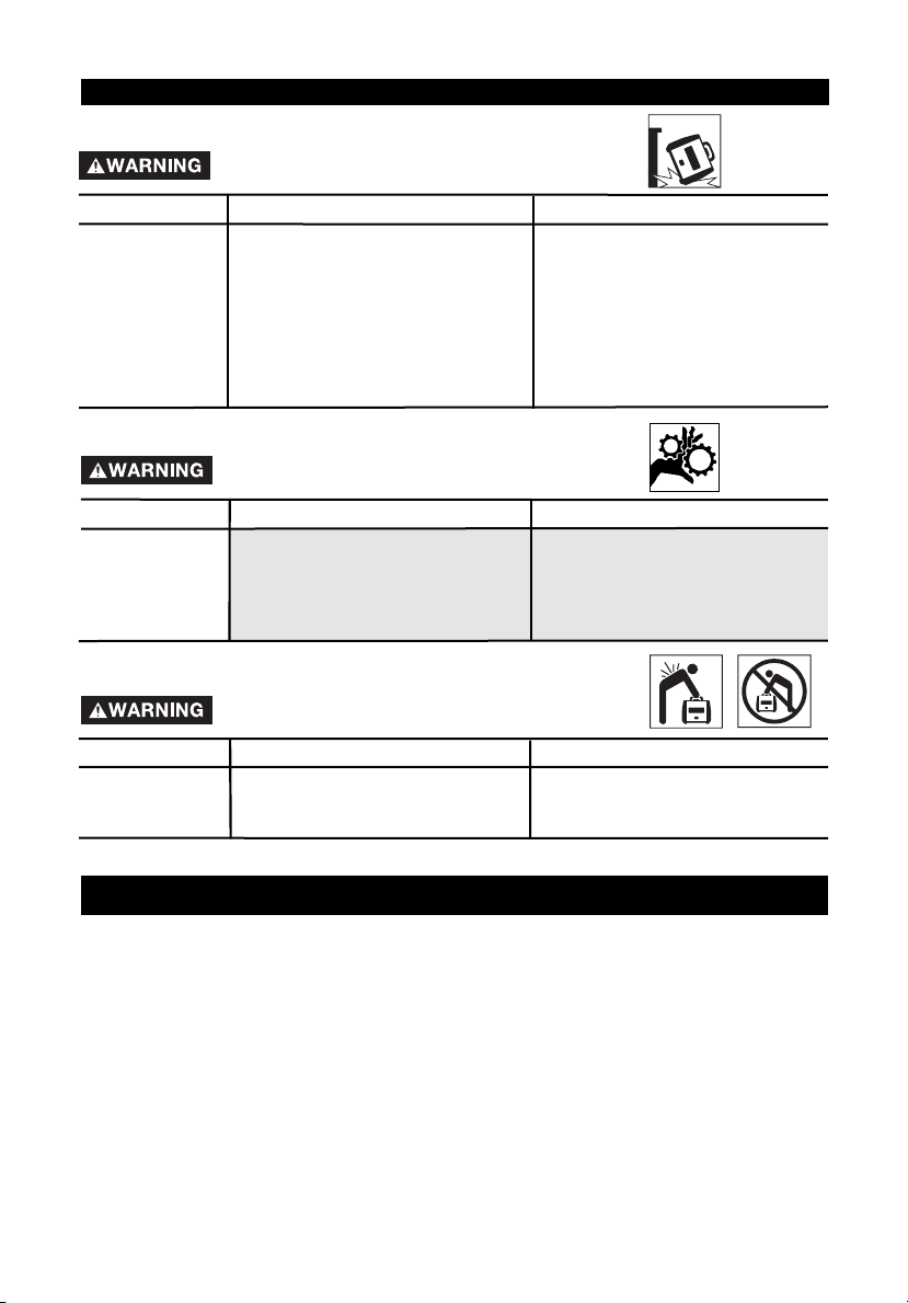
Operation of
generator in rain,
wet, icy, or
flooded
conditions.
Water is an excellent conductor
of electricity! Water which comes
in contact with electrically
charged components can
transmit electricity to the frame
and other surfaces, resulting in
electrical shock to anyone contacting them.
Operate generator in a clean, dry,
well ventilated area. Make sure
hands are dry before touching unit.
3- ENG
A04669
indicates an imminently hazardous situation which, if not avoided, will result in death
or serious injury.
indicates a potentially hazardous situation which, if not avoided, could result in
death or serious injury.
indicates a potentially hazardous situation which, if not avoided,may result in minor
or moderate injury
used without the safety alert symbol indicates potentially hazardous situation
which, if not avoided, may result in property damage.
This manual contains information that is important for you to know and understand. This
information relates to protecting YOUR SAFETY and PREVENTING EQUIPMENT PROBLEMS.
To help you recognize this information, we use the symbols below. Please read the manual and
pay attention to these sections.
SAFETY GUIDELINES / DEFINITIONS
IMPORTANT SAFETY INSTRUCTIONS
Improper operation or maintenance of this product could result in serious injury
and property damage. Read and understand all warnings and operating
instructions before using.
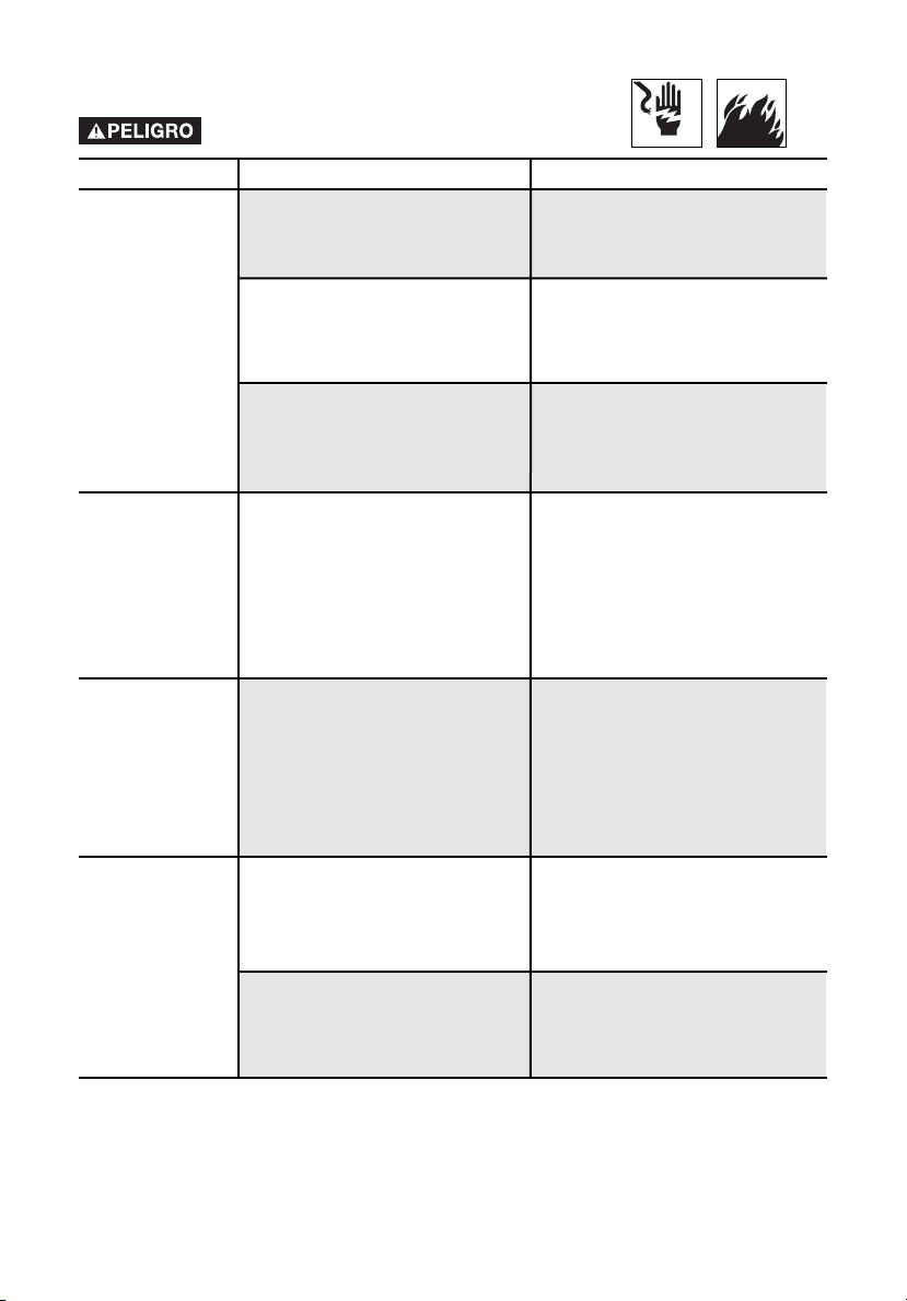
RISK OF ELECTROCUTION AND FIRE
HAZARD
WHAT CAN HAPPEN
HOW TO PREVENT IT
Attempting to
connect generator
directly to the
electrical system
of any building
structure.
Back feeding electricity through
a building’s electrical system to
the outside utility feed lines
could endanger repair persons
attempting to restore service.
Never backfeed electricity through a
structure's electrical system.
Page 4

4- ENG
A04669
Operation of unit
when damaged,
or with guards or
panels removed.
Removal of guarding could
expose electrically charged
components and result in
electrocution.
Do not operate generator with protective guarding removed.
Improper
connection of
items to
generator.
Exceeding the load capacity of
the generator by attaching too
many items, or items with very
high load ratings to it could
result in overheating of some
items or their attachment wiring
resulting in fire or electrical
shock.
Attempting to use the unit
when it has been damaged, or
when it is not functioning
normally could result in fire or
electrocution.
Read the load rating chart and instructions in the Wattage Calculation section. Make sure that the
summation of electrical loads for all
attachments does not exceed the
load rating of the generator.
Do not operate generator with mechanical or electrical problem. Have
unit repaired by an Authorized Service Center.
Use of worn,
damaged, undersized or ungrounded extension cords.
Use of ungrounded cordsets
could prevent operation of
circuit breakers and result in
electrical shock.
Always use a cordset having a
grounding wire with an appropriate
grounding plug. DO NOT use an ungrounded plug.
Use proper size (wire gauge)
cordset for application see chart in
the Assembly section of this
manual.
Contact with worn or damaged
extension cords could result in
electrocution.
Use of undersize extension
cords could result in overheating
of the wires or attached items,
resulting in fire.
Inspect extension cords before use
and replace with new cord if required.
Placing generator
on or against
highly conductive
surface, such as a
steel walkway or
metal roof.
Place generator on low conductivity surface such as a concrete slab.
Accidental leakage of electrical
current could charge conductive
surfaces in contact with the
generator.
RISK OF ELECTROCUTION AND FIRE
(Continued)
HAZARD
WHAT CAN HAPPEN
HOW TO PREVENT IT
ALWAYS operate generator a minimum of six feet from any conductive surface.
Page 5
5- ENG
A04669
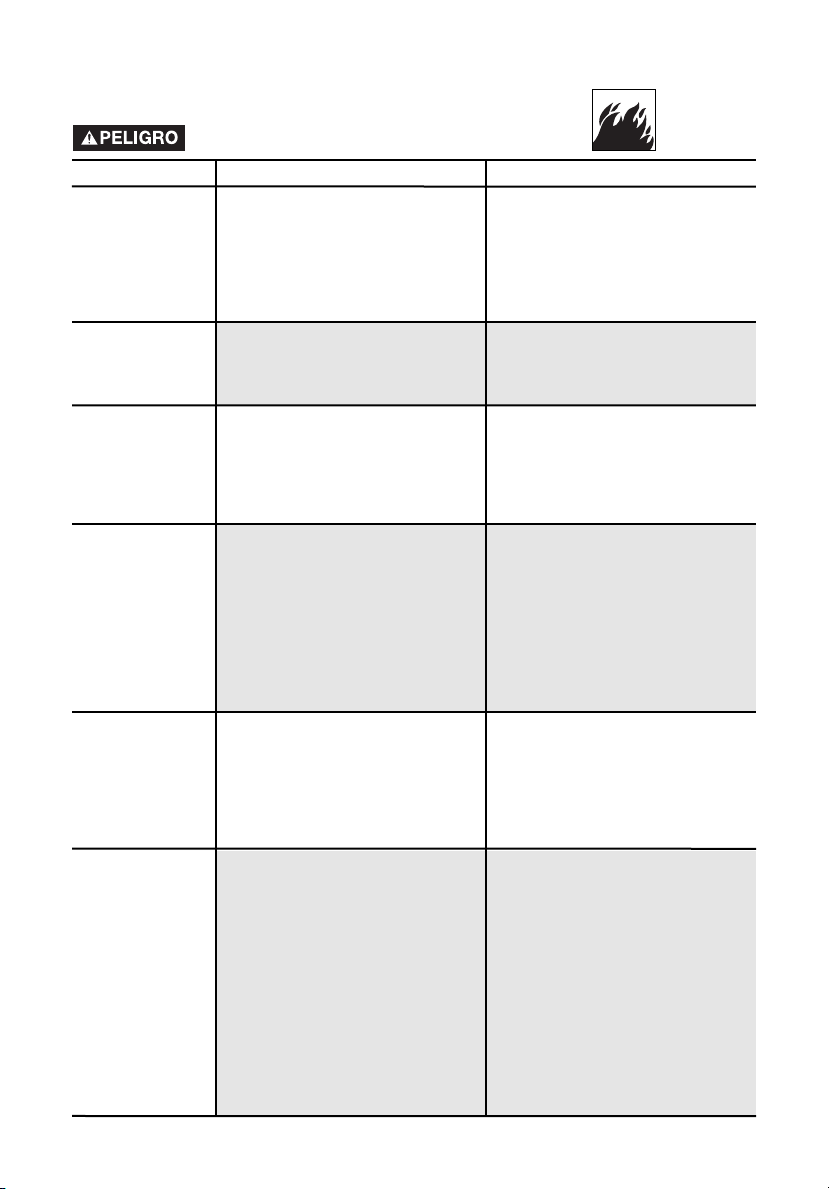
RISK OF FIRE
HAZARD
WHAT CAN HAPPEN
HOW TO PREVENT IT
Improper storage
of fuel
Improperly stored fuel could lead
to accidental ignition. Fuel
improperly secured could get into
the hands of children or other
unqualified persons.
Store fuel in a OSHA approved
container designed to hold
gasoline. Store container in secure
location to prevent use by others.
Attempting to
fill the fuel tank
while the engine
is running.
Gasoline and gasoline vapors can
become ignited by coming in
contact with hot components
such as the muffler, engine
exhaust gases, or from an
electrical spark.
Cigarettes, sparks, fires, or other
hot objects can cause gasoline or
gasoline vapors to ignite.
Turn engine off and allow it to cool
before adding fuel to the tank.
Equip area of operation with a fire
extinguisher certified to handle
gasoline or fuel fires.
Add fuel to tank in well ventilated
area. Make sure there are no
sources of ignition near the
generator.
Operate generator in a clean, dry,
well ventilated area a minimum of
four feet from any building, object
or wall. DO NOT OPERATE UNIT
INDOORS OR IN ANY CONFINED
AREA.
Materials placed against or near the
generator or operating the generator in areas where the temperature
exceeds 104° F. ambient (such as
storage rooms or garages) can interfere with its proper ventilation
features causing overheating and
possible ignition of the materials or
buildings.
Sparks, fire, hot
objects
Inadequate
ventilation for
generator
Tampering with
factory set
engine speed
settings.
Engine speed has been factory
set to provide safe operation.
Tampering with the engine speed
adjustment could result in
overheating of attachments and
could cause a fire.
Spilled fuel and its vapors can
become ignited from hot surfaces
or sparks.
Never attempt to "speed-up" the
engine to obtain more performance. Both the output voltage
and frequency will be thrown out of
standard by this practice,
endangering attachments and the
user.
Use care in filling the tank to avoid
spilling fuel. Make sure fuel cap is
secured tightly and check engine
for fuel leaks before starting
engine. Move generator away from
refueling area or any spillage
before starting engine. Allow for
fuel expansion. Keep maximum
fuel level ¼ inch below the tip of
the fuel tank. Never refuel with the
engine running.
Overfilling the fuel
tank – fuel
spillage.
Page 6
6- ENG
A04669
RISK OF UNSAFE OPERATION
HAZARD
WHAT CAN HAPPEN
HOW TO PREVENT IT
Operation of
generator in
careless manner
All sources of energy include the
potential for injury. Unsafe
operation or maintenance of your
generator could lead to serious
injury or death to you or others.
• Review and understand all of the
operating instructions and
warnings in this manual.
• Become familiar with the operation and controls of the
generator. Know how to shut it
off quickly.
• Equip area of operation with a
fire extinguisher certified to
handle gasoline or fuel fires.
• Keep children or others away
from the generator at all times.
RISK OF BREATHING - INHALATION
HAZARD
HAZARD
WHAT CAN HAPPEN
HOW TO PREVENT IT
Breathing exhaust fumes will
cause serious injury or death.
Operate generator in clean, dry,
well ventilated area. Never operate
unit in enclosed areas such as
garages, basements, storage,
sheds, or in any location occupied
by humans or animals. Keep children, pets and others away from
area of operating unit.
Gasoline
engines produce
toxic carbon
monoxide
exhaust fumes.
RISK OF INJURY AND PROPERTY
DAMAGE WHEN TRANSPORTING
GENERATOR
HAZARD
WHAT CAN HAPPEN
HOW TO PREVENT IT
Fire, Inhalation,
Damage to
Vehicle Surfaces
Fuel or oil can leak or spill and
could result in fire or breathing
hazard, serious injury or death
can result. Fuel or oil leaks will
damage carpet, paint or other
surfaces in vehicles or trailers.
If generator is equipped with a fuel
shut-off valve, turn the valve to the
off position before transporting to
avoid fuel leaks. If generator is not
equipped with a fuel shut-off valve,
drain the fuel from tank before
transporting. Transport fuel only in
an OSHA approved container.
Always place generator on a
protective mat when transporting
to protect against damage to
vehicle from leaks. Remove
generator from vehicle immediately
upon arrival at your destination.
Page 7
7- ENG
A04669
RISK OF UNSAFE OPERATION
(Continued)
HAZARD
WHAT CAN HAPPEN
HOW TO PREVENT IT
Improper raising or suspending
can cause damage to the
generator.
Always use cables, chains, or
straps rated at 2000 lbs working
load or more to raise or suspend
generator.
Operation of
voltage
sensitive appliances without a
voltage surge
protector
Any gasoline operated household
generator will incur voltage
variations causing damage to
voltage sensitive appliances or
could result in fire.
Always use a U.L. listed voltage
sensitive surge protector to
connect voltage sensitive
appliances (TV, computer, stereo,
etc.). Failure to use a U.L. listed
voltage surge protector will void
the warranty on your generator.
Notice: A multiple outlet strip is not
a surge protector. Make sure you
use a U.L. listed voltage surge protector
Raising or
suspending
generators
equipped with
lift rings
improperly
Generator could fall causing
serious injury or death to you or
others.
Always use proper connecting procedures as described in this
manual when connecting cables,
chains, or straps for raising or
suspending generators equipped
with lift rings.
Operating
generator while
suspended
Generator will not operate
properly and will cause damage to
the generator and could cause
serious injury or death to you or
others.
Never operate generator while suspended or in an unlevel position.
Always operate generate on a flat,
level surface.
Contact with hot surfaces, such
as engines exhaust components,
could result in serious burns.
RISK OF HOT SURFACES
HAZARD
WHAT CAN HAPPEN
HOW TO PREVENT IT
Contact with hot
engine and
generator
components.
During operation, touch only the
control surfaces of the generator.
Keep children away from the generator at all times. They may not be
able to recognize the hazards of
this product.
Page 8
8- ENG
A04669
SPECIFICATIONS
MODEL GM1000
HORSE POWER 2.4
RATED/SURGE WATTS 1000/1250
VOLTAGE 120V
AMPERAGE 8.3 A
PHASE SINGLE
HERTZ 60 Hz
ENGINE SPEED 3600 RPM
MAX. AMBIENT TEMP. 104° F
FUEL CAPACITY 1.2 GALLON
RUN TIME @ 50%/100% 8/6 HOURS
HAZARD
WHAT CAN HAPPEN
HOW TO PREVENT IT
HAZARD
WHAT CAN HAPPEN
HOW TO PREVENT IT
RISK OF MOVING PARTS
Never operate generator with
guarding or cover plates removed.
Avoid wearing loose fitting clothing
or jewelry which could be caught by
moving parts.
The generator contains parts which
rotate at high speed during
operation. These parts are covered
by guarding to prevent injury.
Contact with
moving parts
can result in
serious injury.
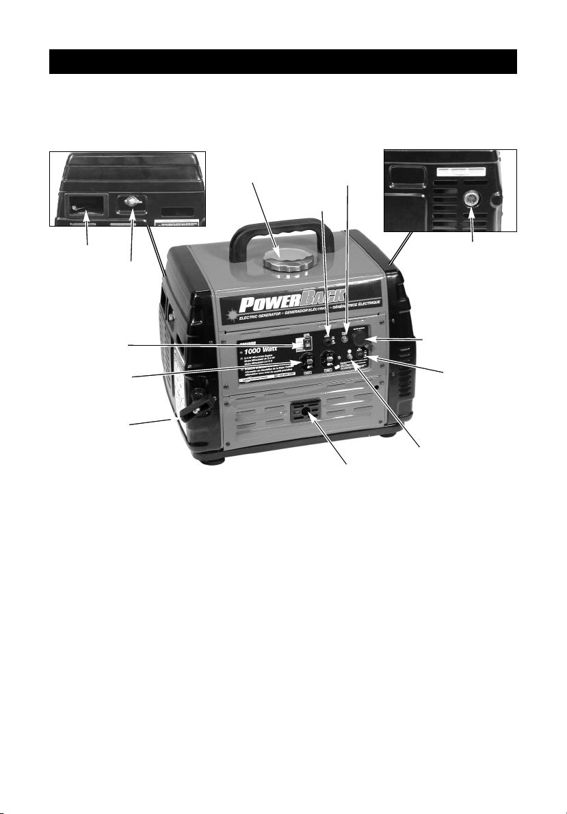
RISK FROM LIFTING
This generator is heavy and lifting it
may require assistance.
Serious injury can result from attempting to lift a heavy object.
Lifting a heavy
object.
A portable generator can fall from a
table, workbench, or roof causing
damage to the generator and could
result in serious injury or death.
Always operate generator in a
stable secure position to prevent
accidental movement of the unit.
Never operate generator on a roof
or other elevated position.
HAZARD
HAZARD
WHAT CAN HAPPEN
HOW TO PREVENT IT
RISK OF FALLING
A portable
generator can
fall from an
elevated
position causing
equipment
damage or
serious injury.
Page 9
9- ENG
A04669
NOTE: Left and right describes the
location of a part with the operator
facing the outlet panel.
REMOVE GENERATOR FROM
CARTON
• Open carton from top.
• Locate and remove the handle kit.
• Assemble the handle to the top of
the generator using the screwdriver
and screws supplied. Save the
screwdriver and spark plug wrench
for future use.
• Carefully lift generator from carton.
GROUNDING THE GENERATOR
A grounding screw is supplied on the
generator for use when required by local
electrical ordinances. Refer to article 250
of the National Electrical Code to clarify
any needed grounding information. Your
local electric company or a certified
electrician should be able to help you
with this information.
ASSEMBLY
Read this manual. Do
not attempt to operate
equipment until you have read this
Manual for Safety, Operation, and
Maintenance Instructions.
EXTENSION CORDS
When using an appliance or tool at a
considerable distance from the
generator, a 3-wire extension cord that
has a 3-blade grounding plug and a
3-slot receptacle that accepts the tool's
plug MUST be used in order to reduce
the risk of electrical shock. A cord of
adequate size must be used. Using the
following chart to determine the
minimum wire size required.
Extension Cord Wire Gauge Chart
Amperage
Cord
Length
Wire
Gauge
Size
An extension cord
that is hot to the
touch is overloaded. Repair or
replace damaged extension cords
immediately.
DO NOT connect this
generator to the main
electrical supply coming into a house.
Up to 10
amp draw
14 ga.0 to
100 ft.
Page 10
10- ENG
A04669
OPERATION
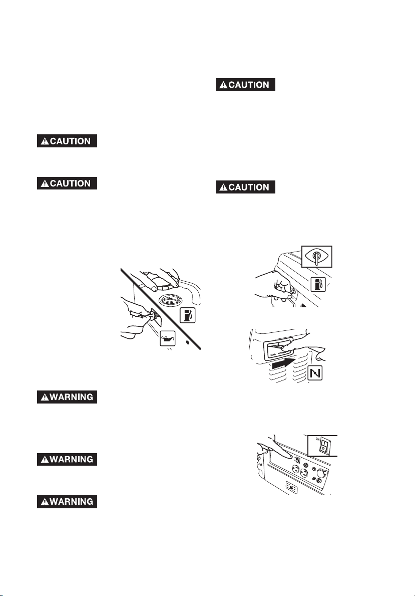
1. Engine On/Off Switch - Enables
and disables the ignition system.
2. Pilot Lamp - Indicates voltage is
being provided by generator.
3. 12V DC Outlet - Supplies voltage
to 12V DC appliances. NOTE: This
outlet is for operating 12V DC
appliances only, DO NOT use this
outlet to charge batteries.
4. Grounding Screw- This is the
attachment point for a ground wire
to an external earth ground.
5. Receptacle- 120V duplex supplies
voltage to 120V appliances.
6. Fuel Cap - Fill the fuel tank with
clean, fresh, unleaded gasoline with
a pump octane rating of 87 or
higher.
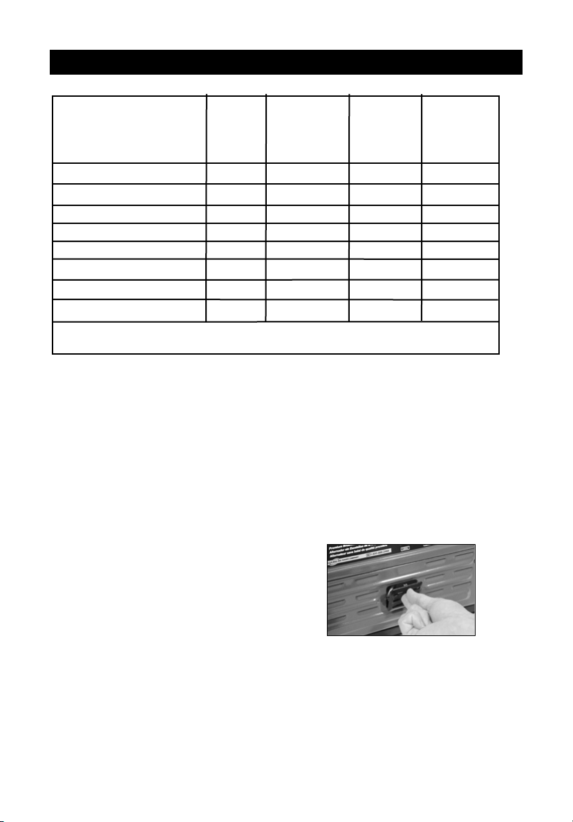
7. Circuit Breakers -
Each receptacle
has a circuit breaker to protect the generator from overloading. If the circuit
breaker trips, unplug all electrical loads
from the generator. Let the circuit breaker cool down. Push circuit breaker
button to reset.
8. Oil Fill - Fill the crankcase with
SAE 10W-30 oil.
9. Muffler Exhaust
10. Fuel Valve Lever - Opens and
closes the connection between the
fuel tank and the carburetor.
11. Choke- Opens and closes the
choke valve in the carburetor.
12. Recoil Starter
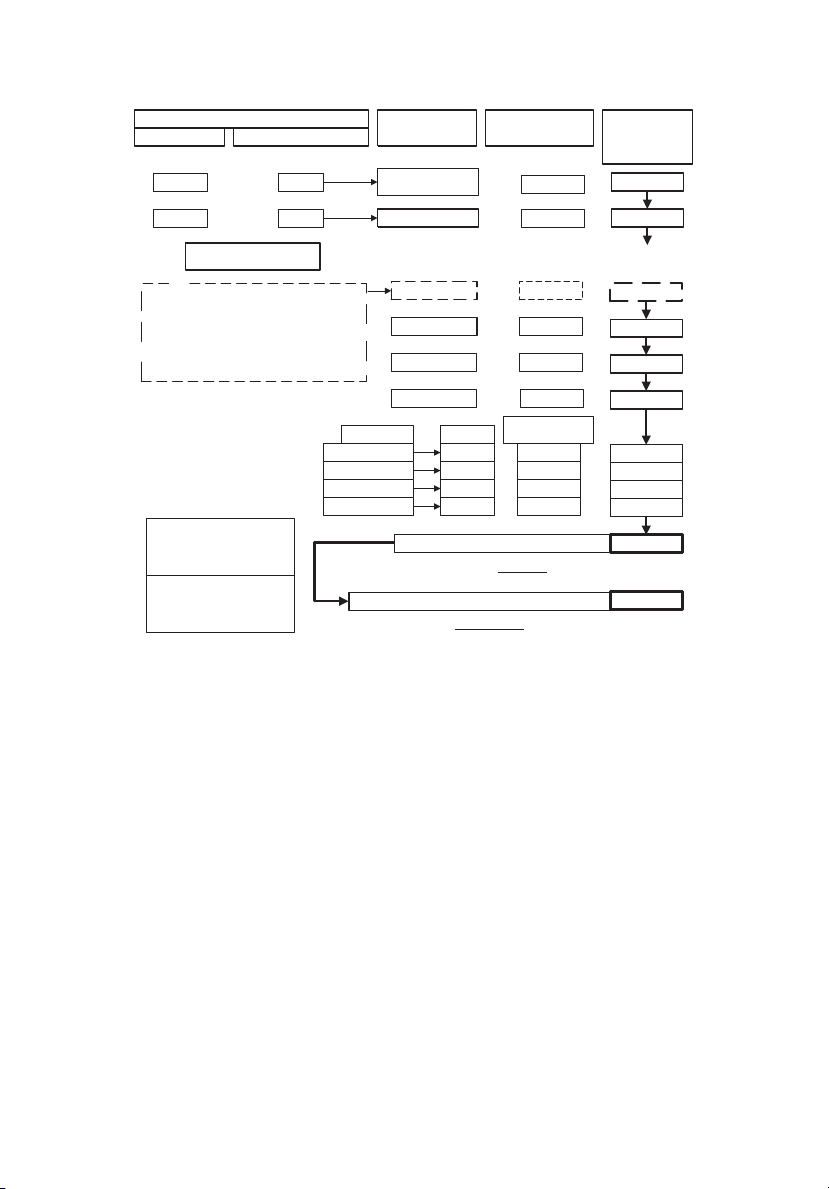
KNOW YOUR GENERATOR
Read this General Manual and Safety Rules before operation of your Generator. Compare
the illustration in your parts manual with your generator to familiarize yourself with the location of
various controls and adjustments. Save all manuals for future references.
Muffler
Exhaust (9)
Choke (11)
Fuel Valve
Lever (10)
Oil Fill (8)
12V DC
Outlet (3)
DC Circuit
Breaker (7)
Grounding
Screw (4)
Pilot
Lamp (2)
Engine
On/Off
Switch (1)
Receptacle (5)
AC Circuit
Breakers (7)
Fuel Cap (6)
Recoil
Starter (12)
Page 11
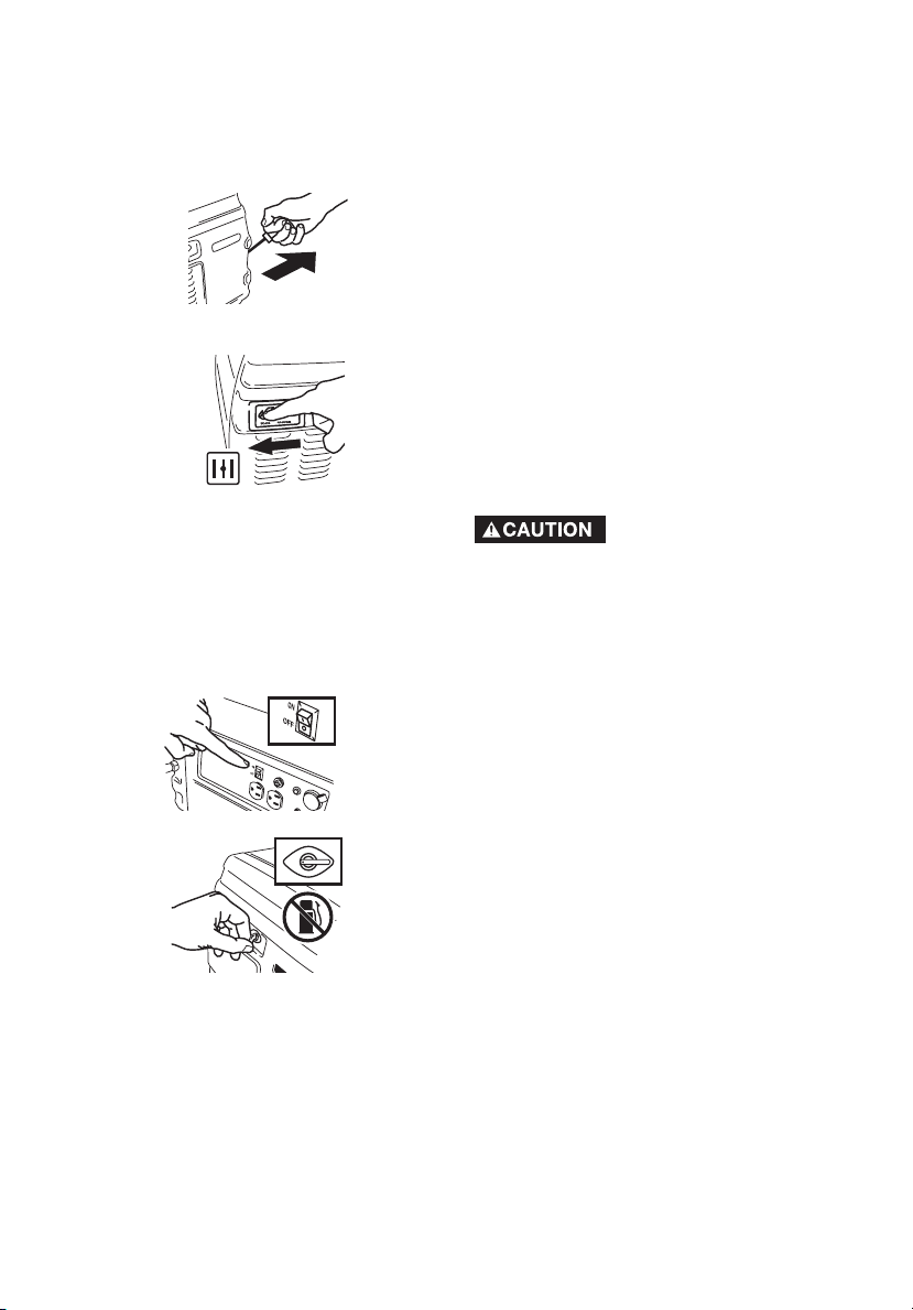
TO START THE ENGINE
1. Open the fuel shut-off valve lever.
2. Move the choke control located to
CHOKE position.
NOTE: No choke is required on warm
engines. Make sure choke is in the RUN
position on warm engine starts.
3. Move the engine ON/OFF switch to
the ON position.
11- ENG
A04669
GENERATOR CAPACITY
IMPORTANT: Exceeding the rated capacity
of your generator can result in serious damage
to your generator and connected electrical
devices. See the Wattage Calculation section
in this manual to assist you in determining the
appliances and tools that can be run with the
wattage capacity of your generator.
BEFORE START UP
This generator has been
shipped from the factory
without oil in the crankcase. Operating the
unit without oil can damage the engine.
Always check engine oil
level before every start.
Running engine low of oil or out of oil could
result in serious damage to the engine.
Follow the steps listed below before starting
generator:
1. Check engine oil. See the Maintenance
section for correct procedure.
2. Check fuel level,
fill as required.
Make sure generator is turned off
and has been
allowed time to
cool down. Use
clean, fresh, regular unleaded
gasoline with a
minimum of 87 octane. Do not mix oil
with gasoline.
Never fill fuel tank
completely. Fill tank to
1/2" below the bottom of the filler neck to
provide space for fuel expansion. Wipe
any fuel spillage from engine and
equipment before starting engine.
Never fill fuel tank
indoors. Never fill fuel
tank when engine is running or hot. Do
not smoke when filling fuel tank.
Never run engine
indoors or in enclosed,
poor ventilated areas, engine exhaust
contains carbon monoxide, an odorless
and deadly gas.
3. Make sure generator is grounded in
accordance with local requirements.
4. All electrical loads MUST be
disconnected.
Engine speed has been
factory set to provide
safe operation. Tampering with the engine
speed adjustment could result in overheating of attachments and could cause a fire.
Never attempt to "speed-up" the engine to
obtain more performance. Both the output
voltage and frequency will be thrown out of
standard by this practice, endangering attachments and the user.
You MUST unplug any
load from the generator
before starting to prevent permanent damage to any appliances.
ON
OFF
OFF
Page 12
12- ENG
A04669
CONNECTING ELECTRICAL
LOADS
1. Let engine run and warm up for five
minutes after starting with no
electrical load.
IMPORTANT: If engine speed or voltage
fluctuates with a load below 250 Watts,
move the choke control to the half
choke position.
4. Grasp handle on rope starter and
pull slowly until resistance is felt. Let
the rope rewind slowly. Pull rope
with a rapid full arm stroke. Let rope
rewind slowly. Repeat if necessary.
5. When engine starts, gradually move
the choke to the RUN position.
IMPORTANT: Allow generator to run at
no load for five minutes upon each initial
start-up to allow engine and generator
to stabilize.
STOPPING ENGINE
1. Disconnect all electrical loads.
2. Turn engine ON/OFF switch to
"OFF" position.
3. Close fuel shut-off valve lever.
Connect loads in the following manner
to prevent damage to equipment:
2. Connect inductive load equipment
first; inductive loads consist of
small hand tools and some small
appliances. Connect the items that
require the most wattage first. See
Wattage Calculation Section in this
manual.
3. Connect the lights next.
4. Voltage sensitive equipment should
be the last equipment connected to
the generator. Plug voltage sensitive
appliances such as TV's, VCR's,
microwaves, and cordless
telephones into a UL listed voltage
surge protector, then connect the
UL listed voltage surge protector to
the generator.
Failure to connect and
operate equipment in
this sequence can cause damage to
equipment and will void the warranty
on your generator.
Follow the wattage calculation table in
the Wattage Calculation section of this
manual. Overloading the generator
will cause power fluctuations and can
damage equipment and appliances.
DeVilbiss Air Power Company will only
be responsible for damage to
customer's equipment when the
generator is determined to be
defective. This determination will only
be made by an authorized
representative of DeVilbiss Air Power
Company and this decision will be
final. DeVilbiss Air Power Company
reserves the right to inspect the
electrical connections at the
customer's site of operation and test
the generator for proper operation
before any determination of liability is
made. Failure to maintain the
equipment or wiring for inspection will
void any claim for damages by the
customer. DeVilbiss Air Power
Company will not be responsible for
equipment damaged as a result of
voltage surges, improper operation or
improper installation of the generator.
ON
OFF
Page 13
13- ENG
A04669
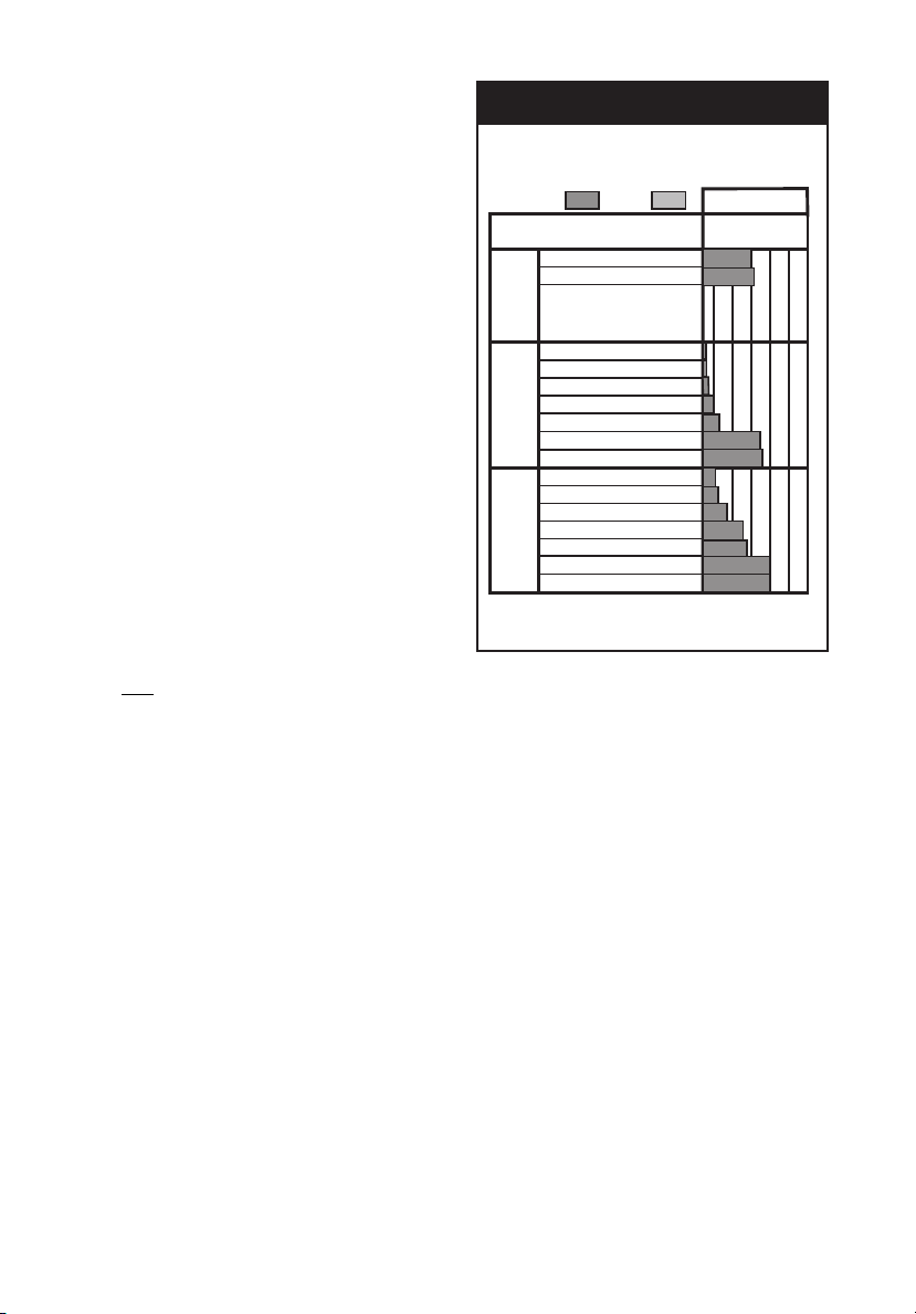
Note 1: Change oil after first two (2) operating hours and every 50 operating hours
thereafter, more often if operated in extremely dusty or dirty conditions.
Note 2: Check oil after 5 hours of operation.
Note 3: Every 100 hours of operation or once a year.
CUSTOMER RESPONSIBILITIES TABLE
MAINTENANCE TASK
Before
each
use
Every 25
Hours of
Every
Season
Every 50
Hours of
Every
Season
Every 100
Hours of
Every
Season
Check Spark Plug
Prepare unit for storage if it is to remain
idle for more than 30 days.
MAINTENANCE
Check oil level
Change oil
Clean Air Filter Assembly
Prepare Unit for Storage
See Note 2
X
See Note 1
X
X
See Note 3
Clean Fuel Valve Bowl
X
Clean Fuel Filter
X
Clean Fuel Tank Filter
X
Clean Muffler Screen
X
GENERAL RECOMMENDATIONS
The warranty of the generator does not
cover items that have been subjected to
operator abuse or negligence. To
receive full value from the warranty,
operator must maintain the generator as
instructed in this manual.
GENERATOR MAINTENANCE
Your generator should be kept clean and
dry at all times. The generator should
not be stored or operated in
environments that include excessive
moisture, dust or any corrosive vapors. If
these substances are on the generator,
clean with a cloth or soft bristle brush.
Do not use a garden hose or anything
with water pressure to clean the generator. Water may enter the cooling air slots
and could possibly damage the rotor,
stator and the internal windings of the
gen head.
ENGINE
To Check Oil
1. Shut down engine and place on a
level surface.
2. Remove the oil filler cap/dipstick
cover.
Page 14
3. Remove filler cap/dipstick.
4. Place a suitable container under the
oil drain hole in the frame.
5. Remove the drain plug and allow
the engine oil to drain into the
container.
NOTE: Please dispose of used motor oil
in a manner that is compatible with the
environment. It is recommended to take
used oil in a sealed container to your local
recycling center or service station for
reclamation. Do not throw it in the trash
or pour it on the ground or down a drain.
6. Replace oil drain plug.
7. With the engine in a level position,
fill to the edge of the oil filler hole
with the SAE 10W-30 oil.
NOTE: Other viscosities shown in the
chart in the "To Check Oil" paragraph
may be used.
8. Replace the oil filler cap/dipstick
securely.
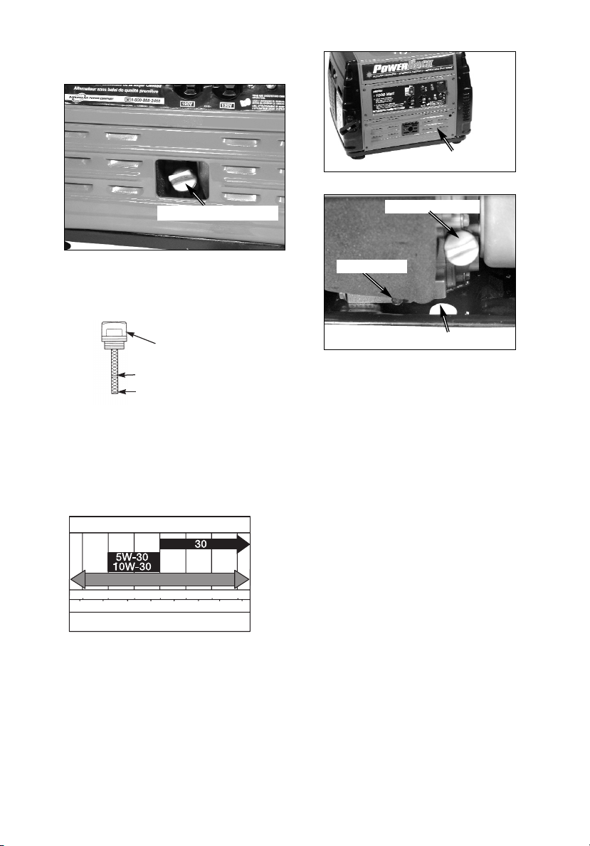
To Change Oil
Drain the engine oil when the engine is
warm. Warm oil drains quickly and
completely.
1. Stop engine as described in the
Operation section.
2. Remove the bottom panel on the
control panel side of the unit.
Remove Bottom Panel
Filler Cap/Dipstick
Oil Drain Plug
Oil Drain Hole
14- ENG
A04669
3. Remove the oil filler cap/dipstick
and wipe it clean.
4. Insert and remove the filler
cap/dipstick without screwing it into
the filler neck. Check the oil level
shown on the dipstick.
5. If the oil level is low, fill to the edge
of the oil filler hole with the SAE
10W-30 oil.
NOTE: Other viscosities shown in the
chart may be used when the average
temperature in your area is within the
recommended range.
Oil Filler cap/dipstick
Oil Filler
Cap/Dipstick
Upper Limit
Lower Limit
SAE Viscosity Grades
**
*
Synthetic 5W-30, 10W-30
-20 0 20 40 60 80 100
F
-30 -20 -10 0 10 20 30 40
C
STARTING TEMPERATURES RANGE
ANTICIPATED BEFORE NEXT OIL CHANGE
32
Page 15
15- ENG
A04669
Air Filter
A dirty air cleaner will restrict air flow to
the carburetor and cause poor engine
performance. Inspect the filter each time
the engine is operated. Clean the filter
more frequently if the engine is operated
in very dusty areas.
NOTICE: Operating the engine without a
filter will allow dirt to enter the engine,
causing rapid engine wear. This type of
damage is not covered under the
warranty.
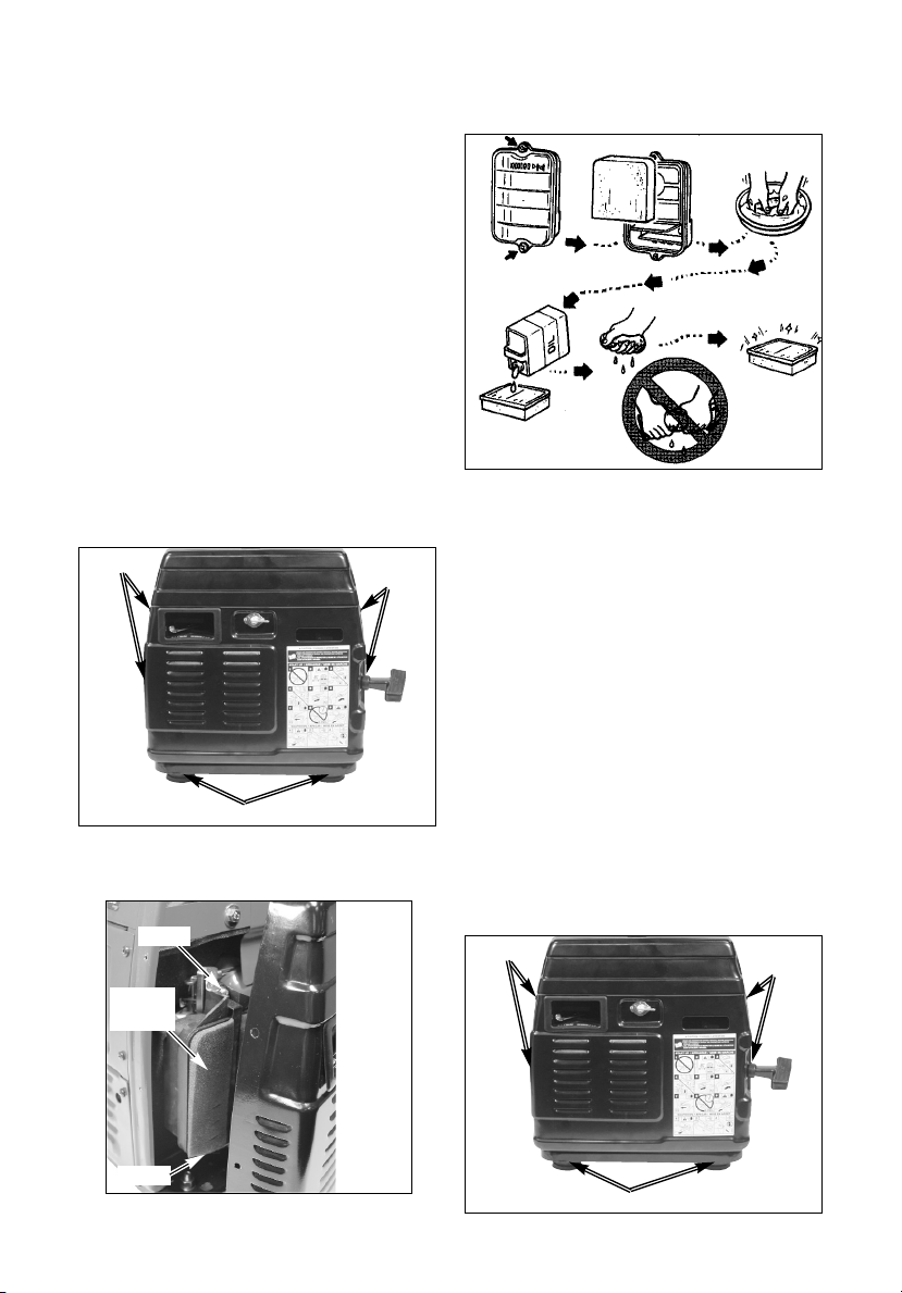
Cleaning
1. Remove the four screws securing
the sides of the panel and the two
fasteners with isolators securing the
bottom of the panel. Carefully
remove the panel noting that the
fuel filter and recoil starter will be
attached to the panel.
2. Remove the screws holding the
foam element in place.
Screws
Screws
Fasteners with isolators
3. Wash element in liquid detergent
and water. Air dry thoroughly.
4. Add clean engine oil to element and
press out excess, DO NOT wring or
twist element.
5. Replace element and secure in
place.
6. Replace and secure panel.
Screw
Screw
Foam
Element
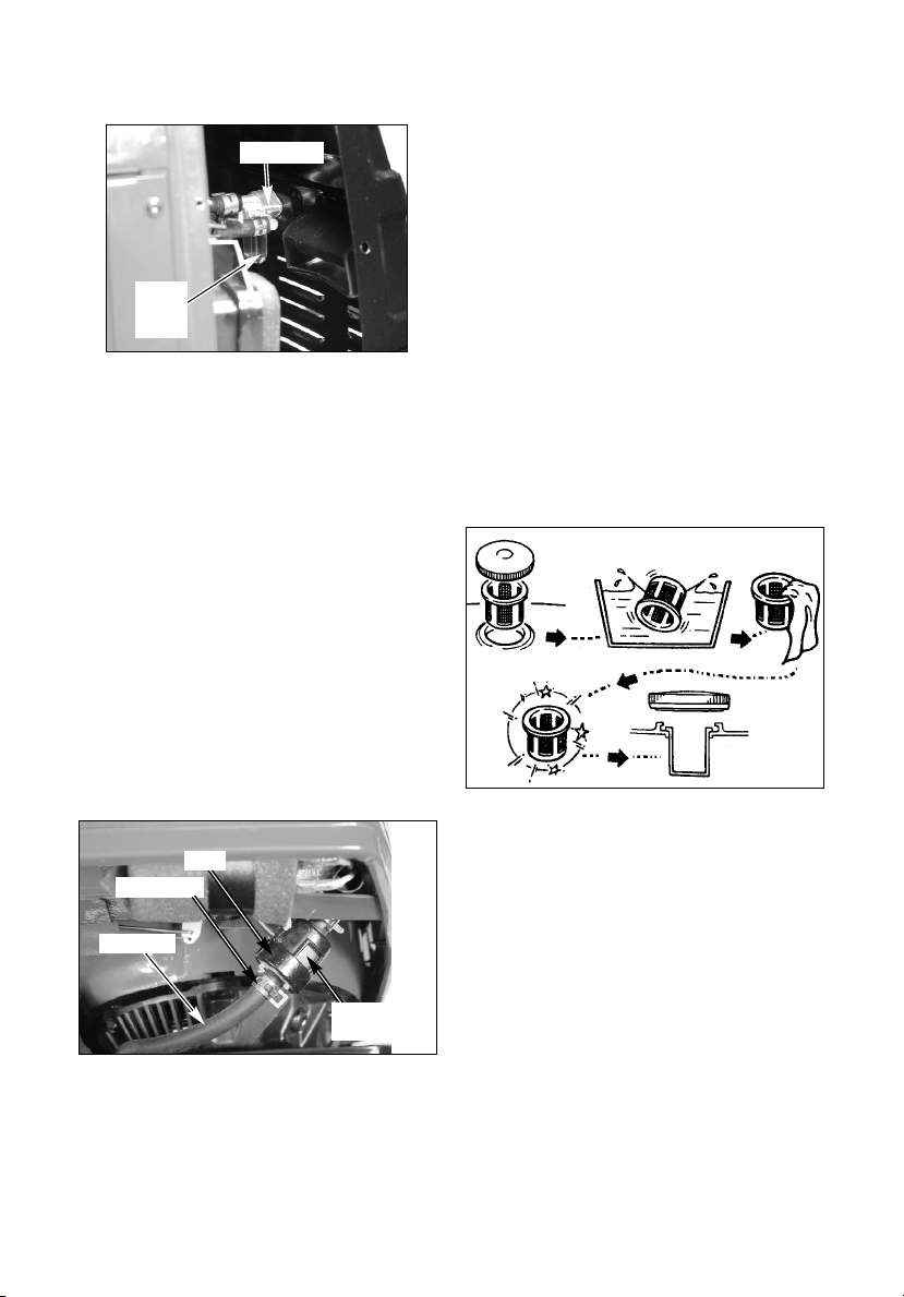
Fuel Valve Bowl
Cleaning
1. Stop engine as described in the
Operation section.
2. Place the fuel valve lever in the OFF
position.
3. Remove the four screws securing
the sides of the panel and the two
fasteners with isolators securing the
bottom of the panel. Carefully
remove the panel noting that the
fuel filter and recoil starter will be
attached to the panel.
Screws
Screws
Fasteners with isolators
Page 16
Muffler Screen
Cleaning
1. Stop engine as described in the
Operation section.
2. On the exhaust end of the unit,
remove the four screws securing
the sides of the panel and the two
fasteners with isolators securing the
bottom of the panel. Carefully pull
panel away from the unit noting the
insulation is attached to the panel.
16- ENG
A04669
Fuel Tank Filter
Cleaning
1. Stop engine as described in the
Operation section.
2. Remove gas cap and remove the
fuel tank filter.
3. Clean with solvent. Wipe off excess
solvent and replace fuel tank filter
into tank.
Fuel Filter
NOTE: It is recommended to run all the
gasoline from the tank before changing
or cleaning the fuel filter.
1. Stop engine as described in the
Operation section.
2. Place the fuel valve lever in the OFF
position.
3. Remove the recoil end panel as
described in the Fuel Valve Bowl
paragraph.
4. The fuel line can be removed from
the fuel filter cover by squeezing the
fuel clamp and sliding it up the fuel
line.
5. After removing the fuel line unscrew
the cap on the fuel filter cover.
NOTE: Do not loose rubber washer
from fuel filter cover cap.
Fuel Filter
Cover
4. Unscrew and remove the fuel valve
bowl.
5. Clean and replace fuel valve bowl.
Tighten securely.
6. Replace and secure panel.
Fuel Valve
Fuel
Valve
Bowl
4. Replace gas cap.
Fuel Clamp
Cap
Fuel Line
6. The fuel filter can now be removed
to clean or replace.
7. Place new or cleaned filter into
cover.
8. Press rubber washer into fuel filter
cap and screw cap into fuel filter
cover body.
9. Reconnect fuel line.
10. Replace and secure panel.
Page 17
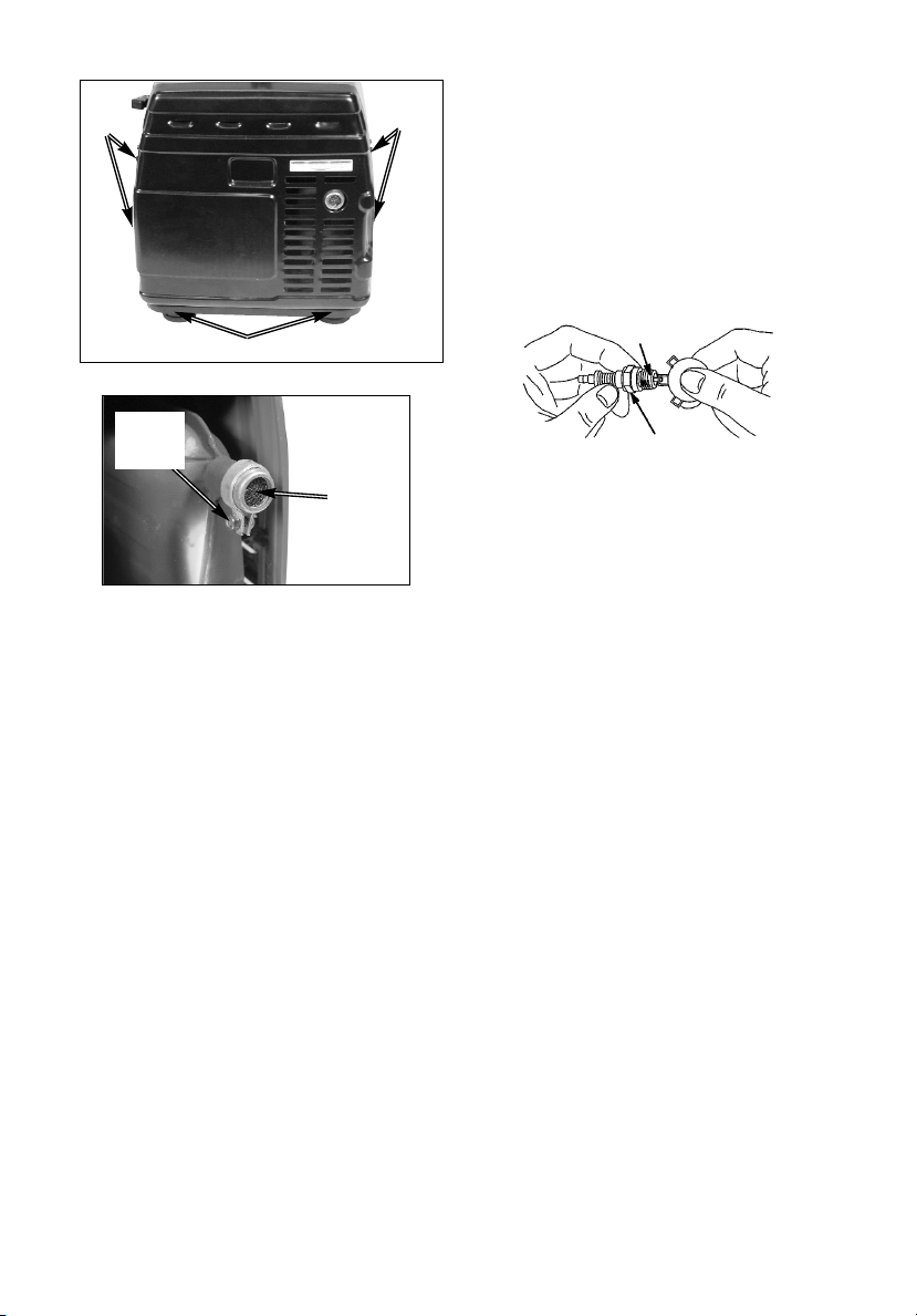
3. Remove the muffler screen.
4. Clean the muffler screen using a
wire brush.
5. Replace muffler screen and secure
in place.
6. Replace and secure panel.
17- ENG
A04669
Screws
Screws
Fasteners with isolators
Muffler
Screen
Remove
Screw
and Nut
Replace Spark Plug
Change the spark plug every 100 hours
of operation or once each year,
whichever comes first. This will help your
engine to start easier and run better.
NOTE: Use the spark plug wrench and
screwdriver supplied to remove spark
plug. The spark plug is found under the
top panel opposite the controls.
Resistor
.030" (0.76 MM)
Wire Gauge
NOTE:
Standard spark plug: BPR4ES (NGK)
Spark Plug Gap: 0.7-0.8 mm
(0.028 -0.031 in)
Page 18

18- ENG
A04669
If you are going to store your generator
for more than 30 days, use the following
information as a guide to prepare the
generator for storage.
Never store generator
with fuel in the tank
indoors or in enclosed, poorly ventilated areas, where fumes can reach
an open flame, spark, or pilot light as
on a furnace, water heater, clothes
dryer, or other gas appliances.
ENGINE PREPARATION
1. Add fuel stabilizer to fuel tank to
minimize the formation of fuel gum
deposits during storage.
2. Run engine at least 10 minutes after
adding stabilizer to allow it to enter
the fuel system.
3. Shut off engine.
4. Disconnect the spark plug wire and
remove the spark plug.
5. Add one teaspoon of oil through the
spark plug hole.
STORAGE
6. Place rag over spark plug hole and
pull the recoil a few times to
lubricate the combustion chamber.
7. Replace the spark plug, but do not
connect the spark plug wire.
NOTE: If a fuel stabilizer is not used, all
gasoline must be drained from the tank
and carburetor to prevent gum deposits
from forming on these parts and causing
possible malfunction of the engine.
IMPORTANT: If gasoline is removed
from the tank, oil needs to be added to
prevent rust from forming in the tank:
1. Pour a cup of SAE 10W-30 oil into
the gas tank.
2. With assistance from another
person, shake or roll the unit so the
oil covers the complete gas tank.
3. Drain off excess oil.
GENERATOR
• Clean the generator as outlined in
the Maintenance Section on this
manual.
• Check that cooling air slots and
openings on generator are open
and unobstructed.
Page 19
19- ENG
A04669
WATTAGE CALCULATIONS
Never exceed the rated capacity of your generator. Serious damage to the
generator or appliance could result from an overload.
1. Starting and running wattage requirements should always be calculated when
matching a generators wattage capacity to the appliance or tool.
2. There are two types of electrical appliances that can be powered by your
generator:
A. Items such as radios, light bulbs, television sets, and microwaves have a
"resistive load". Starting wattage and running wattage are the same.
B. Items such as hand tools that use an electrical motor have an "inductive
load". Inductive load appliances and tools require approximately 2 to 3
times the listed wattage for starting
the equipment. This initial load only
lasts for a few seconds on start-up but is very important when figuring
your total wattage to be used.
C. Always start your largest electric motor first, and then plug in other
items, one at a time.
NOTE: On 120-volt loads the maximum starting wattage should NOT exceed
1250 watts.
IMPORTANT
DETERMINING WATTAGE REQUIREMENTS
Before operating this generator list all of the appliances and/or tools that are going
to operate at the same time. (Then determine the starting wattage requirements and
the running wattage requirements by following example and/or refer to household
wattage calculator.)
1. First total the running wattage of all appliances and/or tools that will be
operated at the same time.
Running W
atts Starting Watts
Example 1:
Lights = 100 Watts 0
Television = 300
Watts 0
TOTAL = 400 Watts 0
2. Next the starting wattages of any appliances and/or tools that will start and
stop during operation.
Running W
atts Starting Watts
Example 2:
Blender 400 W
atts 800 Watts
TOTAL = 400 Watts 800 Watts
3. The running wattage of examples 1 & 2 totals 800 watts. The starting wattage
of the blender is 800 watts which is 400 watts more than the running watts.
Take this difference of 400 starting watts from the blender and add to the total
running watts of 800.
Example 3: 400 Starting Watts
800 Running W
atts
TOTAL =1200 Total Watts
Generator must have a maximum capacity of at least 1200 watts.
Page 20
20- ENG
A04669
STARTING WATTAGE
REQUIREMENTS
1. Some appliances and tools will list
on the motor nameplate the
starting and running voltage and
amperage requirements. Use the
following formula to convert
voltage and amperage to wattage:
Volts X Amp = Watts
Example: 120 volts x 10 amps =
1200 watts
2. To determine the approximate
starting wattage requirement for
most appliances and tools with
inductive type motors, multiply the
wattage that was calculated by 2 to
3 times to assure adequate
generator capacity. If the
nameplate information is not available use the values on the
following chart as a guide.
3. Remember that the starting and
running wattage for resistive loads
are the same. (Example: a 100
watt light bulb requires only 100
watts to start.) Most resistive loads
will
be listed in wattage.
Application Guide
To select the right generator for your
needs, total the wattageof the items to
be run at the same time.
Run
Electric Appliance
3/8" Hand Drill
Jigsaw
Contractor
Light Bulb
Small Fan
Radio
Home Security
ReliefRecreational
Television
Emergency
Hair Dryer
Microwave
12V DC Battery Charger
Radio
Slow Cooker
Electric Blanket
Electric Skillet
Coffee Maker
Blender
The wattage ratings shown are averages.
Wattage requirements may vary with different
brands of appliances.
Start
Wattage
100
250
500
1000
1500
Page 21
21- ENG
A04669
HOUSEHOLD WATTAGE CALCULATOR
DEVICES WITH HIGH STARTING (INDUCTIVE)LOADS
RUN WATTS
500
400
TIMES (X) START FACTOR
x
x
2
2
CAUTION !!
DO NOT CONNECT VOLTAGE SENSITIVE ELECTRONIC
EQUIPMENT (TV SET, COMPUTER, ETC.) DIRECTLY TO
YOUR GENERATOR. IF YOU USE THE GENERATOR TO
POWER SENSITIVE EQUIPMENT YOU MUST USE A U.L.
LISTED VOLTAGE SURGE PROTECTOR.
NOTICE: FAILURE TO USE A U.L. LISTED VOLTAGE
SURGE PROTECTOR WILL DAMAGE YOUR
EQUIPMENT AND VOID YOUR WARRANTY.
*FOR PRODUCTS NOT
LISTED REFER TO
CALCULATION
INSTRUCTIONS
**AVERAGE VALUES -
ACTUAL INDIVIDUAL
DEVICE VOLTAGES MAY
BE HIGHER OR LOWER
LIGHTING
60 WATT BULBS
75 WATT BULBS
100 WATT BULBS
300 WATT BULBS
WATTAGE RATING OF YOUR GENERATOR
THIS TOTAL MUST BE GREATER THAN YOUR HOUSEHOLD WATTAGE LOAD
APPLIANCE OR
LOAD DEVICE*
CORDED HAND
TOOL
BLENDER
TELEVISION
MICROWAVE
HAIR DRYER
SMALL FAN
WATTS
60
75
100
300
TYPICAL DEVICE
WATTAGE**
=
1000
=
800
=
300
800
=
800
=
42
=
TIMES NUMBER
OF BULBS
x
x
x
x
=
=
=
=
=
=
=
=
=
=
ELECTRIC LOAD GRAND TOTAL
THIS TOTAL MUST BE LESS THAN YOUR GENERATOR RATING
TOTAL
CAUTION !!
Page 22

22- ENG
A04669
TROUBLESHOOTING GUIDE
PROBLEM
CAUSE
CORRECTION
Engine will not
start
1. Low on fuel or oil.
2. Engine On/Off switch in
Off position.
3. Faulty spark plug.
4. Choke in wrong position.
5. Fuel valve lever in closed
position
6. Unit loaded during
start-up.
1. Add fuel or oil.
2. Place in the ON position
3. Replace spark plug.
4. Adjust choke accordingly.
5. Open fuel valve lever.
6. Remove load from unit.
1. Faulty receptacle.
1. Have Service Center replace.
2. Circuit breaker kicked
out.
2. Depress and reset.
3. Defective capacitor.
3. Have Service Center replace
capacitor.
4. Faulty power cord.
4. Repair or replace cord.
7. Spark plug wire loose.
7. Attach wire to spark plug.
No electrical
output
1. Overload
1. Reduce load.
2. Faulty cords or
equipment
2. Check for damaged, bare, or
frayed wires on equipment.
Replace.
Repeated
circuit breaker
tripping
1. Generator overloaded.
1. Reduce load.
2. Insufficient ventilation.
2. Move to adequate supply of
fresh air.
Generator
overheating
8. Fuel line clogged.
8. Clean fuel line and fuel filter.
9. Faulty ignition system.
9. Consult a Service Center.
Page 23

23- ENG
A04669
AVAILABLE REPAIR PARTS
Part No. Description
Z-A05449 Fuel Cap
Z-A05451 Air Filter
Z-A05453 Fuel Shut Off Valve
Z-A05454 Fuel Filter
Z-A05458 Control Panel Assembly
Z-A05459 Generator Assembly
Z-A05460 Engine Assembly
Z-A05455 Oil Fill Cap
Z-A05457 Spark Arrestor
Z-A05456 Capacitor
Page 24

LIMITED WARRANTY
DeVilbiss Air Power Company warrants to the original purchaser who uses the product in a consumer
application (personal, residential or household usage) that all products covered under this warranty are free
from defects in material and workmanship for one year from the date of purchase. All products covered by
this limited warranty which are used in commercial applications (i.e., income producing) are warranted to be
free of defects in material and workmanship for 90 days from the date of original purchase. Products
covered under this warranty include air compressors, air tools, service parts, pressure washers, and
generators.
DeVilbiss Air Power Company will repair or replace, at DeVilbiss' option, products or components which
have failed within the warranty period. Service will be scheduled according to the normal work flow and
business hours at the service center location, and the availability of replacement parts. All decisions of
DeVilbiss Air Power Company with regard to this limited warranty shall be final.
This warranty gives you specific legal rights, and you may also have other rights which vary from state to
state.
RESPONSIBILITY OF ORIGINAL PURCHASER (initial User):
• To process a warranty claim on this product, DO NOT return it to the retailer. The product must be
evaluated by an Authorized Warranty Service Center. For the location of the nearest Authorized Warranty
Service Center call 1-800-888-2468, 24 hours a day, 7 days a week or visit our web site @ devap.com.
• Retain original cash register sales receipt as proof of purchase for warranty work.
• Use reasonable care in the operation and maintenance of the product as described in the Owners
Manual(s).
• Deliver or ship the product to the nearest Authorized Warranty Service Center. Freight costs, if any, must
be paid by the purchaser.
• Air compressors with 60 and 80 gallon tanks will be inspected at the site of installation. Contact the
nearest Authorized Warranty Service Center that provides on-site service calls for service call
arrangements.
• If the purchaser does not receive satisfactory results from the Authorized Warranty Service Center, the
purchaser should contact DeVilbiss Air Power Company.
THIS WARRANTY DOES NOT COVER:
• Merchandise sold as reconditioned, used as rental equipment, or floor or display models.
• Merchandise that has become damaged or inoperative because of ordinary wear, misuse*, cold, heat,
rain, excessive humidity, freeze damage, use of improper chemicals, negligence, accident, failure to
operate the product in accordance with the instructions provided in the Owners Manual(s) supplied with
the product, improper maintenance, the use of accessories or attachments not recommended by
DeVilbiss Air Power Company, or unauthorized repair or alterations.
* An air compressor that pumps air more than the recommended duty cycle during a one hour period
may be considered misuse.
• Repair and transportation costs of merchandise determined not to be defective.
• Costs associated with assembly, required oil, adjustments or other installation and start-up costs.
• Expendable parts or accessories supplied with the product which are expected to become inoperative or
unusable after a reasonable period of use, including but not limited to sanding disks or pads, saw and
shear blades, grinding stones, springs, chisels, nozzles, o-rings, air jets, washers and similar
accessories.
• Merchandise sold by DeVilbiss Air Power Company which has been manufactured by and identified as
the product of another company, such as gasoline engines. The product manufacturer's warranty, if any,
will apply.
• ANY INCIDENTAL, INDIRECT OR CONSEQUENTIAL LOSS, DAMAGE, OR EXPENSE THAT MAY
RESULT FROM ANY DEFECT, FAILURE OR MALFUNCTION OF THE PRODUCT IS NOT COVERED
BY THIS WARRANTY. Some states do not allow the exclusion or limitation of incidental or
consequential damages, so the above limitation or exclusion may not apply to you.
• IMPLIED WARRANTIES, INCLUDING THOSE OF MERCHANTABILITY OR FITNESS FOR A
PARTICULAR PURPOSE, ARE LIMITED TO ONE YEAR FROM THE DATE OF ORIGINAL
PURCHASE. Some states do not allow limitations on how long an implied warranty lasts, so the above
limitations may not apply to you.
213 Industrial Drive • Jackson, TN 38301-9615
Telephone: 1-800-888-2468
FAX: 1-800-888-9036
A04669
24- ENG
Page 25

25- SP
A04669
Lea el manual del operador. No opere el equipo hasta haber leído las
instrucciones Seguridad, Operación y Mantenimiento en el Manual del
Operador.
Esta unidad no está equipada con un cortachispas en el tubo de
escape. Operar esta unidad en California constituye una violación de
las secciones 130050 y/o 4442 y 4443 a menos que esté provista de un
cortachispas de acuerdo a lo definido en la sección 4442 y que esté en buen estado de
funcionamiento. El cortachispas también se requiere en algunas tierras del Servicio Forestal
del Gobierno de los EE.UU. y también puede requerirse bajo otros estatutos y ordenanzas.
Los gases que escapan de esta unidad contienen químicos, que en
ciertas cantidades, se conoce que causan cáncer, defectos de
nacimiento u otras lesiones reproductivas.
INFORMACIÓN GENERAL Y DE SERVICIO PARA EL CONSUMIDOR
• Lea y siga estas instrucciones para el uso y mantenimiento apropiado.
• Tómese el tiempo ahora para registrar su generador en www.devap.com.
• Si se le presenta cualquier problema o nedcesita asistencia, llámenos gratis al
1-800-888-2468, de lunes a sábado de 8:00 a.m. a 6:00 p.m. Hora Estándar
del Centro.
• Si requiere servicio o comprar un repuesto, cualquiera de nuestros muchos
Servicentros Autorizados para Garantía convenientemente ubicados están
equipados para proveer todos los servicios amparados por la garantía o fuera de
ella.
• Para información sobre la ubicación del Servicentro Autorizados para Garantía
más cercano, llame gratis a nuestra línea 1-800-888-2468 las 24 horas de los 7
días de la semana o visite nuestro sitio web: www.devap.com.
• Para el servicio de garantía, conserve el comprobante de pago por la compra.
• Lea y entienda todas las advertencias de seguridad.
• No opere esta unidad sin antes haber leido y comprendido todas las
instrucciones de seguridad, operación y mantenimiento de este manual.
INFORMACIÓN DE SEGURIDAD PARA EL CONSUMIDOR
¡NO DEVUELVA ESTA UNIDAD AL LUGAR DONDE LA COMPRÓ! PARA LAS
OPCCIONES DE SERVICIO, LLAME AL 1-800-888-2468
Page 26

26- SP
A04669
La operación inapropiada de esta unidad puede causar lesiones serias y
daños a la propiedad. Lea y entienda todas las advertencias de
seguridad e instrucciones de operación antes de usar esta unidad.
Operación de un
generador bajo
lluvia, ambientes
mojados, con
hielo o
condiciones
inundadas.
¡El agua es un excelente
conductor de la electricidad! El
agua que entra en contacto con
componentes cargados de
electricidad puede transmitir la
electricidad al bastidor y a otras
superficies causando choque
eléctrico a cualquiera que esté en
contacto con ellos.
Opere el generador en un área
limpia, seca y bien ventilada.
Asegúrese de tener las manos
secas antes de tocar la unidad.
Indica una situación peligrosa inminente que si no se evita causará muerte o
lesiones serias.
Indica una situación potencialmente riesgosa que si no se evita puede causar
lesiones serias o muerte.
Indicates a potentially hazardous situation which, if not avoided,may result in
minor or moderate injury
Usado sin el símbolo de alerta indica una situación potencialmente riesgosa
que si no se evita puede causar daños materiales.
Este manual contiene información que es importante que usted sepa y entienda. Esta
información se relaciona con la protección de SU SEGURIDAD y la PREVENCIÓN DE
PROBLEMAS AL EQUIPO. Para ayudarle a entender esta información usamos los siguientes
símbolos. Por favor leer este manual y prestar atención especial a estas secciones.
PAUTAS DE SEGURIDAD - DEFINICIONES
INSTRUCCIONES IMPORTANTES DE SEGURIDAD
RIESGO DE ELECTROCUCIÓN E INCENDIO
RIESGO
¿QUÉ PUEDE SUCEDER?
¿CÓMO EVITARLO?
Intento de
conectar el
generador
directamente al
sistema eléctrico
de cualquier
construcción.
Retroalimentar electricidad por
el sistema eléctrico de una
construcción hacia la red publica
puede poner en peligro a las
personas que estén tratando de
restaurar el servicio.
Nunca retroalimente electricidad al
sistema eléctrico de una edificación.
Page 27
27- SP
A04669
Operación de la
unidad dañada o
sin las cubiertas
o paneles
protectores.
La remoción de las cubiertas
protectoras puede exponer los
componentes con carga
eléctrica y causar
electrocución.
No opere el generador sin las
cubiertas protectoras.
Conexión
inadecuada de
artefactos al
generador.
Exceder la capacidad de salida
de un generador conectándole
demasiados artefactos o
artefactos de gran demanda
puede hacer que algunos de
éstos se recalienten, que su
cableado se incendie o cause
choque eléctrico.
Intentar usar la unidad dañada
o cuando no funciona
normalmente, puede causar
incendio o electrocución.
Lea la cartilla de Demandas de
Carga e Instrucciones en la sección
Cálculo de Wataje. Asegúrese que
la suma total del wataje de todos
los artefactos eléctricos
conectados al generador no
exceda la capacidad de salida del
generador.
No opere el generador si tiene
problemas mecánicos o eléctricos.
Haga reparar la unidad en un
servicentro autorizado.
Uso de
cordones de
extensión
gastados,
dañados, subdimensionados
o no
conectados a
tierra.
El uso de cordones de extensión
sin conexión a tierra puede evitar
que los interruptores de circuito
se abran y causar choque
eléctrico.
Siempre use un cordón que tenga
un alambre para conexión a tierra y
enchúfelo a un tomacorriente con
conexión a tierra. NO USE un
enchufe sin conexión a tierra.
Use un cordón con alambres del
calibre adecuado para el uso que
se le va a dar. Refiérase a la
cartilla en la sección Ensamblaje de
este manual.
El contacto con cordones de
extensión gastados o dañados
puede causar electrocución.
El uso de cordones de extensión
subdimensionados puede causar
recalentamiento de los alambres
o artefactos conectados,
causando un incendio.
Inspeccione los cordones de
extensión antes de usarlos y
cámbielos por nuevos si se
requiere.
Colocación de un
generador sobre
o contra una
superficie
altamente
conductiva como
una pasarela de
acero o un techo
de metal.
Coloque el generador sobre una
superficie de baja conductividad,
como un piso de concreto.
SIEMPRE opere un generador a
una distancia mínima de 1,80m. (6')
de cualquier superficie conductiva.
La fuga accidental de corriente
eléctrica puede cargar las
superficies conductivas en
contacto con el generador.
RIESGO DE ELECTROCUCION E INCENDIO
(Continuación)
RIESGO
¿QUÉ PUEDE SUCEDER?
¿CÓMO EVITARLO?
Page 28
28- SP
A04669
RIESGO DE INCENDIO
Almacenaje
inapropiado del
combustible.
El combustible mal almacenado
puede conducir a un incendio
accidental. El combustible
guardado en un lugar inseguro
puede caer en manos de los niños
u otras personas no calificadas.
Guarde el combustible en un
contenedor diseñado para gasolina
aprobado por OSHA. Guarde el
contenedor en un lugar seguro para
evitar su uso por otras personas.
Intento de llenar
el tanque de
combustible
con el motor
funcionando.
La gasolina y sus vapores pueden
incendiarse al hacer contacto con
componentes calientes como el
motor, su escape o sus gases o
una chispa eléctrica.
Los cigarrillos, chispas, fuegos u
otros objetos calientes pueden
hacer que la gasolina o sus
vapores se inflamen.
Apague el motor y espere a que se
enfríe antes de echarle
combustible al tanque. Provea al
área de operación con un extintor
de incendios certificado para
gasolina u otros incendios de
combustibles.
Llene el tanque con combustible
en un área bien ventilada.
Asegúrese que no existan fuentes
de encendido cerca del generador.
Opere el generador en un lugar
limpio, seco y bien ventilado y
alejado por lo menos 1,2m (4') de
cualquier construcción, objeto o
pared. NO OPERE EL
COMPRESOR EN INTERIORES NI
EN ÁREAS CONFINADAS.
Los materiales colocados contra o
cerca del generador o su operación
en áreas con temperatura
ambiental superior a 40°C (104°F)
(como en bodegas de
almacenamiento o garajes) pueden
interferir con sus dispositivos de
ventilación, causar recalentamiento
y un probable incendio de los
materiales o la edificación.
Chispas, fuego,
objetos calientes.
Ventilación
inadecuada
para el
generador.
Alteración de la
graduación de
velocidad del
motor hecha en
fábrica.
La velocidad del motor se ha
graduado en fábrica para proveer
una operación segura. Adulterar
esta graduación puede causar
recalentamiento de los artefactos
conectados y un incendio.
El combustible derramado y sus
vapores pueden incendiarse por
contacto con superficies
calientes o chispas.
Nunca intente "acelerar" el motor
para obtener mayor rendimiento.
Tanto el voltaje como la frecuencia
de la corriente de salida se saldrán
de la norma y pondrán en peligro
los artefactos conectados y
también al usuario.
Tenga cuidado al llenar el tanque para
evitar derramar combustible. Antes de
arrancar el motor, cerciórese que la tapa
del tanque de combustible esté ajustada
en forma segura, revise que el motor no
tenga fugas de combustible y aleje la
unidad del lugar donde se le llenó de
combustible o de cualquier derrame.
Deje lugar en el tanque para la expansión
del combustible. Mantenga el nivel
máximo del combustible 2,5cm (1")
debajo de la boca de llenado del tanque.
Nunca rellene combustible con el motor
encendido.
Sobrellenado de
combustible en el
tanque. Derrame
de combustible.
RIESGO
¿QUÉ PUEDE SUCEDER?
¿CÓMO EVITARLO?
Page 29

29- SP
A04669
RIESGO DE OPERACIÓN INSEGURA
La operación del
generador en
forma
descuidada.
Todas las fuentes de energía
tienen el potencial de causar
lesiones. La operación o
mantenimiento inseguro del
generador puede conducir a
lesiones serias o muerte del
operador o de otros.
• Lea y comprenda todas las
operaciones de instrucción y
advertencias en este manual.
• Familiarícese con la operación y
los controles del generador; y
como apagarlo en forma rápida.
• Provea al área de operación con
un extintor de incendios
certificado para incendios de
gasolina o combustibles.
• Mantenga a los niños y a otras
personas alejadas del generador
en todo momento.
RIESGO A LA RESPIRACIÓN O
INHALACIÓN
Respirar los gases del escape
puede causar lesiones serias o
muerte.
Opere el generador en un área
limpia, seca y bien ventilada; nunca
lo opere en áreas cerradas como
garajes, sótanos, almacenes,
casetas, cobertizos ni en lugares
ocupados por seres humanos o
animales. Mantenga a los niños y
las mascotas alejados del área de
operación.
Los motores a
gasolina
producen
monóxido de
carbono toxico
por los gases
del escape.
RIESGO DE LESIONES Y DAÑOS A LA
PROPIEDAD AL TRANSPORTAR EL
GENERADOR
Incendio,
inhalación,
daños a las
superficies del
vehículo.
El combustible o el aceite se
pueden fugar o derramarse y
causar un incendio o riesgo a la
respiración, lesiones serias o
muerte. Estas fugas pueden
dañar las alfombras, pintura y
otras superficies de los vehículos
o remolques.
Si el generador está equipado con
una válvula de cierre de combustible,
ciérrela antes de transportar la unidad
y evitar así las fugas. Si el generador
no tiene una válvula de cierre de
combustible, drene el combustible del
tanque antes de transportar la unidad.
Transporte el combustible únicamente
en un contenedor aprobado por
OSHA. Siempre coloque el generador
sobre una alfombra protectora
cuando lo transporte para así evitar
daños al vehículo por las fugas.
Desmonte el generador del vehículo
inmediatamente que llegue a su
destino.
RIESGO
¿QUÉ PUEDE SUCEDER?
¿CÓMO EVITARLO?
RIESGO
¿QUÉ PUEDE SUCEDER?
¿CÓMO EVITARLO?
RIESGO
¿QUÉ PUEDE SUCEDER?
¿CÓMO EVITARLO?
Page 30

30- SP
A04669
RIESGO DE OPERACIÓN INSEGURA
(Continuación)
El izaje, levantamiento o
suspensión inapropiada, puede
causar daños al generador.
Para elevar o suspender un
generador Siempre use cables,
cadenas o eslingas con capacidad
para 900 Kg. (2000 Lb.) de carga o
más.
Operación de
artefactos
sensibles a
sobrecargas de
voltaje sin un
protector de
sobrecargas.
Cualquier generador de corriente
a gasolina doméstico incurrirá en
variaciones de voltaje que causen
daño a artefactos sensibles a
estas variaciones o pueden
causar incendio.
Para operar artefactos sensibles a
las variaciones de voltaje (TV,
computadoras, estéreos, etc.)
siempre conéctelos a un protector
de sobrecargas de voltaje
certificado por U.L. Si no se usa
un protector de sobrecarga de
voltaje certificado por U.L., se
anulará la garantía del generador.
Nota: Una barra de tomacorrientes
múltiples no es un protector de
sobrecargas. Asegúrese de usar
un protector de sobrecargas de
voltaje certificado por U.L.
Izaje o
levantamiento
inapropiado de
generadores
provistos de
anillos de
levantamiento.
El generador se podría caer y
causar lesiones serias o muerte a
usted o a otras personas.
Siempre siga los procedimientos
de conexión apropiados descritos
en este manual cuando se
conecten cables, cadenas o
eslingas para elevar o suspender
generadores equipados con anillos
de levantamiento.
Operating
generator while
suspended.
El generador no funcionará
apropiadamente, se dañará y
podría causarle lesiones serias o
muerte a usted o a otros.
Nunca opere un generador
mientras esté suspendido o en una
posición desnivelada. Siempre
opere el generador sobre una
superficie plana nivelada.
El contacto con superficies
calientes como los componentes
del escape del motor, puede
causar quemaduras serias.
RIESGO DE SUPERFICIES CALIENTES
Contacto con
componentes
calientes del
motor y del
generador.
Durante la operación, sólo toque
las superficies de control del
generador. Mantenga a los niños
alejados del generador en todo
momento. Ellos pueden no
reconocer los riesgos de esta
máquina.
RIESGO
¿QUÉ PUEDE SUCEDER?
¿CÓMO EVITARLO?
RIESGO
¿QUÉ PUEDE SUCEDER?
¿CÓMO EVITARLO?
Page 31

31- SP
A04669
ESPECIFICACIONES
MODELO: GM1000
CABALLAJE: 2,4
TAJE CAPACIDAD/SOBRECARGA: 1000/1250
VOLTAJE: 120V
AMPERAJE: 8,3A
FASES: 1 (UNA)
CICLOS: 60 HZ
VELOCIDAD DEL MOTOR: 3600 RPM
TEMPERATURA AMBIENTAL MÁXIMA: 40°C (104°F)
CAPACIDAD DE COMBUSTIBLE: 4,5 L (1,2 GALONES)
TIEMPO DE OPERACIÓN A 50%/100%: 8/6 HORAS
RIESGO DE PIEZAS MOVIBLES
Nunca opere el generador sin las
guardas o cubiertas protectoras.
Evite usar ropa o joyas sueltas que
puedan atraparse en las piezas
movibles.
El generador contiene piezas que
rotan a alta velocidad durante su
operación. Estas piezas están
cubiertas con guardas protectoras
para evitar lesiones.
Las piezas
movibles
pueden causar
lesiones serias.
RIESGOS POR LEVANTAMIENTO
Este generador es pesado y se
requiere ayuda para levantarlo.
El intento de levantamiento de
objetos pesados puede causar
lesiones serias.
Levantamiento
de objetos
pesados.
Un generador portátil puede caerse
de una mesa, banco de trabajo o
techo dañándose y pudiendo
causar lesiones serias o muerte.
Siempre opere el generador en una
posición estable y segura para
evitar movimientos accidentales de
la unidad. Nunca opere el
generador sobre un techo ni otra
posición elevada.
RIESGO
RIESGO DE CAÍDA DE OBJETOS
Un generador
portátil puede
caerse de una
posición
elevada y
dañarse o
causar lesiones
serias.
RIESGO
¿QUÉ PUEDE SUCEDER?
¿CÓMO EVITARLO?
RIESGO
¿QUÉ PUEDE SUCEDER?
¿CÓMO EVITARLO?
RIESGO
¿QUÉ PUEDE SUCEDER?
¿CÓMO EVITARLO?
Page 32

32- SP
A04669
NOTA: Las indicaciones de izquierda
y derecha describen la ubicación de
las piezas con el operador mirando al
panel de salida.
EXTRACCIÓN DEL GENERADOR
DE SU CAJA
• Abra la caja por arriba.
• Ubique y extraiga el juego del
manubrio.
• Instale el manubrio en la parte
superior del generador con el
entornillador y los tornillos
suministrados. Conserve el
entornillador y la llave para bujías
para uso futuro.
• Levante el generador
cuidadosamente para sacarlo de la
caja.
CONEXIÓN DEL GENERADOR A
TIERRA
El generador viene provisto de un tornillo
para conectarlo a tierra donde las
ordenanzas locales lo requieran. Para
mayor información sobre las
necesidades de conexión a tierra,
refiérase al artículo 250 del Código
Eléctrico Nacional (EE.UU.). La
compañía de suministro eléctrico local o
un electricista calificado pueden
ayudarle con esta información.
ENSAMBLAJE
Lea este manual.
No intente operar
esta unidad hasta haber leído las
instrucciones de seguridad,
operación y mantenimiento
contenidas en este manual.
CORDONES DE EXTENSIÓN
Para reducir el riesgo de choque
eléctrico, cuando opere un artefacto o
herramienta eléctrica a una distancia
considerable del generador, DEBE usar
un cordón de extensión de 3 alambres
con enchufe de 3 espigas para conexión
a tierra y con un tomacorriente de 3
ranuras que acepte el enchufe del
artefacto o herramienta. Debe usarse un
cordón de las dimensiones adecuadas.
Refiérase a la cartilla a continuación para
determinar las dimensiones mínimas de
los alambres requeridos.
Calibres de Alambres de
Cordones de Extensión
Amperaje
Largo
del
Cordón
Calibre del
Alambre
Un alambre de
extensión que se
sienta caliente al tacto, está
sobrecargado. Repare o cambie los
cordones de extensión dañados
inmediatamente.
No conecte este
generador a la
entrada del suministro eléctrico de la
casa.
Hasta 10 amperios
de demanda
14
0 a 30m
(100')
Page 33

33- SP
A04669
OPERACIÓN
1. Interruptor: Activa y desactiva el sistema
de encendido.
2. Luz piloto: Indica que el generador está
proveyendo voltaje.
3. Tomacorriente de 12V CD: Suministra
voltaje de corriente directa de 12 voltios a
los artefactos. NOTA: Este tomacorriente
es tan sólo para operar artefactos de
corriente directa de 12 voltios. NO es para
cargar baterías.
4. Tornillo para conexión a tierra: Este es el
punto donde se conecta el alambre para
conexión a tierra externa.
5. Tomacorriente: Tomacorriente doble para
proveer voltaje a artefactos de 120V.
6. Tapa de combustible: Cuando se llene el
tanque de combustible use gasolina sin
plomo, limpia y fresca de un surtidor de 87
octanos o más.
7. Interruptores de circuito: Cada
tomacorriente tiene un interruptor de
circuito para proteger el generador contra
sobre demandas. Si éste se abre (salta),
desconecte todos los artefactos
enchufados al generador. Espere que el
interruptor de circuito de enfríe y oprima
su botón de reactivación.
8. Toma de aceite: Rellene el carter con
aceite SAE10W-30.
9. Tubo de escape
10. Palanquita de la válvula de
combustible: Abre y cierra la conexión
entre el tanque de combustible y el
carburador.
11. Estrangulador (choke): Abre y cierra la
válvula de estrangulamiento del
carburador.
12. Cordón arrancador
FAMILIARÍCESE CON EL GENERADOR
Lea este manual general y las reglas de seguridad antes de operar el generador.
Compare las ilustraciones de las piezas en este manual con las del generador para
familiarizarse con la ubicación de los diversos controles y regulaciones. Conserve
todos los manuales para referencia futura.
Salida del
escape (9)
Estrangulador
(choke) (11)
Palanquita de
la válvula de
combustible
(10)
Toma de aceite (8)
Tomacorriente de
12V CD (3)
Interruptor
de circuito
de CD (7)
Tornillo para
conexión a
tierra (4)
Luz
piloto (2)
Interruptor (1)
Tomacorriente
de 110V CA (5)
Interruptor de
circuito de CA (7)
Tapa del tanque
de combustible (6)
Cordón
arrancador
(12)
Page 34

34- SP
A04669
PARA ARRANCAR EL MOTOR
1. Abra la válvula de corte de combustible
moviendo la palanquita.
2. Mueva la palanca de estrangulamiento
(choke) a la posición cerrada
NOTA: Si el motor está caliente, no se
requiere mover la palanca de
estrangulamiento (choke) a la posición
cerrada. Asegúrese que esta palanca esté
en la posición de operación cuando se
arranque un motor que esté caliente.
3. Mueva el interruptor a la posición de
encendido "ON"
CAPACIDAD DEL GENERADOR
IMPORTANTE: Exceder la capacidad del
generador puede causar daños serios al
generador y a los artefactos eléctricos
conectados. Vea la sección Cálculo de
Wataje en este manual para ayudarle a
determinar los artefactos y herramientas que
puede hacer funcionar con la capacidad del
wataje de su generador.
ANTES DE COMENZAR
Este generador se ha
despachado de fábrica
sin aceite en el carter. Operar la unidad sin
aceite puede dañar el motor.
Siempre revise el nivel
del aceite antes de
comenzar. Operar el motor con poco o nada
de aceite puede causar daños serios al motor.
Siga los pasos a continuación antes de
arrancar el generador:
1. Revise el aceite del motor. Refiérase a la
sección Mantenimiento en este manual
para el procedimiento correcto.
2. Revise que el
combustible esté al
nivel requerido.
Asegúrese que el
generador esté
apagado y que se
haya esperado
suficiente tiempo
para que se enfríe. Use gasolina regular
limpia, fresca sin plomo de mínimo 87
octanos. No mezcle aceite con la gasolina.
Para dejar suficiente
espacio para la
expansión del combustible, nunca llene el
tanque completamente, sólo hasta 13mm
(1/2") por debajo del cuello de la toma.
Limpie el combustible que pueda haberse
derramado del motor y el equipo antes de
arrancar el motor.
Nunca llene el
tanque en ambientes
interiores. Nunca llene el tanque cuando el
motor esté funcionando o caliente. No fume
al llenar el tanque de combustible.
Nunca haga
funcionar el motor
en interiores ni en áreas cerradas o con
poco ventilación porque los gases del
escape del motor contienen monóxido de
carbono y otros gases inodoros mortales.
3. Asegúrese que el generador esté
conectado a tierra de acuerdo a los
reglamentos locales.
4. DEBE desconectar todos los artefactos.
La velocidad del motor
se ha regulado en la
fábrica para proveer una operación segura.
La alteración de la velocidad del motor
puede causar sobrecalentamiento de los
artefactos conectados e incendio. Nunca
intente "acelerar" el motor para obtener
mayor rendimiento. Tanto el voltaje como
la frecuencia de la corriente de salida se
saldrán de la norma y harán peligrar los
artefactos conectados y al usuario.
Para evitarle daños
permanentes a
los
artefactos conectados al generador, DEBE
desenchufarlos del generador antes de
arrancarlo.
ON
OFF
OFF
Page 35

35- SP
A04669
4. Agarre el mango de la cuerda del
arrancador y tire de él lentamente hasta
sentir una resistencia. Deje que la
cuerda se enrolle lentamente. Tire la
cuerda en forma rápida y firme. Deje que
la cuerda se enrolle lentamente. Repita
si fuese necesario.
5. Cuando el motor arranque, mueva
gradualmente la palanquita del
estrangulador (choke) a la posición
abierta.
IMPORTANTE: Después de cada arranque
inicial, permita que el generador funcione sin
carga por 5 minutos para que el motor y el
generador se estabilicen.
APAGADO DEL MOTOR
1. Desconecte todos los artefactos que
están enchufados al generador.
2. Apague el motor moviendo el interruptor
a la posición "OFF".
3. Cierre la válvula de corte de combustible
moviendo la palanquita.
CONEXIÓN DE ARTEFACTOS
ELÉCTRICOS
1. Deje que el motor funcione y se caliente
por 5 minutos sin carga después de
arrancar.
IMPORTANTE: Si la velocidad del motor o el
voltaje fluctuasen con una demanda menor a
250 watts, mueva el control de
estrangulamiento (choke) a la posición del
medio. Conecte los artefactos de la
siguiente forma para evitarle daños al
equipo.
2. Conecte los equipos con carga inductiva
primero. Estos son herramientas
eléctricas de mano y algunos artefactos
domésticos pequeños. Conecte primero
los que demandan mayor wataje. Vea la
sección Cálculo de Wataje en este
manual.
3. Luego conecte las luces.
4. Los equipos sensibles a las variaciones
de voltaje deben conectarse al generador
al final. Estos son los televisores,
videograbadoras, hornos de microondas
y teléfonos inalámbricos que deben
conectarse a un protector de sobrecarga
de voltaje aprobados por U.L., el que a
su vez se conecta al generador.
Si no enchufa los
artefactos al generador
en la secuencia indicada, puede dañar los
artefactos y el generador y se anularán las
garantías.
Siga lo indicado en la cartilla en la sección
Cálculo de Wataje de este manual.
Sobrecargar el generador con mayor
demanda hará fluctuar el voltaje del
generador y puede dañar los equipos o
artefactos conectados a éste. DeVilbiss
Air Power Company sólo será responsable
por daños al equipo del cliente cuando se
determine que el generador está
defectuoso. Esta determinación sólo la
hará un representante autorizado de
DeVilbiss Air Power Company y su
decisión será final. DeVilbiss Air Power
Company se reserva el derecho de
inspeccionar las conexiones eléctricas en
el domicilio del cliente donde se operó la
unidad y probar el generador para
determinar lo adecuado de su operación
antes de determinar la responsabilidad.
No mantener los artefactos o el cableado
para la inspección anulará cualquier
reclamo del cliente por daños. DeVilbiss
Air Power Company no se responsabiliza
por daños a los equipos como resultado
de sobrecargas de voltaje, operación o
instalación inadecuada del generador.
ON
OFF
Page 36

36- SP
A04669
Nota 1: Cambie el aceite después de las primeras dos (2) horas de operación y de ahí
en adelante después de cada 50 horas de operación o más frecuentemente si se opera
en condiciones extremadamente polvorosas o sucias.
Nota 2: Revise el aceite después de 5 horas de operación.
Nota 3: Cada 100 horas de operación o una vez al año
RESPONSABILIDADES DEL CLIENTE
TAREAS DE
MANTENIMIENTO
Antes de
Cada
Uso
Cada 25
hrs. de
cada
temporada
Cada 50
hrs. de
cada
temporada
Cada 100
hrs. de
cada
temporada
Inspeccionar la bujía
Preparar la unidad para almacenaje si va a
permanecer inactiva por más de 30 días.
MANTENIMIENTO
Revisar el nivel de aceite
Cambiar el aceite
Limpiar el conjunto del filtro de aire
Preparar la unidad para el
almacenaje
Vea la Nota 2
X
Vea la Nota 1
X
X
Vea la Nota
3
Limpiar la taza de la válvula de
combustible
X
Limpiar el filtro de combustible
X
Limpiar el filtro del tanque de
combustible
X
Limpiar la malla del escape
X
RECOMENDACIONES GENERALES
La garantía del generador no cubre piezas
que han sufrido daños por maltrato o
negligencia del operador. Para recibir todas
las coberturas de la garantía, el operador
debe mantener el generador de acuerdo a
las instrucciones de este manual.
MANTENIMINETO DEL GENERADOR
El generador debe mantenerse limpio y seco
en todo momento y no debe guardarse ni
operarse en ambientes excesivamente
húmedos, polvorientos ni con vapores
corrosivos. Si estas substancias cayesen
sobre el generador, límpielas con una toalla
o cepillo de cerdas blandas. No use una
manguera de jardín ni agua a presión para
limpiar el generador porque el agua podría
entrar por las ranuras para el aire de
enfriamiento y dañar el rotor, el estator y el
embobinado del cabezal del generador.
MOTOR
Para revisar el aceite
1. Apague el motor y colóquelo sobre
una superficie nivelada.
2. Quite la tapa de la toma de aceite
(que tiene una varilla medidora).
Page 37

37- SP
A04669
3. Saque la tapa de la toma de aceite
4. Coloque un contenedor adecuado
bajo el orificio de drenaje de aceite
que está en el bastidor.
5. Saque el tapón de drenaje y
permita que el aceite del motor
drene al contenedor.
NOTA: Deseche el aceite usado del
motor en una forma compatible con el
medio ambiente. Se recomienda llevar el
aceite usado en un contenedor sellado al
centro local de reciclaje o estación de
servicio para que lo reciclen. No arrojarlo
a la basura ni echarlo a la tierra ni al
desagüe.
6. Reinstale el tapón del drenaje de
aceite.
7. Con el motor en posición nivelada,
rellene con aceite SAE10W-30
hasta el borde del orificio de la
toma de aceite
NOTA: Se pueden usar aceites de otras
viscosidades indicadas en la cartilla de
la sección "Revisión del Aceite".
8. Reinstale y ajuste bien la tapa de la
toma de aceite.
Cambio de aceite
Drene el aceite del motor cuando éste
se encuentre tibio. El aceite tibio drena
más rápido y completamente.
1. Apague el motor como se describe
en la sección de Operación.
2. Saque el panel de abajo en el lado
del panel de control de la unidad.
Saque el panel inferior
Tapa de aceite con medidor
Tapón de drenaje
de aceite
Orificio de drenaje de aceite
3. Limpie la tapa de la toma de aceite
con un paño.
4. Inserte y vuelva a sacar la varilla
medidora de la tapa sin enroscarla
en el cuello de la toma. Revise el
nivel de aceite que aparece en la
varilla medidora.
5. Si el nivel del aceite estuviese bajo,
rellene aceite SAE10W-30 hasta el
borde del orificio de la toma de
aceite.
NOTA: Se puede usar aceite de otras
viscosidades indicadas en la cartilla a
continuación cuando la temperatura
promedio en su área se encuentre
dentro de los rangos recomendados.
Oil Filler cap/dipstick
TAPA DE ACEITE
CON MEDIDOR
LIMITE SUPERIOR
LIMITE INFERIOR
Grados de viscosidad recomendados
**
*
Sintético 5W-30, 10W-30
-20 0 20 40 60 80 100
F
-30 -20 -10 0 10 20 30 40
C
RANGO DE TEMPERATURA DE COMIENZO
ANTICIPADO ANTES DEL PR XIMO CAMBIO DE ACEITE
32
Page 38

38- SP
A04669
Filtro de aire
Un filtro sucio restringirá el flujo de aire al
carburador y hará que el motor se
desempeñe mal. Inspeccione el filtro cada
vez que opere el motor. Limpie el filtro con
más frecuencia si el motor se opera en
lugares muy polvorientos.
NOTA: Operar el motor sin el filtro de aire
permitirá que le entre suciedad y que se
desgaste rápidamente. Este tipo de daños
no está cubierto por la garantía.
Limpieza
1. Saque los cuatro tornillos que sujetan los
paneles laterales y los dos sujetadores
con aisladores que sujetan la parte de
abajo del panel. Saque cuidadosamente
el panel, teniendo en cuenta que el filtro
de combustible y el mango del cordón
arrancador están adheridos al panel.
2. Saque los tornillos que sujetan el
elemento de esponja en posición.
3. Lave el elemento con detergente líquido
y agua y séquelo completamente con
aire.
Tornillos
Tornillos
Sujetadores con aisladores
4. Échele aceite limpio para motor al
elemento y presiónelo para eliminar el
excedente. NO exprima o retuerza el
elemento.
5. Reinstale el elemento y asegúrelo en
posición.
6. Reinstale y asegure el panel.
Tornillo
Tornillo
Elemento
de espuma
Taza de la válvula de combustible
Limpieza
1. Apague el motor como se describe
en la sección de Operación.
2. Cierre la válvula de combustible
colocando su palanquita en la
posición OFF (cerrado).
3. Saque los cuatro tornillos que
aseguran los costados del panel y los
dos sujetadores con aisladores que
sujetan la parte de abajo del panel.
Saque cuidadosamente el panel,
teniendo en cuenta que el filtro de
combustible y el mando del cordón
del arrancador están adheridos al
panel
Tornillos
Tornillos
Sujetadores con aisladores
Page 39

39- SP
A04669
Malla del escape
Limpieza
1. Apague el motor en la forma descrita
en la sección de Operación.
2. En el extremo del escape de la
unidad, saque los cuatro tornillos
que aseguran los costados del panel
y los dos sujetadores con aisladores
que aseguran el panel inferior.
Saque el panel jalándolo
cuidadosamente. Tenga en cuenta
que el aislamiento está adherido al
panel.
Filtro del tanque de combustible
Limpieza
1. Apague el motor en la forma que se
indica en la sección Operación.
2. Saque la tapa del tanque gasolina y
quítele el filtro.
3. Límpielo con un solvente. Elimine el
exceso de solvente frotándolo con
un paño y reinstale el filtro de
combustible en el tanque.
4. Reinstale la tapa del tanque de
combustible.
Filtro de Combustible
NOTA: Se recomienda sacar toda la
gasolina del tanque antes de cambiar o
limpiar el filtro de combustible.
1. Apague el motor como se describe
en la sección de Operación.
2. Cierre la válvula de combustible
colocando su palanquita en la
posición OFF (cerrado).
3. Saque el panel donde se encuentra
el cordón del arrancador como se
describió en el párrafo 3 de la
sección anterior.
4. La línea (manguera) de combustible
puede sacarse del casco del filtro de
combustible apretando la abrazadera
y deslizándola hacia arriba.
5. Después de sacar la línea de
combustible, desenrosque la tapa
del casco del filtro de combustible.
NOTA: No pierda la arandela de
caucho de la tapa del casco del filtro
de combustible.
Casco del filtro
de combustible
4. Desentornille y saque la taza de la
válvula de combustible.
5. Limpie la taza y reinstálela. Ajústela
firmemente.
6. Reinstale y asegure el panel.
Válvula de combustible
Taza de la
válvula de
combustible
Abrazadera de
la línea de
combustible
Tapa
Línea de
combustible
6. Ahora se puede sacar el filtro de
combustible para limpiarlo o
reemplazarlo.
7. Instale el filtro nuevo o limpio en el
casco.
8. Presione la arandela de caucho en la
tapa del filtro de combustible y
enrosque la tapa en el casco del
filtro.
9. Reconecte la línea de combustible.
10.Reinstale el panel y asegúrelo.
Page 40

40- SP
A04669
3. Saque la malla del escape.
4. Limpie la malla del escape con una
escobilla de alambre.
5. Reinstale la malla en el escape y
asegúrela en posición.
6. Reinstale y asegure el panel.
Tornillos
Tornillos
Sujetadores con aisladores
Malla
del
escape
Saque el
tornillo y
la tuerca
Cambio de la bujía
Cambie la bujía cada 100 horas de
operación o una vez al año, lo que
ocurra primero. Esto ayudará a que el
motor arranque fácilmente y funcione
mejor.
NOTA: Para sacar la bujía use la llave
para bujías y el destornillador provisto.
La bujía se encuentra debajo del panel
superior en el lado opuesto a los
controles.
NOTE:
Standard spark plug: BPR4ES (NGK)
Spark Plug Gap: 0.7-0.8 mm
(0.028 -0.031 in)
Resistencia
.030" (0.76 MM)
Medidor de alambre
Page 41

41- SP
A04669
Si se va a guardar el generador o no se
va a usar por más de 30 días, utilice la
siguiente información como guía para
preparar al generador para su
almacenaje.
Nunca guarde el
generador con
combustible en el tanque en lugares
interiores, encerrados o con poca
ventilación donde los gases puedan
hacer contacto con una llama abierta,
chispa o luz piloto, como la de un
caldero, calentador de agua,
secadora de ropa u otros artefactos a
gas.
PREPARACIÓN DEL MOTOR
1. Agregue estabilizador de
combustible al tanque para minimizar
la formación de depósitos gomosos
de combustible durante el
almacenaje.
2. Después haga funcionar el motor por
lo menos 10 minutos para permitir el
estabilizador ingrese a todo el
sistema de combustible.
3. Apague el motor.
4. Desconecte el alambre de la bujía y
saque la bujía.
5. Eche una cucharadita de aceite por
el orificio para la bujía.
ALMACENAJE
6. Coloque un trapo sobre el orificio
para la bujía y tire del cordón del
arrancador varias veces para
lubricar la cámara de combustión.
7. Reinstale la bujía, pero no conecte el
alambre.
NOTA: Si no se usa un estabilizador de
combustible, debe drenarse toda la
gasolina del tanque y del carburador
para evitar la formación de depósitos
gomosos en estas partes y causen un
probable mal funcionamiento del motor.
IMPORTANTE: Si se saca la gasolina
del tanque, se debe agregar aceite para
evitar la formación de óxido en el
tanque:
1. Eche una taza de aceite SAE W1030 en el tanque de gasolina.
2. Con la asistencia de otra persona,
sacuda y déle vueltas a la unidad
para que el aceite cubra
completamente el tanque de
gasolina.
3. Drene el exceso de aceite.
GENERADOR
• Limpie el generador en la forma
descrita en la sección
Mantenimiento de este manual.
• Cerciórese que todas las ranuras de
aire para enfriamiento y aberturas
del generador estén sin
obstrucciones.
Page 42

42- SP
A04669
CÁLCULOS DEL WATAJE
Nunca exceda la capacidad de salida del generador porque éste y los artefactos
conectados pueden dañarse seriamente por una sobrecarga.
1. Para calcular la capacidad de wataje de un generador para su uso con un
artefacto o herramienta, siempre se deben calcular las demandas de wataje
de arranque y de operación.
2. Existen dos tipos de artefactos eléctricos que pueden energizarse con el
generador:
A. Artefactos como radios, focos de luz, televisores, hornos de microondas
que tienen una "carga o demanda resistiva". Demandan el mismo
wataje al arrancar y al funcionar.
B. Artefactos o herramientas de mano con motor eléctrico que tienen una
"carga de demanda inductiva" y demandan 2 a 3 veces más wataje al
arrancar que para operar. Esta demanda inicial dura sólo unos pocos
segundos al arrancar, pero es muy importante para calcular el wataje
total que se usa.
C. Siempre arranque primero los artefactos con motores eléctricos más
grandes y después enchufe los demás uno a la vez.
NOTA: La demanda máxima de arranque de todos los artefactos de 120V NO
debe exceder 1250 wats.
IMPORTANTE
DETERMINACIÓN DE LAS DEMANDAS DE WATAJE
Antes de operar este generador, haga una lista de todos los artefactos y/o herramientas
que se van a operar simultáneamente con él. Luego determine las demandas de
wataje de arranque y de operación siguiendo el ejemplo a continuación y/o refiriéndose
a la cartilla para cálculo de wataje de artefactos domésticos.
1. Primero totalice el wataje de operación de todos los artefactos o herramientas
que se van a operar simultáneamente.
W
ataje de Operación Wataje de Arranque
Ejemplo 1:
Luces = 100 wats 0
Televisor = 300
wats 0
TOTAL = 400 wats 0
2. Next the starting wattages of any appliances and/or tools that will start and
stop during operation.
W
ataje de Operación Wataje de Arranque
Ejemplo 2:
Licuadora o taladro de mano 400 wats
800 wats
TOTAL = 400 wats 800 wats
3. El wataje de operación de los ejemplos 1 y 2 suman 800 wats. El wataje de
arranque de la licuadora o taladro de mano es 800 wats, o sea 400 wats más
que el wataje de operación. Tome esta diferencia de 400 wats de la demanda
de arranque y súmela al total de los 800 wats para operación.
Ejemplo 3: 400 wats de arranque
800 wats de operación
TOTAL =1200 wats
El generador que se use debe tener una capacidad máxima de por lo
menos 1200 wats.
Page 43

43- SP
A04669
DEMANDAS DE WATAJE DE
ARRANQUE
1. Algunos artefactos o herramientas
indican en la placa de
especificaciones del motor los
voltajes de arranque y de operación
y los amperajes. Use la siguiente
formula para convertir voltaje y
amperaje a wataje:
Voltios x amperios = wats.
Ejemplo: 120 voltios x 10 amperios
= 1200 wats.
2. Para determinar la demanda
aproximada de wataje de arranque
para la mayoría de los artefactos o
herramientas con motores
inductivos, multiplique el wataje que
se calculó por 2 ó por 3 para
asegurar que la capacidad el
generador sea la adecuada. Si la
placa de especificaciones no tuviese
esta información, use los valores en
la siguiente tabla como guía.
3. Recuerde que la demanda de wataje
de arranque y de operación para los
artefactos con demanda resistiva es
la misma. (Ejemplo: 1 foco de luz
de 100 wats requiere sólo 100 wats
para encenderse). La mayoría de
artefactos con demanda resistiva se
indican en wats.
Guía de Aplicaciones
Para seleccionar el generador adecuado para
sus necesidades, sume el wataje de todos los
artefactos a operarse simultáneamente.
Operación
Constructor
EmergenciasRecreacional
Asistencia en
Los watajes indicados para los artefactos son
promedios y podrían variar dependiendo de su
fabricante.
Arranque
Artefacto Eléctrico
Taladro de mano de 3/8"
Sierra caladora
Foco de luz
Ventilador pequeño
Radio
Sistema de seguridad
Televisión
Secador de cabello
Horno microondas
Cargador de baterías de 12V CD
Radio
Olla de cocción lenta
Frasada eléctrica
Sartén eléctrica
Cafetera
Licuadora
Wataje
100
250
500
1000
1500
Page 44
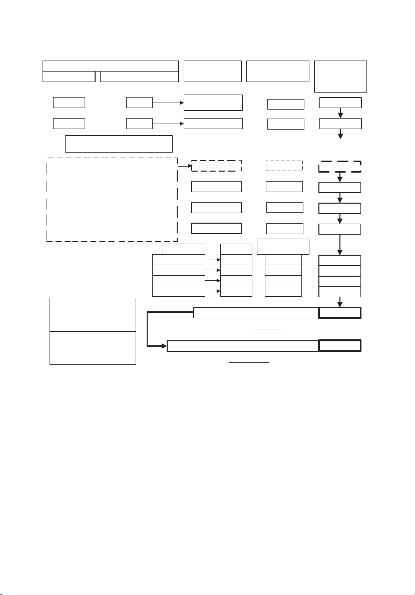
44- SP
A04669
CALCULADORA DE WATAJE PARA ARTEFACTOS DOMÉSTICOS
DISPOSITIVOS CON CARGAS (INDUCTIVAS) DE ARRANQUE ALTAS
WATAJE DE OPERACIÓN
500
400
¡¡
NO CONECTE EQUIPOS ELECTRÓNICOS
SENSIBLES A LAS SOBRECARGAS DE
VOLTAJE (TELEVISORES, COMPUTADORAS,
ETC.) DIRECTAMENTE AL GENERADOR.
CONÉCTELOS A UN PROTECTOR DE
SOBRECARGAS DE VOLTAJE APROBADO
POR UL QUE A SU VEZ ESTÉ CONECTADO
AL GENERADOR.
AVISO: NO USAR UN PROTECTOR DE
SOBRECARGAS APROBADO POR UL DAÑARÁ
ESOS EQUIPOS Y SUS GARANTÍAS
SE INVALIDARÁN.
POR (X) FACTOR DE ARRANQUE
x
x
2
2
PRECAUCIÓN!!
ILUMINACIÓN
FOCO DE 60 WATS
FOCO DE 75 WATS
FOCO DE 100 WATS
FOCO DE 300 WATS
*PARA ARTEFACTOS NO
INDICADOS, REFERIRSE
A LAS INSTRUCCIONES
PARA CALCULAR
**WATAJE PROMEDIO. EL
WATAJE REAL DE CADA
ARTEFACTO PUEDE SER
MAYOR O MENOR
WATAJE
TÍPICO**
=
=
=
=
=
=
POR CANTIDAD
DE FOCOS
x
x
x
x
1000
800
300
800
800
42
=
=
=
=
=
=
=
=
=
=
TOTAL
¡
PRECAUCIÓN!
ARTEFACTO O
DISPOSITIVO
HERRAMIENTA DE
MANO INALÁMBRICA
LICUADORA
TELEVISIÓN
MICROONDAS
SECADOR DE CABELLO
VENTILADOR PEQUEÑO
WATS
60
75
100
300
DEMANDA ELÉCTRICA TOTAL
ESTA DEMANDA DEBE SER MENOR A LA CAPACIDAD DEL GENERADOR
CAPACIDAD DE SALIDA DEL GENERADOR
ESTE TOTAL DEBE SER MAYOR QUE LA DEMANDA DE WATAJE DE LA CASA
Page 45

45- SP
A04669
GUÍA DE DIAGNOSTICO Y SOLUCION DE PROBLEMAS
PROBLEMA
CAUSA
CORRECCIÓN
El motor no
arranca
No produce
electricidad
Aberturas
continuadas
del interruptor
de circuito
El generador
recalienta
1. Poco combustible o
aceite.
2. El interruptor del motor
está en posición apagado
(off).
3. Bujía defectuosa.
4. Estrangulador (choke) en
posición equivocada.
5. Palanquita de la válvula
de control en posición
cerrada.
6. El generador está con
artefactos conectados al
momento de arrancar.
7. Cable de la bujía suelto.
8. Línea de combustible
obstruida.
9. Falla en el sistema de
encendido.
1. Tomacorriente
defectuoso.
2. Interruptor de circuito
abierto (ha saltado).
3. Capacitador defectuoso.
4. Cordón eléctrico
defectuoso.
1. Sobredemanda.
2. Cordones o equipo
defectuoso
1. Exceso de demanda para
el generador.
2. Ventilación insuficiente.
1. Aumente combustible o aceite.
2. Coloque el interruptor en la
posición de encendido (on).
3. Cambe la bujía.
4. Regule la estrangulación
(choke) según se necesite.
5. Abra la válvula de combustible
con la palanquita.
6. Desconecte los artefactos que
crean demanda a la unida.
7. Conecte bien el alambre de la
bujía.
8. Limpie la línea de combustible
y el filtro.
9. Consulte a un servicentro.
1. Haga que un servicentro lo
reemplace.
2. Oprima y reactive.
3. Haga que un servicentro
cambie el capacitador.
4. Repare o cambie el cordón.
1. Reduzca la demanda.
2. Revise si los cordones están
dañados, pelados o trenzados
en el equipo. Reemplácelos.
1. Reduzca la demanda.
2. Traslade el generador a un
lugar con suficiente aire fresco.
Page 46

46- SP
A04669
REPUESTOS DISPONIBLES
No. de Pieza Descripción
Z-A05449 Tapa de combustible
Z-A05451 Filtro de aire
Z-A05453 Válvula de corte de combustible
Z-A05454 Filtro de combustible
Z-A05458 Conjunto del panel de control
Z-A05459 Conjunto de generador
Z-A05460 Conjunto de motor
Z-A05455 Tapa de la toma de aceite
Z-A05457 Resistencia de la bujía
Z-A05456 Capacitador
Page 47

47- SP
A04669
GARANTÍA LIMITADA
DeVilbiss Air Power Company garantiza al comprador original de esta unidad que la usa con fines no comerciales
(personales, residenciales o domésticos) contra defectos de materiales o de fabricación por un año a partir de la
fecha de su compra. Todas las unidades cubiertas bajo esta garantía utilizadas comercialmente (p. ej.: para
producir ingresos) están cubiertas contra defectos de materiales y de fabricación por 90 días a partir de su fecha
original de compra. Los equipos cubiertos por esta garantía incluyen compresores de aire, herramientas
neumáticas, repuestos, lavadoras de presión y generadores.
DeVilbiss Air Power Company, a su criterio, reparará o reemplazará, las unidades o componentes que hubiesen
fallado dentro del periodo de la garantía. El servicio se programará de acuerdo al flujo y horario normal de trabajo
del servicentro autorizado y a la disponibilidad de piezas de repuesto. Las decisiones de DeVilbiss Air Power
Company relacionadas con esta garantía limitada son definitivas.
Esta garantía le otorga derechos legales específicos y usted también podría tener otros derechos que varían de un
estado a otro.
RESPONSABILIDAD DEL COMPRADOR ORIGINAL (Usuario Inicial):
• Para procesar un reclamo bajo esta garantía, NO devuelva la unidad al lugar donde se compró. La unidad debe
evaluarse en un servicentro de garantías autorizado. Para ubicar el servicentro más cercano, llame
al 1-800-888-2468 durante las 24 horas del día, los 7 días de la semana, o visite nuestro sitio web en
www.devap.com.
• Conserve el recibo del pago original como comprobante de su compra para hacer reclamos cubiertos por
la garantía.
• Tener cuidado razonable al operar la unidad y darle mantenimiento según se describe en el Manual del
Propietario.
• Remita o entregue la unidad al servicentro de garantías autorizado más cercano. El costo de los fletes, si
alguno, debe pagarlo el comprador.
• Los compresores de aire con tanques de 60 y 80 galones serán inspeccionados en el lugar de la
instalación. Comuníquese con el servicentro de garantías autorizado más cercano que dé servicio a
domicilio para hacer los arreglos.
• Si el comprador no estuviese satisfecho con el servicio recibido del servicentro de Garantías Autorizado
por, el comprador debe comunicarse con DeVilbiss Air Power Company.
ESTA GARANTÍA NO CUBRE:
• Mercadería vendida como reacondicionada, equipos usados para alquiler ni modelos de exhibición.
• Mercadería que se ha dañado o vuelto inoperante debido a su desgaste normal, uso inadecuado*, frío,
calor, lluvia, humedad excesiva, daños de congelamiento, uso con productos químicos inadecuados,
negligencia, accidente, operación sin seguir las instrucciones suministradas en el Manual del Propietario,
uso de accesorios o aditamentos no recomendados ni autorizados por DeVilbiss Air Power Company o
reparaciones o alteraciones no autorizadas.
* Un compresor de aire que bombea aire por más del ciclo recomendado dentro de una hora podría
considerarse que se usa indebidamente
• Los costos de reparación y transporte de mercadería determinada como no defectuosa.
• Los costos de ensamblaje, el aceite requerido, ajustes u otro gasto de instalación o puesta en operación.
• Piezas sujetas a desgaste que se proveen con la unidad y que se espera que se vuelvan inoperantes o
inusables después de un tiempo razonable, incluyendo, pero no limitándose a discos lijadores, hojas de
sierra y de cizalla, piedras de esmeril, resortes, cinceles, boquillas, anillos "O", boquillas de aire, arandelas y
accesorios similares.
• Mercadería vendida por DeVilbiss Air Power Company que ha sido fabricada por terceros e identificada
como tal; p. ej.: motores de gasolina. La garantía que se aplica, si alguna, es la de su fabricante.
• LAS PÉRDIDAS, DAÑOS O PERJUICIOS INCIDENTALES, INDIRECTOS O CONSECUENCIALES QUE
PUDIESEN RESULTAR DE CUALQUIER DEFECTO, FALLA O MAL FUNCIONAMIENTO DE LA UNIDAD NO
ESTÁN CUBIERTOS POR ESTA GARANTÍA. Algunos estados no permiten la exclusión o limitación
de los daños incidentales o consecuenciales, por lo que estas limitaciones o exclusiones podrían no
aplicarse a usted.
• LAS GARANTÍAS IMPLÍCITAS, INCLUIDAS AQUELLAS DE COMERCIALIZACIÓN O IDONEIDAD PARA UN
PROPÓSITO PARTICULAR, ESTÁN LIMITADAS A UN AÑO A PARTIR DE LA FECHA ORIGINAL DE
COMPRA. Algunos estados no permiten limitaciones a la duración de las garantías implícitas, por lo que
estas limitaciones podrían no aplicarse a usted.
213 Industrial Drive • Jackson, TN 38301-9615
Teléfono: 1-800-888-2468
FAX: 1-800-888-9036
Page 48

48- SP
A04669
NOTAS
Page 49

49- FR
A04669
Lisez le Guide de l’utilisateur. Ne tentez pas d’utiliser cet
appareil avant d’avoir lu les directives sur la sécurité,
l’assemblage, l’utilisation et l’entretien de ce Guide de l’utilisateur.
Ce produit est équipé d’un silencieux à pare-étincelles. Selon
la section 130050 de la loi de la Californie, et les sections
4442 et 4443 du Code sur les ressources publiques de la Californie, ce produit ne peut
pas être utilisé en Californie, à moins que le moteur ne soit équipé d’un pare-étincelles,
tel que décrit dans la section 4442, et à moins que l’appareil ne soit maintenu en bon
état de fonctionnement. Des pare-étincelles sont également requis sur certaines terres
forestières des États-Unis et peuvent être exigés légalement sous certains autres lois et
arrêtés.
Les gaz d’échappement du moteur contiennent des produits
chimiques qui, dans certaines quantités, peuvent causer le
cancer, les anomalies congénitales ou d’autres maux de reproduction.
RENSEIGNEMENTS SUR LA SÉCURITÉ DU CONSOMMATEUR
RENSEIGNEMENTS GÉNÉRAUX ET SUR LE SERVICE APRÈS-VENTE
NE PAS RETOURNER CE PRODUIT AU VENDEUR ! POUR CONNAÎTRE LES OPTIONS
CONCERNANT LE SERVICE, COMPOSEZ LE 1-800-888-2468
• Veuillez lire et suivre les instructions de ce guide afin d’assurer une utilisation et un entretien
appropriés de l’appareil.
• Veuillez prendre un moment maintenant pour enregistrer votre génératrice en ligne à
www.devap.com.
• Si vous avez des problèmes ou si vous avez besoin d'aide, veuillez communiquer avec nous
au numéro sans frais 1-800-888-2468, du lundi au samedi entre 8 h et 18 h HNC.
• S'il faut faire réparer votre appareil ou si vous avez besoin d'une pièce de rechange, un
grand nombre de centres de service sous garantie autorisés existent à des endroits
pratiques et sont en mesure d'offrir des services d'entretien sous garantie et hors de la
garantie.
• Pour connaître l'emplacement du centre de service sous garantie autorisé le plus près de
chez vous, composez le 1-800-888-2468, 24 heures par jour, 7 jours par semaine ou visitez
notre site Web à devap.com.
• Veuillez conserver le reçu de caisse comme preuve d'achat aux fins de la garantie.
• Lisez attentivement tous les avertissements de sécurité.
• Ne tentez pas d’utiliser cet appareil avant d’avoir lu attentivement les directives sur la
sécurité, l’utilisation et l’entretien de ce Guide de l’utilisateur.
Page 50

50- FR
A04669
RISQUES D'ÉLECTROCUTION ET D’INCENDIE
Tenter de brancher
la génératrice
directement au
système électrique
d’un édifice
quelconque.
L’acheminement d’une tension
électrique à travers un système
électrique, vers les lignes de distribution électrique extérieures, risque de
mettre en danger les techniciens en
train d’essayer de rétablir
l’alimentation électrique.
Ne jamais acheminer une tension électrique
vers les lignes de distribution électrique
extérieures d’un édifice.
Une utilisation ou un entretien non appropriés de ce produit peut causer
des blessures graves et des dommages à la propriété. Lisez
attentivement tous les avertissements et les directives d'utilisation avant d'utiliser cet
appareil.
RISQUE
PRÉVENTION
MESURES DE SÉCURITÉ / DÉFINITIONS
Ce guide contient des renseignements importants que vous deviez bien saisir. Cette information
porte sur VOTRE SÉCURITÉ et sur LA PRÉVENTION DE PROBLÈMES D’ÉQUIPEMENT. Afin de
vous aider à identifier cette information, nous avons utilisé les symboles ci-dessous. Veuillez lire
attentivement ce guide en portant une attention particulière à ces sections.
Indique un danger imminent qui, s'il n'est pas évité, causera de graves
blessures ou la mort.
Indique la possibilité d’un danger qui, s’il n’est pas évité, pourrait
causer de graves blessures ou la mort
.
Indique la possibilité d’un danger qui, s’il n’est pas évité,
peut causer des
dommages mineures ou moyennes.
Sans le symbole d’alerte.
Indique la possibilité d'un danger qui, s'il n'est pas
évité,
peut causer des
dommages à la propriété.
MESURES DE SÉCURITÉ IMPORTANTES
DANGER
Fonctionnement de
la génératrice en
présence de pluie,
d’humidité, de gel
ou d’inondation.
L’eau est un excellent conducteur
d’électricité ! L’eau qui entre en
contact avec des composantes
chargées d’électricité peut
transmettre l’électricité au châssis et
aux autres surfaces, entraînant des
chocs électriques aux personnes
touchant ces surfaces.
Utiliser la génératrice dans un endroit
propre, sec et bien aéré. S’assurer d’avoir
les mains sèches avant de toucher à
l’appareil.
Page 51

51- FR
A04669
Utilisation de
l’appareil lorsqu’il
est endommagé ou
lorsque les
dispositifs de
sécurité ou les
panneaux sont
retirés.
L’enlèvement de dispositifs de
sécurité peut exposer les
composantes chargées
électriquement et entraîner une
électrocution.
Ne pas utiliser la génératrice lorsque les
dispositifs de sécurité sont retirés.
Connexion
inappropriée des
composantes à la
génératrice.
Le dépassement de la capacité de
charge de la génératrice par le
branchement d’une quantité
excessive de composantes ou de
composantes de charges très élevées
peut provoquer une surchauffe des
câbles ou des composantes reliées et
provoquer un incendie ou des chocs
électriques.
La tentative d’utiliser l’appareil
lorsqu’il a été endommagé ou
lorsqu’il ne fonctionne pas
normalement peut entraîner un
incendie ou une électrocution.
Veuillez consulter le tableau des valeurs
nominales de charges et les directives
dans la section intitulée « Calcul de la
puissance en watts ». S’assurer que le
total des charges électriques pour tous
les branchements n’excède pas la charge
nominale de la génératrice.
Ne pas utiliser la génératrice lorsqu’elle
présente des défectuosités mécaniques ou
électriques. Faire réparer la génératrice
par un centre de service après-vente
autorisé.
Utilisation de
rallonges
électriques
endommagées, de
calibre insuffisant
ou sans mise à la
terre.
L’utilisation de rallonges électriques
sans mise à la terre peut empêcher
le fonctionnement des coupe-circuit
et entraîner des chocs électriques.
Toujours se servir d’un cordon
d’alimentation muni d’un fil de mise à la
terre et d’une fiche de mise à la terre
appropriée. NE JAMAIS utiliser une fiche
sans mise à la terre.
Utiliser une rallonge électrique de
calibre (de fils) approprié selon votre
application. Consulter la section intitulée
"Assemblage".
Le contact à une rallonge électrique
usée ou endommagée peut entraîner
une électrocution.
L’utilisation de rallonges électriques
de calibre insuffisant peut provoquer
une surchauffe des câbles ou des
composantes reliées et causer un
incendie.
Inspecter la rallonge électrique avant
l’utilisation et la remplacer par une rallonge
neuve au besoin.
Placer la
génératrice sur ou
contre une surface
conductrice telle
qu’une passerelle
d’acier ou un toit
en métal.
Placer la génératrice sur une surface à
faible conductivité telle qu’une dalle en
béton.
Des fuites accidentelles de courant
électrique peuvent charger les
surfaces conductrices en contact
avec la génératrice
RISQUES D'ÉLECTROCUTION ET D’INCENDIE
(suite)
TOUJOURS utiliser la génératrice à une
distance minimum de 1,8 m (6 pi) de toute
surface conductrice.
RISQUE
PRÉVENTION
DANGER
Page 52

52- FR
A04669
RISQUES D’INCENDIE
Entreposage
inapproprié du
carburant.
L’entreposage inapproprié du
carburant peut entraîner une
inflammation accidentelle. Du
carburant conservé dans des zones
non sécuritaires pourrait être à la
portée des enfants ou d’autres
personnes non qualifiées.
Entreposer l’essence dans des contenants
approuvés par l'OSHA et conçus pour de
l’essence. Entreposer les contenants dans
des endroits sécuritaires afin d’en
empêcher l’utilisation par d’autres
personnes.
Remplissage du
réservoir à
carburant pendant
que la génératrice
est en marche.
L’essence ou les vapeurs d’essence
peuvent s’enflammer au contact de
composantes chaudes telles que le
silencieux, les gaz d’échappement du
moteur ou une étincelle électrique.
Les cigarettes, les étincelles, les
incendies ou d’autres objets
chauds peuvent entraîner
l’inflammation de l’essence ou des
vapeurs d’essence
Arrêter le moteur et le laisser refroidir avant
d’ajouter de l’essence dans le réservoir.
S’assurer de la disponibilité d’un extincteur
certifié pour les incendies impliquant de
l’essence ou du carburant dans la zone de
remplissage.
Remplir le réservoir dans une zone bien
aérée. S’assurer qu’aucune source
d’inflammation n’est à proximité de la
génératrice.
Utiliser la génératrice dans un endroit
propre, sec et bien aéré, et s’assurer qu’elle
se trouve à au moins 1,2 m (4 pi) de tout
édifice, objet ou mur. NE PAS UTILISER
L’APPAREIL À L’INTÉRIEUR OU DANS UN
ENDROIT CLOS.
Des matériaux placés contre ou à
proximité de la génératrice ou
l’utilisation de la génératrice dans
des zones où la température
ambiante excède 40° C (104° F)
(tels que les salles d'entreposage ou
les garages) peuvent entraver
l’efficacité du système d’aération et
provoquer ainsi une surchauffe et
une inflammation des matériaux ou
des édifices.
Étincelles, incendie,
objets chauds.
Aération
inappropriée
pour la
génératrice.
Modification des
réglages de
vitesse du moteur
du fabricant.
La vitesse du moteur a été réglée à
l’usine par le fabricant afin d’en
assurer un fonctionnement
sécuritaire. La modification des
réglages de la vitesse du moteur peut
provoquer une surchauffe des
composantes reliées et entraîner un
incendie.
Les déversements de carburant et
les vapeurs s’en échappant
peuvent s’enflammer au contact de
surfaces chaudes ou d’étincelles.
Ne jamais tenter d’augmenter la vitesse
du moteur en vue d’obtenir un meilleur
rendement car si vous le faites, la tension
et la fréquence de sortie seraient hors
norme et présenteraient des risques aux
composantes reliées et à l’utilisateur.
Prendre toutes les précautions d’usage lors
du remplissage du réservoir afin d’éviter tout
déversement de carburant. S’assurer que le
bouchon du réservoir est correctement
fermé et vérifier si de l’essence fuit du
moteur avant de mettre le moteur en
marche. Déplacer la génératrice de la zone
de remplissage ou de tout déversement
avant de mettre le moteur en marche.
Laisser assez d’espace pour l’expansion du
carburant. Garder le niveau de carburant à
un maximum de 6 mm (1/4 po) sous la partie
supérieure du réservoir à carburant. Ne
jamais remplir le réservoir lorsque le moteur
est en marche.
Remplissage
excessif du réservoir
à carburant déversement de
carburant.
RISQUE
PRÉVENTION
DANGER
Page 53

53- FR
A04669
RISQUES D’UNE UTILISATION
DANGEREUSE
Utilisation de la
génératrice avec
négligence.
Toutes les sources d’énergie
représentent des risques potentiels
de blessures. Utiliser ou entretenir la
génératrice avec négligence peut
entraîner des blessures graves ou la
mort de l’opérateur ou d’autres
personnes.
• Consulter à nouveau ce manuel afin de
bien comprendre les directives
d’utilisation et les avertissements.
• Se familiariser avec le fonctionnement et
les commandes de l’appareil. Il est
important de connaître la façon de
mettre rapidement l’appareil hors
fonction.
• S’assurer de la disponibilité d’un
extincteur certifié pour les incendies
impliquant de l’essence ou du carburant
dans la zone d’utilisation.
• Garder les enfants et les autres
personnes éloignés de la génératrice en
tout temps.
RISQUES AUX VOIES RESPIRATOIRES
ET RISQUES D’INHALATION
L’inhalation de gaz d’échappement
peut entraîner des blessures graves
ou la mort.
Utiliser la génératrice dans un endroit
propre, sec et bien aéré. Ne jamais utiliser
l'appareil dans des endroits clos tels que
les garages, sous-sols et hangars
d’entreposage ni dans des endroits
occupés par des êtres humains ou des
animaux. Garder les enfants, les animaux
domestiques et autres, éloignés de
l’appareil en marche.
Les moteurs à
essence
produisent des
émanations de
monoxyde de
carbone toxiques.
RISQUES DE BLESSURES ET DE
DOMMAGES À LA PROPRIÉTÉ PENDANT
LE TRANSPORT DE LA GÉNÉRATRICE
Incendie,
inhalation et
dommages aux
surfaces du
véhicule.
Des fuites ou des déversements de
carburant ou d’huile peuvent se
produire et entraîner des risques
d’incendie ou des problèmes aux
voies respiratoires, des blessures
graves ou la mort. Des fuites de
carburant ou d’huile endommagent
les tapis, la peinture et toute autre
surface des véhicules ou des
remorques.
Si la génératrice est munie d’une soupape
d’arrêt, tourner la soupape à la position
fermée avant le transport de façon à éviter
tout risque de fuite. Si la génératrice n’est
pas munie d’une soupape d’arrêt, vidanger
le carburant du réservoir avant le transport.
Ne transporter le carburant que dans des
contenants approuvés par l’OSHA. Pour le
transport, toujours placer la génératrice sur
un tapis de protection pour éviter
l’endommagement du véhicule par des
fuites. Retirer la génératrice du véhicule
immédiatement à l’arrivée.
RISQUE
PRÉVENTION
DANGER
RISQUE
PRÉVENTION
DANGER
RISQUE
PRÉVENTION
DANGER
Page 54
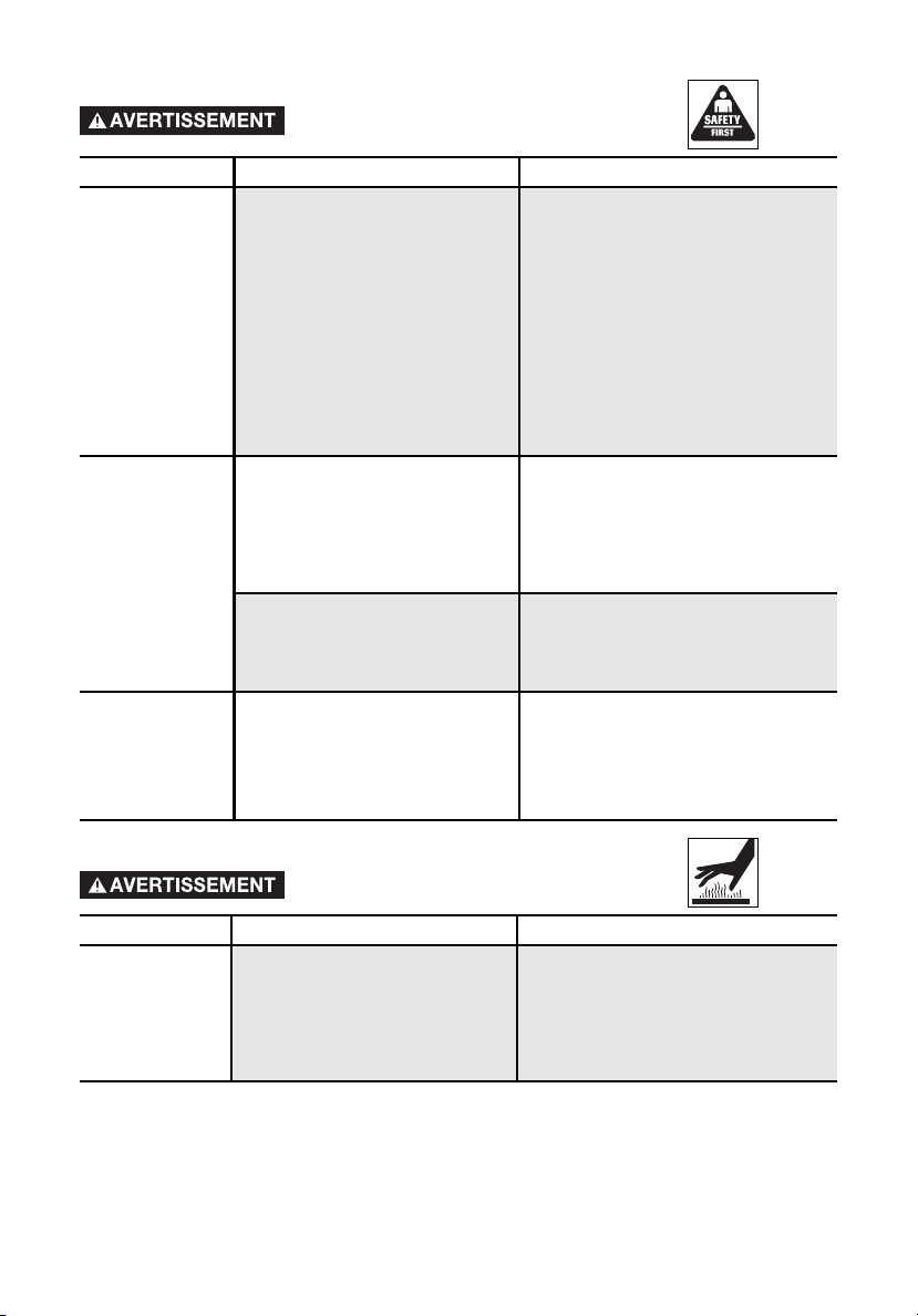
54- FR
A04669
RISQUES D’UNE UTILISATION
DANGEREUSE (suite)
Une suspension ou un soulèvement
non approprié risque d’endommager
la génératrice.
Toujours utiliser des câbles, des chaînes ou
des sangles capables d’accepter une
charge de 907 kg (2 000 lb) ou plus pour
soulever ou suspendre une génératrice.
Suspension ou
soulèvement non
approprié de
génératrices
équipées
d’anneaux de
levage
La génératrice peut tomber,
entraînant des blessures graves ou la
mort de l’opérateur ou d’autres
personnes.
Toujours suivre la procédure de connexion
appropriée indiquée dans ce guide en
attachant les câbles, les chaînes ou les
sangles pour soulever ou suspendre une
génératrice équipée d’anneaux de levage.
Fonctionnement
d’une génératrice
lorsqu’elle est
suspendue
La génératrice sera endommagée et
ne fonctionnera pas de façon
appropriée ; de plus elle peut
entraîner des blessures graves ou la
mort de l’opérateur ou d’autres
personnes.
Ne jamais faire fonctionner la génératrice
lorsqu’elle est suspendue ou lorsqu’elle
n’est pas à niveau. Toujours utiliser la
génératrice sur une surface plate et à
niveau.
Le contact avec les surfaces
chaudes, telles que les composantes
d’échappement du moteur, peut
entraîner des brûlures graves.
Lors du fonctionnement, ne toucher que
les surfaces de commande de la
génératrice. En tout temps, garder les
enfants éloignés de la génératrice. Ils ne
sont peut-être pas capables de détecter
les risques inhérents à ce produit.
RISQUE
PRÉVENTION
DANGER
RISQUE
PRÉVENTION
DANGER
Utiliser toujours un protecteur de surtension
sensible à la tension et homologué U.L.
pour brancher les appareils sensibles aux
variations de tension (téléviseur, ordinateur,
chaîne stéréophonique, etc.). Le
manquement à utiliser un protecteur de
surtension homologué U.L. annule la
garantie de la génératrice.
Remarque : Une lisière à prises multiples
n’est pas un protecteur de surtension ;
s’assurer d’utiliser un protecteur de
surtension homologué U.L.
Toutes les génératrices domestiques
à essence produisent des variations
de tension pouvant endommager les
appareils sensibles aux variations de
tension ou provoquer un incendie.
Fonctionnement
des appareils
électroménagers
sensibles aux
variations de
tension sans
protecteur de
surtension.
Contact avec les
composantes
chaudes du moteur
et de la
génératrice.
RISQUES RELIÉS AUX SURFACES
CHAUDES
Page 55

55- FR
A04669
SPÉCIFICATIONS
MODÈLE GM1000
PUISSANCE 2,4 HP
PUISSANCE NOMINALE/DE POINTE 1 000/1 250 WATTS
TENSION 120 V
INTENSITÉ 8,3 A
PHASE MONOPHASÉE
HERTZ 60 Hz
VITESSE DU MOTEUR 3 600 TR/MIN
TEMP. AMBIANTE MAX. 40° C (104° F)
CAPACITÉ DE CARBURANT 4,5 LITRES (1,2 GALLON)
TEMPS DE FONCTIONNEMENT À 50 %/100 % 8/6 HEURES
RISQUES RELIÉS AUX PIÈCES
MOBILES
RISQUES LORS DU LEVAGE
Cette génératrice est lourde et vous
aurez peut-être besoin d'aide pour
le lever.
Le levage d'un objet lourd peut
entraîner des blessures graves.
Levage d'un
objet lourd.
Une génératrice portative peut
tomber d'une table, d'un établi ou
d'un toit, ce qui peut endommager
la génératrice ou causer des
blessures graves ou la mort.
Toujours placer la génératrice dans
une position stable et sécuritaire
pour empêcher tout mouvement
accidentel de l'appareil. Ne jamais
utiliser la génératrice sur un toit ou
un autre endroit élevé.
DANGER
RISQUE
PRÉVENTION
RISQUES DE TOMBER
Une génératrice
portative peut
tomber d'une
position élevée,
ce qui peut
endommager
l'équipement ou
causer des
blessures
graves.
Ne jamais faire fonctionner la génératrice
lorsque les dispositifs de sécurité ou les
couvercles ne sont pas en place. Éviter
de porter des vêtements amples ou des
bijoux qui risquent d’entrer en contact
avec les pièces mobiles.
Pendant le fonctionnement de la
génératrice, certaines de ses pièces
tournent à des vitesses élevées. Ces
pièces sont recouvertes de dispositifs
de sécurité pour éviter toute blessure.
Le contact avec
des pièces
mobiles peut
entraîner des
blessures graves.
DANGER
RISQUE
PRÉVENTION
DANGER
RISQUE
PRÉVENTION
Page 56
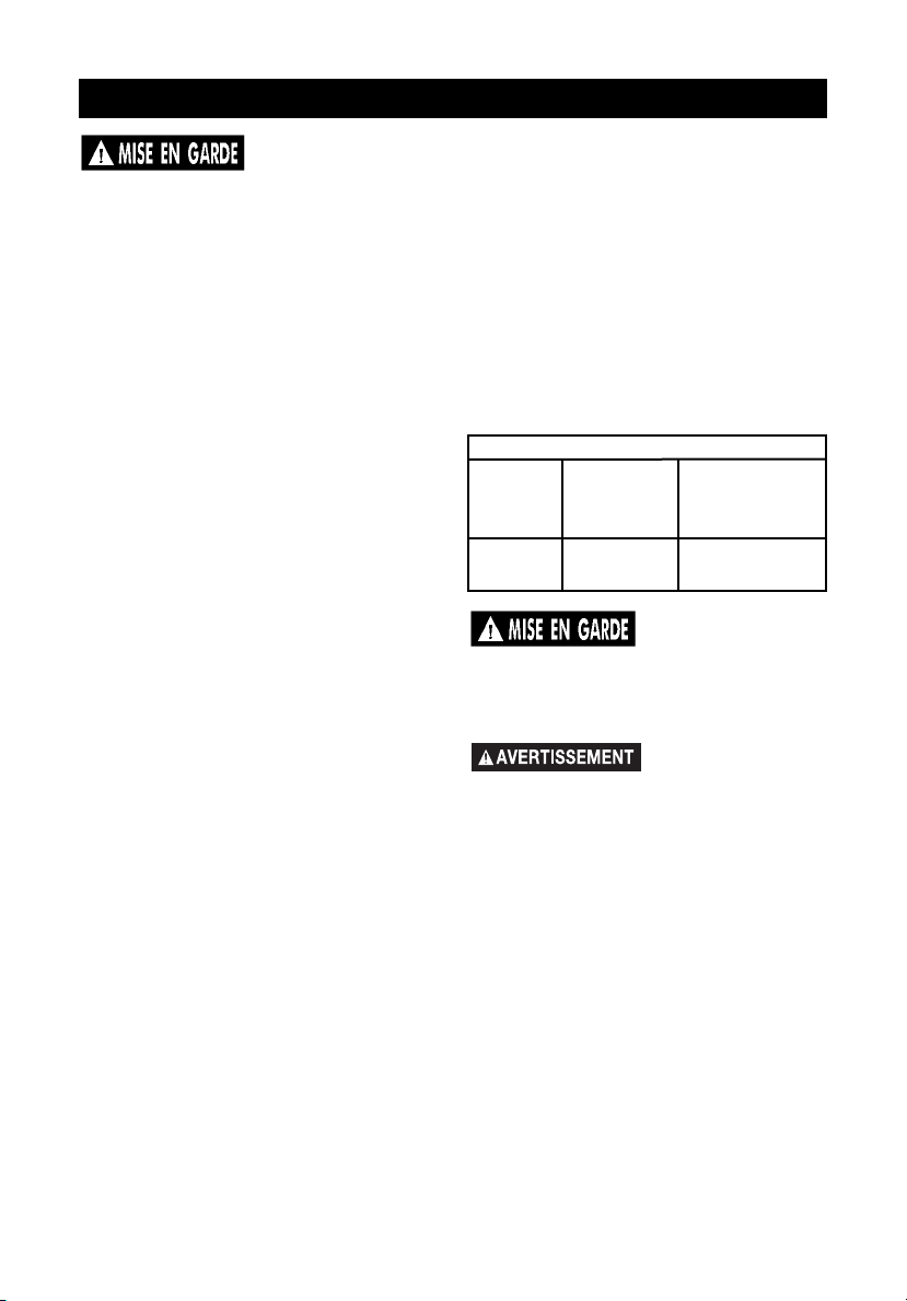
56- FR
A04669
ASSEMBLAGE
Tableau des calibres de fil pour rallonges
Intensité
Longueur
de la
rallonge
Calibre
de fil
Jusqu'à 10
ampères
Calibre 14
0 à 30 m
(0 à 100 pi)
REMARQUE : La mention « gauche »
ou « droite » signifie l’emplacement
d’une pièce lorsque l’utilisateur est
situé face au panneau des prises
électriques.
RETRAIT DE LA GÉNÉRATRICE
DE SON EMBALLAGE
• Ouvrir la boîte par le dessus.
• Chercher et retirer la trousse de
poignée.
• À l'aide des vis et du tournevis
fournis, poser la poignée sur la partie
supérieure de la génératrice.
Conserver le tournevis et la clé de
bougie d'allumage pour l'usage futur.
• Soulever la génératrice de la boîte
avec soin.
MISE À LA TERRE DE LA
GÉNÉRATRICE
Une vis de mise à la terre est fournie sur
la génératrice. Elle doit être utilisée si les
normes d’électricité locales l’exigent. Se
référer à l’article 250 du Code national
de l’électricité (National Electrical Code)
pour de plus amples renseignements
sur la mise à la terre. Votre compagnie
de service électrique locale ou un
électricien qualifié devrait être dans la
mesure de vous offrir ces
renseignements.
Lire ce Guide de
l’utilisateur. Ne pas
faire fonctionner l’appareil avant
d’avoir lu les parties traitant de la
sécurité, de l’utilisation et de
l’entretien de ce Guide de l’utilisateur.
RALLONGES
Afin de réduire le risque de chocs
électriques en utilisant un appareil ou un
outil considérablement éloigné de la
génératrice, il FAUT se servir d’une
rallonge à trois fils, dotée d’une fiche de
mise à la terre à trois broches, et d’une
prise à trois fentes qui s’adapte à la fiche
de l’outil. Il faut également utiliser une
rallonge de calibre approprié. Le tableau
suivant sert à déterminer le calibre de fil
minimum requis.
Si une rallonge est
chaude, elle est
trop chargée. Réparer ou remplacer
immédiatement toute rallonge
endommagée.
NE PAS brancher
cette génératrice
à la source d'alimentation électrique
principale entrant dans une maison.
Page 57

57- FR
A04669
UTILISATION
1. Interrupteur marche/arrêt « On/Off » du
moteur - Met le système d'allumage en
fonction et hors fonction.
2. Lampe témoin - Indique que la
génératrice produit une tension électrique.
3. Sortie de 12 V CC - Fournit une tension
électrique aux appareils de 12 V CC.
REMARQUE : Cette sortie ne doit être
utilisée que pour alimenter les appareils
de 12 V CC. Ne pas utiliser cette sortie
pour charger des batteries.
4. Vis de mise à la terre - Cette vis
constitue le point de fixation d'un fil de
mise à la terre à un dispositif de mise à la
terre externe.
5. Prise de courant - La prise double de
120 V fournit la tension aux appareils de
120 V.
6. Bouchon du réservoir de carburant Remplir le réservoir à carburant avec de
l'essence sans plomb, propre et fraîche,
ayant un indice d'octane de 87 ou plus.
7. Disjoncteurs - Chaque prise de courant
est munie d'un disjoncteur qui protège la
génératrice contre les surcharges. Si le
disjoncteur est déclenché, débrancher
toutes les charges électriques de la
génératrice. Attendre jusqu'à ce que le
disjoncteur soit refroidi. Appuyer sur le
bouton du disjoncteur pour le réinitialiser.
8. Trou de remplissage d'huile - Remplir le
carter avec de l'huile SAE 10W-30.
9. Échappement du silencieux
10. Levier de la soupape de carburant -
Ouvre et ferme la connexion entre le
réservoir à carburant et le carburateur.
11. Étrangleur - Ouvre et ferme la soupape
d'étrangleur dans le carburateur.
12. Lanceur à rappel
BIEN CONNAÎTRE VOTRE GÉNÉRATRICE
Lire ce Guide de l’utilisateur et les mesures de sécurité avant de faire fonctionner
votre génératrice. Consulter le guide des pièces fourni pour une illustration de votre
génératrice et pour vous familiariser avec l’emplacement des commandes et des
réglages. Conserver tous les guides à titre de référence future.
Échappement
du silencieux (9)
Étrangleur (11)
Levier de la
soupape de
carburant (10)
Trou de remplissage d'huile (8)
Sortie de 12
V CC (3)
Disjoncteur
CC (7)
Vis de mise à
la terre (4)
Lampe
témoin (2)
Interrupteur
marche/arrêt
« On/Off » du
moteur (1)
Prise de
courant (5)
Disjoncteurs
CA (7)
Bouchon du
réservoir de
carburant (6)
Lanceur à
rappel (12)
Page 58

58- FR
A04669
DÉMARRAGE DU MOTEUR
1. Ouvrir le levier de la soupape de
coupure de carburant.
2. Régler la commande d'étrangleur à la
position d'étranglement « CHOKE ».
REMARQUE : Aucun étranglement n’est
nécessaire pour un moteur chaud. S’assurer
que la commande d’étrangleur est en position
« RUN » pour démarrer un moteur chaud.
3. Régler l'interrupteur marche/arrêt
« ON/OFF » du moteur à la position
de marche « ON ».
CAPACITÉ DE LA GÉNÉRATRICE
IMPORTANT : Si la capacité nominale de la
génératrice est dépassée, cela risque de
causer des dommages importants à la
génératrice et aux dispositifs électriques
branchés. Consulter la section intitulée
« Calcul de la puissance en watts » pour
vous aider à déterminer quels appareils et
outils vous pouvez faire fonctionner avec la
capacité en watts de votre génératrice.
AVANT DE DÉMARRER LE MOTEUR
Cette génératrice a été
expédiée de l’usine sans
huile dans le carter. Le fait de faire fonctionner
l’appareil sans huile peut endommager le
moteur.
Vérifier le niveau d’huile
moteur avant chaque
démarrage. La mise en marche du moteur
lorsque le niveau d’huile est insuffisant, ou
lorsqu’il n’y pas d’huile du tout, risque
d’endommager le moteur.
Suivre les étapes suivantes avant de démarrer
la génératrice :
1. Vérifier le niveau d'huile
à moteur. Voir la
section « Entretien »
pour connaître la
procédure appropriée.
2. Vérifier le niveau de
carburant et remplir le
réservoir au besoin.
S’assurer que la génératrice est hors
fonction et qu’elle est bien refroidie. Utiliser
de l’essence ordinaire pure, propre et sans
plomb, ayant un indice d’octane d’au moins
87. Ne pas mélanger de l’huile avec
l’essence.
Ne jamais remplir le
réservoir à carburant
jusqu’au bout. Remplir le réservoir jusqu’à 12 mm
(1/2 po) sous la base du col de remplissage afin
de permettre l’expansion du carburant. Essuyer
tout carburant versé sur le moteur ou sur
l’équipement avant de démarrer le moteur.
Ne jamais remplir le
réservoir à carburant à
l’intérieur. Ne jamais remplir le réservoir à
carburant lorsque le moteur tourne ou lorsqu’il
est encore chaud. Ne pas fumer au moment de
remplir le réservoir.
Ne jamais faire tourner le
moteur à l’intérieur ou
dans un endroit fermé sans aération adéquate.
Les gaz d’échappement du moteur contiennent
du monoxyde de carbone, un gaz toxique, sans
odeur.
3. S’assurer que la génératrice est mise à la
terre, conformément aux exigences
locales.
4. Toutes les charges électriques DOIVENT
être débranchées.
Le régime du moteur a
été réglé à l’usine pour
assurer un fonctionnement sans danger. Toute
modification au régime du moteur risque
d’entraîner une surchauffe des appareils
branchés et pourrait causer un incendie. Ne
jamais tenter d’augmenter le régime du
moteur afin d’obtenir un meilleur rendement.
La tension de sortie et la fréquence seront
mises hors des normes par une telle
modification, ce qui pourrait être dangereux
pour les appareils branchés et pour
l’utilisateur.
Il FAUT absolument
débrancher toute
charge de la génératrice avant de la mettre en
marche afin d’éviter d’endommager de façon
permanente les appareils branchés.
ON
OFF
OFF
Page 59

59- FR
A04669
BRANCHEMENT DE CHARGES
ÉLECTRIQUES
1. Pour réchauffer le moteur après le
démarrage, le laisser tourner sans charge
électrique pendant cinq minutes.
IMPORTANT : Si la vitesse du moteur ou la
tension oscille avec une charge inférieure à
250 watts, régler la commande d'étrangleur à
4. Saisissez la poignée du démarreur et tirer
lentement la corde jusqu’à ce qu’on sente
une résistance. Laisser la corde retourner
lentement. Tirer ensuite rapidement la
corde sur toute la longueur du bras.
Laisser la corde retourner lentement.
Répéter au besoin.
5. Une fois le moteur en marche, déplacer
graduellement la commande d’étrangleur
vers la position « RUN ».
IMPORTANT : Lors d’un démarrage initial,
laisser la génératrice fonctionner sans charge
pendant cinq minutes afin de permettre au
moteur et à la génératrice de se stabiliser.
ARRÊT DU MOTEUR
1. Débrancher toutes les charges
électriques.
2. Réglerl’interrupteur « ON/OFF » à la
position d’arrêt « OFF ».
3. Fermer la soupape d’arrêt de
carburant.
la position de demi-étranglement.
Brancher les charges de la façon suivante
afin d’éviter d’endommager l’équipement :
2. Brancher les charges inductives en
premier; les charges inductives
comprennent les petits outils à main et
certains petits appareils ménagers.
Brancher en premier les articles
nécessitant la plus grande puissance en
watts. Voir la section intitulée « Calcul de
la puissance en watts ».
3. Brancher ensuite les lumières.
4. Les appareils sensibles à la tension
devraient être branchés à la génératrice en
dernier lieu. Brancher les appareils
sensibles à la tension, tels que les
téléviseurs, magnétoscopes, micro-ondes,
et téléphones sans fil, dans un protecteur
de surtension homologué UL et brancher
ensuite le protecteur de surtension dans la
génératrice.
Si l’équipement n’est
pas branché de la
manière décrite, l’équipement peut être
endommagé et la garantie de la génératrice
sera annulée.
Suivre le tableau de calcul de la puissance
en watts dans la section intitulée « Calcul
de la puissance en watts » de ce guide.
Toute surcharge de la génératrice provoque
des fluctuations de puissance ce qui risque
d’endommager l’équipement et les
appareils ménagers.
DeVilbiss Air Power Company sera tenu
responsable des dommages encourus sur
l’équipement du client seulement s’il est
déterminé que la génératrice est
défectueuse. Ceci sera déterminé
seulement par un représentant autorisé de
DeVilbiss Air Power Company et cette
décision sera finale. Avant qu’une décision
de responsabilité légale ne soit prise,
DeVilbiss Air Power Company se réserve le
droit d’inspecter les connexions électriques
sur les lieux d’utilisation du client et de
tester la génératrice afin de déterminer si
elle fonctionne de façon appropriée. Si le
client ne conserve pas l’équipement ou les
fils pour une inspection, toute demande de
réclamation de garantie faite par le client
sera annulée. DeVilbiss Air Power Company
ne sera pas tenu responsable des
dommages encourus sur l’équipement suite
aux surtensions ou à une utilisation ou
installation non appropriée de la
génératrice.
ON
OFF
Page 60

60- FR
A04669
Remarque 1 : Changer l’huile après les premières deux (2) heures de fonctionnement et à
toutes les 50 heures pour les changements subséquents. Changer l’huile plus régulièrement si
l’appareil est utilisé dans un environnement extrêmement poussiéreux ou sale.
Remarque 2 : Vérifier l’huile après 5 heures de fonctionnement.
Remarque 3 : Toutes les 100 heures d'utilisation ou une fois par an.
TABLEAU DES RESPONSABILITÉS DU CLIENT
ENTRETIEN
RECOMMANDATIONS
GÉNÉRALES
La garantie de la génératrice ne couvre
pas les pièces qui ont subi un dommage
causé par en emploi abusif ou une
négligence de la part de l’utilisateur. Pour
s’assurer de tirer pleinement avantage de
la garantie, l’utilisateur doit entretenir la
génératrice selon les directives contenues
dans ce guide.
ENTRETIEN DE LA GÉNÉRATRICE
Votre génératrice doit être propre et sèche
en
tout temps. La génératrice ne devrait pas
être utilisée ou entreposée dans un
environnement excessivement humide ou
poussiéreux, ni en présence de vapeurs
corrosives. Dans ces cas, nettoyer la
génératrice en l’essuyant avec un chiffon ou
une brosse à poils souples. Ne pas se servir
d’un tuyau d’arrosage ou d’un appareil de
lavage sous pression pour nettoyer la
génératrice. L’eau risque de s’infiltrer dans
les fentes d’aération et d’endommager le
rotor, le stator et les enroulements internes
de la tête de la génératrice.
MOTEUR
Vérification du niveau d'huile
1. Arrêter le moteur et placer l'appareil
sur une surface de niveau.
2. Retirer le bouchon de remplissage
d'huile/couvercle de jauge d'huile.
TACHE D’ENTRETIEN
Avant
chaque
utilisation
Toutes les 25
heures de
chaque
saison
Toutes les 50
heures de
chaque
saison
Toutes les 100
heures de
chaque
saison
Vérification de la bougie d’allumage
Préparer l’appareil pour l’entreposage s’il ne sera
pas utilisé pendant 30 jours ou plus.
Vérification du niveau d’huile
Changement de l’huile
Nettoyage de l’ensemble de filtre à air
Préparation de l’appareil pour
l’entreposage
Voir Remarque 2
X
Voir Remarque
1
X
X
Voir Remarque 3
Nettoyage de la cuvette de soupape
de carburant
X
Nettoyage du filtre à carburant
X
Nettoyage du filtre du réservoir à
carburant
X
Nettoyage du tamis du silencieux
X
Page 61

61- FR
A04669
3. Retirer le bouchon de remplissage
d'huile/jauge d'huile.
4. Placer un récipient approprié sous le
trou de vidange d'huile du châssis.
5. Retirer le bouchon de vidange d'huile
et laisser l'huile vidanger dans le
récipient.
REMARQUE : Veuillez éliminer l'huile à
moteur usée d'une manière appropriée
pour la protection de l'environnement.
Nous vous recommandons d'apporter
l'huile usée dans un récipient scellé à un
centre de recyclage local ou une stationservice locale. Ne pas le jeter dans les
ordures et ne pas le verser sur la terre
ou dans un égout.
6. Remettre en place le bouchon de
vidange d'huile.
7. Avec le moteur positionné sur une
surface de niveau, ajouter de l'huile
SAE 10W-30 jusqu'à ce que l'huile
atteigne le rebord du trou de
remplissage d'huile.
REMARQUE : Vous pouvez utiliser une
des autres viscosités d'huile spécifiées
dans le tableau du paragraphe
« Vérification du niveau d'huile ».
8. Remettre en place le bouchon de
remplissage d'huile/jauge d'huile et le
fermer solidement.
Changement de l'huile
Vidanger l'huile à moteur lorsque le
moteur est chaud. Si l'huile est chaude,
elle se vidange rapidement et
complètement.
1. Arrêter le moteur tel que décrit dans la
section « Utilisation ».
2. Retirer le panneau inférieur du côté du
tableau de commande de l'appareil.
Retirer le panneau inférieur
Bouchon de
remplissage
d'huile/jauge
d'huile
Bouchon de vidange d'huile
Trou de vidange d'huile
3. Retirer le bouchon de remplissage
d'huile/jauge d'huile et l'essuyer.
4. Insérer le bouchon de remplissage
d'huile/jauge d'huile sans le visser
dans le trou de remplissage. Vérifier
le niveau d'huile indiqué sur la jauge
d'huile.
5. Si le niveau d'huile est bas, ajouter
de l'huile SAE 10W-30 jusqu'à ce
que l'huile atteigne le rebord du trou
de remplissage.
REMARQUE : Les autres viscosités
spécifiées dans le tableau peuvent être
utilisées si la température moyenne de
votre région est dans les limites
recommandées.
Bouchon de remplissage
d'huile/jauge d'huile
Bouchon de remplissage
d'huile/jauge d'huile
Limite supérieure
Limite inférieure
Degré de viscosité SAE
**
*
5W-30, 10W-30 synthétique
-20 0 20 40 60 80 100
F
-30 -20 -10 0 10 20 30 40
C
GAMME DE TEMPÉRATURES ANTICIPÉES LORS DES
DÉMARRAGES AVANT LA PROCHAINE VIDANGE D'HUILE
32
Page 62

62- FR
A04669
Filtre à air
Un filtre à air sale peut restreindre le débit
d'air au carburateur et entraîner un
rendement médiocre du moteur.
Inspecter le filtre chaque fois que
l'appareil est utilisé. Nettoyer le filtre plus
souvent si l'appareil est utilisé dans un
environnement très poussiéreux.
AVIS : En utilisant l'appareil sans le filtre,
la saleté peut entrer dans le moteur, ce
qui risque de causer une usure rapide du
moteur. Ce genre de dommage n'est pas
couvert par la garantie.
Nettoyage
1. Retirer les quatre vis fixant les côtés
du panneau et les deux attaches avec
isolateurs fixant la partie inférieure du
panneau. Retirer avec soin le panneau.
Veuillez noter que le filtre à carburant
et le lanceur à rappel sont fixés à ce
panneau.
2. Retirer les vis fixant l'élément en
mousse.
3. Laver l'élément avec de l'eau et un
détergent liquide. Le laisser sécher
complètement à l'air.
Vis
Vis
Attaches avec isolateurs
4. Appliquer de l'huile à moteur propre
sur l'élément et le presser pour enlever
l'huile excessive. NE PAS tordre
l'élément.
5. Remettre l'élément en place et
l'attacher.
6. Poser le panneau et le fixer solidement.
Vis
Vis
Élément
en mousse
Cuvette de soupape de carburant
Nettoyage
1. Arrêter le moteur tel que décrit dans la
section « Utilisation ».
2. Régler le levier de la soupape de
carburant à la position d'arrêt « OFF ».
3. Retirer les quatre vis fixant les côtés
du panneau et les deux attaches avec
isolateurs fixant la partie inférieure du
panneau. Retirer avec soin le panneau.
Veuillez noter que le filtre à carburant
et le lanceur à rappel sont fixés à ce
panneau.
Vis
Vis
Attaches avec isolateurs
Page 63

63- FR
A04669
Tamis du silencieux
Nettoyage
1. Arrêter le moteur tel que décrit dans
la section
«
Utilisation ».
2. À l'extrémité de l'échappement de
l'appareil, retirer les quatre vis fixant
les côtés du panneau et les deux
attaches avec isolateurs fixant la
partie inférieure du panneau. Retirer
avec soin le panneau de l'appareil.
Veuillez noter que la matière
d'isolation est fixée à ce panneau.
Filtre du réservoir à carburant
Nettoyage
1. Arrêter le moteur tel que décrit dans
la section
«
Utilisation ».
2. Retirer le bouchon et ensuite le filtre
du réservoir à carburant.
3. Le nettoyer avec un solvant. Essuyer
tout excès et placer le filtre dans le
réservoir à carburant.
Filtre à carburant
REMARQUE : Nous vous recommandons
d'utiliser toute l'essence restante dans le
réservoir avant de remplacer ou de
nettoyer le filtre à carburant.
1. Arrêter le moteur tel que décrit dans la
section « Utilisation ».
2. Régler le levier de la soupape de
carburant à la position d'arrêt « OFF ».
3. Retirer le panneau du côté du lanceur à
rappel tel que décrit dans le paragraphe
« Cuvette de soupape de carburant ».
4. La conduite de carburant peut être
retirée du couvercle du filtre à carburant
en serrant le collier de la conduite et en
le glissant vers le haut sur la conduite.
5. Une fois que la conduite de carburant
est retirée, dévisser le chapeau du
couvercle du filtre à carburant.
REMARQUE : Faire attention de ne pas
perdre la rondelle en caoutchouc du
chapeau du couvercle du filtre à carburant.
Couvercle de
filtre à
carburant
4. Dévisser et retirer la cuvette de la
soupape de carburant.
5. Nettoyer et remettre en place la
cuvette de la soupape de carburant.
Bien serrer.
6. Poser le panneau et le fixer solidement.
Soupape de
carburant
Cuvette de la
soupape de
carburant
4. Remettre en place le bouchon du
réservoir à carburant.
Collier de
conduite
Chapeau
Conduite de
carburant
6. Retirer le filtre à carburant pour le
nettoyer ou remplacer.
7. Insérer le filtre neuf ou nettoyé dans le
couvercle.
8. Insérer la rondelle en caoutchouc dans
le chapeau du filtre à carburant et visser
le chapeau dans le corps du couvercle
du filtre à carburant.
9. Reconnecter la conduite de carburant.
10. Poser le panneau et le fixer solidement.
Page 64

64- FR
A04669
Remplacement de la bougie
d'allumage
Remplacer la bougie d'allumage après
toutes les 100 heures d'utilisation ou une
fois par an, selon la première éventualité.
Ceci assure que le moteur démarre plus
facilement et tourne plus doucement.
REMARQUE : Utiliser la clé pour bougie
d'allumage et le tournevis fournis pour
retirer la bougie d'allumage. La bougie
d'allumage se situe sous le panneau
supérieur, du côté opposé des
commandes.
REMARQUE :
Bougie d'allumage standard :
BPR4ES (NGK)
Écartement de la bougie d'allumage :
0,7 à 0,8 mm (0,028 à 0,031 po)
Vis
Vis
Attaches avec isolateurs
Tamis du
silencieux
Retirer
la vis et
l'écrou
3. Retirer le tamis du silencieux.
4. Nettoyer le tamis du silencieux à
l'aide d'une brosse métallique.
5. Remettre en place le tamis du
silencieux et le fixer solidement.
6. Poser le panneau et le fixer
solidement.
Résistance
0,76 mm (0,030 po)
Calibre à fils
Page 65

65- FR
A04669
Si la génératrice ne va pas être utilisée
pendant 30 jours ou plus, utiliser les
renseignements suivants comme guide
pour la préparer pour l’entreposage.
Ne jamais
entreposer la
génératrice lorsqu’il y a du carburant
dans le réservoir, à l’intérieur ou dans
un endroit fermé sans aération
adéquate où les vapeurs risquent
d’atteindre une flamme nue, une
étincelle ou une veilleuse, par
exemple sur un fourneau, une
chaudière, une sécheuse ou un autre
appareil ménager à gaz.
PRÉPARATION DU MOTEUR
1. Ajouter un agent de stabilisation de
carburant au réservoir afin de
minimiser la formation de dépôts de
gomme de carburant lors de
l’entreposage.
2. Faire tourner le moteur pendant au
moins 10 minutes après avoir ajouté
l’agent de stabilisation afin de lui
permettre d’entrer dans le système
d’alimentation.
3. Couper le moteur.
4. Débrancher le fil de la bougie
d’allumage et retirer la bougie.
5. Ajouter une cuillère à thé d’huile
dans l’orifice pour bougie
d’allumage.
6. Placer un chiffon sur l’orifice pour
bougie d’allumage et tirer sur la
corde à recul à quelques reprises
pour lubrifier la chambre de
combustion.
7. Remettre la bougie d’allumage mais
sans brancher le fil de la bougie.
ENTREPOSAGE
REMARQUE : Si aucun agent de
stabilisation n’est utilisé, vidanger toute
l’essence du réservoir et du carburateur
afin d’empêcher la formation de dépôts
de gomme sur ces pièces, ce qui
pourrait provoquer le mauvais
fonctionnement du moteur.
IMPORTANT : Si l'essence est enlevée
du réservoir, il faut y verser de l'huile
pour empêcher la formation de rouille
dans le réservoir.
1. Verser une tasse (250 ml) d'huile
SAE 10W-30 dans le réservoir à
carburant.
2. Demander à une autre personne de
vous aider à secouer et à rouler
l'appareil de manière à ce que l'huile
couvre toutes les parois du réservoir
à carburant.
3. Vidanger l'huile excessive.
GÉNÉRATRICE
• Nettoyer la génératrice tel
qu’indiqué dans la section intitulée
« Entretien ».
• S’assurer que les fentes d’aération
et les ouvertures de la génératrice
ne sont pas obstruées.
Page 66

66- FR
A04669
CALCUL DE LA PUISSANCE EN WATTS
IMPORTANT
DÉTERMINATION DES EXIGENCES DE PUISSANCE EN WATTS
Avant d’utiliser cette génératrice, noter tous les appareils et les outils qui seront utilisés
simultanément. Déterminer ensuite les exigences de puissance de service et d’amorçage en
watts en suivant l’exemple ci-dessous ou consulter le tableau de calcul des puissances en
watts.
1. Calculer d’abord le total de la puissance de service en watts de tous les appareils et
outils qui seront utilisés simultanément.
Exemple 1 : Puissance de service Puissance d’amorçage
Lampes = 100 watts 0
Téléviseur = 300 watts 0
TOTAL = 400 watts 0
2. Calculer ensuite le total de la puissance d’amorçage en watts de tous les appareils et
outils qui s’amorcent et s’arrêtent lors du fonctionnement.
Exemple 2 : Puissance de service Puissance d’amorçage
Mélangeur 400 watts 800 watts
TOTAL = 400 watts 800 watts
3. Le total de la puissance de service en watts pour les exemples 1 et 2 est de 800 watts.
La puissance d’amorçage du mélangeur est de 800 watts, ce qui est 400 watts de plus
que la puissance de service en watts. Ajouter cette différence de 400 watts, pour
l’amorçage du mélangeur, à la puissance de service totale en watts, soit 800.
Exemple 3 : 400 watts (Puissance d’amorçage)
800 watts (Puissance de service)
TOTAL = 1 200 watts
La génératrice doit avoir une capacité maximale d’au moins 1 200 watts.
Ne jamais dépasser la capacité nominale de la génératrice. Une surcharge risque de
causer des dommages importants à la génératrice et aux appareils électriques branchés.
1. Il faut toujours calculer les puissances d’amorçage et de service en watts pour
déterminer la capacité en watts de la génératrice nécessaire pour l’appareil ou l’outil à
brancher.
2. Votre génératrice peut alimenter deux types d’appareils électriques :
A. Les articles tels que radios, ampoules, téléviseurs et micro-ondes ont une « charge
ohmique ». Les puissances d’amorçage et de service en watts de ces articles sont
identiques.
B. Les articles tels que les outils à main équipés d’un moteur électrique ont une
« charge inductive ». Les appareils ménagers et outils à charge inductive exigent,
pour le démarrage
, une puissance en watts qui est d’environ 2 à 3 fois plus élevée
que la puissance de service en watts indiquée. Cette charge initiale ne dure que
pendant quelques secondes lors du démarrage, mais elle est très importante pour
le calcul de la puissance totale en watts.
C. Toujours démarrer le moteur électrique le plus puissant en premier et brancher
ensuite les autres appareils, un à la fois.
REMARQUE : La puissance d’amorçage maximum en watts pour les charges de 120 volts
NE devrait PA S dépasser 1 250 watts.
Page 67

67- FR
A04669
PUISSANCE D’AMORÇAGE
EN WATTS
1. Certains appareils et outils
indiquent, sur la plaque
signalétique du moteur, les
tensions d’amorçage et de service
ainsi que l’intensité requis. Utiliser
le formule suivant pour convertir la
tension et l’intensité en watts :
(volts x ampères = watts)
120 volts x 10 ampères = 1 200
watts
2. Pour déterminer la puissance
d’amorçage en watts approximative de la plupart des appareils
ménagers et outils ayant un moteur
de type inductif, multiplier la
puissance en watts calculée par 2
ou 3 afin d’assurer une capacité
suffisante de la génératrice. Si les
renseignements nécessaires ne
sont pas fournis sur la plaque
signalétique, utiliser les valeurs du
Guide des applications pour
estimer.
3. Ne pas oublier que la puissance
d’amorçage et la puissance de
service sont identiques pour les
charges ohmiques. (Exemple : une
ampoule de 100 watts n’exige que
100 watts pour s’amorcer.) La
plupart des charges ohmiques sont
indiquées en watts.
Guide des applications
Pour choisir la génératrice appropriée pour vos besoins,
calculer la puissance en watts totale de tous les articles
que vous voulez faire fonctionner simultanément.
Service
Appareil électrique
Entrepreneur
d'urgenceRécréation
Alimentation
Les puissances en watts indiquées sont des valeurs
moyennes. La puissance en watts peut varier d'une
marque à l'autre pour chaque appareil ménager et outil.
Amorçage
Perceuse de 3/8 po
Scie sauteuse
Ampoule
Petit ventilateur
Radio
Sécurité de maison
Téléviseur
Sèche-cheveux
Micro-ondes
Chargeur de batterie de 12 V CC
Radio
Mijoteuse
Couverture électrique
Poêlon électrique
Cafetière
Mélangeur
Puissance
100
250
en watts
500
1000
1500
Page 68
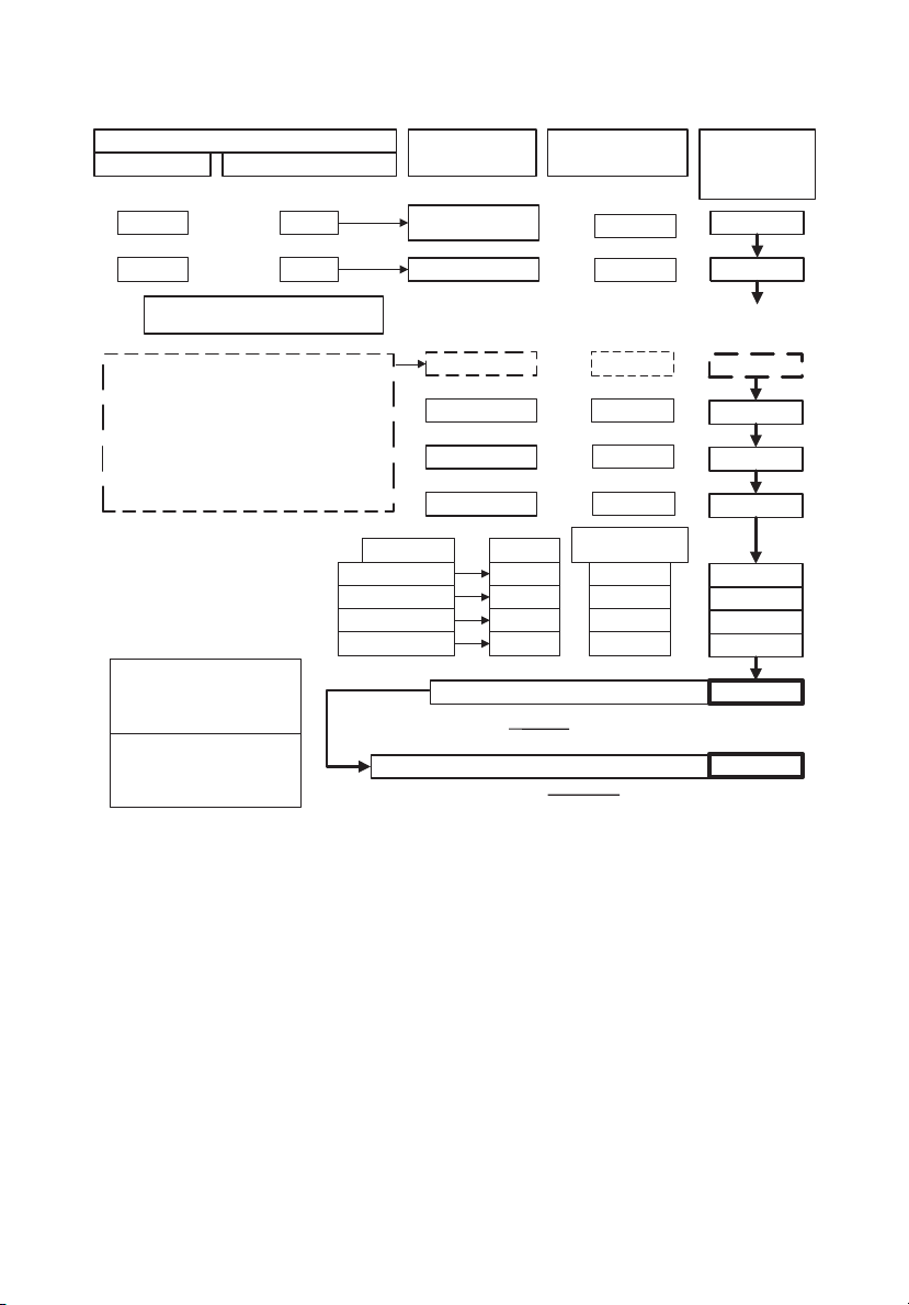
68- FR
A04669
CALCUL DE LA PUISSANCE EN WATTS
APPAREILS AYANT UNE CHARGE D'AMOR
PUSSANCE DE SERVICE EN WATTS
500
400
ÇAGE (INDUCTIVE) ÉLEVÉE
MULTIPLIÉE PAR (X) FACTEUR D'AMORÇAGE
x
x
2
2
MISE EN GARDE!!
NE PAS BRANCHER DE L'ÉQUIPEMENT ÉLECTRONIQUE
SENSIBLE À LA TENSION (TÉLÉVISEUR, ORDINATEUR ETC.)
DIRECTEMENT À LA GÉNÉRATRICE. SI LA GÉNÉRATRICE EST
UTILISÉE POUR ALIMENTER DE L'ÉQUIPEMENT SENSIBLE À LA
TENSION, IL FAUT UTILISER UN PROTECTEUR CONTRE LA
SURTENSION HOMOLOGUÉ U.L.
REMARQUE : SI AUCUN PROTECTEUR CONTRE LA SURTENSION
HOMOLOGUÉ U.L. N'EST UTILISÉ, L'ÉQUIPEMENT SERA
ENDOMMAGÉ ET LA GARANTIE SERA ANNULÉE
*POUR LES PRODUITS NE
FIGURANT PAS DANS LE TABLEAU,
SE RÉFÉRER AU PARAGRAPHE
«CALCUL DE LA PUISSANCE EN
WATTS».
**VALEURS MOYENNES - LES
TENSIONS RÉELLES DES
DIFFÉRENTS DISPOSITIFS
PEUVENT ÊTRE PLUS ÉLEVÉES OU
MOINS
ÉLEVÉES.
.
ÉCLAIRAGE
AMPOULES DE 60 WATTS
AMPOULES DE 75 WATTS
AMPOULES DE 100 WATTS
AMPOULES DE 300 WATTS
CE TOTAL DOIT ÉTRE INFÉRIEUR
CAPACITÉ NOMINALE EN WA TTS DE VOTRE GÉNÉRATRICE
CETTE CAPACITÉ DOIT ÊTRE SUPÉRIEURE AU TOTAL DES
CHARGES ÉLECTRIQUES RÉSIDENTIELLES EN WATTS
APPAREIL MÉNAGER OU
DISPOSITIF À CHARGE*
OUTIL À MAIN
AVEC CORDON
MÉLANGEUR
TÉLÉVISEUR
MICRO-ONDE
SÈCHE-CHEVEUX
PETIT VENTILATEUR
PUISSANCE EN WATTS
TYPIQUE DU DISPOSITIF**
=
=
=
=
WATTS
60
75
100
300
=
1000
=
800
300
800
800
42
MULTIPLIÉ PAR LE
NOMBRE D'AMPOULES
x
x
x
x
TOTAL DES CHARGES ÉLECTRIQUES
À LA CAPACITÉ DE VOTRE GÉNÉRATRICE
=
=
=
MISE EN GARDE!!
=
=
=
=
=
=
=
TOTAL
Page 69

69- FR
A04669
GUIDE DE DÉPANNAGE
PROBLÈME
CAUSE
CORRECTION
Le moteur ne
démarre pas
1. Niveau bas de carburant ou
d’huile.
2. Interrupteur « On/Off » du
moteur en position d'arrêt
« Off ».
3. Bougie d’allumage
défectueuse.
4. Étrangleur en mauvaise
position.
5. Levier de soupape de
carburant en position fermée.
6. Des charges électriques sur
l’appareil lors du démarrage.
7. Fil de la bougie d’allumage
desserré.
8. Conduite de carburant
obstruée.
9. Système d'allumage
défectueux.
1. Prise électrique défectueuse.
2. Disjoncteur déclenché.
3. Condensateur défectueux.
4. Cordon électrique défectueux.
1. Surcharge.
2. Cordons ou équipement
défectueux.
1. Génératrice surchargée.
2. Aération insuffisante.
1. Ajouter du carburant ou de l’huile.
2. Régler l'interrupteur à la position
de marche « ON ».
3. Remplacer la bougie d’allumage.
4. Régler l’étrangleur à la position
appropriée.
5. Placer le levier de soupape de
carburant à la position ouverte.
6. Débrancher toute charge
électrique de l’appareil.
7. Attacher le fil de la bougie
d’allumage.
8. Nettoyer la conduite de carburant
et le filtre à carburant.
9. Consulter un Centre de service
après-vente.
1. Faire remplacer par un Centre de
service après-vente.
2. Appuyer sur le disjoncteur pour le
rétablir.
3. Faire remplacer le condensateur
par un Centre de service aprèsvente.
4. Réparer ou remplacer le cordon
électrique.
1. Réduire la charge électrique.
2. Vérifier s’il y a des fils
endommagés, dénudés ou
effilochés sur l’équipement. Les
remplacer au besoin.
1. Réduire la charge électrique.
2. Déplacer l’appareil à un endroit
bien aéré.
Aucune
puissance
électrique
Le disjoncteur
déclenche
continuellement
La génératrice
surchauffe
Page 70

PIÈCES DE RECHANGE OFFERTES
N° de pièce Description
Z-A05449 Bouchon du réservoir à carburant
Z-A05451 Filtre à air
Z-A05453 Soupape d'arrêt de carburant
Z-A05454 Filtre à carburant
Z-A05458 Ensemble de tableau de commande
Z-A05459 Ensemble de génératrice
Z-A05460 Ensemble de moteur
Z-A05455 Bouchon de remplissage d'huile
Z-A05457 Pare-étincelles
Z-A05456 Condensateur
A04669
70- FR
Page 71

71- FR
A04669
GARANTIE LIMITÉE
DeVilbiss Air Power Company garantit à l'acheteur original, qui utilise le produit comme bien de consommation
(utilisé à des fins personnelles, résidentielles ou domestiques) que tous les produits couverts par cette garantie sont
exempts de défauts de matériaux et de fabrication pour une période d'un an à partir de la date d'achat. Tous les
produits couverts par cette garantie limitée qui sont utilisés à des fins commerciales (c.-à-d. produisant un revenu)
sont exempts de défauts de matériaux et de fabrication pour une période de 90 jours à partir de la date d'achat.
Les produits couverts par cette garantie comprennent les compresseurs d'air, les outils pneumatiques, les pièces de
rechange, les laveuses à pression et les génératrices.
DeVilbiss Air Power Company réparera ou remplacera, à sa discrétion, les produits ou composants s'étant avérés
défectueux dans les limites de la période de garantie. Les services seront effectués en respectant l'ordre normal des
travaux, lors d'une journée ouvrable, aux installations du Centre de service après-vente et selon la disponibilité des
pièces de rechange nécessaires. Toute décision prise par DeVilbiss Air Power Company en ce qui concerne cette
garantie limitée est finale.
Cette garantie vous donne certains droits particuliers. Il se peut que vous ayez d'autres droits, variant d'une
province à l'autre et d'un état à l'autre.
RESPONSABILITÉ DE L'ACHETEUR D'ORIGINE (utilisateur initial) :
• Pour faire une réclamation de garantie pour ce produit, NE retournez PAS le produit au détaillant. Le produit
doit être évalué par le personnel d'un Centre de service après-vente agréé. Pour connaître l'emplacement du
Centre de service après-vente agréé le plus près de chez vous, composez le
1-800-888-2468, 24 heures par jour, 7 jours par semaine ou visitez notre site Web à www.devap.com.
• Conservez le reçu de caisse original comme preuve d'achat pour toute réparation sous garantie.
• Appliquez tous soins raisonnables lors de l'utilisation et de l'entretien du produit, conformément aux
recommandations dans le ou les guide(s) de l'utilisateur.
• Livrez ou expédiez le produit au Centre de service après-vente agréé le plus proche. Le fret doit, le cas
échéant, être acquitté par l'acheteur.
• Les compresseurs d'air à réservoir de 60 et 80 gallons (227 et 303 litres) seront inspectés sur les lieux de leur
installation. Veuillez communiquer avec le Centre de service après-vente agréé le plus proche offrant le
service sur place, pour faire les arrangements nécessaires dans un tel cas.
• Tout acheteur qui n'est pas satisfait de l'intervention du Centre de service après-vente agréé est prié de
communiquer directement avec DeVilbiss Air Power Company.
CETTE GARANTIE NE COUVRE PAS CE QUI SUIT :
• Marchandise remise à neuf, utilisée comme équipement de location ou modèles de salon ou d'exposition.
• Marchandise ayant cessé de fonctionner en raison d'usure normale, d'usage abusif*, d'exposition au froid, à
la chaleur, à la pluie, à l'humidité excessive ou au gel, d'usage de produits chimiques non appropriés, de
négligence, d'accidents, de tout manquement à observer les directives d'utilisation du produit figurant dans le
ou les guide(s) de l'utilisateur fournis avec le produit, d'un entretien non approprié, de l'utilisation
d'accessoires ou de pièces non recommandées par DeVilbiss Air Power Company, ou de réparations ou de
modifications non approuvées.
* Un compresseur d'air pompant de l'air plus longtemps que le cycle de service recommandé durant
une période d'une heure peut être considéré comme ayant subi un usage abusif.
• Frais de réparation et de transport de marchandise non reconnue comme étant défectueuse.
• Coûts associés à l'assemblage, l'ajout nécessaire d'huile, les réglages ou autres frais d'installation et de mise
en marche.
• Pièces ou accessoires consommables, fournis avec le produit, et qui deviennent inutilisables ou inopérants
après une période raisonnable d'utilisation, y compris, mais sans être limités aux disques ou tampons de
ponçage, lames de scie et de ciseaux, pierres meulières, ressorts, burins, buses, joints toriques, gicleurs d'air,
rondelles et accessoires similaires.
• Marchandise vendue par DeVilbiss Air Power Company mais fabriquée par et identifiée comme étant le
produit d'une autre compagnie,tels que les moteurs à essence. Dans ce cas, la garantie du fabricant du
produit s'applique, si une telle garantie est offerte.
• TOUTE PERTE, TOUT DOMMAGE DIRECT OU INDIRECT OU TOUT FRAIS POUVANT RÉSULTER D'UN
DÉFAUT QUELCONQUE, D'UNE DÉFAILLANCE OU D'UN MAUVAIS FONCTIONNEMENT DU PRODUIT.
Certaines provinces et certains états ne permettent pas l'exclusion ni la limitation des dommages directs ou
indirects. Par conséquent, il se peut que les exclusions ou limitations mentionnées ci-dessus ne s'appliquent
pas dans votre cas.
• TOUTES GARANTIES IMPLICITES, Y COMPRIS CELLES PORTANT SUR LA VALEUR MARCHANDE ET
L'APPLICATION DU PRODUIT POUR UNE UTILISATION PARTICULIÈRE, SONT LIMITÉES À UN AN À
COMPTER DE LA DATE D'ACHAT D'ORIGINE. Certaines provinces et certains états ne permettent pas la
limitation de la période d'une garantie implicite. Par conséquent, il se peut que les limitations mentionnées
ci-dessus ne s'appliquent pas dans votre cas.
213 Industrial Drive • Jackson, TN 38301-9615
Téléphone : 1-800-888-2468
Télécopieur : 1-800-888-9036
Page 72

A04669
NOTES
 Loading...