

Page 1

Record All Information
for future reference:
Brand:
Purchase Date:
Model #:
Serial #:
Questions? 1-800-888-2468
Register your product online
www.devap.com
CONSUMER SAFETY INFORMATION . .2
SAFETY GUIDELINES/DEFINITIONS . .2
SAFETY INSTRUCTIONS . . . . . . . . . .2-8
ASSEMBLY . . . . . . . . . . . . . . . . . . . .8-13
OPERATION . . . . . . . . . . . . . . . . . .13-16
MAINTENANCE . . . . . . . . . . . . . . .16-17
STORAGE . . . . . . . . . . . . . . . . . . . .17-18
WATTAGE CALCULATIONS . . . . . . .18-20
TROUBLESHOOTING GUIDE . . . . . . .21
WARRANTY . . . . . . . . . . . . . . . . . . . . .22
QUICK FACTS . . . . . . . . . . . . . . . . . . .24
ESPAÑOL . . . . . . . . . . . . . . . . . . . . . . . . . . .25-48
FRANÇAIS . . . . . . . . . . . . . . . . . . . . . .49-72
READ AND SAVE THESE INSTRUCTIONS
Generator
Operator’s Manual
Part No. D26968 Rev. 0
Page 2

2- ENG
D26968
Read Operators Manual. Do not operate equipment until you have read
operators Manual for Safety, Assembly, Operation, and Maintenance
Instructions.
This product may not be equipped with a spark arresting muffler. If the
product is not equipped and will be used around flammable materials,
or on land covered with materials such as agricultural crops, forest, brush, grass, or other
similar items, then an approved spark arrester must be installed and is legally required in the
state of California. It is a violation of California statutes section 130050 and/or sections 4442
and 4443 of the California Public Resources Code, unless the engine is equipped with a spark
arrester, as defined in section 4442, and maintained in effective working order. Spark arrester
are also required on some U.S. Forest Service land and may also be legally required under
other statutes and ordinances.
Engine exhaust contains chemicals known, in certain quantities, to
cause cancer, birth defects or other reproductive harm.
CONSUMER SAFETY INFORMATION
CONSUMER GENERAL AND SERVICE INFORMATION
DO NOT RETURN THIS PRODUCT TO THE RETAILER! FOR SERVICE
OPTIONS CALL: 1-800-888-2468, EXT. 2.
• Please read and follow these instructions for proper use and maintenance.
• Please take the time now to register your generator online at
www.devap.com.
• If you experience any problems and need assistance, please call us at our toll
free number 1-800-888-2468, Monday through Saturday, 8:00 a.m. To 6:00
p.m. C.S.T.
• If repair or service part purchase is required, our many Authorized Warranty
Service Centers are conveniently located and equipped to handle all inwarranty and out-of-warranty service.
• For the location of the nearest Authorized Warranty Service Center call 1800-888-2468, Ext. 2, 24 hours a day, 7 days a week or visit our web site @
devap.com.
• Retain sales receipt as proof of purchase for warranty service.
• Read and understand all safety warnings.
• Do not operate this unit until you have read and understand this Owners
Manual for Safety, Operation, and Maintenance Instructions.
• Do not operate this unit until you have read and understand the Engine
Owners Manual for Safety, Operation, and Maintenance Instructions.
Note: Photographs and line drawings used in this manual are for reference only and
do not represent a specific model.
Page 3
3- ENG
D26968
indicates an imminently hazardous situation which, if not avoided, will result
in death or serious injury.
indicates a potentially hazardous situation which, if not avoided, could
result in death or serious injury.
indicates a potentially hazardous situation which, if not avoided,may result
in minor or moderate injury
used without the safety alert symbol indicates potentially hazardous
situation which, if not avoided, may result in property damage.
This manual contains information that is important for you to know and understand. This information relates to protecting YOUR SAFETY and PREVENTING EQUIPMENT PROBLEMS. To
help you recognize this information, we use the symbols below. Please read the manual and
pay attention to these sections.
SAFETY GUIDELINES / DEFINITIONS
IMPORTANT SAFETY INSTRUCTIONS
Improper operation or maintenance of this product could result in
serious injury and property damage. Read and understand all
warnings and operating instructions before using.
RISK OF ELECTROCUTION AND FIRE
HAZARD
WHAT CAN HAPPEN
HOW TO PREVENT IT
Attempting to
connect generator
directly to the
electrical system
of any building
structure.
Back feeding electricity through
a building’s electrical system to
the outside utility feed lines
could endanger repair persons
attempting to restore service.
Never backfeed electricity
through a structure's electrical
system.
Attempting to connect to the incoming utility service could result
in electrocution.
Restoration of electrical service
while the generator is connected
to the incoming utility could
result in a fire or serious damage
if an isolator switch is not
installed.
Failure to use a double throw
transfer switch when connecting
to a structure's electrical system
can damage appliances and
WILL VOID the manufacturer's
warranty.
To connect to a structure's electrical system in a safe manner,
always have a Double-Throw
Transfer Switch installed by a
qualified electrician and in compliance with local ordinances.
(When installing a DoubleThrow Transfer Switch, a minimum of 10 gauge wiring must
be used.)
Page 4
4- ENG
D26968
Operation of unit
when damaged,
or with guards or
panels removed.
Removal of guarding could
expose electrically charged
components and result in
electrocution.
Do not operate generator with
protective guarding removed.
Improper
connection of
items to
generator.
Exceeding the load capacity of
the generator by attaching too
many items, or items with very
high load ratings to it could
result in overheating of some
items or their attachment wiring
resulting in fire or electrical
shock.
Attempting to use the unit
when it has been damaged, or
when it is not functioning
normally could result in fire or
electrocution.
Read the load rating chart and
instructions in the Wattage Calculation section. Make sure that
the summation of electrical
loads for all attachments does
not exceed the load rating of the
generator.
Do not operate generator with
mechanical or electrical
problem. Have unit repaired by
an Authorized Service Center.
Operation of
generator in rain,
wet, icy, or
flooded
conditions.
Water is an excellent conductor
of electricity! Water which comes
in contact with electrically
charged components can
transmit electricity to the frame
and other surfaces, resulting in
electrical shock to anyone contacting them.
Operate generator in a clean, dry,
well ventilated area. Make sure
hands are dry before touching
unit.
Use of worn,
damaged, undersized or ungrounded extension cords.
Use of ungrounded cordsets
could prevent operation of
circuit breakers and result in
electrical shock.
Always use a cordset having a
grounding wire with an
appropriate grounding plug. DO
NOT use an ungrounded plug.
Use proper size (wire gauge)
cordset for application see chart
in the Assembly section of this
manual.
Contact with worn or damaged
extension cords could result in
electrocution.
Use of undersize extension
cords could result in overheating
of the wires or attached items,
resulting in fire.
Inspect extension cords before
use and replace with new cord if
required.
Placing generator
on or against
highly conductive
surface, such as a
steel walkway or
metal roof.
Place generator on low conductivity surface such as a concrete
slab.
Accidental leakage of electrical
current could charge conductive
surfaces in contact with the
generator.
RISK OF ELECTROCUTION AND FIRE
(Continued)
HAZARD
WHAT CAN HAPPEN
HOW TO PREVENT IT
ALWAYS operate generator a
minimum of six feet from any
conductive surface.
Page 5
5- ENG
D26968
RISK OF FIRE
HAZARD
WHAT CAN HAPPEN
HOW TO PREVENT IT
Improper storage
of fuel
Improperly stored fuel could
lead to accidental ignition. Fuel
improperly secured could get
into the hands of children or
other unqualified persons.
Store fuel in a OSHA approved
container designed to hold
gasoline. Store container in secure location to prevent use by
others.
Attempting to
fill the fuel tank
while the engine
is running.
Gasoline and gasoline vapors
can become ignited by coming
in contact with hot components
such as the muffler, engine
exhaust gases, or from an
electrical spark.
Cigarettes, sparks, fires, or
other hot objects can cause
gasoline or gasoline vapors to
ignite.
Turn engine off and allow it to
cool before adding fuel to the
tank. Equip area of operation
with a fire extinguisher certified
to handle gasoline or fuel fires.
Add fuel to tank in well
ventilated area. Make sure there
are no sources of ignition near
the generator.
Operate generator in a clean, dry,
well ventilated area a minimum of
four feet from any building, object
or wall. DO NOT OPERATE
UNIT INDOORS OR IN ANY
CONFINED AREA.
Materials placed against or near
the generator or operating the
generator in areas where the
temperature exceeds 104° F. ambient (such as storage rooms or
garages) can interfere with its
proper ventilation features causing overheating and possible ignition of the materials or buildings.
Sparks, fire, hot
objects
Inadequate
ventilation for
generator
Tampering with
factory set
engine speed
settings.
Engine speed has been factory
set to provide safe operation.
Tampering with the engine speed
adjustment could result in
overheating of attachments and
could cause a fire.
Spilled fuel and its vapors can
become ignited from hot
surfaces or sparks.
Never attempt to “speed-up”
the engine to obtain more performance. Both the output
voltage and frequency will be
thrown out of standard by this
practice, endangering
attachments and the user.
Use care in filling the tank to
avoid spilling fuel. Make sure
fuel cap is secured tightly and
check engine for fuel leaks
before starting engine. Move
generator away from refueling
area or any spillage before
starting engine. Allow for fuel
expansion. Keep maximum fuel
level ¼ inch below the tip of the
fuel tank. Never refuel with the
engine running.
Overfilling the fuel
tank – fuel
spillage.
Page 6
6- ENG
D26968
RISK OF UNSAFE OPERATION
HAZARD
WHAT CAN HAPPEN
HOW TO PREVENT IT
Operation of
generator in
careless manner
All sources of energy include the
potential for injury. Unsafe
operation or maintenance of your
generator could lead to serious
injury or death to you or others.
• Review and understand all of
the operating instructions and
warnings in this manual.
• Become familiar with the operation and controls of the
generator. Know how to shut it
off quickly.
• Equip area of operation with a
fire extinguisher certified to
handle gasoline or fuel fires.
• Keep children or others away
from the generator at all times.
RISK OF BREATHING - INHALATION
HAZARD
HAZARD
WHAT CAN HAPPEN
HOW TO PREVENT IT
Breathing exhaust fumes will
cause serious injury or death.
Operate generator in clean, dry,
well ventilated area. Never
operate unit in enclosed areas
such as garages, basements,
storage, sheds, or in any
location occupied by humans or
animals. Keep children, pets and
others away from area of operating unit.
Gasoline
engines produce
toxic carbon
monoxide
exhaust fumes.
RISK OF INJURY AND PROPERTY
DAMAGE WHEN TRANSPORTING
GENERATOR
HAZARD
WHAT CAN HAPPEN
HOW TO PREVENT IT
Fire, Inhalation,
Damage to
Vehicle Surfaces
Fuel or oil can leak or spill and
could result in fire or breathing
hazard, serious injury or death
can result. Fuel or oil leaks will
damage carpet, paint or other
surfaces in vehicles or trailers.
If generator is equipped with a
fuel shut-off valve, turn the valve
to the off position before
transporting to avoid fuel leaks.
If generator is not equipped with
a fuel shut-off valve, drain the
fuel from tank before transporting. Transport fuel only in an
OSHA approved container.
Always place generator on a
protective mat when transporting to protect against damage to
vehicle from leaks. Remove
generator from vehicle immediately upon arrival at your destination.
Page 7
7- ENG
D26968
RISK OF UNSAFE OPERATION
(Continued)
HAZARD
WHAT CAN HAPPEN
HOW TO PREVENT IT
Improper raising or suspending
can cause damage to the
generator.
Always use cables, chains, or
straps rated at 2000 lbs working
load or more to raise or suspend
generator.
Operation of
voltage
sensitive appliances without a
voltage surge
protector
Any gasoline operated
household generator will incur
voltage variations causing
damage to voltage sensitive appliances or could result in fire.
Always use a U.L. listed voltage
sensitive surge protector to
connect voltage sensitive
appliances (TV, computer, stereo, etc.). Failure to use a U.L.
listed voltage surge protector
will void the warranty on your
generator.
Notice: A multiple outlet strip is
not a surge protector. Make sure
you use a U.L. listed voltage
surge protector
Raising or
suspending
generators
equipped with
lift rings
improperly
Generator could fall causing
serious injury or death to you or
others.
Always use proper connecting
procedures as described in this
manual when connecting cables,
chains, or straps for raising or
suspending generators equipped
with lift rings.
Operating
generator while
suspended
Generator will not operate
properly and will cause damage
to the generator and could
cause serious injury or death to
you or others.
Never operate generator while
suspended or in an unlevel
position. Always operate
generate on a flat, level surface.
Contact with hot surfaces, such
as engines exhaust components,
could result in serious burns.
RISK OF HOT SURFACES
HAZARD
WHAT CAN HAPPEN
HOW TO PREVENT IT
Contact with hot
engine and
generator
components.
During operation, touch only the
control surfaces of the
generator. Keep children away
from the generator at all times.
They may not be able to recognize the hazards of this
product.
Page 8
8- ENG
D26968
NOTE: This manual is a general manual. Information in this manual may or
may not pertain to your model. Please read carefully.
NOTE: Left and right describes the location of a part with the operator
facing the outlet panel.
ASSEMBLY
Read this manual. Do not attempt to operate equipment
until you have read this Manual for Safety, Operation, and
Maintenance Instructions.
HAZARD
WHAT CAN HAPPEN
HOW TO PREVENT IT
HAZARD
WHAT CAN HAPPEN
HOW TO PREVENT IT
RISK OF MOVING PARTS
Never operate generator with
guarding or cover plates
removed. Avoid wearing loose
fitting clothing or jewelry which
could be caught by moving parts.
The generator contains parts
which rotate at high speed during
operation. These parts are
covered by guarding to prevent
injury.
Contact with
moving parts
can result in
serious injury.
RISK FROM LIFTING
The generator is too heavy to be
lifted by one person. Obtain assistance from others before you
try to move it.
Serious injury can result from attempting to lift too heavy an
object.
Lifting a very
heavy object.
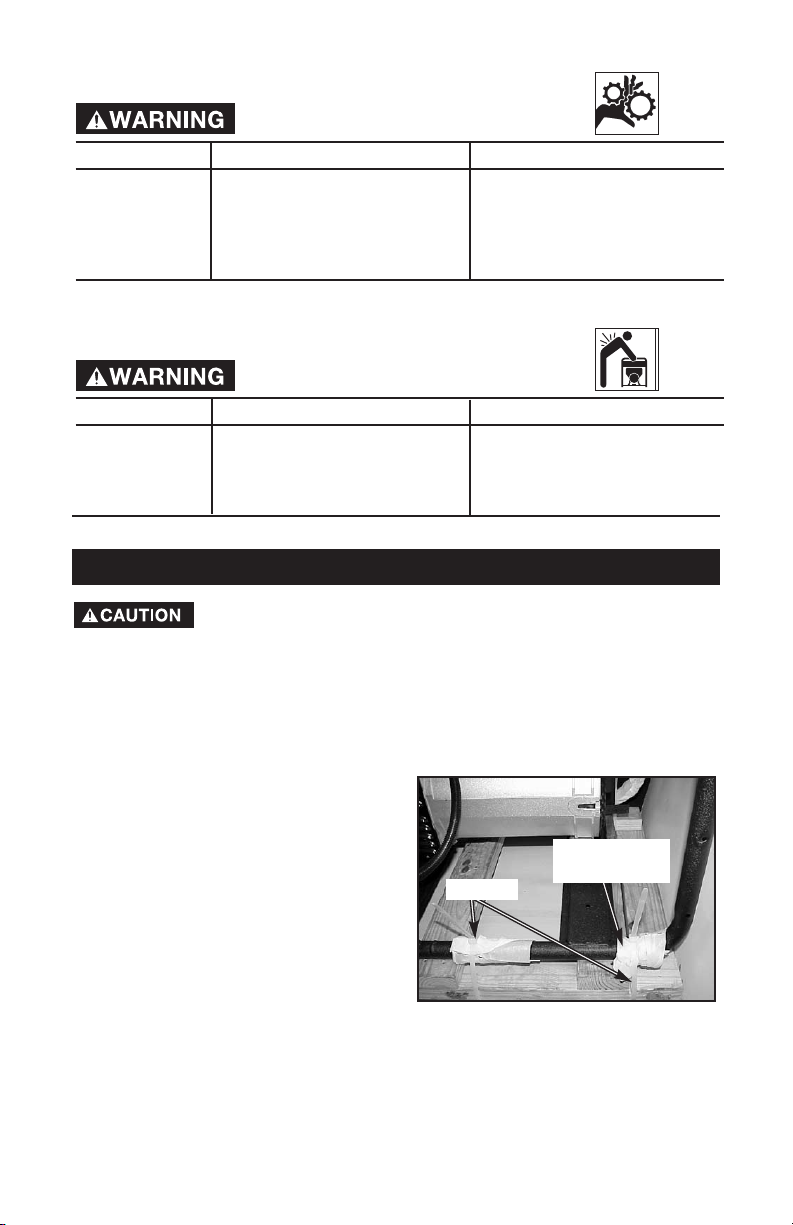
UNPACKING
1. Locate the parts carton and set aside
for later use.
2. Cut wire ties holding generator to
pallet and remove protective
wrapping.
3. Remove all packaging, leaving
generator on pallet.
IMPORTANT: DO NOT remove generator
from pallet.
4. Discard all packaging.
Wire Tie
Protective
Wrapping
Page 9
9- ENG
D26968
ASSEMBLE WHEEL KIT
Tools needed:
2 - 2x4 at least 30” long
1 - 1/2” socket
1 - 1/2” open end wrench
1 - hammer
1 - pliers
Parts bag contains:
2 - Handle Grips
2 - Handle End Caps
4 - Screws, .313-18X1.75
1 - Cotter Pin
2 - Washers, 5/8" X 1.32 X .09
1 - Flat Steel Washer
2 - Axle Spacer
2 - Cap Screw 5/16-18 X 3/4
6 - Flange Nuts
2 - Wheel Brackets
1 - 5/8” Axle Cap
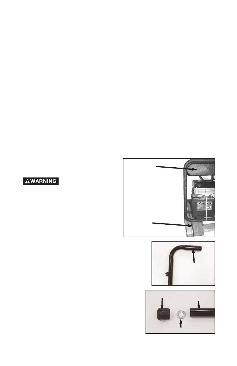
1. Lift the gas tank end of generator
and slide 2x4 between generator
and pallet as shown.
The generator is too
heavy to be lifted by
one person. Obtain assistance from
others before lifting.
2. Place handle grips on handle assemblies.
3. Place one 5/8” washer into the bottom of
each end cap. Push end caps onto the
end of the handle assemblies.
2x4
Gas Tank
Handle Grip
End Cap
5/8” Washer
Handle
Assembly
Page 10
10- ENG
D26968
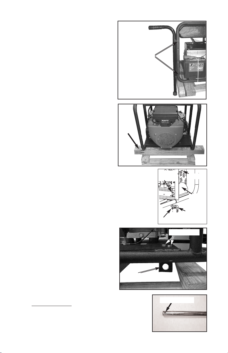
4. Attach handle assemblies to frame
using four screws and flange nuts.
NOTE: Screw on outside of frame.
NOTE: Do not tighten until all screws
and flange nuts are assembled.
5. Lift generator and remove 2x4.
6. Lift other end of generator and place
two 2x4s between generator and
pallet as shown.
7. On the muffler side of the engine, remove cap screws
and flange nuts holding the heat shield to the frame.
Reassemble cap screws, heat shield, wheel bracket,
and flange nuts and as shown. Tighten securely.
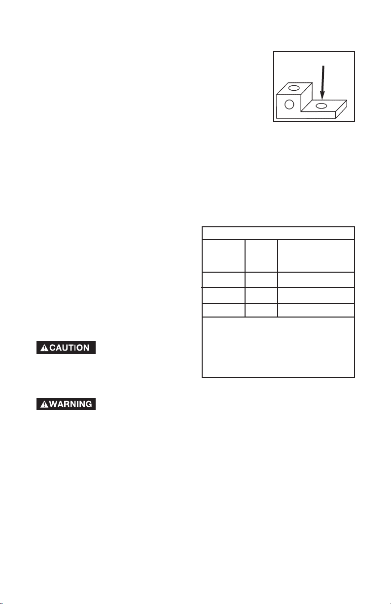
8. On other side, assemble wheel
bracket using cap screws and flange
nuts supplied. Tighten securely.
NOTE: Brackets are placed under frame
with hole facing outward.
9. Using a hammer tap axle cap onto end of axle,
without the hole
.
10. Slide wheel onto axle with valve stem to the
outside.
11. Slide spacer onto axle against wheel.
Cap screws
Wheel Bracket
Hole in Axle
Muffler
Heat
Shield
Cap
Screw
Wheel
Bracket
Flange Nuts
Screws and
Flange Nuts
2x4
Page 11

11- ENG
D26968
12. Slide axle through axle brackets. NOTE: The pallet will need to be
removed before the wheel can be assembled.
13. Lift generator and slide pallet and 2x4s out. NOTE: Generator will tilt.
14. Lift generator and slide spacer, then wheel (with valve stem to the outside)
onto axle.
15. Slide flat steel washer onto axle against wheel.
16. Secure with cotter pin.
BATTERY INSTALLATION
The generator is equipped with a maintenance free battery.
1. For packaging purposes the black
negative battery cable and battery
were secured with wire ties. Cut
these wire ties.
2. Connect black negative cable to
negative (-) battery post. Tighten
securely. NOTE: Make sure rubber
boot is covering positive (+) battery
terminal.
NOTE: If battery needs to be charged,
follow these instructions.
When charging the
battery, do not smoke.
Keep away from any sparks. The
fumes from the battery acid can cause
an explosion. To prevent explosive
fumes from accumulating do not
charge in an enclosed area.
Sulfuric acid is a
flammable and
explosive chemical that is harmful to
the skin, eyes, and clothing.
To prevent sparks,
disconnect the black
battery cable from the negative (-)
terminal before disconnecting the red positive cable.
1. Remove black negative battery cable from the battery.
2. Remove red positive battery cable from the battery.
3. Use a portable 12 volt battery charger, if needed, to bring battery to full
charge (12.6 at 70ºF.). Refer to the battery charger’s operator’s manual for
the correct procedure. If a battery charger is not available, have an
authorized service center charge the battery.
4. Connect the battery cables.
To Prevent sparks connect the red (positive) cable to the
positive (+) terminal before connecting the black negative
cable.
When transporting unit over extremely rough terrain by
vehicle the battery should be secured.
Positive
Battery
Cable with
rubber boot
Negative
Battery
Cable
Negative
Battery
Cable
Wire Tie
Wire Tie
Page 12
12- ENG
D26968
EXTENSION CORDS
When using an appliance or tool at a
considerable distance from the generator,
a 3-wire extension cord that has a 3blade grounding plug and a 3-slot receptacle that accepts the tool's plug MUST
be used in order to reduce the risk of
electrical shock. A cord of adequate size
must be used. Using the following chart
to determine the minimum wire size required.
An extension cord that
is hot to the touch is
overloaded. Repair or replace
damaged extension cords immediately.
DOUBLE THROW TRANSFER SWITCH
Potential hazards exist when a portable electric generator is
connected to the main electrical supply coming into the house.
It is at that point that the electrical generator could feed back into the utility
company's system causing possible electrocution of workers who are repairing
the electrical lines.
To avoid back feeding of electricity into utility systems, a double-throw transfer
switch must be installed between the generator and utility power. The DoubleThrow Transfer Switch should be installed by a licensed electrician and in compliance with all state and local electrical codes. (When installing a Double-
Throw Transfer Switch, a minimum of 10 gauge wiring must be used.)
The electrician should also install a sub-panel to isolate the circuits you would
want to use during an emergency or electrical power outage. Your generator will
not be large enough to handle the load of all the lights, appliances, TV, etc. at
one time. To select which items to run during the electrical power outage, see
Wattage Calculation section in this manual.
GROUNDING THE GENERATOR
A grounding lug is supplied with the generator for use
when required by local electrical ordinances. Refer to
article 250 of the National Electrical Code to clarify any
needed grounding information. Your local electric company
or a certified electrician should be able to help you with
this information.
Grounding Lug
Extension Cord Wire Gauge Chart
Amperage
Cord
Length
Wire
Gauge
Size
1. When amperage exceeds 20 amp; a
12 gauge extension cord should not
be used for long distances.
2. When amperage exceeds 30 amp; a
10 gauge extension cord should not
be used for long distances.
0 to 100 ft.
0 to 100 ft.
12 ga.
10 ga.
1
Up to 20 amp draw
2
Up to 30 amp draw
0 to 100 ft.
8 ga. Up to 40 amp draw
OBTAINING ELECTRICITY FROM THE GENERATOR
There are basically 2 ways to obtain electricity from a generator:
1. Use of extension cords directly from the generator to the appliance, lights,
tools, etc.
2. Use of a double-throw transfer switch installed directly to the main electrical
supply outside of house.
Page 13

13- ENG
D26968
OTHER LOOSE PARTS
1. Oil is supplied, see engine operator’s manual for correct procedure to add oil
and fuel to engine.
2. The locking plugs maybe used when needed or required.
The locking plugs are to be installed and/or used in
accordance with appropriate local electrical code
regulations. Refer to instructions enclosed with each plug for proper
installation.
3. 12V DC cables to be used with the 12V DC outlets. See Operation section.
IMPORTANT: Before any attempt to start your generator be sure to check
engine oil (See Engine Operator's manual)
KNOW YOUR GENERATOR
Read this General Manual and Safety Rules before operation of your Generator.
Compare the illustration in your parts manual with your generator to familiarize yourself with
the location of various controls and adjustments. Save all manuals for future references.
GENERATOR CAPACITY
IMPORTANT: Exceeding the rated capacity of your generator can result in serious damage
to your generator and connected electrical devices. See the Wattage Calculation section in
this manual to assist you in determining the appliances and tools that can be run with the
wattage capacity of your generator.
CIRCUIT BREAKERS
Each receptacle has a circuit breaker to protect the generator from overloading. If the circuit
breaker trips, unplug all electrical loads from the generator. Let the circuit breaker cool
down. Push circuit breaker button to reset.
LOW OIL SHUTDOWN
Your generator engine is equipped with Low Oil Shutdown. Low Oil Shutdown is
a safety device designed to protect your engine from damage in the event the oil
level in the crankcase is low.
If while the engine is running, the oil gets low, it will automatically shut itself
down and will not restart until the oil is added. If the oil is low before start-up,
the generator will not start until oil is added.
NOTE: The Low Oil Shutdown mechanism is very sensitive. You must fill the
engine to the full mark on the dipstick to inactivate this safety device.
OFF/RUN/START SWITCH
Placed in the start position to start engine and the off position to stop engine.
NOTE: When engine is running switch will remain in the run position.
OPERATION
Page 14
14- ENG
D26968
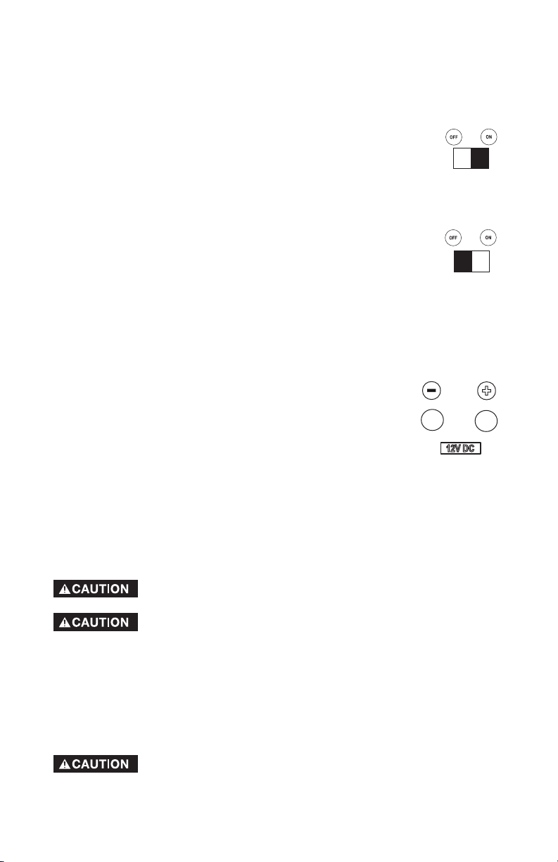
IDLE CONTROL
Choose the correct application.
1. For normal application such as power tools, small electric appliances, light
bulbs, and radios:
Place the idle control switch in the ON position. The generator
will idle down when there is no load. This lowers the engine
noise, saves on fuel consumption, and engine life.
2. Idling down IS NOT recommend on large motors (refrigerators, freezers, etc)
or voltage sensitive electronic equipment (computers, televisions, etc). For
these applications:
Place the idle control switch in the OFF position.
12V DC OUTLET
IMPORTANT: Allow generator to run at no load for 5 minutes upon each initial
start-up to allow engine to stabilize.
IMPORTANT: When the unit is running the battery will charge. DO NOT
connect the 12V DC cables to the generator’s battery.
To charge battery:
1. Using the 12V DC cables supplied, connect the red
positive (+) 12V DC cable to the battery's positive (+)
terminal.
2. Attach the other end of the red positive (+) 12V DC cable
to the generators positive (+) 12V DC outlet.
3. Connect the black negative (-) 12V DC cable to the battery's negative (-)
terminal.
4. Attach the other end of the black negative (-) 12V DC cable to the
generators negative (-) 12V DC outlet.
5. Charge the battery according to battery or equipment manufacturer
recommendations.
BEFORE START UP
This generator has been shipped from the factory without oil in the
crankcase. Operating the unit without oil can damage the engine.
Always check engine oil level before every start. Running engine
low of oil or out of oil could result in serious damage to the engine.
Follow the steps listed below before starting generator:
1. Check engine oil. Refer to the Engine Operator's Manual for correct grade and quantity
of oil.
2. Check fuel level, fill as required. Make sure generator is turned off and has been allowed
time to cool down. Use clean, fresh, regular unleaded gasoline with a minimum of 87
octane. Do not mix oil with gasoline.
Never fill fuel tank completely. Fill tank to 1/2" below the bottom of
the filler neck to provide space for fuel expansion. Wipe any fuel
spillage from engine and equipment before starting engine.
Page 15

15- ENG
D26968
TO START THE ENGINE
Never run engine indoors or in enclosed, poor ventilated
areas, engine exhaust contains carbon monoxide, an
odorless and deadly gas.
1. Open the fuel shut-off valve.
2. Move the choke control located on the engine to "CHOKE"
position. A cold engine may require to be choked longer
than a warm engine.
3. Push ON\OFF\START switch on control panel to the
"START" position to start engine. Hold in "START" position
no longer than 15 seconds per minute when trying to start
engine. Extended cranking can damage the starter motor.
4. When engine starts, gradually move the choke to the "NO Choke" position.
IMPORTANT: Allow generator to run at no load for 5 minutes upon each initial
start-up to allow engine and generator to stabilize.
STOPPING ENGINE
1. Disconnect all electrical loads.
2. Place the ON\OFF\START switch to "OFF" position.
3. Close fuel shut-off valve.
CONNECTING ELECTRICAL LOADS
1. Let engine run and warm up for five minutes after starting with no electrical
load.
Connect loads in the following manner to prevent damage to equipment:
2. Connect inductive load equipment first, inductive loads consist of
refrigerators, freezers, water pumps, air conditioners, or small hand tools.
Connect the items that require the most wattage first. See Wattage Calcu-
lation Section in this manual.
3. Connect the lights next.
Never fill fuel tank indoors. Never fill fuel tank when engine is
running or hot. Do not smoke when filling fuel tank.
Never run engine indoors or in enclosed, poor ventilated areas, engine exhaust contains carbon monoxide, an odorless and deadly
gas.
3. Make sure generator is grounded in accordance with local requirements.
4. All electrical loads MUST be disconnected.
5. Idle control switch must be in the OFF position.
Engine speed has been factory set to provide safe operation.
Tampering with the engine speed adjustment could result in overheating of attachments and could cause a fire. Never attempt to “speed-up” the engine to obtain more performance. Both the output voltage and frequency will be
thrown out of standard by this practice, endangering attachments and the user.
You MUST unplug any load from the generator before starting to
prevent permanent damage to any appliances.
Page 16

16- ENG
D26968
Note 1: Change oil after first two (2) operating hours and every 50 operating
hours thereafter, more often if operated in extreme dusty or dirty conditions.
Note 2: Check oil after 5 hours of operation.
CUSTOMER RESPONSIBILITIES TABLE
MAINTENANCE TASK
Before
each
use
Every 25
Hours of
Every
Season
Every 50
Hours of
Every
Season
Every 100
Hours of
Every
Season
Check Spark Plug
Prepare unit for storage if it is to remain
idle for more than 30 days.
MAINTENANCE
Check oil level
Change oil
Clean Air Filter Assembly
Prepare Unit for Storage
See Note 2
X
See Note 1
X
X
X
GENERAL RECOMMENDATIONS
The warranty of the generator does not cover items that have been subjected to
operator abuse or negligence. To receive full value from the warranty, operator
must maintain the generator as instructed in this manual.
ENGINE MAINTENANCE
Refer to the Engine Operator's manual for service and maintenance of the
engine.
4. Voltage sensitive equipment should be the last equipment connected to the
generator. Plug voltage sensitive appliances such at TV's, VCR's, microwaves, ovens, computers, and cordless telephones into a UL listed voltage
surge protector, then connect the UL listed voltage surge protector to the
generator.
Failure to connect and operate equipment in this sequence
can cause damage to equipment and will void the warranty
on your generator.
Follow the wattage calculation table in the Wattage Calculation section of
this manual. Overloading the generator will cause power fluctuations and
can damage equipment and appliances.
DeVilbiss Air Power Company will only be responsible for damage to
customer's equipment when the generator is determined to be defective.
This determination will only be made by an authorized representative of
DeVilbiss Air Power Company and this decision will be final. DeVilbiss Air
Power Company reserves the right to inspect the electrical connections at
the customer's site of operation and test the generator for proper operation before any determination of liability is made. Failure to maintain the
equipment or wiring for inspection will void any claim for damages by the
customer. DeVilbiss Air Power Company will not be responsible for
equipment damaged as a result of voltage surges, improper operation or
improper installation of the generator.
Page 17

17- ENG
D26968
If you are going to store your generator for more than 30 days, use the
following information as a guide to prepare the generator for storage.
Never store generator with fuel in the tank indoors or in
enclosed, poorly ventilated areas, where fumes can reach
an open flame, spark or pilot light as on a furnace, water heater, clothes
dryer or other gas appliances.
ENGINE PREPARATION
1. Add fuel stabilizer to fuel tank to minimize the formation of fuel gum
deposits during storage.
2. Run engine at least 10 minutes after adding stabilizer to allow it to enter the
fuel system.
3. Next shut off engine.
4. Disconnect the spark plug wire and remove the spark plug.
5. Add one teaspoon of oil through the spark plug hole.
6. Place rag over spark plug hole and pull the recoil a few times to lubricate
the combustion chamber.
7. Replace the spark plug, but do not connect the spark plug wire.
NOTE: If a fuel stabilizer is not used, all gasoline must be drained from the tank
and carburetor to prevent gum deposits from forming on these parts and causing
possible malfunction of the engine.
GENERATOR
• Clean the generator as outlined in the Maintenance Section on this manual.
• Check that cooling air slots and openings on generator are open and
unobstructed.
STORAGE
GENERATOR MAINTENANCE
Your generator should be kept clean and dry at all times. The generator should
not be stored or operated in environments that includes excessive moisture,
dust or any corrosive vapors. If these substances are on the generator, clean
with a cloth or soft bristle brush. Do not use a garden hose or anything with
water pressure to clean the generator. Water may enter the cooling air slots and
could possibly damage the rotor, stator and the internal windings of the gen
head.
GROUND FAULT CIRCUIT INTERRUPTER GFCI RECEPTACLE
MONTHLY: For maximum protection against electrical shock the GFCI should
be tested monthly.
To test:
1. Depress the TEST button. The RESET button should extend. If the RESET
button does not extend, notify a DeVilbiss Air Power Company Authorized
Warranty Service Center.
2. To restore power, depress the RESET button firmly into the GFCI unit until an
audible click is heard. If reset properly, the RESET button is flush with the
surface of the test button. When the button stays in, the power is ON.
Page 18
18- ENG
D26968
BATTERY
• Store battery as described by the battery manufacturer.
NOTE: After storing battery for a long period of time it may lose its charge. If
the battery loses its charge, manually start the engine with the battery connected. The engine will recharge the battery as it runs.
WATTAGE CALCULATIONS
Never exceed the rated capacity of your generator. Serious damage to the
generator or appliance could result from an overload.
1. Starting and running wattage requirements should always be calculated
when matching a generators wattage capacity to the appliance or tool.
2. There are two types of electrical appliances that can be powered by
your generator:
A. Items such as radios, light bulbs, television sets, and microwaves
have a "resistive load". Starting wattage and running wattage are
the same.
B. Items such as refrigerators, air compressors, washer, dryer, and
hand tools that use an electrical motor have an "inductive load".
Inductive load appliances and tools require approximately 2 to 4
times the listed wattage for starting
the equipment. This initial load
only lasts for a few seconds on start-up but is very important when
figuring your total wattage to be used.
C. Always start your largest electric motor first, and then plug in other
items, one at a time.
NOTE: On 120-volt loads the maximum starting wattage should NOT
exceed one half of the rated generator wattage. Example: a 5000 rated
wattage generator = 2500 maximum starting wattage.
IMPORTANT
DETERMINING WATTAGE REQUIREMENTS
Before operating this generator list all of the appliances and/or tools that are
going to operate at the same time. (Then determine the starting wattage
requirements and the running wattage requirements by following example
and/or refer to household wattage calculator.)
1. First total the running wattage of all appliances and/or tools that will be
operated at the same time.
Running W
atts Starting Watts
Example 1:
Lights = 100 Watts 0
Television = 300 Watts 0
Slow Cooker = 250 W
atts 0
TOTAL =650 Watts 0
2. Next the starting wattages of any appliances and/or tools that will start and
stop during operation.
Running W
atts Starting Watts
Example 2:
Small Refrigerator 500 W
atts 2000 Watts
TOTAL =500 Watts 2000 Watts
Page 19

19- ENG
D26968
3. The running wattage of examples 1 & 2 totals 1150 watts. The starting
wattage of the small refrigerator is 2000 watts which is 1500 watts more
than the running watts. Take this difference of 1500 starting watts from the
refrigerator and add to the total running watts of 1150.
Example 3: 1500 Starting Watts
1150 Running W
atts
TOTAL =2650 Total Watts
Generator must have a maximum capacity of at least 2650 watts.
STARTING WATTAGE REQUIREMENTS
1. Some appliances and tools will list on the motor nameplate the starting
and running voltage and amperage requirements. Use the following
formula to convert voltage and amperage to wattage:
Volts X Amp = Watts
Example: 120 volts x 10 amps = 1200 watts
2. To determine the approximate starting wattage requirement for most
appliances and tools with inductive type motors, multiply the wattage that
was calculated by 2 to 4 times to assure adequate generator capacity. If
the nameplate information is not available use the values on the following
chart as a guide.
3. Remember that the starting and running wattage for resistive loads are the
same. (Example: a 100 watt light bulb requires only 100 watts to start.)
Most resistive loads will
be listed in wattage.
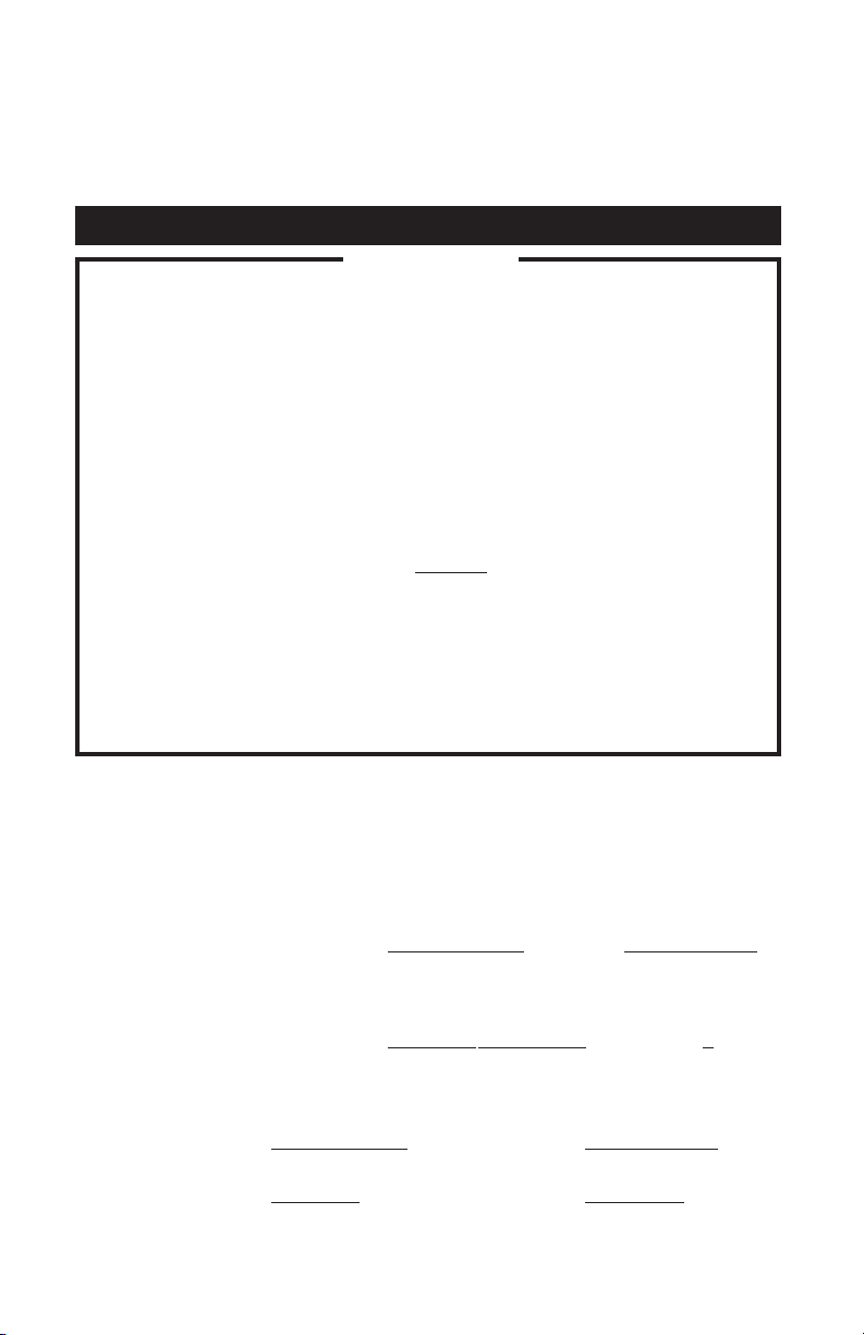
Application Guide
3/8” Hand Drill
Jigsaw
(1/3 HP) Airless Sprayer
6” Bench Grinder
Belt Sander
Demolition Hammer
7-1/4” Circular Saw
(Small) Air Compressor
Light Bulb
Home Security
Television
Microwave
Toaster Oven
(5,000 BTU) Portable Heater
Furnace Fan
Refrigerator/Freezer
Sump Pump
Clothes Washer
Water Heater
(30,000 BTU) Air Conditioner
(12V DC) Battery Charger
Radio
Slow Cooker
Electric Blanket
Electric Skillet
Coffee Maker
Small Refrigerator
The wattage ratings
shown are averages actual wattage may vary.
To select the right generator for
your needs, total the wattage of the
items to be run at the same time.
1000
100
250
500
2000
WATTAGE Run Start
3000
4000
5000
6000
7000
8000
9000
10000
Page 20
20- ENG
D26968
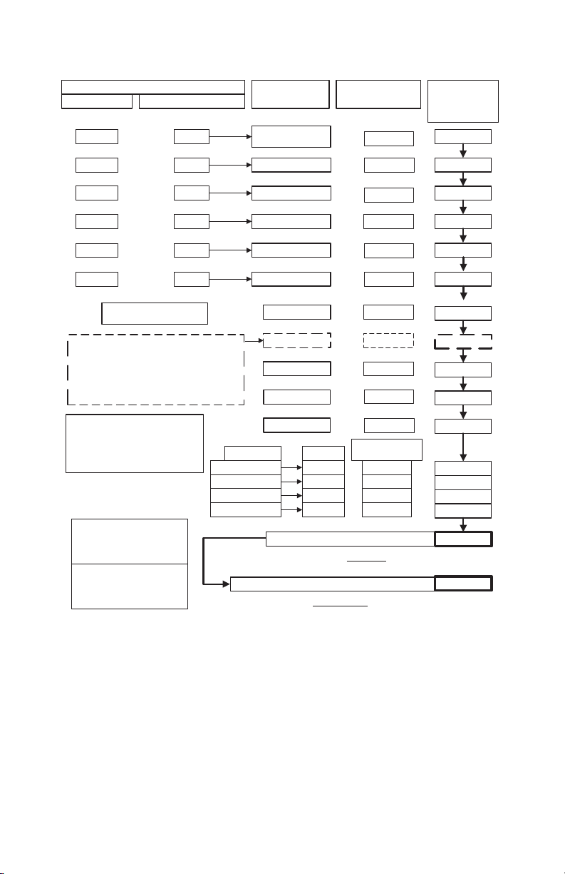
HOUSEHOLD WATTAGE CALCULATOR
DEVICES WITH HIGH STARTING (INDUCTIVE)LOADS
RUN WATTS
800
600
2400
1000
800 3
1000 2
TIMES (X) START FACTOR
x
x
x
x
3
3
3
2
x
x
CAUTION !!
DO NOT CONNECT VOLTAGE SENSITIVE
ELECTRONIC EQUIPMENT (TV SET, COMPUTER,
ETC.) DIRECTLY TO YOUR GENERATOR. IF YOU USE
THE GENERATOR TO POWER SENSITIVE EQUIPMENT
YOU MUST USE A U.L. LISTED VOLTAGE SURGE
PROTECTOR.
NOTICE: FAILURE TO USE A U.L. LISTED VOLTAGE
SURGE PROTECTOR WILL DAMAGE YOUR
EQUIPMENT AND VOID YOUR WARRANTY.
THE IDLE CONTROL MUST BE IN THE
OFF POSITION WHEN OPERATING
LARGE MOTOR LOADS (FREEZERS,
REFRIGERATORS,ETC.) OR VOLTAGE
SENSITIVE ELECTRONIC EQUIPMENT
(TV, COMPUTERS, ETC.)
*FOR PRODUCTS NOT
LISTED REFER TO
CALCULATION
INSTRUCTIONS
**AVERAGE VALUES -
ACTUAL INDIVIDUAL
DEVICE VOLTAGES MAY
BE HIGHER OR LOWER
LIGHTING
60 WATT BULBS
75 WATT BULBS
100 WATT BULBS
300 WATT BULBS
WATTAGE RATING OF YOUR GENERATOR
THIS TOTAL MUST BE GREATER THAN YOUR HOUSEHOLD WATTAGE LOAD
APPLIANCE OR
LOAD DEVICE*
REFRIGERATOR/
FREEZER
SMALL REFRIGERATOR
AIR COND.(ROOM)
SUMP PUMP 1/2 HP
FURNACE FAN 1/3 HP
WELL PUMP 1/2 HP
HOT PLATE
TELEVISION
MICROWAVE
SPACE HEATER
WATER HEATER
WATTS
60
75
100
300
TYPICAL DEVICE
WATTAGE**
=
2400
=
1800
=
7200
2000
=
=
2400
=
2000
=
1500
=
300
800
=
1500
=
4000
=
TIMES NUMBER
OF BULBS
x
x
x
x
=
=
=
=
=
=
=
=
=
=
=
=
=
=
=
ELECTRIC LOAD GRAND TOTAL
THIS TOTAL MUST BE LESS THAN YOUR GENERATOR RATING
TOTAL
CAUTION !!
Page 21

21- ENG
D26968
TROUBLESHOOTING GUIDE
PROBLEM
CAUSE
CORRECTION
Engine will not
start
1. Low on fuel or oil.
2. Ignition switch in "Off"
position.
3. Faulty spark plug.
4. Choke in wrong position.
5. Fuel shut-off valve in
closed position
6. Unit loaded during start-
up.
1. Add fuel or oil.
2. Turn to "ON" position
3. Replace spark plug.
4. Adjust choke accordingly.
5. Open fuel shut-off valve.
6. Remove load from unit.
1. Faulty receptacle.
1. Have Service Center
replace.
2. Circuit breaker kicked
out.
2. Depress and reset.
3. Defective capacitor.
3. Have Service Center
replace capacitor.
4. Faulty power cord.
4. Repair or replace cord.
5. GFCI switch breaker
kicked out (if equipped)
5. Depress and reset
7. Spark plug wire loose.
7. Attach wire to spark plug.
No electrical
output
1. Overload
1. Reduce load.
2. Faulty cords or
equipment
2. Check for damaged, bare,
or frayed wires on
equipment. Replace.
Repeated
circuit breaker
tripping
1. Generator overloaded.
1. Reduce load.
2. Insufficient ventilation.
2. Move to adequate supply
of fresh air.
Generator
overheating
1. Faulty solenoid
1. Have Service Center
replace.
2. Faulty idle control switch
2. Have Service Center
replace.
3. Faulty windings in stator
4. Faulty circuit board
5. Faulty wire harness
3. Have Service Center
replace.
4. Have Service Center
replace.
5. Have Service Center
replace.
DC does not
have power
with the
circuit breaker
depressed
1. Faulty rectifier
2. Faulty windings in stator
3. Faulty wire harness
1. Have Service Center
replace.
2. Have Service Center
replace.
3. Have Service Center
replace.
No auto idle
Page 22

22- ENG
D26968
LIMITED WARRANTY
DeVilbiss Air Power Company warrants to the original purchaser who uses the product in a
consumer application (personal, residential or household usage) that all products covered under this
warranty are free from defects in material and workmanship for one year from the date of purchase.
All products covered by this limited warranty which are used in commercial applications (i.e., income
producing) are warranted to be free of defects in material and workmanship for 90 days from the date
of original purchase. Products covered under this warranty include air compressors, air tools, service
parts, pressure washers, and generators.
DeVilbiss Air Power Company will repair or replace, at DeVilbiss' option, products or components
which have failed within the warranty period. Service will be scheduled according to the normal work
flow and business hours at the service center location, and the availability of replacement parts. All
decisions of DeVilbiss Air Power Company with regard to this limited warranty shall be final.
This warranty gives you specific legal rights, and you may also have other rights which vary from state
to state.
RESPONSIBILITY OF ORIGINAL PURCHASER (initial User):
• To process a warranty claim on this product, DO NOT return it to the retailer. The product must be
evaluated by an Authorized Warranty Service Center. For the location of the nearest Authorized
Warranty Service Center call 1-800-888-2468, Ext. 2, 24 hours a day, 7 days a week or visit our
web site @ devap.com.
• Retain original cash register sales receipt as proof of purchase for warranty work.
• Use reasonable care in the operation and maintenance of the product as described in the Owners
Manual(s).
• Deliver or ship the product to the nearest Authorized Warranty Service Center. Freight costs, if any,
must be paid by the purchaser.
• Air compressors with 60 and 80 gallon tanks will be inspected at the site of installation. Contact
the nearest Authorized Warranty Service Center that provides on-site service calls for service call
arrangements.
• If the purchaser does not receive satisfactory results from the Authorized Warranty Service Center,
the purchaser should contact DeVilbiss Air Power Company.
THIS WARRANTY DOES NOT COVER:
• Merchandise sold as reconditioned, used as rental equipment, or floor or display models.
• Merchandise that has become damaged or inoperative because of ordinary wear, misuse*, cold,
heat, rain, excessive humidity, freeze damage, use of improper chemicals, negligence, accident,
failure to operate the product in accordance with the instructions provided in the Owners Manual(s)
supplied with the product, improper maintenance, the use of accessories or attachments not
recommended by DeVilbiss Air Power Company, or unauthorized repair or alterations.
* An air compressor that pumps air more than 50% during a one hour period is considered
misuse because the air compressor is undersized for the required air demand.
• Repair and transportation costs of merchandise determined not to be defective.
• Costs associated with assembly, required oil, adjustments or other installation and start-up costs.
• Expendable parts or accessories supplied with the product which are expected to become
inoperative or unuseable after a reasonable period of use, including but not limited to sanding
disks or pads, saw and shear blades, grinding stones, springs, chisels, nozzles, o-rings, air jets,
washers and similar accessories.
• Merchandise sold by DeVilbiss Air Power Company which has been manufactured by and identified
as the product of another company, such as gasoline engines. The product manufacturer's
warranty, if any, will apply.
• ANY INCIDENTAL, INDIRECT OR CONSEQUENTIAL LOSS, DAMAGE, OR EXPENSE THAT
MAY RESULT FROM ANY DEFECT, FAILURE OR MALFUNCTION OF THE PRODUCT IS NOT
COVERED BY THIS WARRANTY. Some states do not allow the exclusion or limitation of
incidental or consequential damages, so the above limitation or exclusion may not apply to you.
• IMPLIED WARRANTIES, INCLUDING THOSE OF MERCHANTABILITY OR FITNESS FOR A
PARTICULAR PURPOSE, ARE LIMITED TO ONE YEAR FROM THE DATE OF ORIGINAL
PURCHASE. Some states do not allow limitations on how long an implied warranty lasts, so the
above limitations may not apply to you.
213 Industrial Drive • Jackson, TN 38301-9615
Telephone: 1-800-888-2468 , Ext. 2
FAX: 1-800-888-9036
Page 23

23- ENG
D26968
NOTES
Page 24

24- ENG
D26968
QUICK FACTS
ALWAYS REFER TO THE MANUALS SUPPLIED WITH THIS UNIT
ENGINE
GAS
ENGINE OIL
WATTAGE
WIRING
BATTERY
VOLT REG.
ENGINE
STORAGE
OPERATION
Use clean, fresh gasoline with a minimum 87 octane rating. Do
not add gasoline during or immediately after use.
Refer to engine owner's manual for oil recommendations.
Most generators are equipped with a low-oil shutdown. If the oil
is low or if the Generator is not level, the engine will not start.
Make wattage calculations before use. Refer to general
operator's manual for further instructions.
Contact an electrician for any wiring instructions. If wiring into a
house, a double-throw transfer switch and a heavy duty cord
set must be used.
Use a standard (12V) lawn and garden battery with a minimum
of 45 A.H. or 210 CCA.
The voltage and frequency are regulated by the rpm's of the
engine. Do not adjust the throttle or governor to achieve higher
performance. This will only alter the factory Pre-set settings
and damage anything connected to the generator.
Be sure a volt/amp surge protector is used when sensitive
electronic equipment is used, such as: televisions, computers,
stereos, and etc… The damage of such equipment without the
use of a protector WILL NOT be covered under warranty.
Do not adjust or attempt maintenance without consulting engine
manual or an authorized engine service center.
Add stabilizer to fuel tank and run engine for 5 minutes before
storage.
When in long term storage, operate the generator every 60 days
for at least 10 minutes with a load on it. This will prevent the
loss of residual magnetism that produces the electricity.
Allow the generator to run 5 minutes at no load for the engine
and the gen head to stabilize.
Make sure the adequate size of extension cord is used. Refer to
the Grounding Instructions/Extension Cord section of the
owners manual.
If the generator is operating equipment that is drawing half of
the rated watts it is considered 50% load. Using all of the rated
watts is considered 100% load.
CALL 1-800-888-2468 EXT 2
TO FIND A LOCAL AUTHORIZED SERVICE CENTER NEAR YOU FOR REPAIRS
AND SERVICE PART PURCHACES
.
Page 25

Registre toda la información para
referencias futuras:
Marca:
Fecha de compra:
Modelo N°
N° de serie
¿Consultas? 1-800-888-2468
Registre su producto en línea en:
www.devap.com
INFORMACIÓN PARA EL CONSUMIDOR . .26
INFORMACIÓN DE SEGURIDAD PARA EL
CONSUMIDOR . . . . . . . . . . . . . . . . . . . . . . . .26
NORMAS DE SEGURIDAD /
DEFINICIONES.. . . . . . . . . . . . . . . . . . . . . . .. 27
IMPORTANTES INSTRUCCIONES DE
SEGURIDAD. . . . . . . . . . . . . . . . . . . . . . . .27-32
INSTALACIÓN . . . . . . . . . . . . . . . . . . . . . ..32-37
INSTRUCCIONES PARA OPERAR . . . . . . .37-40
PROGRAMA DE MANTENIMIENTO . . . .40-41
ALMACENAJE . . . . . . . . . . . . . . . . . . . . . .41-42
INSTRUCCIONES PARA CALCULAR LE
DEMANDA DE POTENCIA . . . . . . . . . . . .42-44
GUÍA DE ANÁLISIS DE PROBLEMAS . . . . .45
GARANTÍA . . . . . . . . . . . . . . . . . . . . . . . . . . . .46
INFORMACION RAPIDA SOBRE
GENERADORES . . . . . . . . . . . . . . . . . . . . . . .48
ENGLISH . . . . . . . . . . . . . . . . . . . . . . . . . . .1-24
FRANÇAISE . . . . . . . . . . . . . . . . . . . . . . . .49-72
LEA Y CONSERVE ESTAS INSTRUCCIONES
Generador
Manual del operador
N° de Pieza D26968 Rev. 0
Page 26

26- SP
D26968
INFORMACIÓN DE SEGURIDAD PARA EL CONSUMIDOR
INFORMACIÓN GENERAL Y DE SERVICIO
NO DEVUELVA ESTE PRODUCTO AL VENDEDOR! PARA OPCIONES DE SERVICIO
LLAME AL 1-800-888-2468, EXT. 2
•¡Sírvase leer y seguir esas instrucciones para el mantenimiento y uso adecuado.
• Tómese un momento ahora para registrar en línea, su generador, en: www.devap.com
• Si experimentara cualquier problema y necesitase asistencia, sírvase llamarnos a nuestro
número telefónico gratuito. 1-800-888-2468 Lunes a sábado entre las 8:00 y las 18:00 hs.
horario central (C.S.T.)
• En caso de requerir el servicio de compra de piezas, nuestros Servicentros autorizados
se encuentran cómodamente ubicados y equipados para ocuparse de todos los
aspectos del servicio correspondientes a la cobertura de su garantía, o para prestarle
servicio si estuviese fuera de ella.
• Para informarse de la ubicación del Servicentro autorizado màs cercano para la atención de
garantías, sírvase llamar al: 1-800-888-2468, Ext 2 durante las 24 hs del día, 7 días a la
semana, o visitar nuestro sitio web @ devap.com.
• Retenga el recibo de venta como prueba de compra para el servicio de garantía.
• Lea y comprenda todas las advertencias de seguridad.
• No opere esta unidad hasta haber leído y comprendido el Manual del propietario para
informarse de las instrucciones de seguridad, operación y mantenimiento.
• No opere esta unidad hasta haber leído y comprendido las instrucciones de seguridad,
operación y mantenimiento del manual del propietario del motor.
Este producto podría no estar equipado con silenciador
apagachispas. Si el producto no estuviese equipado con ello, y
fuera instalado en las cercanías de materiales inflamables, o sobre una superficie cubierta
con materiales tales como restos agriculturales, restos derivados de la forestación,
maleza, u otros ítems similares, en dichas circunstancias deberá instalarse un silenciador
apagachispas, el cual es legalmente requerido por el Estado de California. Resulta una
violación a los estatutos de California, sección 130050 y / o secciones 4442 y 4443 del
Código de recursos Públicos de California, a menos que el motor se encuentre equipado
con un apagachispas, tal como se lo define en la sección 4442, y mantenido en perfecto
estado de funcionamiento. Los apagachispas también son requeridos por el Servicio
Forestal de EE.UU., y podrían ser requeridos legalmente bajo otros estatutos y
ordenanzas.
El escape del motor contiene productos químicos conocidos,
que - en ciertas cantidades - pueden ser causales de cáncer,
defectos de nacimiento u otros daños de gestación.
Lea el Manual del operador . Para su seguridad, armado,
operación, e instrucciones de mantenimiento, no operar el
equipo hasta haber leído el Manual del operador.
Nota: Las fotografías y dibujos utilizados en este manual son solamente para
referencia y no representan ningún modelo en particular.
Page 27

27- SP
D26968
RIESGO DE INCENDIO Y ELECTROCUCIÓN
Intentar conectar el
generador
directamente al
sistema eléctrico de
una edificación.
La alimentación de electricidad por el
sistema eléctrico instalado en la
edificación desde el punto de
entrada del suministro eléctrico
externo podría poner en peligro al
personal de la compañía de servicios
eléctricos que esté tratando de
restaurar el servicio.
Nunca retroalimentar electricidad a
las líneas externas de suministro a
través del sistema eléctrico.
Intentar conectar el generador
directamente a la entrada de la
corriente eléctrica proveniente del
servicio público podría resultar en
electrocución.
De no haber un interruptor aislante
instalado, el restablecimiento del
servicio eléctrico mientras que el
generador esté conectado al servicio
público puede resultar en incendio o
serios daños.
El inclumplimiento en usar el
interruptor de doble transferencia, al
efectuar conexiones a sistemas de
estructuras eléctricas, puede dañar
los artefactos y CANCELARA la
garantía de los fabricantes.
Para conectar el generador al sistema
eléctrico de una edificación en forma
segura, un electricista calificado debe
de instalar un interruptor de
transferencia de doble hoja y cumplir
con todas las ordenanzas locales.
(Cuando se instale un interruptor de
transferencia de doble hoja, es
necesario usar un alambre de
calibre 10 como mínimo.)
Indica una situación de inminente riesgo, la cual, si no es evitada, causará la
muerte o lesiones serias.
Indica una situación potencialmente riesgosa, que si no es evitada,
podría
resultar en la muerte o lesiones serias.
Indica una situación potencialmente peligrosa, la cual, si no es evitada,
podría resultar en lesiones menores o moderadas.
Usado sin el símbolo de seguridad de alerta indica una situación
potencialmente riesgosa la que, si no es evitada, podría
causar daños
en la propiedad.
Este manual contiene información que es importante para que usted sepa y comprenda. Esta
información se relaciona con la protección de SU SEGURIDAD y la PREVENCIÓN DE
PROBLEMAS AL EQUIPO. Para ayudarle a identificar esta información, utilizamos los símbolos
indicados mas abajo. Sírvase leer el manual y prestar atención a los mismos
.
PAUTAS DE SEGURIDAD/DEFINICIONES
INSTRUCCIONES IMPORTANTES DE SEGURIDAD
La operación o el mantenimiento inadecuados de este producto
podría causar serias lesiones y daños a la propiedad. Lea y
comprenda todas las advertencias e instrucciones operativas
antes de su uso.
RIESGO
¿QUÉ PUEDE OCURRIR?
¿CÓMO PREVENIRLO?
Page 28

28- SP
D26968
Operación del
generador bajo
lluvia, condiciones
de inundación, hielo
o estando mojado.
¡El agua es un excelente conductor
de la electricidad! El agua que entra
en contacto con componentes
cargados eléctricamente, puede
transmitir electricidad al armazón y
otras superficies, resultando en la
electrocución de cualquier persona
que esté en contacto con ellos.
Operar el generador en un área limpia
y bien ventilada. Asegurarse de tener
las manos secas antes de tocar la
unidad.
RIESGO DE INCENDIO Y ELECTROCUCIÓN
(continuación)
RIESGO
¿QUÉ PUEDE OCURRIR?
¿CÓMO PREVENIRLO?
El contacto con cordones de
extensión gastados o dañados puede
resultar en electrocución.
El uso de cordones de extensión
subdimensionados puede resultar en
el sobrecalentamiento de los cables
o dispositivos conectados al
generador, causando un incendio.
El uso de cordones sin conexión a
tierra puede impedir la operación de
los interruptores de circuito y resultar
en choque eléctrico.
Inspeccionar los cordones de
extensión antes de usarlos y
remplazarlos por nuevos si fuese
necesario.
Usar cables del diámetro (calibre)
apropiado para la aplicación. Ver la
tabla de aplicaciones en la sección
Ensamblaje de este manual.
Use siempre un juego de cables con
conexión a tierra. NO LO UTILICE con
un enchufe sin conexión a tierra.
Uso de cordones
de extensión
dañados,gastados,
subdimensionados
o sin conexión a
tierra.
Colocando el
generador sobre o
contra superficies
altamente
conductivas, tales
como pasillos o
techos de metal.
Conexión
inapropiada de
dispositivos al
generador.
Operación de la
unidad cuando está
dañada o sin los
paneles de
protección.
La fuga accidental de corriente
eléctrica puede cargar superficies
conductoras que estén en contacto
con el generador.
Exceder la capacidad de carga del
generador, conectándole demasiados
artefactos o artefactos que requieren
demasiada potencia; pueden causar
el sobrecalentamiento de ciertos
dispositivos o de su cableado,
causando un incendio o choque
eléctrico.
Intentar usar la unidad cuando está
dañada o cuando no esté
funcionando normalmente, puede
causar un incendio o electroución.
Retirar los paneles protectores
puede exponer componentes
eléctricos y resultar en electrocución.
Colocar el generador en una
superficie de poca conductividad,
tal como una placa de concreto.
Opere SIEMPRE el generador a una
distancia mínima de 1,80 m de
cualquier superficie conductiva.
Leer la tabla de cargas eléctricas e
instrucciones en la sección Cálculo
de Watts. Asegurarse que la suma de
las cargas eléctricas de todos los
artefactos conectados, no exceda la
potencia del generador.
No operar el generador si tuviese
algún problema eléctrico o mecánico.
Hacer reparar la unidad en un Centro
de Servicio Autorizado.
No operar la unidad sin los paneles
de protección en su lugar.
Page 29

29- SP
D26968
RIESGO DE INCENDIO
RIESGO
¿QUÉ PUEDE OCURRIR?
¿CÓMO PREVENIRLO?
Intentar llenar el
tanque de combustible mientras
el motor está en
funcionamiento.
Chispas, fuego,
objetos calientes
Almacenaje
inapropiado del
combustible.
Ventilación
inadecuada del
generador.
Alterar las
velocidades del
motor prefijadas
en fábrica.
Sobrellenando el
tanque - derrame
del combustible.
La gasolina y los vapores de
gasolina pueden encenderse si
entran en contacto con
componentes calientes tales como
el tubo de escape, gases calientes
salidos de la máquina o chispas
eléctricas.
Los cigarrillos, chispas, fuego u
otros objetos calientes pueden hacer
que la gasolina o los vapores de la
gasolina se enciendan.
El combustible mal almacenado
puede conducir a incendios
accidentales. El combustible
inadecuadamente almacenado
puede llegar a las manos de los
niños o de otras personas no
calificadas.
Los materiales colocados contra el
generador o cerca de éste pueden
interferir con sus dispositivos de
ventilación causando
sobrecalentamiento y posible
encendido de esos materiales. El
regenerador puede sobrecalentarse
si es que se opera en áreas donde la
temperatura ambiental exceda 40°C
(104°F).
La velocidad del motor ha sido fijada
en fábrica para proveer una
operación segura. Alterar la
regulación de la velocidad del motor
puede sobrecalentar los artefactos
conectados y puede causar un
incendio.
El combustible derramado y sus
vapores pueden encenderse por
contacto con superficies calientes o
chispas.
Apagar el motor y permitir que se
enfríe antes de agregar combustible al
tanque. Equipar el área de operación
con un extinguidor de fuegos
certificado para controlar incendios de
gasolina o combustibles.
Agregar gasolina al tanque en áreas
bien ventiladas. Asegurarse que no
haya fuentes de encendido cerca del
generador.
Almacenar la gasolina en un envase
designado para contener gasolina.
Almacenar el envase en lugar seguro
para evitar que otras personas lo
usen.
Operar el generador en un área limpia,
seca, bien ventilada y colocarlo a una
distancia mínima 1,22m (4’) respecto
a cualquier objeto o pared. NO
OPERAR LA UNIDAD EN ESPACIOS
CERRADOS O EN ÁREAS
CONFINADAS.
Nunca intentar “acelerar” el motor
para obtener mayor rendimiento.
Tanto el voltaje de salida como la
frecuencia podrían alterarse, poniendo
en peligro al usuario y a los artefactos
conectados.
Tenga cuidado al llenar el tanque,
evitando derramar combustible.
Asegúrese de colocar la tapa,
asegurarla y verificar el motor por
eventuales pérdidas de combustible
antes de arrancar el motor. Traslade el
generador fuera del área de
reaprovisionamiento de combustible o
de cualquier derramamiento antes de
arrancar el motor. Permita la
expansión del combustible. Mantenga
un máximo nivel de combustible
12,7mm (1/2") por debajo del borde
del tanque de combistible. Jamás
reaprovisione combustible con el
motor en marcha.
Page 30

30- SP
D26968
RIESGO DE OPERACIÓN INSEGURA
RIESGO DE INHALACIÓN PELIGRO PARA LA
RESPIRACIÓN
RIESGO DE LESIONES PERSONALES Y DAÑOS A LA
PROPIEDAD AL TRANSPORTAR EL GENERADOR
RIESGO
¿QUÉ PUEDE OCURRIR?
¿CÓMO PREVENIRLO?
RIESGO
¿QUÉ PUEDE OCURRIR?
¿CÓMO PREVENIRLO?
RIESGO
¿QUÉ PUEDE OCURRIR?
¿CÓMO PREVENIRLO?
Incendio,
Inhalación, daños a
las superficies del
vehículo
Las fugas o derrames de los envases
de combustible o aceite pueden
generar riesgos de incendio o a la
respiración, lesiones personales serias
o muerte. Las fugas o derrames de
combustible o aceite dañarán la
alfombra, la pintura y otras superficies
de los vehículos o remolques.
Si la unidad está equipada con una
válvula de cierre de combustible,
mover la válvula a la posición de
“OFF” (Cerrado) cuando se transporte
para evitar fugas de combustible. Si el
generador no estuviese equipado con
una válvula de cierre de combustible,
drenar el combustible del tanque
antes de transportar la unidad.
Transportar combutible únicamente en
envases aprobados por OSHA. Al
transportar el generador, siempre
colocar una alfombrilla protectora
para evitar daños al vehículo por las
fugas. Retirar el generador del
vehículo inmediatamente después de
arribar al lugar de destino.
Los motores a
gasolina producen
gases tóxicos de
escape de
monóxido de
carbono.
Respirar los gases del escape puede
causar daños serios o muerte.
Operar el generador en un área limpia,
seca y bien ventilada. Evitar las áreas
cerradas como los garajes, sótanos,
bodegas, etc. que puedan carecer de
renovación de aire. Nunca operar la
unidad en lugares ocupados por seres
humanos ni animales. Mantener a las
mascotas y niños alejados del área de
operación.
Operación
descuidada del
generador.
Todas las fuentes de energía
conllevan un potencial de riesgo. La
operación del generador sin las
debidas precauciones de seguridad
puede causar lesiones o muerte al
operador o a otras personas.
• Revisar y entender todas las
instrucciones de operación y
advertencias de este manual.
• Familiarizarse con la operación, y
los controles del generador.
Aprender a apagarlo
rápidamente.
• Equipar el área de operación con
un extinguidor de fuegos
certificado para apagar incendios
de gasolina o combustibles.
• Mantener a los niños alejados del
generador en todo momento.
Page 31

31- SP
D26968
RIESGO DE OPERACIÓN INSEGURA
(continuación)
La elevación o su suspensión
inadecuados pueden causarle daño al
generador.
Para levantar o suspender el
generador utilice siempre cables,
cadenas, o cintas estipuladas para
una carga de 907 kg (2000 lbs) o
mayor.
Operación de
equipos sensibles
a las fluctuaciones
de voltaje sin usar
un protector
contra
sobretensiones.
Cualquier generador doméstico a
gasolina incurrirá en fluctuaciones de
voltaje que pueden dañar artefactos
sensibles a las fluctuaciones de
voltaje o causar un incendio.
Siempre usar un protector contra
sobretensiones adecuado para
conectar artefactos sensibles a las
sobretensiones (Televisores,
computadoras, equipos de sonido,
etc.) No usar un protector contra
sobretensiones adecuado,
invalidará la garantía del
generador.
NOTA: Una barra de tomacorrientes
múltiples no es un protector contra
sobretensiones, asegurarse de usar
un protector contra fluctuaciones de
voltaje aprobado.
Levantando o
suspendiendo en
forma
inadecuada los
equipos
generadores con
anillas de
elevación.
El generador puede caer causándole
serias lesiones o la muerte de otros.
Al conectar cables, cadenas o cintas
para elevación o la suspensión de
generadores equipados con anillas
para levantarlos, utilice siempre los
procedimientos de conexión
adecuados, tales como los
descriptos en este manual
Generador en
funcionamiento
mientras se
encuentra
suspendido.
El generador no operará en forma
adecuada; además sufrirá daños, y
puede causarle serias lesiones o la
muerte a usted u otras personas.
Jamás opere el generador mientras
está suspendido o en una posición
desnivelada. Opere siempre el
generador sobre una superficie plana
y nivelada.
RIESGO DE SUPERFICIES CALIENTES
RIESGO
¿QUÉ PUEDE OCURRIR?
¿CÓMO PREVENIRLO?
RIESGO
¿QUÉ PUEDE OCURRIR?
¿CÓMO PREVENIRLO?
Durante la operación del generador
sólo tocar las superficies de control.
Mantener a los niños alejados del
generador en todo momento. Ellos
pueden no conocer los riesgos de
esta máquina.
El contacto con superficies calientes,
tal como los componentes del tubo
de escape, puede causar
quemaduras serias.
Contacto con
componentes
calientes del motor
y generador.
Page 32

32- SP
D26968
NOTA: Éste es un manual general. La información contenida aquí podría no
corresponder al modelo que usted ha comprado. Leer el manual cuidadosamente.
NOTA: Izquierda y derecha describen la ubicación de una parte a la que el operador
debe acceder desde el panel de salida.
INSTALACIÓN
Leer este manual. No intentar operar el equipo hasta haber
leído las instrucciones de seguridad, operación y
mantenimiento de este manual.
RIESGO DE PIEZAS MOVIBLES
Nunca operar el generador sin sus
paneles protectores. Evitar usar ropa
suelta o joyas que pueda atraparse en
las piezas movibles.
El generador tiene piezas que giran a
alta velocidad durante su operación.
Estas piezas están cubiertas por
paneles protectores para evitar
lesiones.
El contacto con
piezas movibles
puede resultar en
lesiones serias.
RIESGO AL LEVANTAR
El generador es muy pesado para ser
levantado por una sola persona,
conseguir ayuda de otros antes de
intentar moverlo por uno mismo.
El intentar levantar un objeto muy
pesado puede causar lesiones serias.
Levantando un
objeto muy
pesado.
RIESGO
¿QUÉ PUEDE OCURRIR?
¿CÓMO PREVENIRLO?
RIESGO
¿QUÉ PUEDE OCURRIR?
¿CÓMO PREVENIRLO?
DESEMBALAJE
1. Ubique la caja con partes y póngala aparte
para utilizarla más tarde.
2. Corte las ataduras de alambre que sujetan
el generador a su plataforma y retire su
envoltura de protección.
3. Extraiga todos los elementos de embalaje,
dejando solo al generador sobre la
plataforma.
4. Descarte todo el embalaje.
IMPORTANTE: NO remueva al generador de
su plataforma
Atadura de alambre
Envoltura de
protección
Page 33

33- SP
D26968
ENSAMBLADO DEL JUEGO DE RUEDAS
Herramientas requeridas:
2 - Tirante 2 x 4 de una longitud mínima de 76 cm (30")
1 - Llave de tubo de 1/2"
1 - Llave de extremo abierto de 1/2"
1 - Martillo
1 - Alicates
Partes contenidas en la bolsa:
2 - Manijas agarraderas
2 - Tapones para extremo de manija
4 - Tornillos .313-18x1.75
1 - Perno chavetero
2 - Arandelas, 5/8"X1.32X.09
1 - Arandelas plana de acero
2 - Espaciadores del eje
2 - Tornillos de cabeza cubierta 5/16-18X3/4
6 - Tuercas con pestañas
2 - Soportes de ruedas
1 - Sombrerete del eje de 5/8"
1. Levante el extremo del tanque de
combustible del generador y deslice un
tirante de 2x4 entre el generador y la
plataforma tal como se muestra.
El generador es
demasiado pesado
para ser levantado por una sola persona.
Obtenga ayuda ajena antes de levantarlo.
2. Coloque las agarraderas de las manijas sobre las
mismas.
3. Coloque una arandela de 5/8" en la base de cada
tapón de extremo. Presione los tapones en el extremo
de las manijas.
Tirante
de 2x4
Tanque de
combustible
Agarradera de
la manija
Ta pón del
extremo
Arandela de 5/8"
Manija
Page 34

34- SP
D26968
4. Una las manijas al bastidor utilizando cuatro
tornillos y tuercas con pestañas. NOTA:
Atornille desde el exterior del bastidor.
NOTA: No ajuste hasta que todos los tornillos y
tuercas con pestaña hayan sido ensamblados.
5. Levante el generador y extraiga el tirante de
2X4.
6. Levante el otro extremo del
generador y coloque dos 2x4 entre el
generador y su plataforma, tal como
se muestra.
7.
Sobre el lado del silenciador del motor, coloque los tornillos de
cabeza cubierta y las tuercas con pestaña que sostienen la
pantalla térmica contra el bastidor. Extraiga los tornillos de
cabeza cubierta y las tuercas con pestaña y ensamble el
soporte de rueda tal como se muestra. Ajuste firmemente.
8. Sobre el otro lado, ensamble el soporte
de rueda utilizando los tornillos de
cabeza cubierta y las tuercas con
pestaña
provistas. Ajuste firmemente.
NOTA: Los soportes se colocan por debajo del
bastidor, con el orificio orientado hacia afuera.
9. Utilizando un martillo, golpee levemente
la tapa del; eje hacia el extremo del mismo, el lado sin el
orificio.
10. Deslice la rueda sobre el eje con el pico de la válvula
orientado hacia afuera.
11 Deslice el espaciador sobre el eje, contra la rueda.
Tornillos y
tuercas con
pestaña
Tornillos de cabeza
cubierta
Tirante
de 2x4
Soportes de rueda
Orificio en el eje
Silenciador
Pantalla
t
é
rmica
Tuercas con pestaña
Tornillo de
cabeza
cubierta
Soporte de
rueda
Page 35

35- SP
D26968
12. Deslice el eje a través de sus soportes. NOTA: La plataforma requerirá ser removida
antes de que la rueda pueda ser ensamblada.
13. Levante el generador y extraiga la plataforma y los 2x4. NOTA: El generador se
inclinará.
14. Levante el generador y corra el espaciador, luego la rueda con el pico
de la válvula orientado hacia el lado externo sobre el eje.
15 Deslice la arandela plana de acero sobre el eje, contra la rueda.
16. Asegure con la chaveta
.
INSTALACIÓN DE LA BATERÍA
El generador viene equipado con una batería que no requiere mantenimiento.
1. Para el propósito del embalaje, el cable
negativo de la batería y la batería fueron
sujetados con tiras de atar cables. Corte
dichas tiras.
2. Conecte el cable (-) negativo al del
poste negativo (-) de la batería. Ajústelo
firmemente. NOTA: Asegúrese que el
capuchón de goma esté cubriendo el
terminal positivo (+) de la batería.
NOTA: Si la batería necesita ser recargada,
siga estas instrucciones:
Cuando cargue la
batería no fume.
Manténgase alejado de chispas. Las
emanaciones del ácido de la batería
pueden causar una explosión. Para
prevenir emanaciones explosivas
originadas en la acumulación de las
mismas, no cargue dentro de una zona
cerrada.
El ácido
sulfúrico es un
producto químico inflamable y explosivo
que ataca la piel, los ojos y la ropa.
Para prevenir la
generación de
chispas,
desconecte el cable negro de la
batería del terminal negativo (-) antes de
desconectar el cable rojo positivo.
1. Extraiga el cable negro negativo de la batería.
2. Extraiga el cable rojo de la batería.
3. Utilice un cargador portátil para baterías de 12 V, si fuese necesario, para llevar
la batería hasta su carga completa (12,6 a 70°F). Refiérase al manual de
operaciones del cargador de batería para informarse del procedimiento
correcto. Si no hubiese disponible un cargador de batería, haga cargar la misma
en un servicentro autorizado
4. Conecte los cables de la batería.
Para prevenir la generación de chispas, conecte el cable rojo
(positivo) al terminal positivo (+) antes de conectar el cable
del terminal negativo.
Al transportar la unidad con vehículo sobre un terreno
extremadamente irregular, la batería deberá quedar sujeta.
Cable
positivo de la
batería con
el capuchón
de goma
Cable
negativo de
la batería
Cable
negativo
de la
batería
Tira de atar cables
Tira de atar cables
Page 36

36- SP
D26968
CABLES DE EXTENSIÓN ELÉCTRICA
Al ser utilizados en un artefacto o
herramienta a una distancia considerable
del generador, DEBE usarse un conductor
eléctrico de tres (3) cables que tenga 3
láminas de conexión (una a tierra), y un
receptáculo de tres (3) ranuras para la
misma que acepte el enchufe de conexión
de la herramienta, a fin de reducir el riesgo
potencial de una descarga eléctrica. Debe
usarse un conductor eléctrico de
dimensiones apropiadas. Utilice el
siguiente gráfico para determinar la
dimensión mínima del conductor
necesario.
Un cordón de
extensión caliente
al tacto está sobrecargado. Reparar o
reemplazar de inmediato los cordones
de extensión dañados.
CONEXIÓN A TIERRA DEL GENERADOR
Junto al generador se suministra una conexión de lengüeta para ser usada cuando se
requiere cumplir con las regulaciones eléctricas locales.
Refiérase al artículo 250 del Código eléctrico nacional si
fuera preciso aclarar alguna información acerca de la
conexión a tierra. Su compañía local de electricidad o un
electricista certificado podrán ayudarlo en la búsqueda de
esta información.
Terminal de Conexión
a Tierra
Tabla de Calibres de los Cables para el
Cordón de Extensión
Largo del
Cordón
Calibre
del
Alambre
Amperaje
0 a 33 metros
0 a 33 metros
calibre 12
calibre 10
1. Cuando el amperaje excede de 20 A, no debe
utilizarse la extensión eléctrica de calibre 12
para distancias largas.
2. Cuando el amperaje excede de 30 A, no debe
utilizarse la extensión eléctrica de calibre 10
para distancias largas.
ABASTECIÉNDOSE DE ELECTRICIDAD DEL GENERADOR
Básicamente existen dos formas de obtener electricidad de un generador:
1. Usar un cordón de extensión directo del generador al artefacto, luz, herramienta, etc.
2. Usar un interruptor de transferencia de doble hoja instalado directamente en el
suministro eléctrico principal a la casa.
1
Hasta 20 Amp. de carga
2
Hasta 30 Amp. de carga
Hasta 40 Amp. de carga
0 a 33 metros calibre 8
OTRAS PARTES SUELTAS
1. El aceite viene provisto, lea el manual de operaciones del motor para saber acerca
del procedimiento correcto de agregar aceite y combustible al motor.
2. Los obturadores blocantes podrían ser utilizados de acuerdo a necesidad o a
requerimiento.
Los obturadores blocantes serán instalados y/o
utilizados de acuerdo al código eléctrico apropiado
correspondiente a las ordenanzas y regulaciones eléctricas del código local.
Refiérase a las instrucciones incluidas con cada obturador para su instalación
correcta.
3. Cable de 12 V CC que serán utilizados en las salidas de 12 V CC. Vea la sección
Operación
Page 37

37- SP
D26968
INTERRUPTOR DE TRANSFERENCIA DE DOBLE HOJA
Existe un peligro potencial cuando se conecta un generador
eléctrico portátil directamente al suministro principal de
electricidad que entra a la casa. El generador puede retroalimentar corriente al suministro
público y electrocutar al personal de mantenimiento que esté tratando de restablecer el
suministro eléctrico.
Para evitar la retroalimentación de corriente al sistema de suministro público, se debe
instalar un interruptor de transferencia de doble hoja entre el generador y el sistema de
suministro público. El interruptor de transferencia de doble hoja debe instalarlo un
electricista autorizado y de acuerdo con todos los códigos eléctricos locales y estatales.
(Cuando se instala un interruptor de transferencia de doble hoja es necesario usar un
alambre calibre 10 como mínimo.)
El electricista también podría instalar un subpanel para aislar los circuitos que se deseen
usar en caso de emergencia o falta de suministro eléctrico. El generador podría no ser lo
suficientemente grande como para suministrar la energía necesaria para todas las luces,
artefactos, televisores, etc. a la vez. Para determinar la carga de cada artefacto a usar,
referirse a la sección Cálculo de Potencia en este manual.
IMPORTANTE: Antes de intentar el arranque de su generador, asegúrese de verificar el
nivel del aceite del motor (ver el manual de operaciones del motor).
FAMILIARIZARSE CON EL GENERADOR
Leer este manual general y las normas de seguridad antes de operar el generador.
Para familiarizarse con la ubicación de los diversos controles y regulaciones o ajustes,
comparar las piezas del generador con la ilustración de las piezas en este manual.
Conservar todos los manuales para referencia futura.
CAPACIDAD DEL GENERADOR
IMPORTANTE: Exceder la capacidad especificada del generador puede dañarlo
seriamente así como también a los artefactos enchufados a éste. Leer la sección Cálculo
de Potencia en este manual para ayudarle a determinar que artefactos y herramientas
pueden contactarse de acuerdo a la capacidad de su generador.
INTERRUPTORES DE CIRCUITO
Cada tomacorriente tiene un interruptor de circuito para proteger al generador contra
una sobrecarga. Si el interruptor de circuito salta, desenchufar los aparatos conectados a
los tomacorrientes. Esperar a que el interruptor de circuito se enfríe y luego presionar el
botón para que se reposicione.
DISPOSITIVO DE APAGADO POR POCO ACEITE
Algunos generadores están equipados con un dispositivo que lo apaga en caso que el
nivel del aceite esté bajo. Esté es un dispositivo de seguridad diseñado para proteger el
motor contra daños en caso que el cigüeñal tenga poco aceite.
Si el nivel de aceite baja mientras el motor esté funcionando, este dispositivo apaga el
motor y no permite volverlo a arrancar hasta que se le agregue aceite. Si el nivel de aceite
es bajo antes de arrancar el generador no arrancará hasta que se le agregue aceite.
NOTA: El dispositivo para apagado del motor por poco aceite es muy sensible. Para
desactivarlo, se debe llenar el motor con aceite hasta la marca “FULL” (Lleno) en la varilla
medidora.
LLAVE CONMUTADORA OFF/RUN/START
Colóquelo en la posición "START" para dar arranque al motor y en la posición "OFF" para
detenerlo. NOTA: cuando el motor está trabajando la llave conmutadora deberá
permanecer en la posición "RUN".
INSTRUCCIONES PARA OPERAR
Page 38

38- SP
D26968
CONTROL DE TRABAJO EN VACÍO
Elija la aplicación correcta
1. Para aplicaciones normales tales como las herramientas eléctricas, artefactos
pequeños, lámparas de iluminación y radios.
Coloque el conmutador de trabajo en vacío en la posición
ON. El generador reducirá su marcha cuando no hay
demanda de electricidad. Ello disminuirá el ruido del motor,
ahorrará en el consumo de combustible y prolongará la vida
del motor.
2. La reducción del trabajo en vacío NO ES recomendable para grandes motores
(refrigeradores, congeladores, etc.) o equipos electrónicos sensibles a las variaciones
del voltaje (computadoras, televisores, etc.) Para dichas aplicaciones:
Coloque el conmutador de trabajo en vacío en la posición
OFF.
SALIDA PARA 12 V
IMPORTANTE: Deje funcionar el generador sin carga durante 5 minutos al comienzo de su
arranque, para permitir que el motor se estabilice.
IMPORTANTE: Cuando la unidad esté en marcha, la batería estará cargando. NO conecte
cables de 12 V CC al generador de la batería de la unidad.
Para cargar la batería:
1. Utilizando los cables para 12 V, CC provistos, conecte el cable
positivo rojo (+) 12 V, CC al terminal positivo (+) de la batería.
2. Conecte el otro extremo del cable rojo positivo (+) de
12 V, CC a la salida positiva (+) de 12 V, CC del generador.
3. Conecte el cable negro negativo (-) 12V, CC al terminal negativo (-)
de la batería.
4. Conecte el otro extremo del cable negro negativo (-) 12V, CC a la salida negativa del
generador (-) 12V, CC.
5. Cargue la batería de acuerdo a las recomendaciones del fabricante de la misma o de
su equipo.
ANTES DE ARRANCAR
Este generador ha sido despachado de fábrica sin aceite en el
cárter. El motor podría arruinarse si la unidad se opera sin
aceite.
Siempre verificar el nivel del aceite en el motor antes de
arrancarlo. El motor podría sufrir serios daños si es que
funciona con poco aceite.
Seguir las instrucciones indicadas a continuación antes de arrancar el generador:
1. Verificar el nivel de aceite del motor. Referirse al Manual del operador del Motor
para determinar la cantidad y grado apropiado de aceite.
2. Verificar el nivel de combustible, rellenar cuando se requiera. Asegurarse que el
generador esté apagado y haya tenido tiempo de enfriarse. Usar gasolina regular de
mínimo 87 octanos sin plomo que esté limpia y fresca. No mezclar la gasolina con
aceite.
Nunca llenar el tanque de combustible completamente. Sólo
llenar el tanque hasta 13mm (1/2”) por debajo de la parte infe-
rior del cuello de la toma para permitir la expansión del combustible. Limpiar cualquier derrame de combustible del motor o del equipo antes
de arrancar el motor.
Desconectado
Conectado
Desconectado
Conectado
Page 39

39- SP
D26968
ARRANQUE DEL MOTOR
Nunca operar el generador en interiores o sitios pobremente
ventilados - los gases del escape contienen monóxido de
carbono, un gas inodoro y mortal.
1. Abrir la válvula de corte de combustible. Ver la Figura 8.
2. Mover el control de estrangulamiento (choke) ubicado en el motor a
la posición de “CHOKE”. Si el motor estuviese frío necesitará más
estrangulamiento que si estuviese tibio.
3. Mover el interruptor de "ON/OFF/START"
(Prendido/Apagado/Arranque) en el panel de control a la posición
de "START" (ARRANQUE) para arrancar el motor. Mantener en la
posición de "START" por no más de 15 segundos por minuto al tratar de arrancar el
motor. Intentos prolongados para arrancar pueden dañar el motor del arrancador.
4. Cuando el motor arranque, mover el control del estrangulamiento gradualmente a la
posición de “NO CHOKE”.
IMPORTANTE: Cada vez que el motor arranque, permitir que funcione sin carga por 5
minutos para que el motor y el generador se estabilicen.
PARANDO EL MOTOR
1. Desconectar todas las cargas eléctricas.
2. Si tuviese un interruptor "ON/OFF/START" (Prendido/Apagado/Arranque) moverlo a
la posición de “OFF” (Apagado).
3. Cerrar la válvula de corte de combustible.
CONEXIÓN DE ARTEFACTOS ELÉCTRICOS
1. Después que el motor arranque, permitir que funcione sin carga unos cinco minutos
para que caliente.
Conectar las cargas de la siguiente manera para evitarle daños al equipo:
2. Primero conectar los artefactos con carga inductiva, tales como refrigeradores,
congeladores, bombas de agua, acondicionadores de aire y herramientas eléctricas
pequeñas de mano. Primero conectar los artefactos que requieran mayor potencia.
Ver la sección Cálculo de Potencia en este manual.
3. Luego conectar los artefactos de iluminación.
Nunca llenar el tanque con combustible en ambientes
interiores. Nunca llenar el tanque con combustible cuando el
motor esté funcionando o esté caliente. No fumar cuando se llene el tanque
Nunca hacer funcionar el motor en interiores, en áreas
cerradas o con poca ventilación porque el escape del motor
contiene monóxido de carbono que es un gas inodoro mortal.
3. Asegurarse que el generador esté conectado a tierra de acuerdo a las ordenanzas
locales.
4. Deben desconectarse todas las cargas eléctricas.
5. El interruptor de control de vacío DEBE ESTAR EN LA POSICIÓN OFF
La velocidad del motor ha sido fijada en fábrica para proveer
una operación segura. Alterar la regulación de la velocidad
del motor puede sobrecalentar los artefactos conectados y puede causar un
incendio. Nunca intentar “acelerar” el motor para obtener mayor rendimiento.
Tanto el voltaje de salida como la frecuencia podrían alterarse, poniendo en peligro
al usuario y a los artefactos conectados.
Para evitar que los artefactos conectados al generador se
dañen al arrancar el generador, siempre DESENCHUFARLOS
antes de arrancar el generador.
Page 40

40- SP
D26968
CARTILLA DE RESPONSABILIDADES DEL CLIENTE
Antes de
cada uso
Cada 25 horas
de uso
Cada 50
horas
de uso
Cada 100
horas
de uso
Revisar la Bujía
Preparación de la unidad para el almacenaje si no se va a usar
por más de 30 días
PROGRAMA DE MANTENIMIENTO
Verificar el Nivel de Aceite
Cambiar el Aceite
Limpiar el Filtro de Aire
Preparación de la unidad para el
almacenaje
Ver Nota 2
X
Ver Nota 1
X
X
X
Nota 1: Cambiar el aceite después de las primeras 2 horas y después cada 50 horas de
operación, o más frecuentemente si funciona en condiciones extremadamente
polvorientas o sucias.
Nota 2: Revisar el aceite después de cada 5 horas de operación
TAREA DE
MANTENIMIENTO
RECOMENDACIONES GENERALES
La garantía del generador no cubre piezas que han sido sometidas a maltrato o
negligencia del operador. Para beneficiarse totalmente de la garantía, el operador debe
darle mantenimiento al generador siguiendo las instrucciones de este manual.
MANTENIMIENTO DEL MOTOR
Referirse al manual del operador del motor para el servicio y el mantenimiento del motor.
4. Los artefactos sensibles a las variaciones de voltaje tales como televisores,
grabadoras de vídeo, hornos de microondas, computadoras y teléfonos
inalámbricos deben ser los últimos en conectarse. Estos artefactos no deben
conectarse directamente al generador, sino que deben enchufarse a un protector de
fluctuación de voltaje aprobado.Los protectores de fluctuaciones de voltaje son los
que deben conectarse al generador.
Si los equipos no se conectan en esta secuencia o no se
operan de esta forma, pueden dañarse y se invalidará la
garantía del generador.
Seguir las instrucciones de la cartilla en la sección Cálculo de Potencia de este
manual. Si se sobrecarga el generador, se producirán fluctuaciones de voltaje que
dañarán el generador y los artefactos conectados a éste.
DeVilbiss Air Power Company sólo se responsabilizá por daños a los equipos del
cliente si se determina que el generador está defectuoso. Esta determinación será
tomada únicamente por un representante autorizado de DeVilbiss Air Power Company, y su decisión será final. DeVilbiss Air Power Company se reserva el derecho
de inspeccionar las conexiones eléctricas en el lugar donde el cliente ha operado el
generador y a probar el generador para constatar su operación adecuada antes de
determinar que existe alguna responsabilidad. Si el cliente no mantiene el equipo y
el cableado disponible para ser inspeccionado, los reclamos por daños serán
inválidos. DeVilbiss Air Power Company no se responsabilizará por daños que se
produzcan a los equipos por variaciones de voltaje, instalación u operación
inapropiada del generador.
Page 41

41- SP
D26968
Si se va a almacenar el generador por más de 30 días, usar la siguiente información
como guía para prepararlo.
Nunca almacenar el generador con combustible en el tanque en
interiores, en áreas cerradas, con poca ventilación o donde los
vapores del combustible puedan hacer contacto con llamas abiertas, chispas,
llamas piloto en estufas, calderos de agua, secadores de ropa u otros artefactos a
gas.
PREPARACIÓN DEL MOTOR
1. Agregar un estabilizador de combustible al tanque para minimizar la formación de
depósitos pegajosos durante el almacenaje.
2. Hacer funcionar el motor por lo menos durante 5 minutos después de agregar el
estabilizador de combustible para que entre a todo el sistema.
3. Luego apagar el motor.
4. Desconecte los cables de la bujía y extraiga la misma.
5. Echar una cucharadita de aceite en el orificio para la bujía.
6. Colocar un trapo sobre el orificio de la bujía y tirar de la cuerda del arrancador unas
cuantas veces para lubricar la cámara de combustión.
7. Reponga las bujías y reconecte los cables de las mismas.
NOTA: Si no se usa estabilizador de combustible, se debe drenar todo el combustible del
tanque y del carburador para evitar la formación de depósitos pegajosos en estas partes
que puedan causar un mal funcionamiento del motor.
GENERADOR
1. Limpiar el generador como se indicó en la sección Mantenimiento de este manual.
2. Revisar que las ranuras para aire de enfriamiento y las aberturas del generador estén
abiertas y sin obstrucciones.
ALMACENAJE
MANTENIMIENTO DEL GENERADOR
El generador debe mantenerse limpio y seco en todo momento, y no debe almacenarse ni
operarse en ambientes que tengan demasiada humedad, polvo o vapores corrosivos. Si
estas substancias cayeran sobre el generador, limpiarlas con un paño o cepillo de cerdas
blandas. No usar una manguera de jardín ni agua presurizada para limpiar el generador. El
agua puede entrar por las ranuras de aire para el enfriamiento y posiblemente dañe el rotor,
el estator y el bobinado del cabezal del generador.
TOMACORRIENTE GFCI CON INTERRUPTOR DE CIRCUITO POR FALLA A
TIERRA
MENSUAL: Para protección máxima contra electrocución, el interruptor GFCI debe
probarse mensualmente. Para probar:
1. Pulsar el botón TEST. El botón RESET saltará extendiéndose. Si el botón RESET
no salta, contactarse con un Centro de Servicio de Garantía Autorizado por
DeVilbiss Air Power Company.
2. Para reactivar la corriente, presionar firmemente el botón RESET para que entre en el
interruptor GFCI hasta que se pueda escuchar un chasquido, señal de que ha
enganchado adecuadamente. Si el botón RESET ha enganchado adecuadamente, la
superficie de las caras de los botones RESET y TEST deben estar al mismo nivel.
Cuando el botón se queda presionado, la corriente está ACTIVADA.
Page 42

42- SP
D26968
BATERÍA
1. Guarde la batería de acuerdo a la descripción dada por el fabricante.
NOTA: Cuando se almacena la batería por un período prolongado de tiempo, esta puede
perder su carga. Si ello ocurriera, arranque el motor manualmente con su batería
conectada. El mismo motor recargará la batería mientras esté en marcha.
INSTRUCCIONES PARA CALCULAR LA DEMANDA DE POTENCIA
Nunca exceder la capacidad de potencia del generador. La sobrecarga puede
ocasionarle serios daños al generador o a los artefactos que se le conecten.
1. Siempre se debe calcular la demanda de potencia de arranque y de
funcionamiento de los artefactos para que no excedan la capacidad del
generador.
2. Existen dos tipos de artefactos eléctricos que pueden operarse con este
compresor.
A. Artefactos tales como radios, focos de luz, televisores y hornos de micro
hondas, que tienen una carga resistiva. La demanda de potencia al
arrancar y al funcionar es la misma.
B. Artefactos tales como refrigeradores, compresores de aire, lavadoras,
secadoras y herramientas de mano con motor eléctrico; que tienen una
carga inductiva. Para arrancar herramientas y artefactos con carga
inductiva, se requiere aproximadamente 2 a 4 veces su potencia de
funcionamiento. Esta carga inicial sólo dura unos pocos segundos al
arrancar, pero es muy importante para calcular la potencia total exigida al
generador.
C. Siempre arrancar el motor eléctrico más grande primero y luego conectar
los demás artefactos, uno a la vez.
NOTA: En 120 volts, la carga de vatios al momento de arrancar NO debe exceder la
mitad de la capacidad especificada del generador. Por ejemplo: en un generador
con capacidad de 5.000 W, la carga al momento de arrancar no debe exceder 2.500
W.
IMPORTANTE
DETERMINANDO LOS REQUERIMIENTOS DE POTENCIA
Antes de operar este generador, hacer una lista de todos los artefactos y/o herramientas
que van a operar a la vez. Luego determinar los requerimientos de potencia para el
funcionamiento de la siguiente manera y/o para calcular la demanda de potencia.
1. Primero totalizar la potencia de funcionamiento de todos los artefactos y/o
herramientas que operarán al mismo tiempo.
V
atios de Funcionamiento Vatios de Arranque
Ejemplo 1:
Luces = 100 W 0
Televisor = 300 W 0
Hornilla Eléctrica = 250 W
0
TOTAL= 650 W 0
2. Luego totalizar la potencia de arranque de cualquier artefacto y/o herramienta que
vaya a arrancar y parar durante la operación.
V
atios de Funcionamiento Vatios de Arranque
Ejemplo 2:
Refrigerador Pequeño 500 W 2.000 W
TOTAL= 500 W 2.000 W
Page 43

43- SP
D26968
3. La potencia de funcionamiento de los ejemplos 1 y 2 suman 1.150 watts. El voltaje
de arranque de un refrigerador pequeño es 2000 W que son 1.500 W más que la
potencia de funcionamiento. Restar esta diferencia de 1.500 W de arranque de la
potencia del refrigerador y sumar a los 1.150 W de funcionamiento.
Ejemplo 3: 1.500 W de Arranque
1.150 W de Funcionamiento
TOTAL = 2.650 W
El generador debe tener una capacidad mínima de 2.650 W.
POTENCIA REQUERIDA PARA EL ARRANQUE
1. Algunos artefactos y herramientas tendrán los requerimientos de voltajes y
amperajes de arranque y funcionamiento en la placa del nombre del motor. Usar la
siguiente formula para convertir voltaje y amperaje a potencia (Watts):
Volts X Ampers = Vatios
120 volts x 10 ampers = 1 200 W
2. Para determinar la demanda aproximada de potencia de arranque para herramientas
y artefactos con motor tipo inductivo, multiplicar los vatios calculados por un factor
de entre 2 a 4 para asegurarse de la capacidad adecuada del generador. De no
estar disponible la información en la placa del nombre, usar como guía los valores
indicados en la tabla siguiente.
3. Recordar que la potencia de arranque y de funcionamiento de los artefactos con
carga resistiva es la misma. (Ejemplo: un foco de 100 W sólo requiere 100 W para
encenderse.) La mayor parte de las cargas resistivas estarán listadas en vatios.
Guía de aplicaciones
Taladro de Mano de 3/8
Sierra Caladora
Pulverizador sin Aire (1/3 HP)
Esmeriladora de 6 de Mesa
Lijadora de Banda
Martillo para Demolición
Sierra Circular de 7-1/4
Compresor de Aire (Pequeño)
Foco de Luz
Seguridad para el Hogar
Televisión
Horno de Microonadas
Tostador
Calentador Partátil (5,000 BTU)
Ventilador de Estufa
Refrigerador/Congelador
Bomba para Sumidero
Lavadora de Ropa
Calentador de Agua
Acondicionador de Aire (30,000 BTU)
(12V DC) Cargador para Batería
Radio
Cacerola Eléctrica para Cocción Lenta
Frazada Eléctrica
Sartén Eléctrica
Cafetera
Refrigerador Pequeño
Las especificaciones de patencia
(Wats) indicadas son promedio la potencia real puede variar.
Para elegir el generador adecuado,
totalizar las potencias de los
artefactos que van a funcionar a la vez.
1000
100
250
500
2000
POTENCIA Operación Arranque
3000
4000
5000
6000
7000
8000
9000
10000
Page 44

44- SP
D26968
CALCULO DE POTENCIA DOMÉSTICA
DISPOSITIVOS DE CARGAS INDUCTIVAS DE GRAN ARRANQUE
WATTS DE
MARCHA
800
600
2.400
1.000
800 3
1.000 2
TIEMPO X FACTOR
DE ARRANQUE
x
x
x
x
x
x
3
3
3
2
PRECAUCION !!
NO CONECTE EQUIPO ELECTRONICO DE VOLTAJE
SENSITIVO. (EQUIPOS DE TV, COMPUTADORAS,
ETC.) DIRECTAMENTE A SU GENERADOR. SI
USTED UTILIZA EL GENERADOR PARA PROVEER
ENERGIA ELECTRICA A SU EQUIPO, DEBERA
USAR UN PROTECTOR DE SOBRETENSION DE
LA LISTA DE LOS ENUMERADOS
EN LOS E.U.A.
AVISO: DEJAR DE USAR EL PROTECTOR DE
SOBRETENSION LA LISTA DE LOS ENUMERADOS
EN LOS EE.UU., DAÑARA SU EQUIPO Y
CANCELARA LA GARANTIA.
EL CONTROL DE VACIO DEBE ESTAR
EN LA POSICION OFF AL OPERAR
MOTORES DE CARGAS ELEVADAS
(CONGELADORAS, REFRIGERADORES,
ETC.) O DE EQUIPOSELECTRONICOS
DE VOLTAJE SENSITIVO (TV,
COMPUTADORAS, ETC.)
* PARA PODER CALCULAR
PRODUCTOS QUE NO ESTAN
LISTADOS REFIERASE
A INSTRUCCIONES PARA
CALCULAR LA DE MANDA
DE POTENCIA
** LOS VALORES PROMEDIO
INDIVIDUALES DEL VOLTAJE
DE LOS ARTEFACTOS,
PUEDEN SER SUPERIORES
O INFERIORES.
ILUMINACION
BOMBILLAS DE 60 W
BOMBILLAS DE 75 W
BOMBILLAS DE 100 W
BOMBILLAS DE 300 W
ESTE TOTAL DEBE SER MAYOR QUE EL VATIAJE DE CARGA DE SU VIVIENDA FAMILIAR.
CARGA DEL
ELECTRODOMESTICO
O ARTEFACTO*
REFRIGERADOR/
CONGELADOR
REFRIGERADOR PEQUEÑO
AIRE ACONDICIONADO
(HABITACIÓN)
BOMBA DE SUMIDEROS
VENTILADOR DE
ESTUFA
BOMBA DE POZO
PLANCHA CALIENTE
TELEVISION
HORNO MICRO ONDAS
CALEFACTOR
DE AMBIENTES
CALENTADOR DE AGUA
SUMA TOTAL DE LA CARGA ELECTRICA
ESTE TOTAL DEBE SER MENOR QUE EL VALOR NOMINAL DE SU GENERADOR.
POTENCIA NOMINAL DE SU GENERADOR
DEL ARTEFACTO** (W)
WATTS
60
75
100
300
POTENCIA TIPICA
=
2.400
=
1.800
=
7.200
2.000
=
=
2.400
=
2.000
=
1.500
=
300
800
=
1.500
=
4.000
=
CANTIDAD
DE BOMBILLAS
x
x
x
x
=
=
=
=
=
=
=
=
=
=
=
=
=
=
=
TOTAL
PRECAUCION !!
Page 45

45- SP
D26968
GUÍA PARA DIAGNÓSTICO DE PROBLEMAS
1.Poco combustible o aceite.
2.Interruptor de encendido en
“Off” (Apagado).
3.Bujía defectuosa.
4.Acelerador de Arranque (Choke)
en la posición incorrecta.
5.Válvula de corte de combustible
en la posición de cerrada.
6.Unidad cargada al arrancar.
1.Agregar combustible o aceite.
2.Girar a la posición de «On»
(Prendido).
3.Remplazar la bujía.
4.Regular el Acelerador de
Arranque (Choke).
5.Abrir la válvula de corte de combustible.
6.Eliminar la carga de la unidad.
1.Tomacorriente defectuoso.
1.Cambiar en el Centro de
Servicio Autorizado.
2.El interruptor de circuito ha
saltado.
2.Presionar y reposicionar.
3.Capacitador defectuoso.
3.Cambiar el capacitador en el
Centro de Servicio Autorizado.
4.Cordón defectuoso.
4.Reparar o remplazar el cable.
5. Interruptor GFCI disparado (si
estuviese equipado con ello).
5 Presione para reposicionar.
7.Cable de la bujía flojo.
7.Colocarle el cable a la bujía.
1.Sobrecarga
1.Reducir la carga.
2.Equipo o cordones defectuosos.
2.Detectar cables dañados,
pelados o desgastados en el
equipo. Remplazar.
1.Generador sobrecargado.
1.Reducir la carga.
2.Ventilación insuficiente.
2.Mover a un lugar donde tenga
suficiente aire fresco.
1.Solenoide defectuoso
1.Hágalo reemplazar en el centro
de servicio
2.Interruptor de ralentí defectuoso
2.Hágalo reemplazar en el centro
de servicio
3.Fallas de bobinado en el estator
4.Falla en el tablero de control
5.Arnés de cableado defectuoso
3.Hágalo reemplazar en el centro
de servicio
4.Hágalo reemplazar en el centro
de servicio
5.Hágalo reemplazar en el centro
de servicio
1.Rectificador defectuoso
2.Fallas de bobinado en el estator
3.Arnés de cableado defectuoso
1.Hágalo reemplazar en el centro
de servicio
2.Hágalo reemplazar en el centro
de servicio
3.Hágalo reemplazar en el centro
de servicio
PROBLEMA
CAUSA CORRECCIÓN
El motor no
arranca
No genera
electricidad.
El interruptor de
circuito salta
repetidamente.
El generador se
recalienta
No se inactiva
automáticamente
No tiene energía
eléctrica cc con
el interruptor de
circuitos oprimido
Page 46

46- SP
D26968
GARANTÍA LIMITADA
DeVilbiss Air Power Company garantiza al comprador original que utilice este producto para uso personal
(uso personal, residencial o doméstico) que todos los productos cubiertos bajo esta garantía están libres de
defectos en materiales y mano de obra durante un año, a partir de la fecha de su compra. Todos los
productos cubiertos por esta garantía limitada que sean utilizados para usos comerciales (por ej. aquellos
que produzcan utilidades) quedan garantizados libres de defectos en materiales y mano de obra durante, 90
días a partir de la fecha de su compra original. Los productos cubiertos bajo esta garantía incluyen
compresores de aire, herramientas neumáticas, partes de servicio, lavadoras a presión y generadores.
DeVilbiss Air Power Company reparará o reemplazará, a opción de DeVilbiss, productos o componentes que
hayan fallado dentro del periodo de garantía. El servicio será programado de acuerdo al flujo y al horario
normal de trabajo del domicilio del servicentro, y a la disponibilidad de piezas de reemplazo. Todas las
decisiones de DeVilbiss Air Power Company relacionadas con esta garantía limitada serán definitivas.
Esta garantía le otorga derechos legales específicos, aunque también usted podría tener otros derechos que
podrán variar entre estados.
RESPONSABILIDAD DEL COMPRADOR ORIGINAL (Usuario inicial):
• Para procesar un reclamo de garantía sobre este producto, NO lo devuelva al comercio vendedor. El
producto deberá ser evaluado por un servicentro autorizado para la atención de garantías. Para
informarse de la ubicación más cercana del servicentro autorizado para atención de garantías llame al
1-800-888-2468, Ext. 2, que atiende 24 horas diarias, los 7 días de la semana o visite nuestro sitio Web
en devap.com .
• Retenga el recibido de venta original, como comprobante de su compra, para obtener la atención de su
garantía.
• Mantenga un cuidado razonable en la operación y mantenimiento del producto, de acuerdo a lo
descripto en el(los) Manual(es) del propietario.
• Entregue o envíe el producto al servicentro autorizado para atención de garantías más cercano. Los
costos de flete, si hubiese alguno, deberán ser abonados por el comprador.
•Únicamente los compresores de aire con tanques de 60 y 80 galones serán inspeccionados en el sitio
de instalación. Contacte el servicentro autorizado para atención de garantías más cercano que provea
atención domiciliaria de solicitudes de servicio, para efectuar los arreglos para la prestación de dicho
servicio.
• Si el comprador no obtuviese un resultado satisfactorio de parte del servicentro autorizado para
atención de garantías, deberá contactar a DeVilbiss Air Power Company.
ESTA GARANTÍA NO CUBRE:
• Mercadería vendida como reacondicionada, usada como equipo en alquiler y modelos de piso para
exhibición.
• La mercadería que se encuentre dañada o inoperante debido al uso ordinario, inadecuado, frío, calor,
lluvia, humedad excesiva, dañada por congelamiento, uso de productos químicos inapropiados,
negligencia, accidente, fallas en la operación del producto relacionado con las instrucciones contenidas
en el(los) Manual(es) del propietario provistos con el producto, mantenimiento inadecuado, uso de
accesorios o agregados no recomendados por DeVilbiss Air Power Company, reparaciones no
autorizadas o modificaciones.
* Un compresor de aire que bombea aire durante más del 50% durante una hora, está considerado
como de uso inadecuado, dado que el compresor está subdimensionado para la demanda de aire
requerida.
• Los costos de reparación y transporte de la mercadería determinada no defectuosa.
• Los costos asociados con el armado, aceite requerido, regulaciones u otros costos de instalación y
puesta en marcha.
• Las partes consumibles o accesorios provistos con el producto cuya expectativa de desgaste e
inoperatividad luego de un periodo razonable de uso, incluido pero no limitado a discos de lijado o
almohadillas, sierras y hojas cortantes, piedras de amolar, resortes, cortantes, picos, o-rings, picos de
aire, lavadoras y accesorios similares.
• La mercadería vendida por DeVilbiss Air Power Company que haya sido fabricada e identificada como
producto de otra empresa. En dicho caso tendrá validez la garantía extendida por su fabricante.
• CUALQUIER PÉRDIDA INCIDENTAL, CONSECUENTE, DAÑO O GASTO QUE PUDIESE RESULTAR
DE CUALQUIER DEFECTO, FALLA O MAL FUNCIONAMIENTO DEL PRODUCTO, NO QUEDA
CUBIERTO EN LOS ALCANCES DE ESTA GARANTÍA. Algunos estados no permiten la exclusión ni
limitación de daños incidentales o consecuentes, en dicho caso la limitación antes mencionada no será
de aplicación en su caso.
• LAS GARANTÍAS IMPLÍCITAS, INCLUYENDO AQUELLAS RELACIONADAS CON LA
COMERCIALIZACIÓN Y CALIFICACIÓN PARA UN PROPÓSITO EN PARTICULAR, QUEDAN
LIMITADAS A UN AÑO A PARTIR DE LA FECHA ORIGINAL DE SU COMPRA. Algunos estados no
permiten limitaciones en cuanto a la duración de una garantía implícita, en tal caso, las limitaciones
antes mencionadas no serán de aplicación en su caso.
213 Industrial Drive • Jackson, TN 38301-9615
Telephone: 1-800-888-2468 , Ext. 2
FAX: 1-800-888-9036
Page 47

47- SP
D26968
NOTA
Page 48

48- SP
D26968
LLAMAR 1-800-888-2468 EXT. 2,
PARA UBICAR EL CENTRO DE SERVICIO AUTORIZADO LOCAL PARA
REPARACIONES Y COMPRA DE REPUESTOS
INFORMACION RAPIDA SOBRE GENERADORES
SIEMPRE REFERIRSE A LOS MANUALES SUMINISTRADOS CON ESTA UNIDAD
GASOLINA
PARA EL
MOTOR
ACEITE
PARA EL
MOTOR
POTENCIA
CABLEADO
BATERÍA Y
REGULADOR
DE VOLTAJE
MOTOR
ALMACENAJE
OPERACIÓN
Usar gasolina limpia, fresca con un máximo de 87 octanos. No
reabastecer de gasolina mientras la unidad esté en uso ni
inmediatamente después de haberse usado.
Referirse al manual de operación del motor para las recomendaciones
sobre el aceite.
La mayoría de los generadores está equipados con un dispositivo que los
apaga cuando el nivel de aceite está bajo. Si el nivel de aceite está bajo
o si el generador no está nivelado, el motor no arrancará.
Calcular la potencia requerida antes de usar el generador. Para
instrucciones adicionales, referirse al manual general de operación.
Contactarse con un electricista para obtener instrucciones para cualquier
cableado. Si se tienden cables hacia adentro de una vivienda, se debe
usar un conmutador de doble acción y un cordón para servicio pesado.
Usar una batería estándar (12V) del tipo para máquinas para jardines con
un máximo de 45 A/H o 210 CCA.
El voltaje y la frecuencia están determinados por las revoluciones del
motor. No modificar la regulación del acelerador o gobernador para
aumentar el rendimiento. Esto sólo alterará las regulaciones o ajustes de
fábrica y dañará cualquier artefacto conectado al generador.
Cerciorarse de usar un protector contra sobrecargas cuando al generador
se conecten equipos electrónicos sensibles tales como televisores,
computadoras, estéreos, etc… EL daño a tales equipos por no usar el
protector NO SERÁ cubierto por la garantía.
No modificar las regulaciones o ajustes ni intentar darle mantenimiento
sin consultar el manual del motor o con un centro de servicio autorizado
para el motor.
Agregar un estabilizador al tanque de combustible y hacer funcionar el
motor por 5 minutos antes de almacenar la unidad.
Cuando se almacene por largo tiempo, hacer funcionar el generador con
carga cada 60 días por lo menos por 10 minutos. Ésto evitará la pérdida
del magnetismo residual que produce la electricidad.
Esperar que el generador funcione sin carga por 5 minutos para que el
motor y el cabezal del generador se estabilicen.
Cerciorarse de usar un cordón de extensión de las dimensiones
adecuadas. Referirse a la sección con las Instrucciones para Conexión a
Tierra y Cordón de Extensión en el manual de operación.
Se considera que el generador está trabajando con 50% de carga
cuando se están operando equipos que consumen la mitad de la
capacidad del generador. Si se usa todo el vatiaje producido, se
considera que el generador está trabajando con el 100% de carga.
Page 49

Inscrivez tous les renseignements
pour références futures:
Marque :
Date d'achat :
N° de modèle :
N° de série :
Questions ? 1-800-888-2468
Enregistrez le produit en ligne
www.devap.com
RENSEIGNEMENTS POUR
LE CONSOMMATEUR . . . . . . . . . . . . . . . . . . .50
RENSEIGNEMENTS SUR LA
SÉCURITÉ DU CONSOMMATEUR . . . . . . . . . .50
MESURES DE SÉCURITÉ/DÉFINITIONS . . . . .51
MESURES DE SÉCURITÉ IMPORTANTES .51-56
ASSEMBLAGE . . . . . . . . . . . . . . . . . . . . . . . .56-61
UTILISATION . . . . . . . . . . . . . . . . . . . . . . . . . .61-64
ENTRETIEN . . . . . . . . . . . . . . . . . . . . . . . . . . .64-65
ENTREPOSAGE . . . . . . . . . . . . . . . . . . . . . . .65-66
CALCUL DE LA PUISSANCE EN WATTS . . .66-68
GUIDE DE DÉPANNAGE . . . . . . . . . . . . . . . . . . .69
GARANTIE . . . . . . . . . . . . . . . . . . . . . . . . . . . . . .70
FAITS SAILLANTS . . . . . . . . . . . . . . . . . . . . . . . .72
ENGLISH . . . . . . . . . . . . . . . . . . . . . . . . . . . . . .1-24
ESPAÑOL . . . . . . . . . . . . . . . . . . . . . . . . . . . .25-48
LISEZ ET CONSERVEZ CES INSTRUCTIONS
Génératrices
Guide de l'utilisateur
N° de pièce D26968 Rév. 0
Page 50

50- FR
D26968
Lisez le Guide de l’utilisateur. Ne tentez pas d’utiliser cet
appareil avant d’avoir lu les directives sur la sécurité,
l’assemblage, l’utilisation et l’entretien de ce Guide de l’utilisateur.
Il se peut que ce produit ne soit pas équipé d’un silencieux à
pare-étincelles. Si le produit n’en est pas équipé, et s’il est
utilisé près de matériaux inflammables ou sur de la terre couverte de produits agricoles,
forêts, broussailles, gazon ou autres articles semblables, un pare-étincelles approuvé doit
être posé, et est exigé par la loi en Californie. Selon la section 130050 de la loi de la
Californie, et les sections 4442 et 4443 du Code sur les ressources publiques de la
Californie, ce produit ne peut pas être utilisé en Californie, à moins que le moteur ne soit
équipé d’un pare-étincelles, tel que décrit dans la section 4442, et à moins que l’appareil
ne soit maintenu en bon état de fonctionnement. Des pare-étincelles sont également
requis sur certaines terres forestières des États-Unis et peuvent être exigés légalement
sous certains autres lois et arrêtés.
Les gaz d’échappement du moteur contiennent des produits
chimiques qui, dans certaines quantités, peuvent causer le
cancer, les anomalies congénitales ou d’autres maux de reproduction.
RENSEIGNEMENTS SUR LA SÉCURITÉ DU CONSOMMATEUR
RENSEIGNEMENTS POUR LE CONSOMMATEUR
NE PAS RETOURNER CE PRODUIT AU VENDEUR ! POUR CONNAÎTRE LES
OPTIONS CONCERNANT LE SERVICE, COMPOSEZ LE 1-800-888-2468, POSTE 2.
• Veuillez lire et suivre les instructions de ce guide afin d’assurer une utilisation et un
entretien appropriés de l’appareil.
• Veuillez prendre un moment maintenant pour enregistrer votre génératrice en ligne à
www.devap.com.
• Si vous avez des problèmes ou si vous avez besoin d'aide, veuillez communiquer avec
nous au numéro sans frais 1-800-888-2468, du lundi au samedi entre 8 h et 18 h
HNC.
• S'il faut faire réparer votre appareil ou si vous avez besoin d'une pièce de rechange, un
grand nombre de centres de service sous garantie autorisés existent à des endroits
pratiques et sont en mesure d'offrir des services d'entretien sous garantie et hors de la
garantie.
• Pour connaître l'emplacement du centre de service sous garantie autorisé le plus près
de chez vous, composez le 1-800-888-2468, poste 2, 24 heures par jour, 7 jours par
semaine ou visitez notre site Web à devap.com.
• Veuillez conserver le reçu de caisse comme preuve d'achat aux fins de la garantie.
• Lisez attentivement tous les avertissements de sécurité.
• Ne tentez pas d’utiliser cet appareil avant d’avoir lu attentivement les directives sur la
sécurité, l’utilisation et l’entretien de ce Guide de l’utilisateur.
• Ne tentez pas d’utiliser cet appareil avant d’avoir lu attentivement les directives sur la
sécurité, l’utilisation et l’entretien du Guide de l’utilisateur du moteur.
Remarque: Les photos et les dessins de ce manuel sont fournis à titre de
référence seulement et ne représentent aucun modèle en particulier.
Page 51

51- FR
D26968
RISQUES D'ÉLECTROCUTION ET D’INCENDIE
Tenter de brancher
la génératrice
directement au
système électrique
d’un édifice
quelconque.
L’acheminement d’une tension
électrique à travers un système
électrique, vers les lignes de distribu-
tion électrique extérieures, risque de
mettre en danger les techniciens en
train d’essayer de rétablir
l’alimentation électrique.
Ne jamais acheminer une tension
électrique vers les lignes de distribution électrique extérieures d’un
édifice.
Toute tentative de brancher la
génératrice à un service public
d’électricité risque d'entraîner une
électrocution.
Le rétablissement du service
électrique lorsque la génératrice est
branchée à un service public
d’électricité, risque de provoquer un
incendie ou des dommages sérieux si
aucun interrupteur d’isolation n’est
installé.
Si aucun inverseur bidirectionnel n’est
utilisé en branchant l’appareil au
système électrique d’un bâtiment,
cela risque de causer des dommages
aux appareils ménagers et
ANNULERA la garantie du fabricant.
Brancher la génératrice au système
électrique d'un édifice d’une manière
sécuritaire en utilisant toujours un
inverseur bidirectionnel, installé par un
électricien qualifié, conformément aux
ordonnances locales.
(Un fil de calibre 10, au minimum,
doit être utilisé pour l’installation
d’un inverseur bidirectionnel.)
Une utilisation ou un entretien non appropriés de ce produit peut
causer des blessures graves et des dommages à la propriété.
Lisez attentivement tous les avertissements et les directives d'utilisation avant d'utiliser
cet appareil.
RISQUE
PRÉVENTION
MESURES DE SÉCURITÉ - DÉFINITIONS
Ce guide contient des renseignements importants que vous deviez bien saisir. Cette
information porte sur VOTRE SÉCURITÉ et sur LA PRÉVENTION DE PROBLÈMES
D’ÉQUIPEMENT. Afin de vous aider à identifier cette information, nous avons utilisé les
symboles ci-dessous. Veuillez lire attentivement ce guide en portant une attention particulière à
ces sections.
Indique un danger imminent qui, s'il n'est pas évité, causera de graves
blessures ou la mort.
Indique la possibilité d’un danger qui, s’il n’est pas évité,
pourrait causer de graves blessures ou la mort
.
Indique la possibilité d’un danger qui, s’il n’est pas évité,
peut causer
des dommages mineures ou moyennes.
Sans le symbole d’alerte.
Indique la possibilité d'un danger qui, s'il
n'est pas évité,
peut causer des
dommages à la propriété.
MISE EN GARDE
MESURES DE SÉCURITÉ IMPORTANTES
DANGER
Page 52

52- FR
D26968
Utilisation de
l’appareil lorsqu’il
est endommagé ou
lorsque les
dispositifs de
sécurité ou les
panneaux sont
retirés.
L’enlèvement de dispositifs de
sécurité peut exposer les
composantes chargées
électriquement et entraîner une
électrocution.
Ne pas utiliser la génératrice lorsque
les dispositifs de sécurité sont retirés.
Connexion
inappropriée des
composantes à la
génératrice.
Le dépassement de la capacité de
charge de la génératrice par le
branchement d’une quantité
excessive de composantes ou de
composantes de charges très élevées
peut provoquer une surchauffe des
câbles ou des composantes reliées et
provoquer un incendie ou des chocs
électriques.
La tentative d’utiliser l’appareil
lorsqu’il a été endommagé ou
lorsqu’il ne fonctionne pas
normalement peut entraîner un
incendie ou une électrocution.
Veuillez consulter le tableau des
valeurs nominales de charges et les
directives dans la section intitulée
"Calcul de la puissance en watts”.
S’assurer que le total des charges
électriques pour tous les
branchements n’excède pas la
charge nominale de la génératrice.
Ne pas utiliser la génératrice
lorsqu’elle présente des
défectuosités mécaniques ou
électriques. Faire réparer la
génératrice par un centre de service
après-vente autorisé.
Fonctionnement de
la génératrice en
présence de pluie,
d’humidité, de gel ou
d’inondation.
L’eau est un excellent conducteur
d’électricité ! L’eau qui entre en
contact avec des composantes
chargées d’électricité peut
transmettre l’électricité au châssis et
aux autres surfaces, entraînant des
chocs électriques aux personnes
touchant ces surfaces.
Utiliser la génératrice dans un endroit
propre, sec et bien aéré. S’assurer
d’avoir les mains sèches avant de
toucher à l’appareil.
Utilisation de
rallonges électriques
endommagées, de
calibre insuffisant ou
sans mise à la terre.
L’utilisation de rallonges électriques
sans mise à la terre peut empêcher
le fonctionnement des coupe-circuit
et entraîner des chocs électriques.
Toujours se servir d’un cordon
d’alimentation muni d’un fil de mise à
la terre et d’une fiche de mise à la
terre appropriée. NE JAMAIS utiliser
une fiche sans mise à la terre.
Utiliser une rallonge électrique de
calibre (de fils) approprié selon votre
application. Consulter la section
intitulée "Assemblage".
Le contact à une rallonge électrique
usée ou endommagée peut entraîner
une électrocution.
L’utilisation de rallonges électriques
de calibre insuffisant peut provoquer
une surchauffe des câbles ou des
composantes reliées et causer un
incendie.
Inspecter la rallonge électrique avant
l’utilisation et la remplacer par une
rallonge neuve au besoin.
Placer la génératrice
sur ou contre une
surface conductrice
telle qu’une
passerelle d’acier ou
un toit en métal.
Placer la génératrice sur une surface
à faible conductivité telle qu’une dalle
en béton.
Des fuites accidentelles de courant
électrique peuvent charger les
surfaces conductrices en contact
avec la génératrice
RISQUES D'ÉLECTROCUTION ET D’INCENDIE
(suite)
TOUJOURS utiliser la génératrice à
une distance minimum de six pieds
(1,8 m) de toute surface conductrices.
RISQUE
PRÉVENTION
DANGER
Page 53

53- FR
D26968
RISQUES D’INCENDIE
Entreposage
inapproprié du
carburant.
L’entreposage inapproprié du
carburant peut entraîner une
inflammation accidentelle. Du
carburant conservé dans des zones
non sécuritaires pourrait être à la
portée des enfants ou d’autres
personnes non qualifiées.
Entreposer l’essence dans des
contenants approuvés par l'OSHA et
conçus pour de l’essence. Entreposer
les contenants dans des endroits
sécuritaires afin d’en empêcher
l’utilisation par d’autres personnes.
Remplissage du
réservoir à
carburant pendant
que la génératrice
est en marche.
L’essence ou les vapeurs d’essence
peuvent s’enflammer au contact de
composantes chaudes telles que le
silencieux, les gaz d’échappement du
moteur ou une étincelle électrique.
Les cigarettes, les étincelles, les
incendies ou d’autres objets
chauds peuvent entraîner
l’inflammation de l’essence ou des
vapeurs d’essence
Arrêter le moteur et le laisser refroidir
avant d’ajouter de l’essence dans le
réservoir. S’assurer de la
disponibilité d’un extincteur certifié
pour les incendies impliquant de
l’essence ou du carburant dans la
zone de remplissage.
Remplir le réservoir dans une zone
bien aérée. S’assurer qu’aucune
source d’inflammation n’est à
proximité de la génératrice.
Utiliser la génératrice dans un endroit
propre, sec et bien aéré, et s’assurer
qu’elle se trouve à au moins quatre
pieds (1,2 m) de tout édifice, objet ou
mur. NE PAS UTILISER L’APPAREIL
À L’INTÉRIEUR OU DANS UN
ENDROIT CLOS.
Des matériaux placés contre ou à
proximité de la génératrice ou
l’utilisation de la génératrice dans
des zones où la température
ambiante excède 104° F (40° C) (tels
que les salles d'entreposage ou les
garages) peuvent entraver
l’efficacité du système d’aération et
provoquer ainsi une surchauffe et
une inflammation des matériaux ou
des édifices.
Étincelles, incendie,
objets chauds.
Aération
inappropriée
pour la
génératrice.
Modification des
réglages de
vitesse du moteur
du fabricant.
La vitesse du moteur a été réglée à
l’usine par le fabricant afin d’en
assurer un fonctionnement
sécuritaire. La modification des
réglages de la vitesse du moteur peut
provoquer une surchauffe des
composantes reliées et entraîner un
incendie.
Les déversements de carburant et
les vapeurs s’en échappant
peuvent s’enflammer au contact de
surfaces chaudes ou d’étincelles.
Ne jamais tenter d’augmenter la
vitesse du moteur en vue d’obtenir
un meilleur rendement car si vous le
faites, la tension et la fréquence de
sortie seraient hors norme et
présenteraient des risques aux
composantes reliées et à l’utilisateur.
Prendre toutes les précautions
d’usage lors du remplissage du
réservoir afin d’éviter tout déversement
de carburant. S’assurer que le
bouchon du réservoir est correctement
fermé et vérifier si de l’essence fuit du
moteur avant de mettre le moteur en
marche. Déplacer la génératrice de la
zone de remplissage ou de tout
déversement avant de mettre le
moteur en marche. Laisser assez
d’espace pour l’expansion de du
carburant. Garder le niveau de
carburant à un maximum de 1/4 de
pouce sous la partie supérieure du
réservoir à carburant. Ne jamais
remplir le réservoir lorsque le moteur
est en marche.
Remplissage
excessif du réservoir
à carburant déversement de
carburant.
RISQUE
PRÉVENTION
DANGER
Page 54

54- FR
D26968
RISQUES D’UNE UTILISATION
DANGEREUSE
Utilisation de la
génératrice avec
négligence.
Toutes les sources d’énergie
représentent des risques potentiels
de blessures. Utiliser ou entretenir la
génératrice avec négligence peut
entraîner des blessures graves ou la
mort.
• Consulter à nouveau ce manuel
afin de bien comprendre les
directives d’utilisation et les
avertissements.
• Se familiariser avec le
fonctionnement et les commandes
de l’appareil. Il est important de
connaître la façon de mettre
rapidement l’appareil hors
fonction.
• S’assurer de la disponibilité d’un
extincteur certifié pour les
incendies impliquant de l’essence
ou du carburant dans la zone
d’utilisation.
• Garder les enfants et les autres
personnes éloignés en tout temps
de la zone d’utilisation.
RISQUES AUX VOIES RESPIRATOIRES
ET RISQUES D’INHALATION
L’inhalation de gaz d’échappement
peut entraîner des blessures graves
ou la mort.
Utiliser la génératrice dans un endroit
propre, sec et bien aéré. Ne jamais
utiliser l'appareil dans des endroits
clos tels que les garages, sous-sols
et hangars d’entreposage ni dans
des endroits occupés par des êtres
humains ou des animaux. Garder les
enfants, les animaux domestiques et
autres, loin de la zone de l’appareil
en marche.
Les moteurs à
essence
produisent des
émanations de
monoxyde de
carbone toxiques.
RISQUES DE BLESSURES ET DE
DOMMAGES À LA PROPRIÉTÉ PENDANT
LE TRANSPORT DE LA GÉNÉRATRICE
Incendie,
inhalation et
dommages aux
surfaces du
véhicule.
Des fuites ou des déversements de
carburant ou d’huile peuvent se
produire et entraîner des risques
d’incendie ou des problèmes aux
voies respiratoires, des blessures
graves ou la mort. Des fuites de
carburant ou d’huile endommagent
les tapis, la peinture et toute autre
surface des véhicules ou des
remorques.
Si la génératrice est munie d’une
soupape d’arrêt, tourner la soupape
à la position fermée avant le transport de façon à éviter tout risque de
fuite. Si la génératrice n’est pas
munie d’une soupape d’arrêt,
vidanger l’essence du réservoir avant
le transport. Ne transporter le
carburant que dans des contenants
approuvés par l’OSHA. Pour le
transport, toujours placer la
génératrice sur un tapis de protection
pour éviter l’endommagement du
véhicule par des fuites. Retirer la
génératrice du véhicule
immédiatement à l’arrivée.
RISQUE
PRÉVENTION
DANGER
RISQUE
PRÉVENTION
DANGER
RISQUE
PRÉVENTION
DANGER
Page 55

55- FR
D26968
RISQUES D’UNE UTILISATION
DANGEREUSE (suite)
Une suspension ou un soulèvement
non approprié risque d’endommager
la génératrice.
Toujours utiliser des câbles, des
chaînes ou des sangles capables
d’accepter une charge de 2 000 lb
(907 kg) ou plus pour soulever ou
suspendre une génératrice.
Suspension ou
soulèvement non
approprié de
génératrices
équipées
d’anneaux de
levage
La génératrice peut tomber,
entraînant des blessures graves ou la
mort de l’opérateur ou d’autres
personnes.
Toujours suivre la procédure de
connexion appropriée indiquée dans
ce guide en attachant les câbles, les
chaînes ou les sangles pour soulever
ou suspendre une génératrice
équipée d’anneaux de levage.
Fonctionnement
d’une génératrice
lorsqu’elle est
suspendue
La génératrice sera endommagée et
ne fonctionnera pas de façon
appropriée ; de plus elle peut
entraîner des blessures graves ou la
mort de l’opérateur ou d’autres
personnes.
Ne jamais faire fonctionner la
génératrice lorsqu’elle est suspendue
ou lorsqu’elle n’est pas à niveau.
Toujours utiliser la génératrice sur
une surface plate et à niveau.
Le contact avec les surfaces
chaudes, telles que les composantes
d’échappement du moteur, peut
entraîner des brûlures graves.
Lors du fonctionnement, ne toucher
que les surfaces de commande de la
génératrice. En tout temps, garder
les enfants éloignés de la
génératrice. Ils ne sont peut-être pas
capables de détecter les risques
inhérents à ce produit.
RISQUE
PRÉVENTION
DANGER
RISQUE
PRÉVENTION
DANGER
Utiliser toujours un protecteur de
surtension sensible à la tension et
homologué U.L. pour brancher les
appareils sensibles aux variations de
tension (téléviseur, ordinateur, chaîne
stéréophonique, etc.). Le
manquement à utiliser en tout
temps un protecteur de surtension
homologué U.L. annule la garantie
de la génératrice.
Remarque : Une lisière à prises
multiples n’est pas un protecteur de
surtension ; s’assurer d’utiliser un
protecteur de surtension homologué
U.L.
Toutes les génératrices domestiques
à essence produisent des variations
de tension pouvant endommager les
appareils sensibles aux variations de
tension ou provoquer un incendie.
Fonctionnement
des appareils
électroménagers
sensibles aux
variations de
tension sans
protecteur de
surtension.
Contact avec les
composantes
chaudes du moteur
et de la
génératrice.
RISQUES RELIÉS AUX SURFACES
CHAUDES
Page 56

56- FR
D26968
REMARQUE : Ce guide est un guide général. Les renseignements dans ce guide ne
s’appliquent peut-être pas à votre modèle. Veuillez lire attentivement.
ASSEMBLAGE
Lire le Guide de l’utilisateur. Ne pas faire fonctionner l’appareil
avant d’avoir lu les parties traitant de la sécurité, du
fonctionnement et de l’entretien du Guide de l’utilisateur.
RISQUES RELIÉS AUX PIÈCES
MOBILES
Ne jamais faire fonctionner la
génératrice lorsque les dispositifs de
sécurité ou les couvercles ne sont pas
en place. Éviter de porter des
vêtements amples ou des bijoux qui
risquent d’entrer en contact avec les
pièces mobiles.
Pendant le fonctionnement de la
génératrice, certaines de ses pièces
tournent à des vitesses élevées. Ces
pièces sont recouvertes de dispositifs
de sécurité pour éviter toute blessure.
Le contact avec
des pièces
mobiles peut
entraîner des
blessures graves.
RISQUES LORS DU LEVAGE
Le poids de la génératrice est trop
élevé pour qu’une personne seule la
soulève. Demander l’aide d’autres
personnes avant de la déplacer.
Le levage d’objets trop lourds peut
entraîner des blessures graves.
Levage d’objets
lourds.
RISQUE
PRÉVENTION
DANGER
RISQUE
PRÉVENTION
DANGER
Attache de fils
Matériaux
d'emballage
Page 57

57- FR
D26968
MONTAGE DE L'ENSEMBLE DE ROUES
Outils requis :
2 - 2x4 d'au moins 30 po de long
1 - Clé à douille de 1/2 po
1 - Clé ouverte de 1/2 po
1 - Marteau
1 - Pince
Contenu du sac à pièces :
2 - Prises de poignées
2 - Capuchons d'extrémité des poignées
4 - Vis, 313-18X1.75
1 - Goupille fendue
2 - Rondelles, 5/8 po X 1,32 X .09
1 - Rondelle plate en acier
2 - Cales d'écartement de l'essieu
2 - Vis à chapeau 5/16-18 X 3/4
6 - Écrous à bride
2 - Supports de roue
1 - Capuchon d'essieu de 5/8 po
1. Soulever l'extrémité avec le réservoir à essence
de la génératrice et glisser la planche de 2x4 po
entre la génératrice et la palette, tel qu'illustré.
La génératrice est
trop lourde à soulever
seul. Demander l'aide d'une autre personne
avant de tenter de la soulever.
2. Placer les prises sur les ensembles de poignée.
3. Insérer une rondelle de 5/8 po dans le fond de
chaque capuchon d'extrémité. Pousser les
capuchons sur l'extrémité des ensembles de
poignée.
2x4
Réservoir
à essence
Prise de
poignée
Capuchon
d'extrémité
Rondelle de 5/8 po
Ensemble de
poignée
Page 58

58- FR
D26968
4. Attacher les ensembles de poignée au cadre à
l'aide des quatre vis et des écrous à bride.
REMARQUE : Insérer les vis de l'extérieur du
cadre.
REMARQUE : Ne pas serrer avant d'avoir inséré
toutes les vis et tous les écrous à bride.
5. Soulever la génératrice et retirer la
planche de 2x4 po.
6. Soulever l'autre extrémité de la
génératrice et placer deux planches de
2x4 po entre la génératrice et la palette,
tel qu'illustré
7. Au côté du moteur ou se trouve le silencieux, retirer les vis à
chapeau et les écrous à bride fixant le protecteur thermique
au cadre. Remettre en place les vis à chapeau, le protecteur
thermique, le support de roue et les écrous à bride, tel
qu’illustré. Bien serrer les pièces.
8. De l’autre côté, monter le support de roue à
l’aide des vis à chapeau et des écrous à bride
fournis. Bien serrer les pièces.
REMARQUE : Les supports doivent être placés sous
le cadre avec le trou dirigé vers l’extérieur.
9. À l’aide d’un marteau, taper le capuchon d’essieu sur
l’extrémité de l’essieu sans tr
ou.
10. Glisser une roue sur l’essieu en s¹assurant que la tige de
soupape est àl’extérieur.
11. Glisser une cale d'écartement sur l'essieu et le placer contre
la roue.
Vis et
écrous
à bride
2x4
Vis à chapeau
Support de roue
Trou dans l'essieu
Silencieux
Protecteur
thermique
Vis à
chapeau
Support
de roue
Écrous à bride
Page 59

59- FR
D26968
12. Glisser l'essieu à travers le support d'essieu. REMARQUE: Il faut enlever la palette
avant de poser la roue.
13. Soulever la génératrice et sortir la palette et les planches de 2x4 po. REMARQUE:
La génératrice sera inclinée.
14. Soulever la génératrice et glisser sur l'essieu la cale d'écartement, et ensuite la roue
(avec la tige de soupape vers l'extérieur).
15. Glisser la rondelle plate en acier sur l'essieu et la placer contre la roue.
16. Fixer à l'aide de la goupille fendue
.
POSE DE LA BATTERIE
La génératrice est équipée d'une batterie sans entretien.
1. Pour l'expédition, le câble négatif noir
de la batterie et la batterie ont été fixés
avec des attaches de fils. Couper les
attaches de fils.
2. Connecter le câble négatif noir à la
borne négative (-) de la batterie et bien
serrer. REMARQUE : S'assurer que le
soufflet en caoutchouc couvre la borne
positive (+) de la batterie.
REMARQUE : Suivre les directives cidessous si la batterie doit être chargée :
Ne pas
fumer en
chargeant la batterie. Se tenir à
l'écart des étincelles. Les émanations
de l'acide dans la batterie peuvent
causer une explosion. Pour empêcher
l'accumulation d'émanations
explosives, ne pas charger une
batterie dans un espace fermé.
L'acide
sulfurique
est un produit chimique inflammable,
explosif et dangereux pour la peau,
les yeux et les vêtements.
Pour
empêcher la production d'étincelles, débrancher le câble
noir de la batterie de la borne négative (-) avant de débrancher le câble positif
rouge.
1. Débrancher le câble négatif noir de la batterie.
2. Débrancher le câble positif rouge de la batterie.
3. Utiliser un chargeur de batterie de 12 volts, au besoin,
pour charger complètement la
batterie [12,6 à 70° F (21° C)].
Consulter le guide de l'utilisateur du chargeur pour
connaître la procédure correcte. Si aucun chargeur de batterie n'est disponible,
demander au personnel d'un centre de service après-vente autorisé de charger la
batterie.
4. Brancher les câbles de la batterie.
Pour empêcher la production d'étincelles, brancher le
câble rouge (positif) à la borne positive (+) de la batterie
avant de brancher le câble négatif noir.
Lors du transport de l'appareil dans un véhicule, sur un terrain
extrêmement accidenté, la batterie devrait être bien fixée.
Câble positif de
la batterie avec
soufflet en
caoutchouc
Câble
négatif de
la batterie
Câble
négatif de
la batterie
Attache de fils
Attache de fils
Page 60

60- FR
D26968
RALLONGES
Afin de réduire le risque de chocs
électriques en utilisant un appareil ou un
outil considérablement éloigné de la
génératrice, il FAUT se servir d’une rallonge
à trois fils, dotée d’une fiche de mise à la
terre à trois tiges, et d’une prise à trois
fentes qui s’adapte à la fiche de l’outil. Il
faut également utiliser une rallonge de
dimension appropriée. Le tableau suivant
sert à déterminer la dimension de fil
minimum requise.
Si une rallonge est
chaude, elle est
trop chargée. Réparer ou remplacer
immédiatement toute rallonge
endommagée.
COMMENT OBTENIR DE L’ÉLECTRICITÉ DE LA GÉNÉRATRICE
Il y a deux façons d’obtenir de l’électricité de la génératrice:
1. Utiliser des rallonges branchées directement de la génératrice aux appareils, lampes,
outils etc.
2. Utiliser un inverseur bidirectionnel installé directement à la source de distribution
électrique principale à l’extérieur de la maison.
MISE À LA TERRE DE LA GÉNÉRATRICE
Une patte de mise à la terre est fournie avec la
génératrice. Elle doit être utilisée si les normes
d’électricité locales l’exigent. Se référer à l’article 250 du
Code national de l’électricité (National Electrical Code)
pour de plus amples renseignements sur la mise à la
terre. Votre compagnie de service électrique locale ou un
électricien qualifié devrait être dans la mesure de vous
offrir ces renseignements.
Figure 2
Patte de
mise à la
terre
Tableau des calibres de
fil pour rallonges
Ampérage
Longueur de
la rallonge
Calibre de fil
1. Une rallonge de calibre 12 ne devrait pas être
utilisée sur de longues distances si l'ampérage
est supérieur à 20 A.
2. Une rallonge de calibre 10 ne devrait pas être
utilisée sur de longues distances si l'ampérage
est supérieur à 30 A.
0 à 100 pi
(0 à 30,5 m)
Calibre 12
Calibre 10
1
jusqu’à 20
ampères
2
jusqu’à 30
ampères
Calibre 8
jusqu’à 40
ampères
0 à 100 pi
(0 à 30,5 m)
0 à 100 pi
(0 à 30,5 m)
INVERSEUR BIDIRECTIONNEL
Des dangers potentiels se présentent lorsqu’une génératrice
électrique est branchée à la source de distribution électrique
principale entrant dans une maison. À ce point la génératrice peut retourner un courant
vers le système d’alimentation électrique public et risque d’envoyer des chocs électriques
aux techniciens en train de réparer les lignes d’alimentation électrique.
Pour éviter le retour de courant dans le système de service public, un inverseur
bidirectionnel doit être installé entre la génératrice et le système de service public. Ce
dispositif devrait être installé par un électricien autorisé, conformément à tous les codes
provinciaux et locaux de l’électricité. (Des fils de calibre 10, au minimum, doivent être
utilisés pour l’installation d’un inverseur bidirectionnel.)
Un électricien devrait également installer un panneau auxiliaire pour isoler les circuits que
vous voulez utiliser en cas d’urgence ou lors d’une panne d’électricité. Votre génératrice
n’est pas assez puissante pour alimenter à la fois tous les appareils d’éclairage, les
appareils ménagers, le téléviseur etc. Pour choisir quels appareils devraient être alimentés
lors d’une panne d’électricité, consulter la section intitulée “Calcul de la puissance en
watts”.
Page 61

61- FR
D26968
UTILISATION
BIEN CONNAÎTRE VOTRE GÉNÉRATRICE
Lire ce Guide de l’utilisateur et les mesures de sécurité avant de faire fonctionner votre
génératrice. Consulter le guide des pièces fourni pour une illustration de votre génératrice et
pour vous familiariser avec l’emplacement des commandes. Conserver ce guide à titre de
référence future.
CAPACITÉ DE LA GÉNÉRATRICE
IMPORTANT : Si la capacité nominale de la génératrice est dépassée, cela risque de causer
des dommages importants à la génératrice et aux dispositifs électriques branchés. Consulter
la section intitulée “Calcul de la puissance en watts” pour vous aider à déterminer quels
appareils et outils vous pouvez faire fonctionner avec la capacité en watts de votre
génératrice.
COUPE-CIRCUIT
Chaque prise est dotée d'un coupe-circuit pour protéger la génératrice contre toute
surcharge. Si le coupe-circuit se déclenche, débrancher tout appareil électrique de la prise.
Laisser refroidir le coupe-circuit et appuyer ensuite sur le bouton de rétablissement du
coupe-circuit.
DISPOSITIF D’ARRÊT SUITE À UN NIVEAU BAS D’HUILE
Le moteur de votre génératrice est équipé d’un dispositif d’arrêt suite à un niveau bas
d’huile. Ce dispositif de sécurité protège le moteur contre tout dommage provoqué par un
niveau bas d’huile dans le carter.
Si le niveau d’huile devient trop bas lorsque le moteur tourne, l’appareil s’arrête et ne
démarre plus à moins qu’une quantité d’huile suffisante ne soit ajoutée. Si le niveau d’huile
est insuffisant avant le démarrage, la génératrice ne démarrera pas à moins qu’une quantité
d’huile suffisante ne soit ajoutée.
REMARQUE : Le mécanisme d’arrêt suite à un niveau bas d’huile est très sensible. Il faut
ajouter assez d’huile pour atteindre la marque indiquant le plein sur la jauge d’huile afin de
désactiver ce dispositif de sécurité.
INTERRUPTEUR ARRÊT/MARCHE/DÉMARRAGE (OFF/RUN/START)
Placer l'interrupteur à la position de démarrage "START" pour démarrer le moteur et à la position
d'arrêt "OFF" pour arrêter le moteur. REMARQUE : Lorsque le moteur tourne, l'interrupteur
reste en position de marche "RUN".
AUTRES PIÈCES DÉTACHÉES
1. L'huile est fournie. Voir le guide de l'utilisateur du moteur pour connaître les procédures
de remplissage d'huile et de carburant au moteur.
2. Les fiches verrouillables peuvent être utilisées au besoin.
Les fiches verrouillables doivent être insérées et utilisées
conformément aux règlements appropriés des codes de
l'électricité locaux. Voir les directives fournies avec chaque fiche pour assurer une
installation appropriée.
3. Des câbles de 12 V CC doivent être utilisés avec les prises de courant continu de 12
V. Consulter la section sur l'utilisation.
IMPORTANT: Avant de tenter de démarrer la génératrice, vérifier le niveau d'huile moteur
(Voir le guide de l'utilisateur du moteur).
Page 62

62- FR
D26968
COMMADE DE RALENTI
Choisir l’application appropriée.
1. Pour les applications normales, telles que pour l’alimentation d’outils électriques, de
petits appareils électriques, d’ampoules ou de radios :
Placer la commande de ralenti à la position de marche “ON”. La
génératrice tournera à un régime plus bas lorsqu’il n’y aucuNme
charge. Ceci diminue le niveau de bruit, économise le carburant et
prolonge la durée de vie du moteur.
2. Nous recommandons de NE PAS faire tourner la génératrice au régime plus bas pour
alimenter les moteurs plus gros (réfrigérateurs, congélateurs, etc.) ou pour les
équipements électroniques sensibles à la tension (ordinateurs, téléviseurs, etc.) Pour
ces applications :
Placer la commande de ralenti à la position d’arrêt “OFF”.
PRISE DE COURANT CONTINU DE 12 V
IMPORTANT : Faire tourner la génératrice sans charge pour une période d’environ 5
minutes lors de chaque mise en marche initiale afin de permettre la stabilisation du moteur.
IMPORTANT : Lorsque l'appareil est en marche, la batterie sera chargée. NE PAS brancher
les câbles de 12 V CC à la batterie de la génératrice.
Chargement de la batterie :
1. À l’aide des câbles de batterie fournis, brancher le câble positif (+)
rouge de la batterie à la borne positive (+) de la batterie.
2. Brancher l’autre extrémité du câble positif (+) rouge de la batterie
à la prise de courant continu (+) de 12 V de la génératrice.
3. Brancher le câble négatif (-) noir de la batterie à la borne négative
(-) de la batterie
4. Brancher l’autre extrémité du câble négatif (-) noir de la batterie à la prise de courant
continu (-) de 12 V de la génératrice.
5. Charger la batterie selon les directives du fabricant de la batterie ou de l’équipement.
AVANT DE DÉMARRER LE MOTEUR
Cette génératrice a été expédiée de l’usine sans huile dans le
carter. Le fait de faire fonctionner l’appareil sans huile peut
endommager le moteur.
Vérifier le niveau d’huile moteur avant chaque démarrage. La mise
en marche du moteur lorsque le niveau d’huile est insuffisant, ou
lorsqu’il n’y pas d’huile du tout, risque d’endommager le moteur. Suivre les étapes
suivantes avant de démarrer la génératrice :
1. Vérifier le niveau d’huile du moteur. Consulter le Guide de l’utilisateur du moteur pour
connaître le type et la quantité appropriée d’huile.
2. Vérifier le niveau de carburant et remplir le réservoir au besoin. S’assurer que la
génératrice est hors fonction et qu’elle est bien refroidie. Utiliser de l’essence ordinaire
pure, propre et sans plomb, ayant un indice d’octane d’au moins 87.
Ne pas mélanger de l’huile avec l’essence.
Ne jamais remplir le réservoir à carburant jusqu’au bout. Remplir
le réservoir jusqu’à 1/2 po sous la base du col de remplissage
afin de permettre l’expansion du carburant. Essuyer tout carburant versé sur le moteur
ou sur l’équipement avant de démarrer le moteur.
ARRÊT
MARCHE
ARRÊT
MARCHE
12 V CC
Page 63

63- FR
D26968
DÉMARRAGE DU MOTEUR
Ne jamais faire tourner le moteur à l’intérieur ou dans un endroit fermé
sans aération adéquate. Les gaz d’échappement du moteur contiennent
du monoxyde de carbone, un gaz toxique, sans odeur.
1. Ouvrir la soupape d’arrêt de carburant.
2. Régler la commande d’étrangleur située sur le moteur en position
d’étranglement «CHOKE». Un moteur froid nécessite peut-être un
étranglement plus long qu’un moteur chaud.
3. Régler l’interrupteur «ON/OFF/START» du panneau des commandes à
la position «START» pour démarrer le moteur. Lors de la mise en
marche du moteur, ne maintenir l’interrupteur dans la position «START» que pendant
15 secondes par minute. Un démarrage prolongé risque d’endommager le moteur du
démarreur.
4. Une fois le moteur en marche, déplacer graduellement la commande d’étrangleur vers
la position «NO Choke».
IMPORTANT : Lors d’un démarrage initial, laisser la génératrice fonctionner sans charge
pendant 5 minutes afin de permettre au moteur et à la génératrice de se stabiliser.
ARRÊT DU MOTEUR
1. Débrancher toutes les charges électriques.
2. Placer l’interrupteur «ON/OFF/START» en position ‘OFF’.
3. Fermer la soupape d’arrêt de carburant.
Ne jamais remplir le réservoir à carburant à l’intérieur. Ne
jamais remplir le réservoir à carburant lorsque le moteur
tourne ou lorsqu’il est encore chaud. Ne pas fumer au moment de remplir le réservoir.
Ne jamais faire tourner le moteur à l’intérieur ou dans un endroit
fermé sans aération adéquate. Les gaz d’échappement du moteur
contiennent du monoxyde de carbone, un gaz toxique, sans odeur.
3. S’assurer que la génératrice est mise à la terre, conformément aux exigences locales.
4. Toutes les charges électriques DOIVENT être débranchées.
5. La commande de ralenti doit être en position d’arrêt «OFF».
Le régime du moteur a été réglé à l’usine pour assurer un
fonctionnement sans danger. Toute modification au régime du
moteur risque d’entraîner une surchauffe des appareils branchés et pourrait causer un
incendie. Ne jamais tenter d’augmenter le régime du moteur afin d’obtenir un meilleur
rendement. La tension de sortie et la fréquence seront mises hors des normes par une
telle modification, ce qui pourrait être dangereux pour les appareils branchés et pour
l’utilisateur.
Il FAUT absolument débrancher toute charge de la génératrice
avant de la mettre en marche afin d’éviter d’endommager de
façon permanente les appareils branchés.
BRANCHEMENT DE CHARGES ÉLECTRIQUES
1. Pour réchauffer le moteur après le démarrage, le laisser tourner sans charge
électrique pendant cinq minutes.
Brancher les charges de la façon suivante afin d’éviter d’endommager l’équipement :
2. Brancher les charges inductives en premier; les charges inductives comprennent les
réfrigérateurs, congélateurs, pompes à eau, climatiseurs et les petits outils à main.
Brancher en premier les articles nécessitant la plus grande puissance en watts. Voir
la section intitulée «Calcul de la puissance en watts».
3. Brancher ensuite les lumières.
Page 64

64- FR
D26968
TABLEAU DES RESPONSABILITÉS DU CLIENT
TACHE D’ENTRETIEN
Avant
chaque
utilisation
Toutes les 25
heures de
chaque saison
Toutes les 50
heures de
chaque
saison
Toutes les
100 heures
de chaque
saison
Vérification de la bougie
d’allumage
ENTRETIEN
Vérification du niveau d’huile
Changement de l’huile
Nettoyage de l’ensemble de
filtre à air
Préparation de l’appareil pour
l’entreposage
Voir Remarque 2
X
Voir Remarque
1
X
X
X
RECOMMANDATIONS GÉNÉRALES
La garantie de la génératrice ne comprend pas les pièces qui ont subi un dommage causé
par en emploi abusif ou une négligence de la part de l’utilisateur. Pour s’assurer de tirer
pleinement avantage de la garantie, l’utilisateur doit entretenir la génératrice selon les
directives contenues dans ce guide.
ENTRETIEN DU MOTEUR
Consulter le Guide de l’utilisateur du moteur pour les réglages et l’entretien du moteur.
Remarque 1 : Changer l’huile après les premières deux (2) heures de fonctionnement et à
toutes les 50 heures pour les changements subséquents. Changer l’huile plus
régulièrement si l’appareil est utilisé dans un environnement extrêmement poussiéreux ou
sale.
Remarque 2 : Vérifier l’huile après 5 heures de fonctionnement.
Préparer l’appareil pour l’entreposage s’il ne sera
pas utilisé pendant 30 jours ou plus.
4. Les appareils sensibles à la tension devraient être branchés à la génératrice en
dernier lieu. Brancher les appareils sensibles à la tension, tels que les téléviseurs,
magnétoscopes, micro-ondes, fours, ordinateurs et téléphones sans fil, dans un
protecteur de surtension homologué UL et brancher ensuite le protecteur de
surtension dans la génératrice.
Si l’équipement n’est pas branché de la manière décrite,
l’équipement peut être endommagé et la garantie de la
génératrice sera annulée.
Suivre le tableau de calcul de la puissance en watts dans la section intitulée «Calcul
de la puissance en watts» de ce guide. Toute surcharge de la génératrice provoque
des fluctuations de puissance ce qui risque d’endommager l’équipement et les
appareils ménagers.
DeVilbiss Air Power Company sera tenu responsable des dommages encourus sur
l’équipement du client seulement s’il est déterminé que la génératrice est
défectueuse. Ceci sera déterminé seulement par un représentant autorisé de
DeVilbiss Air Power Company et cette décision sera finale. Avant qu’une décision
de responsabilité légale ne soit prise, DeVilbiss Air Power Company se réserve le
droit d’inspecter les connexions électriques sur les lieux d’utilisation du client et de
tester la génératrice afin de déterminer si elle fonctionne de façon appropriée. Si le
client ne conserve pas l’équipement ou les fils pour une inspection, toute demande
de réclamation de garantie faite par le client sera annulée. DeVilbiss Air Power
Company ne sera pas tenu responsable des dommages encourus sur l’équipement
suite aux surtensions ou à une utilisation ou installation non appropriée de la
génératrice.
Page 65

65- FR
D26968
Si la génératrice ne va pas être utilisée pendant 30 jours ou plus, utiliser les
renseignements suivants comme guide pour la préparer pour l’entreposage.
Ne jamais entreposer la génératrice lorsqu’il y a du carburant
dans le réservoir, à l’intérieur ou dans un endroit fermé sans
aération adéquate où les vapeurs risquent d’atteindre une flamme nue, une étincelle
ou une veilleuse, par exemple sur un fourneau, une chaudière, une sécheuse ou un
autre appareil ménager à gaz.
PRÉPARATION DU MOTEUR
1. Ajouter un agent de stabilisation de carburant au réservoir afin de minimiser la
formation de dépôts de gomme de carburant lors de l’entreposage.
2. Faire tourner le moteur pendant au moins 10 minutes après avoir ajouté l’agent de
stabilisation afin de lui permettre d’entrer dans le système d’alimentation.
3. Couper ensuite le moteur.
4. Débrancher le fil de la bougie d’allumage et retirer la bougie.
5. Ajouter une cuillère à thé d’huile dans l’orifice pour bougie d’allumage.
6. Placer un chiffon sur l’orifice pour bougie d’allumage et tirer sur la corde à recul à
quelques reprises pour lubrifier la chambre de combustion.
7. Remettre la bougie d’allumage mais sans brancher le fil de la bougie.
REMARQUE : Si aucun agent de stabilisation n’est utilisé, vidanger toute l’essence du
réservoir et du carburateur afin d’empêcher la formation de dépôts de gomme sur ces
pièces, ce qui pourrait provoquer le mauvais fonctionnement du moteur.
GÉNÉRATRICE
• Nettoyer la génératrice tel qu’indiqué dans la section intitulée ‘Entretien'.
• S’assurer que les fentes d’aération et les ouvertures de la génératrice ne sont pas
obstruées.
ENTREPOSAGE
ENTRETIEN DE LA GÉNÉRATRICE
Votre génératrice doit être propre et sèche en tout temps. La génératrice ne devrait pas être
utilisée ou entreposée dans un environnement excessivement humide ou poussiéreux, ni en
présence de vapeurs corrosives. Dans ces cas, nettoyer la génératrice en l’essuyant avec un
chiffon ou une brosse à poils souples. Ne pas se servir d’un tuyau d’arrosage ou d’un appareil
de lavage sous pression pour nettoyer la génératrice. L’eau risque de s’infiltrer dans les fentes
d’aération et d’endommager le rotor, le stator et les enroulements internes de la tête de la
génératrice.
DISJONCTEUR DIFFÉRENTIEL DE FUITE À LA TERRE (DDFT)
MENSUELLEMENT : Pour assurer une protection optimale contre les chocs électriques, il faut
tester le DDFT à tous les mois.
Vérification :
1. Appuyer sur le bouton de vérification «TEST». Le bouton de rétablissement «RESET»
devrait sortir. Si le bouton «RESET» ne sort pas, consulter un Centre de service aprèsvente sous garantie autorisé de DeVilbiss Air Power Company.
2. Pour rétablir l’électricité, appuyer fortement sur le bouton «RESET» afin de le repousser
dans le dispositif à DDFT jusqu’à ce qu’on entende un déclic. S’il est rétabli de manière
appropriée, le bouton «RESET» sera à niveau avec la surface du bouton «TEST». Si le
bouton demeure enfoncé, une alimentation électrique est présente.
Page 66

66- FR
D26968
BATTERIE
1. Entreposer la batterie selon les directives du fabricant de la batterie.
REMARQUE : Suite à un entreposage prolongé de la batterie, il se peut qu’elle perde sa
charge. Si la batterie a perdu sa charge, démarrer manuellement le moteur avec la
batterie branchée. Le moteur chargera la batterie lorsqu’il tourne.
CALCUL DE LA PUISSANCE EN WATTS
IMPORTANT
DÉTERMINATION DES EXIGENCES DE PUISSANCE EN WATTS
Avant d’utiliser cette génératrice, noter tous les appareils et les outils qui seront utilisés
simultanément. Déterminer ensuite les exigences de puissance de service et d’amorçage
en watts en suivant l’exemple ci-dessous ou consulter le tableau de calcul des
puissances en watts.
1. Calculer d’abord le total de la puissance de service en watts de tous les appareils et
outils qui seront utilisés simultanément.
Exemple 1 : Puissance de service Puissance d’amorçage
Lampes = 100 watts 0
Téléviseur = 300 watts 0
Mijoteuse = 250 watts 0
TOTAL =650 watts 0
2. Calculer ensuite le total de la puissance d’amorçage en watts de tous les appareils
et outils qui s’amorcent et s’arrêtent lors du fonctionnement.
Exemple 2 : Puissance de service
Puissance d’amorçage
Petit réfrigérateur 500 watts 2 000 watts
TOTAL =500 watts 2 000 watts
Ne jamais dépasser la capacité nominale de la génératrice. Une surcharge risque de
causer des dommages importants à la génératrice et aux appareils électriques
branchés.
1. Il faut toujours calculer les puissances d’amorçage et de service en watts pour
déterminer la capacité en watts de la génératrice nécessaire pour l’appareil ou
l’outil à brancher.
2. Votre génératrice peut alimenter deux types d’appareils électriques :
A. Les articles tels que radios, ampoules, téléviseurs et micro-ondes ont une
“charge ohmique”. Les puissances d’amorçage et de service en watts de ces
articles sont identiques.
B. Les articles tels que réfrigérateurs, compresseurs d’air, laveuses, sécheuses et
outils à main équipés d’un moteur électrique ont une “charge inductive”. Les
appareils ménagers et outils à charge inductive exigent, pour le démarrage
,
une puissance en watts qui est d’environ 2 à 4 fois plus élevée que la
puissance de service en watts indiquée. Cette charge initiale ne dure que
pendant quelques secondes lors du démarrage, mais elle est très importante
pour le calcul de la puissance totale en watts.
C. Toujours démarrer le moteur électrique le plus puissant en premier et brancher
ensuite les autres appareils, un à la fois.
REMARQUE : La puissance d’amorçage maximum en watts pour les charges de 120
volts NE devrait PAS dépasser la moitié de la capacité nominale en watts de la
génératrice. Par exemple : une génératrice à capacité nominale de 5 000 watts peut
accepter une puissance d’amorçage maximum de 2 500 watts.
Page 67

67- FR
D26968
3. Le total de la puissance de service en watts pour les exemples 1 et 2 est de 1 150
watts. La puissance d’amorçage du petit réfrigérateur est de 2 000 watts, ce qui est
1 500 watts de plus que la puissance de service en watts. Ajouter cette différence
de 1 500 watts, pour l’amorçage du réfrigérateur, à la puissance de service totale en
watts, soit 1 150.
Exemple 3 : 1 500 watts (Puissance d’amorçage)
1 150 watts (Puissance de service)
TOTAL =2 650 watts
La génératrice doit avoir une capacité maximale d’au moins 2 650 watts.
PUISSANCE D’AMORÇAGE EN WATTS
1. Certains appareils et outils indiquent, sur la plaque signalétique du moteur, les
tensions d’amorçage et de service ainsi que l’intensité requis. Utiliser le formule
suivant pour convertir la tension et l’intensité en watts :
(volts x ampères = watts)
120 volts x 10 ampères = 1 200 watts
2. Pour déterminer la puissance d’amorçage en watts approximative de la plupart des
appareils ménagers et outils ayant un moteur de type inductif, multiplier la
puissance en watts calculée par 2, 3 ou 4 afin d’assurer une capacité suffisante de
la génératrice. Si les renseignements nécessaires ne sont pas fournis sur la plaque
signalétique, utiliser les valeurs du Guide des applications pour estimer.
3. Ne pas oublier que la puissance d’amorçage et la puissance de service sont
identiques pour les charges ohmiques. (Exemple : une ampoule de 100 watts
n’exige que 100 watts pour s’amorcer.) La plupart des charges ohmiques sont
indiquées en watts.
Guide des applications
Perceuse de 3/8 po
Scie sauteuse
Pistolet sans air (1/3 CV)
Touret d'établi de 6 po
Ponceuse à bande
Marteau de démolition
Scie circulaire de 7-1/4 po
Petit compresseur d'air
Ampoule
Sécurité de maison
Téléviseur
Micro-ondes
Four-grille-pain
Radiateur portatif (5 000 BTU)
Ventilateur de chaudière
Réfrigérateur/Congélateur
Pompe de puisard
Laveuse
Chauffe-eau
Climatiseur (30 000 BTU)
Chargeur de batterie (12 V CC)
Radio
Mijoteuse
Couverture électrique
Poêlon électrique
Cafetière
Petit réfrigérateur
Les puissances en watts sont des
valeurs moyennes. Les puissances
en watts réelles peuvent varier.
Pour choisir la génératrice appropriée
pour vos besoins, calculer la puissance
en watts totale de tous les articles à
alimenter simultanément.
100
250
PUISSANCE
EN WATTS
500
1000
2000
4000
3000
5000
6000
7000
Service Amorçage
8000
9000
10000
Page 68

68- FR
D26968
CALCUL DE LA PUISSANCE EN WATTS
APPAREILS AYANT UNE CHARGE D’AMORÇAGE (INDUCTIVE) ÉLEVÉE
PUISSANCE DE SERVICE
EN WATTS
800
600
2400
1000
800 3
1000 2
MULTIPLIÉE PAR (X)
FACTEUR D’AMORÇAGE
x
x
x
x
x
x
3
3
3
2
MISE EN GARDE !!
NE PAS BRANCHER DE L’ÉQUIPEMENT ÉLECTRONIQUE
SENSIBLE À LA TENSION (TÉLÉVISEUR, ORDINATEUR ETC.
DIRECTEMENT À LA GÉNÉRATRICE. SI LA GÉNÉRATRICE EST
UTILISÉE POUR ALIMENTER DE L’ÉQUIPMENT SENSIBLE À LA
TENSION, IL FAUT UTILISER UN PROTECTEUR CONTRE LA
SURTENSION HOMOLOGUÉ U.L.
REMARQUE: SI AUCUN PROTECTEUR CONTRE LA SURTENSION
HOMOLOGUÉ U.L. N’EST UTILISÉ, L’ÉQUIPEMENT SERA
ENDOMMAGÉ ET LA GARANTIE SERA ANNULÉE.
LA COMMANDE DE RALENTI DOIT ÊTRE EN
POSITION D’ARRÊT 'OFF' LORS DE
L’ALIMENTATION DE CHARGES À MOTEUR
PUISSANT (CONGÉLATEURS, RÉFRIGÉRATEURS,
ETC.) OU D’ÉQUIPEMENT ÉLECTRONIQUE
SENSIBLE Á LA TENSION (TÉLÉVISEUR,
ORDINATEURS ETC.)
* POUR LES PRODUITS NE
FIGURANT PAS DANS
LE TABLEAU, SE RÉFÉRER
À CALCUL DE LA
PUISSANCE EN WATTS
** VALEURS MOYENNES-
LES TENSIONS RÉELLES DES
DIFFÉRENTS DISPOSITIFS PEUVENT
ÊTRE PLUS ÉLEVÉES OU
MOINS ÉLEVÉES.
AMPOULES DE 60 WATTS
AMPOULES DE 75 WATTS
AMPOULES DE 100 WATTS
AMPOULES DE 300 WATTS
CETTE CAPACITÉ DOIT ÊTRE SUPÉRIEURE AU TOTAL DES CHARGES ÉLECTRIQUES RÉSIDENTIELLES EN WATTS
APPAREIL MÉNAGER OU
DISPOSITIF À CHARGE*
RÉFRIGÉRATEUR/
CONGÉLATEUR
PETIT RÉFRIGÉRATEUR
CLIMATISEUR (DE PIÈCE)
POMPE DE PUISARD
POMPE POUR PUITS
TABLETTE CHAUDE
)
RADIATEUR PORTATIF
ÉCLARAGE
VENTILATEUR DE
CHAUDIÈRE
TÉLÉVISEUR
MICRO-ONDES
CHAUFFE-EAU
WATTS
60
75
100
300
PUISSANCE EN WATTS
TYPIQUE DU DISPOSITIF**
=
2400
=
1800
=
7200
2000
=
=
2400
=
2000
=
1500
=
300
800
=
1500
=
4000
=
MULTIPLIÉ PAR LE
NOMBRE D’AMPOULES
x
x
x
x
=
=
=
=
=
=
=
=
MISE EN GARDE !!
=
=
=
=
=
=
=
TOTAL
TOTAL DES CHARGES ÉLECTRIQUES
CE TOTAL DOIT ÊTRE INFÉRIEUR À LA CAPACITÉ NOMINALE DE VOTRE GÉNÉRATRICE
CAPACITÉ NOMINALE EN WATTS DE VOTRE GÉNÉRATRICE
Page 69

69- FR
D26968
GUIDE DE DÉPANNAGE
PROBLÈME
CAUSE
CORRECTION
Le moteur ne
démarre pas
1.Niveau bas de carburant ou
d’huile.
2.Contact d’allumage en position
d’arrêt ‘Off’
3.Bougie d’allumage défectueuse.
4.Étrangleur est en mauvaise
position.
5.Soupape d’arrêt de carburant en
position fermée.
6.Des charges électriques sur
l’appareil lors du démarrage.
1.Ajouter du carburant ou de
l’huile.
2.Mettre en position de marche
‘ON’.
3.Remplacer la bougie
d’allumage.
4.Régler l’étrangleur à la position
appropriée.
5.Ouvrir la soupape d’arrêt de
carburant.
6.Débrancher toute charge
électrique de l’appareil.
1.Prise électrique défectueuse.
1.Faire remplacer par un CSA*.
2.Coupe-circuit déclenché.
2.Appuyer sur le coupe-circuit
pour le rétablir.
3.Condensateur défectueux.
3.Faire remplacer le condensateur
par un CSA*.
4.Cordon électrique défectueux.
4.Réparer ou remplacer le cordon
électrique.
5.Coupe-circuit à DDFT déclenché
(si compris).
5.Appuyer sur le coupe-circuit
pour le rétablir.
7.Fil de la bougie d’allumage
desserré.
7.Attacher le fil de la bougie
d’allumage.
Aucune puissance
électrique
1.Surcharge.
1.Réduire la charge électrique.
2.Cordons ou équipement
défectueux.
2.Vérifier s’il y a des fils
endommagés, dénudés ou
effilochés sur l’équipement. Les
remplacer au besoin.
Le coupe-circuit
déclenche
continuellement
1.Génératrice surchargée.
1.Réduire la charge électrique.
2.Aération insuffisante.
2.Déplacer l’appareil à un endroit
bien aéré.
La génératrice
surchauffe
1.Solénoïde défectueux.
1.Faire remplacer par un CSA*.
2.Interrupteur de commande de
ralenti défectueux.
2.Faire remplacer par un CSA*.
3.Enroulements défectueux dans
le stator.
4.Circuit imprimé défectueux.
5.Faisceau de fils défectueux.
3.Faire remplacer par un CSA*.
4.Faire remplacer par un CSA*.
5.Faire remplacer par un CSA*.
Aucune
puissance
lorsque le
coupe-circuit
est enfoncé
1.Redresseur défectueux.
2.Enroulements défectueux dans
le stator.
3.Faisceau de fils défectueux.
1.Faire remplacer par un CSA*.
2.Faire remplacer par un CSA*.
3.Faire remplacer par un CSA*.
Aucun ralenti
automatique
*CSA = Centre de service après-vente
Page 70

70- FR
D26968
GARANTIE LIMITÉE
DeVilbiss Air Power Company garantit à l'acheteur original, qui utilise le produit comme bien de
consommation (utilisé à des fins personnelles, résidentielles ou domestiques) que tous les produits couverts
par cette garantie sont exempts de défauts de matériaux et de fabrication pour une période d'un an à partir
de la date d'achat. Tous les produits couverts par cette garantie limitée qui sont utilisés à des fins
commerciales (c.-à-d. produisant un revenu) sont exempts de défauts de matériaux et de fabrication pour une
période de 90 jours à partir de la date d'achat. Les produits couverts par cette garantie comprennent les
compresseurs d'air, les outils pneumatiques, les pièces de rechange, les laveuses à pression et les
génératrices.
DeVilbiss Air Power Company réparera ou remplacera, à sa discrétion, les produits ou composants s'étant
avérés défectueux dans les limites de la période de garantie. Les services seront effectués en respectant
l'ordre normal des travaux, lors d'une journée ouvrable, aux installations du Centre de service après-vente et
selon la disponibilité des pièces de rechange nécessaires. Toute décision prise par DeVilbiss Air Power
Company en ce qui concerne cette garantie limitée est finale.
Cette garantie vous donne certains droits particuliers. Il se peut que vous ayez d'autres droits, variant d'une
province à l'autre et d'un état à l'autre.
RESPONSABILITÉ DE L'ACHETEUR D'ORIGINE (utilisateur initial) :
• Pour faire une réclamation de garantie pour ce produit, NE retournez PAS le produit au détaillant. Le
produit doit être évalué par le personnel d'un Centre de service après-vente agréé. Pour connaître
l'emplacement du Centre de service après-vente agréé le plus près de chez vous, composez le 1-800888-2468, poste 2, 24 heures par jour, 7 jours par semaine ou visitez notre site Web à www.devap.com.
• Conservez le reçu de caisse original comme preuve d'achat pour toute réparation sous garantie.
• Appliquez tous soins raisonnables lors de l'utilisation et de l'entretien du produit, conformément aux
recommandations dans le ou les guide(s) de l'utilisateur.
• Livrez ou expédiez le produit au Centre de service après-vente agréé le plus proche. Le fret doit, le cas
échéant, être acquitté par l'acheteur.
• Les compresseurs d'air à réservoir de 60 et 80 gallons (227 et 303 litres) seront inspectés sur les lieux
de leur installation. Veuillez communiquer avec le Centre de service après-vente agréé le plus proche
offrant le service sur place, pour faire les arrangements nécessaires dans un tel cas.
• Tout acheteur qui n'est pas satisfait de l'intervention du Centre de service après-vente agréé est prié de
communiquer directement avec DeVilbiss Air Power Company.
CETTE GARANTIE NE COUVRE PAS CE QUI SUIT :
• Marchandise remise à neuf, utilisée comme équipement de location ou modèles de salon ou
d'exposition.
• Marchandise ayant cessé de fonctionner en raison d'usure normale, d'usage abusif*, d'exposition au
froid, à la chaleur, à la pluie, à l'humidité excessive ou au gel, d'usage de produits chimiques non
appropriés, de négligence, d'accidents, de tout manquement à observer les directives d'utilisation du
produit figurant dans le ou les guide(s) de l'utilisateur fournis avec le produit, d'un entretien non
approprié, de l'utilisation d'accessoires ou de pièces non recommandées par DeVilbiss Air Power
Company, ou de réparations ou de modifications non approuvées.
* Un compresseur d'air pompant durant plus de 50% d'une heure sera considéré comme ayant subi
un usage abusif puisque sa capacité est inférieure à la demande d'air exigée.
• Frais de réparation et de transport de marchandise non reconnue comme étant défectueuse.
• Coûts associés à l'assemblage, l'ajout nécessaire d'huile, les réglages ou autres frais d'installation et de
mise en marche.
• Pièces ou accessoires consommables, fournis avec le produit, et qui deviennent inutilisables ou
inopérants après une période raisonnable d'utilisation, y compris, mais sans être limités aux disques ou
tampons de ponçage, lames de scie et de ciseaux, pierres meulières, ressorts, burins, buses, joints
toriques, gicleurs d'air, rondelles et accessoires similaires.
• Marchandise vendue par DeVilbiss Air Power Company mais fabriquée par et identifiée comme étant le
produit d'une autre compagnie,tels que les moteurs à essence. Dans ce cas, la garantie du fabricant du
produit s'applique, si une telle garantie est offerte.
• TOUTE PERTE, TOUT DOMMAGE DIRECT OU INDIRECT OU TOUT FRAIS POUVANT RÉSULTER
D'UN DÉFAUT QUELCONQUE, D'UNE DÉFAILLANCE OU D'UN MAUVAIS FONCTIONNEMENT DU
PRODUIT. Certaines provinces et certains états ne permettent pas l'exclusion ni la limitation des
dommages directs ou indirects. Par conséquent, il se peut que les exclusions ou limitations
mentionnées ci-dessus ne s'appliquent pas dans votre cas.
• TOUTES GARANTIES IMPLICITES, Y COMPRIS CELLES PORTANT SUR LA VALEUR
MARCHANDE ET L'APPLICATION DU PRODUIT POUR UNE UTILISATION PARTICULIÈRE, SONT
LIMITÉES À UN AN À COMPTER DE LA DATE D'ACHAT D'ORIGINE. Certaines provinces et
certains états ne permettent pas la limitation de la période d'une garantie implicite. Par conséquent, il
se peut que les limitations mentionnées ci-dessus ne s'appliquent pas dans votre cas.
213 Industrial Drive • Jackson, TN 38301-9615
Téléphone: 1-800-888-2468 , Poste. 2
Télécopieur: 1-800-888-9036
Page 71

71- FR
D26968
REMARQUE
Page 72

FAITS SAILLANTS
ESSENCE
POUR MOTEUR
HUILE POUR
MOTEUR
PUISSANCE EN
WATTS
CÂBLAGE
RÉGULATEUR
DE
TENSION DE
BATTERIE
MOTEUR
ENTREPOSAGE
FONCTION-
NEMENT
Utiliser de l’essence pure et propre ayant un indice d’octane minimum de 87. Ne
pas ajouter de l’essence lorsque le moteur tourne ou tout de suite après l’arrêt du
moteur.
Consulter le Guide de l’utilisateur du moteur pour les recommandations concernant
l’huile.
La plupart des génératrices sont équipées d’un dispositif d’arrêt suite à un niveau
bas d’huile. Si la quantité d’huile est insuffisante ou si la génératrice n’est pas sur
une surface à niveau, le moteur ne démarrera pas.
Effectuer les calculs de puissance en watts avant l’utilisation. Consulter le Guide
général de l’utilisateur pour les directives.
Contacter un électricien pour les instructions sur le câblage. Si la génératrice sera
câblée dans une maison, il faut utiliser un interrupteur bidirectionnel et une
rallonge à service intense.
Ne pas effectuer des réglages ou tenter d’entretenir le moteur sans avoir consulté
le Guide de l’utilisateur du moteur ou un centre de service après-vente autorisé
pour moteurs.
Ajouter un agent de stabilisation au réservoir à essence et faire tourner le moteur
pendant 5 minutes avant l’entreposage.
Lorsque la génératrice est entreposée pour une période prolongée, la faire
fonctionner à tous les 60 jours pendant au moins 10 minutes, sans brancher une
charge. Ceci empêche la perte du magnétisme résiduel qui produit l’électricité.
Faire fonctionner la génératrice, sans charge, pendant 5 minutes afin de permettre
la stabilisation du moteur et de la tête de la génératrice.
S’assurer que la rallonge utilisée est d’une longueur appropriée. Consulter les
sections du Guide de l’utilisateur portant sur la mise à la terre et sur les rallonges.
Si la génératrice alimente des appareils utilisant la moitié de la puissance nominale
en watts, on dit qu’elle fonctionne à une charge de 50%. Si les appareils
alimentés utilisent toute la puissance nominale en watts disponible, elle fonctionne
à une charge de 100%.
COMPOSEZ LE 1-800-888-2468, POSTE 2,
POUR CONNAÎTRE L’EMPLACEMENT D’UN CENTRE DE SERVICE
APRÈS-VENTE AUTORISÉ PRÈS DE CHEZ VOUS POUR LES RÉPARATIONS ET
L’ACHAT DE PIÈCES DE RECHANGE.
TOUJOURS CONSULTER LES GUIDES FOURNIS AVEC CET APPAREIL.
Utiliser une batterie standard (12 V) pour équipement d’entretien de pelouse et
de jardin, ayant un ampérage d’au moins 45 Ah ou 210 CCA.
La tension et la fréquence sont contrôlées par le régime du moteur. Ne pas
modifier le réglage du papillon des gaz ou du régulateur de vitesse afin de tenter
d’obtenir un meilleur rendement. Cela modifie les réglages effectués à l’usine et
endommagera tout appareil branché à la génératrice.
S’assurer qu’un protecteur contre les surcharges de tension/d’ampérage est
utilisé lorsque l’équipement sensible à la tension est alimenté (tels que des
téléviseurs, ordinateurs, chaînes stéréo etc.). Si aucun protecteur n’est utilisé, les
dommages à un tel équipement NE SONT PAS couverts par la garantie.
 Loading...