

Page 1
101269 November 19, 2007
Detex Corporation, 302 Detex Drive, New Braunfels, Texas 78130 (830)629-2900 /1-800-729-3839 /FAX(830)620-6711
Addendum to 03WS (Outside Lever Trim) Instructions
This addendum is for use on 2" narrow stile glass doors using the 03WS Trim Devices.
CAUTION: If you are using 03WS trim on a 2" narrow stile glass door, DO NOT USE
THE PROVIDED STRIKE LOCATOR. (All other narrow trims can use the narrow strike
locator, provided in the Strike Kit.)
To install 03WS device without a strike locator:
INSIDE DOOR FACE:
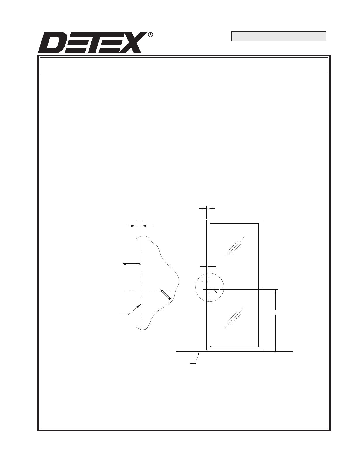
1. Mark a line 1" from the edge of the door (See Fig. 1).
2” NARROW STILE
GLASS DOOR
1”
1”
APPROXIMATE
8” LINE
FINISHED FLOOR
40”
Fig. 1
INS-101269 PAGE 1
Page 2
2. Block door shut. (Perform steps 3 through 8 inside door.)
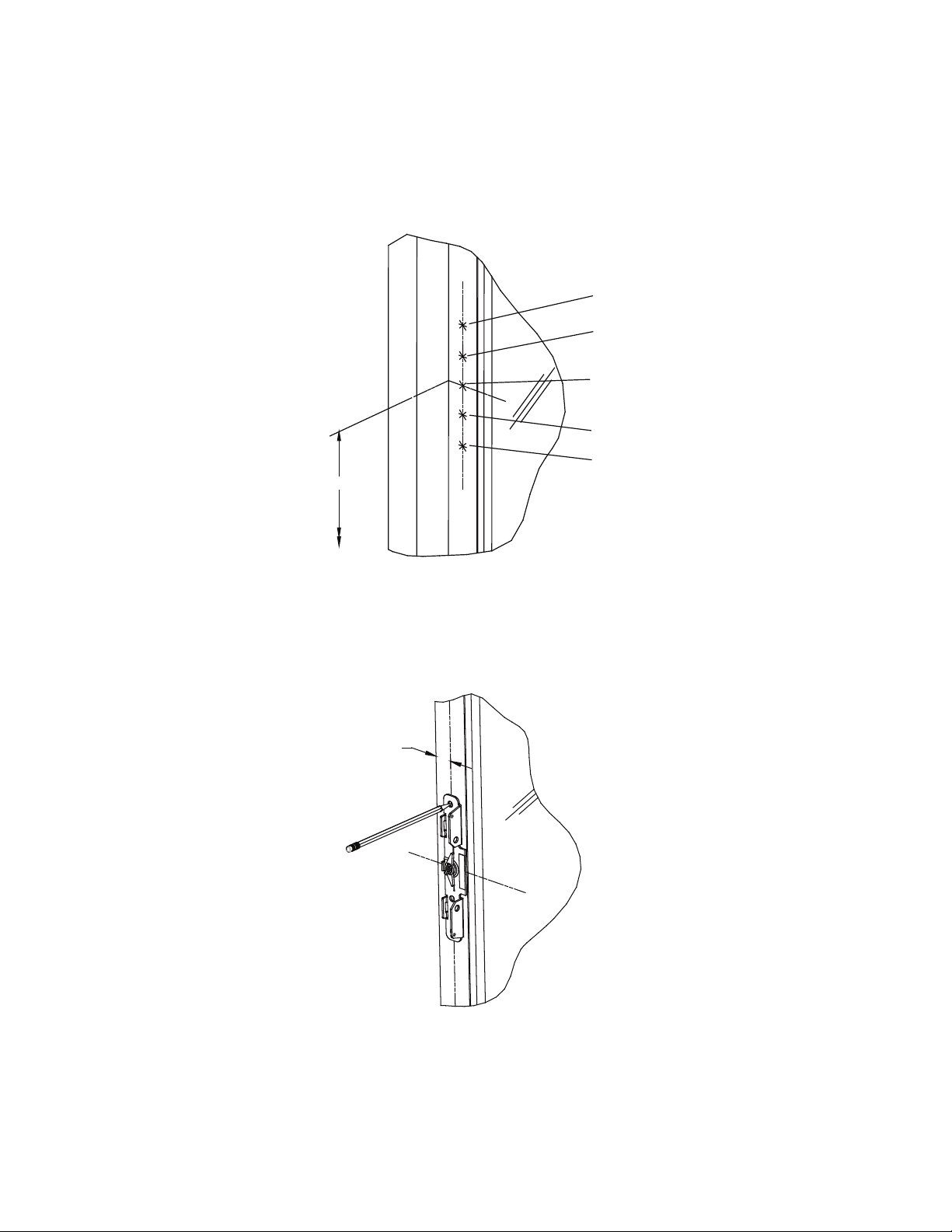
3. Detex recommends the device to be mounted 40" above the nished oor. Mark the
40" centerline of the device across the door and frame. (See Fig. 2)
a
e
d
e
a
40”
Fig. 2
4. Place back plate on door stile. Use the 1" line and center holes (a & e) on back plate.
Align cam center to mark "d" for proper height. (See Fig. 3)
1”
Fig. 3
5. Mark and center punch 5 holes "a" "d" & "e".
INS-101269 PAGE 2
Page 3
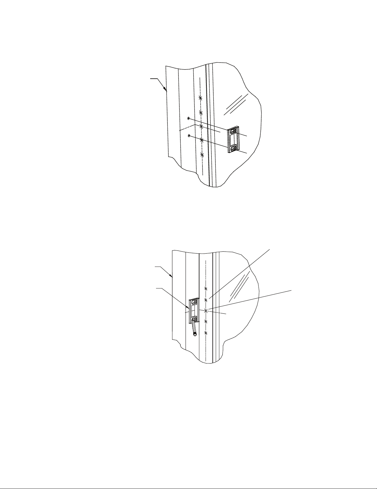
6. Slide the strike against the blocked door. (See Fig. 4)
DOOR FRAME
Fig. 4
7. Mark and center punch 2 strike holes. (See Fig. 5)
DOOR FRAME
CENTER MORTISE STRIKE
(RECOMMENDED 40” DISTANCE
FROM FINISHED FLOOR)
8. Drill one pilot hole "e" thru door (See Fig. 5).
e
d
Fig. 5
NOTE: DRILL STRAIGHT AND LEVEL
INS-101269 PAGE 3
Page 4
OUTSIDE DOOR FACE:
9. Place back plate on door (use as template).
10. Center the back plate on pilot hole "e" and align back plate vertically.
11. Mark the cam center "d". Mark and center punch the other hole "e".
12. Make a new mark 1/4" higher than the cam center (just marked). This will be the mark for
the 1 3/4" outside cylinder hole "f".
13. Drill a pilot hole through the door for "e" and "f".
NOTE: DRILL STRAIGHT AND LEVEL
14. Using a 1 3/4" hole saw, cut through outside door face at "f".
NOTE: USE EXTREME CAUTION WHEN DRILLING 1 3/4" HOLE.
TIGHT TOLERANCE, NO MARGIN FOR ERROR.
INSIDE DOOR FACE:
15. Drill 3/4" hole through inside door face at "d".
16. Using a 5/16" drill bit, enlarge the two holes "e" through door.
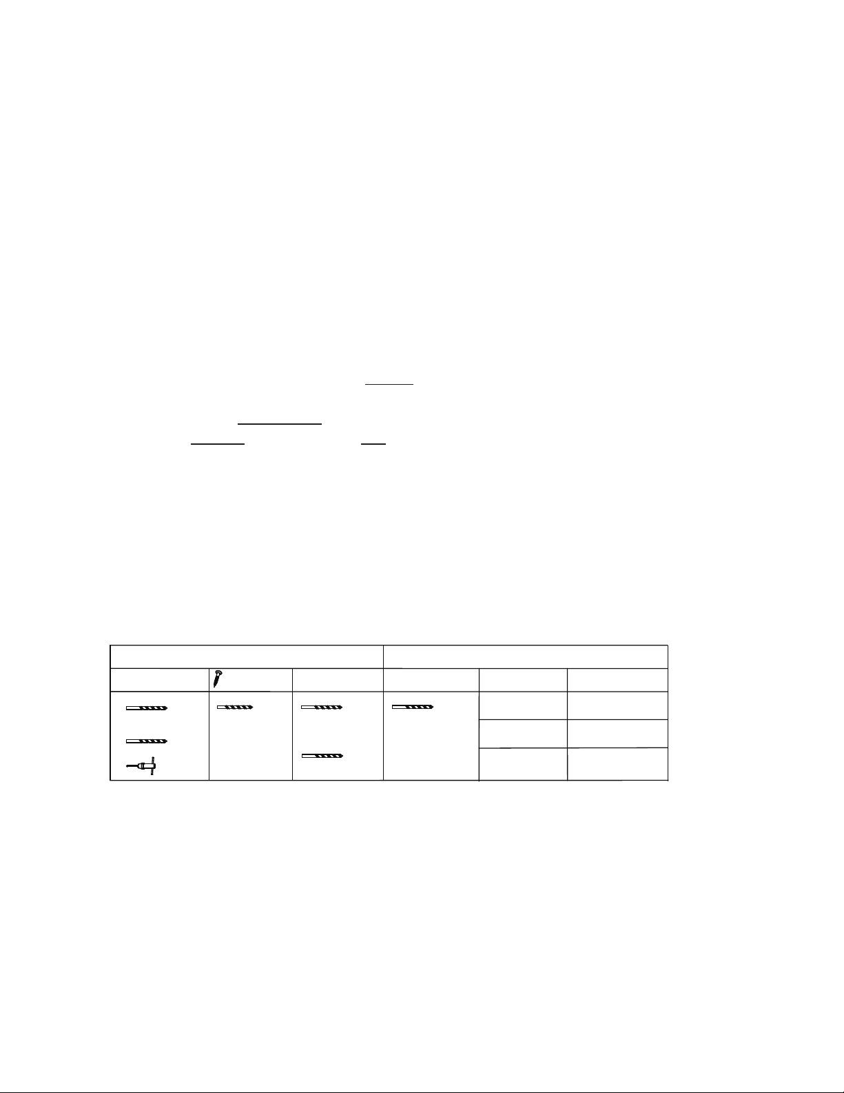
17. See Fig. T6. Drill back plate mounting holes "a" per chart. CAUTION: Holes "a" are
drilled inside only.
Backplate Mounting Holes “a”
1/4-20 Machine #14 Wood #14 Sheet 1/4-20 Machine Door Screw Length
Screw Screw Metal Screw Screws Thickness 1/4-20
# 7 3/16” # 7 5/16 1 3/8” 2”
OR
13/64
1/4-20
OR
13/64
Trim Holes “e”
1 3/4” 2 1/4”
2” or 2 1/4” * 3”
* Cut to length
Fig. T6
Go to Instructions P/N 101257 (03WS Installation Instructions)
Complete Page 2 "Preparing the Trim".
Skip Page 3
Complete Page 4 "Assembling the Outside Trim....."
Resume with Panic Hardware Instruction #15.
INS-101269 PAGE 4
 Loading...