

Page 1
104832 June 27, 2011
Detex Corporation, 302 Detex Drive, New Braunfels, Texas 78130-3045
(830)629-2900 / 1-800-729-3839 / Fax (830)620-6711
E-MAIL: [email protected] INTERNET: www.detex.com
INSTALLATION INSTRUCTIONS FOR
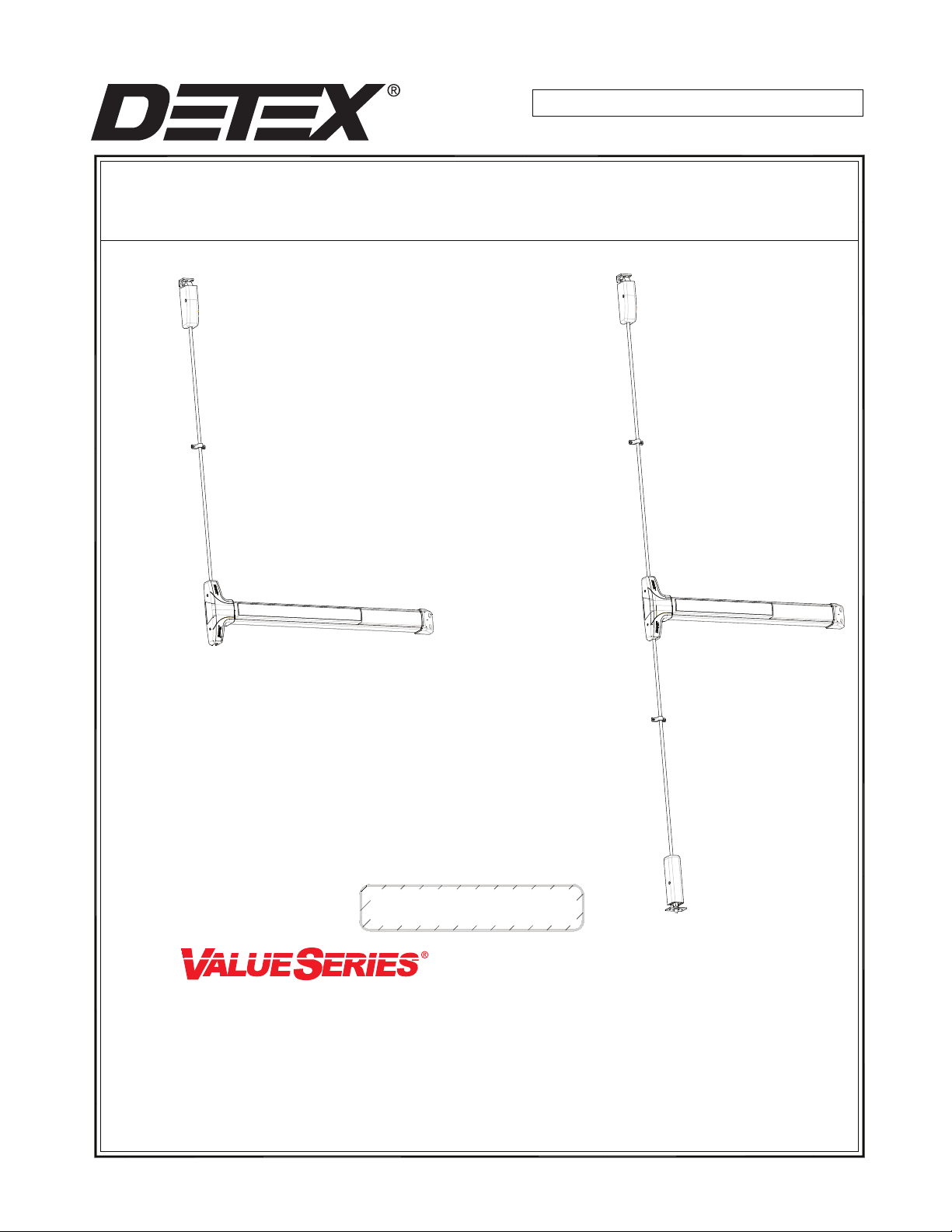
VALUE SERIES® SURFACE VERTICAL ROD V50/V51 SERIES AND FV50/FV51 SERIES
FV50 / V50 x EE
FV51 / V51 x EE
Delayed Egress
L9 = Less 9v Battery
SI = Status Indicator "ON"
U.S. PATENT NUMBERS:
6009732
6205825B1
6532777B2
INTERNATIONAL PATENT NUMBER:
PCT6009732
TRO - TOP ROD ONLY INSTALLATION
V51 and FV51 SERIES
TOP AND BOTTOM ROD
INSTALLATION
V50 and FV50 SERIES
* Narrow Stile "NS" option
Mortise cylinder not included with device.
Standard Yale type cam required.
Owner's Copy
SURFACE VERTICAL
ROD INSTALLATION
FOR SPECIAL LOCKING ARRANGEMENT:
THIS PRODUCT MUST BE CONNECTED INTO A FIRE ALARM SYSTEM PER NFPA CODE OR OTHER
REGULATIONS SO THAT, IN THE EVENT OF FIRE, THE TIME DELAY WILL BE BYPASSED. CONTACT
YOUR LOCAL CODE AUTHORITY TO VERIFY COMPLIANCE WITH FIRE AND BUILDING CODES.
THE DELAYED EGRESS DEVICE SHOULD BE ROUTINELY CHECKED FOR PROPER OPERATION AND
COMPLIANCE WITH FIRE AND BUILDING CODES
104832 Page 1
Page 2
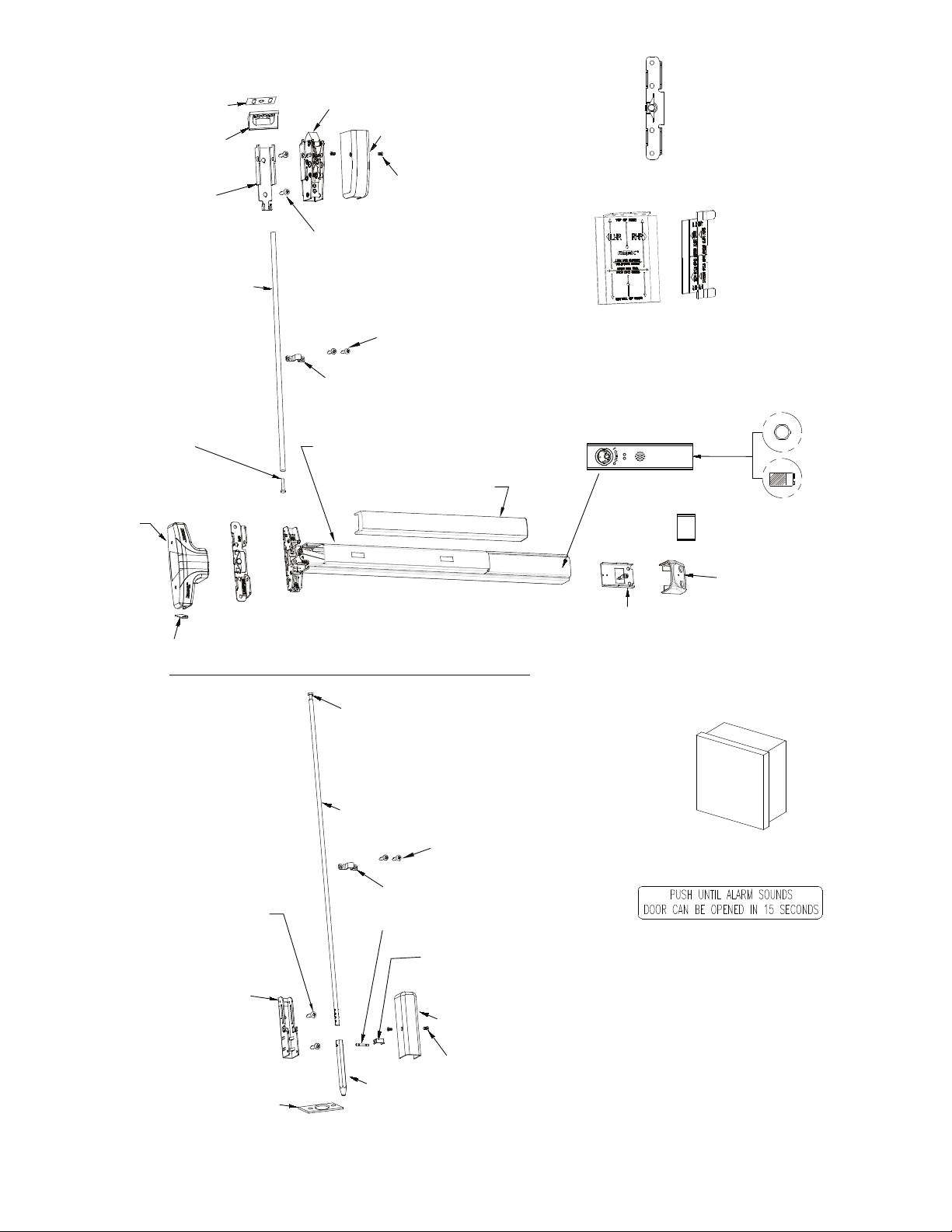
Strike Shim
P/N 101067
96 Strike
P/N 100330
Bracket is part of Top
Latch Assembly
7' P/N 104051-1
8' P/N 104051-2
10' P/N 103073-1
Top Rod
Top Latch Assembly
P/N 101464
Top Latch Cover
1/4 20
or
#14 Screws
#10 Screws
Rod Guide
P/N 103534
P/N 103545
8-32 Screws
Mounting plate
Subassembly
(BP-2)
P/N: 100696-1
or
(BP-8)
P/N: 100699
(FOUND IN MOUNTING PLATE/STRIKE TEMPLATE KIT)
LATCH/STRIKE
TEMPLATE
P/N 101511-1
(FOUND IN MOUNTING PLATE/STRIKE LOCATOR KIT)
LOCATING TOOLS USED WITH VALUE SERIES®
SURFACE VERTICAL DEVICES
(PAPER TEMPLATES ALSO INCLUDED - P/N 103569)
CENTERCASE MOUNTING
PLATE TEMPLATE
P/N 100720
1/4-20 Hex Bolt
7' & 8' P/N 101574-1
10' P/N 101574-2
Centercase Cover
P/N: 101805-3
Centercase Cover Cap V50
(for TRO unit only)
P/N 103547
PARTS BELOW ARE USED IN ADDITION TO
TRO PARTS SHOWN ABOVE WHEN
INSTALLING TOP & BOTTOM ROD DEVICE
1/4-20
or
#14 Screws
S & R Centercase Pushpad Assembly
P/N 105411-X
Pushpad Wrap
101810-X
101815-X
TRO - TOP ROD ONLY INSTALLATION
SOME FIRE RATED DOORS MAY USE TRO.
REFER TO DOOR MANUFACTURER.
FOR THESE APPLICATIONS,
POPPER INSTALLATION REQUIRED-
See Pg. 15, Fig. 16
1/4-20 Hex Bolt
P/N 101574-1
Bottom Rod
P/N 103544
Rod Guide
P/N 103534
Bolt/Rod Pin
P/N 103533
#10 Screws
SVR EE Fillerplate SubAssembly
P/N: 105031-X
NS Spacer (1 5/8)
P/N: 101825-1
Endcap
P/N 101822
Endcap Bracket
P/N 101844-1
Endcap Bracket w/ 9V battery holder
P/N 101844
Detex Power Supply Catalog No: 90-800
(80-800 Battery back-up power supply
available)
DETEX
Door Sign
P/N: ECL-395-X
Hex Nut
P/N: 100783
9V Battery
P/N: PP-5567
Bolt Retaining
Bracket
P/N 103537
Strike
P/N 103546
Pin Clip
P/N 103551
Bottom Bolt
P/N 103536
104832 Page 2
Bottom Cover
P/N 103652
8-32 Screws
See Optional Accessories For:
- Glass Bead Kit
- Sex Nuts
- Tamper Kit
- Key Stop Kit
* Notes: 1. Parts listed above will vary
according to product configuration.
See Optional Accessories page
Page 3
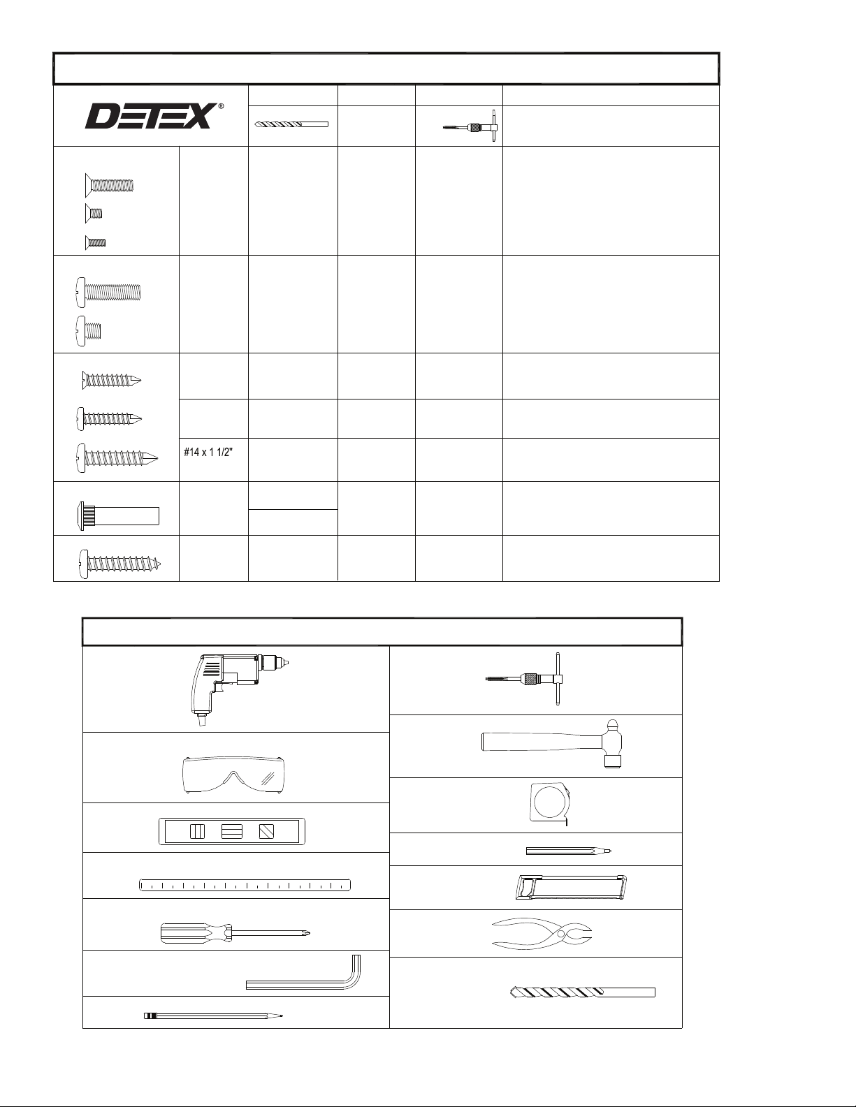
Fastener Table for Surface Vertical Rods
Machine Screw
Machine Screw
Self-drilling Screws
Screw, Wood
Flat Head
Pan Head
Sex Nut
10-24
8-32
6-32
1/4-20x1
1/4-20x1/4
#10 x 1"
PFH
#10 x 1"
PPH
PPH
#1/4-20
#14x1 1/4
Drill Bit
#25 or 9/64"
#7 or 13/64"
NOT
REQUIRED
NOT
REQUIRED
NOT
REQUIRED
9/32" Interior
Door Face
3/8" Exterior
Door Face
3/16"
Part No.
100112
100156-104
100162-106
100980
101621-5
103277-216
103276-41
103276-65
Catalog No.
SN1-X
103991
Tap Wrench
10-24 Tap
1/4-20 Tap
-----
-----
-----
-----
-----
-----
Comments
Use Either Machine Screws,
Sheet Metal Screws, or Sex Nuts
Used on Strike Center Mounting Hole
Used to attach top and bottom latch
covers
Used to attach centercase cover
Used on Strike, Mounting plate, Endcap,
Top and Bottom Latch Mounting Plates
Used to attach device centercase to
Mounting plate
Used on Strike Center Mounting Hole
Used on Rod Cover Brackets
Used on Strike, Mounting plate and Endcap
Used on Strike, Mounting plate and Endcap
Mounting Holes
Wood and Unreinforced Doors
and
Fire Rated Devices
Mounting Holes
Power Drill
Safety Glasses
Level
Straight Edge
Screw Drivers - Phillips, Flat
Hex Wrenches - 5/32" & .050"
Pencil
Tools Required
Tap Wrench
Hammer
Tape Measure
Center Punch
Hack Saw
Pliers
Masonry Bits - 1", 5/16", 3/16"
104832 Page 3
Page 4
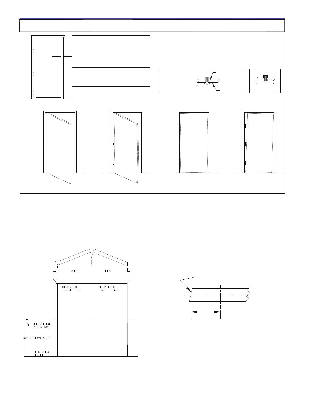
!!!CHECK BEFORE STARTING!!!
Doors and frames with walls having a structural thickness (metal skin
Wide Stile (Surface Strike)
Minimum door stile 3-1/2" (89 mm)
Template drawings provide door and frame
structural and dimensional specifications for
door and frame preparation.
plus reinforcement, or solid wood) to engage less than (3) full
screw threads, are considered unreinforced for hardware.
Unreinforced Doors: Use Sex Nuts and Bolts
Unreinforced Frames: Use Blind Rivet Nuts (see sketch)
Fasteners for unreinforced openings are not supplied by Detex.
Narrow Stile
Minimum door stile 2" (51mm)
* See Template T1000 for recommended reinforcement.
Reinforced door or
frame engages at
least (3) screw
threads.
Reinforcement
Door Skin
Blind Rivet Nut
X
X
X
Door Must Swing Freely Door Must Not be Warped Door Must Not Bind Door Must Not Sag
NOTE:
750mm MAXIMUM DOOR WIDTH OPENING FOR EUROPE FOR 36" DEVICE
1000mm MAXIMUM DOOR WIDTH OPENING FOR EUROPE FOR 48" DEVICE
THE SAFETY FEATURES OF THIS PRODUCT ARE ESSENTIAL TO IT'S COMPLIANCE WITH EN 1125.
NO MODIFICATION OF ANY KIND, OTHER THAN THOSE DESCRIBED IN THESE INSTRUCTIONS ARE PERMITTED.
WHEN PLACING EXIT DEVICES ON EXISTING DOORS, DETEX OFFERS SVR REINFORCEMENT KIT #101063
INSTALLATION
NOTE: LOCAL CODES MAY REQUIRE THROUGH BOLTING. SEX NUTS ARE NOT INCLUDED WITH THIS DEVICE. SEX NUTS CAN BE PURCHASED
SEPARATELY.
Detex provides optional kits for Value Series, see Appendix C.
TO STRENGTHEN THE TOP & BOTTOM BOLT
X
Lock Backset - The horizontal distance from the door edge
centerlinemeasured at the door thickness, to the centerlone of the lock
hub or cylinder.
104832 Page 4
1/8" in 2"
Typical Bevel
Backset
Page 5
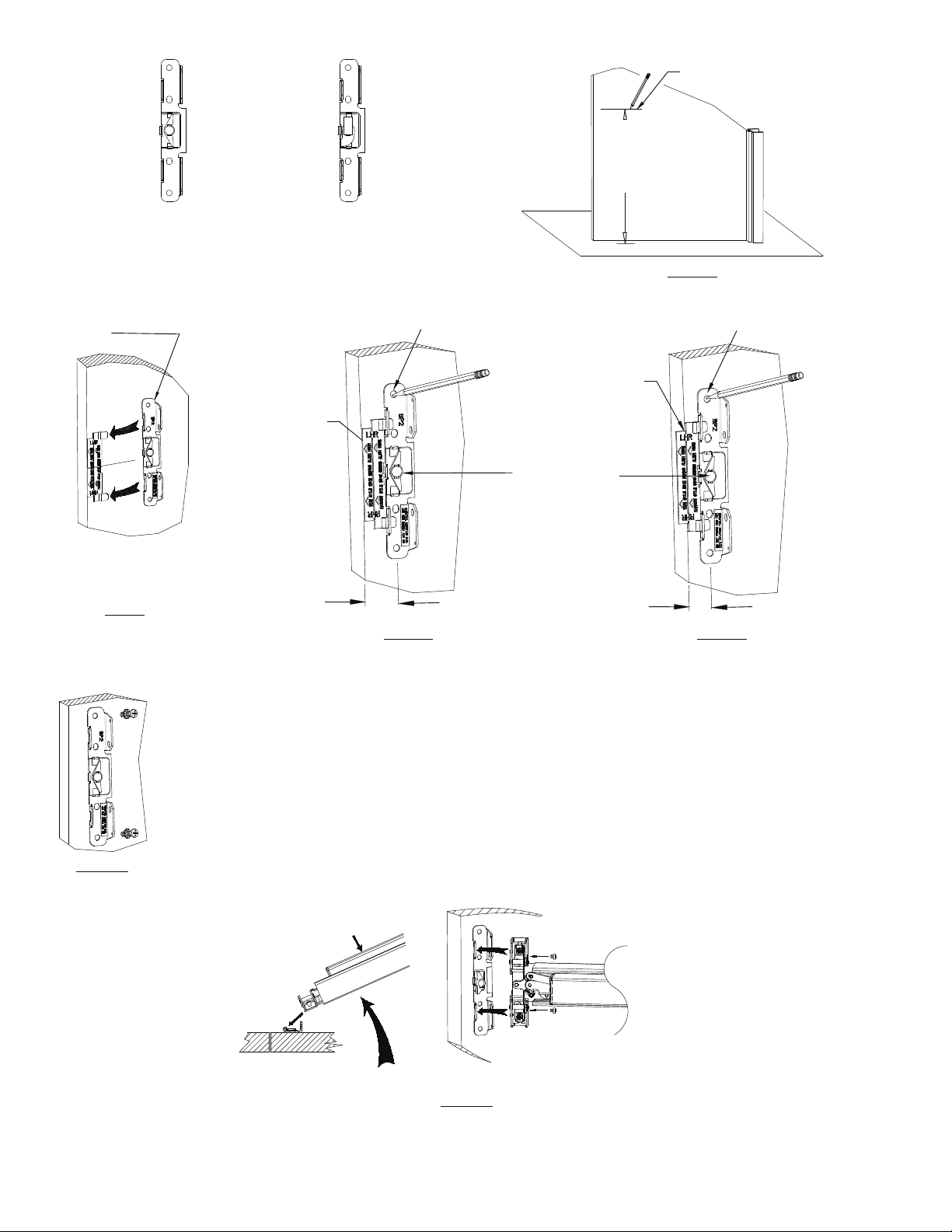
Approx. 6 inches
BP-2
P/N 100696-1
MOUNTING PLATE FOR
USE WITH LEVER TRIM
Slide centercase mounting
plate in place on centercase
locator
NOTE:
Centercase mounting plate
& locator packed in carton
next to device
FIG. 2
MOUNTING PLATE FOR
Align EDGE
of locator
with edge
of door
1-1/2" to edge
of door
(* 2" with tab)
BP-8
P/N 100699
USE WITH 03 TRIM
Mark 2 (A) holes for mounting
screws (1 top & 1 bottom)
(A)
(D)
(A)
FIG. 3A
WIDE STILE INSTALLATION
Typical Installation Min. Stile 3 1/2"
-RecommendedMark centerline for
unit 40 inches from
finished Floor
Align INSIDE
CORNER of
locator with
edge of door
If trim is used, peel
back label from cam,
mark (D) center hole
for tailpiece, replace
label
FIG. 1
Mark 2 (A) holes for mounting
screws (1 top & 1 bottom)
(A)
(D)
(A)
1-1/16" to
NARROW STILE INSTALLATION (NS)
FIG. 3B
Aluminum Door Min. Stile 2"
edge of door
FIG. 3C
Drill holes.
Fasten using lockwashers and
screws provided. Use #7 for 1/4-20
machine screw or use #14 self drilling
screws. For sex nuts drill 3/8" holes.
(see fastener table)
Depress pushpad, install device
into mounting plate slots,
rotate toward door
NOTES:
1. IF OUTSIDE TRIM IS USED, REFER TO OUTSIDE TRIM
INSTRUCTIONS NOW.
2. Plastic locators are provided and shown in instructions.
Paper templates are also provided with vertical and horizontal centering.
3. Plastic locators are provided with an extra 1/2" flap to allow better
centering of the device on the stile or can be used when i
nstalling 1/2"
Astragal to give equal backset from the door edge.
Fasten rim device
Install device
FIG. 3D
to mounting plate
104832 Page 5
Page 6
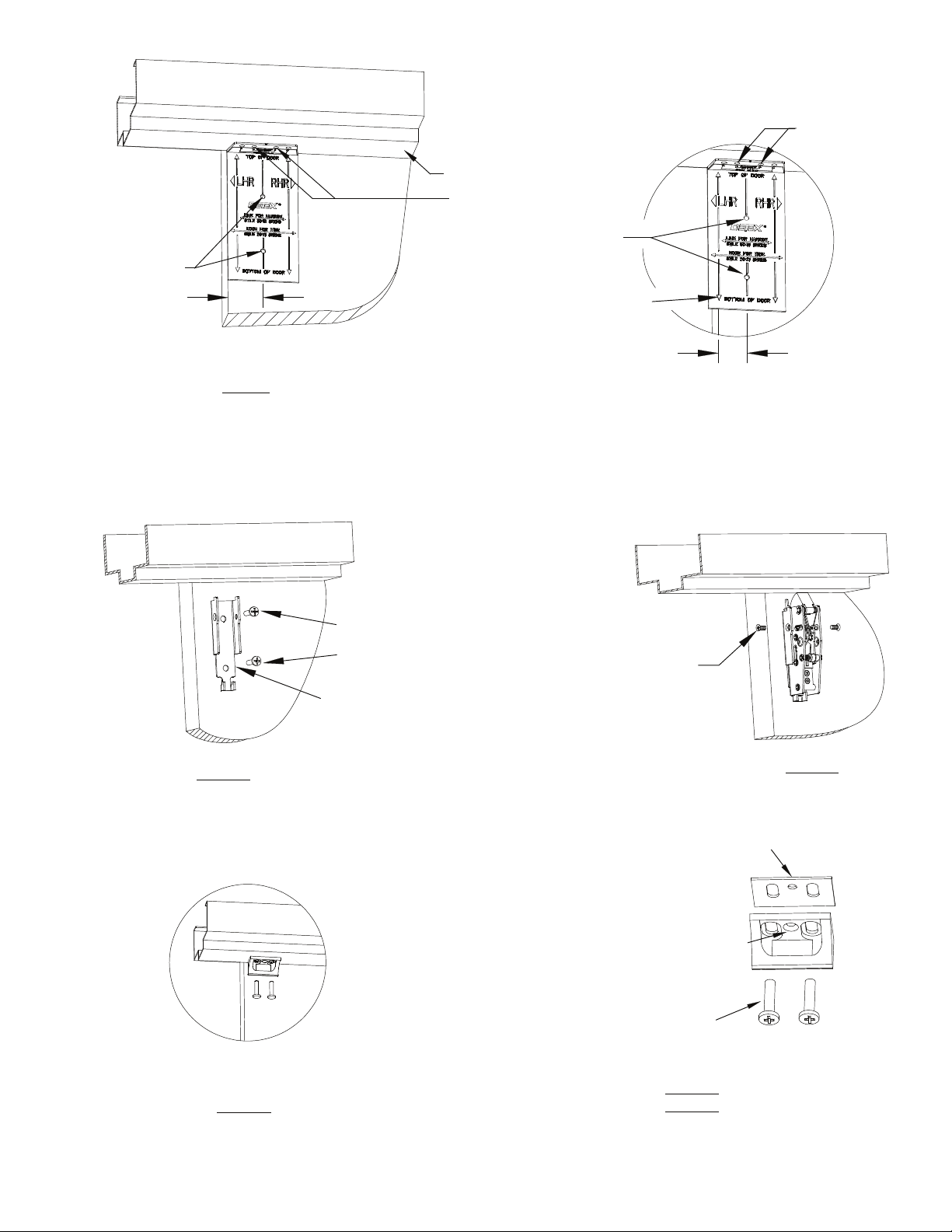
WIDE STILE
Align latch/strike
locator with edge
of door
Mark for top latch
1-1/2" from
edge of door
(* 2" with tab)
Left Hand Reverse shown
FIG. 4
FIG. 5A
Frame header
Mark for 96 strike
Mark for top latch
NARROW STILE (NS)
Align arrow line with edge of
door and frame header
Drill holes,
#7 for 1/4-20 machine screws,
and fasten with 1/4-20x1 PPH
machine screws or #14 self drilling
screws. For sex nuts drill 3/8" holes.
(see fastener table)
NOTE: Do Not use lock washer
Install top latch bracket
NOTE: Top latch bracket, latch assembly
and cover are shipped as a unit.
Disassemble to obtain the respective parts
for installation
Mark for 96
strike
1-1/16" from
edge of door
10-32 x 5/16 PFH
Undercut machine screws
FIG. 5B
Drill holes,
#7 for 1/4-20 machine screws,
and fasten with 1/4-20x1 PPH machine screws
or #14 self drilling screws. (see fastener table)
96 Strike
(Used for Narrow (NS)
AND Wide Stile installations)
FIG. 5C
SEE DETAIL
104832 Page 6
Use shim if needed
#10 Flat head undercut screw
added AFTER final adjustment
(See Pg. 11
Adjustment/Troubleshooting
Note #4)
1/4-20 PPH machine screws
or #14 self drilling screws
FIG. 5C
DETAIL
96 Strike
Page 7
NOTE: IF TRO DEVICE, SKIP THIS PAGE AND CONTINUE WITH INSTALLATION
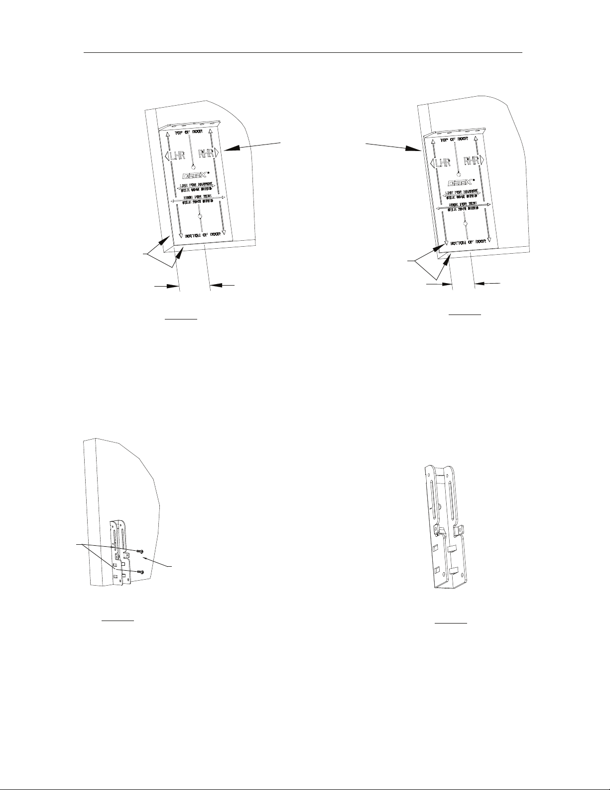
WIDE STILE
Locator placement
Align locator EDGE with
door edge and locator
bottom with bottom of door
or top of threshold if threshold
overlaps bottom edge of door.
FIG. 6A
Same locator used
for top latch
1-1/2" from
edge of door
(* 2" with tab)
Align locator ARROWS
with door edge and
bottom of locator with
bottom of door, or top of
threshold if threshold
overlaps bottom edge of
door
NARROW STILE (NS)
Locator placement
1-1/16" from
edge of door
FIG. 6B
Bottom
holes
FIG. 7A
Drill holes for bottom bolt bracket (see fastener
table)
NOTE: IF OPTIONAL BOTTOM BOLT GUARD
WILL BE USED, AN ADDITIONAL MOUNTING
BRACKET IS REQUIRED. SEE BOTTOM BOLT
GUARD INSTALLATION INSTRUCTIONS.
Install bottom bolt bracket with mounting
screws provided. Use #7 drill for 1/4-20
machine screw or #14 self drilling screw.
For sex nuts drill 3/8" holes.
(see Fig. 7B)
NOTE: BOTTOM BRACKET IS
NON-HANDED AND MAY BE USED
FOR RHR AND LHR APPLICATIONS
FIG. 7B
104832 Page 7
Page 8
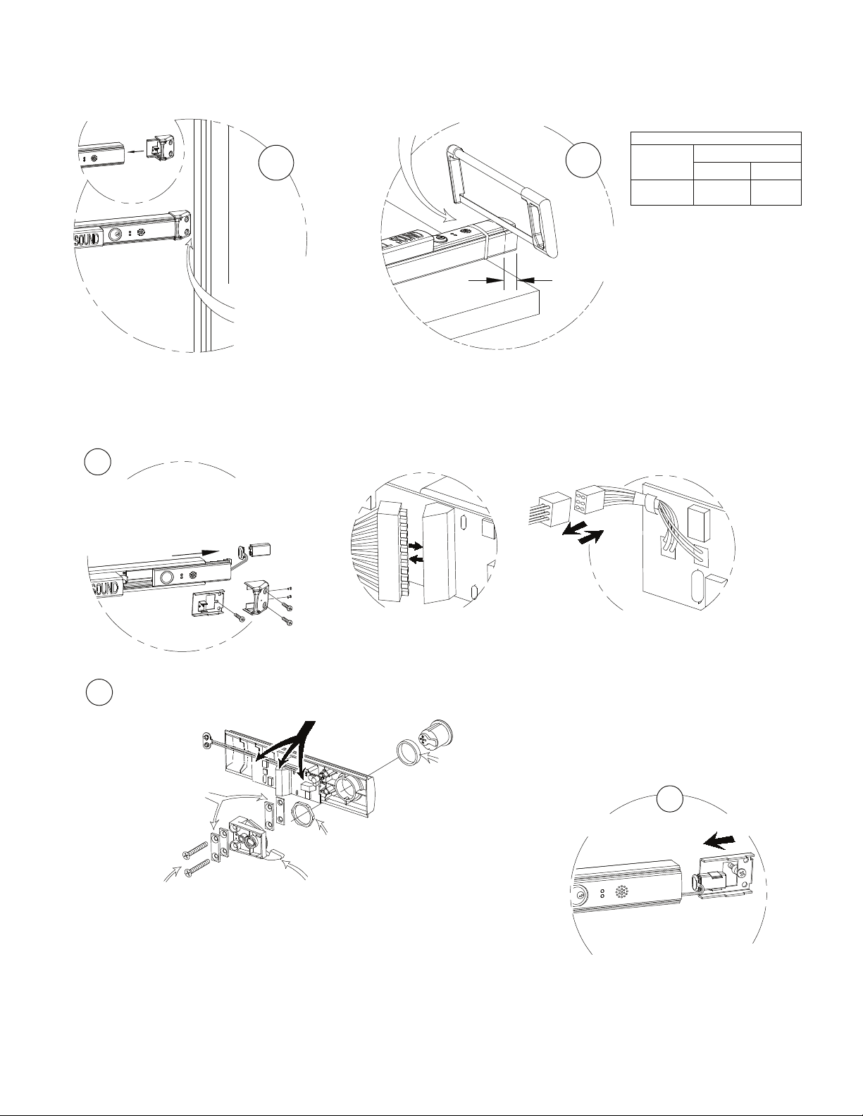
CHECKING FOR DEVICE CLEARANCE
Slide endcap assembly
onto extrusion
(Cut-Off procedure if required)
1
CAUTION:
Check device and door
frame clearance. If no
cut-off needed, proceed
to MORTISE CYLINDER
INSTALLATION
MORTISE CYLINDER INSTALLATION
1. See "EE ELECTRICAL OPTIONS" before reinstalling filler plate.
2. Be careful when installing fillerplate assembly not to damage wires.
1
Remove endcap, endcap bracket & fillerplate
subassembly.
Disconnect 12 pin connector, 6 pin connector
and battery
Secure with tape
Protect wires
during cutting
PRECAUTIONARY NOTE:
2
Cut fillerplate and
extrusion to desired
length
L
Max Cut-Off
Type
Electrified
Model
Length (L)
36" Unit
cannot be
cut down
48" Unit
6 in
2
INSTALLING MORTISE CYLINDER
NOTE:
(1) Move placement of
spacers to match length
of cylinder used to allow
smooth rotation of cam.
2) All cylinder spacers
must be used, either
on top or bottom
CAUTION:
Tighten with hand tools only.
Do not overtighten.
View A
12 Pin Connection
(note: board layout may differ slightly from layout shown)
See View A, B, & C above
Install mortise cylinder
with hex nut provided
Dogging lever should be in "ON"
(CCW) position before sliding
back into extrusion
Use optional cylinder collar
(Detex p/n: ECL-1595)
installing 7-pin
mortise cylinder
when
View B
6 Pin Connector
3
RE-INSTALL FILLERPLATE
Re-connect in the following order:
1) Battery,
2) 12 pin connector (view A),
3) 6 pin connector (view B).
Install fillerplate subassembly
& endcap bracket.
104832 Page 8
Page 9
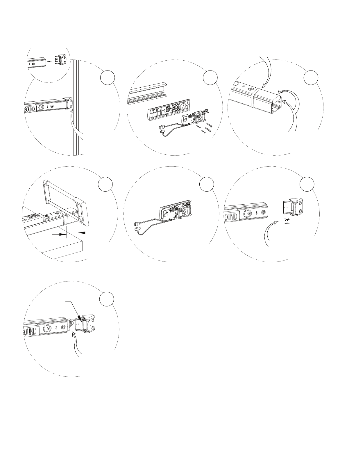
Slide endcap assembly
onto extrusion
Procedures for Additional Cut Down Lengths
Caution Required-Special Handling
Secure with tape
1
CAUTION:
Check for device and
door frame clearance.
4
L
Cut fillerplate
and extrusion to
desired length
2
REMOVE electronics
prior to cut down
5
Reassemble electronics
after cutting.
Electronics may extend
beyond edge of cut fillerplate.
3
Align fillerplate FLUSH
to extrusion
prior to cut down
6
REMOVE battery clip
for CUT-OFF lengths
larger than 2"
Battery
7
Place battery in endcap.
Battery should not contact
circuit board.
104832 Page 9
Page 10
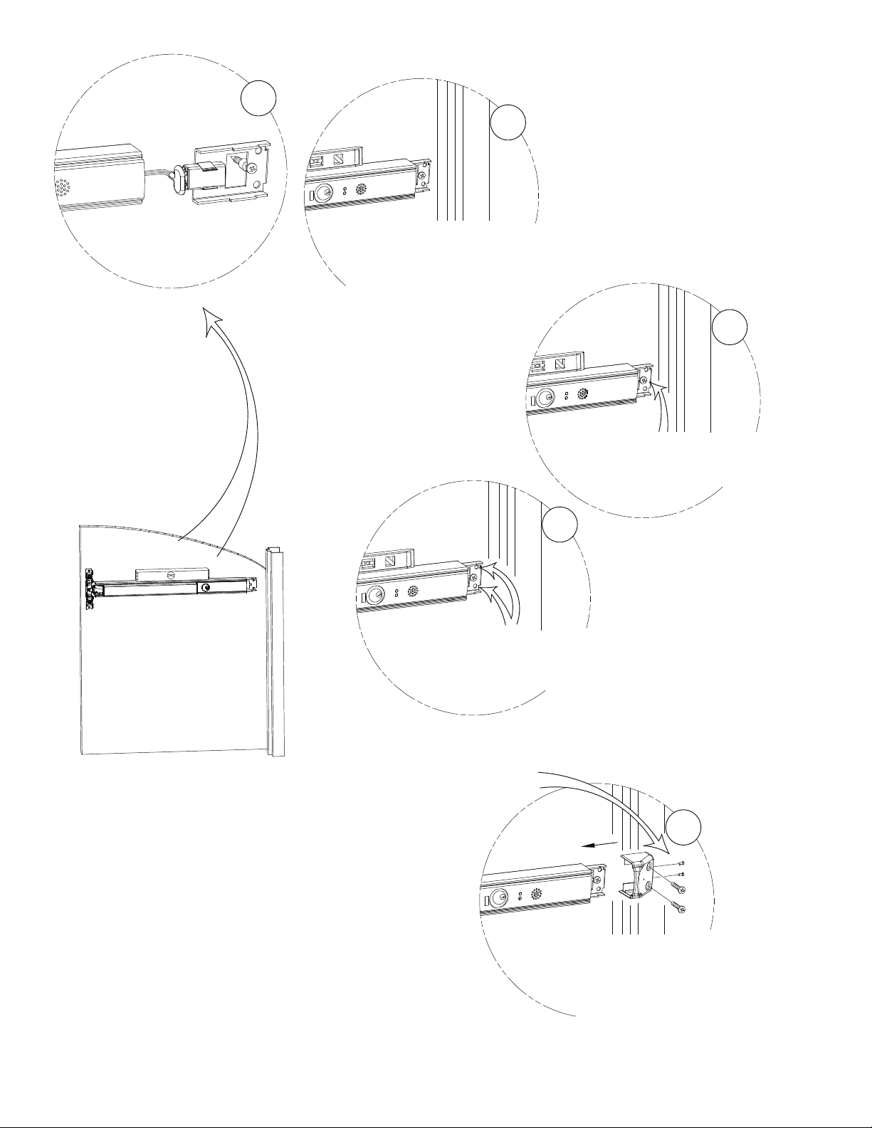
1
2
Slide fillerplate & endcap bracket into
extrusion & level pushpad assembly.
Note: Endcap Bracket must
bottom-out on extrusion. DO NOT
REMOVE NYLON SPACER ON
BACK OF BRACKET!
3
With pushpad assembly level,
secure the endcap bracket to door
by tightening the factory installed
self-drilling screw.
4
For 1/4-20 machine screws drill #7 holes.
For #14 self-drilling screws no pilot holes
necessary. For sex nuts drill 3/8" holes.
See HARDWIRE TRANSFER OPTIONS
IMPORTANT:
Install (2) 6-32 FH Screws
for added security
5
104832 Page 10
Slide and mount endcap
to endcap bracket with two
1/4-20x1" PPH machine screws
or #14 self-drilling screws.
DO NOT OVERTIGHTEN
Page 11
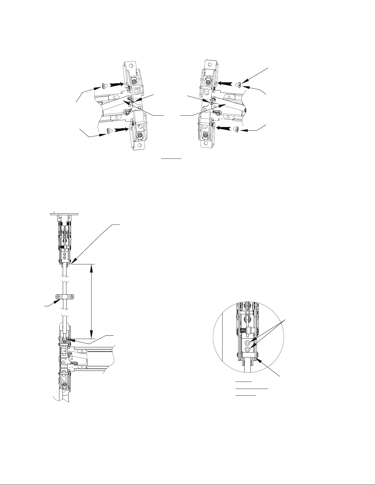
Right Hand Reverse (RHR)
NOTE: If removed, be sure
to replace screws after
adjustment.
These screws MUST be
used.
NOTE:
If link is not in uppermost position on the centerlift, carefully remove "E" clips and reposition link
on top pin of the centerlift and replace "E" clips. (An additional "E" clip is provided on opposite link pin.)
Verify carriage moves up and down smoothly when pushpad is depressed and released.
CORRECT HANDING OF DEVICE
NOTE: LINK SHOULD ALWAYS BE IN TOP POSITION
Left Hand Reverse (LHR)
NOTE HANDING
INDICATOR ON
CENTER LIFT
LINK
FIG. 8A
1/4 20 x 1/4"
Screws
P/N 101621-5
NOTE: If removed, be sure
to replace screws after
adjustment.
These screws MUST be
used.
Rod
Guide
Bottom edge of
top latch
1. Top rod may require cutting if centerline of
device is over 40" from finished floor, or if a
non-standard frame is used.
2. To determine rod length: Undog device
and measure the distance from the bottom
edge of the top latch bracket to the top of the
rod carriage. Add 1 3/4" for the rod length.
slot in
carriage
FIG. 9
TOP LATCH
DETAIL
Insert top rod into top latch
until it stops. Tighten
setscrews FIRMLY
In normal latched
position, rod
connector block
must rest on
plastic bumper
104832 Page 11
Page 12
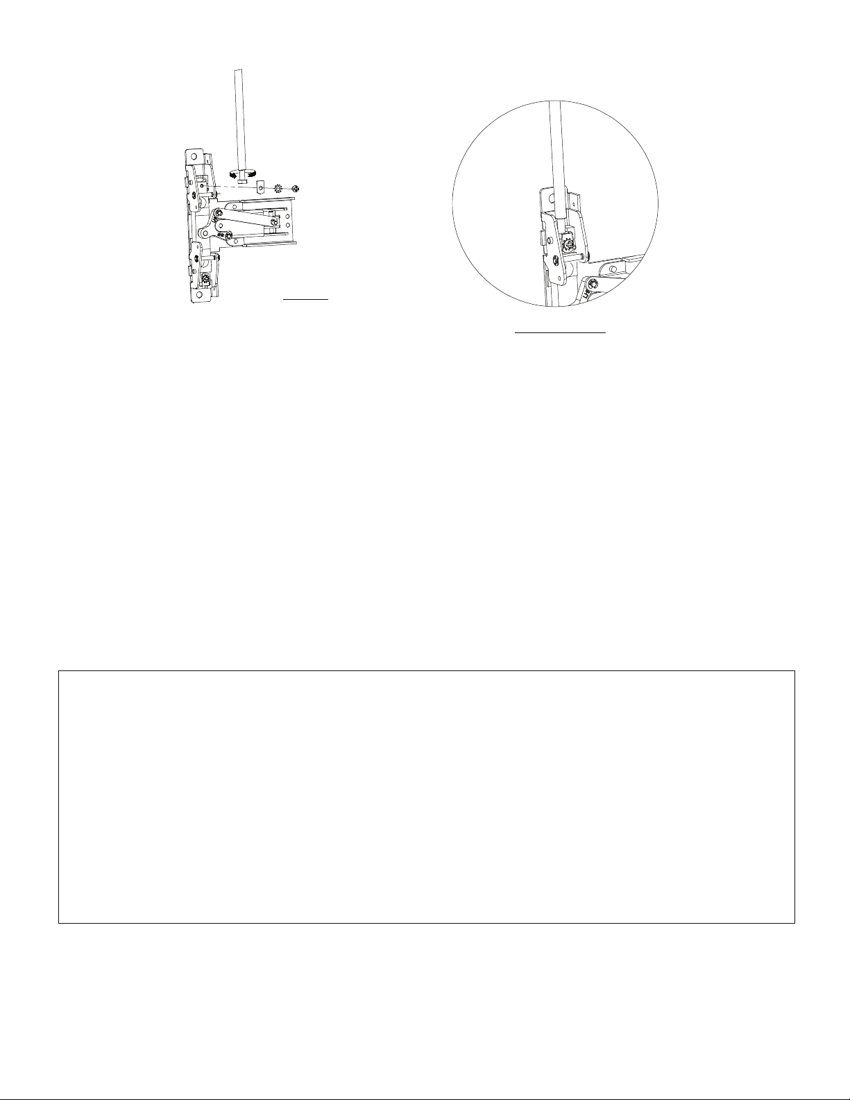
TOP ROD INSTALLATION (CONT.)
Verify top latch bolt is in
fully extended position.
Rotate bolt for rod height
adjustment. Head of bolt
should drop freely into slot
in carriage.
Lock Bolt head
firmly in place in
Carriage with plate,
starwasher and screw.
(As shown in detail)
FIG. 10
TOP ROD ONLY (TRO)
ADJUSTMENT / TROUBLESHOOTING
TOP LATCH TESTING AND ADJUSTMENT
1. Close the door. The holdback lever should engage the backside of the strike, allowing the latchbolt to extend. The
device should latch securely and latchbolt should fully project into the strike cavity.
2. Press the pushpad. The latchbolt should retract fully and smoothly from the strike as the door opens.
3. Release the pushpad. The latchbolt should remain retracte
4. Once the latchbolt operation has been evaluated, the strike should be checked and adjusted to allow the door to
be held snug to the frame but allow free movement of the latchbolt during normal operation. When the appropriate
position has been set. A third hole should be marked, drilled and tapped for a #10 machine or use a #10 self drilling screw.
Lock the strike in posi
NOTE: For centerline heights significantly higher or lower than the recommended 40", it may be necessary to use shorter or
longer adjustment hexbolts in the rods to effect appropriate adjustment. For some door heights it maybe necessary to cut the
rod. Be sure to cut the un-threaded end. If this is done, we recommend rod covers be used to prevent exposed bolt
TROUBLESHOOTING
tion with this third screw. (See Fig. 5C)
d until the door is closed.
FIG. 10 - Detail
threads.
1. Latchbolt does not completely relatch when closing the door
Loosen the strike screws and adjust the strike to allow the latchbolt to completely extend into the strike.
Tighten the screws and add the third center screw to lock the strike in place.
2. Latchbolt fails to retract when pushpad is pushed
Check centercase assembly and verify that the link is attached to th
or shorten top rod by rotating bolt. Relock bolt into carriage.
3. Latchbolt is slow or does not completely extend when door closes.
Check rod adjustment (Fig 10).
Check centercase, verify that the 1/4-20 x 1/4" screws have been installed (See Fig. 8A).
e TOP post of the centerlift assembly (see Fig. 8A),
104832 Page 12
Page 13
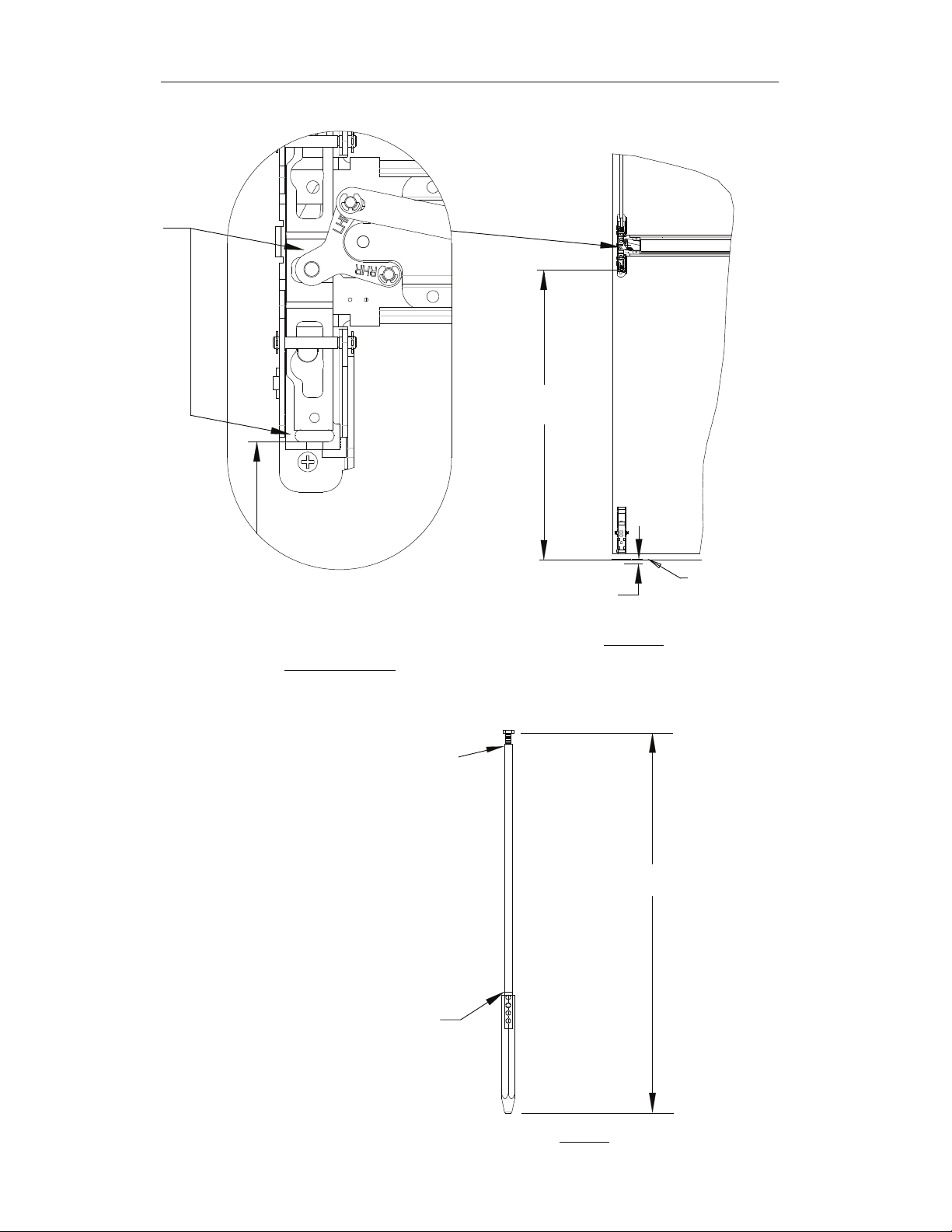
NOTE position
NOTE: IF TRO DEVICE, SKIP THIS PAGE AND CONTINUE TO PAGE 15
XX"
( Approx. 37 3/4"
Example)
To establish bottom rod length,
measure the distance from the slot
in the carriage to the floor or
threshold (XX") and add 5/8".
FIG. 10B - Detail
Thread 1/4-20 X 1"
hexbolt into rod a
MINIMUM of 1/2"
Insert rod into bottom bolt.
Align holes in rod and bolt that will result in
overall length closest to dimension needed.
Adjust threaded hexbolt at opposite end of
rod for fine adjustment of length.
Mark location on rod where it meets the bolt
and/or tape bolt in position.
5/8" BOLT
ENGAGEMENT
FIG. 10B
XX + 5/8" Example
Finished
Floor
104832 Page 13
FIG. 11
Page 14
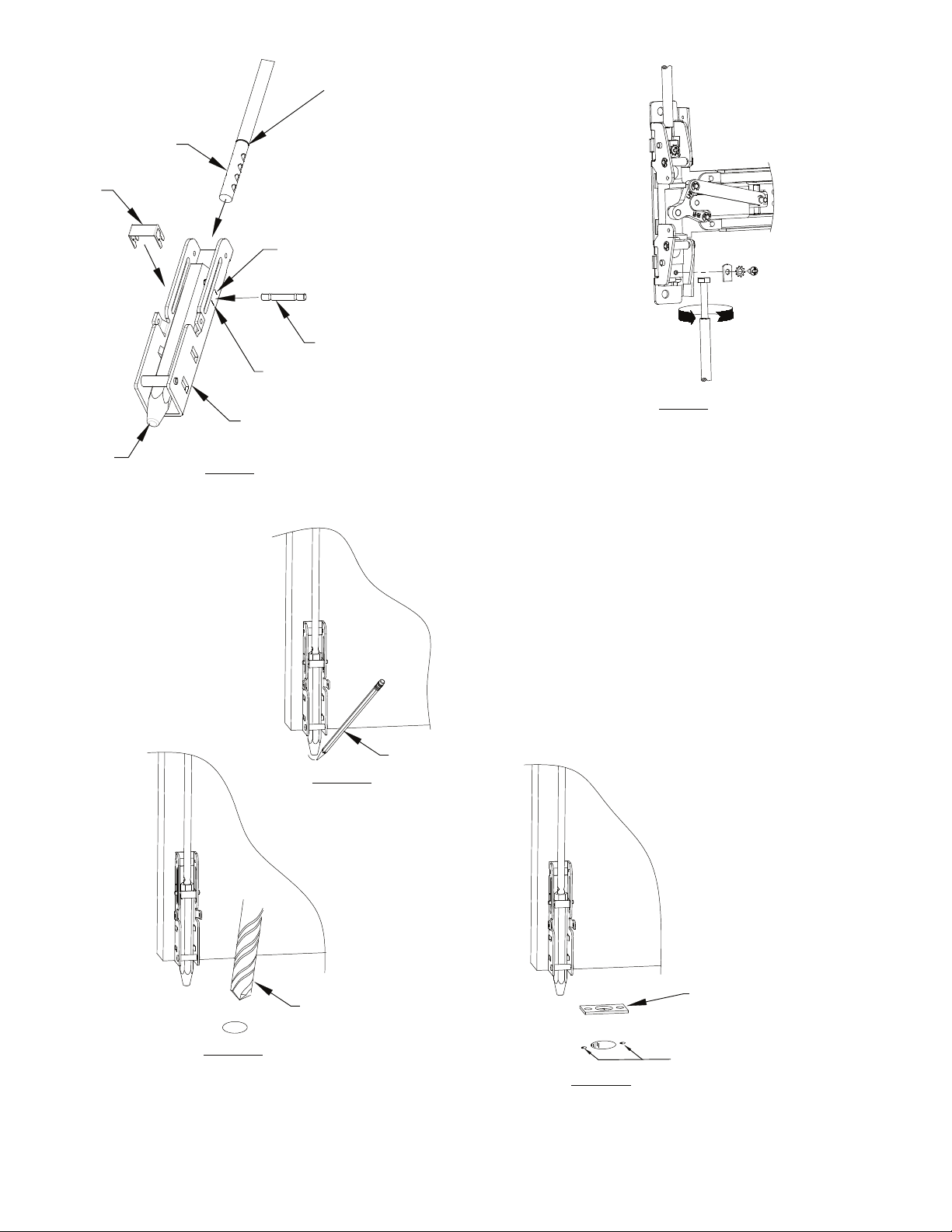
CLIP
ROD
Place bottom bolt and rod
assembly into bottom bracket. Slide
the pin through the slot of the
bracket through the bolt and rod
assembly. Insert pin clip. Use
1/4 x 20 bolt at top of rod to obtain
final adjustment. When properly
adjusted, pin will be located at or
near the index mark on the bracket.
BOLT
FIG. 12
INDEX MARK FOR 3/4" FROM FLOOR TO BOTTOM
OF DOON (UNDERCUT) & THRESHOLD
PIN
INDEX MARK FOR 1/8"
UNDERCUT
BRACKET
Lock bolt head
firmly in place
in carriage with
plate, starwasher
and screw
Rotate bolt for minor
rod height adjustment.
FIG. 13
FIG. 14B
FIG. 14A
Drill 1" hole for
strike (minimum
depth - 3/4")
With Door closed
use tip of Bolt to
mark location
for Strike
104832 Page 14
FIG. 14C
Attach strike (P/N 103546)
to floor or threshold
Drill holes for strike mounting screws
and secure strike with screws.
Drill 3/16" hole for plastic anchor.
Drill 5/16" hole for metal anchor.
Page 15
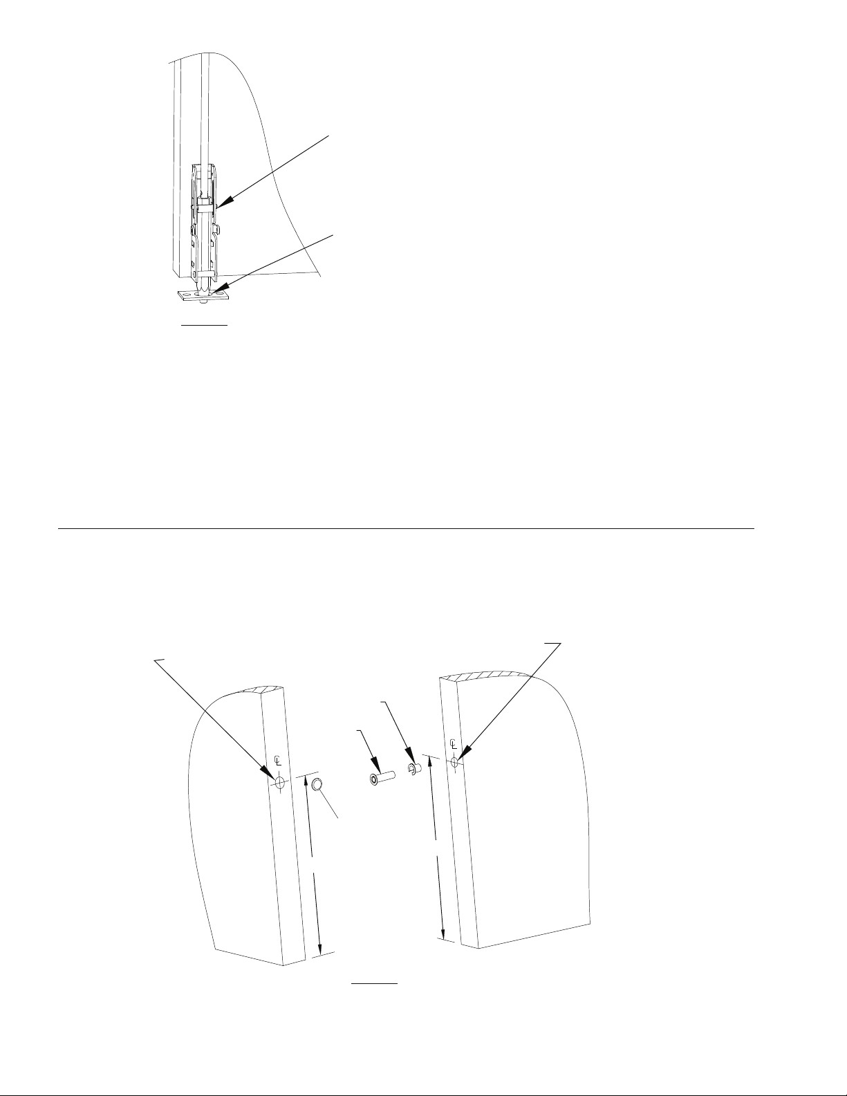
If additional length is required,
remove clip and link pin, move bolt
down and reinsert pin in
next lower hole. Insert clip on pin.
Adjust Bolt for approximately 1/16"
clearance between end of bolt and
surface of strike when retracted.
Open and close door to be sure bolt
does not hit high areas of floor.
Re-adjust if necessary. Confirm that
FIG. 15
BOTTOM LATCH Testing and Adjustment
Testing
1. Close the door; bolt should drop into the strike as the door moves into the fully closed position.
2. Press the pushpad and open the door. The bottom latch bolt should retract out of the strike
and clear the strike by 1/16" to 1/8". Vertical travel of the bolt should be 3/4".
3. Release
Adjustment
1. If bottom bolt drags the floor or hits edge of strike:
Loosen bolt retainer in the carriage assembly and pull bolt from carriage. Screw bolt onto bottom rod one or
two turns and return it to the carriage. Test door to assure clearance and secure bolt in carriage by tightening bolt
retaining plate.
the pushpad; bolt should remain retracted until the door is closed.
the bolt drops freely and does not
bind when latch is released
FIRE RATED TOP ROD ONLY (TRO) DOORS
A door locking popper is required when a fire door utilizes a top latching mechanism only (TRO). The popper is designed to
project a spring loaded bolt into the adjacent frame or door in the event of fire. Detex recommends
installing the popper in the edge of the door 12" above the threshold or finished floor. Holes for the popper
and plug must be aligned with each other.
9/16" Dia. Min.
3/4" Dia. Min.
1-1/4" Deep min.
Retaining Clip
Popper
Cap Plug
12"
1-5/8" Deep min.
12"
FIG. 16
NOTE: Door/Frame reinforcement is required where popper and cap plug are to be installed.
104832 Page 15
Page 16
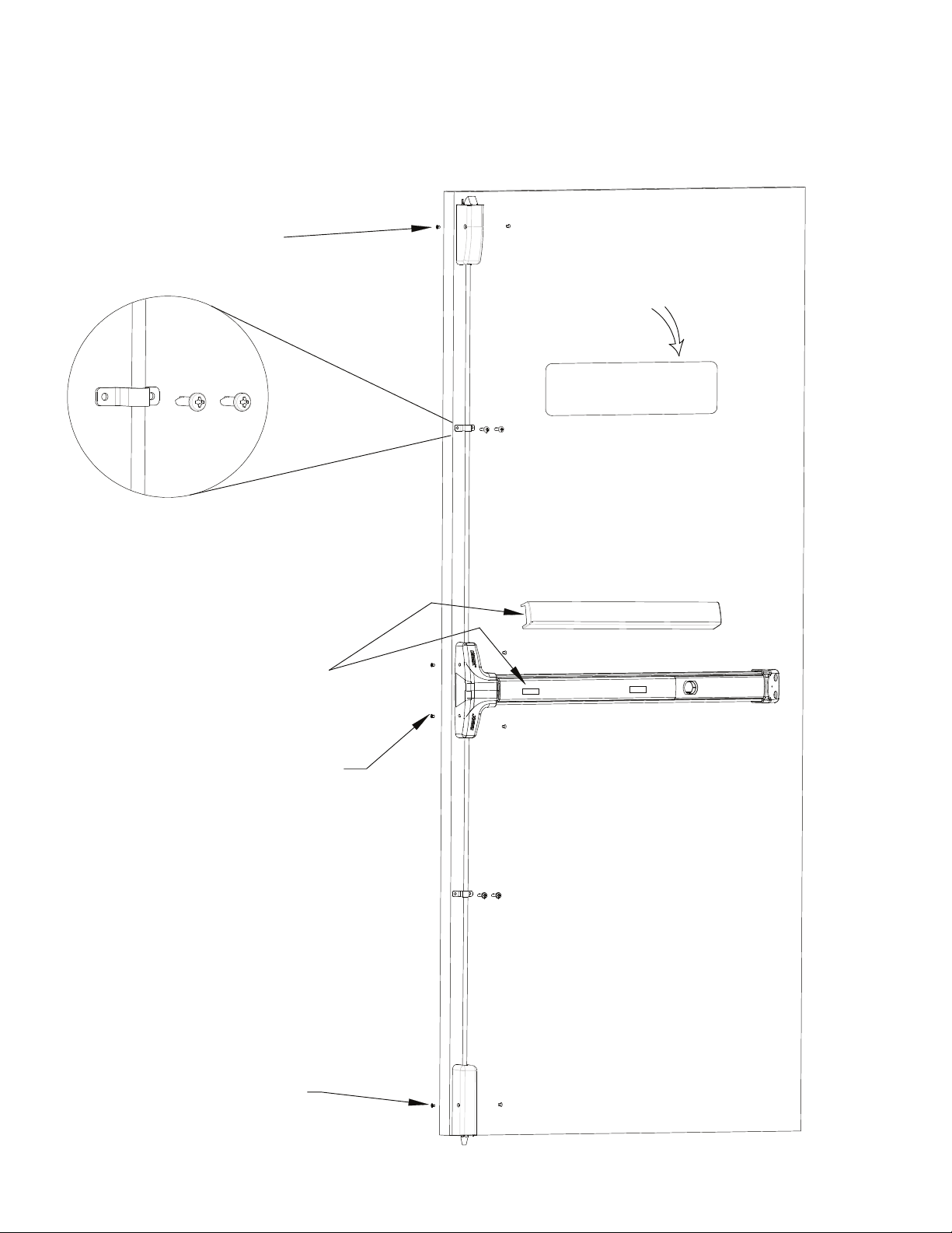
STANDARD SURFACE VERTICAL INSTALLATION
1. If metal bottom bolt guard is to be used, do not attach the plastic bottom latch cover (refer to bottom
bolt guard installation instructions.)
2. If rod covers are to be used, do not install rod guides (refer to rod cover installation instructions).
Top latch cover attached with
8-32 x 1/4" PFH screws
Place ECL-395-X
sign on door
Space 1 rod guide equidistant between
centercase and latch assemblies
(7 foot and 8 foot doors). Use 2 rod
guides spaced evenly on the top rod
of 10 foot doors.
Attach with 10-32 x 1 PPH machine
screws or # 10 self drilling screws
Remove tape
backing, Install
Pushpad Wrap
Centercase cover attached with 6-32 x
1/4" PFH screws
Bottom bolt cover attached with
8-32 x 1/4" PFH screws
104832 Page 16
Page 17
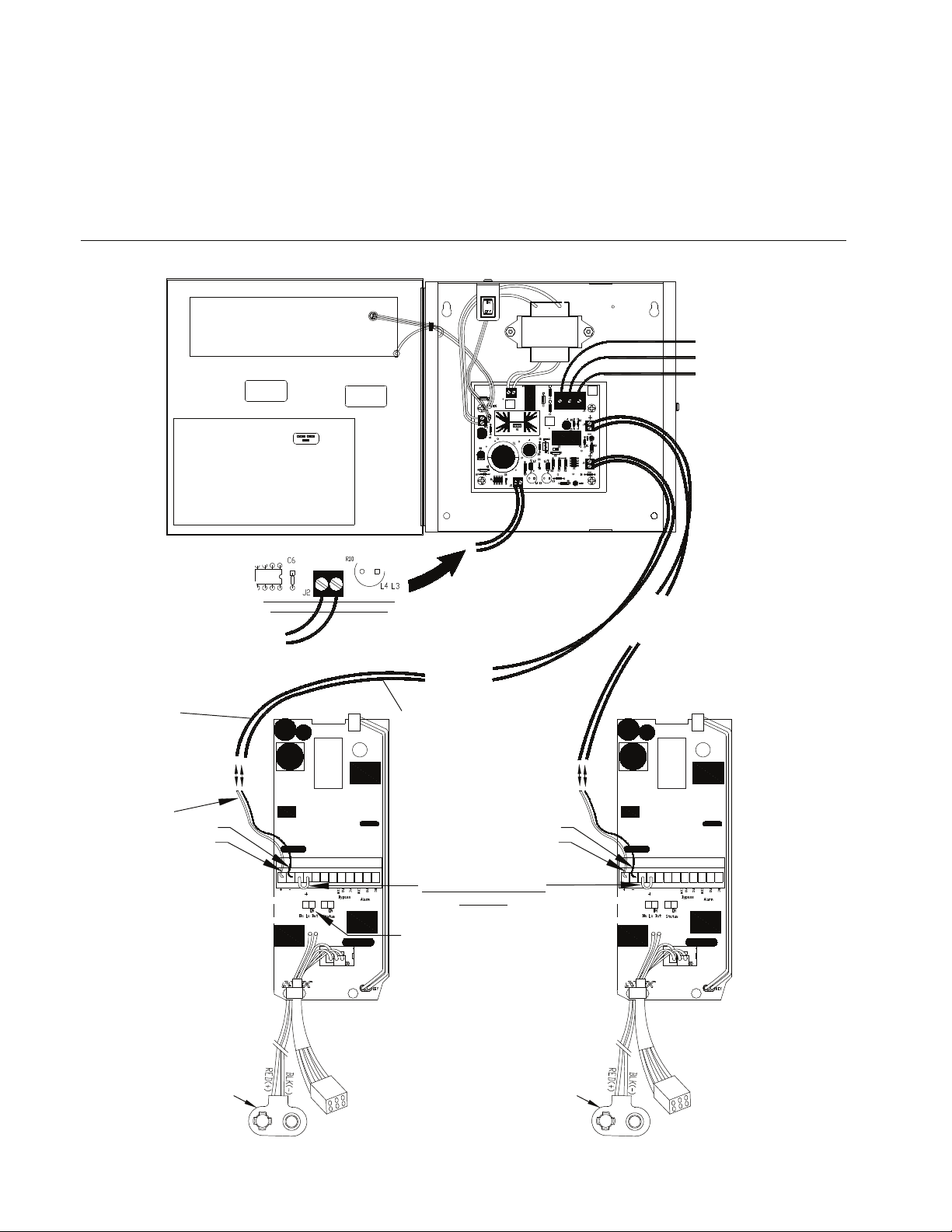
REQUIRES DETEX POWER SUPPLY
REQUIRED WIRE SIZES:
STRANDED WIRE GAUGE: 18 AWG MIN
MAXIMUM LENGTH OF TWO CONDUCTOR CABLE: 40 FEET
Detex requires one fire
alarm relay per power
supply
Closed Fire Alarm Loop
(must be supplied)
From (+)
terminal to
pin #1 on exit
device
EE ELECTRICAL OPTIONS
Power Supply with Detex Delayed Egress device
Fire
Loop
Sense
To Exit
Device
Door #1
From (-)
terminal to
pin #2 on exit
device
WHITE
BLACK
GREEN
RED
BLACK
RED
BLACK
DETEX REQUIRES THE
POWER SUPPLY BE
LOCATED WITHIN
40 FEET OF THE DEVICE
To Exit Device
Door #2
(if req'd)
RED/BLK WIRES
TO 24 VOLT
BLK
RED
9V Alkaline
Battery
BLK
RED
FACTORY INSTALLED
JUMPER
To disable the low-battery
indication, slide the Dis Lo
Bat switch to 'ON'
(PC BOARD ASSEMBLY INSIDE
DELAYED EGRESS DEVICE)
9V Alkaline
Battery
104832 Page 17
Page 18
Factory
installed
jumper
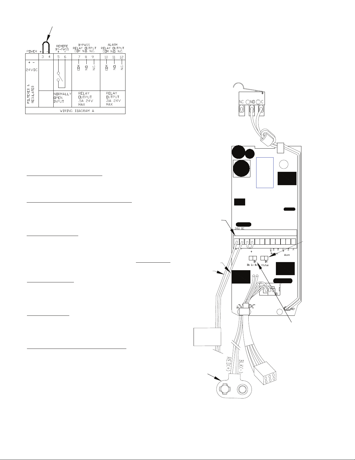
EE ELECTRICAL OPTIONS
L9= Less 9V battery
SI= Status Indicator
1 2
POWER REQUIREMENT:
.5 AMPS @ 24 VDC
The key cylinder arming switch must be set to "OFF". To prevent the alarm from
sounding during installation, attach battery AFTER main power is applied.
wer is applied.
Delayed Egress Device requires a connection to the Fire Alarm System.
The fire alarm connection needs to be made Externally at the Power Supply.
During a fire alarm condition the delayed egress will be by-passed.
MAIN POWER CONNECTION: (1 AND 2)
See Power Supply instructions
DETEX REQUIRES USING THE FIRE ALARM
CONNECTION IN THE POWER SUPPLY:
CLOSED connection is provided to the fire alarm system when
not in-alarm and OPEN when in-alarm. See power supply
instructions for details.
Removable
Terminal Block
REMOTE BY-PASS: (5 AND 6)
Connect normally open (N.O.) contact.
When the contact is closed momentarily, this will allow the
door to open without the alarm sounding. The unit will
automatically re-arm in 15 seconds after the
door is closed
(three quick audible beeps).
BY-PASS RELAY: (7,8 AND 9) DRY contact output.
The BY-PASS relay is energized when the unit is disarmed by
the KEY or REMOTE BY-PASS to indicate to a remote indicator
that the door is not armed.
ALARM RELAY: (10, 11 AND 12) DRY contact output.
The ALARM relay is energized when the unit is sounding its
alarm to indicate to a remote indicator that an unauthorized
exit has been attempted.
STATUS INDICATOR (SLIDE SWITCH)
ON: Green LED blinks every three seconds
when the unit is disarmed.
Red LED blinks every three seconds
when the unit is armed.
OFF: No status indication
-BLK
+RED
OBSERVE
POLARITY
24VDC
POWER SUPPLY
RED +24V
BLACK GROUND
9V Alkaline
Battery
1 2 3 45678 9 101112
Status
indicator
switch
Dis Lo Bat switch:
To disable the low-battery
indication, slide "DisLoBat"
switch to 'ON'
104832 Page 18
Page 19
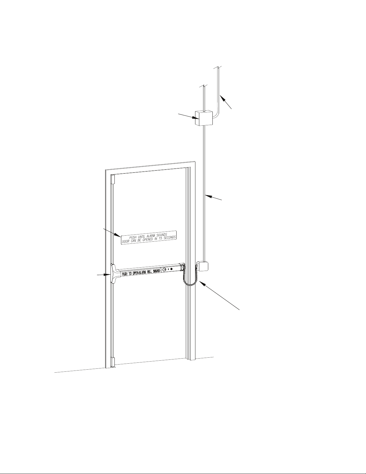
RISER DIAGRAM
DETEX FILTERED AND REGULATED POWER SUPPLY
WITH FIRE ALARM SYSTEM LOOP 24 VDC @1 AMP MIN
DETEX REQUIRES THE POWER SUPPLY BE LOCATED
WITHIN 40 FEET OF THE DEVICE
PROVIDE WIRING CONDUIT, CONNECTOR,
ETC BETWEEN DETEX POWER SUPPLY
AND FIRE ALARM CONTROL PANEL AS
REQUIRED TO ALLOW THE FIRE ALARM
SYSTEM TO OVERRIDE THE DETEX
DELAYED EGRESS FEATURE DURING
A FIRE ALARM.
THE LOSS OF POWER OR OPEN FIRE
ALARM CIRCUIT WILL ELIMINATE THE
DELAYED EGRESS FUNCTION
REQUIREMENTS:
MIN. 22 GA STRANDED WIRE FOR SIGNALING
MIN. 18 GA STRANDED WIRE FOR POWER
DOOR SIGN SUPPLIED WITH
DETEX DELAYED EGRESS
PANIC HARDWARE
DETEX DELAYED EGRESS
PANIC HARDWARE
INSTALLED BY
TRAINED TECHNICIAN
J
REFER TO WIRING &
FIRE ALARM DIAGRAMS
FOR WIRING
INSTRUCTIONS
104832 Page 19
Page 20
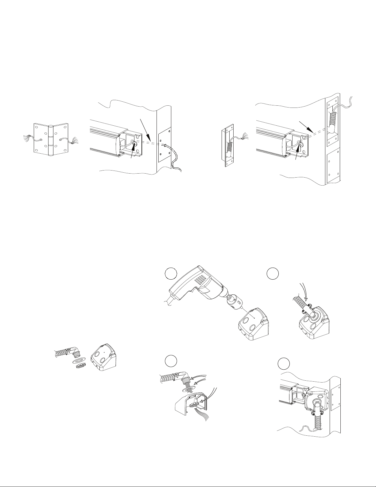
(Requirements: Minimum 6 Conductor Wires, Maximum 12 Conductor Wires)
Electric Hinge
Order by finish
p/n: EWH8-X
HARDWIRE TRANSFER OPTIONS
Electric Hinge Endcap Prep
Wire chase through door
(EE models)
Power Transfer Endcap Prep
Wire chase through door
1/2" Hole through the
inside door face
Power Transfer
p/n: PT-5
Note: For high traffic areas an electric through-wire hinge or power transfer
is recommended.
VALUE SERIES FLEX CONDUIT INSTALLATION
1
Value Series Flex
Drill 7/8" hole
through center guide
Conduit/End Cap Kit
Catalog No: FCV
1/2" Hole through the
inside door face
Adjust for handing
2
(LHR shown)
3
Fasten until
hand-tight
Note: For high traffic areas an electric through-wire hinge or power transfer
is recommended.
4
104832 Page 20
Page 21
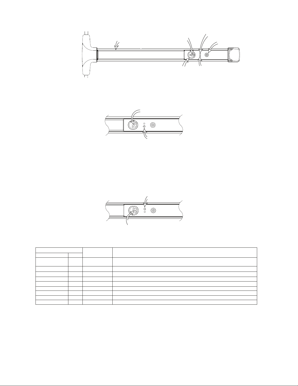
DELAYED EGRESS OPERATIONS
Red LED
Siren
Green LED
PushPad
(LHR shown)
Home
Key
Position
Mortise
Cylinder
ARMING AND AUTHORIZED EXIT
With door closed, insert key in the cylinder, turn CCW, then back to the home key position and remove it. LED glows
green. Authorized personnel can exit the door during the arming delay. After a 1, 5 or 15
second arming period, alarm issues three quick beeps and LED goes off, indicating that the unit is armed.
Turn Key CCW To Arm
Glowing Green LED
DISARMING
Insert key, turn CW to a stop. Green LED will blink twice to indicate the unit is disarmed.
EXITING UNDER ALARM
To exit, push and maintain pressure on the pushpad. After a one-second delay, (nuisance delay), LED flashes RED
and alarm pulses on and off for 15 seconds. After 15 seconds, alarm issues short and long pulses to indicate that
one can exit by depressing the pushpad.
Alarm sounds continuously and LED is steady RED. Turn key CW to stop alarm. In case of fire, the fire alarm
over-rides the 15 second delay
and the door opens without delay when the pushpad is pushed.
Red LED while alarming
NUISANCE DELAY
Turn Key CW To Disarm
When pushpad is depressed for less than 1 second, alarm will emit a single pulse but will not start delay function.
NORMAL OPERATION
LED COLOR
RED
OFF
OFF
ON
SLOW BLINKING
FAST BLINKING
ON
DOUBLE BLINK
BLINK
OFF
GREEN
BLINK
ON
OFF
ON
OFF
OFF
OFF
OFF
OFF
SIREN SOUNDS
THREE CHIRPS
SLOW PULSE
FAST PULSE
ON
DOUBLE CHIRP
FUNCTION
Indicates the unit is in process of arming. The siren will chirp three times to indicate the unit
is armed and green LED will turn off
This indicates either armed or disarmed
Factory installed jumper removed from 3 & 4 terminals
Pushpad is depressed, delay to open started
Delay to open expired
Delay to open expired, door has been opened
Low Battery - every 45 seconds
Armed - status ON
Disarmed - status ON
BATTERY BACKUP FOR ALARM
A 9-volt battery is included as a backup power source for the alarm siren if power is lost.
To disable low battery indication, slide the DisLoBat switch to 'ON'. See page 16 for location.
LOW BATTERY INDICATION
If battery voltage is low(7 volts or less), unit remains armed but LED flashes RED and unit beeps twice every
45 seconds. Replace ba
ttery as soon as possible.
104832 Page 21
Page 22

TROUBLESHOOTING
Problem
Alarm sounds when power is applied:
No green light when key is turned CCW:
No delayed egress:
Both red and green lights on:
Low battery signal-
Two chirps every 45 seconds:
Probable Cause
Turn key clockwise to OFF position.
Confirm strike is pushing in dead latch. Door must be closed.
Confirm 24VDC power on the delayed egress device main board
terminals 1(+) & 2(-).
Confirm closed fire loop connection on power supply.
Confirm cable is plugged in properly.
Confirm the mortise cylinder is functioning correctly.
Confirm closed fire loop connection on power supply.
Confirm the 2delayed egress main board.
Confirm 24VDC power on the delayed egress device main board
terminals 1&2.
Factory installed jumper removed from terminals 3 and 4.
Check battery. If no battery is needed, slide DisLoBat switch on
delayed egress main board to 'ON'. See electrical pages of instructions.
pin header with the two red wires are plugged into the
For further assistance, contact Detex Technical Support 1-800-729-3839
104832 Page 22
Page 23
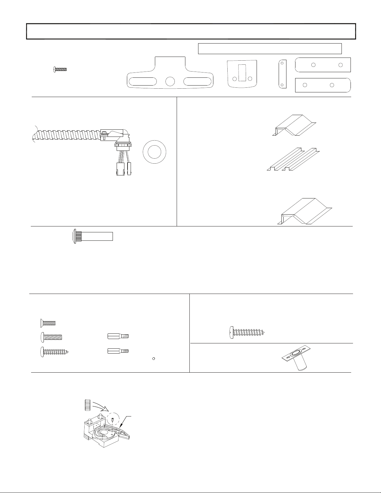
Glass Bead Kit
Catalog No: GB17 through GB21
#1/4-20 X 1-1/2" Self Drilling
screws Included
Optional Accessories
Flex Conduit Kit
Catalog No: FCV-3
FCV-10
Weatherized FCV-W-3
FCV-W-10
Sex Nut
The #10-32 kit is available in (4) finishes:
Catalog No: SN2 Brushed Brass BHMA 606 Finish
Catalog No: SN2 Oil Rubbed Bronze BHMA 613 Finish
Catalog No: SN2 Brushed Chrome BHMA 626 Finish
Catalog No: SN2 Stainless Steel BHMA 630 Finish
Rod Cover/Bottom Bolt Guard Kit
P/N:
103558-1 V50x84xRCxBG
103558-2 V50x96xRCxBG
103558-3 V50x120xRCxBG
103558-4 V51x84xRC
103558-5 V51x96xRC
103558-6 V51x120xRC
103558-7 V50x84xRC
103558-8 V50x96xRC
103558-9 V50x120xRC
Bottom Bolt Guard Kit
P/N: 103562
The #1/4-20 kit is available in (4) finishes:
Catalog No: SN1 Brushed Brass BHMA 606 Finish
Catalog No: SN1 Oil Rubbed Bronze BHMA 613 Finish
Catalog No: SN1 Brushed Chrome BHMA 626 Finish
Catalog No: SN1 Stainless Steel BHMA 630 Finish
Tamper Kit
(Security Kit)
Catalog No: SSK3
Security Screws
Key Stop Kit
(Momentary Shunt)
Catalog No: KS
Key Stop Screw
Security Pin TORX
Bits provided
Dogging Lever Assembly
(shown for reference ONLY)
R
104832 Page 23
Wood Door Screw Kit
Part No: 103991
Dustproof Strike Kit
Part No: 101562-X
 Loading...