

Page 1
101296 November 3, 2009
Detex Corporation, 302 Detex Drive, New Braunfels, Texas 78130-3045
(830)629-2900 / 1-800-729-3839 / Fax (830)620-6711
E-MAIL: [email protected] INTERNET: www.detex.com
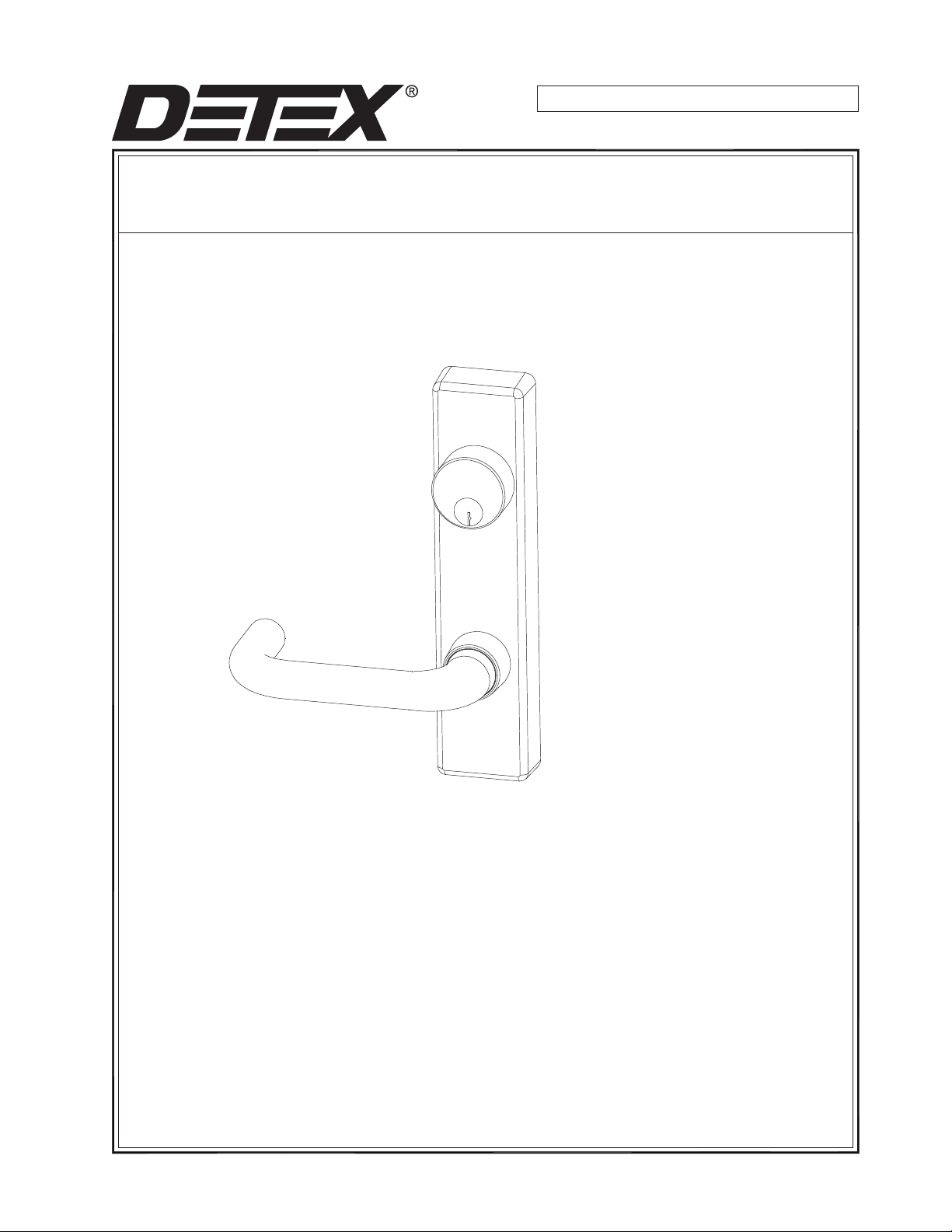
INSTALLATION INSTRUCTIONS FOR ADVANTEX NARROW TRIM
OUTSIDE LEVER TRIM 08/09/14
(08 Trim - includes 08DN, 08DNT, 08DNU)
(09 Trim - incl
udes 09DN, 09DNT, 09DNU)
(14 Trim - includes 14DN, 14DNT, 14DNU)
TOOLS AND SUPPLIES
Safety Glasses
(Always put on safety glasses prior to beginning installation of unit)
Pencil
1/8" Hex Wrench
Center Punch
Hammer
Drill Motor
Drill Bits & Taps
Screwdriver (Flat head & Phillips drive)
Tape Measure
DETEX INS-101296 Page 1
Page 2
PREPARING THE TRIM
1. The lever trim is handed. Refer to "CHANGE LEVER HANDING" on page 4 if needed.
INSTALLING THE MORTISE CYLINDER -08 and 09 FUNCTIONS ONLY
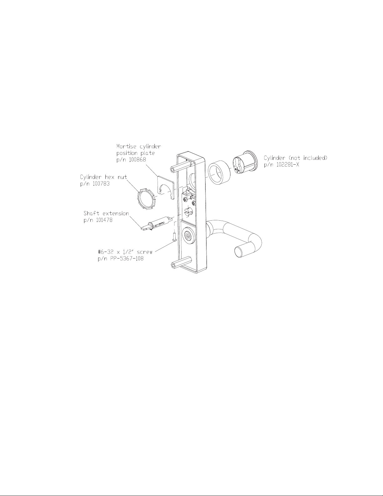
2. A short cylinder collar is supplied for mortise cylinders 1" to 1-1/8" long. For cylinders greater than 1-1/8", order
tall collar p/n 100752-x.
3. Insert the mortise cylinder (not included). (See Fig T8). Fasten th
Note: The key should turn the cylinder cam easily to slide the locking bar in both directions.
Caution: The back of the cylinder should not protrude beyond the depth of the trim escutcheon.
e cylinder with the large hex nut from the hardware kit.
Fig. T8
PREPARING THE TRIM - CONTINUED - FOR 08 FUNCTION, 09 FUNCTION AND 14 FUNCTION:
4. Attach the tailpiece extension assembly to the top gear with screw pr
PREPARING THE DOOR:
5. Center punch holes "a" and "d" marked earlier.
6. Drill two (2) pilot holes "a". Caution: Be sure to drill STRAIGHT through the door.
7. Drill pilot hole "d". Caution: Be sure to drill STRAIGHT through the door.
8. At the outside and inside hole "d", drill a 3/4" hole.
ovided.
DETEX INS-101296 Page 2
Page 3
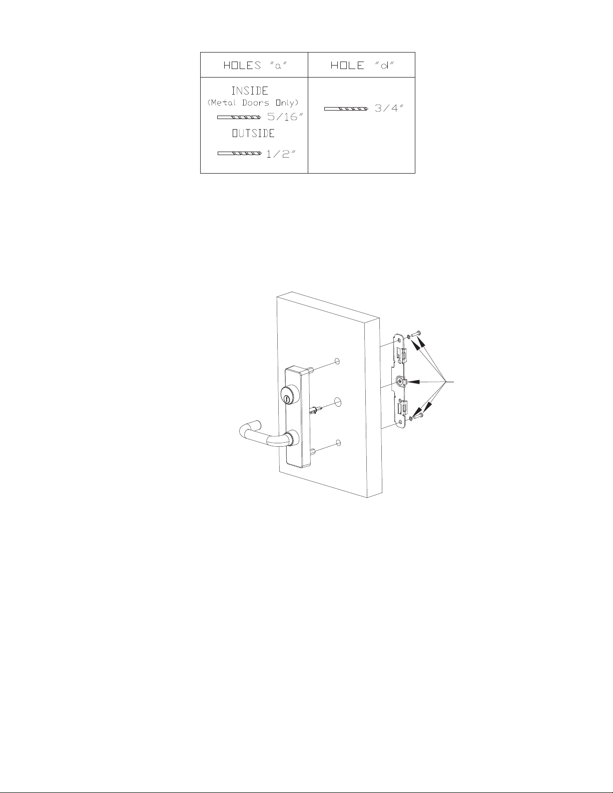
Fig. T9
9. Drill holes "a" according to the chart (Fig. T9).
ASSEMBLING THE OUTSIDE TRIM AND BACK PLATE
10. Align the hex stand-offs and trim assembly through the drilled holes (Fig T10).
Supplied with
panic device
Fig. T10
11. Align the tailpiece extension assembly into the backplate trim cam on the inside face of the door.
12. Fasten the backplate to the inside face of the door with lockwashers and 1/4-20 machine scr
Exit Device Hardware Kit. Caution: The lever should easily operate the inside trim cam.
13. Resume the panic hardware instruction.
ews provided with
DETEX INS-101296 Page 3
Page 4

CHANGE LEVER HANDING
(Refer to Fig T12 on page 5)
A. Remove tailpiece extension assembly screw. (remove tailpiece extension assembly if necessary).
B. Remove the hex standoff and the two (2) screws holding the spring retaining plate.
C. WARNING: Springs under pressure! Remove spring retaining plate.
D. switch lock spring to opposite side (for 09 Function only).
E. Carefully remo
ve the springs and bottom rack.
F. Remove the top rack.
G. Rotate lever to opposite side.
H. Engage the top rack on the opposite side as shown.
I. Engage the top rack on the opposite side as shown.
J. Install springs on the bottom rack.
K. Replace spring retaining plate and fasten the two (2) screws and the the standoff.
L. Replace tailpiece extension assembly and screw. Handing complete.
DETEX INS-101296 Page 4
Page 5
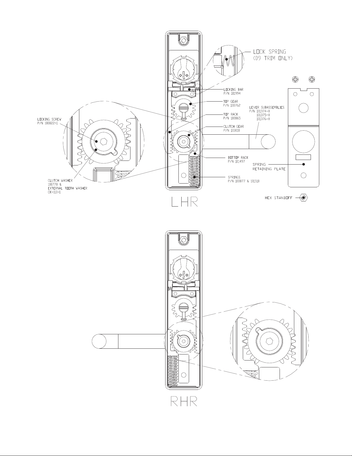
Fig. T12
DETEX INS-101296 Page 5
 Loading...