

Page 1
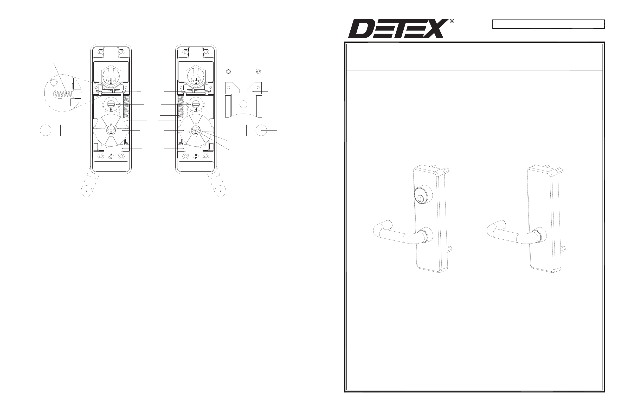
CHANGING LEVER HANDING
RHR LHR
103129 September 14, 2009
LOCK SPRING
(09 TRIM ONLY)
LOCKING BAR
TOP GEAR
INPUT SHAFT SCREW
SPRINGS
RACK
CLUTCH GEAR
STOP PLATE
SEE STEP H
LOCKING TAB
CENTER SCREW
SPRING
RETAINING PLATE
LEVER
Detex Corporation, 302 Detex Drive, New Braunfels, Texas 78130-3045
(830)629-2900 / 1-800-729-3839 / Fax (830)620-6711
E-MAIL: [email protected] INTERNET: www.detex.com
INSTALLATION INSTRUCTIONS FOR MORTISE OUTSIDE LEVER TRIMS
08DM, 08DMT, 08DMU
09DM, 09DMT, 09DMU
14DM, 14DMT, 14DMU
A. Remove input shaft screw. (Remove input shaft if necessary).
B. Remove stop plate.
C. WARNING: Springs under pressure! Remove spring retaining plate. Carefully remove the springs.
D. (For 09 Function only) Switch lock spring to opposite side.
E. Remove top gear.
F. Loosen the clutch center screw approximately two (2) turns. Bend locking tab
back to disengage with notch.
G. Slide the locking bar away from the rack (not necessary for 14 function). Remove the rack while rotating the lever.
H. Continue rotating the lever to the opposite side.
I. Rotate the lever to the position shown. Partially engage the rack and the clutch gear on the opposite side.
J. Rotate the lever until the rack is completely seated.
K. Insert the top gear.
L.
Add permanent thread locking adhesive and tighten the clutch center screw. Bend tab over screw notch
so that screw cannot turn.
M. WARNING: Springs under pressure! Install the springs. Hold the lever in the open position, firmly
compressing the springs in place.
08 or 09 LEVER TRIM 14 LEVER TRIM
N. While holding the lever in the open position, replace the spring retaining plate and fasten the two (2) screws.
O. Reverse
the stop plate and fasten the screw.
P. Replace input shaft screw. Handing complete.
DETEX 103129
Page 2
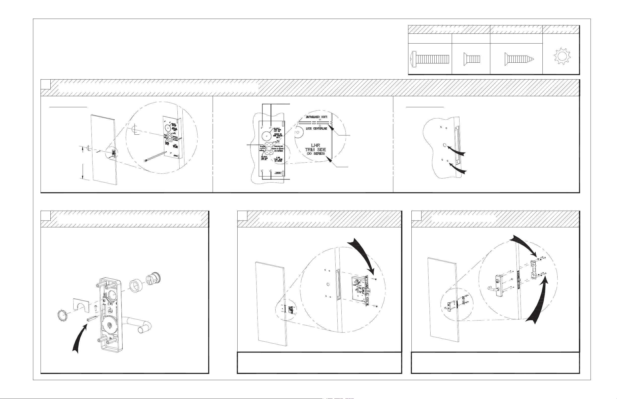
08, 09, 14 LEVER TRIM INSTALLATION INSTRUCTIONS
NOTES:
1) Mortise lock NOT supplied with TRIM device.
2) For a retrofit application, remove lock and device before installing new trim.
3) LHR installation shown (Reverse all steps for RHR).
STEP 1: PREP DOOR
Machine Screws
A
#1/4-20 x 1"
I
#12-24 x 1/2"
Sheet Metal / Wood Screw
J
#12 x 1"
Lock washer
#1/4 Lock washer
1
STEP 2: PREP TRIM DEVICE
2
TRIM side: Use plastic template to mark and drill TRIM holes
MARK HOLES DRILL HOLES
Mark trim
input hole
Mark centerline for
trim 40" above
finished floor
Mark trim holes
Lock Centerline
LHR Trim Side
Mark trim holes
STEPS 3-4: INSTALL MORTISE LOCK AND TRIM DEVICE
Install mortise cylinder and trim input shaft
3
Install MORTISE lock
4
Drill 3/4" diameter hole thru trim side only
Drill 1/2" diameter holes thru trim side only
4 places
Install TRIM device
NOTE:
1. Key should turn cylinder easily to slide locking bar in both directions.
2. Mortise cylinder installed on 08 & 09 trims only
3. Mortise cylinder NOT supplied with trim, but can be ordered
separately
Cylinder P/N: 102281-X
Short collar included
P/N: 100572-X
Install trim input shaft
Install lock with (2) "I" screws or
(2) "J" screws for wood doors.
IMPORTANT!
For modular cable devices, see electrical intructions for cable routing
#1/4 Lockwasher
Install backplate with
(4) "A" screws
TRIM INSTALLATION COMPLETE
Continue installation using device instructions (p/n:101349)
 Loading...