

Page 1
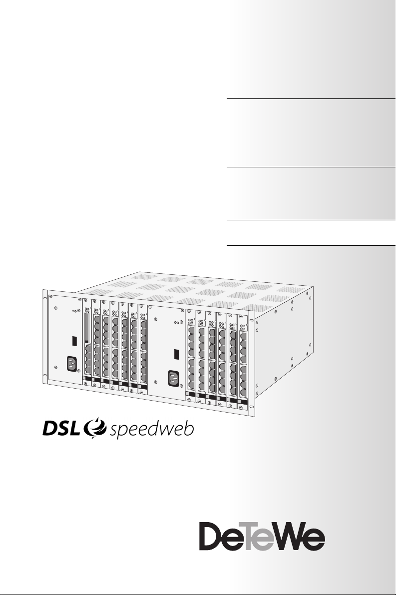
OpenCom 510
Mounting and Commissioning
User Guide
Page 2

Welcome to DeTeWe
Thank you for choosing this DeTeWe
product. Our product meets the
strictest requirements with regard to
quality and design.
The following instructions will guide
you in the operation of your
OpenCom 510 software and answer
most of the questions that may
arise.
If you require further technical support or information about other DeTeWe products, please refer to our
website at
OpenCom 100 Product
Family
This manual describe the communication system OpenCom 510.
For other members of the product
family, the following manuals exist:
■ OpenCom 100:
Manual for OpenCom 105,
OpenCom 107, OpenCom 110
and OpenCom 120
■ OpenCom 130/150:
Manual for OpenCom 130 and
OpenCom 150
www.detewe.de.
It provides additional notes and tips
on the product.
We hope you enjoy using
OpenCom 510.
■ OpenCom 510:
Manual for OpenCom 510
(19" housing)
We hope you enjoy using the
OpenCom 510.
Page 3

Contents
Features 5
Factory Settings 10
Telephony Functions 10
Authorisations 10
Internet Functions 13
Preliminary
Information 15
Construction of the
OpenCom 510 15
Scope of Delivery 16
Declarations of Conformity 16
Installation 17
Notes on Safety 17
General Instructions . . . . . . . . . . . . 17
Notes on the Mains Supply . . . . . . 17
Notes on EMC and Earthing . . . . . 18
Notes on Installing the
OpenCom 510. . . . . . . . . . . . . . 19
Notes on Installing Terminals . . . . 19
Siting, Ambient Conditions 20
Installation in a 19" Rack 21
Installing Modules 22
Slots . . . . . . . . . . . . . . . . . . . . . . . . . . 22
Notes on Disconnecting the
Mains Supply . . . . . . . . . . . . . . 23
Installing the Central Control
Module. . . . . . . . . . . . . . . . . . . . 23
Installing Interface Cards. . . . . . . . 25
Installing a Power Supply Unit . . . 27
Backplane 28
Uninterruptible Power Supply 30
Power Failure 31
Interfaces and Connectible Terminals 33
Overview 33
S
Ports 34
0
Termination . . . . . . . . . . . . . . . . . . . 35
External ISDN Ports (S
Internal S
U
pn
Ter min als Connected to U
Technical Information. . . . . . . . . . . 38
DECT Base Station Connection
a/b Ports 40
Terminals Connected to a/b Ports 40
Technical Information. . . . . . . . . . . 42
PCM Port 43
LAN Port 43
DSL . . . . . . . . . . . . . . . . . . . . . . . . . . . 43
Service PC . . . . . . . . . . . . . . . . . . . . . 44
COM Port 44
Accessories and Adapters 46
U
pn
a/b Adapter . . . . . . . . . . . . . . . . . . . 46
Audio Adapter . . . . . . . . . . . . . . . . . 46
Approved Devices /
Device Combinations . . . . . . . . . . . 49
Ports. . . . . . . . . . . . . . . . 37
0
Ports 38
Variants . . . . . . . . . . . . . . . . . . . 39
Adapter . . . . . . . . . . . . . . . . . . . 46
Approved Accessories . . . . . . . 48
External) . 36
0
Ports 38
pn
1
Page 4

Modules 52
Module Naming Conventions 53
Overview of Available Modules 54
MPS+1-AC 55
MC+1-3 57
MT+S2M1-1 60
MX+S01-8 63
MS+UPN1-8 65
MS+UPN2-8 66
MS+A1-8 68
Configuration 70
Brief Guide to Initial
Configuration 71
First Configuration via Serial Port . 71
System Requirements 72
Configuration under Windows 73
Connection on Serial Port (V.24) . .73
Notes on Configuring the
Serial Port . . . . . . . . . . . . . . . . . .75
Connection by Network Card
(LAN) . . . . . . . . . . . . . . . . . . . . . .75
Testing the Setup . . . . . . . . . . . . . . .76
Starting the Browser . . . . . . . . . . . .77
Configuration for Linux and
MacOS 77
Linux . . . . . . . . . . . . . . . . . . . . . . . . . .77
MacOS. . . . . . . . . . . . . . . . . . . . . . . . .78
Configuring the OpenCom 510 79
Preparing the Configuration . . . . .79
Starting the Web Console. . . . . . . .79
Loading the Online Help . . . . . . . . . 81
Finishing the Configuration . . . . . .82
Preconfiguration. . . . . . . . . . . . . . . .82
Remote Configuration. . . . . . . . . . .82
Codes for IP Configuration . . . . . . .83
Saving and Loading the
Configuration. . . . . . . . . . . . . . .84
Loading SW Updates . . . . . . . . . . . .84
Resetting the System Data . . . . . . .84
Generating Your Own MoH Files . .85
Configuration Examples
86
OpenCom 510 in Computer
Networks 86
Introduction to TCP/IP 87
OpenCom 510 in a Serverless
LAN 88
DNS Name Resolution . . . . . . . . . . .89
Internet Access . . . . . . . . . . . . . . . . .89
RAS Access . . . . . . . . . . . . . . . . . . . . .90
OpenCom 510 in a LAN
with an IP-enabled Server 91
DNS Name Resolution . . . . . . . . . . .91
Internet Access . . . . . . . . . . . . . . . . .92
RAS Access . . . . . . . . . . . . . . . . . . . . .92
LAN-to-LAN Link 94
Useful Information on
Internet Access 95
Costs . . . . . . . . . . . . . . . . . . . . . . . . . .95
Using the Web. . . . . . . . . . . . . . . . . .95
E-mail . . . . . . . . . . . . . . . . . . . . . . . . .96
NAT . . . . . . . . . . . . . . . . . . . . . . . . . . .96
PBX Networking 98
PBX Cascading 98
Functionality of PBX Cascading . . .98
Putting a Cascaded PBX into
Operation . . . . . . . . . . . . . . . . . .99
Notes. . . . . . . . . . . . . . . . . . . . . . . . .101
2
Page 5

PBX Networking 102
Connections . . . . . . . . . . . . . . . . . . 102
Types of Point-to-Point
Connection . . . . . . . . . . . . . . . 104
Configuration. . . . . . . . . . . . . . . . . 105
Technical Details . . . . . . . . . . . . . . 107
Licensing Information 109
Team Functions 110
Introduction 110
Explanation of Keys. . . . . . . . . . . . 110
Team Configuration . . . . . . . . . . . 112
Examples of Use 112
Executive/Secretary Team. . . . . . 112
Three-member Team . . . . . . . . . . 113
Unified Team . . . . . . . . . . . . . . . . . 114
Toggle Team . . . . . . . . . . . . . . . . . . 115
Call Queue 117
Introduction 117
Activation of Queues . . . . . . . . . . 118
Call Forwarding . . . . . . . . . . . . . . . 118
Pickup . . . . . . . . . . . . . . . . . . . . . . . 118
Hunt Groups . . . . . . . . . . . . . . . . . . 118
Examples of Use 119
Attendant Terminal for an
Operator with Two System
Telephones . . . . . . . . . . . . . . . 119
Group of Three Attendant
Terminals. . . . . . . . . . . . . . . . . 120
Multi-Company Variant
122
Configuring the Multi-Company
Variant 123
Activating the Multi-Company
Variant . . . . . . . . . . . . . . . . . . . 123
Configuring and Managing
Companies. . . . . . . . . . . . . . . . 124
Assigning Users . . . . . . . . . . . . . . . 124
Assigning Trunk Groups . . . . . . . . 125
Allocating Routing Codes . . . . . . 125
Configuring the Company
Exchange . . . . . . . . . . . . . . . . . 125
Working with the Multi-Company
Variant 126
Company Telephone Book. . . . . . 126
Making Calls Between
Companies. . . . . . . . . . . . . . . . 127
Billing Charges per Company . . . 127
Configuring the PC
Software 128
Setting up TAPI 128
Setting up NET CAPI 130
Using the Systray Display 131
Browser for OpenCTI 132
Synchronising the PC Clock 133
Address Queries using LDAP 134
USB DECT Box on the
OpenCom 510 135
General Information . . . . . . . . . . . 135
Installation and Configuration . . 135
Technical Data for Operation on the
OpenCom 510. . . . . . . . . . . . . 136
3
Page 6

Configuration Guide 137
Overview 138
PBX Ports 139
Easy Access 140
ISP Settings 141
RAS Settings 142
LAN-to-LAN Settings 143
E-mail Function 144
E-mail Access 145
Frequently Asked
Questions 146
General/Hardware 146
Telephony 147
DECT 149
LAN 150
Internet 151
Technical Data 153
4
Index 155
Page 7

Features
The OpenCom 510 is a communications system for integrated voice and
data communication. The most significant feature of this communications system is its modular structure.
The OpenCom 510 is designed for installation in a 19" frame. The frame
itself can be installed in a 19" wallmounted enclosure or in a 19" floorstanding cabinet.
The system provides a number of
slots for the installation of modules.
In a fully configured system, the following modules will have been installed (and all slots will be occupied): 2 power supply units,
1 cont rol module, 12 interface cards.
By combining different interface
cards, it is possible to create configurations suited to the user’s specific
communications requirements. If,
for example, a user requests DECTcapable U
S
or a/b interfaces, one or more in-
0
interfaces or additional
pn
terface cards can be integrated without having to exchange the entire
system.
Moreover, OpenCom 510 systems
can be cascaded, which allows you
to integrate a higher number of
modules, or networked in order to
meet growing communications requirements.
The OpenCom 510 can be integrated into system environments
with structured cabling. All connections to a structured cabling patch
panel can be made with standard
patch cables.
The OpenCom 510 supports the following communications applications:
■ Telephony with system tele-
phones, ISDN telephones and
analogue terminals, Internet/in-
tranet data communication,
CTI applications, sub-system op-
eration and system configura-
tion using a standard web
browser
■ Additional software packages
for expanded telephony func-
tions, e.g. the digital voicebox
and voice portal systems Open-
Voice and OpenAttendant
■ The “Doorline” intercom system
Tel eph on y
The OpenCom 510 communications
system is designed to be connected
to an ISDN basic access interface using the DSS1 protocol. Both multiterminal access (point-tomultipoint) and system access
(point-to-point) configurations are
supported. The system can be configured to run both types of access in
parallel. S
and S2M interface cards
0
are available for connecting the sys-
Features
5
Page 8

tem to the telecommunications network. An S
eight S
interface card provides
0
ports (switchable to either
0
internal or external connections).
The S
interface card provides one
2M
ISDN S
interface for connecting
2M
the OpenCom 510 either to a primary multiplex interface or to a second PBX (ISDN point-to-point connection). For an overview of
interface cards, refer to Modules
starting on page 52.
The OpenCom 510 firmware is designed for a maximum of 600 users.
For information on system limitations, refer to Technical Data starting
on page 153.
The following can be connected to
the OpenCom 510:
■ Euro ISDN terminals
■ DeTeWe system telephones
■ OpenPhone52 ISDN telephones
(to the U
■ DeTeWe RFP 21 base stations
pn
port)
ports are suitable for connecting
U
pn
the OpenPhone range of DeTeWe
system telephones. Furthermore,
the DECT-capable U
ports of the
pn
MS+UPN2-8 interface card can be
used to connect RFP 21 base stations.
Analogue ports are suitable for connecting standard analogue terminals.
If your network provider supports
the CNIP (Calling Name Identification Presentation) feature, the
names of callers will be displayed in
addition to the numbers whenever
external calls are received. The
OpenCom 510 supports the display
of the name on system telephones.
However, if you have created an entry in the telephone book under the
number of the caller, this entry will
be displayed instead.
The OpenCom 510 can be integrated into an existing local area
network (LAN) and used as an Internet access router and mail client by
all workstations in the LAN.
■ DECT handsets (with RFP 21 con-
nected to DECT-capab le U
pn
port
of MS+UPN2-8 interface card)
The OpenCom 510 can be configured
and programmed by means of a web
browser (web console). This browser
needs to be installed on a PC which
■ analogue terminals
S
interfaces must be operated with
0
Euro ISDN terminals in accordance
with the DSS1 protocol.
is connected to the system.
The OpenCom 510 can be pre-configured at the service centre and remote-configured for service purposes.
6
Features
Page 9

A COM port can be used to connect a
PC for the purpose of transferring
connection data.
You can use the “Doorline” intercom
system to connect the OpenCom 510
to a building’s wiring system, which
enables you to use door opener and
doorbell functions through the
OpenCom 510.
The OpenCom 510 enables you to
use third-party CTI (Computer Telephony Integration) applications.
This requires the installation of a
TAPI driver (provided on the system
CD-ROM) on a Windows PC. The
OpenCom 510 also features the integrated dialling wizard OpenCTI 50
with which users can call up and use
telephone functions through their
PCs without having to install a special TAPI driver.
Further Telephony Features
The OpenCom 510 can be used to
run digital voicebox and voice portal
systems. The configuration data and
the recorded speech files (messages
for, or left by, a caller) are stored on
the OpenCom 510 CompactFlash
card, which is installed on the
MC+1-3 central control module.
For further information, refer to the
“OpenVoice” and “OpenAttendant”
user guides.
You can optimize telephone communication with the help of team func-
tions and the call-queueing function.
The “OpenCount” application, which
requires a separate licence, can be
used to record and save connection
data; these data can be analysed using a number of individually configurable filter criteria. For further information, refer to the web console
online help.
You can connect two OpenCom 510
systems (PBX cascading). Cascading
is a simple way of increasing the
number of terminals that can be
connected.
As your communication requirements grow, the OpenCom 510 can
be networked with other telecommunications systems. The
OpenCom 510 can then operate as a
sub-system or as a DECT server. It is
also possible to create a telecommunications system with several networked PBXs.
Internet Access
For the purpose of providing Internet access, PCs can be connected to
the OpenCom 510 by means of the
internal S
can be connected by means of the
Ethernet port. If Internet access is already available from an Internet
service provider, the OpenCom 510
can be configured accordingly. The
OpenCom 510 can also be used for IP
configuration if there is no IP-capable client network. An integrated
ports, and an entire LAN
0
Features
7
Page 10

DHCP server and a DNS server will
take over IP address administration
and name resolution for the client
PCs.
The OpenCom 510 enables all connected PCs to access the Internet
using a common IP address; only the
common address will be visible outside the LAN. Network address translation (NAT) is used to change the IP
addresses of the local (client) PCs
into the IP address of the
OpenCom 510. This prevents direct
access to the LAN’s client PCs and
thus offers protection against attacks from the Internet. The
OpenCom 510 offers further protection of the LAN in the form of customisable filter lists (firewall function).
Note: Also observe the notes in
Useful Information on Internet Access
starting on page 95.
DECT Data Communication
PCs that are not connected to the
OpenCom 510 via the internal S
ports or the Ethernet interface can
access the Internet if used in combination with a USB DECT Box or the
OpenPhone 25 DECT terminals. PCs
in these configurations can also
make full use of the Internet and email features of the OpenCom 510.
Data will then be transmitted via the
internal data interface of the
OpenPhone 25, which must be connected to the serial port of the PC by
0
means of the supplied adapter. The
Internet can be accessed directly via
the remote data transfer (i.e. dialup) network. The OpenPhone 25 will
establish a data connection with the
OpenCom 510 via the DECT air interface. The Internet connection itself
will be established either directly
through an ISDN B-channel or indirectly through the internal RAS interface of the OpenCom 510. Indirect RAS access is preferable as it
uses the routing function of the
OpenCom 510 and thus benefits
from the security features of shared
Internet access.
The optional USB DECT Box enables
a PC to establish a wireless (DECT)
ISDN data connec tion. The USB DECT
Box and the PC are connected by
means of the USB interface.
For detailed information on installing the required driver software and
on the various configuration options, refer to USB DECT Box on the
OpenCom 510 starting on page 135
and to the “OpenPhone 25” user
guide. For information on configuring the OpenPhone 25 data interface, please refer to the
OpenCom 510 online help.
E-Mail
The OpenCom 510 offers an integrated e-mail function that supports
the POP3, APOP or IMAP4 protocols
used to query an Internet service
provider for incoming mail. The
OpenCom 510 can be configured to
8
Features
Page 11

enable every member of staff to
query mail accounts. The
OpenCom 510 fetches the incoming
e-mail headers (subjects) and senders from the mail server at set intervals and forwards them to the user’s
system terminal.
Further Network Features
You can enable staff to dial into the
LAN by means of RAS access.
In addition, you can configure a LANto-LAN link via ISDN. Two
OpenCom 510 systems can thus connect their LANs for on-demand dialin (from both sides).
A NET CAPI ( driver software provided
on the system CD-ROM) enables PCs
without ISDN cards to use ISDN functions.
Features
9
Page 12

Factor y Se tti ngs
The OpenCom 510 is delivered with
the following basic settings and activated features. We recommend that
you configure the OpenCom 510 to
meet your specific requirements before putting it into operation (see
Configuration starting on page 70).
Telephony Functions
■ The OpenCom 510 is pre-config-
ured for use in Germany.
■ Analogue terminals: The dial-
ling mode (pulse dialling or
DTMF) is detected automatically.
Tip: Notes on the functions listed
below can be found in the glossary
(provided as a PDF file on the system
CD-ROM).
■ Incoming external calls are sig-
nalled at all corded terminals
connected to the system.
■ The system PIN, which is used
for remote-programmable call
forwarding, for example, is
“0000”.
10
Authorisations
Authorisations determine which
functions can be used at the
terminals connected to the
OpenCom 510. Authorisations are
configured for so-called user groups;
users and their terminals are allocated to these groups.
Two user groups are preset: “Administrators” and “Guests”. “Administrators” have access to all functions of
Telephony Functions Factory Settings
the OpenCom 510 and unrestricted
configuration rights. Users in the
“Guests” group cannot configure the
OpenCom 510 or make external
calls, and have only restricted use of
the terminal functions of the
OpenCom 510.
Note: When the OpenCom 510 is
first put into operation, all connected
terminals are in the “Administrators”
Page 13

group until a user logs on to the web
console. All terminals are then automatically allocated to the “Guests”
group. For further information on
configuring user groups and users, refer to the online help chapter “User
Manager”.
are activated. Pickup protection
is deactivated.
■ “Call removal” is deactivated.
■ “Callback on busy” can be acti-
vated.
The following terminal functions are
preset for the “Administrators”
group:
■ External line access: Interna-
tional numbers can be called
from all configured telephones.
External lines must be seized by
entering a prefixed code.
■ Least cost routing (LCR) is not
active. As soon as LCR is configured, users can make calls using
selected call-by-call providers.
■ VIP call is activated.
■ Announcements to system ter-
minals are possible.
■ Baby calls can be configured.
■ If a call key is configured for a
user on more than one terminal,
he can program this key for
more than one outgoing call, i.e.
he can use his various terminals
to make parallel calls from this
telephone number.
■ “Pickup” and “Pickup selective”
of calls from other telephones
■ If a user has configured more
than one terminal under the
same number, they can suppress
the signalling of calls at the par-
allel terminals.
■ “Call queue” is deactivated.
■ “Reaction: Connection will be
disconnected” is deactivated as
callers trying to reach a terminal
that cannot be reached or is
busy will hear a busy signal.
■ Call forwarding to internal or ex-
ternal numbers can be activated.
Call forwarding after a certain
period of time is set to 20 sec-
onds. Door calls can be for-
warded. Forwarded calls are si-
multaneously signalled at the
original terminal and at the for-
warding destination. Call for-
warding can be configured for
specific MSN groups, provided
that MSN groups have been con-
figured. Users of the “Adminis-
trators” group can set call for-
warding for other users, their
own terminals, however, are
protected against call forward-
ing configuration by others.
Factory Settings Authorisations
11
Page 14

■ External calls can be transferred
to an external subscriber.
■ Three-party conferences can be
set up.
■ During a consultation call, the
waiting party hears music on
hold, provided a music-on-hold
file has been loaded into the system.
■ Call protection, call-waiting pro-
tection and intercom protection
are deactivated.
■ The presentation of the user’s
own phone number (MSN or system access number) on the display of the external party’s terminal is activated, but can be
suppressed.
vated for the user groups. A special list with emergency telephone numbers is preset and
activated.
■ External and internal calls not
answered by a user are entered
in their call list.
■ The door opener can be oper-
ated from all terminals. Door
calls can be forwarded.
■ Keypad dialling is possible.
■ The user group is not authorised
to change the system’s time
groups.
■ Call forwarding for SMS calls in
the fixed-lines network is not activated.
12
■ The telephone lock can be acti-
vated. The terminal PIN is
■ Connection data analysis is de-
activated.
“0000”.
■ The cost multiplier is set to
■ Interception of malicious callers
is possible if this feature has
100%, i.e. the costs are not mul-
tiplied by any factor.
been ordered from the network
operator.
■ Call charges can be recorded, as-
sociated with booking numbers
■ Speed dialling is possible, pro-
and analysed.
vided it has been configured in
the OpenCom 510 central telephone book.
■ The blacklist, the whitelist and a
call filter are not pre-configured
and thus not active. If these lists
■ Every user can change the con-
figuration of the OpenCom 510.
■ Every user can create a personal
telephone book and edit entries
in the central telephone book.
are configured, they can be acti-
Authorisations Factory Settings
Page 15

■ Every user can read out the
charges.
■ Every user can use the internal
OpenCount application for the
analysis of connection data.
use OpenCTI 50 to make calls,
manage calls and messages, dial
numbers from both the central
and personal telephone books,
and use the OpenCTI 50 busy
display.
■ Every user with a system termi-
nal who has a workstation can
Internet Functions
Note: E-mail, ISP and RAS access
cannot be configured unless you have
activated the OpenCom 510 IP package licence in the web console’s Con-
figurator in the SYS Configuration:
Licences menu (see also Information
Regarding the Licensing of the
OpenCom 510 IP Package on
page 14).
■ RAS access (with or without call-
back) can be configured for
every OpenCom 510 user, provided that RAS access is authorised.
■ More than one mail account
query can be configured for
every user.
■ The multi-company variant is
not activated.
OpenCom 510 web console or
from a system terminal that has
been configured accordingly).
The following IP addresses are preset for network configuration:
■ Host name: host
■ IP address: 192.168.99.254
■ Network mask: 255.255.255.0
The following addresses are transmitted to the LAN’s client PCs using
DHCP or PPP:
■ Gateway address:
192.168.99.254
■ Every user with a system termi-
■ Domain name: domain
nal can be automatically notified
of the receipt of e-mail.
■ Domain name server:
192.168.99.254
■ Users can terminate Internet
connections (through the
Factory Settings Internet Functions
13
Page 16

■ PPP addresses: 192.168.100.0 to
192.168.100.10
■ DHCP addresses: 192.168.9 9.129
to 192.168.99.148
You can change the IP settings in the
Configurator. Consult the LAN’s network administrator if you wish to do
so.
Information Regarding the
Licensing of the OpenCom 510
IP Package
You will need to obtain an activation
key in order to configure and use the
IP package in your communications
system.
To generate the activation key, visit
the DeTeWe licence server (http://lizenz.detewe.de).
The activation key is generated on
the basis of the serial number of
your OpenCom 510 and the transaction record (TAD). The licensing confirmation accompanying your IP
package contains your personal TAD
and all the information you need to
carry out this procedure.
14
Write down or print out the generated activation key.
Then activate the IP package on the
web console in the Configurator in
the SYS Configuration: Licences
menu. Additional information can
be found in the online help.
Internet Functions Factory Settings
Page 17

Preliminary Information
Construction of the OpenCom 510
The OpenCom 510 is designed to be
used in 19" rack systems. It comprises the following:
■ A 19" mounting frame for the
modules. In a fully configured
system, the following modules
will have been installed (and all
slots will be occupied): 2 power
supply units, 1 control module,
12 interface cards. The interface
cards provide the system ports.
The 19" frame of the
OpenCom 510 is also referred to
as the 1-12 frame (signifying the
number of slots for interface
cards).
■ A backplane. The backplane pro-
vides the sockets for the control
module and the interface cards;
it supplies the modules/cards
with the required power and
system signals.
cards ordered by the customer must
be installed separately.
Please note: Interface cards may
be installed by qualified personnel
only!
For further information on installing
modules/cards, please refer to In-
stallation in a 19" Rack starting on
page 21 and Installing Modules starting on page 22.
The OpenCom 510 comes fully assembled. By contrast with other systems, you will not need to assemble
the frame and backplane yourself.
A power supply unit and the central
control module are built into the
frame before delivery. Interface
Preliminary Information Construction of the OpenCom 510
15
Page 18

Scope of Delivery
The OpenCom 510 communications
system’s scope of delivery comprises
the following:
■ 1 19" frame (1-12 frame) with
slots for 1 control module and
up to 2 power supply units and
12 interface cards
The basic configuration of a 19"
frame includes the following
components:
– 1 BPV+1-12 backplane
–1 MPS+1-AC power supply
unit
– 1 mains cable for connection
to the mains supply
– 1 MC+1-3 control module
– 1 CompactFlash Card; the
firmware is stored on this card.
This card is included i n the scope
of delivery only if the 1-12 frame
is the first frame ordered and
not being used to expand the
OpenCom 510.
All other components (e.g. sec-
ond power supply unit, interface
cards and accompanying ca-
bles) are included as per the cus-
tomer’s order.
■ 1 RS-232 to RJ45 adapter cable
(for the V.24 interfaces of the
MC+1-3 control module)
■ 1 set of mounting brackets and
screws for installing the frame in
a 19" rack
■ 1 set of dummy covers for co-
vering unused slots
■ 1 set of short user guides
■ 1CD
16
Declarations of Conformity
The communications systems of the
OpenCom 100 product family comply with the requirements of EU directive 99/5/EC.
The declarations of conformity can
be found on the Internet at
http://www.detewe.de.
Scope of Delivery Preliminary Information
Page 19

Installation
Notes on Safety
The CE symbol on the product confirms that it meets the requirements
of the technical guidelines on user
safety and electromagnetic compatibility valid at the time of approval.
General Instructions
Please note: This product may be
installed and serviced by qualified
personnel only. Opening the housing
and carrying out unauthorised repairs may damage the product and
will invalidate the warranty.
DANGER! Hazardous voltages inside the device!
The MPS+1-AC power supply units
may not be opened as this may lead
to exposure to hazardous voltages!
Defective power supply units must
be sent to the manufacturer for repairs.
Always use the original packaging
when packing OpenCom 510 components for transport or storage.
CAUTION!
Static charge can damage the
OpenCom 510. Before and during
work on the electrical components of the OpenCom 510, discharge any static electricity from
your body and the tools you are
using.
Notes on the Mains Supply
The OpenCom 510 may be connected only to mains sockets with a
protective earth conductor.
Install the OpenCom 510 only near
easily accessible, wall-mounted
mains sockets.
Always use a dedicated circuit with
10-ampère protection to supply the
19" frame (1-12 frame).
If the OpenCom 510 is being powered by two MPS+1-AC power supply units, each of the two units must
be plugged into its own mains
Installation Notes on Safety
17
Page 20
socket. Do not use multiway mains
strips to connect more than one
OpenCom 510 power supply unit or
a OpenCom 510 and other devices to
the same mains supply.
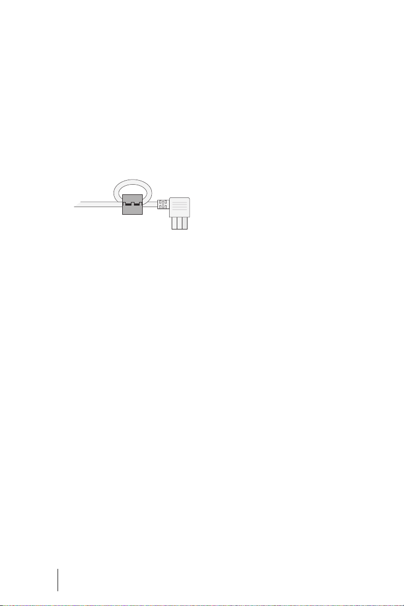
The mains cables of the MPS+1-AC
power supply units must have ferrite
rings fitted. The mains cables are
factory-fitted with ferrite rings.
Mains cable with ferrite ring
Install an overvoltage protection device.
Notes on EMC and Earthing
tion. This is normally the
OpenCom 510 housing.
Earthing and Potential
For the purpose of potential equalisation, all conductive parts of the
OpenCom 510 must be connected to
the protective earth conductor
(earth busbar of the building’s wiring system) by means of a solid or
stranded wire of at least 2,5 mm
(yellow/green).
2
18
Please note: MOS modules:
Observe the regulations regarding
modules and packaging carrying the
MOS trademark!
Use earthing wrist straps connected
to the appropriate points on the
frame (see C in the illustration
OpenCom 510: 1-12 frame mounting
points on page 21).
The mains socket’s protective earth
conductor and the telephone earth
line must be connected to one reference point for potential equalisa-
Notes on Safety Installation
Page 21
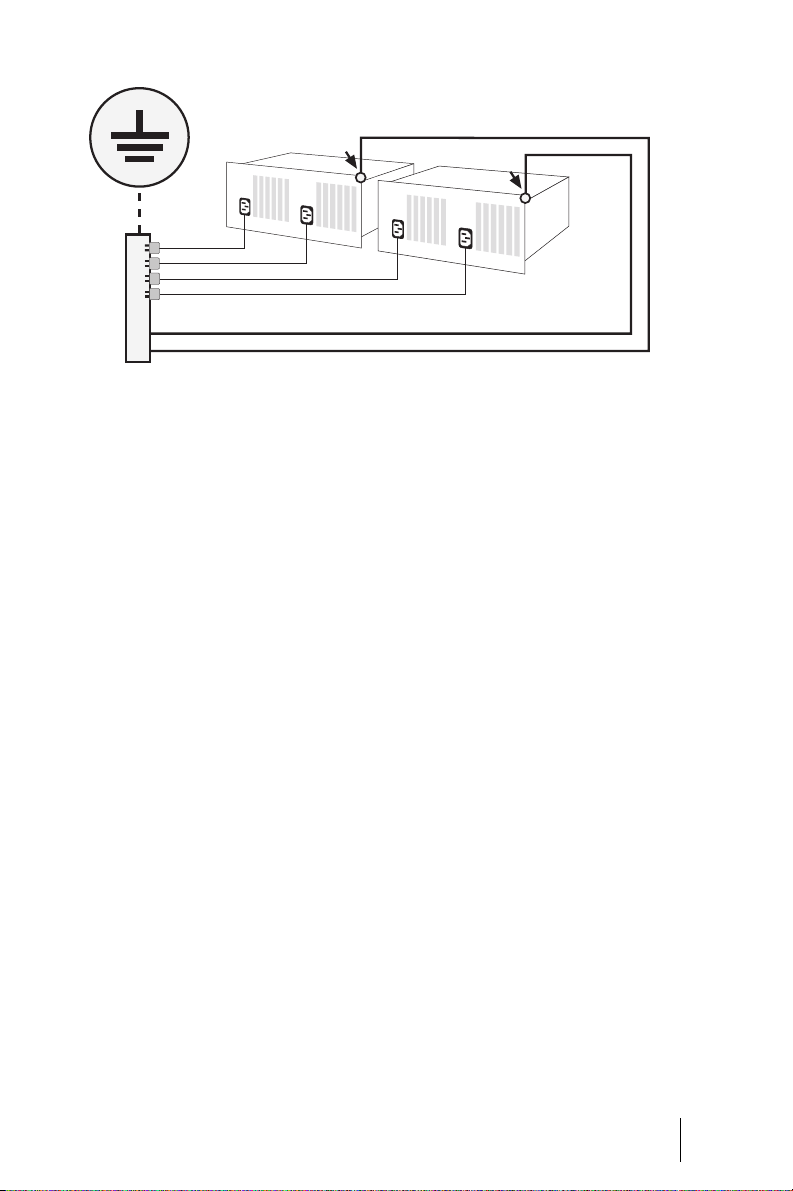
OpenCom 510: Earthing arrangement
ø 2,5 mm
ø 2,5 mm
2
2
The metal screens of the subscriber
and trunk cables must be connected
to the circuit common in the distributor or the patch field. The protective earth conductor of the 230 V
mains cables is connected to the circuit common and the telephone
earth line.
All metal parts of the communications system are mechanically and
thus electrically coupled in order to
provide protection through the protective earth conductor and the telephone earth line.
Notes on Installing the OpenCom 510
Do not allow any fluid to enter the
OpenCom 510 as this may cause
electric shocks or short circuits.
Do not install the OpenCom 510 during a thunderstorm. Do not connect
or disconnect any cables during a
thunderstorm.
The OpenCom 510 is designed for indoor use only. Route the cables in
such a way that they cannot be
stepped on or tripped over.
The OpenCom 510 must be securely
screwed into the frame when installation work on the system is interrupted or terminated. Unused slots
must be covered with dummy covers
(included in the scope of delivery).
Notes on Installing Te rm in a ls
Only devices that supply safety extra-low voltage (SELV) may be connected to the OpenCom 510. Proper
use of standard terminals will satisfy
this requirement.
The analogue interfaces may only be
used to connect terminals that meet
Installation Notes on Safety
19
Page 22

the appropriate technical requirements. For details, refer to a/b Ports
starting on page 40.
Use a shielded Ethernet cable (STP
cable, Shielded Twisted Pair cable) to
connect the OpenCom 510 to a Local
Area Network (LAN).
Siting, Ambient Conditions
The ambient temperature for operating the OpenCom 510 must be between +5 °C and +40 °C.
To maintain a safe ambient temperature, install the OpenCom 510 in a
properly ventilated location, away
from sources of direct heat.
Do not site the OpenCom 510
■ in front of or above heat sources
such as radiators,
■ in direct sunlight,
■ behind curtains,
■ in small, unventilated, damp
rooms,
■ near flammable materials,
■ or near high-frequency devices
such as transmitter and radiotherapy or similar apparatus.
that the air intake temperature does
not exceed +40 °C.
The OpenCom 510 may also be connected to an IT system.
20
If the OpenCom 510 is to be install ed
together with other electronic
equipment in a 19” cabinet, ensure
Siting, Ambient Conditions Installation
Page 23
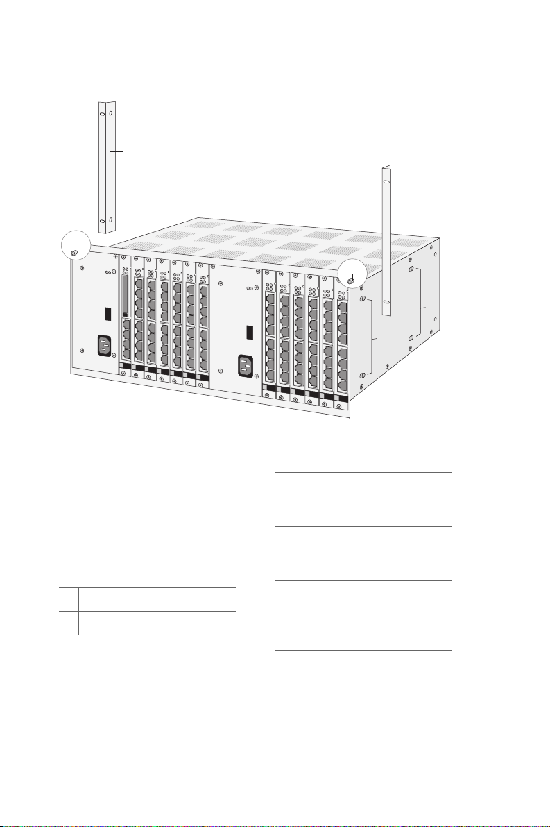
Installation in a 19" Rack
1
C
OpenCom 510: 1-12 frame mounting points
2
C
B
A
The OpenCom 510 is designed to be
installed in 19" racks only.
The following mounting points for
installation in a 19" rack can be
found on the 1-12 frame:
Legend
1 Left mounting bracket
2Right mounting bracket
Legend
A Mounting bracket screw bolts for
front mounting (approx. 132 mm)
to the uprights of the 19" rack
B Mounting bracket screw bolts for
mid-mounting (approx. 400 mm)
to the uprights of the 19" rack
C Left and right screw points for
earthing wrist strap or circuit
common connection between
1-12 frame and 19" rack
Note: If the OpenCom 510 is to be
used as a wall-mounted instead of a
floor-standing system, it must be installed in a standard-type wallmounted enclosure using 19" mounting technology.
Installation Installation in a 19" Rack
21
Page 24
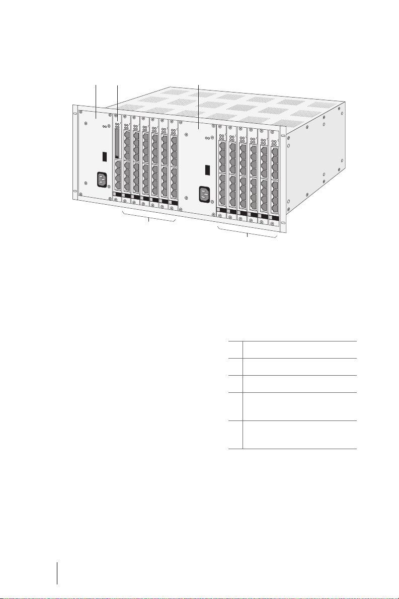
Installing Modules
A
0 B
C (1-6)
OpenCom 510: 1-12 frame slots
D (7-12)
22
Slots
The following slots are provided for
installing these modules:
The OpenCom 510 1-12 frame can
house up to:
■ 2power supply units
■ 1 control module
■ 12 interface cards (trunk or sub-
scriber modules) split into
2 separate groups.
Legend
A Slot for group 1 power supply unit
B Slot for group 2 power supply unit
0 Slot for central control module
C Slots for group 1 interface cards
(slots 1 - 6)
D Slots for group 2 interface cards
(slots 7 - 12)
Each of the two groups (1 or 2, or C
and D, respectively, in the illustra-
tion) requires its own power supply
unit. Power for the control module is
always supplied by the group 1
power supply unit. The group 1
Installing Modules Installation
Page 25

power supply unit must therefore always be installed.
Modules can be installed either
when the entire system is configured
or as an upgrade at a later time.
Notes on Disconnecting the Mains Supply
DANGER! Hazardous volt-
ages inside the device!
The OpenCom 510 must be disconnected from the mains supply for
the following installation work:
■ Installation of the central control
module
■ Installation of a power supply
unit
If a 1-12 frame is being powered by
two power supply units, it is de-energised by unplugging both mains
cables.
DANGER! Always unplug the
mains cables of both power supply units when installing the central control module or a power
supply unit.
If you unplug the mains cable of the
group 2 (B) power supply unit, the
OpenCom 510 will still be operational! However, only the modules
supplied by the group 1 (A) power
supply unit, i.e. the central control
module and the interface cards in
slots 1 - 6, will be functional.
If you unplug the mains cable of the
group 1 (A) power supply unit, the
OpenCom 510 ceases to be operational. However, slots 7 - 12 (D) will
still be supplied with operating voltage. (Refer to the illustration
OpenCom 510: 1-12 frame slots on
page 22 to determine the location of
the modules specified in parentheses above.)
The LEDs of each module indicate
whether the respective module is
operational. For further information
on LED indicators, refer to Modules
starting on page 52.
Installing the Central Control Module
The OpenCom 510 comes with the
central control module installed.
Should you need to exchange the
central control module, proceed as
follows:
1. Shut down the OpenCom 510. To
do so, first restart the system by
– entering the code procedure
H*185 (system
PIN)
# on a connected tele-
phone, or
Installation Installing Modules
23
Page 26

– clicking on Restart in the
SYS Configuration: Restart
menu in the Configurat or.
2. Wait until the LEDs of the installed modules start flashing
red.
DANGER! Hazardous voltages inside the device!
3. Unplug all of the mains cables of
the OpenCom 510 to disconnect
the system from the mains supply.
The central control module must
not be installed if the
OpenCom 510 is switched on!
Refer to Notes on Disconnecting
the Mains Supply starting on
page 23.
CAUTION!
Static charge can damage electronic devices. Observe the regulations regarding electrostatically sensitive components.
6. Carefully push the central control module into slot 0 (see also
the illustration OpenCom 510: 1-
12 frame slots on page 22). The
printing on the front of the module should be at the top.
Ensure that the backplane plug
of the central control module is
securely plugged into the socket
on the backplane.
7. Refit the screws to secure the
module in the 1-12 frame.
24
4. Remove the screws with which
the central control module is secured in the 1-12 frame and pull
the module out.
5. Unpack the central control module.
Installing Modules Installation
8. Plug the desired cables into the
corresponding RJ45 sockets on
the central control module. Refer to Modules starting on
page 52 for information on pin
assignment.
9. Switch the OpenCom 510 on
again. To do so, reconnect the
group 1 power supply unit (see
A in the illustration
OpenCom 510: 1-12 frame slots
on page 22) with the mains supply (if you are powering the
Page 27

OpenCom 510 with two power
supply units, reconnect the second unit as well).
The system will now start up and
all modules (interface cards) will
be re-initialised.
10. Observe the module LEDs during
start-up of the OpenCom 510.
Information on indicators can be
found in Modules starting on
page 52.
Note: The MAC address for the
OpenCom 510 is assigned by the central control module and cannot be
changed. If the central control module has to be exchanged, you may
need to change the IP settings. For
further information on MAC addresses, refer to the online help.
Explanatory Note on Shutting
Down the System
If the OpenCom 510 is disconnected
from the mains supply, its main
memory is deleted. The main memory stores the current configuration
data, which are regularly copied to
the CompactFlash memory card. Restarting the system causes it to copy
the current configuration data from
the main memory to the CompactFlash card, which ensures that the
most recent configuration is restored
when the system is started up.
Installing Interface Cards
Interface cards can be installed or
exchanged with the system powered
up (“hot-plugging”). Proceed as follows:
1. If you want to exchange an interface card, the slot for this card
needs to be deactivated first.
Open the PBXConfiguration:
Ports: Slots page in the Configurator. In the table row listing
the card to be exchanged, click
on Stop. The system then deactivates the slot. Any connections
(telephone calls, data transfers)
established through this card
will be terminated.
2. Remove the screws with which
the interface card is secured in
the 1-12 frame and pull the card
out.
3. Unpack the interface card and
check whether it is the desired
type. The type designation is
printed on the front of the card.
Installation Installing Modules
25
Page 28

MX+S01-8
S0 1S0 2
Detail: Printing on the front of an
“MX+S01-8” type interface card
CAUTION!
6. Plug the desired cables into the
corresponding RJ45 sockets on
the interface card. Refer to Mod-
ules starting on page 52 for information on the pin assignment for each interface card.
7. Cover any unused slots with
dummy covers (included in the
scope of delivery).
The dummy covers must be securely screwed to the frame!
8. If you have exchanged the interface card, you will need to reactivate the slot for this card.
Static charge can damage electronic devices. Observe the regulations regarding electrostatically sensitive components.
4. Carefully push the interface card
into the corresponding slot. The
printing on the front of the module should be at the top (see illustration in previous instruction).
Ensure that the backplane plug
of the interface card is securely
plugged into the socket on the
backplane.
5. Refit the screws to secure the interface card in the 1-12 frame.
Open the PBX Configuration:
Ports: Slots page in the Configurator again. In the table row
listing the card that has been exchanged, click on Start.
9. Observe the LEDs on the card.
Information on indicators can be
found in the chapter Modules
starting on page 52.
Checking the Status of the
Interface Cards via the Web
Console
You can also check the status of the
interface cards via the Web console
of the OpenCom 510.
1. Open the PBX Configuration:
Ports: Slots page in the Configurator.
26
Installing Modules Installation
Page 29

2. In the Status table row, check
whether a green tick is displayed
for the newly installed interface
card. The tick indicates that the
interface card is operational.
Installing a Power Supply Unit
– clicking on Restart in the
SYS Configuration: Restart
menu in the Configurator.
2. Wait until the LEDs of the installed modules start flashing
red.
Depending on the number of installed modules (interface cards), either one or two power supplies are
required (see A and B in the illustration OpenCom 510: 1-12 frame slots
on page 22):
■ The power supply unit for
group 1 (A) must always be installed. It supplies the central
control module and the interface cards in slots 1 - 6.
■ The power supply unit for
group 2 (B) is required if interface cards are to be installed in
in slots 7 - 12.
If you want to deinstall the second
power supply unit or exchange a defective one, proceed as follows:
1. Shut down the Ope nCom 510. To
do so, first restart the system by
DANGER! Hazardous voltages inside the device!
3. Unplug all of the mains cables of
the OpenCom 510 to disconnect
the system from the mains supply.
Power supply units must not be
installed if the OpenCom 510 is
switched on! Refer to Notes on
Disconnecting the Mains Supply
starting on page 23.
4. Unpack the power supply unit.
CAUTION!
– entering the code procedure
H*185 (system
PIN)
# on a connected tele-
phone, or
Static charge can damage electronic devices. Observe the regulations regarding electrostatically sensitive components.
Installation Installing Modules
27
Page 30

5. Carefully push the power supply
unit into the corresponding slot
(see also the illustration
OpenCom 510: 1-12 frame slots
on page 22). Seen from the
front, the mains inlet socket
should be on the bottom right.
8. Switch the OpenCom 510 on. To
do so, reconnect the power supply unit with the ma ins supply (if
you are powering the
OpenCom 510 with two power
supply units, connect the second
unit as well).
Ensure that the backplane plug
of the power supply unit is securely plugged into the socket
on the backplane.
6. Refit the screws to secure the
power supply in the 1-12 frame.
7. Install further interface cards if
required (see also Installing In-
terface Cards starting on
page 25).
Backplane
The BPV+1-12 backplane of the
OpenCom 510 supplies the modules
installed in the 1-12 frame with the
required power and system signals.
The backplane is also used to provide access to the PCM highway (for
transmitting utility data), the LAN
(for exchanging signalling data) and
to the system clock circuits.
The system will no w start up and
all modules (interface cards) will
be re-initialised.
9. Observe the module LEDs during
start-up of the OpenCom 510.
Information on indicators can be
found in the chapter Modules
starting on page 52.
■ The MPS+1-AC power supply
units and the MC+1-3 central
control module are each connected by means of a 96-pin
spring contact strip.
■ The interface modules are each
connected by means of a 48-pin
spring contact strip.
28
The backplane has vertically arranged sockets for the backplane
plugs of the modules:
Should you need to exchange the backplane, proceed as follows:
Backplane Installation
The backplane also carries the system serial number (etched into the
backplane chip).
Page 31
DANGER! Hazardous voltages inside the device!
2. Deinstall all modules and power
supply units from the 1-12
frame (see Installing Modules
starting on page 22).
1. Unplug all of the mains cables of
the OpenCom 510 to disconnect
the system from the mains supply.
Refer to Notes on Disconnecting
the Mains Supply starting on
page 23.
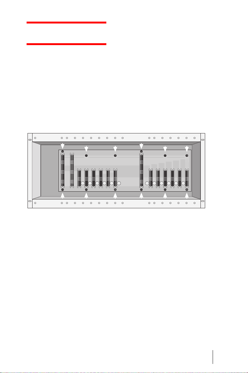
OpenCom 510: Backplane screws
4. From the front, insert the new
backplane into the 1-12 frame.
Insert and tighten the screws to
secure the backplane in the 1-12
frame.
5. Reinstall the modules in the designated slots.
6. Cover any unused slots with
dummy covers (included in the
scope of delivery).
3. Remove the screws on the backplane (see arrows in the illustration OpenCom 510: Backplane
screws). Carefully remove the
backplane from the 1-12 frame,
pulling it out of the frame towards the front.
The dummy covers must be securely screwed to the frame!
7. Switch the OpenCom 510 on
again. To do so, reconnect the
power supply unit with the
mains supply (if you are powering the OpenCom 510 with two
power supply units, connect the
second unit as well).
8. Observe the module LEDs during
start-up of the OpenCom 510.
Information on indicators can be
Installation Backplane
29
Page 32

found Modules starting on
page 52.
the System Info: Versions menu
in the Configurator.
If you were using software packages subject to licensing (e.g.
the internal voice mail program
OpenVoice) prior to exchanging
the backplane, this software
needs to be reactivated using
new activation keys. Contact
your dealer or DeTeWe distributor.
9. The new keys will be generated
using the backplane serial
number. You will be required to
state this serial number. You can
determine the serial number in
10. Enter the new activation key in
the SYS Configuration: Licences
menu in the Configurator. This
will reactivate the software
packages.
The backplane serial number is
also used to encode the PARK of
a DECT system. If you are using a
DECT system with the
OpenCom 510, you will need to
re-enter the PARK.
11. You can determine the new
PARK in th e System Info: Ver-
sions menu in the Configurator.
Uninterruptible Power Supply
If you are using uninterruptible
power supplies (UPS), you must provide a separate UPS either for the
power supply of each frame (cascaded PBXs, see PBX Cascading starting on page 98) or for the power
supply of both frames. If one UPS is
used for both frames, it must be
earthed separately.
An MPS+1-AC power supply unit has
a leakage current of < 0.5 mA.
A 900-watt UPS is entirely sufficient
to power the OpenCom 510 (this
also applies to cascaded systems).
30
The total leakage current must not
exceed 3.5 mA per mains socket. Use
the leakage current specified by the
UPS manufacturer as a reference.
Uninterruptible Power Supply Installation
Page 33

Power Failure
In the event of a power failure, the
system memory will retain all data
(program and user data) without
any changes.
The internal clock will continue to
run for 24 hours. If the power failure
lasts longer than 24 hours, the time
and date will be reset to the factory
setting when power is switched on
again, and updated (by means of a
signal from the exchange) after the
first external outgoing call.
With multi-terminal access configurations, the OpenCom 510 provides
an emergency service feature: In the
event of a power failure, the S
terface will be switched to the S
1 in-
0
8
0
interface, enabling you to make calls
through a connected terminal.
The following is required to enable
emergency service:
■ An MX+S01-8 interface card
must be installed.
■ Port S
8 must be configured as
0
an internal connection. An ISDN
telephone with emergency service capabilit y must be connected
to this port.
Note: Emergency service is not possible with system access configurations.
Testing the Power Failure Circuit
You can test the configuration as follows:
1. Disconnect the OpenCom 510
from the mains supply (see instructions in Installing the Cen-
tral Control Module starting on
page 23, steps 1 to 3).
2. Disconnect the NTBA from the
mains supply.
3. It should now be possible to
make external calls through the
ISDN telephone connected to
port S
8.
0
■ The power failure circuit of this
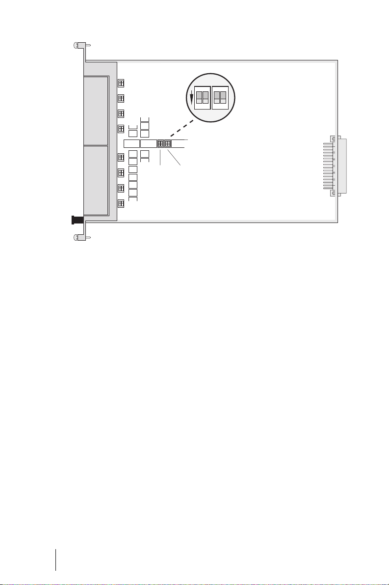
interface card m ust be activated.
To do so, set DIP switches S17 to
S20 to “ON”. The inter face card is
delivered with the power failure
circuit deactivated (default: off).
■ Port S
1 must be connected to
0
an NTBA (multi-terminal access)
and configured as an external
connection.
Installation Power Failure
31
Page 34
1
1
2
2
ON
ON
S17/18 S19/20
MX+S01-8: Location of the DIP switches for the power failure circuit
32
Power Failure Installation
Page 35

Interfaces and Connectible Te rm in al s
Overview
The OpenCom 510 interfaces have
been implemented as RJ45 sockets
nected by means of standard patch
cables.
on the front of the interface cards
and the central control module. No
special proprietary cables are required. Patch panels can be con-
Overview: Interfaces and Interface Cards
Interface Card Properties Page
S
0
S
2M
U
pn
U
pn
a/b MS+A1-8 8 a/b interfaces 68
PCM MC+1-3 1 PCM port
LAN MC+1-3 1 Ethernet port (10/100 Mbits/s)
MX+S01-8 8 S0 interfaces for either external or inter-
nal connections
MT+S2M1-1 1 S2M interface for connecting to digital
networks (primary multiplex connections)
or for cascading two PBXs
MS+UPN1-8 8 Upn interfaces, not DECT-capable 65
MS+UPN2-8 8 Upn interfaces, not DECT-capable 66
(on central control module)
(on central control module)
For technical information on the in-
terfaces, refer to Modules starting on
page 52.
63
60
57
57
COM / V.24 MC+1-3 2 V.24 ports
(on central control module)
57
The following terminals and systems
can be connected to the
OpenCom 510:
Interfaces and Connectible Terminals Overview
33
Page 36

Overview: Interfaces and Connectible Terminals
Interface Terminals/Systems Page
S0 (internal) ISDN terminals (DSS1 protocol):
telephones, fax machines, base stations and handsets, ISDN
cards for PCs
U
pn
a/b Analogue terminals:
PCM Connection of a second PBX (PBX cascading) 43
LAN Connection to a LAN (local area network) or of a DSL
COM / V.24 Connection of a PC (for transmitting connection data) 44
Digital terminals (ISDN terminals, system telephones) and
DECT base stations
telephones, G3 fax machines, (external or internal) modems, external music-on-hold devices, external voice mail
systems, external intercom systems
modem
S0 Ports
All of the eight S0 interfaces on the
MX+S01-8 interface card are switchable, i.e. they can be used either for
external connections (ISDN basic access or a second PBX) or for internal
connections (ISDN terminals). It is
not possible to use these interfaces
simultaneously for both types of
connections.
The S
ports have been imple-
0
mented as RJ45 sockets.
Pin Assignment
++– –
12345678
S
interface pin assignment
0
The following table explains the S
interface pin assignment.
34
38
40
43
0
34
S0 Ports Interfaces and Connectible Terminals
Page 37
Pin Number Assignment
Te rm in a ti on
1 Not used
2 Not used
3Send +
4 Receive +
5 Receive -
6Send -
7 Not used
8 Not used
2
ON
1
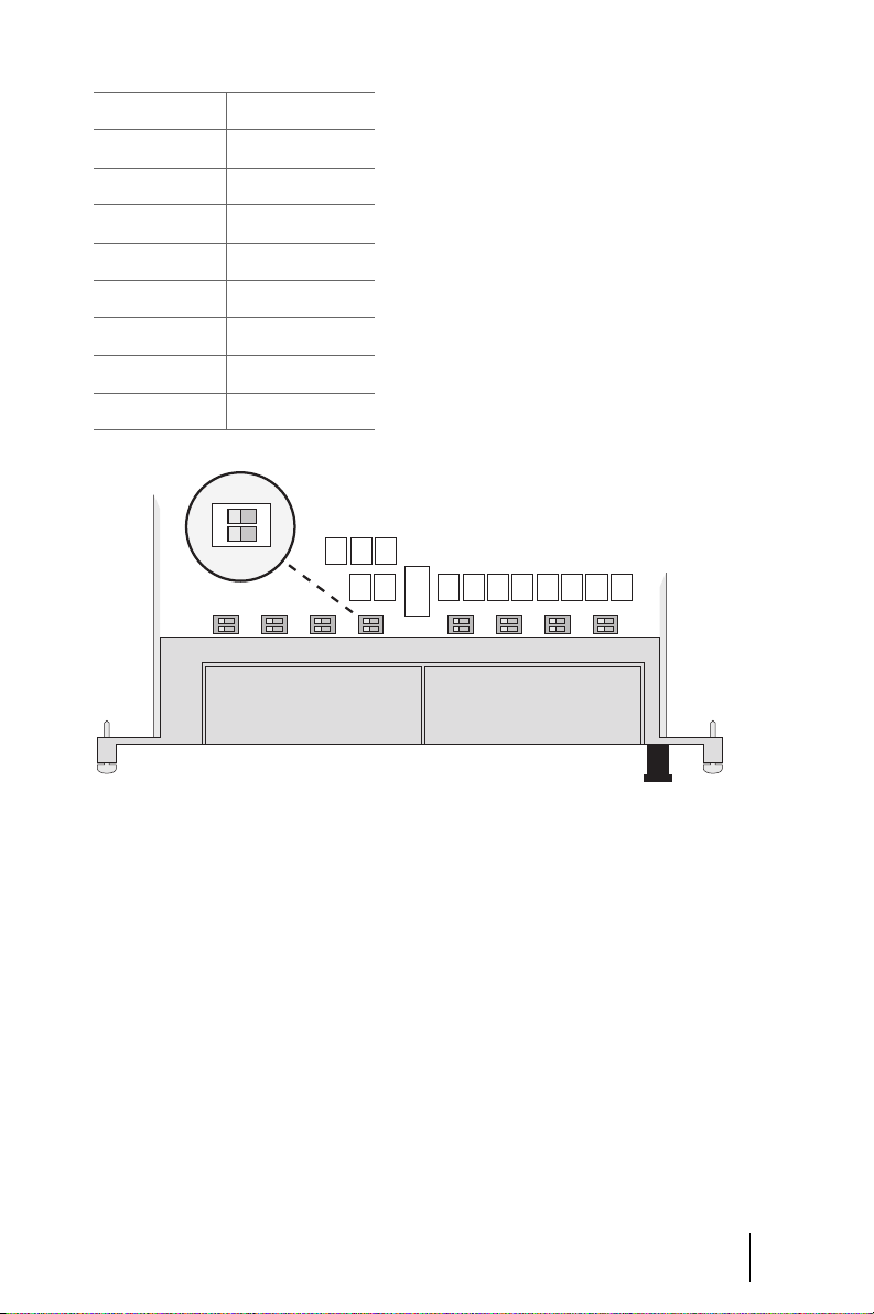
Each interface card has 16 DIP
switches (S1 to S16, two per S
inter-
0
face). The DIP switches activate the
required terminating resistors for
the S
buses (100 ohms per S0 bus).
0
In the default setting, all terminat-
ing resistors are activated (Default:
on).
MX+S01-8: Location of DIP switches S1 to S16
Note: The following configuration
information applies to external as
well as internal S
interfaces.
0
In a typical configuration, the
OpenCom 510 will be connected to
the network termination for basic
access (NTBA) with an externally
Bus Configuration: OpenCom 510
at the End of an S
0
Bus
If a OpenCom 510 is connected at
the end of an S
resistors of the relevant S
bus, the terminating
0
interface
0
switched S
port; therefore, all ter-
0
minating resistors of the interface
card are activated in the default set-
ting.
cards must be activated.
Interfaces and Connectible Terminals S0 Ports
35
Page 38
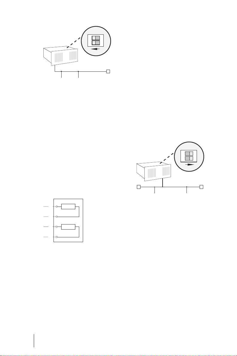
2
OpenCom 510
IAE IAE
ON
1
TR
MX+S01-8: Terminating resistors activated
One end of the S
bus is terminated
0
by the OpenCom 510; the terminating resistors must be activated (DIP
switches set to “on”).
IAE = ISDN socket (German: “ISDN
Anschluß Einheit”) or ISDN terminal.
TR = Terminating Resistor, the S
0
termination. The TR must be at the
termination of the line. This can also
be done by an appropriately wired
IAE.
1a
TR
1b
2a
TR
2b
Termination on an ISDN socket
nating resistors of the relevant S
0
terface cards must be deactivated.
1. Remove the interface card by
following the instructions in In-
stalling Interface Cards starting
on page 25.
2. The DIP switches are protected
by a plastic foil. Use a pointed
tool such as a screwdriver to
slide the DIP switches down (see
arrow in the illustration
MX+S01-8: Terminating resistors
deactivated).
2
OpenCom 510
IAE
ON
1
TRTR
IAE
MX+S01-8: Terminating resistors deactivated
Both ends of the S
bus are termi-
0
nated by terminating resistors; the
terminating resistors must be deactivated (DIP switches set to “1 2”).
in-
36
The illustration Termination on an
ISDN socket shows an IAE with inte-
grated terminating resistors.
Bus Configuration: OpenCom 510
in in the Middle of an S
0
Bus
If a OpenCom 510 is connected in
the middle of an S
bus, the termi-
0
External ISDN Ports
(S
External)
0
You can connect the OpenCom 510
to the NTBA or to a second
OpenCom 510 for PBX cascading.
S0 Ports Interfaces and Connectible Terminals
Page 39

To connect the OpenCom 510 to the
NTBA, wire pins 3, 4, 5, 6 of the NTBA
and of the OpenCom 510 1:1.
To directly connect two
OpenCom 510 systems via the external S
ports, connect the RJ45 sock-
0
ets of the systems by means of a
crossed twisted-pair cable. The distance between the two PBXs must
not exceed 1000 metres (see also
PBX Networking starting on
page 102).
TK-Anlage 1, S
12345678
87654321
ext
0
ISDN terminals can be connected to
internal S
ports by means of a
0
crossed ISDN cable. For the pin assignment of crossed ISDN cables, refer to the illustration Wirin g for direct
connection on page 37. If the terminal did not come with a suitable
ISDN cable, contact your dealer or
DeTeWe distributor.
The length of an internal S
bus ca-
0
ble must not exceed 150 m. Each internal S
prox. 3 W. The feed voltage is
bus has a power feed of ap-
0
–42 V.
TK-Anlage 2, S
(RJ 45-Buchsen)
ext
0
Wiring for direct connection
Internal S0 Ports
Up to eight ISDN terminals per bus
can be connected to the internal S
ports by means of four-wire cables.
Three of these terminals can be supplied with power from the bus; any
additional terminals will require
their own power supply. The internal
S
buses can be used for point-to-
0
multipoint connections in accordance with the DSS1 protocol (Euro
ISDN).
Interfaces and Connectible Terminals S0 Ports
0
37
Page 40

Upn Ports
Terminals Connected to
U
Ports
pn
Upn ports can be used to connect
one of the following system terminal
types:
■ RFP 21 DECT base station
■ OpenPhone 61, OpenPhone 63
or OpenPhone 65 system telephone
■ OpenPhone 52 ISDN system ter-
minal
The (corded) OpenPhone 63 and
OpenPhone 65 system telephones
can be cascaded by means of a U
adapter, which enables you to connect two OpenPhones to one U
port. For further information, refer
to the “OpenPhone 61, 63, 65” user
guide.
The RFP 21 DECT base station can be
used to connect the OpenPhone 21
and OpenPhone 25 DECT handsets.
The OpenPhone 25 has a V.24 interface for data transmissions and Internet access. Note that handsets
such as the OpenPhone 21 can also
be used in conjunction with base
stations operating with the GAP/CAP
standard.
pn
pn
Note on the MS+UPN2-8
Interface Card
U
interfaces can only be used to
pn
connect DECT base stations if the
MS+UPN2-8 has been installed in
the master system; if this card is in
the slave system, it is not possible to
connect any DECT base stations to
the card’s U
interfaces.
pn
Note on the MS+UPN1-8
Interface Card
The U
interfaces of the
pn
MS+UPN1-8 interface card cannot
be used to connect DECT base stations.
Technical Information
The Upn ports have been implemented as RJ45 sockets.
Each of the devices listed above can
be connected to the U
interface by
pn
means of a two-wire 1:1 cable. System terminals come with a suitable
cable for connection to the RJ45
socket of the interface.
A two-wire cable connected to a U
pn
port can be up to 1000 m long, provided it is a 0.6 mm twisted-pair cable.
Each U
port has a power feed of
pn
approx. 3 W. The short-circuit-proof
feed voltage is
–42 V.
38
Upn Ports Interfaces and Connectible Terminals
Page 41

DECT Base Station Connection Variants
Pin Assignment
A DECT base station can be connected to either one or two U
in-
pn
terfaces:
■ If the DECT base station is con-
nected to one U
interface, four
pn
simultaneous calls or connections can be made through the
handsets.
■ If the DECT base station is con-
nected to two U
interfaces,
pn
eight simultaneous calls or connections can be made through
the handsets.
Please note that it is not possible to
establish more simultaneous external connections than there are external B channels.
To connect a DECT base station to
two U
interfaces, you can combine
pn
two U
ports on the MS+UPN2-8
pn
interface card: U
5+6 or 7+8 (U
to U
port 1, Upn port 4 to Upn
pn
ports 1+2, 3+4,
pn
port 2 is connected
pn
port 3 etc.). Ports are combined by
setting the DIP switches on the card
accordingly. In this configuration,
the DECT base station must be connected to the first U
port of the
pn
pair by means of a 1:1 cable (system
telephone cable).
12345678
U
interface pin assignment
pn
The following table explains the U
pn
interface pin assignment.
Pin Number Assignment
1 Not used
2 Not used
3U
4U
5U
6U
7 Not used
8 Not used
a *)
pn
a
pn
b
pn
b *)
pn
*) If the DIP switches are set accordingly, the conductors of the adjacent
U
port will be connected here; use
pn
only the first U
port in this config-
pn
uration.
Setting DIP Switches
1. Remove the interface card by
following the instructions in In-
stalling Interface Cards starting
on page 25.
2. The DIP switches are protected
by a plastic foil. Use a pointed
tool such as a screwdriver to
slide the DIP switches to the
Interfaces and Connectible Terminals Upn Ports
39
Page 42
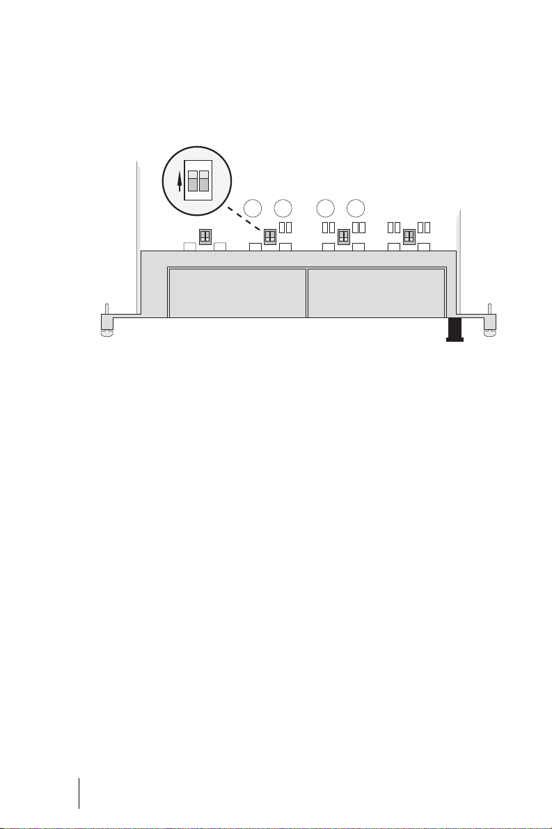
right (see arrow in the illustration Location of the DIP switches
on the MS+UPN2-8 interface card
on page 40).
ON
2
1
Location of the DIP switches on the MS+UPN2-8 interface card
a/b Ports
40
Terminals Connected to
■ external voice mail systems,
a/b Ports
■ external intercom systems.
a/b ports can be used to connect analogue terminals, e.g. apparatus for
speech and data communications
using pulse or DTMF dialling, e.g.:
■ analogue telephones,
■ G3 fax machines,
■ (external or internal) analogue
modems,
■ external music-on-hold devices,
a/b Ports Interfaces and Connectible Terminals
Please note: Observe the following notes on connecting analogue
terminals. Terminals that do not satisfy the technical requirements for
connection with the OpenCom 510
may cause damage to the communications system!
Analogue Telephones
If analogue telephones are to be
connected, we recommend devices
that support dual-tone multi-fre-
Page 43

quency (DTMF) dialling as it is not
possible to use the additional features of the OpenCom 510 with
pulse dialling telephones.
Modems
The maximum transmission rate for
analogue modems is 33.6 kbits/s
(V.34+).
Music on Hold
A suitable external device for music
on hold is the Genius 2000, manufactured by Speech Design. If you are
not using an external MoH device,
the OpenCom 510 offers an internal
MoH feature: You can change the
MoH melody in the SYS Configura-
tion: Components menu of the Con-
figurator. For further information,
refer to the online help.
Please note: For external music
on hold, use only devices with an input impedance of 600 ohms, floating
connection. An incorrect input impedance can cause irreparable damage to
the OpenCom 510!
The external voice mail system can
be connected to internal a/b ports as
well as to internal S
ports. For both
0
port types the voice mail system can
activate the notification for system
terminals with the code procedures
*68 resp. #68.
Intercom System (for a/b)
The intercom systems “DoorLine
T01/02” and “DoorLine T03/04” of
the german Telekom’s division
T-Com can be connected via the
“DoorLine M06” to any a/b port. The
“Doorline” module provides the actor for the door opener contact.
Observe the following for connection and use of the intercom system:
■ The intercom system and the
“Doorline” module should be set
to their factory settings.
■ In the PBXConfiguration:
Ports: a/b: Change menu in the
Configurator, select Doorline
under Type.
Voice Mail
If you are using an external voice
mail system, it must be capable of
handling the number of digits used
for internal telephone numbers, e.g.
five digits if you have configured
five-digit internal numbers. We rec-
■ The “Doorline” intercom system
has a number of bell keys to
which you can assign different
call numbers in the
PBX Configuration: Ports:
Doorline menu in the Configu-
rator.
ommend the following Speech Design products: Memo 200/300/400
or Memo 200-A/300-A/400-A.
■ You can call the “Doorline” inter-
com system by entering the
code procedure
*102.
Interfaces and Connectible Terminals a/b Ports
41
Page 44

■ The “Doorline” actor can be op-
erated only when the speech
channel is open at the same
time.
Pin Assignment
12345678
■ The “Doorline” intercom system
can be connected to any a/b
port. However, you can use only
one “Doorline” with the
OpenCom 510.
For details on installing and configuring the “Doorline” intercom system, refer to the product user guide.
The intercom system should be installed by qualified personnel only
as sensor/actor contacts will need to
be connected for this procedure.
Technical Information
The a/b ports have been implemented as RJ45 sockets. Each of the
devices listed above can be connected to the a/b inter face by means
of a two-wire 1:1 cable.
A two-wire cable connected to an
a/b port can be up to 6500 m long,
provided it is a 0.6 mm twisted-pair
cable, or up to 3000 m if a 0.4 mm
twisted-pair cable is used.
a/b interface pin assignment
The following Table explains the a/b
interface pin assignment.
Pin Number Assignment
1 Not used
2 Not used
3 Not used
4 Channel a
5 Channel b
6 Not used
7 Not used
8 Not used
42
The 50 Hz/40 V AC ringing voltage of
the eight interfaces is supplied by
the interface card.
a/b Ports Interfaces and Connectible Terminals
Page 45

PCM Port
The PCM port on the MC+1-3 central
control module is used to cascade
two PBXs.
Cascaded PBXs must be connected
by means of a twisted-pair cable
with RJ45 plugs. T his cabl e tran smits
voice data as well as administration
data between the PBXs.
LAN Port
The LAN port (Ethernet interface) on
the MC+1-3 central control module
allows the integration of the
OpenCom 510 into a company LAN
(Local Area Network) with the use of
a 10-Mbit hub or switch. In such a
configuration, the OpenCom 510
can, for example, act as an IP router
for establishing Internet connections.
The Ethernet interface supports
transmission rates of 10 Mbits/s and
100 Mbits/s in half duplex or full duplex mode. The transmission rate
and mode are selected automatically
(Auto Sensing function).
A LAN cable (twisted-pair in accordance with 10BaseT or 100BaseTX)
must not be longer than 100 m. Safe
operation with 100 Mbits/s requires
All eight pins of the cable must be
wired 1:1. Connect the cable to the
PCM port of the MC+1-3 central control module of each of the two PBXs.
The shielded CAT-5 cable must not
be longer than 50 centimetres.
For further information, refer to PBX
Cascading starting on page 98.
the use of category 5 cables and
sockets. Use a shielded Ethernet
cable (STP cable, Shielded Twisted
Pair cable).
DSL
External DSL modems can be connected via the LAN port. This requires the use of an external switch
or hub which connects the output of
the DSL modem (NTBBA) to the LAN
port of the OpenCom 5 10. The router
will then convert the PPPoE protocol
to the TCP/IP protocol of the LAN.
The DSL modem is connected by
means of a crossed twisted-pair cable. Alternatively, you can use a
switchable port on the hub, which is
usually marked with an “X”.
Interfaces and Connectible Terminals PCM Port
43
Page 46

OpenCom
S0Net
TCP/IP &
S
0
PPPoE
Hub
DSL & Uk
Splitter
DSL
DSL
Modem
TAE
0
DSL
NTBA
Uk
0
Crosslinked twisted pair cable
PPPoE
Network connection of the OpenCom via ISDN and DSL
Service PC
The Ethernet interface can also be
used to connect a service PC using a
crossed Ethernet cable.
COM Port
PC
TCP/IP
Net
44
The COM port (V.24-1 interface) on
the MC+1-3 central control module
can be used to connect a PC for the
purpose of transmitting connection
data. Connection data can be ana-
Note: A special 10-pin cable is required for connecting apparatus to
the V.24-1 interface. Contact your DeTeWe distributor or local retailer if you
want to purchase one of these cables.
lysed in detail with the connection
data recording program OpenCount.
Pin Assignment
Please note: The COM port cable
10
must not be longer than 3 metres.
The V.24 interface uses a transmis-
12345678
V.24 interface pin assignment
9
sion rate of 19.2 kbits/s.
COM Port Interfaces and Connectible Terminals
Page 47

The following Table explains the V.24
interface pin assignment.
Pin Number Assignment
1GND (EED)
2 Not used
3DTR
4CTS
5TXD
6RTS
7RXD
8DSR
9DCD
10 Not used
Interfaces and Connectible Terminals COM Port
45
Page 48

Accessories and Adapters
The OpenPhone 63 and
OpenPhone 65 system telephones
have one or two slots on the rear for
various adapters and other accessories. Further information on installing and operating these add-ons can
be found in the “OpenPhone 61, 63,
65” user guide under “Add-ons (with
& without an Adapter)”.
In the following you will find technical details on the add-ons and a list
of compatible accessories.
Upn Adapter
The Upn adapter is an adapter with a
U
port for connecting another
pn
OpenPhone61, 63, 65 system telephone and a socket for an extra
plug-in power supply.
Weight: 70 g
Dimensions: 73 x 60 x 30 mm
Power consumption: max. 195 mW
Cable length: max. 30 m
Please note: The U
may be used only for connecting the
system terminals listed above. The
U
extension cable must not exceed
pn
30 m in length and must not be used
outdoors.
adapter
pn
Note: An extra plug-in power supply is required to operate combinations of equipment with a power consumption that exceeds the power
output of the U
pn
ports.
a/b Adapter
You can use an a/b adapter to connect analogue terminals to the
OpenPhone 63 and OpenPhone 65
system telephones.
Connecting an a/b adapter will result in exceeding the feed performance of the U
the range. Therefore a plug-in power
supply must be additionally connected to the a/b adapter.
Note: Please use the plug-in power
supply with the product code
4505759. The plug-in power supply
for use in the UK has the product code
4510694.
Weight: 70g
Dimensions: 73 x 60 x 30 mm
Power consumption: max. 160 mW
Cable length: max. 3 m
port, regardless of
pn
Audio Adapter
46
The audio adapter is an adapter extension with four different ports for
external audio and signalling devices.
Accessories and Adapters
Page 49
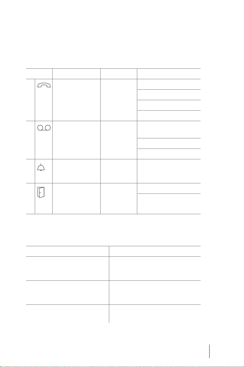
Weight: 70g
Dimensions: 73 x 60 x 30 mm
Power consumption: max. 260 mW
(with relay active).
Audio Adapter Pin Assignment
Port Used for Socket Assignment
1Ear cap,
second handset,
headset,
active speaker or microphone
2 Recording device; relay
contact generates signal for starting and
stopping recording.
3 Not used on
OpenCom 510
4 Door display RJ-11 or
Electrical Data of Ports
Port Connection Values
Microphone,
microphone of second handset,
headset microphone
RJ-10
(4-pin
West ern
socket)
Stereo jack,
3.5 mm
Round power
socket
(4 mm)
RJ-12
(6-pin
Western socket)
Electret microphone
Typical sensitivity: 10 mV/Pa
Power feed: I < 300µA at 1.5V
1: microphone -
2: speaker +
3: speaker -
4: microphone +
1 (GND): recording
signal, relay contact 1
2 (peak): recording signal +
3 (ring): relay contact 1
-
4, 5: relay contact 2
1, 2, 3, 6: NC
Ear cap,
loudspeaker of second handset,
headset, headset loudspeaker
Active speaker Max. output voltage: 1 V
Typical impedance: 150 ± 30 ohms
Typical sensitivity: 94 dB/1 mW
(0 dB = 20 µPa)
at input impedance > 10 kohms
Accessories and Adapters
rms
47
Page 50

Electrical Data of Ports
Port Connection Values
Recording device audio input Typical input sensitivity: 0.24 mV
(microphone level)
Recording device start/stop
(relay contact 1)
Door display
(relay contact 2)
Max. switching voltage: 50 VDC/29 V AC
Max. switching current: 1 ADC/0.7 A AC
Max. switching voltage: 50 VDC/29 V
Max. switching current: 1 ADC/0.7 A AC
Approved Devices / Approved Accessories
Please note: Only the following,
recommended accessories may be
connected to the audio adapter. The
cable to the door display must not be
run outdoors.
The following devices are recommended:
Type Manufacturer, Product Designation
Headset: GN-Netcom, Profile binaural (1869-00-03)
GN-Netcom, Profile 3-in-1 (1866-00-04)
Headset adapter cable: GN Netcom, QD cable (quick coupling), smooth,
Mod 4 (8800-00-01)
Second handset Siemens, L30351-F600-A366
AC
48
Handset DeTeWe, OpenPhone 60
Microphone: Winfinity, 4511326 / H 282-18
Loudspeaker: Siemens, L30460-X1278-X
Recording device: No recommendation
Accessories and Adapters
Page 51

Device Combinations
You can use the following power values to calculate the power consumption of combined equipment:
■ U
adapter: 195 mW
pn
■ Audio adapter: 260 mW
■ a/b adapter: 160 mW
(must be combined with a plugin power supply!)
■ OpenPhone 61: 1,000 mW
■ OpenPhone 63: 1,025 mW
These symbols are used in the following tables:
● This combination is possible.
❍ Reduced tone ringing, open listen-
ing and hands-free talking volume
possible.
Configurations without
Plug-in Power Supply
(Range up to 500 m)
The following table shows examples
of equipment combinations for
which the maximum power consumption of 2.4 W is not exceeded.
■ OpenPhone 65: 1,140 mW
■ Up to three add-on keypads:
330 mW
Basic Unit: OpenPhone 63
Add-ons Second Terminal Power
Audio adapter U
–––– 1025 mW
●
–
–
–
adapter Up to 3 keypad
pn
modules
– – – 1285 mW
●
●
– OpenPhone 61 2220 mW
– OpenPhone 63
2245 mW
without adapter
●
– OpenPhone 65
2360 mW
without adapter or
keypad module
Accessories and Adapters
49
Page 52

Basic Unit: OpenPhone 65
Add-ons Second Terminal Power
Audio adapter Upn adapter Up to 3 keypad
modules
– – – – 1140 mW
––
●
–
–
–
–
●
●
❍
●
●
– 1470 mW
– 1730 mW
– OpenPhone 61 2335 mW
– OpenPhone 63
2360 mW
without adapter
– OpenPhone 65
2475 mW
without adapter or
keypad module
50
Configurations without
Plug-in Power Supply
(Range 500 to 1000 m)
The following table shows examples
of equipment combinations for
which the maximum power consumption of 2.2 W is not exceeded.
Basic Unit Add-ons Power
Audio adapter U
OpenPhone 63
●
OpenPhone 65 – –
●
Accessories and Adapters
adapter Up to 3
pn
keypad modules
– – 1285 mW
●
–
●
1470 mW
1730 mW
Page 53

Configurations with
Plug-in Power Supplies
The following table shows examples
of equipment combinations operating with additional power from a
plug-in power supply.
Basic Unit: OpenPhone 63
Add-ons: Second terminal
Up to 3
keypad
modules
Audio
adapter
U
adapter
pn
and plug-in
power
supply
OpenPhone 61 OpenPhone 63
without
adapter
OpenPhone 65
without
adapter and
with 1 keypad
module
● ●
● ●
● ●
Basic Unit: OpenPhone 65
Add-ons: Second terminal
Up to 3
keypad
modules
Audio
adapter
U
adapter
pn
and plug-in
power supply
OpenPhone 61 OpenPhone 63
without
adapter
OpenPhone 65
without
adapter and
with 1 keypad
module
● ● ●
● ● ●
● ● ●
● ● ● ●
● ● ● ●
● ● ● ●
Accessories and Adapters
51
Page 54

Modules
This chapter provides detailed technical information on the modules
which can be installed in the
OpenCom 510. You will find information on their respective fields of application, along with technical and
operational information and notes
on indicators.
The modules fulfil the following
tasks:
■ Power supply units (max. 2) pro-
vide the OpenCom 510 with
power.
■ A central control module controls
the entire system. This module
also houses the memory card
(CompactFlash) for storing data.
■ Interface cards are used to con-
nect the OpenCom 510 to the
telecommunications network
(or to another communications
system) and to connect terminals.
A number of interface cards are
available for these tasks. Depending on the interface card’s
functions, it may also be referred
to as a trunk module or as a subscriber module.
Please note: When installing
modules, always observe the Notes
on Safety starting on page 17!
52
For detailed information on installing modules, refer to the chapter In-
stalling Modules starting on page 22.
Modules
Page 55

Module Naming Conventions
The names of the modules indicate
the module type and functions:
Mx+y1-z
Abbr. Meaning
MModule
x Indicates the module type as
follows:
CControl
SSubscriber
TTrunk
X Subscriber/Trunk
PS Power Supply
+ Character used to divide the
product name
y Indicates the interface type as
follows:
A Analogue interface
UPN U
S0 S
S2M S2M interface
1 Module generation
- Character used to divide the
product name
zNumber of interfaces
interface
pn
interface
0
Modules Module Naming Conventions
53
Page 56

Overview of Available Modules
The following table provides an
overview of modules available for
the OpenCom 510:
Name Description Page
MPS+1-AC Power supply with AC/DC converter 55
MC+1-3 Central control module with three interfaces 57
MT+S2M 1-1 Trunk module with one S
networks or for cascading two PBXs
MX+S01-8 Trunk or subscriber module with eight S
external (trunk) or internal (subscriber) connections
MS+UPN1-8 Subscriber module with eight U
digital terminals (ISDN terminals, system telephones); does
not support DECT base stations
MS+UPN2-8 Subscriber module with eight Upn interfaces for connecting
digital terminals (ISDN terminals, system telephones) and
DECT base stations
interface for connecting to di gital
2M
interfaces for either
0
interfaces for connecting
pn
60
63
65
66
54
MS+A1-8 Subscriber module with eight a/b interfaces for connecting
analogue terminals
The name of the module and the interface type are printed on the front
MX+S01-8
68
of the modules. The following illustration shows the printing on the
MX+S01-8 interface card.
S0 1S0 2
Detail: Printing on the front of an
MX+S01-8 interface card
Overview of Available Modules Modules
Page 57
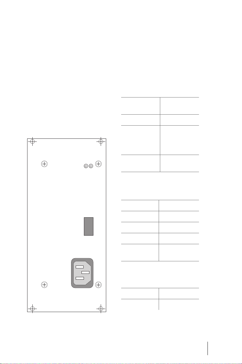
MPS+1-AC
Field of Application
The MPS+1-AC power supply unit
supplies power to the first six slots
(1 to 6) of the OpenCom 510. The
MPS+1-AC converts the output voltages (220 V/110 V) output voltages
into a DC voltage (+3.3 V and
–42 V).
If the remaining slots (7 to 12) are to
be used, a second MPS+1-AC power
supply unit will need to be installed.
MPS+1-AC
Technic al Data
The following data refer to the supply of power to the first six slots.
Input Voltage
Rated voltage 230 V via standard
IEC connector
Voltage range
Rated current
Efficiency at rated
load
+3.3 V Output Voltage
Rated voltage
Voltage range
Rated current
95 V to 275 V
2.0 A at 115 V
1.0 A at 230 V
0.9 A at 275 V
> 80 %
+3.3 V
+3.2 V... +3.4 V
10.0 A
Current limitation
Short-circuit Continuous short-
–42 V Output Voltage
Rated voltage
Voltage range
12 A to 15 A
circuit protection
–42 V
–40 V... –44 V
MPS+1-AC: Front view
Modules MPS+1-AC
55
Page 58

–42 V Output Voltage
Rated current
Current limitation
Short-circuit Continuous short-
4.0 A
4.4 A to 5.5 A
circuit protection
Indicators
There are two LEDs on the front of
the MPS+1-AC power supply unit.
The LEDs indicate the following:
■ Left: If the left LED is constantly
lit up green, the output voltage
is +3.3 V.
■ Right: If the right LED is con-
stantly lit up green, the output
voltage is –42 V.
The LEDs only indicate that the voltage is present. They do not say anything about the voltage quality.
In the event of a power failure, the
power supply unit will generate a
power failure signal.
56
Operational Information
The MPS+1-AC power supply unit
will be ready for operation as s oon as
it has been plugged into the designated slot (see Slots starting on
page 22).
The mains voltage of 230 V is drawn
through the standard IEC connector.
The output voltages are fed to the
BPV+1-12 backplane through the
96-pin spring contact strip (see
Backplane starting on page28).
MPS+1-AC Modules
Page 59
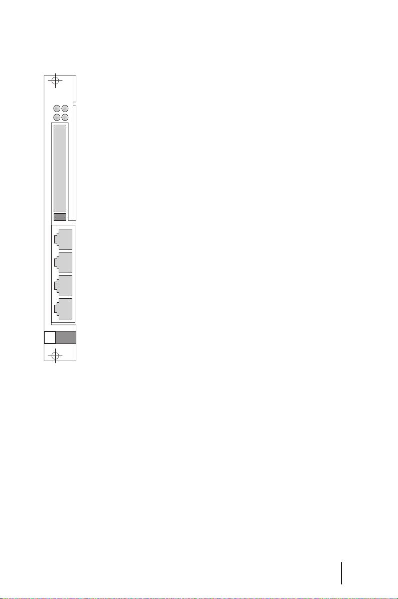
MC+1-3
MC+1-3
PCMEthernet
These are standard external Ethernet
(1x) and V.24 (2x) interfaces as well
as internal PCMV, PCMH and CompactFlash slot interfaces.
Technical Information
■ The MC+1-3 central control
module is powered by the
group 1 power supply unit.
■ The MC+1-3 central control
module has a plug-in card
(MSUB-MRAM) with 128 Mbytes
of main (random access) memory.
V.24-1
Please note: This plug-in card
must not be exchanged by service
V.24-2
personnel. In the event of a malfunction, the entire MC+1-3 central control module must be sent in for repair.
■ The MC+1-3 central control
MC+1-3: Front view
module has a CompactFlash slot
(MSUB-MFL, PCMCIA interface)
for CompactFlash cards. The fol-
Field of Application
The MC+1-3 module is the central
control module of the
OpenCom 510. It can be installed in
slot 0 only (at the left end in the 1-12
frame; see Slots starting on
page 22).
In addition to the control function,
the MC+1-3 central control module
provides a number of interfaces.
lowing data are stored on the
CompactFlash card: the
OpenCom 510 firmware, the system terminal software, the configuration data and all customer
data such as audio files for the
internal voice mail system.
Note: Only licensed cards may be
used. These are currently (May 2004)
special 256-Mbyte cards by SanDisc.
Modules MC+1-3
57
Page 60

Contact your DeTeWe distributor or
local retailer if you want to purchase
one of these cards.
■ In cascaded configurations, mas-
ter and slave systems are connected via the PCM port (RJ45
socket).
■ In cascaded OpenCom 510 con-
figurations, the slave system requires an MC+1-3 central control module of its own.
■ In cascaded OpenCom 510 con-
figurations, a CompactFlash c ard
must be installed in the master
system; it is not necessary to install one of these cards in the
slave system.
for frame coding (PBX Cascading
starting on page 98).
■ The Ethernet port (10/100
Mbits/s) can be used to connect
the OpenCom 510 to the LAN.
■ The V.24-1 interface can be used
to connect additional apparatus,
e.g. a computer for analysing
call charges.
For information on the V.24 interface pin assignment, refer to
COM Port starting on page 44.
Indicators
There are four LEDs on the front of
the MC+1-3 central control module.
58
■ In cascaded configurations, the
central control modules use the
PCMV interface to exchange system signals. The PCMV interface
MC+1-3
1
2
3
4
provides the system clock signals, access to the 16-Mbit/s
PCM highway, and a 2-Mbit/s
LAN.
MC+1-3: LEDs
■ In cascaded configurations, the
S1 and S2 DIP switches are used
LED 1: Flashing yellow New software is being loaded onto an interface card
(the corresponding interface card’s indicator will be
constantly red).
LED 2: Constantly green The central control module is operational (flickering
is normal).
Flashing green/yellow The system software (firmware) is starting up.
The LEDs indicate the following:
MC+1-3 Modules
Page 61

Flashing yellow The booter is reloading.
Constantly yellow The system is booting.
Constantly red System fault
LED 3: – Not used
LED 4: Constantly green An Ethernet connection has been established.
Operational Information
If you need to exchange the central
control module, shut down the system first! The OpenCom 510 must be
disconnected from the mains supply
(see Installing the Central Control
Module starting on page 23).
Do not pull the CompactFlash card
during operation as this may cause
data to be lost!
A MC+1-3 central control module installed in a master system provides
the following central resources:
■ 3 three-party conferences
■ 6 DTMF transmitters
■ 10 DTMF receivers
■ 1 Music On Hold
■ 32 HDLC controllers for RAS, ISP
and DECT data.
If the MC+1-3 central control module is removed from a cascaded PBX,
the entire system will become inoperative.
Modules MC+1-3
59
Page 62
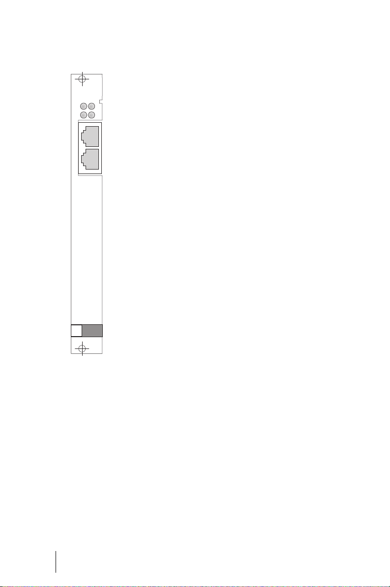
MT+S2M1-1
MT+S2M1-1
The MT+S2M1-1 interface card can
be installed in any of the slots (1 to
12) of the OpenCom 510 (see Slots
starting on page 22).
S2M-42V
MT+S2M1-1: Front view
Field of Application
The MT+S2M1-1 interface card provides one ISDN S
interface for con-
2M
necti ng the OpenCom 51 0 either to a
primary rate access or to a second
PBX (ISDN point-to-point connection).
Technical Information
■ The MT+S2M1-1 interface card
can also be installed in a slave
system.
■ A maximum of four MT+S2M1-1
interface cards can be configured in the entire system.
■ No settings need to be made on
the MT+S2M1-1 interface card.
■ The MT+S2M1-1 interface card
runs on software acquired from
the system. After the card has
been installed it will automatically load the required software.
■ The maximum range is 300 m.
■ The short-circuit-proof feed
voltage is
–42 V/7 W.
60
MT+S2M1-1 Modules
Page 63

Pin Assignment
The following table shows the pin
assignment for the RJ45 connector
of the interface (labelled “S2M”; see
the illustration MT+S2M1-1: Front
view on page 60):
Pin Number Assignment
1IN a
2IN b
3 Not used
Indicators
There are four LEDs on the front of
the MT+S2M1-1 interface card.
MT+S2M1-1
1
2
S2M-42V
3
4
4OUT a
5OUT b
6 Not used
7 Not used
8 Not used
The following table shows the pin
assignment for the RJ45 connector
of the power feed cable (labelled
“–42 V”; see the illustration
MT+S2M1-1: Front view on page 60):
Pin Number Assignment
1 Not used
2 Not used
3
40 V
50 V
6
–42 V
–42 V
MT+S2M1-1: LEDs
7 Not used
8 Not used
Modules MT+S2M1-1
61
Page 64

The LEDs indicate the following:
LED 1: Constantly yellow At least one connection established through the in-
terface card is active.
LED 2: Constantly green The interface card is operational; the slot has been
activated (flickering is normal).
Flashing yellow The interface card is ready, but the slot has not been
activated or the interface card has not been configured yet.
Constantly red New software is being loaded onto the interface
card. If the LED lights up red for an extended period
of time, there may be a fault.
LED 3: Constantly green The interface card is providing the system clock sig-
nal (indicated only in the master system and only on
an interface card).
LED 4: – Not used
Operational Information
The MT+S2M1-1 interface card can
be exchanged during operation, i.e.
without powering down the system.
However, the slot must first be deactivated in the Configurator in the
web console (see Installing Interface
Cards starting on page 25).
62
If the MT+S2M1-1 interface card is
being used in the master system of a
cascaded configuration, it can provide the system clock signal. Unless
otherwise specified, the system automatically selects an S
card as
2M
the clock signal source. For further
information, refer to PBX Cascading
starting on page 98.
MT+S2M1-1 Modules
Page 65

MX+S01-8
Field of Application
The MX+S01-8 interface card provides eight 8 S
interfaces which can
0
be used for either external connections, i.e. to connect the
OpenCom 510 to a digital network
(PSTN, Public Switch Telephony Network), or internal connections, i.e. to
connect digital terminals (ISDN telephones, ISDN fax machines etc.) to
the OpenCom 510.
The MX+S01-8 interface card can be
installed in any of the slots (1 to 12)
of the OpenCom 510 (see Slots starting on page 22).
Technical Information
■ The MX+S01-8 interface card
can also be installed in a slave
system.
■ DIP switches S1 to S16 can be
used to activate a 100-ohm terminal resistor (default: ON).
For further information, refer to
Termination starting on page 35.
■ The power failure circuit can be
activated by means of DIP
switches S17 to S20 (default:
off). If activated, the system will
connect the first S
with the eighth S
interface
0
interface in
0
the event of a power failure; provided the system has been con-
figured accordingly, external
calls can be made using an
emergency telephone.
For further information, refer to
Power Failure starting on
page 31.
■ All eight S
interfaces can be
0
configured either as subscriber
(internal) interfaces or as trunk
(external) interfaces.
For further information, refer to
S0 Ports starting on page 34.
■ If the MX+S01-8 interface card is
being used in the master system
of a cascaded configuration, it
can provide the system clock signal.
For further information, refer to
PBX Networking starting on
page 102.
■ The MX+S01-8 interface card
runs on software acquired from
the system. After the card has
been installed it will automatically load the required software.
Pin Assignment
For information on the S
interface
0
pin assignment, refer to S0 Ports
starting on page 34.
Modules MX+S01-8
63
Page 66

Indicators
There are four LEDs on the front of
the MX+S01-8 interface card.
MX+S01-8
1
2
S0 1S0 2
3
4
MX+S01-8: LEDs
The LEDs indicate the following:
LED 1: Constantly yellow At least one connection established through the in-
terface card is active.
LED 2: Constantly green The interface card is operational; the slot has been
activated (flickering is normal).
Flashing yellow The interface card is ready, but the slot has not been
activated or the interface card has not been configured yet.
64
Constantly red New software is being loaded onto the interface
card. If the LED lights up red for an extended period
of time, there may be a fault.
LED 3: Constantly green The interface card is providing the system clock sig-
nal (indicated only in the master system and only on
an interface card).
LED 4: Constantly yellow The interface card is running a combination of sub-
scriber and trunk connections, i.e. both internal and
external S
Operational Information
The MX+S01-8 interface card can be
exchanged during operation, i.e.
interfaces have been configured.
0
tivated in the Configurator in the
web console (see Installing Interface
Cards starting on page 25).
without powering down the system.
However, the slot must first be deac-
MX+S01-8 Modules
Page 67

All three protocol layers can be individually configured as master or
slave for each S
interface.
0
MS+UPN1-8
interfaces can be configured
The S
0
as DSS1-PP, DSS1-PMP or Q.SIG lines.
Field of Application
The MS+UPN1-8 interface card provides eight U
interfaces for con-
pn
necting system terminals; however,
it is not possible to connect DECT
base stations.
The MS+UPN1-8 interface card can
be installed in any of the slots (1 to
12) of the OpenCom 510 (see Slots
starting on page 22).
Technical Information
■ The MS+UPN1-8 interface card
can also be installed in a slave
system.
■ No settings need to be made on
the MS+UPN1-8 interface card.
■ The MS+UPN1-8 interface card
runs on software acquired from
the system. After the card has
been installed it will automatically load the required software.
Pin Assignment
RJ45 Connector Pin Assignment for
the MS+UPN1-8 Interface
Pin Number Assignment
1 Not used
2 Not used
3 Not used
4U
5U
6 Not used
7 Not used
8 Not used
a
pn
b
pn
Indicators
There are four LEDs on the front of
the MS+UPN1-8 interface card.
MS+UPN1-8
1
2
3
4
UPN 1UPN 2
MS+UPN1-8
Modules MS+UPN1-8
65
Page 68

The LEDs indicate the following:
LED 1: Constantly yellow At least one connection established through the in-
terface card is active.
LED 2: Constantly green The interface card is operational; the slot has been
activated (flickering is normal).
Flashing yellow The interface card is ready, but the slot has not been
activated or the interface card has not been configured yet.
Constantly red New software is being loaded onto the interface
card. If the LED lights up red for an extended period
of time, there may be a fault.
LED 3: – Not used
LED 4: – Not used
Operational Information
The MS+UPN1-8 interface card can
be exchanged during operation, i.e.
without powering down the system.
However, the slot must first be deactivated in the Configurator in the
MS+UPN2-8
Field of Application
The MS+UPN2-8 interface card provides eight U
necting system terminals and DECT
base stations.
The MS+UPN2-8 interface card can
be installed in any of the slots (1 to
12) of the OpenCom510 (see Slots
starting on page 22).
interfaces for con-
pn
web console (see Installing Interface
Cards starting on page 25).
The short-circuit-proof feed voltage
is
–42 V.
Technical Information
■ The MS+UPN2-8 interface card
can also be installed in a slave
system.
■ A maximum of 48 RFPs (Radio
Fixed Parts, DECT base stations)
can be connected to the entire
system.
66
MS+UPN2-8 Modules
Page 69

■ In order to connect RFPs, U
ports 1+2, 3+4, 5+6 or 7+8 can
be combined by setting the DIP
switches on the card accord-
pn
Pin Assignment
For information on the U
interface
pn
pin assignment, refer to Upn Ports
starting on page 38.
ingly.
Indicators
For further information, refer to
Upn Ports starting on page 38.
■ The MS+UPN2-8 interface card
runs on software acquired from
the system. After the card has
been installed it will automatically load the required software.
There are four LEDs on the front of
the MS+UPN2-8 interface card.
MS+UPN2-8
1
2
UPN 1UPN 2
3
4
MS+UPN2-8
The LEDs indicate the following:
LED 1: Constantly yellow At least one connection established through the in-
terface card is active.
LED 2: Constantly green The interface card is operational; the slot has been
activated (flickering is normal).
Flashing yellow The interface card is ready, but the slot has not been
activated or the interface card has not been configured yet.
Constantly red New software is being loaded onto the interface
card. If the LED lights up red for an extended period
of time, there may be a fault.
LED 3: – Not used
LED 4: – Not used
Modules MS+UPN2-8
67
Page 70

Operational Information
The MS+UPN2-8 interface card can
be exchanged during operation, i.e.
without powering down the system.
However, the slot must first be deactivated in the Configurator in the
MS+A1-8
web console (see Installing Interface
Cards starting on page 25).
DECT base stations can be connected
only if the interface card has been
installed in the master system of a
cascaded configuration.
Field of Application
The MS+A1-8 interface card provides eight analogue interfaces for
connecting analogue terminals.
The MS+A1-8 interface card can be
installed in any of the slots (1 to 12)
of the OpenCom 510 (see Slots starting on page 22).
Technical Information
■ The MS+A1-8 interface card can
also be installed in a slave system.
■ The MS+A1-8 interface card
supports pulse dialling as well as
dual-tone multi-frequency
(DTMF) dialling. The central receivers of the MC+1-3 interface
card are used for DTMF recognition.
■ Calling line identification pres-
entation (CLIP) is supported.
■ The consultation feature can be
selected by means of a flash key
and/or earthing key.
■ The MS+A1-8 interface card
runs on software acquired from
the system. After the card has
been installed it will automatically load the required software.
■ No settings need to be made on
the MS+A1-8 interface card.
Pin Assignment
For information on the a/b interface
pin assignment, refer to a/b Ports
starting on page 40.
Indicators
There are four LEDs on the front of
the MS+A1-8 interface card.
68
MS+A1-8 Modules
Page 71

MS+A1-8
1
2
a/b 1a/b 2
3
4
MS+A1-8
The LEDs indicate the following:
LED 1: Constantly yellow At least one connection established through the in-
terface card is active.
LED 2: Constantly green The interface card is operational; the slot has been
activated (flickering is normal).
Flashing yellow The interface card is ready, but the slot has not been
activated or the interface card has not been configured yet.
Constantly red New software is being loaded onto the interface
card. If the LED lights up red for an extended period
of time, there may be a fault.
LED 3: – Not used
LED 4: – Not used
Operational Information
The MS+A1-8 interface card can be
exchanged during operation, i.e.
without powering down the system.
However, the slot must first be deactivated in the Configurator in the
web console (see Installing Interface
Cards starting on page 25).
Modules MS+A1-8
69
Page 72
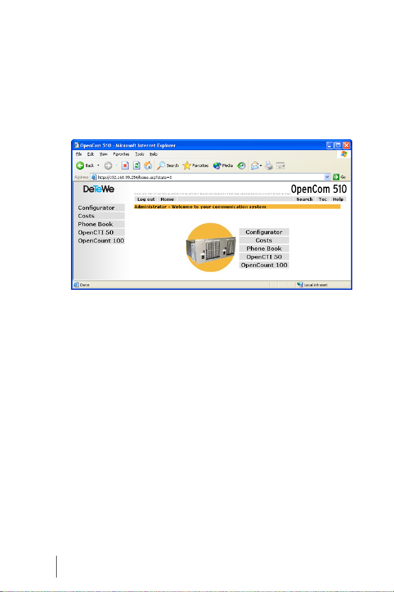
Configuration
Configuration and programming of
the OpenCom 510 is performed by
the Configurator, a special software
application integrated into the sys-
The OpenCom 510 Web console
Using the Web console, you can:
■ perform the initial configura-
tion of the OpenCom 510,
■ configure users of the
OpenCom 510 and authorise
them to use certain system services,
tem. The Configurator is operated
via the Web console, which can be
run on any PC connected to the
OpenCom 510.
■ access the OpenCom 510 tele-
phone book.
The Web console has an integrated
online help function that offers com-
prehensive information on configu-
ration and maintenance of the
OpenCom 510 (see Loading the On-
line Help starting on page 81).
70
■ carry out further
system maintenance,
■ use PC-supported telephony
functions,
■ read out call charge information,
Note: In order to use all the new
system software functions, we recom-
mend that you download the latest
software from our Web site at
http://www.detewe.com.
For the initial configuration you can
connect the PC to the OpenCom 510
Configuration
Page 73

via the Ethernet port. A COM port
can also be used. The TCP/IP network
protocol is used to set up a connection via one of these ports. You can
then open the Web console of the
OpenCom 510 and call up the Con-
figurator from there.
Note: This chapter describes initial
configuration of the OpenCom 510.
For day-to-day operation you can integrate the OpenCom 510 into a LAN
and start the Configurator from any
PC. For information on how to do this,
refer to the Configuration Examples
starting on page 86.
Brief Guide to Initial Configuration
Setting up a first connection is quite
simple with a standard Windows PC:
1. Turn off the PC. Remove all connected network cables.
2. Connect the PC network card to
the LAN port. Use a cross-wired
Ethernet cable to do this.
3. Restart the PC. If you manually
deactivated the automatic configuration of the network card
via DHCP, you must reactivate
this and again restart the computer.
4. Start the Web browser. In the
address field, enter
“http://192.168.99.254/”.
The login page of the Web console
will then open. For further details,
please refer to Configuring the
OpenCom 510 starting on page 79.
First Configuration via Serial Port
1. The serial port can also be used
as alternative access for the first
configuration.Additionally, you
require a crossed serial line
(“null modem”).Install the “occonfig” program from the system CD. To do this, you must log
on as an administrator under
Windows NT or Windows 2000/
XP.
2. Shut down the PC. Remove all
connected network leads. Connect the serial port of the PC to
the COM port of the
OpenCom 510.
3. Restart the PC. Set up an RAS
link with the icon configured on
the desktop under step 1. Enter
“Administrator” without a password as your user name.
Configuration Brief Guide to Initial Configuration
71
Page 74

4. Start the Web browser. Enter
“http://192.168.99.254/” in the
address box.
System Requirements
You will see the log-on page of the
Web console. Continue reading under Configuring the OpenCom 510
starting on page 79.
Note: If no connection can be established by following the instructions in the Brief Guide to Initial Configuration starting on page 71, refer
to the more detailed explanations below.
A normal TCP/IP-capable PC with a
Web browser is required for the initial configuration. The PC should at
least meet the following requirements:
■ IBM-compatible 200 MHz PC
■ 32 MB RAM and 50 MB of free
hard disk space
■ Microsoft Windows 95/98,
Microsoft Windows 2000/XP or
Microsoft Windows NT 4.0 operating system
■ Microsoft Internet Explorer ver-
sion 4.0 or higher, or Netscape
Communicator version 4.5 or
higher
Note: Microsoft Internet Explorer is
already installed in current versions
of the Microsoft Windows operating
system. If required, a Web browser
can be installed from the system CD
delivered with the OpenCom 510.
In addition, the selected type of connection requires further system
components that you may have to
install on your PC. The driver software is normally supplied with the
hardware, and the appropriate version should be available for your operating system. You will find the system software on the installation CD
of your operating system.
For connection on the V.24 port
(COM port) you need:
■ Hardware: one free serial port
(RS-232, V.24) and a serial cable
(SUBD9). System software: serial port driver and TCP/IP protocol software
■ Driver software: RAS adapter
software for installation on the
service PC (is included on the
CD)
For connection by network card you
need:
72
System Requirements Configuration
Page 75

■ Hardware: network card with
10BaseT port and RJ-45 network
cable (crossover twisted pairs or
connection via a hub)
■ Software: network card driver
and TCP/IP protocol software
Configuration under Windows
Before beginning initial configuration, install the necessary hardware
and matching driver software on the
PC. Follow the installation instructions supplied with the hardware. In
many cases, the TCP/IP system software is installed together with the
driver software for the hardware.
When you have installed the driver
software, proceed as follows:
Note: The following steps are not
necessary under Windows 2000/XP. If
possible, use a network card connection as network cards are easier to
configure and feature higher data
transfer rates. For more information
please read Connection by Network
Card (LAN) star ting on page 75
1. Open “Network Settings” in the
Control Panel of your PC. To do
this, you select the item “Settings > Control Panel” from the
Start menu and double-click on
the “Network” icon. Under Windows NT, select the “Protocols”
tab.
2. Check the list of installed components to see whether the TCP/
IP protocol is present. If necessary, install TCP/IP by clicking on
the “Add” button.
3. Select “TCP/IP” from the “Protocol/Microsoft” folder and confirm your entry with “OK”.
4. Then follow the installation instructions displayed.
Depending on the type of connection (network card or V.24) you select, note the following when installing the driver and system software.
Connection on Serial Port (V.24)
The required components are normally ready installed together with
the operating system. In this case,
you can easily configure the connection to the OpenCom 510 by using
the program “occonfig”:
Note: Under Windows NT or Windows 2000/XP you must log on as an
administrator.
Configuration Configuration under Windows
73
Page 76

1. Insert the system CD supplied
along with the OpenCom 510.
The CD starts automatically if
your PC is configured accordingly. Otherwise select “Run” in
the Start menu. Use the
“Browse” button to find the
“cd_start.exe” program on the
CD. Confirm your entry with
“Open” and “OK”.
2. Select the “Software, installation
program for RAS network link”
option from the start mask. Click
on “OK” to install the modem
driver.
3. In the dialogue that follows, select a serial por t and confirm this
with “OK”.
2. Double-click on the OpenCom
desktop icon created with the
“occonfig” program.
3. In the dialogue which follows,
enter the user name and password valid for the OpenCom 510
user account being used. For the
initial configuration, log on under the user name “Administrator” without giving a password.
Clear any entries in the “Domain” box and confirm this with
“OK”.
When the connection is established, all necessary IP address
parameters will be transmitted
by the OpenCom 510 using the
PPP protocol and automatically
set for the direct PC link.
74
After restarting your computer, you
will find an icon for the connection
to the OpenCom 510 on your desktop.
Note: If this procedure cannot be
completed properly, refer to the section entitled Notes on Configuring the
Serial Port on page 75.
Establishing a Remote Data
Transfer Connection
1. Connect the serial port of the PC
to the OpenCom 510 COM port.
You will require a suitable connector cable.
Configuration under Windows Configuration
4. Once set-up of the connection is
confirmed, you can continue
with Testing the Setup starting
on page 76.
Note: It is not possible to operate a
network card and a remote data
transfer connection for the same network address range simultaneously.
For this reason you must temporarily
deactivate the network card when
you want to establish a remote data
transfer connection. To do this, open
the “System” icon in the Control Panel
and deactivate the network card in
the “Devices” tab. If the PC is configured via DHCP, you can instead also
disconnect the PC from the LAN and
reboot it.
Page 77

Notes on Configuring the Serial Port
Installing the RAS under
Windows NT 4.0
A serial port is automatically detected when the PC boots and the
corresponding system software is installed. The TCP/IP connection to the
OpenCom 510 is established by
means of additional system software: the RAS adapter software and
the serial port driver.
Tip: The serial port that you use is
operated with the parameters
57,600 baud, 8 data bits, 1 stop bit,
no parity and no hardware data flow
control.
Note: The RAS network is always
installed under Windows 2000/XP
and cannot be uninstalled. The following section is only relevant for users of old Windows versions.
Installing the RAS Network under
Windows 95 or Windows 98
1. Open the Control Panel and double-click on the “Software” icon.
1. Open the Control Panel and double-click on the “Network” icon.
2. Select the “Services” tab and
click on the “Add” button.
3. Select “Remote Access Service”
from the list and confirm with
“OK”.
4. To conclude installation of the
RAS, the RAS “Properties” dialogue is displayed. Select the
driver “OpenCom Modem” that
was created on the first start of
the program “occonfig” and confirm this with “OK”.
5. Confirm the configuration with
the “Continue” button and close
the network settings.
Note: If you have installed an operating system update earlier (Service
Pack), install this again after installation of the RAS.
2. Click on the “Windows Setup”
tab and double-click on the item
“Communications”.
3. Tick the check box next to the
component “RAS Network” and
confirm your entry with “OK”.
Configuration Configuration under Windows
Connection by Network Card (LAN)
First-time configuration of the
OpenCom 510 is also possible by a
network card, providing this is already installed on the PC, of course.
When the driver software for a network card is installed, the necessary
75
Page 78

system software for the TCP/IP protocol is installed at the same time.
During this process you should activate the automatic assignment of IP
addresses by the DHCP protocol.
Note: For initial configuration, it
may be wise not to connect the
OpenCom 510 to an existing LAN in
order to eliminate conflicts with an
existing DHCP server.
If the PC has been operating in a network to date, you should activate the
automatic assignment of an IP address.
1. To do this, you select “Settings >
Control Panel” in the Start
menu. Double-click on the “Network” icon. Under Windows NT
select the “Protocols” tab. Under Windows 2000/XP right click
on the “LAN Link” icon. Select
“Properties”.
2. Double-click on the item “TCP/IP
Protocol > Network card”. Activate the option “Obtain an IP address from a DHCP server” in the
“Properties” dialogue. Gateway
or DNS entries must be deactivated.
Note: Changes to the Gateway and
the DNS configuration are made by
DHCP.
Establishing a Network
Connection
1. Connect the PC network card to
the OpenCom 510 network port.
To do this, use either a crossover
twisted-pair network cable or
connect the OpenCom 510 via a
hub.
2. Restart your PC. During the system start, all necessary IP address parameters will be transmitted by OpenCom 510 via
DHCP and automatically set for
the network card.
Note: If the PC has been operating
under Windows NT in a network with
a Windows NT domain, you will not
be able to log on to the domain. So
log on to the PC domain as the local
user “Administrator”.
3. Continue reading under Te st i ng
the Setup starting on page 76.
Testing the Setup
Subsequent to establishment, test
the TCP/IP connection between the
OpenCom 510 and the PC.
1. Select the item “Run” in the
Start menu. Enter the command
“ping host.domain” or
“ping 192.168.99.254” in the
“Open” box.
2. Confirm this with “OK”.
Tip: To find the IP address of the
Web console, enter
on a connected system telephone.
*182
76
Configuration under Windows Configuration
Page 79

*183 will also show you
the network mask.
You can test the correct IP configuration under Windows 95 and Windows 98. Select the item “Run” in
the Start menu. Enter the command
“winipcfg” in the “Open” box. Confirm this with “OK”. Select the network adapter used for connection to
the OpenCom 510. The IP addresses
assigned by the OpenCom 510 on establishment of the connection will
be displayed.
Under Windows NT4, 2000 and XP
you can check the IP configuration
by entering the commands “ipconfig
-all” or “route print” in the command
prompt. The command “arp -a” produces a list of assigned IP addresses
for LAN links.
Starting the Browser
Start the installed Web browser.
When you start the Microsoft Internet Explorer for the first time, the Internet access wizard will automatically appear. Select the option “Use
existing account” and confirm this
with “OK”.
If the PC has been operating in a network or used for Internet access, it is
possible that access may be configured indirect via a proxy server. Deactivate access via a proxy server
(“Direct connection”). To do this in
the Internet Explorer, open the Internet options in the menu “Tools > Internet Options”, then select the
“Connections” tab. In Netscape Communicator, you select the command
“Edit > Settings” and then select the
section “Extended > Proxies” under
“Category”.
Note: Reset your browser’s options
for the call-up of pages to their default settings specified on initial installation of the browser.
Configuration for Linux and MacOS
All modern operating systems support the TCP/IP protocol. You can
find detailed information on setting
up hardware and software for the
Windows operating systems under
Configuration under Windows starting on page 73. In this section there
are tips on integrating Linux and
MacOS operating systems.
Configuration Configuration for Linux and MacOS
Linux
The Linux network configuration is
usually performed by the set-up program with which you install a Linux
distribution. After installation, you
will see a series of “How To's”. In
“Linux NET-3-HowTo” and “DHCP
77
Page 80

Mini-HowTo” you will find instructions on TCP/IP configuration.
For the OpenCom 510 to configure
the TCP/IP settings of a Linux system
via DHCP, you must also install the
“dhclient” package and activate configuration via DHCP in the Linux network configuration. To access the
OpenCom 510 Configurator, you
should also install Netscape Communicator 4.5 (or higher).
MacOS
The TCP/IP protocol is already integrated in the new MacOS starting
with version 7.6. For the
OpenCom 510 to configure the TCP/
IP settings of a MacOS system via
DHCP, you must set the configuration method to “DHCP Server” in the
menu “Control Panels TCP/IP”.
78
To access the OpenCom 510 Configurator, you should also install Net-
scape Communicator 4.5 (or higher)
or Microsoft Internet Explorer 4.5 (or
higher).
Configuration for Linux and MacOS Configuration
Page 81

Configuring the OpenCom 510
Preparing the Configuration
Before starting with the configuration, make sure you have the following documents at hand:
■ An overview of the ports
■ A list of the terminals to be con-
nected
■ A list of the IPEIs, if you wish to
log on DECT terminals in the secure procedure
■ A list of the users to be set up
(staff entitled to use the services
of the OpenCom 510) with their
names, departments, a nd the internal call numbers you want to
allocate to them
■ For Internet access: the Internet
service provider access data.
Data not available for first-time configuration can be updated or corrected at a later date.
Starting the Web Console
1. Start your Web browser. Enter
the OpenCom 510 IP address in
the “Address” box:
http://192.168.99.254/.
If the configuration PC gets its IP
address automatically from the
OpenCom 510 or if the
OpenCom 510 is entered as the
domain name server, you can
also start the Web console by
entering the DNS name. The
DNS name in the factory setting
is host.domain. You can change
this in the Configurator (NET
Configuration: Easy Access
menu).
2. The OpenCom 510 Web console
is started. First set the country in
which you are operating the
OpenCom 510, and in which language the Web console is to be
displayed.
Note: Use the Configuration Guide
starting on page 137. This will assist
you in making the settings in the correct sequence.
Configuration Configuring the OpenCom 510
79
Page 82
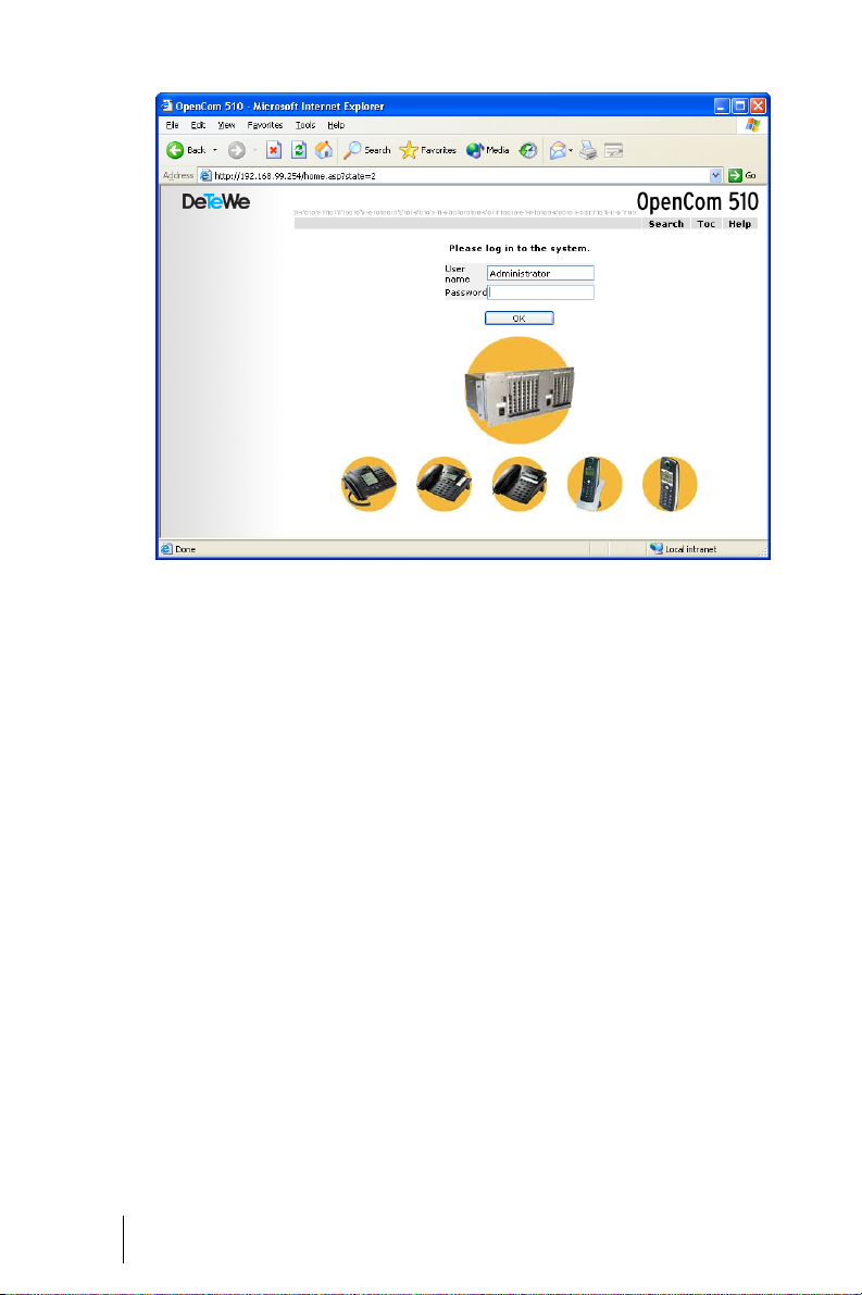
OpenCom 510: log-on dialogue box
3. To commence configuration, you
must first log on. For the initial
configuration, enter your:
- user name: “Administrator”
- password: for the initial configuration, leave this box blank.
4. Confirm this by clicking on OK.
This puts all connected terminals into the “Guest” user group
with restricted user rights. In
this way you prevent international external calls from the terminals, for example, while you
are configuring the
100OpenCom 510 and the users.
80
Configuring the OpenCom 510 Configuration
Page 83
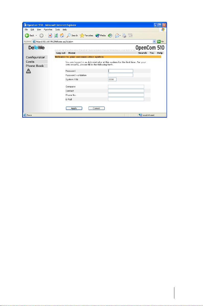
OpenCom 510: dialogue box for initial access
5. The software opens a dialogue
for initial access. Determine an
administrator password and enter it in this dialogue.
6. Confirm your input with Apply.
7. Click on the Configurator but-
ton on the home page.
You will find notes on using the Con-
figurator and in the online help.
Click on Help in the menu bar or
click on TOC to activate an overview
of help topics.
Loading the Online Help
The online help can now be loaded
in the Configurator:
1. Go to the SYS Configuration:
Components menu. Select the
entry Online Help and click on
Browse.
2. Look for one of the languagespecific ZIP files in the OLH directory of the set-up CD. Confirm
your choice by clicking on Open.
3. Then click on Load to transfer
the online help to the system.
Configuration Configuring the OpenCom 510
81
Page 84

Please note: After completion of
the loading operation, the system will
take a few minutes to analyse the
transferred file.
Note: You can downed the latest
version of the online help from
http://www.detewe.de/.
Finishing the Configuration
1. When you have completed all
the settings in the Configurator,
you must save the configuration
(see also Saving and Loading the
Configuration on page 84).
2. Then select the Log-off command in the upper menu bar.
Preconfiguration
Configuration of the OpenCom 510
can be prepared at your DeTeWe
Customer Service Centre or by an authorised DeTeWe dealer. For this purpose, a OpenCom 510 installed here
is programmed with the customer
data (e.g. user data, call distribution
schemes, cord-bound terminals).
This data is stored and then loaded
into the OpenCom 510 at the customer’s site by a service technician.
This prepared configuration must be
completed at the customer’s site
(LAN configuration and DECT terminals).
For configuration of the
OpenCom 510 Internet functions,
first ask the responsible system administrator for details of the customer’s LAN prerequisites.
Remote Configuration
The OpenCom 510 configuration can
also be altered or updated remotely
by a customer service centre or authorised dealer. This requires activation of internal RAS access in the
OpenCom 510 for the customer service centre/authorised dealer.
Note: If one or more MSNs are entered on the PBX Configuration: Sys-
tem: Remote service menu page in
the Configurator and the Status option is activated, remote configuration access is then activated when a
data call from one of the entered
MSNs is registered.
The customer service centre/authorised dealer can then log into the
OpenCom 510 as an administrator:
■ User name: “Administrator”
■ Password: administrator pass-
word
Note: If you do not wish to let the
customer service centre/authorised
dealer know the administrator password, you can define a temporary
password for remote configuration
with at least five digits.
82
Configuring the OpenCom 510 Configuration
Page 85

Use the following code digit procedure on a standard terminal or a system telephone to activate internal
remote maintenance access for the
service centre/authorised dealer:
Remote configuration on (log-on
with administrator password)
H * 1 9 *
Z (system PIN) #
Remote configuration on (log-on
with temporary password)
H * 1 9 * Z (system PIN)
* Z (temporary password) #
Remote configuration off
H # 1 9 #
Activation is automatically cancelled 30 minutes after the last configuration activity.
Note: During remote configuration, the OpenCom 510 is blocked for
RAS access by any further users.
Please note: The system PIN is
preset to “0000” and it is absolutely
imperative that the system administrator changes it to prevent undesirable remote maintenance.
Using remote configuration, all
OpenCom 510 settings with the exception of the system PIN can be edited or updated. New software versions of the OpenCom510 and the
software for the connected system
terminals and base stations can also
be installed (see the SYS Configura-
tion: Firmware menu in the Configurator).
For security reasons, settings in the
Configurator, Net Configuration
should only be edited on site to
avoid malfunctions or failures in the
customer’s LAN (e.g. due to IP address conflicts). Refer to the chapter
entitled Configuration Examples
starting on page 86, where interaction between the OpenCom 510 and
a LAN is explained.
Codes for IP Configuration
The IP configuration of the
OpenCom 510 is performed on the
Web console in the Configurator, in
the NET Configuration: Easy Access
menu.
In the event that the IP configuration of the OpenCom 510 has to be
changed and access via the Web
console is not possible, you can also
use a code digit procedure to change
these basic settings. Entry can be
made from an analogue telephone,
an ISDN telephone and from system
telephones.
Ask your system administrator for
the OpenCom 510 system PIN. The
factory setting is “0000”.
Configuration Configuring the OpenCom 510
83
Page 86

Set IP address
Loading SW Updates
H *182 Z (system PIN)
* Z (www) * Z (xxx) *
Z (yyy) * Z (zzz) #
Set NET mask
H *183 Z (system PIN)
* Z (www) * Z (xxx) *
Z (yyy) * Z (zzz) #
Restart
H * 1 8 5
Z (system PIN) #
Saving and Loading the Configuration
Configurations are saved in a file archive and can be loaded to the
OpenCom 510 either locally from a
connected configuration PC, or by
remote configuration.
The following configuration and customer data can be saved and loaded
again:
New versions of the system and terminal software can be loaded to the
system.
New software versions of the
OpenCom 510 are loaded from the
configuration PC, which accesses the
Configurator (see the SYS Configuration: Firmware menu). For infor-
mation on connecting a configuration PC, see Brief Guide to Initial
Confi guration on page 71.
The terminal software is part of the
OpenCom 510 software and is automatically loaded into the terminals
via the OpenCom 510 if the software
version in the terminal is different
from the terminal software stored in
the OpenCom 510.
Note: If you are operating an PBX
cascade, new system software is automatically transferred to the slave
system from the master system.
84
■ Telephony and network parame-
ters
For further information, refer to the
online help documentation under
the item SYS Configuration:
■ User data
■ Telephone book entries
Firmware.
Resetting the System
■ LCR tables
For further information, refer to the
online help documentation under
the topic SYS Configuration: Data
backup.
Configuring the OpenCom 510 Configuration
Data
You can restore the factory settings
of the OpenCom 510 in the Configurator.
Page 87

Please note: If this is done, all individual settings and the user data
are then lost. For this reason, you
should back up your configuration
regularly, the best time being after
every change. For details, refer to the
chapter entitled Saving and Loading
the Configuration starting on page 84
and to the Web console online help.
Proceed as follows:
1. In the Configurator, call up the
SYS Configuration: Restart
menu.
2. Click on Restart with Defaults.
3. Confirm this by pressing “OK”
when the query dialogue box
opens.
own MoH file. This program is usually located in the Windows directory called “Multimedia”.
The MoH file must be coded with
8000 Hz, 8 bit mono in accordance
with CCITT, A-Law. This coding is required for the OpenCom 510 and can
be set in the “Sound Recorder” when
you save the file under Format
(CCITT, A-Law) and Attributes (8000
Hz, 8 bit mono).
Note: If you don't have the Sound
Recorder program or the appropriate
codec on your Windows operating
system, you should install these components from your Windows CD.
Load your MoH file in the Web console's Configurator, in the SYS Con-
figuration: Components menu.
Generating Your Own MoH Files
The OpenCom 510 comes with an internal MoH file for Music on Hold.
The OpenCom 510 product CD contains a number of MoH files with different volume levels, which you can
load at a later time as necessary.
The file format for non-resident Music on Hold is *.wav. You can also
save your own MoH in a *.wav file
and load it into the OpenCom 510.
If you have a Windows operating
system, you can use the “Sound Recorder” program to generate your
Configuration Configuring the OpenCom 510
Note: When generating your own
MoH file, you may incur a fee for the
use of non-resident melodies (e.g. a
GEMA fee in Germany or MCPS fee in
the UK). The MoH files that come with
your OpenCom 510 can be used free
of charge.
85
Page 88

Configuration Examples
OpenCom 510 in Computer Networks
One of the outstanding features of
the OpenCom 510 is the integration
of telephony and computer net-
company telephone book (if the
multi-company variant is acti-
vated).
works. Connect the OpenCom 510
via a computer network (LAN) with
suitably configured workstations,
and you can use its network features
from these workstations. Using a
Web browser you can access:
In addition, the OpenCom 510 can
be used as an Internet access server.
RAS access can also be implemented
using the OpenCom 510, which enables the integration of external staff
in the LAN.
■ the OpenCom 510 Configurator
In this chapter you will find several
■ call charge administration
examples of configurations showing
integration of the OpenCom 510 in a
■ the OpenCTI 50, with which tele-
phone functions can be used on
a PC
LAN. Which example applies to your
situation depends on the size and
properties of the existing or planned
LAN infrastructure.
■ the OpenCom 510 central tele-
phone book and your personal
telephone book as well as to the
Server configuration in the LAN OpenCom 510 Functions
No IP server present OpenCom 510 functions automatically as DHCP and
DNS server
IP server present
DHCP server present
OpenCom 510 functions automatically as DHCP
client
System Administrator must assign IP address and
DNS name for OpenCom510
The following LAN prerequisites are
possible:
86
IP server present
No DHCP server present
Special case when integrating the OpenCom 510 in
a LAN; settings in the
Access” menu
sponsible system administrator
“NET Configuration: Easy
must be coordinated with the re-
OpenCom 510 in Computer Networks Configuration Examples
Page 89

Introduction to TCP/IP
In a single LAN it is possible to use
various protocols for the transmission of data. The connection between a workstation computer and
the OpenCom 510 runs via the TCP/
IP protocol used on the Internet.
TCP/IP can be used together with
other protocols (e.g. NetBEUI, AppleTalk or IPX/SPX) on the same network.
Every device participating in data
transmission using TCP/IP requires a
unique IP address. An IP address
consists of four groups of digits from
0 to 255, each separated by a full
stop. The supplementary protocols
DHCP and PPP automatically assign
IP addresses to devices. Class C networks normally use IP addresses in
which the first three numbers are
the same and the last number is
uniquely assigned to a specific device in the LAN. On the Internet,
unique addresses assigned by a special organisation created for this purpose are used. Within a LAN, you can
use addresses which are not unique
world-wide.
network mask, the connection is established via the default gateway. If
a device knows several data routes
to different intermediate stations,
one speaks of a router.
The domain name system (DNS) resolves a plain text DNS name into an
IP address. The DNS is a hierarchically structured database, distributed worldwide. A DNS server can
supply information on the names
and IP addresses for which it is responsible. For all other information,
a DNS server contacts other DNS
servers. For the establishment of
every connection from the workstation, it is possible to give either an IP
address, or a name that a DNS server
resolves into an IP address.
Note: For further explanations of
technical terms, refer to the Glossary
on the CD-ROM supplied.
TCP/IP enables the establishment of
connections via one or more intermediate stations. The decision
whether to connect directly or indirectly to the partner device depends
on the network mask. The network
mask for a class C network is
255.255.255.0. If the IP address of
the partner device does not fit the
Configuration Examples Introduction to TCP/IP
87
Page 90

OpenCom 510 in a Serverless LAN
In a peer-to-peer network, the workstations are connected to one an-
ISP
(DNS)
OpenCom
(DHCP, RAS,
int. DNS, Internet)
other via network cables. In many
networks, the cables run in the form
S
0
S0Net
of a star from a central hub. Such
networks do not require special
servers. This configuration example
is also valid for a LAN with a server
Ext.
PC
PC 1
using a protocol other than TCP/IP
(e.g. AppleTalk or IPX/SPX).
S
0
Net Hub
The OpenCom 510 in a serverless LAN
In a serverless LAN, the
OpenCom 510 takes over the IP configuration of the connected workstations. All TCP/IP settings necessary
for the workstations are assigned by
the OpenCom 510 via DHCP (dynamic host configuration protocol).
In this operating mode, an IP address space reserved for such networks is used:
192.168.99.254 OpenCom 510 IP address
PC 2
Net
88
192.168.99.129 to 192.168.99.148 DHCP addresses: IP address space for workstations
192.168.100.0 to 192.168.100.10 PPP addresses: IP address space for RAS
dialling
255.255.255.0 Network mask (class C network)
192.168.99.254 DNS server IP address
192.168.99.254 Default gateway IP address
OpenCom 510 in a Serverless LAN Configuration Examples
Page 91

Install the TCP/IP network protocol
and a Web browser for every workstation which is to have access to the
OpenCom 510 network features.
For notes on installing network
cards, refer to Connection by Network
Card (LAN) on page 75.
DNS Name Resolution
In a serverless LAN, the internal DNS
name resolution is performed by the
OpenCom 510. If you type the string
“host.domain” into your browser, a
DNS request is sent to the
OpenCom 510 IP address. The
OpenCom 510 responds with the
correct IP address, so that the Con-
figurator home page can be called
up.
In a peer-to-peer network (Windows
network), the workstations each
have a name which is displayed in
the network environment. These
NetBIOS names can differ from the
DNS names assigned to the workstations by the OpenCom 510. The
OpenCom 510 is not visible in the
network environment.
Internet Access
If access to an ISP has been configured on the OpenCom 510, the
OpenCom 510 can be operated as an
Internet access server without any
additional configuration of the
workstations. When you want to see
a Web page, you simply type the URL
(uniform resource locator; Internet
address; “http://...”) in your browser.
In a serverless LAN, the
OpenCom 510 is configured as a DNS
server and default gateway. The
workstation therefore sends its Internet connection request to the
OpenCom 510.
In almost all cases, the request will
contain a DNS name which is unknown in the internal network.
When you type a URL into your
browser, the OpenCom 510 receives
the request to find the corresponding IP address. If the name is unknown in the LAN, the request is forwarded to an ISP’s external DNS
server.
Note: Workstation PCs automatically add a domain name to URLs
without a dot. You specify this domain name in the Configurator. For
example, if you have configured
“firm.co.uk” as the domain name, an
access request for “www.firm.co.uk”
will be interpreted as a local DNS request which does not lead to the establishment of an Internet connection. For this reason, you should
choose a name which is not used in
the Internet as the domain name
(“firm-opencom.co.uk” for example).
Configuration Examples OpenCom 510 in a Serverless LAN
89
Page 92

RAS Access
You can establish a connection from
an external computer with an ISDN
card to the OpenCom 510. The necessary TCP/IP settings are transmitted by the OpenCom 510 on establishment of the connection. The
computer that has dialled in now
has access to all services in the LAN
capable of being used via TCP/IP. The
authorisation for RAS access is set up
in the Configurator via the User
Manager: User Groups menu.
In a serverless LAN, Windows uses
the NetBIOS protocol for accessing
files and printers via the network environment. NetBIOS can use NetBEUI, IPX/SPX or TCP/IP as the transport protocol. In the network
environment, you can only access
files and printers on workstations using TCP/IP for NetBIOS.
90
Note: In a serverless LAN, the work-
stations running decide independently which one is to keep the list of
names visible in the network environment. This process is triggered by
broadcasts, which can take some time
on a RAS connection. You can shorten
this period by activating the “Find >
Computer” function in the Start menu
and selecting the client computer.
OpenCom 510 in a Serverless LAN Configuration Examples
Page 93
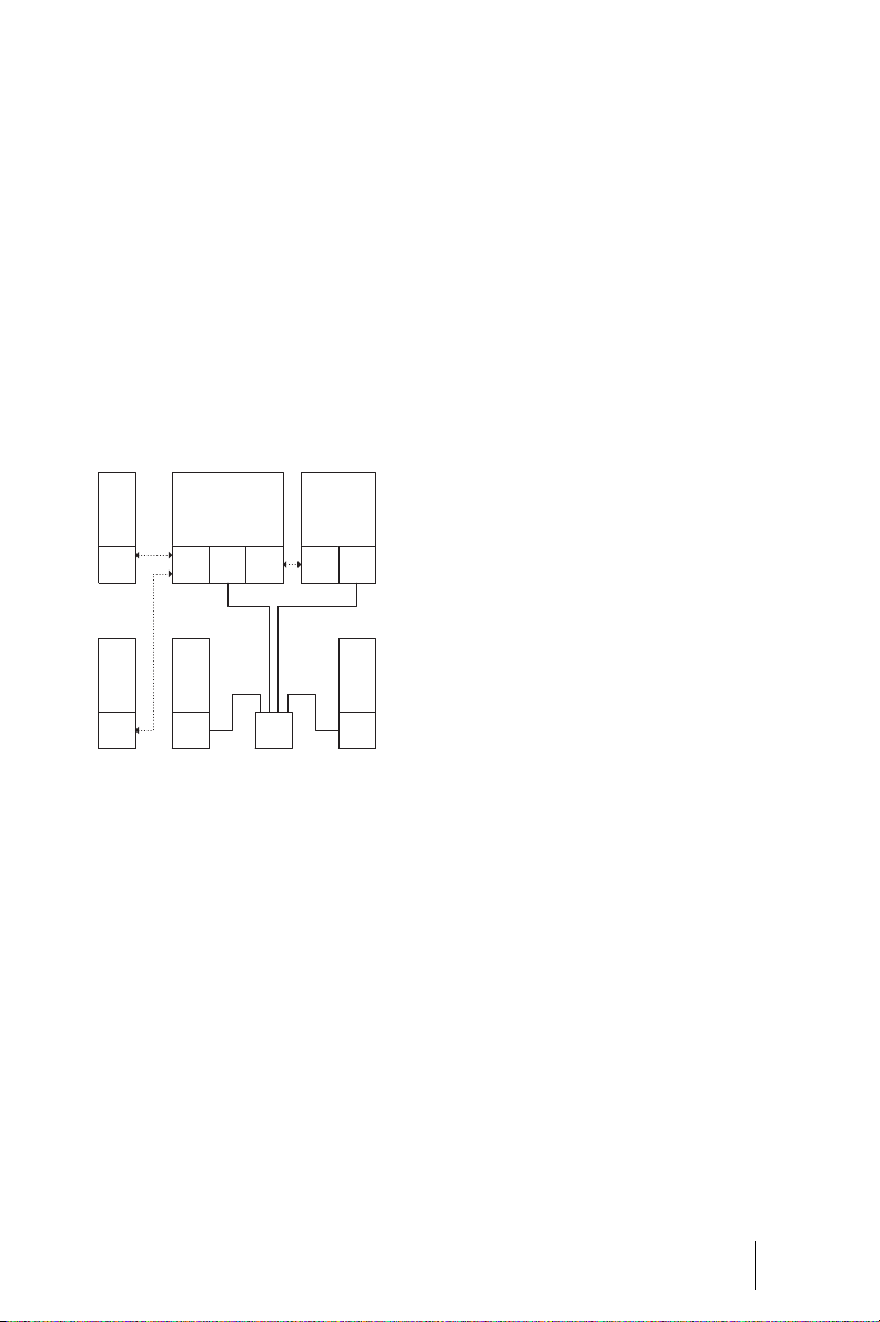
OpenCom 510 in a LAN with an IP-enabled Server
In a LAN with an IP-enabled server,
you should coordinate integration of
the OpenCom 510 with the responsible network administrator. You must
decide on the IP address space to be
used and which network services
(DHCP, DNS, RAS, Internet access)
the OpenCom 510 is to handle in the
LAN.
ISP
(DNS)
S
Ext.
PC
S
0
0
OpenCom
S0Net
S0 int
PC 1
Net Hub
Server
(DHCP, RAS,
int. DNS,
Internet)
S0Net
PC 2
Net
The OpenCom 510 in a LAN with an
IP-enabled server
In many cases, an IP-enabled server
configures the TCP/IP settings via
DHCP for all workstations. On starting, the OpenCom 510 requests TCP/
IP settings via DHCP. If this request is
responded to, the OpenCom 510
uses the TCP/IP settings received.
You can then use a workstation to
access the OpenCom 510 Configura-
tor under the IP address assigned by
the server.
In networks in which the TCP/IP settings are made manually, you have
to enter the corresponding TCP/IP
settings in the OpenCom 510 Con-
figurator (NET Configuration: Easy
Access menu). Here the
OpenCom 510 acts as the DHCP
server. A workstation requesting the
TCP/IP settings via DHCP then receives the settings you made in the
Configurator.
DNS Name Resolution
In a LAN with an IP-enabled server,
the latter is also responsible for DNS
name resolution. If you want to start
the Configurator by entering a DNS
name, you must link this name on
the server with the IP address used
by the OpenCom 510. For further information, refer to the server documentation.
Note: To access the OpenCom 510
under the same IP address after a restart, you must specify this IP address
permanently on a DHCP server. On a
DHCP server it is possible to link the
MAC address of a network card with a
specific IP address. You will find details in the server documentation.
Configuration Examples OpenCom 510 in a LAN with an IP-enabled Server
91
Page 94

Internet Access
You can also use the OpenCom 510
as an Internet access server in a LAN
with an IP -enab led server. To d o this,
you must enter the OpenCom 510 IP
address on the server as the default
gateway. In addition, you must edit
the internal DNS server configuration so that the resolution of external DNS names is forwarded to the
OpenCom 510.
In this example, the Internet connection is established from a workstation via the server, which in turn requests Internet access from the
OpenCom 510.
There are two different ways of suitably configuring the internal DNS
server. You can enter the
OpenCom 510 IP address as a DNS
forwarder. If you require access to
extended DNS information, you can
also configure the DNS server for a
recursive DNS request without the
DNS forwarder. For further explanation, refer to the DNS server documentation.
ISP
(DNS)
S
Ext.
PC
S
OpenCom
(Internet)
S0Net
0
PC 1
0
Net Hub
S0 int
Server
(DHCP, RAS,
int. DNS)
S0Net
PC 2
Net
The OpenCom 510 as a DNS server in a
LAN with an IP server
RAS Access
In a LAN with an IP-enabled server
you can also enable external computers to dial in via the
OpenCom 510. To do this, you should
coordinate with the network administrator the IP address space which
can be assigned to an external computer dialling in, and enter it in the
Configurator, NET Configuration:
Easy Access menu, under PPP Addresses.
The user account administered by
the OpenCom 510, with which dialling in is permitted, only allows the
establishment of direct and anonymous TCP/IP connections such as
HTTP, FTP or SMTP connections. If
you additionally want to allow file or
printer access in the network, you
must set up a suitable user account
on the addressed server for network
log-in. If you use the same log-in
name for the OpenCom 510 user ac-
92
OpenCom 510 in a LAN with an IP-enabled Server Configuration Examples
Page 95

count and the same password for
the network log-in, you have to enter this combination only once when
dialling in.
ISP
(DNS)
S
Ext.
PC
S
0
0
OpenCom
(RAS, Internet)
S0Net
PC 1
Net Hub
Server
(DHCP,
int. DNS)
Net
PC 2
Net
RAS access by the OpenCom 510 in a
LAN with an IP server
Note: In a larger Windows network
with several segments, the lists of
computer names visible in the network environment can no longer be
established by broadcasts. In this case
you use a special WINS server whose
address the OpenCom 510 does not
make known to the workstation
when dialling in. For this reason, you
enter the address of a WINS server
manually in the network settings of
the workstation.
Configuration Examples OpenCom 510 in a LAN with an IP-enabled Server
93
Page 96
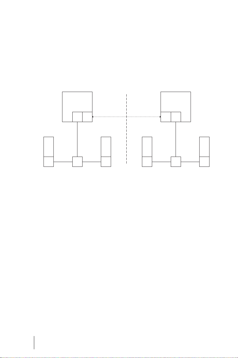
LAN-to-LAN Link
You can use the OpenCom 510 to interlink two LANs via ISDN. To do this,
you configure two OpenCom 510
systems so that they can dial in to
each other. In order for this to work,
the two LANs must be configured for
OpenCom
(IP=192.168.99.254,
Net=192.168.99.0)
S
Net
0
PC 1
Net Hub
PC 2
Net
The OpenCom 510 in a LAN-to-LAN link
In the Configurator, NET Configura-
tion: LAN-LAN menu you can con-
figure the dial-in settings. The
OpenCom 510 will set up a connection whenever a TCP/IP data transfer
to the other LAN is requested.
different IP address ranges (subnetworks). For at least one of the
OpenCom 510 systems, change the
prescribed address range for the
LAN.
OpenCom
(IP=192.168.11.254,
Net=192.168.11.0)
S0Net
PC 1
Net Hub
PC 2
Net
As the IP address range, you can select one of the 256 class C subnetworks designed for local LANs.
Select a class C sub-network in the
range from 192.168.0.0 to
192.168.255.0.
94
Note that such a connection is only
set up when specific requests are
made. These can be for FTP file
transfers, e-mails or downloading
Web pages. Name resolution via
broadcasts is not possible. If you
wish to use the LAN-to-LAN link to
access files and printers in the Windows network, you need an IP-enabled server that administers the
name resolution for the Windows
network.
LAN-to-LAN Link Configuration Examples
Page 97

Useful Information on Internet Access
Costs
The OpenCom 510 uses a router
function to access the Internet,
which means that it automatically
establishes an Internet connection
when required and terminates the
connection after a certain period of
time if no data are being transmitted.
Unfortunately, programs other than
those typically intended to access
the Internet (such as your browser or
your e-mail software) may send out
data packets which cause an Internet connection to be established,
even if these programs are not
strictly Internet-associated applications.
Examples of such programs are the
Microsoft
various multimedia programs such
as Realplayer
cations that may establish an Internet connection for automatic updates (the so-called “phone home
function”).
It is therefore highly advisable to
limit ISP access by specifying the
maximum monthly connection time
under Connection time per month
(maximal) in the NET Configuration: Connections: ISP menu on the
web console.
TM
XPTM operating system,
TM
and anti-virus appli-
Using the Web
A Web browser not only enables you
to use the OpenCom 510 Configura-
tor from every workstation but also
to obtain a wealth of information
from the Internet. Simply enter the
desired URL in the address field of
the browser. Access from a standalone PC via an online service differs
from Internet access via the
OpenCom 510 in the following respects:
■ When you request a Web page,
dialling in results automatically.
There is no display of dialogues
with manual confirmation of dialling in or hanging up.
■ Requesting Web pages is not a
connection-orientated service.
When the Web page has been
loaded completely, the TCP/IP
connection is cleared. If you do
not request further Web pages,
the OpenCom 510 automatically
releases the connection to the
Internet after a certain, specifiable duration.
■ It is possible to call up Web
pages simultaneously from several workstations.
■ The OpenCom 510 can block ac-
cess to certain Web pages by
means of filter lists.
Configuration Examples Useful Information on Internet Access
95
Page 98

E-mai l
One of the most important services
in the Internet is e-mail. E-mails are
buffered in individual e-mail accounts on a mail server. Mail servers
are operated by ISPs for example.
With the OpenCom 510 you can set
up one or more e-mail accounts for
every user account configured on
the OpenCom 510. These e-mail accounts are then checked at regular
intervals.
If there are new e-mails in an e-mail
account, and the OpenCom 510 has
been configured for this function,
the user specified in the
OpenCom 510 user account is notified of the new e-mail on his system
terminal. System telephones from
the OpenPhone 6x and 2x product
range can also display information
such as the sender or the subject of
the e-mail.
NAT
single account with the Internet
service provider.
■ The IP addresses used in the LAN
are translated into IP addresses
valid worldwide. So you require
no such addresses for your LAN.
■ Only TCP/IP connections trig-
gered from a workstation can be
established. Consequently, while
you can call up Web pages from
a workstation, you cannot install
a Web server visible in the Internet on a workstation.
Certain protocols cannot be used
when NAT is being used. This affects
protocols with the following properties:
■ TCP/IP addresses are trans-
ported in the useful load, e.g.
NetBIOS over TCP/IP.
■ The protocol requires an active,
inward-directed connection establishment, e.g. ICQ.
96
Network address translation (NAT) is
activated on accessing the Internet
(ISP). You require this feature in or-
■ The protocol will function with-
out TCP/UDP port numbers, e.g.
ICMP or IGMP.
der to translate internal IP addresses
to valid external IP addresses. This
has three important consequences
for Internet access:
The OpenCom 510 NAT has suitable
processes for ensuring the functions
of many important protocols affected by these rules. These are the
■ Several workstations can share a
single Internet access. You do
not require a LAN access, only a
protocols FTP (in “active” mode), CuSeeMe (“videoconferencing”), IRC
(“chat”), ICMP errors (“traceroute”)
and ICMP echo (“ping”).
Useful Information on Internet Access Configuration Examples
Page 99

Protocols which require inward-directed connection establishment
can be configured in the Net Config-
uration: Port Access menu. For further information, refer to the online
help of this menu.
Configuration Examples Useful Information on Internet Access
97
Page 100

PBX Networking
As requirements grow, the
OpenCom 510 can be operated together with other PBX installations.
If you merely need a larger number
of connections, it is easy to link a
second PBX (“PBX Cascading”). If you
want to operate the OpenCom 510
at several locations with different
PBXs, this is possible by PBX Net-
working.
PBX Cascading
You can combine two PBXs in order
to increase the number of terminals
that can be connected. A master PBX
and a slave PBX are connected to
one another by means of a cable.
The two PBXs essentially function
Master PBX Slave PBX
OpenCom 120 OpenCom 105, OpenCom 110,
OpenCom 130 OpenCom 105, OpenCom 110,
OpenCom 150 OpenCom 150
OpenCom 510 OpenCom 510
like a single PBX with a higher
number of ports. The master PBX
controls the slave PBX. The following
PBXs from the product family can be
used for cascading:
OpenCom 120
OpenCom 120 or OpenCom 130
98
Note: The OpenCom 107 is not
equipped with a PCM port. For this
reason, PBX cascading is not possible
with this PBX.
For the PBX Cascading you will need
a license. The license agreement provides you with the necessary steps
to activate this function
PBX Cascading PBX Networking
Functionality of PBX Cascading
Cascaded PBXs must be connected
by means of a twisted-pair lead with
RJ45 plugs. All eight pins of the lead
must be wired 1 to 1. Both voice and
administration data are transferred
via this lead. Connect the lead to the
PCM ports of the two MC+1-3 cen-
 Loading...