

Page 1
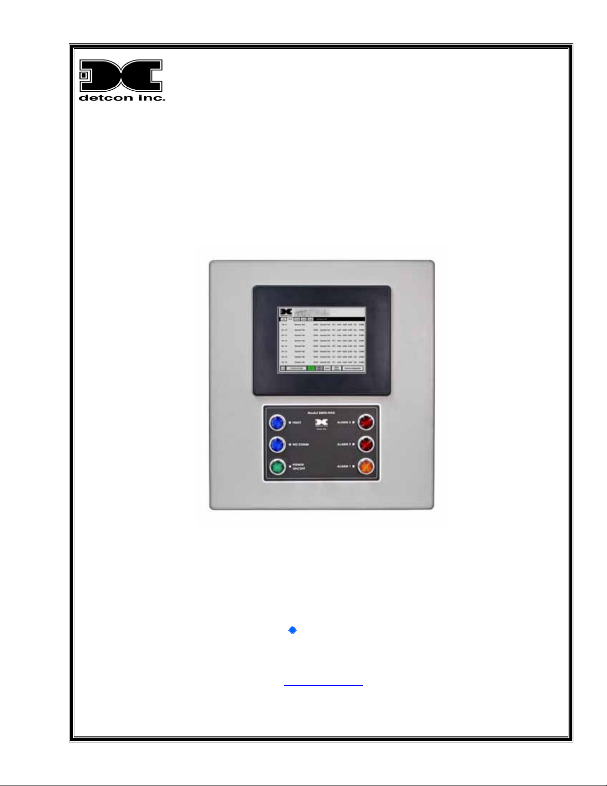
Model 880A-N4X
Model 880S-N4X
PLC Graphic Control System
Operator’s Installation and Instruction Manual
3200 Research Forest Dr., A-1
The Woodlands, Texas 77381
Ph.281.367.4100 / Fax 281.298.2868
DETCON, Inc.
www.detcon.com
February 25, 2009 • Document # 3290 • Revision 0.0
Page 2

880-N4X
Page intentionally blank
880-N4X Instruction Manual ii
Page 3

880-N4X
Table of Contents
Introduction.............................................................................................................................................1
1.0
1.1 Analog Systems (4-20mA sensors) ...................................................................................................... 1
1.2 Serial Systems (RS-485) ...................................................................................................................... 1
2.0 System Configuration .............................................................................................................................3
2.1 Configuration........................................................................................................................................ 3
2.2 Touch Panel Graphic Display............................................................................................................... 3
2.3 Programmable Logic Controller........................................................................................................... 4
2.4 Isolated Network Adapter .................................................................................................................... 4
2.5 Specifications ....................................................................................................................................... 5
3.0 Installation...............................................................................................................................................7
3.1 Initial Power Checks .......................................................................................................................... 10
3.2 Auxiliary 24VDC Input...................................................................................................................... 10
3.3 880 Remote Display Installation (Optional)....................................................................................... 10
4.0 Setup.......................................................................................................................................................13
4.1 User interface ..................................................................................................................................... 13
4.2 Clock and Screen Adjustments........................................................................................................... 14
4.3 880 Setup............................................................................................................................................ 16
4.4 Remote Display Set-up....................................................................................................................... 20
5.0 System Operation..................................................................................................................................22
5.1 Alarm Indicators................................................................................................................................. 22
5.2 Main Screen........................................................................................................................................ 22
5.3 Channel X Details Screen................................................................................................................... 23
5.4 Alarm History Screen......................................................................................................................... 24
6.0 Trouble-shooting ...................................................................................................................................25
6.1 Sensor Faults ...................................................................................................................................... 25
6.2 Troubleshooting RS485 Networks..................................................................................................... 25
7.0 Spare Parts.............................................................................................................................................27
8.0 Warranty................................................................................................................................................27
Appendix A........................................................................................................................................................28
RS-485 System Integration Wiring................................................................................................................ 28
Appendix B ........................................................................................................................................................34
Hexadecimal Table......................................................................................................................................... 34
Appendix C........................................................................................................................................................35
Drawings and Diagrams................................................................................................................................. 35
Table of Figures
Figure 1 DA4 4-20mA Configuration.................................................................................................................. 1
Figure 2 RS-485 Network Configuration............................................................................................................. 2
Figure 3 Back of Touch Panel Display................................................................................................................. 3
Figure 4 Basic PLC .............................................................................................................................................. 4
880-N4X Instruction Manual iii
Page 4

880-N4X
Figure 5 FA-ISOCON Module............................................................................................................................. 5
Figure 6 Unit overview......................................................................................................................................... 5
Figure 7 Dimensional Overview .......................................................................................................................... 7
Figure 8 Typical RS-485 connections.................................................................................................................. 8
Figure 9 Typical Analog Sensor Wiring .............................................................................................................. 8
Figure 10 Alarm Relay Connections.................................................................................................................... 9
Figure 11 Typical 24VDC Input Connections...................................................................................................... 9
Figure 12 Typical Input Power connections......................................................................................................... 9
Figure 13 24VDC adjustment............................................................................................................................. 10
Figure 14 Dimensional Overview ...................................................................................................................... 11
Figure 15 Main 880 terminal blocks and connections........................................................................................ 11
Figure 16 Remote RS-422 connections.............................................................................................................. 12
Figure 17 Remote Interconnect Wiring.............................................................................................................. 12
Figure 18 Typical Input Power connections....................................................................................................... 12
Figure 19 Input Keyboard .................................................................................................................................. 13
Figure 20 Input Keypad...................................................................................................................................... 13
Figure 21 Warning Screen.................................................................................................................................. 14
Figure 22 Main Menu......................................................................................................................................... 14
Figure 23 Screen Settings................................................................................................................................... 15
Figure 24 Clock Adjust Screen........................................................................................................................... 15
Figure 25 Adjust Display Screen........................................................................................................................ 15
Figure 26 Main Screen....................................................................................................................................... 16
Figure 27 Analog Configuration Screen............................................................................................................. 16
Figure 28 Serial Configuration Screen............................................................................................................... 17
Figure 29 Inputting the Facility Name ............................................................................................................... 17
Figure 30 Inputting the number of channels....................................................................................................... 18
Figure 31 Channel Detail Screen........................................................................................................................ 18
Figure 32 The Main Screen................................................................................................................................23
Figure 33 Channel Details Screen...................................................................................................................... 24
Figure 34 Alarm History Screen......................................................................................................................... 24
Figure 35 RS-485 Bus with 4 transceiver chips................................................................................................. 28
Figure 36 Correct and incorrect wiring schemes................................................................................................ 29
Figure 37 Recommended RS-485 communications set-up ................................................................................ 30
Figure 38 Unbalanced Data Bus......................................................................................................................... 31
Figure 39 Data Bus using two repeaters............................................................................................................. 31
Figure 40 Repeater wiring diagram.................................................................................................................... 31
Figure 41 Daisy Chain wiring diagram.............................................................................................................. 32
Figure 42 Unbalanced Data Bus......................................................................................................................... 32
Figure 43 Four repeater Data Bus ...................................................................................................................... 33
Figure 44 wire length vs. data speed.................................................................................................................. 33
Shipping Address: 3200 A-1 Research Forest Dr., The Woodlands Texas 77381
Mailing Address: P.O. Box 8067, The Woodlands Texas 77387-8067
Phone: 888.367.4286, 281.367.4100 • Fax: 281.292.286 0 •
880-N4X Instruction Manual iv
www.detcon.com • [email protected]
Page 5
880-N4X
1.0 Introduction
The standard Detcon Model 880 is a PLC based graphic control system specifically designed to serve as a host
monitoring and control system for networks of gas detection sensors as well as a wide range of other field
devices. The main unit is programmed as a Modbus master and is available in two versions: Serial (Model
880S-N4X) and Analog (Model 880A-N4X). Both are fully Field configurable and include a NEMA 4X rated
control enclosure, which is rain tight and suitable for outdoor locations in electrically non-hazardous
environments.
The Serial unit (Model 880S-N4X) is designed to monitor up to 32 serial field devices, while the Analog
version (880A-N4X) can monitor up to 72 analog devices via Detcon’s DA4 Modules. The unit features a
color touch screen that graphically displays the status of each device, provides three fully programmable
“Banks” of alarm outputs, and logs alarm events to a USB Drive. The use of standard industrial components
makes Detcon Model 880 an easy and practical choice when configuring point-to-point monitoring and data
acquisition. The system can also be used for remote monitoring simply by adding the 880 Remote Display
Unit.
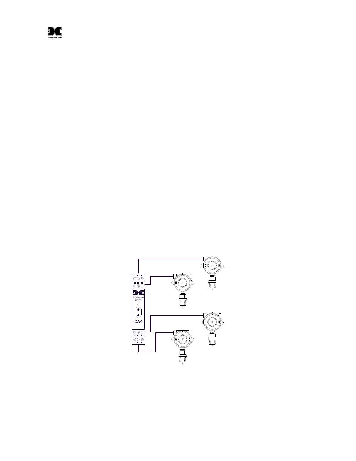
1.1 Analog Systems (4-20mA sensors)
The signal outputs from multiple sensors provide the user with various options for integrating the Model 880
Graphic Control System. One method of integration is accomplished by using 4-20mA signal output gas
sensors with Detcon DA4 Modules (Figure 1). The DA4 Module receives an analog 4-20mA signal
corresponding to the range of detection then changes it to Modbus™ before relaying the information to the
880A. The Sensor’s output signal is calibrated so that a 4mA input represents a reading of “0” and a 20mA
input represents a reading of full scale. The scale used for each sensor is user programmable and can be set in
the field. Readings outside the range of 4-20mA will cause a Fault.
Sensor 4
COMM
M
S
D
L
S
D
4-20mA
INPUT
Sensor 3
Typical Sensors
Sensor 1
Sensor 2
Figure 1 DA4 4-20mA Configuration
Analog 4-20mA networks are typically recognized as the most fail-safe approach. When using DA4
Module(s), the 880A can communicate with up to 72 analog input channels.
1.2 Serial Systems (RS-485)
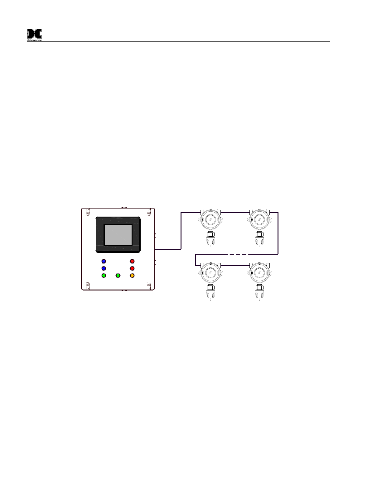
Another method of integration commonly used in industrial applications is the RS-485 serial communications
880-N4X Instruction Manual Rev. 0.0 Page 1 of 36
Page 6
880-N4X
network, or Modbus™ (Figure 2). RS-485 serial communication is used for multipoint communications and is
a popular choice due to ease of wiring installation.
Advantages of using RS-485 serial communication:
¾ Inexpensive method allowing multiple devices to communicate over a single twisted pair of wires.
¾ More data/information can be sent beyond the simple 4-20mA signal.
¾ Transceiver communication up to 4,000 feet without using repeaters.
¾ Highly resistant to induced noise when proper cable and terminations are used.
¾ Two-way (bi-directional), half-duplex, data bus communication consisting of multiple transmitter and
receiver combinations.
Most systems use the RS-485 master/slave architecture for multiple device communication. Each slave unit
has a unique address and responds to data packets generated by the master. The master periodically polls all
connected slave units.
The protocol used by Detcon for the RS-485 communications is the Modbus™ RTU, which is compatible with
most PLC’s, MMI’s, and distributed control systems. The Modbus™ RTU protocol is standard and allows for
a maximum of 32 sensors and/or field devices to be used in this configuration.
1 2
Typical Sensors
ALARM 3
FAULT
NO COMM
ALARM 2
POWER
ON / OFF
ALARM 1
31 32
Figure 2 RS-485 Network Configuration
880-N4X Instruction Manual Rev. 0.0 Page 2 of 36
Page 7
880-N4X
2.0 System Configuration
The Model 880 is designed to monitor and display the status of field sensor devices, provide programmable
alarm outputs, and log alarm incidents via a USB drive. The system is equipped with a color graphic touch
screen display. Control electronics are industry standard PLC modules pre-selected to fit the application.
Twelve 10Amp relays provide three “Banks” of four relays, each designed to give Alarm 1, Alarm 2, Alarm 3
and Fault conditions for each related bank. Each relay provides one set of contacts: Common, Normally Open,
and Normally Closed for customer annunciator connection.
2.1 Configuration
A Model 880 is equipped with:
• 8.31" x 6.24" (211.2 x 158.4 mm) Color Graphical Touch Screen display panel
• Six slot Programmable Logic Controller (PLC)
o Two communication port CPU Module
o Twelve channel Relay Output Module
o Eight channel Relay Output Module
o Communications Module (2ea.)
• Isolated Network Adapter
• 24VDC 10Amp Power Supply
• (12) 10amp 1PDT DC Alarm Relays
• Fault, Alarm, Communications, and Power Panel Indicator LED’s
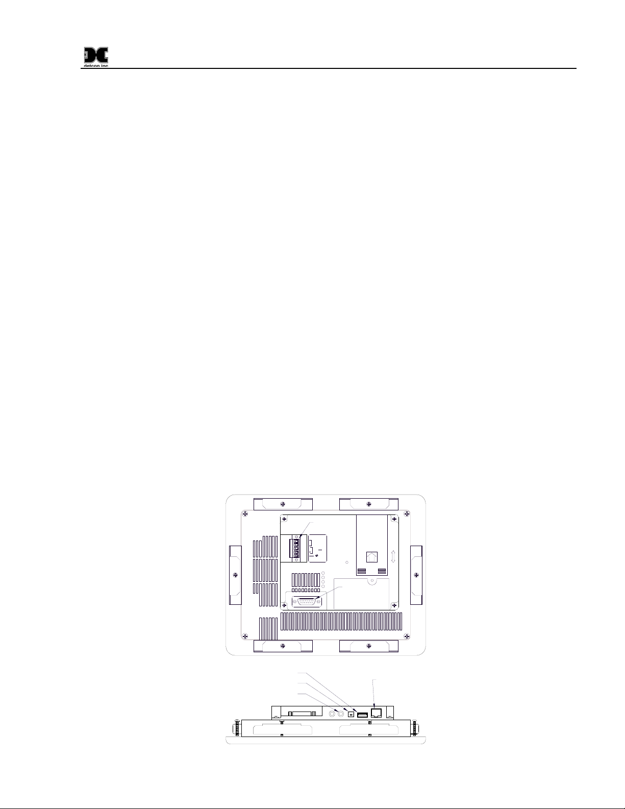
2.2 Touch Panel Graphic Display
The Model 880 is equipped with a graphic display panel (Figure 3) that is prompted to display information
such as the operational status of each monitoring device, alarm output readings, and record alarm incidents to a
USB Drive.
DC Input
NOT
Used
+
24V . . . .
Dedicated
power supply
recommended
PWR
CPU
TxD
RxD
PLC Serial Port
BACK VIEW
USB Type A Port
USB Type B Port
Audio Line Out
BOTTOM VIEW
Ethernet 10/100
Base T Connector
Figure 3 Back of Touch Panel Display
880-N4X Instruction Manual Rev. 0.0 Page 3 of 36
Page 8
880-N4X
The touch panel acts as a master interface to the internally located PLC. As such, the touch panel polls the
PLC, which, in turn, polls the field devices for information. A wand is used on the screen to operate system
controls and/or move to additional screens.
A USB port (Figure 3) is located on the back of the display at the bottom. When a USB Drive (USB Memory
Stick) is installed, the display will automatically log to the drive where any alarms and/or faults have been
recorded by the PLC. The information is logged into a folder named ‘Log’ and named ‘Alarm_yymmdd.txt’
where yy is the year, mm is the month, and dd is the day. The files are written in text format.
2.3 Programmable Logic Controller
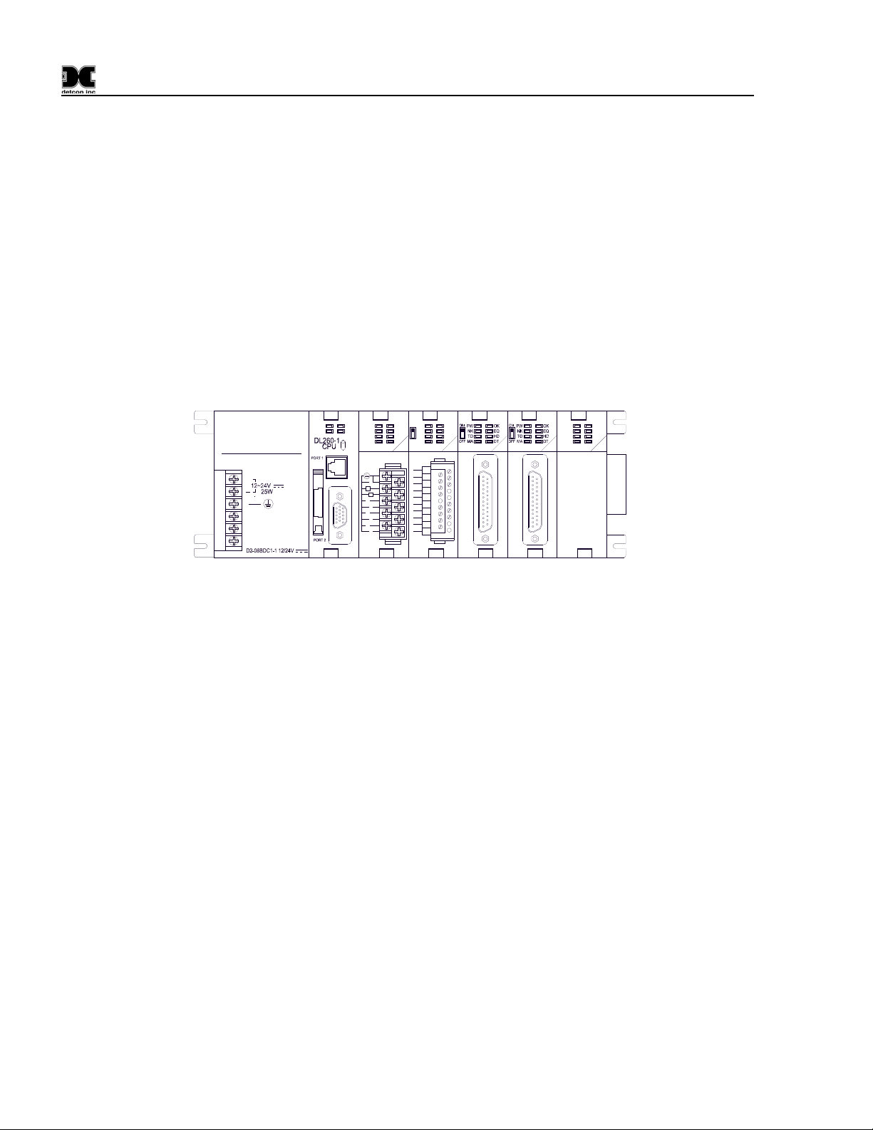
At the core of the Model 880 is the modular Programmable Logic Controller (PLC), which is designed to offer
maximum flexibility in system configuration (Figure 4). The PLC and all other electronic components are
mounted within the enclosure.
OUT RELAY
A
B
D2-12TR
5-240VAC
1.5 50/60Hz
5-30VDC
5mA-1.5A
0
1
2
3
0
1
2
3
4
0
5
1
6
2
7
3
CA
4
5
CB
4
5
4
0
5
1
6
2
7
3
C
C
0
L
4
L
1
5
2
6
3
7
D2-DCM
DATA
D2-DCM
DATA
COM
SPARE
4
0
5
1
6
2
7
3
COM
Direct
LOGIC
+
205
G
CPU
BATT
OUT RELAY
RELAY
PWR
RUN
CPU
RUN
TERM
D2-08TR
STOP
5-240VAC
1A 50/60Hz
5-30VDC
5mA-1A
Figure 4 Basic PLC
Installed in the PLC is the programmable Central Processing Unit (CPU), which processes all instructions,
data, and polls all field devices. The CPU utilizes flash memory to store the running program. All units are
shipped with firmware loaded and a lithium battery installed. The CPU has two communication ports. The
top RS232 port (Port 1) is the programming and interface for the touch display panel. The 15-pin bottom port
(Port 2) supports RS232 or RS422 and serves as I/O master for the RS-485 Modbus™ network.
The PLC contains an 8-channel and a 12-channel Relay Output Module. The 8-channel relay output module
controls the LED’s on the front panel of the unit, while the 12-channel relay output module controls the 12
10Amp relays used for customer supplied Alarm 1, Alarm 2, Alarm 3 and Fault circuits or annunciators. The
relays are labeled in ‘Banks’ as “ALARM 1”, “ALARM 2”, “ALARM 3”, and “FAULT”.
Remote Display and Auxiliary units utilize the two Data Communication Modules. The modules are used for
communication with the Remote Display, printers, and other external compatible devices.
2.4 Isolated Network Adapter
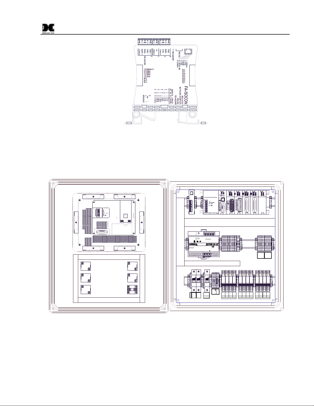
The Model 880 PLC uses an Isolated Network Adapter to interface devices on the RS-485 Modbus™ network.
The Isolated Network Adapter (Figure 5) converts RS-422/485 signals from sensors and other digital devices,
to an RS-232 signal that the main CPU can utilize.
880-N4X Instruction Manual Rev. 0.0 Page 4 of 36
Page 9
880-N4X
A
Figure 5 Isolated Network Adapter
The Isolated Network Adapter performs well in noisy environments where data corruption is possible due to
induced noise. The Isolated Network Adapter can also be used to verify whether or not the unit is
communicating and polling. To simplify troubleshooting, the Isolated Network Adapter has transmit and
receive LED’s.
OUT RELAY
G
B
A
RS-485 VDC
Primary Out
OUT RELAY
CPU
PWR
RUN
4
0
BATT
CPU
5
1
6
2
RUN
7
3
TERM
D2-08TR
STOP
5-240VAC
1A 50/60Hz
C
C
0
L
4
L
1
5
2
6
3
7
5-30VDC
5mA-1A
+
11-NC
11-NC
11-NC
14-NO
14-NO
14-NO
12-COM
12-COM
12-COM
12-COM
FLT
ALM2
ALM1
BANK 1
A
Direct
RXD
TXD
TXD EN
B
TXD
RXD
CTS
C-A
+V
C-A
TX+
TXRX-
NOT
Used
+
24V . . . .
Dedicated
power supply
recommended
PWR
CPU
TxD
RxD
X1
ALARM 3
X2
X1
ALARM 2
X2
X1
ALARM 1
X2
FAULT
NO COMM
ON / OFF
X1
X2
X1
X2
RX+
C-B
C
C
45JB
Made in China
Input DetailsInput Details
100-240VAC 3.5A Maximum
100-240VAC 3.5A Maximum
Power Factor Corrected
Power Factor Corrected
Frequency : 50/60HzFrequency : 50/60Hz
C3
WMS1C03
240V- 100 00
I ON
Ground
NEU (L2)
205
LOGIC
+
+V+V+V+V -V-V -V-V
DC ONDC ON
Output DetailsOutput Details
HH
Continuous Loading 24VDC/10AContinuous Loading 24VDC/10A
V.ADJV.ADJ
ALMALM
RR
US
US
USC
USC
LN
C3
C10
WMS1C03
WMS1C10
240V- 10 000
240V- 1 0000
I ON
I ON
24V -
24V +
24VDC
VAC (L1)
INPUT
DATA
DATA
COM
A
4
0
5
1
6
2
B
7
3
D2-12TR
5-240VAC
1.5 50/60Hz
5-30VDC
5mA-1.5A
CA
0
4
1
5
2
3
CB
0
4
1
5
2
3
11-NC
11-NC
14-NO
14-NO
12-COM
ALM3
FLT
COM
4
0
5
1
6
2
7
D2-DCM
11-NC
14-NO
12-COM
ALM1
BANK 2
3
D2-DCM
SPARE
0V
0V
TXD-
TXD-
RXD-
RXD-
TXD+
TXD+
RXD+
RXD+
REMOTE
RS-485
OUTPUT
SLAVE
11-NC
11-NC
11-NC
11-NC
11-NC
14-NO
14-NO
12-COM
12-COM
ALM2
ALM3
11-NC
14-NO
14-NO
14-NO
14-NO
12-COM
12-COM
12-COM
12-COM
FLT
ALM2
ALM3
ALM1
BANK 3
Figure 6 Unit overview
2.5 Specifications
Capacity
User Configurable
Serial Units: Up to 32 serial devices
Analog Units: Up to 72 analog inputs using the Detcon DA-4 Modules
880-N4X Instruction Manual Rev. 0.0 Page 5 of 36
Page 10

880-N4X
Inputs
RS-485 Modbus™ RTU
Outputs
User Configurable Relays:
Three Banks of 4 relays per Bank (Fault, Alarm 1, Alarm 2, and Alarm 3) – 12 relays
Relay maximum continuous operating current: 10A
Maximum inrush current 30A (300ms)
Primary: RS-485
Slave: RS-485
Remote Output: RS-422
Power Input
100-240VAC 50~60Hz
18-30VDC
Power Consumption
Base Unit <120W
Total Power is dependent on number of I/O modules, number of sensors, and the type of sensors attached.
Total power of unit with I/O modules and gas sensors not to exceed 200 Watts.
Display
8” inch diagonal Graphic Backlit LCD Touch screen display
Electrical Classification
NEMA 4 Enclosure
Dimensions
18''W x 20''H x 8.75''D
Operating Temperature Range
0°C to +45°C
Warranty
One year
880-N4X Instruction Manual Rev. 0.0 Page 6 of 36
Page 11

880-N4X
3.0 Installation
The Detcon Model 880 PLC is a wall-mount enclosure, and can be mounted anywhere that is rated safe for
NEMA 4X enclosures. The enclosure is equipped with four (4) wall-mounting brackets for easy wall mount
installations. Care should be given to prevent sharp objects from colliding with the touch screen display as
damage to the display may cause the unit to become inoperative. The screen can be cleaned with a mild
detergent and a lint free cloth. Never use an abrasive cleaner on the display.
1. Securely mount the 880 Enclosure in accordance with Figure 7.
18.0"
Ø0.3"
15.0"
8.8"
8.5"
19.3" 20.0"
FAULT
NO COMM
POWER
ON / OFF
ALARM 3
ALARM 2
ALARM 1
Figure 7 Dimensional Overview
Serial Connections
2. For Serial Units (880S), connect the RS-485 Modbus™ network to the terminal blocks labeled
“Primary RS-485,” “A,” “B,” and “Shld” (Figure 8). Ensure that the network is properly laid out.
Proper layout of the RS-485 network is important for correct operation. Refer to Appendix A (RS-485
Integration and Wiring) for proper network layouts.
WARNING
more than 4Amps maximum (96 Watts). This equates to 32 sensors and/or field devices, maximum.
Care should be taken to insure that the total current of equipment utilizing this power does not exceed
the 4Amp rating, as this may cause detrimental damage to the unit and will void the warranty.
: The use of the 24VDC output to power external components should be restricted to no
880-N4X Instruction Manual Rev. 0.0 Page 7 of 36
Page 12
880-N4X
B
A
RS-485 VDC
Primary Out
+
Figure 8 Typical RS-485 connections
Analog Connections
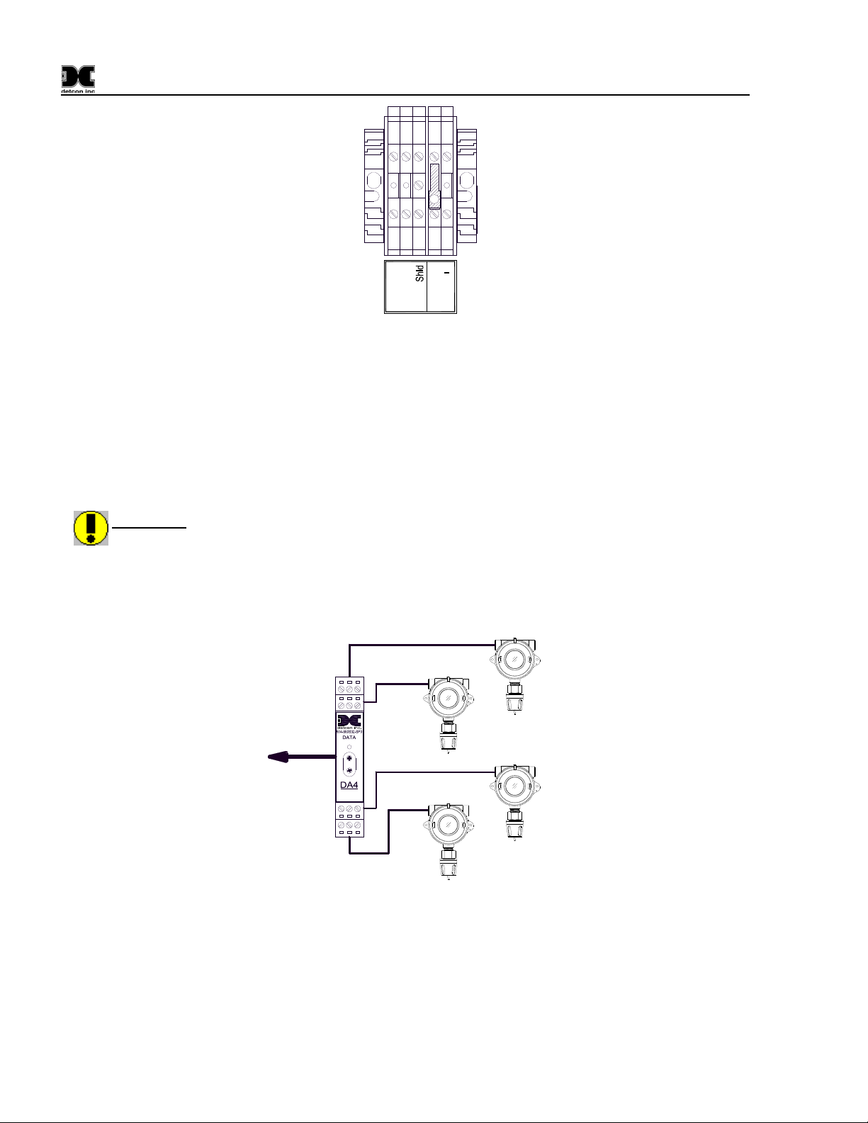
3. For Analog Units (880A), communication is accomplished by using Detcon DA4 modules and the RS-
485 Modbus™. The 4-20mA sensors are directly connected to the DA4 modules, while the DA4
modules are connected via the RS-485 Modbus™ to the 880 PLC (Figure 9). All DA4’s are externally
mounted and require an external power source. The correct setup of the DA4’s is covered in Section
4.3 880 Setup.
WARNING
to no more than 4Amps maximum (96 Watts). This equates to 7 DA4 Modules with 28 attached
sensors and/or field devices. Care should be taken to insure that the total current of equipment
utilizing this power does not exceed this 4Amp rating, as this may cause detrimental damage to the
unit and will void the warranty. An External Power Source should be used to power any and all
components that exceed this rating.
: If the 24VDC output is used to power external components the output is to be restricted
Sensor 4
RS-485 to 880
COMM
M
S
D
L
S
D
4-20mA
INPUT
Sensor 3
Typical Sensors
Sensor 2
Sensor 1
Figure 9 Typical Analog Sensor Wiring
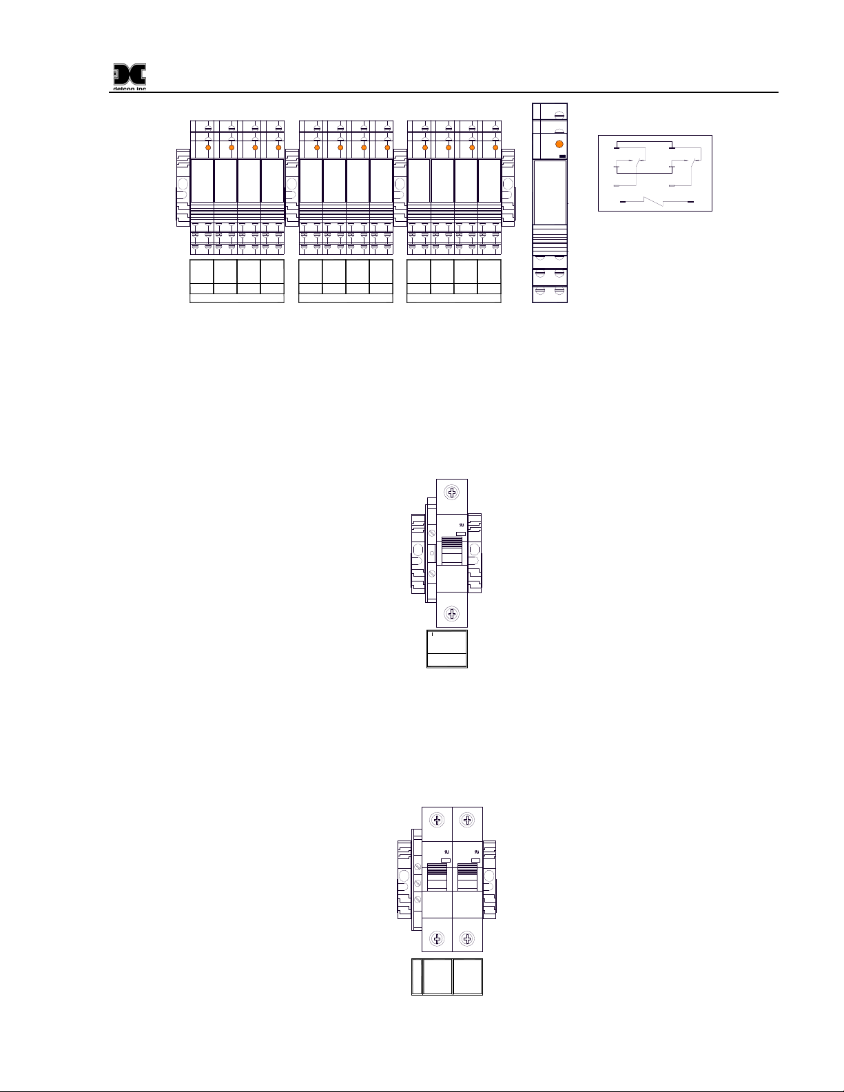
4. Connect external annunciators to the relay terminals provided in the enclosure. The Alarm Relays are
set up in banks (BANK 1, BANK 2, and BANK 3). Each bank consists of a set of relays labeled
“FLT” (Fault), “ALM1” (Alarm 1), “ALM2” (Alarm 2), and “ALM3” (Alarm 3). Each relay has a set
of dry contacts labeled “12-COM” Common, “11-NC” Normally Closed, and “14-NO” Normally
Open (Figure 10). Wire annunciators to the appropriate bank and alarm/fault relay.
880-N4X Instruction Manual Rev. 0.0 Page 8 of 36
Page 13
880-N4X
A1+
A2-
11 11
14 14
12 12
A2 (-) A1 (+)
NC - Normally Closed
NO - Normally Open
COM - Common
11-NC
14-NO
12-COM
FLT
11-NC
14-NO
12-COM
ALM1
BANK 1
11-NC
14-NO
12-COM
ALM2
11-NC
14-NO
12-COM
ALM3
11-NC
14-NO
12-COM
FLT
11-NC
14-NO
12-COM
ALM1
BANK 2
11-NC
14-NO
12-COM
ALM2
11-NC
14-NO
12-COM
ALM3
11-NC
14-NO
12-COM
FLT
11-NC
14-NO
12-COM
ALM1
BANK 3
11-NC
14-NO
12-COM
ALM2
11-NC
14-NO
12-COM
ALM3
24
V
11
11
14
14
12
12
Figure 10 Alarm Relay Connections
5. If applicable, connect a 24VDC Battery Backup or Auxiliary 24V source to the terminal blocks
labeled “24VDC INPUT” (24V+ and 24V–) (Figure 11).
NOTE: This input should be capable of supplying at least 7 Amp s at 24VDC in order for the unit to
operate properly. Insufficient current capabilities may cause detrimental damage to the unit and will
void the warranty.
C10
WMS1C10
240V-
10000
I ON
24V -
24V +
24VDC
INPUT
Figure 11 Typical 24VDC Input Connections
6. Connect 110-220VAC input to the Fuse Block labeled “VAC (L1)” in the lower left of the enclosure.
Connect Neutral (or L2) to terminal labeled “NEU (L2)” and Ground to the Green/Yellow terminal
labeled “GROUND” (Figure 12). The power supply is able to accept AC input voltages from 100 to
240 volts at 50 or 60Hz.
23
1
C3
C3
WMS1C03
WMS1C03
240V-
240V-
10000
10000
I ON
I ON
Ground
VAC (L1)
NEU (L2)
Figure 12 Typical Input Power connections
880-N4X Instruction Manual Rev. 0.0 Page 9 of 36
Page 14
880-N4X
3.1 Initial Power Checks
Upon completion of all field wiring, apply power to the 880 by: 1) setting both the AC Circuit Breakers and
DC Circuit Breakers to “ON”, 2) pushing the “POWER ON/OFF” switch on the front panel. The “POWER”
LED should illuminate. If all connections have been made properly, the “FAULT” and “ALARM” LED’s
should not be illuminated. The unit will go through a brief initialization and display the “Main Screen”
(Figure 26, Section 4.3). The “AC” box on the display should be green showing that AC is attached to the
unit. The “USB” box should be gray to indicate that no USB drive is attached.
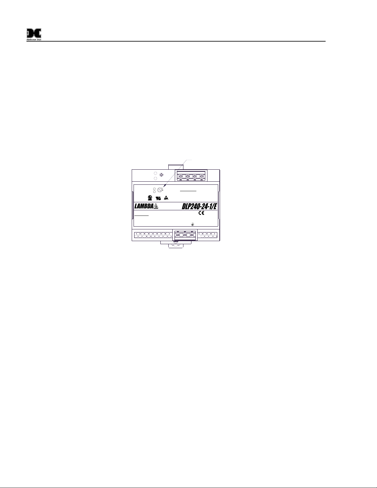
Measure the voltage across the power supply output (V+ and V-). The reading should be 24 ±2.4VDC. If the
voltage is out of tolerance, make adjustments using the 24VDC Adjustment Potentiometer on the 24Volt
Power Supply.
24VDC Adjust
DC ONDC ON
V.ADJV.ADJ
ALMALM
RR
US
US
C
C
USC
USC
45JB
Made in China
Input DetailsInput Details
100-240VAC 3.5A Maximum
100-240VAC 3.5A Maximum
Power Factor Corrected
Power Factor Corrected
Frequency : 50/60HzFrequency : 50/60Hz
HH
+V+V+V+V -V-V -V-V
Output DetailsOutput Details
Continuous Loading 24VDC/10AContinuous Loading 24VDC/10A
N
L
Figure 13 24VDC adjustment
3.2 Auxiliary 24VDC Input
If an Auxiliary 24VDC Input is connected to the unit, the voltage may need to be adjusted to insure proper
operation. If the 24VDC input is being used to operate the unit, the source must be able to provide at least
7Amps to insure proper unit operation. The unit utilizes a 10A Circuit Breaker to provide over current
protection.
Measure the voltage across TB3 terminals 4 and 5. This voltage should read above 21.6VDC and below
26VDC.
If the 24VDC input is to be used as a Backup or Auxiliary 24VDC Input, adjustments may be required to
insure that it is below the internal power supply voltage. If the voltage measured across the Power Supply is
lower than the Auxiliary 24VDC Input, the internal power supply will not be used to supply power to the unit.
The Auxiliary 24VDC Input to the unit should be adjusted to at least 0.1-0.15VDC below the unit’s 24V
Power Supply for correct operation. This will insure that the unit does not operate on the Auxiliary 24VDC
Input unit unless the AC power is lost.
3.3 880 Remote Display Installation (Optional)
The Detcon Model 880 Remote Display enclosure is rated NEMA 4X, which is rain tight and suitable for
outdoor locations in electrically non-hazardous environments. The enclosure is equipped with four (4) wallmounting brackets for easy wall mount installations. Care should be given to prevent sharp objects from
880-N4X Instruction Manual Rev. 0.0 Page 10 of 36
Page 15
880-N4X
colliding with the touch screen. The screen can be cleaned with a mild detergent and a lint free cloth. Never
use an abrasive cleaner on the display.
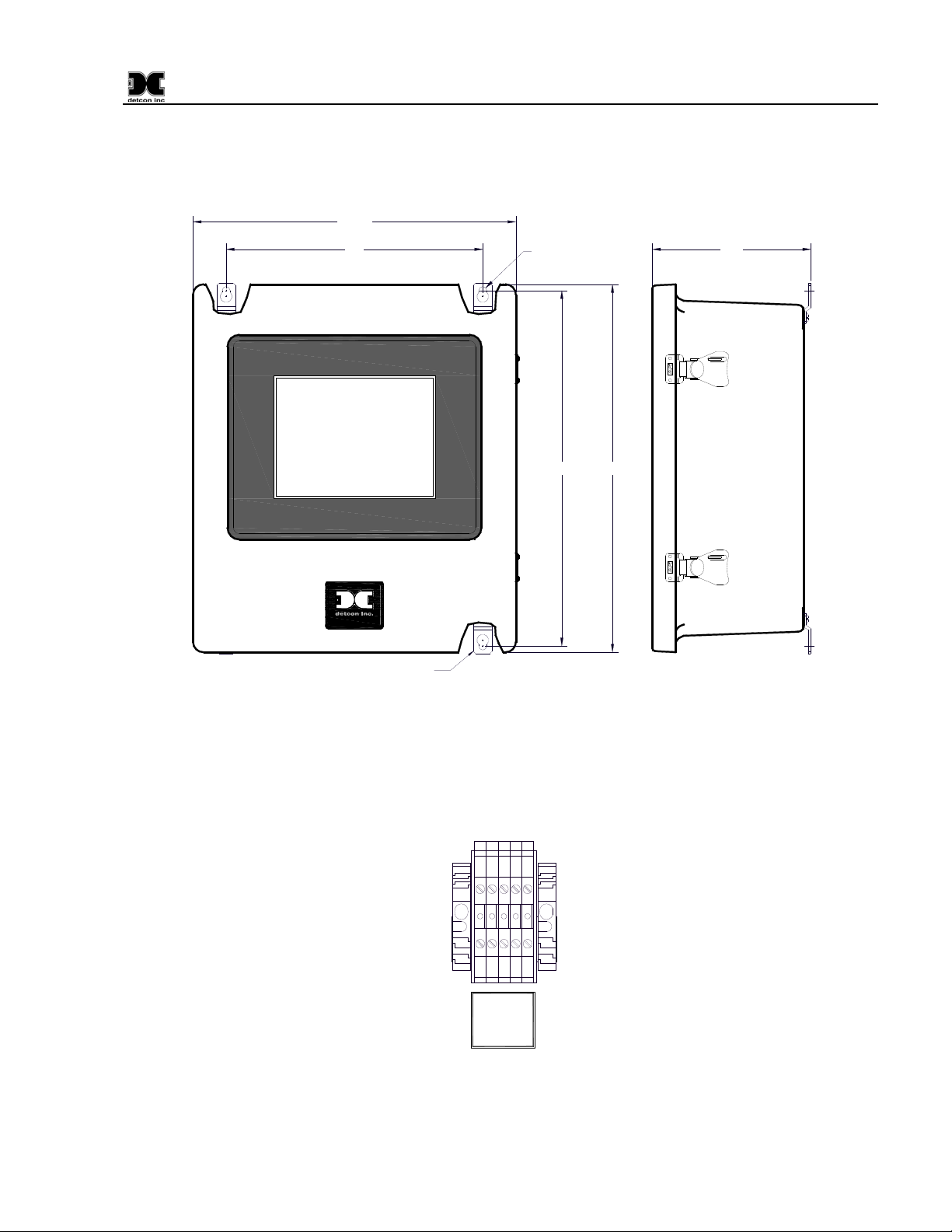
1. Securely mount the 880 Enclosure in accordance with Figure 14.
13.85"
11"
www.detcon.com
Mounting Hardware
Figure 14 Dimensional Overview
Ø0.344"
15.2" 15.75"
6.8"
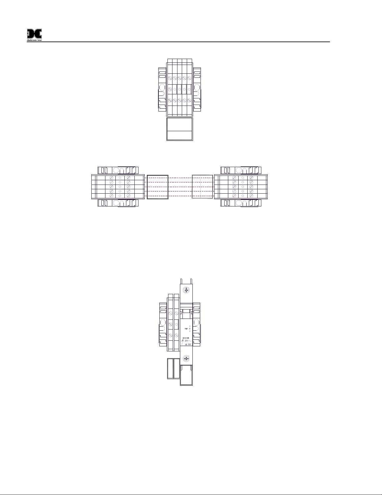
2. Run the serial cable between the Main 880 enclosure and the 880 Remote Display enclosures.
3. Connect the RS-422 Serial communications cable to the terminal blocks labeled “REMOTE
OUTPUT” in the Main 880 enclosure (Figure 15).
0V
TXD-
RXD-
TXD+
RXD+
REMOTE
OUTPUT
Figure 15 Main 880 terminal blocks and connections
4. Connect the RS-422 Serial communications cable to the input terminal blocks inside the 880 Remote
Display labeled “TERMINAL INPUT” as shown in (Figure 16).
880-N4X Instruction Manual Rev. 0.0 Page 11 of 36
Page 16
880-N4X
0V
TXD-
RXD-
TXD+
RXD+
TERMINAL
INPUT
Figure 16 Remote RS-422 connections
TXD+
TXD+
MAIN 880
TXD-
RXD+
RXD+
RXD-
0V
OUTPUT
REMOTE
CUSTOMER SUPPLIED
WIRING
Figure 17 Remote Interconnect Wiring
TXDRXD-
0V
I
N
P
U
T
T
T
X
D
+
E
R
T
X
D
-
M
I
R
X
D
+
N
A
R
X
D
-
L
V
0
REMOTE DISPLAY
5. Connect 110-220VAC input to the Fuse Block labeled “VAC (L1)” in the lower left of the enclosure.
Connect Neutral (or L2) to terminal labeled “NEU (L2)” and Ground to the Green/Yellow terminal
labeled “GROUND” (Figure 18). The power supply is able to accept AC input voltages from 100 to
240 volts at 50 or 60Hz.
1A
I
O
Ground
NEU (L2)
VAC (L1)
Figure 18 Typical Input Power connections
Upon completion of all field wiring, apply power to the Main 880 and the 880 Remote Display. The unit will
go through a brief initialization and display the “Main Screen” (Figure 26). The “AC” box on the display
should be green to show that AC is attached to the unit. The “USB” box will be gray to indicate if no USB
drive is attached.
880-N4X Instruction Manual Rev. 0.0 Page 12 of 36
Page 17
880-N4X
4.0 Setup
4.1 User interface
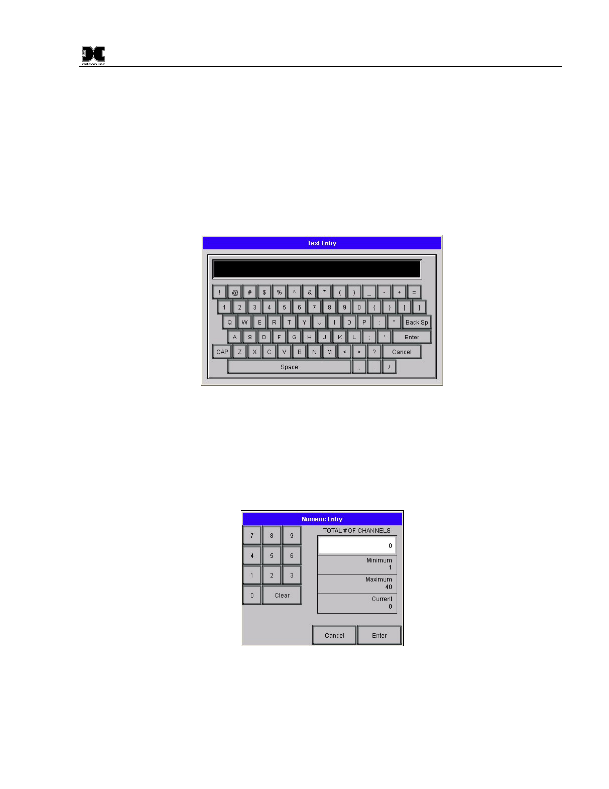
When an alphanumeric or text string is called for, the unit will display an alphanumeric keyboard for the user
to input information (Figure 19). Information typed by the user will be displayed in the box just above the
keyboard. The keyboard is fully functional allowing the user to input spaces, special characters (i.e. ‘*’, ‘&’,
etc.), and make changes between lowercase characters and capitals by using the CAP key. Once the user has
input the correct information, the ‘Enter’ key will transfer the complete string to the appropriate ‘Box’ on the
screen and the alphanumeric keyboard will disappear.
Figure 19 Input Keyboard
When a number is called for, the unit will display a keypad for the user to input the appropriate numeric
response (Figure 20). Information entered by the user will be displayed in the box to the left of the keypad.
Once the user has input the correct information, the ‘Enter’ key will transfer the numeric value to the
appropriate ‘Box’ on the screen and the keypad will disappear. Many keypad entries display a minimum,
maximum, and current box. These boxes show the lower limit, upper limit, and current value of the number
being entered. Numeric entries outside of these restrictions will not be accepted.
Figure 20 Input Keypad
The display screen also contains a number of “buttons”. These “buttons” act as toggle switches that change
state when activated by the wand. These buttons will indicate the change in state by some obvious means such
as a change in color, name, or both (i.e., when changing the state of an alarm from ascending to descending the
button will change from a blue button displaying “ASC” to a gray button displaying “DES”).
880-N4X Instruction Manual Rev. 0.0 Page 13 of 36
Page 18
880-N4X
4.2 Clock and Screen Adjustments
Adjustments to the clock and screen are made entering the display’s Setup Screens. Only the Clock and
Screen adjustments are discussed here. Changing other aspects of the Touch Panel may cause the unit to
operate improperly and should not be attempted.
Access the display’s System Setup Screens by touching the upper left corner of the touch panel with the wand
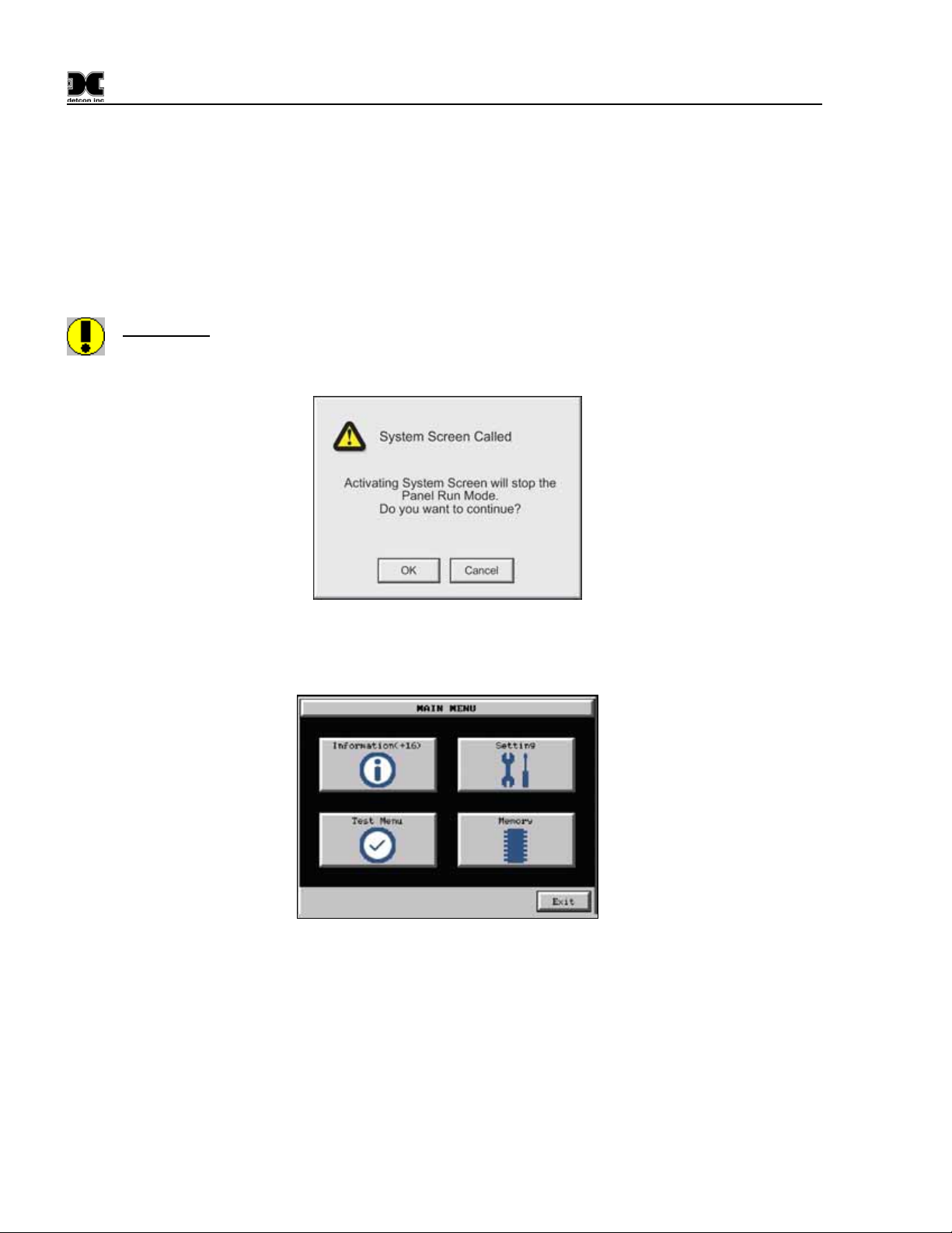
and holding it there for 3-5 seconds. A warning box will appear (Figure 21). If no action is taken within 60
seconds, the display system will return to the Main Screen. To return to the Main Screen select “Exit”.
WARNING:
panel and the PLC will cease.
Selecting OK will stop the PLC driver; therefore, all communication between the touch
Figure 21 Warning Screen
To enter the display’s Setup Screen, select “OK”. The Main Menu will be displayed (Figure 22).
Figure 22 Main Menu
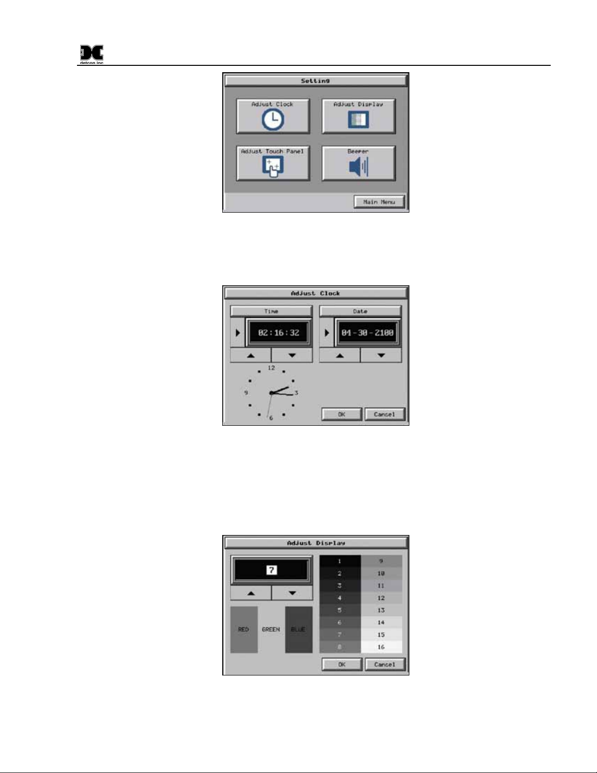
From the Main Menu select the “Setting” button to enter the “Setting” Screen (Figure 23).
880-N4X Instruction Manual Rev. 0.0 Page 14 of 36
Page 19
880-N4X
Figure 23 Screen Settings
From the “Setting” Screen, select the “Adjust Clock” button to adjust the clock (Figure 24) or the “Adjust
Display” button to adjust the Display Screen (Figure 25).
Figure 24 Clock Adjust Screen
To adjust the Time and Date use the arrow keys. Once the correct time and date have been set, select “OK” to
close the screen. Select “Main Menu” to exit the “Setting” screen, and select “Exit” to exit the Setup screens.
To adjust the display use the arrow keys. Once the display has been adjusted, select “OK” to close the screen.
Select “Main Menu” to exit the “Setting” screen, and select “Exit” to exit the Setup screens.
Figure 25 Adjust Display Screen
880-N4X Instruction Manual Rev. 0.0 Page 15 of 36
Page 20
880-N4X
4.3 880 Setup
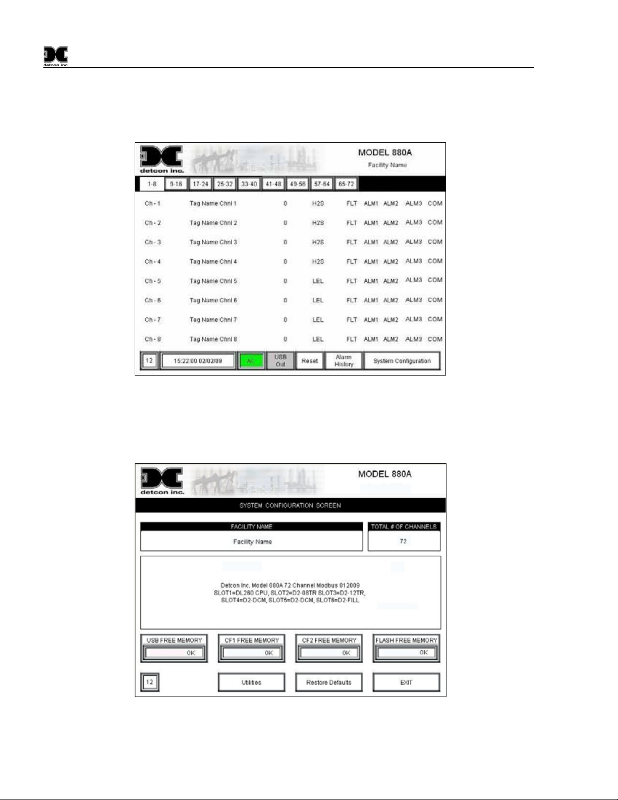
1) From the “Main Screen” (Figure 26), enter the “System Configuration Screen” by touching the “System
Configuration” box with the wand.
Figure 26 Main Screen
2) The display will prompt for a password to enter the 880 “System Configuration Screen”. The default
password is “1234”. Enter the password in the Pop-Up Screen and press enter to continue. This will open
the “System Configuration Screen” (Figure 27 – Analog, Figure 28 - Serial).
Figure 27 Analog Configuration Screen
NOTE: The System Configuration Screens differ only slightly between the Analog and Serial units.
880-N4X Instruction Manual Rev. 0.0 Page 16 of 36
Page 21
880-N4X
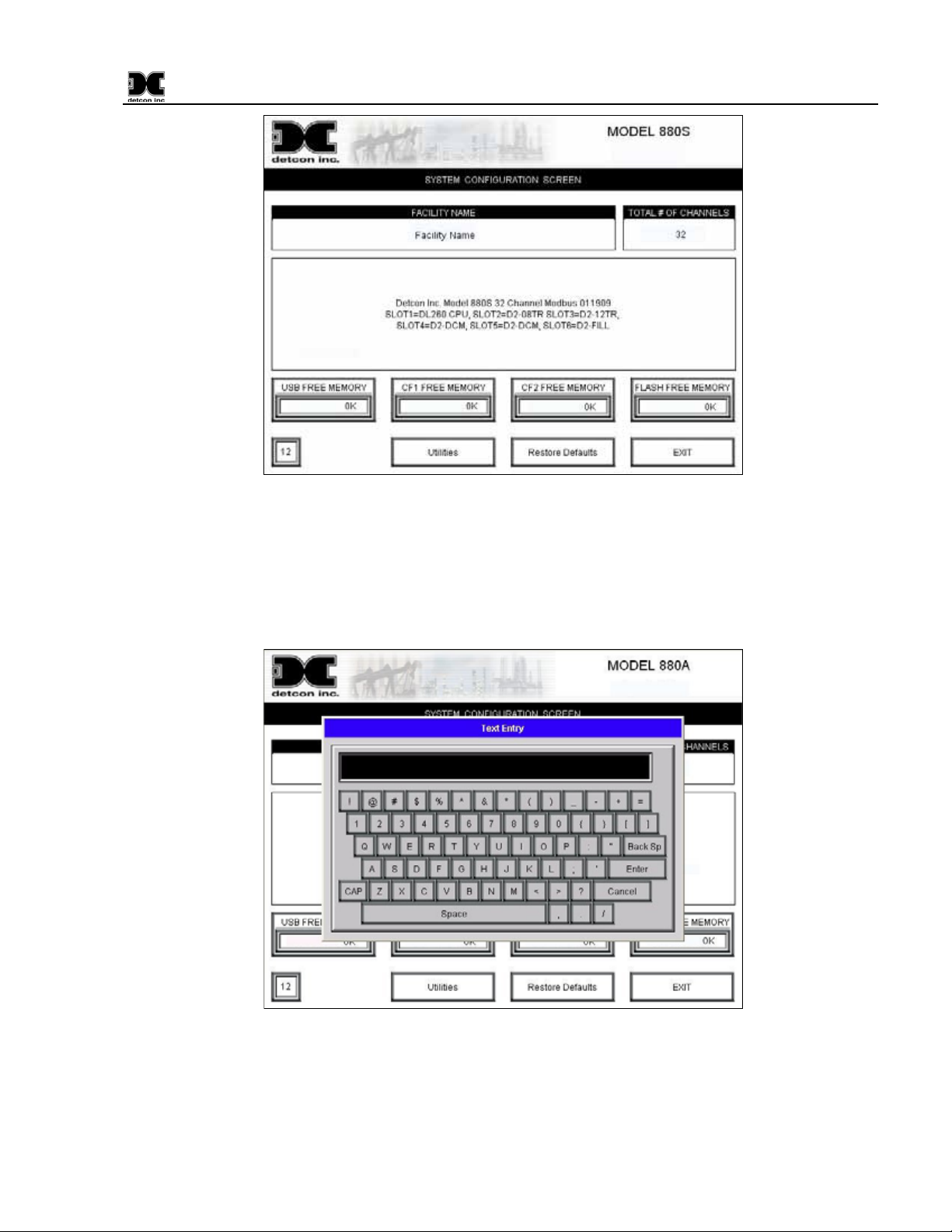
Figure 28 Serial Configuration Screen
3) Use the wand to select the “FACILITY NAME” box. A keyboard will appear to allow input of the facility
name (Figure 29). The facility name can be any alphanumeric string of no more than 40 characters. After
the facility name has been entered, use the ‘ENTER’ key to transfer the string to the “System
Configuration Screen”.
Figure 29 Inputting the Facility Name
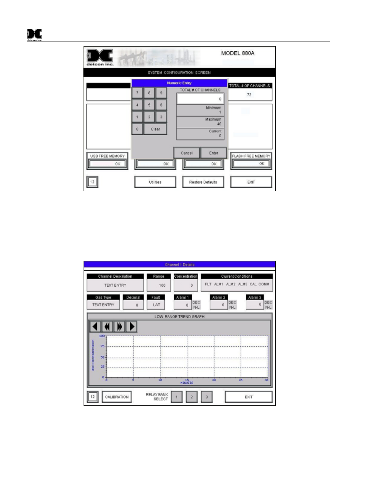
4) Select the “TOTAL # OF CHANNELS” Box and input the number of channels that will be attached to the
unit. For Analog units the number of channels is limited by the number of DA4 Modules connected to the
unit, with a maximum of 72 channels (18 DA4 Modules). For RS-485 units the maximum number of
channels is 32.
880-N4X Instruction Manual Rev. 0.0 Page 17 of 36
Page 22
880-N4X
Figure 30 Inputting the number of channels
) Select the “EXIT” box to exit the “System Configuration Screen” and return to the “Main Screen”.
5
) Each channel must be set up with the correct parameters for each sensor. Using the wand to select a
6
channel from the “Main Screen” will open that channels corresponding “Channel X Details Screen”
(Figure 31).
Figure 31 Channel Detail Screen
) The Model 880 is set up for RS-485 Modbus™ communication. All communications with the sensors are 7
accomplished through the RS-485 communications Protocols. Set up for Serial Sensors (Model 880S) is
different from the set up for Analog Sensors (Model 880A) using the DA4 Modules:
880-N4X Instruction Manual Rev. 0.0 Page 18 of 36
Page 23

880-N4X
erial Sensor Addressing (880S)
S
a) The 880S is set up for RS-485 communication with Serial Sensors. All sensor addresses must start at
01hex and increment sequentially. Serial Sensors should be addressed (in hex) to match the channel
number (in decimal) that they are assigned to. I.E., channel number 1 should be addressed as 01hex,
and likewise channel number 10 should be addressed as 0Ahex. Failure to do so will cause a
communication fault to occur, and the fault will not clear until the addresses are set properly for all
sensors attached to the unit. Refer to Appendix B for Hexadecimal to Decimal conversion table.
nalog Sensor Addressing (880A)
A
a) The 880A is set up for RS-485 communication with Analog Sensors via the Detcon DA4 Module(s).
The DA4 Module addresses must start at 01hex and increment sequentially. I.E., the first DA4 should
have address 01hex, the second 02hex, etc., continuing sequentially until the last DA4. The maximum
number of DA4’s that can be connected to the unit is 18, or 12hex.
) Each DA4 module will accept 4 Analog Sensor inputs; labeled 1-4 on the DA4 (refer to Figure 9).
b
The physical channel number of a sensor corresponds to the DA4 it is connected to, as well as the
sensor input on the corresponding DA4.
xample: If the sensor is connected to input 1 on the DA4 addressed at 01hex, it would be channel 1 on
E
the 880A. If the sensor is connected to input 2 of the same DA4 it would be channel 2 on the 880A.
Continue this sequence for the third and fourth gas channels. Channel 5 would be connected to the second
DA4, addressed at 02hex. A matrix table for the Model DA4 modules would look like this:
880A Ch # DA4 # DA4 Hex Address Sensor Position
1 1 01hex 1
2 1 01hex 2
3 1 01hex 3
4 1 01hex 4
5 2 02hex 1
6 2 02hex 2
7 2 02hex 3
8 2 02hex 4
9 3 03hex 1
… … … …
68 18 1
70 18 12hex 2
71 18 12hex 3
72 18 12hex 4
c
) Continue this addressing scheme until all analog sensors have been correctly identified by the 880A.
8
) Select “Channel Description”. The keyboard will appear, allowing the input of the Channel Tag Name, or
a brief description of the sensor, up to 20 characters maximum.
9
) Select “Gas Type”, and input the gas type of the sensor. (i.e., H2S, LEL, CO2, etc.) Up to 10 characters
maximum.
1
0) Select “Range” and input the range of the Sensor. (i.e. 25, 50, 100, etc.) Note that the input will not allow
the placement of a decimal point, therefore entries of 10 for a unit of 10ppm or 10% should be entered as
100, and likewise entries of 5 for 5ppm or 5% should be entered as 500. To correctly place the decimal
point in the entry, select the “Decimal Place” box and enter the decimal point placement. (i.e., a “Range”
880-N4X Instruction Manual Rev. 0.0 Page 19 of 36
12hex
Page 24

880-N4X
entry of 100 with a “Decimal Place” of 1 provides a range of 10.0, 10ppm or 10%. Likewise, a “Range”
entry of 500 with a “Decimal Place” of 2 provides a range of 5.00, 5ppm or 5%.)
1
1) Select “Fault” to set the Fault as latching or non-latching. When de-activated (gray), the ‘N-L’ button will
cause the Fault to reset itself only when the fault condition is cleared or fixed. When activated (blue), the
“Fault” ‘LAT’ button will cause the Fault to be “Latching” and will not allow the Fault to reset until the
fault condition is fixed or cleared and the reset button is pressed.
1
2) Select “Alarm 1” to set the level at which Alarm 1 will be activated (typically 10% of full range).
1
3) Select “Alarm 2” and set the level at which Alarm 2 will be activated (typically 20% of full range).
1
4) Select “Alarm 3” and set the level at which Alarm 2 will be activated (typically 50% of full range).
1
5) Next to “Alarm 1”, “Alarm 2”, and “Alarm 3”, boxes are two buttons labeled ‘ASC/DES’ and ‘LAT/N-L’
dependent on the current state of the button. When activated, these buttons will turn from gray to blue.
The button labeled ‘ASC/DES’ will set the sensor alarm for ascending (ASC) or descending (DES)
respectively. The button labeled ‘LAT/N-L’ will set the sensor alarm for latching (LAT) or non-latching
(N-L) respectively. Set the appropriate values for each alarm respectively:
a) When activated (blue), the ‘ASC’ button will cause the associated Alarm to activate when the sensor
value rises above the value set for that Alarm (Ascending). When de-activated (gray), the ‘DES’
button will cause the associated Alarm to activate when the sensor value falls below the value set for
that Alarm (Descending). Set Alarm’s 1, 2, and 3 to either ascending or descending.
b
) When activated (blue), the ‘LAT’ button will cause the associated Alarm to be “Latching” and will not
allow that Alarm to reset until the cause is cleared or removed and the Alarm is reset with the reset
button. When de-activated (gray), the ‘N-L’ button will cause the associated Alarm to be reset when
the cause of the alarm is either cleared or removed. Set Alarm’s 1, 2, and 3 to either latching or nonlatching.
1
6) At the bottom of the screen are three boxes labeled “RELAY BANK SELECT”, “1”, “2”, and “3”. These
Bank Selection boxes will assign each sensor to a bank of alarms. Assigning a sensor to a Bank of alarms
allows the operator to create groups of sensor Alarms. When activated (Green) the sensor will be assigned
to the bank selected. I.E., selecting Bank 1 will assign that sensor to Bank 1; therefore, should an alarm
occur, it triggers the appropriate alarm in Bank 1 only.
1
7) Once all parameters for the sensor have been set appropriately, select “EXIT” to return to the Main Screen.
1
8) Proceed through all channels, setting each channel’s parameters to the desired values. When all channels
have been correctly set the unit should be ready for normal operation.
.4 Remote Display Set-up
4
he remote display must be setup to match the main 880. The screens are duplicates of the Main 880;
T
therefore, the setup is accomplished in much the same manner as the main unit.
) From the “Main Screen” (Figure 26), enter the “System Configuration Screen” by touching the “System
1
Configuration” box with the wand.
) The display will prompt for a password to enter the 880 “System Configuration Screen”. The default
2
password is “1234”. Enter the password in the Pop-Up Screen and press enter to continue. This will
open the “System Configuration Screen” (Figure 27 – Analog, Figure 28 - Serial).
880-N4X Instruction Manual Rev. 0.0 Page 20 of 36
Page 25

880-N4X
3) Use the wand to select the “FACILITY NAME” box. A keyboard will appear to allow input of the
facility name (Figure 29). The facility name can be any alphanumeric string
of no more than 40
characters, and should be the same as the Facility Name entered in the Main 880. After the facility name
has been entered, use the ‘ENTER’ key to transfer the string to the “System Configuration Screen”.
4) Select the “TOTAL # OF CHANNELS” Box and input the number of channels that will be attached to the
unit. This number must match the number entered in the Main 880.
5) Select the “Exit” box to exit the “System Configuration Screen” and return to the “Main Screen”.
6
) The “Channel Description”, “Gas Type”, and the range decimal point must be setup in the Remote
Display to match the information used to setup the Main 880. Sensor Range and Alarm info
rmation
should not be altered at the Remote Display. (This information is transferred over from the Main 880).
Use the wand to select a channel from the “Main Screen” and open that channel’s corresponding
“Channel Detail Screen” (Figure 31).
a) Select “Channel Description”. The keyboard will appear, allowing the input of the Channel Tag
Name, or a brief description of the s
ensor, up to 20 characters maximum. The “Channel Description”
here must match the “Channel Description” entered at the Main 880.
b) Select “Gas Type”, and input the gas type of the sensor. (i.e., H2S, LEL, CO2, etc.) Up to 10
characters maximum. The “Gas Type” entered here must match the
“Gas Type” entered at the Main
880.
c) The Range of the sensor is transferred by the Main 880 and should not be changed in the Remote
ay. However, the decimal point must be set for the range to be displayed correctly. Therefore
Displ
ranges of 10 for a unit of 10ppm or 10% will be displayed as 100, likewise entries of 5 for 5ppm or
5% will be displayed as 500. To correctly place the decimal point in the entry, select the “Decimal
Place” box and enter the decimal point placement. (i.e., a “Range” entry of 100 with a “Decimal
Place” of 1 provides a range of 10.0, 10ppm or 10%. Likewise, a “Range” entry of 500 with a
“Decimal Place” of 2 provides a range of 5.00, 5ppm or 5%.)
7) Proceed through all channels, setting each channel’s “Channel Description” and “Gas Type” to that setup
in the Main 880. When all channels have been correctly set-u
p the unit should be ready for normal
operation.
880-N4X Instruction Manual Rev. 0.0 Page 21 of 36
Page 26

880-N4X
5.0 System Operation
The touch screen display serves as the graphic user interface to the system. Maneuvering through the system
screens and accessing data fields is accomplished by touching the wand to the appropriate area, box, button, or
key on the screen. The provided “wand” should be the only instrument used to activate the screen as other
instruments may cause damage to the screen.
5.1 Alarm Indicators
The Main 880 Graphics Display Console contains 5 LED’s, and 1 push button/LED Power Switch on the front
panel. The push button switch turns power on and off to the Main 880.
The "POWER ON"
Main 880 has a Battery Backup and AC Power is lost the “POWER ON
indicate that power is still applied to the unit.
The "NO COMM"
In the case of Serial Sensors this will reflect the sensor that is not communicating properly. In the case of
Analog Sensors that communicate via a DA4 Module, this will be reflected as a blinking “COM” by the
sensors that the DA4 Module is associated with.
The "ALARM 1"
1 set point when Alarm 1 is set for ascending. When the alarm is set to descending the LED will
illuminate when the sensor falls below this set point. The "ALARM 1"
“BANK” a sensor is assigned to, and will illuminate no matter what “BANK” is in an alarm condition.
The "ALARM 2"
2 set point when Alarm 2 is set for ascending. When the alarm is set to descending the LED will
illuminate when the sensor falls below this set point. The "ALARM 2"
“BANK” a sensor is assigned to, and will illuminate no matter what “BANK” is in an alarm condition.
The "ALARM 3"
3 set point when Alarm 3 is set for ascending. When the alarm is set to descending the LED will
illuminate when the sensor falls below this set point. The "ALARM 3"
“BANK” a sensor is assigned to, and will illuminate no matter what “BANK” is in an alarm condition.
The "FAULT"
independently of the “Bank” a sensor is assigned to, and will illuminate no matter what “Bank” is in a
fault condition.
5.2 Main Screen
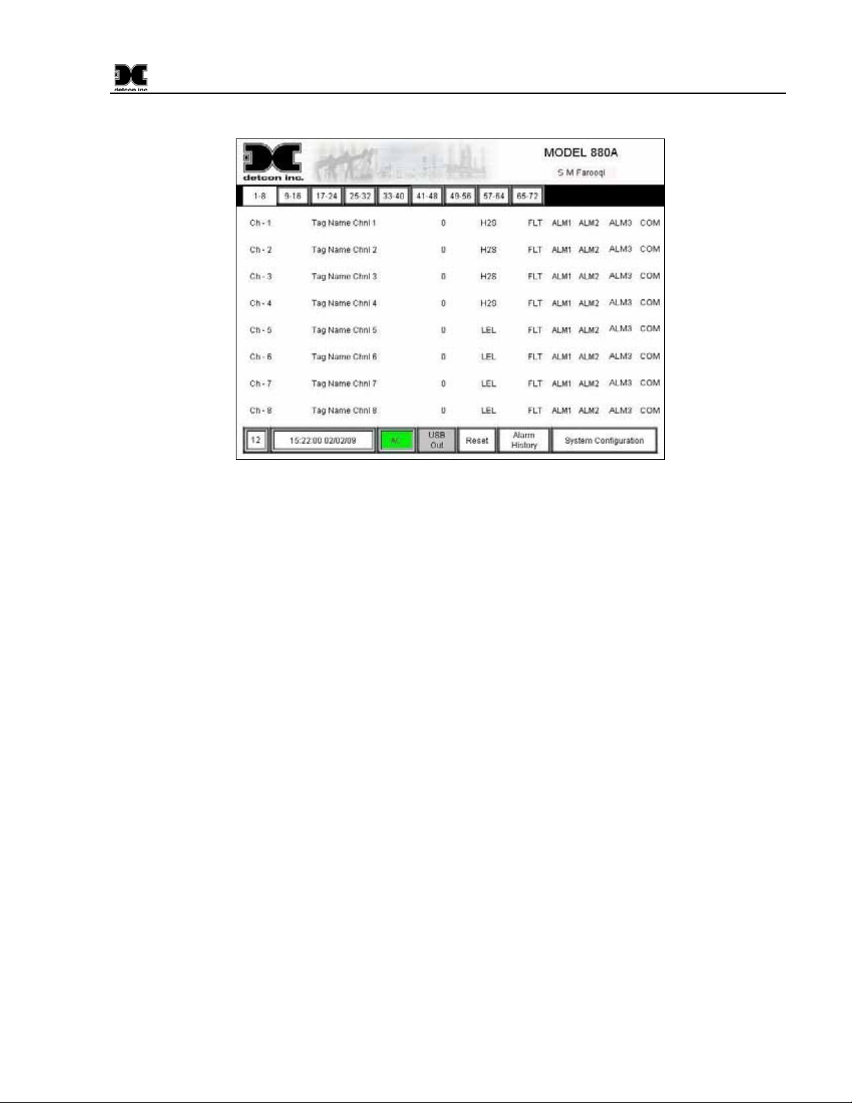
The main screen is the default screen of the unit (Figure 32). The screen displays the first 8 channels, channel
descriptions, current readings, gas type, and sensor status for each channel. If the status of a sensor is such that
the sensor is in an alarm condition, the corresponding “FLT”, “ALM1”, “ALM2”, “ALM3”, or “COM” will
blink to signify that condition. Touching a channel number (Ch-X) will open the corresponding channels
“Channel X Details Screen”. This screen will provide more information on the selected channel.
Near the top left of the screen, just below the Detcon Logo, there will be 2 to 9 selection buttons (Labeled “18,” “9-16,” “17-24,” etc.) dependent on the total number of channels set up in the “System Configuration
Screen.” These buttons represent the pages that display the associated 8 channels; up to page 9 (Channels 65-
72). Selecting any of these buttons with the wand will open the corresponding page to display those
corresponding channels. These pages are all duplicates of the main page, with the exception of the channels
being displayed.
Each channel is displayed as a separate line item on the main screen. Each channel also has an associated
“Channel Detail Screen”. To open a channels detail screen touch the appropriate channel with the wand, this
880-N4X Instruction Manual Rev. 0.0 Page 22 of 36
LED is lit when the Console is powered up using the “Power On/Off” Button. If the
” LED will reamin illuminated to
LED will illuminate when any of the serial inputs are not communicating with the PLC.
LED is illuminated when any one of the sensors in the field, meets or exceeds, the alarm
LED works independently of the
LED is illuminated when any one of the sensors in the field, meets or exceeds, the alarm
LED works independently of the
LED is illuminated when any one of the sensors in the field, meets or exceeds, the alarm
LED works independently of the
LED is illuminated anytime there is a sensor fault. The "FAULT" LED works
Page 27
880-N4X
will open the associated channels detail screen (Section 5.3).
Figure 32 The Main Screen
A row of boxes is located at the bottom of the screen. The second box displays the time and date.
The “AC” box is green when the unit is running on applied AC or if applicable the Auxiliary 24VDC Input.
“USB Out” displays the status of the USB port on the back of the display. When a USB Drive is not installed,
the button will be gray and display “USB Out”. When a USB Drive (USB Memory stick) is installed, the unit
will go through an initialization of the drive and the “USB Out” button will change to green, displaying “USB
Eject”. To eject the USB Drive, touch the button with the wand. When the button turns gray and displays
“USB Out” it is safe to remove the USB Drive from the port.
“Reset” will clear alarms that have been set as latching after the alarm condition has passed. This will only
work when alarms have been set as “Latching”, and only after the alarm condition has been cleared.
“Alarm History” is a select button that will open the “Alarm History Screen” (Section 5.4).
“System Configuration” is a select button that opens the “System Configuration” Screen (Section 4.3).
5.3 Channel X Details Screen
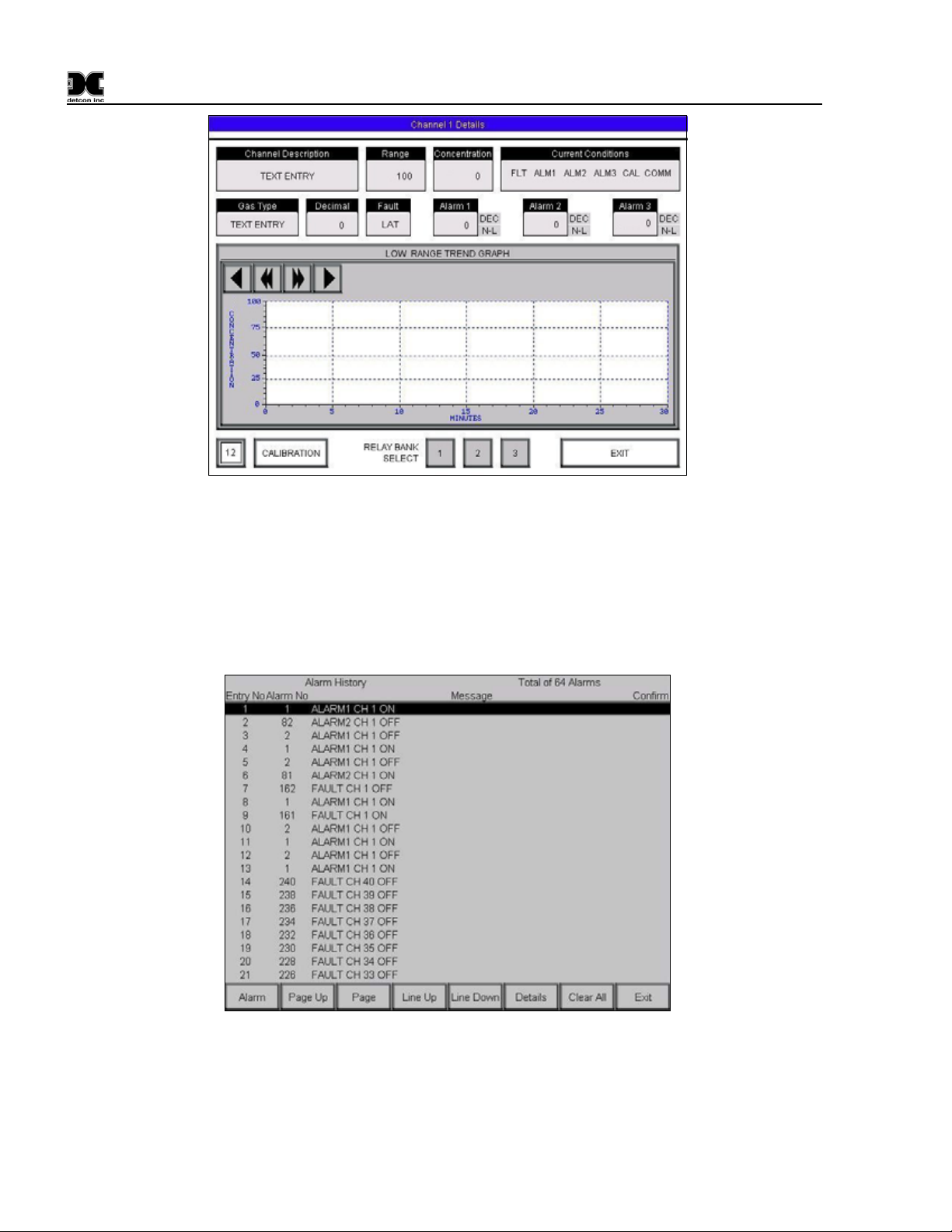
When selected, each channel will open its own detail screen (Figure 33). This screen provides a graphic
representation of the last 30 minutes of the sensor’s activity. The display allows the user to move forward or
backward in the graphic to display activity before or after the displayed time using the arrow keys in the upper
left of the graphic display.
When the sensor goes into a fault or alarm condition the “Current Conditions” box will highlight and blink the
associated fault(s) or alarm(s). Each fault or alarm has a different color for ease in dissociating the condition.
These conditions will remain highlighted and blinking until the conditions to correct them are met. I.E., a
‘CAL’ fault will not clear until the sensor returns to normal operation and, if set to non-latching and ascending,
Alarm 1 will not clear until the “Concentration” falls below the set “Alarm 1 Level.”
880-N4X Instruction Manual Rev. 0.0 Page 23 of 36
Page 28
880-N4X
Figure 33 Channel Details Screen
5.4 Alarm History Screen
When alarms are initiated, the unit stores information about these alarms into memory. If a USB Drive is
installed in the back of the display, this information is written onto the drive for permanent storage (USB
Drive sold separately). The information can also be viewed on the “Alarm History Screen” by using the wand
to select the “Alarm History” button on the Main Screen.
Figure 34 Alarm History Screen
The Alarm History Screen displays Fault and Alarm events throughout operation of the unit (Figure 34).
Navigation buttons located at the bottom of the page allow the user to view all logged data. The view can be
changed from Alarm History to Alarm Count, with a detail button that allows viewing more information on
each event recorded.
880-N4X Instruction Manual Rev. 0.0 Page 24 of 36
Page 29

880-N4X
6.0 Trouble-shooting
6.1 Sensor Faults
The unit is set up such that Sensor faults will set Fault alarms associated with that sensor. If a sensor goes into
a fault condition, that channel will flag a fault. From the “Main Screen” each channel can be quickly viewed
to see which channel is causing the fault. That sensor should be then checked to find the cause of the fault.
Faults are logged in the Alarm History for aid in tracing intermittent sensor problems. Refer to the appropriate
sensor manual for more information on trouble-shooting sensor faults.
6.2 Troubleshooting RS485 Networks
The first step in finding the bad device or several bad devices is to start at the master:
1. Disconnect the data wires (A & B) from the output terminal blocks.
2. Connect a working slave device directly to the master (attached directly to the output terminal blocks)
and make sure that it is functional. If it is not, replace the master’s transceiver chip or board. In the
case of an 880 Controller, this would be the FA-ISOCON Module.
3. Once this is done stop the master from communicating, but do not power it down. This is
accomplished on the Model 880 by unplugging the phone jack connection to the FA-ISOCON
Module.
4. Unplug all of the slave devices from the data bus.
5. Disconnect the working device connected in Step 2, and re-connect the dat a bus wires (A&B) to the
master.
6. Use a voltmeter to measure the voltage across the A and B wires and write the reading down. This
reading should be 400-500 millivolts.
7. Go to the first slave device. Re-connect or plug the device in and measure the voltage across A and B.
Write down the reading. The measurement taken should be 400 to 500 millivolts. If the voltage is not
within the specified range, verify that all devices have been unplugged from the data bus.
8. Unplug the first device and proceed to the next slave device. Record the meter readings. Again the
reading should be 400-500mV. If the reading is not 400-500mV a wiring problem may exist, or the
transmitter may be non-operational.
9. Repeat the procedure with each slave device, recording the readings along the way. If any of the other
readings taken are above or below the first reading by more than 50 millivolts, that unit’s transmitter
or the module should be replaced.
880-N4X Instruction Manual Rev. 0.0 Page 25 of 36
Page 30
880-N4X
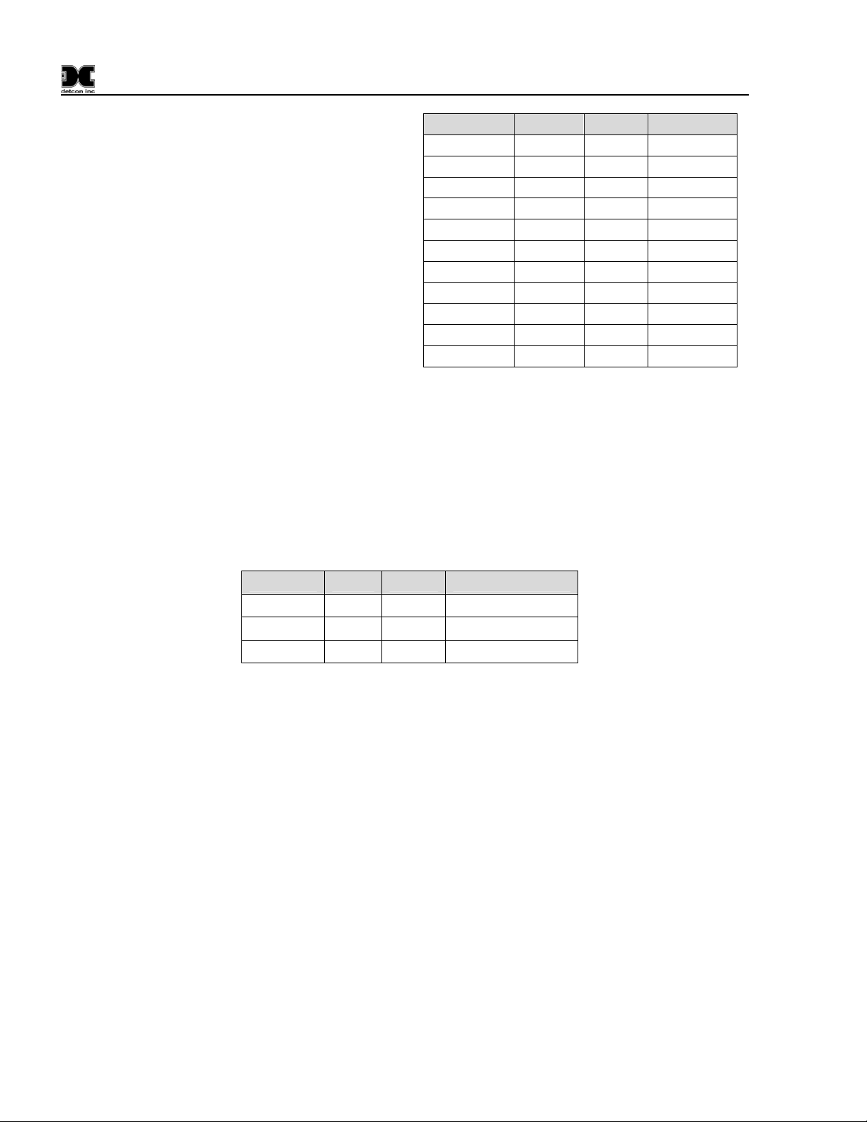
Results similar to those
shown here should be
expected. In this example
slave device 03 and 0B
would need to be changed.
Slave Master MV Difference
ID 01 425 451 26
ID 02 425 430 5
ID 03 425 486 61
ID 04 425 410 -15
ID 05 425 420 -5
ID 06 425 432 7
ID 07 425 422 -3
ID 08 425 415 10
ID 09 425 418 -7
ID 0A 425 440 15
ID 0B 425 310 115
Measuring at the master device between dc common and A, or dc common and B should give a reading of
around 2.5vdc. Remember this is with the power on, but with no communication taking place.
Another method of troubleshooting is to enable the communications and remove all the slaves. Proceed to
plug 1 slave in and see if communication is good. If so, plug in the next slave and check again.
Repeat this with each slave until all of the slaves are plugged in or one of the slaves takes the data bus down.
The following table consists of recommended cables and their specifications from Belden. These cables are
designed with RS-485 in mind and should be used for RS-485 data buses.
Belden# pairs AWG Impedance
9841 1 24 120ohm
9842 2 24 120ohm
8132 2 28 120ohm
The root cause of many RS-485 communication problems can be traced back to incorrect cabling, incorrect
cable and wire types, and the use of incorrect wiring schemes. It is easier to avoid these problems by
following a few simple guidelines:
9 Use good wiring schemes (refer to Appendix A).
9 Use recommended cables.
9 Properly connect data lines and shields.
9 Insure proper termination of data lines.
9 Use isolated repeaters to avoid grounding problems.
880-N4X Instruction Manual Rev. 0.0 Page 26 of 36
Page 31

880-N4X
7.0 Spare Parts
Recommended spare parts list:
Detcon Part # Description
995-321091 CPU Replacement Battery
995-321297-000 PLC Relay Module,
995-323220-100 Communications Module
995-508803-500 Isolated Network Adapter Module
360-DLP240-024 24VDC 240Watt Power supply
347-SSP000-00A Stylus for Touch Screen Display
330-296762-000 24VDC SPST Din-Rail Mounted Relay
0300 3Amp 3AG Slo-Blo Fuse
Include Detcon part number when ordering spare parts.
8.0 Warranty
All warranties are FOB the Detcon factory. Should any product fail to perform in accordance with published
specifications within the warranty period, return it freight pre-paid to Detcon Inc., 3200 Research Forest Drive
Suite A-1, The Woodlands, Texas 77381 for necessary repairs.
Detcon Inc., as manufacturer, warrants each new PLC Graphic Control Unit to be free from defects in material
and workmanship under intended normal use for a period of one year. The warranty period begins on the date
of shipment to the original purchaser and ends one year thereafter.
880-N4X Instruction Manual Rev. 0.0 Page 27 of 36
Page 32
880-N4X
Appendix A
RS-485 System Integration Wiring
RS-485 is a generic electrical specification only. It does not specify connector types, protocols, or cable type.
It is the responsibility of the installer to provide a correct physical installation for the RS-485 network to
function properly.
RS-485 is very inexpensive and inherently rugged, allowing multiple devices to communicate over a single
twisted pair of wires. Detcon has chosen to implement the Modbus™ protocol using the RS-485 electrical
specification.
RS-485 is a two way half-duplex data bus made up of a transceiver (transmitter and receiver). In its simplest
form, one transceiver is located on each end of a twisted pair cable of up to 4,000 feet maximum. Data can be
sent in either direction, but can only be sent in one direction at a time.
The specification allows for the connection of up to 40 unit loads (UL’s) to the twisted pair. An older
transceiver chip would have represented 1 UL. Connection of more than 40 UL’s to the bus will limit the
drivers and cause attenuation of the signal, thus preventing the system from operating properly.
Since RS-485 allows multiple devices to be connected to the bus, wiring is not as straightforward as it is in a
bus with only 2 devices. The best wiring scheme is the daisy-chain connection from device 1 to device 2 to
device 3 to device n. All devices that tap into the bus should not be at the end of long stubs, branches, or ttaps. A true daisy-chain has direct wiring between devices with no minor branches.
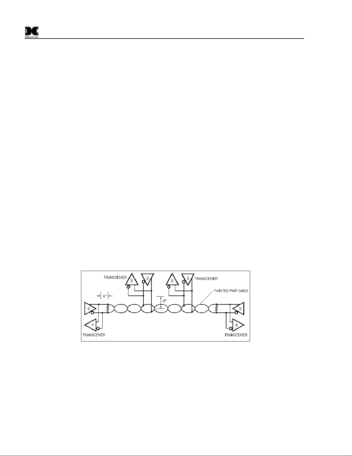
Detcon equipment contains four wiring terminals for RS-485 connections. Two for A(+) and two for B(-). All
connections should be made directly to these. Figure 3.1 shows an electrical representation of a simple RS485 bus with 4 transceiver chips.
Figure 35 RS-485 Bus with 4 transceiver chips
The use of a daisy-chain connection will perform the best in all applications given the bus is properly
terminated. The RS-485 standard specifies the transceiver characteristics only, not the interconnection of the
transceivers themselves. Depending on the environment, distance and other factors it is possible to connect
transceivers using flat cable, twisted pair cable, even PCB traces. However, for the most reliable data transfer
in industrial environments, shielded twisted pair is required. Wiring of 24 AWG is highly recommended, but
18 to 28AWG can be used.
880-N4X Instruction Manual Rev. 0.0 Page 28 of 36
Page 33
880-N4X
The characteristic impedance of the cable must be between 100 to 120 ohms. Twisted pair is used because if
the cable does run near a noise source both conductors will pick up the same amount of noise; therefore,
effectively canceling it out.
Incorrect Wiring Schemes
Among the biggest problems with an RS-485 bus is the use of incorrect wiring schemes mixed with improper
or no line termination.
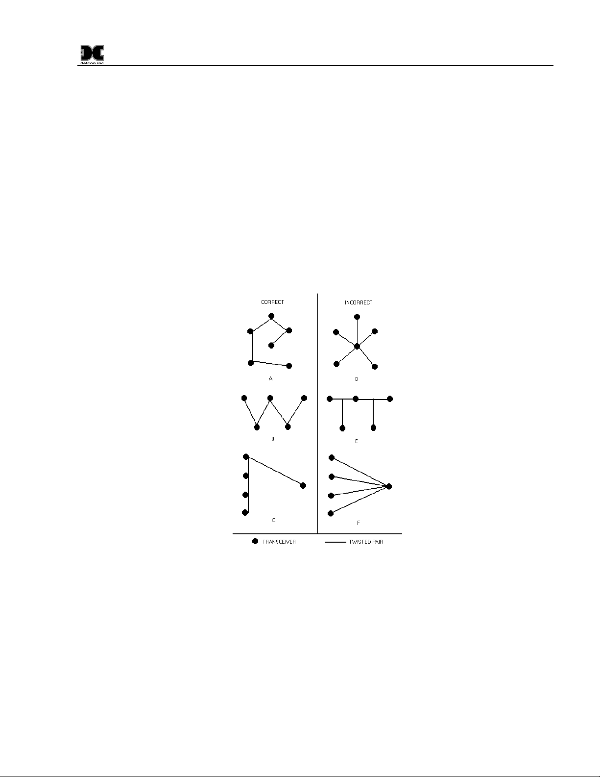
Most existing installations do not have wire runs in a daisy-chain like fashion; instead, wire runs typically
originate from a central point and run to different devices in a star-like pattern. This is a very undesirable way
to wire an RS-485 bus. The chances of problem free operation over the life of the equipment decreases
dramatically the further you stray from a straight daisy-chain wiring scheme. The bus needs to be terminated
at each end of the cable run to operate ideally. Other wiring schemes introduce multiple “cable ends” making
it impossible to balance the lines. Wiring as in Figure 36 (A, B & C) would provide reliable data flow.
Figures D, E & F could possibly work, but would require many repeaters and an experience worker with RS485 communications and networks knowledge to achieve implementation.
Figure 36 Correct and incorrect wiring schemes
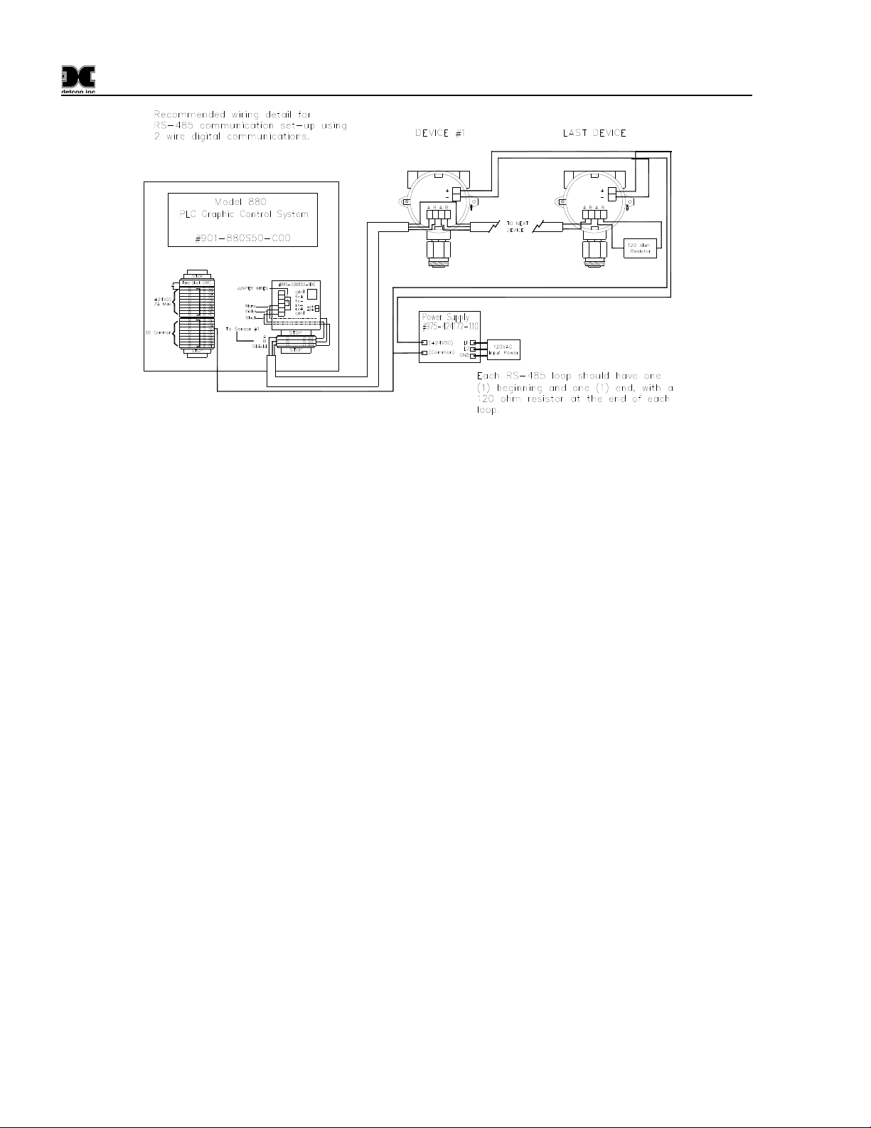
Figure 37 shows a typical RS-485 communication setup using 2-wire digital communication. Each RS-485
loop should have (1) beginning and (1) end, with a 120-ohm resistor at the end of each loop.
880-N4X Instruction Manual Rev. 0.0 Page 29 of 36
Page 34
880-N4X
Figure 37 Recommended RS-485 communications set-up
Grounding
Another problem that can occur with RS-485 is incorrect grounding. Neither one of the two conductors in the
cable is ground. Both of the conductors are supplying a current to maintain a voltage level relative to an
external reference. A third conductor must be supplied to establish a reference through earth ground.
RS-485 is specified be able to work normally with a ±7V ground potential difference and survive ±25V surges.
In most applications, the equipment is powered from its own DC power supplies. This is good as long as the
supplies are located in the same physical location, and the DC commons are tied together and tied to earth
ground.
Problems occur when part of the data bus is powered by one supply and the second part of the bus is powered
by a power supply located elsewhere. In this case, earth ground is being relied upon to be the reference
between the two sections of the bus. If noise is induced onto the earth ground of one power supply and not the
other, data errors may occur. This is even more likely to occur when the distance between ground references
is large. A solution to this problem is to install an isolated repeater into the data bus to isolate the grounds
from each other, thus enabling the bus to use only one of the two references.
Isolated Repeaters
Repeaters can play many rolls in the implementation of an RS-485 data bus. Repeaters can: 1) Extend the
distance if needed to go further than 4000 feet. 2) Allow for the addition of more devices to the bus. 3)
Increase signal strength and integrity. 4) Solve grounding problems and solve some of the problems that occur
when an incorrect wiring scheme is implemented.
A repeater consists of two transceivers working together. One transceiver is connected to the main data bus
and the other transceiver connects to the remainder of the devices as it creates a new and separate data bus.
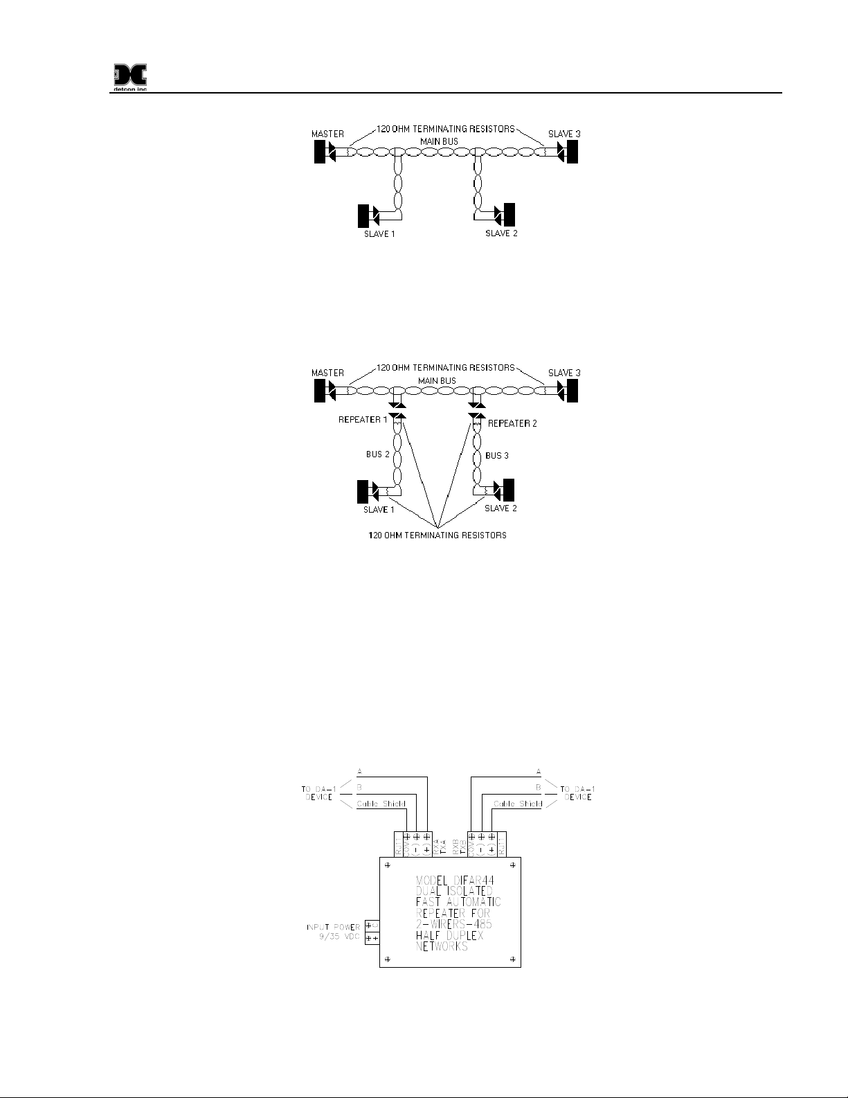
Figure 38 depicts a data bus that implements an undesirable branched wiring scheme. Depending on the
length of the taps of slave 1 and slave 2, they may or may not communicate properly back to the master. Long
lengths of cable to slaves 1 and 2 create four ends to the cable instead of two, which cannot be balanced with
the two terminating resistors on the extreme ends. Without a balanced bus, the long taps of slave 1 & 2 will
introduce reflections to the signal that can lead to problematic operation in the field. These problems can be
very hard to diagnose, isolate, and fix.
880-N4X Instruction Manual Rev. 0.0 Page 30 of 36
Page 35
880-N4X
Figure 38 Unbalanced Data Bus
The addition of 2 repeaters (Figure 39) can solve this problem. The repeaters look like short stubs to the main
bus, and at the same time they create 2 new buses that have all the same characteristics as the main bus. Each
leg must have termination resistors to balance the new data bus.
Figure 39 Data Bus using two repeaters
Be sure to check the equipment being installed. Some manufacturers include a built-in terminating resistor
that can be selected by a jumper or dipswitch. Detcon Model 880 has such a jumper located on the FA-isonet
card. The jumper is labeled “120 ohm Term.”
Detcon 600 series gas sensors and DA1 modules do not include this resistor, and therefore, if one of these
devices is the last on the RS-485 bus, a discrete 120 ohm resistor should be placed across the “A” and “B”
terminals on the connector board. Figure 40 illustrates the wiring scheme of a repeater when used in a wiring
bus with DA-1 devices.
Figure 40 Repeater wiring diagram
880-N4X Instruction Manual Rev. 0.0 Page 31 of 36
Page 36
880-N4X
Device Hook-Up
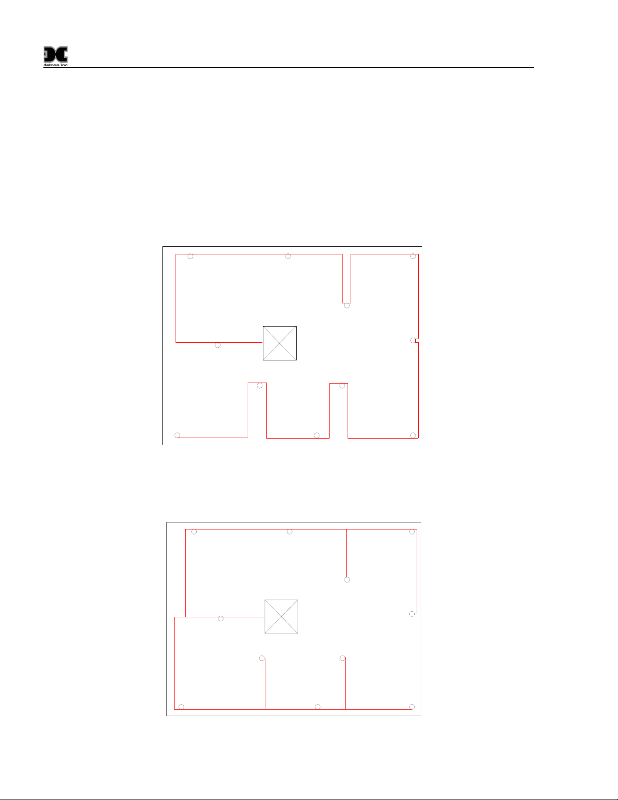
Installation should begin by deciding where devices will be located and how the connections between devices
and the master will be established. The ideal scenario would look like Figure 41. The example shows the 880
Controller connected to 11 slave devices using a daisy-chain wiring scheme. This would require 2 different
twisted pair cables, one pair for power, and the other for the RS-485 data bus.
Connections would be point-to-point starting at the master and running to the last slave. The RS-485 data
cable should come into the sensor enclosure and be connected to the A & B terminals. The next segment of
cable should also connect to the A & B terminals and leave the enclosure headed for the next device. The
shields must be tied together inside the enclosure and not allowed to short to any other wires or surfaces. The
shield should be connected only inside the Model 880 cabinets to the shield terminal. The Rt label in the
drawing shows where the termination resistors would be installed.
01 02
Control Room
Rt
09
0a
08
Rt
04
0b
07 06
03
05
Figure 41 Daisy Chain wiring diagram
Daisy Chain Wiring is ideal, although wiring may already exist or the wiring cannot be run this way for some
reason. Figure 42 shows a more realistic wiring situation that may occur.
01 02
03
Control Room
09
0a 0b
08
04
05
0607
Figure 42 Unbalanced Data Bus
880-N4X Instruction Manual Rev. 0.0 Page 32 of 36
Page 37
880-N4X
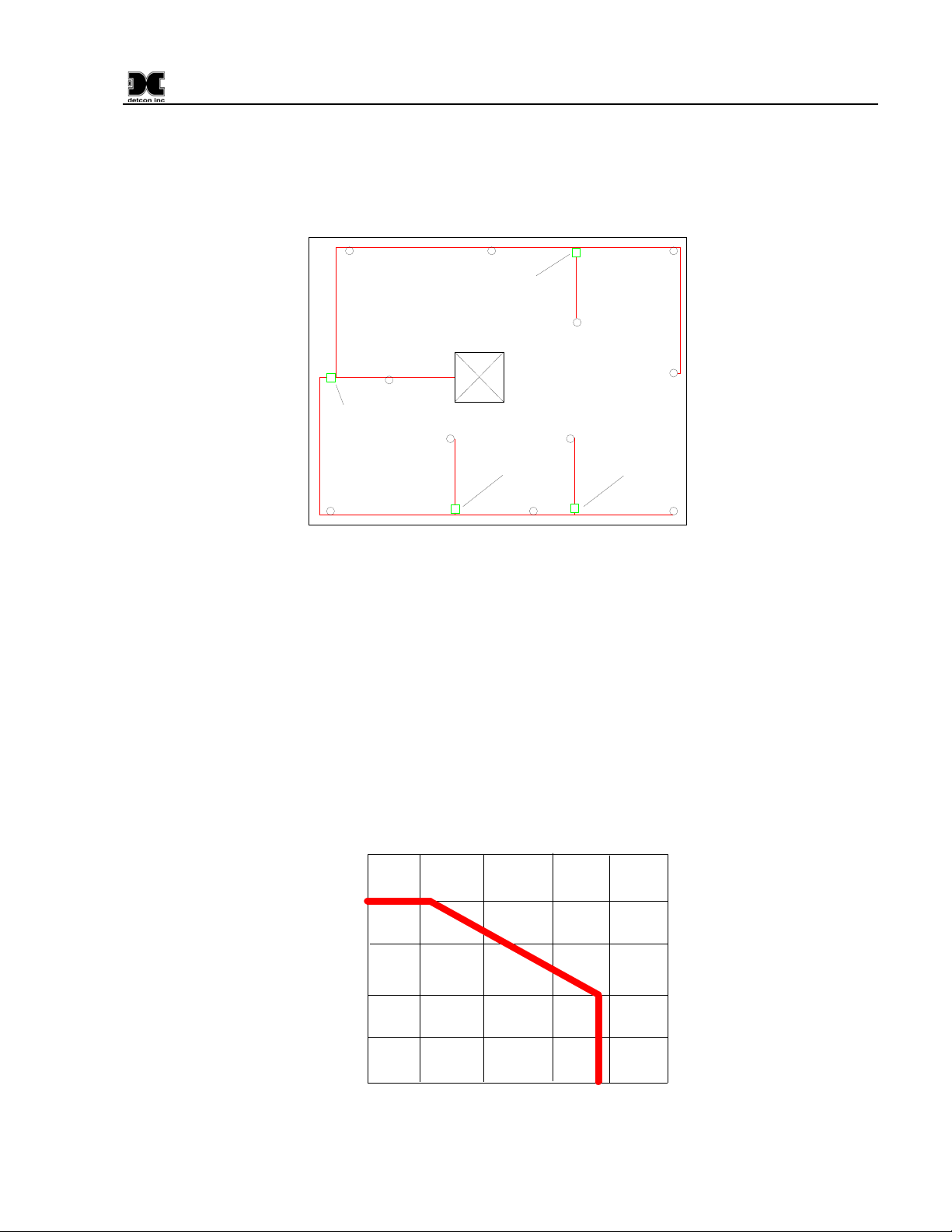
In this case it is impossible to balance the data bus because there is no distinct beginning or end to the cable
run. The best way to make this type of installation successful is to install repeaters in a few key areas as
shown in Figure 43. Repeaters are used to eliminate the t-taps or stubs, which can cause communication
problems. The location and number of stubs will dictate where repeaters need to be installed. Four repeaters
are installed to eliminate the stubs.
01 02
Rt
Rt
08
09
repeater #1
repeater #2
Control Room
Rt
0a
repeater #3
Rt
07 06
Rt
Rt
04
Rt
0b
Rt
03
Rt
05
repeater #4
Rt
Figure 43 Four repeater Data Bus
Notice there are 5 different data buses that make up the communications network. The first one consists of the
master located in the control room, device 09, repeater #1, device 01, device 02, repeater #2, device 03, and
device 05. Notice the termination resistors at the beginning and end of this bus section. The second bus starts
at repeater #2. It consists of the repeater and device 04. Since this is a new bus, it has terminating resistors at
each end. The third bus starts at repeater #1. It includes device 08, repeater #3, device 07, repeater #4, and
device 06. It also has its own resistors. The fourth bus starts at repeater #3 and consists of the repeater, d evice
0A, and the terminating resistors. The fifth bus starts at repeater #4 and consists of the repeater, device 0B,
and termination resistors. This configuration isolates all of the t-tap stubs. This configuration should function
properly as long as the wire type and proper distances are observed.
The following chart shows an approximation of wire length vs. data speed. Detcon operates its equipment at
19,200bps (baud) and lower.
100 mbps
10 mbps
1 mbps
100 kbps
10 kbps
1 kbps
0 ft
10 ft
100 ft
1000 ft
5000 ft
10000 ft
Figure 44 wire length vs. data speed
880-N4X Instruction Manual Rev. 0.0 Page 33 of 36
Page 38

880-N4X
Appendix B
Hexadecimal Table
ID# SW1 SW2 ID# SW1 SW2 ID# SW1 SW2 ID# SW1 SW2 ID# SW1 SW2 ID# SW1 SW2
none
10 0 A 53 3 5 96 6 0 139 8 B 182 B 6 225 E 1
11 0 B 54 3 6 97 6 1 140 8 C 183 B 7 226 E 2
12 0 C 55 3 7 98 6 2 141 8 D 184 B 8 227 E 3
13 0 D 56 3 8 99 6 3 142 8 E 185 B 9 228 E 4
14 0 E 57 3 9 100 6 4 143 8 F 186 B A 229 E 5
15 0 F 58 3 A 101 6 5 144 9 0 187 B B 230 E 6
16 1 0 59 3 B 102 6 6 145 9 1 188 B C 231 E 7
17 1 1 60 3 C 103 6 7 146 9 2 189 B D 232 E 8
18 1 2 61 3 D 104 6 8 147 9 3 190 B E 233 E 9
19 1 3 62 3 E 105 6 9 148 9 4 191 B F 234 E A
20 1 4 63 3 F 106 6 A 149 9 5 192 C 0 235 E B
21 1 5 64 4 0 107 6 B 150 9 6 193 C 1 236 E C
22 1 6 65 4 1 108 6 C 151 9 7 194 C 2 237 E D
23 1 7 66 4 2 109 6 D 152 9 8 195 C 3 238 E E
24 1 8 67 4 3 110 6 E 153 9 9 196 C 4 239 F F
25 1 9 68 4 4 111 6 F 154 9 A 197 C 5 240 F 0
26 1 A 69 4 5 112 7 0 155 9 B 198 C 6 241 F 1
27 1 B 70 4 6 113 7 1 156 9 C 199 C 7 242 F 2
28 1 C 71 4 7 114 7 2 157 9 D 200 C 8 243 F 3
29 1 D 72 4 8 115 7 3 158 9 E 201 C 9 244 F 4
30 1 E 73 4 9 116 7 4 159 9 F 202 C A 245 F 5
31 1 F 74 4 A 117 7 5 160 A 0 203 C B 246 F 6
32 2 0 75 4 B 118 7 6 161 A 1 204 C C 247 F 7
33 2 1 76 4 C 119 7 7 162 A 2 205 C D 248 F 8
34 2 2 77 4 D 120 7 8 163 A 3 206 C E 249 F 9
35 2 3 78 4 E 121 7 9 164 A 4 207 C F 250 F A
36 2 4 79 4 F 122 7 A 165 A 5 208 D 0 251 F B
37 2 5 80 5 0 123 7 B 166 A 6 209 D 1 252 F C
38 2 6 81 5 1 124 7 C 167 A 7 210 D 2 253 F D
39 2 7 82 5 2 125 7 D 168 A 8 211 D 3 254 F E
40 2 8 83 5 3 126 7 E 169 A 9 212 D 4 255 F F
41 2 9 84 5 4 127 7 F 170 A A 213 D 5
42 2 A 85 5 5 128 8 0 171 A B 214 D 6
0 0 43 2 B 86 5 6 129 8 1 172 A C 215 D 7
1 0 1 44 2 C 87 5 7 130 8 2 173 A D 216 D 8
2 0 2 45 2 D 88 5 8 131 8 3 174 A E 217 D 9
3 0 3 46 2 E 89 5 9 132 8 4 175 A F 218 D A
4 0 4 47 2 F 90 5 A 133 8 5 176 B 0 219 D B
5 0 5 48 3 0 91 5 B 134 8 6 177 B 1 220 D C
6 0 6 49 3 1 92 5 C 135 8 7 178 B 2 221 D D
7 0 7 50 3 2 93 5 D 136 8 8 179 B 3 222 D E
8 0 8 51 3 3 94 5 E 137 8 9 180 B 4 223 E F
9 0 9 52 3 4 95 5 F 138 8 A 181 B 5 224 E 0
880-N4X Instruction Manual Rev. 0.0 Page 34 of 36
Page 39

880-N4X
Appendix C
Drawings and Diagrams
1. 880-N4X Dimensional Overview
2. 880-N4X Component Layout
3. 880-N4X Wiring Diagram
880-N4X Instruction Manual Rev. 0.0 Page 35 of 36
Page 40

880-N4X
Page intentionally blank
Shipping Address: 3200 A-1 Research Forest Dr., The Woodlands Texas 77381
Mailing Address: P.O. Box 8067, The Woodlands Texas 77387-8067
Phone: 888.367.4286, 281.367.4100 • Fax: 281.292.286 0 •
880-N4X Instruction Manual Rev. 0.0 Page 36 of 36
www.detcon.com
Page 41
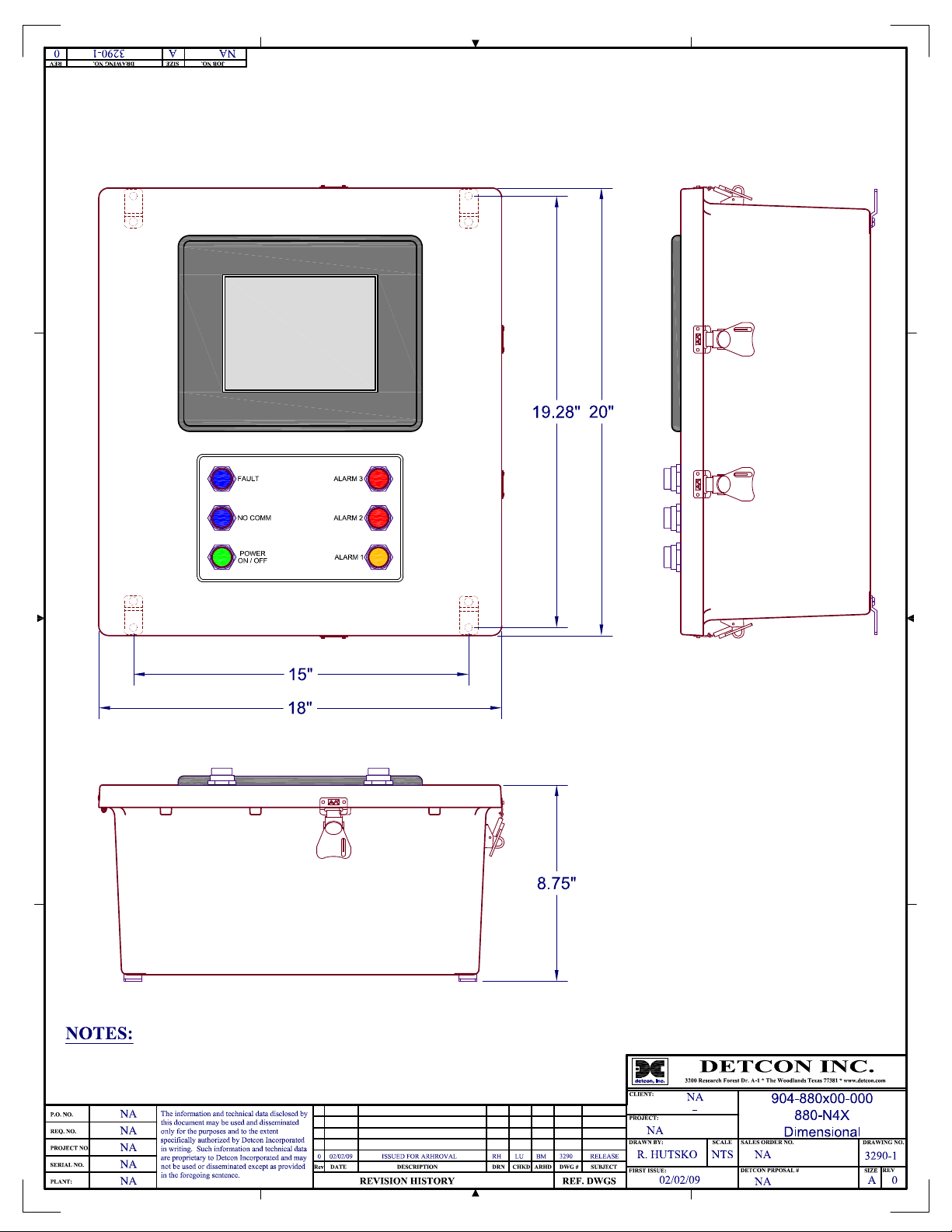
Page 42
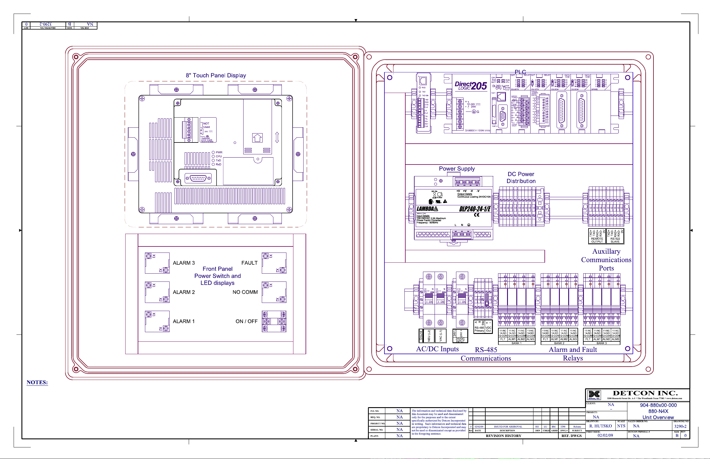
Page 43
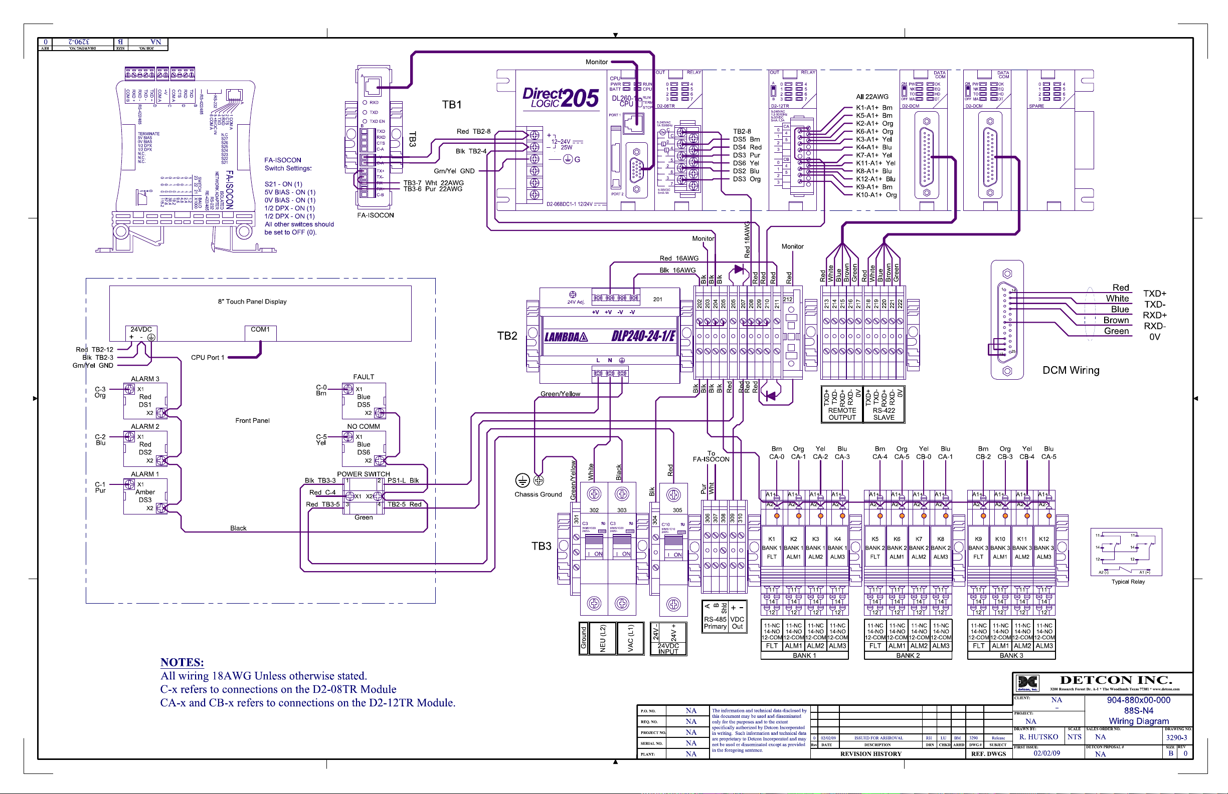
 Loading...