


INSTALLATION AND OPERATING INSTRUCTIONS
VARI-PAK
CYCLING DC MOTOR CONTROL
– Designed for Indexing Applications –
ON STOP OL
VARI-PAK
DC MOTOR SPEED CONTROL
40 |
50 |
60 |
|
||
30 |
|
70 |
20 |
|
80 |
10 |
|
90 |
0 |
% |
100 |
144 S. Wolf Rd
Wheeling, IL 60090
(847) 459-5200
RUN
JOG / STOP
NEMA-12
This manual covers the following CAMCO part numbers: 92A61633010000, 92A61633020000, 92A61633030000, 92A61633040000 92A81359000000
See Safety Warning on Page 2
The information contained in this manual is intended to be accurate. However, the manufacturer retains the right to make changes in design which may not be included herein.
Industrial Motion Control, LLC
© 2003 KB Electronics, Inc.
TABLE OF CONTENTS
Section |
Page |
i. Simplified Operating Instructions . . . . . . . . . . . . . . . . . . . . . . . . . . . . . . . . . . . . . . . . . . . . . 1 ii. Safety Warning . . . . . . . . . . . . . . . . . . . . . . . . . . . . . . . . . . . . . . . . . . . . . . . . . . . . . . . . . . 2 I. Introduction . . . . . . . . . . . . . . . . . . . . . . . . . . . . . . . . . . . . . . . . . . . . . . . . . . . . . . . . . . . . . 2 II. Mounting . . . . . . . . . . . . . . . . . . . . . . . . . . . . . . . . . . . . . . . . . . . . . . . . . . . . . . . . . . . . . . . 8 III. Setting Motor Current (Jumper J1) . . . . . . . . . . . . . . . . . . . . . . . . . . . . . . . . . . . . . . . . . . . 8 IV. Wiring . . . . . . . . . . . . . . . . . . . . . . . . . . . . . . . . . . . . . . . . . . . . . . . . . . . . . . . . . . . . . . . . . 8 V. Fusing . . . . . . . . . . . . . . . . . . . . . . . . . . . . . . . . . . . . . . . . . . . . . . . . . . . . . . . . . . . . . . . 10 VI. Logic Function and Wiring . . . . . . . . . . . . . . . . . . . . . . . . . . . . . . . . . . . . . . . . . . . . . . . . . 10 VII. Application Wiring Diagrams . . . . . . . . . . . . . . . . . . . . . . . . . . . . . . . . . . . . . . . . . . . . . . . 12 VIII. Application Wiring Diagrams (Reversible Models) . . . . . . . . . . . . . . . . . . . . . . . . . . . . . . 15 IX. Operation . . . . . . . . . . . . . . . . . . . . . . . . . . . . . . . . . . . . . . . . . . . . . . . . . . . . . . . . . . . . . . 15 X. Trimpot Adjustments . . . . . . . . . . . . . . . . . . . . . . . . . . . . . . . . . . . . . . . . . . . . . . . . . . . . . 16 XI. Function Indicator Lamps . . . . . . . . . . . . . . . . . . . . . . . . . . . . . . . . . . . . . . . . . . . . . . . . . 17 XII. Troubleshooting Guide . . . . . . . . . . . . . . . . . . . . . . . . . . . . . . . . . . . . . . . . . . . . . . . . . . . 19
Tables
1. Electrical Ratings . . . . . . . . . . . . . . . . . . . . . . . . . . . . . . . . . . . . . . . . . . . . . . . . . . . . . . . . . 3 2. General Performance Specifications . . . . . . . . . . . . . . . . . . . . . . . . . . . . . . . . . . . . . . . . . . 4 3. Selectable Jumper Reference Chart . . . . . . . . . . . . . . . . . . . . . . . . . . . . . . . . . . . . . . . . . . 8 4. Jumper J1 Setting vs Motor Horsepower . . . . . . . . . . . . . . . . . . . . . . . . . . . . . . . . . . . . . . 8 5. Terminal Block Wiring Information . . . . . . . . . . . . . . . . . . . . . . . . . . . . . . . . . . . . . . . . . . . . 9 6. Jumper “JW” Operation . . . . . . . . . . . . . . . . . . . . . . . . . . . . . . . . . . . . . . . . . . . . . . . . . . . 12
Figures
1. Typical Indexing Performance . . . . . . . . . . . . . . . . . . . . . . . . . . . . . . . . . . . . . . . . . . . . . . . 4 2A. Control Layout (Non-Reversing Units) . . . . . . . . . . . . . . . . . . . . . . . . . . . . . . . . . . . . . . . . 5 2B. Control Layout (Reversing Units) . . . . . . . . . . . . . . . . . . . . . . . . . . . . . . . . . . . . . . . . . . . . 6 3. Mechanical Specifications . . . . . . . . . . . . . . . . . . . . . . . . . . . . . . . . . . . . . . . . . . . . . . . . . . 7 4. AC Line & Armature Connection . . . . . . . . . . . . . . . . . . . . . . . . . . . . . . . . . . . . . . . . . . . . . 9 5. Remote Potentiometer Connection . . . . . . . . . . . . . . . . . . . . . . . . . . . . . . . . . . . . . . . . . . 10 6. Analog Voltage Connection . . . . . . . . . . . . . . . . . . . . . . . . . . . . . . . . . . . . . . . . . . . . . . . . 10 7. Run Command . . . . . . . . . . . . . . . . . . . . . . . . . . . . . . . . . . . . . . . . . . . . . . . . . . . . . . . . . 10 8. Jog Command . . . . . . . . . . . . . . . . . . . . . . . . . . . . . . . . . . . . . . . . . . . . . . . . . . . . . . . . . . 11 9. Jog Command used as Stop . . . . . . . . . . . . . . . . . . . . . . . . . . . . . . . . . . . . . . . . . . . . . . . 11 10. Stop Command . . . . . . . . . . . . . . . . . . . . . . . . . . . . . . . . . . . . . . . . . . . . . . . . . . . . . . . . . 11 11. Jumper “JR” Operation . . . . . . . . . . . . . . . . . . . . . . . . . . . . . . . . . . . . . . . . . . . . . . . . . . . 12 12. Solid State Switching . . . . . . . . . . . . . . . . . . . . . . . . . . . . . . . . . . . . . . . . . . . . . . . . . . . . . 13 13. Contact Switching . . . . . . . . . . . . . . . . . . . . . . . . . . . . . . . . . . . . . . . . . . . . . . . . . . . . . . . 13 14. Correct Keyway Position for CAM & Limit Switch Assemblies . . . . . . . . . . . . . . . . . . 13, 14 15. Cycle on Demand Wiring . . . . . . . . . . . . . . . . . . . . . . . . . . . . . . . . . . . . . . . . . . . . . . . . . 14 16. Sequence of Cycle on Demand Operation . . . . . . . . . . . . . . . . . . . . . . . . . . . . . . . . . . . . 15 17. Reversing Logic Wiring Diagram . . . . . . . . . . . . . . . . . . . . . . . . . . . . . . . . . . . . . . . . . . . . 16 18. Internal Wiring Diagram . . . . . . . . . . . . . . . . . . . . . . . . . . . . . . . . . . . . . . . . . . . . . . . . . . . 20
ii

i.SIMPLIFIED OPERATING INSTRUCTIONS
IMPORTANT – You must read these simplified operating instructions before proceeding. These instructions are to be used as a reference only and are not intended to replace the detailed instructions provided herein. You must read the Safety Warning, on page 2, before proceeding.
A.AC Power – Use 120 Volt AC rated controls on 120 Volts AC and 240 Volt AC rated controls on 240 Volts AC. Connect AC power to terminal block TB2 terminals L1 and L2. When power is applied, the power on (ON) LED on the front cover will illuminate.
Be sure input AC line voltage corresponds to control voltage rating. Be sure AC power is disconnected when making other connections to control. Do not bundle AC power and motor wires with wires connected to TB1 terminals.
B.Motor Leads – Connect the motor leads to terminal block TB2 terminals A1 and A2. Be sure motor nameplate voltage rating corresponds to control output voltage rating. Do not use control with shunt wound motors.
A
TB2
A1 |
A2 |
L1 |
L2 |
M |
|
|
|
|
|
|
AC LINE |
MOTOR |
|
INPUT |
|
|
|
||
Earth
 Ground Do not connect
ground wire to any other terminal
JUMPER J1 SETTING vs
MOTOR HORSEPOWER
Jumper J1 |
Motor Horsepower Range |
||||||||||||
|
|
||||||||||||
|
|
|
|
|
|
|
|
|
|
|
|
90 VDC |
180 VDC |
|
|
|
|
|
|
|
|
|
|
|
|
|
|
2A |
|
|
|
|
|
|
|
|
|
|
|
1/6 |
1/3 |
|
|
|
|
|
|
|
|
|
|
|
|||
|
|
|
|
|
|
|
|
|
|
||||
3.3A |
|
|
|
|
|
|
|
|
|
|
|
1/4 – 1/3 |
1/2 – 3/4 |
5A |
|
|
|
|
|
|
|
|
|
|
|||
|
|
|
|
|
|
|
|
|
|
|
1/2 |
1 |
|
10A |
|
|
|
|
|
|
|
|
|
|
|||
|
|
|
|
|
|
|
|
|
|
|
3/4 – 1 |
11⁄2 – 2 |
|
|
|
|
|
|
|
|
|
|
|
|
|
|
|
Note: Jumper “J1” is shown in the factory setting for 120 Volts AC controls (3.3 Amps).
C.Motor Current Setting – Be sure Jumper J1 is set to the approximate rated motor current (10A, 5A, 3.3A, 2A).
D.Trimpot Settings – Trimpots should be set to the approximate position as shown:
|
|
|
MIN |
|
MAX |
|
CL |
|
IR |
||
|
|
|
|
|
|
|
|
|
|
|
|
|
|
|
|
|
|
|
|
|
|
|
|
|
|
|
|
|
|
|
|
|
|
|
|
|
|
|
|
|
|
|
|
|
|
|
|
E.Main Speed Pot – Turn the main speed pot on the front cover of the control to a 15% or greater setting.
Special Instruction for Cycle on Demand Applications
The camshaft of the Index Drive should be in the middle of its dwell position. This is the position in which the motor should receive its signal to start. Connect the normally closed side of the cycling limit switch (LS1) to the control’s TB1 terminals STOP (4) and RTN (3). Note:
See figure 14A-C, on pages 13 and 14, for information regarding the correct dwell position for your Index Drive model and cycling cam lobe positions.
1

ii. |
! SAFETY WARNING! Please read carefully |
This product should be installed and serviced by a qualified technician, electrician, or electrical maintenance person familiar with its operation and the hazards involved. Proper installation, which includes wiring, mounting in proper enclosure, fusing or other over current protection, and grounding can reduce the chance of electrical shocks, fires, or explosion in this product or products used with this product, such as electric motors, switches, coils, solenoids, and/or relays. Eye protection must be worn and insulated adjustment tools must be used when working with control under power. This product is constructed of materials (plastics, metals, carbon, silicon, etc.) which may be a potential hazard. Proper shielding, grounding and filtering of this product can reduce the emission of radio frequency interference (RFI) which may adversely affect sensitive electronic equipment. If further information is required on this product, contact the Sales Department. It is the responsibility of the equipment manufacturer and individual installer to supply this Safety Warning to the ultimate end user of this product. (SW effective 9/2000).
This control contains Start/Stop and Inhibit circuits that can be used to start and stop the control. However, these circuits are never to be used as safety disconnects since they are not fail-safe. Use only the AC line for this purpose.
The potentiometer circuit (P1, P2, P3) of this control is not isolated from AC line. Be sure to follow all instructions carefully. Fire and/or electrocution can result due to improper use of this product.
This product complies with all CE directives pertinent at the time of manufacture. Contact factory for detailed installation and Declaration of Conformity. Installation of a CE approved RFI filter (KBRF-200A [P/N 9945C] or equivalent) is required. Additional shield-
ed motor cable and/or AC line cables may be required along with a signal isolator (Camco P/N 99A61455000000).
A label like the one shown, appears on the top side of your VARI-PAK unit. If this label is not on your control, notify CAMCO immediately! 1-800-645-5207.
I.INTRODUCTION
The VARI–PAK Series is housed in a rugged die cast aluminum NEMA 12 enclosure. The controls are designed specifically for cycling and indexing applications. A variety of models provide different features and input voltage ratings (see table 1, on page 3). The controls provide the user with isolated logic functions: STOP, JOG and RUN. Other functions, such as cycle on demand, can easily be obtained. An important feature of the control is jumper J1 which is used for DC current selection. It automatically presets the IR Compensation and Current Limit for safe operation on various motors. Standard features include an LED indicator array for “power on,” “stop” and “overload.” Part Numbers 92A61633020000 and 92A61633040000 also contain logic input for “Reverse Run” and “Reverse Jog.” The controls contain trimpots that can be used to readjust Minimum and Maximum speed, Current Limit and IR Compensation. The front panel contains a built-in 5K ohm speed potentiometer and a Run, Jog/Stop switch. (See table 3, on page 8, for selectable jumper information.)
2
IMPORTANT! Control part number and ratings must correspond to the AC line voltage, motor voltage and type of operation (Unidirectional or Reversing). See table 1.
TABLE 1 – ELECTRICAL RATINGS
|
Input Line Voltage |
Motor Armature |
Maximum AC |
Maximum DC |
Maximum |
Type of |
|
|
Part Number |
(VAC 50/60 Hz ± |
Load Current |
Load Current |
Horsepower |
Logic Provided |
|||
Voltage (VDC) |
Operation |
|||||||
|
10%) |
(RMS Amps) |
(DC Amps) |
HP, (kW) |
|
|||
|
|
|
|
|||||
|
|
|
|
|
|
|
|
|
92A61633010000 |
120 |
0 – 90 |
15.0 |
10.2 |
1, (0.75) |
Unidirectional |
Run, Jog, Stop, Rtn |
|
92A81359000000 |
||||||||
|
|
|
|
|
|
|
||
|
|
|
|
|
|
|
|
|
|
|
|
|
|
|
|
Fwd Run, Fwd Jog, |
|
92A61633020000 |
120 |
0 – 90 |
15.0 |
10.2 |
1, (0.75) |
Reversing |
Stop, Rev Run, Rev |
|
|
|
|
|
|
|
|
Jog, Rtn |
|
|
|
|
|
|
|
|
|
|
92A61633030000 |
240 |
0 – 180 |
15.0 |
10.2 |
2, (1.5) |
Unidirectional |
Run, Jog, Stop, Rtn |
|
|
|
|
|
|
|
|
|
|
|
|
|
|
|
|
|
Fwd Run, Fwd Jog, |
|
92A61633040000 |
240 |
0 – 180 |
15.0 |
10.2 |
2, (1.5) |
Reversing |
Stop, Rev Run, Rev |
|
|
|
|
|
|
|
|
Jog, Rtn |
|
|
|
|
|
|
|
|
|
3
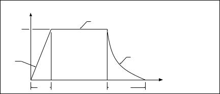
TABLE 2 – GENERAL PERFORMANCE SPECIFICATIONS
|
Specifications |
Specifications |
|||
|
|
|
|
|
|
Parameter |
Part Nos. |
|
Part Nos. |
|
|
|
Factory |
|
Factory |
||
(Units) |
|
|
|||
92A61633010000 |
92A61633030000 |
||||
|
Setting |
Setting |
|||
|
92A61633020000 |
||||
|
|
92A61633040000 |
|
||
|
92A81359000000 |
|
|
||
|
|
|
|
||
|
|
|
|
|
|
AC Line Input |
115 |
— |
208/230 |
— |
|
(VAC ± 10%, 50/60 Hz) |
|||||
|
|
|
|
||
|
|
|
|
|
|
Horsepower Range HP, (kW) |
1/6 – 1, (0.12 – 0.75) |
1/3, (0.25) |
1/3 – 2, (0.25 – 1.5) |
1/4, (0.18) |
|
|
|
|
|
|
|
Armature Voltage Range (VDC) |
0 – 100 |
85 |
0 – 200 |
170 |
|
|
|
|
|
|
|
Current Ranges (ADC) |
2, 3.3, 5, 10 |
3.3 |
2, 3.3, 5, 10 |
2 |
|
|
|
|
|
|
|
CL Trimpot Range |
0 – 170 |
150 |
0 – 170 |
150 |
|
(% Range Setting) |
|||||
|
|
|
|
||
|
|
|
|
|
|
MIN Speed Trimpot Range |
0 – 30 |
0 |
0 – 30 |
0 |
|
(% Base Speed) |
|||||
|
|
|
|
||
|
|
|
|
|
|
MAX Speed Trimpot Range |
60 – 120 |
100 |
60 – 120 |
100 |
|
(% Base Speed) |
|||||
|
|
|
|
||
|
|
|
|
|
|
IR COMP Trimpot Range |
0 – 15 |
4 |
0 – 30 |
8 |
|
(% Base Speed) |
|||||
|
|
|
|
||
|
|
|
|
|
|
Speed Range (Ratio) |
50:1 |
— |
50:1 |
— |
|
|
|
|
|
|
|
AC Line Voltage Regulation |
± 0.5 |
— |
± 0.5 |
— |
|
(% Base Speed) |
|||||
|
|
|
|
||
|
|
|
|
|
|
Voltage Following Linearity |
± 0.5 |
— |
± 0.5 |
— |
|
(% Base Speed) |
|||||
|
|
|
|
||
|
|
|
|
|
|
Load Regulation |
± 1 |
— |
± 1 |
— |
|
(% Base Speed) |
|||||
|
|
|
|
||
|
|
|
|
|
|
Ambient Temperature Range (ºC) |
0 – 45 |
— |
0 – 45 |
— |
|
|
|
|
|
|
|
Potentiometer, Front Cover |
5K – 1/3 |
— |
5K – 1/3 |
— |
|
(ohms – watts) |
|||||
|
|
|
|
||
|
|
|
|
|
|
Maximum Run/Stop Operations |
30 |
— |
30 |
— |
|
(ops/min) |
|||||
|
|
|
|
||
|
|
|
|
|
|
Enclosure Type (NEMA) |
12 |
— |
12 |
— |
|
|
|
|
|
|
|
FIGURE 1 – TYPICAL INDEXING PERFORMANCE
SPEED (rpm)
MOTOR BASE RATED SPEED
1800
|
DECEL WITH |
FIXED |
DYNAMIC BRAKE |
ACCEL |
|
Maximum Cycle Rate: 30 cycles per minute with typical 1 HP motor. Total reflected inertia not to exceed 20% of armature inertia. Acceleration time (fixed at 0.1 sec.) may be extended when operating in Current LImit
100 |
|
TIME (msec) |
|
250 |
|
|
4
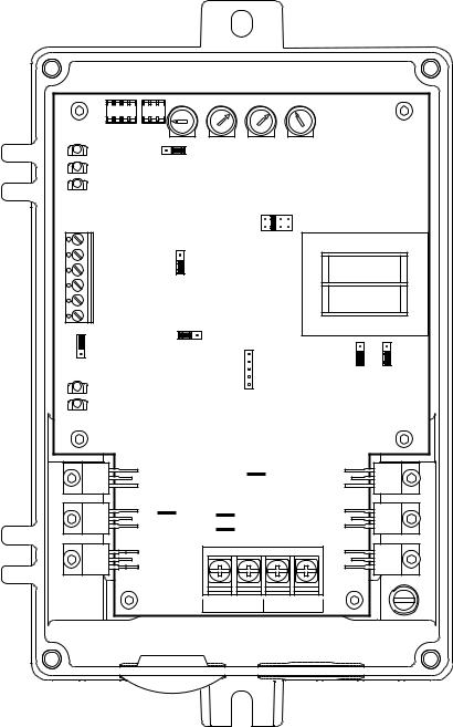
FIGURE 2A – CONTROL LAYOUT (Non-Reversing Units) (92A61633010000, 92A61633030000 and 92A81359000000)
(Illustrates Factory Setting of Jumpers and Approximate Trimpot Settings)
|
|
MIN |
MAX |
|
CL |
IR |
|
|
|
CON1 |
CON2 |
|
|
|
|
|
|
|
P3 |
R |
S |
|
|
|
|
|
|
|
|
|
|
|
|
||
|
P2 |
JW |
|
|
|
|
|
|
|
P1 |
|
|
|
|
|
|
|
|
RUN FWD |
|
|
|
J1 |
2A 3.3A 5A 10A |
|
|
|
(6) |
|
|
|
|
|
||
|
JOG FWD |
|
NO |
|
|
|
|
|
|
(5) |
|
|
|
|
|
|
|
|
STOP |
|
NC |
|
|
KBPI |
|
|
|
(4) |
JS |
|
|
|
|
||
|
RTN |
|
|
|
|
|||
|
(3) |
|
|
|
|
|||
|
|
|
|
|
|
|
|
|
|
+24V |
|
|
|
|
|
|
|
|
(2) |
|
|
|
|
|
|
|
TB1 |
COM |
|
|
|
|
|
|
|
(1) |
90V |
180V |
|
|
|
|
||
|
|
|
|
|
||||
|
|
|
|
|
|
|||
|
F |
|
|
J3 |
|
|
|
|
|
JR |
|
|
|
|
|
240V |
|
|
O |
|
|
|
|
|
120V |
|
|
|
|
|
|
|
|
||
|
RB1 |
|
|
|
|
|
J2B |
J2A |
|
|
|
|
P4 |
|
|
|
|
|
|
|
|
|
|
|
|
|
|
RB2 |
|
|
|
|
|
|
|
|
|
|
|
|
A1A |
|
|
|
|
|
A2A |
|
|
|
|
|
|
|
|
|
A1B |
|
A2B |
|
|
|
|
|
|
TB2 |
|
|
|
|
|
|
|
|
|
A1 |
A2 |
L1 |
L2 |
|
5

FIGURE 2B – CONTROL LAYOUT (Reversing Units) (92A61633020000 and 92A61633040000)
(Illustrates Factory Setting of Jumpers and Approximate Trimpot Settings)
MIN |
MAX |
CL |
IR |
CON1 CON2
|
P3 |
|
|
P2 |
|
|
P1 |
|
|
RUN REV |
|
|
(8) |
|
|
JOG REV |
|
|
(7) |
|
|
RUN FWD |
|
|
(6) |
|
|
JOG FWD |
|
|
(5) |
|
|
STOP |
|
|
(4) |
|
|
RTN |
|
|
(3) |
|
|
+24V |
|
|
(2) |
|
TB1 |
COM |
|
(1) |
||
|
||
JR |
F |
|
|
O |
|
|
RB1 |
|
|
RB2 |
R |
S |
JW
|
|
|
|
|
|
|
J1 |
|
|
|
|
|
|
|
|
|
|
|
|
|
|
|
|
|
|
|
|
|
|
|
|
|
|
|
|
|
|
|
|
|
|
|
|
|
|
|
|
|
|
2A 3.3A 5A 10A |
|
||||
|
|
|
NO |
|
|
|
|
|
|
||||
|
|
|
|
|
|
|
|
|
|||||
|
|
|
NC |
|
|
|
KBPI |
|
|||||
|
|
|
|
||||||||||
|
|
JS |
|
||||||||||
|
90V 180V |
|
|
|
|
|
|
||||||
|
|
|
|
|
|
|
|||||||
|
|
|
|
|
|
|
|||||||
|
|
|
|
|
|
|
|||||||
|
|
|
|
|
|
|
|||||||
|
|
|
|
|
|
J3 |
|
|
|
|
|
|
|
|
|
|
|
|
|
|
|
|
|
|
|
|
|
|
|
|
|
|
|
|
|
P1 |
|
||||
KBPI RELAY
|
|
|
|
|
|
|
A1A |
||||||
|
|
|
|
|
|
|
|
|
|
|
|
120V |
|
|
|
|
|
|
|
|
|
|
|
|
|
||
A2A |
|
A1B |
|
A2B |
|
|
|
|
|||||
|
|
|
|
|
|
J1 |
|
240V |
|||||
|
|
|
|
|
|
|
|
|
|||||
|
|
|
|
|
|
|
|
|
|
|
|
||
|
|
|
|
|
|
|
|
|
|
|
|
||
TB2
240V
 120V
120V 
J2B J2A
|
|
|
|
|
|
|
|
|
|
|
|
|
|
|
|
|
|
|
|
|
|
|
|
|
|
|
|
|
|
|
|
|
|
|
|
|
|
|
|
|
|
|
|
|
|
|
|
|
|
|
|
|
|
|
|
|
|
|
|
|
|
|
|
|
|
|
|
|
|
|
|
|
|
|
|
|
|
|
|
|
|
|
|
|
|
|
|
|
|
|
|
|
|
|
|
|
|
|
|
|
|
|
|
|
|
|
|
|
|
|
|
|
|
|
|
|
|
|
|
|
|
|
|
|
|
|
|
|
|
|
|
|
|
|
|
|
|
|
|
|
|
|
|
|
|
|
|
|
|
|
|
|
|
|
|
|
|
|
|
|
|
|
|
|
|
|
|
|
|
|
|
|
|
|
|
|
|
|
|
|
|
|
|
|
|
|
|
|
|
|
|
|
|
|
|
|
|
|
|
|
|
|
|
|
|
|
|
|
|
|
|
|
|
|
|
|
|
|
|
|
|
|
|
|
|
|
|
|
|
|
|
|
|
|
|
|
|
|
|
|
|
|
|
|
|
|
|
|
|
|
A1 |
|
A2 |
|
|
L1 |
|
|
L2 |
|
|
|
|
|
|
|
|
|
|
|
|
|
|
|
||||||||||||||||||||
|
|
|
|
|
|
|
|
|
|
|
|
|
|
|
|
|
|
|
|
|
|
|
|
|
|
|
|
|
|
|
|
|
|
|
||||||||||||||||||||||||
|
|
|
|
|
|
|
|
|
|
|
|
|
|
|
|
|
|
|
|
|
|
|
|
|
|
|
|
|
|
|
|
|
|
|
|
|
|
|
|
|
|
|
|
|
|
|
|
|
|
|
|
|
|
|
|
|
|
|
|
|
|
|
|
|
|
|
|
|
|
|
|
|
|
|
|
|
|
|
|
|
|
|
|
|
|
|
|
|
|
|
|
|
|
|
|
|
|
|
|
|
|
|
|
|
|
|
|
|
|
|
|
|
|
|
|
|
|
|
|
|
|
|
|
|
|
|
|
|
|
|
|
|
|
|
|
|
|
|
|
|
|
|
|
|
|
|
|
|
|
|
|
|
|
|
|
|
|
|
|
|
|
|
|
|
|
|
|
|
|
|
|
|
|
|
|
|
|
|
|
|
|
|
|
|
|
|
|
|
|
|
|
|
|
|
|
|
|
|
|
|
|
|
|
|
|
|
|
|
|
|
|
|
|
|
|
|
|
|
|
|
|
|
|
|
|
|
|
|
|
|
|
|
|
|
|
|
|
|
|
|
|
|
|
|
|
|
|
|
|
|
|
|
|
|
|
|
|
|
|
|
|
|
|
|
|
|
|
|
|
|
|
|
|
|
|
|
|
|
|
|
|
|
|
|
|
|
|
|
|
|
|
|
|
|
|
|
|
|
|
|
|
|
|
|
|
|
|
|
|
|
|
|
|
|
|
|
|
|
|
|
|
|
|
|
|
|
|
|
|
|
|
|
|
|
|
|
|
|
|
|
|
|
|
|
|
|
|
|
|
|
|
|
|
|
|
|
|
|
|
|
|
|
|
|
|
|
|
|
|
|
|
|
|
|
|
|
|
|
|
|
|
|
|
|
|
|
|
|
|
|
|
|
|
|
|
|
|
|
|
|
|
|
|
|
|
|
|
|
|
|
|
|
6
 Loading...