

Page 1

Getting Started Guide
IM-pAC
AC variable speed drive for
3 phase induction motors
from 0.25kW to 4kW,
0.33hp to 5hp
Model sizes A, B and C
Part Number: 0472-0056-05
Issue: 5
Page 2

General Information
The manufacturer accepts no liability for any consequences resulting from inappropriate, negligent
or incorrect installation or adjustment of the optional parameters of the equipment or from
mismatching the variable speed drive with the motor.
The contents of this guide are believed to be correct at the time of printing. In the interests of
commitment to a policy of continuous development and improvement, the manufacturer reserves the
right to change the specification of the product or its performance, or the content of the guide without
notice.
All rights reserved. No parts of this guide may be reproduced or transmitted in any form or by any
means, electrical or mechanical including, photocopying, recording or by an information storage or
retrieval system, without permission in writing from the publisher.
Copyright © August 2008 IMC
Issue: 5
Page 3

Contents
1 Read Me First Instructions ..... ... .... ... ... ... ... .... ... ... ... ....... ... ..6
1.1 Data Sheet ..............................................................................................6
1.2 Drive Size ................................................................................................ 6
1.3 Safety ......................................................................................................6
1.4 Mounting of Drive ....................................................................................6
1.5 Wiring Motor ............................................................................................ 6
1.6 Motor Jumper Configuration for 1/3 hp and 1.00 hp motors ...................7
1.7 Wiring Power and Switches to Drive .......................................................7
1.8 Programming ...........................................................................................8
1.9 Speed Control .........................................................................................8
1.10 Overload Protection .................................................................................9
1.11 Brake Motors ...........................................................................................9
1.12 Reversing the Motor ................................................................................ 9
1.13 Emergency Stop Safety ...........................................................................9
1.14 Warranty and Return Policy ....................................................................9
1.15 Disposal ...................................................................................................9
1.16 Indexer drive shown in middle of dwell position diagram. .......................9
1.17 Drive default parameter list for a single preset speed application .........10
1.18 Drive parameter list for using a potentiometer to control speed ............12
1.19 Drive parameter list for using a potentiometer to control speed with a
1.20 Drive parameter list for using a potentiometer and switch selected
1.21 Drive wiring for using a potentiometer and switch selected presets to
1.22 Drive parameter list for using a PLC to control speed ...........................20
1.23 Drive wiring for a PLC to control speed .................................................21
1.24 How to configure the IM-pAC drive to trip for a current overload. .........22
1.25 Drive parameter list for a motor reversing application ...........................24
1.26 Drive wiring for a motor reversing application. ......................................27
1.27 Drive parameter list for a 24Vdc brake motor ........................................28
1.28 Drive wiring for a 24Vdc brake motor .................................................... 30
1.29 Drive and Options part numbers ...........................................................31
2 Safety Information ................ .............................................32
2.1 Warnings, Cautions and Notes .............................................................. 32
2.2 Electrical Safety - general warning ........................................................32
2.3 System design and safety of personnel ................................................32
2.4 Environmental Limits ............................................................................. 32
2.5 Access ...................................................................................................33
2.6 Compliance and regulations ..................................................................33
2.7 Motor .....................................................................................................33
2.8 Adjusting parameters ............................................................................33
2.9 Electrical installation ..............................................................................33
proximity switch for cycling ....................................................................14
presets to control speed ........................................................................17
control speed .........................................................................................19
IM-pAC Getting Started Guide 3
Issue Number: 5 www.camcoindex.com | www.destaco.com
Page 4

3 Rating Data ........... ... ... ... ....................................................35
4 Mechanical Installation .............................. ....................... 37
5 Electrical Installation . ... .... ................................................39
5.1 Power terminal connections ..................................................................39
5.2 Ground leakage .....................................................................................40
5.3 EMC ......................................................................................................41
5.4 Control terminals I/O specification .........................................................42
6 Keypad and Display ..........................................................46
6.1 Programming keys ................................................................................46
6.2 Control keys ..........................................................................................46
6.3 Selecting and changing parameters ......................................................47
6.4 Saving parameters ................................................................................48
6.5 Parameter access .................................................................................48
6.6 Security codes .......................................................................................48
7 Parameters ............... ... ... .... ... ... ... .... ...................................50
7.1 Parameter descriptions - Level 1 ...........................................................50
7.2 Parameter descriptions - Level 2 ...........................................................57
7.3 Parameter descriptions - Level 3 ...........................................................66
7.4 Diagnostic parameters ..........................................................................66
8 Diagnostics .............................. ... .... ... ... ... ... .... ...................67
9 UL Listing Information ......................................................70
9.1 Common UL information (for IM-pAC size A and B) .............................70
9.2 Power dependant UL information ..........................................................70
4 IM-pAC Getting Started Guide
www.camcoindex.com | www.destaco.com Issue Number: 5
Page 5

Declaration of Conformity
IMC
92C85797010000
92C85797020000
92B9048
92B90482020000
92B90482030000
92B90482040000
92B90482050000
92B90482060000
92B90482070000
92B90482080000
92B90482090000
The AC variable speed drive products listed above have been designed and
manufactured in accordance with the following European harmonised standards:
2010000
EN 61800-5-1
EN 61800-3
EN 61000-6-2
EN 61000-6-4
EN 61000-3-2
EN 61000-3-3
These products comply with the Low Voltage Directive 73/23/EEC, the Electromagnetic
Compatibility (EMC) Directive 89/336/EEC and the CE Marking Directive 93/68/EEC.
These electronic drive products are intended to be used with appropriate motors,
controllers, electrical protection components and other equipment to form
complete end products or systems. Compliance with safety and EMC regulations
depends upon installing and configuring drives correctly, including using the
specified input filters. The drives must be installed only by professional
assemblers who are familiar with requirements for safety and EMC. The
assembler is responsible for ensuring that the end product or system complies
with all the relevant laws in the country where it is to be used. Refer to the IM-pAC
Getting Started Guide. An EMC Data Sheet is also available giving detailed EMC
information.
Adjustable speed electrical power drive systems - safety requirements
- electrical, thermal and energy
Adjustable speed electrical power drive systems. EMC product
standard including specific test methods
Electromagnetic compatibility (EMC). Generic standards. Immunity
standard for industrial environments
Electromagnetic compatibility (EMC). Generic standards. Emission
standard for industrial environments
Electromagnetic compatibility (EMC), Limits, Limits for harmonic
current emissions (equipment input current <16A per phase)
Electromagnetic compatibility (EMC), Limits, Limitation of voltage
fluctuations and flicker in low-voltage supply systems for equipment
with rated current <16A
IM-pAC Getting Started Guide 5
Issue Number: 5 www.camcoindex.com | www.destaco.com
Page 6

1 Read Me First Instructions
1.1 Data Sheet
You will need a copy of the data sheet your sales representative provided you for your
application. You will need to refer to the data sheet in order to set motor speeds and
dwell times.
1.2 Drive Size
You will need to determine which size drive you have for proper mounting and wiring.
IMC Part Number
92C85797010000 A 1 HP 0.75 kW 200 - 240V 0.75 kW single phase 48-62 hz IM-pAC Blue
92C85797020000 B 1 HP 0.75 kW 380 - 460V 0.75 kW three phase 48-62 hz IM-pAC Blue
2010000 B 1.5 HP 1.1 kW 200 - 240V 1.1 kW single
92B9048
92B90482020000 B 2 HP
2030000 C 3 HP
92B9048
92B904820400
92B90482050000 C 3 HP
92B904820600
92B904820700
92B904820800
92B904820900
Drive
Motor Power Rating Drive Color
size
phase 48-62 hz SK Green
1.5 kW 200 - 240V 1.5 kW single phase 48-62 hz SK Green
2.2 kW 200 - 240V 2.2 kW single phase 48-62 hz SK Green
00 B 2 HP 1.5 kW 380 - 460V 1.5 kW three phase 48-62 hz SK Green
2.2 kW 380 - 460V 2.2 kW three phase 48-62 hz SK Green
00 C 5 HP
00 B 1 HP 0.75 kW 1
00 B 1.5 HP 1.1
00 B 1.5 HP 1.1
4.0 kW 380 - 460V 4.0 kW three phase 48-62 hz SK Green
00-120V 0.75 kW single phase 48-62 hz SK Green
kW 100-120V 1.1 kW single phase 48-62 hz SK Green
kW 380 - 460V 1.1 kW three phase 48-62 hz SK Green
NOTE
Single phase can be obtained from a 3 phase "wye" by wiring two of the "hots" (L1 and
L2 or L2 and L3 or L1 and L3) to the single phase control. Power supplied to the drive
must be from a balanced power supply with an earth ground. A floating ground or an
unbalanced supply can permanently damage the drive.
1.3 Safety
Read Chapter 2 Safety Information before mounting or wiring the drive.
The STOP and START controls or electrical inputs of the drive must not be relied upon
to ensure the safety of the personnel. They do not isolate dangerous voltages from the
output of the drive or from any external unit. The supply must be disconnected by an
approved electrical isolation device before gaining access to electrical connections. The
drive contains capacitors that remain charged to a potentially lethal voltage after AC
supply has been disconnected. Wait at least 10 minutes for the stored charge to
dissipate. See section 2.9.4 Stored charge .
1.4 Mounting of Drive
The drive is designed to mount to a wall within a control panel or on a DIN rail. For
proper functioning, mount the drive with the minimum recommended clearances. See
Chapter 4.
1.5 Wiring Motor
The IMC high performance motor can be wired as either 200 or 400 volts. Wire the
motor as 200V for the A Size IM-pAC and wire the motor as 400V for the B Size IMpAC. See section 5.1, Figure 5-1 and Figure 5-2.
6 IM-pAC Getting Started Guide
www.camcoindex.com | www.destaco.com Issue Number: 5
Page 7
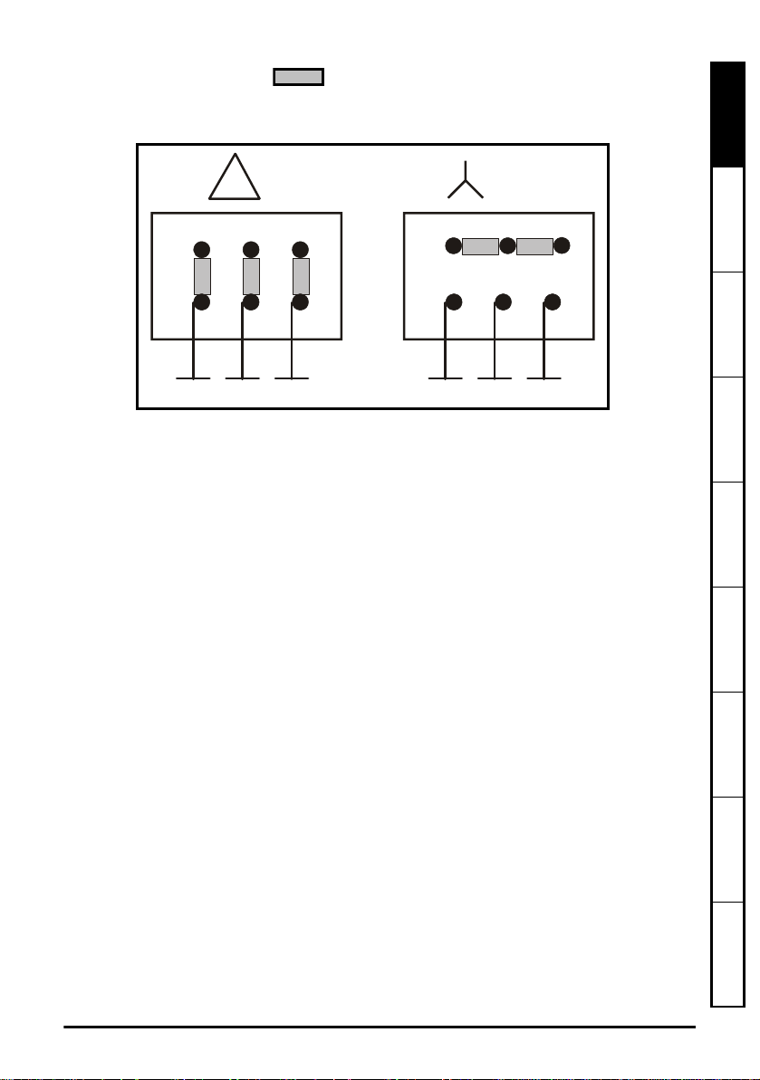
1.6 Motor Jumper Configuration for 1/3 hp and 1.00 hp
W2 U2 V2
U1 V1 W1
230V
W2 U2 V2
U1 V1 W1
400-460V
L1
L2 L3
L1
L2 L3
motors
1.7 Wiring Power and Switches to Drive
1. Refer to Chapter 3 Rating Datafor all other fuse sizes and control and motor cable
wire sizes. Single phase can be obtained from a 3 phase "wye" by wiring two of the
"hots" (L1 and L2 or L2 and L3 or L1 and L3) to the drive. Do not remove internal
EMC filter. See Chapter 5.
2. The control terminal B2 outputs 24 volts DC and will be used to power the signals.
The control terminal B4 is used to enable the drive. As long as B2 and B4 are
connected the drive will run. Use a normally closed switch (not supplied by IMC) or
jumper between B2 and B4 to enable the drive. The control terminal B5 runs the
motor forward and B6 runs the motor in reverse. If the indexer is not turning in the
proper direction interchange B5 and B6.
Read Me First
Instructions
Safety Information Rating Data
Mechanical
Installation
Electrical Installation Keypad and Display Parameters Diagnostics
3. Make sure the indexer is in the middle of its dwell position before starting or
stopping the motor. see section 1.16 Indexer drive shown in middle of dwell
position diagram. on page 9.
4. The motor is made to run by closing the B2-B5 or B2-B6 terminals. Opening them
will stop the motor.
5. Cycling on demand using a limit switch and inverter duty motor. The normally closed
side of the cam shaft limit switch should be wired to terminals B2 and B5 (or B6).
When the indexer is in dwell the switch will be open. A start signal is sent by
momentarily closing B2 and B5 with an external switch. As the camshaft is turning
the limit switch on the cam shaft will close and thus maintain the B2-B5 (or B6)
closure. When the indexer enters dwell the trip cam on the cam shaft will cause the
IM-pAC Getting Started Guide 7
Issue Number: 5 www.camcoindex.com | www.destaco.com
limit switch to open the B2-B5 (or B6) connection and stop the motor.
Diagram for wiring switches to the IM-pAC control terminals (cover has been removed)
for cycling on demand using a limit switch, momentary start and inverter duty motor.
Index drive is in middle of dwell position see section 1.16 Indexer drive shown in middle
of dwell position diagram. on page 9.
Information
UL Listing
Page 8
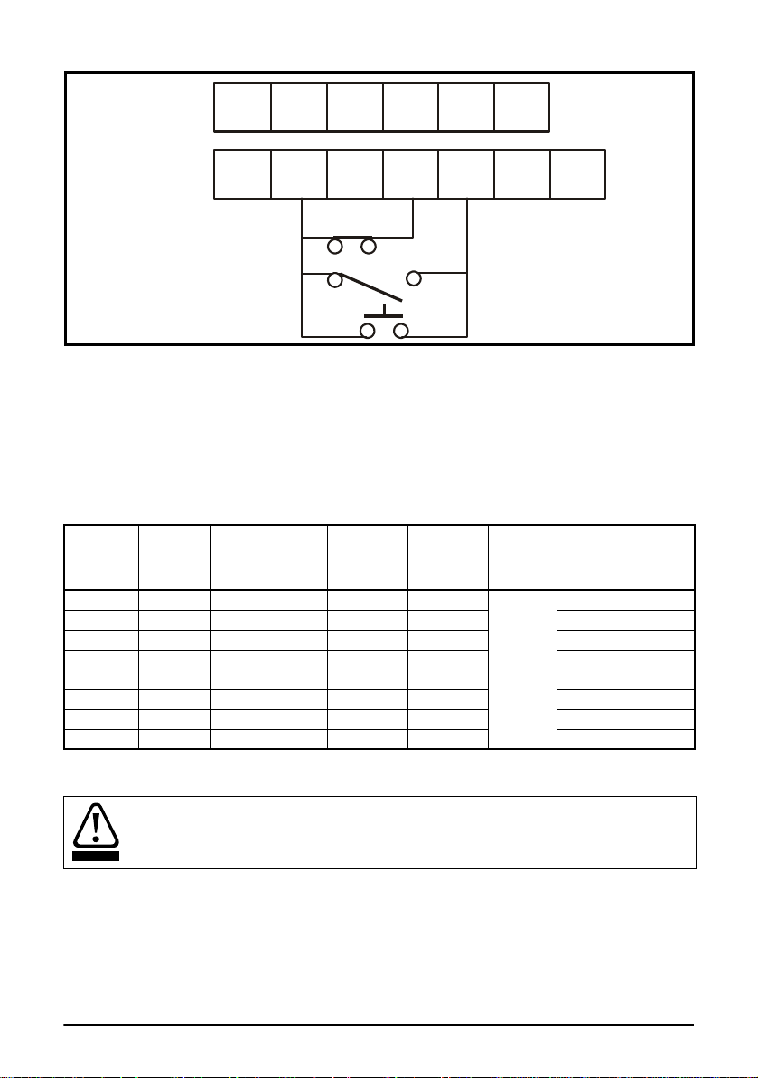
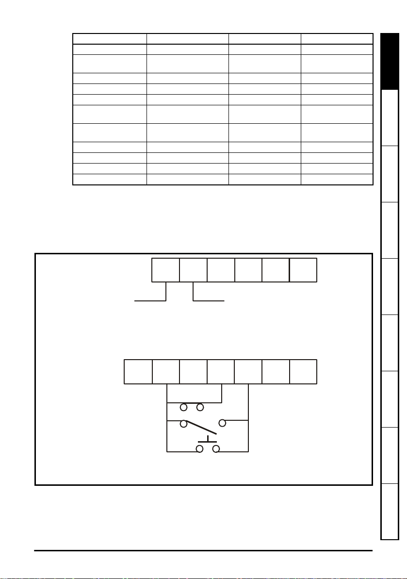
1.8 Programming
T1 T2 T3 T4 T5 T6
B1 B2 B3 B4 B5 B6 B7
Drive enabled (normally closed)
Stop signal switch on camshaft
(normally closed)
Momentary Start
Radio Shack Pt.No 275-324
IMC Pt.No 87C08062019510
Radio Shack Pt.No 275-609
WARNING
The IM-pAC drive is delivered to you programmed for the 1/3 hp 230V 60 hz motor (IMC
Pt. No 92C49952070000). For a different motor rated frequency, amperage, voltage or
power factor you must change the motor parameters Pr 39, Pr 06, Pr 08 and Pr 09.
Below is a chart of the values for all the possible configurations of the standard IMC
motors. If you are not using an IMC motor then you must read these values from the
motor name plate. See section 6.3 Selecting and changing parameters on page 47 for
how to edit the parameter values.
hp kw IMC Motor
0.33 0.25 92C49952070000 60 1.14
0.33 0.25 92C49952070000 60 0.57 460 0.74
0.33 0.25 92C49952070000 50 1.14 200 0.74
0.33 0.25 92C49952070000 50 0.57 400 0.74
1.00 0.75 92C49955410000 60 3.15 230 0.79
1.00 0.75 92C49955410000 60 1.9 460 0.66
1.00 0.75 92C49955410000 50 3.65 200 0.70
1.00 0.75 92C49955410000 50 2.1 400 0.70
1.9 Speed Control
Never auto tune the motor
You must now determine how you wish to control the maximum speed for your
application.
You can use a single preset speed parameter, or use an external potentiometer, or use
a potentiometer and 3 other preset speeds, or use a PLC to control speed. Please refer
to one of the four parameter list sections for the additional parameter changes for the
speed control you require for your application.
8 IM-pAC Getting Started Guide
Power
Frequency
Pr 39
hz
Current
Pr 06
amp
Rpm
Pr 07
0
Voltage
Pr 08
volt
230 0.74
factor
Pr 09
cos
∅
www.camcoindex.com | www.destaco.com Issue Number: 5
Page 9
1.10 Overload Protection
NOTE
The IM-pAC drive can provide protection to the indexer if the indexer is restrained from
movement by an obstruction or jammed during motion. See section 1.24 How to
configure the IM-pAC drive to trip for a current overload. on page 22
Read Me First
Instructions
1.11 Brake Motors
See "24V brake motor - wiring and parameters" section.
1.12 Reversing the Motor
See "Reversing the motor direction - wiring and parameters" section.
1.13 Emergency Stop Safety
It is recommended that you purchase a commercial safety relay and motor contactor
product from a vendor such as Schneider Electric, Square D, Telemecanique or Phoenix
Contact that complies with the OSHA, ANSI or IEC safety directives you are required to
follow.
The drive must be disabled (open the B2 - B4 connection) before the motor contactors
are opened. Failure to do so will damage the drive.
1.14 Warranty and Return Policy
The IM-pAC Drive is warranted for 1 year from date of receipt. For technical support call
CAMCO-FERGUSON (847-215-5658).
1.15 Disposal
Waste Electrical and Electronic Equipment (WEEE) Directive and the Restriction on the
use of Hazardous Waste (RoHS) Directive does not apply to the IM-pAC drive.
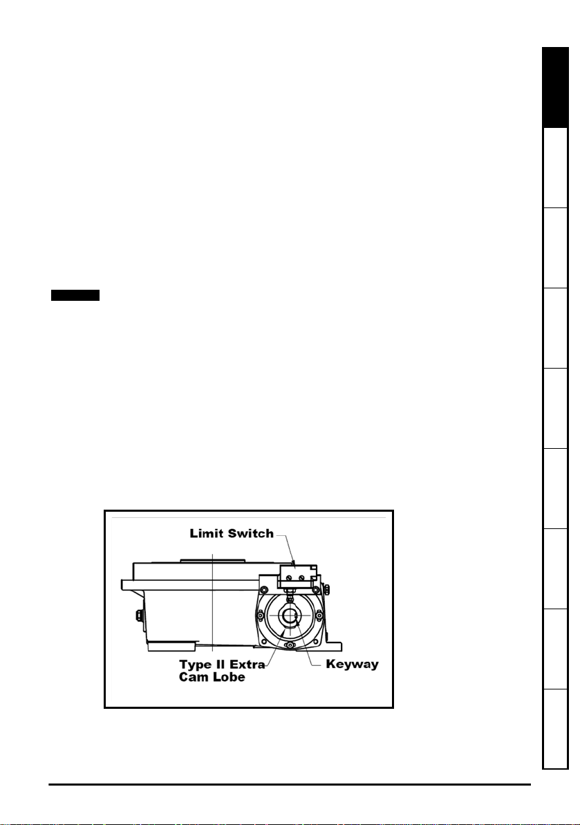
1.16 Indexer drive shown in middle of dwell position diagram.
Camshaft keyway position of a Roller Gear, Right Angle or Parallel indexer stopped in
the middle of dwell. For an RPP, LPP or WBD see the timing diagram or an assembly
drawing for the middle dwell locations.
Safety Information Rating Data
Mechanical
Installation
Electrical Installation Keypad and Display Parameters Diagnostics
A standard Roller Gear unit with cam and limit or proximity switch mounted on the correct
keyway position directly opposite of the output shaft, 90 degrees clockwise from the cam
lobe. The cam and switch may also be mounted on the reducer. If the unit is a Type II
motion a special switch cam is need with one extra lobe, 180 degrees from the first lobe.
IM-pAC Getting Started Guide 9
Issue Number: 5 www.camcoindex.com | www.destaco.com
Information
UL Listing
Page 10
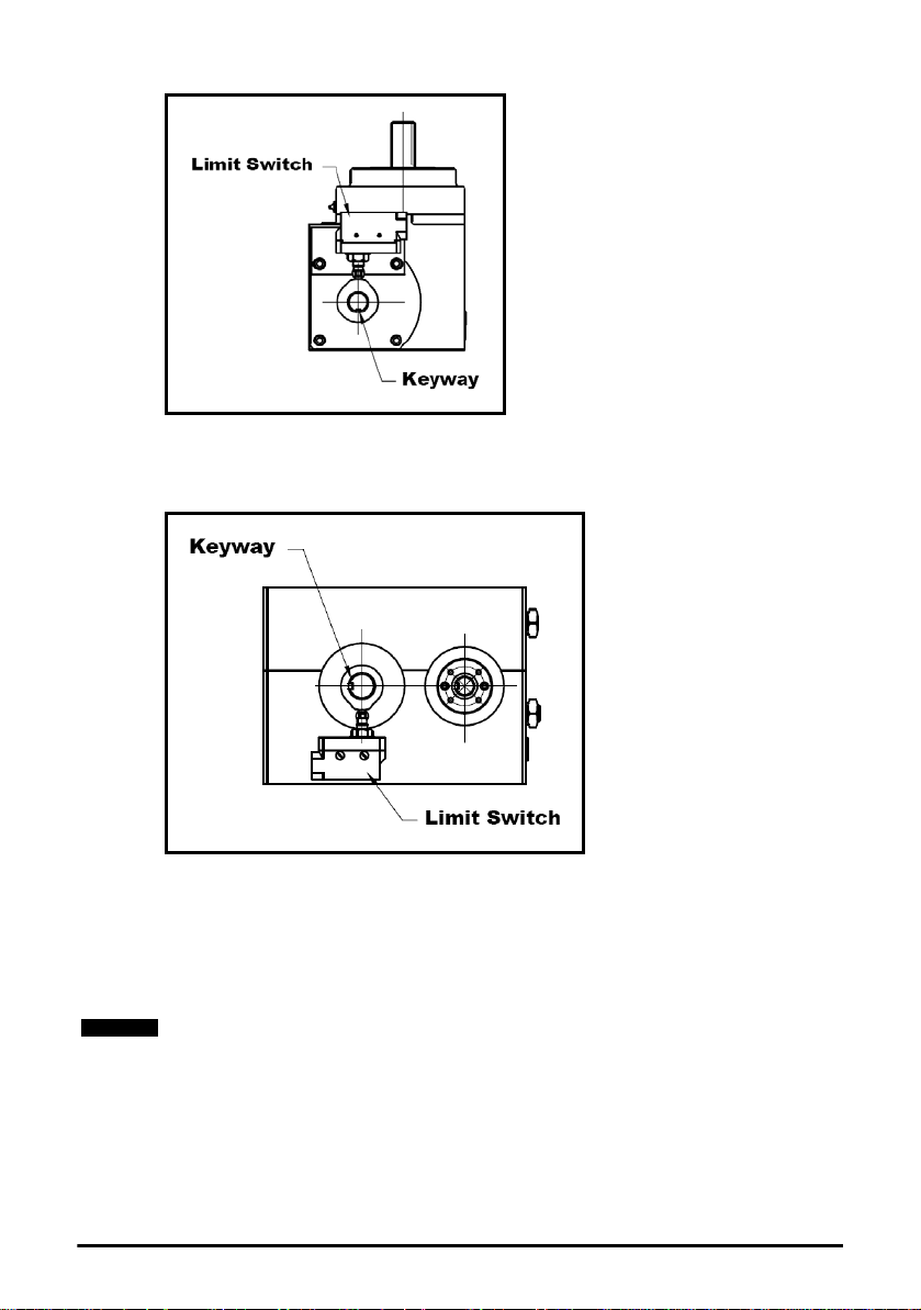
A standard Right Angle unit with cam and limit or proximity switch mounted on the
NOTE
housing has a correct keyway position directly opposite the cam lobe. The cam and
switch may also be mounted on the reducer.
A standard Parallel unit with cam and limit or proximity switch mounted on the housing
has a correct keyway position directly opposite the output shaft, 90 degrees clockwise
from the cam lobe. The cam and switch may also be mounted on the reducer.
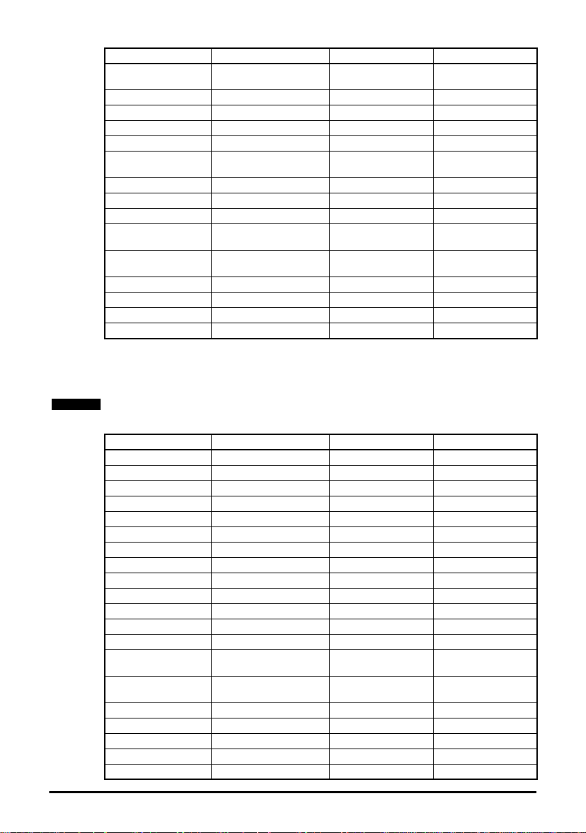
1.17 Drive default parameter list for a single preset speed application
a) Default parameters are for motor 92C49952070000 1/3 hp. 230 V 60 hz motor. See
motor name plate.
10 IM-pAC Getting Started Guide
www.camcoindex.com | www.destaco.com Issue Number: 5
Page 11

b) You should have a copy of the data sheet for the indexer application in order to set
NOTE
Pr 18 correctly. You must change Pr 10 (Security Level) to 2 or L3 before you can change
Pr 18, the preset speed. On the data sheet you will find the motor speed for your
application and the motor's rated rpm.
Use the following calculation to determine Pr 18.
Pr 18 = Pr 39 x Motor Speed for Application / Motor Rated RPM
Pr 18 = 60 hz x 1650 rpm / 1750 rpm = 57 hz (round all values up to a whole number)
Parameter Description Value Units
Pr 01 Minimum set speed 0 Hz
Pr 02 Maximum set speed 60 Hz
Pr 03 Acceleration rate 1 0.1 s/100Hz
Pr 04 Deceleration rate 1 0.2 s/100Hz
Pr 05 Drive configuration 3:Pr
Pr 06 Motor rated current 1.14 A (from motor plate)
Pr 07 Motor rated full load rpm 0 RPM (always 0)
Pr 08 Motor rated voltage 230 V (from motor plate)
Pr 09 Motor rated power factor 0.74 (from motor plate)
Pr 10 Security status 2:L3
Pr 11 Start / stop logic select 0
Pr 12 Brake controller enable 0:dis
Pr 15 Jog reference 1.5 Hz
Pr 16
Pr 17
Pr 18 Preset speed 1 57 Hz (See note b)
Pr 19 Preset speed 2 0 Hz
Pr 20 Preset speed 3 0 Hz
Pr 21 Preset speed 4 0 Hz
Pr 22 Load display units Ld
Pr 23 Speed display units 0:Fr
Pr 24 Customer defined scaling 1
Pr 25 User security code 0
Pr 27
Pr 28 Parameter cloning 0:no
Pr 29 Load defaults 0:no
Pr 30 Ramp mode select 3:FSt.Hv
Pr 31 Stopping mode select 1
Pr 32 Dynamic V to f select OFF
Pr 33
Pr 34 Terminal B7 mode select 0:dig
Pr 35
Pr 36
Analog input 1 mode
(terminal T2)
Allow negative
references
Power-up keypad
reference
Catch a spinning motor
select
Digital output control
(terminal B3)
Analog output control
(terminal Bi)
6:VoLt
OFF
0
0
0:n=0
0:Fr
Read Me First
Instructions
Safety Information Rating Data
Mechanical
Installation
Electrical Installation Keypad and Display Parameters Diagnostics
Information
UL Listing
IM-pAC Getting Started Guide 11
Issue Number: 5 www.camcoindex.com | www.destaco.com
Page 12
Parameter Description Value Units
NOTE
Pr 37
Pr 38 Auto-tune 0
Pr 39 Motor rated frequency 60 Hz (from motor plate)
Pr 40 Number of motor poles 2:4 pole
Pr 41 Voltage mode select 2:Fd
Pr 42
Pr 43 Serial comms baud rate 19.2
Pr 44 Serial comms address 1
Pr 45 Software version 1.04
Pr 46
Pr 47
Pr 48 Brake release frequency 1 Hz
Pr 49 Brake apply frequency 2 Hz
Pr 50 Pre-brake release delay 0 s
Pr 51 Post brake release delay 0 s
Maximum switching
frequency
Low frequency voltage
boost
Brake release current
threshold
Brake apply current
threshold
12 kHz
4
50
10
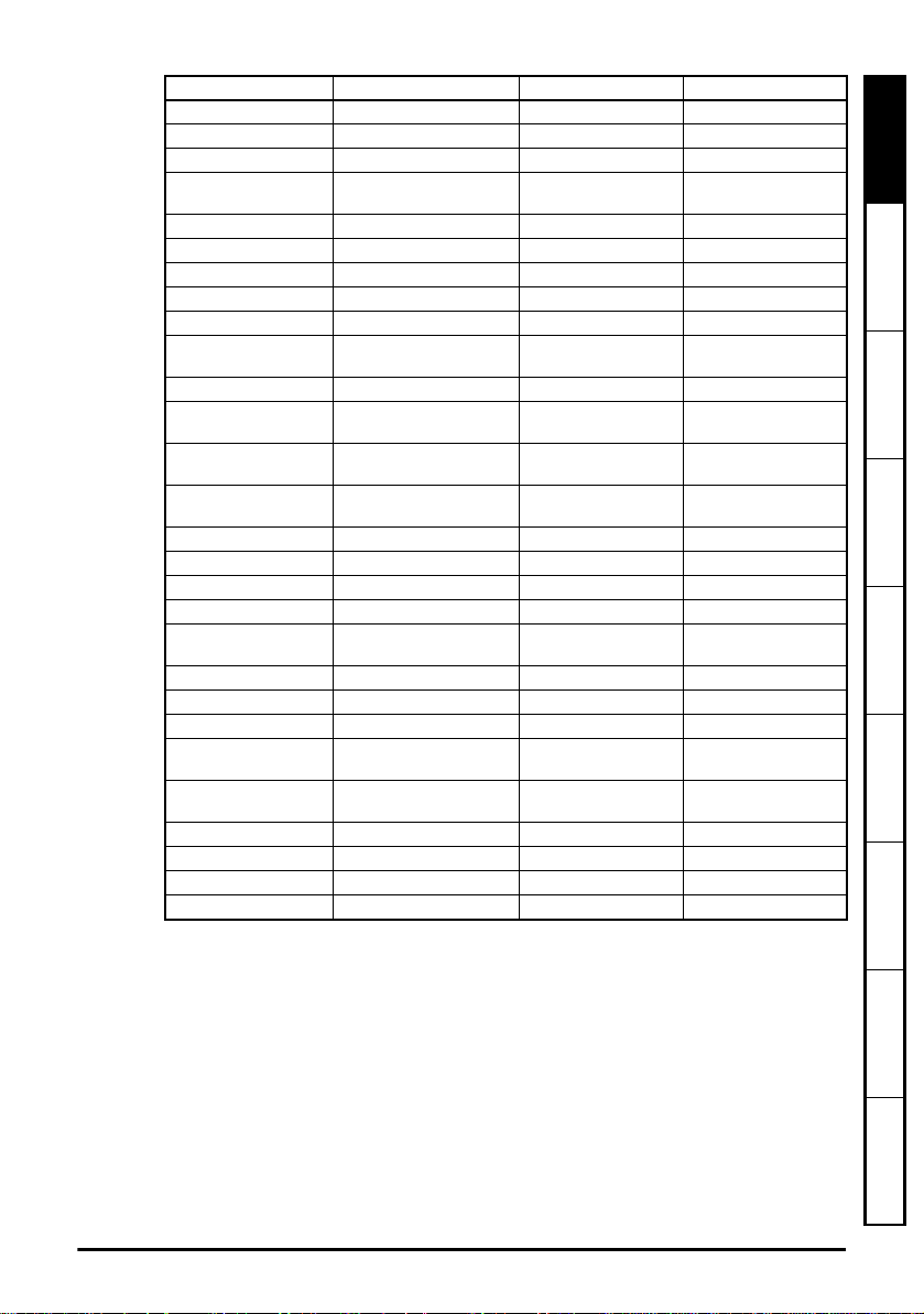
1.18 Drive parameter list for using a potentiometer to control speed
The speed range of the potentiometer is from 0 to the Pr 02 value.
Parameter Description Value Units
Pr 01 Minimum set speed 0 Hz
Pr 02 Maximum set speed 60 Hz
Pr 03 Acceleration rate 1 0.1 s/100Hz
Pr 04 Deceleration rate 1 0.2 s/100Hz
Pr 05 Drive configuration 1:Av.Pr
Pr 06 Motor rated current - A (from motor plate)
Pr 07 Motor rated full load rpm 0 RPM (always 0)
Pr 08 Motor rated voltage - V (from motor plate)
Pr 09 Motor rated power factor - (from motor plate)
Pr 10 Security status 0:L1
Pr 11 Start / stop logic select 0
Pr 12 Brake controller enable 0:dis
Pr 15 Jog reference 1.5 Hz
Pr 16
Pr 17
Pr 18 Preset speed 1 0 Hz
Pr 19 Preset speed 2 0 Hz
Pr 20 Preset speed 3 0 Hz
Pr 21 Preset speed 4 0 Hz
Pr 22 Load display units Ld
Analog input 1 mode
(terminal T2)
Allow negative
references
6:VoLt
OFF
12 IM-pAC Getting Started Guide
www.camcoindex.com | www.destaco.com Issue Number: 5
Page 13
Parameter Description Value Units
Pr 23 Speed display units 0:Fr
Pr 24 Customer defined scaling 1
Pr 25 User security code 0
Pr 27
Power-up keypad
reference
0
Pr 28 Parameter cloning 0:no
Pr 29 Load defaults 0:no
Pr 30 Ramp mode select 3:FSt.Hv
Pr 31 Stopping mode select 1
Pr 32 Dynamic V to f select OFF
Pr 33
Catch a spinning motor
select
0
Pr 34 Terminal B7 mode select 0:dig
Pr 35
Pr 36
Pr 37
Digital output control
(terminal B3)
Analog output control
(terminal Bi)
Maximum switching
frequency
0:n=0
0:Fr
12 kHz
Pr 38 Auto-tune 0
Pr 39 Motor rated frequency - Hz (from motor plate)
Pr 40 Number of motor poles 2:4 pole
Pr 41 Voltage mode select 2:Fd
Pr 42
Low frequency voltage
boost
4
Pr 43 Serial comms baud rate 19.2
Pr 44 Serial comms address 1
Pr 45 Software version 1.04
Pr 46
Pr 47
Brake release current
threshold
Brake apply current
threshold
50
10
Pr 48 Brake release frequency 1 Hz
Pr 49 Brake apply frequency 2 Hz
Pr 50 Pre-brake release delay 0 s
Pr 51 Post brake release delay 0 s
Read Me First
Instructions
Safety Information Rating Data
Mechanical
Installation
Electrical Installation Keypad and Display Parameters Diagnostics
Diagram for wiring switches to the IM-pAC control terminals (cover has been removed)
for cycling on demand using a limit switch, momentary start and inverter du ty motor.
Index drive is in middle of dwell position see section 1.16 Indexer drive shown in middle
of dwell position diagram. on page 9.
IM-pAC Getting Started Guide 13
Issue Number: 5 www.camcoindex.com | www.destaco.com
Information
UL Listing
Page 14
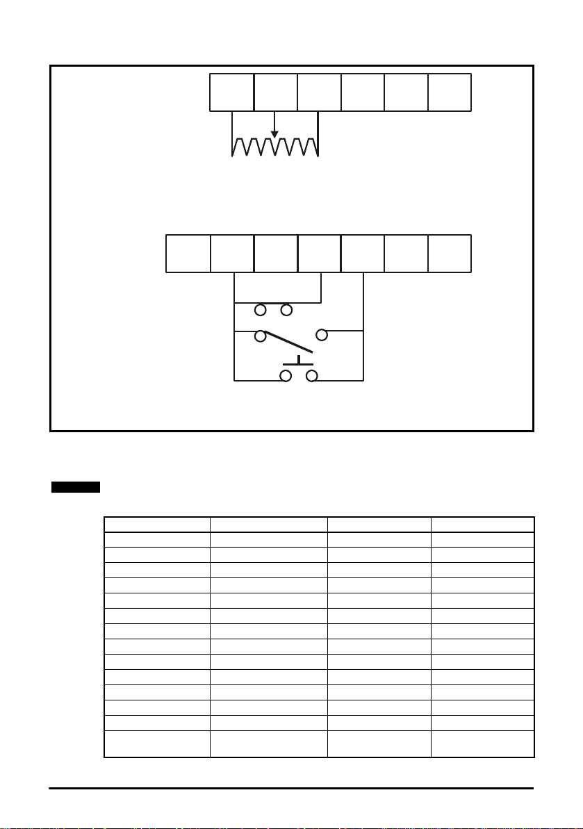
1.19 Drive parameter list for using a potentiometer to control
T1 T2 T3 T4 T5 T6
B1 B2 B3 B4 B5 B6 B7
Drive enabled (normally closed)
Stop signal switch on camshaft
(normally closed)
Momentary Start
Radio Shack Pt.No 275-324
IMC Pt.No 87C08062019510
Radio Shack Pt.No 275-609
Single turn wire-wound potentiometer 2K to 10 K
Ω (
2W)
A project box 5 x 2-1/2 x 2 Radio Shack Pt.No 270-1803
can be used to house the switches and the potentiometer
NOTE
speed with a proximity switch for cycling
The speed range of the potentiometer is from 0 to the Pr 02 value.
Parameter Description Value Units
Pr 01 Minimum set speed 0 Hz
Pr 02 Maximum set speed 60 Hz
Pr 03 Acceleration rate 1 0.1 s/100Hz
Pr 04 Deceleration rate 1 0.2 s/100Hz
Pr 05 Drive configuration 1:Av.Pr
Pr 06 Motor rated current - A (from motor plate)
Pr 07 Motor rated full load rpm 0 RPM (always 0)
Pr 08 Motor rated voltage - V (from motor plate)
Pr 09 Motor rated power factor - (from motor plate)
Pr 10 Security status 0:L1
Pr 11 Start / stop logic select 0
Pr 12 Brake controller enable 0:dis
Pr 15 Jog reference 1.5 Hz
Pr 16
Analog input 1 mode
(terminal T2)
6:VoLt
14 IM-pAC Getting Started Guide
www.camcoindex.com | www.destaco.com Issue Number: 5
Page 15

Parameter Description Value Units
Pr 17
Allow negative
references
OFF
Pr 18 Preset speed 1 0 Hz
Pr 19 Preset speed 2 0 Hz
Pr 20 Preset speed 3 0 Hz
Pr 21 Preset speed 4 0 Hz
Pr 22 Load display units Ld
Pr 23 Speed display units 0:Fr
Pr 24 Customer defined scaling 1
Pr 25 User security code 0
Pr 27
Power-up keypad
reference
0
Pr 28 Parameter cloning 0:no
Pr 29 Load defaults 0:no
Pr 30 Ramp mode select 3:FSt.Hv
Pr 31 Stopping mode select 1
Pr 32 Dynamic V to f select OFF
Pr 33
Catch a spinning motor
select
0
Pr 34 Terminal B7 mode select 0:dig
Pr 35
Pr 36
Pr 37
Digital output control
(terminal B3)
Analog output control
(terminal Bi)
Maximum switching
frequency
0:n=0
0:Fr
12 kHz
Pr 38 Auto-tune 0
Pr 39 Motor rated frequency - Hz (from motor plate)
Pr 40 Number of motor poles 2:4 pole
Pr 41 Voltage mode select 2:Fd
Pr 42
Low frequency voltage
boost
4
Pr 43 Serial comms baud rate 19.2
Pr 44 Serial comms address 1
Pr 45 Software version 1.04
Pr 46
Pr 47
Brake release current
threshold
Brake apply current
threshold
50
10
Pr 48 Brake release frequency 1 Hz
Pr 49 Brake apply frequency 2 Hz
Pr 50 Pre-brake release delay 0 s
Pr 51 Post brake release delay 0 s
Read Me First
Instructions
Safety Information Rating Data
Mechanical
Installation
Electrical Installation Keypad and Display Parameters Diagnostics
Diagram for wiring switches to the IM-pAC control terminals (cover has been removed)
for cycling on demand using a limit switch, momentary start and inverter duty motor.
Index drive is in middle of dwell position see section 1.16 Indexer drive shown in middle
of dwell position diagram. on page 9.
IM-pAC Getting Started Guide 15
Issue Number: 5 www.camcoindex.com | www.destaco.com
Information
UL Listing
Page 16

16 IM-pAC Getting Started Guide
www.camcoindex.com | www.destaco.com Issue Number: 5
Page 17

1.20 Drive parameter list for using a potentiometer and switch
NOTE
selected presets to control speed
The speed range of the potentiometer is from 0 to the Pr 02 value.
Read Me First
Instructions
Parameter Description Value Units
Pr 01 Minimum set speed 0 Hz
Pr 02 Maximum set speed 60 Hz
Pr 03 Acceleration rate 1 0.1 s/100Hz
Pr 04 Deceleration rate 1 0.2 s/100Hz
Pr 05 Drive configuration 1:Av.Pr
Pr 06 Motor rated current - A (from motor plate)
Pr 07 Motor rated full load rpm 0 RPM (always 0)
Pr 08 Motor rated voltage - V (from motor plate)
Pr 09 Motor rated power factor - (from motor plate)
Pr 10 Security status 2:L3
Pr 11 Start / stop logic select 0
Pr 12 Brake controller enable 0:dis
Pr 15 Jog reference 1.5 Hz
Pr 16
Pr 17
Pr 18 Preset speed 1 0 Hz
Pr 19 Preset speed 2 20 Hz
Pr 20 Preset speed 3 30 Hz
Pr 21 Preset speed 4 40 Hz
Pr 22 Load display units Ld
Pr 23 Speed display units 0:Fr
Pr 24 Customer defined scaling 1
Pr 25 User security code 0
Pr 27
Pr 28 Parameter cloning 0:no
Pr 29 Load defaults 0:no
Pr 30 Ramp mode select 3:FSt.Hv
Pr 31 Stopping mode select 1
Pr 32 Dynamic V to f select OFF
Pr 33
Pr 34 Terminal B7 mode select 0:dig
Pr 35
Pr 36
Pr 37
Pr 38 Auto-tune 0
Pr 39 Motor rated frequency - Hz (from motor plate)
Analog input 1 mode
(terminal T2)
Allow negative
references
Power-up keypad
reference
Catch a spinning motor
select
Digital output control
(terminal B3)
Analog output control
(terminal Bi)
Maximum switching
frequency
6:VoLt
OFF
0
0
8:User
0:Fr
12 kHz
Safety Information Rating Data
Mechanical
Installation
Electrical Installation Keypad and Display Parameters Diagnostics
Information
UL Listing
IM-pAC Getting Started Guide 17
Issue Number: 5 www.camcoindex.com | www.destaco.com
Page 18

Parameter Description Value Units
Pr 40 Number of motor poles 2:4 pole
Pr 41 Voltage mode select 2:Fd
Pr 42
Pr 43 Serial comms baud rate 19.2
Pr 44 Serial comms address 1
Pr 45 Software version 1.04
Pr 46
Pr 47
Pr 48 Brake release frequency 1 Hz
Pr 49 Brake apply frequency 2 Hz
Pr 50 Pre-brake release delay 0 s
Pr 51 Post brake release delay 0 s
Low frequency voltage
boost
Brake release current
threshold
Brake apply current
threshold
4
50
10
18 IM-pAC Getting Started Guide
www.camcoindex.com | www.destaco.com Issue Number: 5
Page 19
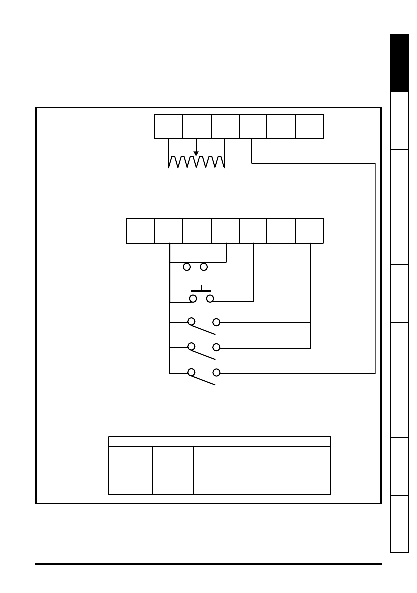
1.21 Drive wiring for using a potentiometer and switch selected
T1 T2 T3 T4 T5 T6
B1 B2 B3 B4 B5 B6 B7
Drive enabled (normally closed)
Momentary Start
Radio Shack.
Pt.No 275-324
Radio Shack
Pt.No 275-609
Single turn wire-wound potentiometer 2K to 10 K
Ω (
2W)
A project box 5 x 2-1/2 x 2 Radio Shack Pt.No 270-1803
can be used to house the switches and the potentiometer
Reference select 2 B7 SPST switch
Reference select 1 T4 SPST switch
Radio shack
Pt.No 275-324
Radio shack Pt.No 275-324
Switch logic
T4
Open
Open
Closed
Closed
B7
Open
Closed
Open
Closed
Reference Selected
Pr A1 speed potentiometer
Pr Preset speed 2
Pr Preset speed 3
Pr Preset speed 4
18
19
20
21
IMC Pt.No
87C08062019510
Stop signal switch on camshaft
(normally closed)
presets to control speed
Diagram for wiring switches to the IM-pAC control terminals (cover has been removed)
for cycling on demand using a limit switch, momentary start and inverter duty motor.
Index drive is in middle of dwell position see section 1.16 Indexer drive shown in middle
of dwell position diagram on page 10.
Read Me First
Instructions
Safety Information Rating Data
Mechanical
Installation
Electrical Installation Keypad and Display Parameters Diagnostics
IM-pAC Getting Started Guide 19
Issue Number: 5 www.camcoindex.com | www.destaco.com
Information
UL Listing
Page 20

1.22 Drive parameter list for using a PLC to control speed
NOTE
10 Vdc applied to T1 and T2 will run the motor to the Pr 02 Maximum set speed. The
speed is proportional to the applied voltage.
Parameter Description Value Units
Pr 01 Minimum set speed 0 Hz
Pr 02 Maximum set speed 60 Hz
Pr 03 Acceleration rate 1 0.1 s/100Hz
Pr 04 Deceleration rate 1 0.2 s/100Hz
Pr 05 Drive configuration 2:AI.Pr
Pr 06 Motor rated current - A (from motor plate)
Pr 07 Motor rated full load rpm 0 RPM (always 0)
Pr 08 Motor rated voltage - V (from motor plate)
Pr 09 Motor rated power factor - (from motor plate)
Pr 10 Security status 0:L1
Pr 11 Start / stop logic select 0
Pr 12 Brake controller enable 0:dis
Pr 15 Jog reference 1.5 Hz
Pr 16
Pr 17
Pr 18 Preset speed 1 0 Hz
Pr 19 Preset speed 2 0 Hz
Pr 20 Preset speed 3 0 Hz
Pr 21 Preset speed 4 0 Hz
Pr 22 Load display units Ld
Pr 23 Speed display units 0:Fr
Pr 24 Customer defined scaling 1
Pr 25 User security code 0
Pr 27
Pr 28 Parameter cloning 0:no
Pr 29 Load defaults 0:no
Pr 30 Ramp mode select 3:FSt.Hv
Pr 31 Stopping mode select 1
Pr 32 Dynamic V to f select OFF
Pr 33
Pr 34 Terminal B7 mode select 0:dig
Pr 35
Pr 36
Pr 37
Pr 38 Auto-tune 0
Pr 39 Motor rated frequency - Hz (from motor plate)
Pr 40 Number of motor poles 2:4 pole
Analog input 1 mode
(terminal T2)
Allow negative
references
Power-up keypad
reference
Catch a spinning motor
select
Digital output control
(terminal B3)
Analog output control
(terminal Bi)
Maximum switching
frequency
6:VoLt
OFF
0
0
0:n=0
0:Fr
12 kHz
20 IM-pAC Getting Started Guide
www.camcoindex.com | www.destaco.com Issue Number: 5
Page 21
Parameter Description Value Units
T1 T2 T3 T4 T5 T6
B1 B2 B3 B4 B5 B6 B7
Drive enabled (normally closed)
Stop signal switch on camshaft
(normally closed)
Momentary Start
Radio Shack Pt.No 275-324
IMC Pt.No 87C08062019510
Radio Shack Pt.No 275-609
A project box 5 x 2-1/2 x 2 Radio Shack Pt.No 270-1803
can be used to house the switches and the potentiometer
0
+ 10 Vdc Max
Pr 41 Voltage mode select 2:Fd
Pr 42
Pr 43 Serial comms baud rate 19.2
Pr 44 Serial comms address 1
Pr 45 Software version 1.04
Pr 46
Pr 47
Pr 48 Brake release frequency 1 Hz
Pr 49 Brake apply frequency 2 Hz
Pr 50 Pre-brake release delay 0 s
Pr 51 Post brake release delay 0 s
Low frequency voltage
boost
Brake release current
threshold
Brake apply current
threshold
50
10
1.23 Drive wiring for a PLC to control speed
Diagram for wiring switches to the IM-pAC control terminals (cover has been removed)
for cycling on demand using a limit switch, momentary start and inverter duty motor.
Index drive is in middle of dwell position see section 1.16 Indexer drive shown in middle
of dwell position diagram on page 10.
Read Me First
Instructions
4
Safety Information Rating Data
Mechanical
Installation
Electrical Installation Keypad and Display Parameters Diagnostics
IM-pAC Getting Started Guide 21
Issue Number: 5 www.camcoindex.com | www.destaco.com
Information
UL Listing
Page 22

1.24 How to configure the IM-pAC drive to trip for a current ove r-
WARNING
load.
The current overload configuration will protect the index drive only and is not meant to
be a means of protecting any personnel or tooling. Always make sure that no person is
near the indexer and the indexer is clear of any obstructions before operating the drive
while testing the configuration settings or during normal operation.
Overview
The IM-pAC drive is factory preset to constantly monitor the current seen by the motor
and the drive will trip if the accumulated motor current values over time exceed a set
value. This is a calculation and does not require a wired motor themistor input.
The motor thermal constant parameter controls the drive trip and is set at a default value
of 89. The 89 value will allow the motor to draw 1.65 times its rated amperage for a little
over 40 seconds before the drive will trip. When the drive trips the drive healthy relay
(T5 and T6 contacts) will open to signal the trip. You will wire your PLC input line
through the drive healthy relay to signal the trip. When the drive is tripped the display
will show [It.AC]
The overload configuration scheme for the IM-pAC uses a thermal constant parameter
set to 1 (the minimum) and a symmetrical current value set for the application. Index
drives 601RDM and 902RDM have been tested at IMC using a thermal constant of 1
and a symmetrical current constant of 165. The drives successfully tripped without any
indexer damage for a jammed dwell or an obstruction encountered during the middle of
the index.
For now based upon our test results we are limiting use of this overload
configuration to applications under 1 horsepower demand.
The following steps describe how to view the torque required for you application and
how to change the symmetrical current and motor constant values to protect your
indexer from damage.
We are assuming that you have already entered in the correct parameter values for
Pr 39, Pr 06, Pr 08 and Pr 09 from your motor name plate.
We also assume you have placed the jumpers and wired your motor for the correct
applied voltage. Remember the control voltage must be greater than or equal to the
motor's voltage.
The instructions in this document are detailed and should be read carefully before
proceeding. In addition we have included as a reference on the last page of this paper a
page from the IM-pAC manual showing how to view and change parameters from the
keypad.
Parameters Used
Parameter Description
Pr 10 Security level - default is L1
Pr 88 Current magnitude - current demand for your application
Pr 4.07 Symmetrical current value - default is 165 percent
Pr 4.15 Motor thermal constant - default is 89
The key pad display should show [ih 0.0] and not [rd 0.0] when you start. You must put
the control into inhibit mode by opening B2 and B4.
22 IM-pAC Getting Started Guide
www.camcoindex.com | www.destaco.com Issue Number: 5
Page 23

Step 1 - Changing the security level.
Press the M (memory) button on the key pad. The display will start to show the flashing
parameter numbers on the left side and the non-flashing parameter values on the right
side. Now, press the /\ button to the right of the M button several time until the left
parameter value changes to 10. If you happen to go passed Pr 10 then use the \/ key to
return to Pr 10. Once you are at the flashing Pr 10, press the M key and the parameter
value on the right L1 should start to flash.
Press the /\ key 2 times until a value of L3 appears [10 L3].
Press the M key 2 times to return the display back to [ih 0.0].
Step 2 - How to map the motor thermal constant to Pr 61.
Press the M button on the key pad. Now, press the \/ button until the left parameter
value changes to Pr 71. If you happen to go passed Pr 71, then use the /\ key to return
to Pr 71. Once you are at the flashing Pr 71, press the M key and the parameter value
on the right 0.0 should start to flash.
Press the /\ key several times until a value of 4.15 appears [71 4.15].
Press the M key 2 times to return the display back to the [ih 0.0].
Step 3 - How to map the symmetrical current value to Pr 62.
Press the M button on the key pad. Now, press the \/ button until the left parameter
value changes to Pr 72. If you happen to go passed Pr 72, then use the /\ key to return
to Pr 72. Once you are at the flashing Pr 72, press the M key and the parameter value
on the right 0.0 should start to flash.
Press the /\ key several times until a value of 4.07 appears [72 4.07].
Press the M key 2 times to return the display back to [ih 0.0].
Step 4 - How to view the current magnitude for your application.
See the Safety Warning on the first page before continuing.
The key pad display should show [rd 0.0] when you start. If the display shows [ih 0.0]
you must take the control out of inhibit mode by closing B2 and B4. Make sure you are
set to run at your intended speed and load. You will now run the motor continuously in
order to view and record the maximum current demand for your application. In order to
run the motor continuously you must keep connection B2 and B5 closed. You can do
this with a simple jumper. Once the motor and drive are running, press the M button on
the key pad. Now, press the \/ button until the left parameter value changes to Pr 88. If
you happen to go passed Pr 88, then use the /\ key to return to Pr 88. The maximum
value for Pr 88 is the maximum value for your application. You will use this amperage
value in step 6 as part of a calculation for the symmetrical current value.
Press the M key 2 times to return the display back to the [rd 0.0].
You can now remove the jumper between B2 and B5.
Step 5 - How to change the motor thermal constant Pr 61.
Press the M button on the key pad. Now, press the \/ button several times until the left
parameter value changes to Pr 61. If you happen to go passed Pr 61, then use the /\
key to return to Pr 61. Once you are at the flashing Pr 61, press the M key and the
parameter value on the right Pr 89 should start to flash.
Press the \/ key several times until a value of 1 appears [61 1].
Press the M key 2 times to return the display back to the [ih 0.0].
Read Me First
Instructions
Safety Information Rating Data
Mechanical
Installation
Electrical Installation Keypad and Display Parameters Diagnostics
Information
UL Listing
IM-pAC Getting Started Guide 23
Issue Number: 5 www.camcoindex.com | www.destaco.com
Page 24

Step 6 - How to change the symmetrical current value Pr 62.
NOTE
NOTE
The new symmetrical current value is calculated by the following method.
Take the value of the maximum current value observed from step 4 and divide it by the
motor rated current value (Pr 06 or the name plate value) and then multiply it by 100.
e.g. XXX = 0.94 / 1.14 x 100 = 83
This means we would like the drive to fault at 83 percent of the motor rated current. We
may want to add a few percent to this to avoid some nuisance trips so we will round this
up to 100.
Never exceed a value of 165 for the symmetrical current or raise the value of Pr 06 above
the name plate value for the applied voltage.
Press the M button on the key pad. Now, press the \/ button several until the left
parameter value changes to Pr 62. If you happen to go passed Pr 62, then use the /\
key to return to Pr 62. Once you are at the flashing Pr 62, press the M key and the
parameter value on the right 0.0 should start to flash. Press the /\ key several times until
the value of XXX appears [62 XXX.0]. (For our revised calculated example we would
have entered 100 [62 100.0].) Press the M key 2 times to return the display back to the
[ih 0.0]. The drive has now been configured to trip during a current overload. You can
take the drive out of the inhibit state by closing connections B2 and B4.
How to manually recover from an overload.
See the Safety Warning on the first page before starting this step.
You must put the control into inhibit mode by opening B2 and B4.
You must recover from the overload condition by returning the indexer to a dwell
position at a reduced speed. You can reduce the motor speed by either changing Pr 18
or turning the speed pot down if you have one wired.
Press the button on the key pad with the red circle.
Put the control out of inhibit mode by closing B2 and B4. If the index drive does not start,
then send a start signal. Once you are in a dwell position reset the motor preset value
back to its original value or return the speed pot back to its normal setting.
1.25 Drive parameter list for a motor reversing application
You should have a copy of the data sheet for the indexer application in order to set Pr 18
correctly. You must change Pr 10 (Security Level) to 2 or L3 before you can change
Pr 18, the preset speed. On the data sheet you will find the motor speed for your
application and the motor's rated rpm.
Use the following calculation to determine Pr 18.
Pr 18 = Pr 39 x Motor Speed for Application / Motor Rated RPM
Pr 18 = 60 hz x 1650 rpm / 1750 rpm = 57 hz (round all values up to a whole number)
24 IM-pAC Getting Started Guide
www.camcoindex.com | www.destaco.com Issue Number: 5
Page 25

Parameter Description Value Units
Pr 01 Minimum set speed 0 Hz
Pr 02 Maximum set speed 60 Hz
Pr 03 Acceleration rate 1 0.1 s/100Hz
Pr 04 Deceleration rate 1 0.2 s/100Hz
Pr 05 Drive configuration 3:Pr
Pr 06 Motor rated current - A (from motor plate)
Pr 07 Motor rated full load rpm 0 RPM (always 0)
Pr 08 Motor rated voltage - V (from motor plate)
Pr 09 Motor rated power factor - (from motor plate)
Pr 10 Security status 2:L3
Pr 11 Start / stop logic select 2
Pr 12 Brake controller enable 0:dis
Pr 15 Jog reference 1.5 Hz
Pr 16
Pr 17
Analog input 1 mode
(terminal T2)
Allow negative
references
6:VoLt
OFF
Pr 18 Preset speed 1 50 Hz
Pr 19 Preset speed 2 0 Hz
Pr 20 Preset speed 3 0 Hz
Pr 21 Preset speed 4 0 Hz
Pr 22 Load display units Ld
Pr 23 Speed display units 0:Fr
Pr 24 Customer defined scaling 1
Pr 25 User security code 0
Pr 27
Power-up keypad
reference
0
Pr 28 Parameter cloning 0:no
Pr 29 Load defaults 0:no
Pr 30 Ramp mode select 3:FSt.Hv
Pr 31 Stopping mode select 1
Pr 32 Dynamic V to f select OFF
Pr 33
Catch a spinning motor
select
0
Pr 34 Terminal B7 mode select 0:dig
Pr 35
Pr 36
Pr 37
Digital output control
(terminal B3)
Analog output control
(terminal Bi)
Maximum switching
frequency
0:n=0
0:Fr
12 kHz
Pr 38 Auto-tune 0
Pr 39 Motor rated frequency - Hz (from motor plate)
Pr 40 Number of motor poles 2:4 pole
Pr 41 Voltage mode select 2:Fd
Pr 42
Low frequency voltage
boost
4
Pr 43 Serial comms baud rate 19.2
Read Me First
Instructions
Safety Information Rating Data
Mechanical
Installation
Electrical Installation Keypad and Display Parameters Diagnostics
Information
UL Listing
IM-pAC Getting Started Guide 25
Issue Number: 5 www.camcoindex.com | www.destaco.com
Page 26

Parameter Description Value Units
Pr 44 Serial comms address 1
Pr 45 Software version 1.04
Pr 46
Pr 47
Pr 48 Brake release frequency 1 Hz
Pr 49 Brake apply frequency 2 Hz
Pr 50 Pre-brake release delay 0 s
Pr 51 Post brake release delay 0 s
Brake release current
threshold
Brake apply current
threshold
50
10
26 IM-pAC Getting Started Guide
www.camcoindex.com | www.destaco.com Issue Number: 5
Page 27

1.26 Drive wiring for a motor reversing application.
T1 T2 T3 T4 T5 T6
B1 B2 B3 B4 B5 B6 B7
Drive enabled (normally closed)
Momentary Start
Radio Shack Pt.No 275-324
Radio Shack.Pt.No 275-609
Stop signal switch on camshaft
(normally closed)
IMC Pt.No 87C08062019510
Forward / Reverse
You must provide the logic which will open and close the B2-B6 terminals.
Opening or closing the B2-B6 terminals with parameter Pr set to 2 will reverse
the motor direction for the next move.
There must be two limit switch cams mounted to signal the motor stop for the
middle of dwell,
one for the forward motion and the other for the reverse, see below.
11
Diagram for wiring switches to the IM-pAC control terminals (cover has been removed)
for cycling on demand using a limit switch, momentary start and inverter duty motor.
Index drive is in middle of dwell position see section 1.16 Indexer drive shown in middle
of dwell position diagram on page 10.
Read Me First
Instructions
Safety Information Rating Data
Mechanical
Installation
Electrical Installation Keypad and Display Parameters Diagnostics
Information
UL Listing
IM-pAC Getting Started Guide 27
Issue Number: 5 www.camcoindex.com | www.destaco.com
Page 28

1.27 Drive parameter list for a 24Vdc brake motor
Parameter Description Value Units
Pr 01 Minimum set speed 0 Hz
Pr 02 Maximum set speed 60 Hz
Pr 03 Acceleration rate 1 0.1 s/100Hz
Pr 04 Deceleration rate 1 0.2 s/100Hz
Pr 05 Drive configuration 3:Pr
Pr 06 Motor rated current - A (from motor plate)
Pr 07 Motor rated full load rpm 0 RPM (always 0)
Pr 08 Motor rated voltage - V (from motor plate)
Pr 09 Motor rated power factor - (from motor plate)
Pr 10 Security status 2:L3
Pr 11 Start / stop logic select 0
Pr 12 Brake controller enable 1:rEL
Pr 15 Jog reference 1.5 Hz
Pr 16
Pr 17
Pr 18 Preset speed 1 60 Hz
Pr 19 Preset speed 2 0 Hz
Pr 20 Preset speed 3 0 Hz
Pr 21 Preset speed 4 0 Hz
Pr 22 Load display units Ld
Pr 23 Speed display units 0:Fr
Pr 24 Customer defined scaling 1
Pr 25 User security code 0
Pr 27
Pr 28 Parameter cloning 0:no
Pr 29 Load defaults 0:no
Pr 30 Ramp mode select 3:FSt.Hv
Pr 31 Stopping mode select 1
Pr 32 Dynamic V to f select OFF
Pr 33
Pr 34 Terminal B7 mode select 0:dig
Pr 35
Pr 36
Pr 37
Pr 38 Auto-tune 0
Pr 39 Motor rated frequency - Hz (from motor plate)
Pr 40 Number of motor poles 2:4 pole
Pr 41 Voltage mode select 2:Fd
Pr 42
Analog input 1 mode
(terminal T2)
Allow negative
references
Power-up keypad
reference
Catch a spinning motor
select
Digital output control
(terminal B3)
Analog output control
(terminal Bi)
Maximum switching
frequency
Low frequency voltage
boost
6:VoLt
OFF
0
0
0:n=0
0:Fr
12 kHz
4
28 IM-pAC Getting Started Guide
www.camcoindex.com | www.destaco.com Issue Number: 5
Page 29

Parameter Description Value Units
Pr 43 Serial comms baud rate 19.2
Pr 44 Serial comms address 1
Pr 45 Software version 1.04
Pr 46
Pr 47
Brake release current
threshold
Brake apply current
threshold
50
10
Pr 48 Brake release frequency 1 Hz
Pr 49 Brake apply frequency 2 Hz
Pr 50 Pre-brake release delay 0 s
Pr 51 Post brake release delay 0 s
Read Me First
Instructions
Safety Information Rating Data
Mechanical
Installation
Electrical Installation Keypad and Display Parameters Diagnostics
IM-pAC Getting Started Guide 29
Issue Number: 5 www.camcoindex.com | www.destaco.com
Information
UL Listing
Page 30

1.28 Drive wiring for a 24Vdc brake motor
1
2
3
4
5
Brake power supply
24Vdc 2.1A
120 - 240 Vac 50 -60 Hz
IMC Pt.No 99A86986000000
White
Red
Blue
BSG Module
+ 24 Vdc
T1 T2 T3 T4 T5 T6
B1 B2 B3 B4 B5
B6
B7
Drive enabled (normally closed)
Momentary Start
Radio Shack Pt.No 275-324
Radio Shack Pt.No 275-609
Limit or proximity switch
for cycling indexer
(open to stop or E-stop)
T5 - T6 build in relay 240 Vac / 30 Vdc - 2A / 6A (resistive)
stop and E-stop switches should have the same rating
Motor
IM-pAC Drive
Diagram for wiring switches to the IM-pAC control terminals (cover has been removed)
for cycling on demand using a limit switch, momentary start and inverter duty motor.
Index drive is in middle of dwell position see section 1.16 Indexer drive shown in middle
of dwell position diagram on page 10.
30 IM-pAC Getting Started Guide
www.camcoindex.com | www.destaco.com Issue Number: 5
Page 31

1.29 Drive and Options part numbers
Table 1-1 Sizes
IMC Part Number
92C85797010000 A 1 HP 0.75 kW 200 - 240V 0.75 kW single phase 48-62 hz
92C85797020000 B 1 HP 0.75 kW 380 - 460V 0.75 kW three phase 48-62 hz
2010000 B 1.5 HP 1.1 kW 200 - 240V 1.1 kW single phase 48-62 hz
92B9048
92B90482020000 B 2 HP 1.5 kW 200 - 240V 1.5 kW single phase 48-62 hz
92B90482030000 C 3 HP 2.2 kW 200 - 240V 2.2 kW single phase 48-62 hz
92B90482040000 B 2 HP 1.5 kW 380 - 460V 1.5 kW three phase 48-62 hz
92B90482050000 C 3 HP 2.2
92B90482060000 C
92B9048207000
92B9048208000
92B90482090000 B 1.5
Drive
size
0 B 1 HP
0 B 1.5
Motor Power Rating
5 HP 4.0
kW 380 - 460V 2.2 kW three phase 48-62 hz
kW 380 - 460V 4.0 kW three phase 48-62 hz
0.75 kW 100-120V 0.75 kW single phase 48-62 hz
HP 1.1 kW 100-120V 1.1 kW single phase 48-62 hz
HP 1.1 kW 380 - 460V 1.1 kW three phase 48-62 hz
Read Me First
Instructions
Safety Information Rating Data
Table 1-2 Options
t Number D
IMC Par
92C857970110000 Profibus option module size B or C only
92C857970120000 DeviceNet option module size B or C only
92C857970130000 CAN Open option module size B or C only
92C857970140000 Interbus Option module size B or C only
92C857970150000 Ethernet Option module size B or C only
92C857970160000 Additional I/O option module size B or C only
92C857970170000 Additional I/O with Real Time Clock option module size B or C only
92C857970180000 Cloning memory option
92C857970190000 PLC ladder logic option
92C857970200000
92C857970210000
92C857970220000
92C857970230000 Kit consisting of plastic top and side covers to comply with IP4X for size A
92C857970240000 Kit consisting of plastic top and side covers to comply with IP4X for size B
92C857970250000 Kit consisting of plastic top and side covers to comply with IP4X for size C
92C857970260000 Cable strain relief - fits sizes A, B, or C
92C857970270000 Communications cable for connecting the drive to a PC
92C857970280000 LCD Text keypad IP54
92C857970290000 LED Remote keypad IP54
92C857970300000 Filter for IM-pAC size A
92C857970310000 Filter for IM-pAC size B
92C857970320000 Line reactor for IM-pAC size A
92C857970330000 Line reactor for IM-pAC size B
Kit consisting of plastic top and side covers and steel bottom conduit entry
cover to comply with UL Type 1 for size A
Kit consisting of plastic top and side covers and steel bottom conduit entry
cover to comply with UL Type 1 for size B
Kit consisting of plastic top and side covers and steel bottom conduit entry
cover to comply with UL Type 1 for size C
escription
Mechanical
Installation
Electrical Installation Keypad and Display Parameters Diagnostics
Information
UL Listing
IM-pAC Getting Started Guide 31
Issue Number: 5 www.camcoindex.com | www.destaco.com
Page 32

2 Safety Information
WARNING
CAUTION
NOTE
2.1 Warnings, Cautions and Notes
A Warning contains information, which is essential for avoiding a safety hazard.
A Caution contains information, which is necessary for avoiding a risk of damage to the
product or other equipment.
A Note contains information, which helps to ensure correct operation of the product.
2.2 Electrical Safety - general warning
The voltages used in the drive can cause severe electrical shock and/or burns, and
could be lethal. Extreme care is necessary at all times when working with or adjacent to
the drive.
Specific warnings are given at the relevant places in this guide.
2.3 System design and safety of personnel
The drive is intended as a component for professional incorporation into complete
equipment or system. If installed incorrectly, the drive may present a safety hazard.
The drive uses high voltages and currents, carries a high level of stored electrical
energy, and is used to control equipment which can cause injury.
System design, installation, commissioning and maintenance must be carried out by
personnel who have the necessary training and experience. They must read this safety
information and this guide carefully.
The STOP and START controls or electrical inputs of the drive must not be relied
upon to ensure safety of personnel. They do not isolate dangerous voltages from
the output of the drive or from any external option unit. The supply must be
disconnected by an approved electrical isolation device before gaining access to
the electrical connections.
The drive is not intended to be used for safety-related functions.
Careful consideration must be given to the function of the drive which might result in a
hazard, either through its intended behaviour or through incorrect operation due to a
fault. In any application where a malfunction of the drive or its control system could lead
to or allow damage, loss or injury, a risk analysis must be carried out, and where
necessary, further measures taken to reduce the risk - for example, an over-speed
protection device in case of failure of the speed control, or a fail-safe mechanical brake
in case of loss of motor braking.
2.4 Environmental Limit s
Instructions within the supplied data and information within the IM-pAC Technical Data
Guide regarding transport, storage, installation and the use of the drive must be
complied with, including the specified environmental limits. Drives must not be
subjected to excessive physical force.
32 IM-pAC Getting Started Guide
www.camcoindex.com | www.destaco.com Issue Number: 5
Page 33

2.5 Access
Access must be restricted to authorized personnel only. Safety regulations which apply
at the place of use must be complied with.
The IP (Ingress Protection) rating of the drive is installation dependant.
Read Me First
Instructions
2.6 Compliance and regulations
The installer is responsible for complying with all relevant regulations, such as national
wiring regulations, accident prevention regulations and electromagnetic compatibility
(EMC) regulations. Particular attention must be given to the cross-sectional areas of
conductors, the selection of fuses and other protection, and protective ground (earth)
connections.
The IM-pAC Technical Data Guide contains instructions for achieving compliance with
specific EMC standards.
Within the European Union, all machinery in which this product is used must comply
with the following directives:
98/37/EC: Safety of machinery
89/336/EEC: Electromagnetic compatibility
2.7 Motor
Ensure the motor is installed in accordance with the manufacturer's recommendations.
Ensure the motor shaft is not exposed.
Standard squirrel cage induction motors are designed for single speed operation. If it is
intended to use the capability of a drive to run a motor at speeds above its designed
maximum, it is strongly recommended that the manufacturer is consulted first.
Low speeds may cause the motor to overheat because the cooling fan becomes less
effective. The motor should be installed with a protection thermistor. If necessary, an
electric force vent fan should be used.
The values of the motor parameters set in the drive affect the protection of the motor.
The default values in the drive should not be relied upon.
It is essential that the correct value is entered into parameter 06, motor rated current.
This affects the thermal protection of the motor.
2.8 Adjusting parameters
Some parameters have a profound effect on the operation of the drive. They must not
be altered without careful consideration of the impact on the controlled system.
Measures must be taken to prevent unwanted changes due to error or tampering.
Safety Information
Rating Data
Mechanical
Installation
Electrical Installation Keypad and Display Parameters Diagnostics
2.9 Electrical installation
2.9.1 Electric shock risk
The voltages present in the following locations can cause severe electric shock and may
be lethal:
• AC supply cables and connections
• DC bus, dynamic brake cables and connections
• Output cables and connections
• Many internal parts of the drive, and external option units
Unless otherwise indicated, control terminals are single insulated and must not be
touched.
IM-pAC Getting Started Guide 33
Issue Number: 5 www.camcoindex.com | www.destaco.com
Information
UL Listing
Page 34

2.9.2 Isolation device
The AC supply must be disconnected from the drive using an approved isolation device
before any cover is removed from the drive or before any servicing work is performed.
2.9.3 STOP function
The STOP function does not remove dangerous voltages from the drive, the motor or
any external option units.
2.9.4 Stored charge
The drive contains capacitors that remain charged to a potentially lethal voltage after the
AC supply has been disconnected. If the drive has been energized, the AC supply must
be isolated at least ten minutes before work may continue.
Normally, the capacitors are discharged by an internal resistor. Under certain, unusual
fault conditions, it is possible that the capacitors may fail to discharge, or be prevented
from being discharged by a voltage applied to the output terminals. If the drive has failed
in a manner that causes the display to go blank immediately, it is possible the capacitors
will not be discharged. In this case, consult IMC or their authorized distributor.
2.9.5 Equipment supplied by plug and socket
Special attention must be given if the drive is installed in equipment which is connected
to the AC supply by a plug and socket. The AC supply terminals of the drive are
connected to the internal capacitors through rectifier diodes which are not intended to
give safety isolation. If the plug terminals can be touched when the plug is disconnected
from the socket, a means of automatically isolating the plug from the drive must be used
(e.g. a latching relay).
2.9.6 Ground leakage current
The drive is supplied with an internal EMC filter capacitor installed. If the input voltage to
the drive is supplied through an ELCB or RCD, these may trip due to the ground
leakage current. See section 5.3.1 Internal EMC filter on page 41 for further information
and how to disconnect the internal EMC capacitor.
34 IM-pAC Getting Started Guide
www.camcoindex.com | www.destaco.com Issue Number: 5
Page 35

3Rating Data
Table 3-1 120V drive
Nominal
Model Number
92B90482070000 1.0 0.75
92B90482080000 1.5 1.1
Motor Power
hp kW 1ph Heavy Duty
Table 3-2 200V drive
Nominal
Model Number
92C85797010000 1.0 0.75
92B9048
2010000 1.5 1.1
92B90482020000 2.0 1.5
2030000 3.0 2.2
92B9048
Motor Power
hp kW 1ph Heavy Duty
Table 3-3 400V drive
Nominal
Model Number
92C85797020000 1.0 0.75
92B9048209000 1.5 1.
92B90482040000 2.0 1.5
92B90482050000 2.2 3
92B9048
2060000 4 5
Motor
Power
hp kW 3ph Heavy Duty
Supply voltage
and frequency
1 phase
10
o 120V ±10%
0 t
48 to 62 hz
1 phase
to 1
100
48 to 62 hz
Supply voltage
and frequency
1 phase
200 to 240V ±10%
48 to 62 hz
1 and 3 phase
200 to 240V ±10%
48 to 62 hz
1 and 3 phase
200 to 240V ±10%
48 to 62 hz
1 and 3 phase
200 to 240V ±10%
48 to 62 hz
Supply voltage
and frequency
3 phase
380 to 480V ±10%
48 to 62 hz
3 phase
1
380 to 480V
48 to 62 hz
3 phase
to 480V
380
48 to 62 hz
3 phase
o 480V ±10%
380 t
48 to 62 hz
3 phase
380 to 480V ±10%
48 to 62 hz
20V±10%
±10%
±10%
Typical
full load
input
current
19.6 4 6 28
Typical
full load
input
current
10.5 4.0 6.0 68
14.2 16.7 5.2 7.8 28
17.4 8.7 7.0 10.5 28
23.2 11.9 9.6 14.4 28
Typical
full load
input
current
A
3.1 3.75 2.1 3.2 100
4 4.6 2.8 4.2 100
5.2 5.9 3.8 5.7 100
7.3 9.6 5.1 7.65 100
11.9 13.4 9.0 13.5 55
100% RMS
output
current
A
24 6 7.8 28
A
Maximum
continuous
100% RMS
output
current
c u r r e n t
A
A
A
current for
current for
100%
RMS
output
current
A
150%
overload
60s
A
150%
overload
60s
A
150%
overload
current
for 60s
A
Minimum
Minimum
braking
resistor
value
Ω
braking
resistor
value
Ω
Minimum
braking
resistor
va lu e
Ω
Read Me First
Instructions
Safety Information
Rating Data
Mechanical
Installation
Electrical Installation Keypad and Display Parameters Diagnostics
Information
UL Listing
IM-pAC Getting Started Guide 35
Issue Number: 5 www.camcoindex.com | www.destaco.com
Page 36

NOTE
Output frequency: 0 to 1500Hz
Output voltage: 3 phase, 0 to drive rating (240 or 480Vac maximum set by Pr 08).
The output voltage can be increased by 20% during deceleration. See Pr 30 on page 60
NOTE
The maximum continuous current inputs are used to calculate input cable and fuse
sizing. Where no maximum continuous input currents are indicated, use the typical full
load input current values.
Table 3-4
IMC Part Number
92C85797010000 x N/A 16 N/A 14 1.5 16 1
92C85797020000 N/A x N/A 6 16 1 16 1
20
2B9048
9
92B90482020000 x x 20 16 12 / 14 2.5 / 1.5 16 1
92B90482030000 x x 25 20 10 / 12 4.0 / 2.5 14 1.5
92B90482040000 N/A x N/A 10 16 1 1
92B90482
92B90482060000 N/A x N/A 16 12 2.5 14 1.5
92B90482070000 x N/A 25 N/A 10 4 16
92B90
92B90482090000 N/A x N/A 6 16 1 16 1
NOTE
10000 x x 16 10 12 / 14 2.5 / 1.5 16 1
050000
482080000 x N/A 32 N/A 10 4 16 1
The two cable sizes for 92B90482010000, 92B90482020000 and 92B90482030000
Phases ph Fuse Input cable Motor cable
2
131ph3phAWG
N/A x N/A 16 14 1.5 16 1
mm
AWG
6 1
refer to 1 and 3 phase values respectively.
mm
2
1
36 IM-pAC Getting Started Guide
www.camcoindex.com | www.destaco.com Issue Number: 5
Page 37

4 Mechanical Installation
WARNING
A
B
I
G
D
C
H
E
EFGDC
NOTE
NOTE
Enclosure
The drive is intended to be mounted in an enclosure which prevents access except by
trained and authorized personnel, and which prevents the ingress of contamination. It is
designed for use in an environment classified as pollution degree 2 in accordance with
IEC 60664-1. This means that only dry, non-conducting contamination is acceptable.
Figure 4-1 IM-pAC dimensions
Read Me First
Instructions
Safety Information Rating Data
Mechanical
Installation
Electrical Installation Keypad and Display Parameters Diagnostics
Mounting holes: 4 x M4 holes
Table 4-1 IM-pAC dimensions
Drive
size
A 140 5.51 154 6.06 11 0.43 64 2.52 75 2.95 145 5.71 104 4.09 143 5.63
B 190 7.48 205 8.07 10.9 0.43 65.9 2.6 85 3.35 77 3.0 156 6.15 155.5 6.12 194 7.64
C 240 9.45 258 10.16 10.4 0.41 81.1 3.2 100 3.94 91.9 3.62 173 6.81
ABCDEFGH*I
mm in mm in mm in mm in mm in mm in mm in mm in mm in
*Size C is not DIN rail mountable.
244 9.61
If DIN rail mounting is used in an installation where the drive is to be subjected to shock
or vibration, it is recommended that the bottom mounting screws are used to secure the
drive to the back plate.
If the installation is going to be subjected to heavy shock and vibration, then it is
recommended that the drive is surface mounted rather than DIN rail mounted.
The DIN rail mounting mechanism has been designed so no tools are required to install
and remove the drive from a DIN rail. Please ensure the top mounting lugs are located
correctly on the DIN rail before installation is initiated.
IM-pAC Getting Started Guide 37
Issue Number: 5 www.camcoindex.com | www.destaco.com
Information
UL Listing
Page 38

Figure 4-2 Minimum mounting clearances
AAB
C
C
Display
Smart / Logic
Stick slot
Power
terminals
Control
terminals
Serial
communications
port connector
EMC filter tab
Solutions Module
connector
protective cover
(size B and C
only)
Solutions Module
slot (size B
and C only)
Figure 4-3 Features of the drive (size B illustrated)
38 IM-pAC Getting Started Guide
Drive size
A
B (≥1.1kW) 0 0
C
ABC
mm in mm in mm in
00
10 0.39
www.camcoindex.com | www.destaco.com Issue Number: 5
100 3.94B (≤0.75kW) 10 0.39
Page 39

5 Electrical Installation
Optional
ground
connection
+
L1 L2/N U V W PE
Supply
ground
Optional
line reactor
Braking
resistor
Mains supply
Optional
Thermal
protection
device
Stop
Start/
Reset
PE
Supply
ground
Internal
EMC filter
*
Optional
EMC filter
-DC
Optional ground
connection
Supply
ground
Optional
EMC filter
Optional
line reactor
Fuses
Mains supply
L3/N U V W
+
PE PE
L1 L2
_
L3/N U V WL1 L2
+
PE PE
_
Supply
ground
Internal
EMC filter
*
Star t/
Reset
Braking
resistor
Optional
Thermal
protection
device
Stop
NOTE
NOTE
5.1 Power terminal connections
Figure 5-1 Size A power terminal connections
Figure 5-2 Sizes B and C power terminal connections
Read Me First
Instructions
Safety Information Rating Data
Mechanical
Installation
Installation
Electrical
Keypad and Display Parameters Diagnostics
IM-pAC Getting Started Guide 39
Issue Number: 5 www.camcoindex.com | www.destaco.com
*For further information, see section 5.3.1 Internal EMC filter on page 41.
On the size B 110V drives, the supply should be connected to L1 and L3/N.
The braking terminals are not available on the size A 110V drive.
Information
UL Listing
Page 40

Fuses/MCB
WARNING
WARNING
WARNING
WARNING
NOTE
NOTE
NOTE
The AC supply to the drive must be installed with suitable protection against overload
and short circuits. Failure to observe this requirement will cause risk of fire.
The drive must be grounded by a conductor sufficient to carry the prospective fault
current in the event of a fault. See also the warning in section 5.2 Ground leakage
relating to ground leakage current.
To avoid a fire hazard and maintain validity of the UL listing, adhere to the specified
tightening torques for the power and ground terminals. Refer to the table below.
Frame size Maximum power terminal screw torque
A 0.5 N m / 4.4 lb in
B and C 1.4 N m / 12.1 lb in
Braking resistor: High temperatures and overload protection
Braking resistors can reach high temperatures. Locate braking resistors so that damage
cannot result. Use cable having insulation capable of withstanding the high temperatures.
It is essential that the braking resistor be protected against overload caused by a failure
of the brake control. Unless the resistor has in-built protection, a circuit like those shown
Figure 5-1
in
and
Figure 5-2
should be used, where the thermal protection device
disconnects the AC supply to the drive. Do not use AC relay contacts directly in series
with the braking resistor circuit, because it carries DC.
When connecting single phase to a dual rated 200V unit, use terminals L1 and L3.
For control terminal connections, see Pr 05 on page 51.
For information on the internal EMC filter, see section 5.3.1 Internal EMC filter .
5.2 Ground leakage
The ground leakage current depends upon the internal EMC filter being installed. The
drive is supplied with the filter installed. Instructions for removal of the internal EMC filter
are given in section 5.3.2 Removing the internal EMC filter .
With internal EMC filter installed
30μA DC (10MΩ internal bleed resistor, relevant where DC leakage current is being measured)
Size A
1 phase 110V drives
4mA AC at 110V, 50Hz (proportional to supply voltage and frequency)
1 phase 200V drives
10mA AC at 230V, 50Hz (proportional to supply voltage and frequency)
Size B and C
1 phase 200V drives
20mA AC at 230V, 50Hz (proportional to supply voltage and frequency)
3 phase 200V drives
8mA AC at 230V, 50Hz (proportional to supply voltage and frequency)
3 phase 400V drives
8.2mA AC at 415V, 50Hz (proportional to supply voltage and frequency)
40 IM-pAC Getting Started Guide
www.camcoindex.com | www.destaco.com Issue Number: 5
Page 41

The above leakage currents are just the leakage currents of the drive with the internal EMC
NOTE
NOTE
WARNING
filter connected and do not take into account any leakage currents of the motor or motor cable.
With internal EMC filter removed
<1mA
In both cases, there is an internal voltage surge suppression device connected to
ground. Under normal circumstances, this carries negligible current.
When the internal EMC filter is installed, the leakage current is high. In this case, a
permanent fixed ground connection must be provided using two independent conductors
each with a cross-section equal to or exceeding that of the supply conductors. The drive
is provided with two ground terminals to facilitate this. The purpose is to prevent a safety
hazard occurring if a connection is lost. Both ground connections are required to meet
the required european standard.
5.2.1 Use of earth (ground ) leakage circuit breakers (ELCB) / residual current
device (RCD)
There are three common types of ELCB/RCD:
Type AC - detects AC fault currents
Type A - detects AC and pulsating DC fault currents (provided the DC current
reaches zero at least once every half cycle)
Type B - detects AC, pulsating DC and smooth DC fault currents
• Type AC should never be used with drives
• Type A can only be used with single phase drives
• Type B must be used with three phase drives
5.3 EMC
5.3.1 Internal EMC filter
It is recommended that the internal EMC filter is kept in place unless there is a specific
reason for removing it.
If the drive is to be used on an IT supply, then the filter must be removed.
The internal EMC filter reduces radio-frequency emissions into the mains supply. Where
the motor cable is short, it permits the requirements of EN61800-3 to be met for the
second environment.
For longer motor cables, the filter continues to provide a useful reduction in emission
level, and when used with any length of shielded cable up to the limit for the drive, it is
unlikely that nearby industrial equipment will be disturbed. It is recommended that the
filter be used in all applications unless the ground leakage current is unacceptable or
the above conditions are true.
Read Me First
Instructions
Safety Information Rating Data
Mechanical
Installation
Installation
Electrical
Keypad and Display Parameters Diagnostics
IM-pAC Getting Started Guide 41
Issue Number: 5 www.camcoindex.com | www.destaco.com
Information
UL Listing
Page 42

5.3.2 Removing the internal EMC filter
Internal
EMC filter
Tab fully inserted:
EMC filter fitted
Internal
EMC filter
B
Tab fully extended:
EMC filter disconnected
A
WARNING
WARNING
Figure 5-3 Removal and re-fitting of internal EMC filter
5.3.3 Further EMC precautions
Further EMC precautions are required if more stringent EMC emission requirements
apply:
• Operation in the first environment of EN 61800-3
• Conformity to the generic emission standards
• Equipment which is sensitive to electrical interference operating nearby
In this case it is necessary to use:
• The optional external EMC filter
• A shielded motor cable, with screen clamped to the grounded metal panel
• A shielded control cable, with screen clamped to the grounded metal panel
Full instructions are given in the IM-pAC Technical Data Guide.
A full range of external EMC filters is also available for use with IM-pAC.
5.4 Control terminals I/O specification
The control circuits are isolated from the power circuits in the drive by basic insulation
(single insulation) only. The installer must ensure that the external control circuits are
insulated from human contact by at least one layer of insulation (supplementary
insulation) rated for use at the AC supply voltage.
42 IM-pAC Getting Started Guide
If the control circuits are to be connected to other circuits classified as Safety Extra Low
Voltage (SELV) (e.g. to personal computer), an additional isolating barrier must be
included in order to maintain the SELV classification.
www.camcoindex.com | www.destaco.com Issue Number: 5
Page 43

The above warnings also apply to the PCB edge connector for the optional Solutions
WARNING
NOTE
NOTE
NOTE
Modules. To allow a Solutions Module to be installed with an IM-pAC, a protective cover
must be removed to allow access to the PCB edge connector. See Figure 4-3 on page 38.
This protective cover provides protection from direct contact of the PCB edge connector by
the user. When this cover is installed and a Solutions Module fitted, the Solutions Module
provides the protection from direct contact by the user. If the Solutions Module is then
removed, this PCB edge connector becomes exposed. The user is required to provide
protection in this case, to protect against direct contact of this PCB edge connector.
See Pr 05 on page 51 (Drive configuration) for terminal connection / set-up diagrams and
details.
The digital inputs are positive logic only.
The analog inputs are unipolar.
0V common
T1
Analog input 1 (A1), either voltage or current (see Pr 16)
T2
Voltage: Current input 0 to 10V: mA as parameter range
Parameter range 4-20, 20-4, 0-20, 20-0, 4-.20, 20-.4, VoLt
Scaling
Input impedance 200Ω (current): 100kΩ (voltage)
Resolution 0.1%
Input range automatically scaled to Pr 01 Minimum set
speed / Pr 02 Maximum set speed
0-20: Current input 0 to 20mA (20mA full scale)
20-0: Current input 20 to 0mA (0mA full scale)
4-20: Current input 4 to 20mA with current loop loss (cL1) trip (20mA full scale)
20-4: Current input 20 to 4mA with current loop loss (cL1) trip (4mA full scale)
4-.20:Current input 4 to 20mA with no current loop loss (cL1) trip (20mA full scale)
20-.4:Current input 20 to 4mA with no current loop loss (cL1) trip (4mA full scale)
VoLt: 0 to 10V input
Read Me First
Instructions
Safety Information Rating Data
Mechanical
Installation
Installation
Electrical
Keypad and Display Parameters Diagnostics
+10V reference output
T3
Maximum output current 5mA
Analog input 2 (A2), either voltage or digital input
T4
Voltage: Digital input 0 to +10V: 0 to +24V
Scaling (as voltage input)
Resolution 0.1%
Input impedance 100kΩ (voltage): 6k8 (digital input)
Normal threshold voltage (as digital input) +10V (positive logic only)
Input range automatically scaled to Pr 01 Minimum set
speed / Pr 02 Maximum set speed
IM-pAC Getting Started Guide 43
Issue Number: 5 www.camcoindex.com | www.destaco.com
Information
UL Listing
Page 44

Status relay - Drive ok (Normally open)
WARNING
NOTE
T5
T6
Voltage rating 240Vac/30Vdc
Current rating 2A/6A (resistive)
Contact isolation 1.5kVac (over voltage category II)
OPEN
AC supply removed from drive
Operation of contact
AC supply applied to drive with drive in tripped condition
CLOSED
AC supply applied to drive with drive in a 'ready to run' or
'running' condition (not tripped)
Provide fuse or other over-current protection in status relay circuit.
Analog voltage output - Motor speed
B1
Voltage output 0 to +10V
Scaling
Maximum output current 5mA
Resolution 0.1%
+24V output
B2
Maximum output current 100mA
Digital output - Zero speed
B3
Voltage range 0 to +24V
Maximum output current 50mA at +24V (current source)
0V represents 0Hz/rpm output
+10V represents the value in Pr 02 Maximum set speed
The total available current from the digital output plus the +24V output is 100mA.
Digital Input - Enable/Reset*/**
B4
Digital Input - Run Forward**
B5
Digital Input - Run Reverse**
B6
Digital Input - Local/Remote speed reference select (A1/A2)
B7
Logic Positive logic only
Voltage range 0 to +24V
Nominal threshold voltage +10V
If the enable terminal is opened, the drive’s output is disabled and the motor will coast to
a stop. The drive will not re-enable for 1.0s after the enable terminal is closed again.
*Following a drive trip, opening and closing the enable terminal will reset the drive. If the
run forward or run reverse terminal is closed, the drive will run straight away.
**Following a drive trip and a reset via the stop/reset key, the enable, run forward or run
reverse terminals will need to be opened and closed to allow the drive to run. This
ensures that the drive does not run when the stop/reset key is pressed.
The enable, run forward and run reverse terminals are level triggered apart from after a
44 IM-pAC Getting Started Guide
www.camcoindex.com | www.destaco.com Issue Number: 5
Page 45

trip where they become edge triggered. See * and ** above.
If the enable and run forward or enable and run reverse terminals are closed when the
drive is powered up, the drive will run straight away up to a set speed.
If both the run forward and run reverse terminals are closed, the drive will stop under the
control of the ramp and stopping modes set in Pr 30 and Pr 31.
Read Me First
Instructions
Safety Information Rating Data
Mechanical
Installation
Installation
Electrical
Keypad and Display Parameters Diagnostics
IM-pAC Getting Started Guide 45
Issue Number: 5 www.camcoindex.com | www.destaco.com
Information
UL Listing
Page 46

6 Keypad and Display
M
M
The keypad and display are used for the following:
• Displaying the operating status of the drive
• Displaying a fault or trip code
• Reading and changing parameter values
• Stopping, starting and resetting the drive
Figure 6-1 Keypad and display
6.1 Programming keys
The MODE key is used to change the mode of operation of the drive.
The UP and DOWN keys are used to select parameters and edit their values. In
keypad mode, they are used to increase and decrease the speed of the motor.
6.2 Control keys
The START key is used to start the drive in keypad mode.
The STOP/RESET key is used to stop and reset the drive in keypad mode. It can
also be used to reset the drive in terminal mode.
46 IM-pAC Getting Started Guide
www.camcoindex.com | www.destaco.com Issue Number: 5
Page 47

6.3 Selecting and changing parameters
NOTE
M
STATUS MODE
or
PARAMETER VIEW MODE
Select parameter to view
orPress
Parameter number flashing
PARAMETER EDIT MODE
Change parameter value
orPress
Parameter value flashing
M
M
Press and
hold for 2s
M
M
Parameters
saved
Press and
release
M
Hold
for 2s
4 mins
timeout
///
Press and
release
Press and
release
Press and
release
M
MMMMM
M
This procedure is written from the first power up of the drive and assumes no terminals
have been connected, no parameters have been changed and no security has been set.
Figure 6-2
Read Me First
Instructions
Safety Information Rating Data
Mechanical
Installation
Electrical Installation
Keypad and Display
When in Status mode, pressing and holding the MODE key for 2 seconds will
change the display from displaying a speed indication to displaying load indication and
vice versa.
Pressing and releasing the MODE key will change the display from status mode to
parameter view mode. In parameter view mode, the left hand display flashes the
parameter number and the right hand display shows the value of that parameter.
Pressing and releasing the MODE key again will change the display from parameter
view mode to parameter edit mode. In parameter edit mode, the right hand display
flashes the value in the parameter being shown in the left hand display.
Pressing the MODE key in parameter edit mode will return the drive to the
parameter view mode. If the MODE key is pressed again then the drive will return to
status mode, but if either of the up or down keys are pressed to change the
parameter being viewed before the MODE key is pressed, pressing the MODE
key will change the display to the parameter edit mode again. This allows the user to
very easily change between parameter view and edit modes while commissioning the
drive.
IM-pAC Getting Started Guide 47
Issue Number: 5 www.camcoindex.com | www.destaco.com
Parameters Diagnostics
Information
UL Listing
Page 48

Status Modes
M
M
Left hand
display
Status Explanation
Drive ready
Drive inhibited
Drive has tripped
DC injection braking DC injection braking current is being applied to the motor.
Speed Indications
Display
Mnemonic
Drive output frequency in Hz
Motor speed in rpm
Machine speed in customer define units
Load indications
Display
Mnemonic
Load current as a % of motor rated load current
Drive output current per phase in Amps
6.4 Saving parameters
Parameters are automatically saved when the MODE key is pressed when going
from parameter edit mode to parameter view mode.
6.5 Parameter access
There are 3 levels of parameter access controlled by Pr 10. This determines which
parameters are accessible. See Table 6-1.
The setting of the user security Pr 25 determines whether the parameter access is read
only (RO) or read write (RW).
Table 6-1
Parameter access (Pr 10) Parameters accessible
L1 Pr 01 to Pr 10
L2 Pr 01 to Pr 60
L3 Pr 01 to Pr 95
6.6 Security codes
Setting a security code allows view only access to all parameters.
A security code is locked into the drive when Pr 25 is set to any other value than 0 and
then LoC is selected in Pr 10. On pressing the MODE key, Pr 10 is automatically
changed from LoC to L1 and Pr 25 will be automatically set to 0 so as not to reveal the
security code.
Pr 10 may be changed to L2 or L3 to allow view only access to parameters.
The drive is enabled and ready for a start command. The
output bridge is inactive.
The drive is inhibited because there is no enable command,
or a coast to stop is in progress or the drive is inhibited during
a trip reset.
The drive has tripped. The trip code will be displayed in the
right hand display.
Explanation
Explanation
48 IM-pAC Getting Started Guide
www.camcoindex.com | www.destaco.com Issue Number: 5
Page 49

6.6.1 Setting a security code
M
M
M
M
M
•Set Pr 10 to L2.
•Set Pr 25 to the desired security code e.g. 5
•Set Pr 10 to LoC.
• Press the MODE key
•Pr 10 will now be reset to L1 and Pr 25 will be reset to 0.
• The security code will now be locked into the drive.
• Security will also be set if the drive is powered down after a security code has been
set into Pr 25.
6.6.2 Unlocking a security code
• Select parameter to be edited
• Press the MODE key, the right hand display will flash 'CodE'
• Press the UP key to start entering the set security code. The left hand display
will show 'Co'
• Enter the correct security code
• Press the MODE key
• If the correct security code has been entered, the right hand display will flash and
can now be adjusted.
• If the security code has been entered incorrectly, the left hand display will flash the
parameter number. The above procedure should be followed again.
6.6.3 Re-locking security
When a security code has been unlocked and the required parameter changes made, to
re-lock the same security code:
•Set Pr 10 to LoC
• Press the MODE key
6.6.4 Setting security back to 0 (zero) - no security
•Set Pr 10 to L2
• Go to Pr 25
• Unlock security as described above.
•Set Pr 25 to 0
• Press the MODE key.
Read Me First
Instructions
Safety Information Rating Data
Mechanical
Installation
Electrical Installation
Keypad and Display
Parameters Diagnostics
Information
UL Listing
IM-pAC Getting Started Guide 49
Issue Number: 5 www.camcoindex.com | www.destaco.com
Page 50

7 Parameters
NOTE
NOTE
Parameters are grouped together into appropriate subsets as follows:
Level 1
Pr 01 to Pr 10: Basic drive set-up parameters
Level 2
Pr 11 to Pr 12: Drive operation set-up parameters
Pr 15 to Pr 21: Reference parameters
Pr 22 to Pr 29: Display / keypad configuration
Pr 30 to Pr 33: System configuration
Pr 34 to Pr 36: Drive user I/O configuration
Pr 37 to Pr 42: Motor configuration (non-standard set-up)
Pr 43 to Pr 44: Serial communications configuration
Pr 45: Drive software version
Pr 46 to Pr 51: Mechanical brake configuration
Pr 52 to Pr 54: Fieldbus configuration
Pr 55 to Pr 58: Drive trip log
Pr 59 to Pr 60: PLC ladder programming configuration
Pr 61 to Pr 70: User definable parameter area
Level 3
Pr 71 to Pr 80: User definable parameter set-up
Pr 81 to Pr 95: Drive diagnostics parameters
These parameters can be used to optimise the set-up of the drive for the application.
7.1 Parameter descriptions - Level 1
No Function Range Defaults Type
Minimum set speed 0 to Pr 02 Hz 0.0 RW
01
Used to set the minimum speed at which the motor will run in both directions.
(0V reference or minimum scale current input represents the value in Pr 01)
No Function Range Defaults Type
Maximum set speed 0 to 1500 Hz 60.0 RW
02
Used to set the maximum speed at which the motor will run in both directions.
If Pr 02 is set below Pr 01, Pr 01 will be automatically set to the value of Pr 02. (+10V
reference or full scale current input represents the value in Pr 02)
The output speed of the drive can exceed the value set in Pr 02 due to slip compensation
and current limits.
No Function Range Defaults Type
Acceleration rate
03
Deceleration rate 0.2
04
0 to 3200.0 s/100Hz
0.1
RW
Sets the acceleration and deceleration rate of the motor in both directions in seconds/
100Hz.
If one of the standard ramp modes is selected (see Pr 30 on page 60), the deceleration
rate could be extended automatically by the drive to prevent over voltage (OU) trips if the
load inertia is too high for the programmed deceleration rate.
50 IM-pAC Getting Started Guide
www.camcoindex.com | www.destaco.com Issue Number: 5
Page 51

No Function Range Defaults Type
NOTE
M
M
NOTE
T5
T6
OK Fault
T1
T2
T3
T4
0V
Remote current speed
reference input (A1)
+10V reference output
Local voltage speed
reference input (A2)
B1
B2
B3
B4
B5
B6
B7
+24V output
Drive Enable/Reset
Run Forward
Run Reverse
Local (A2)/Remote (A1)
speed reference select
Remote speed
reference input
V
_
+
10k
(2kmin)
+24V
0V
Eur
0V
Remote current speed
reference input (A1)
+10V reference output
Local voltage speed
reference input (A2)
+24V output
/Stop
Run
Jog
Local (A2)/Remote (A1)
speed reference select
Remote speed
reference input
V
_
+
10k
(2kmin)
USA
Analog output
(motor speed)
Digital output
(zero speed)
Analog output
(motor speed)
Digital output
(zero speed)
+24V
0V
T1
T2
T3
T4
B1
B2
B3
B4
B5
B6
B7
Drive configuration
05
AI.AV, AV.Pr, AI.Pr, Pr, PAd,
E.Pot, tor, Pid, HVAC
3:Pr RW
The setting of Pr 05 automatically sets up the drives configuration.
A change to Pr 05 is set by pressing the MODE key on exit from parameter edit mode.
The drive must be disabled, stopped or tripped for a change to take place. If Pr 05 is
changed while the drive is running, when the MODE key is pressed on exit from
parameter edit mode, Pr 05 will change back to its previous value.
When the setting of Pr 05 is changed, the appropriate drive configuration parameters are
set back to their defaut values.
In all of the settings below, the status relay is set up as a drive ok relay:
Configuration Description
AI.AV Voltage and current input
AV.Pr Voltage input and 3 preset speeds
AI.Pr Current input and 3 preset speeds
Pr 4 preset speeds
PAd Keypad control
E.Pot Electronic motorized potentiometer control
tor Torque control operation
Pid PID control
HUAC Fan and pump control
Read Me First
Instructions
Safety Information Rating Data
Mechanical
Installation
Electrical Installati on Keypad and Display
IM-pAC Getting Started Guide 51
Issue Number: 5 www.camcoindex.com | www.destaco.com
Figure 7-1 Pr 05 = AI.AV
Terminal B7 open: Local voltage speed reference (A2) selected
Terminal B7 closed: Remote current speed reference (A1) selected
Information
Parameters
Diagnostics
UL Listing
Page 52

Figure 7-2 Pr 05 = AV.Pr
0V
Local voltage speed
reference input (A1)
+10V reference output
+24V output
Drive Enable/Reset
Run Forward
Run Reverse
V
_
+
+24V
0V
Eur USA
Analog output
(motor speed)
Digital output
(zero speed)
Reference select
Reference select
10k
(2kmin)
0V
Local voltage speed
reference input (A1)
+10V reference output
+24V output
/Stop
Run
Jog
V
_
+
+24V
0V
Analog output
(motor speed)
Digital output
(zero speed)
Reference select
Reference select
10k
(2kmin)
T1
T2
T3
T4
B1
B2
B3
B4
B5
B6
B7
T1
T2
T3
T4
B1
B2
B3
B4
B5
B6
B7
0V
Remote current speed
reference input (A1)
+10V reference output
+24V output
Drive Enable/Reset
Run Forward
Run Reverse
Remote speed
reference input
V
_
+
+24V
0V
Eur USA
Analog output
(motor speed)
Digital output
(zero speed)
Reference select
Reference select
0V
Remote current speed
reference input (A1)
+10V reference output
+24V output
/Stop
Run
Jog
Remote speed
reference input
V
_
+
+24V
0V
Analog output
(motor speed)
Digital output
(zero speed)
Reference select
Reference select
T1
T2
T3
T4
B1
B2
B3
B4
B5
B6
B7
T1
T2
T3
T4
B1
B2
B3
B4
B5
B6
B7
T4 B7 Reference selected
00 A1
0 1 Preset 2
1 0 Preset 3
1 1 Preset 4
Figure 7-3 Pr 05 = AI.Pr
52 IM-pAC Getting Started Guide
T4 B7 Reference selected
00 A1
0 1 Preset 2
1 0 Preset 3
1 1 Preset 4
www.camcoindex.com | www.destaco.com Issue Number: 5
Page 53

Figure 7-4 Pr 05 = Pr
0V
+10V reference output
+24V output
Drive Enable/Reset
Run Forward
Run Reverse
V
_
+
+24V
0V
Eur USA
Analog output
(motor speed)
Digital output
(zero speed)
Reference select
Reference select
0V
+10V reference output
+24V output
/Stop
Run
Jog
V
_
+
+24V
0V
Analog output
(motor speed)
Digital output
(zero speed)
Not used Not used
Reference select
Reference select
T1
T2
T3
T4
B1
B2
B3
B4
B5
B6
B7
T1
T2
T3
T4
B1
B2
B3
B4
B5
B6
B7
0V
+10V reference output
+24V output
Drive Enable/Reset
V
_
+
+24V
0V
Eur USA
Analog output
(motor speed)
Digital output
(zero speed)
Not used
Not used
Not used
Not used
0V
+10V reference output
+24V output
Drive Enable/Reset
V
_
+
+24V
0V
Analog output
(motor speed)
Digital output
(zero speed)
Not used
Not used
Not used
Not used
T1
T2
T3
T4
B1
B2
B3
B4
B5
B6
B7
T1
T2
T3
T4
B1
B2
B3
B4
B5
B6
B7
Forward/Reverse Forward/Reverse
T4 B7 Reference selected
0 0 Preset 1
0 1 Preset 2
1 0 Preset 3
1 1 Preset 4
Figure 7-5 Pr 05 = PAd
Read Me First
Instructions
Safety Information Rating Data
Mechanical
Installation
Electrical Installati on Keypad and Display
Setting-up a Forward/Reverse terminal in Keypad mode
From the drive’s display:
•Set Pr 71 to 8.23
•Set Pr 61 to 6.33
• Press the Stop/Reset key
Terminal B5 will now be set-up as a Forward/Reverse terminal
IM-pAC Getting Started Guide 53
Issue Number: 5 www.camcoindex.com | www.destaco.com
Parameters
Information
Diagnostics
UL Listing
Page 54

Figure 7-6 Pr 05 = E.Pot
0V
+10V reference output
+24V output
Drive Enable/Reset
Run Forward
Run Reverse
V
_
+
+24V
0V
Eur USA
Analog output
(motor speed)
Digital output
(zero speed)
Down
Up
Not used
0V
+10V reference output
+24V output
/Stop
Run
Jog
V
_
+
+24V
0V
Analog output
(motor speed)
Digital output
(zero speed)
Down
Up
Not used
T1
T2
T3
T4
B1
B2
B3
B4
B5
B6
B7
T1
T2
T3
T4
B1
B2
B3
B4
B5
B6
B7
0V
Remote current speed
reference input (A1)
+10V reference output
Torque reference
input (A2)
+24V output
Drive Enable/Reset
Run Forward
Run Reverse
Torque mode
select
Remote speed
reference input
V
_
+
10k
(2kmin)
+24V
0V
Eur USA
Analog output
(motor speed)
Digital output
(zero speed)
0V
Remote current speed
reference input (A1)
+10V reference output
Torque reference
input (A2)
+24V output
/Stop
Run
Jog
Torque mode
select
Remote speed
reference input
V
_
+
10k
(2kmin)
+24V
0V
Analog output
(motor speed)
Digital output
(zero speed)
T1
T2
T3
T4
B1
B2
B3
B4
B5
B6
B7
T1
T2
T3
T4
B1
B2
B3
B4
B5
B6
B7
When Pr 05 is set to E.Pot, the following parameters are made available for adjustment:
•Pr 61: Motorized pot up/down rate (s/100%)
•Pr 62: Motorized pot bipolar select (0 = unipolar, 1 = bipolar)
•Pr 63: Motorized pot mode: 0 = zero at power-up, 1 = last value at power-up,
2 = zero at power-up and only change when drive is running,
3 = last value at power-up and only change when drive is running.
Figure 7-7 Pr 05 = tor
54 IM-pAC Getting Started Guide
www.camcoindex.com | www.destaco.com Issue Number: 5
Page 55

When torque mode is selected and the drive is connected to an unloaded motor, the
WARNING
0V
+10V reference output
+24V output
Drive Enable/Reset
Run Forward
Run Reverse
4-20mA PID
feedback input
V
_
+
+24V
0V
Eur USA
Analog output
(motor speed)
Digital output
(zero speed)
PID feedback input
PID reference input
PID enable
0-10V PID
reference input
0V
+10V reference output
+24V output
/Stop
Run
Jog
4-20mA PID
feedback input
V
_
+
+24V
0V
Analog output
(motor speed)
Digital output
(zero speed)
PID reference input
PID enable
0-10V PID
reference input
PID feedback input
T1
T2
T3
T4
B1
B2
B3
B4
B5
B6
B7
T1
T2
T3
T4
B1
B2
B3
B4
B5
B6
B7
95
94
%
T4
T2
x(-1)
0
1
63
Invert
61
P Gain
62
I Gain
PID reference
input
%
PID feedback
input
B7
PID enable
&
Drive healthy
64
PID high
limit
65
PID low
limit
66
%
81
Drive
reference
Hz
%to
frequency
conversion
+
_
motor speed may increase rapidly to the maximum speed (Pr 02 +20%)
Read Me First
Instructions
Figure 7-8 Pr 05 = Pid
When Pr 05 is set to Pid, the following parameters are made available for adjustment:
•Pr 61: PID proportional gain
•Pr 62: PID integral gain
•Pr 63: PID feedback invert
•Pr 64: PID high limit (%)
•Pr 65: PID low limit (%)
•Pr 66: PID output (%)
Figure 7-9 PID logic diagram
Safety Information Rating Data
Mechanical
Installation
Electrical Installati on Keypad and Display
IM-pAC Getting Started Guide 55
Issue Number: 5 www.camcoindex.com | www.destaco.com
Parameters
Information
Diagnostics
UL Listing
Page 56

Figure 7-10 Pr 05 = HVAC terminal configuration
0V
Remote current speed
reference input (A1)
+10V reference output
Not used
+24V output
Drive enable / reset
Run reverse
Reference
select
Remote speed
reference input
V
_
+
Eur + USA
Analog output
(motor speed)
Digital output
(zero speed)
T1
T2
T3
T4
B1
B2
B3
B4
B5
B6
B7
+24V
0V
Auto
run
Hand/Off/Auto
switch
H
A
A
Run forward
H: Contacts made in 'hand' position Keypad control
A: Contacts made in 'auto' position Remote current speed reference in put
WARNING
NOTE
NOTE
NOTE
No Function Range Defaults Type
Motor rated current 0 to Drive rated current A 1.14 RW
06
Enter the motor current rating (taken from the motor name plate).
The drive rated current is the 100% RMS output current value of the drive. This value
can be set to a lower value but not to a higher value than the drive rated current.
Pr 06 Motor rated current must be set correctly to avoid a risk of fire in the event of a
motor overload.
No Function Range Defaults Type
Motor rated speed 0 to 9999 rpm 0 RW
07
Enter the rated full load speed of the motor (taken from the motor name plate).
The motor rated speed is used to calculate the correct slip speed for the motor.
A value of zero entered into Pr 07 means slip compensation is disabled.
If the full load speed of the motor is above 9999rpm, enter a value of 0 in Pr 07. This will
disable slip compensation as values >9999 cannot be entered into this parameter.
No Function Range Defaults Type
Motor rated voltage 0 to 240, 0 to 480 V 230 RW
08
No Function Range Defaults Type
Motor power factor 0 to 1 0.74 RW
09
56 IM-pAC Getting Started Guide
Enter the motor rated voltage (taken from the motor name plate).
This is the voltage applied to the motor at base frequency.
If the motor is not a standard 50 or 60Hz motor, see Pr
Enter the motor rated power factor cos ϕ (taken from the motor name plate).
39
on page 62 and adjust accordingly.
www.camcoindex.com | www.destaco.com Issue Number: 5
Page 57

No Function Range Defaults Type
NOTE
M
M
NOTE
M
M
WARNING
Parameter access L1, L2, L3, LoC 2:L3 RW
10
L1: Level 1 access - only the first 10 parameters can be accessed
L2: Level 2 access - All parameters from 01 to 60 can be accessed
L3: Level 3 access - All parameters from 01 to 95 can be accessed
LoC: Used to lock a security code in the drive. See section 6.6 Security codes on
page 48 for further details.
7.2 Parameter descriptions - Level 2
No Function Range Defaults Type
Start/Stop logic select 0 to 6 0 RW
11
Pr 11 Term inal B4 Terminal B5 Terminal B6 Latching
0 Enable Run Forward Run Reverse No
1 Not Stop Run Forward Run Reverse Yes
2 Enable Run Forward / Reverse No
3 Not Stop Run Forward / Reverse Yes
4 Not Stop Run Jog Yes
5 User programmable Run Forward Run Reverse No
6 User Programmable User Programmable User Programmable User Programmable
Read Me First
Instructions
Safety Information Rating Data
Mechanical
Installation
A change to Pr 11 is set by pressing the MODE key on exit from parameter edit mode.
The drive must be disabled, stopped or tripped for a change to take place. If Pr 11 is
changed while the drive is running, when the MODE key is pressed on exit from
parameter edit mode, Pr 11 will change back to its previous value.
No Function Range Defaults Type
Brake controller enable diS, rEL, d IO, USEr 0:diS RW
12
diS: Mechanical brake software disabled
rEL: Mechanical brake software enabled. Brake control via relay T5 & T6. The digital
output on terminal B3 is automatically programmed as a drive ok output.
d IO: Mechanical brake software enabled. Brake control via digital output B3. The relay
outputs on terminals T5 and T6 are automatically programmed as a drive ok
output.
USEr:Mechanical brake software enabled. Brake control to be programmed by user.
The relay and digital output are not programmed. The user should programme the
brake control to either the digital output or relay. The output not programmed to
the brake control can be programmed to indicate the required signal.
A change to Pr 12 is set by pressing the MODE key on exit from parameter edit mode.
The drive must be disabled, stopped or tripped for a change to take place. If Pr 12 is
changed while the drive is running, when the MODE key is pressed on exit from
parameter edit mode, Pr 12 will change back to its previous value.
See Pr 46 to Pr 51 on page 63.
Great care should be taken when implementing a brake control set-up, as this may cause
a safety issue depending on the application, e.g. crane. If in doubt, contact the supplier
of the drive for further information.
Information
Electrical Installati on Keypad and Display
Parameters
Diagnostics
UL Listing
IM-pAC Getting Started Guide 57
Issue Number: 5 www.camcoindex.com | www.destaco.com
Page 58

No Function Range Defaults Type
NOTE
NOTE
13
Not used
14
No Function Range Defaults Type
Jog reference 0 to 400.0 Hz 1.5 RW
15
Defines the jog speed
No Function Range Defaults Type
Analog input 1 mode
16
0-20, 20-0, 4-20, 20-4,
4-.20, 20-.4, VoLt
6:VoLt RW
Determines the input on terminal T2
0-20: Current input 0 to 20mA (20mA full scale)
20-0: Current input 20 to 0mA (0mA full scale)
4-20: Current input 4 to 20mA with current loop loss (cL1) trip (20mA full scale)
20-4: Current input 20 to 4mA with current loop loss (cL1) trip (4mA full scale)
4-.20:Current input 4 to 20mA with no current loop loss (cL1) trip (20mA full scale)
20-.4:Current input 20 to 4mA with no current loop loss (cL1) trip (4mA full scale)
VoLt: 0 to 10V input
In the 4-20 or 20-4mA modes (with current loop loss) the drive will trip on cL1 if the input
reference is below 3mA. Also, if the drive trips on cL1, the voltage analog input cannot
be selected.
If both analog inputs (A1 and A2) are to be set-up as voltage inputs, and if the
potentiometers are supplied from the drive’s +10V rail (terminal T3), they must have a
resistance >4kΩ each.
No Function Range Defaults Type
Enable negative preset speeds OFF or On OFF RW
17
OFF:Direction of rotation controlled by run forward and run reverse terminals
On:Direction of rotation controlled by preset speed values (use run forward terminal)
No Function Range Defaults Type
Preset speed 1
18
Preset speed 2 0.0
19
Preset speed 3 0.0
20
Preset speed 4 0.0
21
±1500 Hz
(Limited by setting of Pr 02
Maximum set speed)
57
RW
Defines preset speeds 1 to 4.
No Function Range Defaults Type
Load display units Ld, A Ld RW
22
Ld: Active current as a % of motor rated active current
A: Drive output current per phase in Amps
No Function Range Defaults Type
Speed display units Fr, SP, Cd 0:Fr RW
23
Fr: Drive output frequency in Hz
SP: Motor speed in rpm
Cd: Machine speed in customer defined units (See Pr 24).
58 IM-pAC Getting Started Guide
www.camcoindex.com | www.destaco.com Issue Number: 5
Page 59

No Function Range Defaults Type
NOTE
M
NOTE
NOTE
NOTE
NOTE
NOTE
Customer defined scaling 0 to 9.999 1 RW
24
Multiplying factor on motor speed (rpm) to give customer defined units.
Read Me First
Instructions
No Function Range Defaults Type
User security code 0 to 999 0 RW
25
Used to set-up a user security code. See section 6.6 Security codes on page 48.
No Function Range Defaults Type
Not used
26
No Function Range Defaults Type
Power up keypad reference 0, LASt, PrS1 0 RW
27
0: keypad reference is zero
LASt:keypad reference is last value selected before the drive was powered down
PrS1:keypad reference is copied from preset speed 1
No Function Range Defaults Type
Parameter copying no, rEAd, Prog, boot 0:no RW
28
no: no action
rEAd:program the drive with the contents of the SmartStick
Prog:program the SmartStick with the current drive settings
boot: SmartStick becomes read only. The contents of the SmartStick will be copied to
the drive every time the drive is powered up.
Before setting boot mode, the current drive settings must be stored in the SmartStick by
using Prog mode, otherwise the drive will trip on C.Acc at power-up.
Parameter copying is initiated by pressing the MODE key on exit from parameter
edit mode after Pr 28 has been set to rEAd, Prog or boot.
If parameter copying is enabled when no SmartStick is installed to the drive, the drive will
trip on C.Acc.
Safety Information Rating Data
Mechanical
Installation
Electrical Installati on Keypad and Display
The SmartStick can be used to copy parameters between drives of different ratings.
Certain drive dependant parameters will be stored on the SmartStick but will not be
copied to the cloned drive.
The drive will trip on C.rtg when being written to by a copied parameter set of a different
drive rating.
The drive dependant parameters are: Pr 06 Motor rated current, Pr 08 Motor rated
voltage, Pr 09 Motor power factor and Pr 37 Maximum switching frequency.
Before the SmartStick /LogicStick is written to using Prog, the SmartStick/LogicStick will
need to be inserted into the drive at power up or a reset command performed when the
drive has been powered up, otherwise will trip on C.dAt when Prog command executed.
For best motor performance, an autotune should be carried out after parameter copying
has taken place.
When copying between drives of different ratings, bit parameters will not be copied.
IM-pAC Getting Started Guide 59
Issue Number: 5 www.camcoindex.com | www.destaco.com
Information
Parameters
Diagnostics
UL Listing
Page 60

No Function Range Defaults Type
M
NOTE
Load defaults no, Eur, USA 0:no RW
29
no: defaults are not loaded
Eur: 50Hz default parameters are loaded
USA: 60Hz default parameters are loaded
Default parameters are set by pressing the MODE key on exit from parameter edit
mode after Pr 29 has been set to Eur or USA.
When default parameters have been set, the display will return to Pr 01 and Pr 10 will be
reset to L1.
The drive must be in a disabled, stopped or tripped condition to allow default parameters
to be set. If default parameters are set while the drive is running, the display will flash
FAIL once before changing back to no.
No Function Range Defaults Type
Ramp mode select 0 to 3 3:FSt.Hv RW
30
0: Fast ramp selected
1: Standard ramp with normal motor voltage selected
2: Standard ramp with high motor voltage selected
3: Fast ramp with high motor voltage selected
Fast ramp is linear deceleration at programmed rate, normally used when a braking
resistor is installed.
Standard ramp is controlled deceleration to prevent DC bus over-voltage trips, normally
used when there is no braking resistor installed.
If a high motor voltage mode is selected, deceleration rates can be faster for a given
inertia but motor temperatures will be higher.
No Function Range Defaults Type
Stop mode select 0 to 4 1 RW
31
0: Coast to stop selected
1: Ramp to stop selected
2: Ramp to stop with 1 second DC injection braking
3: DC injection braking with detection of zero speed
4: Time DC injection braking
No Function Range Defaults Type
Dynamic V to f select OFF or On OFF RW
32
OFF:Fixed linear voltage to frequency ratio (constant torque - standard load)
On: Voltage to frequency ratio dependant on load current (dynamic/variable torque/
load). This gives a higher motor efficiency.
No Function Range Defaults Type
Catch a spinning motor select 0 to 3 0 RW
33
0:Disabled
1: Detect positive and negative frequencies
2: Detect positive frequencies only
3: Detect negative frequencies only
If the drive is to be configured in fixed boost mode (Pr 41 = Fd or SrE) with catch a
spinning motor software enabled, an autotune (see Pr 38 on page 62) must be carried
out to measure the motor’s stator resistance beforehand. If a stator resistance is not
60 IM-pAC Getting Started Guide
www.camcoindex.com | www.destaco.com Issue Number: 5
Page 61

measured, the drive may trip on OV and OI.AC while trying to catch a spinning motor.
0V
Motor thermistor
input
T1
B7
NOTE
NOTE
NOTE
NOTE
No Function Range Defaults Type
Terminal B7 mode select dig, th, Fr, Fr.hr 0:dig RW
34
dig: Digital input
th: Motor thermistor input, connect as per diagram below
Fr: Frequency input.
Fr.hr:High resolution frequency input.
Figure 7-11
Trip resistance: 3kΩ
Reset resistance 1k8
If Pr 34 is set to th so that terminal B7 is used as a motor thermistor, the functionality of
terminal B7 as set-up with Pr 05, drive configuration, will be disabled.
When setting to th, press mode four times. Analog reference 2 will no longer be selected
as the speed reference. Analog reference 1 should be used.
No Function Range Defaults Type
Digital output control (terminal B3)
35
n=0, At.SP, Lo.SP, hEAL,
Act, ALAr, I.Lt, At.Ld, USEr
0:n=0 RW
n=0: At zero speed
At.SP: At speed
Lo.SP: At minimum speed
hEAL:Drive ok
Act: Drive active
ALAr: General drive alarm
I.Lt: Current limit active
At.Ld: At 100% load
USEr: User programmable
This parameter is automatically changed by the setting of Pr 12. When Pr 12
automatically controls the setting of this parameter, this parameter cannot be changed.
Read Me First
Instructions
Safety Information Rating Data
Mechanical
Installation
Electrical Installati on Keypad and Display
A change to this parameter is only implemented if the drive is disabled, stopped or
tripped and the STOP/RESET key is pressed for 1s.
No Function Range Defaults Type
Analog output control (terminal B1) Fr, Ld, A, Por, USEr 0:Fr RW
36
Fr: Voltage proportional to motor speed
Ld: Voltage proportional to motor load
A: Voltage proportional to output current
Por: Voltage proportional to output power
USEr: User programmable
A change to this parameter is only implemented if the drive is disabled, stopped or
tripped and the STOP/RESET key is pressed for 1s.
IM-pAC Getting Started Guide 61
Issue Number: 5 www.camcoindex.com | www.destaco.com
Information
Parameters
Diagnostics
UL Listing
Page 62

No Function Range Defaults Type
NOTE
WARNING
NOTE
Maximum switching frequency 3, 6, 12, 18 kHz 12 RW
37
3:3kHz
6:6kHz
12: 12kHz
18: 18kHz
18kHz is not available on IM-pAC B and C sizes.
No Function Range Defaults Type
Autotune 0 to 2 0 RW
38
0: No autotune
1: Non-rotating static autotune
2: Rotating autotune
Never Autotune
No Function Range Defaults Type
Motor rated frequency 0.0 to 1500.0 Hz 60.0 RW
39
Enter the motor rated frequency (taken from the motor name plate).
Defines the voltage to frequency ratio applied to the motor.
No Function Range Defaults Type
Number of motor poles Auto, 2P, 4P, 6P, 8P 2:4 pole RW
40
Auto: Automatically calculates the number of motor poles from the settings of Pr 07
and Pr 39
2P: Set for a 2 pole motor
4P: Set for a 4 pole motor
6P: Set for a 6 pole motor
8P: Set for an 8 pole motor
No Function Range Defaults Type
Voltage mode select Ur S, Ur, Fd, Ur A, Ur l, SrE 2:Fd RW
41
Ur S: Stator resistance is measured each time the drive is enabled and run
Ur: No measurement is taken
Fd: Fixed boost
Ur A: Stator resistance is measured the first time the drive is enabled and run
: Stator resistance measured at each power-up when the drive is enabled and run
Ur I
SrE: Square law characteristic
In all Ur modes, the drive operates in open loop vector mode.
The drive default setting is Ur I mode which means that the drive will carry out an
autotune every time the drive is powered-up and enabled. If the load is not going to be
stationary when the drive is powered-up and enabled, then one of the other modes
should be selected. Not selecting another mode could result in poor motor performance
or OI.AC, It.AC or OV trips.
62 IM-pAC Getting Started Guide
www.camcoindex.com | www.destaco.com Issue Number: 5
Page 63

No Function Range Defaults Type
Low frequency voltage boost 0.0 to 50.0 % 4.0 RW
42
Determines the boost level when Pr 41 is set to Fd or SrE.
No Function Range Defaults Type
Serial communications baud rate 2.4, 4.8, 9.6, 19.2, 38.4 19.2 RW
43
2.4: 2400 baud
4.8: 4800 baud
9.6: 9600 baud
19.2: 19200 baud
38.4: 38400 baud
No Function Range Defaults Type
Serial comms address 0 to 247 1 RW
44
Defines the unique address for the drive for the serial interface.
No Function Range Defaults Type
Software version 1.00 to 99.99 1.04 RO
45
Indicates the version of software installed in the drive.
Pr 46 to Pr 51 appear when Pr 12 is set to control a motor brake.
No Function Range Defaults Type
Brake release current threshold
46
Brake apply current threshold 10
47
0 to 200 %
50
RW
Defines the brake release and brake apply current thresholds as a % of motor current.
If the frequency is >Pr 48 and the current is >Pr 46, the brake release sequence is started.
If the current is <Pr 47, the brake is applied immediately.
Read Me First
Instructions
Safety Information Rating Data
Mechanical
Installation
Electrical Installati on Keypad and Display
No Function Range Defaults Type
Brake release frequency
48
Brake apply frequency 2.0
49
0.0 to 20.0 Hz
1.0
RW
Defines the brake release and brake apply frequencies.
If the current is >Pr 46 and the frequency is > Pr 48, the brake release sequence is
started.
If the frequency is <Pr 49 and the drive has been commanded to stop, the brake is
applied immediately.
No Function Range Defaults Type
Pre-brake release delay 0.0 to 25.0 s 0 RW
50
Defines the time between the frequency and load condition being met and the break
being released. The ramp is held during this time.
No Function Range Defaults Type
Post brake release delay 0.0 to 25.0 s 0 RW
51
Defines the time between the brake being released and the ramp hold being released.
IM-pAC Getting Started Guide 63
Issue Number: 5 www.camcoindex.com | www.destaco.com
Information
Parameters
Diagnostics
UL Listing
Page 64

Figure 7-12 Brake function diagram
Current
magnitude
Brake release
current threshold
Brake apply
current threshold
46
47
+
_
Motor
frequency
Brake release
frequency
Brake apply
frequency
48
49
+
_
+
_
Reference
enabled
Latch
Drive
active
In
Out
Reset
Pre-brake
release
delay
50
Post brake
release
delay
51
Brake
release
Brake
controller
enable
12
T5
T6
B3
User
programmable
Brake
disabled
Ramp
hold
Pr Brake
release frequency
48:
Pr : Brake release
current threshold
46
Ramp hold
Pr :
Brake apply
frequency
49
Pr :
Pre brake
release delay
50
Pr :
Post brake
release delay
51
Brake release
Output current
Output frequency
Figure 7-13 Brake sequence
Pr 52 to Pr 54 appear when a Solutions Module is installed in the drive.
No Function Range Defaults Type
52
No Function Range Defaults Type
53
No Function Range Defaults Type
54
*Solutions Module dependant 0 to 255 0 RW
*Solutions Module dependant 0RW
*Solutions Module dependant 0RW
See the appropriate fieldbus Solutions Module manual for further information.
64 IM-pAC Getting Started Guide
www.camcoindex.com | www.destaco.com Issue Number: 5
Page 65

No Function Range Defaults Type
NOTE
Last trip
55
56 Trip before Pr 55
57 Trip before Pr 56
0RO
58 Trip before Pr 57
Indicates the last 4 trips of the drive.
No Function Range Defaults Type
PLC ladder program enable 0 to 2 0 RW
59
The PLC ladder program enable is used to start and stop the PLC ladder program.
0: Stop the PLC ladder program
1: Run the PLC ladder program (trip drive if LogicStick is not installed). Any out-of-
range parameter writes attempted will be limited to the maximum/minimum values
valid for that parameter before being written to.
2: Run the PLC ladder program (trip drive if LogicStick is not installed). Any out-of-
range parameter writes attempted will cause the drive to trip.
No Function Range Defaults Type
PLC ladder program status -128 to +127 RO
60
The PLC ladder program status parameter indicates the actual state of the PLC ladder
program.
-n: PLC ladder program caused a drive trip due to an error condition while running rung
n. Note that the rung number is shown on the display as a negative number.
0: LogicStick is installed with no PLC ladder program
1: LogicStick is installed, PLC ladder program is installed but stopped
2: LogicStick is installed, PLC ladder program is installed and running
3: LogicStick is not installed
Read Me First
Instructions
Safety Information Rating Data
Mechanical
Installation
Electrical Installati on Keypad and Display
No Function Range Defaults Type
61
Configurable parameter 1 to
to
configurable parameter 10
70
As source
Pr 61 to Pr 70 and Pr 71 to Pr 80 can be used to access and adjust advanced
parameters.
Example: It is desired that Pr 1.29 (Skip frequency 1) is to be adjusted. Set one of the
parameters Pr 71 to Pr 80 to 1.29, the value of Pr 1.29 will appear in the corresponding
parameter from Pr 61 to Pr 70. I.e. if Pr 71 is set to 1.29, Pr 61 will contain the value of
Pr 1.29 where it can be adjusted.
Some parameters are only implemented if the drive is disabled, stopped or tripped and
the STOP/RESET key is pressed for 1s.
IM-pAC Getting Started Guide 65
Issue Number: 5 www.camcoindex.com | www.destaco.com
Information
Parameters
Diagnostics
UL Listing
Page 66

7.3 Parameter descriptions - Level 3
No Function Range Defaults Type
71
to
Pr 61 to Pr 70 set up
0 to Pr 21.51
80
Set Pr 71 to Pr 80 to the required advanced parameter number to be accessed.
The value within these parameters will be displayed in Pr 61 to Pr 70. Pr 61 to Pr 70 can
then be adjusted to change the value within a parameter.
7.4 Diagnostic parameters
The following read only (RO) parameters can be used as an aid to fault diagnosis on the
drive. See Figure 8-1 Diagnostics logic diagram on page 68.
No Function Range Type
Frequency reference selected ±Pr 02 Hz RO
81
Pre-ramp reference ±Pr 02 Hz RO
82
Post-ramp reference ±Pr 02 Hz RO
83
DC bus voltage 0 to Drive maximum VDC RO
84
Motor frequency ±Pr 02 Hz RO
85
Motor voltage 0 to Drive rating V RO
86
Motor speed ±9999 rpm RO
87
Motor current +Drive maximum A RO
88
Motor active current ±Drive maximum A RO
89
Digital I/O read word 0 to 95 RO
90
Reference enabled indicator OFF (0) or On (1) RO
91
Reverse selected indicator OFF (0) or On (1) RO
92
Jog selected indicator OFF (0) or On (1) RO
93
Analog input 1 level 0 to 100 % RO
94
Analog input 2 level 0 to 100 % RO
95
RW
66 IM-pAC Getting Started Guide
www.camcoindex.com | www.destaco.com Issue Number: 5
Page 67

8 Diagnostics
WARNING
Do not attempt to carry out internal repairs. Return a faulty drive to the supplier for repair.
Read Me First
Instructions
Safety Information Rating Data
Trip code
UU
OV
OI.AC**
OI.br**
O.SPd
tunE
It.br
It.AC
O.ht1
O.ht2
th
O.Ld1*
cL1
SCL
EEF
PH
rS
C.Err
C.dAt
C.Acc
C.rtg
O.cL
HFxx
trip
DC bus under voltage
DC bus over voltage
Drive output instantaneous over
current
Braking resistor instantaneous over
current
Over speed
Auto tune stopped before
completion
I2t on braking resistor
I2t on drive output current
IGBT over heat based on drives
thermal model
Over heat based on drives heatsink Heatsink temperature exceeds allowable maximum
Motor thermistor trip Excessive motor temperature
User +24V or digital output overload Excessive load or short circuit on +24V output
Analog input 1 current mode,
current loss
Serial communications loss time-out
Internal drive EEPROM failure
Input phase imbalance or input
phase loss
Failure to measure motors stator
resistance
SmartStick data error Bad connection or memory corrupt within SmartStick
SmartStick data does not exist New/empty SmartStick being read
SmartStick read/write fail Bad connection or faulty SmartStick
SmartStick/drive rating change
Overload on current loop input Input current exceeds 25mA
Hardware faults Internal drive hardware fault usually a damaged drive
Condition Possible cause
Low AC supply voltage
Low DC bus voltage when supplied by an external DC power supply
Deceleration rate set too fast for the inertia of the machine
Mechanical load driving the motor
Insufficient ramp times
Phase to phase or phase to ground short circuit on the drives output
Drive requires autotuning to the motor
Motor or motor connections changed, re-autotune drive to motor
Excessive braking current in braking resistor
Braking resistor value too small
Excessive motor speed (typically caused by mechanical load
driving the motor)
Run command removed before autotune complete
Excessive braking resistor energy
Excessive mechanical load
High impedance phase to phase or phase to ground short
circuit at drive output
Drive requires re-autotuning to motor
Overheat software thermal model
Input current less than 3mA when 4-20 or 20-4mA modes selected
Loss of communication when drive is under remote control
Possible loss of parameter values
(set default parameters (see Pr 29 on page 60))
One of the input phases has become disconnected from the
drive (applies to 200/400V three phase drives only, not dual
rated drives)
Motor too small for drive
Motor cable disconnected during measurement
Already programmed SmartStick read by a drive of a different rating
* The Enable/Reset terminal will not reset an O.Ld1 trip. Use the Stop/Reset key.
** These trips cannot be reset for 10 seconds after they occur.
Mechanical
Installation
Electrical Installation Keypad and Display Parameters
Diagnostics
Information
UL Listing
IM-pAC Getting Started Guide 67
Issue Number: 5 www.camcoindex.com | www.destaco.com
Page 68

Table 8-1 DC bus voltages
NOTE
NOTE
Analog inputs
94
95
81
Analog input 1 (%)
Analog input 2 (%)
Digital I/O
XX
Digital I/O
Read
word
Pr
90
Sequencer
92
93
91
Jog
selected
Reverse
selected
Reference
enabled
X-1
1
0
0
1
0
1
0Hz
82
Pre-ramp
reference (Hz)
84
DC bus
voltage
42
41
40
39
38
37
32
09
08
07
06
Motor rated
current
Motor rated
speed
Motor rated
voltage
Motor power
factor
Dynamic V to f
select
Switching
frequency
Autotune
Motor rated
frequency
No. of motor
poles
Voltage
mode select
Voltage
boost
Motor control
03
Acceleration
rate
Deceleration
rate
Ramps
02
01
Minimum
speed
Maximum
speed
Speed clamps
83
Post-ramp
reference
(Hz)
85
Motor
frequency86Motor
voltage87Motor
speed
rpm
88
89
Motor active
current
Motor current
Current
measurement
15
Jog
reference
Digital I/O read word Pr
90
Terminal Bi nary value for XX
B3 1
B4 2
B5 4
B6 8
B7 16
T6/T5 64
Frequency
reference
selected (Hz)
04
T2
T4
T6
T5
B3
B4
B5
B6
B7
XX
XX
Key
Read-write (RW)
parameter
Read-only (RO)
parameter
Input
terminals
Output
terminals
B3
B4
11
12
Start/stop
logic select
Brake
controller
enabled
31
Stop mode
select
Ramp mode
select
30
10
Parameter
access
Drive voltage rating UV Trip UV Reset Braking level OV trip
200V 175 215 * 390 415
400V 330 425 * 780 830
* These are the absolute minimum DC voltages the drives can be supplied by.
Table 8-2 Alarm warnings/Display indications
Display Condition Solution
OVL.d
AC.Lt
I x t overload (I = current, t = time) Reduce motor current (Load)
Heatsink/IGBT temperature high Reduce ambient temperature or reduce motor current
hot
Braking resistor overload See Menu 10 in the IMp-AC Advanced User Guide
br.rS
Drive is in current limit See Menu 10 in the IMp-AC Advanced User Guide
Failed attempt to read stick
FAIL
An attempt has been made to read the stick when the drive
was not disabled or tripped, or the stick is read-only.
If no action is taken when an alarm warning appears, the drive will trip on the appropriate fault code.
Figure 8-1 Diagnostics logic diagram
68 IM-pAC Getting Started Guide
www.camcoindex.com | www.destaco.com Issue Number: 5
Page 69

Cooling fan control (size B and C only)
As default, the drive’s cooling fan is controlled by the drive. The fan will remain off until
the heatsink temperature reaches 60°C or the output current rises above 75% of the
drive rating. The fan will then switch on and run at full speed for a minimum of 10s.
Read Me First
Instructions
Safety Information Rating Data
Mechanical
Installation
Electrical Installation Keypad and Display Parameters
IM-pAC Getting Started Guide 69
Issue Number: 5 www.camcoindex.com | www.destaco.com
Diagnostics
Information
UL Listing
Page 70

9 UL Listing Information
R
Table 9-1 Approvals
CE approval Europe
C Tick approval Australia
UL / cUL approval USA & Canada
9.1 Common UL information (for IM-pAC size A and B)
9.1.1 Conformity
The drive conforms to UL listing requirements only when the following are observed:
• Class 1 60/75°C (140/167°F) copper wire only is used in the installation
• The ambient temperature does not exceed 40°C (104°F) when the drive is
operating
• The terminal tightening torques specified in section 5.1 Power terminal connections
are used
• The drive is installed into a separate electrical enclosure. The drive has a UL ‘Open
type’ enclosure rating
9.1.2 AC supply specification
The drive is suitable for use in a circuit capable of delivering not more than 100,000
RMS symmetrical Amperes at 264Vac RMS maximum (200V drives) or 528Vac RMS
maximum (400V drives).
9.1.3 Motor overload protection
The drive provides motor overload protection. The overload protection level is 150% of
full-load current. It is necessary for the motor rated current to be entered into Pr 06 for
the protection to operate correctly. The protection level may be adjusted below 150% if
required.
9.1.4 Overspeed protection
The drive provides overspeed protection. However, it does not provide the level of
protection afforded by an independent high integrity overspeed protection device.
9.2 Power dependant UL information
9.2.1 IM-pAC size A and B
Conformity
The drive conforms to UL listing requirements only when the following is observed:
• UL listed class CC fast acting fuses e.g. Bussman Limitron KTK series, Gould AmpTrap ATM series or equivalent are used in the AC supply.
70 IM-pAC Getting Started Guide
www.camcoindex.com | www.destaco.com Issue Number: 5
Page 71

Page 72

Industrial Motion Control, LLC
CAMCO & FERGUSON Products
1444 South Wolf Road
Wheeling, IL 60090 USA
Tel: 847-459-5200
Toll-Free: 800-645-5207
Fax: 847-459-3064
camco@destaco.com
www.camcoindex.com | www.destaco.com
DE-STA-CO Headquarters
Auburn Hills, Michigan USA
248-836-6700
marketing@destaco.com
DE-STA-CO Europe
Germany
+49-6171-705-0
europe@destaco.com
DE-STA-CO Asia
Thailand
+66-2-326-0812
info@destaco.com
DE-STA-CO South America
Brazil
0800-124070
samerica@destaco.com
0472-0056-05
 Loading...