

Page 1

SERVICE MANUAL
RGD/RGS SERIES INDEX DRIVES
MODELS
350RGD/RGS, 500RGD/RGS & 600RGD/RGS
WARNING
This is a controlled document. It is your responsibility to deliver this information to the end user of the
CAMCO or FERGUSON product. Failure to deliver this could result in your liability for injury to the user or
damage to the machine. For copies of this manual, call your Customer Service Representative at 800-645-5207
Page 2

TABLE OF CONTENTS
INTRODUCTION................................................................................................................................... 2
WARNING AND CAUTIONS ................................................................................................................. 2
OIL SEAL REMOVAL ............................................................................................................................ 2
SPARE PARTS KIT...............................................................................................................................2
DISASSEMBLY ..................................................................................................................................... 3
REMOVAL OF OUTPUT SHAFT .......................................................................................................... 3
INSPECTION OF CAM FOLLOWERS.................................................................................................. 3
FOLLOWER REMOVAL........................................................................................................................ 3
REMOVAL OF BEARINGS ................................................................................................................... 4
INPUT SHAFT / CAM REMOVAL ......................................................................................................... 4
ASSEMBLY ........................................................................................................................................... 4
PRIOR TO REASSEMBLY.................................................................................................................... 4
ASSEMBLING INPUT SHAFT .............................................................................................................. 4
ASSEMBLING OUTPUT SHAFT .......................................................................................................... 5
SETTING CAM...................................................................................................................................... 6
HOW TO ORDER PARTS..................................................................................................................... 7
EXPLODED PARTS DRAWING............................................................................................................ 8
PARTS LIST.....................................................................................................................................9-14
Page 3

INTRODUCTION
This service manual pertains to the disassembly and assembly of CAMCO’s RGD/RGS Series Index Drive
MODELS 350RGD/RGS, 500RGD/RGS & 600RGD/RGS.
The manual is to be used in conjunction with the General Service Manual which describes the lubrication and
general maintenance of CAMCO Index Drives.
An exploded view of your specific Index Drive is included in this manual. Also included is a complete Bill of
Materials (for all standard index drives, for special index drives,please supply serial#) for your convenience in
identifying and ordering spare or replacement parts.
Some users of Index Drives have the facilities and trained personnel to accomplish service repair. You must
determine the extent to which intricate servicing should be done in your own facility. When in doubt, CAMCO
recommends that CAMCO trained servicemen make the repairs.
WARNINGS AND CAUTIONS
Statements in this manual preceded by the words WARNING or CAUTION and printed in italics are very
important. We recommend you take special notice of these during service or repair.
WARNING
Means there is the possibility of personal injury to yourself or others.
CAUTION
Means there is the possibility of damage to the CAMCO unit.
OIL SEAL REMOVAL
The only repair possible without disassembly of the indexer is replacement of oil seals. To remove oil seals, drill
a number of holes into the case of the seal. The seal may then be removed with a pointed tool. Be sure to
remove all metallic chips created during the drilling of removal holes. A new seal may be installed as outlined in
the “Oil Seal Installation Recommendations” section of the “General Service Manual”.
SPARE PARTS KIT
CAMCO offers a Spare Parts Kit for all CAMCO index drive models CAMCO builds. These kits include oil seals,
bearings, shims and cam followers. These are components that will most likely require replacement during
repair of your index drive. CAMCO recommends a Spare Parts Kit be purchased and kept on hand prior to any
disassembly of your CAMCO drive.
A compete list of components supplied in the Spare Parts Kit can be found in the parts list located in the rear of
this manual. The asterisk behind the item number indicates those parts supplied with the Spare Parts Kit.
BEFORE STARTING
Before starting disassembly of your CAMCO unit you should read and review the following instructions. These
provide important information on parts and procedures necessary to successfully complete your repair.
Comply with all Warnings and Cautions
Read the “Trouble Shooting Guide” section of your “General Service Manual” before disassembling CAMCO
units. CAMCO recommends returning defective equipment for inspection and repair whenever possible.
CAMCO uses Loctite™ to secure all screws and setscrews, If you encounter a fastener that is difficult to
remove, apply heat to the screw and remove while still warm.
.
2
Page 4
DISASSEMBLY
1. Remove all accessory equipment such as
clutches, reducers, sprockets, etc. If equipped
with a CAMCO R250 Reducer see disassembly
instruction pertaining to this reducer prior to
removal from unit.
2. Drain oil and flush unit with flushing solvent.
Retain any chips or broken pieces you may find.
These may aid in diagnosis.
3. Remove the access cover .
4. REMOV AL OF OUTPUT SHAFT.
A. Rotate the input shaft until the output is in
dwell (Where the rotation of the input shaft
does not effect the rotation of the output).
B. Remove all output bearing cartridge
capscrews.
C. Remove the output cartridge.
NOTE: Keep shims with the cartridge. You will be asked
to reinstall or replace with same shim thickness during
assembly .
D. Pull the shaft out through the cartridge
opening.
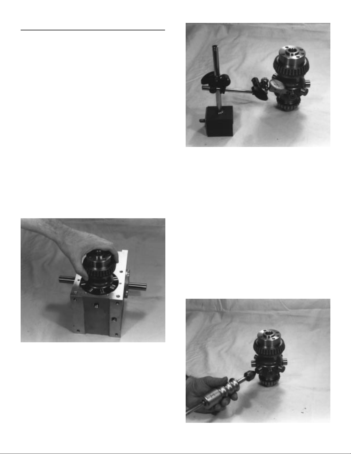
Fig.2 Inspecting Follower.
6. FOLLOWER REMOV AL.
A. Remove the setscrews. Apply heat to the
setscrews holding the follower studs and
remove while still warm.
B. Threaded holes have been provided in the
ends of the follower for ease of removal.
Use a slide hammer or a simple self made
pull tool. The slide made pull tool consists
of a short piece of round tubing large
enough to clear the follower diameter and a
small flat bar with a clearance hole large
enough to insert a capscrew of equal thread
size as the follower pull hole. Slip the tube
over the follower, place the bar over the tube
and thread a capscrew into the follower
tightening the capscrew will remove the
follower.
Fig.1 Removing output shaft.
5. INSPECTION OF CAM FOLLOWERS.
Inspect followers for damage or radial looseness. It
should not exceed .001 inch. Do not confuse radial
looseness with axial endplay . Endplay will be from
.03 to .06 as a normal condition. If it exceeds .06 it
may require replacement.
NOTE: Generally , followers are replaced as added
insurance against eventual failure.
3
Fig.3 Removing follower
Page 5

7. Check the follower holes for roundness. These
holes may be worn out due to overloads. The
holes should be round within .0005 to permit
reuse of the follower wheel.
8. REMOV AL OF BEARINGS.
A. Remove the large output bearing cone from
the output shaft with a small diameter
aluminum bar and a hammer. Place the bar
against the protruding edge of the cone and
tap with the hammer, working around the
perimeter to prevent binding. Continue this
until the cone is free of the shaft.
Fig.4 Removing bearing cone.
B. Remove the output bearing cups from the
cartridges and housing with puller, by prying
or by drilling and tapping for jack screws.
9. INPUT SHAFT / CAM REMOVAL.
NOTE: The output shaft must be removed prior to input
shaft removal.
A. Rotate the input shaft and inspect all parts
for wear or damage. Endplay in the input
shaft is not permissible.
B. Match mark all input cartridges relative to
the housing. These must be reinstalled in
the same side and position since they are
eccentric.
C. Remove all input bearing cartridge
capscrews.
D. Tap on the end of the input shaft to drive the
opposite cartridge from the housing. Then
drive the shaft in the opposite direction for
removal of other cartridge.
NOTE: Keep shims with their respective cartridges. You
will be asked to reinstall or replace with same shim
thickness during assembly .
E. Use a wheel puller to remove the bearing
cones from the input shaft.
F. Remove the cam locknuts with a spanner
wrench, if applicable. Be sure to bend the
washer locking tang away from the nut prior
to removal.
G. Press the shaft through the hole previously
occupied by the input cartridge (removed in
Step D). This will automatically remove the
cam from the input shaft. The use of an
arbor press is recommended but this
procedure can be accomplished by driving
the shaft through with a soft faced hammer.
Fig. 5 Pressing out shaft.
H. Remove cam through the access opening.
10. Remove the input bearing cups from the
cartridges with a pulley puller, by prying or by
drilling and tapping for jack screws.
ASSEMBLY
PRIOR TO REASSEMBLY
Clean and deburr all parts before reassembling
Follow tightening torque and Loctite™
recommendations as outlined in the “General
Service Manual”.
1. Use an arbor to press the bearing cups into the
cartridges. Coat the outside of the cup and the
bore of the cartridge with an anti-seize lubricant
prior to pressing. Fill cavity of cartridges with
bearing grease recommended in the “General
Service Manual”.
2. ASSEMBLING INPUT SHAFT.
NOTE: Assembly of the cam and bearings to the input
shaft must be done inside the housing.
A. Use arbor to press the cam onto shaft. Be
sure key is installed into shaft first. Apply
anti-sieze lubricant to shaft and bore prior to
pressing. The bore of the cam should be
heated prior to pressing, if a heat gun is
available.
B. Use a spanner wrench to install the cam
locknuts. Adjust nuts to center cam on shaft
( if applicable).
4
Page 6

C. Use an arbor to press bearing cones onto
shaft. Coat shaft and bearing bore with antisieze lubricant prior to pressing. The bore
of the bearing should be heated prior to
pressing, if a heat gun is available.
D. Install the input cartridges. Be sure to install
the same exact shims or equivalent height
as was removed in disassembly Step 1 1D.
E. Line up match marks.
F. Tighten cartridge mounting screws.
G. If endplay exists remove an equal amount of
shims from each side until there is a small
amount of drag from preloading the
bearings. In rare instances it may be
necessary to remachine the cartridges if all
shims have been removed and endplay still
exists.
H. Loosen input cartridge screws and rotate
the cartridge top to the most rearward
position attainable within the slots provided
in the cartridge.
3. ASSEMBLING OUTPUT SHAFT.
A. Install the bearings cones on the output
shaft. Coat the bore of the cone with an antisieze lubricant prior to installation. Tap in
place.
B. Install new followers with an arbor press.
C. Install the setscrews. The cone point
setscrews lock into the “V” notch. The cup
point setscrews lock against the flat. The
oval point setscrews are used when only
one flat is provided on the follower stud. Be
sure to use Loctite thread locking liquid as
recommended in the “General Service
Manual”.
D. Use an arbor to press the bearing cup into
the housing. Coat the outside of the cup and
the bore of the housing with an anti-sieze
lubricant prior to pressing.
E. Insert the output shaft/follower wheel
assembly into the housing.
F. Install the output cartridge with the
equivalent shim thickness removed in
disassembly .
G. Tighten cartridge mounting screws.
H. If endplay exists, remove shims until there is
a small amount of drag from preloading the
bearings. In rare instances it may be
necessary to remachine the cartridges if all
shims have been removed and endplay still
exists.
CAUTION: Be sure to press the followers in straight
as damage to the follower and wheel could occur if
improperly aligned during installation. Be sure that
the notches are aligned with the setscrew holes.
Fig.6 Installing new followers.
5
Page 7

4. SETTING CAM.
CAUTION: This mechanism is designed to operate
with adjacent followers in close contact along their
entire width with the surface of the cam during the
dwell period. Unless this condition is achieved by
proper installation, the mechanism will not transmit
its rated load, and furthermore, serious damage to
the cam and output shaft will occur .
A. Place the cam in dwell (keyway facing
rearward).
B. Rotate the tops of both input cartridges
toward the output until the cam followers
touch the cam.
C. Shift the cam axially until two adjacent
followers are in full contact with the cam rib.
(This will also require adjustment of the
eccentric input cartridges along with axial
adjustment of the cam.)
1) If there is a gap at the root of the
follower the cam should be shifted
toward the follower.
2) If there is a gap at the tip of the follower
the cam should be shifted away from the
follower.
Fig.8 Centering cam
D. Apply “Prussian Blue” to entire cam track.
E. Rotate the camshaft slowly with a small
handcrank to ensure that:
1) Both rollers are in contact with the cam
rib in dwell. Look for uniform bluing
pattern.
2) The follower is free at the center of the
crossover track.
3) You do not encounter unusual
resistance in motion. The bluing pattern
should be fairly uniform from side to side
during motion. If a patch of bluing id
worn off the side of the cam rib on one
side of the cam and not the other, shift
the cam a .002 to .005 inches in the
direction of the worn side. Do not
overshift the cam or knocking will occur.
4) The cam bluing should never be worn
off the leading or exit edges of the cam
ribs. If so this is an indication that the
cam is not adjusted properly.
5) There should be no looseness in any
dwell. If there is adjust the eccentric
input cartridges to slightly preload the
loosest dwell.
F. Tighten the locknuts and secure with Loctite
#242 as specified in the “General Service
Manual”. If lockwashers are used on your
model, bend the tangs over the nut to insure
locking.
G. Tighten the input cartridge capscrews and
dowel the cartridges to the housing.
H. Double check for endplay in output shaft.
Endplay is not permissible in the output
shaft.
5. Reinstall the access cover with a new
gasket. To insure leakage it is
recommended you also apply “General
Electric Silicone Rubber RTV -6” to the
housing and cover. CAUTION: If your
access cover is plexiglass be sure not to
over tighten or cracking will result.
6. Grease pack the main output bearing
with lubricant specified in the “General
Service Manual”.
7. Install new oil seals as described in the
“General Service Manual”.
8. Fill the index with the recommended oil
to level indicator. See “General Service
Manual”. Too high an oil level will cause
no damage. Too low a level may result in
unit failure.
6
Page 8

HOW TO ORDER P ARTS
Please refer to parts list shown in this manual. This parts list is for a standard Index Drive. If you feel your drive
is nonstandard or you are in doubt you should contact CAMCO Customer Service at (847) 459-5200 and
request a Bill of Materials for your specific unit based on serial number. CAMCO maintains records on all units
for a period of ten years.
You may order parts per the standard Bill of Material even if your unit is nonstandard. CAMCO’s order entry
people will review the closed order file based on the following information and supply you with the correct part.
REQUIRED INFORMATION
1. Original purchase order number (if available)
2. Customer name (original purchaser of drive)
3. Model number (location on name plate)
4. Serial number (location on name plate)
5. Approximate date of purchase.
TO ORDER PARTS contact CAMCO “Order Entry Department” Wheeling, Illinois
Phone (847) 459-5200 or Fax (847) 459-3064
A. Describe the parts required and the 14 digit part number as listed in the Standard Bill of Materials or a
Special Bill of Materials pertaining to your unit. State in you are using a Standard or Specific bill of
material.
B. Give as much of the above required information as possible.
ON WARRANTY
Replacement parts CAMCO will send freight prepaid via most practical means.
CAMCO will issue a “Returned Material Authorization Number” (RMA#) for the return of defective parts for
inspection. CAMCO will bill customer for repair parts. When inspection of returned parts has been completed
and determined to be a warranty problem, CAMCO will issue a credit to the customer for the repair parts and
freight charges.
ON NON-WARRANTY
Replacement or spare parts, with approved credit, are F.O.B. our plant Wheeling, Illinois.
7
Page 9

350RGD/RGS, 500RGD/RGS & 600RGD/RGS
8
Page 10

PARTS LIST FOR 350RGD INDEX DRIVE (STANDARD CONFIGURE)
ITEM NO. PART NUMBER DESCRIPTION
1 ......................................................48D43074001002 HOUSING
2......................................................48B43059007002INPUT SHAFT DBL EXT (W/O REDUCER)
........................................................48B43059007002INPUT SHAFT DBL EXT (W/R180 RED)
........................................................48C63670007002INPUT SHAFT DBL EXT (W/R225 RED)
3 ......................................................48C42987014006 OUTPUT SHAFT FOLL WHL 6 HOLE 3/4 FOLL
........................................................48C42987024008 OUTPUT SHAFT FOLL WHL 8 HOLE 3/4 FOLL
........................................................48C42987034010 OUTPUT SHAFT FOLL WHL 10 HOLE 5/8 FOLL
........................................................48C42987044012 OUTPUT SHAFT FOLL WHL 12 HOLE 5/8 FOLL
4 ...................................................... CAM. SPECIFY NUMBER OF STOPS AND INDEX TIME
........................................................
5 ......................................................48B43056003021 CARTRIDGE, UPPER OUTPUT
6 ......................................................26B01048003122 CARTRIDGE, ECCENTRIC INPUT (387P)
7 ......................................................48B30138009600 ACCESS COVER
8*.....................................................48B30139008700 GASKET, ACCESS COVER
9*.....................................................84D07329420000 OIL SEAL C/R 24954
10*...................................................48B06081018800 SHIM .002 THK
*.......................................................48B06081028800 SHIM .005 THK
*.......................................................48B06081038800 SHIM .010 THK
11*...................................................86D07328530022 BEARING CUP L610510
12*...................................................86D07328530021 BEARING CONE L610549
13 .................................................... NOT USED ON 350RGD OR 350RGS
14*...................................................86D07328300021 BEARING CONE 13687
15*...................................................86D07328300022 BEARING CUP 13621
16 ....................................................95A33001010000 SIGHT GLASS
17 ....................................................95A33002060000 DRAIN PLUG
18 .................................................... NOT USED ON 350RGD OR 350RGS
19 ....................................................48A43078009000 SPACER, CAM
20*...................................................86D07328170021 BEARING CONE 07100
21*...................................................86D07328170022 BEARING CUP 07196
22*...................................................26B01052008800 SHIM SET, INPUT (387P)
23 ....................................................95A08089000000 SPECIAL LARGE HEAD CAPSCREW
24*...................................................84D07329130000 OIL SEAL C/R 9838
25*...................................................84D07329330000 OIL SEAL 13739
26 ....................................................95A26003090000 BHCS 8-32 X 3/8
27 ....................................................031K194 KEY 5/16 SQ. X 1 15/16 LARGE
28 ....................................................95A33000010000 AIR VENT (BREATHER)
29 ....................................................95A26012070000 SSS OVL PT 10-24 X 3/8
30 ...................................................82C33150020003FOLLOWER 3/4 DIA
........................................................82C33150010003 FOLLOWER 5/8 DIA
31 ....................................................95A26000380000 SHCS 1/4-20 X 1/2
32* ...................................................48A06080018800 SHIM .002 THK, LOWER OUTPUT
* .....................................................48A06080028800 SHIM .005 THK, LOWER OUTPUT
* .....................................................48A06080038800 SHIM .010 THK, LOWER OUTPUT
33 ....................................................48B44707003002 CARTRIDGE, LOWER OUTPUT
* Indicates parts supplies with Spare Parts Kit #350RGD SPK
(CONTACT CAMCO FOR ASSIST ANCE IN CAM SELECTION)
9
Page 11

PARTS LIST FOR 350RGS INDEX DRIVE (STANDARD CONFIGURATION)
ITEM NO. PART NUMBER DESCRIPTION
1 ......................................................48D43074001002 HOUSING
2 ......................................................48B43059007002 INPUT SHAFT DBL EXT (W/O REDUCER)
........................................................48B43059007002INPUT SHAFT DBL EXT (W/R180 RED)
........................................................48C63670007002INPUT SHAFT DBL EXT (W/R225 RED)
3 ......................................................48C42996014006 OUTPUT SHAFT SGL EXT 6 HOLE 3/4 FOLL
........................................................48C42996024008 OUTPUT SHAFT SGL EXT 8 HOLE 3/4 FOLL
........................................................48C42996034010 OUTPUT SHAFT SGL EXT 10 HOLE 5/8 FOLL
........................................................48C42996044012 OUTPUT SHAFT SGL EXT 12 HOLE 5/8 FOLL
........................................................48C42998014006 OUTPUT SHAFT DBL EXT 6 HOLE 3/4 FOLL
........................................................48C42998024008 OUTPUT SHAFT DBL EXT 8 HOLE 3/4 FOLL
........................................................48C42998034010 OUTPUT SHAFT DBL EXT 10 HOLE 5/8 FOLL
........................................................48C42998044012 OUTPUT SHAFT DBL EXT 12 HOLE 5/8 FOLL
4 ...................................................... CAM, SPECIFY NUMBER OF STOPS AND INDEX TIME.
........................................................
5 ......................................................48B43056003021 CARTRIDGE, UPPER OUTPUT
6 ......................................................26B01048003122 CARTRIDGE, ECCENTRIC INPUT (387P)
7 ......................................................48B30138009600 ACCESS COVER
8*.....................................................48B30139008700 GASKET, ACCESS COVER
9*.....................................................84D07329420000 OIL SEAL C/R 24954
10*...................................................48B06081018800 SHIM .002 THK
*.......................................................48B06081028800 SHIM .005 THK
*.......................................................48B06081038800 SHIM .010 THK
11*...................................................86D07328530022 BEARING CUP L610510
12*...................................................86D07328530021 BEARING CONE L610549
13 ....................................................---------- NOT USED ON 350RGD OR 350RGS
14*...................................................86D07328300021 BEARING CONE 13687
15*...................................................86D07328300022 BEARING CUP 13621
16 ....................................................95A33001010000 SIGHT GLASS
17 ....................................................95A33002060000 DRAIN PLUG
18 ....................................................---------- NOT USED ON 350RGD OR 350RGS
19 ....................................................48A43078009000 SPACER, CAM
20*...................................................86D07328170021 BEARING CONE 07100
21*...................................................86D07328170022 BEARING CUP 07196
22*...................................................26B01052008800 SHIM SET, INPUT (387P)
23 ....................................................95A08089000000 SPECIAL LARGE HEAD CAPSCREW
24*...................................................84D07329130000 OIL SEAL C/R 9838
25*...................................................84D07329330000 OIL SEAL 13739
26 ....................................................95A26003090000 BHCS 8-32 X 3/8
27 ....................................................031K194 KEY 5/16 SQ. X 1 15/16 LARGE
28 ....................................................95A33000010000 AIR VENT (BREATHER)
29 ....................................................95A26012070000 SSS OVL PT 10-24 X 3/8
30 ...................................................82C33150020003FOLLOWER 3/4 DIA
........................................................82C33150010003 FOLLOWER 5/8 DIA
31 ....................................................95A26000380000 SHCS1/4-20 X 1/2
32*....................................................48A06080018800 SHIM .002 THK
*......................................................48A06080028800 SHIM .005 THK
*......................................................48A06080038800 SHIM .010 THK
33 ....................................................48B44707003002 CARTRIDGE, LOWER OUTPUT
* Indicates parts supplied with Spare Parts Kit #350RGS SPK
(CONT ACT CAMCO FOR ASSISTANCE IN CAM SELECTION)
10
Page 12

PARTS LIST FOR 500RGD INDEX DRIVE (STANDARD CONFIGURATION)
ITEM NO. PART NUMBER DESCRIPTION
1 ......................................................50D42543001002 HOUSING
2 ......................................................50C42559007002 INPUT SHAFT DBL EXT (W/O REDUCER)
........................................................50C64220007002INPUT SHAFT DBL EXT (W/225/R260 RED)
........................................................50C42559007002 INPUT SHAFT DBL EXT (W/3” CONE RED)
3 ......................................................50D42933014006 OUTPUT SHAFT FOLL 6 HOLE 1 1/4” FOLL
........................................................50D42933014008 OUTPUT SHAFT FOLL 8 HOLE 1 1/4” FOLL
........................................................50D42933014010 OUTPUT SHAFT FOLL 10 HOLE 1” FOLL
........................................................50D42933014012 OUTPUT SHAFT FOLL 12 HOLE 7/8” FOLL
4 ...................................................... CAM, SPECIFY NUMBER OF STOPS AND
........................................................ INDEX TIME. (CONTACT CAMCO FOR
........................................................ ASSISTANCE IN CAM SELECTION)
5 ......................................................50C42554003002 CARTRIDGE, OUTPUT
6 ......................................................28K26335003022 CARTRIDGE, ECCENTRIC INPUT
7 ......................................................50B42578000000 ACCESS COVER
8*.....................................................50B42579000000 GASKET, ACCESS COVER
9*.....................................................84D07329660000 OIL SEAL C/R 42426
10*...................................................57B40958018800 SHIM .002 THK, UPPER OUTPUT
*.......................................................57B40958028800 SHIM .005 THK, UPPER OUTPUT
*.......................................................57B40958038800 SHIM .010 THK, UPPER OUTPUT
11*...................................................86D07328750022 BEARING CUP L521910
12*...................................................86D07328750021 BEARING CONE L521949
13 ....................................................95A33031540000 RETAINING RING 5100-225
14 ....................................................86D07328500021 BEARING CONE 3979
15 ....................................................86D07328500022 BEARING CUP 3920
16 ....................................................96A33001010000 SIGHT GLASS
17 ....................................................95A33002010000 DRAIN PLUG
18 ....................................................95A26010100000 LOCKWASHER W-10
19 ....................................................95A26009100000 LOCKNUT PN-10
20*...................................................86D07328360021 BEARING CONE 26885
21*...................................................86D07328280022 BEARING CUP 26822
22*...................................................28A02522018800 SHIM .002 THK, INPUT
*.......................................................28A02522028800 SHIM .005 THK, INPUT
*.......................................................28A02522038800 SHIM .010 THK, INPUT
23 ....................................................95A08089000000 SPECIAL LARGE HEAD CAPSCREW
24*...................................................84D07329290000 OIL SEAL C/R 16368
25*...................................................84D07329400000 OIL SEAL 22424
26 ....................................................95A26003150000 BHCS 10-24 X 1/2
27 ....................................................050K275 KEY 1/2 SQ. X 2 3/4 LARGE
28 ....................................................95A33000010000 AIR VENT (BREATHER)
29 ....................................................95A26012140000 SSS OVL PT 1/4-20 X 1/2
30 ...................................................82C33150030003FOLLOWER 7/8 DIA
........................................................82C33150040003 FOLLOWER 1” DIA
........................................................82A43724000000 FOLLOWER 1 1/4 DIA
31 ....................................................95A26000700000 SHCS 3/8-16 X 7/8
32* ...................................................50B45872018800 SHIM .002 THK, LOWER OUTPUT
* ....................................................50B45872028800 SHIM .005 THK, LOWER OUTPUT
* .....................................................50B45872038800 SHIM .010 THK, LOWER OUTPUT
33 .....................................................50B44805003002 CARTRIDGE, LOWER OUTPUT
* Indicates parts supplied with Spare Parts Kit #500RGD SPK
11
Page 13

PARTS LIST FOR 500RGS INDEX DRIVE (STANDARD CONFIGURATION)
ITEM NO. PART NUMBER
1 ......................................................50D42543001002 HOUSING
2 ......................................................50C42559007002 INPUT SHAFT DBL EXT (W/O REDUCER)
........................................................50C64220007002INPUT SHAFT DBL EXT (W/225/R260 RED)
........................................................50C42559007002 INPUT SHAFT DBL EXT (W/3” CONE RED)
3 ......................................................50D42935014006 OUTPUT SHAFT SGL EXT 6 HOLE 1 1/4” FOLL
........................................................50D42935014008 OUTPUT SHAFT SGL EXT 8 HOLE 1 1/4” FOLL
........................................................50D42935034010 OUTPUT SHAFT SGL EXT 10 HOLE 1” FOLL
........................................................50D42935044012 OUTPUT SHAFT SGL EXT 12 HOLE 7/8” FOLL
........................................................50D42936014006 OUTPUT SHAFT DBL EXT 6 HOLE 1 1/4” FOLL
........................................................50D42936024008 OUTPUT SHAFT DBL EXT 8 HOLE 1 1/4” FOLL
........................................................50D42936034010 OUTPUT SHAFT DBL EXT 10 HOLE 1” FOLL
........................................................50D42936044012 OUTPUT SHAFT DBL EXT 12 HOLE 7/8” FOLL
4 ...................................................... CAM, SPECIFY NUMBER OF STOPS ANDINDEX TIME.
........................................................
5 ......................................................50C42557003002 CARTRIDGE, OUTPUT
6 ......................................................28K26335003022 CARTRIDGE, ECCENTRIC INPUT
7 ......................................................50B42578000000 ACCESS COVER
8*.....................................................50B42579000000 GASKET , ACCESS COVER
9*.....................................................84D07329940000 OIL SEAL C/R 22424
10*...................................................57B40958018800 SHIM .002 THK, UPPER OUTPUT
*.......................................................57B40958028800 SHIM .005 THK, UPPER OUTPUT
*.......................................................57B40958038800 SHIM .010 THK
11*...................................................86D07328500022 BEARING CUP 3920
12*...................................................86D07328750021 BEARING CONE 3979
13 ....................................................95A33031540000 RETAINING RING 5100-225
14 ....................................................86D07328500021 BEARING CONE 3979
15 ....................................................86D07328500022 BEARING CUP 3920
16 ....................................................96A33001010000 SIGHT GLASS
17 ....................................................95A33002060000 DRAIN PLUG
18 ....................................................95A26010100000 LOCKWASHER W-10
19 ....................................................95A26009100000 LOCKNUT PN-10
20*...................................................86D07328360021 BEARING CONE 26885
21*...................................................86D07328280022 BEARING CUP 26822
22*...................................................28A02522018800 SHIM .002 THK
*.......................................................28A02522028800 SHIM .005 THK
*.......................................................28A02522038800 SHIM .010 THK
23 ....................................................95A08089000000 SPECIAL LARGE HEAD CAPSCREW
24*...................................................84D07329290000 OIL SEAL C/R 16368
25*...................................................84D07329400000 OIL SEAL 22424
26 ....................................................95A26003150000 BHCS 10-24 X 1/2
27 ....................................................050K275 KEY 1/2 SQ. X 2 3/4 LARGE
28 ....................................................95A33000010000 AIR VENT (BREATHER)
29 ....................................................95A26012140000 SSS OVL PT 1/4-20 X 1/2
30 ...................................................82C33150030003FOLLOWER 7/8 DIA
........................................................82C33150040003 FOLLOWER 1” DIA
........................................................82A43724000000 FOLLOWER 1 1/4 DIA
31 ....................................................95A26000700000 SHCS 3/8-16 X 7/8
32* ......................................................50B45872018800 SHIM .002 THK, LOWER OUTPUT
* ......................................................50B45872028800 SHIM .005 THK, LOWER OUTPUT
* ......................................................50B45872038800 SHIM .010 THK, LOWER OUTPUT
33 ........................................................50B44805003002 CARTRIDGE, LOWER OUTPUT
* Indicates parts supplied with Spare Parts Kit #500RGS SPK
12
DESCRIPTION
(CONT ACT CAMCO FOR ASSISTANCE IN CAM SELECTION)
Page 14

P AR TS LIST FOR 600RGD INDEX DRIVE (STANDARD CONFIGURATION)
ITEM NO. PART NUMBER DESCRIPTION
1 ......................................................53D45466001002 HOUSING
2 ......................................................53C45547007002 INPUT SHAFT DBL EXT (W/O REDUCER)
........................................................53C45548007002 INPUT SHAFT DBL EXT (W/3” CONE RED)
........................................................53C45549007002 INPUT SHAFT DBL EXT (W/3 1/2 RED)
3 ......................................................53D45531014006 OUTPUT SHAFT FOLL WHL 6 HOLE 1 1/2 FOLL
........................................................53D45531024008 OUTPUT SHAFT FOLL WHL 8 HOLE 1 1/4 FOLL
........................................................53D45531034010 OUTPUT SHAFT FOLL WHL 12 HOLE 1” FOLL
4 ...................................................... CAM, SPECIFY NUMBER OF STOPS AND
........................................................ INDEX TIME. (CONTACT CAMCO FOR
........................................................ ASSISTANCE IN CAM SP ACER SELECTION)
5 ......................................................53C2430703121 CARTRIDGE, OUTPUT
6 ......................................................53B45462003002 CARTRIDGE, ECCENTRIC INPUT
7 ......................................................53C24365009999 ACCESS COVER (OUTPUT END)
........................................................53C45469000000 ACCESS COVER (INPUT END)
8*.....................................................53C24369009999 GASKET, ACCESS COVER (OUTPUT END)
*.......................................................53C24370009999 GASKET, ACCESS COVER (OUTPUT END)
9*.....................................................84D07329760000 OIL SEAL C/R 57521
10*...................................................53A24372018800 SHIM .002 THK
*.......................................................53A24372028800 SHIM .005 THK
*.......................................................53A24372038800 SHIM .010 THK
11*...................................................86D07328830022 BEARING CUP 36620
12*...................................................86D07328830021 BEARING CONE 36690
13 ....................................................95A26000520000 SHCS 5/16-16 X 1/2
14 ....................................................86D07328700021 BEARING CONE JM716649
15 ....................................................86D07328700022 BEARING CUP JM716610
16 ....................................................95A33001010000 SIGHT GLASS
17 ....................................................95A33002060000 DRAIN PLUG
18 ....................................................95A26010100000 LOCKWASHER W-10
19 ....................................................95A26009100000 LOCKNUT PN-10
20*...................................................86D07328370021 BEARING CONE HM803145
21*...................................................86D07328370022 BEARING CUP HM803110
22*...................................................30B02669018800 SHIM .002 THK
*.......................................................30B02669028800 SHIM .005 THK
*.......................................................30B02669038800 SHIM .010 THK
23 ....................................................95A08116000000 SPECIAL LARGE HEAD CAPSCREW
24*...................................................84D07329270000 OIL SEAL C/R 15215
25*...................................................84D07329590000 OIL SEAL 32540
26 ....................................................95A26000280000 SHCS 10-24 X 1/2
27 ....................................................050K350 KEY 1/2 SQ. X 3 1/2 LONG
28 ....................................................95A33000010000 AIR VENT (BREATHER)
29 ....................................................95A26012170000 SSS OVL PT 1/4-20 X 3/4
........................................................95A26006290000 SSS CONE PT 5/16-18 X 3/4
30 ...................................................82C33150040003FOLLOWER 1” DIA
........................................................82C33150050003 FOLLOWER 1 1/4” DIA
........................................................82J24564000000 FOLLOWER 1 1/2” DIA (USE SSS 95A26006290000)
31 ....................................................95A26000700000 SHCS 3/8-16 X 7/8
32*...................................................53A45495018800 SHIM .002 THK.
........................................................53A45495028800 SHIM .005 THK.
........................................................53A45495038800 SHIM .010 THK.
33 ....................................................53C45479003002 CART, LOWER OUTPUT
* Indicates parts supplies with Spare Parts Kit #600RGD SPK
13
Page 15

PARTS LIST FOR 600RGS INDEX DRIVE (STANDARD CONFIGURATION)
ITEM NO. PART NUMBER DESCRIPTION
1 ......................................................53D45466001002 HOUSING
2 ......................................................53C45547007002 INPUT SHAFT DBL EXT (W/O REDUCER)
........................................................53C45548007002 INPUT SHAFT DBL EXT (W/3” CONE RED)
........................................................53C45549007002 INPUT SHAFT DBL EXT (W/3 1/2 RED)
3 ......................................................53D45531014006 OUTPUT SHAFT FOLL WHL 6 HOLE 1 1/2 FOLL SE
........................................................53D45531024008 OUTPUT SHAFT FOLL WHL 8 HOLE 1 1/4 FOLL SE
........................................................53D45531034012 OUTPUT SHAFT FOLL WHL 12 HOLE 1” FOLL SE
........................................................53D45532014006 OUTPUT SHAFT FOLL WHL 6 HOLE 1 1/2 FOLL DE
........................................................53D45532024008 OUTPUT SHAFT FOLL WHL 8 HOLE 1 1/4 FOLL DE
........................................................53D45532034012 OUTPUT SHAFT FOLL WHL 12 HOLE 1” FOLL DE
4 ...................................................... CAM, SPECIFY NUMBER OF STOPS AND INDEX TIME.
........................................................ (CONTACT CAMCO FOR ASSISTANCE IN CAM SPACER
........................................................ SELECTION)
5 ......................................................53C45534003002 CARTRIDGE, OUTPUT
6 ......................................................53B45462003002 CARTRIDGE, ECCENTRIC INPUT
7 ......................................................53C24365009999 ACCESS COVER (OUTPUT END)
........................................................53C45469000000 ACCESS COVER (INPUT END)
8*.....................................................53C24369009999 GASKET, ACCESS COVER (OUTPUT END)
*.......................................................53C24370009999 GASKET, ACCESS COVER (OUTPUT END)
9*.....................................................84D07329590000 OIL SEAL C/R 32540
10*...................................................53A24372018800 SHIM .002 THK
*.......................................................53A24372028800 SHIM .005 THK
*.......................................................53A24372028800 SHIM .010 THK
11*...................................................86D07328700022 BEARING CUP JM716610
12*...................................................86D07328700021 BEARING CONE JM716649
13 ....................................................95A26000520000 SSS53/16-16 X 1/2
14 ....................................................86D07328700021 BEARING CONE JM716649
15 ....................................................86D07328700022 BEARING CUP JM716610
16 ....................................................95A33001010000 SIGHT GLASS
17 ....................................................95A33002060000 DRAIN PLUG
18 ....................................................95A26010100000 LOCKWASHER W-10
19 ....................................................95A26009100000 LOCKNUT PN-10
20*...................................................86D07328370021 BEARING CONE HM803145
21*...................................................86D07328370022 BEARING CUP HM803110
22*...................................................30B02669018800 SHIM .002 THK
*.......................................................30B02669028800 SHIM .005 THK
*.......................................................30B02669038800 SHIM .010 THK
23 ....................................................95A08116000000 SPECIAL LARGE HEAD CAPSCREW
24*...................................................84D07329270000 OIL SEAL C/R 15215
25*...................................................84D07329590000 OIL SEAL 32540
26 ....................................................95A26000280000 SHCS 10-24 X 1/2
27 ....................................................050K350 KEY 1/2 SQ. X 3 1/2 LONG
28 ....................................................95A33000010000 AIR VENT (BREATHER)
29 ....................................................95A26012170000 SSS OVL PT 1/4-20 X 3/4
........................................................95A26006290000 SSS CONE PT 5/16-18 X 3/4
30 ...................................................82C33150040003FOLLOWER 1” DIA
........................................................82C33150050003 FOLLOWER 1 1/4” DIA
........................................................82J24564000000 FOLLOWER 1 1/2” DIA (USE SSS 95A26006290000)
31 ....................................................95A26000700000 SHCS 3/8-16 X 7/8
32*...................................................53A45495018800 SHIM .002 THK.
........................................................53A45495028800 SHIM .005 THK.
........................................................53A45495038800 SHIM .010 THK.
33 ....................................................53C45479003002 CART, LOWER OUTPUT
* Indicates parts supplies with Spare Parts Kit #600RGS SPK
14
Page 16

CAMCO & FERGUSON Products
1444 South Wolf Road
Wheeling, IL 60090
USA
ph: 847-459-5200
toll-free: 800-645-5200
fax: 847-459-3064
camco@destaco.com
www.camcoindex.com
ISO 9001:2000 Registered
DE-STA-CO Headquarters
Auburn Hills, Michigan USA
248-836-6700
marketing@destaco.com
www.destaco.com
DE-STA-CO Europe
Germany
+49-6171-705-0
europe@destaco.com
DE-STA-CO Asia
Thailand
+66-2-326-0812
info@destaco.com
DE-STA-CO South America
Brazil
0800-124070
samerica@destaco.com
© DE-STA-CO 2004-2010
All rights reserved
Printed in U.S.A.
SKU 0063 REV. 05/2010
 Loading...