

Page 1

RFD OVEN SERIES WITH
PROTOCOL 3
TM
CONTROLLER
OWNER’S MANUAL
C-250
PN 320253
VERSION 1
11/2012
Page 2

PREFACE RFD Oven Series Owner’s Manual
Revision
Date
Author
Description
1
11/2012
Livingston
Format changes and revised for Protocol 3.
2 Version 1
Revision History
All rights reserved. No part of the contents of this manual may be reproduced, copied or transmitted in any form or by any
means including graphic, electronic, or mechanical methods or photocopying, recording, or information storage and
retrieval systems without the written permission of Despatch Industries, unless for purchaser's personal use.
Copyright © 2012 by Despatch Industries.
Page 3

RFD Oven Series Owner’s Manual PREFACE
Version 1 3
Table of Contents
1. About This Manual ............................................................................................................. 6
1.1. Important User Information ..................................................................................... 6
1.2. Manufacturer & Service .......................................................................................... 7
1.3. Organization of this Manual .................................................................................... 7
1.4. Conventions ............................................................................................................. 8
1.5. Specifications .......................................................................................................... 8
1.5.1. Dimensions .............................................................................................................. 8
1.5.2. Capacities ................................................................................................................ 9
1.5.3. Temperatures ......................................................................................................... 10
1.5.4. Power ..................................................................................................................... 11
1.5.5. Capability .............................................................................................................. 12
2. Safety ................................................................................................................................ 13
2.1. Safety Information ................................................................................................. 13
2.1.1. Lockout .................................................................................................................. 13
2.1.1.1. Lockout Requirements ................................................................................... 13
2.1.1.2. Lockout Procedure ......................................................................................... 13
2.2. Maintenance .......................................................................................................... 14
2.3. Electrical Power ..................................................................................................... 14
2.4. Fire ......................................................................................................................... 14
2.5. Equipment Lockout Requirements ........................................................................ 14
2.5.1. Optional Disconnect Switch .................................................................................. 15
3. Theory of Operation ......................................................................................................... 16
3.1. The RFD Oven Series ............................................................................................ 16
3.2. Damper Control ..................................................................................................... 17
3.2.1. Determining Damper Settings ............................................................................... 18
3.2.1.1. Fresh Air Damper Fully Closed Position ...................................................... 18
3.2.1.2. Fresh Air Damper Fully Open Position ......................................................... 18
3.2.1.3. Exhaust Damper Control ............................................................................... 18
3.3. Optional Adjustable Louvers ................................................................................. 19
3.3.1. Purpose of Adjustable Airflow .............................................................................. 20
3.3.2. Supply Air Adjustment .......................................................................................... 20
3.3.3. Return Air Adjustment .......................................................................................... 20
3.4. The Protocol 3 Controller ...................................................................................... 20
3.5. Optional High Limit Audible Alarm ..................................................................... 22
3.6. Purge Timer ........................................................................................................... 22
3.7. Airflow Interlocking Safety Switch ....................................................................... 22
4. Assembly & Setup ............................................................................................................ 23
4.1. Unpack & Inspect The RFD Oven ........................................................................ 23
4.1.1. If Damaged During Shipping ................................................................................ 23
4.2. Set up The RFD Oven ........................................................................................... 23
4.2.1. Select Oven Location ............................................................................................ 23
4.2.1.1. Placement Requirements ............................................................................... 24
4.3. Exhaust Connections ............................................................................................. 24
4.4. Wiring & Power Connections ............................................................................... 25
5. Operation .......................................................................................................................... 26
5.1. Load Oven ............................................................................................................. 26
5.2. Pre-Startup Checklist ............................................................................................. 27
5.3. Operating Procedure .............................................................................................. 28
All rights reserved. No part of the contents of this manual may be reproduced, copied or transmitted in any form or by any
Copyright © 2012 by Despatch Industries.
means including graphic, electronic, or mechanical methods or photocopying, recording, or information storage and
retrieval systems without the written permission of Despatch Industries, unless for purchaser's personal use.
Page 4

PREFACE RFD Oven Series Owner’s Manual
4 Version 1
5.3.1. Check Fan Rotation and Other Preliminaries ........................................................ 28
5.3.2. Start and Operate the Oven ................................................................................... 29
5.3.3. Shutdown ............................................................................................................... 29
5.3.4. Working with Protocol 3 Operating Modes .......................................................... 30
6. Maintenance ..................................................................................................................... 31
6.1. Checklist ................................................................................................................ 31
6.2. Maintenance Schedule ........................................................................................... 32
6.3. Check Fans ............................................................................................................ 33
6.4. Test Purge Timer ................................................................................................... 33
6.5. Test Airflow Switch .............................................................................................. 33
6.5.1. To Set or Adjust Airflow Switch ........................................................................... 33
6.5.2. Example: Verify Exhaust Fan Airflow Switch Setpoint........................................ 33
6.6. Lubrication ............................................................................................................ 35
6.7. Check Safety Controls ........................................................................................... 35
6.8. Check High-Limit Controller ................................................................................ 35
6.9. Replacement Parts ................................................................................................. 36
6.10. Repairs ................................................................................................................... 36
6.10.1. Protocol 3 Controller .................................................................................... 36
7. Troubleshooting................................................................................................................ 37
7.1. Troubleshooting: Possible Problems and Solutions .............................................. 37
7.2. Troubleshoot Airflow Conditions .......................................................................... 38
7.3. Troubleshooting: Error Messages and Alarm ........................................................ 39
8. Appendices ....................................................................................................................... 40
8.1. Standard Products Warranty .................................................................................. 40
8.2. MRC5000 Setup (Optional) .................................................................................. 41
8.3. Electrical Schematics ............................................................................................. 41
Figures
Figure 1. Design Information and Specification Label. ................................................................ 10
Figure 2. Electrical Specification Label. ....................................................................................... 11
Figure 3. Disconnect Switch.......................................................................................................... 15
Figure 4. RFD Oven Series. .......................................................................................................... 16
Figure 5. RFD Fresh Air Damper Control. .................................................................................... 17
Figure 6. RFD Exhaust Damper Control. ...................................................................................... 17
Figure 7. Standard perforated panels and adjustable louvers. ....................................................... 19
Figure 8. Initial factory settings for optional louvers. ................................................................... 19
Figure 9. Protocol 3 Operator Interface. ........................................................................................ 21
Figure 10. The Purge timer red light is illuminated during the timing period. .............................. 22
Figure 11. Airflow interlocking safety switch. .............................................................................. 22
Figure 12. RFD Forced Exhaust Assembly. .................................................................................. 24
Figure 13. Power, Heat and Alarm Silence Switches. ................................................................... 28
Figure 14. Minimum purge time is listed on the RFD oven design specification label. ............... 28
Figure 15. Airflow Switch Indicator. ............................................................................................ 34
Figure 16. Adjust the airflow switch. ............................................................................................ 35
Figure 17. RFD2-13-2E, 208V (Drawing 320219-01). ................................................................. 42
Figure 18. RFD2-13-2E, 208V (Drawing 320219-02). ................................................................. 42
Figure 19. RFD2-13-2E, 240V (Drawing 320221-01). ................................................................. 42
Figure 20. RFD2-13-2E, 240V (Drawing 320221-02). ................................................................. 42
Copyright © 2012 by Despatch Industries.
All rights reserved. No part of the contents of this manual may be reproduced, copied or transmitted in any form or by any
means including graphic, electronic, or mechanical methods or photocopying, recording, or information storage and
retrieval systems without the written permission of Despatch Industries, unless for purchaser's personal use.
Page 5

RFD Oven Series Owner’s Manual PREFACE
Version 1 5
Figure 21. RFD2-13-2E, 480V (Drawing 320223-01). ................................................................. 42
Figure 22. RFD2-13-2E, 480V (Drawing 320223-02). ................................................................. 42
Figure 23. RFD2-13-2E Oven Assembly (Drawing 148457-01). ................................................. 42
Figure 24. RFD2-19-2E, 208V (Drawing 320228-01). ................................................................. 42
Figure 25. RFD2-19-2E, 208V (Drawing 320228-02). ................................................................. 42
Figure 26. RFD2-19-2E, 240V (Drawing 320230-01). ................................................................. 42
Figure 27. RFD2-19-2E, 240V (Drawing 320230-02). ................................................................. 42
Figure 28. RFD2-19-2E, 480V (Drawing 320232-01). ................................................................. 42
Figure 29. RFD2-19-2E, 480V (Drawing 320232-02). ................................................................. 42
Figure 30. RAD2-19-2E Oven Assembly (Drawing 162533-01). ................................................. 42
Figure 31. RFD2-35-2E, 208V (Drawing 320237-01). ................................................................. 42
Figure 32. RFD2-35-2E. 208V (Drawing 320237-02). ................................................................. 42
Figure 33. RFD2-35-2E, 240V (Drawing 320239-01). ................................................................. 42
Figure 34. RFD2-35-2E, 240V (Drawing 320239-02). ................................................................. 42
Figure 35. RFD2-35-2E, 480V (Drawing 320241-01). ................................................................. 42
Figure 36. RFD2-35-2E, 480V (Drawing 320241-02). ................................................................. 42
Figure 37. RFD2-35-2E Oven Assembly (Drawing 148439-01). ................................................. 42
Tables
Table 1. Damper Positions for Chamber Pressure. ........................................................................ 17
Table 2. Purge timer settings for various RFD models. ................................................................ 22
Table 3. Troubleshooting grid. ...................................................................................................... 37
Table 4. Airflow Troubleshooting. ................................................................................................ 38
Table 5. Error Messages and Next Steps. ...................................................................................... 39
Table 6. MRC 5000 Settings. ........................................................................................................ 41
All rights reserved. No part of the contents of this manual may be reproduced, copied or transmitted in any form or by any
Copyright © 2012 by Despatch Industries.
means including graphic, electronic, or mechanical methods or photocopying, recording, or information storage and
retrieval systems without the written permission of Despatch Industries, unless for purchaser's personal use.
Page 6

ABOUT THIS MANUAL RFD Oven Series Owner’s Manual
Before operating this equipment, carefully read instruction
manual.
Values displayed on screens are examples only. Though
those values may be typical, contact Despatch Industries for
the final value.
Users of this equipment must comply with operating
procedures and training of operation personnel as required
by the Occupational Safety and Health Act (OSHA) of 1970,
Section 5 and relevant safety standards, as well as other
safety rules and regulations of state and local governments.
Refer to the relevant safety standards in OSHA and National
Fire Protection Association (NFPA), section 86 of 1985.
6 Version 1
1. About This Manual
1.1. Important User Information
Copyright © 2012 by Despatch Industries.
All rights reserved. No part of the contents of this manual may be reproduced, copied, or
transmitted in any form or by any means including graphic, electronic, or mechanical methods or
photocopying, recording, or information storage and retrieval systems without the written
permission of the publisher, unless it is for the purchaser's personal use.
Printed and bound in the United States of America.
The information in this manual is subject to change without notice and does not represent a
commitment on the part of Despatch Industries. Despatch Industries does not assume any
responsibility for any errors that may appear in this manual.
In no event will Despatch Industries be liable for technical or editorial omissions made herein,
nor for direct, indirect, special, incidental, or consequential damages resulting from the use or
defect of this manual.
All rights reserved. No part of the contents of this manual may be reproduced, copied or transmitted in any form or by any
means including graphic, electronic, or mechanical methods or photocopying, recording, or information storage and
retrieval systems without the written permission of Despatch Industries, unless for purchaser's personal use.
Copyright © 2012 by Despatch Industries.
Page 7
RFD Oven Series Owner’s Manual ABOUT THIS MANUAL
Danger!
Only fully-trained and qualified personnel should setup and
maintain this equipment. Improper setup and operation of this
equipment could cause an explosion that may result in
equipment damage, personal injury or possible death.
Global Headquarters
Contact
Service & Technical
Support
Despatch Industries
8860 207th Street
Lakeville, MN 55044
USA
International/Main: 1-952-469-5424
US toll free: 1-888-337-7282
Fax: 1-952-469-4513
info@despatch.com
www.despatch.com
Service: 1-952-469-8230
US toll free: 1-800-473-7373
Service @despatch.com
Version 1 7
The information in this document is not intended to cover all possible conditions and situations
that might occur. The end user must exercise caution and common sense when installing or
maintaining Despatch Industries products. If any questions or problems arise, call Despatch
Industries at 1-888-DESPATCH or 1-952-469-5424.
1.2. Manufacturer & Service
The RFD oven series, which includes RFD2-13, RFD2-19 and RFD2-35, is manufactured by
Despatch Industries.
Despatch has specialized in thermal processing for over 100 years. Technical expertise gained
over those years helps provide innovative solutions to critical applications in vertical markets and
cutting edge technology worldwide. Despatch products are backed by a drive for long-term
customer satisfaction and a strong sense of responsibility. The worldwide network of factorytrained Service Professionals is available to support your Despatch equipment. From full service
preventive maintenance to routine repair and certified calibration and uniformity, the Despatch
service network is positioned to respond to your business needs. Our service programs are
customized to meet your specific needs using our Advantage Service Assurance Program
(ASAP). For more information on ASAP, visit www.despatch.com.
1.3. Organization of this Manual
This owner’s manual contains the most comprehensive set of information for the Despatch RFD
oven series, including installation instructions, theory of operation, and operating instructions,
among other things. To save time and expense in case of trouble, it is urged that the operators
search this manual for helpful suggestions before requesting factory assistance.
All rights reserved. No part of the contents of this manual may be reproduced, copied or transmitted in any form or by any
means including graphic, electronic, or mechanical methods or photocopying, recording, or information storage and
retrieval systems without the written permission of Despatch Industries, unless for purchaser's personal use.
Copyright © 2012 by Despatch Industries.
Page 8
ABOUT THIS MANUAL RFD Oven Series Owner’s Manual
Danger!
Failure to heed warnings in this instruction manual and on the
oven could result in personal injury, property damage or death.
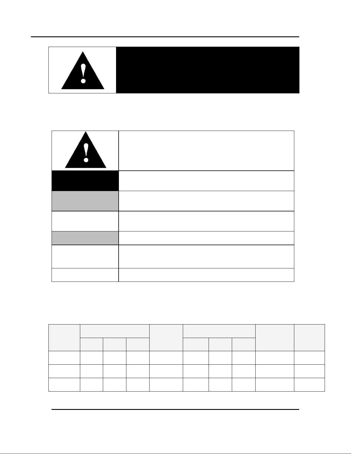
This icon signifies information that describes an unsafe
condition that may result in death, serious injury, or damage
to the equipment.
Danger!
Danger is the signal word used to indicate a hazardous
situation that, if not avoided, will result in death or severe
injury.
Warning!
Warning is the signal word used to indicate a hazardous
situation that, if not avoided, could result in death or severe
injury.
Caution!
Caution is the signal word used to indicate a hazardous
situation that, if not avoided, could result in moderate or
minor injury.
Notice
Notice is the signal word used to indicate a hazardous
situation that, if not avoided, could result in property damage.
This icon signifies supplemental important information.
LOG OUT
Bold, 10 point sans-serif typeface indicates a specific key or
button on screen to click.
Models
Chamber Size
inches (cm)
Capacity
ft3 (liters)
Overall Size
inches (cm)
Maximum
Number of
Shelves (3
in. centers)
Exhaust
Outlet
Diameter
in (cm)
W D H W D
H
RFD2-13
24.5
(62)
25
(64)
37
(94)
13
(368)
67.5
(171)
42
(107)
91.5
(232)
12
7
(17.8)
RFD2-19
36.5
(93)
25
(64)
37
(94)
19.5
(552)
79.5
(203)
42
(107)
91.5
(232)
12
7
(17.8)
RFD2-35
47.5
(121)
30
(76)
42
(107)
35
(991)
92
(234)
47
(119)
96.5
(245)
14
7
(17.8)
8 Version 1
1.4. Conventions
1.5. Specifications
1.5.1. Dimensions
All rights reserved. No part of the contents of this manual may be reproduced, copied or transmitted in any form or by any
means including graphic, electronic, or mechanical methods or photocopying, recording, or information storage and
retrieval systems without the written permission of Despatch Industries, unless for purchaser's personal use.
Copyright © 2012 by Despatch Industries.
Page 9

RFD Oven Series Owner’s Manual ABOUT THIS MANUAL
Capacity
Model RFD2-13
Model RFD2-19
Model RFD 2-35
Maximum load capacity
(Lbs)
(Kg)
850
386
850
386
1250
567
Maximum shelf capacity
(Lbs)
(Kg)
100
45.4
100
45.4
100
45.4
Exhaust capacity (min/max)
(CFM)
(Lps)
54/350
25.5/165.2
54/350
25.5/165.2
216/350
101.9/165.2
Recirculating fan
(HP) 1 1
2
(CFM)
(Lps)
1150
543
1150
543
1550
731
Net weight (Approximate)
(Lbs)
1205
1495
1745
(Kg)
547
678
792
Shipping weight
(Approximate)
(Lbs)
1405
1695
1945
(Kg)
637
769
882
Solvent Handling
Capabilities M.E.K. or
equivalent at 177ºC (350ºF)
(GPH)
(LPH)
.06
.23
.06
.23
.24
.91
Forced Exhaust (HP)
1/3
1/3
1/3
Version 1 9
1.5.2. Capacities
All rights reserved. No part of the contents of this manual may be reproduced, copied or transmitted in any form or by any
means including graphic, electronic, or mechanical methods or photocopying, recording, or information storage and
retrieval systems without the written permission of Despatch Industries, unless for purchaser's personal use.
Copyright © 2012 by Despatch Industries.
Page 10
ABOUT THIS MANUAL RFD Oven Series Owner’s Manual
Feature
Range
Model RFD
2-13
Model RFD
2-19
Model RFD
2-35
Maximum Operating Temperature
(°C)
(°F)
343
650
Time to Temperature
(No Load)
40°C – 177°C
15
16
12
40°C – 260°C
28
30
22
40°C – 343°C
45
48
36
Temperature
Uniformity at*
(ºC)
(ºF)
177
350
+/-2
+/-4
260
500
+/-2.8
+/-6
343
650
+/-3.7
+/-7.5
Minimum Operating Temperature Above Ambient*
(ºC)
(ºF)
8.3
15
Control Stability (∆ represents the change in ambient
temperature)
(ºC)
+/- 0.5/5 ∆
Repeatability
(ºC)
+/- 0.5
*
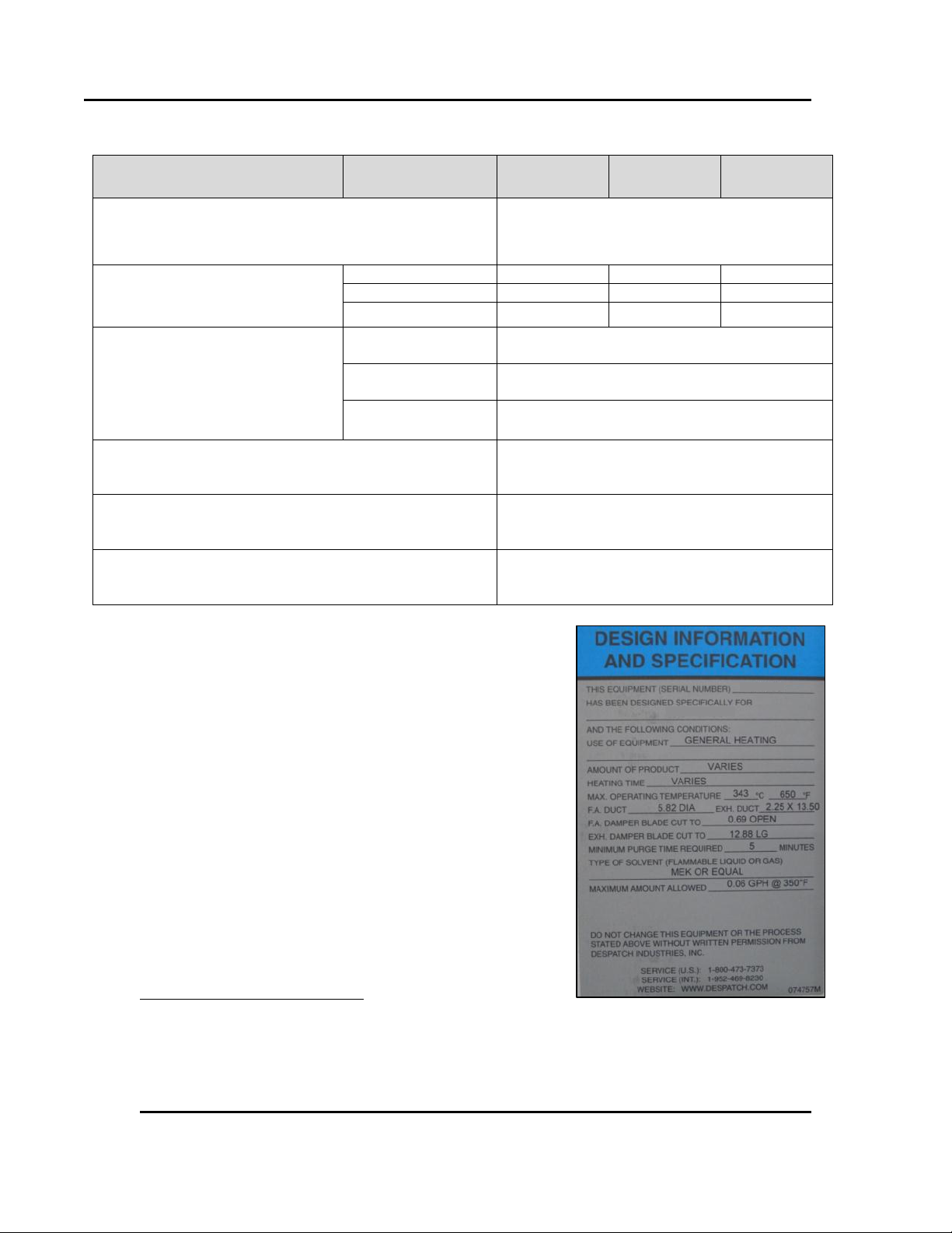
Figure 1.
Design
Information
and
Specification
Label.
10 Version 1
1.5.3. Temperatures
Refer to the Design Information and Specification labels on
your oven for temperature specifics pertaining to your oven
(Figure 1).
Uniformity figures are based on a nine-point test conducted in an empty oven after stabilization period.
Uniformity can vary slightly depending on unit and operating conditions. Minimum operating temperature
and cooling times are based on 20ºC ambient temperature measured at the fresh air inlet with the fresh air
and exhaust dampers fully open. Specifications are subject to change without notice.
All rights reserved. No part of the contents of this manual may be reproduced, copied or transmitted in any form or by any
means including graphic, electronic, or mechanical methods or photocopying, recording, or information storage and
retrieval systems without the written permission of Despatch Industries, unless for purchaser's personal use.
Copyright © 2012 by Despatch Industries.
Page 11
RFD Oven Series Owner’s Manual ABOUT THIS MANUAL
Model
Volts†
Amps
Hertz‡
Electrical Phase
KW
RFD2-13
208
55.9
60
3
18
240
44.5
16
480
22.2
16
RFD2-19
208
55.9
60
3
18
240
44.5
16
480
22.2
16
RFD2-35
208
84
60
3
27
240
86
32
480
43
32
†
‡
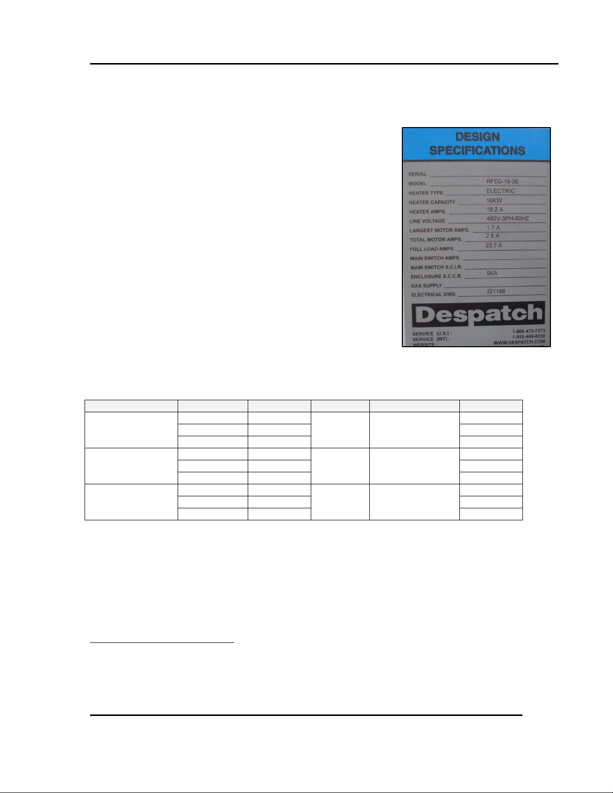
Figure 2. Electrical Specification Label.
Version 1 11
1.5.4. Power
Line voltages may vary in some geographies. If the line voltage for
your RFD oven varies more than 10% from the oven voltage rating,
electrical components such as relays and temperature controls may
operate erratically.
If the line voltage is lower than the oven voltage rating, heat-up
time may be significantly longer and motors may overload or
run hot
If the line voltage is higher than the nameplate rating, motors
may run hot and draw excessive amperage
Refer to the Electrical Specifications on your oven for the specifics
pertaining to your oven (Figure 2).
An oven designed for 240 volts (see oven nameplate) will operate satisfactorily on a minimum of 208
Volts, but will result in 25% reduced heater output. If your power characteristic is lower, contact Despatch
Industries.
50 hertz electrical is available on all models.
All rights reserved. No part of the contents of this manual may be reproduced, copied or transmitted in any form or by any
means including graphic, electronic, or mechanical methods or photocopying, recording, or information storage and
retrieval systems without the written permission of Despatch Industries, unless for purchaser's personal use.
Copyright © 2012 by Despatch Industries.
Page 12
ABOUT THIS MANUAL RFD Oven Series Owner’s Manual
Danger!
Class A ovens are designed for a specific amount of solvent.
Exceeding this amount could result in an explosion. Refer to
Design Specification Label (Figure 14) or Section 1.5.2 for the
solvent handling capabilities of this oven. Do not process
closed containers of any substance or liquid in this oven
because they may explode under heat. In case of fire, leave
door(s) as they are. Shut off electricity. Shut off fuel. Call the
fire department. Stay away.
12 Version 1
1.5.5. Capability
The RFD oven is specifically designed for Class A NFPA 86 requirements, in which flammable
solvents are present. They include a pressure relief panel, purge timer and exhaust fan. Please
note the solvent handling capabilities and do not exceed.
All rights reserved. No part of the contents of this manual may be reproduced, copied or transmitted in any form or by any
means including graphic, electronic, or mechanical methods or photocopying, recording, or information storage and
retrieval systems without the written permission of Despatch Industries, unless for purchaser's personal use.
Copyright © 2012 by Despatch Industries.
Page 13
RFD Oven Series Owner’s Manual SAFETY
Danger!
Electrical panels contain high voltage. Disconnect and lock out
the power supply before working inside any electrical panels.
Failure to lock out the power supply can result in death or injury.
Danger!
An accidental start-up, while working on the RFD oven, can
result in serious injury or death.
Version 1 13
2. Safety
2.1. Safety Information
Do not work on the RFD oven without reading and understanding this section which contains
important information and warnings. Ignoring these warnings can result in death, serious injury or
damage to the machine and product.
2.1.1. Lockout
Machine lockout places the RFD oven into a zero energy state and prevents accidental machine
start up. Always follow the Lockout Procedure described in this section before cleaning,
maintaining or repairing the RFD oven.
2.1.1.1. Lockout Requirements
1. Every power source that can energize any element of the RFD oven must be shut off at the
closest possible power source. This includes air, water, electricity, and the Disconnect
Switch.
2. After energy sources are locked out, test to ensure circuits are de-energized.
2.1.1.2. Lockout Procedure
Personnel authorized to lockout equipment must have the necessary locks to perform the lockout.
1. Physically disconnect all electrical power to the machine or lockout the appropriate breaker
or disconnects.
2. Close all valves and bleed off any pressure.
3. Test for power by attempting a start with the machine controls.
4. Identify the Lockout Condition with a tag on the electrical disconnect and pneumatic shut off
valve.
5. When work is complete, remove all tags and restore the machine to its working state.
All rights reserved. No part of the contents of this manual may be reproduced, copied or transmitted in any form or by any
means including graphic, electronic, or mechanical methods or photocopying, recording, or information storage and
retrieval systems without the written permission of Despatch Industries, unless for purchaser's personal use.
Copyright © 2012 by Despatch Industries.
Page 14
SAFETY RFD Oven Series Owner’s Manual
Danger!
High voltage present on this equipment, service by authorized
personnel only. Contact with energized electrical sources may
result in serious injury or death.
Danger!
Always disconnect all power before extinguishing a fire.
Attempting to extinguish a fire in a machine connected to
electrical power can result in serious injury or death.
14 Version 1
2.2. Maintenance
Only qualified and trained personnel should perform maintenance or repair.
2.3. Electrical Power
Only qualified and trained personnel should perform electrical maintenance or electrical repair.
Before performing maintenance, disconnect all electrical power from the machine. Use a
padlock and lockout all disconnects feeding power to the machine.
Never clean or repair the oven when in operation.
Unauthorized alterations or modifications to RFD oven are strictly forbidden. Never modify
any electrical circuits. Unauthorized modifications can impair the function and safety of the
RFD oven.
2.4. Fire
Keep the RFD oven clean and free of scrap materials, oil or solvents to prevent the possibility of
fire. In the event of fire, follow these steps.
1. Leave door as is.
2. Shut off electricity.
3. De-energize the machine immediately by turning OFF the DISCONNECT SWITCH.
4. Turn off the remote main disconnect (customer supplied disconnect).
5. Shut off fuel.
6. Call the fire department.
7. Stay away.
2.5. Equipment Lockout Requirements
To prevent injury or equipment damage during inspection or repair, the RFD oven must be locked
out.
All rights reserved. No part of the contents of this manual may be reproduced, copied or transmitted in any form or by any
means including graphic, electronic, or mechanical methods or photocopying, recording, or information storage and
retrieval systems without the written permission of Despatch Industries, unless for purchaser's personal use.
Copyright © 2012 by Despatch Industries.
Page 15

RFD Oven Series Owner’s Manual SAFETY
Figure 3. Disconnect
Switch.
Version 1 15
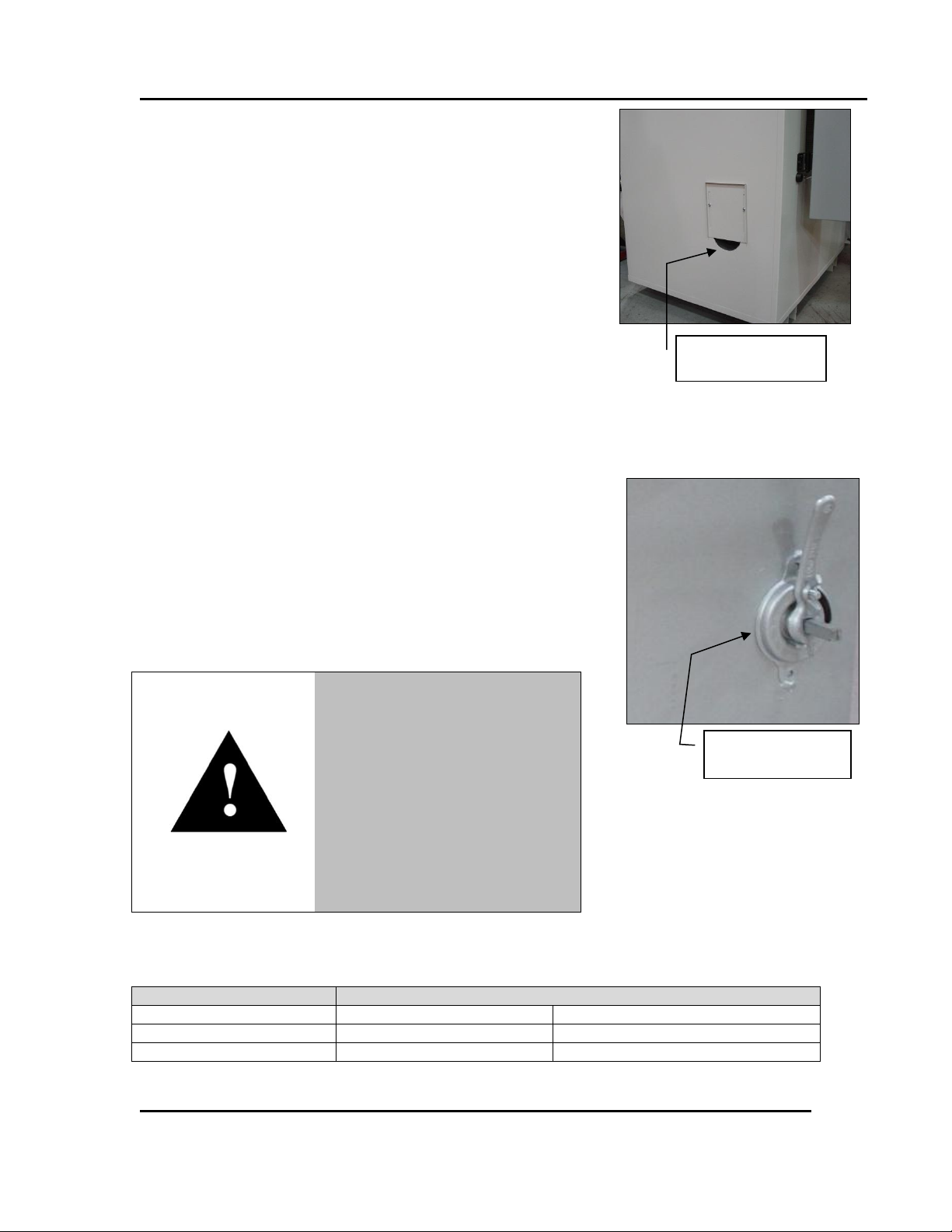
2.5.1. Optional Disconnect Switch
The RFD oven has an optional Disconnect Switch (Figure 3). This Disconnect Switch is
connected to the load break switch behind the panel that disconnects or connects power from the
main line. When a risk of personal injury or damage to the RFD oven exists, turn OFF the
DISCONNECT SWITCH on the front of the oven. This shuts off all
electrical power to the oven.
Copyright © 2012 by Despatch Industries.
All rights reserved. No part of the contents of this manual may be reproduced, copied or transmitted in any form or by any
means including graphic, electronic, or mechanical methods or photocopying, recording, or information storage and
retrieval systems without the written permission of Despatch Industries, unless for purchaser's personal use.
Page 16
THEORY OF OPERATION RFD Oven Series Owner’s Manual
Danger!
Class A ovens are designed for a specific amount of solvent. Exceeding
this amount could result in an explosion. Refer to Design Specification
Label (Figure 14) or Section 1.5.2 for the solvent handling capabilities of
this oven. Do not process closed containers of any substance or liquid
in this oven because they may explode under heat. In case of fire, leave
door(s) as they are. Shut off electricity. Shut off fuel. Call the fire
department. Stay away.
Notice
With the damper in full closed position, a predetermined amount of
fresh air enters the chamber via cutaways in the fresh air and exhaust
dampers. This amount of fresh air meets NFPA86 Safety Guidelines for
Class A ovens.
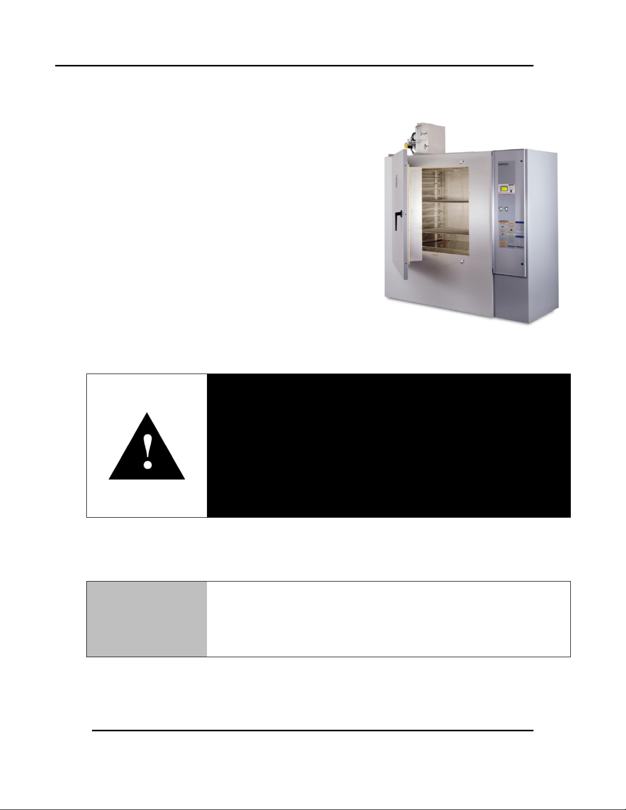
Figure 4. RFD Oven Series.
16 Version 1
3. Theory of Operation
3.1. The RFD Oven Series
Despatch RFD ovens feature horizontal recirculating airflow
to ensure exceptional temperature uniformity throughout the
oven. A high-volume fan circulates air through perforated,
stainless steel walls to create a constant horizontal airflow
across all sections of the oven. The result is proven
reliability in demanding production and laboratory
applications, such as curing, drying, sterilizing, aging, and
other process-critical applications.
The RFD ovens are for applications that include flammable
solvents or large amounts of moisture removal. These Class
A ovens are specially designed to meet NFPA 86
requirements. They include a pressure relief panel, purge
timer and exhaust fan.
All rights reserved. No part of the contents of this manual may be reproduced, copied or transmitted in any form or by any
means including graphic, electronic, or mechanical methods or photocopying, recording, or information storage and
retrieval systems without the written permission of Despatch Industries, unless for purchaser's personal use.
Copyright © 2012 by Despatch Industries.
Page 17
RFD Oven Series Owner’s Manual THEORY OF OPERATION
Fresh Air Damper
Control
Exhaust Damper
Control
Warning!
Maintain slight positive pressure
to regulate heat.
Too much positive pressure in an
oven can create a high outer skin
temperature as hot air is forced
out through panel joints and
around door seal. High outer skin
temperature could warp the front
of the oven.
Damper
Position
Fresh Air
Open
Closed
Exhaust
Closed
Open
Chamber Pressure
Positive
Negative
Figure 5. RFD Fresh Air Damper
Control.
Figure 6. RFD Exhaust Damper
Control.
Version 1 17
3.2. Damper Control
The RFD Series oven includes a manually adjustable fresh air
damper mechanism which controls the flow of fresh air into the
chamber. The fresh air damper control is located on the left side of
the oven (Figure 5 and Figure 6). The oven also includes a
manually adjustable exhaust damper located on the exhaust stack
on top of the oven (Figure 6).
Fresh air and exhaust dampers (Figure 5) control the amount of air
exchanged as well as the oven chamber pressure. The RFD exhaust
damper and fresh air damper are designed to remain slightly open
to allow gases released from processed solvents to escape. In
“closed” position, the dampers are actually slightly open. When the
fresh air damper is closed and the exhaust damper is open, oven
chamber pressure tends toward negative. When the fresh air
damper is open and the exhaust damper is closed, the oven chamber
pressure tends toward positive (Table 1).
A negative oven pressure may draw ambient air into any opening,
causing cool spots to occur. The slightly pressurized chamber
produces the effect of pushing air to the corners of the chamber.
However, too much positive pressure may force hot air or process
vapors out of any openings in the oven into the work area. Ideally,
the fresh air and exhaust dampers should be closed as much as
possible and the oven should be maintained at a neutral or slightly
positive pressure.
Table 1. Damper Positions for Chamber Pressure.
All rights reserved. No part of the contents of this manual may be reproduced, copied or transmitted in any form or by any
means including graphic, electronic, or mechanical methods or photocopying, recording, or information storage and
retrieval systems without the written permission of Despatch Industries, unless for purchaser's personal use.
Copyright © 2012 by Despatch Industries.
Page 18

THEORY OF OPERATION RFD Oven Series Owner’s Manual
When the damper is in full open position, the oven may not be
able to heat to the maximum oven operating temperature.
18 Version 1
3.2.1. Determining Damper Settings
The optimum setting for the amount of fresh air that should be distributed into the chamber
depends on several factors. These factors include ambient environment temperature, load
conditions, load distribution, heat-up rates, cool-down rates, desired temperature uniformity and,
most importantly, the desired operating temperature. Carefully consider existing engineering
tradeoffs while using guidelines to determine the fresh air damper setting.
In general, the damper should be set so that the amount of fresh air flowing into the chamber
agrees with the desired operating temperature conditions. The following paragraphs show the
considerations involved with various damper position settings.
3.2.1.1. Fresh Air Damper Fully Closed Position
The chamber achieves maximum attainable heat-up rates when the fresh air damper lies in the full
closed position. With the damper in the full closed position, the chamber will operate at the
desired temperature using the minimum amount of power. In most cases, the oven also efficiently
operates at the chamber’s maximum operating temperature when in the full closed position.
3.2.1.2. Fresh Air Damper Fully Open Position
The chamber operates at its minimum operating temperature with the fresh air damper in full
open position.
Friction heat from the air recirculation system builds up in the chamber. This causes chamber
temperature to rise slightly even without the heating system on. The chamber reaches thermal
equilibrium temperature after the recirculation motor runs for an extended period of time.
The chamber cannot readily dissipate heat generated by friction without a fully open fresh air
damper. With the fresh air damper fully open, the thermal equilibrium temperature is the minimum operating temperature of the chamber.
3.2.1.3. Exhaust Damper Control
Adjusting the exhaust damper (Figure 6) aids in pressurizing the chamber.
All rights reserved. No part of the contents of this manual may be reproduced, copied or transmitted in any form or by any
means including graphic, electronic, or mechanical methods or photocopying, recording, or information storage and
retrieval systems without the written permission of Despatch Industries, unless for purchaser's personal use.
Copyright © 2012 by Despatch Industries.
Page 19
RFD Oven Series Owner’s Manual THEORY OF OPERATION
This section applies only to ovens that include the optional
adjustable louvers. Ovens without the louver option do not have
adjustable airflow.
Optional adjustable
Version 1 19
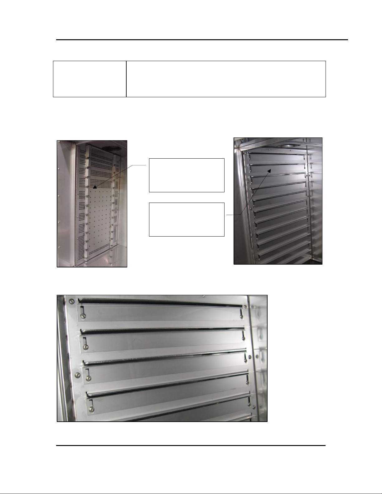
3.3. Optional Adjustable Louvers
RFD oven series come standard with perforated supply and exhaust panels (Figure 7). Optional
adjustable louvers provide an extra measure of airflow customization (Figure 7). Figure 7 shows
the initial factory settings for the optional louvers.
Standard perforated
panels
louvers
Figure 7. Standard perforated panels and adjustable louvers.
Figure 8. Initial factory settings for optional louvers.
All rights reserved. No part of the contents of this manual may be reproduced, copied or transmitted in any form or by any
means including graphic, electronic, or mechanical methods or photocopying, recording, or information storage and
retrieval systems without the written permission of Despatch Industries, unless for purchaser's personal use.
Copyright © 2012 by Despatch Industries.
Page 20

THEORY OF OPERATION RFD Oven Series Owner’s Manual
Warning!
Maintain slight positive pressure to regulate heat.
Too much positive pressure in an oven can create a high outer
skin temperature as hot air is forced out through panel joints
and around door seal. High outer skin temperature could warp
the front of the oven.
Notice
It is particularly important that the oven operators have a
practical understanding of the automatic controls. These
regulate the temperature, provide safety features and generally
govern the consistently uniform and satisfactory performance
of the oven.
20 Version 1
3.3.1. Purpose of Adjustable Airflow
Optional adjustable airflow has several purposes in the RFD oven:
1. Ability to get the best temperature and airflow uniformity.
2. Ability to “spot heat” special areas or specific parts of load.
3. Ability to prevent air flowing out or sucking in through the entrance and exit openings in the
oven.
3.3.2. Supply Air Adjustment
The adjustment of supply louvers is directly related to temperature uniformity in the work
chamber. A general guideline is that more heat is required next to doors, windows and outside
walls so, therefore, more air is required to deliver that heat.
3.3.3. Return Air Adjustment
Ensure there are no restrictive conditions which may limit the amount of air handled by the return
ducts. Restrictions in return air ducts may decrease the amount of air handled by the fan and/or
may result in pressurized conditions in the work chamber. The initial settings for return louvers
should be 50% more open than the supply louvers. Final adjustment may be necessary.
3.4. The Protocol 3 Controller
The Protocol 3™ is a microprocessor based digital temperature controller designed for simple
and flexible oven operation (Figure 9). The Protocol 3 controller operates as a dual-functioning
All rights reserved. No part of the contents of this manual may be reproduced, copied or transmitted in any form or by any
means including graphic, electronic, or mechanical methods or photocopying, recording, or information storage and
retrieval systems without the written permission of Despatch Industries, unless for purchaser's personal use.
Copyright © 2012 by Despatch Industries.
Page 21

RFD Oven Series Owner’s Manual THEORY OF OPERATION
The purchaser is responsible for setting the High Limit Control
per the instructions in this manual.
Danger!
Failure to attend to High Limit Control Warning may result in
property damage, serious bodily injury or death.
Figure 9. Protocol 3 Operator Interface.
Version 1 21
controller/High Limit instrument. The control portion utilizes a time proportioning voltage signal
to control heating devices with minimal temperature fluctuations.
The High Limit portion protects the product and/or the oven from overheating. If the product
being processed has a critical high temperature limit, the High Limit setpoint should be set to a
temperature somewhat below the temperature at which the product could be damaged. If the
product does not have a critical high temperature limit, the High Limit setpoint should be set 5 to
15 degrees higher than the maximum programmed setpoint at which the oven will operate.
The Protocol 3 controller provides three primary operating modes:
Manual: Oven operates continuously at a fixed temperature until turned off.
Timer: Oven operates at a fixed temperature for a user-selected time period, and then
automatically turns off.
Profile: Temperatures increase or decrease as defined by 255 segments that can be allocated
to 64 ramp and soak profiles. The profiles can be linked to provide additional temperature
combinations.
Review the Protocol 3 Controller Owner’s Manual for more information.
All rights reserved. No part of the contents of this manual may be reproduced, copied or transmitted in any form or by any
means including graphic, electronic, or mechanical methods or photocopying, recording, or information storage and
retrieval systems without the written permission of Despatch Industries, unless for purchaser's personal use.
Copyright © 2012 by Despatch Industries.
Page 22

THEORY OF OPERATION RFD Oven Series Owner’s Manual
RFD Model
Purge Timer Setting
RFD2-13
4 minutes
RFD2-19
5 minutes
RFD2-35
2.5 minutes
Figure 10. The Purge timer red light is
illuminated during the timing period.
Figure 11. Airflow interlocking safety switch.
22 Version 1
3.5. Optional High Limit Audible Alarm
High Limit audible and visual alarm is a red light (Figure 13) and small alarm horn located on the
front of the control panel. The alarm is sounded if a High Limit condition occurs. A switch is
provided to silence the alarm. This alarm has a range of 80dB at 2 ft (0.6 m).
3.6. Purge Timer
The Purge timer (Figure 10) prevents the heater from
energizing until flammable solvents within the oven
have been reduced to a safe level by the forced exhaust
system. The red light of the Purge timer illuminates
during the purge cycle.
The Purge timer is pre-set at the factory for the
appropriate purge time. Table 2 and the specification
label (Figure 14) list the appropriate settings. Verify
the setpoint before each use. If the purge time is not
set to the value shown in Table 2 or on the
specification label, adjust as necessary.
Table 2. Purge timer settings for various RFD models.
3.7. Airflow Interlocking Safety Switch
The Airflow Interlocking Safety Switch interrupts power to the heater if the forced exhaust
system is not functioning properly (Figure 11).
If the Airflow Interlocking Safety Switch is set too low,
it will not interrupt power to the heater (if the forced
exhaust system were not functioning properly). If the
Airflow Interlocking Safety Switch is set too high, the
heater will not energize, even if the forced exhaust
system is functioning properly. The Airflow Interlocking
Safety Switch setpoint is pre-set at the factory but must
be verified before each use (see Section 6.5 for
adjustment information).
All rights reserved. No part of the contents of this manual may be reproduced, copied or transmitted in any form or by any
means including graphic, electronic, or mechanical methods or photocopying, recording, or information storage and
retrieval systems without the written permission of Despatch Industries, unless for purchaser's personal use.
Copyright © 2012 by Despatch Industries.
Page 23

RFD Oven Series Owner’s Manual ASSEMBLY & SETUP
Danger!
This equipment must be installed by a licensed electrician who
is experienced with combustion safeguard control systems and
understands the functions of an interlocking switch such as gas
pressure switches.
If any warning, danger, or information sign has been
damaged or lost, contact the customer service department of
Despatch Industries, Inc. for replacement.
Version 1 23
4. Assembly & Setup
Assembly and Setup provides directions for unpacking and installing your RFD oven.
4.1. Unpack & Inspect The RFD Oven
Remove all packing materials or devices and thoroughly inspect the oven for any damage that
might have occurred during shipment.
Note the condition of the carton and plastic cover sheet inside the carton.
Observe all outside surfaces and corners of the oven for scratches and dents.
Check oven controls and indicators for normal movement, bent shafts, cracks, chips or
missing parts such as knobs and lenses.
Check the door and latch for smooth operation.
4.1.1. If Damaged During Shipping
If damage occurred during shipping:
1. Contact the shipper immediately and file a written damage claim.
2. Contact Despatch Industries (1-800-473-7373 or 1-952-469-8230 or service@despatch.com)
to report your findings and to order replacement parts for those damaged or missing. Send a
copy of your filed damage claims to Despatch Industries (Despatch Industries, 8860 207th
3. Street, Lakeville, MN 555044, USA).
4. Check the packing list to ensure you received all the specified components of the oven
system. Contact Despatch Industries to have any missing products forwarded to you.
5. Complete the warranty card and mail it to Despatch within 15 days after receipt of the
equipment.
4.2. Set up The RFD Oven
4.2.1. Select Oven Location
The Despatch RFD oven is designed to operate in an industrial setting.
All rights reserved. No part of the contents of this manual may be reproduced, copied or transmitted in any form or by any
means including graphic, electronic, or mechanical methods or photocopying, recording, or information storage and
retrieval systems without the written permission of Despatch Industries, unless for purchaser's personal use.
Copyright © 2012 by Despatch Industries.
Page 24

ASSEMBLY & SETUP RFD Oven Series Owner’s Manual
Notice
Review oven weight to ensure the foundation is adequate to hold
the weight.
Warning!
Do not use the oven in wet, corrosive or explosive atmospheres
unless this oven is specifically designed for a special
atmosphere.
Notice
If more than two elbows are used in the stack, over all airflow
will be reduced. If airflow is reduced, the amount of solvent that
can be safely used with the equipment must also be reduced.
Figure 12. RFD Forced Exhaust
Assembly.
24 Version 1
4.2.1.1. Placement Requirements
Place oven directly on the floor.
Allow adequate clearance for explosion relief. Minimum clearance for explosion relief is 18
in. above the oven.
Plumb and level the oven to assure proper heat distribution and operation of all mechanical
components.
Do not expose oven to excessive vibration and affix all electrical cabinets.
If placing the oven in an area where excessive particulate matter exists (such as a construction
site or coal processing center), periodically clean all its electrical compartments. Keep power
supply within the specifications provided by Despatch, and use a line conditioner for a
facility with an unstable power supply.
4.3. Exhaust Connections
The RFD oven exhaust discharge opening is located on
the top left of the oven (Figure 12). Install an exhaust
stack from the discharge opening to the outside of the
building. The discharge opening size is 8.9 x 21.6 cm (3
½ x 8 ½ inches).
All rights reserved. No part of the contents of this manual may be reproduced, copied or transmitted in any form or by any
means including graphic, electronic, or mechanical methods or photocopying, recording, or information storage and
retrieval systems without the written permission of Despatch Industries, unless for purchaser's personal use.
Copyright © 2012 by Despatch Industries.
Page 25

RFD Oven Series Owner’s Manual ASSEMBLY & SETUP
The oven must be hardwired directly to the electric supply.
Verify proper fan rotation on initial start-up and recheck rotation
whenever wiring or electrical component changes are made.
Each fan has an arrow showing correct rotation.
Danger!
All grounding and safety equipment must be in compliance with
applicable codes, ordinances and accepted safe practices.
Notice
Flashing through roof or wall must be capable of handling
temperatures up to 343°C (650°F).
All stacks must comply with state and local building codes to
ensure that surrounding combustible surfaces are below 71°C
(160°F).
Version 1 25
4.4. Wiring & Power Connections
See electrical schematics in Section 8.3 for line connections.
All rights reserved. No part of the contents of this manual may be reproduced, copied or transmitted in any form or by any
means including graphic, electronic, or mechanical methods or photocopying, recording, or information storage and
retrieval systems without the written permission of Despatch Industries, unless for purchaser's personal use.
Copyright © 2012 by Despatch Industries.
Page 26

OPERATION RFD Oven Series Owner’s Manual
Users and operators of this oven must comply with operating
procedures and training of operating personnel as required by
the Occupational Safety and Health Act (OSHA) of 1970, Section
5 and relevant safety standards, and other safety rules and
regulations of state and local governments. Refer to the relevant
safety standards in OSHA and National Fire Protection
Association (NFPA), Section 86 of 1985.
Danger!
Class A ovens are designed for a specific amount of flammable
solvent. Exceeding this amount could result in an explosion.
Refer to Design Specification Label (Figure 2) or Section 1.5.2
for the solvent handling capabilities of this oven.
Danger!
In case of fire, leave door(s) as they are. Shut off electricity.
Shut off fuel. Call the fire department. Stay away.
Despatch Industries cannot be responsible for either the
process or process temperature used, or for the quality of the
product being processed. It is the responsibility of the
purchaser and operator to see that the product undergoing
processing in a Despatch oven is adequately protected from
damage.
Carefully following the instructions in this manual will help the
purchaser and operator in fulfilling that responsibility.
26 Version 1
5. Operation
5.1. Load Oven
Avoid spilling on the heater elements or oven floor when loading the oven. Do not place the load
on the oven floor plate. Placing the load on the oven floor may cause the load to heat unevenly
and the weight may cause shorting out of the heater elements. Use the shelves provided.
Copyright © 2012 by Despatch Industries.
All rights reserved. No part of the contents of this manual may be reproduced, copied or transmitted in any form or by any
means including graphic, electronic, or mechanical methods or photocopying, recording, or information storage and
retrieval systems without the written permission of Despatch Industries, unless for purchaser's personal use.
Page 27

RFD Oven Series Owner’s Manual OPERATION
Caution!
Always place loads on the shelves provided to avoid possible
uneven heating and damage to the oven.
For best results:
Do not place the load within 7.62cm (3 inches) of louvers
or within 15.25cm (6 inches) of the chamber ceiling
Stagger the load within the chamber to allow as much air
as possible to circulate from the supply side to the
return side of the oven
Version 1 27
The two shelves are designed to be pulled out about halfway without tipping. Do not overload the
shelves. Shelf support capacity is listed in the Capacities section (1.5.2). Do not overfill the oven.
Distribute the workload evenly so airflow is not restricted. The workload should not take up
more than two-thirds of any dimension of the inside cavity.
5.2. Pre-Startup Checklist
Read this manual carefully and make use of its instructions and explanations. Safe,
continuous, satisfactory and trouble-free operation depends primarily on your degree of
understanding of the system and your willingness to keep all parts in proper operating
condition.
Verify line voltage. Voltage must correspond to nameplate requirements of motors and
controls. Incorrect line voltage can result in serious damage. Refer to Section 1.5.4 for more
information.
Check fresh air and exhaust openings. The dampers have been designed to remain slightly
open to allow processed solvent gases to escape. Do not be careless about restrictions in and
around the fresh air and exhaust openings and stacks. Refer to Sections 1.5.2 and 4.3 for
information on exhaust specifications and requirements. Under no condition can they be
permitted to become so filled with dirt that they reduce airflow.
For drying application, open exhaust damper to prevent buildup of moisture.
All rights reserved. No part of the contents of this manual may be reproduced, copied or transmitted in any form or by any
means including graphic, electronic, or mechanical methods or photocopying, recording, or information storage and
retrieval systems without the written permission of Despatch Industries, unless for purchaser's personal use.
Copyright © 2012 by Despatch Industries.
Page 28

OPERATION RFD Oven Series Owner’s Manual
If polarity is reversed during wiring, the fan will rotate
backwards and compromise proper ventilation.
Figure 13. Power, Heat and Alarm Silence Switches.
Figure 14. Minimum purge time is listed on the
RFD oven design specification label.
28 Version 1
5.3. Operating Procedure
5.3.1. Check Fan Rotation and Other Preliminaries
1. Check fan rotation after the initial installation
and after reconnecting the power supply to
ensure the fans are running in the correct
direction. To check fan rotation:
a. Momentarily toggle POWER (Figure 13)
to start fans and check rotation.
b. Rotation should correspond to the
directional arrows provided.
c. Reverse motor rotation where necessary.
2. Verify purge timer (Figure 10) is set to the
correct value as it appears on the Design
Specification (Figure 14) or Table 2.
3. Verify airflow switches:
a. Are properly installed
b. Proper make and break for the contacts
when fans are started and stopped.
c. Refer to Section 3.7 and Section for 6.5
more information on airflow switches.
All rights reserved. No part of the contents of this manual may be reproduced, copied or transmitted in any form or by any
means including graphic, electronic, or mechanical methods or photocopying, recording, or information storage and
retrieval systems without the written permission of Despatch Industries, unless for purchaser's personal use.
Copyright © 2012 by Despatch Industries.
Page 29

RFD Oven Series Owner’s Manual OPERATION
Never operate oven at a temperature above the maximum
operating temperature: 343°C (650°F)
Notice
The heater of the Class A oven cannot be energized until the
forced exhaust system has brought in a minimum amount of
fresh air into the chamber. The purge timer provided prevents
the heater from energizing until the oven has had enough time
to bring in the required amount of fresh air. The airflow switch,
which closes when the exhaust system is running, energizes
the purge timer. The predetermined purge time for the RFD
oven is specified in Section 3.6.
Warning!
Fans should remain in operation until the oven temperature is below
149ºC (300ºF) to prevent damage to the fan and/or motor bearings.
Version 1 29
5.3.2. Start and Operate the Oven
1. Set the main Power Disconnect switch to ON (Figure 3).
2. Set POWER to ON. The recirculation fan will start, and the purge timer will begin timing.
3. Set HEAT to ON (Figure 13).
a. The Heater LED on the controller will light indicate the heater is on and the controller is
calling for heat.
b. The alarm horn will sound if the High Limit trips. Press the ALARM SILENCE to silence
the alarm.
c. Allow the oven to cool below the High Limit setting and reset the High Limit.
4. When the door is opened the heater will shut off.
5. Operate the temperature control as desired. If necessary, refer to the Protocol 3 Owner’s
Manual for more instruction.
5.3.3. Shutdown
1. Set HEATER to OFF.
2. Allow the fans to run until the oven has cooled below 149ºC (300ºF).
3. Set POWER to OFF.
Copyright © 2012 by Despatch Industries.
All rights reserved. No part of the contents of this manual may be reproduced, copied or transmitted in any form or by any
means including graphic, electronic, or mechanical methods or photocopying, recording, or information storage and
retrieval systems without the written permission of Despatch Industries, unless for purchaser's personal use.
Page 30

OPERATION RFD Oven Series Owner’s Manual
Global Headquarters
Contact
Service & Technical
Support
Despatch Industries
8860 207th Street
Lakeville, MN 55044
USA
International/Main: 1-952-469-5424
US toll free: 1-888-337-7282
Fax: 1-952-469-4513
info@despatch.com
www.despatch.com
Service: 1-952-469-8230
US toll free: 1-800-473-7373
Service @despatch.com
30 Version 1
If additional information is required regarding the operation of this equipment, please contact
Despatch.
5.3.4. Working with Protocol 3 Operating Modes
Refer to the Protocol 3 Controller’s Owner Manual for specific information for working
with the controller.
All rights reserved. No part of the contents of this manual may be reproduced, copied or transmitted in any form or by any
means including graphic, electronic, or mechanical methods or photocopying, recording, or information storage and
retrieval systems without the written permission of Despatch Industries, unless for purchaser's personal use.
Copyright © 2012 by Despatch Industries.
Page 31

RFD Oven Series Owner’s Manual MAINTENANCE
Danger!
Disconnect all power sources before making repairs. Contact
with energized electrical sources may result in serious injury or
death.
Version 1 31
6. Maintenance
Do not attempt any service on this oven before setting the main power Disconnect Switch to
OFF.
6.1. Checklist
Keep equipment clean. Gradual dirt accumulation retards airflow. A dirty oven can result in
unsatisfactory operation such as unbalanced temperature in the work chamber, reduced
heating capacity, reduced production, and the like. Keep the walls, floor and ceiling of the
oven work chamber free of dirt, dust, smoke, solvent vapors, or other contaminations.
Keep all equipment accessible. Allow space for good circulation. Do not permit other
materials to be stored or piled against it.
Do not place load too close to the supply duct. The supply air temperature is somewhat higher
than average work space temperature and may overheat or otherwise damage product.
Do not put product on the floor or in isolated corners where air movement and temperature
are not likely to be at average conditions.
Do not mix thick heavy parts with light parts. The heavy parts require longer to heat and
should be treated separately.
Check safety controls. This should be done daily and never less than once a week. Establish
maintenance and checkup schedules. Maintain equipment in good repair and adjustment at all
times. Make repairs immediately to avoid costly delays.
All rights reserved. No part of the contents of this manual may be reproduced, copied or transmitted in any form or by any
means including graphic, electronic, or mechanical methods or photocopying, recording, or information storage and
retrieval systems without the written permission of Despatch Industries, unless for purchaser's personal use.
Copyright © 2012 by Despatch Industries.
Page 32

MAINTENANCE RFD Oven Series Owner’s Manual
Preventive
Maintenance
(Refer to Section)
Daily
Weekly
Monthly
Every
Three
Months
Every
Six
Months
Annually
As
Needed
General
Avoid placing load
too close to supply
duct (5.1)
X
Visually inspect for
dirt, debris and free
movement of parts
and controls.
X
Clean as needed
X
Inspect door seals
for proper seating,
damage and/or
tears
X
Inspect door
operation. Doors
should open and
close securely,
without jerking or
slamming.
X
Check optional
Disconnect Switch
(2.5.1)
X
Time to temperature:
record heating times
for similar loads. If
heating times are
slowing, it could
indicate a need for
maintenance.
X
Ventilation
Check fresh air
damper (3.2)
X
Check fan vibration:
supply and exhaust
(6.3)
X
Inspect optional
louvers (3.3)
X
Check fan rotation
(5.3.1)
X
Electrical
Test airflow switch
(6.5)
X
32 Version 1
6.2. Maintenance Schedule
All rights reserved. No part of the contents of this manual may be reproduced, copied or transmitted in any form or by any
means including graphic, electronic, or mechanical methods or photocopying, recording, or information storage and
retrieval systems without the written permission of Despatch Industries, unless for purchaser's personal use.
Copyright © 2012 by Despatch Industries.
Page 33

RFD Oven Series Owner’s Manual MAINTENANCE
Preventive
Maintenance
(Refer to Section)
Daily
Weekly
Monthly
Every
Three
Months
Every
Six
Months
Annually
As
Needed
Check High limit
controller (6.8)
X
Verify purge timer
setting (6.4)
X
Version 1 33
6.3. Check Fans
Check fan operation by closely observing for abnormal movement or sound. Irregular noise or
movement may mean the fan needs repair or replacement. Listen for any irregular noises coming
from the fans.
6.4. Test Purge Timer
Test the Purge timer regularly to ensure continued safe operation:
1. Check the minimum purge time setting on the RFD Oven name plate (Figure 14).
2. Verify the Purge timer is set to the setting on the RFD name plate (Figure 10).
6.5. Test Airflow Switch
6.5.1. To Set or Adjust Airflow Switch
6.5.2. Example: Verify Exhaust Fan Airflow Switch Setpoint
Testing the airflow switch ensures that power to the heater is interrupted if the forced
exhaust system is not functioning properly. This section provides an example test
procedure along with a procedure for adjusting the airflow switch. If testing or adjusting
the airflow switch prove unsuccessful, contact Despatch for service information (see
Section 1.2).
The position of the top of the adjustment screw indicates the switch pressure setting. View the
pressure setting through the slot in the stem (Figure 16). To adjust the airflow switch:
1. Remove the aluminum hex cap on the top of the stem (Figure 16).
2. Increase the setting by turning the inside adjustment screw clockwise (adjustment screw
down).
3. Decrease the setting by turning the inside adjustment screw counter-clockwise (adjustment
screw up).
To test the exhaust fan’s airflow switch setpoint:
1. Set the oven power to ON.
Copyright © 2012 by Despatch Industries.
All rights reserved. No part of the contents of this manual may be reproduced, copied or transmitted in any form or by any
means including graphic, electronic, or mechanical methods or photocopying, recording, or information storage and
retrieval systems without the written permission of Despatch Industries, unless for purchaser's personal use.
Page 34

MAINTENANCE RFD Oven Series Owner’s Manual
OFF position
ON position
Indicator
Window
Figure 15. Airflow Switch Indicator.
34 Version 1
2. Allow the oven to stabilize at its minimum operating temperature by leaving the heater off.
3. Set the oven power to OFF.
4. Verify that the white line in the indicator window of the airflow switch is OFF (Figure 15).
a. If the switch remains ON, increase the airflow switch set point until the switch turns
OFF.
b. A switch setting of 0.2” WC (inches of water column) to 1.0” WC should detect a fan
malfunction.
c. If the switch does not shut off below a setting of 2” WC, the switch is defective.
d. Once the switch turns off, increase the setpoint an additional 0.2” WC.
5. Set the oven power to ON to start the exhaust fan.
6. Verify that the white line in the indicator window of the airflow switch is ON and steady
(Figure 15).
7. If the switch remains OFF, check the fan rotation direction (Section 5.3.1). If the fan rotation
is correct, decrease the airflow switch set point until the switch turns on.
All rights reserved. No part of the contents of this manual may be reproduced, copied or transmitted in any form or by any
means including graphic, electronic, or mechanical methods or photocopying, recording, or information storage and
retrieval systems without the written permission of Despatch Industries, unless for purchaser's personal use.
Copyright © 2012 by Despatch Industries.
Page 35

RFD Oven Series Owner’s Manual MAINTENANCE
the slotted setpoint adjustment
Switch setpoint indicated by the top of the
adjustment screw
WC should detect a fan malfunction
Version 1 35
Remove the hex cap to gain access to
A switch setting of 0.2 in WC to 1.0 in
Figure 16. Adjust the airflow switch.
6.6. Lubrication
Lubricate all door latches, hinges, door operating mechanisms, and wear surfaces to ensure easy
operation.
6.7. Check Safety Controls
Make certain the oven controls are free of dirt and debris and function properly.
6.8. Check High-Limit Controller
The Protocol 3 controller has an integrated high limit function which disables the heater output
when tripped. Check the High Limit controller by:
1. Set the Hi-Limit setpoint below the process temperature. Refer to the Protocol 3 manual as
necessary.
2. The oven should heat and trip the High-Limit controller as it reaches the high limit setpoint.
3. If not, contact Despatch.
All rights reserved. No part of the contents of this manual may be reproduced, copied or transmitted in any form or by any
means including graphic, electronic, or mechanical methods or photocopying, recording, or information storage and
retrieval systems without the written permission of Despatch Industries, unless for purchaser's personal use.
Copyright © 2012 by Despatch Industries.
Page 36

MAINTENANCE RFD Oven Series Owner’s Manual
Global Headquarters
Contact
Service & Technical
Support
Despatch Industries
8860 207th Street
Lakeville, MN 55044
USA
International/Main: 1-952-469-5424
US toll free: 1-888-337-7282
Fax: 1-952-469-4513
info@despatch.com
www.despatch.com
Service: 1-952-469-8230
US toll free: 1-800-473-7373
Service @despatch.com
Danger!
Do not attempt any service on this equipment without setting the
main power Disconnect Switch to OFF. Disconnect all power
sources before making repairs. Contact with energized electrical
sources may result in serious injury or death.
36 Version 1
6.9. Replacement Parts
Contact the Service Products Division at Despatch to order or return parts. The Service Products
features our Response Center for customer service. When returning parts, a Despatch
representative will provide you with an MRA (Material Return Authorization) number, which
must be attached to the returned part for identification. When ordering a replacement part, be sure
to give the model number, serial number, and part number to expedite the process.
Contact Despatch with any service needs.
6.10. Repairs
6.10.1. Protocol 3 Controller
Refer to the Protocol 3 Owner’s Manual for instructions on replacing the Protocol 3 Controller.
All rights reserved. No part of the contents of this manual may be reproduced, copied or transmitted in any form or by any
means including graphic, electronic, or mechanical methods or photocopying, recording, or information storage and
retrieval systems without the written permission of Despatch Industries, unless for purchaser's personal use.
Copyright © 2012 by Despatch Industries.
Page 37

RFD Oven Series Owner’s Manual TROUBLESHOOTING
Difficulty
Probable Cause
Suggested Remedy
Failure to heat or
heats up to only 3550ºC
No power
Check power source and/or oven and wall
fuses
Burned out heater
Replace heater (see warranty, Section 8.1)
Protocol 3 controller
malfunction
Replace controller
Loose wire connections
Disconnect power and check connections behind control panel
Heater relay failure
Replace heater contactor or SCR
Door switch failure (if
installed)
Replace door switch
Slow heat up
Improperly loaded
Reduce load or redistribute load in chamber.
Low line voltage
Supply sufficient power and proper
connections. Check for circuit overload
Heating element(s) are
burned out
Replace heater (see warranty, Section 8.1)
Fan motor failure
Replace fan motor
Frequent heater
element burnout
Harmful fumes generated
by load
Increase vent opening or discontinue process
Spillage or splattering of
material on heater
elements
Disconnect power and clean oven chamber.
Take measures to prevent splattering.
Overheating oven
Check the High Limit
Erratic temperature
or
inaccurate
temperature
Protocol 3 controller
malfunction
Replace controller
Improper tuning
parameters
Check tuning parameters
Protocol 3 controller
miscalibration
Recalibrate controller (see Protocol 3
Controller Owner’s Manual for further
instruction manual).
High Limit setting
High Limit should be 10-25ºC higher than
setpoint.
Defective SCR
Replace SCR
Improper offset
Check zone calibration
Excess surface or
door temperature
Door seal deterioration
Replace door seal.
Improper airflow
Fan motor failure
Replace fan motor
Fan wheel seated too low
Adjust fan wheel for 3/16" clearance between
Version 1 37
7. Troubleshooting
7.1. Troubleshooting: Possible Problems and Solutions
Equipment which operates for long periods of time may develop problems. Table 3 lists possible
problems and suggested solutions. If you have a problem not listed and do not know what to do,
contact Despatch Industries at our toll free Help Line 800-473-7373.
Table 3. Troubleshooting grid.
All rights reserved. No part of the contents of this manual may be reproduced, copied or transmitted in any form or by any
means including graphic, electronic, or mechanical methods or photocopying, recording, or information storage and
retrieval systems without the written permission of Despatch Industries, unless for purchaser's personal use.
Copyright © 2012 by Despatch Industries.
Page 38

TROUBLESHOOTING RFD Oven Series Owner’s Manual
Difficulty
Probable Cause
Suggested Remedy
on fan shaft
wheel and inlet ring
Unbalanced fan wheel
Replace fan wheel
Excessive vibration
Dirty fan wheel
Clean fan
Unbalanced fan wheel
Replace fan wheel
Oven will not
control at setpoint
High Limit set too low
Set the High Limit higher.
Protocol 3 controller
malfunction
Replace controller
SCR malfunction
Replace SCR and/or check control output
voltage.
Air friction of recirculation
fan
Open exhaust air vent. Unit will not control
below minimum operating temperature with
vent closed.
Heater does not
shut down until
temperature
reaches the High
Limit setting
Protocol 3 controller
malfunction
Replace controller.
SCR malfunction
Replace SCR
Danger!
Electrical panels contain high voltage. Disconnect and lock out the
power supply before working inside any electrical panels. Failure to
lock out the power supply can result in death or injury.
Conditions
Actions
A. Non-uniform work
chamber
1. Check to get a lightly positive chamber pressure by closing down
exhaust or opening up fresh air.
a. Review damper instructions (Section 3.2)
b. Adjust optional supply louvers:
i. Open for cold spots
ii. Close for hot spots
c. If necessary, adjust optional return louvers in the same
manner.
38 Version 1
7.2. Troubleshoot Airflow Conditions
Table 4 lists possible problems and remedies for airflow conditions.
Table 4. Airflow Troubleshooting.
All rights reserved. No part of the contents of this manual may be reproduced, copied or transmitted in any form or by any
means including graphic, electronic, or mechanical methods or photocopying, recording, or information storage and
retrieval systems without the written permission of Despatch Industries, unless for purchaser's personal use.
Copyright © 2012 by Despatch Industries.
Page 39

RFD Oven Series Owner’s Manual TROUBLESHOOTING
Conditions
Actions
2. Check motor for proper operation and direction of rotation.
B. Cold by door
1. See A-1.
2. Check door seals.
3. Open optional supply louvers close to door.
C. Positive pressure
in chamber
4. Close fresh air damper.
5. Open exhaust damper.
6. Refer to Damper Control Section 3.2 for more information.
D. Negative pressure
in chamber
1. Close exhaust damper.
2. Open fresh air damper.
3. Open optional supply louvers slightly.
Alarm Status
Possible Problem
Next Step
HI LIMIT LED ON
Problem with thermocouple
High Limit setpoint has been
exceeded.
Once the problem has corrected,
press RESET.
DEV HOLD LED flashing
Oven temperature has not
entered (or dropped out of) the
Auto Hold band and the soak
timer has stopped
Program a slower ramp rate or if oven
is not heating check heater circuit.
Top PV displays OPEN
Control thermocouple is
disconnected or broken
Repair or replace the thermocouple.
HLPV displays OPEN
High Limit thermocouple is
disconnected or broken
Repair or replace the thermocouple.
Version 1 39
7.3. Troubleshooting: Error Messages and Alarm
Table 5 lists the more common error messages, the possible problems and remedies.
Table 5. Error Messages and Next Steps.
All rights reserved. No part of the contents of this manual may be reproduced, copied or transmitted in any form or by any
means including graphic, electronic, or mechanical methods or photocopying, recording, or information storage and
retrieval systems without the written permission of Despatch Industries, unless for purchaser's personal use.
Copyright © 2012 by Despatch Industries.
Page 40

APPENDICES RFD Oven Series Owner’s Manual
40 Version 1
8. Appendices
8.1. Standard Products Warranty
All rights reserved. No part of the contents of this manual may be reproduced, copied or transmitted in any form or by any
Copyright © 2012 by Despatch Industries.
means including graphic, electronic, or mechanical methods or photocopying, recording, or information storage and
retrieval systems without the written permission of Despatch Industries, unless for purchaser's personal use.
Page 41

RFD Oven Series Owner’s Manual APPENDICES
Refer to instructions provided recorder manufacturer for more
specific installation notes.
Parameter Code
Degrees C
Degrees F
Inps
17
17
Icor 0 0
DiSP
On
On
Dpos
0
0
EUU4
400
752
EUL4
0
32
ChUP
400
8005
ChLO
0 0 DFF
1
1
4
5
Version 1 41
8.2. MRC5000 Setup (Optional)
Temperature is retransmitted to the MRC5000 recorder from the controller. Set up the recorder
by:
1. Ensure hardware jumper JU1 is in place for the 5 VDC setting (Refer to MRC5000 Manual
included).
2. Move MODE to PROG/TEST/CAL to display Prog.
3. Press ▼ twice to display Inps. Move to each Parameter Code using ▼or ▲. Adjust each
Parameter Code using the settings in Table 6.
4. After adjusting all settings, move MODE to RUN. Display on both the recorder and controller
should read the same.
Table 6. MRC 5000 Settings.
8.3. Electrical Schematics
The following pages contain electrical schematics for the RFD2-13, 2-19 and 2-35 ovens.
These values must match the settings RetOutLo and RetOutHi on the Protocol 3 Control page. For
example, if RetOutLo is 32, EUL must read 32.
Change 0-400 chart paper to 0-800 chart paper. Depending on the equipment, 0-600 paper may be used if
the maximum temperature is 260°C (500ºF).
All rights reserved. No part of the contents of this manual may be reproduced, copied or transmitted in any form or by any
means including graphic, electronic, or mechanical methods or photocopying, recording, or information storage and
retrieval systems without the written permission of Despatch Industries, unless for purchaser's personal use.
Copyright © 2012 by Despatch Industries.
Page 42

APPENDICES RFD Oven Series Owner’s Manual
Figure 17. RFD2-13-2E, 208V (Drawing 320219-01).
42 Version 1
All rights reserved. No part of the contents of this manual may be reproduced, copied or transmitted in any form or by any means including graphic, electronic, or mechanical methods
or photocopying, recording, or information storage and retrieval systems without the written permission of Despatch Industries, unless for purchaser's personal use.
Copyright © 2012 by Despatch Industries.
Page 43

RFD Oven Series Owner’s Manual APPENDICES
Figure 18. RFD2-13-2E, 208V (Drawing 320219-02).
Version 1 43
All rights reserved. No part of the contents of this manual may be reproduced, copied or transmitted in any form or by any means including graphic, electronic, or mechanical methods
or photocopying, recording, or information storage and retrieval systems without the written permission of Despatch Industries, unless for purchaser's personal use.
Copyright © 2012 by Despatch Industries.
Page 44

APPENDICES RFD Oven Series Owner’s Manual
Figure 19. RFD2-13-2E, 240V (Drawing 320221-01).
44 Version 1
All rights reserved. No part of the contents of this manual may be reproduced, copied or transmitted in any form or by any means including graphic, electronic, or mechanical methods
or photocopying, recording, or information storage and retrieval systems without the written permission of Despatch Industries, unless for purchaser's personal use.
Copyright © 2012 by Despatch Industries.
Page 45

RFD Oven Series Owner’s Manual APPENDICES
Figure 20. RFD2-13-2E, 240V (Drawing 320221-02).
Version 1 45
All rights reserved. No part of the contents of this manual may be reproduced, copied or transmitted in any form or by any means including graphic, electronic, or mechanical methods
or photocopying, recording, or information storage and retrieval systems without the written permission of Despatch Industries, unless for purchaser's personal use.
Copyright © 2012 by Despatch Industries.
Page 46

APPENDICES RFD Oven Series Owner’s Manual
Figure 21. RFD2-13-2E, 480V (Drawing 320223-01).
46 Version 1
All rights reserved. No part of the contents of this manual may be reproduced, copied or transmitted in any form or by any means including graphic, electronic, or mechanical methods
or photocopying, recording, or information storage and retrieval systems without the written permission of Despatch Industries, unless for purchaser's personal use.
Copyright © 2012 by Despatch Industries.
Page 47

RFD Oven Series Owner’s Manual APPENDICES
Figure 22. RFD2-13-2E, 480V (Drawing 320223-02).
Version 1 47
All rights reserved. No part of the contents of this manual may be reproduced, copied or transmitted in any form or by any means including graphic, electronic, or mechanical methods
or photocopying, recording, or information storage and retrieval systems without the written permission of Despatch Industries, unless for purchaser's personal use.
Copyright © 2012 by Despatch Industries.
Page 48

APPENDICES RFD Oven Series Owner’s Manual
Figure 23. RFD2-13-2E Oven Assembly (Drawing 148457-01).
48 Version 1
All rights reserved. No part of the contents of this manual may be reproduced, copied or transmitted in any form or by any means including graphic, electronic, or mechanical methods
or photocopying, recording, or information storage and retrieval systems without the written permission of Despatch Industries, unless for purchaser's personal use.
Copyright © 2012 by Despatch Industries.
Page 49

RFD Oven Series Owner’s Manual APPENDICES
Figure 24. RFD2-19-2E, 208V (Drawing 320228-01).
Version 1 49
All rights reserved. No part of the contents of this manual may be reproduced, copied or transmitted in any form or by any means including graphic, electronic, or mechanical methods
or photocopying, recording, or information storage and retrieval systems without the written permission of Despatch Industries, unless for purchaser's personal use.
Copyright © 2012 by Despatch Industries.
Page 50

APPENDICES RFD Oven Series Owner’s Manual
Figure 25. RFD2-19-2E, 208V (Drawing 320228-02).
50 Version 1
All rights reserved. No part of the contents of this manual may be reproduced, copied or transmitted in any form or by any means including graphic, electronic, or mechanical methods
or photocopying, recording, or information storage and retrieval systems without the written permission of Despatch Industries, unless for purchaser's personal use.
Copyright © 2012 by Despatch Industries.
Page 51

RFD Oven Series Owner’s Manual APPENDICES
Figure 26. RFD2-19-2E, 240V (Drawing 320230-01).
Version 1 51
All rights reserved. No part of the contents of this manual may be reproduced, copied or transmitted in any form or by any means including graphic, electronic, or mechanical methods
or photocopying, recording, or information storage and retrieval systems without the written permission of Despatch Industries, unless for purchaser's personal use.
Copyright © 2012 by Despatch Industries.
Page 52

APPENDICES RFD Oven Series Owner’s Manual
Figure 27. RFD2-19-2E, 240V (Drawing 320230-02).
52 Version 1
All rights reserved. No part of the contents of this manual may be reproduced, copied or transmitted in any form or by any means including graphic, electronic, or mechanical methods
or photocopying, recording, or information storage and retrieval systems without the written permission of Despatch Industries, unless for purchaser's personal use.
Copyright © 2012 by Despatch Industries.
Page 53

RFD Oven Series Owner’s Manual APPENDICES
Figure 28. RFD2-19-2E, 480V (Drawing 320232-01).
Version 1 53
All rights reserved. No part of the contents of this manual may be reproduced, copied or transmitted in any form or by any means including graphic, electronic, or mechanical methods
or photocopying, recording, or information storage and retrieval systems without the written permission of Despatch Industries, unless for purchaser's personal use.
Copyright © 2012 by Despatch Industries.
Page 54

APPENDICES RFD Oven Series Owner’s Manual
Figure 29. RFD2-19-2E, 480V (Drawing 320232-02).
54 Version 1
All rights reserved. No part of the contents of this manual may be reproduced, copied or transmitted in any form or by any means including graphic, electronic, or mechanical methods
or photocopying, recording, or information storage and retrieval systems without the written permission of Despatch Industries, unless for purchaser's personal use.
Copyright © 2012 by Despatch Industries.
Page 55

RFD Oven Series Owner’s Manual APPENDICES
Figure 30. RAD2-19-2E Oven Assembly (Drawing 162533-01).
Version 1 55
All rights reserved. No part of the contents of this manual may be reproduced, copied or transmitted in any form or by any means including graphic, electronic, or mechanical methods
or photocopying, recording, or information storage and retrieval systems without the written permission of Despatch Industries, unless for purchaser's personal use.
Copyright © 2012 by Despatch Industries.
Page 56

APPENDICES RFD Oven Series Owner’s Manual
Figure 31. RFD2-35-2E, 208V (Drawing 320237-01).
56 Version 1
All rights reserved. No part of the contents of this manual may be reproduced, copied or transmitted in any form or by any means including graphic, electronic, or mechanical methods
or photocopying, recording, or information storage and retrieval systems without the written permission of Despatch Industries, unless for purchaser's personal use.
Copyright © 2012 by Despatch Industries.
Page 57

RFD Oven Series Owner’s Manual APPENDICES
Figure 32. RFD2-35-2E. 208V (Drawing 320237-02).
Version 1 57
All rights reserved. No part of the contents of this manual may be reproduced, copied or transmitted in any form or by any means including graphic, electronic, or mechanical methods
or photocopying, recording, or information storage and retrieval systems without the written permission of Despatch Industries, unless for purchaser's personal use.
Copyright © 2012 by Despatch Industries.
Page 58

APPENDICES RFD Oven Series Owner’s Manual
Figure 33. RFD2-35-2E, 240V (Drawing 320239-01).
58 Version 1
All rights reserved. No part of the contents of this manual may be reproduced, copied or transmitted in any form or by any means including graphic, electronic, or mechanical methods
or photocopying, recording, or information storage and retrieval systems without the written permission of Despatch Industries, unless for purchaser's personal use.
Copyright © 2012 by Despatch Industries.
Page 59

RFD Oven Series Owner’s Manual APPENDICES
Figure 34. RFD2-35-2E, 240V (Drawing 320239-02).
Version 1 59
All rights reserved. No part of the contents of this manual may be reproduced, copied or transmitted in any form or by any means including graphic, electronic, or mechanical methods
or photocopying, recording, or information storage and retrieval systems without the written permission of Despatch Industries, unless for purchaser's personal use.
Copyright © 2012 by Despatch Industries.
Page 60

APPENDICES RFD Oven Series Owner’s Manual
Figure 35. RFD2-35-2E, 480V (Drawing 320241-01).
60 Version 1
All rights reserved. No part of the contents of this manual may be reproduced, copied or transmitted in any form or by any means including graphic, electronic, or mechanical methods
or photocopying, recording, or information storage and retrieval systems without the written permission of Despatch Industries, unless for purchaser's personal use.
Copyright © 2012 by Despatch Industries.
Page 61

RFD Oven Series Owner’s Manual APPENDICES
Figure 36. RFD2-35-2E, 480V (Drawing 320241-02).
Version 1 61
All rights reserved. No part of the contents of this manual may be reproduced, copied or transmitted in any form or by any means including graphic, electronic, or mechanical methods
or photocopying, recording, or information storage and retrieval systems without the written permission of Despatch Industries, unless for purchaser's personal use.
Copyright © 2012 by Despatch Industries.
Page 62

APPENDICES RFD Oven Series Owner’s Manual
Figure 37. RFD2-35-2E Oven Assembly (Drawing 148439-01).
62 Version 1
All rights reserved. No part of the contents of this manual may be reproduced, copied or transmitted in any form or by any means including graphic, electronic, or mechanical methods
or photocopying, recording, or information storage and retrieval systems without the written permission of Despatch Industries, unless for purchaser's personal use.
Copyright © 2012 by Despatch Industries.
Page 63

RFD Oven Owner’s Manual
Version 1 63
3rdDraft—
All rights reserved. No part of the contents of this manual may be reproduced, copied or transmitted in any form or by any
Copyright © 2012 by Despatch Industries.
means including graphic, electronic, or mechanical methods or photocopying, recording, or information storage and
retrieval systems without the written permission of Despatch Industries, unless for purchaser's personal use.
 Loading...