

Page 1

RFD1-42-2E
WITH PROTOCOL 3
TM
CONTROLLER
OWNER’S MANUAL
C-247
PN 320297
VERSION 1
5/2012
Page 2

PREFACE RFD1-42-2E Oven Owner’s Manual
Revision
Date
Author
Description
1
5/2012
Livingston
Revised for Protocol 3 and revised format.
2 Version 1
Revision History
All rights reserved. No part of the contents of this manual may be reproduced, copied or transmitted in any form or by any
means including graphic, electronic, or mechanical methods or photocopying, recording, or information storage and
retrieval systems without the written permission of Despatch Industries, unless for purchaser's personal use.
Copyright © 2012 by Despatch Industries.
Page 3

RFD1-42-2E Oven Owner’s Manual PREFACE
Version 1 3
Table of Contents
1. About This Manual ............................................................................................................. 5
1.1. Important User Information ..................................................................................... 5
1.2. Manufacturer & Service .......................................................................................... 6
1.3. Organization of this Manual .................................................................................... 6
1.4. Conventions ............................................................................................................. 7
1.5. Specifications .......................................................................................................... 7
1.5.1. Dimensions .............................................................................................................. 7
1.5.2. Capacities ................................................................................................................ 7
1.5.3. Temperatures ........................................................................................................... 8
1.5.4. Power ....................................................................................................................... 9
1.5.5. Capability .............................................................................................................. 10
2. Safety ................................................................................................................................ 11
2.1. Safety Information ................................................................................................. 11
2.1.1. Lockout .................................................................................................................. 11
2.1.1.1. Lockout Requirements ................................................................................... 11
2.1.1.2. Lockout Procedure ......................................................................................... 11
2.2. Maintenance .......................................................................................................... 12
2.3. Electrical Power ..................................................................................................... 12
2.4. Fire ......................................................................................................................... 12
2.5. Equipment Lockout Requirements ........................................................................ 12
2.5.1. Optional Disconnect Switch .................................................................................. 13
3. Theory of Operation ......................................................................................................... 14
3.1. The RFD1-42-2E Oven ......................................................................................... 14
3.2. Damper Control ..................................................................................................... 15
3.2.1. Determining Damper Settings ............................................................................... 15
3.2.1.1. Damper Full Closed Position ......................................................................... 15
3.2.1.2. Damper Full Open Position ........................................................................... 15
3.2.1.3. Other Damper Settings .................................................................................. 16
3.2.1.4. Exhaust Damper Control ............................................................................... 16
3.3. The Protocol 3 Controller ...................................................................................... 16
3.3.1. Optional High Limit Audible Alarm ..................................................................... 17
3.3.2. Optional Modbus Communications Hardware ...................................................... 17
4. Assembly & Setup ............................................................................................................ 18
4.1. Unpack & Inspect The RFD1-42-2E Oven ........................................................... 18
4.1.1. If Damaged During Shipping ................................................................................ 18
4.2. Setup The RFD1-42-2E Oven ............................................................................... 18
4.2.1. Select Oven Location ............................................................................................ 18
4.2.1.1. Single Oven Placement Requirements........................................................... 19
4.2.1.2. Multiple Oven Placement Requirement......................................................... 19
4.2.2. Exhaust Connections ............................................................................................. 19
4.2.3. Wiring & Power Connections ............................................................................... 20
5. Operation .......................................................................................................................... 21
5.1. Load Oven ............................................................................................................. 21
5.2. Pre-Startup Checklist ............................................................................................. 22
5.3. Operating Procedure .............................................................................................. 23
5.3.1. Start Oven .............................................................................................................. 23
5.3.2. Working with Protocol 3 Operating Modes .......................................................... 23
6. Maintenance ..................................................................................................................... 24
All rights reserved. No part of the contents of this manual may be reproduced, copied or transmitted in any form or by any
Copyright © 2012 by Despatch Industries.
means including graphic, electronic, or mechanical methods or photocopying, recording, or information storage and
retrieval systems without the written permission of Despatch Industries, unless for purchaser's personal use.
Page 4

PREFACE RFD1-42-2E Oven Owner’s Manual
4 Version 1
6.1. Checklist ................................................................................................................ 24
6.2. Test Airflow Switch and Purge Timer ................................................................... 24
6.3. Lubrication ............................................................................................................ 25
6.4. Replacement Parts ................................................................................................. 25
6.5. Repairs ................................................................................................................... 26
6.5.1. Protocol 3 Controller ............................................................................................ 26
6.5.2. Heater Unit ............................................................................................................ 26
6.5.3. Fan Motor .............................................................................................................. 26
7. Troubleshooting................................................................................................................ 28
7.1. Possible Problems and Suggested Solutions ......................................................... 28
7.2. Error Messages and Alarm .................................................................................... 30
8. Appendices ....................................................................................................................... 31
8.1. Standard Products Warranty .................................................................................. 31
8.2. MRC5000 Setup (Optional) .................................................................................. 32
8.3. Electrical Schematics ............................................................................................. 32
Figures
Figure 1. Disconnect Switch.......................................................................................................... 13
Figure 2. RFD1-42-2E Oven. ........................................................................................................ 14
Figure 3. RFD1-42-2E Oven Damper Control. ............................................................................. 15
Figure 4. RFD1-42-2E Oven Exhaust Damper Control ................................................................ 16
Figure 5. Protocol 3 Operator Interface. ........................................................................................ 17
Figure 6. Exhaust Port on the Rear Right of the RFD1-42-2E Oven. ........................................... 19
Figure 7. RFD1-42-2E Circuit Board. ........................................................................................... 25
Figure 8. RFD1-42-2E (Drawing 320214-01). .............................................................................. 33
Figure 9. RFD1-42-2E (Drawing 320214-02). .............................................................................. 33
Figure 10. RFD1-42-2E (Drawing 320214-03). ............................................................................ 33
Figure 11. RFD1-42-2E (Drawing 320215-01). ............................................................................ 33
Figure 12. RFD1-42-2E (Drawing 320215-02). ............................................................................ 33
Figure 13. RFD1-42-2E (Drawing 320215-03). ............................................................................ 33
Tables
Table 1. Exhaust Connection Requirements.................................................................................. 20
Table 2. Possible Problems and Suggested Solutions. .................................................................. 28
Table 3. Troubleshooting with Control Panel Mounted Circuit Board. ........................................ 30
Table 4. Error Messages and Next Steps. ...................................................................................... 30
Table 5. MRC 5000 Settings. ........................................................................................................ 32
Copyright © 2012 by Despatch Industries.
All rights reserved. No part of the contents of this manual may be reproduced, copied or transmitted in any form or by any
means including graphic, electronic, or mechanical methods or photocopying, recording, or information storage and
retrieval systems without the written permission of Despatch Industries, unless for purchaser's personal use.
Page 5
RFD1-42-2E Oven Owner’s Manual ABOUT THIS MANUAL
Values displayed on screens are examples only. Though
those values may be typical, contact Despatch Industries for
the final value.
Users of this equipment must comply with operating
procedures and training of operation personnel as required
by the Occupational Safety and Health Act (OSHA) of 1970,
Section 5 and relevant safety standards, as well as other
safety rules and regulations of state and local governments.
Refer to the relevant safety standards in OSHA and National
Fire Protection Association (NFPA), section 86 of 1990.
Danger!
Only fully-trained and qualified personnel should setup and
maintain this equipment. Improper setup and operation of this
equipment could cause an explosion that may result in
equipment damage, personal injury or possible death.
Version 1 5
1. About This Manual
1.1. Important User Information
Copyright © 2012 by Despatch Industries.
All rights reserved. No part of the contents of this manual may be reproduced, copied, or
transmitted in any form or by any means including graphic, electronic, or mechanical methods or
photocopying, recording, or information storage and retrieval systems without the written
permission of the publisher, unless it is for the purchaser's personal use.
Printed and bound in the United States of America.
The information in this manual is subject to change without notice and does not represent a
commitment on the part of Despatch Industries. Despatch Industries does not assume any
responsibility for any errors that may appear in this manual.
In no event will Despatch Industries be liable for technical or editorial omissions made herein,
nor for direct, indirect, special, incidental, or consequential damages resulting from the use or
defect of this manual.
All rights reserved. No part of the contents of this manual may be reproduced, copied or transmitted in any form or by any
means including graphic, electronic, or mechanical methods or photocopying, recording, or information storage and
retrieval systems without the written permission of Despatch Industries, unless for purchaser's personal use.
Copyright © 2012 by Despatch Industries.
Page 6
ABOUT THIS MANUAL RFD1-42-2E Oven Owner’s Manual
Global Headquarters
Contact
Service & Technical
Support
Despatch Industries
8860 207th Street
Lakeville, MN 55044
USA
International/Main: 1-952-469-5424
US toll free: 1-888-337-7282
Fax: 1-952-469-4513
info@despatch.com
www.despatch.com
Service: 1-952-469-8230
US toll free: 1-800-473-7373
Service @despatch.com
Danger!
Failure to heed warnings in this instruction manual and on the
oven could result in personal injury, property damage or death.
6 Version 1
The information in this document is not intended to cover all possible conditions and situations
that might occur. The end user must exercise caution and common sense when installing or
maintaining Despatch Industries products. If any questions or problems arise, call Despatch
Industries at 1-888-DESPATCH or 1-952-469-5424.
1.2. Manufacturer & Service
The RFD1-42-2E oven is manufactured by Despatch Industries.
Despatch has specialized in thermal processing for over 100 years. Technical expertise gained
over those years helps provide innovative solutions to critical applications in vertical markets and
cutting edge technology worldwide. Despatch products are backed by a drive for long-term
customer satisfaction and a strong sense of responsibility. The worldwide network of factorytrained Service Professionals is available to support your Despatch equipment. From full service
preventive maintenance to routine repair and certified calibration and uniformity, the Despatch
service network is positioned to respond to your business needs. Our service programs are
customized to meet your specific needs using our Advantage Service Assurance Program
(ASAP). For more information on ASAP, visit www.despatch.com.
1.3. Organization of this Manual
This owner’s manual contains the most comprehensive set of information for the Despatch
RFD1-42-2E oven, including installation instructions, theory of operation, and operating
instructions, among other things.
All rights reserved. No part of the contents of this manual may be reproduced, copied or transmitted in any form or by any
means including graphic, electronic, or mechanical methods or photocopying, recording, or information storage and
retrieval systems without the written permission of Despatch Industries, unless for purchaser's personal use.
Copyright © 2012 by Despatch Industries.
Page 7

RFD1-42-2E Oven Owner’s Manual ABOUT THIS MANUAL
This icon signifies information that describes an unsafe
condition that may result in death, serious injury, or damage
to the equipment.
Danger!
Danger is the signal word used to indicate a hazardous
situation that, if not avoided, will result in death or severe
injury.
Warning!
Warning is the signal word used to indicate a hazardous
situation that, if not avoided, could result in death or severe
injury.
Caution!
Caution is the signal word used to indicate a hazardous
situation that, if not avoided, could result in moderate or
minor injury.
Notice
Notice is the signal word used to indicate a hazardous
situation that, if not avoided, could result in property damage.
This icon signifies supplemental important information.
LOG OUT
Bold, 10 point sans-serif typeface indicates a specific key or
button on screen to click.
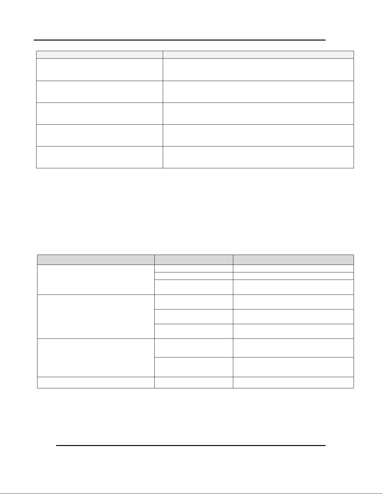
Capacity
Model RFD1-42-2E
Maximum load
(Lbs)
(KG)
200
91
Maximum shelf capacity
(Lbs)
(KG)
30
13.6
Models
Chamber Size
inches (cm)
Capacity
ft3 (liters)
Overall Size
inches (cm)
Maximum
number
of
Shelves
Exhaust
Outlet
Diameter
in (cm)
W D H W D
H
RFD
1-42-2E
20
(50.8)
18
(45.7)
20
(50.8)
4.2
(119)
46
(116.8)
36.5
(92.7)
37.5
(95.3)
8
1.75 x
2.75 (4.5 x
7.0)
Version 1 7
1.4. Conventions
1.5. Specifications
1.5.1. Dimensions
1.5.2. Capacities
All rights reserved. No part of the contents of this manual may be reproduced, copied or transmitted in any form or by any
means including graphic, electronic, or mechanical methods or photocopying, recording, or information storage and
retrieval systems without the written permission of Despatch Industries, unless for purchaser's personal use.
Copyright © 2012 by Despatch Industries.
Page 8
ABOUT THIS MANUAL RFD1-42-2E Oven Owner’s Manual
Capacity
Model RFD1-42-2E
Exhaust at 177°C (350°F)
(CFM)
(H.P.)
23 to 93 (10.9 - 43.9 lps)
1/50
Recirculating fan
(CFM)
425 (200 lps)
(H.P.)
1/2
Net weight (Approximate)
(Lbs)
380
(KG)
172
Shipping weight (Approximate)
(Lbs)
510
(KG)
231
Solvent Handling Capabilities at 177ºC
(350ºF)
(GPH of M.E.K)
0.025 (0.095 LPH)
Feature
Range
Model RFD1-42-2E
Time to Temperature
Minutes
(No Load)
40°C – 177°C
12
40°C – 260°C
24
40°C – 343°C
43
Recovery Time Door Open 1 min.
100°C
<1
200°C
2
343°C
4
Cooling Time to Temperature
Minutes
(No Load)
343°C – 50°C
46
343°C – 75°C
110
Temperature
177°C
+/- 2.3° C
8 Version 1
1.5.3. Temperatures
All rights reserved. No part of the contents of this manual may be reproduced, copied or transmitted in any form or by any
means including graphic, electronic, or mechanical methods or photocopying, recording, or information storage and
retrieval systems without the written permission of Despatch Industries, unless for purchaser's personal use.
Copyright © 2012 by Despatch Industries.
Page 9
RFD1-42-2E Oven Owner’s Manual ABOUT THIS MANUAL
Feature
Range
Model RFD1-42-2E
Uniformity at*
260°C
+/- 3.4° C
343°C
+/- 4.2° C
Minimum Operating Temperature
(approximate w/20°C Ambient)
Dampers Open
40°C
Dampers Closed
50°C
Control Stability (∆ represents the
change in ambient temperature)
+/- 0.5ºC/5ºC ∆
Repeatability
+/- 0.5ºC
*
†
Model
Volts†
Amps
Hertz
Heater Phase
KW
RFD1-42-2E
240
30.8
50/60 1 6
RFD1-42-2E
208
34.5
50/60 1 6
Version 1 9
1.5.4. Power
Line voltages may vary in some geographies. If the line voltage for your RFD1-42-2E oven varies
more than 10% from the oven voltage rating, electrical components such as relays and
temperature controls may operate erratically.
If the line voltage is lower than the oven voltage rating, heat-up time may be significantly
longer and motors may overload or run hot.
If the line voltage is higher than the nameplate rating, motors may run hot and draw excessive
amperage.
Uniformity figures are based on a nine-point test conducted in an empty oven after stabilization period.
Uniformity can vary slightly depending on unit and operating conditions. Minimum operating temperature
and cooling times are based on 20ºC ambient temperature measured at the fresh air inlet with the fresh air
and exhaust dampers fully open. Specifications are subject to change without notice.
An oven designed for 240 volts (see oven nameplate) will operate satisfactorily on a minimum of 208
Volts, but will result in 25% reduced heater output. If your power characteristic is lower, contact Despatch
Industries.
All rights reserved. No part of the contents of this manual may be reproduced, copied or transmitted in any form or by any
means including graphic, electronic, or mechanical methods or photocopying, recording, or information storage and
retrieval systems without the written permission of Despatch Industries, unless for purchaser's personal use.
Copyright © 2012 by Despatch Industries.
Page 10
ABOUT THIS MANUAL RFD1-42-2E Oven Owner’s Manual
Danger!
Class A ovens are designed for a specific amount of solvent.
Exceeding this amount could result in an explosion. Do not
process closed containers of any substance or liquid in this
oven because they may explode under heat. In case of fire, leave
door(s) as they are. Shut off electricity. Shut off fuel. Call the fire
department. Stay away.
10 Version 1
1.5.5. Capability
The RFD1-42-2E oven is specifically designed for Class A NFPA 86 requirements in which
flammable solvents are present. They include a pressure relief panel, purge timer and exhaust fan.
Please note the solvent handling capabilities and do not exceed those capabilities.
All rights reserved. No part of the contents of this manual may be reproduced, copied or transmitted in any form or by any
means including graphic, electronic, or mechanical methods or photocopying, recording, or information storage and
retrieval systems without the written permission of Despatch Industries, unless for purchaser's personal use.
Copyright © 2012 by Despatch Industries.
Page 11
RFD1-42-2E Oven Owner’s Manual SAFETY
Danger!
An accidental start-up, while working on the RFD1-42-2E oven,
can result in serious injury or death.
Danger!
Electrical panels contain high voltage. Disconnect and lock out
the power supply before working inside any electrical panels.
Failure to lock out the power supply can result in death or injury.
Version 1 11
2. Safety
2.1. Safety Information
Do not work on the RFD1-42-2E oven without reading and understanding this section which
contains important information and warnings. Ignoring these warnings can result in death, serious
injury or damage to the machine and product.
2.1.1. Lockout
Machine lockout places the RFD1-42-2E oven into a zero energy state and prevents accidental
machine start up. Always follow the Lockout Procedure described in this section before cleaning,
maintaining or repairing the RFD1-42-2E oven.
2.1.1.1. Lockout Requirements
1. Every power source that can energize any element of the RFD1-42-2E oven must be shut off
at the closest possible power source. This includes air, water, electricity, and the Disconnect
Switch (if applicable).
2. After energy sources are locked out, test to ensure circuits are de-energized.
2.1.1.2. Lockout Procedure
Personnel authorized to lockout equipment must have the necessary locks to perform the lockout.
1. Physically disconnect all electrical power to the machine or lockout the appropriate breaker
or disconnects.
2. Close all valves and bleed off any pressure.
3. Test for power by attempting a start with the machine controls.
4. Identify the Lockout Condition with a tag on the electrical disconnect and pneumatic shut off
valve.
5. When work is complete, remove all tags and restore the machine to its working state.
All rights reserved. No part of the contents of this manual may be reproduced, copied or transmitted in any form or by any
means including graphic, electronic, or mechanical methods or photocopying, recording, or information storage and
retrieval systems without the written permission of Despatch Industries, unless for purchaser's personal use.
Copyright © 2012 by Despatch Industries.
Page 12
SAFETY RFD1-42-2E Oven Owner’s Manual
Danger!
Contact with energized electrical sources may result in serious
injury or death.
Danger!
Always disconnect all power before extinguishing a fire.
Attempting to extinguish a fire in a machine connected to
electrical power can result in serious injury or death.
12 Version 1
2.2. Maintenance
Only qualified and trained personnel should perform maintenance or repair.
2.3. Electrical Power
Only qualified and trained personnel should perform electrical maintenance or electrical repair.
Before performing maintenance, disconnect all electrical power from the machine. Use a
padlock and lockout all disconnects feeding power to the machine.
Never clean or repair the oven when in operation.
Unauthorized alterations or modifications to RFD1-42-2E oven are strictly forbidden. Never
modify any electrical circuits. Unauthorized modifications can impair the function and safety
of the RFD1-42-2E oven.
2.4. Fire
Keep the RFD1-42-2E oven clean and free of scrap materials, oil or solvents to prevent the
possibility of fire.
1. Leave door as is.
2. De-energize the machine immediately by turning OFF the DISCONNECT SWITCH (if
applicable).
3. Turn off the remote main disconnect (customer supplied disconnect).
4. Shut off fuel.
5. Call the fire department.
6. Stay away.
2.5. Equipment Lockout Requirements
To prevent injury or equipment damage during inspection or repair, the RFD1-42-2E oven must
be locked out.
All rights reserved. No part of the contents of this manual may be reproduced, copied or transmitted in any form or by any
means including graphic, electronic, or mechanical methods or photocopying, recording, or information storage and
retrieval systems without the written permission of Despatch Industries, unless for purchaser's personal use.
Copyright © 2012 by Despatch Industries.
Page 13

RFD1-42-2E Oven Owner’s Manual SAFETY
Figure 1. Disconnect
Switch.
Version 1 13
2.5.1. Optional Disconnect Switch
The RFD1-42-2E oven has an optional Disconnect Switch (Figure 1). This
Disconnect Switch is located on the front of the oven and connected to the
load break switch behind the panel that disconnects or connects power from
the main line. When a risk of personal injury or damage to the RFD1-42-2E
oven exists, turn off the Disconnect Switch. This shuts off all electrical power
to the oven.
Copyright © 2012 by Despatch Industries.
All rights reserved. No part of the contents of this manual may be reproduced, copied or transmitted in any form or by any
means including graphic, electronic, or mechanical methods or photocopying, recording, or information storage and
retrieval systems without the written permission of Despatch Industries, unless for purchaser's personal use.
Page 14

THEORY OF OPERATION RFD1-42-2E Oven Owner’s Manual
Danger!
Class A ovens are designed for a specific amount of solvent.
Exceeding this amount could result in an explosion. Do not
process closed containers of any substance or liquid in this
oven because they may explode under heat. In case of fire, leave
door(s) as they are. Shut off electricity. Shut off fuel. Call the fire
department. Stay away.
Figure 2. RFD1-42-2E Oven.
14 Version 1
3. Theory of Operation
3.1. The RFD1-42-2E Oven
Despatch RFD1-42-2E ovens (Figure 2) are Class A
ovens specifically designed to meet NFPA 86
requirements. They effectively distribute heat and have
very fast processing times compared to other lab ovens
their size. Because of effective heat distribution and
fast processing times, the RFD1-42-2E ovens are
especially useful for testing, preheating, sterilizing,
drying, aging and curing, along with other production
applications. Horizontal airflow with precision digital
control delivers uniform, fast processing. The overall
result is efficient productivity under strenuous
conditions.
The unique Despatch computerized design moves
forced convected heat through perforated stainless steel
walls. The air is recirculated with a high volume fan. The Despatch RFD1-42-2E oven employs a
higher volume fan than competitive ovens, allowing dense loading of the chamber without
interfering with the process. The RFD1-42-2E oven maintains an air delivery temperature within
1/2ºC of the number appearing on the digital display. The oven regulates fresh air intake by a
damper slide located on the left side (Figure 3), and sets the exhaust rate by an adjustable control
on the exhaust stack.
The oven operator interface is located on the control panel to the right of the oven door (Figure
2). The RFD1-42-2E oven has a type 304 stainless steel interior and a scratch-resistant baked
enamel exterior. The interior cleans easily, and its construction reduces heat loss and aids in
maintaining temperature uniformity. The RFD1-42-2E oven comes with two shelves.
These Class A ovens are specifically designed to meet NFPA 86 requirements. They include a
pressure relief panel, purge timer and exhaust fan.
All rights reserved. No part of the contents of this manual may be reproduced, copied or transmitted in any form or by any
means including graphic, electronic, or mechanical methods or photocopying, recording, or information storage and
retrieval systems without the written permission of Despatch Industries, unless for purchaser's personal use.
Copyright © 2012 by Despatch Industries.
Page 15

RFD1-42-2E Oven Owner’s Manual THEORY OF OPERATION
Damper slide
Damper Control
Figure 3. RFD1-42-2E Oven Damper Control.
Notice
With the damper in full closed position, a predetermined amount of
fresh air enters the chamber via cutaways in the fresh air and exhaust
dampers. This amount of fresh air meets NFPA86 Safety Guidelines for
Class A ovens.
Version 1 15
3.2. Damper Control
The RFD1-42-2E oven comes with a manually adjustable damper mechanism which controls the
flow of fresh air into the chamber. The damper control is located on the left side of the oven
(Figure 3). The maximum amount of fresh air is distributed into the chamber when the damper is
in full open position. An additional adjustable damper is provided on the exhaust (Figure 4).
3.2.1. Determining Damper Settings
The optimum setting for the amount of fresh air that
should be distributed into the chamber depends on several
factors. These factors include ambient environment
temperature, load conditions, load distribution, heat-up
rates, cool-down rates, desired temperature uniformity
and, most importantly, the desired operating temperature.
Carefully consider existing engineering tradeoffs while
using guidelines to determine the fresh air damper setting.
In general, the damper should be set so that the amount of
fresh air flowing into the chamber agrees with the desired
operating temperature conditions. The following
paragraphs show the considerations involved with various
damper position settings.
3.2.1.1. Damper Full Closed Position
The chamber achieves maximum attainable heat-up rates when the fresh air damper lies in the full
closed position. With the damper in the full closed position, the chamber will operate at the
desired temperature using the minimum amount of power. In most cases, the oven also efficiently
operates at the chamber’s maximum operating temperature when in the full closed position.
3.2.1.2. Damper Full Open Position
The chamber operates at its minimum operating temperature with the fresh air damper in full
open position.
Friction heat from the air recirculation system builds up in the chamber. This causes chamber
temperature to rise slightly even without the heating system on. The chamber reaches thermal
equilibrium temperature after the recirculation motor runs for an extended period of time.
All rights reserved. No part of the contents of this manual may be reproduced, copied or transmitted in any form or by any
means including graphic, electronic, or mechanical methods or photocopying, recording, or information storage and
retrieval systems without the written permission of Despatch Industries, unless for purchaser's personal use.
Copyright © 2012 by Despatch Industries.
Page 16

THEORY OF OPERATION RFD1-42-2E Oven Owner’s Manual
Damper Control
When the damper is in full open position, the oven may not be
able to heat to the maximum oven operating temperature.
Figure 4. RFD1-42-2E Oven Exhaust
Damper Control
16 Version 1
The chamber cannot readily dissipate heat generated by friction without a fully open fresh air
damper. With the fresh air damper fully open, the thermal equilibrium temperature is the minimum operating temperature of the chamber.
3.2.1.3. Other Damper Settings
Damper settings can take distinct operating positions other than full closed or full open. In most
cases, uniformity and cool-down rates influence damper settings.
Chamber Uniformity
The system’s inside chamber pressure influences chamber uniformity. Pressure inside the
chamber depends on the amount of fresh air flowing into the chamber. When a large volume of
fresh air flows into the chamber, the chamber pressurizes slightly and overall temperature
uniformity improves. The slightly pressurized chamber produces the effect of "pushing" air to the
corners of the chamber. Typically the corners of the chamber improve with respect to temperature
distribution while the core of the chamber maintains excellent uniformity characteristics
regardless of damper position.
Pressurization of the chamber typically is a factor when the chamber is loaded heavily. The best
uniformity results, with respect to the product, are achieved when no more than two-thirds of any
inside chamber dimension are used. The best overall results are achieved when the product(s) are
located in the center of the chamber.
Cool-Down Rates
The more open the damper, the faster the cool-down.
3.2.1.4. Exhaust Damper Control
Adjusting the exhaust damper (Figure 4) aids in pressurizing
the chamber.
3.3. The Protocol 3 Controller
The Protocol 3™ controller is a microprocessor based digital
temperature controller designed for simple and flexible oven
operation (Figure 5). The Protocol 3 controller operates as a
dual-functioning controller/High Limit instrument. The control portion utilizes a time
proportioning voltage signal to control heating devices with minimal temperature fluctuations.
The High Limit portion protects the product and/or the oven from overheating. If the product
being processed has a critical high temperature limit, the High Limit setpoint should be set to a
temperature somewhat below the temperature at which the product could be damaged. If the
All rights reserved. No part of the contents of this manual may be reproduced, copied or transmitted in any form or by any
means including graphic, electronic, or mechanical methods or photocopying, recording, or information storage and
retrieval systems without the written permission of Despatch Industries, unless for purchaser's personal use.
Copyright © 2012 by Despatch Industries.
Page 17

RFD1-42-2E Oven Owner’s Manual THEORY OF OPERATION
Figure 5. Protocol 3 Operator Interface.
Version 1 17
product does not have a critical high temperature limit, the High Limit setpoint should be set 5 to
15 degrees higher than the maximum programmed setpoint at which the oven will operate.
The Protocol 3 controller provides three primary operating modes:
Manual: Oven operates continuously at a fixed temperature until turned off.
Timer: Oven operates at a fixed temperature for a user-selected time period, and then
automatically turns off.
Profile: Temperatures increase or decrease as defined by 255 segments that can be allocated
to 64 ramp and soak profiles. The profiles can be linked to provide additional temperature
combinations.
Review the Protocol 3 Controller Owner’s Manual for more information.
3.3.1. Optional High Limit Audible Alarm
High Limit audible and visual alarm is a red light and small alarm horn located on the front of the
control panel. The alarm is sounded if a High Limit condition occurs. A switch is provided to
silence the alarm. This alarm has a range of 80dB at 2 ft (0.6 m).
3.3.2. Optional Modbus Communications Hardware
RS485 Modbus communications are wired from the Protocol 3 controller to the DB9 connector
on the side of the oven. A programming manual is included which lists all the messages
recognized by the Protocol 3 controller. This manual is intended for those who will write their
own software. An RS232 to RS485 converter is required between the PC and a single oven. The
manual can also be used with Despatch Protocol Manager software.
Copyright © 2012 by Despatch Industries.
All rights reserved. No part of the contents of this manual may be reproduced, copied or transmitted in any form or by any
means including graphic, electronic, or mechanical methods or photocopying, recording, or information storage and
retrieval systems without the written permission of Despatch Industries, unless for purchaser's personal use.
Page 18

ASSEMBLY & SETUP RFD1-42-2E Oven Owner’s Manual
Danger!
Class A ovens are designed for a specific amount of solvent.
Exceeding this amount could result in an explosion. Do not
process closed containers of any substance or liquid in this
oven because they may explode under heat. In case of fire, leave
door(s) as they are. Shut off electricity. Shut off fuel. Call the fire
department. Stay away.
18 Version 1
4. Assembly & Setup
Assembly and Setup provides directions for unpacking and installing your RFD1-42-2E oven.
4.1. Unpack & Inspect The RFD1-42-2E Oven
Remove all packing materials and thoroughly inspect the oven for any damage that might have
occurred during shipment.
Note the condition of the carton and plastic cover sheet inside the carton.
Observe all outside surfaces and corners of the oven for scratches and dents.
Check oven controls and indicators for normal movement, bent shafts, cracks, chips or
missing parts such as knobs and lenses.
Check the door and latch for smooth operation.
4.1.1. If Damaged During Shipping
If damage occurred during shipping:
1. Contact the shipper immediately and file a written damage claim.
2. Contact Despatch Industries (1-800-473-7373 or 1-952-469-8230 or service@despatch.com)
to report your findings and to order replacement parts for those damaged or missing. Send a
copy of your filed damage claims to Despatch Industries (Despatch Industries, 8860 207th
Street, Lakeville, MN 555044, USA).
3. Check the packing list to ensure you received all the specified components of the oven
system. Contact Despatch Industries to have any missing products forwarded to you.
4. Complete the warranty card and mail it to Despatch within 15 days after receipt of the
equipment.
4.2. Setup The RFD1-42-2E Oven
4.2.1. Select Oven Location
The Despatch RFD1-42-2E oven is designed to operate in an industrial setting.
All rights reserved. No part of the contents of this manual may be reproduced, copied or transmitted in any form or by any
means including graphic, electronic, or mechanical methods or photocopying, recording, or information storage and
retrieval systems without the written permission of Despatch Industries, unless for purchaser's personal use.
Copyright © 2012 by Despatch Industries.
Page 19

RFD1-42-2E Oven Owner’s Manual ASSEMBLY & SETUP
Exhaust Port
Notice
Review oven weight to ensure the foundation is adequate to hold
the weight.
Warning!
Do not use the oven in wet, corrosive or explosive atmospheres
unless this oven is specifically designed for a special
atmosphere.
Figure 6. Exhaust Port on the Rear
Right of the RFD1-42-2E Oven.
Version 1 19
4.2.1.1. Single Oven Placement Requirements
Place oven on a solid foundation such as a bench top, an optional cabinet base, or directly on
the floor.
Allow at least two inches clearance at the rear of the oven to provide proper ventilation. The
oven may be placed next to another cabinet or next to another oven, with three-quarters of an
inch clearance. The doors will still open.
Plumb and level the oven to assure proper heat distribution and operation of all mechanical
components.
Do not expose oven to excessive vibration and affix all electrical cabinets.
If placing the oven in an area where excessive particulate matter exists (such as a construction
site or coal processing center), periodically clean all its electrical compartments. Keep the
power supply within the specifications provided by Despatch, and use a line conditioner for a
facility with an unstable power supply.
4.2.1.2. Multiple Oven Placement Requirement
Stack up to two ovens vertically, with or without the optional framework supplied by
Despatch.
Use the holes in the rear oven feet to bolt the ovens together by removing the hole plugs in
the top of the oven beneath.
4.2.2. Exhaust Connections
The RFD1-42-2E oven exhaust port is located on the rear
right of the oven (Figure 6). Install an exhaust stack from
the port to the outside of the building. Table 1 lists the
requirements for the exhaust stack for the RFD1-42-2E
oven.
All rights reserved. No part of the contents of this manual may be reproduced, copied or transmitted in any form or by any
means including graphic, electronic, or mechanical methods or photocopying, recording, or information storage and
retrieval systems without the written permission of Despatch Industries, unless for purchaser's personal use.
Copyright © 2012 by Despatch Industries.
Page 20

ASSEMBLY & SETUP RFD1-42-2E Oven Owner’s Manual
Requirements
RFD1-42-2E
Exhaust Outlet Rectangular Discharge
Opening Size
(in)
(cm)
1-3/4 x 2-3/4
4.4 x 7
Round Discharge Opening Size
Greater than area of exhaust stack (typically 3
inches diameter stack)
Flashing through roof or wall must be
capable of handling temperature of up to:
(ºC)
(ºF)
343
650
Notice
If more than two elbows are used in the stack, over all airflow
will be reduced. If airflow is reduced, the amount of solvent that
can be safely used with the equipment must also be reduced.
The oven must be hardwired directly to the electric supply.
Danger!
All grounding and safety equipment must be in compliance with
applicable codes, ordinances and accepted safe practices.
All stacks must comply with state and local building codes to
insure that surrounding combustible surfaces are below 71°C
(160°F).
20 Version 1
Table 1. Exhaust Connection Requirements.
4.2.3. Wiring & Power Connections
See electrical schematics in Section 8.3 for line connections.
All rights reserved. No part of the contents of this manual may be reproduced, copied or transmitted in any form or by any
means including graphic, electronic, or mechanical methods or photocopying, recording, or information storage and
retrieval systems without the written permission of Despatch Industries, unless for purchaser's personal use.
Copyright © 2012 by Despatch Industries.
Page 21

RFD1-42-2E Oven Owner’s Manual OPERATION
Users and operators of this oven must comply with operating
procedures and training of operating personnel as required by
the Occupational Safety and Health Act (OSHA) of 1970, Section
5 and relevant safety standards, and other safety rules and
regulations of state and local governments. Refer to the relevant
safety standards in OSHA and National Fire Protection
Association (NFPA), Section 86 of 1990.
Despatch Industries cannot be responsible for either the
process or process temperature used, or for the quality of the
product being processed. It is the responsibility of the
purchaser and operator to see that the product undergoing
processing in a Despatch oven is adequately protected from
damage.
Carefully following the instructions in this manual will help the
purchaser and operator in fulfilling that responsibility.
Caution!
Always place loads on the shelves provided to avoid possible
uneven heating and damage to the oven.
Danger!
Class A ovens are designed for a specific amount of solvent.
Exceeding this amount could result in an explosion. Do not
process closed containers of any substance or liquid in this
oven because they may explode under heat. In case of fire, leave
door(s) as they are. Shut off electricity. Shut off fuel. Call the fire
department. Stay away.
Version 1 21
5. Operation
5.1. Load Oven
Avoid spilling on the heater elements or oven floor when loading the oven. Do not place the load
on the oven floor plate. Placing the load on the oven floor may cause the load to heat unevenly,
and the weight may cause shorting out of the heater elements. Use the shelves provided.
All rights reserved. No part of the contents of this manual may be reproduced, copied or transmitted in any form or by any
means including graphic, electronic, or mechanical methods or photocopying, recording, or information storage and
retrieval systems without the written permission of Despatch Industries, unless for purchaser's personal use.
Copyright © 2012 by Despatch Industries.
Page 22

OPERATION RFD1-42-2E Oven Owner’s Manual
Danger!
This equipment is designed for a specific amount of solvent.
Exceeding this amount could result in explosion.
22 Version 1
The two shelves are designed to be pulled out about halfway without tipping. Do not overload the
shelves. Shelve support capacity is listed in the Capacities section (1.5.2). Do not overfill your
oven. Distribute the workload evenly so airflow is not restricted. The workload should not take
up more than two-thirds of any dimension of the inside cavity.
5.2. Pre-Startup Checklist
Know the system. Read this manual carefully and make use of its instructions and
explanations. Safe, continuous, satisfactory, and trouble-free operation depends primarily on
your degree of understanding of the system and your willingness to keep all parts in proper
operating condition.
Check line voltage. Voltage must correspond to nameplate requirements of motors and
controls. A wrong voltage can result in serious damage. Refer to Section 1.5.4 for more
information.
Check fresh air and exhaust openings. Do not be careless about restrictions in and around the
fresh air and exhaust openings and stacks. Refer to Sections 1.5.2 and 4.2.2 for information
on exhaust specifications and requirements. Under no condition can they be permitted to
become so filled with dirt that they reduce airflow.
For drying ovens, open the exhaust damper to prevent buildup of moisture.
For sample heating, close the exhaust damper when no ventilation is required.
All rights reserved. No part of the contents of this manual may be reproduced, copied or transmitted in any form or by any
means including graphic, electronic, or mechanical methods or photocopying, recording, or information storage and
retrieval systems without the written permission of Despatch Industries, unless for purchaser's personal use.
Copyright © 2012 by Despatch Industries.
Page 23

RFD1-42-2E Oven Owner’s Manual OPERATION
If your oven is equipped with a Disconnect Switch, turn it to
ON before starting the fan.
Notice
The heater of the Class A oven cannot be energized until the
forced exhaust system has brought in a minimum amount of
fresh air into the chamber. The purge timer provided prevents
the heater from energizing until the oven has had enough time
to bring in the required amount of fresh air. The airflow switch,
which closes when the exhaust system is running, energizes
the purge timer. The predetermined purge time for the RFD1-422E is two minutes.
Version 1 23
5.3. Operating Procedure
5.3.1. Start Oven
For fastest oven heat-up time, close the fresh-air vent. After reaching the desired temperature,
adjust the vent as needed.
1. Start the fan.
a. Open oven door.
b. Set POWER to ON. You will hear the sound of the recirculating fan starting.
c. Shut oven door.
d. Check that the control display turns ON.
2. Operate the temperature control as desired.
5.3.2. Working with Protocol 3 Operating Modes
Refer to the Protocol 3 Controller Owner’s Manual for specific information on working with the
controller.
All rights reserved. No part of the contents of this manual may be reproduced, copied or transmitted in any form or by any
means including graphic, electronic, or mechanical methods or photocopying, recording, or information storage and
retrieval systems without the written permission of Despatch Industries, unless for purchaser's personal use.
Copyright © 2012 by Despatch Industries.
Page 24

MAINTENANCE RFD1-42-2E Oven Owner’s Manual
Danger!
Disconnect all power sources before making repairs. Contact
with energized electrical sources may result in serious injury or
death.
24 Version 1
6. Maintenance
Do not attempt any service on this oven before opening the main power Disconnect Switch.
6.1. Checklist
Keep equipment clean. Gradual dirt accumulation retards airflow. A dirty oven can result in
unsatisfactory operation such as unbalanced temperature in the work chamber, reduced
heating capacity, reduced production, overheated components, and the like. Keep the walls,
floor and ceiling of the oven work chamber free of dirt and dust. Floating dust or accumulated
dirt may produce unsatisfactory work results.
Keep all equipment accessible. Do not permit other materials to be stored or piled against it.
Protect controls against excessive heat—particularly controls, motors or other equipment
containing electronic components. Avoid temperatures greater than 51.5°C (125°F).
Establish maintenance and checkup schedules. Do this promptly and follow the schedules
faithfully. Careful operation and maintenance will be more than paid for in continuous, safe
and economical operation.
Maintain equipment in good repair and make repairs immediately to avoid costly delays
Practice safety. Make it a prime policy to know what you are doing before you do it. Make
caution, patience, and good judgment the safety watchwords for the operation of your oven.
6.2. Test Airflow Switch and Purge Timer
The airflow switch and purge timer should be tested every 40 hours. To test the airflow switch
and purge timer:
1. Allow the oven to stabilize at its minimum operating temperature by turning the heater off.
Place all dampers in the closed position.
2. Cycle power to the system.
3. The airflow switch should be closed, but the heater relay should remain de-energized until the
purge timer times out. This can be verified by monitoring the purge timer.
Indicators 1LED and 2LED should be lit. 3LED should remain off until the purge timer times out.
All rights reserved. No part of the contents of this manual may be reproduced, copied or transmitted in any form or by any
means including graphic, electronic, or mechanical methods or photocopying, recording, or information storage and
retrieval systems without the written permission of Despatch Industries, unless for purchaser's personal use.
Copyright © 2012 by Despatch Industries.
Page 25

RFD1-42-2E Oven Owner’s Manual MAINTENANCE
Danger!
Disconnect and lock out the power supply before opening the
panel to test the airflow switch and purge timer or work with the
circuit board. Failure to lock out the power supply can result in
death or injury.
Indicator LED’s
Neutral Terminal 2
4L1, 1H2 & 1H1 Connections
2 & 3F Fuse blocks
1F& 4F Fuse blocks
Power Terminal Block
Purge Timer socket
1LED
2LED
3LED
Version 1 25
Figure 7. RFD1-42-2E Circuit Board.
6.3. Lubrication
Fan motor bearings are permanently lubricated. Lubricate all door latches, hinges, door operating
mechanisms, bearings and wear surfaces to ensure easy operation.
6.4. Replacement Parts
Contact the Service Products Division at Despatch to order or return parts. The Service Products
features our Response Center for customer service. When returning parts, a Despatch
representative will provide you with an MRA (Material Return Authorization) number, which
must be attached to the returned part for identification. When ordering a replacement part, be sure
to give the model number, serial number, and part number to expedite the process. Contact the
Global Service Network at 1-800-473-7373 with any service needs.
All rights reserved. No part of the contents of this manual may be reproduced, copied or transmitted in any form or by any
means including graphic, electronic, or mechanical methods or photocopying, recording, or information storage and
retrieval systems without the written permission of Despatch Industries, unless for purchaser's personal use.
Copyright © 2012 by Despatch Industries.
Page 26

MAINTENANCE RFD1-42-2E Oven Owner’s Manual
Danger!
Disconnect all power sources before making repairs. Contact
with energized electrical sources may result in serious injury or
death.
Danger!
Disconnect all power sources before making repairs. Contact
with energized electrical sources may result in serious injury or
death.
26 Version 1
6.5. Repairs
6.5.1. Protocol 3 Controller
Refer to the Protocol 3 Owner’s Manual for instructions on replacing the Protocol 3 controller.
6.5.2. Heater Unit
Follow these guidelines to repair the RFD1-42-2E oven heater unit if necessary. Required tools:
3/8# wrench
Square recess driver with #1 bit
Directions:
1. Disconnect power.
2. Remove left and right inside walls.
3. Remove chamber floor plate from oven.
4. Disconnect heater leads from heater element with wrench. Note which wires go on which
terminals.
5. Unscrew screws holding heater frame to oven body.
6. Remove heater and discard.
7. Screw down new heater frame.
8. Attach heater leads to appropriate terminals.
9. Replace interior floor.
10. Replace inside walls.
6.5.3. Fan Motor
Follow these guidelines to repair the RFD1-42-2E oven fan motor if necessary. Required tools:
Screwdriver
5/32 inch Allen wrench
One quarter (¼) inch socket set
All rights reserved. No part of the contents of this manual may be reproduced, copied or transmitted in any form or by any
means including graphic, electronic, or mechanical methods or photocopying, recording, or information storage and
retrieval systems without the written permission of Despatch Industries, unless for purchaser's personal use.
Copyright © 2012 by Despatch Industries.
Page 27

RFD1-42-2E Oven Owner’s Manual MAINTENANCE
Danger!
Disconnect all power sources before making repairs. Contact
with energized electrical sources may result in serious injury or
death.
3
Version 1 27
Directions:
1. Remove left and right inside walls.
2. Remove chamber floor plate from oven.
3. Remove fan inlet plate.
4. Loosen set screws (2) on fan wheel.
5. Remove side access panel. This will reveal the fan motor.
6. Remove fan motor.
a. Disconnect motor leads from circuit board.
b. Remove screws (4) holding the motor to the base.
c. Lift fan motor from oven body.3
7. Replace fan motor.
a. Insert shaft into shaft collar. Put fan wheel onto shaft from inside oven.
b. Reattach motor to motor base.
c. Reattach motor lead wires to circuit board.
8. Adjust fan wheel for 3/16 inch clearance between wheel and inlet ring.
9. Tighten set screws on fan wheel.
10. Check that the set screws hit the flats machined into the motor shaft.
11. Replace chamber floor plate.
12. Replace left and right side walls.
13. Replace side access panel.
After the fan wheel has run at temperature for a while, it will stick to the shaft. Some force may be
required to separate the fan wheel from the fan motor shaft.
All rights reserved. No part of the contents of this manual may be reproduced, copied or transmitted in any form or by any
means including graphic, electronic, or mechanical methods or photocopying, recording, or information storage and
retrieval systems without the written permission of Despatch Industries, unless for purchaser's personal use.
Copyright © 2012 by Despatch Industries.
Page 28

TROUBLESHOOTING RFD1-42-2E Oven Owner’s Manual
Difficulty
Probable Cause
Suggested Remedy
Failure to heat or
heats up to only
35-50C
No power
Burned out heater
Broken or frayed cord
Protocol 3 controller
malfunction
Loose wire connections
Heater relay failure
Door switch failure (if
installed)
Check power source and/or oven and wall
fuses.
Replace heater (see Warranty, Section 8.1).
Replace with new cord.
Replace Protocol 3 controller.
Disconnect power and check connections behind control panel.
Replace circuit board.
Replace door switch.
Slow heat up
Improperly loaded
Low line voltage
Heating element(s) are
burned out
240 volt oven is connected
to a 208V line
Fan motor failure
Reduce load or redistribute load in chamber.
Supply sufficient power and proper
connections. Check for circuit overload.
Replace heater (see Warranty, Section 8.1).
Raise line voltage to a 240 volt line or modify
oven for 208V operation (consult factory).
Replace fan motor.
Frequent heater
element burnout
Harmful fumes generated by
load
Spillage or splattering of
material on heater elements
Overheating oven
Increase vent opening or discontinue process.
Disconnect power and clean oven chamber
and elements.
Check the High Limit.
28 Version 1
7. Troubleshooting
7.1. Possible Problems and Suggested Solutions
Equipment which operates for long periods of time may develop problems. Table 2 lists possible
problems and suggested solutions. If you have a problem not listed and a question about how to
handle it, contact Despatch Industries at our toll free Help Line: 800-473-7373.
Table 2. Possible Problems and Suggested Solutions.
All rights reserved. No part of the contents of this manual may be reproduced, copied or transmitted in any form or by any
means including graphic, electronic, or mechanical methods or photocopying, recording, or information storage and
retrieval systems without the written permission of Despatch Industries, unless for purchaser's personal use.
Copyright © 2012 by Despatch Industries.
Page 29

RFD1-42-2E Oven Owner’s Manual TROUBLESHOOTING
Difficulty
Probable Cause
Suggested Remedy
Erratic temp. or
inaccurate temp
Protocol 3 controller
malfunction
Improper tuning parameters
Protocol 3 controller
miscalibration
High Limit setting
Improper offset
Replace Protocol 3 controller.
Check tuning parameters.
Recalibrate Protocol 3 controller (see Protocol
3 Controller Owner’s Manual for further
instruction).
High Limit should be 10-25ºC higher than
setpoint.
Check zone calibration.
Excess surface or
door temp.
Door seal deterioration
Replace door seal.
Improper airflow
Fan motor failure
Fan wheel seated too low on
fan shaft
Unbalanced fan wheel
Replace fan motor.
Adjust fan wheel for 3/16" clearance between
wheel and inlet ring.
Replace fan wheel.
Excessive
vibration
Dirty fan wheel
Unbalanced fan wheel
Clean fan.
Replace fan wheel.
Oven will not
control at setpoint
High Limit set too low
Protocol 3 controller
malfunction
SSR malfunction
Air friction of recirculation fan
Set the High Limit higher.
Replace Protocol 3 controller.
Replace SSR and/or check control output
voltage.
Open exhaust air vent. Unit will not control
below minimum operating temperature with
vent closed.
Heater does not
shut down until
temp. reaches the
High Limit setting
Protocol 3 controller
malfunction
SSR malfunction
Replace Protocol 3 controller.
Replace SSR.
Version 1 29
All rights reserved. No part of the contents of this manual may be reproduced, copied or transmitted in any form or by any
means including graphic, electronic, or mechanical methods or photocopying, recording, or information storage and
retrieval systems without the written permission of Despatch Industries, unless for purchaser's personal use.
Copyright © 2012 by Despatch Industries.
Page 30

TROUBLESHOOTING RFD1-42-2E Oven Owner’s Manual
If LED is…
Check…
1 LED
2LED
3 LED
Not Lit
Check Fuse Block 2F and 3F (Figure 7)
Lit
Not lit
Lit
Check High Limit
Check optional door switch, if appropriate
Lit
Lit
Lit
Check Fuse Block 1F and 4F (Figure 7)
Check SSR
Check heater
Check heater relays
Danger!
Electrical panels contain high voltage. Disconnect and lock out
the power supply before working inside any electrical panels.
Failure to lock out the power supply can result in death or injury.
Alarm Status
Possible Problem
Next Step
HI LIMIT LED ON
Problem with thermocouple
High Limit setpoint has been
exceeded
Once the problem has corrected,
press RESET.
DEV HOLD LED flashing
Oven temperature has not
entered (or dropped out of) the
Auto Hold band and the soak
timer has stopped
Program a slower ramp rate or, if
oven is not heating check heater
circuit.
Top PV displays OPEN
Control thermocouple is
disconnected or broken
Repair or replace the thermocouple.
HLPV displays OPEN
High Limit thermocouple is
disconnected or broken
Repair or replace the thermocouple.
Danger!
Table 3 lists troubleshooting steps that must be performed by a
qualified electrician or electrical technician trained on electrical
safety and the use of personal protective equipment.
30 Version 1
Table 3. Troubleshooting with Control Panel Mounted Circuit Board.
7.2. Error Messages and Alarm
Table 4 lists the more common error messages, possible problems and remedies.
Table 4. Error Messages and Next Steps.
All rights reserved. No part of the contents of this manual may be reproduced, copied or transmitted in any form or by any
means including graphic, electronic, or mechanical methods or photocopying, recording, or information storage and
retrieval systems without the written permission of Despatch Industries, unless for purchaser's personal use.
Copyright © 2012 by Despatch Industries.
Page 31

RFD1-42-2E Oven Owner’s Manual APPENDICES
Version 1 31
8. Appendices
8.1. Standard Products Warranty
All rights reserved. No part of the contents of this manual may be reproduced, copied or transmitted in any form or by any
Copyright © 2012 by Despatch Industries.
means including graphic, electronic, or mechanical methods or photocopying, recording, or information storage and
retrieval systems without the written permission of Despatch Industries, unless for purchaser's personal use.
Page 32

APPENDICES RFD1-42-2E Oven Owner’s Manual
Refer to instructions provided by the recorder manufacturer for
more specific installation notes.
Parameter Code
Degrees C
Degrees F
Inps
17
17
Icor 0 0
diSP
On
On
dPOS
0 0 EUU4
400
752
EUL4
0
32
ChUP
400
8005
ChLO
0 0 DFF
1
1
4
5
32 Version 1
8.2. MRC5000 Setup (Optional)
Temperature is retransmitted to the MRC5000 recorder from the controller. To set up the
recorder:
1. Ensure hardware jumper JU1 is in place for the 5 VDC setting (Refer to MRC5000 Manual
included).
2. Move MODE to PROG/TEST/CAL to display Prog.
3. Press ▼ twice to display Inps. Move to each Parameter Code using ▼or ▲. Adjust each
Parameter Code using the settings in Table 5.
4. After adjusting all settings, move MODE to RUN. Display on both the recorder and controller
should read the same.
Table 5. MRC 5000 Settings.
8.3. Electrical Schematics
The following pages contain electrical schematics for the RFD1-42-2E oven.
These values must match the settings RetOutLo and RetOutHi on the Protocol 3 Control page. For
example, if RetOutLo is 32, EUL must read 32.
Change 0-400 chart paper to 0-800 chart paper. Depending on the equipment, 0-600 paper may be used if
the maximum temperature is 500ºF.
All rights reserved. No part of the contents of this manual may be reproduced, copied or transmitted in any form or by any
means including graphic, electronic, or mechanical methods or photocopying, recording, or information storage and
retrieval systems without the written permission of Despatch Industries, unless for purchaser's personal use.
Copyright © 2012 by Despatch Industries.
Page 33

RFD1-42-2E Oven Owner’s Manual APPENDICES
Figure 8. RFD1-42-2E (Drawing 320214-01).
Version 1 33
All rights reserved. No part of the contents of this manual may be reproduced, copied or transmitted in any form or by any means including graphic, electronic, or mechanical methods
or photocopying, recording, or information storage and retrieval systems without the written permission of Despatch Industries, unless for purchaser's personal use.
Copyright © 2012 by Despatch Industries.
Page 34

APPENDICES RFD1-42-2E Oven Owner’s Manual
Figure 9. RFD1-42-2E (Drawing 320214-02).
34 Version 1
All rights reserved. No part of the contents of this manual may be reproduced, copied or transmitted in any form or by any means including graphic, electronic, or mechanical methods
or photocopying, recording, or information storage and retrieval systems without the written permission of Despatch Industries, unless for purchaser's personal use.
Copyright © 2012 by Despatch Industries.
Page 35

RFD1-42-2E Oven Owner’s Manual APPENDICES
Figure 10. RFD1-42-2E (Drawing 320214-03).
Version 1 35
All rights reserved. No part of the contents of this manual may be reproduced, copied or transmitted in any form or by any means including graphic, electronic, or mechanical methods
or photocopying, recording, or information storage and retrieval systems without the written permission of Despatch Industries, unless for purchaser's personal use.
Copyright © 2012 by Despatch Industries.
Page 36

APPENDICES RFD1-42-2E Oven Owner’s Manual
Figure 11. RFD1-42-2E (Drawing 320215-01).
36 Version 1
All rights reserved. No part of the contents of this manual may be reproduced, copied or transmitted in any form or by any means including graphic, electronic, or mechanical methods
or photocopying, recording, or information storage and retrieval systems without the written permission of Despatch Industries, unless for purchaser's personal use.
Copyright © 2012 by Despatch Industries.
Page 37

RFD1-42-2E Oven Owner’s Manual APPENDICES
Figure 12. RFD1-42-2E (Drawing 320215-02).
Version 1 37
All rights reserved. No part of the contents of this manual may be reproduced, copied or transmitted in any form or by any means including graphic, electronic, or mechanical methods
or photocopying, recording, or information storage and retrieval systems without the written permission of Despatch Industries, unless for purchaser's personal use.
Copyright © 2012 by Despatch Industries.
Page 38

APPENDICES RFD1-42-2E Oven Owner’s Manual
Figure 13. RFD1-42-2E (Drawing 320215-03).
38 Version 1
All rights reserved. No part of the contents of this manual may be reproduced, copied or transmitted in any form or by any means including graphic, electronic, or mechanical methods
or photocopying, recording, or information storage and retrieval systems without the written permission of Despatch Industries, unless for purchaser's personal use.
Copyright © 2012 by Despatch Industries.
Page 39

RFD1-42-2E Oven Owner’s Manual TROUBLESHOOTING
Version 1 39
3rdDraft—
All rights reserved. No part of the contents of this manual may be reproduced, copied or transmitted in any form or by any
Copyright © 2012 by Despatch Industries.
means including graphic, electronic, or mechanical methods or photocopying, recording, or information storage and
retrieval systems without the written permission of Despatch Industries, unless for purchaser's personal use.
 Loading...