

Page 1

C-200
RBC1
RBC1----50
RBC1RBC1
INSTRUCTION MANUAL
INSTRUCTION MANUAL
INSTRUCTION MANUALINSTRUCTION MANUAL
50
5050
PN 163189
REVISION B
1/2003
Page 2

Notice
Users of this equipment must comply with operating procedures and training of operation
personnel as required by the Occupational Safety and Health Act (OSHA) of 1970,
Section 6 and relevant safety standards, as well as other safety rules and regulations of
state and local governments. Refer to the relevant safety standards in OSHA and
National Fire Protection Association (NFPA), section 86 of 1990.
Caution
Setup and maintenance of the equipment should be performed by qualified personnel who
are experienced in handling all facets of this type of system. Improper setup and
operation of this equipment could cause an explosion that may result in equipment
damage, personal injury or possible death.
Dear Customer,
Thank you for choosing Despatch Industries. We appreciate
the opportunity to work with you and to meet your heat
processing needs. We believe that you have selected the
finest equipment available in the heat processing industry.
At Despatch, our service does not end after the purchase
and delivery of our equipment. For this reason we have
created the Service Products Division within Despatch. The
Service Products Division features our Response Center for
customer service. The Response Center will direct and track
your service call to ensure satisfaction.
Whenever you need service or replacement parts, contact
the Response Center at 1-800-473-7373: FAX 612-781-
5353.
Thank you for choosing Despatch.
Sincerely,
Despatch Industries
Page 3
Page 4
Page 5

PREFACE
This manual is your guide to the Despatch oven. It is organized to give you the
information you need quickly and easily.
The INTRODUCTION section provides an overview of
the Despatch oven.
The THEORY OF OPERATION section details the
function and operation of assemblies and
subassemblies on the Despatch oven.
The INSTRUCTIONS section provides directions on
unpacking, installing, operating and maintaining the
Despatch oven.
The APPENDIX section contains special instructions
on air atmosphere and nitrogen atmosphere Burn-In
ovens, a Troubleshooting Table, a list of Accessories
and a Warranty.
Refer to the manufacturer’s manual for instructions on the use of the controls.
The parts are listed in the corner of the prints, the electrical items on the electrical print
and the mechanical items on the mechanical prints.
An efficient way to learn about the oven would be to read the manual while working with
the corresponding oven control system. This will give you practical hands-on
experience with information in the manual and the oven.
Before operating the equipment, be sure you understand all of the technical information
contained in this manual. Information skipped, not understood or misunderstood could
create the possibility of operating the equipment in an unsafe manner. This can cause
damage to the oven or personnel or reduce the efficiency of the equipment.
NOTE:
Read the entire
INTRODUCTION and THEORY
OF OPERATION before
installing the oven.
WARNING:
Failure to heed warnings in this
instruction manual and on the
oven could result in personal
injury, property damage or
death.
1
Page 6

TABLE OF CONTENTS
PREFACE.......................................................................................................................1
INTRODUCTION.............................................................................................................4
Special Features..........................................................................................................4
Specifications ..............................................................................................................5
Dimensions ..............................................................................................................5
Capacities ................................................................................................................5
Temperature ............................................................................................................6
Power.......................................................................................................................7
Power Requirements............................................................................................7
THEORY OF OPERATION .............................................................................................8
Temperature Control....................................................................................................8
Power Switch...............................................................................................................9
Air Circulation ..............................................................................................................9
Chamber Design..........................................................................................................9
Airflow Switch ..............................................................................................................9
Alarm...........................................................................................................................9
Chamber Door Handle...............................................................................................10
Damper Control ......................................................................................................... 10
Determining Damper Settings................................................................................10
Full Closed Position............................................................................................10
Full Open Position.............................................................................................. 11
Minimum Opening for Dissipation of Live Load ..................................................11
Other Damper Settings.......................................................................................11
OVEN INSTRUCTIONS................................................................................................13
Unpacking and Inspection .........................................................................................13
Warning Signs Missing..............................................................................................14
Set-up........................................................................................................................15
Power Connection ..................................................................................................... 16
Operating...................................................................................................................17
Loading the Oven...................................................................................................17
Oven Temperature Limit ........................................................................................18
Product Temperature Limit.....................................................................................18
Operator Training Requirements............................................................................18
Pre-Startup Checklist.............................................................................................19
Startup ...................................................................................................................19
Maintenance..............................................................................................................21
Checklist ................................................................................................................21
Inspection and Cleaning.........................................................................................22
Vents..................................................................................................................22
Chamber.............................................................................................................22
Control Cabinet and Fan ....................................................................................22
Chamber Door Gasket........................................................................................23
Recirculation Motor.............................................................................................23
Oven Exterior......................................................................................................23
Oven Chamber Interior.......................................................................................23
Door Hinges and Latches...................................................................................23
2
Page 7

Automatic Damper..............................................................................................24
Controls and Indicators.......................................................................................24
Loose Screws, Bolts and Fasteners ...................................................................24
Lubrication..........................................................................................................24
Tests...................................................................................................................... 25
OPTIONAL ACCESSORIES .........................................................................................26
Door Switch ............................................................................................................... 26
Recorder....................................................................................................................26
Redundant High-Limit................................................................................................26
Disconnect Switch ..................................................................................................... 27
Stacking Option ......................................................................................................... 27
Replacement .............................................................................................................28
Parts.......................................................................................................................28
Nitrogen and Liquid Nitrogen.....................................................................................28
Theory of Operation...............................................................................................28
Operator Training Requirements............................................................................29
Operation...................................................................................................................29
Nitrogen Atmosphere.................................................................................................31
Purge Rate.............................................................................................................31
Maintain Rate.........................................................................................................32
Troubleshooting.........................................................................................................33
Circuit Board Check...............................................................................................35
3
Page 8

INTRODUCTION
This instruction manual covers the operation and
maintenance of the Despatch RBC1-50 Burn-In
oven.
NOTE:
Read the entire
INTRODUCTION and THEORY
OF OPERATION before
installing the oven.
Special Features
The sturdy construction and three-inch insulation top and bottom and four-inches of
insulation on the sides of the Despatch RBC1-50 Burn-In ovens contribute to excellent
temperature uniformity.
Other special features include the following:
• Unique Despatch design to combine higher fan volume of forced recirculated air
with a system of perforated stainless steel walls for the ultimate in temperature
uniformity.
• Welded double wall construction and fiberglass insulation to reduce heat loss.
Silicone rubber gaskets further minimize heat leakage.
• Rapid response heater.
• Scratch-resistant baked enamel exterior and stainless steel interior for easy
cleaning.
4
Page 9
Specifications
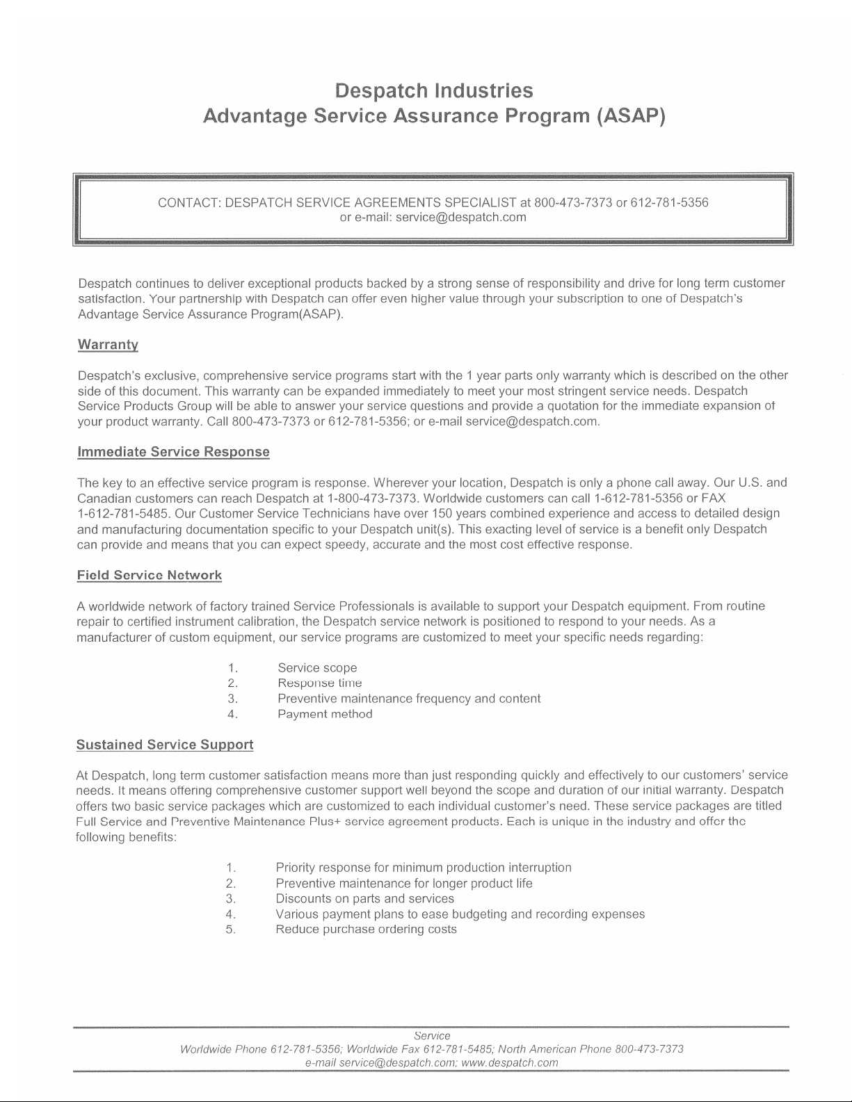
Dimensions
Model Chamber Size
in (cm)
W D H W D H
RBC1-50 18
(46)
25
(64)
(46)
Capacities
Maximum Load 150 Lbs
Fresh Air/ Exhaust Capacity at
125 °C (255 °F)
Recirculating Fan 600 CFM 1 HP
Capacity
feet3
(liters)
18
4.7
(133)
RBC1-50
Air Atmosphere
51 CFM N/A
Overall Size
in (cm)
46
(117)
36
(91)
MODEL
RBC1-50
Nitrogen Atmosphere
31.50
(80)
Fresh Air Inlet 2.5” Diameter N/A
Exhaust outlet 2.18” Diameter N/A
# of Doors 1
Approximate Weight 470 Lbs. (213 KG)
5
Page 10

Temperature
RBC1-50
Time to Temperature 25°C - 80°C
(approximate minutes with 25°C - 125°C
no live load)
25°C - 260°C
Recovery Time to 125°C with door open 1 Min.
Temperature Uniformity at
260°C*
Operating Temperature Range
(Based on 25°C ambient, and dampers fully open)
(1)
25°C - 150°C
(2)
125°C*
RBC1-50
Air Atmosphere
4
10
14
34
>1 Min. >1 Min.
<±1°C
±1°C
50° - 260°C 15° - 260°C
Nitrogen Atmosphere
4
10
14
30
<±1°C
±1°C
Control Stability
Repeatability ±0.5°C
Cooldown Time 125° - 60°C
Dissipation/Mean Temperature Rise
125°C
150°C
(1)
Time to temperature will be slightly longer for lower voltages due to heater kW derating (empty oven).
(2)
Figures are based on a nine-point survey in an empty oven. Uniformity can vary slightly depending
on unit and operating conditions.
(3)
∆
In control stability figures represent the change in ambient temperature.
(4)
Dissipation is reduced by 17% on 50-Hertz operation. Temperature gradient/mean temperature rise is
with an evenly distributed live load.
(3)
40 Min. 11 Min.
(4)
80°C
±0.5°C per 5°C ∆
800 Watts/4°C
1,300 Watts/6°C
1,400 Watts/6°C
Note: Testing performed on 240V-1PH-60HZ.
6
Page 11

Power
Line voltages may vary in some geographical locations.
If your line voltage is much lower than the oven voltage
rating, warm up time will be longer and motors may
overload or run hot. If your line voltage is higher than
nameplate rating, the motor may run hot and draw
excessive amps.
If the line voltage varies more than 10% from the oven
voltage rating, some electrical components such as
relays, temperature controls, etc. may operate
erratically.
Power Requirements
WARNING:
All grounding and safety
equipment must be in compliance
with applicable codes, ordinances
and accepted safe practices.
WARNING:
Failure to read this warning
can result in death, serious
bodily injury or property
damage. All conductors
must be copper unless the
specific terminal is marked
for use with aluminum
conductors.
Volts Amps Hertz Phase Heater KW
208 23 60 1 3
220 24 50 1 3.4
240 24 60 1 4
7
Page 12

THEORY OF OPERATION
Despatch RBC1-50 Burn-In ovens are made for the accelerated life testing of
microcircuit electronic devices to identify early mortality. The Despatch RBC1-50 ovens
are ideally suited for:
• high-dissipation forward-bias burn-in,
• high temperature reverse-bias burn-in,
• stabilization baking of integrated circuits and other semiconductor devices.
Air atmosphere ovens recirculate air through the chamber. They can add heat and
remove dissipated heat. Air is taken from the burn-in room and circulated through the
oven. Heat is added by electric resistance elements, or removed through automatically
controlled exhaust.
Temperature Control
A modular microprocessor based digital temperature controller regulates the process.
The control utilizes a time-proportioning voltage signal to control heating, and a milliamp
signal to control cooling with minimal temperature fluctuations.
The controller temperature-sensing element, located in the air return plenum area,
senses the median air temperature of the oven. The controller automatically controls
heat dissipated by sending a signal to the automatic damper modulator. This automatic
damper controls the amount of fresh air drawn into the chamber, preventing excessive
cooling and conserving energy.
The high limit control protects the product and/or the oven from overheating. If the
product being processed has a critical high temperature limit, the high limit setpoint
should be set to a temperature somewhat below the temperature at which the product
could be damaged. If the product does not have a critical high temperature limit, the
high limit setpoint should be set 5 to 15 degrees higher than the maximum-programmed
setpoint at which the oven will operate. When the high limit trips, the alarm horn will
sound.
Please refer to the manufacturer’s manual on the control and high limit.
8
Page 13

Power Switch
The POWER switch controls power to the control circuit, chamber recirculating fan
motor relay, control cabinet fan, and any options that were included at the time of
purchase.
Air Circulation
A Despatch centrifugal fan draws air through the heater section, moves it evenly across
the chamber, past the temperature sensors and back to the heater. The fresh air is
controlled manually and a modulating damper controls the exhaust.
Chamber Design
The chamber (in which the load is processed) has air supply and exhaust ducts on
opposite sides. The ducts and perforated panels provide uniform airflow and
temperature distribution throughout the chamber.
Airflow Switch
The airflow switch senses the differential pressure between the inlet and outlet side of
the recirculating fan. If there is no air pressure, the switch disconnects power to the
heater, and the alarm horn will signal. An On/Off indicator is visible through a window
on the switch. The switch is located in the upper equipment compartment, behind the
equipment panel and next to the recirculating motor.
Alarm
When there is a high limit condition, or when there is no air pressure sensed by the
airflow switch, an alarm will sound and a red pilot light will be lit. To silence the alarm,
depress the momentary ALARM SILENCE switch. The red light will remain on until the
alarm condition is cleared.
9
Page 14

Chamber Door Handle
The door handle positively engages a cam with a catch in one-quarter turn. The
silicone rubber gasket provides a seal around the door as the handle is moved to the
latched position.
Damper Control
The oven is equipped with a manually adjustable
fresh air damper. The damper blade located on the
rear of the oven. The damper adjustment controls
the flow of fresh air into the chamber. If the damper
is in the full open position, the maximum amount of
fresh air is distributed into the chamber.
The exhaust has a modulating damper motor, which is done automatically by the
controller. No adjustments are necessary.
Determining Damper Settings
WARNING: This oven is not
designed for use with flammable
material. If your process
involves flammable material,
contact Despatch Industries.
The optimum setting for the amount of fresh air that should be distributed into the
chamber depends on several factors. These factors include ambient environment
temperature, load conditions, load distribution, heat up and cool down rates, desired
temperature uniformity and most importantly the desired operating temperature. To
consider all of these variables at any one point in time is not practical and there are
engineering tradeoffs that should be considered. Therefore guidelines should be used
to determine the fresh air damper setting.
In general, the damper should be set so that the amount of fresh air flowing into the
chamber agrees with the desired operating temperature conditions. The following
outline shows the considerations involved with various damper position settings.
Full Closed Position
When the fresh air damper is in the full closed position, the chamber will be able to
achieve the maximum attainable heat up rates for the chamber. In addition, the
chamber will use the minimum amount of power to operate at the desired temperature.
In almost all cases, the fresh air damper should be in the full closed position in order to
efficiently operate at the maximum operating temperature for the chamber.
10
Page 15

Full Open Position
When the fresh air damper is in the full open position, the chamber will operate at its
minimum operating temperature.
Friction heat from the air recirculation system builds up in the chamber. This causes
chamber temperature to rise slightly even though the heating system is not turned on.
After the recirculation motor has been on for an extended period of time, the chamber
will reach a thermal equilibrium temperature.
When the damper is not set to the full open position, the chamber has no way to readily
dissipate the heat generated by the friction. With the fresh air damper fully open, the
thermal equilibrium temperature is the minimum operating temperature of the chamber.
Minimum Opening for Dissipation of Live Load
To determine the minimum setting for the fresh air damper, only open the damper so
that the fresh air dissipates the heat from live load. To conserve energy, the cooling
output should be trying to control the setpoint temperature with minimal fluctuations.
Close the damper if the heater continues to be cycled on and off. If the cooling is full on
and the chamber temperature is over the setpoint, open the damper.
Other Damper Settings
The damper can be set to several other distinct operating positions. In most cases, the
damper setting is influenced by specific performance factors. Some of these
performance factors are uniformity; cool down rates and required dissipation.
The uniformity of the chamber is influenced by the inside chamber pressure of the
system. The pressure inside the chamber is dependant on the amount of fresh air
flowing into the chamber. When a large volume of fresh air is flowing into the chamber,
the chamber becomes slightly pressurized and the overall temperature uniformity
improves. The slightly pressurized chamber produces the effect of "pushing" the air to
the corners of the chamber. Typically the corners of the chamber will improve with
respect to temperature distribution while the core of the chamber will maintain excellent
uniformity characteristics regardless of the damper position. Therefore, the
pressurization of the chamber typically is a factor when the chamber is loaded heavily.
The best uniformity results, with respect to the product, are achieved when the chamber
is loaded uniformly.
11
Page 16

NOTE: Overpressurizing the chamber can cause hot air to blow out around the door
seal and cause the area around the door to be hot to the touch. To stop this hot air
from entering the room, close the damper slightly until the air stops blowing.
12
Page 17

OVEN INSTRUCTIONS
Failure to heed warnings in this instruction
manual and on the oven could result in death,
personal injury or property damage.
WARNING:
Do not use oven in wet, corrosive or
explosive atmospheres.
Unpacking and Inspection
Remove all packing materials and thoroughly inspect the oven for damage of any kind
that could have occurred during shipment.
• See whether the carton and plastic cover sheet inside carton are still in good
condition.
• Look at all outside surfaces and corners of the oven for scratches and dents.
• Check the oven controls and indicators for normal movement, bent shafts,
cracks, chips or missing parts such as knobs and lenses.
• Check the door and latch for smooth operation.
If there is damage that may have occurred during shipment, follow these instructions.
1. Contact the shipper immediately and file a written damage claim.
2. Contact Despatch Industries to report your findings and to order replacement
parts for those that were damaged or missing.
3. Send a copy of your filed damage claims to Despatch.
4. Next, check to make sure you have received all the required materials. Your
shipment should include:
• One (1) Despatch oven
• One (1) Instruction manual
• Any special options that were ordered at time of purchase
13
Page 18

Warning Signs Missing
If it appears that any warning, danger, caution or information label or sign has been
damaged or lost, contact Despatch Industries for replacements. Call or write:
Service Products Division
Despatch Industries
P.O. Box 1320
Minneapolis, MN 55440
Call Toll Free 800-473-7373
14
Page 19

Set-up
1. Select the location for installing your
oven.
2. Install an exhaust stack from the
exhaust discharge stack to the outside of the building, if required.
• If a round exhaust stack is used, a minimum area greater than the area of
the exhaust stack is required.
• The flashing through the roof or wall must be capable of handling an
exhaust stack temperature up to 260°C (500°F).
• All stacks must comply with state and local building codes to insure that
surrounding combustible surfaces are below 71°C (160°F).
• Design the exhaust stack to limit the amount of restrictions to insure
proper airflow. If more than two (2) elbows are used in the stack, over all
airflow will be reduced.
a. The exhaust could be vented into a burn-in room atmosphere or
other exhaust system capable of handling the total rated heat
dissipation in:
BTUH
×
b. We recommend that the ovens be vented to the outside or to an
area that could use the heat. The maximum exhaust temperature
could reach the maximum operating temperature of the oven.
3. Place oven on a bench top or directly on the floor. The oven must have a
minimum 2-inch clearance in the rear to provide proper ventilation. When placed
next to another cabinet, or next to another oven, a 3-inch clearance is required.
The doors will still open.
4. Make sure oven is level and plumb; this will assure proper heat distribution and
operation of all mechanical components.
5. The atmosphere where the oven is used should be clean, free of solvent vapors.
Good results depend on a clean workspace.
3,412 KW ×
KW
WARNING:
Do not use the oven in wet, corrosive or
explosive atmospheres.
BTUH
+
2,500
KW
HP Fan ionRecirculat
15
Page 20

Power Connection
Be sure the oven is connected to the power source
shown on the nameplate. Connect the oven directly
to your electric supply, with all grounding and safety
equipment, according to applicable codes, ordinances
and accepted safe practices.
Line voltages may vary in some geographical
locations. If your line voltage is much lower than the
oven voltage rating, the warm up time will be longer
and the motors may overload or run hot. If the line
voltage varies more than ±10% from the oven voltage
rating, the temperature control may operate
erratically.
WARNING
Failure to read this warning
can result in death, serious
bodily injury or property
damage. All conductors must
be copper unless the specific
terminal is marked for use with
aluminum conductors.
WARNING
All grounding and safety
equipment must be in
compliance with applicable
codes, ordinances and
accepted safe practices.
:
:
16
Page 21

Operating
Users and operators of this oven must comply
with operating procedures and training of
operating personnel as required by the
Occupational Safety and Health Act (OSHA)
of 1970, Section 5 and relevant safety standards, and other safety rules and regulations
of state and local governments. Refer to the relevant safety standards in OSHA and
National Fire Protection Association (NFPA), Section 86 of 1990.
Loading the Oven
Despatch Industries cannot be responsible for either the process or process
temperature used, or for the quality of the product being processed. It is the
responsibility of the purchaser and operator to see that the product undergoing
processing in a Despatch oven is adequately protected from damage.
Carefully following the instructions in this manual will help the purchaser and operator in
fulfilling that responsibility.
Distribute the workload evenly so that airflow
is not restricted. Do not overfill your oven.
The workload should not take up more than
two-thirds of the cross-sectional air-delivery
area.
WARNING
Do not use oven in wet, corrosive or
explosive atmospheres.
WARNING
Do not heat any closed containers,
flammable solvents or other flammable
material in this oven. (Examples: spray
can, sealed jar of water, alcohol,
kerosene, oil, paper, etc.)
:
:
17
Page 22

Oven Temperature Limit
Do not attempt to exceed the maximum or minimum operating temperature of this oven.
Product Temperature Limit
If the product has a critical high temperature
limit, the HIGH-LIMIT control should be used
as a process HIGH-LIMIT. When used as a
process HIGH-LIMIT, the control should be
set to a temperature somewhat below the
temperature at which the product would be
damaged. A pyrometer could be used to
determine the process HIGH-LIMIT setting. If
the destructive temperature of the product is
already known, this could be used as a point
below which the process HIGH-LIMIT could
be set.
NOTE
Despatch Industries cannot be
responsible for either the process or
process temperature used, or for the
quality of the product being
processed. It is the responsibility of
the purchaser and operator to see that
the product undergoing processing in
a Despatch Industries burn-In oven is
adequately protected from damage.
Carefully following the instructions in
this manual will assist the purchaser
and operator in fulfilling that
responsibility.
:
Operator Training Requirements
All users must be thoroughly trained under the supervision of experienced personnel.
The operator must be aware of the possible dangers of:
• Suffocation from nitrogen,
• Frostbite from nitrogen as a liquid or as a frozen gas,
• Fire.
Users must demonstrate an understanding of the equipment and its operation to assure
knowledge of and practice of safe and proper operating procedures. Users should
receive regular retraining and testing as required to maintain a high level of proficiency
and effectiveness.
Training should include the:
• function of controls and safety devices,
• handling of special atmospheres (on units with LN2 or GN2).
18
Page 23

Pre-Startup Checklist
• Know the system. Read this manual carefully. Make use of its instructions and
explanations. Safe, continuous, satisfactory, trouble-free operation depends
primarily on the degree of your understanding of the system and your willingness to
keep all parts in proper operating condition.
• Check line voltage. Voltage must correspond to nameplate requirements of motors
and controls. Refer to the section on power connections in the INTRODUCTION of
this manual.
• Fresh air and exhaust. Do not be careless about restrictions in and around the fresh
air and exhaust openings and stacks. Under no condition permit them to become so
filled with dirt that they appreciably reduce the air quantity. The proper ventilation
clearances should be fulfilled at all times. Refer to the Set-up instructions in this
manual.
Startup
For fastest oven heat-up time, close the fresh-air vent. After the desired temperature is
reached, the vent may be adjusted as needed.
1. Start Fan.
• Open oven door.
• Press Power switch to the ON
position. You will hear the
recirculating fan start.
• Shut oven door.
• Check that the control and high limit display turns on.
2. Operate the temperature control as desired. Refer to the manufacturer’s
instruction manual on the operation of the control.
3. When the oven nears temperature set on the
control, the heater will start cycling on and
off.
4. When the chamber temperature is above
setpoint on control, the cooling output of the control will start driving the damper
open, which will exhaust air from the chamber.
WARNING
Do not heat any closed containers,
flammable solvents or other flammable
material in this oven. (Examples: spray
can, sealed jar of water, alcohol,
kerosene, oil, paper, etc.)
:
WARNING
Hot surfaces may exist around
door, inside cabinet, product, and
fixtures. Handle with care.
:
19
Page 24

5. If temperature of the chamber exceeds the high-limit setting on the control, the
heater will shut down and the Alarm Horn and red pilot light will energize. The
heater will shut off. To silence the alarm:
• Depress the Alarm Silence switch, this is a momentary switch, it will return
to its normal position when released.
• The alarm horn will be silenced, but the red alarm pilot light will remain lit.
• When the overtemperature condition clears, press RESET on the control.
• The heater should be back on and the control should be functioning
correctly.
• If the high-limit trips repeatedly, verify the cause of overtemperature and
correct problem.
6. If the fan stops running during process, the Airflow switch will trip and the Alarm
Horn and pilot light will energize. The heater will shut off.
• Shut down the chamber and correct the problem.
7. Shut down chamber by lowering the
setpoint on the control, usually to ambient,
20°C (70°F).
8. Turn the power switch to OFF.
WARNING
On all manual and on all auto
processes, the fans should remain
in operation until oven temperature
is below 150°C (300°F).
:
20
Page 25

Maintenance
Do not attempt any service on this oven before
opening the main power disconnect switch.
WARNING
Disconnect the main power switch
or power cord before attempting
any repair or adjustment.
:
Checklist
• Keep equipment clean. Gradual dirt accumulation retards airflow. A dirty oven
can result in unsatisfactory operation such as unbalanced temperature in the
work chamber, reduced heating capacity, reduced production, overheated
components, etc. Keep the walls, floor and ceiling of the oven work chamber free
of dirt and dust. Floating dust or accumulated dirt may produce unsatisfactory
work results. Keep all equipment accessible. Do not permit other materials to be
stored or piled against it.
• Protect controls against excessive heat. This is particularly true of controls,
motors or other equipment containing electronic components. Temperatures
greater than 51.5°C (125°F) should be avoided.
• Establish maintenance & checkup schedules. Do this promptly and follow the
schedules faithfully. Careful operation and maintenance will be more than paid
for in continuous, safe and economical operation.
• Maintain equipment in good repair. Make repairs immediately. Delays may be
costly in added expense for labor and materials and in prolonged shut down.
• Practice safety. Make it a prime policy to know what you are doing before you do
it. Make CAUTION, PATIENCE, and GOOD JUDGMENT the safety watchwords
for the operation of your oven.
• Lubrication. Fan motor bearings are permanently lubricated. All door latches,
hinges, door operating mechanisms, bearing or wear surfaces should be
lubricated to ensure easy operation.
21
Page 26

Inspection and Cleaning
The purpose of inspection is to determine cleanliness, proper operation and condition of
the oven, including its controls indicators and moving parts.
Vents
Make sure intake and exhaust openings are clean and free of blockages. Any dirt
accumulation in the air circuit can unbalance temperatures and airflow patterns.
Chamber
Keep perforated panels and other surfaces of the chamber clean. Use a vacuum
cleaner to clean perforated panels.
Control Cabinet and Fan
Keep the control cabinet fan and the intake grill clean.
Make sure there is a 2-inch clearance behind the
oven to provide adequate ventilation.
Remove dust and cobwebs from heat sinks.
Control cabinet temperature should not exceed 52°C
(125°F).
WARNING
High voltage is present on
terminals inside control cabinet.
Turn off main power disconnect
before cleaning inside of control
cabinet. Do not use any
cleaning equipment that may
pull wires.
:
22
Page 27

Chamber Door Gasket
Check the gasket on the chamber door as follows.
1. Open the door.
2. Visually inspect the gasket-sealing surface.
3. Squeeze the gasket between your fingers to check for damage and tears.
4. Close the door on a piece of paper at many points around the gasket. The
gasket should seal tight enough to require a slight pull to remove the paper.
Recirculation Motor
Fans, motors and shaft should be clean and free of dust and oil or grease. The
recirculation motor is permanently lubricated and does not require any lubrication.
Oven Exterior
Clean oven exterior with Dupont No. 7 polish or equal, or with soap and water. Do not
clean while the oven is hot. Do not use abrasives or chemicals.
Oven Chamber Interior
Clean the oven interior with soap and water or stainless steel cleaner. Under normal
conditions, a major cleaning should be done once a year.
Door Hinges and Latches
Check operation of the chamber door to see whether it opens easily and closes
securely, without jerking or slamming.
23
Page 28

Automatic Damper
1. Put the oven in operation (without a load in the chamber) and wait until the
temperature is stabilized.
2. Set the controller to about 10°C lower.
3. While looking at the damper control motor and linkage, when the setpoint is first
turned down, the dampers should move to the wide-open position.
4. Then, as the chamber temperature drops, the dampers should start to close
when the difference between the chamber temperature and the setpoint is less
than 4°C.
5. When the chamber temperature has dropped between 1°C and 2°C above the
setpoint, the damper should be fully closed.
6. At lower chamber temperatures (compared to the setpoint), the damper remains
closed and the heater is turned on.
7. Reset the temperature controller.
Controls and Indicators
Check all controls for proper operation. Switches should move easily, indicators should
light or give a correct signal, and controls should perform intended function.
Loose Screws, Bolts and Fasteners
Check tightness of all screws, bolts and fasteners. Notice whether the oven vibrates or
makes unusual noises while starting, running or stopping. Make sure switches and
control knobs and indicators are securely fastened.
Lubrication
Fan motor bearings are permanently lubricated. All door latches, hinges, door operating
mechanisms, bearing or wear surfaces should be lubricated to ensure easy operation.
24
Page 29

Tests
Tests should be performed carefully and regularly. The safety of personnel as well as
the condition of equipment may depend upon the proper operation of any one of the
functions of the temperature control. Test the control every 40 hours. Check that the
heater LED is cycling on and off, indicating that the heater is working. Also at this time,
check the high limit function to make sure it is working properly. Refer to
manufacturer’s instruction manual on the controls, if necessary.
To test the high limit:
1. Set the HIGH LIMIT instrument to its highest temperature.
2. Set the CONTROL instrument to your normal process temperature and let
chamber stabilize at that temperature.
3. Adjust the HIGH LIMIT slowly downward toward the temperature of the oven until
the heater is shut off.
4. The HIGH LIMIT alarm indicator should flash and a high limit alarm message
should be displayed. The alarm horn should sound.
5. Verify that the heater relay has been disabled by checking that 2LED on the
control panel circuit board is not lit.
6. Return the HIGH LIMIT setpoint value to their original value.
7. Press the Reset key.
25
Page 30

OPTIONAL ACCESSORIES
This section provides operating instructions on the standard options for the RBC1-50
Burn-In oven.
Door Switch
The door switch is wired to shut off the fan and
heater. In addition, when the N2 and LN2 options are
installed the door switch will shut these down. The
door switch may be defeated manually by pulling
out the actuator.
WARNING
Disconnect the main power
switch or power cord before
attempting any repair or
adjustment.
WARNING
Do not use oven in wet, corrosive
or explosive atmospheres.
:
:
Recorder
The circular chart recorder, mounted on top of the
oven, is used to record the user’s process. This is
done by an independent thermocouple, located
next to the control thermocouple. The charts used
are 24hr/7day. This option is available in a single
pen for stand-alone units or a two pen for units
using the stacking option. See the manufacturer’s
manual on the recorder instrument attached to this manual.
WARNING
Failure to heed warnings in this
instruction manual and on the
oven could result in personal
injury, property damage or
death.
:
Redundant High-Limit
The redundant high-limit is located on the equipment panel behind the control panel
door. The temperature is sensed by an independent thermocouple, located next to the
control thermocouple. To operate the redundant high-limit, set the dial to the desired
temperature, this is usually set at a temperature just below the safe maximum
temperature of the product, but not too low to interfere with the process. If temperature
of the chamber exceeds the high-limit setting on the redundant high-limit, the heater will
shut down and the Alarm Horn and red pilot light will energize. The heater will shut off.
To silence the alarm:
• Depress the Alarm Silence switch, this is a momentary switch, it will return to
its normal position when released.
• The alarm horn will be silenced, but the red alarm pilot light will remain lit.
• When the overtemperature condition clears, press RESET on the redundant
high-limit.
26
Page 31

• The heater should be back on and the chamber should be functioning
correctly.
If the high-limit trips repeatedly, verify the cause of overtemperature and correct
problem. See the manufactures manual on the redundant high-limit instrument attached
to this manual.
Disconnect Switch
The disconnect switch is located on the upper front of the control panel, above the
controller. The OFF position is when the handle turned to the left, and ON is when it
turned to the right. To access the equipment behind the control panel, the disconnect
switch must be in the OFF position. This prevents access to the equipment panel while
power is on the oven.
Stacking Option
When ordered, this option lets the user to stack two ovens; one on top of the other using
specially designed stacking hardware. Using this option still requires that each oven
have its own power supplied to it
27
Page 32

Replacement
Parts
To order or return parts, contact the Service Products Division at Despatch. The
Service Products Division features our Response Center for customer service. When
returning parts, a Despatch representative will provide you with an MRA (Material
Return Authorization) number. The MRA number must be attached to the returned part
for identification. When you are ordering parts, be sure to give the model number, serial
number and the part number. This will expedite the process of obtaining a replacement
part.
When you have a
612-781-5353.
service
need, contact the
Response Center
WARNING
Disconnect the main power switch
or power cord before attempting
any repair or adjustment.
:
at
1-800-473-7373
: FAX
Nitrogen and Liquid Nitrogen
The standard air-atmosphere oven can be converted to a nitrogen-atmosphere with a
factory installable kit. The following are instructions on the operation of the nitrogen
(N2) and liquid nitrogen (LN2) cooling option for the RBC1-50 Burn-In oven.
Theory of Operation
The nitrogen atmosphere option uses nitrogen (N2) to displace oxygen from the
chamber, thus eliminating oxidation of components. The heat is dissipated from the
oven by liquid nitrogen (LN2). Nitrogen enters the chamber and reduces the oxygen
level to the desired level. The flowmeter keeps the desired N2 entering into the
chamber, maintaining a low concentration of oxygen while a burn-in cycle is in progress.
28
Page 33

Operator Training Requirements
Users and operators of this oven must comply
with operating procedures and training of
operating personnel as required by the
Occupational Safety and Health Act (OSHA)
of 1970, Section 5 and relevant safety
standards, and other safety rules and
regulations of state and local governments.
Refer to the relevant safety standards in
OSHA and National Fire Protection
Association (NFPA), Section 86 of 1990.
WARNING
Suffocation can occur in a nitrogen
atmosphere oven chamber if it is not
thoroughly purged with room air
before a person goes inside it.
Before entering an oven chamber,
run the oven for at least five minutes
with the nitrogen (or any other inert)
gas turned off, doors open and
recirculating fan running. Only then
should a person work inside the oven
chamber with the doors closed.
:
Operation
1. Connect the nitrogen (N2) supply line to the
inlet located in the rear of the oven.
2. Set the pressure regulator to 40PSIG.
3. Connect the liquid nitrogen (LN2) supply to the inlet located on the box in the rear
of the oven.
4. Adjust the regulator to 35PSIG max.
5. Check nitrogen plumbing for leaks, using
soapy water solution.
6. As gas nitrogen is odorless, all leaks should
be stopped to prevent the possibility of
suffocation in a small work area in which a
nitrogen leak might displace much of the oxygen in the atmosphere.
7. Start chamber, and turn the Nitrogen (N2) switch ON.
8. The pilot light on the switch indicates that the solenoid valve is open and nitrogen
(N2) is entering the chamber.
9. Adjust the flowmeter, which is located in the front control panel, and set to
desired flow rate. The flow rate should set so that it creates a slightly positive
pressure in the chamber, which counteracts leaks and keeps the oxygen content
at a safe, low level of concentration.
10. When the oven nears temperature set on the control, the heater will start cycling
on and off.
WARNING
Do not use oven in wet, corrosive
or explosive atmospheres.
CAUTION
Nitrogen & carbon dioxide
gases can cause asphyxiation if
used in confined or poorly
ventilated areas.
:
:
29
Page 34

11. When the chamber temperature is above
setpoint on control, the cooling output of
the control will start cycling the liquid
nitrogen (LN2) solenoid valve, which will
cool the chamber.
WARNING
Failure to heed this warning can
result in severe frostbite to eyes or
skin. Do not touch frosted pipes or
valves.
:
30
Page 35
Nitrogen Atmosphere
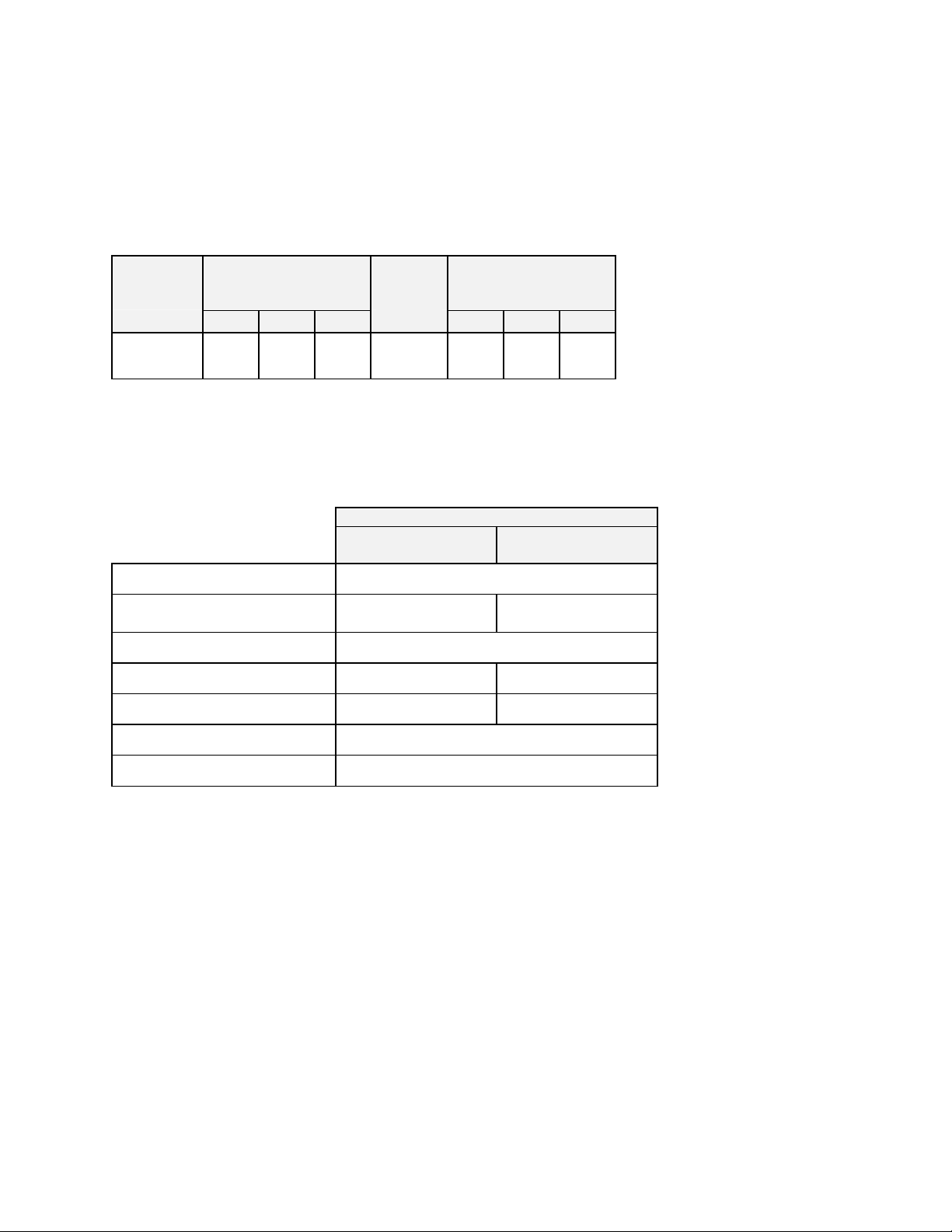
Purge Rate
The chart below shows the time required to reduce the oxygen content to different
percentages of concentration. At a flow rate of 100 SCFH in the RBC1-50 Burn-In
oven, oxygen concentration from 21% in room air down to 6% in the closed oven takes
approximately 11 minutes.
Flow Rate Time Versus Oxygen Content
22
20
18
16
14
12
% O2
10
8
6
4
2
0
0 4 8 12 16 20 24 26
Time in Minutes
31
Page 36
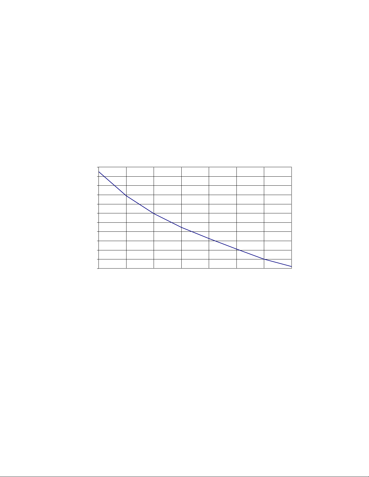
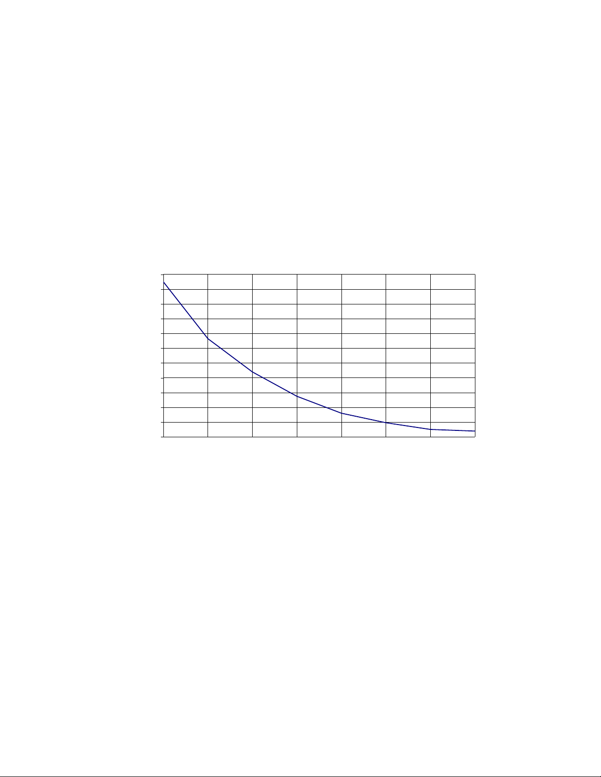
Maintain Rate
The chart below shows typical flow rate required to maintain the oxygen content at
different percentages of concentration in the RBC1-50 Burn-In oven with nitrogen
atmosphere option installed. For example, it requires 36SCFH to keep the oxygen
concentration down to 6½ percent in the closed oven chamber. The preliminary
settings can be determined from this graph. If the oxygen concentration must be
determined more accurately, use an oxygen monitor.
Oxygen Stabilization vs. Flow of N2
22
20
18
16
14
12
%O2
10
8
6
4
2
0
0 9 18 27 36 45 54 63
SCFH-N2
32
Page 37

Troubleshooting
Equipment, which operates for extended lengths
of time, may develop problems. Below are
possible problems and suggested solutions. If
you have a problem not listed and do not know
WARNING
Disconnect the main power switch
or power cord before attempting any
repair or adjustment.
what to do, contact Despatch Industries at our toll free Help Line 800-473-7373.
Difficulty Probable Cause Suggested Remedy
Failure to heat No power
Burned out heater
Control malfunction
Loose wire connections
Heater relay failure
No power to the heater
Airflow switch open
Door switch failure
(if installed)
Slow heat up Improperly loaded
Low line voltage
Heating element(s) are
burned out
Fan motor failure
Frequent heater
element burnout
Erratic temp. or
inaccurate temp.
Excess surface
or door temp.
Harmful fumes generated by
load
Spillage or splattering of
material on heater elements
Overheating oven
Control malfunction
Improper tuning parameters
High limit setting
Improper offset
Door seal deterioration Replace door seal.
Check power source and/or oven and wall fuses.
Replace heater (see warranty.)
Replace control.
Disconnect power and check connections behind
control panel.
Replace circuit board.
Reset High limit(s). Make sure control is calling for
heat. Check controller. Check SSR.
Check airflow switch.
Replace door switch.
Reduce load or redistribute load in chamber.
Supply sufficient power and proper connections.
Check for circuit overload.
Replace heater (see warranty statement.)
Replace fan motor.
Increase vent opening or discontinue process.
Disconnect power and clean oven chamber and
elements.
Check the High limit. Do not operate oven over
260°C (500°F).
Replace control.
Check tuning parameters.
High limit should be 10-25°C higher than setpoint.
Check zone calibration.
:
33
Page 38

Difficulty Probable Cause Suggested Remedy
Improper airflow Fan motor failure
Fan wheel seated too low on
fan shaft
Unbalanced fan wheel
Excessive
vibration
Oven will not
control at
setpoint
Damper motor
(exhaust) not
responding
Liquid nitrogen
(LN2) not cooling
Heater does not
shut down until
temp. reaches
the High limit
setting
Nitrogen (N2) not
flowing correctly
Dirty fan wheel
Unbalanced fan wheel
High limit set too low
Control malfunction
SSR malfunction
Air friction of recirculation fan
Damper motor (exhaust) not
responding
Linkage binding
Motor not working
Improper tuning parameters
Solenoid valve not responding
Improper tuning parameters
Tank empty or valve is to the
OFF position
Pressure regulator set too low
Control malfunction
SSR malfunction
Tank empty or valve is to the
OFF position
Pressure regulator set too low
Flowmeter incorrectly set
Replace fan motor.
Adjust fan wheel for 3/16" clearance between
wheel and inlet ring.
Replace fan wheel.
Clean fan.
Replace fan wheel.
Set the high limit higher
Replace control.
Replace SSR and/or check control output voltage.
Open fresh air vent. Unit will not control below
minimum operating temperature with vent closed.
Check tuning parameters.
Observe and correct linkage.
Check supply and signal voltage.
Check tuning parameters.
Check supply voltage and control output. Replace
valve.
Check tuning parameters.
Check liquid nitrogen (LN2) supply and valve
position.
Adjust regulator to 35PSIG maximum.
Replace control
Replace SSR
Check nitrogen supply and valve position.
Adjust regulator within the acceptable range of the
flowmeter.
Adjust flowmeter to the desired flow rate.
34
Page 39

Circuit Board Check
The circuit board mounted on the control panel has three status LED indicators to help
troubleshoot if the oven is not heating.
• If LED 1 is not lit, check 2F and 3F (control fuses), or power switch.
• If LED 1 and LED 3 are lit but not LED 2, check high limit (and optional door
switch, if installed).
If all three LEDs are lit, check 1F and 4F (heater relay fuses), SSR, heater, heater
fuses, and heater relay.
35
 Loading...