

Page 1

C-197
P/N 157413
REVISION H
11/2007
RBC1-50
WITH PROTOCOL PLUS™
INSTRUCTION MANUAL
RBC1-50 Despatch Ovens are bench ovens designed for operation to 260°C (500°F)
with forced convection airflow.
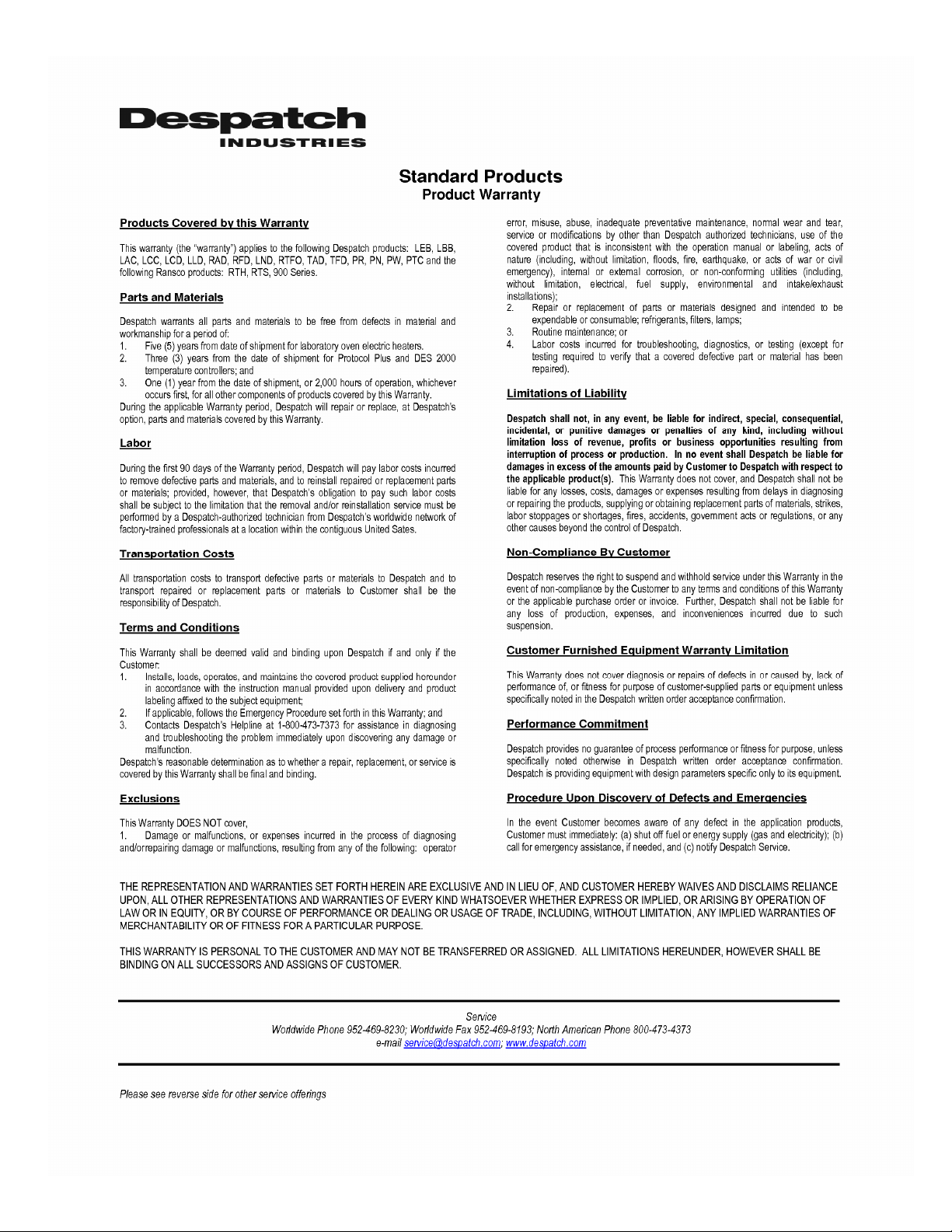
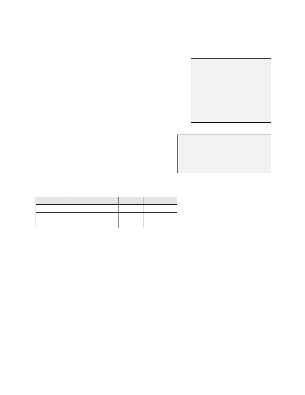
Model Volts Heater watts Amps HZ Phase
RBC1-50 208 3,000 23 60 1
220 3,360 24 50 1
240 4,000 24 60 1
Prepared by:
Despatch Industries
8860 207th St. West
Lakeville, MN 55044
Customer Service 800-473-7373
Page 2

Notice
Users of this equipment must comply with operating procedures and training of operation
personnel as required by the Occupational Safety and Health Act (OSHA) of 1970,
Section 6 and relevant safety standards, as well as other safety rules and regulations of
state and local governments. Refer to the relevant safety standards in OSHA and
National Fire Protection Association (NFPA), section 86 of 1990.
Caution
Setup and maintenance of the equipment should be performed by qualified personnel who
are experienced in handling all facets of this type of system. Improper setup and
operation of this equipment could cause an explosion that may result in equipment
damage, personal injury or possible death.
Dear Customer,
Thank you for choosing Despatch Industries. We appreciate
the opportunity to work with you and to meet your heat
processing needs. We believe that you have selected the
finest equipment available in the heat processing industry.
At Despatch, our service does not end after the purchase
and delivery of our equipment. For this reason we have
created the Service Products Division within Despatch. The
Service Products Division features our Response Center for
customer service. The Response Center will direct and track
your service call to ensure satisfaction.
Whenever you need service or replacement parts, contact
the Response Center at 1-800-473-7373: FAX 612-781-
5353.
Thank you for choosing Despatch.
Sincerely,
Despatch Industries
Page 3
Page 4
i
Page 5

PREFACE
This manual is your guide to the Despatch oven. It is organized to give you the
information you need quickly and easily.
The INTRODUCTION section provides an overview of
the Despatch oven.
The THEORY OF OPERATION section details the
function and operation of assemblies and
subassemblies on the Despatch oven.
The INSTRUCTIONS section provides directions on
unpacking, installing, operating and maintaining the
Despatch oven.
The APPENDIX section contains special instructions
on air atmosphere and nitrogen atmosphere Burn-In
ovens, a Troubleshooting Table, a list of Accessories
and a Warranty.
The parts are listed in the corner of the attached prints, the electrical items on the
electrical print and the mechanical items on the mechanical prints.
An efficient way to learn about the oven would be to read the manual while working with
the corresponding oven control system. This will give you practical hands-on
experience with information in the manual and the oven.
Before operating the equipment, be sure you understand all of the technical information
contained in this manual. Information skipped, not understood or misunderstood could
create the possibility of operating the equipment in an unsafe manner. This can cause
damage to the oven or personnel or reduce the efficiency of the equipment.
NOTE:
Read the entire
INTRODUCTION and THEORY
OF OPERATION before
installing the oven.
WARNING:
Failure to heed warnings in this
instruction manual and on the
oven could result in personal
injury, property damage or
death.
ii
Page 6

Revision B (1-02): Updated drawings
Revision C (4-02): Modified per Rev 3.0 Protocol Plus software
Revision D (5-03): Updated drawings and Despatch Industries Product Warranty
Revision E (2-04): Update drawings
Revision F (3-04): Update drawings
Revision G (8-06): Revised Protocol Plus numbers. Updated Despatch address
Revision H (11-07) Updated warranty
iii
Page 7

TABLE OF CONTENTS
PREFACE........................................................................................................................ i
INTRODUCTION.............................................................................................................1
Special Features.......................................................................................................... 1
Specifications .............................................................................................................. 2
Dimensions .............................................................................................................. 2
Capacities ................................................................................................................2
Temperature ............................................................................................................ 3
Power.......................................................................................................................4
Power Requirements............................................................................................ 4
THEORY OF OPERATION .............................................................................................5
Temperature Control.................................................................................................... 5
Power Switch............................................................................................................... 6
Air Circulation ..............................................................................................................6
Chamber Design.......................................................................................................... 6
Airflow Switch ..............................................................................................................6
Alarm...........................................................................................................................6
Chamber Door Handle................................................................................................. 7
Damper Control ...........................................................................................................7
Determining Damper Settings..................................................................................7
Full Closed Position.............................................................................................. 7
Full Open Position................................................................................................ 8
Minimum Opening for Dissipation of Live Load ....................................................8
Other Damper Settings......................................................................................... 8
OVEN INSTRUCTIONS................................................................................................ 10
Unpacking and Inspection ......................................................................................... 10
Warning Signs Missing.............................................................................................. 11
Set-up........................................................................................................................12
Power Connection ..................................................................................................... 13
Operating...................................................................................................................14
Loading the Oven...................................................................................................14
Oven Temperature Limit ........................................................................................ 14
Product Temperature Limit..................................................................................... 15
Operator Training Requirements............................................................................ 15
Pre-Startup Checklist.............................................................................................16
Startup ...................................................................................................................16
PROTOCOL PLUS CONTROLLER ..............................................................................18
Theory of Control Operation ...................................................................................... 18
Operating Modes....................................................................................................20
Setup Mode............................................................................................................20
Fast Start Mode......................................................................................................20
High Limit...............................................................................................................21
Indicators ...............................................................................................................21
Displays .................................................................................................................22
iv
Page 8

Key Functions ........................................................................................................ 22
Outputs ..................................................................................................................23
Relay (Continued)..................................................................................................24
Communication......................................................................................................24
Optional Software...................................................................................................24
INSTRUCTIONS ........................................................................................................... 25
Start-Up.....................................................................................................................25
Operation...................................................................................................................26
Manual Mode ......................................................................................................... 26
Timer Mode............................................................................................................27
Profile Mode...........................................................................................................28
Auto Start Mode.....................................................................................................28
Setup Mode............................................................................................................29
Instructions for Setup Mode Pages............................................................................ 30
Program Page........................................................................................................30
Profile # ..............................................................................................................32
Sample Profile........................................................................................................33
Auto Start Page (optional)......................................................................................34
PID Page................................................................................................................36
Control Page..........................................................................................................38
Communication Page (optional)............................................................................. 39
Real Time Clock Page (optional)............................................................................ 39
Relay Outputs Page (optional)...............................................................................40
Test Page...............................................................................................................41
Zone Calibration Page ........................................................................................... 42
Sensor Calibration Page ........................................................................................44
Enable Page ..........................................................................................................46
Digital Inputs (optional) .......................................................................................... 47
Error Messages and Alarms ......................................................................................48
Quick Reference and Default Values......................................................................... 49
Technical Specifications ............................................................................................56
Maintenance..............................................................................................................57
Checklist ................................................................................................................57
Inspection and Cleaning.........................................................................................58
Vents..................................................................................................................58
Chamber.............................................................................................................58
Control Cabinet and Fan .................................................................................... 58
Chamber Door Gasket........................................................................................59
Recirculation Motor.............................................................................................59
Oven Exterior......................................................................................................59
Oven Chamber Interior.......................................................................................59
Door Hinges and Latches...................................................................................59
Automatic Damper..............................................................................................60
Controls and Indicators.......................................................................................60
Loose Screws, Bolts and Fasteners ...................................................................60
Lubrication..........................................................................................................60
v
Page 9

Tests......................................................................................................................61
OPTIONAL ACCESSORIES .........................................................................................62
Door Switch ...............................................................................................................62
Recorder....................................................................................................................62
Redundant High-Limit................................................................................................ 62
Disconnect Switch ..................................................................................................... 63
Stacking Option ......................................................................................................... 63
Replacement .............................................................................................................64
Parts.......................................................................................................................64
Nitrogen and Liquid Nitrogen..................................................................................... 64
Theory of Operation...............................................................................................64
Operator Training Requirements............................................................................ 65
Operation...................................................................................................................65
Nitrogen Atmosphere.................................................................................................67
Purge Rate.............................................................................................................67
Maintain Rate.........................................................................................................68
Troubleshooting.........................................................................................................69
Circuit Board Check...............................................................................................71
DRAWINGS .................................................................................................................. 72
APPENDIX: Temperature Scale Conversion and Optional MRC5000 Setup................75
Temperature Scale Conversion (C/F)........................................................................75
Optional MRC5000 Recorder Setup.......................................................................... 76
vi
Page 10

vii
Page 11

INTRODUCTION
This instruction manual covers the operation and
maintenance of the Despatch RBC1-50 Burn-In
oven.
NOTE:
Read the entire
INTRODUCTION and THEORY
OF OPERATION before
installing the oven.
Special Features
The sturdy construction and three-inch insulation top and bottom and four-inches of
insulation on the sides of the Despatch RBC1-50 Burn-In ovens contribute to excellent
temperature uniformity.
Other special features include the following:
• Unique Despatch design to combine higher fan volume of forced recirculated air
with a system of perforated stainless steel walls for the ultimate in temperature
uniformity.
• Welded double wall construction and fiberglass insulation to reduce heat loss.
Silicone rubber gaskets further minimize heat leakage.
• Rapid response heater.
• Scratch-resistant baked enamel exterior and stainless steel interior for easy
cleaning.
1
Page 12
Specifications
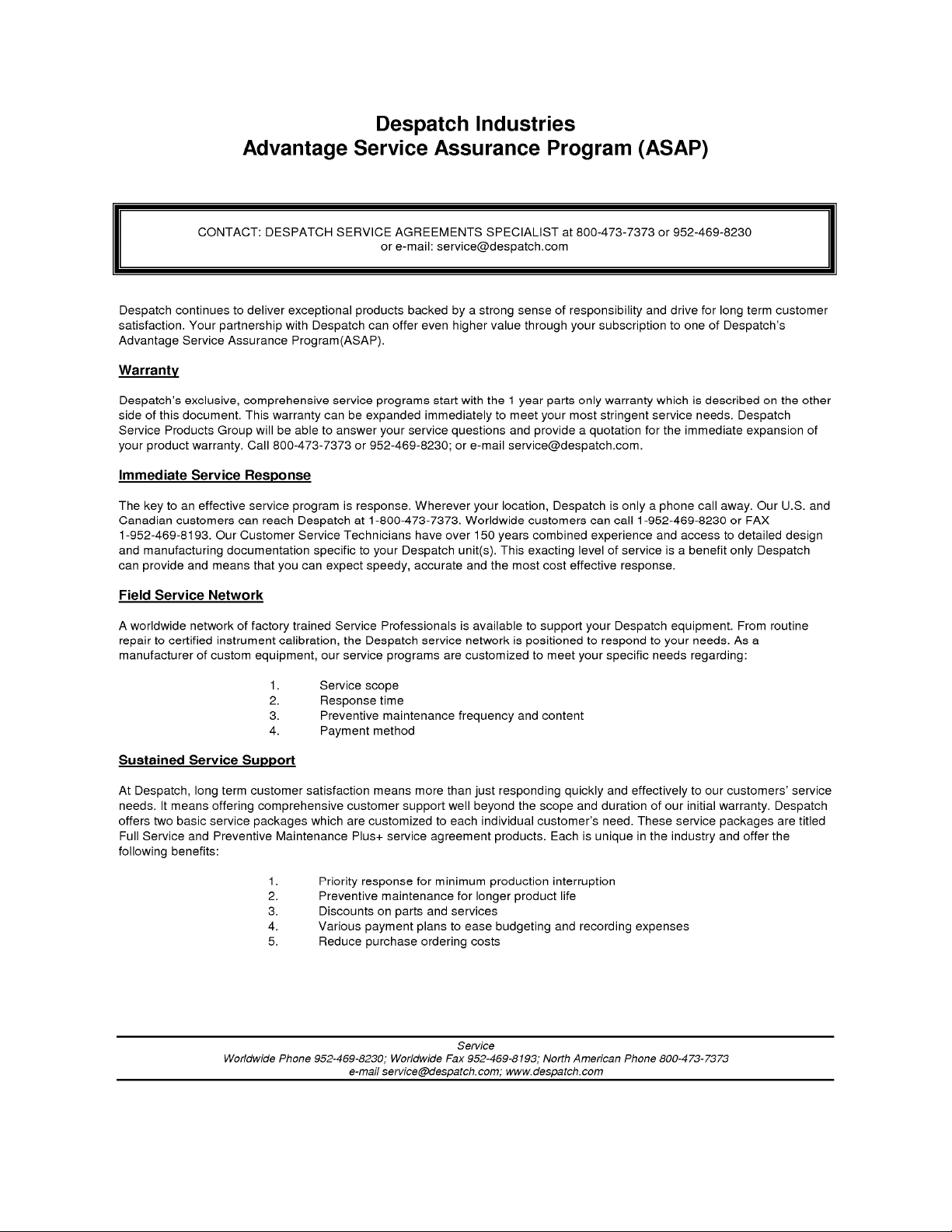
Dimensions
Model Chamber Size
in (cm)
W D H W D H
RBC1-50 18
(46)
25
(64)
(46)
Capacities
Maximum Load 150 Lbs
Fresh Air/ Exhaust Capacity at
125 °C (255 °F)
Recirculating Fan 600 CFM 1 HP
Capacity
feet3
(liters)
18
4.7
(133)
RBC1-50
Air Atmosphere
51 CFM N/A
Overall Size
in (cm)
46
(117)
36
(91)
MODEL
RBC1-50
Nitrogen Atmosphere
31.50
(80)
Fresh Air Inlet 2.5” Diameter N/A
Exhaust outlet 2.18” Diameter N/A
# of Doors 1
Approximate Weight 470 Lbs. (213 KG)
2
Page 13
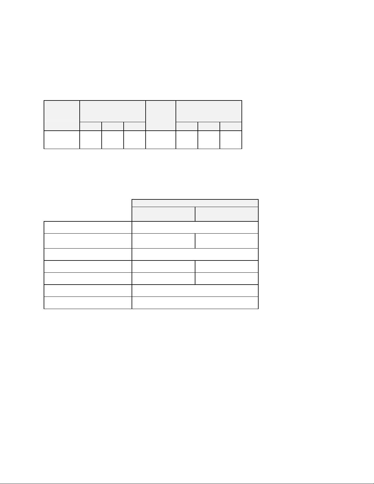
Temperature
RBC1-50
Time to Temperature 25°C - 80°C
(approximate minutes with 25°C - 125°C
no live load)
25°C - 260°C
Recovery Time to 125°C with door open 1 Min.
Temperature Uniformity at
260°C*
Operating Temperature Range
(Based on 25°C ambient, and dampers fully open)
(1)
25°C - 150°C
(2)
125°C*
RBC1-50
Air Atmosphere
4
10
14
34
>1 Min. >1 Min.
<±1°C
±1°C
50° - 260°C 15° - 260°C
Nitrogen Atmosphere
4
10
14
30
<±1°C
±1°C
Control Stability
Repeatability ±0.5°C
Cooldown Time 125° - 60°C
Dissipation/Mean Temperature Rise
125°C
150°C
(1)
Time to temperature will be slightly longer for lower voltages due to heater kW derating (empty oven).
(2)
Figures are based on a nine-point survey in an empty oven. Uniformity can vary slightly depending
on unit and operating conditions.
(3)
∆
In control stability figures represent the change in ambient temperature.
(4)
Dissipation is reduced by 17% on 50-Hertz operation. Temperature gradient/mean temperature rise is
with an evenly distributed live load.
(3)
40 Min. 11 Min.
(4)
80°C
±0.5°C per 5°C ∆
800 Watts/4°C
1,300 Watts/6°C
1,400 Watts/6°C
Note: Testing performed on 240V-1PH-60HZ.
3
Page 14
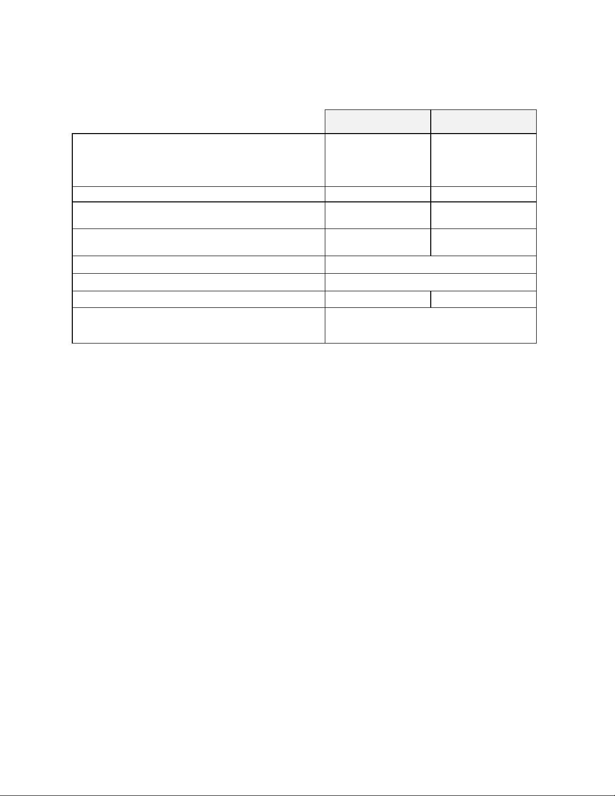
Power
Line voltages may vary in some geographical locations.
If your line voltage is much lower than the oven voltage
rating, warm up time will be longer and motors may
overload or run hot. If your line voltage is higher than
nameplate rating, the motor may run hot and draw
excessive amps.
If the line voltage varies more than 10% from the oven
voltage rating, some electrical components such as
relays, temperature controls, etc. may operate
erratically.
Power Requirements
WARNING:
All grounding and safety
equipment must be in compliance
with applicable codes, ordinances
and accepted safe practices.
WARNING:
Failure to read this warning
can result in death, serious
bodily injury or property
damage. All conductors
must be copper unless the
specific terminal is marked
for use with aluminum
conductors.
Volts Amps Hertz Phase Heater KW
208 23 60 1 3
220 24 50 1 3.4
240 24 60 1 4
4
Page 15

THEORY OF OPERATION
Despatch RBC1-50 Burn-In ovens are made for the accelerated life testing of
microcircuit electronic devices to identify early mortality. The Despatch RBC1-50 ovens
are ideally suited for:
• high-dissipation forward-bias burn-in,
• high temperature reverse-bias burn-in,
• stabilization baking of integrated circuits and other semiconductor devices.
Air atmosphere ovens recirculate air through the chamber. They can add heat and
remove dissipated heat. Air is taken from the burn-in room and circulated through the
oven. Heat is added by electric resistance elements, or removed through automatically
controlled exhaust.
Temperature Control
A Despatch Protocol Plus™ modular microprocessor based digital temperature
controller regulates the process. The Protocol Plus™ operates as a dual functioning
controller/high limit instrument. The control portion utilizes a time-proportioning voltage
signal to control heating, and a milliamp signal to control cooling with minimal
temperature fluctuations.
The controller temperature-sensing element, located in the air return plenum area,
senses the median air temperature of the oven. The controller automatically controls
heat dissipated by sending a signal to the automatic damper modulator. This automatic
damper controls the amount of fresh air drawn into the chamber, preventing excessive
cooling and conserving energy.
The high limit portion protects the product and/or the oven from overheating. If the
product being processed has a critical high temperature limit, the high limit setpoint
should be set to a temperature somewhat below the temperature at which the product
could be damaged. If the product does not have a critical high temperature limit, the
high limit setpoint should be set 5 to 15 degrees higher than the maximum-programmed
setpoint at which the oven will operate. When the high limit trips, the alarm horn will
signal.
Please refer to the Protocol Plus™ instruction section located in this manual for more
detailed information.
5
Page 16

Power Switch
The POWER switch controls power to the control circuit, chamber recirculating fan
motor relay, control cabinet fan, and any options that were included at the time of
purchase.
Air Circulation
A Despatch centrifugal fan draws air through the heater section, moves it evenly across
the chamber, past the temperature sensors and back to the heater. The fresh air is
controlled manually and a modulating damper controls the exhaust.
Chamber Design
The chamber (in which the load is processed) has air supply and exhaust ducts on
opposite sides. The ducts and perforated panels provide uniform airflow and
temperature distribution throughout the chamber.
Airflow Switch
The airflow switch senses the differential pressure between the inlet and outlet side of
the recirculating fan. If there is no air pressure, the switch disconnects power to the
heater, and the alarm horn will signal. An On/Off indicator is visible through a window
on the switch. The switch is located in the upper equipment compartment, behind the
equipment panel and next to the recirculating motor.
Alarm
When there is a high limit condition, or when there is no air pressure sensed by the
airflow switch, an alarm will sound and a red pilot light will be lit. To silence the alarm,
depress the momentary ALARM SILENCE switch. The red light will remain on until the
alarm condition is cleared.
6
Page 17

Chamber Door Handle
The door handle positively engages a cam with a catch in one-quarter turn. The
silicone rubber gasket provides a seal around the door as the handle is moved to the
latched position.
Damper Control
The oven is equipped with a manually adjustable
fresh air damper. The damper blade located on the
rear of the oven. The damper adjustment controls
the flow of fresh air into the chamber. If the damper
is in the full open position, the maximum amount of
fresh air is distributed into the chamber.
The exhaust has a modulating damper motor, which is automatically controlled by the
Protocol Plus™ controller. No adjustments are necessary.
Determining Damper Settings
WARNING: This oven is not
designed for use with flammable
material. If your process
involves flammable material,
contact Despatch Industries.
The optimum setting for the amount of fresh air that should be distributed into the
chamber depends on several factors. These factors include ambient environment
temperature, load conditions, load distribution, heat up rates, cool down rates, desired
temperature uniformity and most importantly the desired operating temperature. To
consider all of these variables at any one point in time is not practical and there are
engineering tradeoffs that should be considered. Therefore guidelines should be used
to determine the fresh air damper setting.
In general, the damper should be set so that the amount of fresh air flowing into the
chamber agrees with the desired operating temperature conditions. The following
outline shows the considerations involved with various damper position settings.
Full Closed Position
When the fresh air damper is in the full closed position, the chamber will be able to
achieve the maximum attainable heat up rates for the chamber. In addition, the
chamber will use the minimum amount of power to operate at the desired temperature.
In almost all cases, the fresh air damper should be in the full closed position in order to
efficiently operate at the maximum operating temperature for the chamber.
7
Page 18

Full Open Position
When the fresh air damper is in the full open position, the chamber will operate at its
minimum operating temperature.
Friction heat from the air recirculation system builds up in the chamber. This causes
chamber temperature to rise slightly even though the heating system is not turned on.
After the recirculation motor has been on for an extended period of time, the chamber
will reach a thermal equilibrium temperature.
When the damper is not set to the full open position, the chamber has no way to readily
dissipate the heat generated by the friction. With the fresh air damper fully open, the
thermal equilibrium temperature is the minimum operating temperature of the chamber.
Minimum Opening for Dissipation of Live Load
To determine the minimum setting for the fresh air damper, only open the damper so
that the fresh air dissipates the heat from live load. To conserve energy, the cooling
output should be trying to control the setpoint temperature with minimal fluctuations.
Close the damper if the heater continues to be cycled on and off. If the cooling is full on
and the chamber temperature is over the setpoint, open the damper.
Other Damper Settings
The damper can be set to several other distinct operating positions. In most cases, the
damper setting is influenced by specific performance factors. Some of these
performance factors are uniformity; cool down rates and required dissipation.
The uniformity of the chamber is influenced by the inside chamber pressure of the
system. The pressure inside the chamber is dependant on the amount of fresh air
flowing into the chamber. When a large volume of fresh air is flowing into the chamber,
the chamber becomes slightly pressurized and the overall temperature uniformity
improves. The slightly pressurized chamber produces the effect of "pushing" the air to
the corners of the chamber. Typically the corners of the chamber will improve with
respect to temperature distribution while the core of the chamber will maintain excellent
uniformity characteristics regardless of the damper position. Therefore, the
pressurization of the chamber typically is a factor when the chamber is loaded heavily.
The best uniformity results, with respect to the product, are achieved when the chamber
is loaded uniformly.
8
Page 19

NOTE: Overpressurizing the chamber can cause hot air to blow out around the door
seal and cause the area around the door to be hot to the touch. To stop this hot air
from entering the room, close the damper slightly until the air stops blowing.
9
Page 20

OVEN INSTRUCTIONS
Failure to heed warnings in this instruction
manual and on the oven could result in death,
personal injury or property damage.
WARNING:
Do not use oven in wet, corrosive or
explosive atmospheres.
Unpacking and Inspection
Remove all packing materials and thoroughly inspect the oven for damage of any kind
that could have occurred during shipment.
• See whether the carton and plastic cover sheet inside carton are still in good
condition.
• Look at all outside surfaces and corners of the oven for scratches and dents.
• Check the oven controls and indicators for normal movement, bent shafts,
cracks, chips or missing parts such as knobs and lenses.
• Check the door and latch for smooth operation.
If there is damage that may have occurred during shipment, follow these instructions.
1. Contact the shipper immediately and file a written damage claim.
2. Contact Despatch Industries to report your findings and to order replacement
parts for those that were damaged or missing.
3. Send a copy of your filed damage claims to Despatch.
4. Next, check to make sure you have received all the required materials. Your
shipment should include:
• One (1) Despatch oven
• One (1) Instruction manual
• Any special options that were ordered at time of purchase
10
Page 21

Warning Signs Missing
If it appears that any warning, danger, caution or information label or sign has been
damaged or lost, contact Despatch Industries for replacements. Call or write:
Service Products Division
Despatch Industries
P.O. Box 1320
Minneapolis, MN 55440
Call Toll Free 800-473-7373
11
Page 22

Set-up
1. Select the location for installing your
oven.
2. Install an exhaust stack from the
exhaust discharge stack to the outside of the building, if required.
• If a round exhaust stack is used, a minimum area greater than the area of
the exhaust stack is required.
• The flashing through the roof or wall must be capable of handling an
exhaust stack temperature up to 260°C (500°F).
• All stacks must comply with state and local building codes to insure that
surrounding combustible surfaces are below 71°C (160°F).
• Design the exhaust stack to limit the amount of restrictions to insure
proper airflow. If more than two (2) elbows are used in the stack, over all
airflow will be reduced.
a. The exhaust could be vented into a burn-in room atmosphere or
other exhaust system capable of handling the total rated heat
dissipation in:
BTUH
×
b. We recommend that the ovens be vented to the outside or to an
area that could use the heat. The maximum exhaust temperature
could reach the maximum operating temperature of the oven.
3. Place oven on a bench top or directly on the floor. The oven must have a
minimum 2-inch clearance in the rear to provide proper ventilation. When placed
next to another cabinet, or next to another oven, a 3-inch clearance is required.
The doors will still open.
4. Make sure oven is level and plumb; this will assure proper heat distribution and
operation of all mechanical components.
5. The atmosphere where the oven is used should be clean, free of solvent vapors.
Good results depend on a clean workspace.
3,412 KW ×
KW
WARNING:
Do not use the oven in wet, corrosive or
explosive atmospheres.
BTUH
+
2,500
KW
HP Fan ionRecirculat
12
Page 23

Power Connection
Be sure the oven is connected to the power source
shown on the nameplate. Connect the oven directly
to your electric supply, with all grounding and safety
equipment, according to applicable codes, ordinances
and accepted safe practices.
Line voltages may vary in some geographical
locations. If your line voltage is much lower than the
oven voltage rating, the warm up time will be longer
and the motors may overload or run hot. If the line
voltage varies more than ±10% from the oven voltage
rating, the temperature control may operate
erratically.
WARNING
Failure to read this warning
can result in death, serious
bodily injury or property
damage. All conductors must
be copper unless the specific
terminal is marked for use with
aluminum conductors.
WARNING
All grounding and safety
equipment must be in
compliance with applicable
codes, ordinances and
accepted safe practices.
:
:
13
Page 24

Operating
Users and operators of this oven must comply
with operating procedures and training of
operating personnel as required by the
Occupational Safety and Health Act (OSHA)
of 1970, Section 5 and relevant safety standards, and other safety rules and regulations
of state and local governments. Refer to the relevant safety standards in OSHA and
National Fire Protection Association (NFPA), Section 86 of 1990.
Loading the Oven
Despatch Industries cannot be responsible for either the process or process
temperature used, or for the quality of the product being processed. It is the
responsibility of the purchaser and operator to see that the product undergoing
processing in a Despatch oven is adequately protected from damage.
Carefully following the instructions in this manual will help the purchaser and operator in
fulfilling that responsibility.
Distribute the workload evenly so that airflow
is not restricted. Do not overfill your oven.
The workload should not take up more than
two-thirds of the cross-sectional air-delivery
area.
WARNING
Do not use oven in wet, corrosive or
explosive atmospheres.
WARNING
Do not heat any closed containers,
flammable solvents or other flammable
material in this oven. (Examples: spray
can, sealed jar of water, alcohol,
kerosene, oil, paper, etc.)
:
:
Oven Temperature Limit
Do not attempt to exceed the maximum or minimum operating temperature of this oven.
14
Page 25

Product Temperature Limit
If the product has a critical high temperature
limit, the HIGH-LIMIT control should be used
as a process HIGH-LIMIT. When used as a
process HIGH-LIMIT, the control should be
set to a temperature somewhat below the
temperature at which the product would be
damaged. A pyrometer could be used to
determine the process HIGH-LIMIT setting. If
the destructive temperature of the product is
already known, this could be used as a point
below which the process HIGH-LIMIT could
be set.
NOTE
Despatch Industries cannot be
responsible for either the process or
process temperature used, or for the
quality of the product being
processed. It is the responsibility of
the purchaser and operator to see that
the product undergoing processing in
a Despatch Industries burn-In oven is
adequately protected from damage.
Carefully following the instructions in
this manual will assist the purchaser
and operator in fulfilling that
responsibility.
:
Operator Training Requirements
All users must be thoroughly trained under the supervision of experienced personnel.
The operator must be aware of the possible dangers of:
• Suffocation from nitrogen,
• Frostbite from nitrogen as a liquid or as a frozen gas,
• Fire.
Users must demonstrate an understanding of the equipment and its operation to assure
knowledge of and practice of safe and proper operating procedures. Users should
receive regular retraining and testing as required to maintain a high level of proficiency
and effectiveness.
Training should include the:
• function of controls and safety devices,
• handling of special atmospheres (on units with LN2 or GN2).
15
Page 26

Pre-Startup Checklist
• Know the system. Read this manual carefully. Make use of its instructions and
explanations. Safe, continuous, satisfactory, trouble-free operation depends
primarily on the degree of your understanding of the system and your willingness to
keep all parts in proper operating condition.
• Check line voltage. Voltage must correspond to nameplate requirements of motors
and controls. Refer to the section on power connections in the INTRODUCTION of
this manual.
• Fresh air and exhaust. Do not be careless about restrictions in and around the fresh
air and exhaust openings and stacks. Under no condition permit them to become so
filled with dirt that they appreciably reduce the air quantity. The proper ventilation
clearances should be fulfilled at all times. Refer to the Set-up instructions in this
manual.
Startup
For fastest oven heat-up time, close the fresh-air vent. After the desired temperature is
reached, the vent may be adjusted as needed.
1. Start Fan.
• Open oven door.
• Press Power switch to the ON
position. You will hear the
recirculating fan start.
• Shut oven door.
• Check that the control display turns on.
2. Operate the temperature control as desired by following the Protocol Plus™
instruction section located in this manual for more detailed information.
3. When the oven nears temperature set on the
control, the heater will start cycling on and
off.
4. When the chamber temperature is above
setpoint on control, the cooling output of the control will start driving the damper
open, which will exhaust air from the chamber.
WARNING
Do not heat any closed containers,
flammable solvents or other flammable
material in this oven. (Examples: spray
can, sealed jar of water, alcohol,
kerosene, oil, paper, etc.)
:
WARNING
Hot surfaces may exist around
door, inside cabinet, product, and
fixtures. Handle with care.
:
16
Page 27

5. If temperature of the chamber exceeds the high-limit setting on the control, the
heater will shut down and the Alarm Horn and red pilot light will energize. The
heater will shut off. To silence the alarm:
• Depress the Alarm Silence switch, this is a momentary switch, it will return
to its normal position when released.
• The alarm horn will be silenced, but the red alarm pilot light will remain lit.
• When the overtemperature condition clears, press RESET on the control.
• The heater should be back on and the control should be functioning
correctly.
• If the high-limit trips repeatedly, verify the cause of overtemperature and
correct problem.
6. If the fan stops running during process, the Airflow switch will trip and the Alarm
Horn and pilot light will energize. The heater will shut off.
• Shut down the chamber and correct the problem.
7. Shut down chamber by lowering the
setpoint on the control, usually to ambient,
20°C (70°F).
8. Turn the power switch to OFF.
WARNING
On all manual and on all auto
processes, the fans should remain
in operation until oven temperature
is below 150°C (300°F).
:
17
Page 28

PROTOCOL PLUS CONTROLLER
The special features of the Protocol PlusTM control include:
• PID tuning
• Ramp/Soak programming of up to 64 segments
• Segment looping and profile linking
• Built-in manual reset high limit control
• Built-in process timer
• Dedicated LED display for process temperature
• Multi-purpose two-line LCD display with backlight
• Auto-tuning
• Security access
• Process temperature retransmission signal
• Digital inputs for remote profile control
• Optional relay outputs for events, alarms, or end-of-cycle signal
• Optional real-time-clock
•
Optional RS232/RS422/RS485 MODBUS communications
Theory of Control Operation
The Protocol Plus is a modular microprocessor based digital temperature controller. The
Protocol Plus operates as a dual functioning controller/high limit instrument. The control
portion utilizes a time-proportioning voltage signal to control heating devices with
minimal temperature fluctuations.
The high limit portion protects the product and/or the oven from overheating. If the
product being processed has a critical high temperature limit, the high limit setpoint
should be set to a temperature somewhat below the temperature at which the product
could be damaged. If the product does not have a critical high temperature limit, the
high limit setpoint should be set 5 to 15 degrees higher than the maximum programmed
setpoint at which the oven will operate.
18
Page 29

Protocol Plus Faceplate and Wiring Diagram
19
Page 30

Operating Modes
The Protocol Plus control has five modes of operation available:
Stopped Mode:
Manual Mode:
Timer Mode:
Profile Mode:
Auto Start Mode (optional):
The optional event outputs can be utilized during Manual, Timer, or Profile modes.
All control and relay outputs are off. Stopped Mode is integrated
into each of the following four modes of operation.
Control operates as a single setpoint control until Stopped mode is
accessed
Control operates as a single setpoint control until preset time period
has expired.
Control operates as a ramp/soak profiling control until the end of
the profile. 8 profiles are available with up to 8 ramp/soak segments
in each profile.
Control may automatically start Manual, Timer, or
Profile mode based on a preset time and day.
Requires the optional real-time clock feature.
Setup Mode
The control has a Setup Mode which provides access to control configuration and
programming of profiles. The Setup Mode contains ten separate electronic Pages where
the configuration and programming parameters (Menu items) are found. The Setup
Mode Pages are described in detail elsewhere in this manual.
Fast Start Mode
The Protocol Plus control has the ability to automatically start an operating mode when
power is applied. This feature may be useful if the same mode of operation is used
everyday. The user can turn on the power and the oven will start the desired process
automatically. The Fast Start Mode is controlled by the Power-Up Start parameters on
the Control page (see Setup Mode).
20
Page 31

High Limit
The control has an integrated high limit function which will disable the heater output
when tripped. If the high limit does trip, the relay will need to be manually reset. When
the high limit relay is tripped, the Hi-Limit indicator will be lit. Allow the oven to cool
several degrees (or increase the high limit setpoint) and then press the Reset key. The
indicator will turn off.
The control will not allow the high limit setpoint to be set below the current setpoint
value.
Indicators
The Protocol Plus control has 12 indicating LEDs that provide operational information to
the user.
Χ
Power LED:
Χ
Heater LED:
Χ
Profile LED:
Χ
Timer LED:
Χ
Manual LED:
Χ
Cycle Complete LED:
Χ
Hi-Limit Alarm LED:
Χ
Soak Alarm LED:
condition.
Χ
Outputs 1 through 4:
These outputs may be configured as timed event outputs, process temperature trip
point outputs, alarm outputs, or as an end of cycle relay output. The ON state can
be configured as energized or de-energized.
Indicates that power is supplied to the instrument.
Indicates that the heater output is active.
Indicates that the Profile Mode is in operation.
Indicates that the Timer Mode is in operation.
Indicates that the Manual Mode is in operation.
Indicates that the control is in Stopped mode.
Indicates that the high limit relay has tripped (de-energized).
Indicates that the guaranteed soak deviation is in alarm
Indicate that the optional relay outputs are in the ON state.
21
Page 32

Displays
The Protocol Plus control has two displays. A dedicated LED upper display shows the
oven temperature. A two-line LCD lower display provides information on control status
and allows changes to be made to the control settings.
Key Functions
The Protocol Plus control has seven keys that provide operation.
•
•
•
•
•
•
Select key:
number or relay. In Profile/Run Mode, press simultaneously with the UP key to
advance a segment.
Run/Hold key:
Mode is running, pressing the Run/Hold key will place the Profile (or Timer) in
Hold status. A subsequent press will resume the Profile (Timer).
Stop key:
Page/Reset key:
configuration, Press this key to silence an alarm if the instrument alarm sounds
during operation. In an operating mode, if an alarm or error condition occurs,
press this key to return the instrument to normal operation once the condition is
cleared.
Menu/View key:
display the high limit setpoint. While in Setup Mode, pressing this key will provide
access to each Menu parameter.
keys:
Mode, press to select profile to run. In Profile/Run Mode, press key
simultaneously with the Select key to force the program to advance one
segment.
Press to select mode of operation. In Setup Mode, to select profile
Press to activate a mode of operation. If a Profile (or Timer)
Press to stop any mode of operation.
While in Setup Mode, press to access different Pages of
While running any operating mode, pressing this key will
Press these keys to adjust parameter settings. In Profile/Stopped
22
Page 33

Outputs
The Protocol Plus control has seven different outputs available.
•
Heating output:
is time-proportioned and designed to control a heat control device such as a solid
state relay.
•
High limit:
normal operating conditions. If the control senses a temperature higher than the
high limit setpoint, or if there is a sensor error, the high limit relay will de-energize
until the condition is cleared and the Reset key is pressed. When the high limit
relay is de-energized, the heater is disabled.
•
Retransmission:
(DC) signal that is proportional to the process temperature. The signal can be an
input to other devices such as a chart recorder.
•
Relay (four optional outputs):
configured to function as alarms, events, or end of cycle. These outputs can be
utilized in Manual, Timer, or Profile Mode.
The high limit output is a form C relay which is energized under
The control output is a DC voltage open-collector output which
The retransmission output is a DC 0 to 5 volt or 4 to 20 ma
The four form A dry contact relay outputs can be
Layout for Optional Components
23
Page 34

Relay
Use the Relay Card Optional Ay p/n 144562 to add relays to the standard controller.
Each relay card contains two relays (maximum of two cards Ay’s allowed).
(Continued)
Communication
The Protocol Plus control has optional MODBUS communication available which can
communicate via RS232, RS422, or RS485 to a computer. See communications option
assembly p/n 141877 for board and cable assembly. Please refer to the MODBUS
communications manual which comes with this option.
Optional Software
The Protocol Manager program allows the operator to start/stop multiple ovens (32
maximum) from a personal computer. A data log can also be used to record process
information (p.n. 140008).
24
Page 35

INSTRUCTIONS
Start-Up
These instructions are provided as a quick reference for operating the Protocol Plus
control. If the Profile Mode is to be used, or the configuration of the control needs to be
changed, please refer to the Setup Mode instructions before operating the control. For
more detailed operating instructions refer to the Operation instructions for the mode you
wish to use.
Upon initial power-up the control is in Manual/Stopped Mode (unless the Autostart or
Fast Start Modes are active). To activate any operating mode from Stopped Mode,
press the Select key until the desired mode is displayed, then press the Run key. If the
proper Profile number is not displayed when the Profile Mode is accessed, press the
or keys until the desired Profile number is displayed, then press the Run key. If no
profile numbers can be displayed (display only reads NONE) then no profiles are
currently programmed (see Setup Mode).
The temperature setpoint can be adjusted while Manual or Timer Mode is running by
pressing the UP or DOWN key.
To momentarily hold the Timer or Profile Mode, press the Hold key. To continue the
Timer or Profile Mode, press the Run key.
To return to Stopped Mode at any time, press the Stop key and the cycle complete LED
will illuminate.
Note that the control can be configured to automatically activate Manual, Timer or
Profile Mode when power is applied (power switch turned on). See Control Page in the
Setup Mode to utilize the Fast Start mode.
25
Page 36

Operation
Manual Mode
Press the Select key until Manual is displayed (note you can press the Run key at any
time to activate Manual Mode).
1. Press the Menu key to display the Process Temperature Setpoint (setpt). You
can change the Setpoint with the keys.
Note:
set to DISABLED, it must be changed to ENABLED before any changes to the
process temperature and high limit setpoints can be made.
2. Press the Menu key a second time to display current high limit setpoint (Hi-Lim
SP). The value can be adjusted by pressing the keys. If
the high limit band feature is activated (see Control page) and the high limit can
not be adjusted.
3. (optional feature) Press the Menu key a third time to display Event1. Press the
key to turn on the event or to turn off the event. Repeat for all events which
are enabled (up to 4).
4. To start Manual Mode, press the Run key.
The display will change from Stop to Run. To return to Stopped Mode, press the
Stop key. While in operation, the process setpoint can be adjusted by using the
will display the High Limit Setpoint (HLSP) setting.
If changes to the high limit setpoint or event output configuration are needed, they must
be done from the stopped mode.
If the SPChange parameter on the Enable page in Setup Mode has been
Band
keys to change the value while the mode is running. Pressing the Menu key
is displayed,
26
Page 37

Timer Mode
1. Press the Select key until Timer is displayed (note you can press the Run key at
any time to activate Timer Mode).
2. Press the Menu key to display the Process Temperature Setpoint (Setpt). You
can change the Setpoint with the keys.
Note
that if the SPChange parameter on the Enable page in Setup Mode has
been set to DISABLED, it must be changed to ENABLED before any changes to
the process temperature and high limit setpoints can be made.
3. Press the Menu key a second time to display current high limit setpoint (Hi-lim
SP). The value can be adjusted by pressing the keys. If
the high limit band feature is activated (see Control page) and the high limit can
not be adjusted.
4. Press the Menu key a third time to display Time Set. You can change the time
setting with the keys.
5. (optional feature) Press the Menu key a fourth time to display Event1. Press the
key to turn on the event or to turn off the event. Repeat for all events which
are enabled (up to 4).
6. Press the Menu key a fifth time to display the current guaranteed soak band
(TmrGuarSoak) value. If the process temperature deviates from the setpoint by
more than this value, the timer is placed in a hold condition. The timer continues
when the process temperature falls within range. Reference the Quick
Reference and Default Values section for available settings.
7. To start Timer Mode, press the Run key.
The display will change from Stop to Run and the time remaining will be
displayed. To return to Stopped Mode, press the Stop key. While in operation,
the process setpoint can be adjusted by using the keys to change the value
while the mode is running. Pressing the Menu key will display the High Limit
Setpoint.
Pressing the Run/Hold key while the Timer Mode is in operation will put the control in
Hold status. The Timer LED will flash to indicate the held status. Press the Run/Hold
key again to continue timing. The Timer LED will return to lit status.
Band
is displayed,
27
Page 38

Profile Mode
1. Press the Select key until Profile is displayed. “None” may be displayed if a
profile has not been selected or no profiles entered.
2. Press the key to display the desired profile to run.
3. To start Profile Mode, press the Run key.
The display will change from Stop to Run and the segment time remaining,
Temperature Setpoint, Profile #, along with the current segment number, will be
displayed. To return to Stopped Mode, press the Stop key.
Pressing the Run/Hold key while the Profile Mode is in operation will put the control in
Hold status. Press the Run/Hold key again to continue the mode. The Profile LED will
flash to indicate the hold status.
To advance to the next segment while running a profile, press the Select and UP arrow
keys at the same time.
Note that ramping down too fast may cause the high limit relay to trip unexpectedly if
the high limit band feature is used. This can be avoided by using a separate cooling
profile that does not utilized the high limit band and then jumping to that profile to
perform rapid cooling.
Auto Start Mode
The Auto Start Mode allows the control to start Manual, Timer, or Profile mode
automatically at a preset time and day. See the Auto Start Page in Setup Mode for the
time, day, and operating mode settings. The Auto Start Mode requires the optional Real
Time Clock feature for operation.
To activate the Auto Start Mode, the control must first be in Stopped Mode.
1. Press the Select key until Auto Start is displayed.
2. Press the Menu key.
3. Press the keys to activate or deactivate the Auto Start feature.
Note that once you activate Auto Start, you can continue to use all operating modes as
normal. If an operating mode is running at the time of a preset Auto Start function, and
Auto Start is activated, the existing operating mode will override the auto Start function
and the Auto Start will not turn on. To use the Auto Start for the next day, the auto start
must show in the LCD display that it is active.
28
Page 39

Setup Mode
Configuration of the control and programming of the ramp/soak profiles must be done in
the Setup Mode. To access Setup Mode, the control must first be in Stopped Mode.
1. Press the Select key until Setup is displayed.
2. Press the Page key and Security will be displayed.
3. Press the Menu key and Password will also be displayed. Use the keys to
enter the proper password.
4. Once the proper password is displayed, press the Page key twice to enter the
Setup Mode.
To exit Setup Mode, press and hold the Page key for three seconds.
The control has two levels of password-protected security. Level one provides access
only to those menu pages that are enabled on the Enable page. Level two provides
access to all menu pages, including the Enable page. The default security password
values are 1 for level one and 2 for level two.
If an improper password has been entered, the control will remain at the Security
display. To enter the proper password, press the Menu key. To exit Setup Mode, press
and hold the Page key for three seconds.
Mapping of the Setup Mode is provided in the following sections. To access each
parameter Page, which are described in detail in the following sections, press the Page
key until the desired page heading is displayed. Press the Menu key to access each
Menu parameter. Press the keys to change Menu parameter settings.
Refer to the Quick Reference and Default Values section for available settings for each
Menu parameter.
Press the Page key to continue with each Page, or press and hold the Page key for
three seconds to exit Setup Mode.
29
Page 40

Instructions for Setup Mode Pages
Program Page
Programming of the profiles is provided on the Program Page. Eight profiles are
available with up to eight ramp and soak segments per profile.
If the optional relay outputs are installed, they must be configured as alarms or events
on the Relay Outputs Page before they can be utilized. If configured as event outputs,
these relays can be used as time or temperature events.
When entering the Program Page, press the Select key to select the profile you wish to
enter/edit, then press the Menu key. The first parameter (Profile #, Segment 1, Ramp
Time) will display. Adjust the time value with the keys. Once the proper value is
displayed, press the Menu key to continue. Continue with the Menu key to adjust/view
each parameter.
If the ramp time value of the current segment is left at 0:00, the next press of the Menu
key will advance the control to the High Limit Setpoint parameter for that profile.
Continue entering / verifying all parameters until you get to the last parameter
(Guaranteed Soak Band). Once all parameters have been properly entered, press the
Page key to return to the top of the Profile Page. You can press the Select key to
enter/edit another profile, press the Page key to access another page, or press and hold
the Page key to exit Setup mode.
While editing any profile, pressing the Select key will advance the control to the time
value for the next segment, until the last segment has been reached. This allows faster
editing of the profile rather than pressing the Menu key to advance past each
parameter.
To run a profile indefinitely, link the profile to itself.
30
Page 41

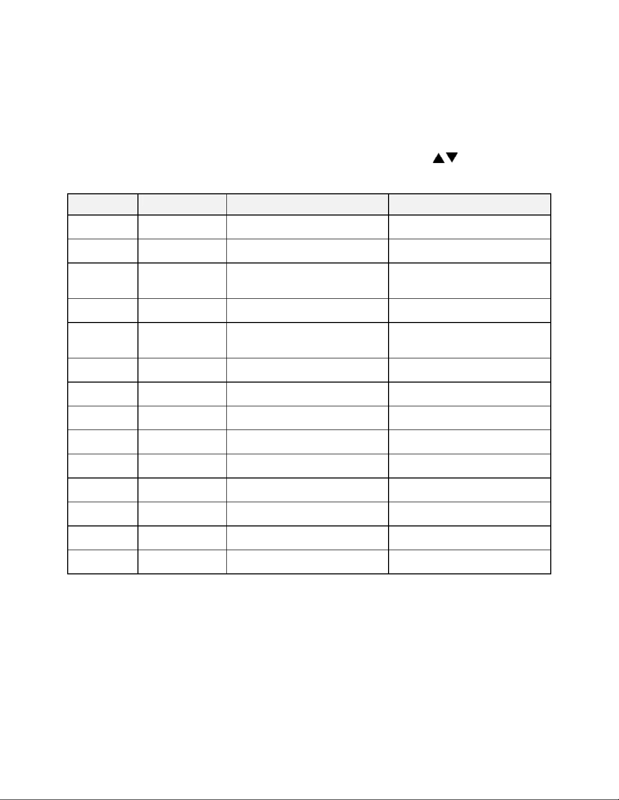
Menu Item Display Description
Ramp Time Seg 1 Pro-1 Seg-1 Ramp Time Ramp time for segment 1 of profile
Event 1 Set Value* Pro-1 Seg-1 Ramp Event 1 Event 1 setting for segment 1 ramp of profile
Event 2 Set Value* Pro-1 Seg-1 Ramp Event 2 Event 2 setting for segment 1 ramp of profile
Event 3 Set Value* Pro-1 Seg-1 Ramp Event 3 Event 3 setting for segment 1 ramp of profile
Event 4 Set Value* Pro-1 Seg-1 Ramp Event 4 Event 4 setting for segment 1 ramp of profile
Soak Temp Seg 1 Pro-1 Seg 1 Soak Temp Soak temperature for segment 1 of profile
Soak Time Seg 1 Pro-1 Seg 1 Soak Time Soak time for segment 1 of profile
Event 1 Set Value* Pro-1 Seg-1 Soak Event 1 Event 1 setting for segment 1 soak of profile
Event 2 Set Value* Pro-1 Seg-1 Soak Event 2 Event 2 setting for segment 1 soak of profile
Event 3 Set Value* Pro-1 Seg-1 Soak Event 3 Event 3 setting for segment 1 soak of profile
Event 4 Set Value* Pro-1 Seg-1 Soak Event 4 Event 4 setting for segment 1 soak of profile
(repeat for segments 2-8, until ramp or soak time = 00:00)
High Limit Setpoint Pro-1 Hi-Lim SP High limit setpoint for profile**
Loop From Pro-1 Loop From Seq To start a loop action in a profile
Loop To Pro-1 Loop To Seq To end a loop action in a profile
Loop Count Pro-1 Loop Number Number of times to execute loop
Profile Link Pro-1 Link To Pro To jump from this profile to another
Guaranteed Soak Pro-1 Guar Band Guaranteed soak band for profile
See the definitions on the following pages for parameter ranges.
* only available if optional relay outputs are installed (repeat all for profiles 2-8)
** Set to
Band
to use the high limit band feature
31
Page 42

Profile #
There are eight profiles available.
Segment#
Ramp Time
EV1 through 4
Soak Temp.
Soak Time
EV1 through 4
Recipe segments 1 through 8 may be programmed, each with its own
set of events, ramp and soak times, and soak temperature.
The time required to ramp from one setpoint up to another setpoint.
Values between 0 and 99:59 are allowable. In the Protocol Plus
controller, the profile ramp and soak times are stored without units.
Units are set as either hours and minutes (HH:MM) or minutes and
seconds (MM:SS). The setpoint will automatically increment from the
actual temperature to the soak temperature.
From 1 to 4 events may be programmed into the ramp time portion of
each segment here. These typically involve actuating/disabling relays
to close/open valves or perform other relay-controlled functions.
NOTE: These will only actuate when the controller has the relay cards
installed and programmed for an event.
The temperature setpoint of a particular segment is entered here; it
can range from -18 to 540 degrees C (0 to 1000 degrees F).
The duration of soak is entered here; the value can range from 0 to
99:59.
From 1 to 4 events may be programmed into the soak portion of each
segment here. These typically involve actuating/disabling relays to
close/open valves or perform other relay-controlled functions. NOTE:
These will only actuate when the controller has the relay cards
installed and programmed for an event.
Hi Limit SP
Loop From
Loop To
Loop Number
Profile Link
Guaranteed
Soak Band
The high limit setpoint may be entered here; if the temperature
exceeds this value, the hi-limit will alarm and shut off the heater.
Values are No, Seq-1 to Seq-8.
Values are No, Seq-1 to Seq-8.
Values are 0 - 99.
These values enable the operator to jump from a certain step to
another step of the recipe a preset number of times.
Values are STOP/HOLD/1 - 8. When the profile ends, the profile can
turn the heater off, hold the temperature setpoint at the end of the
profile, or jump to another specified profile.
If the process temperature deviates from the setpoint by more than
this value, the soak timer is placed in a hold condition. The timer
continues when the process temperature falls within range.
32
Page 43

Sample Profile
Programming Table
Profile Number
Segment
Time
1 01h00 100 01h00
2 02h00 50 00h01
3 00h00
4
5
6
7
8
High Limit Setpoint 115
Loop From Seq No
Loop To Seq No
Loop Number 0
Link To Pro No
Guar Soak Band 10
____1______
Ramp
Events
1
2
Profile Name
3
4
Temp-
erature
__________
Time
Soak
1
Events
2
3
4
33
Page 44

Auto Start Page (optional)
If the optional real time clock has been installed, the Auto Start Page can be configured
to automatically start Manual, Timer or Profile Mode at a specified time and day. Note
that if Auto Start Enable is set to Yes in the Setup Mode, the Auto Start feature is not
turned on - it is available to the operator to be activated in Stopped Mode.
To configure the Auto Start feature:
1. Access the Setup Mode.
2. Press the Page key until Auto Start is displayed.
3. Press the Menu key. If there is no change in the display, the controller may not
have the realtime clock option.
4. Set Auto Start Enable to Yes.
5. Using the Menu key, scroll through the options available and use the keys
to set the mode desired for each day of the week. You may select from Manual,
Timer, or Profile 1 through 8.
6. When the mode is set press the Menu key.
7. Enter the time of day you wish the mode to activate.
8. Continue through the rest of the week by pressing the Menu key, or press the
Page key when done.
One Auto Start mode can be set for each day of the week. Exit the Setup mode by
pressing and holding the Page key for three seconds. Press the Select key until Auto
Start is displayed. Make sure the correct time and day is displayed. If not proper, set it
to the correct time on the Real Time Clock Page in the Setup mode. Press the Run key
to activate Auto Start. The display will change from Stop to Active. When the preset time
and day occurs, the appropriate operating mode will start. You can de-activate Auto
Start by pressing the Select key until Auto Start is displayed, then pressing the Stop
key.
Note that once you activate Auto Start, you can continue to use all operating modes as
normal. If an operating mode is running at the time of a preset Auto Start function, and
Auto Start is activated, the existing operating mode will override the Auto Start function
and the Auto Start will not turn on.
34
Page 45

Menu Item Display Description Range
Enable
Autostart
Sunday
mode
Sunday
time
Monday
mode
Monday
time
Tuesday
mode
Tuesday
time
Wednesday
mode
Wednesday
time
Thursday
mode
Thursday
time
Friday
mode
Friday time Auto Start Fri
Saturday
mode
Saturday
time
Auto Start Enable Enable (yes) or disable (no) the
Auto Start Sun
Mode
Auto Start Sun
Time
Auto Start Mon
Mode
Auto Start Mon
Time
Auto Start Tue
Mode
Auto Start Tue
Time
Auto Start Wed
Mode
Auto Start Wed
Time
Auto Start Thu
Mode
Auto Start Thu
Time
Auto Start Fri
Mode
Time
Auto Start Sat
Mode
Auto Start Sat
Time
No, Yes
Autostart function
Set mode on Sunday to activate Off, Manual, Timer, Pro-1 to Pro-8
Set time on Sunday for mode to
activate
Set mode on Monday to activate Off, Manual, Timer, Pro-1 to Pro-8
Set time on Monday for mode to
activate
Set mode on Tuesday to activate Off, Manual, Timer, Pro-1 to Pro-8
Set time on Tuesday for mode to
activate
Set mode on Wednesday to
activate
Set time on Wednesday for mode
to activate
Set mode on Thursday to activate Off, Manual, Timer, Pro-1 to Pro-8
Set time on Thursday for mode to
activate
Set mode on Friday to activate Off, Manual, Timer, Pro-1 to Pro-8
Set time on Friday for mode to
activate
Set mode on Saturday to activate Off, Manual, Timer, Pro-1 to Pro-8
Set time on Saturday for mode to
activate
00:00 to 23:59
00:00 to 23:59
00:00 to 23:59
Off, Manual, Timer, Pro-1 to Pro-8
00:00 to 23:59
00:00 to 23:59
00:00 to 23:59
00:00 to 23:59
35
Page 46

PID Page
The PID Page contains parameters which control the response to the setpoint and
process variable input. To access the PID Page, enter the Setup Mode (see description
earlier in this manual). Press the Page key until PID is displayed. Press the Menu key.
Each parameter can be changed by pressing the Menu key until the desired parameter
is displayed, and then pressing the keys to change the value.
Menu Item Display Description Range
Display units PID Temp Unit Set display units to °C or °F °C or °F
Proportional
band
Integral reset PID
Derivative
Rate
AutoTune PID AutoTune Enable auto tuning function Disable, Enable
PID Prop Band Set proportional band for tuning 1 to 56°C (1 to 100°F)
Set integral reset for tuning 0 to 100 seconds/repeat
Reset/Rep/Min
PID Rate In Sec Set derivative rate for tuning 0 to 500 seconds
The AutoTune parameter disables or enables the AutoTune function. To utilize
AutoTuning:
36
Page 47

1. Access the Setup Mode.
2. Press the Page key until the display reads AutoTune. Press the key to enable
the AutoTune.
3. Press the Page key for three seconds to exit Setup Mode.
4. Cycle power to the instrument.
5. Set Manual Mode to run. The display will alternately display AutoTune and
Manual.
If the Manual Mode setpoint is less than 50 degrees higher than the actual process
temperature, the AutoTune function will create an error condition. This can be cleared
by either cooling off the process temperature or increasing the setpoint until there is
more than 50 degrees between them. Once the AutoTune function is allowed to
complete tuning, the AutoTune parameter will disable by itself.
If you wish to cancel the AutoTune function, press the STOP key, access the PID page
in Setup Mode, and set the AutoTune parameter to Disable.
37
Page 48
Control Page
The Control Page contains various parameters which control miscellaneous functions.
To access the Control Page, enter the Setup Mode. Press the Page key until Control is
displayed. Press the Menu key. Each parameter can be changed by pressing the Menu
key until the desired parameter is displayed, and then pressing the keys to change
the value.
Menu Item Display Description Range
Cycle Time Control Cycle
Time Sec
High limit
setpoint
High limit
band
Power fail
recovery
Recovery
time limit
Powerup
start enable
Powerup
Start Mode
Hysteresis Control
Process out
low
Process out
high
Time scale Control
Key press
beep
End of cycle
beep
Alarm beep Control
Control Hi-Lim
SP***
Control Hi-Lim
Band
Control PwrFRec Controls response to loss of
Control
PFRTime****
ControlPwrUpStrt Allows mode to automatically
Control StrtMode Operating mode for powerup start
Hysteresis
Control
RetOutLo
Control RetOutHi Process value for retransmit
TimeScale
Control KeyBeep Internal beeper sounds when key
Control
EOCBeep
AlarmBeep
Set cycle time in seconds for
control output
Maximum value for all high limit
setpoints
If=0, high limit setpoint= Control
Hi-Lim SP If>0, high limit
setpoint= Control SP* + Band
power
Control aborts to Stopped mode if
power is lost for time period
longer then set value
start when power is first applied
Hysteresis for all alarms and
temperature events
Process value for retransmit
output = 1VDC
output = 5VDC
Time scale setting for program
and timer mode**
is pressed
Internal beeper sounds at end of
cycle
Internal beeper sounds for alarms
1 to 60 seconds
MinHiLimSP - MaxHiLimSP*
Off, 3°C to 11°C (5°F to 20°F)
Stop, Restart, Hold, Resume
00m00s to 99m59s
Disable, Enable
Off, Manual, Timer, Pro-1 to Pro-8
1°C to 56°C (1°F to 100°F)
-73°C to 760°C (-100°F to 1400°F)
-73°C to 760°C (-100°F to 1400°F)
hh:mm or mm:ss
On or Off
On or Off
On or Off
* includes ramping setpoints during profiles and controlled ramps
** power fail recovery time limit is always MM:SS regardless of time scale setting
*** high limit setpoint is a read-only item which is calculated on Enable page
**** requires real-time-clock feature
38
Page 49

Communication Page (optional)
The Communication Page contains parameters for the communications feature. To
access the Communications Page, enter the Setup Mode (see description earlier in this
manual). Press the Page key until Communication is displayed. Press the Menu key.
Each parameter can be changed by pressing the Menu key until the desired parameter
is displayed, and then pressing the keys to change the value.
Menu Item Display Description Range
Address Communication CommAddr Sets address node for
control
Mode Communication Mode Turns on/off
communications
Baud Rate Communication BaudRate Sets interface speed 2400, 4800, 9600, 19.2K,
Parity Communication Parity Sets parity for interface None, Odd, Even
1 to 255
OFF, Modbus
38.4K
Real Time Clock Page (optional)
The Real Time Clock Page allows the control to be configured to have an operating
mode begin automatically at a specific time on a specific day of the week. The real time
clock feature is required for using the Power Failure Recovery mode Time Limit feature
(see Control Page). The real-time-clock is a seven day, 24 hour clock with battery
backup.
To access the Real Time Clock Page, enter the Setup Mode. Press the Page key until
Clock is displayed. Press the Menu key. (If there is no change in the display, the
controller may not have the realtime clock option.) Each parameter can be changed by
pressing the Menu key until the desired parameter is displayed, and then pressing the
keys to change the value.
Menu Item Display Description Range
Day of the
week
Time of
day
Reset
clock
Clock Day Setting for current day of the week Sun, Mon, Tue, Wed, Thu, Fri, Sat
Clock HH:MM Setting for current time of the day 00:00 to 23:59
Clock UP to
Reset CLK*
Press the key to set the clock
to entered values
Ready, Done
* If the key is not pressed, the clock values will retain their original values. The
display will change to Done if the clock is reset
39
Page 50

Relay Outputs Page (optional)
The Relay Outputs Page configures the four alarm/event outputs. Each output has a
dedicated indicator light and can be configured as a temperature alarm, profile event, or
end of cycle output. Temperature alarms can be of type process high, process low,
deviation high, deviation low, or deviation band.
To access the Relay Page, enter the Setup Mode (see description earlier in this
manual). Press the Page key until Relay is displayed. Press the Select key until the
desired relay output is selected. Press the Menu key. Each parameter can be changed
by pressing the Menu key until the desired parameter is displayed, and then pressing
the keys to change the value. To configure a specific relay, press the Select key
until the desired relay appears.
NOTE: If Relay 0 appears, then no relays are installed (see relay kit assembly p.n.
144562).
Menu Item Display Description Range
Type of relay Relay 1
RelayType
Action of relay Relay 1
RelayAction
Type of
alarm*
Alarm
setpoint*
Alarm
deviation*
Inhibit alarm* Relay 1
Type of
event**
Event
setpoint***
Relay 1
AlarmType
Relay 1 AlmHi/Lo
SP
Relay 1
AlmDevBand
ALMInhibit
Relay 1
EventType
Relay 1 Event SP Setpoint for temperature event SPLoLim to SPUpLim****
(repeat for relay outputs 2-4, if available)
* appears only for alarm types
** appears only for time or temperature event types
*** appears only for temperature event types
Turning on the Alarm Inhibit function disables the alarm output on power up until the
process temperature has reached a non-alarming condition ("safe").
If the relay output has been configured as latching, the RESET key must be pressed to
return the output to the non-alarm state once the alarm condition has cleared.
Set function of relay Off, Alarm, Cycl, Ev1 to Ev4
Set coil and contact state of
relay
Set alarm type for relay High, Low, Plus, Minus, Band
Setpoint for alarm
Deviation band for alarm 1 to 56°C (1 to 100°F)
Inhibits alarm until "safe"
condition is reached
Set event type for relay Time or Temp
NDE, NE, NDEL, NEL*****
-73°C to 760°C (-100°F to 1400°F)
En or Dis
40
Page 51

Test Page
The Test Page contains parameters which allow manual control of the heat control and
optional relay outputs and should be used only for testing the functionality of the control
instrument. Do not operate the oven for processes using the Test Page.
To access the Test Page, enter the Setup Mode (see description earlier in this manual).
Press the Page key until Test is displayed. Press the Menu key. Each parameter can be
changed by pressing the Menu key until the desired parameter is displayed, and then
pressing the keys to change the value.
Menu Item Display Description Range
On
On
On
On
On
On
Heater
output
High limit
relay
Relay 1
output
Relay 2
output
Relay 3
output
Relay 4
output
HiLim
Sensor
Test HeatOut Activate SSR output 100%
Test HiLimOut Activate high limit alarm
(de-energize relay)
Test Rly1 Out Energize relay output 1
Test Rly2 Out Energize relay output 2
Test Rly3 Out Energize relay output 3
Test Rly4 Out Energize relay output 4
Test HL Temp
(push and hold up)
Displays sensor reading*
*Push key to refresh display
When the Test Page is entered, all outputs are automatically set to off. When exiting
the Test Page, all outputs will return to their previous condition regardless of the Test
Page settings.
41
Page 52

Zone Calibration Page
The Zone Calibration Page allows adjustment of the displayed temperature versus the
actual temperature measured by the control thermocouple. This may be desirable in
certain conditions where the center of the oven chamber is not the same temperature as
the control thermocouple. This may occur when the oven is not allowed to soak at a
constant temperature for long periods of time, or the oven is being used at high
temperature.
There is also a Factory Calibration Recovery which will restore the factory calibration
values when the control was first shipped by the manufacturer. This may be helpful if
the calibration has been lost and a calibration instrument is not readily available. To use
the Factory Calibration Recovery feature only, bypass the Zone 1 and Zone 2
calibration parameters by pressing the Menu key.
To access the Zone Calibration Page, enter the Setup Mode (see description earlier in
this manual). Press the Page key until Zone Cal is displayed. Press the Menu key. Each
parameter can be changed by pressing the Menu key until the desired parameter is
displayed, and then pressing the keys to change the value.
Menu Item Display Description Range
Zone 1
actual
Zone1
displayed
Zone 2
actual
Zone2
displayed
Factory
calibration*
Zone Cal
Zone1Act
Zone Cal
Zone1Dis
Zone Cal
Zone2Act
Zone Cal
Zone2Dis
Zone Cal
FactCal
Point at which Zone 1 is set (center
of chamber)
Desired displayed value for Zone 1
setting
Point at which Zone 2 is set (center
of chamber)
Desired displayed value for Zone 2
setting
Restores the factory calibration
values
-73°C to 760°C (-100°F to 1400°F)
-73°C to 760°C (-100°F to 1400°F)
-73°C to 760°C (-100°F to 1400°F)
-73°C to 760°C (-100°F to 1400°F)
Ready or Done (push- key)
*Only use when no calibration instrument is available, push key to restore factory
values.
Press the Page key to exit the Zone Calibration Page.
Two points of display calibration (temperature offset) are available. The Zone 1 Actual
and Zone 2 Actual parameters are the two temperature points where the offset is to take
effect. These values are adjustable. The Zone 1 and Zone 2 Displayed parameters are
the values the user wishes to have displayed at the Actual temperatures, and are also
adjustable.
42
Page 53

As an example, the control is displaying 400°F with the setpoint being 400°F, but the
center of the oven chamber is actually 395°F. This can occur due to oven wall losses
and product loading variations. The operator may change the zone calibration so that
the center of the oven is 400°F when the display reads 400°F. In this case operate the
oven in manual mode with a setpoint of 400°F. Recor d the center of the chamber (as
measured with an independent sensor). Access the Zone Calibration Page and enter
this measured value as the Zone 2 Actual value, with 400° as the Zone 2 Displayed
value.
Zone 1 can be adjusted using the same method at a lower temperature. The instrument
will then create a linear offset based on the Zone1 and Zone 2 Actual temperature
values. Note that the oven does not have to be heated to adjust the zone parameters if
the zone values are known based on prior experience.
43
Page 54

Sensor Calibration Page
The Sensor Calibration Page has parameters which can change the internal calibration
of the temperature sensor input signal. There is a low and high calibration point for both
the control sensor and the high limit sensor. To calibrate the instrument, allow the
control to warm up for at least 30 minutes.
To access the Sensor Calibration Page, enter the Setup Mode (see description earlier in
this manual). Press the Page key until Control Sensor is displayed. Press the Menu
key.
The control may have the optional process value retransmission output feature. The
output is a 1 to 5VDC signal. To calibrate the retransmit signal, the RetOutLo and
RetOutHi values from the Control Page must be known. You may bypass calibrating
the control and high limit sensor input to access only the retransmit calibration by
pressing the Menu key until RetCalLo is displayed (skip steps 4-17).
To re-calibrate the instrument:
1. Disconnect the control and high limit sensor thermocouples.
2. Connect a calibration instrument with a type J thermocouple output to the
control sensor input. Allow the control to warm up at least 30 minutes.
3. Access Setup Mode.
4. Press Page key until
5. Press Menu key until
6. With
7. Wait 30 seconds. Press the key.
8. With
9. Wait 30 seconds. Press the key.
10. When the control displays
11. Press the Menu key until
12. With the control displaying
13. Wait 30 seconds. Press the key.
14. With the control displaying
15. Wait 30 seconds. Press the key.
16. When the control displays
17. To skip calibration of the retransmit signal, press the Page key twice to exit the
18. To calibrate the retransmit signal, press the Menu key until
Ctrl Sens -100F
thermocouple, -100 degrees Fahrenheit output.
Ctrl Sens 1400F
degrees Fahrenheit output (Type J thermocouple).
instrument from the control sensor input and connect it to the high limit sensor
input. Reconnect the control sensor thermocouple.
to -100 degrees Fahrenheit output (Type J thermocouple).
to 1400 degrees Fahrenheit output (Type J thermocouple).
instrument from the high limit sensor input. Re-connect the high limit sensor
thermocouple.
Sensor Calibration Page.
displayed.
-100F
is displayed.
Ctrl Sens -100F
displayed, adjust the calibration instrument to Type J
displayed, adjust the calibration instrument to 1400
Ctrl Sens Done
HL Sens -100F
HL Sens -100F
HL Sens 1400F
HL Sens Done
is displayed.
, disconnect the calibration
is displayed.
, adjust the calibration instrument
, adjust the calibration instrument
, disconnect the calibration
RetCalLo
is
44
Page 55

19. Connect a calibration instrument with a type J thermocouple output to the
control sensor input.
20. Connect a voltage measurement device to the retransmit output terminals.
21. Set the calibration instrument output to the temperature value of the
RetOutLo
parameter from the Control Page.
22. Adjust the
RetCalLo
* value using the keys until the voltage measurement
device reads 1VDC.
23. Press the Menu key.
24. Set the calibration instrument output to the temperature value of the
RetOutHi
parameter from the Control Page.
25. Adjust the
RetCalHi
* value using the keys until the voltage measurement
device reads 5VDC.
26. Press the Menu key.
27. Press the Page key to exit the Sensor Calibration Page.
28. Calibration is now complete. Disconnect the calibration instrument and voltage
measurement device (if used).
29. Verify that the control and high limit sensor thermocouples are connected.
Menu Item Display Description Range
Control Sensor
Cal
HiLim Sensor
Cal
Retransmit Cal RetCalLo XXXX *
Ctrl Sens -100F
Ctrl Sens 1400F
Ctrl Sens Done
HL Sens -100F
HL Sens 1400F
HL Sens Done
RetCalHi XXXX *
Calibrate Sensor Low End
Calibrate Sensor High End
Control Sensor Cal Complete
Calibrate HiLim Sensor Low
End
Calibrate HiLim Sensor High
End
HiLim Sensor Cal Complete
Calibrate Retransmit Output
Low
Calibrate Retransmit Output
High
-100 to 1400°F
-100 to 1400°F
(read only)
-100 to 1400°F
-100 to 1400°F
(read only)
0 to 4096**
0 to 4096***
*Note that the actual RetCalLo and RetCalHi values displayed are of no importance.
45
Page 56

Enable Page
The Enable Page controls access to the other Setup Pages. The setpoint minimum and
maximum values, and the security passwords are also set on the Enable Page.
To access the Enable Page, enter the Setup Mode using a level 2 access code (see
description earlier in this manual). Press the Page key until Enable is displayed. Press
the Menu key. Each parameter can be changed by pressing the Menu key until the
desired parameter is displayed, and then pressing the keys to change the value.
NOTE: Changing the enable to “yes” for each page will allow access to the page in
Level 1 security.
Menu Item Display Description Range
Profiles Enable Profile
1-8
Autostart Enable Auto
Start
PID Enable PID Controls access to PID Page Yes or No
Control Enable Control Controls access to Control Page Yes or No
Controls access to Program Page Yes or No
Controls access to AutoStart
Page
Yes or No
Communication Enable
Communication
Real Time
Clock
Relay outputs Enable Relay
Test Enable Test Controls access to Test Page Yes or No
Zone
Calibration
Sensor
Calibration
Setpoint lower
limit
Setpoint upper
limit
High limit
overhead
Password level 1 Enable
Password level 2 Enable
Setpoint
Change
Analog Output
Type
Enable Clock Controls access to Real Time
1-4
Enable Zone
Cal
Enable Sensor
Cal
Enable
SPLowerLim
Enable
SPUpperLim
Enable
HiLimOH
Password 1
Password 2
Enable
SPChange
Enable Analog
Type
Controls access to
Communication Page
Clock Page
Controls access to Relay Page Yes or No
Controls access to Zone
Calibration Page
Controls access to Sensor
Calibration Page
Sets minimum setpoint allowed
Sets maximum setpoint allowed
Sets maximum high limit setpoint
allowed*
Sets password for access level 1 0 to 1000
Sets password for access level 2 0 to 1000
Set to DISABLE to lock out
setpoint and high limit setpoint
changes in Manual and Timer
Modes
Sets Analog Output type Ctrl or Proc
Yes or No
Yes or No
Yes or No
Yes or No
-73°C to 760°C (-100°F to 1400°F)
-73°C to 760°C (-100°F to 1400°F)
3 to 11°C (5 to 20°F)*
Yes or No
* Maximum high limit setpoint = SPUpperLim + HiLimOH
46
Page 57

Digital Inputs (optional)
The Protocol Plus control can be run by external inputs wired to the control from an
external source such as a PLC or control panel switches. The external run operation
can Run, Hold or Stop profiles 1 through 7 (profile 8 can not be operated externally).
Refer to the table below for the inputs required for the desired operation. NOTE: A
profile must be created in the program page before trying to run a profile number.
Input 1 Input 2 Input 3 Profile Selected
ON OFF OFF 1
OFF ON OFF 2
ON ON OFF 3
OFF OFF ON 4
ON OFF ON 5
OFF ON ON 6
ON ON ON 7
OFF OFF OFF none
To start the selected profile, set Input 1, 2, 3 or 4 to ON.
To hold a profile, set Input 4 to OFF.
To stop a profile, set all inputs to OFF.
Digital Inputs
47
Page 58

Error Messages and Alarms
The Alarm Status
thermocouple, or the Hi-limit setpoint has been exceeded. Once the problem has
corrected, press the Reset pushbutton.
The Alarm Status
not entered or dropped out of the soak band and the soak timer has stopped.
The top LED Display reads
thermocouple is disconnected or broken. The lower LCD display should indicate which
thermocouple is the problem. Repair or replace the thermocouple.
The lower LCD display reads
thermocouple is disconnected or broken. The upper LED display should indicate OPEN
showing a thermocouple problem. Repair or replace the thermocouple.
The lower LCD display reads
thermocouple is disconnected or broken. Repair or replace the thermocouple.
The lower LCD display reads
temperature setpoint has been exceeded. Determine if the setting is set too close to the
setpoint, the SSR is defective, or the calibration is incorrect.
Hi-limit
Soak
LED is flashing. This indicates a problem with the
LED is flashing. This indicates that the oven temperature has
OPEN
. This indicates that either the Control or the Hi-limit
CONTROL SENS ERR
HI-LIM SENS ERR
HIGH LIMIT ALARM
. This indicates that the Control
. This indicates that the Hi-limit
. This indicates that the Hi-limit
48
Page 59

Quick Reference and Default Values
Program Page
Menu Item Display Default Range Setting
Ramp Time Seg 1 Pro-1 Seg-1 Ramp Time 00:00 00m00s to
Event 1 Set Value Pro-1 Seg-1 Ramp Event 1 Off Off, On
Event 2 Set Value Pro-1 Seg-1 Ramp Event 2 Off Off, On
Event 3 Set Value Pro-1 Seg-1 Ramp Event 3 Off Off, On
Event 4 Set Value Pro-1 Seg-1 Ramp Event 4 Off Off, On
99h59s
Soak Temp Seg 1 Pro-1 Seg 1 Soak Temp 68°F SPLowerLim to
SPUpperLim *
Soak Time Seg 1 Pro-1 Seg 1 Soak Time 00:00 00m00s to
99h59s
Event 1 Set Value Pro-1 Seg-1 Soak Event 1 Off Off, On
Event 2 Set Value Pro-1 Seg-1 Soak Event 2 Off Off, On
Event 3 Set Value Pro-1 Seg-1 Soak Event 3 Off Off, On
Event 4 Set Value Pro-1 Seg-1 Soak Event 4 Off Off, On
(repeat for segments 2-8)
High Limit Setpoint Pro-1 Hi-Lim SP Max
HiLimSP
Loop From Pro-1 Loop From XX No No, Seg-1 to
Loop To Pro-1 Loop To XX No No, Seg-1 to
Loop Count Pro-1 Loop Number 0 0 to 99
Profile Link Pro-1 Link To XX Stop Stop, Hold,
Guaranteed Soak Pro-1 Guar Band Off Off, 1 to 760°C
(repeat for profiles 2-8)
MinHiLimSP to
MaxHiLimSP *,
Band **
Seg-8
Seg-8
Pro-1 to Pro-8
(1400°F)
*
See Enable Page
**
Band value is set on Control Page
49
Page 60

Programming Table
Profile Number
__________
Profile Name
__________
Seg-
ment
Time
1
Ramp
Events
2
Soak
3
4
Temp-
erature
Time
1
Events
2
1
2
3
4
5
6
7
8
3
4
High Limit Setpoint
Loop From Seq
Loop To Seq
Loop Number
Link To Pro
Guar Soak Band
50
Page 61

Autostart
Menu Item Display Default Range Setting
Enable Autostart
Auto Start Enable
No
No, Yes
Sunday mode
Sunday time
Monday mode
Monday time
Tuesday mode
Tuesday time
Wednesday mode Auto Start Wed Mode
Wednesday time
Thursday mode
Thursday time
Friday mode
Friday time
Saturday mode
Saturday time
Auto Start Sun Mode
Auto Start Sun Time
Auto Start Mon Mode
Auto Start Mon Time
Auto Start Tue Mode
Auto Start Tue Time
Auto Start Wed Time
Auto Start Thu Mode
Auto Start Thu Time
Auto Start Fri Mode
Auto Start Fri Time
Auto Start Sat Mode
Auto Start Sat Time
Off
00:00
Off
00:00
Off
00:00
Off
00:00
Off
00:00
Off
00:00
Off
00:00
Off, Manual, Timer, Pro-1 to Pro-8
00:00 to 23:59
Off, Manual, Timer, Pro-1 to Pro-8
00:00 to 23:59
Off, Manual, Timer, Pro-1 to Pro-8
00:00 to 23:59
Off, Manual, Timer, Pro-1 to Pro-8
00:00 to 23:59
Off, Manual, Timer, Pro-1 to Pro-8
00:00 to 23:59
Off, Manual, Timer, Pro-1 to Pro-8
00:00 to 23:59
Off, Manual, Timer, Pro-1 to Pro-8
00:00 to 23:59
PID
Menu Item Display Default Range Setting
Display units
Proportional band PID Prop Band
Integral reset
Derivative Rate
AutoTune
PID Temp Unit
PID Reset
PID Rate
PID AutoTune
°C
6°C
2
0
Disable
°C or °F
1 to 56°C (1 to 100°F)
0 to 100 seconds/repeat
0 to 500 seconds
Disable, Enable
51
Page 62

Control
Menu Item Display Default Range Setting
Cycle Time
Control Cycle Time 1
1 to 60 seconds
High limit setpoint
High limit band
Power fail recovery
Recovery time limit
Powerup start enable Control EPwrStrt
Powerup Start Mode Control StrtMode
Hysteresis
Process out low
Process out high
Time scale
Key press beep
End of cycle beep
Alarm beep
Control Hi-Lim SP
Control Hi-Lim Band Off
Control PwrFRec
Control PwrFTime
Control Hyst
Control RetOutLo
Control RetOutHi
Control TimeScale
Control KeyBeep
Control EOCBeep
Control AlarmBeep Off
Max HiLimSP MinHiLimSP - MaxHiLimSP*
Stop
00m00s
Dis
Off
3°C
80°C
400°C
hh:mm
On
Off
Off, 3°C to 11°C (5°F to 20°F)
Stop, Restart, Hold, Resume
00m00s to 99m59s
Dis, En
Off, Manual, Timer, Pro-1 to Pro-8
1°C to 56°C (1°F to 100°F)
-73°C to 760°C (-100°F to 1400°F)
-73°C to 760°C (-100°F to 1400°F)
hh:mm or mm:ss
On or Off
On or Off
On or Off
*see Enable Page
Communication (optional)
Menu Item Display Default Range Setting
Address
Communication CommAddr
1
1 to 255
Mode
Baud rate
Parity
Communication CommMode
Communication Baud Rate
Communication Parity
OFF
19.2K
None
OFF, Modbus
2400, 4800, 9600,
19.2K, 38.4K
None, Odd, Even
52
Page 63

Real Time Clock
Menu Item Display Default Range Setting
Day of the week
Time of day
Clock Day
Clock HH:MM
Mon
00:00
Sun, Mon, Tue,
Wed, Thu, Fri, Sat
00:00 to 23:59
Reset clock
Clock UP to Reset CLK*
Ready
Ready, Done
* if the key is not pressed, the clock values will retain their original values, the display
will change to Done if the clock is reset
Relay Outputs (optional)
Push Select key to select relay. If Relay 0 appears, no relays are installed
Menu Item Display Default Range
Type of relay
Action of relay
Type of alarm*
Alarm setpoint*
Alarm deviation*
Inhibit alarm*
Type of event**
Event setpoint ***
Relay 1 RelayType
Relay 1 RelayAction
Relay 1 AlarmType
Relay 1 AlmHi/Lo SP
Relay 1 AlmDevBand
Relay 1 ALMInhibit
Relay 1 EventType
Relay 1 Event SP
Off
NDE
High
538°C
3°C
On
Time
SPUpLim
Off, Alarm, Cycl, Ev1 to Ev4
NDE, NE, NDEL, NEL*****
High, Low, Plus, Minus, Band
-73°C to 760°C (-100°F to 1400°F)
1 to 56°C (1 to 100°F)
En or Dis
Time or Temp
SPLoLim to SPUpLim****
(repeat for relay outputs 2-4, if available)
* appears only for alarm types
** appears only for time or temperature event types
*** appears only for temperature event types
**** see enable page
***** Normally de-energized and non-latching, normally energized and non-latching, normally de-energized and
latching, normally energized and latching
Table of Settings
Relay Type Action Alarm/
Event Type
Setpoint Alarm
Deviation
Alarm
Inhibit
53
Page 64

Test
Menu Item Display Default Range Setting
Heater output
Test HeatOut
Off
On
High limit relay
Relay 1 output
Relay 2 output
Relay 3 output
Relay 4 output
High Limit Sensor
Test HiLimOut
Test Rly1 Out
Test Rly2 Out
Test Rly3 Out
Test Rly4 Out
Test HL Temp
Off
Off
Off
Off
Off
(sensor reading)
On
On
On
On
On
Zone Cal
Menu Item Display Default Range Setting
Zone 1 actual
Zone1 displayed
Zone 2 actual
Zone2 displayed
Factory calibration* Zone Cal FactCal
Zone Cal Zone1Act
Zone Cal Zone1Dis
Zone Cal Zone2Act
Zone Cal Zone2Dis
38°C
-73°C to 760°C (-100°F to
1400°F)
38°C
-73°C to 760°C (-100°F to
1400°F)
260°C
-73°C to 760°C (-100°F to
1400°F)
260°C
-73°C to 760°C (-100°F to
1400°F)
Ready
Ready or Done (push- key)
*only use when no calibration instrument is available
Sensor Cal
Menu Item Display Default Range Setting
Control Sensor Cal Ctrl Sens 0F
Ctrl Sens 1000F
Ctrl Sens Done
HiLim Sensor Cal
Retransmit Cal
* note that the actual RetCalLo and RetCalHi values displayed are of no importance.
** press keys until retransmission output = 1VDC
*** press keys until retransmission output = 5VDC
HL Sens 0F
HL Sens 1000F
HL Sens Done
RetCalLo XXXX *
RetCalHi XXXX *
-100°F
1400°F
Done
-100°F
1400°F
Done
0
4096
-100 to 1400°F
-100 to 1400°F
(read only)
-100 to 1400°F
-100 to 1400°F
(read only)
0 to 4096**
0 to 4096***
54
Page 65

Enable Page
Menu Item Display Default Range Setting
Profiles
Enable Profile 1-8
Yes
Yes or No
Autostart
PID
Control
Communication
Real Time Clock
Relay outputs
Test
Zone Calibration
Sensor Calibration
Setpoint lower limit
Setpoint upper limit
High limit overhead
Password level 1
Password level 2
Enable Auto Start
Enable PID
Enable Control
Enable Communication No
Enable Clock
Enable Relay 1-4
Enable Test
Enable Zone Cal
Enable Sensor Cal
Enable SPLowerLim
Enable SPUpperLim
Enable HiLimOH
Enable Password 1
Enable Password 2
No
Yes
No
No
No
No
No
No
20°C
260°C
5°C
1
2
Yes or No
Yes or No
Yes or No
Yes or No
Yes or No
Yes or No
Yes or No
Yes or No
Yes or No
-73°C to 760°C (-100°F to
1400°F)
-73°C to 760°C (-100°F to
1400°F)
3 to 11°C (5 to 20°F)*
0 to 1000
0 to 1000
Manual/Timer mode
setpoint change
Analog Output Type Enable Analog Type Proc Ctrl or Proc
Enable SPChange
Yes
Yes or No
* Maximum high limit setpoint (MaxHiLimSP) = SPUpperLim + HiLimOH
Minimum high limit setpoint (MinHiLimSP) = SPLowerLim + HiLimOH
55
Page 66

Technical Specifications
UL, cUL listed: UL file E136675
CE compliance to:
Power supply:
Temperature:
Humidity: 90% or less, non-condensing
Sensor inputs:
Temperature
display:
Message display:
Time base: +/- 4 seconds accuracy in 24 hours
• EMC Directive 89-366/EEC
• European Standard EN55011/1991
• European Standard EN50082-2/1995
• 100 to 240 VAC +10% -15%, 50-60Hz, 30VA Maximum
• 12 to 24 VAC/VDC +/-10%, DC to 60Hz, 30VA Maximum
• Storage -20 to 60°C
• Operating 0 to 50°C
• Type J thermocouple
• Input impedance 1M ohm or greater
• Common mode noise rejection of 140db@60Hz
• Common mode input voltage of +/-12.0VDC
• Sample rate of at least 1 sample per second
• Stability of +/- 0.5ΕC per 5ΕC change in ambient temperature
• Repeatability of +/- 0.5ΕC, or +/-0.1% of sensed temperature (whichever is
greater)
• Accuracy (@ 77
• Supply Voltage Influence of +/-0.5ΕC per 10% change in nominal line voltage
• 1 degree resolution (C or F)
• Accuracy after calibration of +/- 1ΕC, or +/-0.2% of sensed temperature
(whichever is greater) @25ΕC
• Four-digit seven-segment LCD, 0.43 inches high (11mm)
• Readout Stability (+/-
• Two-line, 16 alpha-numeric 5x7 dot matrix characters per line
• 0.2 inches high (5mm)
-73°C to 760°C (-100°F to 1400°F)
°F +/-0.2 percent of span (+/-3°F)
1°F/10°F Change in ambient temperature)
Heat control
output:
Relay output: (plug-in
module)
Retransmit output: 0 to 5 VDC into > 100K ohm load or 4-20maDC > 0-800 Ohm Load (+/-0.2% of
Communications:
(plug-in module)
Remote inputs:
(plug-in module)
Front panel: NEMA 4X (with gasket)
Dimensions: 3.57H x 7.24W x 2.84D inches (91H x 184W x 72D mm)
Panel opening: 3.63H x 7.30W inches (92H x 185W mm)
SSR Drive 24VDC nominal @ 70mA
Form A dry contact, rated 3 amps @ 24-264VAC
programmed span accuracy, +/- 1LSD)
• RS232 Single drop, isolated
• RS422 Multi-drop, isolated
• RS485 Multi-drop, isolated
Dry-contact closure type with less than 250 ohm ON resistance
56
Page 67

Maintenance
Do not attempt any service on this oven before
opening the main power disconnect switch.
WARNING
Disconnect the main power switch
or power cord before attempting
any repair or adjustment.
Checklist
• Keep equipment clean. Gradual dirt accumulation retards airflow. A dirty oven
can result in unsatisfactory operation such as unbalanced temperature in the
work chamber, reduced heating capacity, reduced production, overheated
components, etc. Keep the walls, floor and ceiling of the oven work chamber free
of dirt and dust. Floating dust or accumulated dirt may produce unsatisfactory
work results. Keep all equipment accessible. Do not permit other materials to be
stored or piled against it.
• Protect controls against excessive heat. This is particularly true of controls,
motors or other equipment containing electronic components. Temperatures
greater than 51.5°C (125°F) should be avoided.
• Establish maintenance & checkup schedules. Do this promptly and follow the
schedules faithfully. Careful operation and maintenance will be more than paid
for in continuous, safe and economical operation.
• Maintain equipment in good repair. Make repairs immediately. Delays may be
costly in added expense for labor and materials and in prolonged shut down.
• Practice safety. Make it a prime policy to know what you are doing before you do
it. Make CAUTION, PATIENCE, and GOOD JUDGMENT the safety watchwords
for the operation of your oven.
• Lubrication. Fan motor bearings are permanently lubricated. All door latches,
hinges, door operating mechanisms, bearing or wear surfaces should be
lubricated to ensure easy operation.
:
57
Page 68

Inspection and Cleaning
The purpose of inspection is to determine cleanliness, proper operation and condition of
the oven, including its controls indicators and moving parts.
Vents
Make sure intake and exhaust openings are clean and free of blockages. Any dirt
accumulation in the air circuit can unbalance temperatures and airflow patterns.
Chamber
Keep perforated panels and other surfaces of the chamber clean. Use a vacuum
cleaner to clean perforated panels.
Control Cabinet and Fan
Keep the control cabinet fan and the intake grill clean.
Make sure there is a 2-inch clearance behind the
oven to provide adequate ventilation.
Remove dust and cobwebs from heat sinks.
Control cabinet temperature should not exceed 52°C
(125°F).
WARNING
High voltage is present on
terminals inside control cabinet.
Turn off main power disconnect
before cleaning inside of control
cabinet. Do not use any
cleaning equipment that may
pull wires.
:
58
Page 69

Chamber Door Gasket
Check the gasket on the chamber door as follows.
1. Open the door.
2. Visually inspect the gasket-sealing surface.
3. Squeeze the gasket between your fingers to check for damage and tears.
4. Close the door on a piece of paper at many points around the gasket. The
gasket should seal tight enough to require a slight pull to remove the paper.
Recirculation Motor
Fans, motors and shaft should be clean and free of dust and oil or grease. The
recirculation motor is permanently lubricated and does not require any lubrication.
Oven Exterior
Clean oven exterior with Dupont No. 7 polish or equal, or with soap and water. Do not
clean while the oven is hot. Do not use abrasives or chemicals.
Oven Chamber Interior
Clean the oven interior with soap and water or stainless steel cleaner. Under normal
conditions, a major cleaning should be done once a year.
Door Hinges and Latches
Check operation of the chamber door to see whether it opens easily and closes
securely, without jerking or slamming.
59
Page 70

Automatic Damper
1. Put the oven in operation (without a load in the chamber) and wait until the
temperature is stabilized.
2. Set the controller to about 10°C lower.
3. While looking at the damper control motor and linkage, when the setpoint is first
turned down, the dampers should move to the wide-open position.
4. Then, as the chamber temperature drops, the dampers should start to close
when the difference between the chamber temperature and the setpoint is less
than 4°C.
5. When the chamber temperature has dropped between 1°C and 2°C above the
setpoint, the damper should be fully closed.
6. At lower chamber temperatures (compared to the setpoint), the damper remains
closed and the heater is turned on.
7. Reset the temperature controller.
Controls and Indicators
Check all controls for proper operation. Switches should move easily, indicators should
light or give a correct signal, and controls should perform intended function.
Loose Screws, Bolts and Fasteners
Check tightness of all screws, bolts and fasteners. Notice whether the oven vibrates or
makes unusual noises while starting, running or stopping. Make sure switches and
control knobs and indicators are securely fastened.
Lubrication
Fan motor bearings are permanently lubricated. All door latches, hinges, door operating
mechanisms, bearing or wear surfaces should be lubricated to ensure easy operation.
60
Page 71

Tests
Tests should be performed carefully and regularly. The safety of personnel as well as
the condition of equipment may depend upon the proper operation of any one of the
functions of the temperature control. Test the control every 40 hours. Check that the
heater LED is cycling on and off, indicating that the heater is working. Also at this time,
check the high limit function to make sure it is working properly.
To test the high limit:
1. Go to Manual Mode and enter control setpoint value at least 20°F (11° C) lower
than the current process temperature.
2. Press the Menu key and lower the high limit setpoint to a value just below the
current process temperature.
3. The high limit alarm indicator should flash and a high limit alarm message should
be displayed. Verify that the heater relay has been disabled by checking that
2LED on the control panel circuit board is not lit.
4. Return the control setpoint and high limit setpoint values to their original values.
5. Press the Reset key.
61
Page 72

OPTIONAL ACCESSORIES
This section provides operating instructions on the standard options for the RBC1-50
Burn-In oven.
Door Switch
The door switch is wired to shut off the fan and
heater. In addition, when the N2 and LN2 options are
installed the door switch will shut these down. The
door switch may be defeated manually by pulling
out the actuator.
WARNING
Disconnect the main power
switch or power cord before
attempting any repair or
adjustment.
WARNING
Do not use oven in wet, corrosive
or explosive atmospheres.
:
:
Recorder
The circular chart recorder, mounted on top of the
oven, is used to record the user’s process. This is
done by an independent thermocouple, located
next to the control thermocouple. The charts used
are 24hr/7day. This option is available in a single
pen for stand-alone units or a two pen for units
using the stacking option. See the manufacturer’s
manual on the recorder instrument attached to this manual.
WARNING
Failure to heed warnings in this
instruction manual and on the
oven could result in personal
injury, property damage or
death.
:
Redundant High-Limit
The redundant high-limit is located on the equipment panel behind the control panel
door. The temperature is sensed by an independent thermocouple, located next to the
control thermocouple. To operate the redundant high-limit, set the dial to the desired
temperature, this is usually set at a temperature just below the safe maximum
temperature of the product, but not too low to interfere with the process. If temperature
of the chamber exceeds the high-limit setting on the redundant high-limit, the heater will
shut down and the Alarm Horn and red pilot light will energize. The heater will shut off.
To silence the alarm:
• Depress the Alarm Silence switch, this is a momentary switch, it will return to
its normal position when released.
• The alarm horn will be silenced, but the red alarm pilot light will remain lit.
• When the overtemperature condition clears, press RESET on the redundant
high-limit.
62
Page 73

• The heater should be back on and the chamber should be functioning
correctly.
If the high-limit trips repeatedly, verify the cause of overtemperature and correct
problem. See the manufactures manual on the redundant high-limit instrument attached
to this manual.
Disconnect Switch
The disconnect switch is located on the upper front of the control panel, above the
controller. The OFF position is when the handle turned to the left, and ON is when it
turned to the right. To access the equipment behind the control panel, the disconnect
switch must be in the OFF position. This prevents access to the equipment panel while
power is on the oven.
Stacking Option
When ordered, this option lets the user to stack two ovens; one on top of the other using
specially designed stacking hardware. Using this option still requires that each oven
have its own power supplied to it
63
Page 74

Replacement
Parts
To order or return parts, contact the Service Products Division at Despatch. The
Service Products Division features our Response Center for customer service. When
returning parts, a Despatch representative will provide you with an MRA (Material
Return Authorization) number. The MRA number must be attached to the returned part
for identification. When you are ordering parts, be sure to give the model number, serial
number and the part number. This will expedite the process of obtaining a replacement
part.
When you have a
612-781-5353.
service
need, contact the
Response Center
WARNING
Disconnect the main power switch
or power cord before attempting
any repair or adjustment.
:
at
1-800-473-7373
: FAX
Nitrogen and Liquid Nitrogen
The standard air-atmosphere oven can be converted to a nitrogen-atmosphere with a
factory installable kit. The following are instructions on the operation of the nitrogen
(N2) and liquid nitrogen (LN2) cooling option for the RBC1-50 Burn-In oven.
Theory of Operation
The nitrogen atmosphere option uses nitrogen (N2) to displace oxygen from the
chamber, thus eliminating oxidation of components. The heat is dissipated from the
oven by liquid nitrogen (LN2). Nitrogen enters the chamber and reduces the oxygen
level to the desired level. The flowmeter keeps the desired N2 entering into the
chamber, maintaining a low concentration of oxygen while a burn-in cycle is in progress.
64
Page 75

Operator Training Requirements
Users and operators of this oven must comply
with operating procedures and training of
operating personnel as required by the
Occupational Safety and Health Act (OSHA)
of 1970, Section 5 and relevant safety
standards, and other safety rules and
regulations of state and local governments.
Refer to the relevant safety standards in
OSHA and National Fire Protection
Association (NFPA), Section 86 of 1990.
WARNING
Suffocation can occur in a nitrogen
atmosphere oven chamber if it is not
thoroughly purged with room air
before a person goes inside it.
Before entering an oven chamber,
run the oven for at least five minutes
with the nitrogen (or any other inert)
gas turned off, doors open and
recirculating fan running. Only then
should a person work inside the oven
chamber with the doors closed.
:
Operation
1. Connect the nitrogen (N2) supply line to the
inlet located in the rear of the oven.
2. Set the pressure regulator to 40PSIG.
3. Connect the liquid nitrogen (LN2) supply to the inlet located on the box in the rear
of the oven.
4. Adjust the regulator to 35PSIG max.
5. Check nitrogen plumbing for leaks, using
soapy water solution.
6. As gas nitrogen is odorless, all leaks should
be stopped to prevent the possibility of
suffocation in a small work area in which a
nitrogen leak might displace much of the oxygen in the atmosphere.
7. Start chamber, and turn the Nitrogen (N2) switch ON.
8. The pilot light on the switch indicates that the solenoid valve is open and nitrogen
(N2) is entering the chamber.
9. Adjust the flowmeter, which is located in the front control panel, and set to
desired flow rate. The flow rate should set so that it creates a slightly positive
pressure in the chamber, which counteracts leaks and keeps the oxygen content
at a safe, low level of concentration.
10. When the oven nears temperature set on the control, the heater will start cycling
on and off.
WARNING
Do not use oven in wet, corrosive
or explosive atmospheres.
CAUTION
Nitrogen & carbon dioxide
gases can cause asphyxiation if
used in confined or poorly
ventilated areas.
:
:
65
Page 76

11. When the chamber temperature is above
setpoint on control, the cooling output of
the control will start cycling the liquid
nitrogen (LN2) solenoid valve, which will
cool the chamber.
WARNING
Failure to heed this warning can
result in severe frostbite to eyes or
skin. Do not touch frosted pipes or
valves.
:
66
Page 77

Nitrogen Atmosphere
Purge Rate
The chart below shows the time required to reduce the oxygen content to different
percentages of concentration. At a flow rate of 100 SCFH in the RBC1-50 Burn-In
oven, oxygen concentration from 21% in room air down to 6% in the closed oven takes
approximately 11 minutes.
Flow Rate Time Versus Oxygen Content
22
20
18
16
14
12
% O2
10
8
6
4
2
0
0 4 8 12 16 20 24 26
Time in Minutes
67
Page 78

Maintain Rate
The chart below shows typical flow rate required to maintain the oxygen content at
different percentages of concentration in the RBC1-50 Burn-In oven with nitrogen
atmosphere option installed. For example, it requires 36SCFH to keep the oxygen
concentration down to 6½ percent in the closed oven chamber. The preliminary
settings can be determined from this graph. If the oxygen concentration must be
determined more accurately, use an oxygen monitor.
Oxygen Stabilization vs. Flow of N2
22
20
18
16
14
12
%O2
10
8
6
4
2
0
0 9 18 27 36 45 54 63
SCFH-N2
68
Page 79

Check zone calibration.
Troubleshooting
Equipment, which operates for extended lengths
of time, may develop problems. Below are
possible problems and suggested solutions. If
you have a problem not listed and do not know
what to do, contact Despatch Industries at our
toll free Help Line 800-473-7373.
Difficulty Probable Cause Suggested Remedy
Failure to heat No power
Burned out heater
Protocol™ malfunction
Loose wire connections
Heater relay failure
No power to the heater
Airflow switch open
Door switch failure
(if installed)
Slow heat up Improperly loaded
Low line voltage
Heating element(s) are
burned out
Fan motor failure
Frequent heater
element burnout
Erratic temp. or
inaccurate temp.
Harmful fumes generated by
load
Spillage or splattering of
material on heater elements
Overheating oven
Protocol™ malfunction
Improper tuning parameters
Protocol™ miscalibration
Hi-limit setting
Improper offset
Check power source and/or oven and wall fuses.
Replace heater (see warranty.)
Replace controller.
Disconnect power and check connections behind
control panel.
Replace circuit board.
Reset High-limit(s). Make sure control is calling for
heat. Check controller. Check SSR.
Check airflow switch.
Replace door switch.
Reduce load or redistribute load in chamber.
Supply sufficient power and proper connections.
Check for circuit overload.
Replace heater (see warranty statement.)
Replace fan motor.
Increase vent opening or discontinue process.
Disconnect power and clean oven chamber and
elements.
Check the Hi-limit. Do not operate oven over
260°C (500°F).
Replace Protocol™.
Check tuning parameters.
Recalibrate Protocol™ (see section on Calibration
mode.)
Hi-limit should be 10-25°C higher than setpoint.
WARNING
:
Disconnect the main power switch
or power cord before attempting any
repair or adjustment.
69
Page 80

Difficulty Probable Cause Suggested Remedy
Excess surface
or door temp.
Improper airflow Fan motor failure
Excessive
vibration
Oven will not
control at
setpoint
Damper motor
(exhaust) not
responding
Liquid nitrogen
(LN2) not cooling
Heater does not
shut down until
temp. reaches
the Hi-limit
setting
Nitrogen (N2) not
flowing correctly
Door seal deterioration Replace door seal.
Replace fan motor.
Fan wheel seated too low on
fan shaft
Unbalanced fan wheel
Dirty fan wheel
Unbalanced fan wheel
Hi-limit set too low
Protocol malfunction
SSR malfunction
Air friction of recirculation fan
Damper motor (exhaust) not
responding
Linkage binding
Motor not working
Improper tuning parameters
Solenoid valve not responding
Improper tuning parameters
Tank empty or valve is to the
OFF position
Pressure regulator set too low
Protocol malfunction
SSR malfunction
Tank empty or valve is to the
OFF position
Pressure regulator set too low
Flowmeter incorrectly set
Adjust fan wheel for 3/16" clearance between
wheel and inlet ring.
Replace fan wheel.
Clean fan.
Replace fan wheel.
Set the Hi-limit higher
Replace control.
Replace SSR and/or check control output voltage.
Open fresh air vent. Unit will not control below
minimum operating temperature with vent closed.
Check tuning parameters.
Observe and correct linkage.
Check supply and signal voltage.
Check tuning parameters.
Check supply voltage and control output. Replace
valve.
Check tuning parameters.
Check liquid nitrogen (LN2) supply and valve
position.
Adjust regulator to 35PSIG maximum.
Replace Protocol
Replace SSR
Check nitrogen supply and valve position.
Adjust regulator within the acceptable range of the
flowmeter.
Adjust flowmeter to the desired flow rate.
70
Page 81

Circuit Board Check
The circuit board mounted on the control panel has three status LED indicators to help
troubleshoot if the oven is not heating.
• If LED 1 is not lit, check 2F and 3F (control fuses), or power switch.
• If LED 1 and LED 3 are lit but not LED 2, check high limit (and optional door
switch, if installed).
If all three LEDs are lit, check 1F and 4F (heater relay fuses), SSR, heater, heater
fuses, and heater relays.
71
Page 82

DRAWINGS
Electrical drawings for the RBC1-50 are on the next two pages.
72
Page 83

Drawing 157420I01
73
Page 84

Drawing 157420I02
74
Page 85

APPENDIX: Temperature Scale
Conversion and Optional MRC5000
Setup
Temperature Scale Conversion (C/F)
The Protocol Plus controller can be operated in either C or F. The default setting for the
controller is C. Changing from one to the other is as follows:
1. Go into the
2. Press the
3. Press the
4. Press the
enter the proper password. The default password is 2 for level two.
5. Once the proper password is displayed, press the
displayed.
6. Press the
arrow keys to change the setting.
7. Once the proper setting is displayed, press and hold the
approximately three seconds to exit the
Setup Mode
Select
Page
Menu
Menu
Key until
key and
Key and
key and
on the controller.
Setup
Security
Password
Temp Unit
is displayed.
will be displayed.
will be displayed. Use the
along with C or F will be displayed. Use the
Setup Mode
Page
.
arrow
key until
Page
key for
PID
keys to
is
75
Page 86

Optional MRC5000 Recorder Setup
The temperature is retransmitted to the Recorder from the Controller. Set up the
Recorder as follows:
1. Make sure that jumper
2. Move the
displayed.
3. Press the
settings are per the table below.
4. Once all the settings have been changed, move the
position. The display on both the Recorder and controller should read the same.
Parameter Code Degrees C Degrees F
Inps 18 18
Mode
switch to the
down arrow
JU1
is setup for the
PROG/TEST/CAL
key twice and
5 VDC
Inps
will be displayed. Make sure the
setting (see MRC Manual).
position, and
Mode
Prog
switch to the
will be
RUN
Icor 0 0
diSP On On
dPOS 0 0
EUU ** 400 752
EUL ** 0 32
ChUP 400 800 *
ChLO 0 0
DFF 1 1
* Note: The 0 - 400 chart paper must be changed to the 0 - 800 chart paper.
Depending on the equipment, 0 - 600 paper can be used if the maximum
temperature is 500 degrees F.
** Note: These values must mach the setting sRetOutLo and RetOutHi on
the Control page on the Protocol Plus controller (example: RetOutLo is 32,
then EUL must read 32).
76
 Loading...