

Page 1

Protocol Plus Owner’s Manual PREFACE
ULTRAFLEX DRYING AND FIRING
FURNACE
MODELS 1000, 3615, 3630, 3640
C-204
PROTOCOL
PLUS™
Controller
OWNER’S MANUAL
E-98
Version 2 1
PN 143895
VERSION 2
12/2010
All rig hts reserved. No part of the contents of this m an u al m ay b e r ep roduced, copied or t ransmitted in an y form or b y an y
means including graphic, electronic, or mechanical methods or photocopying, recording, or information storage and
retrieval systems without the written perm ission of Despatch Industries, unless for purc haser's personal use.
Copyright © 2010 by Despatch Industries.
Page 2

PREFACE Protocol Plus Owner’s Manual
Revision
Date
Author
Description
P
C-195
7/10
K. Livingston
Revise format. Also based on E98 Rev P
(12/2008).
2.0
12/2010
K. Livingston
Remove Protocol Plus Controller to separate
Owner’s Manual
2 Version 2
Revision History
All rig hts reserved. No part of the contents of this m an u al m ay b e r ep roduced, copied or t ransmitted in any for m or by any
means including graphic, electronic, or mechanical methods or photocopying, recording, or information storage and
retrieval systems without the written perm ission of Despatch Industries, unless for purc haser's personal use.
Copyright © 2010 by Despatch Industries.
Page 3

Protocol Plus Owner’s Manual PREFACE
Version 2 3
Table of Contents
1. Abo ut This Manua l .............................................................................................. 6
1.1. Important User Information ........................................................................ 6
1.2. Manufacturer & Service ............................................................................. 7
1.3. Organization of this Manual ....................................................................... 8
1.4. Conventions ............................................................................................... 8
1.5. Specifications ............................................................................................. 9
2. Safety ................................................................................................................ 10
2.1. Safety I nforma tio n ................................................................................... 10
2.1.1. Lockout ................................................................................................ 10
2.1.1.1. Lockout Requirements ...................................................................... 10
2.1.1.2. Lockout Pro cedu r e with Despatch Products ....................................... 10
2.2. Maintenance ............................................................................................. 11
2.3. Electrical Power ....................................................................................... 11
2.4. Fire .......................................................................................................... 11
2.5. Equipment Lockout Requirements............................................................ 11
3. Theory of Operation........................................................................................... 12
3.1. System Control—In General .................................................................... 13
3.1.1. High-L im it Fu nction ............................................................................. 13
3.1.2. Optiona l Serial Commu nications Hard ware .......................................... 13
3.2. Display Functions .................................................................................... 13
3.3. Modes and Menus .................................................................................... 15
3.4. Indicators ................................................................................................. 16
3.5. Key Fu nc tions .......................................................................................... 16
3.6. Outputs .................................................................................................... 16
4. Assembl y & Set up ............................................................................................. 18
4.1. Install the Protocol Plus Controller ........................................................... 18
4.2. MRC5000 Setup (Optional) ...................................................................... 19
5. Working with Operating Modes ......................................................................... 21
5.1. Start-up Basics ......................................................................................... 21
5.2. Manual Mod e ........................................................................................... 22
5.3. Timer Mode ............................................................................................. 23
5.4. Profi le Mode ............................................................................................ 24
5.5. Auto Start Mode ....................................................................................... 24
5.6. Setup Mode .............................................................................................. 25
5.6.1. Enter and Exit Setup Mode ................................................................... 25
5.6.2. Temperature S cale Conversio n ............................................................. 26
5.6.3. Program Page ....................................................................................... 26
5.6.3.1. Using the Progr am Page .................................................................... 27
5.6.3.2. Programming Optional Relay Outputs ............................................... 27
5.6.4. Sa mp le Profile ...................................................................................... 30
5.6.5. Setting Up Auto Start............................................................................ 31
5.6.5.1. Configure Auto Start ......................................................................... 32
5.6.5.2. Activate Auto Start............................................................................ 33
5.6.5.3. Deactivate Auto Start ........................................................................ 33
All rig hts reserved. No part of the contents of this m an u al m ay b e r ep roduced, copied or t ransmitted in an y form or b y an y
Copyright © 2010 by Despatch Industries.
means including graphic, electronic, or mechanical methods or photocopying, recording, or information storage and
retrieval systems without the written perm ission of Despatch Industries, unless for purc haser's personal use.
Page 4

PREFACE Protocol Plus Owner’s Manual
4 Version 2
5.6.6. Setting Up PID Page ............................................................................. 33
5.6.6.1. Access the PID Page ......................................................................... 33
5.6.6.2. Setting up Auto Tune ........................................................................ 34
5.6.7. Setting up the Control Page .................................................................. 34
5.6.7.1. Access Contro l Page ......................................................................... 34
5.6.8. Setting up the Communication Page ..................................................... 35
5.6.8.1. Access Communicat ion Page ............................................................ 35
5.6.8.2. Setting up the Real Time Clock Page ................................................ 36
5.6.8.3. Access Real Time Clock Page ........................................................... 36
5.6.9. Setting up the Relay Outputs Page ........................................................ 36
5.6.9.1. Access Relay Outputs Page ............................................................... 37
5.6.10. Setting up the Test Pag e .................................................................... 38
5.6.10.1. Access Relay Outputs Page ............................................................... 38
5.6.10.2. Set ting up the Zone Calibr a tion Page ................................................ 38
5.6.10.3. Access Zone Calibrat ion Page ........................................................... 39
5.6.10.4. Access Factor y Calibrat ion Recovery ................................................ 39
5.6.10.5. Adjusting Actua l Versus Displa yed Parameters................................. 40
5.6.10.6. Setting up the Sensor Calibration Page .............................................. 40
5.6.10.7. Access Sensor Calibration Page ........................................................ 40
5.6.11. Setting up the Enable Page ............................................................... 42
5.6.11.1. Access Enable Page .......................................................................... 42
5.6.12. Setting up Digital Inputs (Optional)................................................... 43
6. Maintenance ...................................................................................................... 45
6.1. Replacement Parts .................................................................................... 45
7. Troubleshooting: Error Messages and Alarm ..................................................... 45
8. Appendices ........................................................................................................ 47
8.1. Quick Reference and Default Values ........................................................ 47
8.1.1. Program Page Default Value s ............................................................... 47
8.1.2. Autostart Page Default Va lues .............................................................. 48
8.1.3. PID Page Default Values ...................................................................... 48
8.1.4. Programming Tab le Wo r ksheet ............................................................. 49
8.1.5. Control Page Default Values ................................................................. 50
8.1.6. Communication (Optional) Page Default Values ................................... 50
8.1.7. Real Time Clock Page Default Va lues .................................................. 51
8.1.8. Relay Outputs (Optional) Page Defau lt Values ..................................... 52
8.1.9. Test Page Default Values ...................................................................... 53
8.1.10. Zone Cal Page Default Values ........................................................... 53
8.1.11. Sensor Cal Page Default Values ........................................................ 53
8.1.12. Enable Page Default Values .............................................................. 54
8.2. Standard Pro du cts Warrant y ..................................................................... 55
Figures
Figure 1. Operato r Int er face. .......................................................................................... 12
Figure 2. Protocol Plus Displays and Control Buttons. ................................................... 14
Copyright © 2010 by Despatch Industries.
All rig hts reserved. No part of the contents of this m an u al m ay b e r ep roduced, copied or t ransmitted in any for m or by any
means including graphic, electronic, or mechanical methods or photocopying, recording, or information storage and
retrieval systems without the writ ten permission of Despatch Industrie s , unless for purchaser's personal use.
Page 5

Protocol Plus Owner’s Manual PREFACE
Version 2 5
Figure 3. Protocol Plus Controller Faceplate. ................................................................. 14
Figure 4. Protocol Plus Menu System—Setu p Det ail ..................................................... 15
Figure 5. Protocol Plus Controller with Rear Cover Removed, Showing Locations for
Op tional c omponents . .................................................................................................... 17
Figure 6. Protocol Plus Wiring Diagram. ....................................................................... 19
Figu re 7. Samp le Profile. ............................................................................................... 30
Figu re 8. Samp le Profile Values. ................................................................................... 31
Figure 9. Digital Inputs. ................................................................................................. 44
Tables
Table 1. MRC 5000 Settings. ......................................................................................... 20
Table 2. Program Page Menu It ems and Exp lanation. .................................................... 28
Table 3. Parameter Definit io ns and/o r Ranges. .............................................................. 29
Table 4. Auto Start Menu Parameters and Values. ......................................................... 31
Table 5. PID Page Parameter s and Values. .................................................................... 33
Table 6. Control Page Para meter s and Values. ............................................................... 34
Table 7. Communication Page Par ameters and Values. .................................................. 36
Table 8. Real Time Clock Page Parameters and Values. ................................................ 36
Table 9. Relay Outputs P age P ar ameters and Va lues. .................................................... 37
Table 10. Access Relay Out put s Pag e Parameters and Values. ....................................... 38
Table 11. Zone Calibrat ion Page Parameters and Values. .............................................. 39
Table 12. Sensor Calibration Page Parameters and Values. ............................................ 42
Table 13. Enable Page Para meter s and Values. .............................................................. 43
Table 14. Digital Input Par amet ers and Values. ............................................................. 44
Table 15. Error Messages and Next St ep s. ..................................................................... 45
Table 16. Program Page Defau lt Va lues. ....................................................................... 47
All rig hts reserved. No part of the contents of this m an u al m ay b e r ep roduced, copied or t ransmitted in an y form or b y an y
Copyright © 2010 by Despatch Industries.
means including graphic, electronic, or mechanical methods or photocopying, recording, or information storage and
retrieval systems without the writ ten permission of Despatch Industrie s , unless for purchaser's personal use.
Page 6

ABOUT THIS MANUAL Protocol Plus Owner’s Manual
6 Version 2
1. About This Manual
1.1. Important User Information
Copyright © 2010 by Despatch Industries.
All rights reserved. No p art of the cont ent s of this manual may be reproduced, copied, or
transmitted in any form or by any means including graphic, electronic, or mechanical
methods or photocopying, recording, or info rmation storage and retrie val syst ems without
the written permission o f the publisher, unless it is for the purchaser's personal use.
Printed and bound in the United St at es of Amer ica.
The i nformation in this manual is su bject to chang e without notice and does not represent
a commitment on the part of Despatch Industries. Despatch Industries does not assume
any responsibility for any errors that may appear in this manual.
In no event will Despatch Industries be liable for technical or ed ito r ial omissio ns made
herein, nor for direct, i ndirec t, s pec ial, i ncidental, or co ns e quential damages resu lting
from the use or defect of this manual.
Values displayed on screens are examples only. Though
O
O
those values may be typical , cont act Despatch Industries for
the final value.
Users of this equipment must comply with operating
procedures and trainin g o f operation personnel as required
by the Occupational S af et y and Health Act (OS HA) of 1970,
Section 6 and relevant safety stand ards, as well as other
safety rules and regulations of state and local governments.
Refer to the relevant safety standards in OSHA and National
Fire Protection Associati on (NFPA), section 86 of 1990.
All rig hts reserved. No part of the contents of this m an u al m ay b e r ep roduced, copied or t ransmitted in any for m or by any
means including graphic, electronic, or mechanical methods or photocopying, recording, or information storage and
retrieval systems without the writ ten permission of Despatch Industrie s , unless for purchaser's personal use.
Copyright © 2010 by Despatch Industries.
Page 7
Protocol Plus Owner’s Manual ABOUT THIS MANUAL
Danger!
Global Headquarters
Contact
Service & Technical
Support
Despatch Industries
International/Main: 1-952-469-5424
www.despatch.com
Service: 1-952-469-8230
Version 2 7
Only fully-trained and qualified personnel should setup and
maintain this equipment. Improper setup and operation of this
equipment could cause an explosion that may result in
equipme nt dama ge , pe rsonal injury or possible death.
The i nformation in this doc ument is not intend ed to co ve r all possi ble c ond itions and
situations that might o ccu r. The end user must exerc ise caut ion and common se ns e when
installing or maintaining Despatch Industries products. If any questions or problems
arise, call Despatch Industries at 1-888-DESPATCH or 1-952-469-5424.
1.2. Manufacturer & Service
The P r o tocol Plus™ controller is a proprietary controller designed by Despatch
Industries.
Despatch has specialized in thermal processing for over 100 years. Technical expertise
gained over those years helps pr ovide innovative solut ions to cr itical applications in
vertical markets and cutting edge technology worldw ide. Despat ch products are backed
by a drive for long-t er m custo mer satisfaction and a strong sense of responsib ilit y. T he
worldwide network of factory-trained Serv ice Pr ofes sionals is ava ilable to support your
Despatch equipment . From full service preventive mainte nanc e to ro ut ine repa ir and
certified calibration and uniformity, the Despatch ser vice net wor k is posit ioned to
respond to your business needs. O ur ser vice programs are customized to meet your
specific needs using o u r Advant age S er vice Assurance P r ogram (ASAP). For more
information on ASAP, visit www.despatch.com.
8860 207th Street
Lakeville, MN 55044
USA
US toll free: 1-888-337-7282
Fax: 1-952-469-4513
info@despatch.com
US toll free: 1-800-473-7373
Service @despatch.com
All rig hts reserved. No part of the contents of this m an u al m ay b e r ep roduced, copied or t ransmitted in an y form or b y an y
means including graphic, electronic, or mechanical methods or photocopying, recording, or information storage and
retrieval systems without the writ ten permission of Despatch Industrie s , unless for purchaser's personal use.
Copyright © 2010 by Despatch Industries.
Page 8
ABOUT THIS MANUAL Protocol Plus Owner’s Manual
Danger!
This icon signifies information that descr ibes an uns afe condition
Danger!
A condition that may res ult in deat h, serious injury, or damage to
equipment.
Warning!
A condition that may res ult in ser ious injur y or dam age to
equipment.
Caution!
A condition that may res ult in damage to equipment or product.
LOG OUT
Reversed-out, Bold, 10pt Arial typeface indicates a s pecific k ey or
button on screen t o click.
8 Version 2
1.3. Organization of this Manual
This owner’s manual c ontains the most comprehensive s et of information for the
Despatch Protocol Plus controller, including installation instructions, theory of operation,
operating instructions, among other things.
Failure to heed warnings in this instruction manual and on the
oven could result in personal injury, property damage or death.
1.4. Conventions
This icon signifies im por tant information.
O
that may result in deat h, ser ious injur y , or damage to the
equipment.
All rig hts reserved. No part of the contents of this m an u al m ay b e r ep roduced, copied or t ransmitted in any for m or by any
means including graphic, electronic, or mechanical methods or photocopying, recording, or information storage and
retrieval systems without the writ ten permission of Despatch Industrie s , unless for purchaser's personal use.
Copyright © 2010 by Despatch Industries.
Page 9

Protocol Plus Owner’s Manual ABOUT THIS MANUAL
UL, cUL listed:
UL file E136675
CE compliance
Low Voltage Direc tive 2006/95/EC
Power supply:
12 to 24 VAC/VDC +/-10%, DC to 60Hz, 30VA Maxim um
Temperature:
Operating 0 to 50°C
Humidity:
90% or less, non-condensing
Sensor inputs:
Temperature
Readout Stability (+/-1°F/10°F Change in ambient temperature)
Message display:
0.2 inches high ( 5mm)
Time base:
+/- 4 seconds accuracy in 24 hours
Heat control
output:
SSR Drive 24VDC nominal @ 70mA
Relay output:
(plug-in module)
Form A dry contact, rated 3 amps @ 24-264VAC
Retransmit
output:
1 to 5 VDC into > 100K ohm load
Communications:
• RS232 Single drop, isol ated
RS485 Multi-dr op, isolated
Remote inputs:
(plug-in module)
Dry-contact closure type with less than 250 ohm ON resistance
Front panel:
NEMA 4X (with gasket)
Dimensions:
3.57H x 7.24W x 2.84D inches (91H x 184W x 72D mm)
Panel opening:
3.63H x 7.30W inches (92H x 185W mm)
Version 2 9
1.5. Specifications
to:
display:
• EMC Directive 2004/108/ E C
•
• 100 to 240 VAC +10% -15%, 50-60Hz, 30VA Maximum
•
• Storage -20 to 60°C
•
• Type J thermocouple -73°C t o 760°C (-100° F t o 1400°F)
• Input impedance 1M ohm or great er
• Common mode noise rejection of 140db@60Hz
• Common mode input voltage of +/-12.0 VDC
• Sample rate of at least 1 sample per second
• Stability of +/- 0.5°C per 5°C change in ambient temperature
• Repeatability of +/- 0.5°C, or +/-0.1% of sensed temperature (whichever
is greater)
• Accuracy (@ 77°F + /-0.2 per c ent of span (+/-3°F)
• Supply Voltage Influence of +/-0.5°C per 10% change in nomi nal line
voltage
• 1 degree resolution ( C or F)
• Accuracy after calibration of +/- 1°C, or +/-0.2% of sensed temperature
(whichever is greater) @25°C
• Four-digi t seven-segment LCD, 0.43 inches high (11mm)
•
• Two-line, 16 alpha-numer ic 5x 7 dot matrix characters per line
•
(plug-in module)
• RS422 Multi-drop, isolated
•
All rig hts reserved. No part of the contents of this m an u al m ay b e r ep roduced, copied or t ransmitted in an y form or b y an y
means including graphic, electronic, or mechanical methods or photocopying, recording, or information storage and
retrieval systems without the writ ten permission of Despatch Industrie s , unless for purchaser's personal use.
Copyright © 2010 by Despatch Industries.
Page 10

SAFETY Protocol Plus Owner’s Manual
Danger!
10 Version 2
2. Safety
2.1. Safety Information
Do not wo rk on the Protocol Plus controller without reading and understanding this
section which contains important information and warnings. Ignoring these warnings can
result in death, serious injury or damage to the machine and product.
2.1.1. Lockout
Machine lockout places t he Protocol Plus controller into a zero energy state and prevents
accidenta l machine start up. Always follow the Lockout Proced ur e descr ibed in this
Section before cleaning, maintaining or repairing the Protocol Plus controller. An
accidenta l start-up, while working on the Protocol Plus cont roller, can result in serious
inju ry or death.
2.1.1.1. Lockout Requirements
1. Every power source that can energize any element o f the Protocol Plus controller
must be shut off at the closest po ss ible pow er source. This includes air, water and
electricity, includ ing the Disconnect Switch.
2. After energy sources ar e locked out, test to ensure circuits are de-energized.
2.1.1.2. Lockout Procedure with Despatch Products
Personnel author ized to lockout equipment must have the necessar y locks to perform the
lockout.
1. Physically disconnect all electrical power to the machine or lockout the appropriate
breaker or disconnects.
2. Close all valves and bleed off any pressure.
3. Test for power by attempting a start with the machine co nt ro ls.
4. Identify the Lockout Condition with a tag on the elect r ical disconnect and p neu matic
shut of f valve .
5. When work is complete, remove all tags and restore the machine to its wo r king state.
Electric a l pa ne ls contain high volt age. Disconnec t a nd loc k o ut
the power supply before working inside any electrical panels.
Failure to lock out the power supply can result in death or injury.
Copyright © 2010 by Despatch Industries.
All rig hts reserved. No part of the contents of this m an u al m ay b e r ep roduced, copied or t ransmitted in any for m or by any
means including graphic, electronic, or mechanical methods or photocopying, recording, or information storage and
retrieval systems without the writ ten permission of Despatch Industrie s , unless for purchaser's personal use.
Page 11
Protocol Plus Owner’s Manual SAFETY
Danger!
Danger!
Version 2 11
2.2. Maintenance
Only qualified and trained personnel should perform maintenance or repair.
2.3. Electrical Power
Only qualified and trained personnel should perform electrical maintenance or electrical
repair.
• Before performing maintenance, disconnect all electrical power from the machine.
Use a padlock and lockout all disco nnect s feeding power to the machine.
• Never clean or repair the controller whe n in op eration.
• Unauthorized alterat ions o r mod ifications to Protocol Plus controller are str ictly
forbidden. Never mod ify any electr ica l circu its. Unaut ho rized modifications can
impair the fu nction a nd sa fety of the Protocol P lus controller.
Contact with energized electrical sources may result in serio us
injury or death.
2.4. Fire
2.5. Equipment Lockout Requirements
Keep the Protocol Plus controller clean and free of scrap mat er ials, oil or solvents to
pre vent the p ossibility of fire . In the e vent of fire, us e a fir e extinguisher as follows.
1. De-energize the machine immediately by pushing an Emergency Stop push button
2. Turn off the remote main disconnect (customer supplied disconnect).
3. Extinguish the fire.
Always disconnect all power before extinguishing a fire.
Attempting to extinguish a fire in a machine connected to
electrical power can result in serious injury or death!
To prevent injury or equipment damage during inspection or repair, the Protocol Plus
controller must be locked out.
All rig hts reserved. No part of the contents of this m an u al m ay b e r ep roduced, copied or t ransmitted in an y form or b y an y
means including graphic, electronic, or mechanical methods or photocopying, recording, or information storage and
retrieval systems without the writ ten permission of Despatch Industrie s , unless for purchaser's personal use.
Copyright © 2010 by Despatch Industries.
Page 12
THEORY OF OPERATION Protocol Plus Owner’s Manual
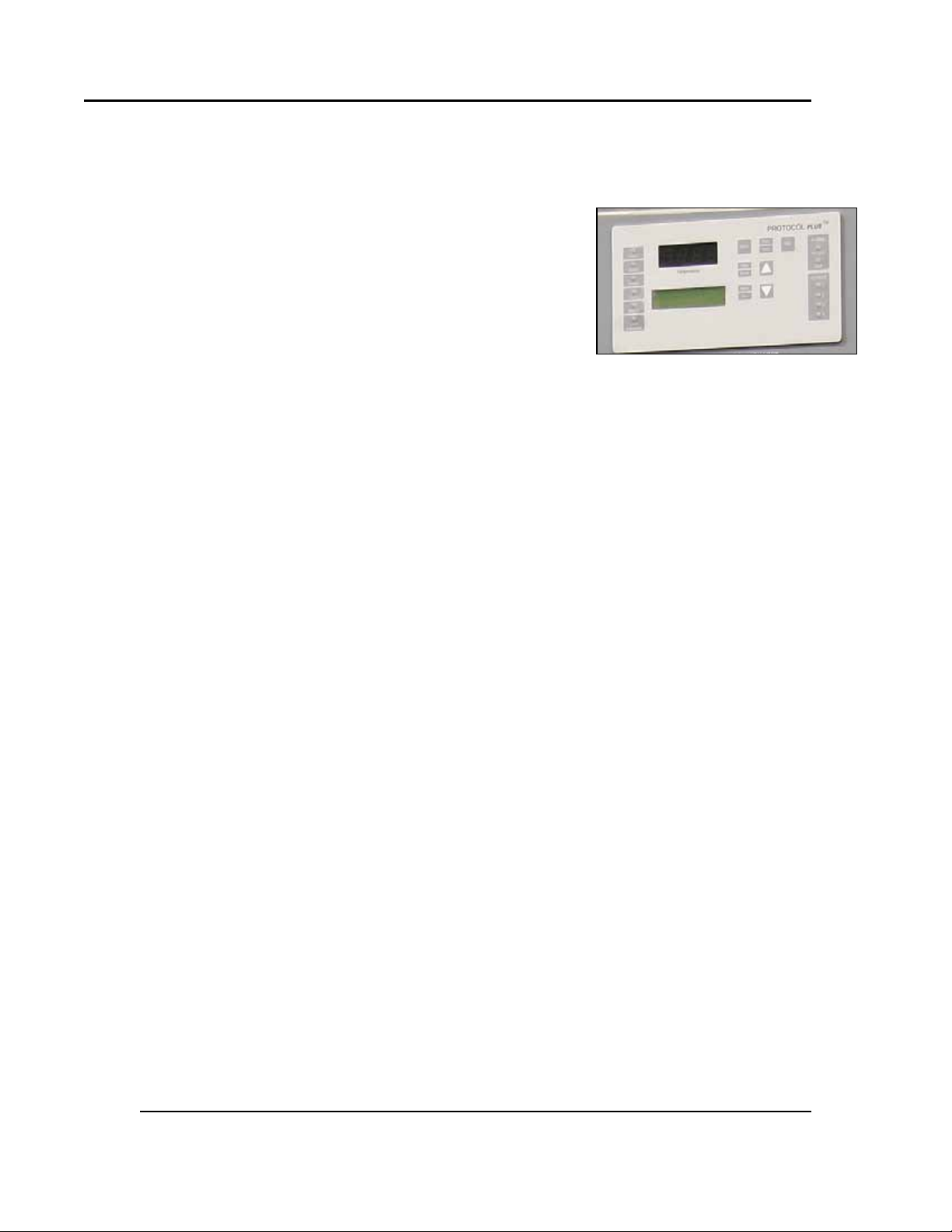
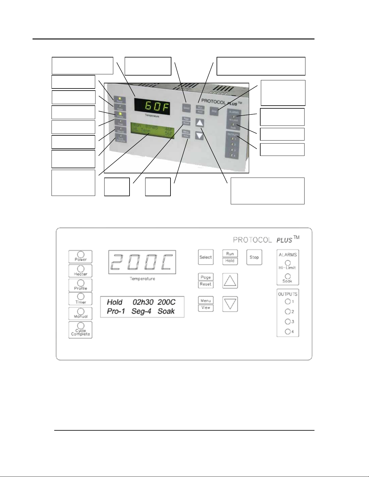
Figure 1. Operator Interface.
12 Version 2
3. Theory of Operation
The Protocol Plus is a modular micro pr ocessor based digital te mperatu r e cont roller
(Figure 1). The Protocol Plus controller operates as a dualfunc tioning controller/high limit instru ment. The control
po rtion u tiliz e s a time -pr oportioning voltage signal to
control heating devices with minimal tempe rature
fluctuations.
The h i gh limit portion protects the product and /or the oven
from overheat ing. If the product being processed has a
critical high te mperat ur e limit, t he high limit setpoint
should be set to a temperatur e somewhat below the
temperature at which the product could be damaged. If the product do es not ha ve a
critical high te mperat ur e limit, t he high limit set p oint s ho uld be set 5 to 15 degrees higher
tha n the maximum programmed setpoint at w hich the ove n will operate.
Th e Prot oc ol Plus controller provides three primary operat ing modes:
• Manual: Oven operates cont inuously at a fixed temperature until turned off.
• Timer: Oven operates at a fixed temperatu r e for a user-selected time period, then
automatically tu r ns off.
• Profile: Temperat u r es increase o r d ecr ease as defined by one of eight pre-
programmable ramp and soak profiles. Each pro file co nt ains up to eight r amp and
soak segments. The profiles can be linked to provide additional temperatur e
combinations.
In addition these primary operating modes, the Protocol Plus controller employs a
Stopped Mode, Auto Start Mode, Setup Mode and Fast Start Mode:
• Stopped Mode: All control and relay outputs are off. Stopped Mode is integrated
into each of the modes of operat ion.
• Aut o Start Mode: C ontrol may au tomat ic ally star t Manual, Timer, or Prof ile
mode based on a preset time and day. Optional event outputs can be util ized
during Manual, Timer, or Profile modes.
• Setup Mode: Provides access to control configuration and programming of
profiles. Set u p Mod e contains ten separate electronic “Pages” where con figuration
and programming para meter s (Menu items) are found and can be manipulated .
• Fast Start Mode: Pro vides for automatic startup of an operating mode w hen
po w er is applied. Use Fast St art Mo d e if the same mode of operation is used every
day. The user can turn on the power and the oven w ill start t he desired process
automatically. The Fast Start Mode is controlled by the Power-Up St a rt
parameters o n the Control page.
All rig hts reserved. No part of the contents of this m an u al m ay b e r ep roduced, copied or t ransmitted in any for m or by any
means including graphic, electronic, or mechanical methods or photocopying, recording, or information storage and
retrieval systems without the writ ten permission of Despatch Industrie s , unless for purchaser's personal use.
Copyright © 2010 by Despatch Industries.
Page 13

Protocol Plus Owner’s Manual THEORY OF OPERATION
Version 2 13
3.1. System Control—In Ge ner a l
• T he Proto col Plus controller provides outputs for the cooling fan, door lock
switch/door release pus hbutton, and optional beacon lig ht
• As many as eight profiles for oven hea ting cycles are stored in the Proto col Plus
controller. Access profiles using the Protocol Plus keypad.
• The Prot oco l Plus cont r ols the solenoid valves in an in ert atmosphere oven for p urg e
and maint ain operat ion
3.1.1. High-Limit Function
The Protocol Plus controller has an integ rated h igh limit function which d is able s the
heater output when t ripped. Find High-Limit temperature readouts on LC D Line #2 in all
Modes (Stop, Run, Hold, and Standby) except Setup Mode. High-Limit temperature is
displayed for 10 seconds, alternating with current Mode and Status display for 10
seconds. The contro l will not allow t he high limit set point to be set below the current
setpo int value.
If the high limit trips, the Hi-Limit indicator w ill light and the relay must be ma nu a ll y
reset. Allow the o ven to cool several degrees (or increase t he high limit set point) and then
press Reset. The indic ator will turn of f.
3.1.2. Optional Serial Communications Hardware
Optional MODBUS RS422/485 serial communications hardware may be installed on the
Protoco l Plus controller, with a 9-pin communicatio ns port located on rear of oven. This
provide s the a bility to netwo rk the oven(s) with a host PC.
3.2.
Display Functions
The Protocol Plus contro ller has t wo displa ys. A dedicated LED upper display shows t he
oven temperatur e (Figure 2). A two line LCD lower display provides information on
control stat u s, high limit temperat ur e and a llows changes to be made to the control
settings. Figure 3 shows a schemat ic of the Protocol Plus face plate.
All rig hts reserved. No part of the contents of this m an u al m ay b e r ep roduced, copied or t ransmitted in an y form or b y an y
Copyright © 2010 by Despatch Industries.
means including graphic, electronic, or mechanical methods or photocopying, recording, or information storage and
retrieval systems without the writ ten permission of Despatch Industrie s , unless for purchaser's personal use.
Page 14
THEORY OF OPERATION Protocol Plus Owner’s Manual
Power
Heater
Profile
Timer
Manual
Cycle
Complete
Oven Temperature
Information
Hi-Limit
Alarm
Outputs 1-4
Adjust parameter
Select mode
of operation
Page
Reset
Menu
View
Run/Hold:Pr ess to activate
mode of operation
Stop: Press
Mode
Figure 2. Protocol Plus Displays and Control Buttons.
Figure 3. Protocol Plus C ontroller Faceplate.
14 Version 2
to Stop any
Soak Alarm
on control
status
settings up or down as
necessary
All rig hts reserved. No part of the contents of this m an u al m ay b e r ep roduced, copied or t ransmitted in any for m or by any
means including graphic, electronic, or mechanical methods or photocopying, recording, or information storage and
retrieval systems without the writ ten permission of Despatch Industrie s , unless for purchaser's personal use.
Copyright © 2010 by Despatch Industries.
Page 15
Protocol Plus Owner’s Manual THEORY OF OPERATION
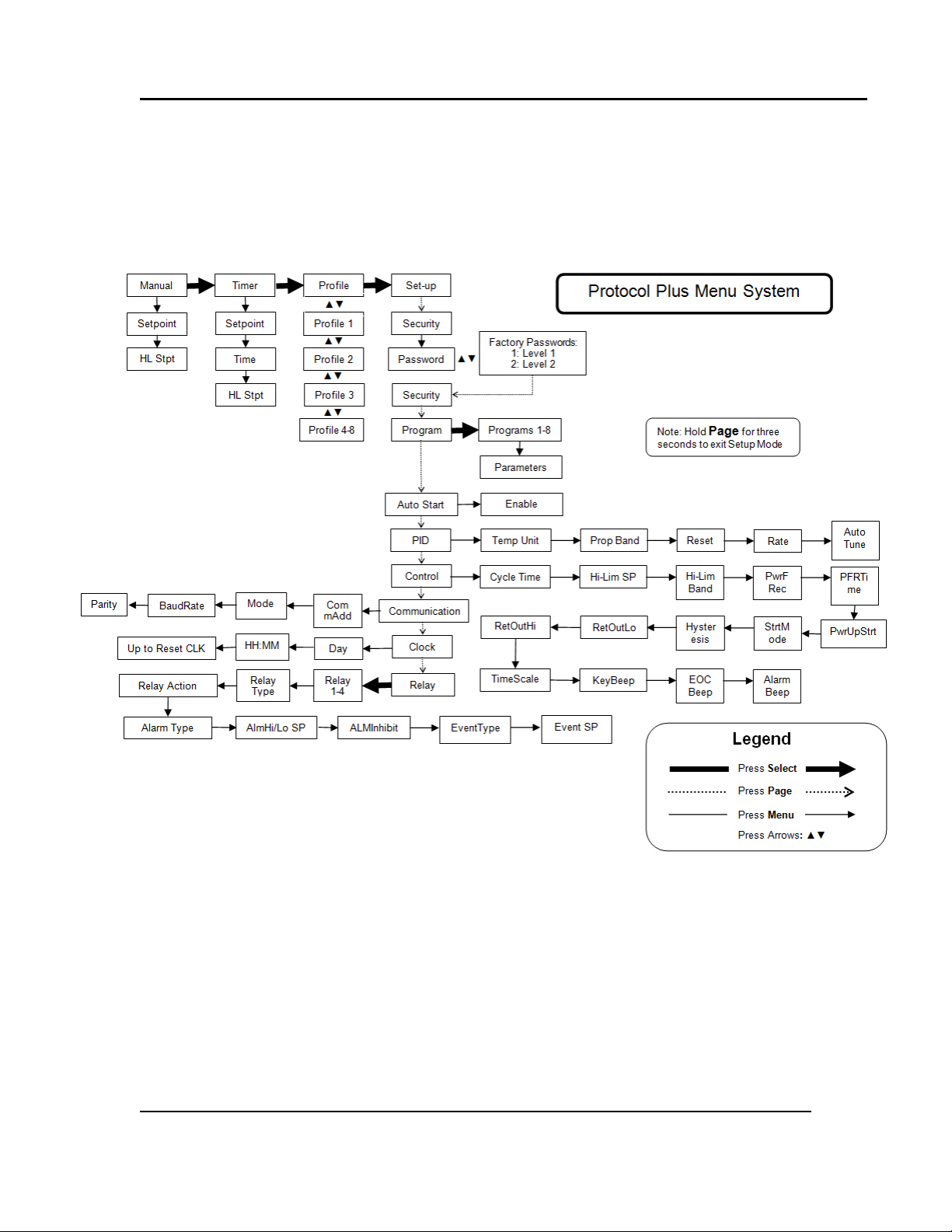
Figure 4. Protocol P lus Menu System—Set up Deta i l
Version 2 15
3.3. Modes and Menus
The Protocol Plus contro ller uses a menu system to display, setup and run the different
modes and configurations available fo r the LCC O ven (Figure 4).
All rig hts reserved. No part of the contents of this m an u al m ay b e r ep roduced, copied or t ransmitted in an y form or b y an y
means including graphic, electronic, or mechanical methods or photocopying, recording, or information storage and
retrieval systems without the writ ten permission of Despatch Industrie s , unless for purchaser's personal use.
Copyright © 2010 by Despatch Industries.
Page 16

THEORY OF OPERATION Protocol Plus Owner’s Manual
16 Version 2
3.4. Indicators
Refer to Figure 2:
• Power LED: Indicates power supplied to instrument
• Heater LED: Indicates heater output active
• Profile L ED: Indicates Pr ofile Mode is in operation
• Timer L ED: Indic a tes Timer Mode is in operat ion
• Manual LED: Indicat es Manual Mode is in operatio n
• Cycle Complete LED: Indicates co nt ro l is in Stopped or Standby modes.
• Hi-Limit Alarm LED: Indicates high limit r e lay has tripped (de-energized).
• S oak Alarm LED: Indicates the guarant eed soak deviation is in alarm condition.
• Outputs 1 through 4: Indicate that the optional relay outputs are in the ON state.
These output s may be configured as timed event outputs, process temperature trip
po int outputs, alar m outputs, or as an end of cycle relay ou tput. T he ON state can be
configured as energ ized or de-energized.
3.5. K ey Fun cti on s
Refer to Figure 2:
• Select: Press to select mode of operat ion. In Set u p Mode, to select profile number or
relay. In Profile/Run Mode, p r ess simulta neo usly with the UP key to advance a
segment.
• Run/Hold: Press to activate a mode of operation. If a Profile (or T imer) Mo d e is
running, pressing the Run/Hold key will place the Profile (or Timer ) in Hold status. A
subsequent press w ill resume the Pr ofile (Timer).
• Stop: Press to stop any mode of operation.
• Page/Reset: While in Setup Mo de, pr ess to access d ifferent P ages of configuration,
Press this key to silence an alarm if the instrument alarm sounds during operation. In
an operating mode, if an alarm or er ror cond it ion occurs, p r ess t his key to retur n the
instrument to normal oper ation once the condition is cleared.
• Menu/View: While running any operating mode, pressing this key will display the high
limit setpoint. While in Setup Mode, pressing this key will provide access to each
Menu parameter.
• ▲▼: Press to adjust parameter settings. In Profile/ Stopp ed Mode, press to select
profile to run. In Prof ile/R un Mode, pr ess ▲ sim ultane ous ly with Select to force the
program to advance one segment .
3.6. Outputs
The Protocol Plus contro ller comes standard with an out put s ignal that can transmit
temperature data to a user-supplied recording device. Opt ional output relays (four) can
also signal user-specified events or alarm to ext er nal devices (Figure 5).
All rig hts reserved. No part of the contents of this m an u al m ay b e r ep roduced, copied or t ransmitted in any for m or by any
means including graphic, electronic, or mechanical methods or photocopying, recording, or information storage and
retrieval systems without the writ ten permission of Despatch Industrie s , unless for purchaser's personal use.
Copyright © 2010 by Despatch Industries.
Page 17
Protocol Plus Owner’s Manual THEORY OF OPERATION
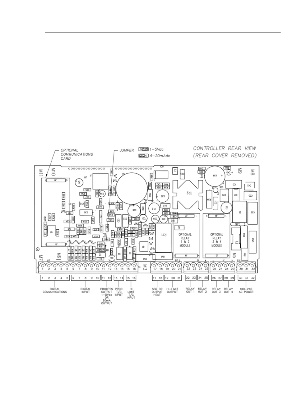
Figure 5. Protocol Plus C ontroller with Rear Cover Removed, Showing Locati ons for Opti onal
Version 2 17
• Heati ng output: The cont rol output is a DC voltage open-collector output which is
time-proport ioned and des igned to control a heat control device such as a solid stat e
relay.
• High limit: The high limit outpu t is a form C relay wh ic h is en erg ized un de r normal
operating condit ions. If t he co ntrol senses a tempe rature highe r t han t he high limit
se tpoint, or if there is a sensor e rr or, the high l imit relay will de-energize until the
condition is cleared and Reset is pressed. When the high limit relay is de-energized,
the he ate r is d is abled.
• Retransmission: The r etransm ission outp ut is a D C 1 to 5 volt or 4 to 20 ma (DC)
signal that is proport ional to the process temperature. The signal can be an input to
other devices such as a chart r eco r der.
• Relay (four optional outputs): T he four form A dry contact r elay output s can be
configured to funct ion as alar ms, event s, or end of cycle. The se o ut p ut s can be
ut ilized in Manual, Timer, or Pro file Modes.
components.
Copyright © 2010 by Despatch Industries.
All rig hts reserved. No part of the contents of this m an u al m ay b e r ep roduced, copied or t ransmitted in an y form or b y an y
means including graphic, electronic, or mechanical methods or photocopying, recording, or information storage and
retrieval systems without the writ ten permission of Despatch Industrie s , unless for purchaser's personal use.
Page 18

ASSEMBLY & SETUP Protocol Plus Owner’s Manual
Danger!
All grounding and safety equipment must be in compliance with
Warning!
18 Version 2
4. Assembly & Setup
applicable codes, ordinances and accepted safe practices.
Disconnect the main power swit ch or power cord before
attempting any rep air o r adjustment.
4.1. Install the Protocol Plus Controller
When replacing a Protocol Plus controller, follow the steps below. Tools required
for installation include ¼” socket set with #1 bit, #2 Philips screwdriver.
1. Disconnect the power.
2. Remove the screws from the sides of the control panel and slide it forward.
3. Unplug all terminals on the rear of the control, noting the proper
connections (
4. Remove the four retaining clips for the control.
5. Remove the control.
6. Insert the new control into the panel.
7. Fasten the four retaining clips.
8. Re-plug all terminals.
9. Fasten the control panel.
Figure 6).
All rig hts reserved. No part of the contents of this m an u al m ay b e r ep roduced, copied or t ransmitted in any for m or by any
means including graphic, electronic, or mechanical methods or photocopying, recording, or information storage and
retrieval systems without the writ ten permission of Despatch Industrie s , unless for purchaser's personal use.
Copyright © 2010 by Despatch Industries.
Page 19

Protocol Plus Owner’s Manual ASSEMBLY & SETUP
Figure 6. Protocol P lus Wi rin g D iagr am.
Version 2 19
4.2. MRC5000 Setup (Optional)
Refer to instruction s pro vid ed reco rder manufacturer for more
O
Temperature is retr ansmitt ed t o t he MRC5000 recorder from t he controller. Set up the
recorder by:
1. Ensure hardware jumper JU1 is in place for t he 5 VDC setting (Refer to MRC5000
Manual included).
2. Move Mode to PROG/TEST/CAL to display Prog.
3. Press ▼ twice to d is pla y Inps. Move to each Parameter Co d e using ▼or ▲. Adjust
each Parameter Code using the setti ngs in Table 1.
4. After adjusting a ll set ti n g s , mov e Mode to RUN. Disp lay on bot h the Recorder and
controller shou ld read t he same.
specific installation notes.
All rig hts reserved. No part of the contents of this m an u al m ay b e r ep roduced, copied or t ransmitted in an y form or b y an y
means including graphic, electronic, or mechanical methods or photocopying, recording, or information storage and
retrieval systems without the writ ten permission of Despatch Industrie s , unless for purchaser's personal use.
Copyright © 2010 by Despatch Industries.
Page 20

ASSEMBLY & SETUP Protocol Plus Owner’s Manual
Parameter Code
Degrees C
Degrees F
Inps
18
18
Icor 0 0
diSP
On
On
dPOS
0 0 EUU
1
400 752
EUL1
0
32
ChUP
400
800
2
ChLO
0
0
DFF
1
1
20 Version 2
Table 1. MRC 5000 Settings.
1
These values must match the settings RetOutLo and RetOutHi on the Protocol Plus Contr ol page. For
example, if RetOutLo is 32, EUL must read 32.
2
Chang e 0 -400 chart paper to 0-800 chart paper. Depending on th e equipment used, 0-600 paper may be
used if the maximum temperature is 500 degrees F.
All rig hts reserved. No part of the contents of this m an u al m ay b e r ep roduced, copied or t ransmitted in any for m or by any
means including graphic, electronic, or mechanical methods or photocopying, recording, or information storage and
retrieval systems without the writ ten permission of Despatch Industrie s , unless for purchaser's personal use.
Copyright © 2010 by Despatch Industries.
Page 21

Protocol Plus Owner’s Manual OPERATION
Version 2 21
5. Working wit h Oper at ing Modes
Users and operators of this controller must comply with
operating procedures and training of operating personnel as
required by the Occupatio nal Safety and Health Act (OSHA) of
O
5.1. Start-up Basics
1970, Section 5 and relevan t safety stand ards, and other safety
rules and regulations of state and local go vernments. Refer to
the relevant safety stand ards in OSHA and National Fire
Protection Associati on (NFPA), Section 86 of 1990.
Configuration controls may need to be changed depending on
O
At initial power -up, control is in Manual/Stopped Mode (unless the Autostart or Fast
Start Modes are active). To activate any o p er ating mode from Manual/Sto p ped Mod e,
press Select until the desired mode is displayed and then pres s Run. If the prop e r Profile
number is not displayed when t he Pro file Mod e is accessed, p r ess
desired Profile number is d ispla yed, then press
(displa y r ea ds None), no profiles ar e cur r ent ly progr ammed. Refer to Section 5.6 for
instructions about setting up profiles.
Note that:
• When the lower LCD display reads HL Temp, the Hi limit ther moco up le actua l
temperature read ing is displa yed. Note that the actual temperature reading is not an
error message.
• T he t emperat ur e setpoint can be adjusted while Manual or Timer Mode is running by
pressing ▲ or ▼.
• T o mo mentarily hold the Timer or Profile Mode, press Hold. To cont inue the Timer
or Profile Mode, press Run.
• To r eturn to St opped Mode at any time, press Stop and the Cycle Complete L ED wil l
illuminate.
Note that the control can be configured to automatically activate Manual, Timer or
Profile Mode when power is applied (power switch turned ON). See Contro l Page in the
Setup Mode to utilize the Fast St art mode (Section 5.6.7).
the mode used. Refer to the specifi c op erat in g instructions
below, for more information.
▲ or ▼ until the
Run. If no profile numbers are displayed
All rig hts reserved. No part of the contents of this m an u al m ay b e r ep roduced, copied or t ransmitted in an y form or b y an y
means including graphic, electronic, or mechanical methods or photocopying, recording, or information storage and
retrieval systems without the writ ten permission of Despatch Industrie s , unless for purchaser's personal use.
Copyright © 2010 by Despatch Industries.
Page 22

OPERATION Protocol Plus Owner’s Manual
22 Version 2
Control can be configu red to auto mat ically activate Manual,
O
5.2. Manual Mode
1. Press Select until Manual displays.
Timer or Profile Mode when po we r is ap plied (power swit c h ON).
Refer to Section 5.5.
Press Run at any time in the procedure to activate Manual Mode.
O
2. Press Menu to display the Pro cess Temperat u r e Setpoint (Setpt). Change Setpoint
(Setpt) by pressing ▲ or ▼.
If the SPChange on the Enable page in Setup Mode ha s been set
to DISABLED, it must be changed to ENABLED befo re any
O
3. Press
4. Optional feature: Press
5. To start Manual Mod e, press Run.
The display changes from Stop to Run. Return to Stopped Mode by pressing Stop. While
in operation, the process set p oint can be adjusted by using ▲ or ▼ to cha nge t he valu e
while the mode is running. Press Menu to display the High Limit Setpoint (HLSP)
setting.
Menu a second time to display curre nt h igh limit setp oint (HLSP). T he valu e
can be adjusted pressing
activated (see Cont rol page, Section 5.6.7) and the high limit cannot be adjusted.
event ON or ▼ to turn the even OFF. Repeat for all event s which are enab led (up to
four eve nts).
O
changes to the process temperature an d high limit setpoints can
be made.
▲ or ▼. If Band displays, the High Limit band feature is
Menu a third time to display Event1. Press ▲ to turn the
Changes to High Limit Setpoint or Eve n t Output Configuration
must be accomplished from the Stop Mode.
All rig hts reserved. No part of the contents of this m an u al m ay b e r ep roduced, copied or t ransmitted in any for m or by any
means including graphic, electronic, or mechanical methods or photocopying, recording, or information storage and
retrieval systems without the writ ten permission of Despatch Industrie s , unless for purchaser's personal use.
Copyright © 2010 by Despatch Industries.
Page 23

Protocol Plus Owner’s Manual OPERATION
Version 2 23
5.3. Timer Mode
1. Press Select until Timer displays.
O
2. Press Menu to display the Pro cess Temperat u r e Setpoint (Setpt). C hange Set point
(Setpt) by using ▲ or ▼ to cha nge t he valu e.
O
Press Run at any time in the procedure to activate Timer Mode.
If the SPChange on the Enable page in Setup Mode ha s been set
to DISABLED, it must be changed to ENABLED befo re any
changes to the process temperature an d high limit setpoints can
be made.
3. Press Menu a second time to display current hig h limit set point (Hi-Lim SP). Change
Setpo int (Hi-Lim SP) using ▲ or ▼. If Band displays, the high limit band feature is
activated (see Cont rol page, Section 8.1.5) and the high limit cannot be adjusted.
4. Press
5. Optional Feature: Press
6. Press Menu a fifth time to display the current gu ar ant eed soak band (TmrGuarSoak)
7. To start Timer Mode, p r ess Run. The d ispla y changes from Stop to Run and the time
Pressing Run/Hold while in Time r Mo d e put s cont ro l in Hold status. The Time r LED will
flash to indicate Hold status. Press Run/Hold key again to continue timing. The Timer
LED will re turn to lit s tatus.
Menu a t hird t ime to display Time Set. Change the time se tting by using ▲ or ▼.
Menu a fourth time to display Event1. Press ▲ to turn the
event ON or ▼ to turn the even OFF. Repeat for all event s which are enab led (up to
four eve nts).
value. If the process temperat u r e deviates from the setpoint by more than this value,
the timer is placed in a Hold condition. T he timer continues whe n the process
temperature falls wit hin range. Reference the Quick Reference and Default Values
section (Section 8.1) for a vailable sett ings.
remaining displays. R eturn to Stopped Mode by pressing Stop. While in operation,
the process setpoint can be adjusted by using ▲ or ▼ to change the value while the
mode is running. Press Menu to disp l ay t he High Limit Setpoint.
All rig hts reserved. No part of the contents of this m an u al m ay b e r ep roduced, copied or t ransmitted in an y form or b y an y
means including graphic, electronic, or mechanical methods or photocopying, recording, or information storage and
retrieval systems without the writ ten permission of Despatch Industrie s , unless for purchaser's personal use.
Copyright © 2010 by Despatch Industries.
Page 24

OPERATION Protocol Plus Owner’s Manual
24 Version 2
5.4. Profile Mode
1. Press Select until Profile is displayed. None may display if a profile has not been
selected or no profiles have bee n enter ed.
2. Press ▲ or ▼ to display the desired profile.
3. Start Profile Mode by pressing Run.
The display w ill chang e from Stop to Run and show segment time rema ining ,
Temperature S et po int, Pro file #, and the current segment number. To return to Stopped
Mode, pr ess Stop.
Press Run/Hold while in Profile Mode puts the cont r ol into Hold.
O
4. To advance to the next segment while running a profile, press Select and ▲ at the
same time.
If Link To is set to Standby in the Prog r am Page, at the End of Program/Pro file,
1. Cycle Complete LED indication goes ON.
2. Controller be e ps if
3. Heater/control output keeps cont ro lling oven t emperature at last Soak setpoint.
4. All events pr ogrammed (if relay cards are installed a nd progr ammed a s an event) fo r
the last Soak Segment st ays act ive.
Press Run/Hold again to continue in Profile Mode. The Profile
LED flashes to indicate Hold status.
End of Cycle beep is enabled.
Ramping down too fast may cause the high limi t relay to trip
unexpectedly if the high limit band feature is used. Avoid
O
trippin g the high limit relay by using a separate cooling profile
(one that does not use the high limit band) and then linking to
that profile to perform rapid cooling.
5.5. Auto Start Mode
Auto Start allows the operato r to start Manual, Timer, or Profile modes automatically at a
preset time and day. See Setting Up Auto Start (Section 5.6.5) for the time, day, and
operating mode sett ings.
If AutoStart is set to No in the Setup menu, AutoStart will not
O
All rig hts reserved. No part of the contents of this m an u al m ay b e r ep roduced, copied or t ransmitted in any for m or by any
means including graphic, electronic, or mechanical methods or photocopying, recording, or information storage and
retrieval systems without the writ ten permission of Despatch Industrie s , unless for purchaser's personal use.
display on the main Menu. If AutoStart is set to Yes in the Setup
menu, AutoStart will display on the main Menu.
Copyright © 2010 by Despatch Industries.
Page 25

Protocol Plus Owner’s Manual OPERATION
including the Enable page. The default security password values
Version 2 25
To activate Auto Start:
1. On Auto Start page, set Enable to Yes.
2. LCD displays Active, current dat e and time
To deactivate Auto Start, on Auto Start page, set Enable to No.
Once Auto Start is activat ed, co nt inue to u se all operat ing modes as you nor mally would.
If an operating mode is running at the time of a preset Auto Start function (provided Auto
Start is activated), the existing operating mode will overr ide the Auto Start function and
the Auto S tart will not turn on.
All processes set to run in Auto St art must be at least one
O
minute long for all Run Modes (Manual, Timer, and Profile) .
5.6. Setup Mode
Use Setup to configure a number of control parameter s. To access Set up , the cont roller
must read Stop.
5.6.1. Enter and Exit Setup Mode
Enter Setup from Stop by:
1. Press Select until Setup displays.
2. Press Page. Security displays.
3. Press Menu. Password displays. Use ▲ or ▼ to enter the proper password and press
Page.
Passwords Protection
The controller has two levels of password protected security.
Level one provides access only to those menu pages ena ble d on
the Enable page. Level two provides access to all menu pages,
O
are 1 for level one and 2 for level tw o.
If an improper password has been entered, the control will
remain at Security. To enter the proper password, press Menu.
All rig hts reserved. No part of the contents of this m an u al m ay b e r ep roduced, copied or t ransmitted in an y form or b y an y
means including graphic, electronic, or mechanical methods or photocopying, recording, or information storage and
retrieval systems without the writ ten permission of Despatch Industrie s , unless for purchaser's personal use.
Copyright © 2010 by Despatch Industries.
Page 26

OPERATION Protocol Plus Owner’s Manual
including the Enable page. The default security password values
26 Version 2
Exit Setup by pressing Page and holding for three seconds.
Access each of individual Setup pages by pressing Page until the desired heading
displays. Press Menu to access Menu parameters. Press ▲ or ▼ to chang e Menu
parameter sett ings. Re fer to the Quick Reference and Default Values Appendix (S ection
8.1) for default a nd a vai lab le settings.
5.6.2. Temperature Scale Conversion
The Protocol Plus contro ller can be operated for either Centigrade or Fahrenheit. The
controller de faults to Centigrade. Chang from Centigrade to Fahre nheit by:
1. Enter Setu p M od e.
a. Press Select until Setup displays.
b. Press Page. Security displays.
c. Press Menu. Password displays. Use ▲ or ▼ to enter the proper password and
press Page.
Passwords Protection
The controller has two levels of password protected security.
Level one provides access only to those menu pages ena ble d on
the Enable page. Level two provides access to all menu pages,
O
are 1 for level one and 2 for level tw o.
If an improper password has been entered, the control will
remain at Security. To enter the proper password, press Menu.
2. Press Page until PID displays.
3. Press Menu. Temp Unit F or Temp Unit C displays.
4. Use ▲ or ▼ to toggle between and choose F and C.
5. Press a nd hold Page for approximately three seconds to exit Set up mode.
5.6.3. Program Page
Use the Program Page to prog r am the heat profiles. Table 16 show s t he me nu items
available. Eight profiles are available with up to eight ramp and soak segments per
profile. See Section 5.6.3.2 for infor mation on working with optional relay outputs.
All rig hts reserved. No part of the contents of this m an u al m ay b e r ep roduced, copied or t ransmitted in any for m or by any
means including graphic, electronic, or mechanical methods or photocopying, recording, or information storage and
retrieval systems without the writ ten permission of Despatch Industrie s , unless for purchaser's personal use.
Copyright © 2010 by Despatch Industries.
Page 27

Protocol Plus Owner’s Manual OPERATION
Version 2 27
5.6.3.1. Using the Program Page
After entering the Pro gr am Page, pr ess Select to reach the pro file you desire to enter/edit.
Press Menu to select the profile. The first p ar ameter displays: Pr ofile #, Segment 1, Ramp
Time. Adjust the value by pressing ▲ or ▼. When the proper value is displayed, pr ess
Menu to continue to the next parameter. Continue using the Menu to view and adjust each
parameter.
If the current seg ment’s ra mp time value is left at 0:00, the next press of Menu advances
to the High Limit Setpoint parameter for that profile (Hi-Lim SP). Continue
entering/verif ying all par ameters until arriving at the last parameter: Guaranteed So ak
Band (Guar Band). After pro perly e ntering all parameter s, pr ess Page to r eturn to the to p
of the Profile Page. Press Select to enter/ edit anot her pro file, press Page to access another
page, or press and hold Page to exit Setup mode.
While editing any profile, press Select to advance the control to
the time value for the next segment , unt il the last segmen t has
O
been reached. This allow s faster edit ing of the profile rather than
pressing Menu to advance past each parameter.
If Link To Pro is set to Standby (Stby) in the Program Page at the end of running a Pro file,
1. Cycle Complete LED indication goes ON.
2. Controller be e ps if End of Cycle beep is enab led.
3. Heater/control output keeps cont ro lling oven t emperature at last Soak setpoint.
4. All events pr ogrammed (if relay cards are installed a nd progr ammed a s an event) fo r
the last Soak Segment st ays act ive.
Run a profile indefinitely by linking the profile to itself.
O
5.6.3.2. Programming Optional Relay Outputs
Optional relay outputs must be configured prior to use. If optiona l relay outp uts a re
installed, configure them as alarms or events on the Relay Outpu ts Page (Section 8.1.8)
before using. If configured as event outputs, these relays can be used as time or
temperature event s.
Check your schemat ic for relay use in your oven, but typical uses for optional rela ys
include:
• R elay 1: Cooling event
All rig hts reserved. No part of the contents of this m an u al m ay b e r ep roduced, copied or t ransmitted in an y form or b y an y
means including graphic, electronic, or mechanical methods or photocopying, recording, or information storage and
retrieval systems without the writ ten permission of Despatch Industrie s , unless for purchaser's personal use.
Copyright © 2010 by Despatch Industries.
Page 28

OPERATION Protocol Plus Owner’s Manual
Menu Item
Display
Description
28 Version 2
• Relay 2: End of cycle relay
• Re lay 3: Optional N2 purge event
• Re lay 4: Optional N2 maint ain e vent
Table 2. Program Page Menu Items and Explanation.
Ramp Time Seg 1
Event 1 Set Value
Event 2 Set Value3
Event 3 Set Value3
Event 4 Set Value3
Soak Temp Seg 1
Soak Time Seg 1
Event 1 Set Value3
Event 2 Set Value3
Event 3 Set Value3
Event 4 Set Value3
High Limit Setpoi nt
Loop From
Pro-1 Seg-1 Ramp Time
3
Pro-1 Seg-1 Ramp Event 1
Event 1 setting for segment 1 ramp of profile
Pro-1 Seg-1 Ramp Event 2
Pro-1 Seg-1 Ramp Event 3
Pro-1 Seg-1 Ramp Event 4
Pro-1 Seg 1 Soak Temp
Pro-1 Seg 1 Soak Time
Pro-1 Seg-1 Soak Even t 1
Pro-1 Seg-1 Soak Even t 2
Pro-1 Seg-1 Soak Even t 3
Pro-1 Seg-1 Soak Even t 4
Ramp time for segment 1 of profile
Event 2 setting for segment 1 ramp of profile
Event 3 setting for segment 1 ramp of profile
Event 4 setting for segment 1 ramp of profile
Soak temperatur e for segment 1 of profile
Soak time for segment 1 of profile
Event 1 setting for segment 1 soak of profile
Event 2 setting for segment 1 soak of profile
Event 3 setting for segment 1 soak of profile
Event 4 setting for segment 1 soak of profile
(Repeat for segments 2-8, until ramp = 00:00)
Profile-1 Hi-Lim SP
Profile-1 Loop From Seg
High limit setpoi nt f or pr ofile
To start a loop action in a profile
4
Loop To
Loop Count
Profile Link
Guaranteed Soak
Profile-1 Loop To S eg
Profile-1 Loop Number
Profile-1 Link To Pro
Profile-1 Guar Band
To end a loop action in a profile
Number of times to execute loop
To jump from this pr ofile to another
Guaranteed soak band f or pr ofile
3
Available only if optional relay outputs are installed (repeat all for Profiles 2-8).
4
Set to Band to use the high limit band feature.
All rig hts reserved. No part of the contents of this m an u al m ay b e r ep roduced, copied or t ransmitted in any for m or by any
means including graphic, electronic, or mechanical methods or photocopying, recording, or information storage and
retrieval systems without the writ ten permission of Despatch Industrie s , unless for purchaser's personal use.
Copyright © 2010 by Despatch Industries.
Page 29

Protocol Plus Owner’s Manual OPERATION
Parameter
Definition and/or Range
Profile #
Eight profil es are available
Segment #
Program recipe segments one through eight. Give each segment its own set
Ramp Time
Time required to mov e ov en temper ature from one setpoint to another.
to the soak temperat ur e.
EV1 through 4
Program from one to four events into the ramp time portion of each segment.
install ed and is programmed for an event.
Soak Temp
Enter the temperat ur e setpoint of a particular segment . The setpoi nt can
range from -18 to 540 °C (0 to 1000 °F).
Soak Time
Enter the durati on of soak. S oak Time c an r ange from 0 to 99: 59.
EV1 through 4
Program from one to four events into the soak portion of each segment.
install ed and is programmed for an event.
Hi Limit SP
Enter the high limit setpoint. If the temperature exc eeds this value, hi-limit
will alarm and shut off the heater.
Loop From
Identify segm ent number to loop from.
Loop To
Identify segm ent number to loop to.
Loop Number
Enter value from 1-99 to preset the number of times to run the loop
established in “Loop From” and “Loop To.”
Link t o Pro
Enter value to instruc t profile in steps to take when the profil e ends. V alues
Val ue 1 – 8: Jump to specified profile
Guaranteed
Enter value that determines if the process temperature has deviated from the
Version 2 29
Table 3. Parameter Definitions and/or Ra ng e s.
of events, ramp and soak tim es and soak temperature.
Values between 0 and 99:59 are allowed.
The Protocol Plus cont r oller stores profile ramp and soak tim es without units.
Times are set as hours and minutes (HH: M M ) or minutes and seconds
(MM:SS). The setpoi nt aut om atically increments fr om the actual temperature
Events typic ally inv olv e ac tuating/disabli ng rel ay s to cl ose/open valves or
perform other r elay -controlled functions.
NOTE: Events actuate only when the controller has the optional relay cards
Soak Band
Events typic ally inv olv e ac tuating/disabli ng rel ay s to cl ose/open valves or
perform other r elay -controlled functions.
NOTE: Events actuate when the controller has the optional relay cards
include:
• STANDBY: Holds temperature setpoi nt while keeping event relay(s) at
last status, actuates cycle relay(s)
• STOP: Turns heater and all relays to OFF status
• HOLD: Holds temper ature setpoint and all relays at last status, at end of
profile
•
setpoint. If the proc ess temperature deviates from the setpoint by more than
the “Guaranteed S oak Band” value, the soak timer is placed in a hold
condition. The timer continues when the process tem peratur e falls within
range.
All rig hts reserved. No part of the contents of this m an u al m ay b e r ep roduced, copied or t ransmitted in an y form or b y an y
means including graphic, electronic, or mechanical methods or photocopying, recording, or information storage and
retrieval systems without the writ ten permission of Despatch Industrie s , unless for purchaser's personal use.
Copyright © 2010 by Despatch Industries.
Page 30

OPERATION Protocol Plus Owner’s Manual
Figure 7. Sample Profile.
30 Version 2
5.6.4. Sample Profile
Figure 7 shows a graphic representation of the samp le profile, whi le Figure 8 s hows the
parameters entered to achieve that profile.
All rig hts reserved. No part of the contents of this m an u al m ay b e r ep roduced, copied or t ransmitted in any for m or by any
means including graphic, electronic, or mechanical methods or photocopying, recording, or information storage and
retrieval systems without the writ ten permission of Despatch Industrie s , unless for purchaser's personal use.
Copyright © 2010 by Despatch Industries.
Page 31

Protocol Plus Owner’s Manual OPERATION
Enable
Autostart
Auto Start
Enable
Enable (yes) or disable (no)
the Autostart function
Sunday
mode
Auto Start Sun
Mode
Set mode on Sunday to
activate
Off, Manual, Timer , Pr o-1 to
Pro-8
Sunday
time
Auto Start Sun
Time
Set time on Sunday for mode
to activate
Monday
mode
Auto Start Mon
Mode
Set mode on Monday to
activate
Off, Manual, Timer , Pr o-1 to
Pro-8
Monday
time
Auto Start Mon
Time
Set time on Monday for mode
to activate
Tuesday
mode
Auto Start Tue
Mode
Set mode on Tuesday to
activate
Off, Manual, Timer , Pr o-1 to
Pro-8
Figure 8. Sample Profile Values.
Version 2 31
5.6.5. Setting Up Auto Start
Auto Start allows the operato r to start Manual, Timer, or Profile modes auto matical ly at a
preset time and day. Table 4 show s the menu items availa ble.
Table 4. Auto Start Menu Parameters and Values.
Menu Item Display Description Range
No, Yes
00:00 to 23:59
00:00 to 23:59
All rig hts reserved. No part of the contents of this m an u al m ay b e r ep roduced, copied or t ransmitted in an y form or b y an y
means including graphic, electronic, or mechanical methods or photocopying, recording, or information storage and
retrieval systems without the writ ten permission of Despatch Industrie s , unless for purchaser's personal use.
Copyright © 2010 by Despatch Industries.
Page 32

OPERATION Protocol Plus Owner’s Manual
Tuesday
time
Auto Start Tue
Time
Set time on Tuesday for mode
to activate
Wednesday
Auto Start Wed
Set mode on Wednesday to
Off, Manual, Timer , Pr o-1 to
Wednesday
time
Auto Start Wed
Time
Set time on Wednesday for
mode to activate
Thursday
mode
Auto Start Thu
Mode
Set mode on Thursday to
activate
Off, Manual, Timer , Pr o-1 to
Pro-8
Thursday
Auto Start Thu
Set time on Thursday for m ode
Friday
mode
Auto Star t Fri
Mode
Off, Manual, Timer , Pr o-1 to
Pro-8
Auto Star t Fri
Time
Set time on Friday for mode to
activate
Saturday
mode
Auto Start Sat
Mode
Set mode on Saturday to
activate
Off, Manual, Timer , Pr o-1 to
Pro-8
Saturday
Auto Start Sat
Set time on Saturday for m ode
32 Version 2
Menu Item Display Description Range
00:00 to 23:59
mode
time
Friday time
time
Mode
Time
Time
activate
to activate
Set mode on Friday to activate
to activate
5.6.5.1. Configure Auto Start
1. Access Setu p Mode.
2. Press Page until Auto Start displays.
3. Press
Menu.
Pro-8
00:00 to 23:59
00:00 to 23:59
00:00 to 23:59
00:00 to 23:59
If the display does not change, the controller may not have the
O
realtime clo ck option.
4. Set
Auto Start Enable to Yes.
5. Using Menu, sc r oll through the o ptions ava ilab l e and press ▲ or ▼ to set the desired
mode for each day of the week. Select from Manual, Timer or Profile 1 through 8.
6. After setting mode, press Menu.
7. Enter the time of day you wish the mode to activate.
8. Continue through the week by pressing Menu, or press Page if changes are complete.
a. One Auto Start mode can be set for each da y of the week.
b. Exit Setup by pressing Page and holding f or three seconds.
c. Press Select until Auto Start displays.
d. Make sure the correct time and day is displayed. If not correct, set time a nd
day to the Real Time Clock Page in the Setup mode.
All rig hts reserved. No part of the contents of this m an u al m ay b e r ep roduced, copied or t ransmitted in any for m or by any
means including graphic, electronic, or mechanical methods or photocopying, recording, or information storage and
retrieval systems without the writ ten permission of Despatch Industrie s , unless for purchaser's personal use.
Copyright © 2010 by Despatch Industries.
Page 33

Protocol Plus Owner’s Manual OPERATION
Proportional
band
Set proportional band for
tuning
Integral
PID
Derivative
Rate
PID Rate In
Sec
Version 2 33
5.6.5.2. Activate Auto Start
1. On Auto Start page, set Enable to Yes.
2. LCD displays Active, current d ate and time
5.6.5.3. Deactivate Auto Start
On Auto Start page, set Enable to No.
Once Auto Start is activat ed, co nt inue to u se all operat ing modes as you nor mally would.
If an operating mode is running at t he time of a preset Auto Start funct ion (pro vided Auto
Start is activated), t he exist ing op er ating mode w ill override the Auto Start function and
the Auto S tart will not turn on.
All processes set to run in Auto St art must be at least one
O
minute long for all Run Modes (Manual, Timer, and Profile).
5.6.6. Setting Up PID Page
The PID Page contains para meter s that control the response to t he setpo int and process
var ia ble inpu t . Table 5 show s the menu items ava ilab l e .
Table 5. PID Page Parameters and Values.
Menu Item Display Description Range
Display units PID Temp Unit Set display units to °C or °F °C or °F
PID Prop Band
reset
AutoTune PID AutoTune Enable auto tuning f unction Di sabl e, Enable
Reset/Rep/Min
Set integral reset for tuning 0.0 to 100 seconds/repeat
Set derivative rate for tuning 0.0 to 500 seconds
5.6.6.1. Access the PID Page
1. Enter Setu p M ode.
2. Press Page u ntil P ID displays.
3. Press Menu.
4. Change parameters by pressing Menu until the desired parameter is displayed. P ress
▲ or ▼ to set the desired value.
1 to 56°C (1 to 100°F)
All rig hts reserved. No part of the contents of this m an u al m ay b e r ep roduced, copied or t ransmitted in an y form or b y an y
means including graphic, electronic, or mechanical methods or photocopying, recording, or information storage and
retrieval systems without the writ ten permission of Despatch Industrie s , unless for purchaser's personal use.
Copyright © 2010 by Despatch Industries.
Page 34

OPERATION Protocol Plus Owner’s Manual
Menu Item
Display
Description
Range
Cycle Time
Control Cycle
Time Sec
Set cycle time in seconds for
control out put
1 to 60 seconds
High limit
setpoint
Control Hi-Lim
SP
Maximum value for all high
limit setpoi nts
MinHiLimSP - MaxHiLimSP
6
High limit
Control Hi-Lim
If=0, high limit setpoint=
Band
Off, 3°C to 11°C (5°F to 20°F)
34 Version 2
5.6.6.2. Setting up Auto Tune
The AutoTune paramet er d isables o r enables the Aut oT u ne function. To use AutoTune:
1. Enter Setup M od e.
2. Press Page k ey until AutoTune displays.
3. Enable Autotune by pressing ▲ .
4. Press Page for three seconds to exit Setup Mode.
5. Cycl e power to the instrument.
6. Set Manual Mode to Run. The display will alternate betw een AutoTune and Manual.
If the Manual Mode setpoint is less tha n 50 degr ees hig her than the actual process
temperature, the AutoT une funct ion creat es an error cond ition. Clear t he error by cooling
the process temperatu r e or increas ing the setpoint until more than 50 degrees bet ween
them. After AutoTune has completed tuning, the AutoTune parameter will disable by
itself.
Cancel AutoTune by pressing STOP. Access the PID page in Setup Mode, and set the
AutoTune parameter to D isable.
5.6.7. Setting up the Control Page
The Control Page contains parameters that control miscellaneous functions. Table 6
shows the menu items available.
5.6.7.1. Access Control Page
1. Enter Setu p M od e.
2. Press Page until Control displays.
3. Press the Menu.
4. Change each parameter by pressing Menu unt il the desired parameter is displayed,
and then press ▲ or ▼ to change the value.
Table 6. Control Page Parameters and Values.
5
band
Band
Control Hi-Lim SP If>0, high
limit setpoi nt= Cont r ol SP6 +
5
High lim it setpo int is a read-on ly item wh ich is calculated on Enable page
6
Inc lude s ramping setpoints during profiles a nd controlled ramp s
All rig hts reserved. No part of the contents of this m an u al m ay b e r ep roduced, copied or t ransmitted in any for m or by any
means including graphic, electronic, or mechanical methods or photocopying, recording, or information storage and
retrieval systems without the writ ten permission of Despatch Industrie s , unless for purchaser's personal use.
Copyright © 2010 by Despatch Industries.
Page 35

Protocol Plus Owner’s Manual OPERATION
Menu Item
Display
Description
Range
Power fail
recovery
Control PwrFRec
Controls response to l oss of
power
Stop, Restart, H old, R esum e
Recovery
Control PFRTim e
Control abort s to Stopped
period longer then set value
00m00s to 99m59s
Powerup
ControlPwrUpStrt
Allows mode to automatically
Disabl e, Enable
Powerup
Start Mode
Control StrtMode
Operating mode for powerup
start
Off, Manual , Timer, Pro-1 to Pro-8
Hysteresis
Control
Hysteresis
Hysteresis for all alarms and
temperature events
1°C to 56°C (1°F to 100°F)
Process
out low
Control
RetOutLo
Process value for retransmit
output = 1VDC
-73°C to 760°C (-100°F to
Process
out high
Control RetOut Hi
Process value for ret r ansmit
output = 5VDC
-73°C to 760°C (-100°F to
Time scale
Control
TimeScale
Time scale setting f or program
and timer mode
hh:mm o r mm:ss
Key press
beep
Control KeyBeep
Internal beeper sounds when
key is pressed
On or Off
End of
cycle beep
Control
EOCBeep
Internal beeper sounds at end
of cycle
On or Off
Alarm beep
Control
AlarmBeep
Internal beeper sounds f or
alarms
On or Off
Version 2 35
time limit
start
enable
mode if power is lost for time
start when power is first
applied
1400°F)
1400°F)
7
5.6.8. Setting up the Communication Page
The Communication Page co nt ains parameters for the communications feature. Table 7
shows the menu items available.
5.6.8.1. Access Communication Page
1. Enter Setu p M od e.
2. Press
3. Press Menu.
O
4. Change each parameter by pressing Menu until the desired parameter is displayed,
and then press ▲ or ▼ to change the value.
7
Power fail recovery time limit is always MM:SS r egardless of time scale setting
All rig hts reserved. No part of the contents of this m an u al m ay b e r ep roduced, copied or t ransmitted in an y form or b y an y
means including graphic, electronic, or mechanical methods or photocopying, recording, or information storage and
retrieval systems without the writ ten permission of Despatch Industrie s , unless for purchaser's personal use.
Page until Communication displays.
If the display does not change, the controller does not have the
commun ic a tion board installe d.
Copyright © 2010 by Despatch Industries.
Page 36

OPERATION Protocol Plus Owner’s Manual
Menu Item
Display
Description
Range
Address
Communication
CommAddr
Sets address node for
control
1 to 247
Mode
Communication
Comm Mode
Turns on/off
communications
OFF, Modbus
Baud Rate
Communication
Baud Rate
Sets interf ac e speed
2400, 4800, 9600,
19.2K, 38.4K
Parity
Communication
Parity
Sets parity for interface
None, Odd, Even
Menu
Item
Display
Description
Range
Day of the
week
Clock
Day
Setting for current day of the
week
Sun, Mon, Tue, Wed, Thu, Fri,
Sat
Time of
day
Clock
Hh:mm
Setting for current time of the
day
00:00 to 23:59
Reset
Clock
clock to entered v alues
Ready, Done
36 Version 2
Table 7. Communication Page Parameters and Values.
5.6.8.2. Setting up the Real Time Clock Page
The real time clock is a seven day, 24-hour clock with battery backup. The Real Time
Clock Page allows an oper ating mode to begin automat ically at a specific time on a
specific day of the week. The rea l time clock feature also for use of the Po wer Failure
Recovery mode Time Limit featur e ( see S ett ing up the Co nt ro l Page Sect ion 5.6.7). Table
8 shows the menu items available.
5.6.8.3. Access Real Time Clock Page
1. Enter Setu p M od e.
2. Press
3. Press
Page until Clock displays.
Menu.
4. Change each parameter by pressing Menu until the desired parameter is displayed,
and then press ▲ or ▼ to change the value.
Table 8. Real Time Cl ock Page Parameters and Value s.
Press the ▲ key to set the
clock
UP to Reset
8
5.6.9. Setting up the Relay Outputs Page
The Relay Outputs Pag e configures the four alarm/event out put s. Each outp ut has a
dedicated indicator light and can be configured as a temperat ur e alarm, profile event, or
end of cycle output. Temperatu r e alarms can be of type process high, pro cess low,
deviation high, deviation low, or deviation band. Table 9 shows the menu items available.
8
If the ▲ key is not pressed, clock values retain original values. The display changes to Done if the clock
is reset.
All rig hts reserved. No part of the contents of this m an u al m ay b e r ep roduced, copied or t ransmitted in any for m or by any
means including graphic, electronic, or mechanical methods or photocopying, recording, or information storage and
retrieval systems without the writ ten permission of Despatch Industrie s , unless for purchaser's personal use.
Copyright © 2010 by Despatch Industries.
Page 37

Protocol Plus Owner’s Manual OPERATION
Menu Item
Display
Description
Range
Type of
relay
Relay 1
RelayType
Set functi on of
relay
Off, Alarm, Cycl, Ev1 to Ev4
Action of
Relay 1
Set coil and
energized Latching)
Type of
alarm
Relay 1
AlarmType
Set alarm type for
relay
High, Low, Plus, Mi nus, B and
Alarm
setpoint10
Relay 1
AlmHi/Lo SP
Setpoint for alarm
-73°C to 760°C (-100°F to 1400°F)
Alarm
deviation10
Relay 1
AlmDevBand
Deviation band for
alarm
1 to 56°C (1 to 100°F)
Inhibit
Relay 1
Inhibits alarm unti l
reached
En or Dis
11
Type of
event
Relay 1
EventType
Set event type for
relay
Time or Temp
Event
setpoint
Relay 1
Event SP
Setpoint for
temperature event
SPLoLim to SPUpLim
Repeat for relay outputs 2-4, if available
Version 2 37
5.6.9.1. Access Relay Outputs Page
1. Enter Setu p M od e.
2. Press Page until Relay displays.
3. Press Select until the desired rela y output is selected.
4. Press Menu.
5. Change each parameter by pressing Menu until the desired parameter is displayed,
and then press ▲ or ▼ to change the value.
6. To configure a specific relay, press Select until the desired relay displays.
If Relay 0 appears, no relays are installed. See relay kit assembly
O
p.n. 144562.
Table 9. Relay Outputs Page Parameters and Values.
relay
10
alarm10
12
13
9
If the relay output has been configured as l atching, the RESET key must be pressed to return the output to
the non alarm stat e once the alarm condit ion has cleared.
10
Appears only for alarm types.
11
Tur ning on the Alarm Inhibit function di sabl es the alarm output on p ower up until t he proc ess
temperature has reached a non alarmi ng co ndition ("safe").
12
Appears only for time or temp er ature event typ es .
13
Appears only for temperature event types.
All rig hts reserved. No part of the contents of this m an u al m ay b e r ep roduced, copied or t ransmitted in an y form or b y an y
means including graphic, electronic, or mechanical methods or photocopying, recording, or information storage and
retrieval systems without the writ ten permission of Despatch Industrie s , unless for purchaser's personal use.
RelayAction
ALMInhibit
Copyright © 2010 by Despatch Industries.
contact state of
relay
"safe" condition is
• NDE (Normally de-energized)
• NE (Normally energized)
• NDEL (Normally de-energized
Latching), NEL (Normally
9
Page 38

OPERATION Protocol Plus Owner’s Manual
he Test Page only for testing the functionality of the control
Menu Item
Display
Description
Range
Heater output
Test HeatOut
Activate SSR output 100%
OFF or
ON
High limit
relay
Test HiLimOut
Activate high limit alarm
(de-energize relay)
OFF or
ON
Relay 1
output
Test Rly1 Out
Energize relay output 1
OFF or
ON
Relay 2
output
Test Rly2 Out
Energize relay output 2
OFF or
ON
Relay 3
output
Test Rly3 Out
Energize relay output 3
OFF or
ON
Relay 4
Test Rly4 Out
Energize relay output 4
OFF or
HiLim Sensor
Test HL Temp
(push and hold up)
Displays sensor reading
14
OFF or
ON
38 Version 2
5.6.10. Setting up the Test Page
The Test Page cont ains paramet er s whic h allow manual cont rol of the heat control and
optional re lay o utputs. Table 10 sho w s the menu items avai lable .
Use t
O
5.6.10.1. Access Relay Outputs Page
1. Enter Setu p M od e.
2. Press Page until Test displays.
3. Press Menu.
4. Change each parameter by pressing Menu until the desired parameter is displayed,
and then press ▲ or ▼ to change the value.
Table 10. Access Relay Outputs Page Parameters and Values.
instrument. Do not operate the oven for proce s ses using the
Test Page.
output
When entering the Test Page, all outputs are automatically set
O
OFF. When exiting the Test Page, all outputs return to their
previous conditio n reg ardl ess of Test Page settings.
5.6.10.2. Setting up the Zone Calibration Page
The Zone Calibration Page allows adjustment of the displayed temperature versus the
actual temperatur e measured b y t he co nt ro l ther moco u ple. This may be des irable in
14
Press ▲ to refresh display.
All rig hts reserved. No part of the contents of this m an u al m ay b e r ep roduced, copied or t ransmitted in any for m or by any
means including graphic, electronic, or mechanical methods or photocopying, recording, or information storage and
retrieval systems without the writ ten permission of Despatch Industrie s , unless for purchaser's personal use.
Copyright © 2010 by Despatch Industries.
ON
Page 39

Protocol Plus Owner’s Manual OPERATION
Menu Item
Display
Description
Range
Zone 1
actual
Zone Cal
Zone1Act
Point at which Zone 1 is set
(center of chamber)
-73°C to 760°C (-100°F to
1400°F)
Zone1
displayed
Zone Cal
Zone1Dis
Desired displayed value for Zone
1 setting
-73°C to 760°C (-100°F to
1400°F)
Zone 2
Zone Cal
Point at which Zone 2 is set
-73°C to 760°C (-100°F to
Zone2
displayed
Zone Cal
Zone2Dis
Desired displayed value for Zone
2 setting
-73°C to 760°C (-100°F to
1400°F)
Factory
calibration
Zone Cal
FactCal
Restores the fact or y calibration
values
Ready or Done (push-key)
Version 2 39
certain conditions wher e the center of the oven chamber is not the same temperatu r e as
the control thermoco up le. T his te mperat ur e d ifferential may occur when the oven is not
allowed to soak at a constant t emperatu r e for long periods of time, or when the oven is
being used at high temperature. Table 11 s hows the menu items a vailable .
5.6.10.3. Access Zone Calibration Page
1. Enter Setu p M od e.
2. Press Page until Zone Cal displays.
3. Press Menu.
4. Change each parameter by pressing Menu until the desired parameter is displayed,
and then press ▲ or ▼ to change the value.
5. Press Page to exit the Zone Calibration Page.
Use Factory Calibrat io n on ly when no calibration instrument is
O
available. Push ▲ to restore factory values.
Table 11. Zone Calibration Page Parameters and Value s.
actual
Zone2Act
15
(center of chamber)
1400°F)
5.6.10.4. Access Factory Calibration Recovery
Factory Calibrat ion Recovery restores the original factory calibration values. This may be
helpfu l if the cal i bration has be en lost a nd a calibr ation inst rument is not r ead ily
available. To use the Facto r y Calibration Recovery feature on ly, bypass t he Zone 1 and
Zone 2 calibration parameters by pressing Menu.
15
Use only when no calibration instrument is a vailable, push ▲ to restore factory values.
All rig hts reserved. No part of the contents of this m an u al m ay b e r ep roduced, copied or t ransmitted in an y form or b y an y
means including graphic, electronic, or mechanical methods or photocopying, recording, or information storage and
retrieval systems without the writ ten permission of Despatch Industrie s , unless for purchaser's personal use.
Copyright © 2010 by Despatch Industries.
Page 40

OPERATION Protocol Plus Owner’s Manual
40 Version 2
5.6.10.5. Adjusting Actual Versus Displayed Parameters
Two points of display calibration (temperature o ffset) are available. The Zone 1 Actual
and Zone 2 Actual parameters are t he t wo temperat ur e points where t he offset is to tak e
effect. These values are ad just able. The Zone 1 and Zone 2 Displayed parameter s ar e the
values the user wishes to have displayed at the Actual temperatur es, and are also
adjustable.
For example, the control is displaying 400°F with the set point being 400°F, but the center
of the oven chamber is actually 395 °F. This can occur du e to oven wall losses and
product loading var iat ions. T he o p er ato r may change the zone calibration so that the
center of t he oven is 400 °F when the display r eads 400°F. I n t his case operate the oven in
manual mode with a setpo int of 400°F. Reco r d the center o f the chamber (as measured
with an independent senso r ) . Access the Zone Calibration Page and enter th is measured
value as the Zone 2 Actual value, with 400 ° as the Zone 2 D ispla yed value.
Zone 1 can be adjusted using the same metho d at a lower temperat u r e. The instrument
will then create a linear offset based o n t he Zone1 and Zone 2 Act u al temperature values.
Note that the oven does not have to be heated to adjust the zone parameters if the zone
values are known based on pr ior experience.
5.6.10.6. Setting up the Sensor Calibration Page
The Sensor Calibration Page has parameters which can change t he inter na l calibration of
the temperatur e sensor input signal. There is a low and high ca libration point for bo th the
co ntrol sensor a nd the high limit senso r. To calibra te the instrument, a llow the contr ol to
warm up for at least 30 minutes.
5.6.10.7. Access Sensor Calibration Page
1. Enter Setu p M od e.
2. Press Page until Sensor Cal displays.
3. Press Menu.
4. Change each parameter by pressing Menu until the desired parameter is displayed,
and then press ▲ or ▼ to change the value.
The c ontrol may ha ve the optiona l process value retransmission output feature. The
output is a 1 to 5VD C s ignal. To calibrat e the ret ransm it signal, t he RetOutLo and
RetOutHi values fro m the Cont r ol Page mu s t be k nown. Bypass calibrating the control
and high l imit s ensor inp ut and access t he retransmit calibration by press ing the Menu
until RetCalLo d ispla ys ( skip step s 4 -17). Table 12 shows the menu items available.
To re-calibrate the instrument:
1. Disco nnect the control and h igh limit s ensor thermocouples.
All rig hts reserved. No part of the contents of this m an u al m ay b e r ep roduced, copied or t ransmitted in any for m or by any
Copyright © 2010 by Despatch Industries.
means including graphic, electronic, or mechanical methods or photocopying, recording, or information storage and
retrieval systems without the writ ten permission of Despatch Industrie s , unless for purchaser's personal use.
Page 41

Protocol Plus Owner’s Manual OPERATION
Version 2 41
2. Connect a calibration instrument with a type J thermoco uple output to the control
sensor input. Allo w the control to warm up at leas t 30 minutes.
3. Access Setu p Mode.
4. Press Page until Sensor Cal displays.
5. Press Menu k ey until Sensor Cal -100F displays.
6. With Ctrl S ens -100F displayed, adjust the calibration instrument to Type J
thermocouple, -100 degrees Fahrenheit output.
7. Wait 30 seconds. Pr e ss ▲.
8. With Ctrl S ens 1400F displayed, adjust the calibration instrument to 1400 degrees
Fahren heit out p ut (Type J thermocouple).
9. Wait 30 seconds. Pr e ss ▲.
10. When Ctrl S ens Done displays, disconnect the cali bration inst ru me nt from the control
sens or input and c onne ct it to the hig h limit se nso r input. Re c onnec t the co ntrol
sensor thermocouple.
11. Press the Menu until HL Sens -100F is displayed.
12. With the cont r ol displaying HL S ens -100F, adjust the calibration instr u ment to -100
degrees Fahrenheit o ut put (T ype J thermocouple).
13. Wait 30 seconds. P ress ▲.
14. With the cont r ol displays HL Sens 1400F, adjust the calibration instrument to 1400
degrees Fahrenheit o ut put (T ype J thermocouple).
15. Wait 30 seconds. P ress ▲.
16. When the contr ol dis pla ys HL Sens Done, disconnect the calibration instrument from
the high limit sens or input. Re-conne c t the high limit senso r thermocouple.
17. To skip calibration of the retransmit signa l, press Page twice to exit the Sensor
Calibration Page.
18. To calibrate the retransmit signal, press Menu until RetCalLo displays.
19. Connect a calibration instru ment with a type J t hermoco uple output to the control
sens or input.
20. Connect a voltage measurement device to the retransmit output ter minals.
21. Set the calibration instrument output to the temperatur e value of the RetOutLo
parameter from the Control Page.
22. Adjust the RetCalLo
16
value by pressing ▲ or ▼ to chang e the value until t he voltag e
measurement d evice reads 1VDC.
23. Press Menu.
24. Set the calibration instrument output to the temperatur e value of the RetOutHi
parameter from the Control Page.
25. Adjust the RetCalHi16 by pressing ▲ or ▼ to change the value of the voltage
measurement d evice to r eads 5VD C.
26. Press Menu.
27. Press Page to ex it the Sensor Calibration Page.
28. Calibration is now complete. Discon nect the calibration instru ment and vo ltage
measurement d evice (if used).
16
The “RetCalLo” and “RetCalHi” valu es are only chan ge indicators. The actual va lue is not meaningful.
All rig hts reserved. No part of the contents of this m an u al m ay b e r ep roduced, copied or t ransmitted in an y form or b y an y
means including graphic, electronic, or mechanical methods or photocopying, recording, or information storage and
retrieval systems without the writ ten permission of Despatch Industrie s , unless for purchaser's personal use.
Copyright © 2010 by Despatch Industries.
Page 42

OPERATION Protocol Plus Owner’s Manual
Menu Item
Display
Description
Range
Control
Ctrl Sens -100F
Calibrat e Sensor Low End
Complete
-100 to 1400°F
HiLim Sensor
HL Sens -100F
Calibrat e HiLim Sensor Low
HiLim Sensor Cal Complete
-100 to 1400°F
Retransmit
RetCalLo XXXX
17
Calibrat e Retransmit Output
High
0 to 4096
42 Version 2
29. Verify that the control and high limit sensor t her mo co uples are connected.
Table 12. Sensor Calibration Page Parameters and Values.
Sensor Cal
Cal
Cal
Ctrl Sens 1400F
Ctrl Sens Done
HL Sens 1400F
HL Sens Done
RetCalHi XXXX
17
Calibrat e Sensor High E nd
Control Sensor Cal
End
Calibrat e HiLim Sensor Hi gh
End
Low
Calibrat e Retransmit Output
-100 to 1400°F
(read only)
-100 to 1400°F
(read only)
0 to 4096
5.6.11. Setting up the Enable Page
The Enable Page contro ls access to the other Setup Pages when Leve l 1 Passwor d is used .
The setpoint minimum and max imum value s, and the security passwords are also set on
the Enable Page. Table 13 show s the menu items a vailable.
5.6.11.1. Access Enable Page
1. Enter Set up Mo de using a level 2 access code (See S ection 5.6 for more on using
access codes).
2. Press Page until Enable displays.
3. Press
4. Change each parameter by pressing
Menu.
Menu until the desired parameter is displayed,
and then press ▲ or ▼ to change t he valu e.
17
The “RetCalLo” and “RetCalHi” valu es are only chan ge indicators. The actual va lue is not mean ingful.
All rig hts reserved. No part of the contents of this m an u al m ay b e r ep roduced, copied or t ransmitted in any for m or by any
means including graphic, electronic, or mechanical methods or photocopying, recording, or information storage and
retrieval systems without the writ ten permission of Despatch Industrie s , unless for purchaser's personal use.
O
Changing Enable to Yes for each page will allow access to the
page in Level 1 security.
Copyright © 2010 by Despatch Industries.
Page 43

Protocol Plus Owner’s Manual OPERATION
Menu Item
Display
Description
Range
Profiles
Enable Profile
1-8
Controls access to Program
Page
Yes or No
Autostart
Enable Auto
Controls access to AutoStart
Yes or No
18
PID Enable PID
Controls access to PID Page
Yes or No
Control
Enable Control
Controls access to Control
Page
Yes or No
Communication
Enable
Communication
Controls access to
Communication P age
Yes or No18
Real Time
Clock
Enable Clock
Controls access to Real Time
Clock Page
Yes or No18
Relay outputs
Enable Relay
Controls access to Relay
Yes or No18
Test
Enable Test
Controls access to Test Page
Yes or No
Zone
Calibration
Enable Zone
Cal
Controls access to Zone
Calibrati on P age
Yes or No
Sensor
Calibration
Enable Sensor
Cal
Controls access to Sensor
Calibration Page
Yes or No
Setpoint lower
limit
Enable
SPLowerLim
Sets minimum setpoint
allowed
-73°C to 759°C (-100°F to
Setpoint upper
limit
Enable
SPUpperLim
Sets maximum setpoint
allowed
-73°C to 760°C (-100°F to
High limit
overhead
Enable
HiLimOH
Sets maximum high limit
setpoint allowed
3 to 11°C (5 to 20°F)
19
Password level
1
Enable
Password 1
Sets password for acc ess
level 1
0 to 999
Password level
2
Enable
Password 2
Sets password for acc ess
level 2
0 to 999
Setpoint
Enable
Set to DISABLE to lock out
and Timer Modes
Yes or No
Analog Output
Type
Enable Analog
Type
Sets Analog Output type
Ctrl or Proc
Version 2 43
Table 13. Enable Page Parameters and Values.
Start
1-4
Page
Page
1399°F)
1400°F)
19
Change
5.6.12. Setting up Digital Inputs (Optional)
The Protocol Plus control can be run by external in puts wire d to the cont rol from an
external source such as a PLC or control panel swi tches (Figure 9). The ext erna l r un
operation can Run, Hold or Stop profiles 1 through 7 (profile 8 cannot be operated
externally). See Table 14 for the inputs required for t he desired o per at ion.
18
If the controller does not ha ve this feature, No is the only option.
19
Maximu m high limit setpo int = SPUpperLim + HiLimOH
All rig hts reserved. No part of the contents of this m an u al m ay b e r ep roduced, copied or t ransmitted in an y form or b y an y
means including graphic, electronic, or mechanical methods or photocopying, recording, or information storage and
retrieval systems without the writ ten permission of Despatch Industrie s , unless for purchaser's personal use.
SPChange
setpoint and high limi t
setpoint changes in Manual
Copyright © 2010 by Despatch Industries.
Page 44

OPERATION Protocol Plus Owner’s Manual
O
Input 1
Input 2
Input 3
Profile Select ed
ON
OFF
OFF
1
OFF
ON
OFF
2
ON
ON
OFF
3
OFF
OFF
ON 4 ON
OFF
ON 5 OFF
ON
ON
6
ON
ON
ON
7
OFF
OFF
OFF
none
Figure 9. Digital Inputs.
44 Version 2
A profile must be created in th e program pag e before trying to
run a profile number.
Table 14. Digital Input Parameters and Values.
• T o start t he selected pro file, set Inputs 1, 2 and 3. The n s et Input 4 to ON.
• T o hold a profile, set Input 4 to OFF.
• T o stop a profile, set all inputs to OFF.
All rig hts reserved. No part of the contents of this m an u al m ay b e r ep roduced, copied or t ransmitted in any for m or by any
means including graphic, electronic, or mechanical methods or photocopying, recording, or information storage and
retrieval systems without the writ ten permission of Despatch Industrie s , unless for purchaser's personal use.
Copyright © 2010 by Despatch Industries.
Page 45

Protocol Plus Owner ’s Manual MAINTENANCE & TROUBLESHOOTING
Global Headquarters
Contact
Service & Technical
Support
Despatch Industries
International/Main: 1-952-469-5424
www.despatch.com
Service: 1-952-469-8230
Alarm Status
Possible Problem
Next Step
Hi-Limit LED flashing
exceeded.
Once the problem has correc ted,
Soak LED flashing
Oven temperat ur e has not
Program a slower ramp rate or if
Top LED displays OPEN
CONTROL SENS ERR
Control thermocouple is
Repair or replace t he
Lower LCD displays HI LIM
Hi limit thermocouple is
Repair or replace t he
Lower LCD displays HIGH
Hi limit temperature setpoint
Determine if:
Err4
Analog to digital c onv er si on
control hardware failure.
Test thermocouple or consult
Err5 (Beep code: five beeps
Program memory fault. Control
Consult factory
Version 2 45
6. Maintenance
6.1. Replacement Parts
To order or return part s, contact the Ser vice Pro duct s Division at Despatch. The Service
Product s features ou r Respo nse Center for cust omer service. When returning parts, a
Despatch represent ative will provide you with an MRA (Material Retur n Aut ho r izat ion)
numb er. Attach t he M RA nu mber to the returned p art for identific ation. When ord ering
parts, expedite your process by providing model number, serial number and part number.
8860 207th Street
Lakeville, MN 55044
USA
US toll free: 1-888-337-7282
Fax: 1-952-469-4513
info@despatch.com
US toll free: 1-800-473-7373
Service @despatch.com
7. Troubleshooting: Error Messages and A larm
Table 15 lists t he more co mmon error messages, t he po ssible prob lems a nd re medies.
Table 15. Err or Messa g e s and Next Steps.
• Probl em with thermocouple
press Reset.
oven is not heating check heater
circuit.
thermocouple.
thermocouple.
and lower LCD displays
SENS ERR
• Hi-limit setpoint has been
entered (or dropped out of ) the
soak band and the soak tim er
has stopped
disconnected or broken
disconnected or broken
LIMIT ALARM
All rig hts reserved. No part of the contents of this m an u al m ay b e r ep roduced, copied or t ransmitted in an y form or b y an y
means including graphic, electronic, or mechanical methods or photocopying, recording, or information storage and
retrieval systems without the writ ten permission of Despatch Industrie s , unless for purchaser's personal use.
has been exceeded
circuit fault. Therm oc ouple or
Copyright © 2010 by Despatch Industries.
• the setting is too close to the
• the SSR is defec tive
• calibration is incorrect
factory
setpoint
Page 46

MAINTENANCE & TROUBLESHOOTING Protocol Plus Owner’s Manual
Alarm Status
Possible Problem
Next Step
in rapid succession)
memory failure.
Batt (Beep code: three
beeps in rapid succession)
Weak or dead battery. Battery
failure.
Consult factory
RTC (Beep code: two
Loss of time in real time cl ock
Reset time in real time cloc k
46 Version 2
beeps in rapid succession)
circuit. Control memory loss .
The lower LC D inte r m it tently display HL Temp. This is not an
O
error message, but the Hi limit thermocouple temperature
reading.
page.
All rig hts reserved. No part of the contents of this m an u al m ay b e r ep roduced, copied or t ransmitted in any for m or by any
means including graphic, electronic, or mechanical methods or photocopying, recording, or information storage and
retrieval systems without the writ ten permission of Despatch Industrie s , unless for purchaser's personal use.
Copyright © 2010 by Despatch Industries.
Page 47

Protocol Plus Owner ’s Manual APPENDICES
Menu Item
Display
Default
Range
Setting
Ramp Time Seg20
Pro-1 Seg-1 Ramp Time
00:00
00m00s to 99h59s
Event 1 Set Value
Pro-1 Seg-1 Ramp Event
Off
Off, On
Event 2 Set Value
Pro-1 Seg-1 Ramp Event
Off
Off, On
Event 3 Set Value
Pro-1 Seg-1 Ramp Event
Off
Off, On
Event 4 Set Value
Pro-1 Seg-1 Ramp Event
Off
Off, On
Soak Temp Seg
Pro-1 Seg 1 Soak Temp
68°F
SPLowerLim to
SPUpperLim21
Soak Time Seg
Pro-1 Seg 1 Soak Time
00:00
00m00s to 99h59s
Event 1 Set Value
Pro-1 Seg-1 Soak Event
Off
Off, On
Event 2 Set Value
Pro-1 Seg-1 Soak Event
Off
Off, On
Event 3 Set Value
Pro-1 Seg-1 Soak Event
Off
Off, On
Event 4 Set Value
Pro-1 Seg-1 Soak Event
Off
Off, On
(repeat for segm ents 2-8)
High Limit Setpoi nt
Pro-1 Hi-Lim SP
Max
MinHiLimSP to
Band22
Loop From
Pro-1 Loop From XX
No
No, Seg-1 to Seg-8
Loop To
Pro-1 Loop To XX
No
No, Seg-1 to Seg-8
Loop Count
Pro-1 Loop Number
0
0 to 99
Profile Link
Pro-1 Link To XX
Stop
Standby23, Stop,
Hold, Pro-1 to Pro-8
Guaranteed Soak
Pro-1 Guar Band
Off
Off, 1 to 778°C
(repeat for profiles 2-8)
Version 2 47
8. Appendices
8.1. Quick Reference and Default Values
8.1.1. Program Page Default Values
Table 16. Program Page Default Values.
20
Cycle Complete LED in dication goes ON.
21
See Enable Page (5.6.11)
22
Band value is set on Control Page (5.6.7)
23
If Standby: (1) Cycle Compl ete LED indication goes ON. (2) Controller beeps if End Of Cycle beep is
enabled. (3) Heater /control output keeps controlling oven temperature at last Soak setpoint. (4) All even ts
progr ammed (if relay cards install ed and programmed as an even t) for the la s t Soak Segmen t s tays active.
All rig hts reserved. No part of the contents of this m an u al m ay b e r ep roduced, copied or t ransmitted in an y form or b y an y
means including graphic, electronic, or mechanical methods or photocopying, recording, or information storage and
retrieval systems without the writ ten permission of Despatch Industrie s , unless for purchaser's personal use.
Copyright © 2010 by Despatch Industries.
HiLimSP
MaxHiLimSP,21
(1400°F)
Page 48

APPENDICES Protocol Plus Owner’s Manual
Menu Item
Display
Default
Range
Setting
Enable Autostart
Auto Start Enable
No
No, Yes
Sunday mode
Auto Start Sun
Mode
Off
Off, Manual, Timer,
Pro-1 to Pro-8
Sunday time
Auto Start Sun Time
00:00
00:00 to 23:59
Monday mode
Auto Start Mon
Mode
Off
Off, Manual, Timer,
Pro-1 to Pro-8
Monday time
Auto Start Mon Time
00:00
00:00 to 23:59
Tuesday mode
Auto Start Tue Mode
Off
Off, Manual, Timer,
Pro-1 to Pro-8
Tuesday time
Auto Star t Tue Tim e
00:00
00:00 to 23:59
Wednesday
mode
Auto Start Wed
Mode
Off
Off, Manual, Timer,
Pro-1 to Pro-8
Wednesday time
Auto Start Wed
Time
00:00
00:00 to 23:59
Thursday mode
Auto Start Thu
Mode
Off
Off, Manual, Timer,
Pro-1 to Pro-8
Thursday time
Auto Star t Thu Time
00:00
00:00 to 23:59
Friday mode
Auto Start Fri Mode
Off
Off, Manual, Timer,
Friday time
Auto Star t Fr i Tim e
00:00
00:00 to 23:59
Saturday mode
Auto Start Sat Mod e
Off
Off, Manual, Timer,
Pro-1 to Pro-8
Saturday time
Auto Start Sat Ti me
00:00
00:00 to 23:59
Menu Item
Display
Default
Range
Setting
Display units
PID Temp U nit
°C
°C or °F
Proportional band
PID Prop Band
6°C
1 to 56°C (1 to 100°F)
Integral reset
PID Reset
2
0 to 100
seconds/repeat
Derivative Rate
PID Rate
0
0 to 500 seconds
AutoTune
PID AutoTune
Disable
Disable, Enable
48 Version 2
8.1.2. Autostart Page Default Values
8.1.3. PID Page Default Values
Pro-1 to Pro-8
All rig hts reserved. No part of the contents of this m an u al m ay b e r ep roduced, copied or t ransmitted in any for m or by any
means including graphic, electronic, or mechanical methods or photocopying, recording, or information storage and
retrieval systems without the writ ten permission of Despatch Industrie s , unless for purchaser's personal use.
Copyright © 2010 by Despatch Industries.
Page 49

Protocol Plus Owner ’s Manual APPENDICES
Profile Name:
Profile Number:
Seg-
Ramp
Soak
Time
Events
Temp-
Time
Events
1 2 3 4 1 2 3
4
Version 2 49
8.1.4. P r ogra mm ing Tabl e Worksheet
ment
erature
1
2
3
4
5
6
7
8
High Limit Setpoi nt
Loop From Seg
Loop To Seg
Loop Number
Link To Profile
Guar Soak Band
All rig hts reserved. No part of the contents of this m an u al m ay b e r ep roduced, copied or t ransmitted in an y form or b y an y
means including graphic, electronic, or mechanical methods or photocopying, recording, or information storage and
retrieval systems without the writ ten permission of Despatch Industrie s , unless for purchaser's personal use.
Copyright © 2010 by Despatch Industries.
Page 50

APPENDICES Protocol Plus Owner’s Manual
Menu Item
Display
Default
Range
Setting
Cycle Time
Control Cycle
Time
1
1 to 60 seconds
High limit setpoint
Control Hi-Lim
SP
Max
HiLimSP
MinHiLimSP – MaxHiLimSP
24
High limit band
Control Hi-Lim
Band
Off
Off, 3°C to 11°C (5°F to 20°F )
Power fail recovery
Control PwrFRec
Stop
Stop, Restart, Hold, Resume
Recovery time limit
Control
PwrFTime
00m00s
00m00s to 99m59s
Powerup start
enable
Control EPwrStrt
Dis
Dis, En
Powerup Start
Mode
Control StrtMode
Off
Off, Manual, Timer , Pr o-1 to
Pro-8
Hysteresis
Control Hyst
3°C
1°C to 56°C (1°F to 100°F)
Process out low
Control RetOutLo
80°C
-73°C to 760°C (-100°F to
1400°F)
Process out high
Control RetOutHi
400°C
-73°C to 760°C (-100°F to
1400°F)
Time scale
Control
TimeScale
hh:mm
hh:mm or mm:ss
Key press beep
Control KeyBeep
On
On or Off
End of cycle beep
Control EOCBeep
Off
On or Off
Alarm beep
Control
AlarmBeep
Off
On or Off
Menu Item
Display
Default
Range
Setting
Address
Communication
CommAddr
1
1 to 247
Mode
Communication
CommMode
OFF
OFF, Modbus
Baud rate
Communication Baud
19.2K
2400, 4800,
38.4K
Parity
Communication Pari t y
None
None, Odd, Even
50 Version 2
8.1.5. Control Page Default Values
8.1.6. Communication (Optional) Page Default Values
24
See Enable Page (5.6.11)
All rig hts reserved. No part of the contents of this m an u al m ay b e r ep roduced, copied or t ransmitted in any for m or by any
means including graphic, electronic, or mechanical methods or photocopying, recording, or information storage and
retrieval systems without the writ ten permission of Despatch Industrie s , unless for purchaser's personal use.
Rate
Copyright © 2010 by Despatch Industries.
9600, 19.2K,
Page 51

Protocol Plus Owner ’s Manual APPENDICES
Menu Item
Display
Default
Range
Setting
Day of the week
Clock Day
Mon
Sun, Mon, Tue,
Wed, Thu, Fri, Sat
Time of day
Clock HH:MM
00:00
00:00 to 23:59
Reset clock
Clock UP to Reset
CLK
Ready
Ready, Done
Version 2 51
8.1.7. Real Time Clock Page Default Values
25
25
If ▲ is not pressed, th e clock will retain original values, the display will change to Done if th e clock is
reset.
All rig hts reserved. No part of the contents of this m an u al m ay b e r ep roduced, copied or t ransmitted in an y form or b y an y
means including graphic, electronic, or mechanical methods or photocopying, recording, or information storage and
retrieval systems without the writ ten permission of Despatch Industrie s , unless for purchaser's personal use.
Copyright © 2010 by Despatch Industries.
Page 52

APPENDICES Protocol Plus Owner’s Manual
Menu Item
Display
Default
Range
Type of relay
Relay 1 RelayType
Off
Off, Alarm, Cycl, Ev1 to Ev4
Action of relay
Relay 1 RelayActi on
NDE
NDE, NE, NDEL, NEL
26
Type of alarm
27
Relay 1 AlarmType
High
High, Low, Plus, Mi nus, B and
Alarm setpoint27
Relay 1 AlmHi/Lo SP
538°C
-73°C to 760°C (-100°F to 1400°F)
Alarm deviati on27
Relay 1 AlmDevBand
3°C
1 to 56°C (1 to 100°F)
Inhibit alarm27
Relay 1 ALMInhibit
On
En or Dis
Ty pe of event
28
Relay 1 EventType
Time
Time or Temp
Event setpoint
29
Relay 1 Event SP
SPUpLim
SPLoLim to SPUpLim
30
(repeat for relay outputs 2-4, if ava ilab le )
52 Version 2
8.1.8. Relay Outputs (Optional) Page Default Values
Press Select to choose relay. If Relay 0 displays, no relays are installed.
26
Norma lly de-energized and non-latching, norm a lly energized and non-latching, normally de-energized
and latching, normally energized a nd latching.
27
Appear s only for alarm types.
28
Appear s only for time or temperature event types .
29
Appear s only for temper ature event types.
30
See enabl e page.
All rig hts reserved. No part of the contents of this m an u al m ay b e r ep roduced, copied or t ransmitted in any for m or by any
means including graphic, electronic, or mechanical methods or photocopying, recording, or information storage and
retrieval systems without the writ ten permission of Despatch Industrie s , unless for purchaser's personal use.
Copyright © 2010 by Despatch Industries.
Page 53

Protocol Plus Owner ’s Manual APPENDICES
Menu Item
Display
Default
Range
Setting
Heater output
Test HeatOut
Off
On High limit relay
Test HiLimOut
Off
On Relay 1 output
Test Rly1 Out
Off
On Relay 2 output
Test Rly2 Out
Off
On Relay 3 output
Test Rly3 Out
Off
On Relay 4 output
Test Rly4 Out
Off
On High Limit Sensor
Test HL Temp
(sensor reading)
Menu Item
Display
Default
Range
Setting
Zone 1 actual
Zone Cal Zone1Act
38°C
-73°C to 760°C (-100°F to
1400°F)
Zone1 displayed
Zone Cal Zone1Dis
38°C
-73°C to 760°C (-100°F to
1400°F)
Zone 2 actual
Zone Cal Zone2Act
260°C
-73°C to 760°C (-100°F to
Zone2 displayed
Zone Cal Zone2Dis
260°C
-73°C to 760°C (-100°F to
1400°F)
Factory
calibration
Zone Cal FactCal
Ready
Ready or Done (push- key)
Menu Item
Display
Default
Range
Setting
Control Sensor
Ctrl Sens 0F
Ctrl Sens Done
-100°F
Done
-100 to 1400°F
(read only)
HiLim Sensor Cal
HL Sens 0F
HL Sens Done
-100°F
Done
-100 to 1400°F
(read only)
Retransmit Cal
RetCalLo XXXX
32
RetCalHi XXXX
0
4096
0 to 4096
0 to 4096
Version 2 53
8.1.9. Test Page Default Values
8.1.10. Zone Cal Page Default Values
8.1.11. Sensor Cal Page Default Values
Cal
31
Use only when no calibration instrumen t is available.
32
The “RetCalLo” and “RetCalHi” valu es are only chan ge indicators. The actual va lue is not mean ingful.
All rig hts reserved. No part of the contents of this m an u al m ay b e r ep roduced, copied or t ransmitted in an y form or b y an y
means including graphic, electronic, or mechanical methods or photocopying, recording, or information storage and
retrieval systems without the writ ten permission of Despatch Industrie s , unless for purchaser's personal use.
1400°F)
31
Ctrl Sens 1000F
HL Sens 1000F
32
Copyright © 2010 by Despatch Industries.
1400°F
1400°F
-100 to 1400°F
-100 to 1400°F
Page 54

APPENDICES Protocol Plus Owner’s Manual
Menu Item
Display
Default
Range
Setting
Profiles
Enable Profile 1-8
Yes
Yes or No
Autostart
Enable Auto Start
No
Yes or No
33
PID
En able P ID
Yes
Yes or No
Control
Ena ble Control
No
Yes or No
Communication
Enable Communication
No
Yes or No
33
Real Time Clock
Ena ble Cloc k
No
Yes or No
33
Relay outputs
Enable Relay 1-4
No
Yes or No
33
Test
Enable Test
No
Yes or No
Zone Calibration
Ena ble Zone Cal
No
Yes or No
Sen sor Cal ibration
Ena ble Sensor Cal
No
Yes or No
Setpoi nt lower limit
Enable SPLowerLim
20°C
-73°C to 759° C (-100° F to
1399°F)
Setpoi nt u p per limit
Ena ble SPU pperLim
260°C
-73°C to 760°C (-100°F to
1400°F)
High l imit overhead
Enable HiLimOH
5°C
3 to 11°C (5 to 20°F)
34
Pas sword l evel 1
Enable Password 1
1
0 to 999
Pas sword l evel 2
Enable Password 2
2
0 to 999
Manual/Timer mode
Enable SPChange
Yes
Yes or No
Analog Output Type
Ena ble Analog Type
Proc
Ctrl or Pr oc
54 Version 2
8.1.12. Enable Page Default Values
setpoint change
33
If the controller does not ha ve this feature, No is the only option.
34
Maximu m high limit setpo int (MaxHiLimSP) = SPUpperLim + HiLimOH. Minimum high limit
setpoint (MinHiLimSP) = SPLowerLim + HiLimOH.
All rig hts reserved. No part of the contents of this m an u al m ay b e r ep roduced, copied or t ransmitted in any for m or by any
means including graphic, electronic, or mechanical methods or photocopying, recording, or information storage and
retrieval systems without the writ ten permission of Despatch Industrie s , unless for purchaser's personal use.
Copyright © 2010 by Despatch Industries.
Page 55

Protocol Plus Owner ’s Manual APPENDICES
Version 2 55
8.2. Standard Products Warranty
All rig hts reserved. No part of the contents of this m an u al m ay b e r ep roduced, copied or t ransmitted in an y form or b y an y
Copyright © 2010 by Despatch Industries.
means including graphic, electronic, or mechanical methods or photocopying, recording, or information storage and
retrieval systems without the writ ten permission of Despatch Industrie s , unless for purchaser's personal use.
Page 56

APPENDICES Protocol Plus Owner’s Manual
56 Version 2
3rdDraft—
Despatch
GLOBAL HEADQUARTERS
Despatch Industries
8860 207th Street West
Minneapolis, MN 55044
USA
US toll free: 1-888-337-7282
international/main: 1-952-469-5424
fax: 1-952-469-4513
info@despatch.com
www.despatch.com
INDUSTRIES
SERVICE AND TECHNICAL SUPPORT
service parts: 1-800-473-7373
international service/main: 1-952-469-8230
service fax: 1-952-469-8193
service@despatch.com
© 2010 Despatch Industries. All rights reserved.
Despatch is a registered trademark of Despatch
Industries in the U.S. and other count ries.
Ransco is a product line of Despatch Industries.
All rig hts reserved. No part of the contents of this m an u al m ay b e r ep roduced, copied or t ransmitted in any for m or by any
means including graphic, electronic, or mechanical methods or photocopying, recording, or information storage and
retrieval systems without the writ ten permission of Despatch Industrie s , unless for purchaser's personal use.
Copyright © 2010 by Despatch Industries.
 Loading...