

Page 1

E-101
P. N. 157427
REVISION B
6/2002
PROTOCOL PLUS™ CONTROL
(HEAT/COOL VERSION)
INSTRUCTION MANUAL
SOFTWARE VERSION 3.1
Prepared by:
Despatch Industries
P.O. Box 1320
Minneapolis, MN 55440-1320
Customer Service 800-473-7373
Page 2

NOTICE
CAUTION
Users of this equipment must comply with operating procedures and training of
operation personnel as required by the Occupational Safety and Health Act (OSHA) of
1970, Section 6 and relevant safety standards, as well as other safety rules and
regulations of state and local governments. Refer to the relevant safety standards in
OSHA and National Fire Protection Association (NFPA), section 86 of 1990.
Setup and maintenance of the equipment should be performed by qualified personnel
who are experienced in handling all facets of this type of system. Improper setup and
operation of this equipment could cause an explosion that may result in equipment
damage, personal injury or possible death.
Dear Customer,
Thank you for choosing Despatch Industries. We appreciate the
opportunity to work with you and to meet your heat processing needs. We
believe that you have selected the finest equipment available in the heat
processing industry.
At Despatch, our service does not end after the purchase and delivery of
our equipment. For this reason we have created the Service Products
Division within Despatch. The Service Products Division features our
Response Center for customer service. The Response Center will direct
and track your service call to ensure satisfaction.
Whenever you need service or replacement parts, contact the Response
Center at 1-800-473-7373: FAX 612-781-5353.
Sincerely,
Despatch Industries
Page 3

Despatch Industries
Product Warranty
See separate warranty for Benchtop and Laboratory Ovens (Form BB7)
Parts, Materials and Labor
Seller warrants the equipment manufactured by Seller and not by others, to be free
from defects in workmanship and material under normal use and service for a
period of (1) year from the date of delivery or the period of two thousand (2,000)
accumulated hours of use, whichever period is shorter. Use or service with
corrosive or abrasive chemicals or materials is not deemed normal. The period of
the foregoing warranty, in the case of furnaces, shall be ninety (90) days or five
hundred twenty-five (525) accumulated hours of use, whichever period is shorter.
Components manufactured by others, including expendable items, are warranted
only in accordance with the warranty, if any, issued by such other manufacturer.
Buyer shall give Seller written notice of any defects with 14 days after discovery
thereof, specifying each particular defect discovered. If such notice is properly
given, Seller will correct without charge any workmanship that is demonstrated to
Seller's satisfaction to have been defective at the time of installation, and will repair
or replace, at Seller's option, without charge, f.o.b. Seller's factory, parts covered by
this warranty that upon inspection are found defective under normal use within the
warranty period above stated. All work of removal and reinstallation, whether or not
found defective, and shipping charges for defective or replacement parts shall be at
the sole expense of Buyer.
The foregoing warranty shall not apply to (i) work done or materials furnished by
others in connection with installation work performed without supervision by Seller's
installation supervisors, or (ii) equipment repaired or altered by others unless such
repairs or alterations were specifically agreed to in writing by an Officer of Seller.
Seller shall not be liable for consequential damages of any kind which occur during
the course of installation of equipment, or which result from the use or misuse by
Buyer, its employees or others of the equipment supplied hereunder, and Buyer's
sole and exclusive remedy against Seller for any breach of the foregoing warranty
or otherwise shall be for the repair or replacement of the equipment or parts thereof
affected by such breach.
The foregoing warranty shall be valid and binding upon Seller if and only if Buyer
loads, operates and maintains the equipment supplied hereunder in accordance
with the instruction manual to be provided upon delivery of the equipment. Seller
does not guarantee the process of manufacture by Buyer or the quality of product to
be produced by the equipment supplied hereunder, and Seller shall not be liable for
prospective profits.
Despatch will repair or replace, at Despatch's option, FOB Despatch's factory, parts
and materials covered by this warranty. Despatch is not responsible for parts or
material failures resulting from misuse, abuse, inadequate preventive maintenance,
acts of nature, or non-conforming utilities, including electrical, fuel supply,
environmental and intake/exhaust provisions. This warranty also does not cover
normal wear or routine maintenance parts and materials expressly designed as
expendable/consumable and replaceable. (Note: Laboratory oven electric heaters
are warranted for a period of five [5] years from date of shipment; three [3] years
from date of shipment for Protocol Plus and DES 2000 temperature controllers.)
Labor services for parts and materials replacement and repair to support this
warranty are available at Despatch's normal service fees. This service is provided
worldwide by a network of factory trained professionals.
Transportation Costs
All transportation costs to transport defective parts or materials to Despatch, and to
transport repaired or replacement parts or materials to Customer, shall be the
responsibility of the Customer.
Terms and Conditions
This Warranty shall be deemed valid and binding upon Despatch if and only if the
Customer:
1. installs, loads, operates, and maintains the covered product supplied hereunder
in accordance with the instruction manual provided upon delivery and product
labeling affixed to the subject equipment:
THE REPRESENTATION AND WARRANTIES SET FORTH HEREIN ARE EXCLUSIVE AND IN LIEU OF, AND CUSTOMER HEREBY WAIVES AND DISCLAIMS
RELIANCE UPON, ALL OTHER REPRESENTATIONS AND WARRANTIES OF EVERY KIND WHATSOEVER, WHETHER EXPRESS OR IMPLIED, OR ARISING BY
OPERATION OF LAW OR IN EQUITY, OR BY COURSE OF PERFORMANCE OR DEALING OR USAGE OF TRADE, INCLUDING, WITHOUT LIMITATION, ANY
IMPLIED WARRANTIES OF MERCHANTABILITY OR OF FITNESS FOR A PARTICULAR PURPOSE.
THIS WARRANTY IS PERSONAL TO THE CUSTOMER AND MAY NOT BE TRANSFERRED OR ASSIGNED. ALL LIMITATIONS HEREUNDER, HOWEVER, SHALL BE
BINDING ON ALL SUCCESSORS AND ASSIGNS OF CUSTOMER.
2. if applicable, follows the Emergency Procedure set forth in this Warranty; and
3. contacts Despatch's Helpline at 1-800-473-7373 for assistance in diagnosing
and troubleshooting the problem immediately upon discovering any damage or
malfunction.
Despatch's reasonable determination as to whether a repair, replacement, or
service is covered by this Warranty shall be final and binding.
Exclusions
This Warranty DOES NOT cover:
1. damage or malfunctions, or expenses incurred in the process of diagnosing
and/or repairing damage or malfunctions, resulting from any of the following:
operator error, misuse, abuse, inadequate preventive maintenance, normal wear
and tear, service or modifications by other than Despatch authorized technicians,
use of the covered product that is inconsistent with the operation manual or
labeling, acts of nature (including, without limitation, floods, fire, earthquake, or
acts of war or civil emergency), internal or external corrosion, or non-conforming
utilities (including, without limitation, electrical, fuel supply, environmental and
intake/exhaust installations);
2. repair or replacement of parts or materials designed and intended to be
expendable or consumable;
3. routine maintenance; or
4. labor costs incurred for troubleshooting, diagnostics, or testing (except for testing
required to verify that a covered defective part or material has been repaired).
Limitations of Liability
Despatch shall not, in any event, be liable for indirect, special, consequential,
incidental, or punitive damages or penalties of any kind, including, without limitation
loss of revenue, profits or business opportunities resulting from interruption of
process or production. In no event shall Despatch be liable for damages in excess
of the amounts paid by Customer to Despatch with respect to the applicable
product(s). This Warranty does not cover, and Despatch shall not be liable for any
losses, costs, damages or expenses resulting from delays in diagnosing or
repairing the products, supplying or obtaining replacement parts or materials,
strikes, labor stoppages or shortages, fires, accidents, government acts or
regulations, or any other causes beyond the control of Despatch.
Non-Compliance By Customer
Despatch reserves the right to suspend and withhold service under this Warranty in
the event of non-compliance by the Customer to any terms and conditions of this
Warranty or the applicable purchase order or invoice. Further, Despatch shall not
be liable for any loss of production, expenses, and inconveniences incurred due to
such suspension.
Customer Furnished Equipment Warranty Limitation
This Warranty does not cover diagnosis or repairs of defects in or caused by, lack
of performance of, or fitness for purpose of customer-supplied parts or equipment
unless specifically noted in the Despatch written order acceptance confirmation.
Performance Commitment
Despatch provides no guarantee of process performance or fitness for purpose,
unless specifically noted otherwise in Despatch written order acceptance
confirmation. Despatch is providing equipment with design parameters specific only
to its equipment.
Procedure Upon Discovery of Defects and Emergencies
In the event Customer becomes aware of any defect in the applicable products,
Customer must immediately: (a) shut off fuel or energy supply (gas and electricity),
(b) call for emergency assistance, if needed, and (c) notify Despatch Service.
Worldwide Phone 612-781-5356; Worldwide Fax 612-781-5485; North American Phone 800-473-7373
Service
e-mail info@despatch.com; www.despatch.com
Please see reverse side for other service offerings BB5 (5/28/02)
Page 4

Despatch Industries
Advantage Service Assurance Program (ASAP)
CONTACT: DESPATCH SERVICE AGREEMENTS SPECIALIST at 800-473-7373 or 612-781-5356
or e-mail: info@despatch.com
Despatch continues to deliver exceptional products backed by a strong sense of responsibility and drive for long term customer
satisfaction. Your partnership with Despatch can offer even higher value through your subscription to one of Despatch's Advantage
Service Assurance Program (ASAP).
Warranty
Despatch's exclusive, comprehensive service programs start with the 1 year parts only warranty which is described on the other
side of this document. This warranty can be expanded immediately to meet your most stringent service needs. Despatch Service
Products Group will be able to answer your service questions and provide a quotation for the immediate expansion of your product
warranty. Call 800-473-7373 or 612-781-5356; or e-mail info@despatch.com.
Immediate Service Response
The key to an effective service program is response. Wherever your location, Despatch is only a phone call away. Our U.S. and
Canadian customers can reach Despatch at 1-800-473-7373. Worldwide customers can call 1-612-781-5356 or FAX
1-612-781-5485. Our Customer Service Technicians have over 150 years combined experience and access to detailed design and
manufacturing documentation specific to your Despatch unit(s). This exacting level of service is a benefit only Despatch can provide
and means that you can expect speedy, accurate and the most cost effective response.
Field Service Network
A worldwide network of factory trained Service Professionals is available to support your Despatch equipment. From routine repair
to certified instrument calibration, the Despatch service network is positioned to respond to your needs. As a manufacturer of
custom equipment, our service programs are customized to meet your specific needs regarding:
1. Service scope
2. Response time
3. Preventive maintenance frequency and content
4. Payment method
Sustained Service Support
At Despatch, long term customer satisfaction means more than just responding quickly and effectively to our customers' service
needs. It means offering comprehensive customer support well beyond the scope and duration of our initial warranty. Despatch
offers two basic service packages which are customized to each individual customer's need. These service packages are titled Full
Service and Preventive Maintenance Plus+ service agreement products. Each is unique in the industry and offer the following
benefits:
1. Priority response for minimum production interruption
2. Preventive maintenance for longer product life
3. Discounts on parts and services
4. Various payment plans to ease budgeting and recording expenses
5. Reduce purchase ordering costs
Worldwide Phone 612-781-5356; Worldwide Fax 612-781-5485; North American Phone 800-473-7373
e-mail info@despatch.com; www.despatch.com
Service
Page 5

TABLE OF CONTENTS
TABLE OF CONTENTS................................................................................................... i
INTRODUCTION.............................................................................................................1
Theory of Control Operation........................................................................................1
Operating Modes......................................................................................................3
Setup Mode..............................................................................................................3
Fast Start Mode........................................................................................................3
High Limit.................................................................................................................4
Indicators .................................................................................................................4
Displays ...................................................................................................................5
Key Functions..........................................................................................................5
Outputs ....................................................................................................................6
Relay (Continued)....................................................................................................7
Communication........................................................................................................7
Optional Software.....................................................................................................7
INSTRUCTIONS .............................................................................................................8
Start-Up.......................................................................................................................8
Operation.....................................................................................................................9
Manual Mode...........................................................................................................9
Timer Mode............................................................................................................10
Profile Mode...........................................................................................................11
Auto Start Mode.....................................................................................................11
Setup Mode............................................................................................................12
Instructions for Setup Mode Pages............................................................................13
Program Page........................................................................................................13
Profile # ..............................................................................................................15
Sample Profile........................................................................................................16
Auto Start Page (optional)......................................................................................17
Control Page..........................................................................................................20
Communication Page (optional).............................................................................21
Real Time Clock Page (optional)............................................................................21
Relay Outputs Page (optional)...............................................................................22
Test Page...............................................................................................................23
Zone Calibration Page ...........................................................................................24
Sensor Calibration Page........................................................................................26
Enable Page...........................................................................................................28
Digital Inputs (optional) ..........................................................................................29
Error Messages and Alarms ......................................................................................30
Quick Reference and Default Values.........................................................................31
Technical Specifications............................................................................................38
APPENDIX: Temperature Scale Conversion and Optional MRC5000 Setup................39
Temperature Scale Conversion (C/F)........................................................................39
i
Page 6

ii
Page 7

INTRODUCTION
The special features of the Protocol PlusTM control include:
• PID tuning
• Ramp/Soak programming of up to 64 segments
• Segment looping and profile linking
• Built-in manual reset high limit control
• Built-in process timer
• Dedicated LED display for process temperature
• Multi-purpose two-line LCD display with backlight
• Auto-tuning
• Security access
• Digital inputs for remote profile control
• Optional relay outputs for events, alarms, or end-of-cycle signal
• Optional real-time-clock
• Optional RS232/RS422/RS485 MODBUS communications
Theory of Control Operation
The Protocol Plus is a modular microprocessor based digital temperature controller. The
Protocol Plus operates as a dual functioning controller/high limit instrument. The control
portion utilizes a time-proportioning voltage signal to control heating devices with
minimal temperature fluctuations.
The high limit portion protects the product and/or the oven from overheating. If the
product being processed has a critical high temperature limit, the high limit setpoint
should be set to a temperature somewhat below the temperature at which the product
could be damaged. If the product does not have a critical high temperature limit, the
high limit setpoint should be set 5 to 15 degrees higher than the maximum programmed
setpoint at which the oven will operate.
1
Page 8
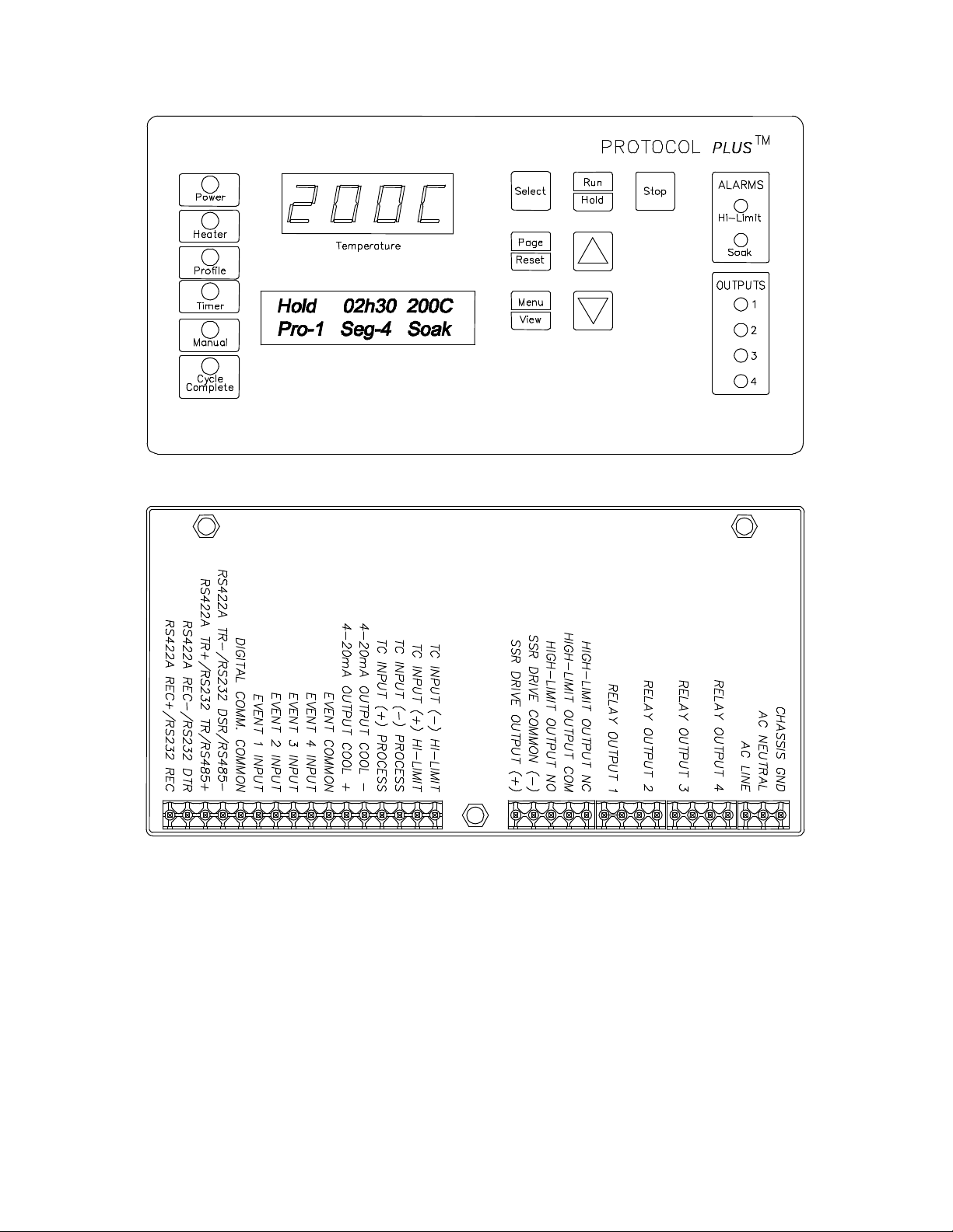
Protocol Plus Faceplate and Wiring Diagram
2
Page 9

Operating Modes
The Protocol Plus control has five modes of operation available:
Stopped Mode: All control and relay outputs are off. Stopped Mode is integrated
into each of the following four modes of operation.
Manual Mode: Control operates as a single setpoint control until Stopped mode is
accessed
Timer Mode: Control operates as a single setpoint control until preset time period
has expired.
Profile Mode: Control operates as a ramp/soak profiling control until the end of
the profile. 8 profiles are available with up to 8 ramp/soak segments
in each profile.
Auto Start Mode (optional): Control may automatically start Manual, Timer, or
Profile mode based on a preset time and day.
Requires the optional real-time clock feature.
The optional event outputs can be utilized during Manual, Timer, or Profile modes.
Setup Mode
The control has a Setup Mode which provides access to control configuration and
programming of profiles. The Setup Mode contains ten separate electronic Pages where
the configuration and programming parameters (Menu items) are found. The Setup
Mode Pages are described in detail elsewhere in this manual.
Fast Start Mode
The Protocol Plus control has the ability to automatically start an operating mode when
power is applied. This feature may be useful if the same mode of operation is used
everyday. The user can turn on the power and the oven will start the desired process
automatically. The Fast Start Mode is controlled by the Power-Up Start parameters on
the Control page (see Setup Mode).
3
Page 10

High Limit
The control has an integrated high limit function which will disable the heater output
when tripped. If the high limit does trip, the relay will need to be manually reset. When
the high limit relay is tripped, the Hi-Limit indicator will be lit. Allow the oven to cool
several degrees (or increase the high limit setpoint) and then press the Reset key. The
indicator will turn off.
The control will not allow the high limit setpoint to be set below the current setpoint
value.
Indicators
The Protocol Plus control has 12 indicating LEDs that provide operational information to
the user.
C Power LED: Indicates that power is supplied to the instrument.
C Heater LED: Indicates that the heater output is active.
C Profile LED: Indicates that the Profile Mode is in operation.
C Timer LED: Indicates that the Timer Mode is in operation.
C Manual LED: Indicates that the Manual Mode is in operation.
C Cycle Complete LED: Indicates that the control is in Stopped mode.
C Hi-Limit Alarm LED: Indicates that the high limit relay has tripped (de-energized).
C Soak Alarm LED: Indicates that the guaranteed soak deviation is in alarm
condition.
C Outputs 1 through 4: Indicate that the optional relay outputs are in the ON state.
These outputs may be configured as timed event outputs, process temperature trip
point outputs, alarm outputs, or as an end of cycle relay output. The ON state can
be configured as energized or de-energized.
4
Page 11

Displays
The Protocol Plus control has two displays. A dedicated LED upper display shows the
oven temperature. A two-line LCD lower display provides information on control status
and allows changes to be made to the control settings.
Key Functions
The Protocol Plus control has seven keys that provide operation.
• Select key: Press to select mode of operation. In Setup Mode, to select profile
number or relay. In Profile/Run Mode, press simultaneously with the UP key to
advance a segment.
• Run/Hold key: Press to activate a mode of operation. If a Profile (or Timer)
Mode is running, pressing the Run/Hold key will place the Profile (or Timer) in
Hold status. A subsequent press will resume the Profile (Timer).
• Stop key: Press to stop any mode of operation.
• Page/Reset key: While in Setup Mode, press to access different Pages of
configuration, Press this key to silence an alarm if the instrument alarm sounds
during operation. In an operating mode, if an alarm or error condition occurs,
press this key to return the instrument to normal operation once the condition is
cleared.
• Menu/View key: While running any operating mode, pressing this key will
display the high limit setpoint. While in Setup Mode, pressing this key will provide
access to each Menu parameter.
• keys: Press these keys to adjust parameter settings. In Profile/Stopped
Mode, press to select profile to run. In Profile/Run Mode, press key
simultaneously with the Select key to force the program to advance one
segment.
5
Page 12
Outputs
The Protocol Plus control has seven different outputs available.
• Heating output: The control output is a DC voltage open-collector output which
is time-proportioned and designed to control a heat control device such as a solid
state relay.
• Cooling output: The cooling output is a 4 to 20 ma DC output which is designed
to control a cooling device such as a damper motor.
• High limit: The high limit output is a form C relay which is energized under
normal operating conditions. If the control senses a temperature higher than the
high limit setpoint, or if there is a sensor error, the high limit relay will de-energize
until the condition is cleared and the Reset key is pressed. When the high limit
relay is de-energized, the heater is disabled.
• Relay (four optional outputs): The four form A dry contact relay outputs can be
configured to function as alarms, events, or end of cycle. These outputs can be
utilized in Manual, Timer, or Profile Mode.
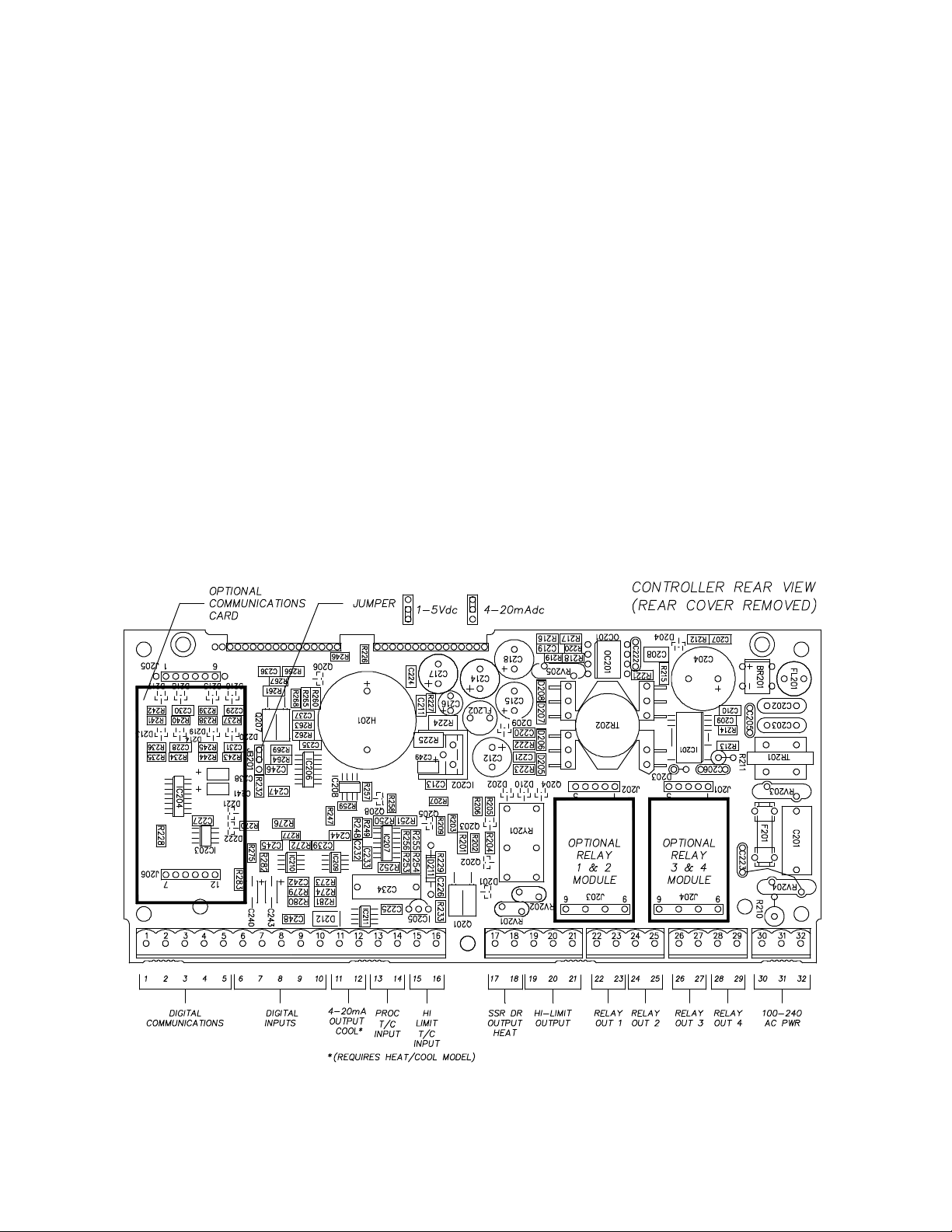
Layout for Optional Components
6
Page 13

Relay (Continued)
Use the Relay Card Optional Ay p/n 144562 to add relays to the standard controller.
Each relay card contains two relays (maximum of two cards Ay’s allowed).
Communication
The Protocol Plus control has optional MODBUS communication available which can
communicate via RS232, RS422, or RS485 to a computer. See communications option
assembly p/n 161957 for board and cable assembly. Please refer to the MODBUS
communications manual which comes with this option.
Optional Software
The Protocol Manager program allows the operator to start/stop multiple ovens (32
maximum) from a personal computer. A data log can also be used to record process
information (p.n. 140008).
7
Page 14

INSTRUCTIONS
Start-Up
These instructions are provided as a quick reference for operating the Protocol Plus
control. If the Profile Mode is to be used, or the configuration of the control needs to be
changed, please refer to the Setup Mode instructions before operating the control. For
more detailed operating instructions refer to the Operation instructions for the mode you
wish to use.
Upon initial power-up the control is in Manual/Stopped Mode (unless the Autostart or
Fast Start Modes are active). To activate any operating mode from Stopped Mode,
press the Select key until the desired mode is displayed, then press the Run key. If the
proper Profile number is not displayed when the Profile Mode is accessed, press the
or keys until the desired Profile number is displayed, then press the Run key. If no
profile numbers can be displayed (display only reads NONE) then no profiles are
currently programmed (see Setup Mode).
The temperature setpoint can be adjusted while Manual or Timer Mode is running by
pressing the UP or DOWN key.
To momentarily hold the Timer or Profile Mode, press the Hold key. To continue the
Timer or Profile Mode, press the Run key.
To return to Stopped Mode at any time, press the Stop key and the cycle complete LED
will illuminate.
Note that the control can be configured to automatically activate Manual, Timer or
Profile Mode when power is applied (power switch turned on). See Control Page in the
Setup Mode to utilize the Fast Start mode.
8
Page 15

Operation
Manual Mode
Press the Select key until Manual is displayed (note you can press the Run key at any
time to activate Manual Mode).
1. Press the Menu key to display the Process Temperature Setpoint (setpt). You
can change the Setpoint with the keys.
Note: If the SPChange parameter on the Enable page in Setup Mode has been
set to DISABLED, it must be changed to ENABLED before any changes to the
process temperature and high limit setpoints can be made.
2. Press the Menu key a second time to display current high limit setpoint (Hi-Lim
SP). The value can be adjusted by pressing the keys. If Band is displayed,
the high limit band feature is activated (see Control page) and the high limit can
not be adjusted.
3. (optional feature) Press the Menu key a third time to display Event1. Press the
key to turn on the event or to turn off the event. Repeat for all events which
are enabled (up to 4).
4. To start Manual Mode, press the Run key.
The display will change from Stop to Run. To return to Stopped Mode, press the
Stop key. While in operation, the process setpoint can be adjusted by using the
keys to change the value while the mode is running. Pressing the Menu key
will display the High Limit Setpoint (HLSP) setting.
If changes to the high limit setpoint or event output configuration are needed, they must
be done from the stopped mode.
9
Page 16

Timer Mode
1. Press the Select key until Timer is displayed (note you can press the Run key at
any time to activate Timer Mode).
2. Press the Menu key to display the Process Temperature Setpoint (Setpt). You
can change the Setpoint with the keys.
Note that if the SPChange parameter on the Enable page in Setup Mode has
been set to DISABLED, it must be changed to ENABLED before any changes to
the process temperature and high limit setpoints can be made.
3. Press the Menu key a second time to display current high limit setpoint (Hi-lim
SP). The value can be adjusted by pressing the keys. If Band is displayed,
the high limit band feature is activated (see Control page) and the high limit can
not be adjusted.
4. Press the Menu key a third time to display Time Set. You can change the time
setting with the keys.
5. (optional feature) Press the Menu key a fourth time to display Event1. Press the
key to turn on the event or to turn off the event. Repeat for all events which
are enabled (up to 4).
6. Press the Menu key a fifth time to display the current guaranteed soak band
(TmrGuarSoak) value. If the process temperature deviates from the setpoint by
more than this value, the timer is placed in a hold condition. The timer continues
when the process temperature falls within range. Reference the Quick
Reference and Default Values section for available settings.
7. To start Timer Mode, press the Run key.
The display will change from Stop to Run and the time remaining will be
displayed. To return to Stopped Mode, press the Stop key. While in operation,
the process setpoint can be adjusted by using the keys to change the value
while the mode is running. Pressing the Menu key will display the High Limit
Setpoint.
Pressing the Run/Hold key while the Timer Mode is in operation will put the control in
Hold status. The Timer LED will flash to indicate the held status. Press the Run/Hold
key again to continue timing. The Timer LED will return to lit status.
10
Page 17

Profile Mode
1. Press the Select key until Profile is displayed. “None” may be displayed if a
profile has not been selected or no profiles entered.
2. Press the key to display the desired profile to run.
3. To start Profile Mode, press the Run key.
The display will change from Stop to Run and the segment time remaining,
Temperature Setpoint, Profile #, along with the current segment number, will be
displayed. To return to Stopped Mode, press the Stop key.
Pressing the Run/Hold key while the Profile Mode is in operation will put the control in
Hold status. Press the Run/Hold key again to continue the mode. The Profile LED will
flash to indicate the hold status.
To advance to the next segment while running a profile, press the Select and UP arrow
keys at the same time.
Note that ramping down too fast may cause the high limit relay to trip unexpectedly if
the high limit band feature is used. This can be avoided by using a separate cooling
profile that does not utilized the high limit band and then jumping to that profile to
perform rapid cooling.
Auto Start Mode
The Auto Start Mode allows the control to start Manual, Timer, or Profile mode
automatically at a preset time and day. See the Auto Start Page in Setup Mode for the
time, day, and operating mode settings. The Auto Start Mode requires the optional Real
Time Clock feature for operation.
To activate the Auto Start Mode, the control must first be in Stopped Mode.
1. Press the Select key until Auto Start is displayed.
2. Press the Menu key.
3. Press the keys to activate or deactivate the Auto Start feature.
Note that once you activate Auto Start, you can continue to use all operating modes as
normal. If an operating mode is running at the time of a preset Auto Start function, and
Auto Start is activated, the existing operating mode will override the auto Start function
and the Auto Start will not turn on.
To use the Auto Start for the next day, the auto start must show in the LCD display that
it is active.
11
Page 18

Setup Mode
Configuration of the control and programming of the ramp/soak profiles must be done in
the Setup Mode. To access Setup Mode, the control must first be in Stopped Mode.
1. Press the Select key until Setup is displayed.
2. Press the Page key and Security will be displayed.
3. Press the Menu key and Password will also be displayed. Use the keys to
enter the proper password.
4. Once the proper password is displayed, press the Page key twice to enter the
Setup Mode.
To exit Setup Mode, press and hold the Page key for three seconds.
The control has two levels of password-protected security. Level one provides access
only to those menu pages that are enabled on the Enable page. Level two provides
access to all menu pages, including the Enable page. The default security password
values are 1 for level one and 2 for level two.
If an improper password has been entered, the control will remain at the Security
display. To enter the proper password, press the Menu key. To exit Setup Mode, press
and hold the Page key for three seconds.
Mapping of the Setup Mode is provided in the following sections. To access each
parameter Page, which are described in detail in the following sections, press the Page
key until the desired page heading is displayed. Press the Menu key to access each
Menu parameter. Press the keys to change Menu parameter settings.
Refer to the Quick Reference and Default Values section for available settings for each
Menu parameter.
Press the Page key to continue with each Page, or press and hold the Page key for
three seconds to exit Setup Mode.
12
Page 19

Instructions for Setup Mode Pages
Program Page
Programming of the profiles is provided on the Program Page. Eight profiles are
available with up to eight ramp and soak segments per profile.
If the optional relay outputs are installed, they must be configured as alarms or events
on the Relay Outputs Page before they can be utilized. If configured as event outputs,
these relays can be used as time or temperature events.
When entering the Program Page, press the Select key to select the profile you wish to
enter/edit, then press the Menu key. The first parameter (Profile #, Segment 1, Ramp
Time) will display. Adjust the time value with the keys. Once the proper value is
displayed, press the Menu key to continue. Continue with the Menu key to adjust/view
each parameter.
If the ramp time value of the current segment is left at 0:00, the next press of the Menu
key will advance the control to the High Limit Setpoint parameter for that profile.
Continue entering / verifying all parameters until you get to the last parameter
(Guaranteed Soak Band). Once all parameters have been properly entered, press the
Page key to return to the top of the Profile Page. You can press the Select key to
enter/edit another profile, press the Page key to access another page, or press and hold
the Page key to exit Setup mode.
While editing any profile, pressing the Select key will advance the control to the time
value for the next segment, until the last segment has been reached. This allows faster
editing of the profile rather than pressing the Menu key to advance past each
parameter.
To run a profile indefinitely, link the profile to itself.
13
Page 20

Menu Item Display Description
Ramp Time Seg 1 Pro-1 Seg-1 Ramp Time Ramp time for segment 1 of profile
Event 1 Set Value* Pro-1 Seg-1 Ramp Event 1 Event 1 setting for segment 1 ramp of profile
Event 2 Set Value* Pro-1 Seg-1 Ramp Event 2 Event 2 setting for segment 1 ramp of profile
Event 3 Set Value* Pro-1 Seg-1 Ramp Event 3 Event 3 setting for segment 1 ramp of profile
Event 4 Set Value* Pro-1 Seg-1 Ramp Event 4 Event 4 setting for segment 1 ramp of profile
Soak Temp Seg 1 Pro-1 Seg 1 Soak Temp Soak temperature for segment 1 of profile
Soak Time Seg 1 Pro-1 Seg 1 Soak Time Soak time for segment 1 of profile
Event 1 Set Value* Pro-1 Seg-1 Soak Event 1 Event 1 setting for segment 1 soak of profile
Event 2 Set Value* Pro-1 Seg-1 Soak Event 2 Event 2 setting for segment 1 soak of profile
Event 3 Set Value* Pro-1 Seg-1 Soak Event 3 Event 3 setting for segment 1 soak of profile
Event 4 Set Value* Pro-1 Seg-1 Soak Event 4 Event 4 setting for segment 1 soak of profile
(repeat for segments 2-8, until ramp or soak time = 00:00)
High Limit Setpoint Pro-1 Hi-Lim SP High limit setpoint for profile**
Loop From Pro-1 Loop From Seq To start a loop action in a profile
Loop To Pro-1 Loop To Seq To end a loop action in a profile
Loop Count Pro-1 Loop Number Number of times to execute loop
Profile Link Pro-1 Link To Pro To jump from this profile to another
Guaranteed Soak Pro-1 Guar Band Guaranteed soak band for profile
See the definitions on the following pages for parameter ranges.
* only available if optional relay outputs are installed (repeat all for profiles 2-8)
** Set to Band to use the high limit band feature
14
Page 21

Profile #
There are eight profiles available.
Segment#
Ramp Time
EV1 through 4
Soak Temp.
Soak Time
EV1 through 4
Recipe segments 1 through 8 may be programmed, each with its own
set of events, ramp and soak times, and soak temperature.
The time required to ramp from one setpoint up to another setpoint.
Values between 0 and 59:59 are allowable. In the Protocol Plus
controller, the profile ramp and soak times are stored without units.
Units are set as either hours and minutes (HH:MM) or minutes and
seconds (MM:SS). The setpoint will automatically increment from the
actual temperature to the soak temperature.
From 1 to 4 events may be programmed into the ramp time portion of
each segment here. These typically involve actuating/disabling relays
to close/open valves or perform other relay-controlled functions.
NOTE: These will only actuate when the controller has the relay cards
installed and programmed for an event.
The temperature setpoint of a particular segment is entered here; it
can range from -18 to 540 degrees C (0 to 1000 degrees F).
The duration of soak is entered here; the value can range from 0 to
59:59.
From 1 to 4 events may be programmed into the soak portion of each
segment here. These typically involve actuating/disabling relays to
close/open valves or perform other relay-controlled functions. NOTE:
These will only actuate when the controller has the relay cards
installed and programmed for an event.
Hi Limit SP
Loop From
Loop To
Loop Number
Profile Link
Guaranteed
Soak Band
The high limit setpoint may be entered here; if the temperature
exceeds this value, the hi-limit will alarm and shut off the heater.
Values are No, Seq-1 to Seq-8.
Values are No, Seq-1 to Seq-8.
Values are 0 - 99.
These values enable the operator to jump from a certain step to
another step of the recipe a preset number of times.
Values are STOP/HOLD/1 - 8. When the profile ends, the profile can
turn the heater off, hold the temperature setpoint at the end of the
profile, or jump to another specified profile.
If the process temperature deviates from the setpoint by more than
this value, the soak timer is placed in a hold condition. The timer
continues when the process temperature falls within range.
15
Page 22

Sample Profile
Programming Table
Profile Number____1______ Profile Name__________
Segment
Time
Ramp Soak
Events Events
1 2 3 4
Temp-
erature
Time
1 2 3 4
1 01h00 100 01h00
2 02h00 50 00h01
3 00h00
4
5
6
7
8
High Limit Setpoint 115
Loop From Seq No
Loop To Seq No
Loop Number 0
Link To Pro No
Guar Soak Band 10
16
Page 23

Auto Start Page (optional)
If the optional real time clock has been installed, the Auto Start Page can be configured
to automatically start Manual, Timer or Profile Mode at a specified time and day. Note
that if Auto Start Enable is set to Yes in the Setup Mode, the Auto Start feature is not
turned on - it is available to the operator to be activated in Stopped Mode.
To configure the Auto Start feature:
1. Access the Setup Mode.
2. Press the Page key until Auto Start is displayed.
3. Press the Menu key. If there is no change in the display, the controller may not
have the realtime clock option.
4. Set Auto Start Enable to Yes.
5. Using the Menu key, scroll through the options available and use the keys
to set the mode desired for each day of the week. You may select from Manual,
Timer, or Profile 1 through 8.
6. When the mode is set press the Menu key.
7. Enter the time of day you wish the mode to activate.
8. Continue through the rest of the week by pressing the Menu key, or press the
Page key when done.
One Auto Start mode can be set for each day of the week. Exit the Setup mode by
pressing and holding the Page key for three seconds. Press the Select key until Auto
Start is displayed. Make sure the correct time and day is displayed. If not proper, set it
to the correct time on the Real Time Clock Page in the Setup mode. Press the Run key
to activate Auto Start. The display will change from Stop to Active. When the preset time
and day occurs, the appropriate operating mode will start. You can de-activate Auto
Start by pressing the Select key until Auto Start is displayed, then pressing the Stop
key.
Note that once you activate Auto Start, you can continue to use all operating modes as
normal. If an operating mode is running at the time of a preset Auto Start function, and
Auto Start is activated, the existing operating mode will override the Auto Start function
and the Auto Start will not turn on.
17
Page 24

Menu Item Display Description Range
Enable
Autostart
Sunday
mode
Sunday
time
Monday
mode
Monday
time
Tuesday
mode
Tuesday
time
Wednesday
mode
Wednesday
time
Thursday
mode
Thursday
time
Friday
mode
Friday time Auto Start Fri
Saturday
mode
Saturday
time
Auto Start Enable Enable (yes) or disable (no) the
Auto Start Sun
Mode
Auto Start Sun
Time
Auto Start Mon
Mode
Auto Start Mon
Time
Auto Start Tue
Mode
Auto Start Tue
Time
Auto Start Wed
Mode
Auto Start Wed
Time
Auto Start Thu
Mode
Auto Start Thu
Time
Auto Start Fri
Mode
Time
Auto Start Sat
Mode
Auto Start Sat
Time
No, Yes
Autostart function
Set mode on Sunday to activate Off, Manual, Timer, Pro-1 to Pro-8
Set time on Sunday for mode to
activate
Set mode on Monday to activate Off, Manual, Timer, Pro-1 to Pro-8
Set time on Monday for mode to
activate
Set mode on Tuesday to activate Off, Manual, Timer, Pro-1 to Pro-8
Set time on Tuesday for mode to
activate
Set mode on Wednesday to
activate
Set time on Wednesday for mode
to activate
Set mode on Thursday to activate Off, Manual, Timer, Pro-1 to Pro-8
Set time on Thursday for mode to
activate
Set mode on Friday to activate Off, Manual, Timer, Pro-1 to Pro-8
Set time on Friday for mode to
activate
Set mode on Saturday to activate Off, Manual, Timer, Pro-1 to Pro-8
Set time on Saturday for mode to
activate
00:00 to 23:59
00:00 to 23:59
00:00 to 23:59
Off, Manual, Timer, Pro-1 to Pro-8
00:00 to 23:59
00:00 to 23:59
00:00 to 23:59
00:00 to 23:59
18
Page 25

PID Page
The PID Page contains parameters which control the response to the setpoint and
process variable input. To access the PID Page, enter the Setup Mode. Press the Page
key until PID is displayed. Press the Menu key. Each parameter can be changed by
pressing the Menu key until the desired parameter is displayed, and then pressing the
keys to change the value.
Menu Item Display Description Range
Display units PID Temp Unit Set display units to °C or °F
Proportional band PID PB(H) Set proportional band for tuning
Integral reset PID I(H) Rep/min Set integral reset for tuning 0 to 100 Sec/repeat
Derivative Rate PID D(H) in sec Set derivative rate for tuning 0 to 500 Sec.
AutoTune PID AutoTune Enable auto tuning function DIS EN
Proportional band PID PB(C) Set proportional band for tuning
Integral reset PID I(C) Rep/min Set integral reset for tuning 0 to 100 Sec/repeat
Derivative Rate PID D (C) in sec Set derivative rate for tuning 0 to 500 Sec.
Heat Offset PID Heat Offset Set PB up or down from Setpoint
Cool Offset PID Cool Offset Set PB up or down from Setpoint
°C or °F
1 to 56°C (1 to 100°F)
1 to 56°C (1 to 100°F)
-6 to 6°C (-11 to 11°F)
-6 to 6°C (-11 to 11°F)
The AutoTune parameter disables or enables the AutoTune function. To utilize
AutoTuning:
1. Access the Setup Mode.
2. Press the Page key until the display reads AutoTune. Press the key to enable
the AutoTune.
3. Press the Page key for three seconds to exit Setup Mode.
4. Cycle power to the instrument.
5. Set Manual Mode to run. The display will alternately display AutoTune and
Manual.
If the Manual Mode setpoint is less than 50 degrees higher than the actual process
temperature, the AutoTune function will create an error condition. This can be cleared
by either cooling off the process temperature or increasing the setpoint until there is
more than 50 degrees between them. Once the AutoTune function is allowed to
complete tuning, the AutoTune parameter will disable by itself.
If you wish to cancel the AutoTune function, press the STOP key, access the PID page
in Setup Mode, and set the AutoTune parameter to Disable.
19
Page 26

Control Page
The Control Page contains various parameters which control miscellaneous functions.
To access the Control Page, enter the Setup Mode. Press the Page key until Control is
displayed. Press the Menu key. Each parameter can be changed by pressing the Menu
key until the desired parameter is displayed, and then pressing the keys to change
the value.
Menu Item Display Description Range
Cycle Time Control Cycle
Time Sec
High limit
setpoint
High limit
band
Power fail
recovery
Recovery
time limit
Powerup
start enable
Powerup
Start Mode
Hysteresis Control
Process out
low
Process out
high
Time scale Control
Key press
beep
End of cycle
beep
Alarm beep Control
Control type Control
Control Hi-Lim
SP***
Control Hi-Lim
Band
Control PwrFRec Controls response to loss of
Control
PFRTime****
ControlPwrUpStrt Allows mode to automatically
Control StrtMode Operating mode for powerup start
Hysteresis
Control
RetOutLo
Control RetOutHi Process value for retransmit
TimeScale
Control KeyBeep Internal beeper sounds when key
Control
EOCBeep
AlarmBeep
Ctrl Heat/Cool
Set cycle time in seconds for
control output
Maximum value for all high limit
setpoints
If=0, high limit setpoint= Control
Hi-Lim SP If>0, high limit
setpoint= Control SP* + Band
power
Control aborts to Stopped mode if
power is lost for time period
longer then set value
start when power is first applied
Hysteresis for all alarms and
temperature events
Process value for retransmit
output = 1VDC
output = 5VDC
Time scale setting for program
and timer mode**
is pressed
Internal beeper sounds at end of
cycle
Internal beeper sounds for alarms
Set control type
1 to 60 seconds
MinHiLimSP - MaxHiLimSP*
Off, 3°C to 11°C (5°F to 20°F)
Stop, Restart, Hold, Resume
00m00s to 99m59s
Disable, Enable
Off, Manual, Timer, Pro-1 to Pro-8
1°C to 56°C (1°F to 100°F)
hh:mm or mm:ss
On or Off
On or Off
On or Off
Heat, cool, heat/cool
* includes ramping setpoints during profiles and controlled ramps
** power fail recovery time limit is always MM:SS regardless of time scale setting
*** high limit setpoint is a read-only item which is calculated on Enable page
**** requires real-time-clock feature
20
Page 27

Communication Page (optional)
The Communication Page contains parameters for the communications feature. To
access the Communications Page, enter the Setup Mode (see description earlier in this
manual). Press the Page key until Communication is displayed. Press the Menu key.
Each parameter can be changed by pressing the Menu key until the desired parameter
is displayed, and then pressing the keys to change the value.
Menu Item Display Description Range
Address Communication CommAddr Sets address node for
control
Mode Communication Mode Turns on/off
communications
Baud Rate Communication BaudRate Sets interface speed 2400, 4800, 9600, 19.2K,
Parity Communication Parity Sets parity for interface None, Odd, Even
1 to 255
OFF, Modbus
38.4K
Real Time Clock Page (optional)
The Real Time Clock Page allows the control to be configured to have an operating
mode begin automatically at a specific time on a specific day of the week. The real time
clock feature is required for using the Power Failure Recovery mode Time Limit feature
(see Control Page). The real-time-clock is a seven day, 24 hour clock with battery
backup.
To access the Real Time Clock Page, enter the Setup Mode. Press the Page key until
Clock is displayed. Press the Menu key. (If there is no change in the display, the
controller may not have the realtime clock option.) Each parameter can be changed by
pressing the Menu key until the desired parameter is displayed, and then pressing the
keys to change the value.
Menu Item Display Description Range
Day of the
week
Time of
day
Reset
clock
Clock Day Setting for current day of the week Sun, Mon, Tue, Wed, Thu, Fri, Sat
Clock HH:MM Setting for current time of the day 00:00 to 23:59
Clock UP to
Reset CLK*
Press the key to set the clock
to entered values
Ready, Done
* If the key is not pressed, the clock values will retain their original values. The
display will change to Done if the clock is reset
21
Page 28

Relay Outputs Page (optional)
The Relay Outputs Page configures the four alarm/event outputs. Each output has a
dedicated indicator light and can be configured as a temperature alarm, profile event, or
end of cycle output. Temperature alarms can be of type process high, process low,
deviation high, deviation low, or deviation band.
To access the Relay Page, enter the Setup Mode (see description earlier in this
manual). Press the Page key until Relay is displayed. Press the Select key until the
desired relay output is selected. Press the Menu key. Each parameter can be changed
by pressing the Menu key until the desired parameter is displayed, and then pressing
the keys to change the value. To configure a specific relay, press the Select key
until the desired relay appears.
NOTE: If Relay 0 appears, then no relays are installed (see relay kit assembly p.n.
144562).
Menu Item Display Description Range
Type of relay Relay 1
RelayType
Action of relay Relay 1
RelayAction
Type of
alarm*
Alarm
setpoint*
Alarm
deviation*
Inhibit alarm* Relay 1
Type of
event**
Event
setpoint***
Relay 1
AlarmType
Relay 1 AlmHi/Lo
SP
Relay 1
AlmDevBand
ALMInhibit
Relay 1
EventType
Relay 1 Event SP Setpoint for temperature event SPLoLim to SPUpLim****
(repeat for relay outputs 2-4, if available)
* appears only for alarm types
** appears only for time or temperature event types
*** appears only for temperature event types
Turning on the Alarm Inhibit function disables the alarm output on power up until the
process temperature has reached a non-alarming condition ("safe").
If the relay output has been configured as latching, the RESET key must be pressed to
return the output to the non-alarm state once the alarm condition has cleared.
Set function of relay Off, Alarm, Cycl, Ev1 to Ev4
Set coil and contact state of
relay
Set alarm type for relay High, Low, Plus, Minus, Band
Setpoint for alarm
Deviation band for alarm 1 to 56°C (1 to 100°F)
Inhibits alarm until "safe"
condition is reached
Set event type for relay Time or Temp
NDE, NE, NDEL, NEL*****
-73°C to 760°C (-100°F to 1400°F)
En or Dis
22
Page 29

Test Page
The Test Page contains parameters which allow manual control of the heat control and
optional relay outputs and should be used only for testing the functionality of the control
instrument. Do not operate the oven for processes using the Test Page.
To access the Test Page, enter the Setup Mode (see description earlier in this manual).
Press the Page key until Test is displayed. Press the Menu key. Each parameter can be
changed by pressing the Menu key until the desired parameter is displayed, and then
pressing the keys to change the value.
Menu Item Display Description Range
Heater
output
High limit
relay
Relay 1
output
Relay 2
output
Relay 3
output
Relay 4
output
HiLim
Sensor
Test HeatOut Activate SSR output 100%
Test HiLimOut Activate high limit alarm
(de-energize relay)
Test Rly1 Out Energize relay output 1
Test Rly2 Out Energize relay output 2
Test Rly3 Out Energize relay output 3
Test Rly4 Out Energize relay output 4
Test HL Temp
(push and hold up)
Displays sensor reading*
*Push key to refresh display
When the Test Page is entered, all outputs are automatically set to off. When exiting
the Test Page, all outputs will return to their previous condition regardless of the Test
Page settings.
On
On
On
On
On
On
23
Page 30
Zone Calibration Page
The Zone Calibration Page allows adjustment of the displayed temperature versus the
actual temperature measured by the control thermocouple. This may be desirable in
certain conditions where the center of the oven chamber is not the same temperature as
the control thermocouple. This may occur when the oven is not allowed to soak at a
constant temperature for long periods of time, or the oven is being used at high
temperature.
There is also a Factory Calibration Recovery which will restore the factory calibration
values when the control was first shipped by the manufacturer. This may be helpful if
the calibration has been lost and a calibration instrument is not readily available. To use
the Factory Calibration Recovery feature only, bypass the Zone 1 and Zone 2
calibration parameters by pressing the Menu key.
To access the Zone Calibration Page, enter the Setup Mode (see description earlier in
this manual). Press the Page key until Zone Cal is displayed. Press the Menu key. Each
parameter can be changed by pressing the Menu key until the desired parameter is
displayed, and then pressing the keys to change the value.
Menu Item Display Description Range
Zone 1
actual
Zone1
displayed
Zone 2
actual
Zone2
displayed
Factory
calibration*
Zone Cal
Zone1Act
Zone Cal
Zone1Dis
Zone Cal
Zone2Act
Zone Cal
Zone2Dis
Zone Cal
FactCal
Point at which Zone 1 is set (center
of chamber)
Desired displayed value for Zone 1
setting
Point at which Zone 2 is set (center
of chamber)
Desired displayed value for Zone 2
setting
Restores the factory calibration
values
*Only use when no calibration instrument is available, push key to restore factory
values.
Press the Page key to exit the Zone Calibration Page.
Two points of display calibration (temperature offset) are available. The Zone 1 Actual
and Zone 2 Actual parameters are the two temperature points where the offset is to take
effect. These values are adjustable. The Zone 1 and Zone 2 Displayed parameters are
the values the user wishes to have displayed at the Actual temperatures, and are also
adjustable.
-73°C to 760°C (-100°F to 1400°F)
-73°C to 760°C (-100°F to 1400°F)
-73°C to 760°C (-100°F to 1400°F)
-73°C to 760°C (-100°F to 1400°F)
Ready or Done (push- key)
24
Page 31

As an example, the control is displaying 400°F with the setpoint being 400°F, but the
center of the oven chamber is actually 395°F. This can occur due to oven wall losses
and product loading variations. The operator may change the zone calibration so that
the center of the oven is 400°F when the display reads 400°F. In this case operate the
oven in manual mode with a setpoint of 400°F. Record the center of the chamber (as
measured with an independent sensor). Access the Zone Calibration Page and enter
this measured value as the Zone 2 Actual value, with 400° as the Zone 2 Displayed
value.
Zone 1 can be adjusted using the same method at a lower temperature. The instrument
will then create a linear offset based on the Zone1 and Zone 2 Actual temperature
values. Note that the oven does not have to be heated to adjust the zone parameters if
the zone values are known based on prior experience.
25
Page 32

Sensor Calibration Page
The Sensor Calibration Page has parameters which can change the internal calibration
of the temperature sensor input signal. There is a low and high calibration point for both
the control sensor and the high limit sensor. To calibrate the instrument, allow the
control to warm up for at least 30 minutes.
To access the Sensor Calibration Page, enter the Setup Mode (see description earlier in
this manual). Press the Page key until Control Sensor is displayed. Press the Menu
key.
The control may have the optional process value retransmission output feature. The
output is a 1 to 5VDC signal. To calibrate the retransmit signal, the RetOutLo and
RetOutHi values from the Control Page must be known. You may bypass calibrating
the control and high limit sensor input to access only the retransmit calibration by
pressing the Menu key until RetCalLo is displayed (skip steps 4-17).
To re-calibrate the instrument:
1. Disconnect the control and high limit sensor thermocouples.
2. Connect a calibration instrument with a type J thermocouple output to the
control sensor input. Allow the control to warm up at least 30 minutes.
3. Access Setup Mode.
4. Press Page key until -100F is displayed.
5. Press Menu key until Ctrl Sens -100F is displayed.
6. With Ctrl Sens -100F displayed, adjust the calibration instrument to Type J
thermocouple, -100 degrees Fahrenheit output.
7. Wait 30 seconds. Press the key.
8. With Ctrl Sens 1400F displayed, adjust the calibration instrument to 1400
degrees Fahrenheit output (Type J thermocouple).
9. Wait 30 seconds. Press the key.
10. When the control displays Ctrl Sens Done, disconnect the calibration
instrument from the control sensor input and connect it to the high limit sensor
input. Reconnect the control sensor thermocouple.
11. Press the Menu key until HL Sens -100F is displayed.
12. With the control displaying HL Sens -100F, adjust the calibration instrument
to -100 degrees Fahrenheit output (Type J thermocouple).
13. Wait 30 seconds. Press the key.
14. With the control displaying HL Sens 1400F, adjust the calibration instrument
to 1400 degrees Fahrenheit output (Type J thermocouple).
15. Wait 30 seconds. Press the key.
16. When the control displays HL Sens Done, disconnect the calibration
instrument from the high limit sensor input. Re-connect the high limit sensor
thermocouple.
17. To skip calibration of the retransmit signal, press the Page key twice to exit the
Sensor Calibration Page.
18. To calibrate the retransmit signal, press the Menu key until RetCalLo is
displayed.
26
Page 33

19. Connect a calibration instrument with a type J thermocouple output to the
control sensor input.
20. Connect a voltage measurement device to the retransmit output terminals.
21. Set the calibration instrument output to the temperature value of the RetOutLo
parameter from the Control Page.
22. Adjust the RetCalLo * value using the keys until the voltage measurement
device reads 1VDC.
23. Press the Menu key.
24. Set the calibration instrument output to the temperature value of the RetOutHi
parameter from the Control Page.
25. Adjust the RetCalHi * value using the keys until the voltage measurement
device reads 5VDC.
26. Press the Menu key.
27. Press the Page key to exit the Sensor Calibration Page.
28. Calibration is now complete. Disconnect the calibration instrument and voltage
measurement device (if used).
29. Verify that the control and high limit sensor thermocouples are connected.
Menu Item Display Description Range
Control Sensor
Cal
HiLim Sensor
Cal
Retransmit Cal RetCalLo XXXX *
Ctrl Sens -100F
Ctrl Sens 1400F
Ctrl Sens Done
HL Sens -100F
HL Sens 1400F
HL Sens Done
RetCalHi XXXX *
Calibrate Sensor Low End
Calibrate Sensor High End
Control Sensor Cal Complete
Calibrate HiLim Sensor Low
End
Calibrate HiLim Sensor High
End
HiLim Sensor Cal Complete
Calibrate Retransmit Output
Low
Calibrate Retransmit Output
High
-100 to 1400°F
-100 to 1400°F
(read only)
-100 to 1400°F
-100 to 1400°F
(read only)
0 to 4096**
0 to 4096***
*Note that the actual RetCalLo and RetCalHi values displayed are of no importance.
27
Page 34

Enable Page
The Enable Page controls access to the other Setup Pages. The setpoint minimum and
maximum values, and the security passwords are also set on the Enable Page.
To access the Enable Page, enter the Setup Mode using a level 2 access code (see
description earlier in this manual). Press the Page key until Enable is displayed. Press
the Menu key. Each parameter can be changed by pressing the Menu key until the
desired parameter is displayed, and then pressing the keys to change the value.
NOTE: Changing the enable to “yes” for each page will allow access to the page in
Level 1 security.
Menu Item Display Description Range
Profiles Enable Profile
1-8
Autostart Enable Auto
Start
PID Enable PID Controls access to PID Page Yes or No
Control Enable Control Controls access to Control Page Yes or No
Controls access to Program Page Yes or No
Controls access to AutoStart
Page
Yes or No
Communication Enable
Communication
Real Time
Clock
Relay outputs Enable Relay
Test Enable Test Controls access to Test Page Yes or No
Zone
Calibration
Sensor
Calibration
Setpoint lower
limit
Setpoint upper
limit
High limit
overhead
Password level 1 Enable
Password level 2 Enable
Setpoint
Change
Analog Output
Type
Enable Clock Controls access to Real Time
1-4
Enable Zone
Cal
Enable Sensor
Cal
Enable
SPLowerLim
Enable
SPUpperLim
Enable
HiLimOH
Password 1
Password 2
Enable
SPChange
Enable Analog
Type
Controls access to
Communication Page
Clock Page
Controls access to Relay Page Yes or No
Controls access to Zone
Calibration Page
Controls access to Sensor
Calibration Page
Sets minimum setpoint allowed
Sets maximum setpoint allowed
Sets maximum high limit setpoint
allowed*
Sets password for access level 1 0 to 1000
Sets password for access level 2 0 to 1000
Set to DISABLE to lock out
setpoint and high limit setpoint
changes in Manual and Timer
Modes
Sets Analog Output type Ctrl or Proc
Yes or No
Yes or No
Yes or No
Yes or No
-73°C to 760°C (-100°F to 1400°F)
-73°C to 760°C (-100°F to 1400°F)
3 to 11°C (5 to 20°F)*
Yes or No
* Maximum high limit setpoint = SPUpperLim + HiLimOH
28
Page 35

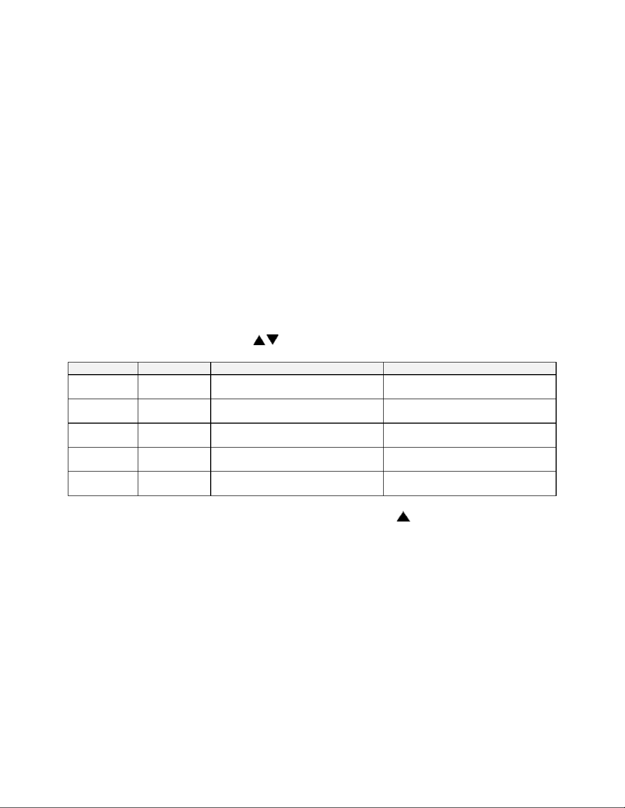
Digital Inputs (optional)
The Protocol Plus control can be run by external inputs wired to the control from an
external source such as a PLC or control panel switches. The external run operation
can Run, Hold or Stop profiles 1 through 7 (profile 8 can not be operated externally).
Refer to the table below for the inputs required for the desired operation. NOTE: A
profile must be created in the program page before trying to run a profile number.
Input 1 Input 2 Input 3 Profile Selected
ON OFF OFF 1
OFF ON OFF 2
ON ON OFF 3
OFF OFF ON 4
ON OFF ON 5
OFF ON ON 6
ON ON ON 7
OFF OFF OFF none
To start the selected profile, set Input 1, 2, 3 or 4 to ON.
To hold a profile, set Input 4 to OFF.
To stop a profile, set all inputs to OFF.
Digital Inputs
29
Page 36

Error Messages and Alarms
The Alarm Status Hi-limit LED is flashing. This indicates a problem with the
thermocouple, or the Hi-limit setpoint has been exceeded. Once the problem has
corrected, press the Reset pushbutton.
The Alarm Status Soak LED is flashing. This indicates that the oven temperature has
not entered or dropped out of the soak band and the soak timer has stopped.
The top LED Display reads OPEN. This indicates that either the Control or the Hi-limit
thermocouple is disconnected or broken. The lower LCD display should indicate which
thermocouple is the problem. Repair or replace the thermocouple.
The lower LCD display reads CONTROL SENS ERR. This indicates that the Control
thermocouple is disconnected or broken. The upper LED display should indicate OPEN
showing a thermocouple problem. Repair or replace the thermocouple.
The lower LCD display reads HI-LIM SENS ERR. This indicates that the Hi-limit
thermocouple is disconnected or broken. Repair or replace the thermocouple.
The lower LCD display reads HIGH LIMIT ALARM. This indicates that the Hi-limit
temperature setpoint has been exceeded. Determine if the setting is set too close to the
setpoint, the SSR is defective, or the calibration is incorrect.
30
Page 37

Quick Reference and Default Values
Program Page
Menu Item Display Default Range Setting
Ramp Time Seg 1 Pro-1 Seg-1 Ramp Time 00:00 00m00s to
99h59s
Event 1 Set Value Pro-1 Seg-1 Ramp Event 1 Off Off, On
Event 2 Set Value Pro-1 Seg-1 Ramp Event 2 Off Off, On
Event 3 Set Value Pro-1 Seg-1 Ramp Event 3 Off Off, On
Event 4 Set Value Pro-1 Seg-1 Ramp Event 4 Off Off, On
Soak Temp Seg 1 Pro-1 Seg 1 Soak Temp 68°F SPLowerLim to
SPUpperLim *
Soak Time Seg 1 Pro-1 Seg 1 Soak Time 00:00 00m00s to
99h59s
Event 1 Set Value Pro-1 Seg-1 Soak Event 1 Off Off, On
Event 2 Set Value Pro-1 Seg-1 Soak Event 2 Off Off, On
Event 3 Set Value Pro-1 Seg-1 Soak Event 3 Off Off, On
Event 4 Set Value Pro-1 Seg-1 Soak Event 4 Off Off, On
(repeat for segments 2-8)
High Limit Setpoint Pro-1 Hi-Lim SP Max
HiLimSP
Loop From Pro-1 Loop From XX No No, Seg-1 to
Loop To Pro-1 Loop To XX No No, Seg-1 to
Loop Count Pro-1 Loop Number 0 0 to 99
Profile Link Pro-1 Link To XX Stop Stop, Hold,
Guaranteed Soak Pro-1 Guar Band Off Off, 1 to 760°C
(repeat for profiles 2-8)
MinHiLimSP to
MaxHiLimSP *,
Band **
Seg-8
Seg-8
Pro-1 to Pro-8
(1400°F)
* See Enable Page
** Band value is set on Control Page
31
Page 38

Programming Table
Profile Number__________
Profile Name__________
Segment
Time
Ramp Soak
Events Events
1 2 3 4
Temp-
erature
Time
1 2 3 4
1
2
3
4
5
6
7
8
High Limit Setpoint
Loop From Seq
Loop To Seq
Loop Number
Link To Pro
Guar Soak Band
32
Page 39

Autostart
Menu Item Display Default Range Setting
Enable Autostart Auto Start Enable No No, Yes
Sunday mode Auto Start Sun Mode Off Off, Manual, Timer, Pro-1 to Pro-8
Sunday time Auto Start Sun Time 00:00 00:00 to 23:59
Monday mode Auto Start Mon Mode Off Off, Manual, Timer, Pro-1 to Pro-8
Monday time Auto Start Mon Time 00:00 00:00 to 23:59
Tuesday mode Auto Start Tue Mode Off Off, Manual, Timer, Pro-1 to Pro-8
Tuesday time Auto Start Tue Time 00:00 00:00 to 23:59
Wednesday mode Auto Start Wed Mode Off Off, Manual, Timer, Pro-1 to Pro-8
Wednesday time Auto Start Wed Time 00:00 00:00 to 23:59
Thursday mode Auto Start Thu Mode Off Off, Manual, Timer, Pro-1 to Pro-8
Thursday time Auto Start Thu Time 00:00 00:00 to 23:59
Friday mode Auto Start Fri Mode Off Off, Manual, Timer, Pro-1 to Pro-8
Friday time Auto Start Fri Time 00:00 00:00 to 23:59
Saturday mode Auto Start Sat Mode Off Off, Manual, Timer, Pro-1 to Pro-8
Saturday time Auto Start Sat Time 00:00 00:00 to 23:59
PID
Menu Item Display Default Range Setting
Display units PID Temp Unit °C °C or °F
Proportional band PID PB(H) 6°C 1 to 56°C (1 to 100°F)
Integral reset PID I(H) Rep/min 2 0 to 100 seconds/repeat
Derivative Rate PID D(H) in sec 0 0 to 500 seconds
AutoTune PID AutoTune Disable Disable, Enable
Proportional Band PID PB(C) 6°C 1 to 56°C (1 to 100°F)
Integral reset PID I(C) Rep/min 2 0 to 100 seconds/repeat
Derivative Rate PID D(C) in sec 0 0 to 500 seconds
Heat Offset PID Heat Offset 0°C
Cool Offset PID Cool Offset 0°C
-6 to 6°C (-11 to 11°F)
-6 to 6°C (-11 to 11°F)
33
Page 40

Control
Menu Item Display Default Range Setting
Cycle Time Control Cycle Time 1 1 to 60 seconds
High limit setpoint Control Hi-Lim SP Max HiLimSP MinHiLimSP - MaxHiLimSP*
High limit band Control Hi-Lim Band Off Off, 3°C to 11°C (5°F to 20°F)
Power fail recovery Control PwrFRec Stop Stop, Restart, Hold, Resume
Recovery time limit Control PwrFTime 00m00s 00m00s to 99m59s
Powerup start enable Control EPwrStrt Dis Dis, En
Powerup Start Mode Control StrtMode Off Off, Manual, Timer, Pro-1 to Pro-8
Hysteresis Control Hyst 3°C 1°C to 56°C (1°F to 100°F)
Process out low Control RetOutLo 80°C -73°C to 760°C (-100°F to 1400°F)
Process out high Control RetOutHi 400°C -73°C to 760°C (-100°F to 1400°F)
Time scale Control TimeScale hh:mm hh:mm or mm:ss
Key press beep Control KeyBeep On On or Off
End of cycle beep Control EOCBeep Off On or Off
Alarm beep Control AlarmBeep Off On or Off
Control Type Control Ctrl Heat/Cool Heat, Cool, Heat/Cool
*see Enable Page
Communication (optional)
Menu Item Display Default Range Setting
Address Communication CommAddr 1 1 to 255
Mode Communication CommMode OFF OFF, Modbus
Baud rate Communication Baud Rate 19.2K 2400, 4800, 9600,
19.2K, 38.4K
Parity Communication Parity None None, Odd, Even
34
Page 41

Real Time Clock
Menu Item Display Default Range Setting
Day of the week Clock Day Mon Sun, Mon, Tue,
Wed, Thu, Fri, Sat
Time of day Clock HH:MM 00:00 00:00 to 23:59
Reset clock Clock UP to Reset CLK* Ready Ready, Done
* if the key is not pressed, the clock values will retain their original values, the display
will change to Done if the clock is reset
Relay Outputs (optional)
Push Select key to select relay. If Relay 0 appears, no relays are installed
Menu Item Display Default Range
Type of relay Relay 1 RelayType Off Off, Alarm, Cycl, Ev1 to Ev4
Action of relay Relay 1 RelayAction NDE NDE, NE, NDEL, NEL*****
Type of alarm* Relay 1 AlarmType High High, Low, Plus, Minus, Band
Alarm setpoint* Relay 1 AlmHi/Lo SP 538°C -73°C to 760°C (-100°F to 1400°F)
Alarm deviation* Relay 1 AlmDevBand 3°C 1 to 56°C (1 to 100°F)
Inhibit alarm* Relay 1 ALMInhibit On En or Dis
Type of event** Relay 1 EventType Time Time or Temp
Event setpoint *** Relay 1 Event SP SPUpLim SPLoLim to SPUpLim****
(repeat for relay outputs 2-4, if available)
* appears only for alarm types
** appears only for time or temperature event types
*** appears only for temperature event types
**** see enable page
***** Normally de-energized and non-latching, normally energized and non-latching, normally de-energized and
latching, normally energized and latching
Table of Settings
Relay Type Action Alarm/
Event Type
Setpoint Alarm
Deviation
Alarm
Inhibit
35
Page 42

Test
Menu Item Display Default Range Setting
Heater output Test HeatOut Off On
High limit relay Test HiLimOut Off On
Relay 1 output Test Rly1 Out Off On
Relay 2 output Test Rly2 Out Off On
Relay 3 output Test Rly3 Out Off On
Relay 4 output Test Rly4 Out Off On
High Limit Sensor Test HL Temp (sensor reading)
Zone Cal
Menu Item Display Default Range Setting
Zone 1 actual Zone Cal Zone1Act 38°C -73°C to 760°C (-100°F to
1400°F)
Zone1 displayed Zone Cal Zone1Dis 38°C -73°C to 760°C (-100°F to
1400°F)
Zone 2 actual Zone Cal Zone2Act 260°C -73°C to 760°C (-100°F to
1400°F)
Zone2 displayed Zone Cal Zone2Dis 260°C -73°C to 760°C (-100°F to
1400°F)
Factory calibration* Zone Cal FactCal Ready Ready or Done (push- key)
*only use when no calibration instrument is available
Sensor Cal
Menu Item Display Default Range Setting
Control Sensor Cal Ctrl Sens 0F
Ctrl Sens 1000F
Ctrl Sens Done
HiLim Sensor Cal HL Sens 0F
HL Sens 1000F
HL Sens Done
Retransmit Cal RetCalLo XXXX *
RetCalHi XXXX *
* note that the actual RetCalLo and RetCalHi values displayed are of no importance.
** press keys until retransmission output = 1VDC
*** press keys until retransmission output = 5VDC
-100°F
1400°F
Done
-100°F
1400°F
Done
0
4096
-100 to 1400°F
-100 to 1400°F
(read only)
-100 to 1400°F
-100 to 1400°F
(read only)
0 to 4096**
0 to 4096***
36
Page 43

Enable Page
Menu Item Display Default Range Setting
Profiles Enable Profile 1-8 Yes Yes or No
Autostart Enable Auto Start No Yes or No
PID Enable PID Yes Yes or No
Control Enable Control No Yes or No
Communication Enable Communication No Yes or No
Real Time Clock Enable Clock No Yes or No
Relay outputs Enable Relay 1-4 No Yes or No
Test Enable Test No Yes or No
Zone Calibration Enable Zone Cal No Yes or No
Sensor Calibration Enable Sensor Cal No Yes or No
Setpoint lower limit Enable SPLowerLim 20°C -73°C to 760°C (-100°F to
1400°F)
Setpoint upper limit Enable SPUpperLim 260°C -73°C to 760°C (-100°F to
1400°F)
High limit overhead Enable HiLimOH 5°C 3 to 11°C (5 to 20°F)*
Password level 1 Enable Password 1 1 0 to 1000
Password level 2 Enable Password 2 2 0 to 1000
Manual/Timer mode
setpoint change
Analog Output Type Enable Analog Type Ctrl Ctrl
Enable SPChange Yes Yes or No
* Maximum high limit setpoint (MaxHiLimSP) = SPUpperLim + HiLimOH
Minimum high limit setpoint (MinHiLimSP) = SPLowerLim + HiLimOH
37
Page 44

Technical Specifications
UL, cUL listed: UL file E136675
CE compliance to:
Power supply:
Temperature:
Humidity: 90% or less, non-condensing
Sensor inputs:
Temperature
display:
Message display:
Time base: +/- 4 seconds accuracy in 24 hours
• EMC Directive 89-366/EEC
• European Standard EN55011/1991
• European Standard EN50082-2/1995
• 100 to 240 VAC +10% -15%, 50-60Hz, 30VA Maximum
• 12 to 24 VAC/VDC +/-10%, DC to 60Hz, 30VA Maximum
• Storage -20 to 60°C
• Operating 0 to 50°C
• Type J thermocouple -73°C to 760°C (-100°F to 1400°F)
• Input impedance 1M ohm or greater
• Common mode noise rejection of 140db@60Hz
• Common mode input voltage of +/-12.0VDC
• Sample rate of at least 1 sample per second
• Stability of +/- 0.5EC per 5EC change in ambient temperature
• Repeatability of +/- 0.5EC, or +/-0.1% of sensed temperature (whichever is
greater)
• Accuracy (@ 77°F +/-0.2 percent of span (+/-3°F)
• Supply Voltage Influence of +/-0.5EC per 10% change in nominal line voltage
• 1 degree resolution (C or F)
• Accuracy after calibration of +/- 1EC, or +/-0.2% of sensed temperature
(whichever is greater) @25EC
• Four-digit seven-segment LCD, 0.43 inches high (11mm)
• Readout Stability (+/-1°F/10°F Change in ambient temperature)
• Two-line, 16 alpha-numeric 5x7 dot matrix characters per line
• 0.2 inches high (5mm)
Heat control output: SSR Drive 24VDC nominal @ 70mA
Cooling control output: 4-20ma DC > 0-800 Ohm Load
Relay output: (plug-in
module)
Communications:
(plug-in module)
Remote inputs:
(plug-in module)
Front panel: NEMA 4X (with gasket)
Dimensions: 3.57H x 7.24W x 2.84D inches (91H x 184W x 72D mm)
Panel opening: 3.63H x 7.30W inches (92H x 185W mm)
Form A dry contact, rated 3 amps @ 24-264VAC
• RS232 Single drop, isolated
• RS422 Multi-drop, isolated
• RS485 Multi-drop, isolated
Dry-contact closure type with less than 250 ohm ON resistance
38
Page 45

APPENDIX: Temperature Scale
Conversion and Optional MRC5000
Setup
Temperature Scale Conversion (C/F)
The Protocol Plus controller can be operated in either C or F. The default setting for the
controller is C. Changing from one to the other is as follows:
1. Go into the Setup Mode on the controller.
2. Press the Select Key until Setup is displayed.
3. Press the Page key and Security will be displayed.
4. Press the Menu Key and Password will be displayed. Use the arrow keys to
enter the proper password. The default password is 2 for level two.
5. Once the proper password is displayed, press the Page key until PID is
displayed.
6. Press the Menu key and Temp Unit along with C or F will be displayed. Use the
arrow keys to change the setting.
7. Once the proper setting is displayed, press and hold the Page key for
approximately three seconds to exit the Setup Mode.
39
 Loading...