

Page 1
E-100
P. N. 208711
REVISION G
8/2006
DESPATCH PROTOCOL MANAGER
NETWORK UTILITY SOFTWARE
INSTALLATION AND OPERATION MANUAL
Prepared by:
Despatch Industries
8860 207th St. West
Lakeville, MN 55044
Customer Service 800-473-7373
Page 2

Thank you for choosing Despatch Industries. We appreciate
the opportunity to work with you and to meet your heat
processing needs. We believe that you have selected the
finest equipment available in the heat processing industry.
At Despatch, our service does not end after the purchase
and delivery of our equipment. For this reason we have
created the Service Products Group within Despatch. The
Service Products Group features our Response Center for
customer service. The Response Center will direct and track
your service call to ensure satisfaction.
Whenever you need service or replacement parts, contact
the Response Center at 1-800-473-7373: FAX 952-469-
8193.
Sincerely,
Despatch Industries
Page 3

TABLE OF CONTENTS
INTRODUCTION.............................................................................................................1
INSTALLATION...............................................................................................................2
Host Computer Requirements..............................................................................2
Installing the Software ..........................................................................................2
Software Setup.....................................................................................................6
Configuring the Controllers........................................................................6
Startup and Login ......................................................................................7
Setup ......................................................................................................... 9
Network Setup .........................................................................................12
Configuring a Recipe ...............................................................................21
Recipe Selection Setup ........................................................................... 27
Datalog Functions....................................................................................28
STARTING THE CONTROLLER ..................................................................................33
Run Time Window..............................................................................................34
Manual Mode...........................................................................................34
Timer Mode..............................................................................................35
Profile Mode.............................................................................................36
COMMUNICATION CARD INSTALLATION AND JUMPER SETTINGS ......................38
Wiring Diagrams.................................................................................................38
Communication Card Installation........................................................................39
Communication Card Jumper Settings...............................................................41
Connecting Protocol Plus Controller(s) to a Communications Host PC .............42
Single Oven.............................................................................................42
Multiple Ovens.........................................................................................42
TROUBLESHOOTING THE COMMUNICATIONS OPTION.........................................46
Controller Parameters..............................................................................46
Protocol Manager Parameters.................................................................46
Controller Hardware and Cabling.............................................................48
i
Page 4

INTRODUCTION
The Despatch Protocol Manager network utility software enables the operation of
multiple Protocol Plus controllers from a remote PC. As many as 32 Protocol Plus units
may be operated.
The software performs the following functions:
• Remote access and operation of one or more Protocol Plus controllers
• Allows use of a centralized PC to store and edit profiles
• Allows the same profiles to be downloaded to multiple controllers
• Allows a profile to be uploaded from a particular controller to the central PC,
so it can be passed to the other controllers
• Allows centralized data logging from all controllers connected to the central
PC
NOTE: Use this document in conjunction with Despatch publication E98 (p.n.
143895), Protocol Plus Control Instruction Manual.
1
Page 5
INSTALLATION
Host Computer Requirements
The host computer must be Pentium-class or equivalent, running Windows 95,
Windows 98, Windows NT, Windows 2000 or Windows XP.
An RS-232 serial port, COM1 – COM4, must be available.
Installing the Software
NOTE: Close all open applications before installing Protocol Manager software.
1. Insert the Protocol Manager software CD-ROM into the CD drive of the
control computer.
2. Click on the start button in the lower left corner of the screen.
3. Click on the "Run" button from the menu that appears.
4. Click on the Browse button. Change the Look In box at the top of the window
to the drive letter for your CD drive.
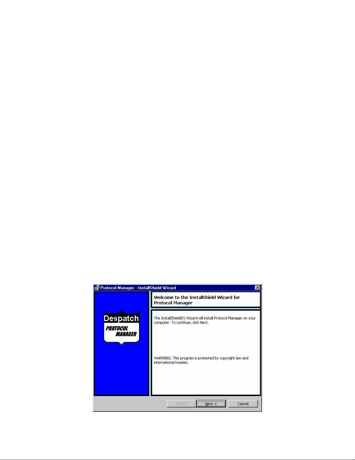
5. Double-click on the Setup.exe file. The following screen will appear:
Figure 1 Protocol Manager Installer
2
Page 6
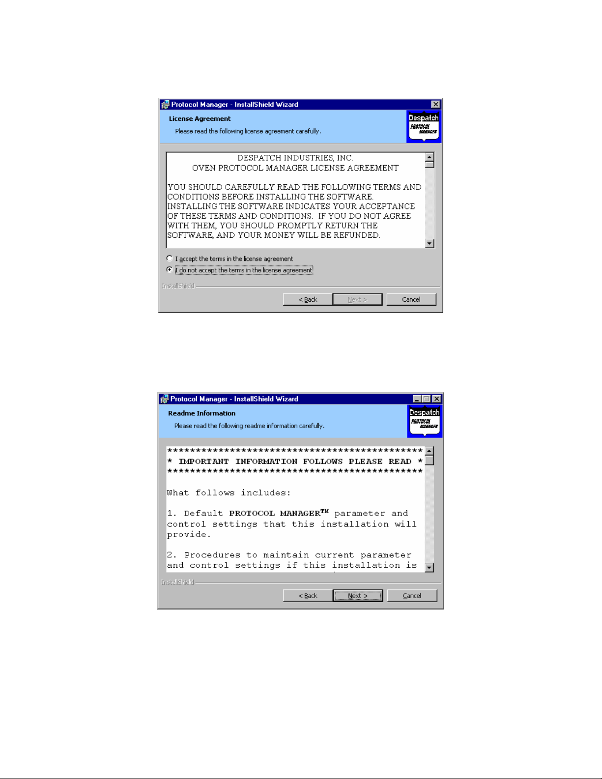
6. Click on the Next button. The following screen will appear:
Figure 2 License Agreement
7. Scroll the window to read the license agreement, then click on the "I accept
the terms" button and click Next to continue. The following screen will appear.
Figure 3 Initial Setup Parameters ReadMe
3
Page 7
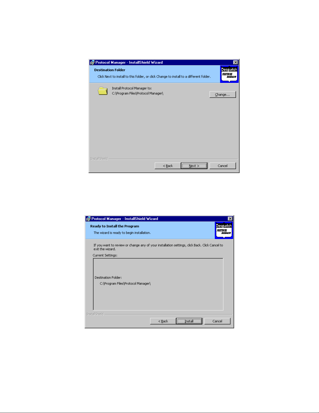
8. Scroll the window to read all the information, then click Next. The following
screen will appear.
Figure 4 Destination Folder Selection
9. Either accept the directory shown and click Next, or select a new directory
using the Change button, then click Next. The following screen will appear.
Figure 5 Install Screen
4
Page 8
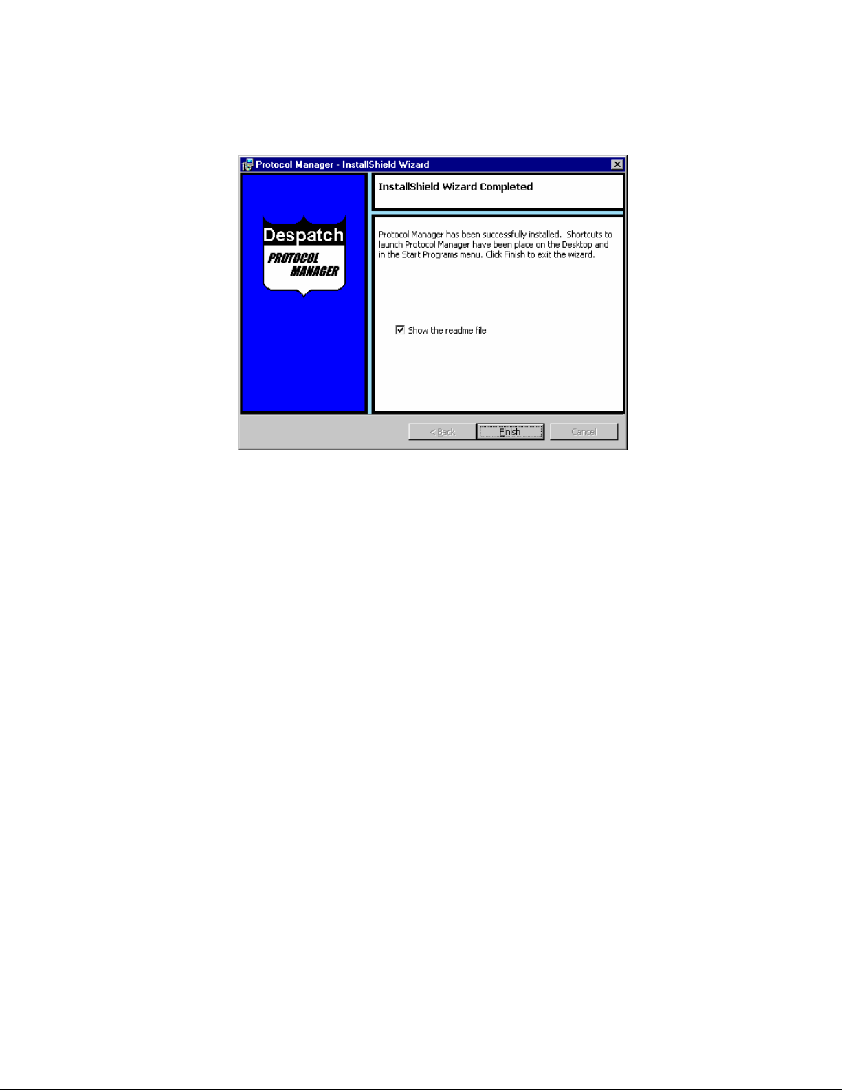
10. If all is in order, click the Install button to install the software. When the
installation is complete, the following screen will appear.
Figure 6 Completion Screen
11. If the “Show the readme file” box is checked, the ReadMe file displayed in
Figure 3 above will be opened for reading again, if necessary. Uncheck the
box to skip reading the file again. Click on Finish to complete the installation.
5
Page 9

Software Setup
Configuring the Controllers
1. Use the keys on the faceplate of each Protocol Plus controller to set these
parameters. Consult Despatch Manual E98 for information on this process.
2. On each of the controllers, the following parameters must be defined in order
for the new control software to communicate with the controllers. Normal
conditions use the settings listed in parentheses in the Communication
Page in the Setup Mode of the controller.
• Address (1 - 247) - A unique address must be assigned to each controller.
Make certain that controller addresses are known when setting up the
software.
• NOTE that each of the multiple controllers must have a different address.
• Communication mode (MUST be Modbus)
• Baud rate (19.2 K)
• Parity (none)
6
Page 10
Startup and Login
1. Start the application by clicking the Windows taskbar's Start button, then
clicking Programs from the menu that appears, then clicking the Protocol
Manager option from the list that appears.
a. NOTE: The very first time this is done, a prompt may appear that there is
no setup information yet, and that the password is despatch.
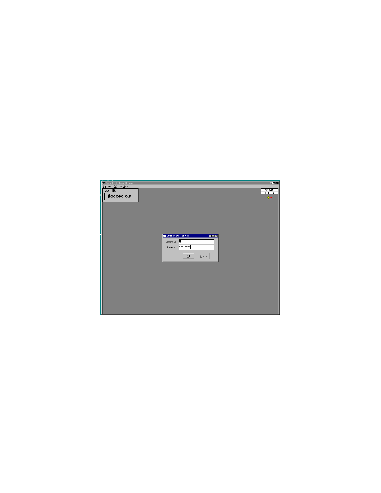
2. From the main screen that appears, select Login from the pulldown menu (or
double-click where it says (logged out) to log in. Note that an Operator ID
must be typed in, to log into the software. Type despatch into the Password
space. See Figure 7. NOTE that the Operator ID can be up to 16 characters
long.
Figure 7 ID and Password Entry
When login is successful, the User ID will appear in the upper left corner of the
screen. NOTE that different operator levels have different colors behind the User
ID: Level 2 is black, Level 3 is green, and Level 4 is red. See Figure 8.
7
Page 11

Figure 8 User ID After Login
8
Page 12
Setup
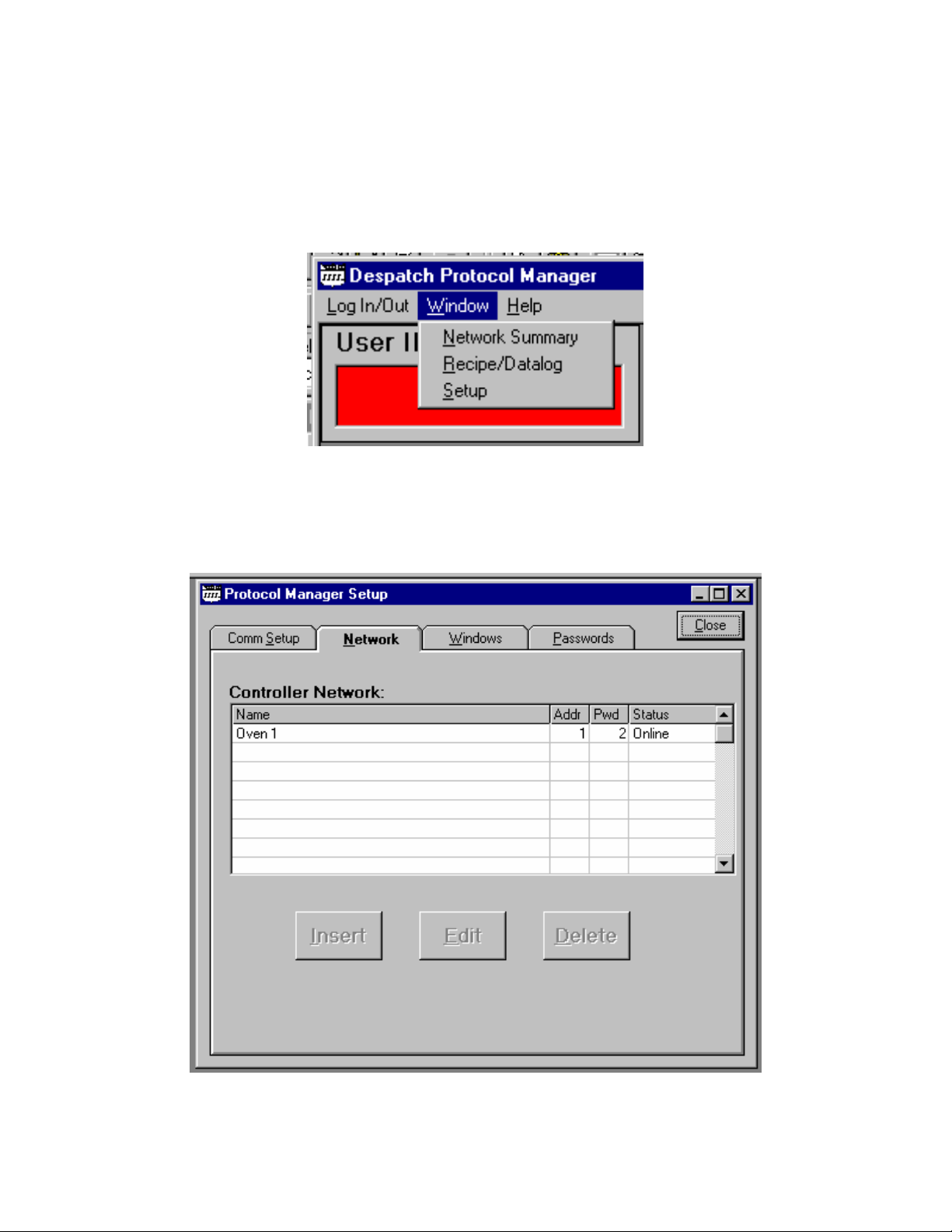
1. At this point the system must be set up. Move the cursor to the top of the
screen and click on the Window prompt to reach the Setup pulldown. See
Figure 9.
Figure 9 Setup Pulldown
2. Click on the Setup prompt, and the Software Setup window will pop up. See
Figure 10.
Figure 10 Software Setup Window
9
Page 13

Comm Setup
The first tab on the left is the Comm Setup tab. Use the cursor to make selections to
allow the computer and Protocol Plus controllers to communicate.
Figure 11 Protocol Manager Setup: Comm Setup Tab
1. Port Selection
• COM 1
• COM 2
• COM 3
• COM 4
Select the communication port that matches your host computer hardware.
2. Baud Rate
• 2400
• 4800
• 9600
• 19.2 K
• 38.4 K
10
Page 14

Select the baud rate that corresponds to the rate programmed into the Protocol Plus
controller(s). 38.4 K provides fastest communication. If the controller(s) will not go
on line, try a lower speed.
3. Parity Option
• None
• Odd
• Even
Select the parity that corresponds to that which is programmed into the Protocol
Plus controller(s).
4. Use Long Timeout Delay checkbox
The software uses a timer to check Protocol controller response time. The software
calculates acceptable response time - especially critical when using multiple
controllers. If an unexpected communication failure occurs, checking this box will
increase the communication timeout period. NOTE: For normal operation, leave this
box unchecked: don't check this box unless a communication failure occurs.
5. Press the Accept button to save the selected parameters. Press the Restore
button to return to the previously saved parameters.
NOTE that changes will not take effect until the Accept button is pressed.
6. Click on the OK button to save settings.
11
Page 15
Network Setup
1. The second tab from the left on the Software Setup window is the Network
tab. Select this tab to add controllers to the system. See Figure 12. Note that
if all the buttons are not active, click on the space below the Name to activate
the insert button.
Figure 12 Protocol Manager Setup: Network Tab
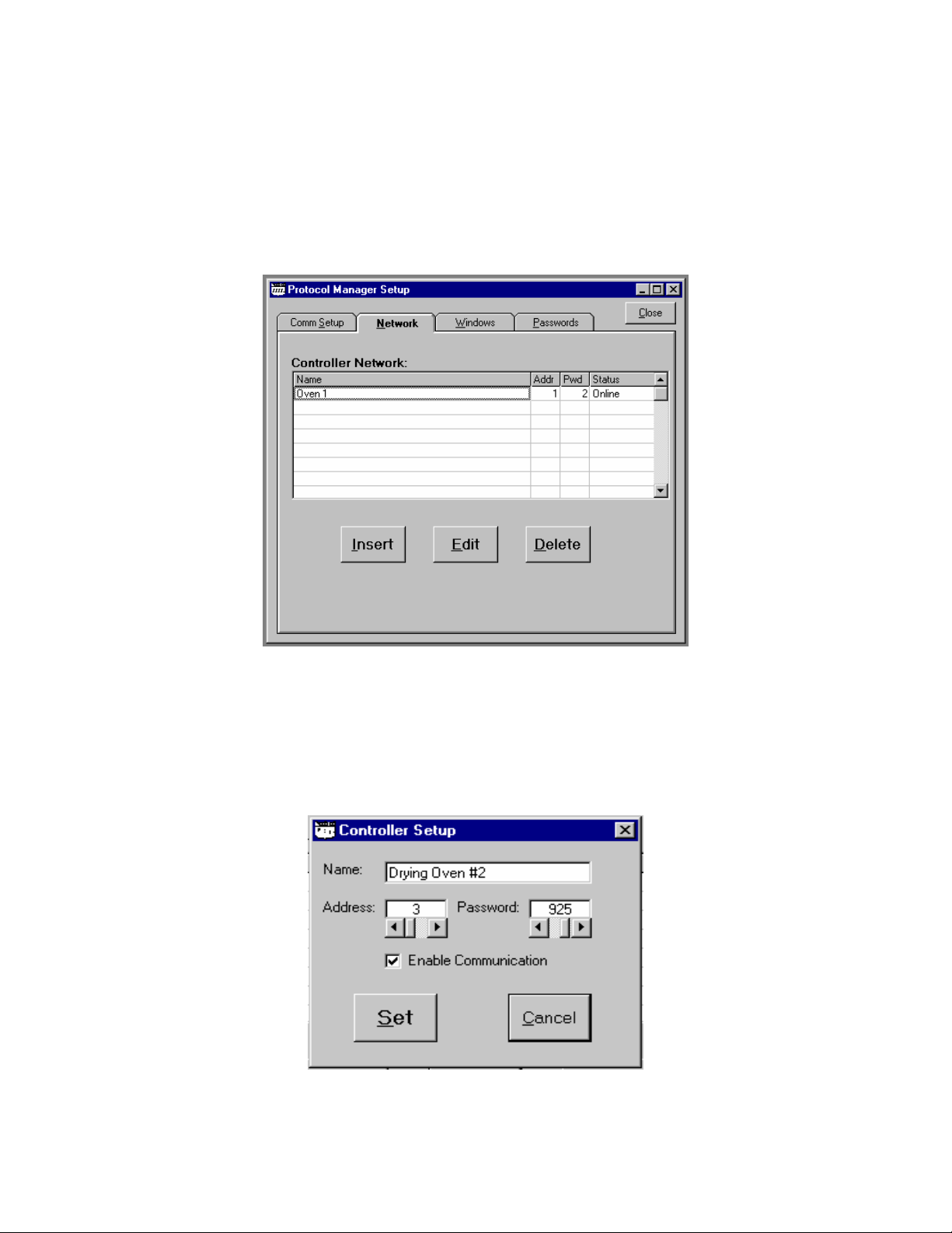
2. Use this screen to add as many controllers as are connected to the host PC.
Click on the first blank line to select it, then click the Insert button and press it
to add a new controller to the software. The Controller Setup window will
pop up. See Figure 13.
Figure 13 Controller Setup Window
12
Page 16

Name Field: Designate and type in the name of the oven or controller, up to 24
characters long, maximum.
Address Field: Type the address or move the slide bar of the Address field to
enter the address of the controller. (This field must correspond with the address
programmed into the controller on the Communication Page; see Manual E-98
for directions.) Values 1 through 247 are accepted.
Password Field: Type the password or move the slide bar of the Password
field to enter the password Level 2 of the controller. (This field must correspond
with the Level 2 password programmed into the controller on the Enable Page;
see Manual E-98 for directions.) Values from 1 to 1000 are accepted. Default is
2.
Enable Communication Checkbox: Use the cursor to check this box to add it
to the list of controllers working under the software. If the status for the controller
shows DISABLED in the Status column of the Network tab of the Software
Setup window (see Figure 12), this box must be rechecked.
A controller can be disabled by leaving this box unchecked. Communication will
not be attempted with disabled controllers, which may be desirable if an oven is
shut off (not used) for a long period of time.
3. When the chosen parameters have been entered, press the Set button on
the popup. A question box will pop up (see Figure 14).
Figure 14 Controller Question Popup
4. Click Yes to add the controller to the network.
13
Page 17

Windows Setup
1. The third tab from the left on the Software Setup window is the Windows
tab. This allows the operator to select the parameters that may be viewed
from the Network Summary Window and the Controller Run Time window.
Press this tab to bring up its screen. See Figure 15.
Figure 15 Protocol Manager Setup: Windows Tab
Use the checkboxes on the left side of the screen to select which parameters
to display when viewing the Network Summary Window and Controller
Run Time Window (both described below). Press the Accept button to save
the selected parameters . Press the Restore button to return to the
previously saved parameters.
On the right side of the screen, select the alarm sound from one of five preset
sounds for high limit trip, and for soak deviation from guaranteed soak band.
(If no sound card is detected, the Alarm Sounds field is grayed out.)
2. Click Yes to save settings.
14
Page 18

Software Setup: Passwords Setup
The fourth tab from the left on the Software Setup window is the Passwords tab.
Press this tab to bring up its screen. See Figure 16.
Three levels of passwords may be set at this screen, which controls the software login
level. The highest level, Level 4, enables the user to change communication settings,
add/delete controllers from the network, change passwords, and perform all lower-level
operations.
The next highest login level, Level 3, enables the user to edit/write recipes, configure
data log settings, and perform all lower-level operations.
The next login level, Level 2, enables the user to change controller modes, select
profiles, change set points, start data logging, and perform Level 1 operations.
The lowest login level, Level 1, allows the user to view run-time status, and start, stop
or hold controller operation. No password is required.
Figure 16 Protocol Manager Setup: Passwords Screen
15
Page 19

Values from 0 minutes to 60 minutes may be set in the Auto Logoff Time window,
which will automatically log the operator off the system after this predetermined period
of time. Setting this value to zero disables this feature and the system will not
automatically log off. Press the Accept button to save the selected parameters. Press
the Restore button to return to the previously saved parameters.
The 'Can Exit if Not Logged In' option can be checked to allow Protocol Manager to
be stopped at any time. If this option is left unchecked, Protocol Manager can only be
stopped if a user has successfully logged in at any level.
Exit the Setup Mode by clicking the X box at the upper right-hand corner of the
Software Setup box.
16
Page 20

Network Summary Window
Figure 17 Network Summary Window
To view the Network Summary Window, click on the Windows prompt to reach Network
Summary. Click on the Network Summary prompt, and the Network Summary Window
will pop up. See Figure 17.
The Network Summary Window simultaneously displays parameters for all the
controllers connected in the system. Parameters that may be displayed in the Network
Summary Window are:
Χ Controller Name and Address
Χ Temperature Setpoint and Value
Χ Alarms and Events Status
Χ Cycle Complete and Buzzer Status
Χ Operating Mode
Χ Run/Stop/Hold Status
Χ Controller Online/Offline Status
Use the check boxes in the Windows tab (Software Setup page) to select how many
of these parameters will be shown. Figure 17 shows the Network Summary Window
with all of the parameters available.
Double-click on a Controller ID in the Name column to display the associated
Controller Run Time Window (see Figure 18).
17
Page 21

Controller Run Time Window
Figure 18 Controller Run Time Window
The Controller Run Time Window displays current status of an individual controller.
Parameters that may be displayed in the Controller Run Time Window are:
Χ Controller Name and Address
Χ Temperature Setpoint and Value
Χ Alarms and Events Status
Χ Cycle Complete and Buzzer Status
Χ Operating Mode
Χ Run/Stop/Hold Status
Χ Controller Online/Offline Status
Χ High Limit Setpoint and Value
Χ Time Remaining in Timer Mode
Χ Profile, Segment, and Time in Profile Mode
Χ Operator ID
Χ Lot Information
Recipes are started, run, and stopped from this window. This window may be used to
remotely control the controller's operating mode and state. If this window disappears,
click on the Network Summary window and double click on the controller name. If the
Network Summary window does not appear in the main menu, click on windows on
the task bar and then click on Network Summary on the pulldown menu.
18
Page 22

The Controller Run Time Window initially appears “collapsed” as shown below:
Figure 19 Collapsed Controller Run Time Window
Double-Clicking the “Cycle COMPLETE” indicator will alternately expand or collapse the
Controller Run Time Window.
The expanded window appears as shown below if Lot Datalogs have not been enabled
(see “Datalog functions”):
Figure 20 Expanded Controller Run Time Window
19
Page 23

The expanded window appears as shown below if Lot Datalogs have been enabled
(see “Datalog functions”):
Figure 21 Expanded Controller Run Time Window with Lot Datalogs Enabled
20
Page 24

Configuring a Recipe
To create a recipe, go to the bar at the top of the screen and pull down to Recipe/
Datalog from the Window designation. The Recipe Editor Window will appear. See
Figures 22 and 23.
Figure 22 Recipe/Datalog Pulldown
Figure 23 Recipe Editor Screen
21
Page 25

Double-click on the fields in the center of the Recipe/Datalog window to bring up a
window box to access and change the value shown. Move the slider to change the
value quickly. Click on the arrow at either end to change the value by 1. Click in the
white space to the left and right of the slider to change the value by 10. Click OK to lock
in the change. See Figure 24.
Figure 24 Value Change Window
Parameters on the Recipe screen include:
Recipe Name
Type the name of the new recipe being created.
Seg#
Ramp Time
EV1 through 4
Soak Temp.
Recipe segments 1 through 8 may be programmed, each with its
own set of events, ramp and soak times, and soak temperature.
The time required to ramp setpoint up to temperature may be
programmed here. Values between 0 and 99:59 are allowable. As in
the Protocol Plus controller, profile ramp and soak times are stored
without units. Units are independently set locally, in the actual
controller, as either hours and minutes (HH:MM) or minutes and
seconds (MM:SS).
From 1 to 4 events may be programmed into the ramp time portion
of each segment here. These typically involve actuating/disabling
relays to close/open valves or perform other relay-controlled
functions. NOTE: These will only actuate when the controller has the
relay cards installed and programmed for an event. Recipes may
contain four Ramp and four Soak event choices, although only those
relays actually supplied in a Protocol Plus controller and configured
for events will be affected by recipe settings, when used to run a
profile.
The temperature of a particular segment is entered here; it can
range from -18 to 540 degrees C (0 to 1000 degrees F). See Notes
on Soak Temp and Hi Limit SP, below.
Soak Time
The duration of soak is entered here; the value can range from 0 to
99:59.
22
Page 26

EV1 through 4
From 1 to 4 events may be programmed into the soak portion of
each segment here. These typically involve actuating/disabling
relays to close/open valves or perform other relay-controlled
functions. NOTE: These will only actuate when the controller has the
relay cards installed and programmed for an event.
Guaranteed
Soak Band
Hi Limit SP
Loop from
Segment ___
to Segment
___ ___ times
Link to Profile
Temp. Units
If the process temperature deviates from the setpoint by more than
this value, the timer is placed in a hold condition. The timer
continues when the process temperature falls within range.
The high limit setpoint may be entered here; if the temperature
exceeds this value, the hi-limit will alarm and shut off the heater. See
Notes on Soak Temp and Hi Limit SP, below.
These values enable the profile or controller to jump from a certain
step to another step of the recipe a preset number of times.
Values for the end of profile option are:
STOP Stop oven operation
HOLD Hold setpoint
1 – 8 Jump to selected profile number
STBY Enter standby mode. See note on Standby Mode below.
Selects degrees Fahrenheit or Centigrade, for the recipe display
only. Recipes stored on the host PC, like profiles in the Protocol
Plus, are always stored with temperatures in degrees Fahrenheit,
regardless of the selected viewing units. Note that changing the
display units converts displayed recipe temperatures accordingly.
OPEN/SAVE
(to Folder)
READ/WRITE
(to Controller)
Profile
Number
These buttons enable the operator to open a new recipe, or save the
current one to a predetermined folder.
These buttons enable the operator to upload a recipe from one of
the Protocol Plus controllers in the system, or to write the current
recipe to one of the controllers.
Selects which of the Controller's eight profiles is used when reading
or writing recipes.
Notes on Soak Temp. and Hi Limit SP Values
In the recipe editor screen, Soak Temp and Hi Limit SP values can be adjusted in the
range of -18 to 538 °C (0 - 1000 °F). Errors may occur attempting to download a recipe
to a Controller's profile if one of the recipe's ramp times, soak temperatures, or the high
limit setpoint value is incompatible with the range set internally for the target controller.
In this case, an error message similar to Figure 25 will be displayed, and no changes
will be made to the Controller's profile.
23
Page 27

Figure 25 MODBUS Comm Error Message
Note on Standby Mode
In the recipe editor screen, the Link to Profile value “STBY” option (Standby mode)
can only be used with Protocol Plus controller version 4 or higher. If a recipe with the
Standby mode selected is chosen for download to an earlier version controller, a popup
message will be displayed by Protocol Manager, and the downloaded profile will set the
Link to Profile value to the “HOLD” option for that controller.
Figure 26 Standby mode Message
Creating a New Recipe
1. Pull down from the Windows/Recipe/Datalog position on the menu bar to
Recipe.
2. Press the NEW button.
24
Page 28

3. Enter the values desired.
4. Press SAVE to save the recipe.
Opening an Existing Recipe
1. Press the OPEN button at the bottom of the Recipe Editor screen.
2. Select the recipe from the popup list.
25
Page 29

Reading/Writing a Recipe to/from a Controller
1. Select the controller from the box at the bottom right corner of the Recipe
Editor screen. See Figure 27. Only controllers that are currently enabled and
Online will be listed in the box.
Figure 277 Read/Write Area, Recipe Editor Screen
2. Select a profile (1 through 8) to be read/written from/to the controller.
3. Press the READ or WRITE button to either call up the recipe from the
selected controller, or write the current recipe to the selected controller.
NOTE: Reading the parameters from a controller will overwrite any information stored in
the displayed recipe.
26
Page 30

Recipe Selection Setup
1. Go to the second tab from the left at the top of the Recipe Editor screen.
2. Click on this tab and the Recipe Selection screen will pop up. See Figure 28.
Figure 288 Recipe Selection Screen
The Selectable Recipe Files list indicates which recipes can be selected by name
when starting a profile run remotely. Recipes can be added to this list by clicking the
"Add" button and selecting a recipe from the list box that pops up.
Profiles can be started remotely by profile number only if the "Start Profile by Number"
option is chosen as shown above. If the "Start Profile by Recipe Name" option is
chosen in this window, starting a profile will require selection of a recipe, by name, from
the "Selectable Recipe Files" list that will be displayed in the controller start window
(see "Starting the Controller").
27
Page 31

Datalog Functions
Datalog files are maintained to periodically record controller data to a disk file for future
analysis. Protocol Manager can maintain two different types of datalog files from
networked controllers.
Profile Datalogs – are initiated automatically when a controller is remotely started
running, and are closed automatically when the controller stops running. Profile
datalogs are useful for jobs that are based on a specific process run.
Log Datalogs – are initiated, and subsequently closed, manually, using the Controller
Run Time Window, regardless of the controller's running status. Log Datalogs are
useful for jobs that are not related strictly to an entire, single process run.
Both types of datalog files will contain header information, followed by periodic data
records. Header information and record data are set for both types of datalogs in the
Profile Datalog Window. Both types of files will be stored in the Log File Folder path
indicated in the Profile Datalog window.
The Profile Datalog window also allows setting file naming options and log entry interval
options for Profile Datalogs.
The Lot Datalog window is used to enable Lot Datalogs, and set the Log Entry interval
specifically for Lot Datalogs.
28
Page 32

The Profile Datalog and Lot Datalog screens are accessed from the tabs at the right
side of the initial Recipe Editor screen, off the Recipe/Datalog Window. See Figures
29 and 30.
Figure 299 Profile Datalog Window
Select the parameters to be written to the datalog by checking the boxes on the Profile
Datalog Window screen.
Log File Header Information
Check the following boxes to select the types of data to be written into the log file
header:
Χ Controller Name
Χ Start Date and Time
Χ Operator ID
Χ Lot Information
29
Page 33

Log File Record Data
Check the following boxes to select the types of data to be written into the log file itself:
Χ Elapsed Time
Χ Entry Date and Time
Χ Temperature Setpoint
Χ Temperature Value
Χ Alarms and Events Status
Χ Recipe Name
Log File Folder
This field displays the folder used to store datalog files.
Log At Intervals/Log at Profile Change
These buttons determine whether data will be logged at a certain time interval (see Log
Entry Interval, below), or if data will be logged at every change point programmed into
the recipe (start point, beginning of ramp, beginning of soak, etc.). Select one of these
logging options depending on the detail level required, and the amount of disk space
available for log records. Typically, a short run with few steps might use the time interval
option, and a long run with many steps might use the profile change option.
Log Entry Interval: This value controls how often data is logged into a local disk file
when selected for a running controller. For example, if two minutes is selected, data will
be logged from each running controller approximately every two minutes; it does not
mean that all controllers will be polled for data within a two minute period.
The minimum usable interval depends on the number of controllers in the network.
Typically, the minimum interval, in seconds, can be approximated by Tmin = 4 + N,
where N = number of Controllers on the network.
Datalog files take up storage space. Typically, a log file's header contains from 10 to up
to about 250 bytes, plus Lot Information (Lot Information contains from 0 to 576
bytes), depending on which header information is selected. Each logged data entry
contains up to 50 bytes, depending on which data is selected. One running controller,
logging data every 15 seconds, would produce a datalog growing at a rate of about 11
Kbytes per hour. 11 Controllers running at this rate would consume about 1 Mbyte of
storage every 8 hours.
The datalog is enabled by the Enable Datalog checkbox in the Run Time Window
(described later in this manual).
30
Page 34

Log File Naming Options
Log file names consist of a Controller ID and Time Stamp, created when a data log is
started.
Controller ID
Identifies the controller by address (three digits with leading zeroes) or name. If name is
selected, blank spaces and characters not legal for use in a Windows file name are
converted to underscore characters.
Time Stamp
Select the time format used for the log entries.
Notes on Log File Naming Options
The Controller ID and Time Stamp are combined, but separated by an underscore
character, to create a datalog file name prefix. The file name is automatically appended
with a ".log" extension.
For a controller named "East Fab #1" with an address of 2, a datalog file name would
either begin with "002" (if Address selected) or "East_Fab_#1" (if Name selected).
For a run started on February 4th, 2000, at 2:13:45 pm, the Time Stamp would be
either "000204" (if YYMMDD selected), "00020414" (if YYMMDDhh selected),
"0002041413" (if YYMMDDhhmm selected), or "000204141345" (if YYMMDDhhmmss
selected).
If "Name" and "YYMMDDhh" were selected, the complete file name prefix would be
"East_Fab_#1_00020414", and the new datalog filename would be
"East_Fab_#1_00020414.log". If a file with that name already existed, however, the
new file would be renamed "East_Fab_#1_00020414_1.log".
When a datalog is started, and a filename is created, duplicate filenames are checked
for; if a file with the created name already exists, the new filename's prefix has an
underscore and a numerical value appended to it to create a unique filename.
31
Page 35

Figure 30 Lot Datalog Window
The Lot Datalog screen enables datalog functions to be selected on a per-job basis
rather than for all jobs.
32
Page 36

STARTING THE CONTROLLER
The controller is started by using the Controller Run Time Window(s) which are
accessed from the Window pulldown off the main screen.
Start the profile by pressing the RUN/HOLD button at the top right portion of the
Controller Run Time window. The Start Running screen will appear. See Figure 31.
Figure 301 Controller Run Time Window
NOTE that the operator need not be logged in to start or run the controller from the Run
Time Window. However, the Start Running screen requires a login.
33
Page 37

Run Time Window
Three different modes of operation are available as tabs from the Start Running
screen:
Χ Manual mode
Χ Timer mode
Χ Profile Mode
Manual Mode
Figure 32 illustrates the Manual operating mode. The process run is held at a single
setpoint temperature until the STOP button is pressed at the Controller Run Time
Window. Process setpoint, hi-limit setpoint and event status may be entered in the
appropriate fields.
Figure 312 Start Running Screen: Manual Mode
34
Page 38

Timer Mode
Figure 33 illustrates Timer Mode. This mode allows the operator to start and stop the
process for a preset length of time.
Figure 33 Start Running Screen: Timer Mode
The timer mode is similar to the manual mode except that the time at temperature is
added.
If the soak band temperature deviates from this setting, the timer is placed in a hold
condition.
35
Page 39

Profile Mode
Figure 34 illustrates Profile Startup Mode with the "Start Profile by Number" option
selected (see "Recipe Selection Setup"). In this mode, one of eight separate profiles
(recipes) may be run. Profiles are created or added to the system at the Recipe Editor
Screen (Figure 23). NOTE that if a profile number is selected here, but was not created
and stored, the profile will not start.
Figure 324 Start Running Screen: Profile Mode
36
Page 40

Figure 35 illustrates Profile Mode startup with the “Start Profile by Recipe Name” option
selected (see “Recipe Selection Setup").
Figure 335 Profile Mode Startup with "Start Profile by Recipe Name"
NOTE: The list of recipes shown is created from the collection of recipes that have
been stored locally. Selecting to start a profile using a recipe from this list will first cause
the recipe to be downloaded to the controller as Profile 8, then Profile 8 will be started.
37
Page 41

COMMUNICATION CARD INSTALLATION
AND JUMPER SETTINGS
Wiring Diagrams
Figure 346 RS232 Wiring
Figure 357 RS422A Wiring (4 wire)
Figure 368 RS485 Wiring (2 wire)
38
Page 42

WARNING
Electronic components are extremely sensitive to static electricity. Before opening
the controller case, read and follow the precautions below to prevent damage from
static electricity.
1. Turn off power to the controller.
2. Touch a bare metal surface on the exterior of the controller.
3. Disconnect the power connection from the controller or unplug from the
power source.
Also follow these static electricity precautions:
• Avoid static-causing surfaces while working with electronic components.
• Remove parts from their anti-static bags only when ready for use. Do not lay parts
on the outside of the anti-static bag because only the inside provides protection.
• Hold circuit boards by their edges or any metal mounting hardware. Avoid touching
components or connectors on the circuit boards.
Communication Card Installation
1. Turn off power to the controller.
2. Remove the back cover of the controller by removing the two screws at the
top of the unit.
3. Looking into the back of the controller with the connector terminal strips at the
bottom, install the communication card onto the two 5 pin headers on the rear
circuit board. Be sure the jumper blocks on the communication card are
positioned toward the bottom of the controller. See Figure 39, Controller Rear
View with Communication Card (left). Be sure the card is seated firmly onto
the headers.
4. Set the jumpers on the communication card for the desired serial
communication interface based on Figure 40, Communication Card Jumper
Settings.
5. Reinstall the back cover.
6. Wire the communication connections on the rear of the unit for the desired
serial communication interface based on Figure 36, RS232 Wiring, Figure 37
RS422A Wiring (4 wire), or Figure 38, RS485 Wiring (2 wire).
7. Reapply all power connections to the controller.
39
Page 43

Figure 39 Controller Rear View with Communication Card (left)
40
Page 44

Communication Card Jumper Settings
1. Turn off power to the controller.
2. Remove the back cover of the controller (if it is not already removed) by
removing the two screws at the top of the unit.
3. Set the jumpers on the communication card for the desired serial
communication interface based on Figure 40, Communication Card Jumper
Settings, below.
4. Reinstall the back cover.
5. Reapply power to the controller.
Figure 40 Communication Card Jumper Settings
41
Page 45

Connecting Protocol Plus Controller(s)
to a Communications Host PC
Single Oven
If the oven purchased was not supplied with communication option, order Despatch RS232 communication kit P/N 161968. This kit contains all the parts required for one oven
to host PC via RS-232 including: Protocol Plus add-on communications board, oven
internal cabling, 25 foot null modem cable and Modbus protocol instruction manual.
For single oven communication, the Protocol Plus controller should be configured for
RS-232 connection. Connect the host PC’s RS-232 COM port to the oven’s
communication port using a null-modem cable. Despatch P/N 161971 provides a 25
foot null-modem cable. Refer to Protocol Plus Manual for communication card jumper
and controller configuration settings.
Multiple Ovens
If the ovens purchased were not supplied with communication option, order Despatch
P/Ns 141820, add on Protocol Plus communication board, and 161950 (the internal
cabling) to make the ovens communication-ready including DB9 external cable
connections. Order Despatch P/N 161955 for the components required to network two
ovens to a host PC. This kit includes RS-232 to RS-422/RS-485 bi-directional adapter,
cabling, and Protocol-specific termination plugs.
Generically speaking, the following description details the steps necessary to network
multiple Protocol Plus controllers:
The host PC must have its assigned RS-232 COM port connected to a RS-422/RS-485
bi-directional adapter, for example a “B&B Electronics” adapter Despatch P/N 161938-
40. These P/Ns provide the adapter, power supply and PC-to-adapter serial cable.
The following wiring description refers specifically to the B&B device, but may be
applied to acceptable substitute devices.
The Protocol Plus controller’s optional communication card should be configured for
RS-422A 4-wire connection. Set the dipswitches and jumpers on the adapter to match
the communication from the host PC RS-232 COM port to the adapter. Wiring from the
B&B adapter’s RS-422A RS-485 terminals is daisy-chained to each of the Protocol Plus
controllers. Connect the power supply pigtail leads from the adapter wall mount
transformer into the +12V and GND on the adapter. Plug the transformer into a
standard 120V / 60 Hz supply outlet.
It is important to note that the communication ready ovens are supplied with two DB9
42
Page 46

network ports; “Communication In” and “Communication Out”. For shorter networking
runs, standard serial communication rated cables are available in a variety of lengths.
For example; Despatch P/N 161970 is a 25 foot serial cable. DB9 termination plugs are
also available from Despatch including P/N 161969; the required termination for a RS422 4-wire network. See remaining information if longer network cable lengths are
required.
Typically, RS-422A/RS-485A cables consist of three individually shielded twisted pairs;
one pair transmits data from the Host PC to the ovens, one pair transmits data from the
ovens to the host PC, and one conductor from the third pair is the signal common. The
remaining conductor of the third pair is unused. Cable such as Belden type 9843 should
be used.
The network requires a cable breakout junction box near each oven. 120 ohm
terminating resistors must be installed at each end of the RS-422/RS-485 network.
Refer to the following page for a simplified network wiring diagram. In this case, "To
Host PC" actually indicates a cable connection to the B&B adapter. The "PC Rcv" and
"PC Xmit" terminals refer to the B&B adapter's RD and TD terminals respectively.
Install the 120 ohm resistor between the RD+ and RD- terminals. Connect the GND
wire to the 422/485 GND terminal. The remaining termination resistor is applied at the
RD+ and RD- terminals of the “last in line” networked oven.
RS-422/RS-485 allows communication over wires up to 1000 meters in length. It is
important to note that the associated runs from the oven’s Protocol Plus controller to
the breakout junction box be limited to 5 meters maximum. The junction boxes provide
a drop from the network cable to each oven. The cables marked “to Oven Controller”
are terminated with 9-pin male subminiature “D” plug for mating with the oven
controller’s Communication In” serial data receptacle.
Wire drop the cable according to the following table:
Oven signal Junction box terminal 9-pin plug pin number
Rcv+
Rcv-
Xmit+
Xmit-
GND
5 2
4 7
1 3
2 4
3 5
The daisy chain drop cables may use shielded pairs. Cable shields should be
connected as follows:
• At each junction box - to the box interior chassis.
• At each drop cable 9-in plug-to the lug shell if conductive.
If a non-conductive shell is used, no connection is required.
43
Page 47

Figure
37
. Junction Box Wiring
44
Page 48

The junction boxes are used to provide a drop from the network cable to each Oven.
The cables marked "To Oven Controller" are each terminated with a 9-pin Male
subminiature "D" plug, for mating with the Oven Controller's serial data receptacle. Wire
the drop cable according to the following table:
Oven
Signal
Junction Box
Terminal
9-Pin Plug
Pin Number
Rcv +
Rcv -
Xmit +
Xmit -
Gnd
The daisy-chain and drop cables may use shielded pairs. Cable shields should be
connected as follows:
• At the B&B adapter B to the earth ground terminal
• At each junction box B to the box interior chassis
• At each drop cable 9-pin plug B to the plug shell, if conductive; do not
connect to anything if a non-conductive shell is used
5 2
4 7
1 3
2 4
3 5
45
Page 49

TROUBLESHOOTING THE
COMMUNICATIONS OPTION
Controller Parameters
(see Protocol Plus manual to enter Communications Page)
• Address (Default = 1) This setting must be different on each control/oven if using
RS422/RS485 interface.
• Mode (Default = OFF) This must be set to Modbus.
• Baud Rate (Default = 19.2K) If you are having problems going to a lower baud
rate may help, but do not change to start with.
• Parity (Default = None) This should remain the default.
Protocol Manager Parameters
1. Log on the highest level security (Level 4). The default password initially is
“despatch”.
2. Click on the Windows pulldown menu at the top of the screen.
3. Click on Setup menu.
4. Click on the Comm Setup tab and verify the settings match the controller
parameters set above. Click on the OK button when finished.
46
Page 50

5. Click on the Network tab and highlight the oven you are trying to setup. Click on
the Edit button.
6. Make sure the address matches and the password is set to the level 2 password
of the controller (Default = 2). The enable communications box should be
checked. Click on OK when finished.
47
Page 51

The software should now show a green ON-LINE. If not, check the hardware and
cabling.
Controller Hardware and Cabling
Check the communications card
• The card needs to be installed correctly (jumpers are on the bottom of the card
and should be facing the green terminals)
• The jumpers need to be setup for RS232 or RS422, depending on the interface
being used. See Modbus User’s Programming manual (E102) for proper
settings.
Check cabling between the controller and outside of oven
• The R+ should be connected to terminal #1 on the back of the controller. Check
with an ohm meter that pin #2 on the 9 pin connector on the outside of the oven
is connected to this terminal.
• The R- should be connected to terminal #2 on the back of the controller. Check
with an ohm meter that pin #7 on the 9 pin connector connected to this terminal.
• The T+ should be connected to terminal #3 on the back of the controller. Check
48
Page 52

with an ohm meter that pin #3 on the 9 pin connector connected to this terminal.
• The T- should be connected to terminal #4 on the back of the controller. Check
with an ohm meter that pin #4 on the 9 pin connector connected to this terminal.
• The SG should be connected to terminal #5 on the back of the controller. Check
with an ohm meter that pin #5 on the 9 pin connector connected to this terminal.
Check cabling between the computer and outside of oven
RS232 INTERFACE
The cable running from the Oven’s 9 Pin connector and the computer should be a null
modem cable (for a PC with a 9 pin connector, pin 2 at each end connects to pin 3 at
the other end, and the cable requires a female 9 pin plug at the PC end and a male 9
pin plug at the Oven end).
Despatch kit p/n 161968 includes all parts required to make one oven communicationready. The kit also contains a 25-foot cable (p/n 161971) for PC-to-oven
communication.
RS422/485 INTERFACE
The typical wiring scheme is shown on the next page using wiring kit p/n 161955.
Additional ovens (maximum of 32 ovens) can be added using wiring kit p/n 161956.
49
Page 53

50
 Loading...