

Page 1

Modbus Programming Manual PREFACE
ULTRAFLEX DRYING AND FIRING
FURNACE
MODELS 1000, 3615, 3630, 3640
C-204
VERSION 1
10/2008
Modbus User’s Programming
Manual for Protocol 3™
E-106
PN 320813
VERSION 2
7/2012
Version 2 1
All rights reserved. No part of the contents of this manual may be reproduced, copied or transmitted in any form or by any
means including graphic, electronic, or mechanical methods or photocopying, recording, or information storage and
retrieval systems without the written permission of Despatch Industries, unless for purchaser's personal use.
Copyright © 2012 by Despatch Industries.
Page 2

PREFACE Modbus Programming Manual
Revision
Date
Author
Description
1
6/2012
Livingston
Original Release - Revised for Protocol 3 and
formatting
2
7/2012
Livingston
Updated Register tables for new Protocol 3
Firmware release 2.0
2 Version 2
Revision History
All rights reserved. No part of the contents of this manual may be reproduced, copied or transmitted in any form or by any
means including graphic, electronic, or mechanical methods or photocopying, recording, or information storage and
retrieval systems without the written permission of Despatch Industries, unless for purchaser's personal use.
Copyright © 2012 by Despatch Industries.
Page 3

Modbus Programming Manual PREFACE
Version 2 3
Table of Contents
1. About This Manual ............................................................................................................. 5
1.1. Important User Information ..................................................................................... 5
1.2. Manufacturer & Service .......................................................................................... 5
1.3. Organization of this Manual .................................................................................... 6
1.3.1. Reference Documents .......................................................................................... 6
1.4. Serial Communications ........................................................................................... 6
1.4.1. Supported Protocols ............................................................................................. 6
1.4.2. RS485 Configuration ........................................................................................... 6
1.4.3. RS485 Device Addressing ................................................................................... 7
1.4.4. Ethernet Configuration ........................................................................................ 7
1.4.5. Link Layer ........................................................................................................... 8
1.4.6. Supported Modbus Functions .............................................................................. 9
1.4.7. Function Descriptions .......................................................................................... 9
1.4.8. Data Formats ..................................................................................................... 12
2. Modbus Address List ........................................................................................................ 13
2.1. Input Parameters .................................................................................................... 13
2.1.1. Process Input Parameters ................................................................................... 13
2.1.2. High Limit Input Parameters ............................................................................. 14
2.1.3. Digital Inputs ..................................................................................................... 16
2.2. Output Parameters ................................................................................................. 16
2.2.1. Relay Output 1 Parameters ................................................................................ 16
2.2.2. Relay Output 2 Parameters ................................................................................ 17
2.2.3. Relay Output 3 Parameters ................................................................................ 18
2.2.4. Relay Output 4 Parameters ................................................................................ 18
2.2.5. Relay Output 5 Parameters ................................................................................ 19
2.2.6. Linear Output Parameters .................................................................................. 20
2.3. Setpoint Parameters ............................................................................................... 21
2.4. Control Parameters ................................................................................................ 22
2.5. Alarm Parameters .................................................................................................. 24
2.5.1. Alarm 1 .............................................................................................................. 24
2.5.2. Alarm 2 .............................................................................................................. 24
2.5.3. Alarm 3 .............................................................................................................. 25
2.5.4. Alarm 4 .............................................................................................................. 25
2.5.5. Alarm 5 .............................................................................................................. 26
2.5.6. High Limit Alarm Parameters ........................................................................... 26
2.6. Logger parameters (Data Logger) ......................................................................... 28
2.6.1. Data Recorder .................................................................................................... 28
2.6.2. Real Time Clock ................................................................................................ 28
2.7. Display Parameters ................................................................................................ 29
2.7.1. Keys ................................................................................................................... 29
2.7.2. LEDs .................................................................................................................. 29
2.7.3. HMI ................................................................................................................... 29
2.7.4. System Data ....................................................................................................... 30
2.8. Mode Controls ....................................................................................................... 32
2.8.1. General Mode Control ....................................................................................... 32
2.8.2. Manual Mode Parameters .................................................................................. 32
All rights reserved. No part of the contents of this manual may be reproduced, copied or transmitted in any form or by any
Copyright © 2012 by Despatch Industries.
means including graphic, electronic, or mechanical methods or photocopying, recording, or information storage and
retrieval systems without the written permission of Despatch Industries, unless for purchaser's personal use.
Page 4

PREFACE Modbus Programming Manual
4 Version 2
2.8.3. Timer Mode Parameters .................................................................................... 33
2.8.4. Profile Mode Parameters ................................................................................... 34
2.9. Uploading and Downloading of Profiles ............................................................... 35
2.9.1. Instruction Sequence to create a profile at the next available position .............. 36
2.9.2. Instruction Sequence to create a profile at a specified profile position ............. 36
2.9.3. Instruction Sequence to edit an existing Profile Header .................................... 37
2.9.4. Instruction Sequence to read a profile ............................................................... 37
2.9.5. Profile Command Code Descriptions ................................................................ 37
2.9.5.1. Creating a profile header (Command Code CP) ............................................ 37
2.9.5.2. Editing/Creating a profile header at a location (Command Code EP or WP) 39
2.9.5.3. Creating a Segment (Command Code WS) ................................................... 40
2.9.5.4. Editing or Inserting a Segment (Command Codes IS and ES) ...................... 41
2.9.5.5. Segment Info A, B Information ..................................................................... 42
2.9.5.6. Deleting Profiles (Command Code DP and DA) ........................................... 43
2.9.5.7. Deleting a Segment (Command Code DS) .................................................... 44
2.9.5.8. Getting the Number of Segments Remaining (Command Code SR) ............ 44
2.9.5.9. Edit Response Message ................................................................................. 45
2.9.5.10. Reading a Profile Header (Command Code RP) ........................................... 46
2.9.5.11. Read a Segment (Command Code RS) .......................................................... 47
2.9.5.12. Read a profile Name (Command Code PN) .................................................. 49
2.9.5.13. Read Profile Memory Status (Command Code PS) ...................................... 51
Figures
Figure 1. Modbus Link Layer. ......................................................................................................... 8
Copyright © 2012 by Despatch Industries.
All rights reserved. No part of the contents of this manual may be reproduced, copied or transmitted in any form or by any
means including graphic, electronic, or mechanical methods or photocopying, recording, or information storage and
retrieval systems without the written permission of Despatch Industries, unless for purchaser's personal use.
Page 5

Modbus Programming Manual ABOUT THIS MANUAL
Values displayed on screens are examples only. Though
those values may be typical, contact Despatch Industries for
the final value.
Version 2 5
1. About This Manual
1.1. Important User Information
Copyright © 2012 by Despatch Industries.
All rights reserved. No part of the contents of this manual may be reproduced, copied, or
transmitted in any form or by any means including graphic, electronic, or mechanical methods or
photocopying, recording, or information storage and retrieval systems without the written
permission of the publisher, unless it is for the purchaser's personal use.
Printed and bound in the United States of America.
The information in this manual is subject to change without notice and does not represent a
commitment on the part of Despatch Industries. Despatch Industries does not assume any
responsibility for any errors that may appear in this manual.
In no event will Despatch Industries be liable for technical or editorial omissions made herein,
nor for direct, indirect, special, incidental, or consequential damages resulting from the use or
defect of this manual.
The information in this document is not intended to cover all possible conditions and situations
that might occur. The end user must exercise caution and common sense when installing or
maintaining Despatch Industries products. If any questions or problems arise, call Despatch
Industries at 1-888-DESPATCH or 1-952-469-5424.
1.2. Manufacturer & Service
Despatch has specialized in thermal processing for over 100 years. Technical expertise gained
over those years helps provide innovative solutions to critical applications in vertical markets and
cutting edge technology worldwide. Despatch products are backed by a drive for long-term
customer satisfaction and a strong sense of responsibility. The worldwide network of factorytrained Service Professionals is available to support your Despatch equipment. From full service
preventive maintenance to routine repair and certified calibration and uniformity, the Despatch
service network is positioned to respond to your business needs. Our service programs are
customized to meet your specific needs using our Advantage Service Assurance Program
(ASAP). For more information on ASAP, visit www.despatch.com.
All rights reserved. No part of the contents of this manual may be reproduced, copied or transmitted in any form or by any
means including graphic, electronic, or mechanical methods or photocopying, recording, or information storage and
retrieval systems without the written permission of Despatch Industries, unless for purchaser's personal use.
Copyright © 2012 by Despatch Industries.
Page 6

ABOUT THIS MANUAL Modbus Programming Manual
Global Headquarters
Contact
Service & Technical
Support
Despatch Industries
8860 207th Street
Lakeville, MN 55044
USA
International/Main: 1-952-469-5424
US toll free: 1-888-337-7282
Fax: 1-952-469-4513
info@despatch.com
www.despatch.com
Service: 1-952-469-8230
US toll free: 1-800-473-7373
Service @despatch.com
This programming manual assumes an intermediate
understanding of the Modbus Protocol. Only limited
information is presented here regarding the Modbus Protocol
specifications.
6 Version 2
1.3. Organization of this Manual
This document provides all application-specific information necessary for developing a Modbus
Master application program for interfacing with the Protocol 3™ slave controller.
1.3.1. Reference Documents
The following Modbus Protocol documents should also be helpful and relevant:
For a complete description of the Modbus protocol refer to the description provided at
http://www.modicon.com/ or http://www.modbus.org/.
1.4. Serial Communications
1.4.1. Supported Protocols
The unit supports two communication interfaces Modbus RTU and Modbus TCP. Modbus RTU
is supported through the RS485 interface and Modbus TCP is supported through the optional
Ethernet Module.
For a complete description of the Modbus protocol refer to the description provided at
http://www.modbus.org/.
1.4.2. RS485 Configuration
The RS485 address, bit rate and character format are configured via the front panel from the
Comms Configuration menu.
Physical layer configuration settings possible are:
Data rate: 4800, 9600, 19200, 38400, 57600 or 115200 bps
Parity: None (default), Even, Odd
All rights reserved. No part of the contents of this manual may be reproduced, copied or transmitted in any form or by any
means including graphic, electronic, or mechanical methods or photocopying, recording, or information storage and
retrieval systems without the written permission of Despatch Industries, unless for purchaser's personal use.
Copyright © 2012 by Despatch Industries.
Page 7

Modbus Programming Manual ABOUT THIS MANUAL
Version 2 7
Character format: Always 8 bits per character.
Device Address: See below.
1.4.3. RS485 Device Addressing
The instrument must be assigned a unique device address in the range 1 to 255. This address is
used to recognize Modbus Queries intended for this instrument. With the exception of globally
addressed broadcast messages, the instrument ignores Modbus Queries that do not match the
address that has been assigned to it.
The instrument will accept broadcast messages (global queries) using device address 0 no matter
what device address is assigned. No response messages are returned for globally addressed
Queries.
1.4.4. Ethernet Configuration
For Modbus TCP communications (Modbus over Ethernet), the IP address can either be assigned
by a Dynamic Host Configuration Protocol (DHCP), BootP or AutoIP server on the network, or
manually assigned using the IP address allocation software tool.
The supported data rates 10/100BASE-T (10 or 100 Mbps) are automatically detected.
All rights reserved. No part of the contents of this manual may be reproduced, copied or transmitted in any form or by any
Copyright © 2012 by Despatch Industries.
means including graphic, electronic, or mechanical methods or photocopying, recording, or information storage and
retrieval systems without the written permission of Despatch Industries, unless for purchaser's personal use.
Page 8

ABOUT THIS MANUAL Modbus Programming Manual
MODBUS
SLAVE
QUERY
RESPONSE
Figure 1. Modbus Link Layer.
8 Version 2
1.4.5. Link Layer
A Query (or command) is transmitted from the Modbus Master to the Modbus Slave. The slave
instrument assembles the reply to the master (see Figure 1).
MASTER
INSTRUMENT
A message for either a QUERY or RESPONSE is made up of an inter-message gap followed by a
sequence of data characters. The inter-message gap is at least 3.5 data character times - the
transmitter must not start transmission until 3 character times have elapsed since reception of the
last character in a message, and must release the transmission line within 3 character times of the
last character in a message.
Note:
Three character times is approximately 0.25ms at 115200 bps, 0.51ms at 57600 bps, 0.75ms at
38400 bps, 1.5ms at 19200 bps, 3ms at 9600 bps and 6ms at 4800bps.
Data is encoded for each character as binary data, transmitted LSB first.
For a QUERY the address field contains the address of the slave destination. The slave address is
given together with the Function and Data fields by the Application layer. The CRC is generated
from the given address, function and data characters.
For a RESPONSE the address field contains the address of the responding slave. The Function
and Data fields are generated by the slave application. The CRC is generated from the address,
function and data characters.
The standard MODBUS RTU CRC-16 calculation employing the polynomial 216+215+22+1 is
used.
All rights reserved. No part of the contents of this manual may be reproduced, copied or transmitted in any form or by any
means including graphic, electronic, or mechanical methods or photocopying, recording, or information storage and
retrieval systems without the written permission of Despatch Industries, unless for purchaser's personal use.
Copyright © 2012 by Despatch Industries.
Page 9
Modbus Programming Manual ABOUT THIS MANUAL
Inter-message
gap
Address
1 character
Function
1 character
Data
n characters
CRC Check
2 characters
Function Code
(decimal)
Modbus Meaning
Description
03 / 04
Read Holding/Input registers
Read current binary value of specified number of
parameters at given address. Up to 64 parameters
can be accessed with one Query.
06
Write Single Register
Writes two bytes to a specified word address.
08
Diagnostics
Used for loopback test only.
16 (0x10 hex)
Write Multiple Registers
Writes up to 253 bytes of data to the specified
address range.
23 (0x17 hex)
Read/Write Multiple Registers
Reads and Writes 253 bytes of data to the specified
address ranges.
QUERY
Function
Address of 1st Word
Number of Words
03 / 04
HI
LO
HI
LO
RESPONSE
Function
Number of Bytes
First Word
Last Word
03 / 04 HI
LO
HI
LO
Version 2 9
1.4.6. Supported Modbus Functions
Modbus defines several function types. The following types are supported by this instrument:
1.4.7. Function Descriptions
The following is interpreted from the Modbus Protocol Description obtainable from
http://www.modbus.org/. Refer to that document if clarification is required.
In the function descriptions below, the preceding device address value is assumed, as is the
correctly formed two-byte CRC value at the end of the QUERY and RESPONSE frames.
Function 03 / 04 - Read Holding/Input Registers
Reads current binary value of data at the specified word addresses.
In the response the “Number of Bytes” indicates the number of data bytes read from the
instrument. E.g. if 5 words are read, the count will be 10 (A hex). The maximum number of
words that can be read is 64. If a parameter does not exist at one of the addresses read, then a
value of 0000h is returned for that word.
All rights reserved. No part of the contents of this manual may be reproduced, copied or transmitted in any form or by any
means including graphic, electronic, or mechanical methods or photocopying, recording, or information storage and
retrieval systems without the written permission of Despatch Industries, unless for purchaser's personal use.
Copyright © 2012 by Despatch Industries.
Page 10
ABOUT THIS MANUAL Modbus Programming Manual
QUERY
Function
Address of Word
Value to write
06
HI
LO
HI
LO
RESPONSE
Function
Address of Word
Value written
06
HI
LO
HI
LO
QUERY
Function
Diagnostic Code
Value
08
HI =00
LO=00
HI
LO
RESPONSE
Function
Sub-function
Value
08
HI=00
LO=00
HI
LO
QUERY
Function
1st Write
Address
Number of Words
to Write
Number of
Query Bytes
1st Query Byte
2nd Query
Byte
etc
Last Query Byte
10
HI
LO
HI
LO
→
RESPONSE
Function
1st Word Address
Number of Words
10
HI
LO
HI
LO
10 Version 2
Function 06 - Write Single Register
Writes two bytes to a specified word address.
Note:
The Response normally returns the same data as the Query.
Function 08 - Loopback Diagnostic Test
Note:
The Response normally returns the same data as the loopback Query. Other Diagnostic
Codes are not supported.
Function 16 - Write Multiple Registers (0x10 Hex)
Writes consecutive word (two-byte) values starting at the specified address.
Note:
The number of data bytes that can be written in one message is 253 bytes.
All rights reserved. No part of the contents of this manual may be reproduced, copied or transmitted in any form or by any
means including graphic, electronic, or mechanical methods or photocopying, recording, or information storage and
retrieval systems without the written permission of Despatch Industries, unless for purchaser's personal use.
Copyright © 2012 by Despatch Industries.
Page 11
Modbus Programming Manual ABOUT THIS MANUAL
QUERY
Function
1st Read
Address
Number of
Words to
Read
1st Write
Address
Number of
Words to Write
Values to Write
1st Word
2nd Word
etc
Last Word
17
HI
LO
HI
LO
HI
LO
HI
LO
HI
LO
HI
LO → HI
LO
RESPONSE
Function
Number of Bytes
Read Data
1st Word
2nd Word
etc
Last Word
17
HI
LO
HI
LO → HI
LO
Exception Code
Error Condition
Interpretation
00
Unused
None.
01
Illegal function
Function number out of range.
02
Illegal Data Address
Write functions: Parameter number out of range or not
supported. (for write functions only).
Read Functions: Start parameter does not exist or end
parameter greater than 65536.
03
Illegal Data Value
Attempt to write invalid data / required action not executed.
RESPONSE
Function
Exception Code
Original Function code with its Most
Significant Bit (MSB) set.
as detailed above
Version 2 11
Function 23 Hex - Read / Write Multiple Registers (0x17 hex)
Reads and writes the requested number of consecutive words (two-bytes) starting at the specified
addresses.
Note:
The number of data bytes that can be read and written in one message is 253 bytes.
Exception Responses
When a QUERY is sent that the instrument cannot interpret, an Exception RESPONSE is
returned. Possible exception responses are:
The format of an exception response is:
Note:
In the case of multiple exception codes for a single QUERY the Exception code returned is
the one corresponding to the first parameter in error.
All rights reserved. No part of the contents of this manual may be reproduced, copied or transmitted in any form or by any
means including graphic, electronic, or mechanical methods or photocopying, recording, or information storage and
retrieval systems without the written permission of Despatch Industries, unless for purchaser's personal use.
Copyright © 2012 by Despatch Industries.
Page 12
ABOUT THIS MANUAL Modbus Programming Manual
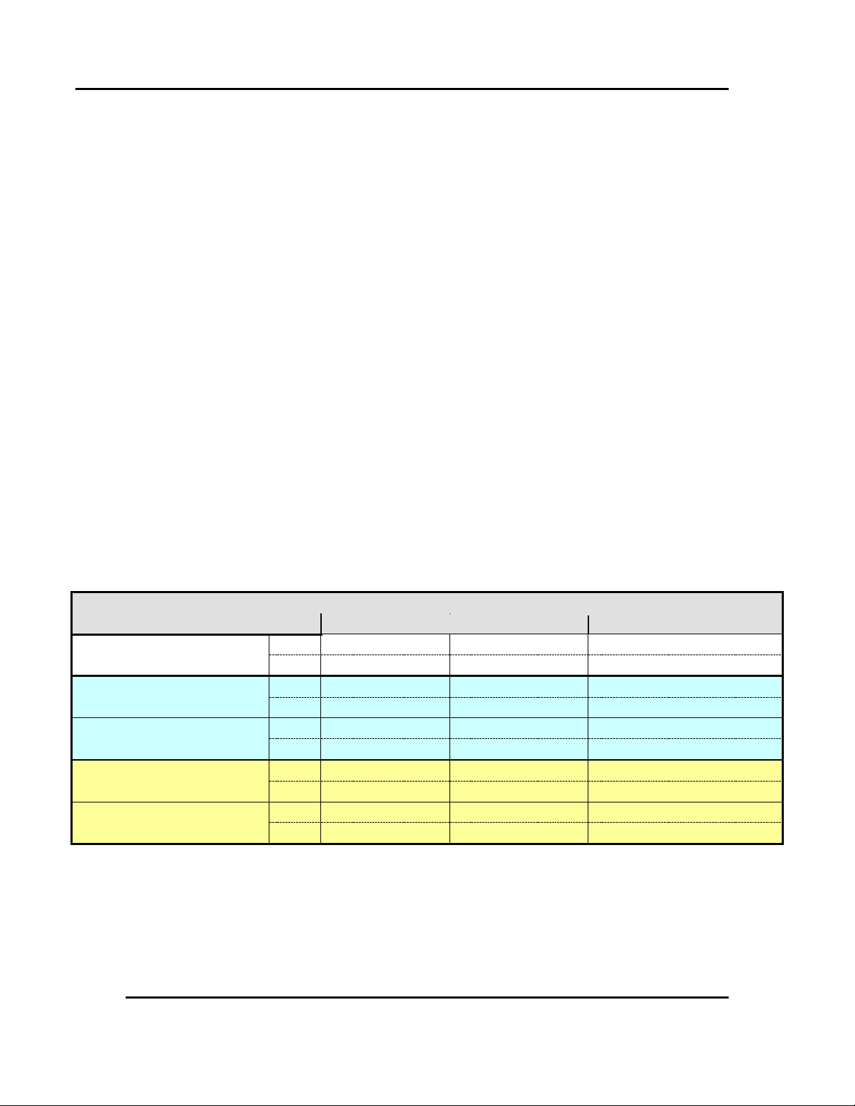
Calculating Parameter Register Addresses
Integer Only
Integer+1
Floating Point
Register Address
Calculation
(hex)
Address
Address + 0x4000
Address x 2 + 0x8000
(dec)
Address
Address + 16384
Address x 2 + 32768
Address Example:
(For Process Variable)
(hex)
0x0407
0x4407
0x880E
(dec)
1031
17415
34830
Data Value Returned:
If actual Value = 23.9 decimal
(hex)
0x00, 0x17
0x00, 0xEF
0x41, 0xBF, 0x33, 0x33
(dec)
23
239
23.9 as floating decimal
Address Example:
(For Selected Setpoint)
(hex)
0x101F
0x501F
0xA03E
(dec)
4127
20511
41022
Data Value Returned:
If Value = 1 (Alternative SP)
(hex)
0x00, 0x01
0x00, 0x0A
0x3F, 0x80, 0x00, 0x00
(dec) 1 10
1.0
as floating decimal
12 Version 2
The Modbus parameter register addresses are detailed in the following sections.
The Access column indicates if a parameter is read only (RO) or if it can also be written to
(R/W).
Note:
Some parameters that do not apply for a particular configuration will accept reads and
writes. Read only parameters will return an exception if an attempt is made to write values
to them.
1.4.8. Data Formats
Data can be read or written in three formats: Integer Only, Integer with 1 Decimal Place and
Floating Point Number.
The Modbus Address column shows the register address for each parameter in integer format.
Other formats can be calculated from the Integer Only address.
When working in Hexadecimal, the format calculations are:
Address for Integer with 1 Decimal Place = Integer address plus 0x4000
Address for Floating Point = Integer address multiplied by 2, plus 0x8000
When working in Decimal, the format calculations are:
Address for Integer with 1 Decimal Place = Integer address plus 16384
Address for Floating Point = Integer address multiplied by 2, plus 32768
Example Register Address Calculations
All rights reserved. No part of the contents of this manual may be reproduced, copied or transmitted in any form or by any
means including graphic, electronic, or mechanical methods or photocopying, recording, or information storage and
retrieval systems without the written permission of Despatch Industries, unless for purchaser's personal use.
Copyright © 2012 by Despatch Industries.
Page 13
ADDRESS LIST Modbus Programming Manual
Parameter Name
Modbus
Address
(Dec)
Modbus
Address
(Hex)
Access
R/W
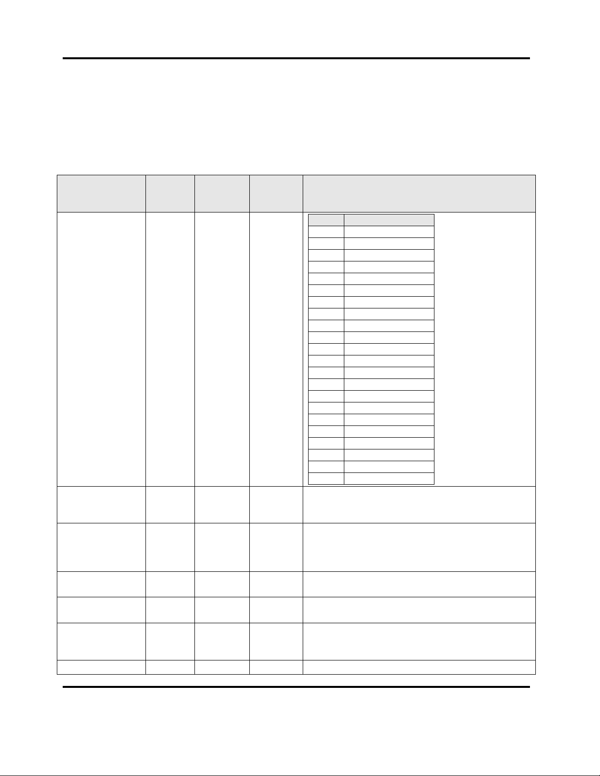
Notes
Input Range
1024
0x0400
R/W
Value
Range
0
B TC
2
C TC
4
D TC
6
E TC
8
J TC
10
K TC
12
L TC
14
N TC
16
R TC
18
S TC
20
T TC
22
P24
24
Pt100
26
NI120
28
0_20mA
29
4_20mA
30
0_50mV
31
10_50mV
32
0_5V
33
1_5V
34
0_10V
35
2_10V
Engineering units
1025
0x0401
R/W
0 = None
1 = Degrees C
2 = Degrees F
Decimal Place
1026
0x0402
R/W
0 = 1234
1 = 123.4
2 = 12.34
3 = 1.234
Process Input
Range Minimum
1027
0x0403
R/W
Process Input
Range Maximum
1028
0x0404
R/W
Process Input
Process variable
offset
1029
0x0405
R/W
Span of the input range
Process Input
1030
0x0406
R/W
Any value between 0.0 and 512.0
13 Version 2
2. Modbus Address List
2.1. Input Parameters
2.1.1. Process Input Parameters
All rights reserved. No part of the contents of this manual may be reproduced, copied or transmitted in any form or by any means
including graphic, electronic, or mechanical methods or photocopying, recording, or information storage and retrieval systems without
the written permission of Despatch Industries, unless for purchaser's personal use.
Copyright © 2012 by Despatch Industries.
Page 14
ABOUT THIS MANUAL Modbus Programming Manual
Parameter Name
Modbus
Address
(Dec)
Modbus
Address
(Hex)
Access
R/W
Notes
Filter time
constant
Process Input
Process Variable
1031
0x0407
R
Process Input
Sensor Break
Flag
1032
0x0408
R
0 = Inactive
1 = Active
Process Input
Under Range
Flag
1033
0x0409
R
0 = Inactive
1 = Active
Process Input
Over Range Flag
1034
0x040A
R
0 = Inactive
1 = Active
Process Input
CJC Enable
1035
0x040B
R/W
0 = Enable
1 = Disabled
Process Input
User Calibration
Type
1085
0x043D
R/W
0 = No User Calibration
1 = Single Point Calibration
2 = Two Point Calibration
Process Input
Low Temperature
Calibration Point
1086
0x043E
R/W
Process Input
Low Calibration
Offset
1087
0x043F
R/W
Process Input
High
Temperature
Calibration Point
1088
0x0440
R/W
Process Input
High Calibration
Offset
1089
0x0441
R/W
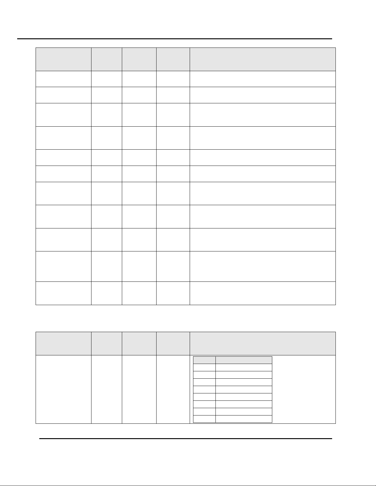
Parameter Name
Modbus
Address
(Dec)
Modbus
Address
(Hex)
Access
R/W
Notes
High Limit Input
Range
9000
0x2328
R/W
Value
Range
0
B TC
2
C TC
4
D TC
6
J TC
10
K TC
14
L TC
18
N TC
20
R TC
14 Version 2
2.1.2. High Limit Input Parameters
All rights reserved. No part of the contents of this manual may be reproduced, copied or transmitted in any form or by any means
including graphic, electronic, or mechanical methods or photocopying, recording, or information storage and retrieval systems without
the written permission of Despatch Industries, unless for purchaser's personal use.
Copyright © 2012 by Despatch Industries.
Page 15
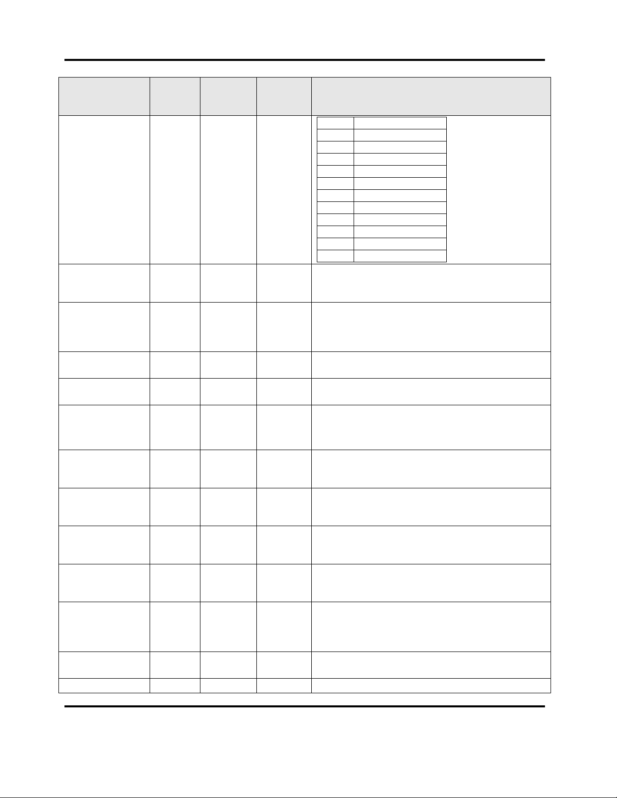
ADDRESS LIST Modbus Programming Manual
Parameter Name
Modbus
Address
(Dec)
Modbus
Address
(Hex)
Access
R/W
Notes
22
S TC
24
T TC
28
P24
30
Pt100 RTD
34
0_20mA
35
4_20mA
36
0_50mV
37
10_50mV
38
0_5V
39
1_5V
40
0_10V
41
2_10V
High Limit Input
Engineering units
9001
0x2329
R/W
0 = None
1 = Degrees C
2 = Degrees F
High Limit Input
Decimal Place
9002
0x232C
R/W
0 = 1234
1 = 123.4
2 = 12.34
3 = 1.234
High Limit Input
Range Minimum
9003
0x232A
R/W
High Limit Input
Range Maximum
9004
0x232B
R/W
High Limit User
Calibration Type
9008
0x2330
R/W
0 = No User Calibration
1 = Single Point Calibration
2 = Two Point Calibration
High Limit Input
Process variable
offset
9009
0x2331
R/W
Span of the input range
Process Input
Low Calibration
Offset
9010
0x2332
R/W
Process Input
Low Temperature
Calibration Point
9011
0x2333
R/W
Process Input
High Calibration
Offset
9012
0x2334
R/W
Process Input
High
Temperature
Calibration Point
9013
0x2335
R/W
High Limit Input
Process Variable
9006
0x232E
R
High Limit Input
9007
0x232F
R
Bit 0 = OPEN
15 Version 2
All rights reserved. No part of the contents of this manual may be reproduced, copied or transmitted in any form or by any means
including graphic, electronic, or mechanical methods or photocopying, recording, or information storage and retrieval systems without
the written permission of Despatch Industries, unless for purchaser's personal use.
Copyright © 2012 by Despatch Industries.
Page 16
ABOUT THIS MANUAL Modbus Programming Manual
Parameter Name
Modbus
Address
(Dec)
Modbus
Address
(Hex)
Access
R/W
Notes
status
Bit 1 = Low
Bit 2 = High
Parameter
Name
Modbus
Address
(Dec)
Modbus
Address
(Hex)
Access
R/W
Notes
Digital input
states
2001
0x7D1
R
Bit Position
Digital input
0 1 1 2 2 3 3
4
Parameter
Name
Modbus
Address
(Dec)
Modbus
Address
(Hex)
Access
R/W
Notes
Usage
2146
0x0862
R/W
Value
Usage
0
None
1
Alarm 1
2
Alarm 2
3
Alarm 3
4
Alarm 4
5
Alarm 5
6
Event 1
7
Event 2
8
Event 3
9
Event 4
10
Event 5
11
Cycle Complete
12
Profile Running
13
Or of Alarms
14
Alarm and Events
Alarm Selection
2148
0x0864
R/W
Value
Selection
0
Alarm 1 or Alarm 2
1
Alarm 1 or Alarm 2 or Alarm 3
2
Alarm 1 or Alarm 2 or Alarm 3 or
Alarm 4
16 Version 2
2.1.3. Digital Inputs
2.2. Output Parameters
2.2.1. Relay Output 1 Parameters
All rights reserved. No part of the contents of this manual may be reproduced, copied or transmitted in any form or by any means
including graphic, electronic, or mechanical methods or photocopying, recording, or information storage and retrieval systems without
the written permission of Despatch Industries, unless for purchaser's personal use.
Copyright © 2012 by Despatch Industries.
Page 17

ADDRESS LIST Modbus Programming Manual
Parameter
Name
Modbus
Address
(Dec)
Modbus
Address
(Hex)
Access
R/W
Notes
3
Alarm 1 or Alarm 2 or Alarm 3 or
Alarm 4 or Alarm 5
Event Alarm
Selection
2150
0x0866
R/W
Value
Selection
0
Alarm 1 or Event 1
1
Alarm 2 or Event 2
2
Alarm 3 or Event 3
3
Alarm 4 or Event 4
4
Alarm 5 or Event 5
Parameter
Name
Modbus
Address
(Dec)
Modbus
Address
(Hex)
Access
R/W
Notes
Usage
2176
0x0880
R/W
Value
Usage
0
None
1
Alarm 1
2
Alarm 2
3
Alarm 3
4
Alarm 4
5
Alarm 5
6
Event 1
7
Event 2
8
Event 3
9
Event 4
10
Event 5
11
Cycle Complete
12
Profile Running
13
Or of Alarms
14
Alarm and Events
Alarm Selection
2178
0x0882
R/W
Value
Selection
0
Alarm 1 or Alarm 2
1
Alarm 1 or Alarm 2 or Alarm 3
2
Alarm 1 or Alarm 2 or Alarm 3 or
Alarm 4
3
Alarm 1 or Alarm 2 or Alarm 3 or
Alarm 4 or Alarm 5
Event Alarm
Selection
2180
0x0884
R/W
Value
Selection
0
Alarm 1 or Event 1
1
Alarm 2 or Event 2
2
Alarm 3 or Event 3
3
Alarm 4 or Event 4
4
Alarm 5 or Event 5
17 Version 2
2.2.2. Relay Output 2 Parameters
All rights reserved. No part of the contents of this manual may be reproduced, copied or transmitted in any form or by any means
including graphic, electronic, or mechanical methods or photocopying, recording, or information storage and retrieval systems without
the written permission of Despatch Industries, unless for purchaser's personal use.
Copyright © 2012 by Despatch Industries.
Page 18

ABOUT THIS MANUAL Modbus Programming Manual
Parameter
Name
Modbus
Address
(Dec)
Modbus
Address
(Hex)
Access
R/W
Notes
Usage
2186
0x088A
R/W
Value
Usage
0
None
1
Alarm 1
2
Alarm 2
3
Alarm 3
4
Alarm 4
5
Alarm 5
6
Event 1
7
Event 2
8
Event 3
9
Event 4
10
Event 5
11
Cycle Complete
12
Profile Running
13
Or of Alarms
14
Alarm and Events
Alarm Selection
2188
0x088C
R/W
Value
Selection
0
Alarm 1 or Alarm 2
1
Alarm 1 or Alarm 2 or Alarm 3
2
Alarm 1 or Alarm 2 or Alarm 3 or
Alarm 4
3
Alarm 1 or Alarm 2 or Alarm 3 or
Alarm 4 or Alarm 5
Event Alarm
Selection
2190
0x088E
R/W
Value
Selection
0
Alarm 1 or Event 1
1
Alarm 2 or Event 2
2
Alarm 3 or Event 3
3
Alarm 4 or Event 4
4
Alarm 5 or Event 5
Parameter
Name
Modbus
Address
(Dec)
Modbus
Address
(Hex)
Access
R/W
Notes
Usage
2205
0x89D
R/W
Value
Usage
0
None
18 Version 2
2.2.3. Relay Output 3 Parameters
2.2.4. Relay Output 4 Parameters
All rights reserved. No part of the contents of this manual may be reproduced, copied or transmitted in any form or by any means
including graphic, electronic, or mechanical methods or photocopying, recording, or information storage and retrieval systems without
the written permission of Despatch Industries, unless for purchaser's personal use.
Copyright © 2012 by Despatch Industries.
Page 19

ADDRESS LIST Modbus Programming Manual
Parameter
Name
Modbus
Address
(Dec)
Modbus
Address
(Hex)
Access
R/W
Notes
1
Alarm 1
2
Alarm 2
3
Alarm 3
4
Alarm 4
5
Alarm 5
6
Event 1
7
Event 2
8
Event 3
9
Event 4
10
Event 5
11
Cycle Complete
12
Profile Running
13
Or of Alarms
14
Alarm and Events
Alarm Selection
2207
0x089F
R/W
Value
Selection
0
Alarm 1 or Alarm 2
1
Alarm 1 or Alarm 2 or Alarm 3
2
Alarm 1 or Alarm 2 or Alarm 3 or
Alarm 4
3
Alarm 1 or Alarm 2 or Alarm 3 or
Alarm 4 or Alarm 5
Event Alarm
Selection
2209
0x08A1
R/W
Value
Selection
0
Alarm 1 or Event 1
1
Alarm 2 or Event 2
2
Alarm 3 or Event 3
3
Alarm 4 or Event 4
4
Alarm 5 or Event 5
Parameter
Name
Modbus
Address
(Dec)
Modbus
Address
(Hex)
Access
R/W
Notes
Usage
2216
0x08A8
R/W
Value
Usage
0
None
1
Alarm 1
2
Alarm 2
3
Alarm 3
4
Alarm 4
5
Alarm 5
6
Event 1
7
Event 2
8
Event 3
9
Event 4
10
Event 5
19 Version 2
2.2.5. Relay Output 5 Parameters
All rights reserved. No part of the contents of this manual may be reproduced, copied or transmitted in any form or by any means
including graphic, electronic, or mechanical methods or photocopying, recording, or information storage and retrieval systems without
the written permission of Despatch Industries, unless for purchaser's personal use.
Copyright © 2012 by Despatch Industries.
Page 20

ABOUT THIS MANUAL Modbus Programming Manual
Parameter
Name
Modbus
Address
(Dec)
Modbus
Address
(Hex)
Access
R/W
Notes
11
Cycle Complete
12
Profile Running
13
Or of Alarms
14
Alarm and Events
Alarm Selection
2218
0x08AA
R/W
Value
Selection
0
Alarm 1 or Alarm 2
1
Alarm 1 or Alarm 2 or Alarm 3
2
Alarm 1 or Alarm 2 or Alarm 3 or
Alarm 4
3
Alarm 1 or Alarm 2 or Alarm 3 or
Alarm 4 or Alarm 5
Event Alarm
Selection
2220
0x08AC
R/W
Value
Selection
0
Alarm 1 or Event 1
1
Alarm 2 or Event 2
2
Alarm 3 or Event 3
3
Alarm 4 or Event 4
4
Alarm 5 or Event 5
Parameter
Name
Modbus
Address
(Dec)
Modbus
Address
(Hex)
Access
R/W
Notes
Linear Output
Usage
2144
0x0860
R/W
Value
Usage
0
None
1
Retransmit PV
2
Retransmit SP
3
Primary (Heat) Control Power
4
Cool Control Power (Only available on
Heat Cool model)
Linear output
range
2223
0x08AF
R/W
Value
Range
0
0 – 5V
1
0 – 10V
2
2 – 10V
3
0 – 20mA
4
4 – 20mA
Retransmit
Minimum
2152
0x0868
R/W
Retransmit
Maximum
2153
0x0869
R/W
20 Version 2
2.2.6. Linear Output Parameters
All rights reserved. No part of the contents of this manual may be reproduced, copied or transmitted in any form or by any means
including graphic, electronic, or mechanical methods or photocopying, recording, or information storage and retrieval systems without
the written permission of Despatch Industries, unless for purchaser's personal use.
Copyright © 2012 by Despatch Industries.
Page 21

ADDRESS LIST Modbus Programming Manual
Parameter Name
Modbus
Address
(Dec)
Modbus
Address
(Hex)
Access
R/W
Notes
Setpoint Minimum
3944
0x0F68
R/W
Limited by input range maximum/minimum
Setpoint
Maximum
3945
0x0F69
R/W
Limited by input range maximum/minimum
Manual/Timer
Mode Setpoint
Value
3960
0x0F78
R/W
Limited by Setpoint maximum/minimum
21 Version 2
2.3. Setpoint Parameters
All rights reserved. No part of the contents of this manual may be reproduced, copied or transmitted in any form or by any means
including graphic, electronic, or mechanical methods or photocopying, recording, or information storage and retrieval systems without
the written permission of Despatch Industries, unless for purchaser's personal use.
Copyright © 2012 by Despatch Industries.
Page 22

ABOUT THIS MANUAL Modbus Programming Manual
Parameter Name
Modbus
Address
(Dec)
Modbus
Address
(Hex)
Access
R/W
Notes
Cycle time
4301
0x10CD
R/W
0.5 to 512.0
Control Type
4310
0x10D6
R/W
0 = Single (Heat Only)
1 = Dual (Heat/Cool)
(Only available on Heat Cool Variant)
Control Action
4311
0x10D7
R/W
0 = Direct
1 = Reverse
Proportional Band 1
4312
0x10D8
R/W
0.0 to 999.9
Secondary (Cool)
Proportional Band
4313
0x10D9
R/W
0.0 to 999.9
(Only available on Heat Cool Variant)
Integral/Reset
4314
0x10DA
R/W
0.0 to 5999
Derivative/Rate
4315
0x10DB
R/W
0.0 to 5999
Bias
4316
0x10DC
R/W
For single control 0 to 100, for Duel control -100
to 100
Overlap/DeadBand
4317
0x10DD
R/W
20% of the proportional band
(Only available on Heat Cool Variant)
On/Off Differential
4320
0x10E0
R/W
0.1 to 100
Heat/Primary Power
Upper limit
4321
0x10E1
R/W
10 to 100% Can not be made smaller than
Heat/Primary Lower limit + 10
Heat/Primary Power
Lower limit
4322
0x10E2
R/W
0 to 90% Can not be made larger than
Heat/Primary Upper limit – 10
Cool/Secondary
Power Upper limit
4323
0x10E3
R/W
10 to 100% Can not be made smaller than
Cool/Secondary Lower limit + 10
Cool/Secondary
Power Lower limit
4324
0x10E4
R/W
0 to 90% Can not be made larger than
Cool/Secondary Upper limit – 10
Pretune Enable
4325
0x10E5
R/W
0 = Disabled
1 = Enabled
Self tune Enable
4326
0x10E6
R/W
0 = Disabled
1 = Enabled
Loop Alarm Type
4327
0x10E7
R/W
1 = Time
2 = Auto
Loop Alarm time
4328
0x10E8
R/W
1 to 5999
Primary Power
4329
0x10E9
R
0 to 100%
Pretune Status
4332
0x10EC
R
0 = Inactive
1 = Active
Self tune Status
4333
0x10ED
R
0 = Inactive
1 = Active
Loop Alarm status
4334
0x10EE
R
0 = Inactive
1 = Active
Preset Power
4335
0x10EF
R/W
0% to 100%
22 Version 2
2.4. Control Parameters
All rights reserved. No part of the contents of this manual may be reproduced, copied or transmitted in any form or by any means
including graphic, electronic, or mechanical methods or photocopying, recording, or information storage and retrieval systems without
the written permission of Despatch Industries, unless for purchaser's personal use.
Copyright © 2012 by Despatch Industries.
Page 23

ADDRESS LIST Modbus Programming Manual
Parameter Name
Modbus
Address
(Dec)
Modbus
Address
(Hex)
Access
R/W
Notes
Auto Pre-tune
4336
0x10F0
R/W
0 = Disabled
1 = Enabled
23 Version 2
All rights reserved. No part of the contents of this manual may be reproduced, copied or transmitted in any form or by any means
including graphic, electronic, or mechanical methods or photocopying, recording, or information storage and retrieval systems without
the written permission of Despatch Industries, unless for purchaser's personal use.
Copyright © 2012 by Despatch Industries.
Page 24

ABOUT THIS MANUAL Modbus Programming Manual
Parameter Name
Modbus
Address
(Dec)
Modbus
Address
(Hex)
Access
R/W
Notes
Alarm Type
6144
0x1800
R/W
0 = High Alarm
1 = Low Alarm
2 = Deviation Alarm
3 = Band Alarm
4 = Loop Alarm
5 = Sensor Break Alarm
Alarm Value
6145
0x1801
R/W
Limited by the input range maximum and minimum
for Alarm types 0 and 1. Limited by the span of the
input range for alarm types 2 and 3. Not used for
alarms 4 and 5.
Alarm Hysteresis
6146
0x1802
R/W
Limited by the span of the input range
Alarm inhibit
6147
0x1803
R/W
0 = Disabled
1 = Enabled
Alarm status
6148
0x1804
R
0 = Inactive
1 = Active
Alarm inhibit
status
6149
0x1805
R
0 = Not inhibited
1 = Inhibited
Rate Minimum
Time Alarm
Value
6150
0x1806
R/W
Parameter Name
Modbus
Address
(Dec)
Modbus
Address
(Hex)
Access
R/W
Notes
Alarm Type
6160
0x1810
R/W
0 = High Alarm
1 = Low Alarm
2 = Deviation Alarm
3 = Band Alarm
4 = Loop Alarm
5 = Sensor Break Alarm
Alarm Value
6161
0x1811
R/W
Limited by the input range maximum and minimum
for Alarm types 0 and 1. Limited by the span of the
input range for alarm types 2 and 3. Not used for
alarms 4 and 5.
Alarm Hysteresis
6162
0x1812
R/W
Limited by the span of the input range
Alarm inhibit
6163
0x1813
R/W
0 = Disabled
1 = Enabled
Alarm status
6164
0x1814
R
0 = Inactive
1 = Active
24 Version 2
2.5. Alarm Parameters
2.5.1. Alarm 1
2.5.2. Alarm 2
All rights reserved. No part of the contents of this manual may be reproduced, copied or transmitted in any form or by any means
including graphic, electronic, or mechanical methods or photocopying, recording, or information storage and retrieval systems without
the written permission of Despatch Industries, unless for purchaser's personal use.
Copyright © 2012 by Despatch Industries.
Page 25

ADDRESS LIST Modbus Programming Manual
Parameter Name
Modbus
Address
(Dec)
Modbus
Address
(Hex)
Access
R/W
Notes
Alarm inhibit
status
6165
0x1815
R
0 = Not inhibited
1 = Inhibited
Rate Minimum
Time Alarm
Value
6166
Parameter Name
Modbus
Address
(Dec)
Modbus
Address
(Hex)
Access
R/W
Notes
Alarm Type
6176
0x1820
R/W
0 = High Alarm
1 = Low Alarm
2 = Deviation Alarm
3 = Band Alarm
4 = Loop Alarm
5 = Sensor Break Alarm
Alarm Value
6177
0x1821
R/W
Limited by the input range maximum and minimum
for Alarm types 0 and 1. Limited by the span of the
input range for alarm types 2 and 3. Not used for
alarms 4 and 5.
Alarm Hysteresis
6178
0x1822
R/W
Limited by the span of the input range
Alarm inhibit
6179
0x1823
R/W
0 = Disabled
1 = Enabled
Alarm status
6180
0x1824
R
0 = Inactive
1 = Active
Alarm inhibit
status
6181
0x1825
R
0 = Not inhibited
1 = Inhibited
Rate Minimum
Time Alarm
Value
6182
0x1826
R/W
Parameter Name
Modbus
Address
(Dec)
Modbus
Address
(Hex)
Access
R/W
Notes
Alarm Type
6192
0x1830
R/W
0 = High Alarm
1 = Low Alarm
2 = Deviation Alarm
3 = Band Alarm
4 = Loop Alarm
5 = Sensor Break Alarm
Alarm Value
6193
0x1831
R/W
Limited by the input range maximum and minimum
for Alarm types 0 and 1. Limited by the span of the
input range for alarm types 2 and 3. Not used for
25 Version 2
2.5.3. Alarm 3
2.5.4. Alarm 4
All rights reserved. No part of the contents of this manual may be reproduced, copied or transmitted in any form or by any means
including graphic, electronic, or mechanical methods or photocopying, recording, or information storage and retrieval systems without
the written permission of Despatch Industries, unless for purchaser's personal use.
Copyright © 2012 by Despatch Industries.
Page 26

ABOUT THIS MANUAL Modbus Programming Manual
Parameter Name
Modbus
Address
(Dec)
Modbus
Address
(Hex)
Access
R/W
Notes
alarms 4 and 5.
Alarm Hysteresis
6194
0x1832
R/W
Limited by the span of the input range
Alarm inhibit
6195
0x1833
R/W
0 = Disabled
1 = Enabled
Alarm status
6196
0x1834
R
0 = Inactive
1 = Active
Alarm inhibit
status
6197
0x1835
R
0 = Not inhibited
1 = Inhibited
Rate Minimum
Time Alarm
Value
6198
0x1836
R/W
Parameter Name
Modbus
Address
(Dec)
Modbus
Address
(Hex)
Access
R/W
Notes
Alarm Type
6208
0x1840
R/W
0 = High Alarm
1 = Low Alarm
2 = Deviation Alarm
3 = Band Alarm
4 = Loop Alarm
5 = Sensor Break Alarm
Alarm Value
6209
0x1841
R/W
Limited by the input range maximum and minimum
for Alarm types 0 and 1. Limited by the span of the
input range for alarm types 2 and 3. Not used for
alarms 4 and 5.
Alarm Hysteresis
6210
0x1842
R/W
Limited by the span of the input range
Alarm inhibit
6211
0x1843
R/W
0 = Disabled
1 = Enabled
Alarm status
6212
0x1844
R
0 = Inactive
1 = Active
Alarm inhibit
status
6213
0x1845
R
0 = Not inhibited
1 = Inhibited
Rate Minimum
Time Alarm
Value
6214
0x1846
R/W
Parameter Name
Modbus
Address
(Dec)
Modbus
Address
(Hex)
Access
R/W
Notes
Alarm Value
9022
0x233E
R/W
26 Version 2
2.5.5. Alarm 5
2.5.6. High Limit Alarm Parameters
All rights reserved. No part of the contents of this manual may be reproduced, copied or transmitted in any form or by any means
including graphic, electronic, or mechanical methods or photocopying, recording, or information storage and retrieval systems without
the written permission of Despatch Industries, unless for purchaser's personal use.
Copyright © 2012 by Despatch Industries.
Page 27

ADDRESS LIST Modbus Programming Manual
Parameter Name
Modbus
Address
(Dec)
Modbus
Address
(Hex)
Access
R/W
Notes
Alarm Hysteresis
9023
0x233F
R/W
Limited by the span of the input range
Alarm status
9007
0x232F
R
0 = Inactive
1 = Active
27 Version 2
All rights reserved. No part of the contents of this manual may be reproduced, copied or transmitted in any form or by any means
including graphic, electronic, or mechanical methods or photocopying, recording, or information storage and retrieval systems without
the written permission of Despatch Industries, unless for purchaser's personal use.
Copyright © 2012 by Despatch Industries.
Page 28

ABOUT THIS MANUAL Modbus Programming Manual
Parameter Name
Modbus
Address
(Dec)
Modbus
Address
(Hex)
Access
R/W
Notes
Log Interval
7550
0x1D7E
R/W
0 = Every second
1 = Every 2 seconds
2 = Every 5 seconds
3 = Every 10 seconds
4 = Every 15 seconds
5 = Every 30 seconds
6 = Every Minute
7 = Every 2 Minutes
8 = Every 5 Minutes
9 = Every 10 Minutes
10 = Every 15 Minutes
11 = Every 30 Minutes
12 = Every 60 Minutes
Log Mode
7551
0x1D7F
R/W
0 = Record until memory used
1 = Continues FIFO
Memory
Remaining
7554
0x1D82
R
In Bytes
Time Remaining
7555
0x1D83
R
In seconds
Parameter Name
Modbus
Address
(Dec)
Modbus
Address
(Hex)
Access
R/W
Notes
Date format
7868
0x1EBC
R
0 = dd/mm/yyyy (European Default)
1 = mm/dd/yyyy (USA Default)
Time
7869
0x1EBD
R/W
In seconds from midnight
Date
7870
0x1EBE
R/W
Day of the week
7872
0x1EC0
R/W
1 = Monday
2 = Tuesday
3 = Wednesday
4 = Thursday
5 = Friday
6 = Saturday
7 = Sunday
28 Version 2
2.6. Logger parameters (Data Logger)
2.6.1. Data Recorder
2.6.2. Real Time Clock
All rights reserved. No part of the contents of this manual may be reproduced, copied or transmitted in any form or by any means
including graphic, electronic, or mechanical methods or photocopying, recording, or information storage and retrieval systems without
the written permission of Despatch Industries, unless for purchaser's personal use.
Copyright © 2012 by Despatch Industries.
Page 29

ADDRESS LIST Modbus Programming Manual
Parameter Name
Modbus
Address
(Dec)
Modbus
Address
(Hex)
Access
R/W
Notes
Key State
7669
0x1DF5
R
Current state of the keys
Key Debounce
7670
0x1DF6
R/W
Not currently supported
Parameter Name
Modbus
Address
(Dec)
Modbus
Address
(Hex)
Access
R/W
Notes
LED 1 Label
7660
0x1DEC
R/W
LED 2 Label
7661
0x1DED
R/W
LED 3 Label
7662
0x1DEE
R/W
LED 4 Label
7663
0x1DEF
R/W
Backlight Colour
7668
0x1DF4
R/W
0 = Green to Red on Alarm
1 = Red to Green on Alarm
2 = Green
3 = Red
Parameter Name
Modbus
Address
(Dec)
Modbus
Address
(Hex)
Access
R/W
Notes
Language
7675
0x1DFB
R/W
0 = Downloaded Language
1 = English
LCD Contrast
7676
0x1DFC
R/W
0 to 100
Invert LCD
7677
0x1DFD
R/W
0 = Normal
1 = Inverted
Setup Lock Code
7678
0x1DFE
R/W
Default 10
Configuration
Lock Code
7679
0x1DFF
R/W
Default 10
Tune Lock Code
7680
0x1E00
R/W
Default 10
USB Lock Code
7683
0x1E03
R/W
Default 10
Recorder Lock
Code
7684
0x1E04
R/W
Default 10
Profile Lock Code
7682
0x1E02
R/W
Default 10
29 Version 2
2.7. Display Parameters
2.7.1. Keys
2.7.2. LEDs
2.7.3. HMI
All rights reserved. No part of the contents of this manual may be reproduced, copied or transmitted in any form or by any means
including graphic, electronic, or mechanical methods or photocopying, recording, or information storage and retrieval systems without
the written permission of Despatch Industries, unless for purchaser's personal use.
Copyright © 2012 by Despatch Industries.
Page 30

ABOUT THIS MANUAL Modbus Programming Manual
Parameter Name
Modbus
Address
(Dec)
Modbus
Address
(Hex)
Access
R/W
Notes
Serial number hi
210
0x00D2
R
Can only be set through diagnostics mode,
Refer to document ENG2491
Serial number lo
211
0x00D3
R
Can only be set through diagnostics mode,
Refer to document ENG2491
Serial number line
212
0x00D4
R
Can only be set through diagnostics mode,
Refer to document ENG2491
Serial number qty
213
0x00D5
R
Can only be set through diagnostics mode,
Refer to document ENG2491
Date of
manufacture (Day)
370
0x0172
R
Can only be set through diagnostics mode,
Refer to document ENG2491
Date of
manufacture
(Month)
371
0x0173
R
Can only be set through diagnostics mode,
Refer to document ENG2491
Date of
manufacture (Year)
372
0x0174
R
Can only be set through diagnostics mode,
Refer to document ENG2491
Software PRL
208
0x00D0
R
Can only be set through diagnostics mode,
Refer to document ENG2491
Hardware PRL
207
0x00CF
R
Can only be set through diagnostics mode,
Refer to document ENG2491
Software version
201
0x00C9
R
Can only be set through diagnostics mode,
Refer to document ENG2491
Hardware option
200
0x00C8
R
Can only be set through diagnostics mode,
Refer to document ENG2491
Manufactures ID
216
0x00D8
R
Can only be set through diagnostics mode,
Refer to document ENG2491
Unit ID
203
0x00CB
R
Should never be set by automatic test
equipment
Version Major
217
0x00D9
R
Should never be set by automatic test
equipment
Version Minor
218
0x00DA
R
Should never be set by automatic test
equipment
OP Version
202
0x00CA
R
Should never be set by automatic test
equipment
Sub Version
204
0x00CC
R
Should never be set by automatic test
equipment
Software type
206
0x00CE
R
Should never be set by automatic test
equipment
OEM Code hi
373
0x0175
R
Should never be set by automatic test
equipment
OEM Code lo
374
0x0176
R
Should never be set by automatic test
30 Version 2
2.7.4. System Data
All rights reserved. No part of the contents of this manual may be reproduced, copied or transmitted in any form or by any means
including graphic, electronic, or mechanical methods or photocopying, recording, or information storage and retrieval systems without
the written permission of Despatch Industries, unless for purchaser's personal use.
Copyright © 2012 by Despatch Industries.
Page 31

ADDRESS LIST Modbus Programming Manual
Parameter Name
Modbus
Address
(Dec)
Modbus
Address
(Hex)
Access
R/W
Notes
equipment
Contact Details line
1
400
0x0190
R/W
26 characters of text
Contact Details line
2
401
0x0191
R/W
26 characters of text
Contact Details line
3
402
0x0192
R/W
26 characters of text
Contact Details line
4
403
0x0193
R/W
26 characters of text
Contact Details line
5
404
0x0194
R/W
26 characters of text
Contact Details line
6
405
0x0195
R/W
26 characters of text
Contact Details line
7
406
0x0196
R/W
26 characters of text
Communications
Address
413
0x019D
R/W
Communications
Baud rate
414
0x019E
R/W
Communications
Parity
415
0x019F
R/W
31 Version 2
All rights reserved. No part of the contents of this manual may be reproduced, copied or transmitted in any form or by any means
including graphic, electronic, or mechanical methods or photocopying, recording, or information storage and retrieval systems without
the written permission of Despatch Industries, unless for purchaser's personal use.
Copyright © 2012 by Despatch Industries.
Page 32

ABOUT THIS MANUAL Modbus Programming Manual
Parameter Name
Modbus
Address
(Dec)
Modbus
Address
(Hex)
Access
R/W
Notes
Mode Selection
8285
0x205D
R/W
0 = Do Nothing
1 = Manual Mode
2 = Timer Mode
3 = Profile Mode
4 = Mode Selection
Digital input
Profile Selection
control Enable
8273
0x2051
R/W
0 = HMI or Comms selection
1 = Digital input profile selection
Current Mode
Selected
8280
0x2058
RO
0 = Mode Selection
1 = Configuration
2 = Manual
3 = Timer
4 = Profile
Parameter Name
Modbus
Address
(Dec)
Modbus
Address
(Hex)
Access
R/W
Notes
Manual Mode
Recovery
8278
0x2056
R/W
0 = Control Off
1 = Recover to Mode
Manual Mode
recovery Time
8279
0x2057
R/W
Value in seconds
Manual Mode
Status
8281
0x2059
RO
0 = Mode Stopped
1 = Mode Running
Manual Mode
Relay Status
2170
0x087A
RO
Bit 0 = Relay 1
Bit 1 = Relay 2
Bit 2 = Relay 3
Bit 3 = Relay 4
Bit 4 = Relay 5
Manual Mode
Control
8283
0x205B
R/W
0 = Stop Manual Mode
1 = Start Manual Mode
3 = Waiting for Command
Manual Mode
Control Setpoint
3960
0x0F78
R/W
Manual Mode
Relay 1
8249
0x2039
R/W
0 = Off
1 = On
Manual Mode
Relay 2
8250
0x203A
R/W
0 = Off
1 = On
Manual Mode
Relay 3
8251
0x203B
R/W
0 = Off
1 = On
32 Version 2
2.8. Mode Controls
2.8.1. General Mode Control
2.8.2. Manual Mode Parameters
All rights reserved. No part of the contents of this manual may be reproduced, copied or transmitted in any form or by any means
including graphic, electronic, or mechanical methods or photocopying, recording, or information storage and retrieval systems without
the written permission of Despatch Industries, unless for purchaser's personal use.
Copyright © 2012 by Despatch Industries.
Page 33

ADDRESS LIST Modbus Programming Manual
Parameter Name
Modbus
Address
(Dec)
Modbus
Address
(Hex)
Access
R/W
Notes
Manual Mode
Relay 4
8252
0x203C
R/W
0 = Off
1 = On
Parameter Name
Modbus
Address
(Dec)
Modbus
Address
(Hex)
Access
R/W
Notes
Timer Mode
Recovery
8275
0x2053
R/W
0 = Control Off
1 = Restart Timer
2 = Continue Timer
Timer Mode
Recovery Time
8276
0x2054
R/W
Value in seconds
Timer Mode Auto
Hold Value
8272
0x2050
R/W
Timer Mode
Status
8282
0x205A
RO
0 = Mode Stopped
1 = Mode Running
Timer Mode
Relay Status
2170
0x087A
RO
Bit 0 = Relay 1
Bit 1 = Relay 2
Bit 2 = Relay 3
Bit 3 = Relay 4
Bit 4 = Relay 5
Timer Mode
Control
8284
0x205C
R/W
0 = Stop Timer
1 = Start Timer
3 = Waiting for Command
Timer Time
8270
0x204E
R/W
Time in seconds
Current
Remaining Time
of timer
8238
0x202E
RO
Value in seconds. The amount of time remaining
for the active segment.
Timer Mode
Control Setpoint
3960
0x0F78
R/W
Timer Mode
Relay 1
8249
0x2039
R/W
0 = Off
1 = On
Timer Mode
Relay 2
8250
0x203A
R/W
0 = Off
1 = On
Timer Mode
Relay 3
8251
0x203B
R/W
0 = Off
1 = On
Timer Mode
Relay 4
8252
0x203C
R/W
0 = Off
1 = On
33 Version 2
2.8.3. Timer Mode Parameters
All rights reserved. No part of the contents of this manual may be reproduced, copied or transmitted in any form or by any means
including graphic, electronic, or mechanical methods or photocopying, recording, or information storage and retrieval systems without
the written permission of Despatch Industries, unless for purchaser's personal use.
Copyright © 2012 by Despatch Industries.
Page 34

ABOUT THIS MANUAL Modbus Programming Manual
Parameter Name
Modbus
Address
(Dec)
Modbus
Address
(Hex)
Access
R/W
Notes
Currently
Selected Profile
8243
0x2033
R/W
Value between 0 and 63
Currently Active
Segment
8244
0x2034
RO
Value between 0 and 255
Current Setpoint
8256
0x2040
RO
Currently
Running
Segment Type
8258
0x2042
RO
0 = None
1 = Ramp Up
2 = Step
3 = Dwell
4 = Hold
5 = Loop
6 = Join
7 = End
8 = Ramp Down
Start Delay Time
8233
0x2029
RO
Value in seconds. The current start delay time
remaining
Current Time of
the active
segment
8237
0x202D
RO
Value in seconds. The amount of time the
segment has been running
Current
Remaining Time
of segment
8238
0x202E
RO
Value in seconds. The amount of time remaining
for the active segment.
Current Time of
the running
Profile
8235
0x202B
RO
Value in seconds. The amount of time the profile
has been running.
Current
Remaining
Profile Time
8236
0x202C
RO
Value in seconds. The amount of time remaining
for the complete profile.
Total Hold Time
8239
0x202F
RO
Value in seconds. The total amount of time the
profile has been held for.
Profile Mode
Relay Status
2170
0x087A
RO
Bit 0 = Relay 1
Bit 1 = Relay 2
Bit 2 = Relay 3
Bit 3 = Relay 4
Bit 4 = Relay 5
Event 1 Status
8249
0x2039
RO
0 = Inactive
1 = Active
Event 2 Status
8250
0x203A
RO
0 = Inactive
1 = Active
Event 3 Status
8251
0x203B
RO
0 = Inactive
1 = Active
Event 4 Status
8252
0x203C
RO
0 = Inactive
1 = Active
Profile Selection
8243
0x2033
R/W
Value between 0 and 63 to select the profile to run
34 Version 2
2.8.4. Profile Mode Parameters
All rights reserved. No part of the contents of this manual may be reproduced, copied or transmitted in any form or by any means
including graphic, electronic, or mechanical methods or photocopying, recording, or information storage and retrieval systems without
the written permission of Despatch Industries, unless for purchaser's personal use.
Copyright © 2012 by Despatch Industries.
Page 35

ADDRESS LIST Modbus Programming Manual
Parameter Name
Modbus
Address
(Dec)
Modbus
Address
(Hex)
Access
R/W
Notes
Profile Control
8245
0x2035
R/W
0 = Do Nothing
1 = Run the selected profile
2 = Hold the currently running profile
3 = Abort the currently running profile
4 = Jump to the next segment
5 = Release a held profile
6 = Exit the profile control once the profile has
completed and is holding the last setpoint
Active Profile
Name
8259
0x2043
R
The currently selected profile name
Profile Status
8241
0x2031
R
0 = Stopped
1 = Running
2 = Held
3 = Delayed
4 = Error
5 = Aborted
6 = Ended
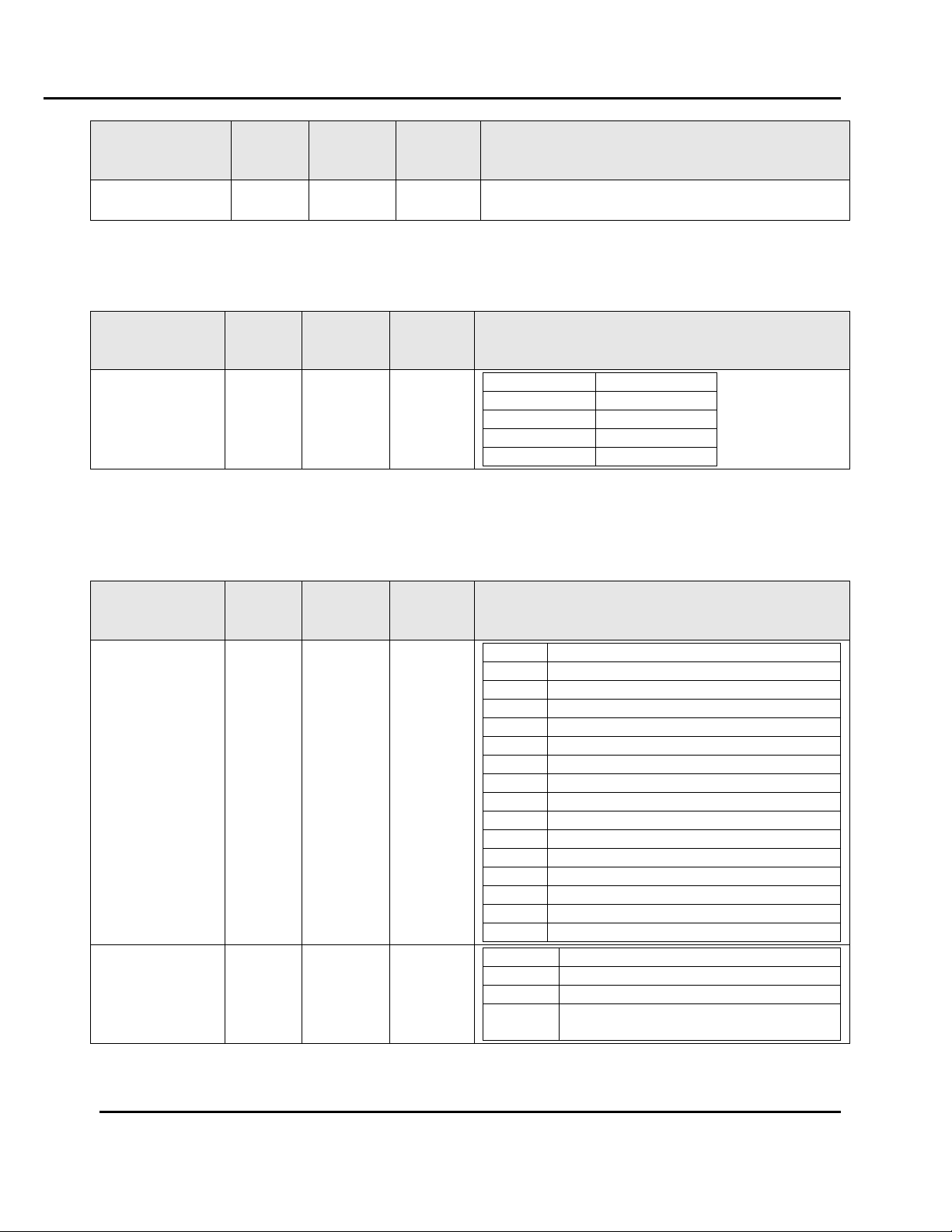
Command Code
Value Decimal
Value Hex
Function
CP
17232
0x4350
Create Profile
EP
17744
0x4550
Edit Profile
WP
22352
0x5750
Write Profile
WS
22355
0x5753
Create Segment
IS
18771
0x4953
Insert Segment
ES
17747
0x4553
Edit a Segment
DP
17488
0x4450
Delete a Profile
DA
17473
0x4441
Delete all profiles
DS
17491
0x4453
Delete a Segment
SR
21330
0x5352
Get the number of segments remaining
RP
21072
0x5250
Read Profile Header
35 Version 2
2.9. Uploading and Downloading of Profiles
The information in this section is intended for advanced users writing their own software code.
Most users will create or edit profiles using the instrument keypad or via BlueControl. Either
method allows quick and easy editing of profiles.
Advanced users can setup or edit profiles by writing to the Profile Configuration parameter at
address 8198 (0x2006). This can only be accessed by using Modbus function code 23 (0x17). The
instrument replies with a status message.
When creating a new profile the steps below must be followed exactly, either to create a profile at
the next available position, or at a position that you specify.
Each message in the sequence includes a 2 byte Command Code that tells the instrument the
purpose of the message, and therefore the meaning of the data contained in it.
The command codes support by this instrument are:
All rights reserved. No part of the contents of this manual may be reproduced, copied or transmitted in any form or by any means
including graphic, electronic, or mechanical methods or photocopying, recording, or information storage and retrieval systems without
the written permission of Despatch Industries, unless for purchaser's personal use.
Copyright © 2012 by Despatch Industries.
Page 36

ADDRESS LIST Modbus Programming Manual
Command Code
Value Decimal
Value Hex
Function
RS
21075
0x5253
Read Segment
PN
20558
0x504E
Read Profile Name
PS
20563
0x5053
Read the profiler memory status
36 Version 2
The following rules apply when creating a profile over communications:
Profiles must always be terminated with an end segment.
Segments cannot be added after an end segment has been added.
All changes made to the selected profile are immediately saved in the instrument.
2.9.1. Instruction Sequence to create a profile at the next available position
1. Create a profile by writing the profile header data using the Command Code value CP
(0x43, 0x50). This starts the profile creation process by reserving a profile memory slot.
The profile number is returned by the instrument in the Edit Response Message.
2. Write the first segment using the Command Code value Code WS (0x57, 0x53). This
command will fill the next available segment position and link it to the profile created in
step 1.
3. Write the second segment, again using Command Code WS. This fills the next available
segment position and links it to the segment created in step 2.
4. Continue writing segments until the profile is complete (whilst remaining within the
overall limit of 255 segments for all profiles combined). Each of these segments fills the
next available position and links it to the previous segment specified.
5. The very last segment of the profile must be one of the end type segments. Thereafter, no
more segments can be added to the specified profile. To add a segment to an existing
profile the insert segment command must be used.
2.9.2. Instruction Sequence to create a profile at a specified profile position
CAUTION:
If this profile number is already in use then the profile header data is overwritten but the segments
associated with it are kept.
1. Determine which profile positions are being used by using the Command Code value PS
(0x50, 0x53). This command will return a list of all the profile positions currently being
used.
2. Choose a location that is not being used and write the profile header data using the
Command Code value WP (0x57, 0x50).
The profile number is echoed back by the instrument in the Edit Response Message.
3. Write the first segment using the Command Code value Code WS (0x57, 0x53). This
command will fill the next available segment position and link it to the profile created in
step 1.
4. Write the second segment, again using Command Code WS. This fills the next available
segment position and links it to the segment created in step 2.
Copyright © 2012 by Despatch Industries.
All rights reserved. No part of the contents of this manual may be reproduced, copied or transmitted in any form or by any
means including graphic, electronic, or mechanical methods or photocopying, recording, or information storage and
retrieval systems without the written permission of Despatch Industries, unless for purchaser's personal use.
Page 37

Modbus Programming Manual ADDRESS LIST
Creating A Profile Header - Request (to instrument)
Field Name
Data
Comments
(Dec)
(Hex)
Unit Address
A/R
A/R
The ID address of the instrument.
Function Code
23
17
Requires the multi read/write function.
Read Start Address High Byte
32
20
Read Start Address Low Byte
06
06
Read Quantity Of Registers High Byte
00
00
Read Quantity Of Registers Low Byte
01
01
Write Start Address High Byte
32
20
Write Start Address Low Byte
06
06
Write Quantity Of Registers High Byte
00
00
Write Quantity Of Registers Low Byte
20
14
Byte Count
40
28
38dec / 0x26hex creating a profile at the
next available location.
Command Code High Byte
67
43
Create Profile (CP) = 17232dec / 0x4350hex
Command Code Low Byte
80
50
Profile Name Character 1
A/R
A/R
The ASCII codes equivalent to each of the
Profile Name Character 2
A/R
A/R
Version 2 37
5. Continue writing segments until the profile is complete (whilst remaining within the
overall limit of 255 segments for all profiles combined). Each of these segments fills the
next available position and links it to the previous segment specified.
6. The very last segment of the profile must be one of the end type segments. Thereafter, no
more segments can be added to the specified profile. To add a segment to an existing
profile the insert segment command must be used.
2.9.3. Instruction Sequence to edit an existing Profile Header
When a profile header is changed, the segments associated with it remain unchanged. They must
be edited separately if required.
1. Determine the number of the profile to be edited. Use the Command Code value PS
(0x50, 0x53) which returns a list of all profile positions/numbers currently in use.
2. Write a new profile header data using the Command Code value EP (0x45, 0x50).
The profile number is echoed back by the instrument in the Edit Response Message.
2.9.4. Instruction Sequence to read a profile
1. Use the command RP to read the profile header data
2. Use the command RS to read the 1st segment’s data
3. Use the command RS to read the 2nd segment’s data.
4. Repeat steps 2 and 3 until an end segment is reached.
2.9.5. Profile Command Code Descriptions
2.9.5.1. Creating a profile header (Command Code CP)
All rights reserved. No part of the contents of this manual may be reproduced, copied or transmitted in any form or by any
means including graphic, electronic, or mechanical methods or photocopying, recording, or information storage and
retrieval systems without the written permission of Despatch Industries, unless for purchaser's personal use.
Copyright © 2012 by Despatch Industries.
Page 38

ADDRESS LIST Modbus Programming Manual
Creating A Profile Header - Request (to instrument)
Field Name
Data
Comments
(Dec)
(Hex)
Profile Name Character 3
A/R
A/R
16 characters of the profile name, e.g. :
A = 65dec / 0x41, B = 66dec / 0x42 etc
a = 97dec / 0x61, b = 98dec / 0x62 etc
Note: Only valid characters from the
instruments supported character set
should be used
The space character (32dec / 0x20hex) is
used to fill any unused characters at the end
of the name.
Characters 9 to 16 are not supported and
should be written to 32dec / 0x20hex
Profile Name Character 4
A/R
A/R
Profile Name Character 5
A/R
A/R
Profile Name Character 6
A/R
A/R
Profile Name Character 7
A/R
A/R
Profile Name Character 8
A/R
A/R
Profile Name Character 9
32
20
Profile Name Character 10
32
20
Profile Name Character 11
32
20
Profile Name Character 12
32
20
Profile Name Character 13
32
20
Profile Name Character 14
32
20
Profile Name Character 15
32
20
Profile Name Character 16
32
20
Profile Start Signal High Byte
00
00
0 = No delay, 1 = After delay, 2 = At
Time/day
Profile Start Signal Low Byte
A/R
A/R
Profile Start Time (Byte 4 - High)
Floating point number
Profile Start Time (Byte 3)
Profile Start Time (Byte 2)
Profile Start Time (Byte 1 - Low)
Profile Start Day High Byte
00
00
1 = Monday, 2 = Tuesday, 3 = Wednesday,
4 = Thursday, 5 = Friday, 6 = Saturday,
7 = Sunday, 8 = Monday to Friday,
9 = Monday to Saturday,
10 = Saturday And Sunday, 11= All Week
Profile Start Day Low Byte
A/R
A/R
Profile Starting Setpoint High
00
00
1 = Current Process Variable Value
Profile Starting Setpoint Low
01
01
Profile Recovery High Byte
00
00
0 = Control to off, 1 = Restart profile,
2 = Maintain last profile setpoint,
4 = Continue profile from where it was when
power failed
Profile Recovery Low Byte
A/R
A/R
Profile Recovery Time (Byte 4 - high)
Floating point number
Profile Recovery Time (Byte 3)
Profile Recovery Time (Byte 2)
Profile Recovery Time (Byte 1 - Low)
Profile Abort action High Byte
00
00
0 = Control to off
1 = Maintain last profile setpoint
Profile Abort Action Low Byte
A/R
A/R
Profile Cycles High Byte
A/R
A/R
1 to 9999 or 10,000 for “Infinite”
Profile Cycles Low Byte
A/R
A/R
Profile Tracks High Byte
00
00
Always set to 1
Profile Tracks Low Byte
01
01
CRC High Byte
A/R
A/R
CRC Low Byte
A/R
A/R
38 Version 2
The instrument replies to this message with an Edit Response Message Section 2.9.5.9.
All rights reserved. No part of the contents of this manual may be reproduced, copied or transmitted in any form or by any
means including graphic, electronic, or mechanical methods or photocopying, recording, or information storage and
retrieval systems without the written permission of Despatch Industries, unless for purchaser's personal use.
Copyright © 2012 by Despatch Industries.
Page 39

Modbus Programming Manual ADDRESS LIST
Creating Or Editing A Profile Header at a specific location - Request (to instrument)
Field Name
Data
Comments
(Dec)
(Hex)
Unit Address
A/R
A/R
The ID address of the instrument.
Function Code
23
17
Requires the multi read/write function.
Read Start Address High Byte
32
20
Read Start Address Low Byte
06
06
Read Quantity Of Registers High Byte
00
00
Read Quantity Of Registers Low Byte
01
01
Write Start Address High Byte
32
20
Write Start Address Low Byte
06
06
Write Quantity Of Registers High Byte
00
00
Write Quantity Of Registers Low Byte
21
15
Byte Count
42
2A
42dec / 0x2Ahex if creating a profile at a
specified location, or editing a profile.
Command Code High Byte
69 or 87
45 or 57
Edit Profile (EP) = 17744dec / 0x4550hex
Write Profile (WP) = 23352dec / 0x5750hex
Command Code Low Byte
80
50
Profile Number High Byte
A/R
A/R
The profile number can be anything between
0 and 64
Profile Number Low Byte
A/R
A/R
Profile Name Character 1
A/R
A/R
The ASCII codes equivalent to each of the
16 characters of the profile name, e.g. :
A = 65dec / 0x41, B = 66dec / 0x42 etc
a = 97dec / 0x61, b = 98dec / 0x62 etc
Note: Only valid characters from the
instruments supported character set
should be used
The space character (32dec / 0x20hex) is
used to fill any unused characters at the end
of the name
Characters 9 to 16 are not supported and
should be written to 32dec / 0x20hex
.
Profile Name Character 2
A/R
A/R
Profile Name Character 3
A/R
A/R
Profile Name Character 4
A/R
A/R
Profile Name Character 5
A/R
A/R
Profile Name Character 6
A/R
A/R
Profile Name Character 7
A/R
A/R
Profile Name Character 8
A/R
A/R
Profile Name Character 9
32
20
Profile Name Character 10
32
20
Profile Name Character 11
32
20
Profile Name Character 12
32
20
Profile Name Character 13
32
20
Profile Name Character 14
32
20
Profile Name Character 15
32
20
Profile Name Character 16
32
20
Profile Start Signal High Byte
00
00
0 = No delay, 1 = After delay, 2 = At
Time/day
Profile Start Signal Low Byte
A/R
A/R
Profile Start Time (Byte 4 - High)
Floating point number
Profile Start Time (Byte 3)
Profile Start Time (Byte 2)
Profile Start Time (Byte 1 - Low)
Profile Start Day High Byte
00
00
1 = Monday, 2 = Tuesday, 3 = Wednesday,
4 = Thursday, 5 = Friday, 6 = Saturday,
7 = Sunday, 8 = Monday to Friday,
9 = Monday to Saturday,
10 = Saturday And Sunday, 11= All Week
Profile Start Day Low Byte
A/R
A/R
Profile Starting Setpoint High
00
00
1 = Current Process Variable Value
Version 2 39
2.9.5.2. Editing/Creating a profile header at a location (Command Code EP or WP)
All rights reserved. No part of the contents of this manual may be reproduced, copied or transmitted in any form or by any
means including graphic, electronic, or mechanical methods or photocopying, recording, or information storage and
retrieval systems without the written permission of Despatch Industries, unless for purchaser's personal use.
Copyright © 2012 by Despatch Industries.
Page 40

ADDRESS LIST Modbus Programming Manual
Creating Or Editing A Profile Header at a specific location - Request (to instrument)
Field Name
Data
Comments
(Dec)
(Hex)
Profile Starting Setpoint Low
01
01
Profile Recovery High Byte
00
00
0 = Control to off, 1 = Restart profile,
2 = Maintain last profile setpoint,
4 = Continue profile from where it was when
power failed
Profile Recovery Low Byte
A/R
A/R
Profile Recovery Time (Byte 4 - high)
Floating point number
Profile Recovery Time (Byte 3)
Profile Recovery Time (Byte 2)
Profile Recovery Time (Byte 1 - Low)
Profile Abort action High Byte
00
00
0 = Control to off
1 = Maintain last profile setpoint
Profile Abort Action Low Byte
A/R
A/R
Profile Cycles High Byte
A/R
A/R
1 to 9999 or 10,000 for “Infinite”
Profile Cycles Low Byte
A/R
A/R
CRC High Byte
A/R
A/R
CRC Low Byte
A/R
A/R
Creating Segments - Request (to instrument)
Field Name
Data
Comments
(Dec)
(Hex)
Unit Address
A/R
A/R
The ID address of the instrument.
Function Code
23
17
Requires the multi read/write function.
Read Start Address High Byte
32
20
Read Start Address Low Byte
06
06
Read Quantity Of Registers High
00
00
Read Quantity Of Registers Low
01
01
Write Start Address High
32
20
Write Start Address Low
06
06
Write Quantity Of Registers High
00
00
Write Quantity Of Registers Low
11
0B
Create Segment (WS) = 11dec / 0x0Bhex
Byte Count
22
16
Create Segment (WS) = 22dec / 0x16hex
Command Code High Byte
87
57
Create Segment (WS) = 22355dec /
0x5753hex
Command Code Low Byte
83
53
Profile Number High Byte
A/R
A/R
The profile number can be anything between
0 and 64
Profile Number Low Byte
A/R
A/R
Segment Type High Byte
00
00
0 = Ramp Time, 1 = Ramp Rate,
2 = Step, 3 = Dwell, 4 = Hold, 5 = Loop
6 = Join, 7 = End, 8 = Repeat sequence
then end
Segment Type Low Byte
A/R
A/R
Segment Info A (Byte 4 - High)
Floating point number
The meaning of the data contained in
Segment Info A depends on the type of
segment it relates to. See section 12.5.5.
Segment Info A (Byte 3)
Segment Info A (Byte 2)
40 Version 2
The instrument replies to this message with an Edit Response Message Section 2.9.5.9.
2.9.5.3. Creating a Segment (Command Code WS)
Creating new segments is only possible when a new profile is being created (see above for
instruction for creating a profile at the next available position, or at a position that you specify).
An error is returned if the correct sequence is not followed.
All rights reserved. No part of the contents of this manual may be reproduced, copied or transmitted in any form or by any
means including graphic, electronic, or mechanical methods or photocopying, recording, or information storage and
retrieval systems without the written permission of Despatch Industries, unless for purchaser's personal use.
Copyright © 2012 by Despatch Industries.
Page 41

Modbus Programming Manual ADDRESS LIST
Creating Segments - Request (to instrument)
Field Name
Data
Comments
(Dec)
(Hex)
Segment Info A (Byte 1 - Low)
Segment Info B (Byte 4 - High)
Floating point number
The meaning of the data contained in
Segment Info B depends on the type of
segment it relates to. See section 12.5.5.
Segment Info B (Byte 3)
Segment Info B (Byte 2)
Segment Info B (Byte 1 - Low)
Auto Hold Type High Byte
A/R
A/R
0 = Auto-Hold Off, 1 = Hold above SP,
2 = Hold below SP,3 - Hold above and
below SP
Auto Hold Type Low Byte
A/R
A/R
Auto Hold Value (Byte 4 - High)
Floating point number
Auto Hold Value (Byte 3)
Auto Hold Value (Byte 2)
Auto Hold Value (Byte 1 - Low)
Events High Byte
00
00
The status of the five events are defined by
the lowest 5 bits of the low byte. A bit value
of 1 signifies the event is on.
Bit 0 = event 1, bit 1 = event 2, bit 3 = event
4 and bit 5 = event 4.
Events Low Byte
A/R
A/R
CRC High Byte
A/R
A/R
CRC Low Byte
A/R
A/R
Editing or Inserting Segments - Request (to instrument)
Field Name
Data
Comments
(Dec)
(Hex)
Unit Address
A/R
A/R
The ID address of the instrument.
Function Code
23
17
Requires the multi read/write function.
Read Start Address High Byte
32
20
Read Start Address Low Byte
06
06
Read Quantity Of Registers High
00
00
Read Quantity Of Registers Low
01
01
Write Start Address High
32
20
Write Start Address Low
06
06
Write Quantity Of Registers High
00
00
Write Quantity Of Registers Low
12
0C
Byte Count
24
18
Command Code High Byte
73 or 69
49 or 45
Insert Segment (IS) = 73dec / 0x4953hex
Edit A Segment (ES) = 69dec / 0x4553hex
Command Code Low Byte
83
53
Version 2 41
The instrument replies to this message with an Edit Response Message Section 2.9.5.9.
2.9.5.4. Editing or Inserting a Segment (Command Codes IS and ES)
The Insert Segment command is used to add segments to an existing profile (one that already has
an end segment). This inserts a new segment at the position specified. The Edit Segment
command is used to alter segments of an existing profile. The segment number is in relation to the
profile number, e.g. to edit or insert a segment at position 3 of profile 1 the segment number will
be 3, and to edit or insert a segment at position 3 of profile 6 the segment number will also be 3.
All rights reserved. No part of the contents of this manual may be reproduced, copied or transmitted in any form or by any
means including graphic, electronic, or mechanical methods or photocopying, recording, or information storage and
retrieval systems without the written permission of Despatch Industries, unless for purchaser's personal use.
Copyright © 2012 by Despatch Industries.
Page 42

ADDRESS LIST Modbus Programming Manual
Editing or Inserting Segments - Request (to instrument)
Field Name
Data
Comments
(Dec)
(Hex)
Profile Number High Byte
A/R
A/R
The profile number can be anything between
0 and 64
Profile Number Low Byte
A/R
A/R
Segment Position High Byte
A/R
A/R
The segment number to edit or insert at
Segment Position Low Byte
A/R
A/R
Segment Type High Byte
00
00
0 = Ramp Time, 1 = Ramp Rate,
2 = Step, 3 = Dwell, 4 = Hold, 5 = Loop
6 = Join, 7 = End, 8 = Repeat sequence
then end
Segment Type Low Byte
A/R
A/R
Segment Info A (Byte 4 - High)
Floating point number
The meaning of the data contained in
Segment Info A depends on the type of
segment it relates to. See section 12.5.5.
Segment Info A (Byte 3)
Segment Info A (Byte 2)
Segment Info A (Byte 1 - Low)
Segment Info B (Byte 4 - High)
Floating point number
The meaning of the data contained in
Segment Info B depends on the type of
segment it relates to. See section 12.5.5.
Segment Info B (Byte 3)
Segment Info B (Byte 2)
Segment Info B (Byte 1 - Low)
Auto Hold Type High Byte
A/R
A/R
0 = Auto-Hold Off, 1 = Hold above SP,
2 = Hold below SP, 3 - Hold above and
below SP
Auto Hold Type Low Byte
A/R
A/R
Auto Hold Value (Byte 4 - High)
Floating point number
Auto Hold Value (Byte 3)
Auto Hold Value (Byte 2)
Auto Hold Value (Byte 1 - Low)
Events High Byte
00
00
The status of the five events are defined by
the lowest 5 bits of the low byte. A bit value
of 1 signifies the event is on.
Bit 0 = event 1, bit 1 = event 2, bit 3 = event
4 and bit 5 = event 4.
Events Low Byte
A/R
A/R
CRC High Byte
A/R
A/R
CRC Low Byte
A/R
A/R
Segment Type
Segment Info
Description
A
B
Ramp Time
Time (seconds)
Target setpoint
Ramp to the target setpoint “B” in the time “A”
Ramp Rate
Ramp rate
Target setpoint
Ramp to the target setpoint “B” at the ramp rate “A”
Step
Null
Target setpoint
Step to a target setpoint “B”
Dwell
Dwell time (seconds)
Null
Stay at the current setpoint for a period of time “A”
Hold
0 = Operator
Null
Wait for the operator to release the hold
42 Version 2
The instrument replies to this message with an Edit Response Message Section 2.9.5.9.
2.9.5.5. Segment Info A, B Information
The Segment Data is included in the command message when creating, editing or inserting
segments (see above). It is provided in two parts (Segment Info A and B). The meaning of the
data contained in Segment Info A and B depends on the type of segment it relates to. Null is
shown for unused data, these data values should be set to zero when writing the segment data.
All rights reserved. No part of the contents of this manual may be reproduced, copied or transmitted in any form or by any
means including graphic, electronic, or mechanical methods or photocopying, recording, or information storage and
retrieval systems without the written permission of Despatch Industries, unless for purchaser's personal use.
Copyright © 2012 by Despatch Industries.
Page 43

Modbus Programming Manual ADDRESS LIST
Segment Type
Segment Info
Description
A
B
1 = Time of day
Start Time
Wait until time of the day “B” in seconds since
midnight.
Loop
Number of times to
repeat 1 to 9999
Segment number
Loop to the specified segment number “B” from this
point. Repeat this “A” times. Only segments below the
current segment can be entered. Two loops must not
cross each other.
Join
Null
Profile number
On completion of this profile jump run profile “B”
End
0 = Control off
Null
Turn off all control outputs.
1 = Maintain profile
setpoint
Null
Stay at the final setpoint of the profile
2 = Control off with
events
Null
Turn off the outputs but maintain the events.
Repeat
Sequence Then
End
0 = Outputs off
Number of times to
repeat sequence
Repeat the profile sequence number “B” times, then
turn off the control outputs
1 = Maintain profile
setpoint
Repeat the profile sequence number “B” times, then
hold the last profile setpoint.
2 = Control off with
events
Turn off the outputs but maintain the events.
Delete Profiles - Request (to instrument)
Field Name
Data
Comments
(Dec)
(Hex)
Unit Address
A/R
A/R
The ID address of the instrument.
Function Code
23
17
Requires the multi read/write function
Read Start Address High Byte
32
20
Read Start Address Low Byte
06
06
Read Quantity Of Registers High
00
00
Read Quantity Of Registers Low
01
01
Write Start Address High
32
20
Write Start Address Low
06
06
Write Quantity Of Registers High
00
00
Write Quantity Of Registers Low
02 or 01
02 or 01
Delete A Profile (DP) = 02dec / 0x02hex
Delete All Profiles (DA) = 01dec / 0x01hex
Byte Count
04 or 02
04 or 02
Delete A Profile (DP) = 04dec / 0x04hex
Delete All Profiles (DA) = 02dec / 0x02hex
Command Code High Byte
68
44
Delete A Profile (DP) = 17488dec /
0x4450hex
Delete All Profiles (DA) = 17473dec /
0x4441hex
Command Code Low Byte
80 or 65
50 or 41
Profile Number High Byte
A/R
A/R
Note: The profile number is not included
in the message when deleting all profiles.
Profile Number Low Byte
A/R
A/R
CRC High Byte
A/R
A/R
CRC Low Byte
A/R
A/R
Version 2 43
2.9.5.6. Deleting Profiles (Command Code DP and DA)
An individual profile can be deleted, or all profiles can be cleared with a single message.
Deleting a profile removes the header of the specified profile and any segments associated with it.
Delete all profiles wipes all profiles and segments from the instrument.
The instrument replies to this message with an Edit Response Message Section 2.9.5.9.
All rights reserved. No part of the contents of this manual may be reproduced, copied or transmitted in any form or by any
means including graphic, electronic, or mechanical methods or photocopying, recording, or information storage and
retrieval systems without the written permission of Despatch Industries, unless for purchaser's personal use.
Copyright © 2012 by Despatch Industries.
Page 44

ADDRESS LIST Modbus Programming Manual
Delete A Segment - Request (to instrument)
Field Name
Data
Comments
(Dec)
(Hex)
Unit Address
A/R
A/R
The ID address of the instrument
Function Code
23
17
Requires the multi read/write function
Read Start Address High Byte
32
20
Read Start Address Low Byte
06
06
Read Quantity Of Registers High
00
00
Read Quantity Of Registers Low
01
01
Write Start Address High
32
20
Write Start Address Low
06
06
Write Quantity Of Registers High
00
00
Write Quantity Of Registers Low
03
03
Byte Count
06
06
Command Code High Byte
68
44
Command Code Low Byte
83
53
Profile Number High Byte
A/R
A/R
Number of the profile that the segment
wants to be deleted from
Profile Number Low Byte
A/R
A/R
Segment Number High Byte
A/R
A/R
Number of the segment that wants to be
deleted
Segment Number Low Byte
A/R
A/R
CRC High Byte
A/R
A/R
CRC Low Byte
A/R
A/R
Get Segments Remaining - Request (to instrument)
Field Name
Data
Comments
(Dec)
(Hex)
Unit Address
A/R
A/R
The ID address of the instrument as required
Function Code
23
17
Requires the multi read/write function
Read Start Address High Byte
32
20
Read Start Address Low Byte
06
06
Read Quantity Of Registers High
00
00
Read Quantity Of Registers Low
01
01
Write Start Address High
32
20
Write Start Address Low
06
06
Write Quantity Of Registers High
00
00
Write Quantity Of Registers Low
01
01
Byte Count
02
02
44 Version 2
2.9.5.7. Deleting a Segment (Command Code DS)
The delete segment command deletes the specified segment from the specified profile. The
following segments are moved up one place in the profile (e.g. if segment 6 is deleted segment 7
now becomes segment 6).
The instrument replies to this message with an Edit Response Message Section 2.9.5.9.
2.9.5.8. Getting the Number of Segments Remaining (Command Code SR)
Returns the number of unused segments remaining in the instrument. The number will be
between 0 and 255, depending on how many have been used in the profiles so far created.
Copyright © 2012 by Despatch Industries.
All rights reserved. No part of the contents of this manual may be reproduced, copied or transmitted in any form or by any
means including graphic, electronic, or mechanical methods or photocopying, recording, or information storage and
retrieval systems without the written permission of Despatch Industries, unless for purchaser's personal use.
Page 45

Modbus Programming Manual ADDRESS LIST
Get Segments Remaining - Request (to instrument)
Field Name
Data
Comments
(Dec)
(Hex)
Command Code High Byte
83
53
Command Code Low Byte
82
52
CRC High Byte
A/R
A/R
CRC Low Byte
A/R
A/R
Edit Response Message - Response (from instrument)
Field Name
Data
Comments
(Dec)
(Hex)
Unit Address
A/R
A/R
The ID address of the instrument
Function Code
23
17
The multi read/write function
Byte Count
02
02
Command Response High Byte
A/R
A/R
Two data bytes containing the Command
Response data (see below)
Command Response Low Byte
A/R
A/R
CRC High Byte
A/R
A/R
CRC Low Byte
A/R
A/R
Command Response Name
Two Byte Response
Description
Low Byte
High Byte
Profile Number
A/R
A/R
The number of the profile created or edited
Segments Remaining
A/R
A/R
The number of unused segments remaining
Command Successfully
0x4F
0x4B
The command requested executed without error
Command Not Recognized
0xFF
0xFF
The command is not recognized
Profile Number Invalid
0xF0
0x00
The profile number specified is not available.
Profile Name Invalid
0xF0
0x01
The profile name/characters are not valid
Start Signal Invalid
0xF0
0x02
The start signal is not recognized
Start Time Invalid
0xF0
0x03
The specified time is not within range
Start Day Invalid
0xF0
0x04
The specified day is not recognized
Starting Setpoint Invalid
0xF0
0x05
The specified starting setpoint is not recognized
Profile Recovery Invalid
0xF0
0x06
The profile recovery is not recognized
Recovery Time Invalid
0xF0
0x07
The recovery time is not within limits
Abort Action Invalid
0xF0
0x08
The abort action is not recognized
Profile Cycles Invalid
0xF0
0x09
The number of profile cycles is not within limits
Segment Number Invalid
0xF0
0x0A
The segment number is not valid for this profile
Segment Type Invalid
0xF0
0x0B
The segment type is not recognized
Segment Info A Invalid
0xF0
0x0C
The segment information A not valid for segment type
defined
Segment Info B Invalid
0xF0
0x0D
The segment information B is not valid for the segment
Version 2 45
2.9.5.9. Edit Response Message
The instrument replies to each profile or segment creation, edit or delete message with an Edit
Response Message. The same format is used when replying to the Get Segments Remaining
request.
Command Response Data
The data contained in the Edit Response Message returned after each profile or segment edit
message is shown below. The data seen can be an error code, the number of unused segments or
the profile number following a successful profile header creation/edit.
The error code shown will be as appropriate for the request message and instrument status.
All rights reserved. No part of the contents of this manual may be reproduced, copied or transmitted in any form or by any
means including graphic, electronic, or mechanical methods or photocopying, recording, or information storage and
retrieval systems without the written permission of Despatch Industries, unless for purchaser's personal use.
Copyright © 2012 by Despatch Industries.
Page 46

ADDRESS LIST Modbus Programming Manual
Command Response Name
Two Byte Response
Description
type defined
Auto Hold Type Invalid
0xF0
0x0E
The auto hold type is not recognized
Auto Hold Value Invalid
0xF0
0x0F
The auto hold value is not within input span
Events Value Invalid
0xF0
0x10
The events are not within range
No Segments Remaining
0xF0
0x11
There are no more segments available
Write Length Invalid
0xF0
0x12
The number of parameters to be written are invalid for
the function requested
Segment Setpoint Clamped
0xF0
0x13
The setpoint value entered was out of bounds. It has
been clamped within the units setpoint limits.
Read A Profile Header - Request (to instrument)
Field Name
Data
Comments
(Dec)
(Hex)
Unit Address
A/R
A/R
The ID address of the instrument
Function Code
23
17
Requires the multi read/write function
Read Start Address High Byte
32
20
Read Start Address Low Byte
06
06
Read Quantity Of Registers High Byte
00
00
Read Quantity Of Registers Low Byte
18
12
Write Start Address High Byte
32
20
Write Start Address Low Byte
06
06
Write Quantity Of Registers High Byte
00
00
Write Quantity Of Registers Low Byte
02
02
Byte Count
04
04
Command Code High Byte
82
52
Command Code Low Byte
80
50
Profile Number High Byte
A/R
A/R
Number of the profile to read
Profile Number Low Byte
A/R
A/R
CRC High Byte
A/R
A/R
CRC Low Byte
A/R
A/R
Read Profile Header - Response (from instrument)
Field Name
Data
Comments
(Dec)
(Hex)
Unit Address
A/R
A/R
The ID address of the instrument
Function Code
23
17
The multi read/write function
Byte Count
36
24
Profile Name Character 1
A/R
A/R
The ASCII codes equivalent to each of the
16 characters of the profile name, e.g. :
A = 65dec / 0x41, B = 66dec / 0x42 etc
a = 97dec / 0x61, b = 98dec / 0x62
The space character (32dec / 0x20hex) is
Profile Name Character 2
A/R
A/R
Profile Name Character 3
A/R
A/R
Profile Name Character 4
A/R
A/R
Profile Name Character 5
A/R
A/R
Profile Name Character 6
A/R
A/R
46 Version 2
2.9.5.10. Reading a Profile Header (Command Code RP)
The instrument replies to the Read A Profile Header request as follows:
All rights reserved. No part of the contents of this manual may be reproduced, copied or transmitted in any form or by any
means including graphic, electronic, or mechanical methods or photocopying, recording, or information storage and
retrieval systems without the written permission of Despatch Industries, unless for purchaser's personal use.
Copyright © 2012 by Despatch Industries.
Page 47

Modbus Programming Manual ADDRESS LIST
Read Profile Header - Response (from instrument)
Field Name
Data
Comments
(Dec)
(Hex)
Profile Name Character 7
A/R
A/R
used to fill any unused characters at the end
of the name.
Characters 9 to 16 are not used so can be
ignored.
Profile Name Character 8
A/R
A/R
Profile Name Character 9
32
20
Profile Name Character 10
32
20
Profile Name Character 11
32
20
Profile Name Character 12
32
20
Profile Name Character 13
32
20
Profile Name Character 14
32
20
Profile Name Character 15
32
20
Profile Name Character 16
32
20
Profile Start Signal High Byte
00
00
0 = No delay, 1 = After delay, 2 = At
Time/day
Profile Start Signal Low Byte
A/R
A/R
Profile Start Time (Byte 4 - High)
Floating point number
Profile Start Time (Byte 3)
Profile Start Time (Byte 2)
Profile Start Time (Byte 1 - Low)
Profile Start Day High Byte
00
00
1 = Monday, 2 = Tuesday, 3 = Wednesday,
4 = Thursday, 5 = Friday, 6 = Saturday,
7 = Sunday, 8 = Monday to Friday,
9 = Monday to Saturday, 10 = Saturday And
Sunday, 11= All Week
Profile Start Day Low Byte
A/R
A/R
Profile Starting Setpoint High
00
00
1 = Current Process Variable Value
Profile Starting Setpoint Low
A/R
A/R
Profile Recovery High Byte
00
00
0 = Control to off, 1 = Restart profile,
2 = Maintain last profile setpoint,
4 = Continue profile from where it was when
power failed
Profile Recovery Low Byte
A/R
A/R
Profile Recovery Time (Byte 4 - high)
Floating point number
Profile Recovery Time (Byte 3)
Profile Recovery Time (Byte 2)
Profile Recovery Time (Byte 1 - Low)
Profile Abort action High Byte
00
00
0 = Control to off
1 = Maintain last profile setpoint
Profile Abort Action Low Byte
A/R
A/R
Profile Cycles High Byte
A/R
A/R
1 to 9999 or 10,000 for “Infinite”
Profile Cycles Low Byte
A/R
A/R
CRC High Byte
A/R
A/R
CRC Low Byte
A/R
A/R
Read A Segment - Request (to instrument)
Field Name
Data
Comments
(Dec)
(Hex)
Unit Address
A/R
A/R
The ID address of the instrument
Function Code
23
17
Requires the multi read/write function
Read Start Address High Byte
32
20
Read Start Address Low Byte
06
06
Version 2 47
2.9.5.11. Read a Segment (Command Code RS)
All rights reserved. No part of the contents of this manual may be reproduced, copied or transmitted in any form or by any
means including graphic, electronic, or mechanical methods or photocopying, recording, or information storage and
retrieval systems without the written permission of Despatch Industries, unless for purchaser's personal use.
Copyright © 2012 by Despatch Industries.
Page 48

ADDRESS LIST Modbus Programming Manual
Read A Segment - Request (to instrument)
Field Name
Data
Comments
(Dec)
(Hex)
Read Quantity Of Registers High Byte
00
00
Read Quantity Of Registers Low Byte
11
0B
Write Start Address High Byte
32
20
Write Start Address Low Byte
06
06
Write Quantity Of Registers High Byte
00
00
Write Quantity Of Registers Low Byte
03
03
Byte Count
06
06
Command Code High Byte
82
52
Command Code Low Byte
83
53
Profile Number High Byte
A/R
A/R
Number of the profile to read
Profile Number Low Byte
A/R
A/R
Segment Number High Byte
A/R
A/R
Number of the segment to read
Segment Number Low Byte
A/R
A/R
CRC High Byte
A/R
A/R
CRC Low Byte
A/R
A/R
Read A Segment - Response (from instrument)
Field Name
Data
Comments
(Dec)
(Hex)
Unit Address
A/R
A/R
The ID address of the instrument
Function Code
23
17
The multi read/write function
Byte Count
02
18
Command Response High Byte
82
52
Command Response Low Byte
83
53
Profile Number High Byte
A/R
A/R
Echo of the profile number requested
Profile Number Low Byte
A/R
A/R
Segment Number High Byte
A/R
A/R
Echo of the segment number requested
Segment Number Low Byte
A/R
A/R
Segment Type High Byte
00
00
0 = Ramp Time, 1 = Ramp Rate,
2 = Step, 3 = Dwell, 4 = Hold, 5 = Loop
6 = Join, 7 = End, 8 = Repeat sequence
then end
Segment Type Low Byte
A/R
A/R
Segment Info A (Byte 4 - High)
Floating point number
The meaning of the data contained in
Segment Info A depends on the type of
segment it relates to. See below.
Segment Info A (Byte 3)
Segment Info A (Byte 2)
Segment Info A (Byte 1 - Low)
Segment Info B (Byte 4 - High)
Floating point number
The meaning of the data contained in
Segment Info B depends on the type of
segment it relates to. See below.
Segment Info B (Byte 3)
Segment Info B (Byte 2)
Segment Info B (Byte 1 - Low)
Auto Hold Type High Byte
A/R
A/R
0 = Auto-Hold Off, 1 = Hold above SP,
2 = Hold below SP,3 - Hold above and
below SP
Auto Hold Type Low Byte
A/R
A/R
48 Version 2
The instrument replies to the Read A Segment request as follows:
All rights reserved. No part of the contents of this manual may be reproduced, copied or transmitted in any form or by any
means including graphic, electronic, or mechanical methods or photocopying, recording, or information storage and
retrieval systems without the written permission of Despatch Industries, unless for purchaser's personal use.
Copyright © 2012 by Despatch Industries.
Page 49

Modbus Programming Manual ADDRESS LIST
Read A Segment - Response (from instrument)
Field Name
Data
Comments
(Dec)
(Hex)
Auto Hold Value (Byte 4 - High)
Floating point number
Auto Hold Value (Byte 3)
Auto Hold Value (Byte 2)
Auto Hold Value (Byte 1 - Low)
Events High Byte
00
00
The status of the five events are defined by
the lowest 5 bits of the low byte. A bit value
of 1 signifies the event is on.
Bit 0 = event 1, bit 1 = event 2, bit 3 = event
4 and bit 5 = event 4.
Events Low Byte
A/R
A/R
CRC High Byte
A/R
A/R
CRC Low Byte
A/R
A/R
Segment Type
Segment Info
Description
A
B
Ramp Time
Time (in seconds)
Target setpoint
Ramp to the target setpoint “B” in the time “A”
Ramp Rate
Ramp rate
Target setpoint
Ramp to the target setpoint “B” at the ramp rate “A”
Step
Null
Target setpoint
Step to a target setpoint “B”
Dwell
Dwell time (in seconds)
Null
Stay at the current setpoint for a period of time “A”
Hold
0 = Operator
Null
Wait for the operator to release the hold
1 = Time of day
Start Time
Wait until time of the day “B” in seconds since
midnight.
Loop
Number of times to
repeat 1 to 9999
Segment number
Loop to the specified segment number “B” from this
point. Repeat this “A” times. Only segments below the
current segment can be entered. Two loops must not
cross each other.
Join
Null
Profile number
On completion of this profile jump run profile “B”
End
0 = Control off
Null
Turn off all control outputs.
1 = Maintain profile
setpoint
Null
Stay at the final setpoint of the profile
2 = Control off with
events
Null
Turn off the outputs but maintain the events.
Repeat
Sequence Then
End
0 = Outputs off
Number of times to
repeat sequence
Repeat the profile sequence number “B” times, then
turn off the control outputs
1 = Maintain profile
setpoint
Repeat the profile sequence number “B” times, then
hold the last profile setpoint.
2 = Control off with
events
Turn off the outputs but maintain the events.
Version 2 49
Segment Data
The Segment Data is included in the response to a Read Segment request. It is provided in two
parts (Segment Info A and B).
The meaning of the data contained in Segment Info A and B depends on the type of segment it
relates to. Null is shown for unused data, this can be any value.
2.9.5.12. Read a profile Name (Command Code PN)
This command returns the name of the profile defined by the profile number requested.
All rights reserved. No part of the contents of this manual may be reproduced, copied or transmitted in any form or by any
means including graphic, electronic, or mechanical methods or photocopying, recording, or information storage and
retrieval systems without the written permission of Despatch Industries, unless for purchaser's personal use.
Copyright © 2012 by Despatch Industries.
Page 50

ADDRESS LIST Modbus Programming Manual
Read Profile Name - Request (to instrument)
Field Name
Data
Comments
(Dec)
(Hex)
Unit Address
A/R
A/R
The ID address of the instrument
Function Code
23
17
Requires the multi read/write function
Read Start Address High Byte
32
20
Read Start Address Low Byte
06
06
Read Quantity Of Registers High Byte
00
00
Read Quantity Of Registers Low Byte
08
08
Write Start Address High Byte
32
20
Write Start Address Low Byte
06
06
Write Quantity Of Registers High Byte
00
00
Write Quantity Of Registers Low Byte
02
02
Byte Count
04
04
Command Code High Byte
80
50
Command Code Low Byte
78
4E
Profile Number High Byte
A/R
A/R
Number of the profile to read
Profile Number Low Byte
A/R
A/R
CRC High Byte
A/R
A/R
CRC Low Byte
A/R
A/R
Read Profile Name - Response (from instrument)
Field Name
Data
Comments
(Dec)
(Hex)
Unit Address
A/R
A/R
The ID address of the instrument
Function Code
23
17
The multi read/write function
Byte Count
16
10
Profile Name Character 1
A/R
A/R
The ASCII codes equivalent to each of the
16 characters of the profile name, e.g. :
A = 65dec / 0x41, B = 66dec / 0x42 etc
a = 97dec / 0x61, b = 98dec / 0x62
The space character (32dec / 0x20hex) is
used to fill any unused characters at the end
of the name.
Characters 9 to 16 are not used so can be
ignored.
Profile Name Character 2
A/R
A/R
Profile Name Character 3
A/R
A/R
Profile Name Character 4
A/R
A/R
Profile Name Character 5
A/R
A/R
Profile Name Character 6
A/R
A/R
Profile Name Character 7
A/R
A/R
Profile Name Character 8
A/R
A/R
Profile Name Character 9
32
20
Profile Name Character 10
32
20
Profile Name Character 11
32
20
Profile Name Character 12
32
20
Profile Name Character 13
32
20
Profile Name Character 14
32
20
Profile Name Character 15
32
20
Profile Name Character 16
32
20
CRC High Byte
A/R
A/R
CRC Low Byte
A/R
A/R
50 Version 2
The instrument replies to the Read Profile Name request as follows:
All rights reserved. No part of the contents of this manual may be reproduced, copied or transmitted in any form or by any
means including graphic, electronic, or mechanical methods or photocopying, recording, or information storage and
retrieval systems without the written permission of Despatch Industries, unless for purchaser's personal use.
Copyright © 2012 by Despatch Industries.
Page 51

Modbus Programming Manual ADDRESS LIST
Read Profile Memory Status - Request (to instrument)
Field Name
Data
Comments
(Dec)
(Hex)
Unit Address
A/R
A/R
The ID address of the instrument
Function Code
23
17
Requires the multi read/write function
Read Start Address High Byte
32
20
Read Start Address Low Byte
06
06
Read Quantity Of Registers High Byte
00
00
Read Quantity Of Registers Low Byte
32
20
Write Start Address High Byte
32
20
Write Start Address Low Byte
06
06
Write Quantity Of Registers High Byte
00
00
Write Quantity Of Registers Low Byte
01
01
Byte Count
02
02
Command Code High Byte
80
50
Command Code Low Byte
83
53
CRC High Byte
A/R
A/R
CRC Low Byte
A/R
A/R
Read Profile Memory Status - Response (from instrument)
Field Name
Data
Comments
(Dec)
(Hex)
Unit Address
A/R
A/R
The ID address of the instrument
Function Code
23
17
The multi read/write function
Byte Count
64
40
Profile 1 Position
0 or 1
0 or 1
For each of the 64 possible profile positions,
a value of 0 is returned if the position is free,
or 1 if the position is empty.
Profile 2 Position
0 or 1
0 or 1
etc…..
Profile 63 Position
0 or 1
0 or 1
Profile 64 Position
0 or 1
0 or 1
CRC High Byte
A/R
A/R
CRC Low Byte
A/R
A/R
Version 2 51
2.9.5.13. Read Profile Memory Status (Command Code PS)
This command returns the status of the profile memory used. The response to this command is to
return a table of all the profile numbers that are in use. A value of 0x00 indicates that the profile
position is free and value of 0x01 indicates that the position is used by a profile. Using this
command in conjunction with the read profile name command will give a directory of profile
numbers to profile names.
The instrument replies to the Read Profile Memory Status request as follows:
All rights reserved. No part of the contents of this manual may be reproduced, copied or transmitted in any form or by any
means including graphic, electronic, or mechanical methods or photocopying, recording, or information storage and
retrieval systems without the written permission of Despatch Industries, unless for purchaser's personal use.
Copyright © 2012 by Despatch Industries.
Page 52

ADDRESS LIST Modbus Programming Manual
52 Version 2
Copyright © 2012 by Despatch Industries.
All rights reserved. No part of the contents of this manual may be reproduced, copied or transmitted in any form or by any
means including graphic, electronic, or mechanical methods or photocopying, recording, or information storage and
retrieval systems without the written permission of Despatch Industries, unless for purchaser's personal use.
 Loading...