

Page 1

Protocol 3 Owner’s Manual PREFACE
PROTOCOL 3™ Controller
OWNER’S MANUAL
E-105
PN 313327
VERSION 1.2
6/2013
Version 1.2 1
All rights reserved. No part of the contents of this manual may be reproduced, copied or transmitted in any form or by any
means including graphic, electronic, or mechanical methods or photocopying, recording, or information storage and
retrieval systems without the written permission of Despatch Industries, unless for purchaser's personal use.
Copyright © 2013 by Despatch Industries.
Page 2

PREFACE Protocol 3 Controller Owner’s Manual
Revision
Date
Author
Description
1.0
1/2012
K. Livingston
Initial release
1.1
3/2013
K. Livingston
Modified instructions for delayed start and remote
communication. Modbus User’s Programming Manual
added (E-106/ PN320813, Version 3/2013, Updated for
Engineering Issue 8).
1.2
6/2013
K. Livingston
Minor edits
2 Version 1.2
Revision History
All rights reserved. No part of the contents of this manual may be reproduced, copied or transmitted in any form or by any
means including graphic, electronic, or mechanical methods or photocopying, recording, or information storage and
retrieval systems without the written permission of Despatch Industries, unless for purchaser's personal use.
Copyright © 2013 by Despatch Industries.
Page 3

Protocol 3 Owner’s Manual PREFACE
Version 1.2 3
Table of Contents
1. About This Manual ................................................................................................. 6
1.1. Important User Information .......................................................................... 6
1.2. Manufacturer & Service ................................................................................ 7
1.3. Organization of this Manual ......................................................................... 8
1.4. Conventions .................................................................................................. 8
1.5. Specifications ................................................................................................ 9
2. Safety .................................................................................................................... 13
2.1. Safety Information ...................................................................................... 13
2.1.1. Lockout.................................................................................................... 13
2.1.1.1. Lockout Requirements ......................................................................... 13
2.1.1.2. Lockout Procedure with Despatch Products ........................................ 13
2.2. Maintenance ................................................................................................ 13
2.3. Electrical Power .......................................................................................... 14
2.4. Fire .............................................................................................................. 14
2.5. Equipment Lockout Requirements ............................................................. 14
3. Theory of Operation .............................................................................................. 15
3.1. System Control—In General....................................................................... 15
3.1.1. High-Limit Function ............................................................................... 15
3.1.2. Outputs .................................................................................................... 16
3.2. Remote Communication ............................................................................. 16
4. Assembly & Setup ................................................................................................ 18
4.1. Install the Protocol 3 Controller .................................................................. 18
4.2. Protocol 3 Controller Conversion with NO Options................................... 18
4.3. Setting Up Remote Communication ........................................................... 19
5. Working with Operating Modes ........................................................................... 20
5.1. User Controls .............................................................................................. 20
5.2. First Screens ................................................................................................ 23
5.2.1. Manual Mode .......................................................................................... 24
5.2.1.1. Display Manual Mode ......................................................................... 24
5.2.1.2. Start Manual Mode .............................................................................. 24
5.2.2. Timer Mode ............................................................................................. 25
5.2.3. Profile Mode ............................................................................................ 26
5.2.4. Main Menu .............................................................................................. 27
5.3. Setting up a Profile...................................................................................... 29
5.3.1. Prepare for Profile Setup ......................................................................... 33
5.3.2. Sample Profile ......................................................................................... 35
5.3.3. Key In the Sample Profile Setup ............................................................. 37
5.4. Recorder Control ......................................................................................... 40
5.5. USB Menu .................................................................................................. 41
5.5.1. Working with USB Memory Stick Folders and Files ............................. 43
5.5.2. File Naming Conventions........................................................................ 44
5.5.3. Create a New Name Before Writing to the USB Device ........................ 44
5.6. Configuration Menu .................................................................................... 45
5.6.1. Alarm Configuration ............................................................................... 49
All rights reserved. No part of the contents of this manual may be reproduced, copied or transmitted in any form or by any
Copyright © 2013 by Despatch Industries.
means including graphic, electronic, or mechanical methods or photocopying, recording, or information storage and
retrieval systems without the written permission of Despatch Industries, unless for purchaser's personal use.
Page 4

PREFACE Protocol 3 Controller Owner’s Manual
4 Version 1.2
5.6.1.1. Access the Configuration Menu .......................................................... 49
5.6.1.2. Work with the Alarm Menu ................................................................. 49
5.6.1.3. Using Alarms to Switch Relay Outputs ............................................... 50
5.6.1.4. Alarm Application Example ................................................................ 51
5.6.1.5. Glossary of Alarm Terms .................................................................... 52
5.6.2. Working with Calibration Offsets ........................................................... 54
5.6.2.1. Access the Configuration Menu .......................................................... 54
5.6.2.2. Working with Input Configuration ...................................................... 54
5.6.2.3. Factory Calibration .............................................................................. 55
5.6.2.4. Single Point Calibration....................................................................... 55
5.6.2.5. Two Point Calibration ......................................................................... 55
5.6.3. Setting Up Remote Communication ....................................................... 56
5.7. Automatic Tuning ....................................................................................... 56
5.8. Product Information .................................................................................... 57
5.9. Service Information .................................................................................... 57
5.10. Remote Operation ................................................................................... 58
5.11. Setting Up Digital Inputs......................................................................... 59
6. Maintenance .......................................................................................................... 61
6.1. Replacement Parts ....................................................................................... 61
7. Troubleshooting .................................................................................................... 62
7.1. Error Messages and Alarm.......................................................................... 62
7.2. Controller Firmware Revision .................................................................... 62
7.3. Troubleshoot Protocol Manager/Protocol 3 Controller Communication.... 62
8. Appendices ............................................................................................................ 67
8.1. Standard Products Warranty ....................................................................... 67
8.2. Modbus Programming ................................................................................ 68
8.3. Programming Worksheet ............................................................................ 68
Figures
Figure 1. Operator Interface. ............................................................................................. 15
Figure 2. Typical Controller Output Sticker. .................................................................... 17
Figure 3. Protocol Plus to Protocol 3 Connection Conversions........................................ 17
Figure 5. Select a Mode Display. ...................................................................................... 20
Figure 6. Manual Mode Display Screen. .......................................................................... 24
Figure 7. Timer Mode Display Screen. ............................................................................. 25
Figure 8. Profile Mode. ..................................................................................................... 27
Figure 9. Main Menu. ....................................................................................................... 28
Figure 10. Profile Setup. ................................................................................................... 29
Figure 11. Profile Setup Menu. ......................................................................................... 31
Figure 12. Sample Profile. ................................................................................................ 35
Figure 13. Sample Profile Values. .................................................................................... 36
Figure 14. Recorder Control. ............................................................................................ 40
Figure 15. Recorder Status. ............................................................................................... 40
Figure 16. USB Menu. ...................................................................................................... 41
Copyright © 2013 by Despatch Industries.
All rights reserved. No part of the contents of this manual may be reproduced, copied or transmitted in any form or by any
means including graphic, electronic, or mechanical methods or photocopying, recording, or information storage and
retrieval systems without the written permission of Despatch Industries, unless for purchaser's personal use.
Page 5

Protocol 3 Owner’s Manual PREFACE
Version 1.2 5
Figure 17. USB Port on Front Panel. ................................................................................ 43
Figure 18. USB Files and Folders Requirements (as seen from Windows Explorer). ..... 43
Figure 19. Configuration Menu (see also Table 16 for more information). ..................... 46
Figure 4. How High, Low and Band process alarms are implemented. ........................... 53
Figure 20. Service Information Screen. ............................................................................ 58
Figure 21. Standard Digital Input Wiring. ........................................................................ 59
Figure 22. Check Cabling. ................................................................................................ 63
Figure 23. Older model serial converter schematic. ......................................................... 64
Figure 24. Newer model serial converter schematic. ....................................................... 65
Figure 25. USB Converter Schematic. .............................................................................. 66
Tables
Table 1. Process Input. ........................................................................................................ 9
Table 2. Outputs. ............................................................................................................... 10
Table 3. Operating Conditions (For indoor use). .............................................................. 11
Table 4. Conformance Norms. .......................................................................................... 11
Table 5. Display. ............................................................................................................... 11
Table 6. Data Recorder. .................................................................................................... 12
Table 7. Protocol Plus to Protocol 3 Controller Conversion. ........................................... 18
Table 9. Keypad Buttons and Functions. .......................................................................... 20
Table 10. LEDs and Functions.......................................................................................... 22
Table 11. Sub Menu Descriptions ..................................................................................... 28
Table 12. Profile Setup Options. ....................................................................................... 30
Table 13. Profile Setup Steps, Options and Descriptions. ................................................ 32
Table 14. Profile Parameter Options. ................................................................................ 39
Table 15. USB Menu Options. .......................................................................................... 42
Table 16. Configuration Menu in Tabular Format............................................................ 47
Table 8. Protocol 3 Possible Alarm Settings. ................................................................... 49
Table 17. Automatic Tuning Options. .............................................................................. 56
Table 18. Product Information Details. ............................................................................. 57
Table 19. Input settings. .................................................................................................... 59
Table 20. Error Messages and Next Steps. ....................................................................... 62
Table 21. Programming Worksheet. ................................................................................. 68
All rights reserved. No part of the contents of this manual may be reproduced, copied or transmitted in any form or by any
Copyright © 2013 by Despatch Industries.
means including graphic, electronic, or mechanical methods or photocopying, recording, or information storage and
retrieval systems without the written permission of Despatch Industries, unless for purchaser's personal use.
Page 6

ABOUT THIS MANUAL Protocol 3 Controller Owner’s Manual
Values displayed on screens are examples only. Though
those values may be typical, contact Despatch Industries for
the final value.
Users of this equipment must comply with operating
procedures and training of operation personnel as required
by the Occupational Safety and Health Act (OSHA) of 1970,
Section 6 and relevant safety standards, as well as other
safety rules and regulations of state and local governments.
Refer to the relevant safety standards in OSHA and National
Fire Protection Association (NFPA), section 86 of 1990.
6 Version 1.2
1. About This Manual
1.1. Important User Information
Copyright © 2013 by Despatch Industries.
All rights reserved. No part of the contents of this manual may be reproduced, copied, or
transmitted in any form or by any means including graphic, electronic, or mechanical methods or
photocopying, recording, or information storage and retrieval systems without the written
permission of the publisher, unless it is for the purchaser's personal use.
Printed and bound in the United States of America.
The information in this manual is subject to change without notice and does not represent a
commitment on the part of Despatch Industries. Despatch Industries does not assume any
responsibility for any errors that may appear in this manual.
In no event will Despatch Industries be liable for technical or editorial omissions made herein,
nor for direct, indirect, special, incidental, or consequential damages resulting from the use or
defect of this manual.
All rights reserved. No part of the contents of this manual may be reproduced, copied or transmitted in any form or by any
means including graphic, electronic, or mechanical methods or photocopying, recording, or information storage and
retrieval systems without the written permission of Despatch Industries, unless for purchaser's personal use.
Copyright © 2013 by Despatch Industries.
Page 7
Protocol 3 Controller Owner’s Manual ABOUT THIS MANUAL
Danger!
Only fully-trained and qualified personnel should setup and
maintain this equipment. Improper setup and operation of this
equipment could cause an explosion that may result in
equipment damage, personal injury or possible death.
Modbus communication protocols require the Protocol 3
controller be updated to version 2.3 or higher.
Global Headquarters
Contact
Service & Technical
Support
Despatch Industries
8860 207th Street
Lakeville, MN 55044
USA
International/Main: 1-952-469-5424
US toll free: 1-888-337-7282
Fax: 1-952-469-4513
info@despatch.com
www.despatch.com
Service: 1-952-469-8230
US toll free: 1-800-473-7373
Service @despatch.com
Version 1.2 7
The information in this document is not intended to cover all possible conditions and situations
that might occur. The end user must exercise caution and common sense when installing or
maintaining Despatch Industries products. If any questions or problems arise, call Despatch
Industries at 1-888-DESPATCH or 1-952-469-5424.
1.2. Manufacturer & Service
Despatch has specialized in thermal processing for over 100 years. Technical expertise gained
over those years helps provide innovative solutions to critical applications in vertical markets and
cutting edge technology worldwide. Despatch products are backed by a drive for long-term
customer satisfaction and a strong sense of responsibility. The worldwide network of factorytrained Service Professionals is available to support your Despatch equipment. From full service
preventive maintenance to routine repair and certified calibration and uniformity, the Despatch
service network is positioned to respond to your business needs. Our service programs are
customized to meet your specific needs using our Advantage Service Assurance Program
(ASAP). For more information on ASAP, visit www.despatch.com.
All rights reserved. No part of the contents of this manual may be reproduced, copied or transmitted in any form or by any
means including graphic, electronic, or mechanical methods or photocopying, recording, or information storage and
retrieval systems without the written permission of Despatch Industries, unless for purchaser's personal use.
Copyright © 2013 by Despatch Industries.
Page 8
ABOUT THIS MANUAL Protocol 3 Controller Owner’s Manual
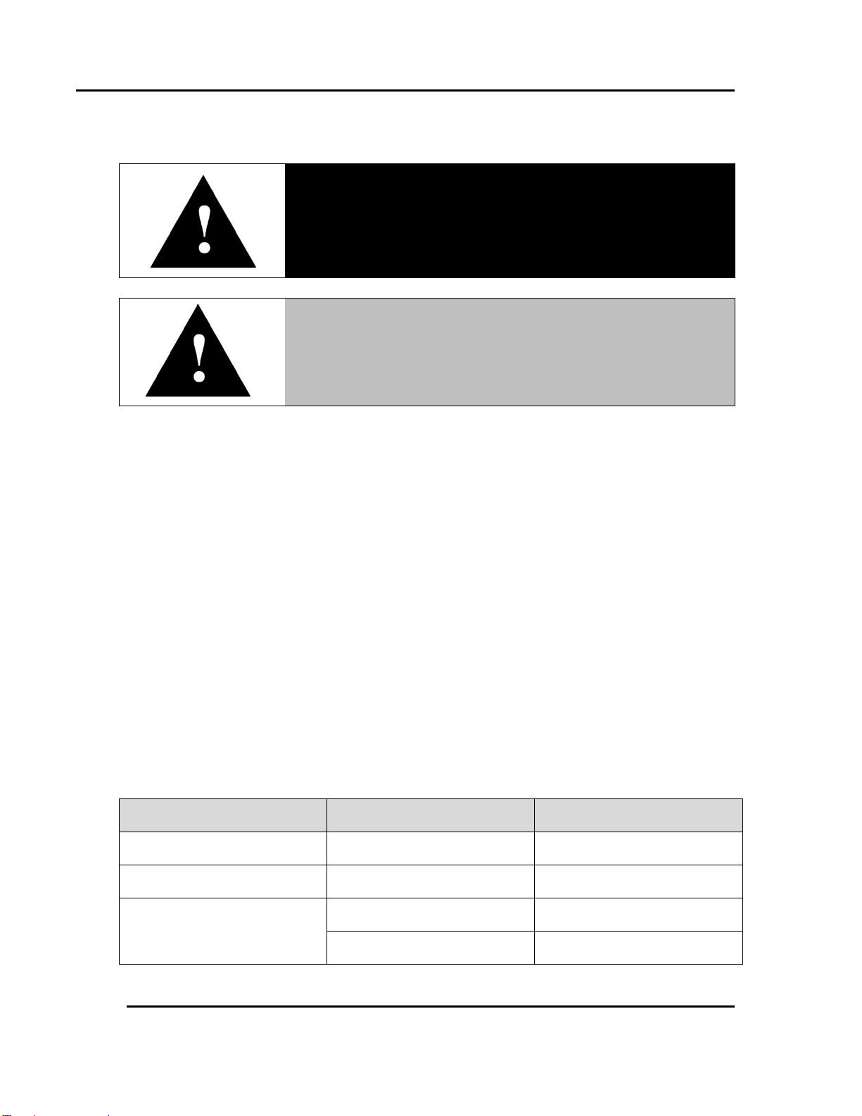
Danger!
Failure to heed warnings in this instruction manual and on the
oven could result in personal injury, property damage or death.
This icon signifies information that describes an unsafe
condition that may result in death, serious injury, or damage
to the equipment.
Danger!
Danger is the signal word used to indicate a hazardous
situation that, if not avoided, will result in death or severe
injury.
Warning!
Warning is the signal word used to indicate a hazardous
situation that, if not avoided, could result in death or severe
injury.
Caution!
Caution is the signal word used to indicate a hazardous
situation that, if not avoided, could result in moderate or
minor injury.
Notice
Notice is the signal word used to indicate a hazardous
situation that, if not avoided, could result in property damage.
This icon signifies supplemental important information.
LOG OUT
Bold, 10 point sans-serif typeface indicates a specific key or
button on screen to click.
8 Version 1.2
1.3. Organization of this Manual
This owner’s manual contains the most comprehensive set of information for the Despatch
Protocol 3™ controller, including installation instructions, theory of operation, operating
instructions, among other things.
1.4. Conventions
All rights reserved. No part of the contents of this manual may be reproduced, copied or transmitted in any form or by any
means including graphic, electronic, or mechanical methods or photocopying, recording, or information storage and
retrieval systems without the written permission of Despatch Industries, unless for purchaser's personal use.
Copyright © 2013 by Despatch Industries.
Page 9

Protocol 3 Controller Owner’s Manual ABOUT THIS MANUAL
Item
Description
Sampling Rate:
4 per second
Resolution:
16 bits. Always four times better than display resolution.
Impedance:
>10MΩresistive, except DC mA (5Ω) and V (47kΩ)
Temp Stability:
Error <0.01% of span per °C change in ambient temperature
Supply Variation:
Supply voltage influence negligible within supply limits
Humidity Influence:
Negligible if non‐condensing
Process Display:
Displays up to 5% over and 5% under span limits
Process Variable
Input Offset:
Reading adjustable ± Controller Span. Values added to
Process Variable, Values subtracted from Process Variable.
Sensor Break
Detection:
Thermocouple & RTD—SSR output goes to 0
High Limit Sensor Break alarms activate
Linear (4 to 20mA, 2 to 10V and 1 to 5V only)—SSR
output goes to 0
Isolation:
Isolated from all outputs (except SSR driver) at 240V AC
Supported
Thermocouple Types
& Ranges:
Type
Range °C
Range °F
B
+100 to 1824°C
+211 to 3315°F
C
0 to 2320°C
32 to 4208°F
D
0 to 2315°C
32 to 4199°F
E
-240 to 1000°C
‐400 to 1832°F
J
-200 to 1200°C
-328 to 2192°F *
K
‐200 to 1200°C
‐328 to 2192°F *
L
0 to 762°C
32 to 1402°F *
N
0 to 1399°C
32 to 2551°F *
PtRh
20%: 40%
0 to 1850°C
32 to 3362°F
R
0 to 1759°C
32 to 3198°F
Version 1.2 9
1.5. Specifications
Specifications for the Protocol 3 controller include six sets of information:
Process Input (Table 1)
Outputs (Table 2)
Operating Conditions (Table 3)
Conformance Norms (Table 4)
Display (Table 5)
Data Recorder (Table 6)
Table 1. Process Input.
All rights reserved. No part of the contents of this manual may be reproduced, copied or transmitted in any form or by any
means including graphic, electronic, or mechanical methods or photocopying, recording, or information storage and
retrieval systems without the written permission of Despatch Industries, unless for purchaser's personal use.
Copyright © 2013 by Despatch Industries.
Page 10

ABOUT THIS MANUAL Protocol 3 Controller Owner’s Manual
Item
Description
S
0 to 1762°C
32 to 3204°F
T
‐240 to 400°C
‐400 to 752°F *
Optional decimal place can be displayed up to 999.9°C/F
Thermocouple
Calibration:
±0.1% of full range, ±1LSD (±1°C for internal CJC if enabled).
Linearization better than better ±0.2°C (±0.05 typical) on
ranges marked * in the table above. Linearization for other
ranges is better than ±0.5°C. BS4937, NBS125 & IEC584.
Supported RTD Types
& Ranges:
Type
Range °C
Range °F
3‐Wire
PT100
‐199 to 800°C
‐328 to 1472°F
NI120
‐80 to 240°C
‐112 to 464°F
Optional decimal place can be displayed up to 999.9°C/F
RTD Calibration:
0.1% of full range, ±1LSD
Linearization:
Linearization better than ±0.2°C (±0.05 typical).
PT100 input to BS1904 & DIN43760 (0.00385Ω/Ω/°C).
RTD Excitation:
Sensor current 150μA ±10%
Lead Resistance:
<0.5% of span error for max 50Ωper lead, balanced
Supported Linear
Types & Ranges:
Type
Range
Offset Range
mA DC
0 to 20mA DC
4 to 20mA DC
mV DC
0 to 50mV DC
10 to 50mV DC
V DC
0 to 5V DC
1 to 5V DC
V DC
0 to 10V DC
2 to 10V DC
Scalable from ‐9999 to 10000. Decimal point selectable from 0
to 3 places, but limited to 5 display digits (e.g. 9999.9)
Maximum Overload:
1A on mA input terminals, 30V on voltage input terminals
DC Calibration:
±0.1% of full range, ±1LSD
DC Input Multi‐Point:
Linearization:
Up to 15 scaling values can be defined anywhere between 0.1
and 100% of input
Item
Description
Relays
Type & Rating:
Single pole single throw (SPST); 2A resistive at 120/240VAC
Lifetime:
>200,000 operations at rated voltage/current
Isolation:
Basic Isolation
10 Version 1.2
Table 2. Outputs.
All rights reserved. No part of the contents of this manual may be reproduced, copied or transmitted in any form or by any
means including graphic, electronic, or mechanical methods or photocopying, recording, or information storage and
retrieval systems without the written permission of Despatch Industries, unless for purchaser's personal use.
Copyright © 2013 by Despatch Industries.
Page 11

Protocol 3 Controller Owner’s Manual ABOUT THIS MANUAL
Item
Description
Linear DC
Resolution:
8 bits in 250mS (10 bits in 1s typical, >10 bits in >1s typical)
Accuracy:
±0.25% of range, (mA @ 250W, V @ 2kW). Degrades linearly
to ±0.5% for increasing burden (to specification limits)
Isolation:
Basic Isolation
Item
Description
Temperature:
Operating: 0°C to 55°C (32°F to 131°F)
Storage: –20°C to 80°C (-4°F to 176°F)
Relative Humidity:
20% to 95% non‐condensing
Supply Voltage and
Power:
100 to 240VAC ±10%, 50/60Hz, 20VA
Item
Description
EMI:
CE: Complies with EN61326
Safety Considerations:
CE: Complies with EN61010‐1. UL, cUL to UL61010C‐1.
Pollution Degree 2, Installation Category II
Front Panel Sealing:
IP65 rating. IP20 behind the panel. (IP rating not recognized /
approved by UL)
Front Panel Cleaning:
Wash with warm soapy water and dry immediately. Close the
USB cover (if fitted) before cleaning.
Item
Description
Display Type:
160 x 80 pixel, monochrome graphic LCD with a dual color
(red/green) backlight
Display Area:
66.54mm (W) x 37.42mm (H)
Display Characters:
0 to 9, a to z, A to Z, plus ( ) ‐ and _
Version 1.2 11
Table 3. Operating Conditions (For indoor use).
Table 4. Conformance Norms.
Table 5. Display.
All rights reserved. No part of the contents of this manual may be reproduced, copied or transmitted in any form or by any
means including graphic, electronic, or mechanical methods or photocopying, recording, or information storage and
retrieval systems without the written permission of Despatch Industries, unless for purchaser's personal use.
Copyright © 2013 by Despatch Industries.
Page 12

ABOUT THIS MANUAL Protocol 3 Controller Owner’s Manual
Item
Description
Recording Memory:
1Mb non‐volatile flash memory. Data retained when power is
turned off
Recording Interval:
1; 2; 5; 10; 15; 30 seconds or 1; 2; 5; 10; 15; 30 minutes
Recording Capacity:
Dependent on sample rate and number of values recorded.
Two values can be recorded for up to 7 days at 10s intervals.
More values or faster sample rates deduce the maximum
duration.
RTC Battery Type:
VARTA CR 1616 3V Lithium. Clock runs for >1 year without
power (Part # 274030)
RTC accuracy:
Real Time Clock error <1 second per day
12 Version 1.2
Table 6. Data Recorder.
All rights reserved. No part of the contents of this manual may be reproduced, copied or transmitted in any form or by any
means including graphic, electronic, or mechanical methods or photocopying, recording, or information storage and
retrieval systems without the written permission of Despatch Industries, unless for purchaser's personal use.
Copyright © 2013 by Despatch Industries.
Page 13

Protocol 3 Controller Owner’s Manual SAFETY
Danger!
Electrical panels contain high voltage. Disconnect and lock out the
power supply before working inside any electrical panels. Failure to
lock out the power supply will result in death or injury.
Version 1.2 13
2. Safety
2.1. Safety Information
Do not work on the Protocol 3 controller without reading and understanding this section which
contains important information and warnings. Ignoring these warnings can result in death, serious
injury or damage to the machine and product.
2.1.1. Lockout
Machine lockout places the Protocol 3 controller into a zero energy state and prevents accidental
machine start up. Always follow the Lockout Procedure described in this Section before cleaning,
maintaining or repairing the Protocol 3 controller. An accidental start-up, while working on the
Protocol 3 controller, can result in serious injury or death.
2.1.1.1. Lockout Requirements
1. Every power source that can energize any element of the Protocol 3 controller must be shut
off at the closest possible power source. This includes air, water, nitrogen and electricity,
including the Disconnect Switch.
2. After energy sources are locked out, test to ensure circuits are de-energized.
2.1.1.2. Lockout Procedure with Despatch Products
Personnel authorized to lockout equipment must have the necessary locks to perform the lockout.
1. Physically disconnect all electrical power to the machine or lockout (with a padlock) the
appropriate breaker or disconnects.
2. Close all valves and bleed off any pressure.
3. Test for power by attempting a start with the machine controls.
4. Identify the Lockout Condition with a tag on the electrical disconnect and pneumatic shut off
valves.
5. When work is complete, remove all tags and restore the machine to its working state.
2.2. Maintenance
Only qualified and trained personnel should perform maintenance or repair.
All rights reserved. No part of the contents of this manual may be reproduced, copied or transmitted in any form or by any
means including graphic, electronic, or mechanical methods or photocopying, recording, or information storage and
retrieval systems without the written permission of Despatch Industries, unless for purchaser's personal use.
Copyright © 2013 by Despatch Industries.
Page 14
SAFETY Protocol 3 Controller Owner’s Manual
Danger!
Contact with energized electrical sources will result in serious
injury or death.
Danger!
Always disconnect all power before extinguishing a fire.
Attempting to extinguish a fire in a machine connected to
electrical power will result in serious injury or death.
14 Version 1.2
2.3. Electrical Power
Only qualified and trained personnel should perform electrical maintenance or electrical repair.
Before performing maintenance, disconnect all electrical power from the machine. Use a
padlock and lockout all disconnects feeding power to the machine.
Never clean or repair the controller when in operation.
Unauthorized alterations or modifications to Protocol 3 controller are strictly forbidden.
Never modify any electrical circuits. Unauthorized modifications can impair the function and
safety of the Protocol 3 controller.
2.4. Fire
Keep the Protocol 3 controller clean and free of scrap materials, oil or solvents to prevent the
possibility of fire. In the event of fire, use a fire extinguisher as follows.
1. De-energize the machine immediately by pushing an Emergency Stop push button (if
supplied).
2. Turn off the remote main disconnect (customer supplied disconnect).
3. If the fire is in the workspace, keep the door closed.
4. Extinguish the fire.
2.5. Equipment Lockout Requirements
To prevent injury or equipment damage during inspection or repair, the Protocol 3
controller must be locked out.
All rights reserved. No part of the contents of this manual may be reproduced, copied or transmitted in any form or by any
means including graphic, electronic, or mechanical methods or photocopying, recording, or information storage and
retrieval systems without the written permission of Despatch Industries, unless for purchaser's personal use.
Copyright © 2013 by Despatch Industries.
Page 15
Protocol 3 Controller Owner’s Manual THEORY OF OPERATION
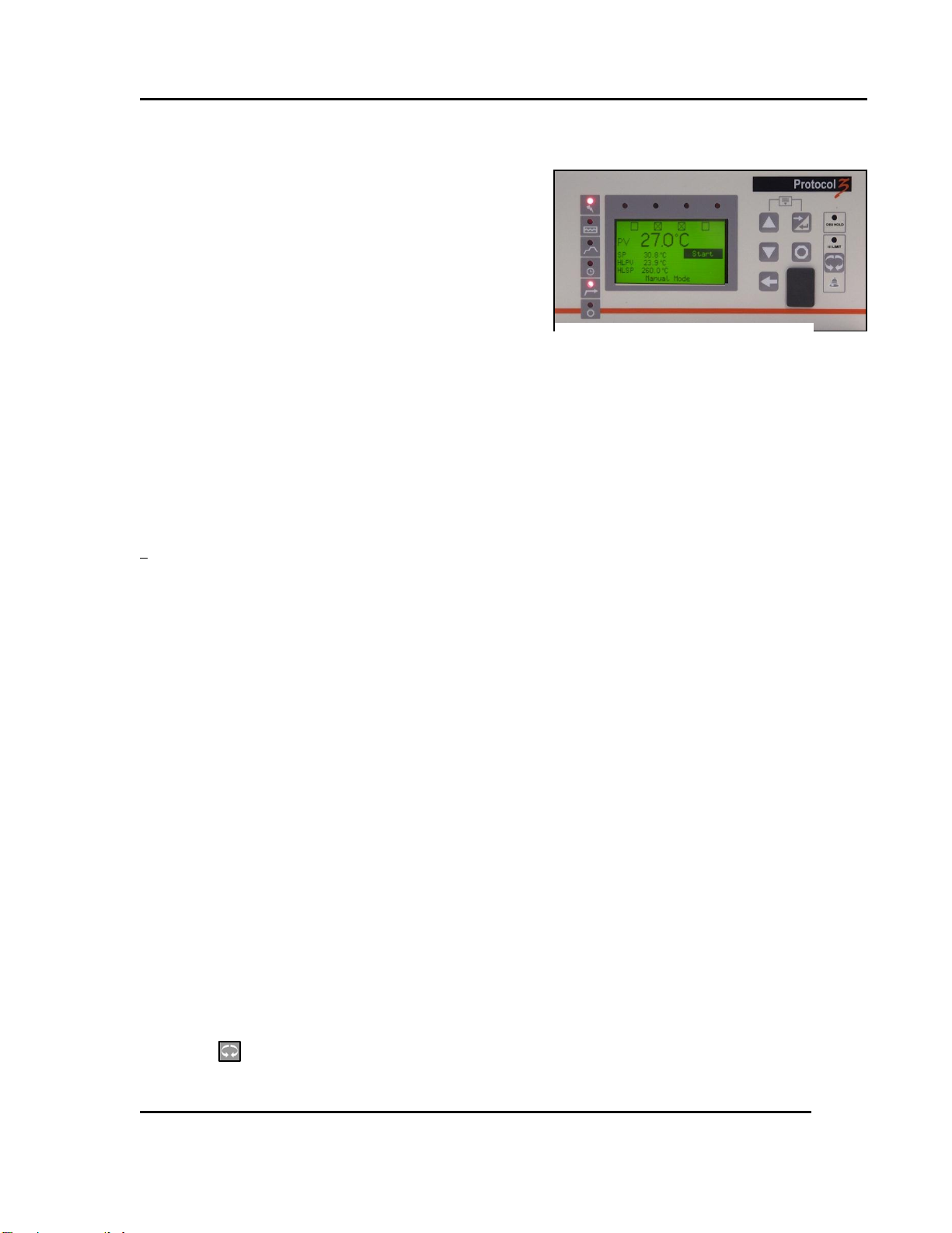
Figure 1. Operator Interface.
Version 1.2 15
3. Theory of Operation
The Protocol 3 is a microprocessor based digital
temperature controller designed for simple and flexible
oven operation (Figure 1). The Protocol 3 controller
operates as a dual-functioning controller/high limit
instrument. The control portion utilizes a
time-proportioning voltage signal to control heating
devices with minimal temperature fluctuations.
The high limit portion protects the product and/or the
oven from overheating. If the product being processed has a critical high temperature limit, the
high limit setpoint should be set to a temperature somewhat below the temperature at which the
product could be damaged. If the product does not have a critical high temperature limit, the high
limit setpoint should be set 5 to 15 degrees higher than the maximum programmed setpoint at
which the oven will operate.
The Protocol 3 controller provides three primary operating modes:
Manual: Oven operates continuously at a fixed temperature until turned off.
Timer: Oven operates at a fixed temperature for a user-selected time period, and then
automatically turns off.
Profile: Temperatures increase or decrease as defined by 255 segments that can be allocated
to 64 ramp and soak profiles. The profiles can be linked to provide additional temperature
combinations.
The Protocol 3 controlled is equipped to allow a ramp/soak temperature control, which maintains
oven temperature with either a fixed setpoint or a ramp/soak profile.
3.1. System Control—In General
The Protocol 3 controller provides outputs for the cooling fan, door lock switch/door release
pushbutton, and optional beacon light
A number of profiles for oven heating cycles are stored in the Protocol 3 controller. Access
profiles using the Protocol 3 keypad
The Protocol 3 controls the solenoid valves in an inert atmosphere oven for purge, maintain
and water cooling operation
The Protocol 3 can also be operated remotely with a PC running Protocol Manager software.
3.1.1. High-Limit Function
The Protocol 3 controller has an integrated high limit function which disables the heater output
when tripped. The High-Limit temperature is displayed as HLPV (Manual Mode only).
If the high limit trips, the Hi-Limit indicator will light and the relay must be manually reset.
Allow the oven to cool several degrees below the setpoint (or increase the high limit setpoint) and
then press . The indicator will turn off.
Copyright © 2013 by Despatch Industries.
All rights reserved. No part of the contents of this manual may be reproduced, copied or transmitted in any form or by any
means including graphic, electronic, or mechanical methods or photocopying, recording, or information storage and
retrieval systems without the written permission of Despatch Industries, unless for purchaser's personal use.
Page 16
THEORY OF OPERATION Protocol 3 Controller Owner’s Manual
16 Version 1.2
3.1.2. Outputs
The Protocol 3 controller comes standard with an output signal that can transmit temperature
data, setpoint data or control power to a user-supplied recording device. Output relays (five) can
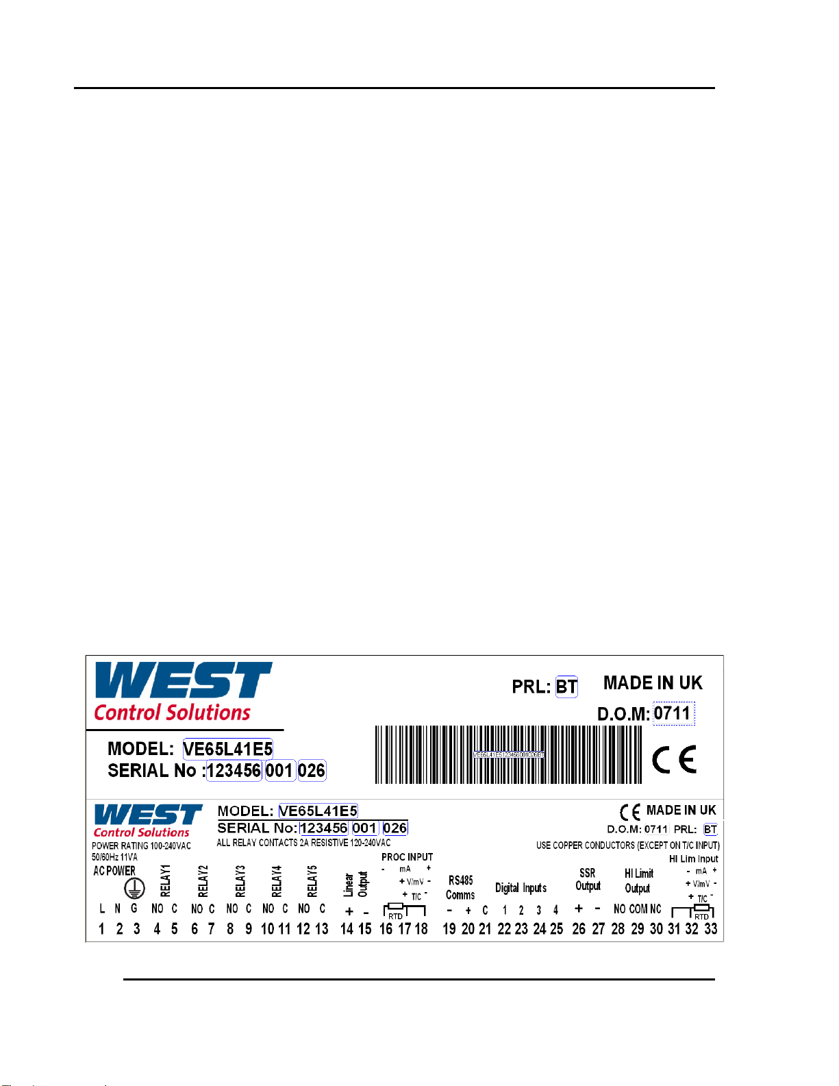
also signal user-specified events or alarm to external devices (Figure 2 and Figure 3).
Heating output: The control output is a DC voltage open-collector output which is
time-proportioned and designed to control a heat control device such as a solid state relay.
High limit: The high limit output is a SPDT relay which is energized under normal operating
conditions. If the control senses a temperature higher than the high limit setpoint, or if there is
a sensor error, the high limit relay will de-energize until the condition is cleared and Reset is
pressed. When the high limit relay is de-energized, the heater is disabled.
Retransmission: The retransmission output is a signal that is proportional to the process
temperature, setpoint or control power:
o 0-5V
o 0-10V
o 2-10V
o 020 ma
o 4-20 ma
o 0-10VDC Power Supply
The signal can be an input to other devices such as a chart recorder.
Relays: The five SPST dry contact relay outputs can be configured to function as alarms,
events, or end of cycle. These outputs can be utilized in Manual, Timer or Profile Modes.
3.2. Remote Communication
When used with a PC running Protocol Manager™ software, the Protocol 3 controller allows an
operator to remotely control the oven, download recipes and log data.
Copyright © 2013 by Despatch Industries.
All rights reserved. No part of the contents of this manual may be reproduced, copied or transmitted in any form or by any
means including graphic, electronic, or mechanical methods or photocopying, recording, or information storage and
retrieval systems without the written permission of Despatch Industries, unless for purchaser's personal use.
Page 17
Protocol 3 Controller Owner’s Manual THEORY OF OPERATION
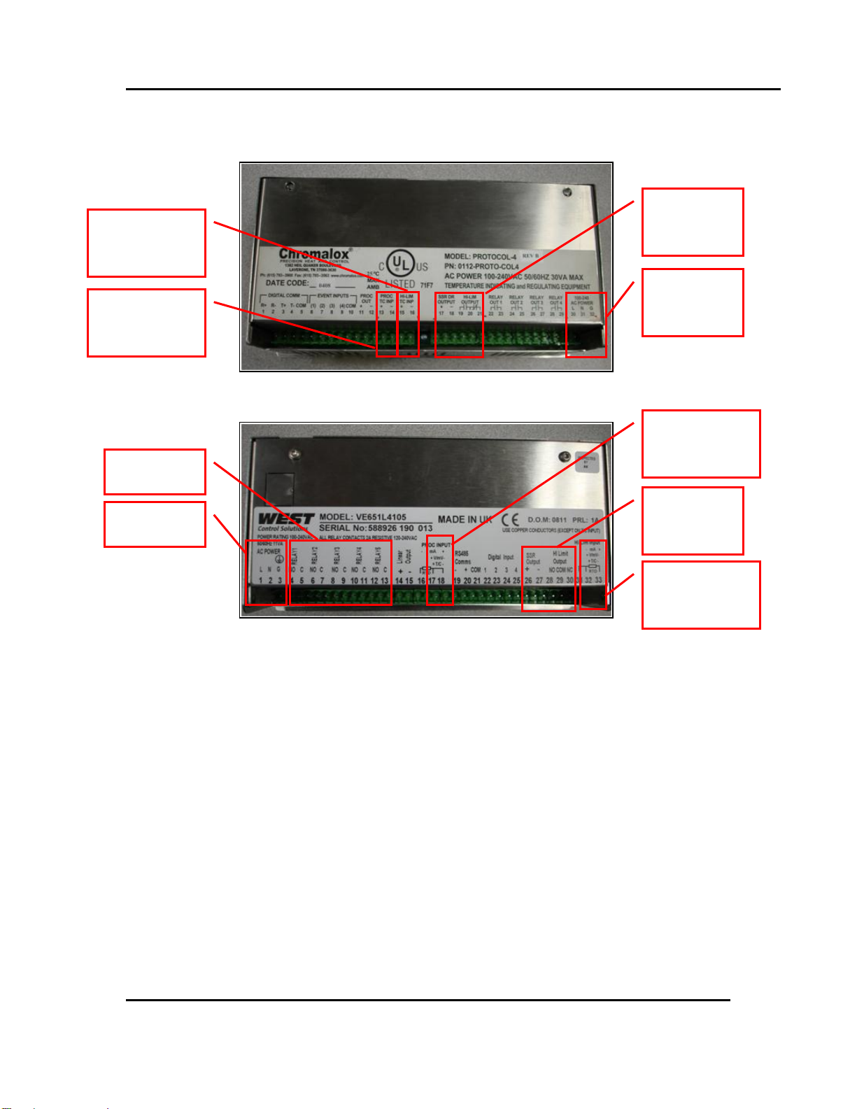
Protocol Plus Rear Panel
Protocol 3 Rear Panel
Former
Connections
New Power
Connections
Former SSR
Connections
New SSR
Connections
Former Control
Connections
Former Hi-limit
Connections
New Control
Connections
New Hi-limit
Connections
Relays
Figure 3. Protocol Plus to Protocol 3 Connection Conversions.
Figure 2. Typical Controller Output Sticker.
Version 1.2 17
and Hi-Limit
Thermocouple
Power
Thermocouple
Thermocouple
and Hi-Limit
Thermocouple
All rights reserved. No part of the contents of this manual may be reproduced, copied or transmitted in any form or by any
means including graphic, electronic, or mechanical methods or photocopying, recording, or information storage and
retrieval systems without the written permission of Despatch Industries, unless for purchaser's personal use.
Copyright © 2013 by Despatch Industries.
Page 18
ASSEMBLY & SETUP Protocol 3 Controller Owner’s Manual
Danger!
All grounding and safety equipment must be in compliance with
applicable codes, ordinances and accepted safe practices.
Terminal Block
Former
Protocol Plus Connections
New
Protocol 3 Connections
Three pin terminal block for
power leads
Terminals 30, 31, 32
Terminals 1, 2, 3
Five pin terminal block for
SSR and Hi-limit
Terminals 17, 18, 19, 20, 21
Terminals 26, 27, 28, 29, 30
Remove the four-pin terminal
block from thermocouples and
rewire with two three-pin
blocks.
Control Thermocouple
Terminals 13, 14
Control Thermocouple
Terminals 17, 18
Hi-limit Thermocouple
Terminals 15, 16
Hi-limit Thermocouple
Terminals 32, 33
Warning!
Disconnect the main power switch or power cord before
attempting any repair or adjustment.
18 Version 1.2
4. Assembly & Setup
4.1. Install the Protocol 3 Controller
When replacing a Protocol 3 controller, follow the steps below. Tools required for installation
include ¼” socket set with #1 bit, #2 Philips screwdriver.
1. Disconnect the power.
2. Unplug all terminals on the rear of the control, noting the proper connections (Figure 3).
3. Remove the retaining clips for the controller.
4. Remove the controller.
5. Insert the new controller into the panel.
6. Fasten the retaining clips.
7. Re-plug all terminals.
8. Secure the control panel.
4.2. Protocol 3 Controller Conversion with NO Options
To replace the older model Protocol Plus controller with the newer Protocol 3 controller, connect
terminal blocks as indicated in Table 7 and Figure 3.
Table 7. Protocol Plus to Protocol 3 Controller Conversion.
All rights reserved. No part of the contents of this manual may be reproduced, copied or transmitted in any form or by any
means including graphic, electronic, or mechanical methods or photocopying, recording, or information storage and
retrieval systems without the written permission of Despatch Industries, unless for purchaser's personal use.
Copyright © 2013 by Despatch Industries.
Page 19

Protocol 3 Controller Owner’s Manual ASSEMBLY & SETUP
Version 1.2 19
4.3. Setting Up Remote Communication
Remote communication between the Protocol 3 controller and a PC running the Despatch
Protocol Manager software involves providing each controller with a unique address and
following the communication protocol procedures. Up to 32 separate controllers can be run from
a PC running the Despatch Protocol Manager software. See the Protocol Manager Instruction
Manual for the complete set-up procedure.
All rights reserved. No part of the contents of this manual may be reproduced, copied or transmitted in any form or by any
Copyright © 2013 by Despatch Industries.
means including graphic, electronic, or mechanical methods or photocopying, recording, or information storage and
retrieval systems without the written permission of Despatch Industries, unless for purchaser's personal use.
Page 20
WORKING WITH OPERATING MODES Protocol 3 Controller Owner’s Manual
Users and operators of this controller must comply with
operating procedures and training of operating personnel as
required by the Occupational Safety and Health Act (OSHA) of
1970, Section 5 and relevant safety standards, and other safety
rules and regulations of state and local governments. Refer to
the relevant safety standards in OSHA and National Fire
Protection Association (NFPA), Section 86 of 1990.
Keypad
Button
Function
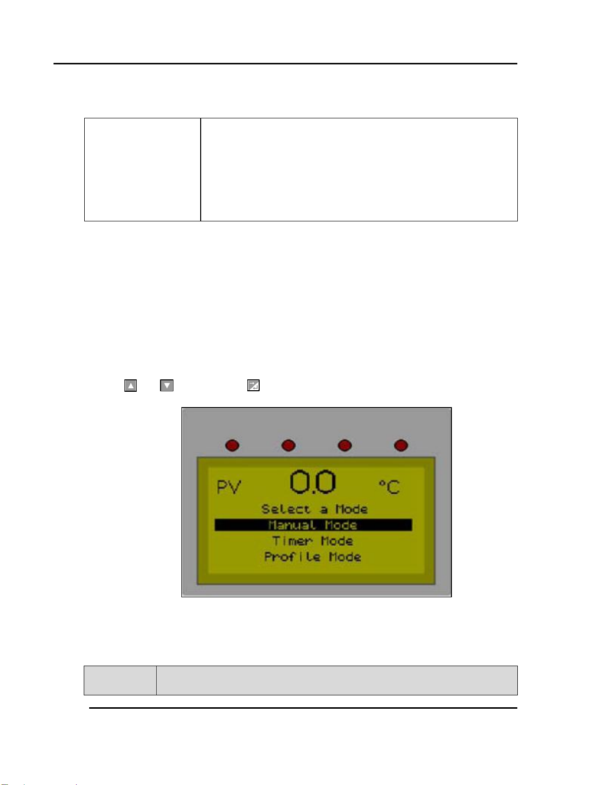
Figure 4. Select a Mode Display.
20 Version 1.2
5. Working with Operating Modes
5.1. User Controls
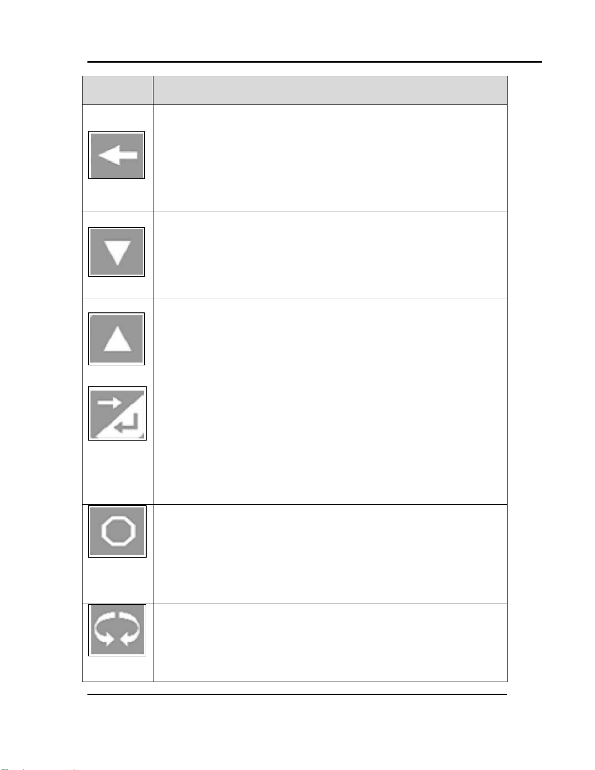
Each Protocol 3 Controller has six keypad switches (Table 8). Use the buttons to navigate user
menus, adjust parameter values and control outputs. In configuration screens, a context sensitive
scrolling help-text displays user-guides about the function of the keys across the bottom of the
screen.
The Protocol 3 Controller has nine LEDs which indicate a variety of instrument functions (Table
9).
When the Protocol 3 Controller is first powered ON, the screen displays Select a Mode (Figure
4). Use and to navigate and to select the highlighted mode.
Table 8. Keypad Buttons and Functions.
All rights reserved. No part of the contents of this manual may be reproduced, copied or transmitted in any form or by any
means including graphic, electronic, or mechanical methods or photocopying, recording, or information storage and
retrieval systems without the written permission of Despatch Industries, unless for purchaser's personal use.
Copyright © 2013 by Despatch Industries.
Page 21
Protocol 3 Controller Owner’s Manual WORKING WITH OPERATING MODES
Keypad
Button
Function
Navigate to previous screen
Press to move back to the previous parameter or screen in the current
mode.
NOTE: Pressing this switch updates the instrument to the value
displayed. If editing a parameter, ensure the current (highlighted)
parameter value is correct before pressing.
Navigate down through menu/parameter lists
Menus and configuration choice screens: Press to move to the next item on
the list.
Editable values: Press to decrease. Press and hold to speed the change.
Trend View: press to move the Cursor Line back through stored data
points.
Navigate up through menu/parameter lists
Menus and configuration choice screens: Press to move to the previous
item on the list.
Editable values: Press to increase. Press and hold to speed the change.
Trend View: press to move the Cursor Line forward through stored data
points.
Navigate to next item on a screen or to next screen
Press to move forward to the next parameter or screen in the current mode.
Enables Edit on parameters in the Main Mode selections.
NOTE: Pressing this switch updates the instrument to the value
displayed. If editing a parameter, ensure the current (highlighted)
parameter value is correct before pressing.
Manual, Timer and Profile Mode: press to stop current process
In Manual Mode, pressing switch disables the controlling output
In Timer Mode, pressing switch stops timer and disables controlling output
In Profile Mode, pressing switch stops current profile and disables
controlling output
Reset Latched High Limit relay if below alarm condition
If High Limit alarm is active, press to release the High Limit relay.
NOTE: This switch releases the High Limit relay only if the controller is
Version 1.2 21
All rights reserved. No part of the contents of this manual may be reproduced, copied or transmitted in any form or by any
means including graphic, electronic, or mechanical methods or photocopying, recording, or information storage and
retrieval systems without the written permission of Despatch Industries, unless for purchaser's personal use.
Copyright © 2013 by Despatch Industries.
Page 22

WORKING WITH OPERATING MODES Protocol 3 Controller Owner’s Manual
Keypad
Button
Function
not in the High Alarm State (LED indicator turned OFF).
and to move up one menu level:
Simultaneously press
From Select a Mode, pressing both moves to the main menu.
From Sub-menus, press both several times to reach the main menu.
NOTE: Simultaneously pressing these switches updates the instrument to
the value displayed. If editing a parameter, ensure the current
(highlighted) parameter value is correct before pressing.
LED
Function
Power LED: When lit, indicates power to the device.
Heater LED: When lit, indicates primary heating output is active.
Profile LED: When lit, indicates a profile is currently running.
Timer LED: When lit, indicates a timer is currently running.
Manual LED: When lit, indicates the controller is in Manual Mode.
22 Version 1.2
Table 9. LEDs and Functions.
All rights reserved. No part of the contents of this manual may be reproduced, copied or transmitted in any form or by any
means including graphic, electronic, or mechanical methods or photocopying, recording, or information storage and
retrieval systems without the written permission of Despatch Industries, unless for purchaser's personal use.
Copyright © 2013 by Despatch Industries.
Page 23

Protocol 3 Controller Owner’s Manual WORKING WITH OPERATING MODES
LED
Function
Cycle Complete LED: When lit, indicates the controller is currently stopped.
When lit during a profile or Timer Mode, indicates process value has deviated
from the soak value indicated by the controller. Set Soak Deviation value in the
Profile Configuration mode or in the Timer Mode from the Main Menu. See
Troubleshooting Section 7 for more information.
When lit indicates the controller has exceeded the High Limit Value. Set High
Limit Alarm Value and Hysteresis in the Alarm Configuration menu.
(Four LEDs
located above
LCD display)
When lit, indicates relays 1-4 are active. Relay can be assigned as an Event,
Alarm or Cycle.
Change configuration controls depending on the mode used.
Refer to the specific operating instructions below, for more
information.
Regularly backup critical system data according to your
company policies. Be sure to back up configuration and profiles
to a removable memory device. Refer to Section 5.5.1 for more
information.
Version 1.2 23
5.2. First Screens
At initial power-up, control is in Select a Mode. This screen allows the choice of manual mode,
timer mode or profile mode.
All rights reserved. No part of the contents of this manual may be reproduced, copied or transmitted in any form or by any
means including graphic, electronic, or mechanical methods or photocopying, recording, or information storage and
retrieval systems without the written permission of Despatch Industries, unless for purchaser's personal use.
Copyright © 2013 by Despatch Industries.
Page 24

WORKING WITH OPERATING MODES Protocol 3 Controller Owner’s Manual
Four relay LEDs
Relay navigational boxes
Figure 5. Manual Mode Display Screen.
24 Version 1.2
5.2.1. Manual Mode
Manual Mode allows the oven to operate continuously at a fixed temperature until turned off. Use
Manual Mode (Figure 5) to control Set Point, High Limit Value and four relays.
Better explanation:
5.2.1.1. Display Manual Mode
From the Select a Mode screen, press or to navigate to Manual Mode. Press to select
the highlighted option. Press to exit from Manual Mode and to stop all outputs.
5.2.1.2. Start Manual Mode
1. Navigate to and highlight Manual Mode.
2. Press to display the Manual Mode screen.
3. Manual Mode allows you to set the setpoint (SP), and the High Limit set point (HLSP).
a. Press or to navigate through the menu.
b. Select and highlight the menu item.
c. Press .
d. Press or to change values.
e. Press to select the value.
4. Manual Mode allows you to set event relay status
a. Press or to navigate to and select the appropriate relay (Figure 5).
b. Press to toggle the relay on and off.
5. Once all parameters are set, press or to navigate to and highlight Start.
6. Press to start the process.
a. Press to abort the process.
All rights reserved. No part of the contents of this manual may be reproduced, copied or transmitted in any form or by any
means including graphic, electronic, or mechanical methods or photocopying, recording, or information storage and
retrieval systems without the written permission of Despatch Industries, unless for purchaser's personal use.
Copyright © 2013 by Despatch Industries.
Page 25

Protocol 3 Controller Owner’s Manual WORKING WITH OPERATING MODES
Hours
Seconds
Figure 6. Timer Mode Display Screen.
Version 1.2 25
b. After pressing , press to return to Select a Mode screen
7. Adjust the temperature setpoint while running in Manual or Timer Mode by:
a. Press .
b. Press or to select mode of operation.
c. Press .
d. Press or to change the SP value.
e. Press .
f. Press to return to normal display.
8. Return to Stopped Mode at any time, press and the Cycle Complete LED will illuminate
Press to select a mode screen.
5.2.2. Timer Mode
Use Timer Mode to control Time Set Point: when
the time expires, the control output is turned OFF
(Figure 6).
1. Navigate to and highlight Timer Mode.
2. Press or to navigate to the desired
time or temperature units.
3. Press to select the value to change.
4. Press or to change value.
5. Press to enter the desired value.
6. Timer Mode allows you to set event relay status:
a. Press or to navigate to and select
the appropriate relay (Figure 5).
b. Press to toggle the relay ON and OFF.
7. Set all parameters then press or to navigate to and highlight Start.
8. Press to start the process.
a. Press to abort the process
b. Press to return to Select a Mode screen.
9. Adjust the temperature setpoint while running in Manual Mode or Timer Mode by:
a. Press .
All rights reserved. No part of the contents of this manual may be reproduced, copied or transmitted in any form or by any
means including graphic, electronic, or mechanical methods or photocopying, recording, or information storage and
retrieval systems without the written permission of Despatch Industries, unless for purchaser's personal use.
Copyright © 2013 by Despatch Industries.
Page 26

WORKING WITH OPERATING MODES Protocol 3 Controller Owner’s Manual
26 Version 1.2
b. Press or to navigate to the desired time or temperature units.
c. Press .
d. Press or to change the SP value.
e. Press .
f. Press to return to normal display.
10. To return to Stopped Mode at any time, press and the Cycle Complete LED will
illuminate.
11. Press to return to Select A Mode screen.
5.2.3. Profile Mode
Navigate to HLSP to set the High Limit Setpoint before running a profile. Use Profile Mode to
select and run profiles that are programmed into the unit (Figure 7). Press or to
navigate, to select the highlighted profile. Press to start profile. Press to stop the
profile and to exit Profile Mode (profile must be stopped to exit Profile Mode).
All rights reserved. No part of the contents of this manual may be reproduced, copied or transmitted in any form or by any
Copyright © 2013 by Despatch Industries.
means including graphic, electronic, or mechanical methods or photocopying, recording, or information storage and
retrieval systems without the written permission of Despatch Industries, unless for purchaser's personal use.
Page 27

Protocol 3 Controller Owner’s Manual WORKING WITH OPERATING MODES
Status bar shows status of profile and segment.
If you are unable to select a desired profile, verify that Remote
Profile Control is Disabled. When Remote Profile Control is
Disabled, the Select Profile to Start reads “Digital”
Figure 7. Profile Mode.
Version 1.2 27
5.2.4. Main Menu
The Main Menu (Figure 8) provides access to a number of useful sub menus (Table 10). Access
the Main Menu from the Select a Mode screen (Figure 4) by:
1. Simultaneously press and .
2. Press or to navigate, to select the highlighted option.
3. Press to enter that mode.
All rights reserved. No part of the contents of this manual may be reproduced, copied or transmitted in any form or by any
means including graphic, electronic, or mechanical methods or photocopying, recording, or information storage and
retrieval systems without the written permission of Despatch Industries, unless for purchaser's personal use.
Copyright © 2013 by Despatch Industries.
Page 28

WORKING WITH OPERATING MODES Protocol 3 Controller Owner’s Manual
Menu Item
Description
Mode Selection
Return to Select a Mode screen
Timer Mode
See Timer Mode Option (Section 5.2.2)
Profile Setup
Create, edit and delete profiles
Recorder Control
Start, stop and delete recordings on unit.
USB Menu
Access all read/write options to USB device
Configuration Menu
Program all input and output settings
Automatic Tuning
Opens selection for Auto and Self Tune features
Product Information
Display information about unit
Service Information
Display name and address of service department
Figure 8. Main Menu.
28 Version 1.2
Table 10. Sub Menu Descriptions
Copyright © 2013 by Despatch Industries.
All rights reserved. No part of the contents of this manual may be reproduced, copied or transmitted in any form or by any
means including graphic, electronic, or mechanical methods or photocopying, recording, or information storage and
retrieval systems without the written permission of Despatch Industries, unless for purchaser's personal use.
Page 29

Protocol 3 Controller Owner’s Manual WORKING WITH OPERATING MODES
Regularly backup critical system data according to your
company policies. Be sure to back up configuration and profiles
to a removable memory device. Refer to Section 5.5.1 for more
information.
Find General Configuration Parameters in Section 5.6. Find
Profile Setup in Section 5.3
Note that other options are not visible until a profile is created.
Figure 9. Profile Setup.
Version 1.2 29
5.3. Setting up a Profile
Use Profile Setup to create, edit and delete profiles (Figure 9). Access the Profile Setup from the
Main Menu screen. The Profiler option allows storage of up to 255 profile segments, shared
between a maximum of 64 Profiles. Each profile controls the value of the setpoint over time;
increasing, decreasing or holding its value as required. See Table 11 for Profile Setup options.
Figure 10 (Table 12) shows the Protocol 3 Controller configuration options. Table 13 shows the
full list of Profile Parameter options.
All rights reserved. No part of the contents of this manual may be reproduced, copied or transmitted in any form or by any
means including graphic, electronic, or mechanical methods or photocopying, recording, or information storage and
retrieval systems without the written permission of Despatch Industries, unless for purchaser's personal use.
Copyright © 2013 by Despatch Industries.
Page 30

WORKING WITH OPERATING MODES Protocol 3 Controller Owner’s Manual
Menu Item
Description
General Configuration
Enable remote Profile control and Profile automatic start
Create a Profile
Create profile
Edit a Profile Header
Change the name of any created profile
Edit a Profile Segment
Change the settings of a specific segment in a profile
Insert a Segment
Create a new segment in an existing profile
Delete a Segment
Delete a segment in an existing profile
Delete a Profile
Delete an existing profile
Delete all Profiles
Delete all profiles in the unit
30 Version 1.2
Table 11. Profile Setup Options.
All rights reserved. No part of the contents of this manual may be reproduced, copied or transmitted in any form or by any
means including graphic, electronic, or mechanical methods or photocopying, recording, or information storage and
retrieval systems without the written permission of Despatch Industries, unless for purchaser's personal use.
Copyright © 2013 by Despatch Industries.
Page 31

Protocol 3 Controller Owner’s Manual WORKING WITH OPERATING MODES
Figure 10. Profile Setup Menu.
Version 1.2 31
All rights reserved. No part of the contents of this manual may be reproduced, copied or transmitted in any form or by any
means including graphic, electronic, or mechanical methods or photocopying, recording, or information storage and
retrieval systems without the written permission of Despatch Industries, unless for purchaser's personal use.
Copyright © 2013 by Despatch Industries.
Page 32

WORKING WITH OPERATING MODES Protocol 3 Controller Owner’s Manual
Step #
Protocol 3 Descriptor
Option
Description
General Configuration
1.
Remote Profile Control
Disabled
Disallow a remote source to run a profile
Enabled
Allow a remote source to run a profile
2.
Automatic Start
Disabled
Disallow use of delayed start time
Enabled
Allow controller to start at a later time with
programmed delay
Create a Profile
3.
Enter a Profile Name
Unique name for each profile using up to 8
characters
4.
Profile Start Trigger
None
Profile start not delayed
After Delay
Set hours and minutes to delay before
starting the profile
Day and Time
Set time of day (hour and minutes) and day
of week to start profile. Options include
each day of the week and combinations of
days.
5.
Profile Recovery
Method
If power-down occurs while this profile is
running, specify the action for the controller
to take during power-up:
Control Off
Controller goes to OFF
Restart Profile
Controller restarts current profile
Maintain Last
Profile SP
Controller maintains previous profile
setpoint
Continue
Profile
Controller continues (for specified time) the
profile from where it was when power
failed.
Profile Abort Action
If program aborts, profile should:
Control Off
Controller goes off
6.
Maintain Last
Profile SP
Choose the number of times to cycle the
program, up to an infinite number of times.
Edit a Profile Segment
7.
Edit Segment Number
Ramp Time
Set target setpoint (degrees centigrade)
Set the segment ramp time (hh:mm:ss)
Set the Auto-Hold Type: None, Above
Setpoint, Below Setpoint, Band.
Set Events 1-5: Press or to
toggle between Active and Inactive.
8.
Ramp Rate
Set the target setpoint (degrees
centigrade)
Set the segment ramp rate in units per
hour
Set the Auto-Hold Type: None, Above
Setpoint, Below Setpoint, Band.
Set Events 1-5: Press or to
toggle between Active and Inactive.
9.
Step
Set the target setpoint (degrees centigrade)
10.
Dwell
Choose time to dwell at setpoint.
Specify Auto-Hold type: None, Above
setpoint, Below setpoint, Band
32 Version 1.2
Table 12. Profile Setup Steps, Options and Descriptions.
All rights reserved. No part of the contents of this manual may be reproduced, copied or transmitted in any form or by any
means including graphic, electronic, or mechanical methods or photocopying, recording, or information storage and
retrieval systems without the written permission of Despatch Industries, unless for purchaser's personal use.
Copyright © 2013 by Despatch Industries.
Page 33

Protocol 3 Controller Owner’s Manual WORKING WITH OPERATING MODES
Step #
Protocol 3 Descriptor
Option
Description
Set Events 1-5: Press or to
toggle between Active and Inactive
11.
Hold
Choose when to release Hold: Operator
Key Press or Time of Day
Set Events 1-5: Press or to
toggle between Active and Inactive
12.
Loop
Set the number of times to loop current
segment
Specify how to move back to the host
segment after specified loops: Ramp
time, hold
Set Events 1-5: Press or to
toggle between Active and Inactive
13.
Join
Joins one profile to another: specified
profile immediately follows first profile
Navigate to and highlight to select from
among the current profiles
Set Events 1-5: Press or to
toggle between Active and Inactive
14.
End
Ends the segment and creates the profile.
Choose segment type from: Control Off,
Maintain Last Profile SP, Control Off with
Events
15.
Repeat
Sequence
Then End
Repeats sequence specified number of
times and then ends the segment and
creates the profile. Along with enter
numbering of times to repeat sequence,
choose from: Control Off, Maintain Last
Profile SP, Control Off with Events
Version 1.2 33
5.3.1. Prepare for Profile Setup
From the Select a Mode screen, simultaneously press and to display the Main Menu
(Figure 8):
1. Navigate to and highlight Profile Setup.
2. Press to display Profile Setup Enter Profiler Mode Unlock Code screen.
3. Press to enter Unlock Code 0010.
4. Press to display the Profile Setup screen.
5. Press to move right and to move left. Press or navigate through
numbers, uppercase letters and lower case letters.
6. After entering the profile name, press as often as necessary to move to the next
screen.
All rights reserved. No part of the contents of this manual may be reproduced, copied or transmitted in any form or by any
means including graphic, electronic, or mechanical methods or photocopying, recording, or information storage and
retrieval systems without the written permission of Despatch Industries, unless for purchaser's personal use.
Copyright © 2013 by Despatch Industries.
Page 34

WORKING WITH OPERATING MODES Protocol 3 Controller Owner’s Manual
Before initiating the Profile Setup, use the programming
worksheet (Section 8.3) to work out all parameters. Once the
Profile Setup is begun, setup must continue to the end or lose
all entered values.
When programming an oven with a gas-fired heater, note that
the burner can be started manually or by programming a profile
using the Protocol 3 controller.
34 Version 1.2
Table 12 will serve as a useful guide for both general configuration and setting up a profile.
All rights reserved. No part of the contents of this manual may be reproduced, copied or transmitted in any form or by any
means including graphic, electronic, or mechanical methods or photocopying, recording, or information storage and
retrieval systems without the written permission of Despatch Industries, unless for purchaser's personal use.
Copyright © 2013 by Despatch Industries.
Page 35

Protocol 3 Controller Owner’s Manual WORKING WITH OPERATING MODES
Figure 11. Sample Profile.
Version 1.2 35
5.3.2. Sample Profile
Figure 11shows a graphic representation of the sample profile, while Figure 12 shows the
parameters entered to achieve that profile. Section 5.3.3 shows how to enter the profile.
All rights reserved. No part of the contents of this manual may be reproduced, copied or transmitted in any form or by any
means including graphic, electronic, or mechanical methods or photocopying, recording, or information storage and
retrieval systems without the written permission of Despatch Industries, unless for purchaser's personal use.
Copyright © 2013 by Despatch Industries.
Page 36

WORKING WITH OPERATING MODES Protocol 3 Controller Owner’s Manual
Figure 12. Sample Profile Values.
36 Version 1.2
All rights reserved. No part of the contents of this manual may be reproduced, copied or transmitted in any form or by any
means including graphic, electronic, or mechanical methods or photocopying, recording, or information storage and
retrieval systems without the written permission of Despatch Industries, unless for purchaser's personal use.
Copyright © 2013 by Despatch Industries.
Page 37

Protocol 3 Controller Owner’s Manual WORKING WITH OPERATING MODES
Version 1.2 37
5.3.3. Key In the Sample Profile Setup
To help show the process of setting up a profile, this section uses the sample profile as an
example (from Figure 11 and Figure 12). Figure 10 shows the overall flowchart for working with
Profile Setup. For entering sample values, we choose the default values.
Navigate to and Enter Profile Setup
From Select a Mode screen, simultaneously press and to display the Main Menu:
1. Navigate to and highlight Profile Setup.
2. Press to display Profile Setup Enter Profiler Mode Unlock Code screen.
3. Press to enter Factory Unlock Code 0010.
4. Press to display the Profile Setup screen.
5. Press to select Create a Profile.
6. Press to enter mode.
7. Input unique Profile name: press to move right and to move left. Press or
to navigate through numbers, uppercase letters and lower case letters.
8. After entering the profile name, press as often as necessary to move to the next
screen.
9. For Profile Start Trigger, when None is highlighted, press to complete the entry.
10. For Profile Recovery Method, when Control Off is highlighted, press to
complete the entry.
11. For Profile Abort Action, when Control Off is highlighted, press to complete the
entry.
12. For How Many Time to Cycle Program, press and navigate to the desired
number of cycles.
a. Press to complete the entry.
Program Segment 1 according the Sample Profile (Figure 11 and Figure 12):
13. When Segment Number 1 displays, press .
14. Highlight Ramp Time and press .
15. For Target Setpoint,
a. Press or navigate to 100°C (212°F).
b. Press to complete the entry.
16. For Segment Ramp Time,
a. Press or navigate to 1 hour (01:00:00).
Copyright © 2013 by Despatch Industries.
All rights reserved. No part of the contents of this manual may be reproduced, copied or transmitted in any form or by any
means including graphic, electronic, or mechanical methods or photocopying, recording, or information storage and
retrieval systems without the written permission of Despatch Industries, unless for purchaser's personal use.
Page 38

WORKING WITH OPERATING MODES Protocol 3 Controller Owner’s Manual
Note: Last segment must be an End segment to exit Profile Entry
Mode.
38 Version 1.2
b. Press as needed to complete the entry.
17. For Auto-Hold Type, when None is highlighted, press to complete the entry.
18. For Event 1-5, press as needed to accept Inactive.
Program Segment 2 according the Sample Profile:
19. When Segment Number 2 displays, press .
20. Highlight Dwell and press .
21. For Dwell at 100.0°C (212 °F),
a. Press or navigate to 1 hour (01:00:00).
b. Press as needed to complete the entry.
22. For Auto-Hold Type, when None is highlighted, press to complete the entry.
23. For Event 1-5, press as needed to accept Inactive.
Program Segment 3 according the Sample Profile:
24. When Segment Number 3 displays, press .
25. Highlight Ramp Time and press .
26. For Target Setpoint,
a. Press or navigate to 20°C (68°F).
b. Press to complete the entry.
27. For Segment Ramp Time,
a. Press or navigate to 2 hours (02:00:00).
b. Press as needed to complete the entry.
28. For Auto-Hold Type, when None is highlighted, press to complete the entry.
29. For Event 1-5, press as needed to accept Inactive.
Finish Profile Creation:
30. When Segment Number 4 displays, press .
31. Highlight End and press .
All rights reserved. No part of the contents of this manual may be reproduced, copied or transmitted in any form or by any
means including graphic, electronic, or mechanical methods or photocopying, recording, or information storage and
retrieval systems without the written permission of Despatch Industries, unless for purchaser's personal use.
Copyright © 2013 by Despatch Industries.
Page 39

Protocol 3 Controller Owner’s Manual WORKING WITH OPERATING MODES
Profile Parameter
Options
Profile Limits
Number of profiles = 64 maximum.
Total number of segments (all programs) = 255 maximum.
Loop Back Segments
1 to 9999 loops back to specified segment.
Profile Cycling
1 to 9999 or Infinite repeats per profile.
Sequence Repeats
1 to 9999 or Infinite repeats of joined profile sequences.
Segment Types
Ramp Up/Down over time, Ramp Rate Up/Down, Step, Dwell, Hold,
Join A Profile, End or Repeat Sequence Then End.
Time-base
All times specified in hh:mm:ss (Hours, Minutes & Seconds).
Segment Time
Maximum segment time 99:59:59 hh:mm:ss. Use loop-back for
longer segments (e.g. 24:00:00 x 100 loops = 100 days).
Ramp Rate
0.001 to 9999.9 display units per hour.
Hold Segment
Release
Release With Key-press, At Time Of Day or via a Digital Input.
Start From Value
1st segment starts from current setpoint or current PV input value.
Delayed Start
After 0 to 99:59 (hh:mm) time delay, or at specified day(s) & time.
Note: Enable Automatic Start in the Profile Setup: General
Configuration Menu. Delayed start will not operate unless
Automatic Start has been enabled.
Profile End Action
Selectable from: Control Off, Maintain Last Profile SP, Control
Off with Events. Use Controller Setpoint or Control Outputs Off.
Profile Abort Action
Selectable from: Keep Last Profile Setpoint, Use Controller Setpoint
or Control Outputs Off.
Power/signal Loss
Recovery Action
Selectable from: Continue Profile, Restart Profile, Keep Last Profile
Setpoint, Use Controller Setpoint or Control Outputs Off.
Auto-Hold
Off or Hold if input >Band above and/or below SP for each
segment.
Profile Control
Run, Manual Hold/Release, Abort or jump to next segment.
Profile Timing
Accuracy
0.02% Basic Profile Timing Accuracy.
± <0.5 second per Loop, End or Join segment.
Segment Events
Events turn on for the duration of the segment. For End Segments,
the event state persists until another profile starts, the user exits
from profiler mode, or the unit is powered down.
Version 1.2 39
a. For Segment End Type, with Control Off highlighted, press .
32. For Profile Created, press .
33. Press and to display the Main Menu. Press or to select Mode Selection
and press .
Table 13. Profile Parameter Options.
All rights reserved. No part of the contents of this manual may be reproduced, copied or transmitted in any form or by any
means including graphic, electronic, or mechanical methods or photocopying, recording, or information storage and
retrieval systems without the written permission of Despatch Industries, unless for purchaser's personal use.
Copyright © 2013 by Despatch Industries.
Page 40

WORKING WITH OPERATING MODES Protocol 3 Controller Owner’s Manual
Figure 13. Recorder Control.
Figure 14. Recorder Status.
All recordings in the unit can be downloaded to a USB device
using the USB port and the USB Menu.
40 Version 1.2
5.4. Recorder Control
Use Recorder Control to start, stop and clear
recordings (Figure 13). Access the Recorder
Control from the Main Manu.
1. Navigate to and highlight Recorder
Control.
2. Press to display Recorder Control
Enter Data Recorder Unlock Code screen.
3. Press as necessary to enter Factory
Unlock Code 0010.
4. Press to display the Start/Stop Data
Recording screen.
5. Press or to highlight and press to Stop Recording or Start Recording.
The Recorder Status screen (Figure 14) displays
after selecting an option.
Clear a recording while in Recorder Status screen
by pressing to advance to the Clear
Recordings screen.
All rights reserved. No part of the contents of this manual may be reproduced, copied or transmitted in any form or by any
means including graphic, electronic, or mechanical methods or photocopying, recording, or information storage and
retrieval systems without the written permission of Despatch Industries, unless for purchaser's personal use.
Copyright © 2013 by Despatch Industries.
Page 41

Protocol 3 Controller Owner’s Manual WORKING WITH OPERATING MODES
Regularly backup critical system data according to your
company policies. Be sure to back up configuration and profiles
to a removable memory device. Refer to Section 5.5.1 for more
information.
Note that a memory stick must be in place before the USB Menu
will display.
Figure 15. USB Menu.
Version 1.2 41
5.5. USB Menu
Use USB Menu to perform read/write options for USB devices connected to the unit using the
front USB port (Figure 15). Access the USB Menu from the Main Menu. See Table 14 for USB
Menus options.
1. Navigate to and highlight USB Menu.
2. Press to display Mode Unlock Code screen.
3. Press as necessary to enter Factory Unlock Code 0010.
4. Press to display the USB Menu screen.
All rights reserved. No part of the contents of this manual may be reproduced, copied or transmitted in any form or by any
means including graphic, electronic, or mechanical methods or photocopying, recording, or information storage and
retrieval systems without the written permission of Despatch Industries, unless for purchaser's personal use.
Copyright © 2013 by Despatch Industries.
Page 42

WORKING WITH OPERATING MODES Protocol 3 Controller Owner’s Manual
Menu Item
Description
Write Recorder Log File
Writes recorder Log data to USB
Read Profile File
Read profile from USB device to unit
Write Profile File
Write profile from unit to USB device
Read Configuration File
Read configuration file from USB device to unit
Write Configuration File
Write configuration file from unit to USB device
The Protocol 3 controller continues to control operations when
initializing the USB memory stick. Allow time for initializing to
complete before beginning new tasks.
42 Version 1.2
Table 14. USB Menu Options.
All rights reserved. No part of the contents of this manual may be reproduced, copied or transmitted in any form or by any
means including graphic, electronic, or mechanical methods or photocopying, recording, or information storage and
retrieval systems without the written permission of Despatch Industries, unless for purchaser's personal use.
Copyright © 2013 by Despatch Industries.
Page 43

Protocol 3 Controller Owner’s Manual WORKING WITH OPERATING MODES
Files must be located in these folders to be used by the controller.
When preparing to upload files from your PC, ensure that you save
them to the correct folder on the memory stick.
Note: to speed up the disk operation, keep the number of files
stored in these folders to a minimum.
If the file or folder named already exists, data will be overwritten.
Do not remove the memory stick from the USB port while a data
transfer operation is in progress. Data loss or corruption may
result.
Figure 17. USB Files and Folders Requirements (as
seen from Windows Explorer).
Figure 16. USB Port on Front Panel.
Version 1.2 43
5.5.1. Working with USB Memory Stick Folders and Files
Insert a memory stick into the port on the
front panel (Figure 16). The Protocol 3
performs an initialization process that finds
and/or creates folders on the memory stick
(Figure 17):
DEVICE: This folder must be located in
the Root of the USB memory stick
CONFIG: Configuration files (*.bct)
PROFILE: Profile program files (*.pfl)
RECORDER: Recorder log folders and
files. The user is asked for a new
recorder subfolder name before
transferring recorder data to USB. The
log files (*.csv) are placed in this folder.
All rights reserved. No part of the contents of this manual may be reproduced, copied or transmitted in any form or by any
means including graphic, electronic, or mechanical methods or photocopying, recording, or information storage and
retrieval systems without the written permission of Despatch Industries, unless for purchaser's personal use.
Copyright © 2013 by Despatch Industries.
Page 44

WORKING WITH OPERATING MODES Protocol 3 Controller Owner’s Manual
During Data Transfer, normal operation carries on in the
background but operator access to other screens is not
possible.
Transfer of full memory can take up to 12 minutes. Begin a
transfer only when access (e.g. setpoint changes) will not be
required.
44 Version 1.2
5.5.2. File Naming Conventions
The Protocol 3 controller names the first recorder log file 000001‐1.csv. Each time the recording
parameters are changed, a new file is created. For instance, changing the recording parameters
two times would produce these file names:
000002-1.csv
000003-1.csv
Note that:
Stopping or starting a recording does not create a new file.
For any file exceeding 65,500 data lines, the Protocol 3 controller creates a new file with
the last digit incremented by 1, for instance: 000001-2.csv, then 000001-3.csv.
5.5.3. Create a New Name Before Writing to the USB Device
Before writing a file (Write Recorder Log File, Write Profile File, Write Configuration File), to
the USB device, create a new name for the file or folder.
1. Insert the memory stick into the USB port.
2. For Enter USB Mode Unlock Code, press to reach 0010.
3. Press to display the Read/Write To USB Device? choices:
a. Write Recorder Log File
b. Read Profile File
c. Write Profile File
d. Read Configuration File
e. Write Configuration File
4. For Write Recorder Log File, press to display Enter a Folder Name.
5. Input unique file name: press to move right and to move left. Press or
navigate through numbers, uppercase letters and lower case letters.
6. For Confirm Write?,
a. Press No to abort the process and return to the previous menu
b. Press Yes to continue to write the file or folder.
All rights reserved. No part of the contents of this manual may be reproduced, copied or transmitted in any form or by any
means including graphic, electronic, or mechanical methods or photocopying, recording, or information storage and
retrieval systems without the written permission of Despatch Industries, unless for purchaser's personal use.
Copyright © 2013 by Despatch Industries.
Page 45

Protocol 3 Controller Owner’s Manual WORKING WITH OPERATING MODES
Version 1.2 45
5.6. Configuration Menu
Configuration provides access to menus that allow for setting up 11 different options:
1. Input: Input settings and calibrate for process and High Limit Inputs
2. Control
3. Output
4. Alarm
5. Power Fail Recovery
6. Comms. (Communication)
7. Recorder
8. Clock
9. Display
10. Lock Code Configuration
11. Reset to Defaults
Navigate the configuration menus options using the flowchart (Figure 18) or Table 15. Figure 18
shows the Protocol 3 Controller configuration options. Access the Configuration from the Main
Manu (Section 5.2.4):
1. Simultaneously press and .
2. Navigate to Configuration Menu using or
3. Press to Enter Configuration Menu Mode Unlock Code.
4. Press to reach 0010, the Mode Unlock Code.
5. Press to display the configuration choices.
6. Navigate to the desired option using and .
All rights reserved. No part of the contents of this manual may be reproduced, copied or transmitted in any form or by any
Copyright © 2013 by Despatch Industries.
means including graphic, electronic, or mechanical methods or photocopying, recording, or information storage and
retrieval systems without the written permission of Despatch Industries, unless for purchaser's personal use.
Page 46

WORKING WITH OPERATING MODES Protocol 3 Controller Owner’s Manual
Figure 18. Configuration Menu (see also Table 15 for more information).
46 Version 1.2
Copyright © 2013 by Despatch Industries.
All rights reserved. No part of the contents of this manual may be reproduced, copied or transmitted in any form or by any
means including graphic, electronic, or mechanical methods or photocopying, recording, or information storage and
retrieval systems without the written permission of Despatch Industries, unless for purchaser's personal use.
Page 47

Protocol 3 Controller Owner’s Manual WORKING WITH OPERATING MODES
Configuration
Menu
Description
Function
Available Settings
Input
Provide
primary
control and
high limit
settings
Control Input
Setup
Input Type: Thermocouples, PtRh, PT100,
NI120, amperages, voltages
Engineering Units: °C, °F, °K, bar, %, %RH, pH,
psi or none
Decimal Point Position: Nearest 1/10 or 1/100
for DC inputs
Scale Input Range (lower and upper limits):
Min & Max range. Minimum range by default.
Input Filter Time: OFF-100 Sec
Cold Junction Compensation: Disable/Enable
Control Input
Calibration
Factory Calibration:
Single Point Calibration: OFF, -400-+400°
Two Point Calibration: Low Temp. Low Offset,
High Temp, High offset
High Limit
Input Setup
Input Type: Thermocouples, PtRh, PT100,
NI120, amperages, voltages
Engineering Units: °C, °F, °K, bar, %, %RH, pH,
psi or none
Decimal Point Position: Nearest 1/10 or 1/100
for DC inputs
Scale Input Range (lower and upper limits): Min
& Max range
Input Filter Time: OFF-100 Sec
High Limit
Input
Calibration
High Limit Process Variable: -250
Factory Calibration: Resets back to factory
defaults
Single Point Calibration: OFF, -400-+400°
Two Point Calibration: Low Temp, Low Offset,
High Temp, High Offset
Control
Set control
actions, PID
control
options and
setpoint
limits
Primary Action
Control
Reverse Action /Direct Action: Reverse applies
primary power when below setpoint
Primary Proportional Band: From ON-Off
control or set width of band from 0.1 to 999.9
Integral Time (Auto-Reset): 1 sec to 99 min 59
sec or OFF
Derivative Time (Rate): 1 sec to 99 min 59 sec
or OFF
Primary Cycle Time: 0.5 sec to 512 sec
Primary Power Upper Limit: Minimum primary
power from 1 to 99% available power. Value
must be higher than the lower limit.
Primary Power Lower Limit: Maximum primary
power from 10 to 100% available power. Value
must be lower than the upper limit.
Setpoint Upper Limit: Maximum allowed control
setpoint
Setpoint Lower Limit: Minimum allowed control
setpoint
Version 1.2 47
Table 15. Configuration Menu in Tabular Format.
All rights reserved. No part of the contents of this manual may be reproduced, copied or transmitted in any form or by any
means including graphic, electronic, or mechanical methods or photocopying, recording, or information storage and
retrieval systems without the written permission of Despatch Industries, unless for purchaser's personal use.
Copyright © 2013 by Despatch Industries.
Page 48

WORKING WITH OPERATING MODES Protocol 3 Controller Owner’s Manual
Configuration
Menu
Description
Function
Available Settings
Output
Set rate of
change
toward
Segment
Target
Setpoint
Output
Configuration
Output [1-5] Usage: Set Alarm, Event, Cycle
Complete, Running, or combinations
Linear Output Usage: Set the desired type for
any Linear Outputs fitted. From: 0-5, 0-10, 1-5, 210V & 0-20, 4-20mA or 0-10VDC adjustable
Transmitter PSU. Parameters: Unused,
Retransmit PV, Retransmit SP, Control Power
Alarm
Set alarm
options and
high limit
values
Alarm
Configuration
Alarm [1-5] Usage: Set Alarm parameters:
Unused, Process High, Process Low, PV-SP
Deviation, Band, Signal Change Per Min, Input
Signal Break, Control Loop, % Memory Used.
High Limit Alarm Value: 1-1000
High Limit Alarm Hysteresis: Deadband on
“safe” side of alarm, through which signal must
pass before alarm deactivates.
Power
Fail
Recovery
Set Control
Function on
Power
Failure
Restart
Options
Manual Mode Recovery: Control Off, Restart
Manual Mode
Timer Recovery Method: Control Off, Restart
Timer, Continue Timer
Communi
cations
Modbus
Communicat
ion Settings
Set Up
Communicatio
ns
Modbus Parity Bit: None, Even, Odd
Modbus Data Rate: 4800, 9600, 19200, 38400,
57600, 115200
Modbus Address: 1-255
Recorder
Options for
recording
methods
and sample
time
Start and stop
the Data
Recorder
Stop Recording:
Start Recording:
Recorder Status information: [see
configuration menu]
Delete Recording:
Clock
Set date
and time for
internal
clock
Clock
Configuration
Date format: dd/mm/yyyy or mm/dd/yyyy
Set Date
Set Day of Week (Choose day of week)
Set Time (hh/mm/ss format)
Display
Set options,
language,
screen color
inverted
display
Display
Configurations
Language: English or [Alternate language
chosen at time of order]
Display Color: Green to red on alarm, Red to
green on alarm, Green, Red
Invert Display: Standard or negative display
image
Display Contrast: 0-100
Lock
Code
Set lock
code
options
Lock
Configurations
Configuration: Off, 1-9999
Tuning: Off, 1-5000
USB Menu: Off, 1-7000
Recorder Menu: Off, 1-9999
Profile Setup: Off, 1-9999
Reset to
Defaults
Factor
default
options
Reset to
Factory
Configuration
Reset All Parameters to Factor Defaults?
All Setting Will be Lost!
48 Version 1.2
All rights reserved. No part of the contents of this manual may be reproduced, copied or transmitted in any form or by any
means including graphic, electronic, or mechanical methods or photocopying, recording, or information storage and
retrieval systems without the written permission of Despatch Industries, unless for purchaser's personal use.
Copyright © 2013 by Despatch Industries.
Page 49

Protocol 3 Controller Owner’s Manual WORKING WITH OPERATING MODES
Alarm Selection
Parameter 1
Parameter 2
Parameter 3
Process High
Alarm Value
(Degrees)
Alarm Hysteresis (Degrees)
Alarm Inhibit
Version 1.2 49
5.6.1. Alarm Configuration
5.6.1.1. Access the Configuration Menu
Access the Protocol 3 controller Configuration Menu,(and sub-menus) by first ensuring the
controller is in Cycle Complete state (that is, not running), the control must be in its cycle
complete state (not running), if it is in that state
1. Press to stop the control before proceeding.
2. Simultaneously press and from Select a Mode to access the Main Menu.
3. From the Main Menu, navigate to Configuration Menu using and . Highlight
Configuration Menu and press .
4. At the Enter Configuration Mode Unlock Code prompt, enter the appropriate code
using and .
a. The default code is 10.
b. Press . To enter Configuration Menu.
5.6.1.2. Work with the Alarm Menu
The alarm menu allows you to configure the five customizable alarms along with configuring Hi
Limit settings. Table 16 describes the possible alarm settings (see Glossary of Terms for alarm
and parameter descriptions).
1. From the Configuration Menu, use and to scroll to and highlight Alarm
Configuration, then press to access the Alarm Configuration Menu.
2. Press to move forward through the different parameters in the menu, and
to enter the setting for a parameter, to move back through the parameters.
3. Press and together (simultaneously) to return to the Configuration Menu.
Table 16. Protocol 3 Possible Alarm Settings.
All rights reserved. No part of the contents of this manual may be reproduced, copied or transmitted in any form or by any
means including graphic, electronic, or mechanical methods or photocopying, recording, or information storage and
retrieval systems without the written permission of Despatch Industries, unless for purchaser's personal use.
Copyright © 2013 by Despatch Industries.
Page 50

WORKING WITH OPERATING MODES Protocol 3 Controller Owner’s Manual
Alarm Selection
Parameter 1
Parameter 2
Parameter 3
Process Low
Alarm Value
(Degrees)
Alarm Hysteresis (Degrees)
Alarm Inhibit
PV-SP Deviation
Alarm Value
(Degrees)
Alarm Hysteresis (Degrees)
Alarm Inhibit
Band
Alarm Value
(Degrees)
Alarm Hysteresis (Degrees)
Alarm Inhibit
Signal Change Per
Min
Alarm Value
(Degrees)
Minimum Duration
(Seconds)
Alarm Inhibit
Input Signal Break
N/A
N/A
N/A
Control Loop
Loop Alarm
Type
Manual Loop Alarm Time
(mm:ss) (active only if loop
alarm type is manual)
N/A
% Memory Used
Alarm Value (%)
Alarm Inhibit
N/A
50 Version 1.2
5.6.1.3. Using Alarms to Switch Relay Outputs
The Protocol 3 controller allows alarm states to trigger any of the five relay outputs on the
controller. Each output can be set to a specific alarm or multiple alarms using the Or Alarms and
Alarm and Events functions. To configure an alarm state to trigger a relay output:
1. From Configuration Menu, use and to scroll to and highlight Output
Configuration then press to access the Output Configuration Menu.
2. Press to move forward through the different parameters in the menu, and
to enter the setting for a parameter, to move back through the different parameters.
3. Press and together (simultaneously) to return to the Configuration Menu.
All rights reserved. No part of the contents of this manual may be reproduced, copied or transmitted in any form or by any
means including graphic, electronic, or mechanical methods or photocopying, recording, or information storage and
retrieval systems without the written permission of Despatch Industries, unless for purchaser's personal use.
Copyright © 2013 by Despatch Industries.
Page 51

Protocol 3 Controller Owner’s Manual WORKING WITH OPERATING MODES
Version 1.2 51
5.6.1.4. Alarm Application Example
This alarm example configures the Protocol 3 controller for an application with an external alarm
horn wired into Relay 1. The horn should sound if the process value temperature drops two
degrees below or rises five degrees above the setpoint temperature of 200 degrees.
1. Access the Configuration Menu by following the directions in Section 5.6.1.1 Accessing
Configuration Menu.
2. From the Configuration Menu, navigate to and select Alarm Configuration.
3. Navigate and select Process High for Alarm 1 Type and press .
4. Navigate to change Alarm 1 Value to 205 and press .
5. Navigate to change Alarm 1 Hysteresis to 0 and press .
6. Navigate to select Uninhibited for Power-up Inhibit Alarm 1? and press .
7. Navigate and select Process Low for Alarm 2 Type and press ..
8. Navigate to change Alarm 2 Value to 198 and press .
9. Navigate to change Alarm 2 Hysteresis to 0 and press .
10. Navigate to select Uninhibited for Power-up Inhibit Alarm 2? and press .
11. Press and together to return to the Configuration Menu.
12. Navigate to Output Configuration and press .
13. Navigate to and select Or Alarms for Output 1 Usage and press .
14. Navigate to and select Alarm 1 | 2 for Output 1 Alarms to OR and press .
15. Press and together to return to the Configuration Menu.
All rights reserved. No part of the contents of this manual may be reproduced, copied or transmitted in any form or by any
Copyright © 2013 by Despatch Industries.
means including graphic, electronic, or mechanical methods or photocopying, recording, or information storage and
retrieval systems without the written permission of Despatch Industries, unless for purchaser's personal use.
Page 52

WORKING WITH OPERATING MODES Protocol 3 Controller Owner’s Manual
Term
Description
Alarm
Hysteresis
Alarm hysteresis is the deadband on the safe side of an alarm (that is, the side
of the alarm that is below the high alarm value or above the low alarm value).
The signal must pass through this deadband before the alarm deactivates.
Alarm Inhibit
(Not functional
on Firmware
2.3 or lower)
Alarm Inhibit prevents unwanted process or deviation alarm activation at powerup or when the controller setpoint is changed. The alarm activation is inhibited
until a safe condition is present. The alarm operates normally from that point on.
For example, when the alarm is inhibited, a low alarm will not activate at powerup until the process value first rises above the alarm point than falls back below.
Input Signal
Break Alarm
If the signal from the process value input is broken the process value will
display OPEN and the alarm will activate.
Loop Alarm
A loop alarm detects faults in the control feedback loop by continuously
monitoring process variable response to the control output(s). If one of the five
alarms is defined to be a loop alarm, it repeatedly checks if the PID control
output is at saturation. If saturation is reached (0% or 100% power for single
control type), an internal timer is started. Thereafter, if the output has not
caused the process variable to be corrected by a predetermined amount (V)
after time (T) has elapsed, the alarm becomes active.
Subsequently, the alarm repeatedly checks the process variable and the PID
output. When the process variable starts to change value in the correct sense
or when the PID output is no longer at the limit, the alarm is deactivated.
For PID control, the loop alarm time (T) can be automatic (twice the Integral
Time value) or set to a user defined value. Correct operation with the automatic
loop alarm time depends upon reasonably accurate PID tuning. The user
defined value is always used for On-Off control, and the timer starts as soon as
an output turns on.
The value of V depends on the input type. For Temperature inputs, V = 2°C or
3°F. For Linear inputs, V = 10 x LSD (Least Significant Digit—smallest
incremental value that can be show at the defined display resolution).
% Memory
Used Alarm
The Protocol 3 controller can record data at a set interval. If the percentage
selected of the memory capacity of the recorded data is exceeded the alarm will
activate.
Process Value
Alarms
Three types of process alarms are implemented in the Protocol 3: High, Low,
Band. If the process variable passes the boundary, the alarm activates as
depicted in Figure 19
PV-SP
Deviation
Alarm
The control subtracts the process value from the setpoint. If the resulting value
exceeds the alarm value setting the alarm will activate.
Signal Change
Per Min Alarm
An alarm based on the rate of change in the measured process variable. If the
PV changes at a rate greater than the alarm level per minute, the alarm will
activate. The rate of change must be above the alarm threshold for longer than
the Minimum Duration Of Change time, before the alarm will change state.
Caution: If the duration is less than this time, the alarm will not activate no
matter how fast the rate of rise.
52 Version 1.2
5.6.1.5. Glossary of Alarm Terms
All rights reserved. No part of the contents of this manual may be reproduced, copied or transmitted in any form or by any
means including graphic, electronic, or mechanical methods or photocopying, recording, or information storage and
retrieval systems without the written permission of Despatch Industries, unless for purchaser's personal use.
Copyright © 2013 by Despatch Industries.
Page 53

Protocol 3 Controller Owner’s Manual WORKING WITH OPERATING MODES
Figure 19. How High, Low and Band process alarms are implemented.
Version 1.2 53
Copyright © 2013 by Despatch Industries.
All rights reserved. No part of the contents of this manual may be reproduced, copied or transmitted in any form or by any
means including graphic, electronic, or mechanical methods or photocopying, recording, or information storage and
retrieval systems without the written permission of Despatch Industries, unless for purchaser's personal use.
Page 54

WORKING WITH OPERATING MODES Protocol 3 Controller Owner’s Manual
54 Version 1.2
5.6.2. Working with Calibration Offsets
Calibration offsets allow configuration for oven temperature variations. Enter calibration offsets
through the Configuration Menu and Input Configuration.
5.6.2.1. Access the Configuration Menu
To access the Configuration Menu and all sub-menus, the controller must be in its Cycle
Complete or Stopped state (that is, not running). If the controller is not in the Stopped state, press
to stop the controller before proceeding.
1. Press and together from the Select a Mode screen to access the Main Menu.
2. From the Main Menu, navigate to and select (highlight) the Configuration Menu. Press
.
3. A prompt will appear to enter an unlock code. Enter the correct code (the default code is
0010) with and then press to access the Configuration Menu.
5.6.2.2. Working with Input Configuration
Input Configuration allows you to configure items associated with the Control Input Setup,
Control Input Cal., High Limit Input Setup and High Limit Input Cal. Control calibration offset
parameters are located in the Control Input Cal.
To work with Input Configuration:
1. Navigate from the Configuration Menu to and highlight Input Configuration. Press
.
2. Navigate to and select Control Input Cal. Press .
a. Three options present: Factory Calibration, Single Point Calibration, Two Point
Calibration.
b. Only one option can be active at any given time. The highlighted choice becomes the
active choice.
3. Navigate to and select the desired choice. Press to configure the settings within
that choice.
Copyright © 2013 by Despatch Industries.
All rights reserved. No part of the contents of this manual may be reproduced, copied or transmitted in any form or by any
means including graphic, electronic, or mechanical methods or photocopying, recording, or information storage and
retrieval systems without the written permission of Despatch Industries, unless for purchaser's personal use.
Page 55

Protocol 3 Controller Owner’s Manual WORKING WITH OPERATING MODES
Version 1.2 55
5.6.2.3. Factory Calibration
Factory Calibration means there is no calibration offset. Selecting Factory Calibration disables
the Single Point Calibration and Two Point Calibration options. There are no settings to configure
for Factory Calibration.
5.6.2.4. Single Point Calibration
The Single Point Calibration screen shows the current value by which the process input (PV) is
offset. This offset value will be the maintained throughout the controller’s input range. For
example:
1. The controller displayed an oven temperature of 100 degrees with the Calibration Offset set
to OFF.
2. But an independent measurement of oven temperature reveal an actual temperature of 110
degrees inside the oven
3. Use and to enter a Calibration Offset of 10 degrees. This Calibration Offset
increases the displayed temperature by 10 degrees to match the actual temperature measured
in the oven.
4. Press .
5.6.2.5. Two Point Calibration
Two Point Calibration provides a way to choose two temperature points with two different
offsets. The actual offset at any given temperature will be interpolated between the chosen points
and extrapolated above and below the chosen points. For example:
Given the settings of:
o Calibration Low Temp = 100 °C
o Calibration Low Offset = 1 °C
o Calibration High Temp = 200 °C
o Calibration High Offset = 2 °C
The offset at an oven temperature of 0 °C would be 0 °C, the offset at 150 °C would be 1.5
°C, and the offset at 300 °C would be 3 °C.
To set Two Point Calibration:
1. Use and to change the value of Calibration Low Temp. Press .
2. Use and to change the value of Calibration Low Offset. Press .
3. Use and to change the value of Calibration High Temp. Press .
4. Use and to change the value of Calibration High Offset. Press .
Example of Two Point Calibration:
With a controller set to Factory Calibration (no offset)
The display on the control read 100 °C and the actual temperature measured 99 °C.
Copyright © 2013 by Despatch Industries.
All rights reserved. No part of the contents of this manual may be reproduced, copied or transmitted in any form or by any
means including graphic, electronic, or mechanical methods or photocopying, recording, or information storage and
retrieval systems without the written permission of Despatch Industries, unless for purchaser's personal use.
Page 56

WORKING WITH OPERATING MODES Protocol 3 Controller Owner’s Manual
Despatch does not recommend the use of Automatic Tuning. In
most oven applications, standard configuration has been
optimized.
Menu Item
Description
Pre-Tune
A “single‐shot” routine that disengages when complete.
Self-Tune
Continuous tuning routine that must be manually disengaged.
56 Version 1.2
If the display on the control read 200 °C and the actual temperature measured was 195°C
Enter the following settings for Two Point Calibration:
o Calibration Low Temp = 100, Calibration Low Offset = -1
o Calibration High Temp = 200, Calibration High Offset = -5
Return to the Main Menu by simultaneously pressing and .
5.6.3. Setting Up Remote Communication
Remote communication between the Protocol 3 controller and a PC running the Despatch
Protocol Manager software involves providing each controller with a unique address and
following the communication protocol procedures. Up to 32 separate controllers can be run from
a PC running the Despatch Protocol Manager software. See the Protocol Manager Instruction
Manual for the complete set-up procedure.
5.7. Automatic Tuning
Access Automatic Tuning through the Main Menu (Section 5.2.4). The Automatic
Tuning menu displays all the auto‐tuning options provided in the unit. Table 17 provides
additional information of each option.
1. Simultaneously press and .
2. Navigate to Automatic Tuning using .
3. Press to Enter Automatic Tuning Mode Unlock Code.
4. Press to reach 0010, the Mode Unlock Code.
5. Press to step through and accept all automatic tune options.
To manually tune the controller, refer to Control Configuration in the Configuration Menu
(Section 5.6).
Table 17. Automatic Tuning Options.
All rights reserved. No part of the contents of this manual may be reproduced, copied or transmitted in any form or by any
means including graphic, electronic, or mechanical methods or photocopying, recording, or information storage and
retrieval systems without the written permission of Despatch Industries, unless for purchaser's personal use.
Copyright © 2013 by Despatch Industries.
Page 57

Protocol 3 Controller Owner’s Manual WORKING WITH OPERATING MODES
Auto Pre-Tune
If active, Pre‐tune will attempt to run at every power up.
Automatic tuning will not engage if proportional band is set to
ON/OFF control.
Pre‐tune and Auto Pre‐Tune will not engage if the setpoint is
ramping or the Process Variable is < 5% of span from setpoint.
Menu Item
Description
Input Calibration Status
Calibration status of mVDC, VDC, mADC, RTD and
Thermocouple CJC inputs. All should display as Calibrated
Optional Features
USB Port; Data Recorder (includes USB Port) or Profiler.
Firmware Information
Type and version of firmware.
Product Revision Level
Software and Hardware revision levels
Serial Number Information
Instrument serial number.
Date of Manufacture
Date of manufacture
Version 1.2 57
5.8. Product Information
Access Product Information through the Main Menu (Section 5.2.4). Product Information
provides detailed information on the unit’s software and hardware, such as calibration, firmware
and production revision. Table 18 detailed description of the information is provided in the table
below.
Press to step through and accept all product information options.
Table 18. Product Information Details.
5.9. Service Information
Access Service Information (Figure 20) through the Main Menu (Section 5.2.4). The Service
Information menu displays contact information for service, sales or technical support.
All rights reserved. No part of the contents of this manual may be reproduced, copied or transmitted in any form or by any
means including graphic, electronic, or mechanical methods or photocopying, recording, or information storage and
retrieval systems without the written permission of Despatch Industries, unless for purchaser's personal use.
Copyright © 2013 by Despatch Industries.
Page 58

WORKING WITH OPERATING MODES Protocol 3 Controller Owner’s Manual
Figure 20. Service Information Screen.
58 Version 1.2
5.10. Remote Operation
The Protocol 3 controller is equipped for remote operation using the Despatch Protocol Manager
software. A PC running Despatch Protocol Manager software can access, operate and log data for
up to 32 Protocol 3/Protocol Plus-equipped ovens.
See the Protocol Manager Instruction Manual for complete operation instructions.
All rights reserved. No part of the contents of this manual may be reproduced, copied or transmitted in any form or by any
means including graphic, electronic, or mechanical methods or photocopying, recording, or information storage and
retrieval systems without the written permission of Despatch Industries, unless for purchaser's personal use.
Copyright © 2013 by Despatch Industries.
Page 59

Protocol 3 Controller Owner’s Manual WORKING WITH OPERATING MODES
While the Remote Profile Control is enabled, profiles can be run
only by digital inputs (versus running profiles from the Profile
Mode).
Input 1
Input 2
Input 3
Index Selection
ON
OFF
OFF
1
OFF
ON
OFF
2
ON
ON
OFF
3
OFF
OFF
ON
4
Figure 21. Standard Digital Input Wiring.
Version 1.2 59
5.11. Setting Up Digital Inputs
The Protocol 3 controller can be run by external inputs wired to the controller from an external
source such as a PLC or switches on a control panel (Figure 21 displays standard digital input
wiring).
Enable Digital Inputs through the Profile Menu, then General Configuration and set Remote
Profile Control to Enable.
The external run operation can Run, Hold or Stop profiles indexed in positions 1-7 in the
memory of the control. Table 19 shows the profile selection.
Table 19. Input settings.
All rights reserved. No part of the contents of this manual may be reproduced, copied or transmitted in any form or by any
means including graphic, electronic, or mechanical methods or photocopying, recording, or information storage and
retrieval systems without the written permission of Despatch Industries, unless for purchaser's personal use.
Copyright © 2013 by Despatch Industries.
Page 60

WORKING WITH OPERATING MODES Protocol 3 Controller Owner’s Manual
Input 1
Input 2
Input 3
Index Selection
ON
OFF
ON 5 OFF
ON
ON
6
ON
ON
ON
7
OFF
OFF
OFF
none
60 Version 1.2
Input 4 controls the action of the selected profile in the following way:
Switch from OFF to ON to Start the selected profile or continue the profile if it is currently in
Hold.
Switch from ON to OFF to Hold a profile that is running.
Switch from ON to OFF will Stop a profile that is running if Input 1-3 are also OFF.
Copyright © 2013 by Despatch Industries.
All rights reserved. No part of the contents of this manual may be reproduced, copied or transmitted in any form or by any
means including graphic, electronic, or mechanical methods or photocopying, recording, or information storage and
retrieval systems without the written permission of Despatch Industries, unless for purchaser's personal use.
Page 61

Modbus Programming Manual MAINTENANCE
Global Headquarters
Contact
Service & Technical
Support
Despatch Industries
8860 207th Street
Lakeville, MN 55044
USA
International/Main: 1-952-469-5424
US toll free: 1-888-337-7282
Fax: 1-952-469-4513
info@despatch.com
www.despatch.com
Service: 1-952-469-8230
US toll free: 1-800-473-7373
Service @despatch.com
Version 1.2 61
6. Maintenance
6.1. Replacement Parts
To order or return parts, contact the Despatch Global Service Network. The Service Products
features our Response Center for customer service. When returning parts, a Despatch
representative will provide you with an RMA (Return Material Authorization) number. Attach the
RMA number to the returned part for identification. When ordering parts, expedite your process
by providing model number, serial number and part number.
All rights reserved. No part of the contents of this manual may be reproduced, copied or transmitted in any form or by any
means including graphic, electronic, or mechanical methods or photocopying, recording, or information storage and
retrieval systems without the written permission of Despatch Industries, unless for purchaser's personal use.
Copyright © 2013 by Despatch Industries.
Page 62

TROUBLESHOOTING Protocol 3 Controller Owner’s Manual
Alarm Status
Possible Problem
Next Step
Hi-Limit LED ON
Problem with thermocouple
Hi-limit setpoint has been
exceeded.
Once the problem has
corrected, press Reset.
DEV HOLD LED
flashing
Oven temperature has not entered (or
dropped out of) the Auto Hold band
and the soak timer has stopped
Program a slower ramp rate
or if oven is not heating check
heater circuit.
Top PV displays
OPEN
Control thermocouple is disconnected
or broken
Repair or replace the
thermocouple.
HLPV displays OPEN
High Limit thermocouple is
disconnected or broken
Repair or replace the
thermocouple.
62 Version 1.2
7. Troubleshooting
7.1. Error Messages and Alarm
Table 20 lists the more common error messages, the possible problems and remedies.
Table 20. Error Messages and Next Steps.
7.2. Controller Firmware Revision
Refer to the Protocol 3 Controller Owner’s Manual for instructions on how to enter Product Information.
Protocol Manager Software requires Version 2.3 or later firmware for the Protocol 3 controller. If the
control is version 2.2 or earlier contact Despatch for a replacement.
7.3. Troubleshoot Protocol Manager/Protocol 3 Controller Communication
For problems communicating between the Protocol Manager and Protocol 3 controller, check each
controller’s communication page for these settings:
Address
o Assign each controller/oven using an RS422/RS485 interface a unique address.
o Default = 1
Baud Rate
o For problems communicating, try a lower baud rate. But start with the default baud rate.
o Default = 19.2K
Parity
o Leave parity at the default setting
o Default = None
In addition to checking for proper settings:
Check cabling between the computer running the software and the oven (Figure 22)
Review schematics for older model serial converters (Figure 23)
Review schematics for newer model serial converters (Figure 24)
Review schematics for USB converter (Figure 25)
All rights reserved. No part of the contents of this manual may be reproduced, copied or transmitted in any form or by any
means including graphic, electronic, or mechanical methods or photocopying, recording, or information storage and
retrieval systems without the written permission of Despatch Industries, unless for purchaser's personal use.
Copyright © 2013 by Despatch Industries.
Page 63

Protocol 3 Controller Owner’s Manual TROUBLESHOOTING
Figure 22. Check Cabling.
Version 1.2 63
Review the Protocol Manager manual for specific tips and techniques for troubleshooting communication
problems
All rights reserved. No part of the contents of this manual may be reproduced, copied or transmitted in any form or by any
means including graphic, electronic, or mechanical methods or photocopying, recording, or information storage and
retrieval systems without the written permission of Despatch Industries, unless for purchaser's personal use.
Copyright © 2013 by Despatch Industries.
Page 64

TROUBLESHOOTING Protocol 3 Controller Owner’s Manual
Figure 23. Older model serial converter schematic.
64 Version 1.2
All rights reserved. No part of the contents of this manual may be reproduced, copied or transmitted in any form or by any
means including graphic, electronic, or mechanical methods or photocopying, recording, or information storage and
retrieval systems without the written permission of Despatch Industries, unless for purchaser's personal use.
Copyright © 2013 by Despatch Industries.
Page 65

Protocol 3 Controller Owner’s Manual TROUBLESHOOTING
Figure 24. Newer model serial converter schematic.
Version 1.2 65
All rights reserved. No part of the contents of this manual may be reproduced, copied or transmitted in any form or by any
means including graphic, electronic, or mechanical methods or photocopying, recording, or information storage and
retrieval systems without the written permission of Despatch Industries, unless for purchaser's personal use.
Copyright © 2013 by Despatch Industries.
Page 66

TROUBLESHOOTING Protocol 3 Controller Owner’s Manual
Figure 25. USB Converter Schematic.
66 Version 1.2
.
All rights reserved. No part of the contents of this manual may be reproduced, copied or transmitted in any form or by any
means including graphic, electronic, or mechanical methods or photocopying, recording, or information storage and
retrieval systems without the written permission of Despatch Industries, unless for purchaser's personal use.
Copyright © 2013 by Despatch Industries.
Page 67

Protocol 3 Controller Owner’s Manual APPENDICES
Version 1.2 67
8. Appendices
8.1. Standard Products Warranty
Copyright © 2013 by Despatch Industries.
All rights reserved. No part of the contents of this manual may be reproduced, copied or transmitted in any form or by any
means including graphic, electronic, or mechanical methods or photocopying, recording, or information storage and
retrieval systems without the written permission of Despatch Industries, unless for purchaser's personal use.
Page 68

APPENDICES Protocol 3 Controller Owner’s Manual
Profile Name:
Profile Number:
Segment
Segment
Type
Target
Setpoint
Time
Auto
Hold
Type
Events
1 2 3 4 5
68 Version 1.2
8.2. Modbus Programming
For information on Modbus programming, refer to the Despatch web page (www.despatch.com)
to search for and download the “Modbus Programming Manual” version 3 (Rev 3/13) or later.
8.3. Programming Worksheet
See Section 5.3 for help with completing Programming Worksheet (Table 21).
Table 21. Programming Worksheet.
All rights reserved. No part of the contents of this manual may be reproduced, copied or transmitted in any form or by any
means including graphic, electronic, or mechanical methods or photocopying, recording, or information storage and
retrieval systems without the written permission of Despatch Industries, unless for purchaser's personal use.
Copyright © 2013 by Despatch Industries.
Page 69

Protocol 3 Controller Owner’s Manual APPENDICES
Version 1.2 69
All rights reserved. No part of the contents of this manual may be reproduced, copied or transmitted in any form or by any
Copyright © 2013 by Despatch Industries.
means including graphic, electronic, or mechanical methods or photocopying, recording, or information storage and
retrieval systems without the written permission of Despatch Industries, unless for purchaser's personal use.
 Loading...