

Page 1
PROTOCOL™
DIGITAL OVEN CONTROLLER
INSTRUCTION MANUAL
P/N 116087
REV. 9/97
E-72
Prepared by:
Despatch Industries
P.O. Box 1320
Minneapolis, MN 55420-1320
Customer Service 800-473-7373
Page 2

Notice
Users of this equipment must comply with operating procedures and training of
operation personnel as required by the Occupational Safety and Health Act (OSHA)
of 1970, Section 6 and relevant safety standards, as well as other safety rules and
regulations of state and local governments. Refer to the relevant safety standards
in OSHA and National Fire Protection Association (NFPA), section 86 of 1990.
Caution
Setup and maintenance of the equipment should be performed by qualified
personnel who are experienced in handling all facets of this type of system.
Improper setup and operation of this equipment could cause an explosion that may
result in equipment damage, personal injury or possible death.
Thank you for choosing Despatch Industries. We appreciate
the opportunity to work with you and to meet your heat
processing needs. We believe that you have selected the
finest equipment available in the heat processing industry.
At Despatch, our service does not end after the purchase
and delivery of our equipment. For this reason we have
created the Service Products Division within Despatch. The
Service Products Division features our Response Center for
customer service. The Response Center will direct and
track your service call to ensure satisfaction.
Whenever you need service or replacement parts, contact
the Response Center at 1-800-473-7373: FAX 612-781-
5353.
Thank you for choosing Despatch.
Sincerely,
Despatch Industries
Page 3

Despatch Product Warranty
Parts, Materials and Labor
Despatch warrants all parts and materials to be free from defects in material and workmanship for a period of one (1) year from the
date of shipment unless otherwise mutually agreed upon in writing, or 2,000 hours of operation, whichever occurs first. (Note:
Laboratory oven electric heaters are warranted for a period of five [5] years from date of shipment.)
Despatch will repair or replace, at Despatch’s option, FOB Despatch’s factory, parts and materials covered by this warranty.
Despatch is not responsible for parts or material failures resulting from misuse, abuse, inadequate preventive maintenance, acts
of nature, or non-conforming utilities, including electrical, fuel supply, environmental and intake/exhaust provisions. This warranty
also does not cover normal wear or routine maintenance parts and materials expressly designed as expendable/consumable and
replaceable.
Labor services for parts and materials replacement and repair to support this warranty are available at Despatch’s normal service
fees. This service is provided worldwide by a network of factory trained professionals.
Terms and Conditions
The foregoing warranty shall be deemed valid and binding upon Despatch if and only if the Customer:
1. Installs, loads, operates and maintains the equipment supplied hereunder in accordance with the instruction manual
provided upon delivery and product labeling affixed to the subject equipment.
2. Agrees to follow the Emergency Procedure spelled out below.
Exclusions/Limitations of Liability
This warranty DOES NOT cover expenses incurred in the process of diagnosing and/or repairing equipment resulting from:
a) operator error, b) attempted service or modifications by other than Despatch authorized technicians, c) any use of the equipment
which is inconsistent with the operation manual or labeling, d) inadequate preventive maintenance, or e) acts of nature, such as
floods, fire, earthquake, or acts of war or civil emergency.
Despatch shall not, in any event, be liable for indirect, special, consequential or liquidated damages or penalties, including loss of
revenue, profits or business opportunities resulting from interruption of process or production. Despatch shall further be held
blameless for any damages or expenses resulting from delays in our attempts to diagnose and repair the equipment, unavailability
of spare parts or inaccessibility of the equipment. Specifically excluded from this warranty is responsibility for internal and external
corrosion damages to the equipment.
Non-Compliance
Despatch reserves the right to suspend and withhold service as provided under this warranty in the event of non-compliance by
the Customer to any terms and conditions of this warranty. Further, Despatch is held harmless for any loss of production, incurred
expenses, and other inconveniences due to suspension of service under this non-compliance provision.
Emergency Procedure
In an emergency situation, Customer agrees to: a) immediately shut off fuel or energy supply (gas and electricity), b) call 911 for
emergency assistance if needed, and c) call Despatch Service.
THE FOREGOING WARRANTY IS EXCLUSIVE AND IN LIEU OF ALL OTHER EXPRESS AND IMPLIED WARRANTIES
WHATSOEVER, AND SPECIFICALLY THERE ARE NOT IMPLIED WARRANTIES OF MERCHANTABILITY OR OF FITNESS FOR
A PARTICULAR PURPOSE.
THE FOREGOING WARRANTY IS NOT TRANSFERABLE IN SITUATIONS WHERE EQUIPMENT OWNERSHIP IS
TRANSFERRED TO ANOTHER PARTY.
Worldwide Phone 612-781-5363; Worldwide Fax 612-781-5185; North American Phone 800-473-7373
Despatch Service
Please see reverse side for other service offerings BB5 (5/97)
Page 4

Despatch
Service Support Programs
Despatch continues to deliver exceptional products backed by a strong sense of responsibility and drive for long term customer
satisfaction. Your partnership with Despatch can offer even higher value through your subscription to one of Despatch’s high value
service programs.
Warranty
Despatch’s exclusive, comprehensive service programs start with the warranty which is described on the other side of this
document. This warranty can be expanded immediately to meet your most stringent service needs. Despatch Service will be able
to answer your service questions and provide a quotation for the immediate expansion of your product warranty.
Immediate Service Response
The key to an effective service program is response. Wherever your location, Despatch is only a phone call away. Our North
American customers can reach Despatch at 1-800-473-7373. Worldwide customers can call 1-612-781-5363 or FAX
1-612-781-5485. Our Customer Service Technicians have over 200 years combined experience and access to detailed design and
manufacturing documentation specific to your Despatch unit(s). This exacting level of service is a benefit only Despatch can provide
and means that you can expect speedy, accurate and the most cost effective response.
Field Service Network
A worldwide network of factory trained Service Professionals is available to support your Despatch equipment. From routine repair
to certified instrument calibration, the Despatch service network is positioned to respond to your needs. As a manufacturer of custom
equipment, our service programs are customized to meet your specific needs regarding:
1. Service scope
2. Response time
3. Preventive maintenance frequency and content
4. Payment method
Sustained Service Support
At Despatch, long term customer satisfaction means more than just responding quickly and effectively to our customers’ service
needs. It means offering comprehensive customer support well beyond the scope and duration of our initial warranty. Despatch
offers two basic service packages which are customized to each individual customer’s need. These service packages are titled Full
Service and Preventive Maintenance Plus+ service agreement products. Each is unique in the industry and offer the following
benefits:
1. Priority response for minimum production interruption
2. Preventive maintenance for longer product life
3. Discounts on parts and services
4. Various payment plans to ease budgeting and recording expenses
5. Reduce purchase ordering costs
Worldwide Phone 612-781-5363; Worldwide Fax 612-781-5185; North American Phone 800-473-7373
Despatch Service
Page 5

TABLE OF CONTENTS
INTRODUCTION ..................................................... 1
THEORY OF OPERATION .............................................. 2
Protocol ....................................................... 2
Keypad Controls ................................................ 3
Status Indicator LEDs ............................................ 4
Operating Modes ................................................ 5
Manual Mode ............................................. 5
Timer Mode ............................................... 5
Program Mode ............................................ 5
Calibration Zero Offset ............................................ 6
Tune Setting ................................................... 7
Protocol Hi-Limit ................................................. 8
INSTRUCTIONS ...................................................... 9
Start-Up ....................................................... 9
Manual Mode .................................................. 10
Startup .................................................. 10
Run .................................................... 10
Stop .................................................... 11
Timer Mode ................................................... 12
Startup ................................................. 12
Run .................................................... 13
Manually Stop ............................................ 13
Program Mode ................................................. 15
Startup .................................................. 15
Run .................................................... 18
Manually Stop ............................................ 18
i
Page 6

APPENDIX ......................................................... 19
Special Instructions ............................................. 19
Control Instrument .............................................. 20
Tune Mode .............................................. 20
Tuning Worksheet ......................................... 22
Calibration Mode .................................... 23
Calibration Recovery ................................. 28
Diagnostics Mode .................................... 29
Power Failure ....................................... 30
Programming Examples and Outline ........................... 31
Example 1 - Manual Mode ............................. 31
Example 2 - Timer Mode .............................. 32
Program Mode ...................................... 33
Example 3 - Program Mode ............................ 36
Example 4 - Program Mode ............................ 37
Example 5 - Program Mode ............................ 38
Troubleshooting ................................................ 39
ii
Page 7

INTRODUCTION
The special features of the Protocol™ include:
C PID Tuning
C Programmable up to 48 segments
C Built-in manual reset hi-limit control
C Built-in process timer
C Self-diagnostics
C Digital display
C Three (3) event outputs
C RS422/RS485 bi-directional communications capability
C Recursive profile capability
1
Page 8
THEORY OF OPERATION
This section describes the Protocol installed in the LAC, LAD, LFD and LND Series
ovens.
Protocol
The ovens are equipped with a modular microprocessor based digital temperature
controller.
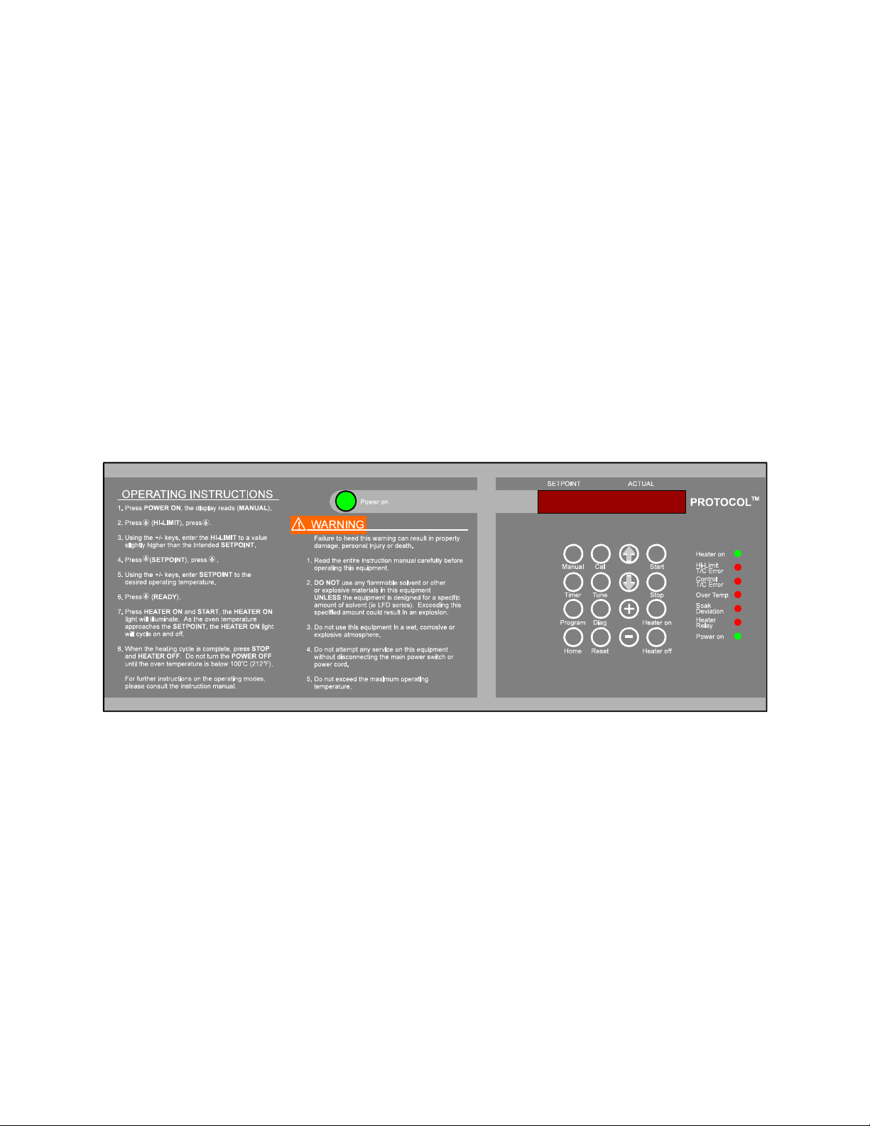
Figure 2. Main Display and Keypad on Protocol Control
The Despatch Protocol temperature controller is a dual functioning controller/high limit
instrument. The control portion of Protocol incorporates a microprocessor to digitally
control process variables with minimal temperature fluctuations.
The high limit portion of Protocol protects the product and/or the oven itself. If the
product being processed has a critical high temperature limit, the Hi-Limit parameter
should be set to a temperature somewhat below the temperature at which the product
could be damaged. If the product does not have a critical high temperature limit, the HiLimit parameter should be set to a value slightly higher than the highest programmed
setpoint to protect the oven equipment.
2
Page 9
Keypad Controls
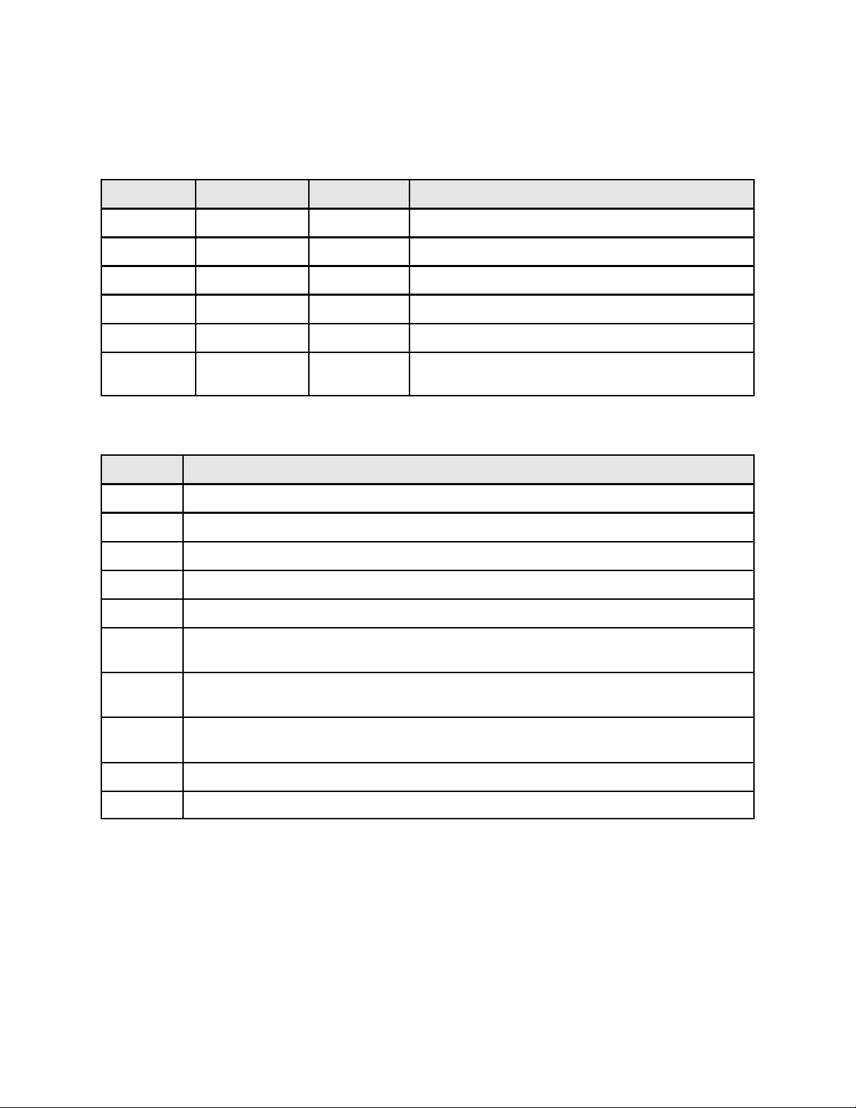
Table 1 Protocol Keypad Controls
Mode Display Code Function Description
Manual MANUAL Operation Single setpoint control
Timer TIMER Operation Single setpoint control with process timer
Program PROGRAM Operation Programmable control with three event outputs
Tune TUNE Configure Set instrument parameters
Calibrate CAL-MODE Service Performs instrument calibration
Diagnostics DIAGNOSE Service Performs instrument thermocouple tests, SSR
power level and event output tests.
Table 2 Protocol Touchkeys
Key Description
• To move up through any mode
– To move down through any mode
+ To increase a setpoint or parameter
- To decrease a setpoint or parameter
Home To move to the beginning of any mode or segment
Reset To reset the control when an error has been corrected or to view the profile number,
segment number, and the number of loops (repeat times) remaining.
Heater
On
Heater
Off
Start To start an operating mode
Stop To stop an operating mode
To initiate heater relay
To disengage heater relay
3
Page 10
Status Indicator LEDs
Protocol has seven indicator LEDs that provide the following relevant information to the
user.
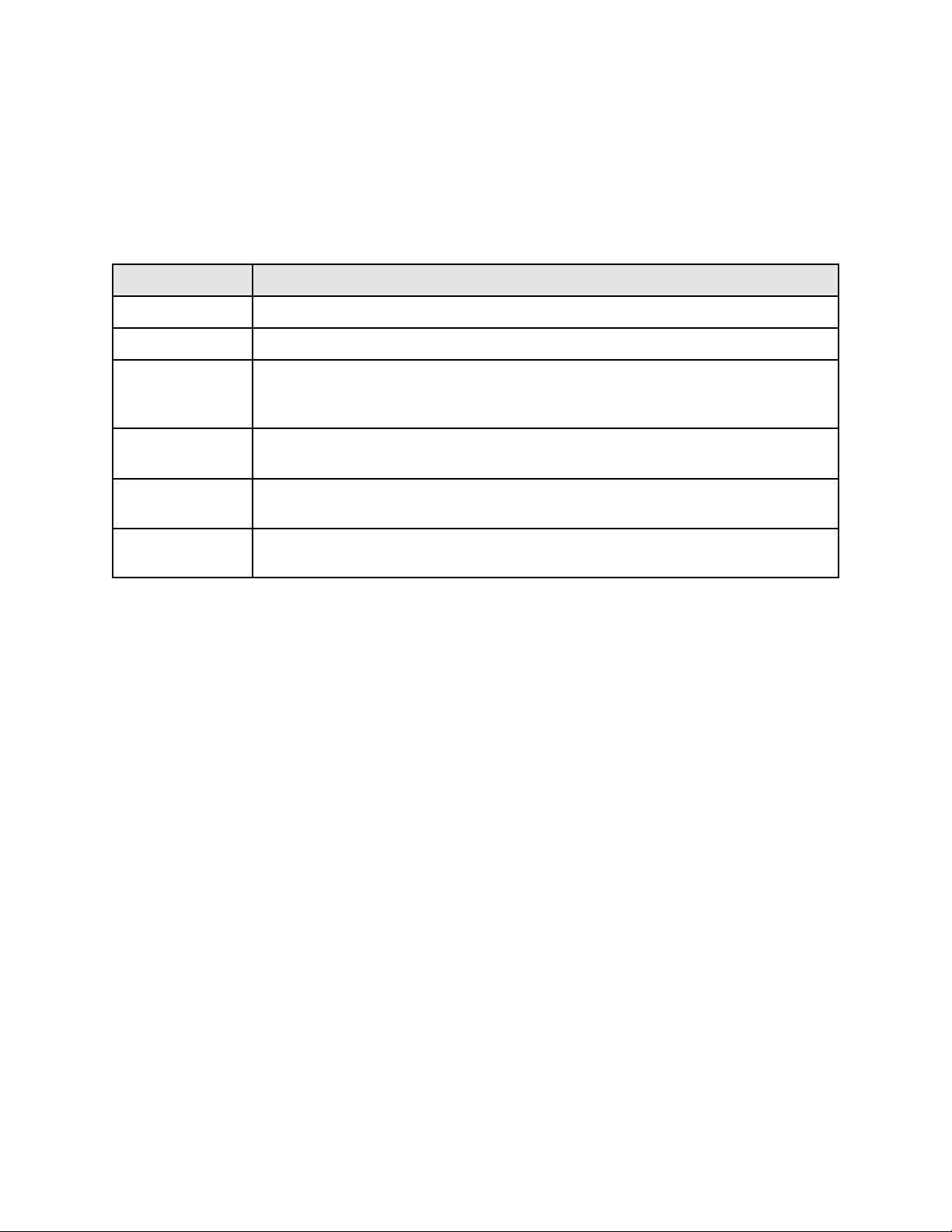
Table 3 Protocol Indicator LEDs
LED Function
Power on Lights when the power on pushbutton is pressed.
Heater relay Lights when a mode is ready for operation and the heater on key is pressed.
Soak Deviation Lights when the process temperature is not held within the user-specified soak
deviation limits. The light turns off when the temperature is within the soak
deviation limit.
Over Temp Lights when the process temperature exceeds the high limit value. The over
temperature light remains lit until the Reset is pressed.
Control T/C Error Lights when Lights when Protocol receives a control thermocouple error. the
Reset key clears the error upon corrective action.
Hi-Limit T/C
Error
Lights when Protocol receives a hi-limit thermocouple error. The Reset key
clears the error upon corrective action.
The Despatch Protocol temperature controller has been designed for ease of use while
maintaining elaborate and versatile control capabilities.
4
Page 11

Operating Modes
Protocol has three primary modes of operation: the Manual mode, the Timer mode and
the Program mode.
Manual Mode
The Manual mode is a single setpoint control mode that controls the process at the user
specified setpoint for an indefinite period of time. The Manual mode controls the oven
temperature within close limits as specified by the PID tuning parameters.
Timer Mode
The Timer mode is a single setpoint control mode with a built-in process timer that
starts timing either at the beginning of the process or at a user specified temperature.
As in the Manual mode, the Timer mode uses the PID parameters set in the tune mode.
Program Mode
The Program mode is a programmable ramp and soak control consisting of up to eight
profiles. Each profile consists of up to six segments for a total of 48 segments (8 x 6 =
48). Any one profile may be run recursively from two to 99 cycles or even continuously
if it is desired.
Each segment consists of a ramp and soak period. During the ramp period, the control
will track oven temperature. For example, a ramp is entered to heat from 100E C to
150E C in 50 minutes. Protocol will track the temperature 1E C every minute for 50
minutes. During the soak period, temperature is maintained as specified by the tuning
and soak deviation parameters.
Protocol will not allow a soak time to begin until the actual oven temperature is within
the soak deviation limit. This process is called assured soak. The ramp and soak
periods are adjustable from 0 to 99 hours, 59 minutes. Within each ramp and soak
period, up to three event outputs can be programmed either on or off.
The event relay is used for factory installed modifications, then disconnected before
shipping. Please consult the factory for information on connecting the event outputs.
When the events are connected, the user has the capability of controlling relays,
solenoid valves, etc., throughout the programming cycle.
5
Page 12
Calibration Zero Offset
The Calibration Zero Offset (CZO) of Protocol is factory preset and tested for the
specified operating conditions. Special instructions for accessing the tune mode to
change the CZO are referred to in the Appendix of this manual.
Figure 3. CZO Function in Tune Mode
The CZO may be useful to make the following small temperature corrections to the
control system.
C Correction of known sensor calibration errors.
C Correction of any known steady temperature offset between the heated
work-piece (load) and sensor. This is useful for applications where the sensor
cannot be located exactly at the work-piece.
C Alignment of temperature indications in a multi-zone/multi-controller application,
e.g., at ambient temperature.
Note that the CZO changes the value of the controlled temperature when used in
closed loop control. The CZO function can be represented by the equations:
Temp Indication (EF) = Sensor Temp (EF) - CZO% [100 (EF) - Sensor Temp (EF)]
Temp Indication (EC) = Sensor Temp (EC) - CZO% [38 (EC) - Sensor Temp (EC)]
The CZO function is a straight line pivoted around 100E F (38EC). Thus, the CZO
functions as an offset and has the ability to change the SLOPE of a temperature range.
6
Page 13
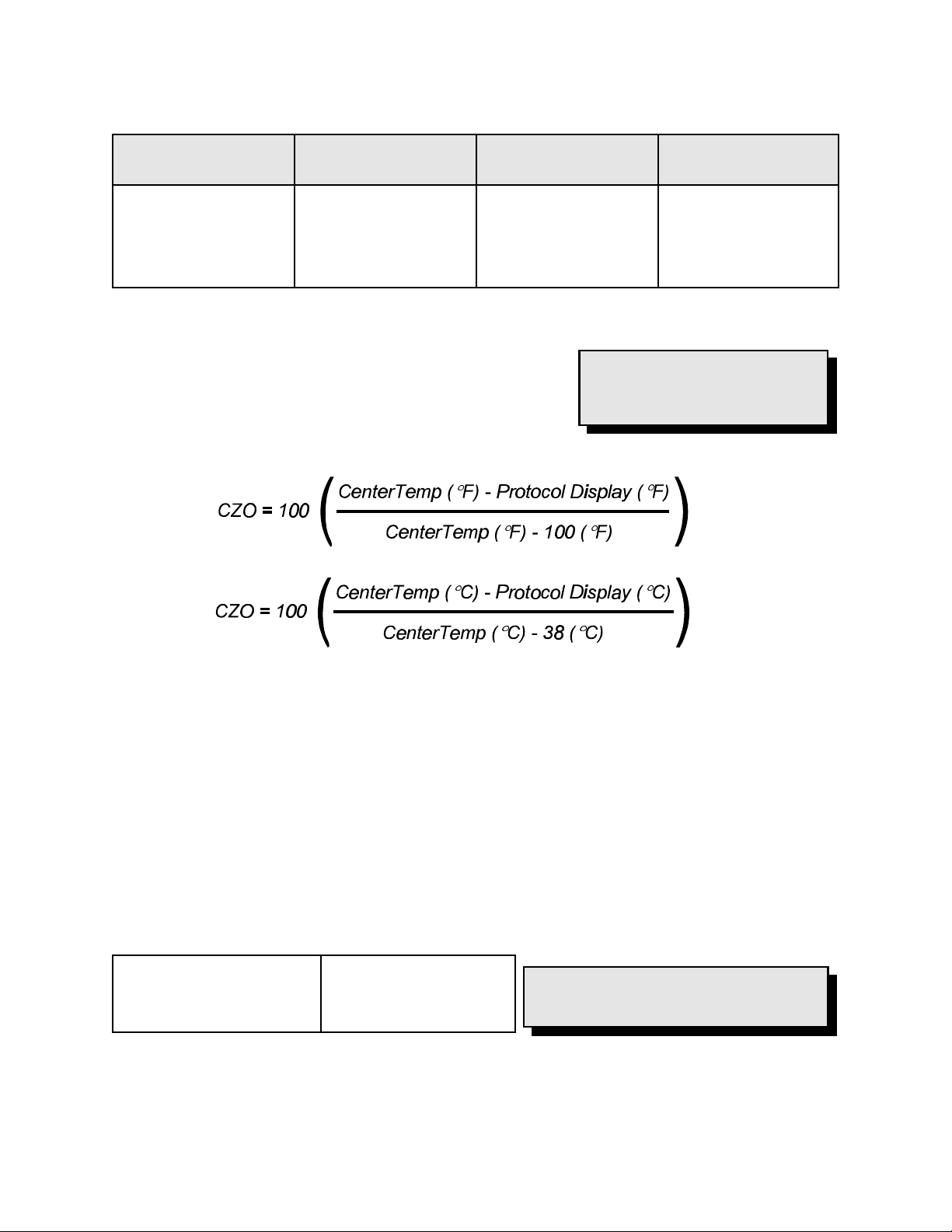
Table 4 Calibration Zero Offset Examples
CZO Display Temperature
measured by sensor
0.0
4.0
10.0
10.0
-10.0
100 EF
150 EF
150 EF
300 EF
300 EF
Offset EF Temperature Indication
-20 E
A more useful formula is one the user can use to
calibrate Protocol to match the center of the chamber.
This requires a temperature measuring device with its
thermocouple junction located at the center of the
chamber. CZO can be directly calculated by:
0 E
2 E
5 E
20 E
NOTE: The CZO function is
easily set for specific operating
conditions.
100 EF
152 EF
155 EF
320 EF
280 EF
Tune Setting
The Protocol has been preset and tested for normal operating conditions. Special
instructions for changing the tune setting are referenced in the Appendix of this manual.
The Protocol on the oven can be manually tuned. For your convenience the factory has
tested and preset the PID action to its optimum values. These values need not be
changed under normal operating conditions.
Table 5 Factory PID Settings
Proportional Band
Reset Time
Rate Time
5 degrees
30 seconds/repeat
0 degrees/second
7
NOTE: Reset times greater than 35
seconds/repeat are not recommended.
Page 14

Protocol Hi-Limit
Protocol will not let the high limit value drop below the setpoint value. In certain
situations, it may be necessary to change the setpoint first and then adjust the high limit
value.
It will be necessary to reset the hi-limit whenever it
has tripped. The hi-limit may be reset by first
allowing the oven chamber to cool slightly (or
increasing the parameter by several degrees) and
pushing the Reset key. During a high limit condition
the Over Temp LED will turn on thus deactivating
the heater.
WARNING: Never operate the
oven at a temperature in excess
of the maximum operating
temperature.
8
Page 15

INSTRUCTIONS
Start-Up
An outline and examples for the Manual mode, Timer mode and Program mode are
referenced in the Appendix. A completed typical program worksheet accompanies all
programmable event outputs installed at the factory.
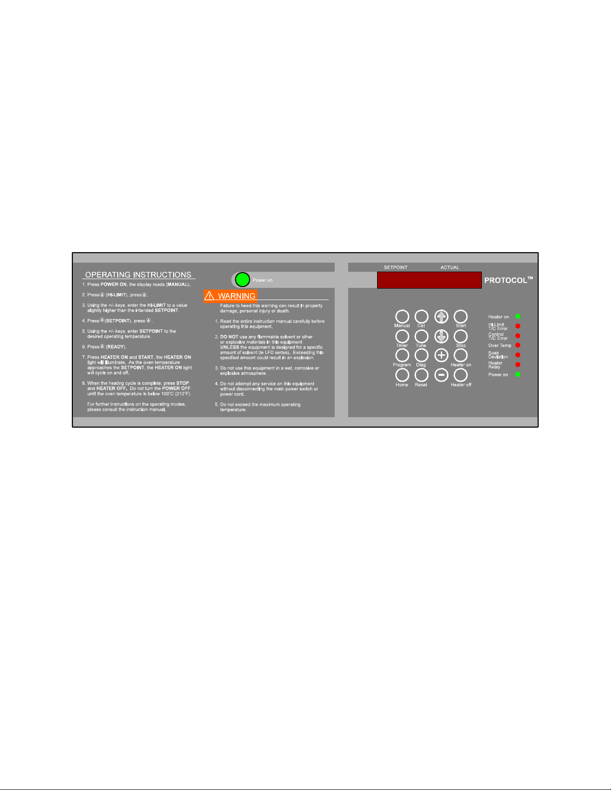
1. Start Fan.
a. Press Power on pushbutton. You will hear the recirculating fan start.
b. Check that the green Power on LED is on.
Figure 5. Protocol Control Panel
9
Page 16

Manual Mode
Startup
The following are startup instructions for the Manual mode.
1. Select Manual mode.
a. Press the Manual key. MANUAL will be displayed.
2. Enter the high limit temperature.
a. Press – key. HI-LIMIT will
be displayed.
b. Press – key.
c. Using the +/- keys, enter the high limit temperature to a value slightly
higher than the intended SETPOINT.
3. Enter the Setpoint.
a. Press – key. SETPOINT
will be displayed.
b. Press – key.
c. Using the +/- keys, enter
the SETPOINT to the desired operating temperature.
Run
NOTE: For safety reasons, Protocol will not let
the operator set the Hi-limit below the setpoint.
It may be necessary to adjust the Protocol
setpoint first, then adjust the Hi-limit.
NOTE: During processing the
display shows the setpoint on the left and the
actual oven temperature on the right.
The following are run instructions for the
Manual mode.
NOTE: When Protocol is run in the Manual
1. Press – key. READY will be
displayed.
2. Press Heater on key. The Heater
relay LED will illuminate.
3. Press Start key. The Heater on LED will illuminate. As the oven temperature
approaches the setpoint, the Heater on LED will cycle on and off.
Mode, the setpoint can be adjusted without
stopping the operation. The setpoint is
adjusted by using the +/- keys.
10
Page 17

Stop
The following are stop instructions for the Manual mode.
1. Press the Heater off key. The Heater Relay LED will shut off.
2. Wait for oven temperature to fall below 100E C (212E F).
3. When the Manual mode is complete, press the Reset key to display the final
process temperatures.
4. Press the Stop key.
5. Press the Power on pushbutton to turn power off.
An example of the Manual mode is referenced in the Appendix.
11
Page 18

Timer Mode
Startup
The following are startup instructions for the Timer
mode.
1. Select Timer mode.
a. Press Timer key. TIMER will be
displayed.
2. Enter the high limit temperature.
a. Press – key. HI-LIMIT will be
displayed.
b. Press – key.
c. Using the +/- keys, enter the high limit temperature to a value slightly
higher than the intended setpoint.
3. Enter the Setpoint.
NOTE: During processing the
display shows the setpoint on the
left and the actual oven temperature on the right.
NOTE: For safety reasons, Protocol
will not let the operator set the Hilimit below the setpoint. It may be
necessary to adjust the Protocol
setpoint first, then adjust the Hi-limit.
a. Press – key. SETPOINT will be displayed.
b. Press – key.
c. Using the +/- keys, enter the SETPOINT to the desired operating
temperature.
4. Enter the process time.
a. Press – key. TIME will be displayed.
b. Using the +/- keys, enter the time of the process. (HHMM (hours/minutes)
or MMSS (minutes/ seconds) selected in the tune mode).
5. Enter timer starting temperature.
a. Press the – key. TEMP YES/NO will be displayed.
12
Page 19

b. Use the + or - keys to select either YES or NO.
C Press the - key to display NO and begin timing at ambient.
C Press the + key to display YES and begin timing at the following
input temperature.
c. Press the – key. TEMP and the begin timing temperature will be
displayed.
d. If YES was selected in step b, use the + or - keys to enter the temperature
at which the process timer begins timing.
If NO was selected in step b, this setpoint has no bearing on oven
operation.
Run
The following are run instructions for the Timer mode.
1. Press the – key. READY will be displayed.
NOTE: When the Timer mode is
2. Press the Heater on key. The Heater Relay
LED will illuminate.
3. Press the Start key. The Heater on LED will
illuminate and the setpoint and the actual
running, pressing the Start key will
display the time remaining in the
cycle. The display will show
TRHHMMSS which stands for the
time remaining, hours, minutes
and seconds.
temperature will be displayed. As the oven
temperature approaches the setpoint, the
Heater on LED will cycle on and off.
Manually Stop
The following are manual stop instructions for the Timer mode.
1. Press the Heater off key.
2. Wait for oven temperature to fall below 100E C (212E F).
3. When the Timer mode is complete, press the Reset key to display the final
process temperatures.
4. Press the Stop key.
13
Page 20

5. Press the Power on pushbutton to turn power off.
An example of the Timer mode is referenced in the Appendix of this manual.
14
Page 21

Program Mode
Startup
The following are startup instructions for the
Program mode.
NOTE: If all event relays are
disconnected or no modifications
involving event relays have been
made to your particular oven,
programming the events has no
effect on oven operation.
NOTE: All profiles entered can be
cleared by using the PROF CLR
function in the TUNE mode.
In any one segment, if the ramp and soak times are
zero, Protocol ignores the remaining segments of the profile. A soak period will not
begin until the actual oven temperature is within the soak deviation limit. During any
segment of a profile, if the actual oven temperature falls outside of the soak deviation
limit, the Soak Deviation LED will be illuminated.
1. Select Program mode.
a. Press Program key. PROGRAM will
be displayed.
2. Enter the high limit temperature.
a. Press – key. HI-LIMIT will be
NOTE: For safety reasons,
Protocol will not let the operator
set the Hi-Limit below the setpoint.
It may be necessary to adjust the
Protocol setpoint first, then adjust
the Hi-Limit.
displayed.
b. Press – key.
c. Use the + or - keys to enter the high limit temperature to a value higher
than the intended setpoints.
3. Enter the profile number.
a. Press – key. PROFILES will be displayed.
b. Press – key. PRO - 1 will be displayed.
c. Use the + or - keys to enter the profile number to program.
4. Program the profile.
a. Press – key. SEG - 1 will be
displayed.
b. Program the ramp rate.
1. Press – key. RAMP0001 will
be displayed.
NOTE: During processing the
display shows the setpoint on the
left and the actual oven
temperature on the right.
15
Page 22

2. Use the + or - keys to enter the ramp time.
c. Program the events desired during the ramp time.
1. Press – key. EVENTS will be displayed.
2. Press – key for each event.
3. Use the + or - keys to program the event outputs ON or OFF for the
ramp period.
d. Program the ramp ending temperature.
1. Press – key. TEMP and the ramp ending temperature will be
displayed.
2. Use the + or - keys to enter the desired ramp ending temperature.
e. Program the soak time.
1. Press – key. SOAK and the
WARNING: Never operate the oven
at a temperature in excess of the
maximum operating temperature.
soak time will be displayed.
2. Use the + or - keys to enter the soak time.
f. Program the events desired during the soak time.
1. Press – key. EVENTS will be displayed.
2. Press – for each event.
3. Use the + or - keys to program the event ON or OFF for the soak
period.
g. Enter the remaining segments 2-6 by following steps a through f.
16
Page 23

5. Enter the Soak-Deviation.
a. Press – key until SOAK-DEV is
displayed.
b. Press a key. The symbol +/- will be
displayed.
c. Use the + or - keys to enter the soak deviation limit.
6. Enter the next profile to continue to, or end profile.
a. Press – key. GOTO will be displayed.
b. Use the + or - keys to enter the profile number to continue to. Select End
to stop at the end of this profile. For continuous profiles enter the same
number of the profile that is currently being programmed.
7. Enter the number of profile recursions.
a. Press – key. REPEAT will be displayed.
NOTE: The SOAK-DEV limit is
also the assured soak limit. This
means that the soak times will not
begin until the process
temperature is within the SOAKDEV parameter.
b. Press – key. TIMES will be displayed.
c. Use the + or - keys to enter the number of times to complete the profile
being programmed (1 - 99).
8. Enter the profile end condition. The hold
command is contingent on the final segment
of the last profile to be run only.
a. Press – key. HOLD will be displayed.
b. Use the + or - keys to select YES or
NO.
C Selecting YES will hold at last setpoint. The event outputs will be
held at their last value.
C Selecting NO will not hold at last setpoint. The event outputs will
be turned off.
NOTE: If the Protocol is in a hold
condition, pressing the Reset key
will display that the control is in
segment 7 (HOLD).
17
Page 24

Run
The following are run instructions for the Program
mode.
1. Press Home key until PROGRAM is
displayed.
NOTE: When in the Program
mode, pressing the Start key will
display the time remaining in the
cycle (TRHHMMSS). Pressing the
Reset key will display the profile
number, segment number and the
loops (REPEAT TIMES)
remaining.
2. Press – key until PRO-1 is displayed.
3. Make sure the correct starting profile is entered by pressing + or -.
4. Press the • key until READY is displayed.
5. Press Heater on key. The Heater relay LED will illuminate.
6. Press Start key. The Heater on LED will illuminate. As the oven temperature
approaches the setpoint, the Heater on LED will cycle on and off. During
processing, the display shows the setpoint on the left and the actual oven
temperature on the right.
Manually Stop
The following are manual stop instructions for the Program mode.
1. Press Heater off key.
2. Wait for oven temperature to fall below 100EC (212EF).
3. Press the Reset key to display the final process temperature.
4. Press Stop key.
5. Press Power on pushbutton to turn power off.
Examples of the Program mode are referenced in the Appendix of this manual.
18
Page 25

APPENDIX
Special Instructions
The Protocol has been preset and tested at the factory for normal operating conditions.
In most applications, it will not be necessary to alter the oven's settings. This section
contains additional information and reference for special operating conditions.
19
Page 26

Control Instrument
Tune Mode
Various functions of the control instrument are set by parameters in the tune mode. To
access the tune mode, it is necessary to enter the proper code.
1. Press Tune key. The display reads TUNE.
2. Press – key. CODE *** will be displayed.
3. Enter +, -, -, +, -, +. PID TUNE will be displayed.
The PID tuning parameters may be entered. The units are listed below.
P = degrees
I = seconds/repeat
D = degrees/second
20
Page 27

Table 6 Tuning Outline
Display Description
TUNE
CODE
PID TUNE
P-1
I-1
D-1
DEG SPL CZO DIS
BEEP
PF-RECVR
DIG COMM
RECONFIG
PROF CLR
VARS CLR
CODE *E*
Selects tune mode.
Enter + - - + - +
Enter tuning parameters.
Proportional band in degrees (+/- keys).
Reset in seconds/repeat (+/- keys).
Rate in degrees/second keys).
Select EC or EF (+/- keys).
Setpoint limit, set to maximum temperature of oven (+/- keys)
Calibration zero offset -99.9 to 99.9 (+/- keys).
Time set in MMSS (minutes/seconds) or HHMM (hours/minutes).
Select beep on or off (+/- keys).
Power failure recovery mode. Use + or - keys to select from STOP, RESUME or
HOLD.
C STOP - Program terminates. must restart from the beginning of the program.
C RESUME - When power is restored, program resumes at the point where power
failure occurred.
C HOLD - Program waits for the operator. The operator has a choice of terminating
or resuming the program.
Digital communications option. Disregard unless Protocol is supplied with optional
digital communications interface. For proper setting, refer to the protocol software
manual or the Digital Communication User Guide. Select from NO COMM, CPIF or
ASCII (+ or - keys). Select from RS232C or RS422A (+ or - keys). Select address
(ADDR) from 1 to 999 (+ or - keys).
C NO COMM - No digital communication.
C CPIF - Computer interface mode communications (used for Protocol software)
C ASCII - ASCII line mode communications (used for user-created programs)
For saving changes to DIG COMM options in memory.
Entering code clears all profiles to default values.
Entering code clears the SRAM in Protocol. All parameters must be reset. Should be
done in EXTREME circumstances only. Recalibration is essential.
To turn events relays on in the profile mode. Do not change the code setting.
Experience and experimentation with tuning parameters will guide the user in
determining the proper settings when normal conditions are not present.
21
Page 28

Tuning Worksheet
In most applications it is not necessary to alter tuning parameters. To enter the tune
mode, press the Tune key. Tune will be displayed. Press – and enter +, -, -, +, -, +.
Using the – key and the +/- keys, enter the desired settings. Press Home when
finished.
Tuning Worksheet
Display Setting Factory Setting Units
P-1 5 degrees
I-1 30 seconds/repeat
D-1 0 degrees/second
DEG - C EF (EC)
SPL - Max Temp EF (EC)
CZO varies factor calibrated to center of the chamber
DIS - HHMM minutes/seconds (hours/minutes)
BEEP On off (on)
Notes:
1. The alternate is listed in ( ).
2. See Table 10, Tuning Outline, for further information regarding display codes.
3. Tuning parameters may change from those set at the factory. Load mass, fresh air
and exhaust damper settings will affect tuning parameters. Some experimentation is
required to determine optimum settings.
Reset times greater than 35 seconds/repeat are not recommended.
22
Page 29

Calibration Mode
Protocol has been tested and calibrated at the factory. Under normal operating
conditions recalibration should not be necessary. However, if the instrument does not
comply with known standards recalibration may be necessary.
Calibration Instructions
We recommend using a certified analog
thermocouple simulator/calibration source with less
than ±1E F noise. We have experienced signal
stability problems with some microprocessor based
thermocouple simulator/calibrators which induce an
error during the calibration procedure. This error
WARNING: Calibration
equipment without internal
ambient compensation provisions
requires subtracting the ambient
mV signal from the calibration
temperature mV signal to
calibrate Protocol properly.
generally results in a non-linear shift in the
controller's indicated temperature.
1. Disconnect AC power to the oven.
2. Remove Protocol controller to expose thermocouple input terminals.
3. Disconnect control and Hi-Limit thermocouples from controller thermocouple input
terminals (Control T/C, and Hi-Limit T/C).
Figure 6. Top View of J Type Thermocouple Inputs on Protocol
4. Mark thermocouple leads if not labeled.
5. Connect a 6 foot piece of type J thermocouple lead wire to each of the Control T/C
and Hi-Limit T/C terminals.
6. Twist together or jumper the lead wire end not connected to the Control T/C and
Hi-Limit T/C terminals. This creates a junction and prevents a control sensor error
[S-T/C ERR] and Hi-Limit sensor error [H-T/C ERR] caused by an open
thermocouple.
23
Page 30

All errors must be cleared to perform calibration. Any active error will inhibit the calibration function.
To clear a Hi-Limit control error [HL ERROR] caused by lost of calibration (Hi-Limit indication of
500E C or 932E F in the diagnostic mode):
1. Increase the Hi-Limit setpoint to 500E C or 932E F.
2. Press the Reset key.
7. Loosely fasten the Protocol controller to the oven.
8. Re-connect AC power to the oven.
9. Press the Power on pushbutton to energize oven.
10. Press the Tune key. The display reads [TUNE ].
11. Use the – and • keys to scroll through the tune mode configuration. The
controller must be configured to operate in EF (Fahrenheit) and CZO
should be set to zero (0.0).
a. Record initial tune mode parameters prior to making any changes.
b. Press the – key. The display reads [CODE ***].
c. Press the following key sequence: +, -, -, +, -, +.
The display reads [PID TUNE]. Protocol is in the tune mode.
d. Use the following table to change the tune mode parameters.
24
Page 31

Tune Mode Parameter Calibration
NOTE: ### or ##.# represents a numeric value or parameter.
Press Display Factory Default
Setting
– key P-1 ### 5 + or - keys 0E C to 500E C
– key I-1 ### 30 + or - keys 0 to 999
– key D-1 ### 0 + or - keys 0 to 999
– key DEG - C C + key for C or - key for F.
– key SPL - ### maximum designed
operating
temperature¹
– key CZO - ##.# can vary + or - keys to change
– key DIS
HHMM
– key BEEP ON ON + key for ON or the - key
HHMM + key for HHMM (hours
Actual
Setting
Press Adjustable Range
32E F to 932E F
seconds/repeat
degrees/second
+ or - keys 0E C to 500E C
32E F to 932E F
-99.9 to 99.9
parameter to 0.0
and minutes) or the - key
for MMSS (minutes and
seconds).
for OFF.
degrees
¹ 204E C/400E F, 260E C/500E F, 343E C/650E F
e. Press the Manual key. The display reads [MANUAL ].
f. Allow the controller a thirty (30) minute warm up time before proceeding to
the step #13 - CAL MODE.
12. Press the Cal key. The display reads [CAL--MODE].
13. Press the – key. The display reads [CODE ***].
14. Press the following key sequence: -, +, +, -, +, -.
The display reads [HCAL 250].
25
Page 32

15. Apply a 250E F signal to the high limit thermocouple input:
a. Connect the piece of type J thermocouple lead wire, wired to the High
Limit T/C terminals, to a thermocouple simulator.
b. Set the simulator to output a type J thermocouple signal.
c. Twist together or jumper the piece of type J thermocouple lead wire, wired
to the Control T/C terminals. This creates a junction and prevents a
Control sensor error [S-T/C ERR] caused by an open thermocouple.
Press the Reset key to clear a Control sensor error [S-T/C ERR] caused
by an open thermocouple.
d. Adjust the simulator to supply a 250E F signal. Wait for 30 seconds while
the control stabilizes.
16. Press the following key sequence: -, -, +. The display now reads HCAL
450.
17. Adjust the simulator to supply a 450E F signal. Wait for 30 seconds while
the control stabilizes.
18. Press the following key sequence: +, +, -. The display now reads HIL 450.
19. To verify proper calibration, adjust the simulator to supply a 350E F signal.
Within 30 seconds, the display should stabilize and read HIL 350.
20. To calibrate the control sensor, press the – key. The display reads
[SCAL 250].
21. Apply a 250E F signal to the control thermocouple input:
a. Connect the piece of type J thermocouple lead wire, wired to the Sensor
T/C terminals, to a thermocouple simulator.
b. The simulator should be set to output a type J thermocouple signal.
c. Twist together or jumper the piece of type J thermocouple lead wire to the
Hi-Limit T/C terminals. This creates a junction and prevents a hi-limit
sensor error [H-T/C ERR] caused by an open thermocouple. Press the
Reset key to clear a hi-limit sensor error [H-T/C ERR] caused by an
open thermocouple.
d. Adjust the simulator to supply a 250E F signal. Wait for 30 seconds while
the control stabilizes.
26
Page 33

22. Press the following key sequence: -, -, +. The display now reads SCAL
450.
23. Adjust the simulator to supply a 450E F signal. Wait for 30 seconds while
the control stabilizes.
24. Press the following key sequence: +, +, -. The display now reads SENS
450.
25. To verify proper calibration, adjust the simulator to supply a 350E F signal.
Within 30 seconds, the display should stabilize and read SENS 350.
26. Press the Manual key. The display reads [MANUAL]. If the control did
not calibrate properly repeat steps 12 - 25.
27. Press the Power on pushbutton to de-energize oven.
28. Disconnect AC power to the oven.
29. Remove Protocol controller to expose thermocouple inputs terminals.
30. Disconnect the two pieces of type J thermocouple lead wire connected to
the Control T/C and Hi-limit T/C terminals.
31. Re-connect control and Hi-Limit thermocouples to the controller
thermocouple terminals (Control T/C, and Hi-limit T/C).
32. Re-install the Protocol controller onto the oven.
33. Re-connect AC power to the oven.
34. Press the Power on pushbutton to energize oven.
35. Press the Tune key. The display reads [TUNE ].
36. Reset any tune mode parameters that were changed in step 12 to perform
calibration (examples: DEG = F and CZO = 0.0).
37. When changes have been completed, press the Manual key. The display
reads [MANUAL ].
The calibration procedure is complete.
27
Page 34

Calibration Recovery
The Protocol control has a factory calibration recovery feature. This feature allows the
operator to restore the Protocol to an operational condition should a calibration error
occur. The Factory Calibration Recovery feature should only be used as a temporary
fix until a proper calibration procedure utilizing a calibration source can be performed.
Only a complete calibration will restore the Protocol to an optimum performance level.
For proper calibration instructions refer to the calibration section of this manual.
Instructions
1. Select the Diagnose mode by pressing the DIAG key.
2. Press the – (down arrow) key until RCVR SEN is displayed.
3. To recover the control sensor calibration value, press the key sequence +, -, -, +, -,
+.
4. Press the – (down arrow) key until RCVR HIL is displayed.
5. To recover the high limit sensor calibration value, press the key sequence +, -, -, +, -,
+.
The calibration recovery is now complete.
28
Page 35

Diagnostics Mode
The diagnostics mode is provided to give certain relative information about Protocol.
The following table gives an outline of the diagnostics mode.
Display Description
DIAGNOSE Select Diagnostics mode.
SSR Protocol SSR output level.
EVENTS Events 1-3 follow
E-1 Event 1 output
E-2 Event 2 output
E-3 Event 3 output
SENS-T/C Control thermocouple display follows
GOOD Control thermocouple test and input reading
HL - T/C Hi-limit thermocouple display follows
GOOD Hi-limit thermocouple test and input reading
PWR % output
RCVR SEN Recover factory calibration for control sensor
RCVR HIL Recover factory calibration for high limit sensor
Items that can be adjusted by the user include SSR (ON or OFF), Events E-1, E-2 and
E-3(ON or OFF) and PWR. The SSR and PWR items can be used to test the solid
state relay for proper operation. The SSR item allows the SSR to output 100% (ON) or
0% (OFF). The PWR item allows for adjustable output from 0% to 100%. to
implement, adjust the PWR level with the +/- keys and turn on the heater relay.
RCVR SEN and RCVR HIL are used to restore the factory calibration should a
calibration error occur.
29
Page 36

Power Failure
In the event that the power supplied to Protocol is insufficient at any point during a
running mode, the display will read PWR-FAIL. In the tune mode the user can choose
the Power Fail Recovery mode from Stop, Resume and Hold. To restart after a power
failure in the hold mode, press the Start key to resume oven operation. Otherwise,
press the Reset key to clear the PWR-FAIL display. Do not shut off the power during a
running mode. This creates an error condition and PWR-FAIL will be displayed the
next time Protocol is powered up. Instead, press the Stop key and the Heater Off key.
This will power off Protocol without creating an error condition.
30
Page 37

Programming Examples and Outline
The following examples show a step by step procedure for
programming Protocol in the Manual, Timer and Program
modes. Example 1 covers the Manual mode and example 2
covers the Timer mode. A detailed outline covers the Program mode with a programming worksheet and examples 3-5
following the outline.
NOTE: Do not turn the
power off until the oven
temperature is below
100EC (212EF).
Example 1 - Manual Mode
Control the process at 250EF.
Manual Mode Example
Key DISPLAY Description
Manual
?
?
+
?
?
+
?
Heater On
MANUAL
Hi-Limit
HL 200
HL 275
SETPOINT
180 75
250 75
READY
READY
Select Manual mode
Enter the high limit temperature
High limit temperature currently set at 200EF
Increase high limit temperature to 275EF
Enter the setpoint
Setpoint at 180EF, actual oven temperature at 75EF
Increase setpoint to 250EF
Protocol is ready to run Manual mode
Heater relay initiated, heater ready for power
NOTE: EF is selected in the tune
mode.
Start
Stop
Heater Off
250 75
READY
READY
Setpoint = 250EF, actual oven temperature = 75EF
Stop Manual mode
Heater relay LED is off, heater secured off
31
Page 38

Example 2 - Timer Mode
Control the process at 200EC for three hours and 15
minutes with the timer beginning at 195EC. Protocol
will stop automatically when run in Timer mode.
Timer Mode Example
Key DISPLAY Description
Timer
?
?
-
?
?
-
?
+
TIMER
Hi-Limit
HL 225
HL 215
SETPOINT
210 25
200 25
TIME0010
TIME0315
Select timer mode
Enter the high limit temperature
Hi-Limit currently set at 225EC
Decrease high limit to 215EC
Enter the setpoint
Setpoint at 210EC, actual oven temperature at 25EC
Decrease setpoint to 200EC
Timer currently set for ten minutes
Increase timer to three hours and 15 minutes
NOTE: EC and HHMM
(hours/minutes) is selected in the
tune mode.
?
+
?
+
?
Heater On
Start
Stop
Heater Off
TEMP NO
TEMP YES
TEMP 79
TEMP 195
READY
READY
200 25
READY
READY
Timer currently set to begin timing at ambient
Timer set to begin timing at the following temperature
Timer currently set to begin timing at 79EC
Timer set to begin timing at 195EC
Protocol is ready to run Timer mode
Heater relay LED on, heater ready for power
Setpoint = 200EC, actual oven temperature = 25EC
Stop Timer mode
Heater relay LED is off, heater secured off
32
Page 39

Program Mode
Program Mode Outline
Display Description
PROGRAM
Select Program mode.
Hi-Limit
HL
PROFILES
PRO SEG RAMP
EVENTS
E-1
E-2
E-3
TEMP
SOAK
EVENTS
E-1
E-2
E-3
SOAK-DEV
+/-
Hi-Limit for Program mode
Enter high limit temperature (+ or - keys).
Enter profile number (1-8).
Segment number of profile (1-6)
Ramp time entered
Event status for ramp time
Event 1 status (ON or OFF)
Event 2 status (ON or OFF)
Event 3 status (ON or OFF)
Ramp ending temperature
Soak period of ramp ending temperature
Event status for soak period
Event 1 status (ON or OFF)
Event 2 status (ON or OFF)
Event 3 status (ON or OFF)
Soak-Deviation limit for profile (Also assured soak limit)
Enter soak-deviation limit.
GOTO
REPEAT
TIMES
HOLD
YES
NO
Enter profile to GOTO
End = Move to REPEAT TIMES command
1 = GOTO profile 1
2 = GOTO profile 2
:
8 = GOTO profile 8
Enter number of recursions (1-99)
1 = Execute profile 1 times
2 = Execute profile 2 times
:
99 = Execute profile 99 times
Hold at last setpoint?
Hold at last setpoint indefinitely.
Holds event outputs at last value.
No hold at last setpoint.
Event outputs turn OFF.
Notes on the Program mode:
33
Page 40

C The profile number is manually entered using the + or - keys.
C Six segments exist for each profile.
C If the ramp time and soak time for any one segment is zero, Protocol ignores the
remaining segments.
C The REPEAT TIMES command is the number of times to execute the profile being
programmed.
C The HOLD command is contingent on the final segment of the last profile to be run
only.
C A soak time will not begin until the actual temperature is within the soak-deviation
limit. (Assured soak limit).
C Make sure the proper starting profile number is displayed in the PRO- prompt before
executing the profile to be run.
While a program is being executed, pressing the Reset key will display the profile
number, segment number and the number of loops (REPEAT TIMES) remaining.
Pressing the Start key will display the appropriate ramp or soak time remaining (TR.)
If Protocol is in a HOLD condition, pressing the Reset key will display that the control is
in segment 7 (HOLD.)
34
Page 41

Program Worksheet
The program worksheet serves as a guide to the input parameters for the program
mode.
Figure 7. Sample Profile
Display Setting(s)
HL _____
PRO- _____
SEG- 1 2 3 4 5 6
RAMP _____ _____ _____ _____ _____ _____
E-1 _____ _____ _____ _____ _____ _____
E-2 _____ _____ _____ _____ _____ _____
E-3 _____ _____ _____ _____ _____ _____
TEMP _____ _____ _____ _____ _____ _____
SOAK _____ _____ _____ _____ _____ _____
E-1 _____ _____ _____ _____ _____ _____
E-2 _____ _____ _____ _____ _____ _____
E-3 _____ _____ _____ _____ _____ _____
SOAK-DEV _____
GOTO _____
REPEAT TIMES _____
HOLD _____
35
Page 42

Example 3 - Program Mode
Follow the characteristic curve listed below.
Figure 8. Example Temperature Profile
Display Setting(s)
NOTES: HHMM
(hours/minutes) and EC selected
in the tune mode. No event
outputs are being used. SoakDeviation limit = ±7EC (also
assured soak limit). Hold at last
setpoint. Ramp and soak times
of zero in any one segment
ignores remaining segments.
HL 150
PRO- 1
SEG- 1 2 3 4 5 6
RAMP 0020 0010 0010 0000 0000 0000
E-1 * _____ _____ _____ _____ _____ _____
E-2 _____ _____ _____ _____ _____ _____
E-3 _____ _____ _____ _____ _____ _____
TEMP 100 130 120 0000 0000 0000
SOAK 0010 0010 0001 0000 0000 0000
E-1 _____ _____ _____ _____ _____ _____
E-2 _____ _____ _____ _____ _____ _____
E-3 _____ _____ _____ _____ _____ _____
SOAK-DEV 7
GOTO End
REPEAT TIMES 1
HOLD Yes
* Events E-1, E-2, and E-3 will not be shown if they are not turned on.
36
Page 43

Example 4 - Program Mode
Autostart the oven after two hours and follow the characteristic curve below.
NOTES: MMSS
(minutes/seconds) and EF
selected in the tune mode. Event
1 wired properly for autostart,
events 2 - 3 are not used. No
hold at last setpoint.
Soak-Deviation = ±5EF (also
assured soak limit). Minimum
operating temperature is 70EF.
Figure 9. Example Temperature Profile
Display Setting(s)
HL 240
PRO- 1
SEG- 1 2 3 4 5 6
RAMP 0001 0100 0030 0100 0100 0030
E-1 * OFF ON ON ON ON ON
E-2 _____ _____ _____ _____ _____ _____
E-3 _____ _____ _____ _____ _____ _____
TEMP 70 130 160 130 220 100
SOAK 0200 0030 0100 0100 0200 0001
E-1 OFF ON ON ON ON OFF
E-2 _____ _____ _____ _____ _____ _____
E-3 _____ _____ _____ _____ _____ _____
SOAK-DEV 5
GOTO End
REPEAT TIMES 1____
HOLD NO
* Only E1 event is turned on.
37
Page 44

Example 5 - Program Mode
Complete characteristic curve five times.
Figure 10. Example Temperature Profile
NOTES: HHMM
(hours/minutes) and EC
selected in the tune mode.
No events used. SoakDeviation = 10EC (also
assured soak limit).
Minimum operating
temperature = 50EC. Ramp
and soak times of zero in
any one segment ignores
remaining segments.
Display Setting(s)
HL 115
PRO- 1
SEG- 1 2 3 4 5 6
RAMP 0100 0200 0000 0000 0000 0000
E-1 _____ _____ _____ _____ _____ _____
E-2 _____ _____ _____ _____ _____ _____
E-3 _____ _____ _____ _____ _____ _____
TEMP 100 0000 0000 0000 0000 0000
SOAK 0100 0001 0000 0000 0000 0000
E-1 _____ _____ _____ _____ _____ _____
E-2 _____ _____ _____ _____ _____ _____
E-3 _____ _____ _____ _____ _____ _____
SOAK-DEV 10
GOTO End
REPEAT TIMES 5
HOLD NO
38
Page 45

Troubleshooting
PROBLEM/
SYMPTOM
Erratic
temperature
control
Temperature will
not reach the
Setpoint
Display reads
“HL ERROR”
(blinking)
PROBABLE
CAUSE
The heater is not
turning ON
Defective SSR
The Hi-limit relay
does not click or
pull in when
pressing the
HEATER ON
pushbutton
The process
temperature has
exceeded the Hilimit temperature
setpoint.
SUGGESTED CORRECTIVE ACTION
The controller typically has a proportion band (PB) of 5°F.
• If the heater is not cycling ON when the process
displayed temperature is 3°F or more below the
setpoint temperature, check:
• Defective Controller (will not gate SSR)
• Open Heater Fuses
• Tripped Hi-limit controller
• Open Hi-limit relay
• If the heater is not cycling OFF when the process
displayed temperature is 3°F or more above the
setpoint temperature, check:
• Defective Controller (Temperature runaway)
• Shorted SSR
• Tuning parameters are incorrect (ex. CZO value
too large)
• Defective Controller (will not gate SSR)
• Open Heater Fuses
• Tripped Hi-limit controller
• Test SSR gate signal output.
• Check both the incoming and output wiring and
voltage.
• Check for loose wiring connector. Replace Protocol.
Set the hi-limit to a higher temperature and press the
RESET pushbutton.
Display reads
“S-TC ERR”
(blinking)
Display reads
“H-TC ERR
(blinking)
Controller
Calibration
The Control
thermocouple is
open
The Hi-limit
thermocouple is
open
Check DIAGNOSTICS MODE for actual temperature readout
of the Hi-limit (HL-T/C). If the reading is off by greater
than 2-3 degrees or displays 500°C (932°F), calibrate the
controller.
• Check for loose connections on the Control T/C
terminals (SEN).
• Defective T/C. Remove the T/C and short the
terminals with a jumper. The control should display
ambient temperature.
• Check for loose connections on the Hi-limit T/C
terminals (HIL)
• Defective T/C. Remove the T/C and short the
terminals with a jumper. The control should display
ambient temperature
39
Page 46

PROBLEM/
SYMPTOM
Temperature
runaway - heater
will not turn "OFF"
The center of the
chamber
temperature is
different from the
control
temperature
displayed
No digital display
with the power
LED ON
Test SSR gate
signal output
Keypad does not
work or only some
of the keys beep
Hi-limit relay does
not click or pull in
when pressing the
HEATER ON
pushbutton
PROBABLE
SUGGESTED CORRECTIVE ACTION
CAUSE
Shorted SSR
Relay
Defective
controller
The hot air
entering the
chamber will be
Disconnect the one of the SSR leads (SSR terminal #3 or
#4). If the heater stays "ON", Replace SSR.
If heater turns "OFF", controller may be defective
(check DIAGNOSTICS MODE).
Change the CZO value in the Tune Mode to shift the
controller’s displayed readout to the temperature in the
center of the chamber.
the hotter than
center of the
chamber.
The control power
Replace the Protocol controller.
supply is defective
Connect a VOM (set on 20vdc/higher scale) across the
SSR Relay input terminals (SSR terminal #3 and #4)
1) Adjust the setpoint temperature a minimum of 20°C
degrees above the process displayed temperature
(output should measure approximately (+)15vdc).
2) Adjust the setpoint temperature a minimum of 20°C
degrees below the process displayed temperature
(output should measure 0vdc).
3) Adjust the setpoint temperature at the process
displayed temperature (voltage output should pulse
somewhere between 0vdc & 15vdc).
4) If the controller output voltage does not follow the
levels listed above, replace controller.
Defective Protocol • Turn the power ON and OFF by cycling the Green
Power Pushbutton.
• Press the Reset key.
• Replace Protocol.
No power or
voltage to the
• Check the incoming wiring and voltage.
• Check for loose wiring connector.
Protocol to
energize the relay
(ex. airflow switch
is not closed).
No Events are
displayed in Profile
The Protocol hilimit is not
energizing relay
even if the Heater
Relay LED is ON or
faintly lighted.
Events not
enabled
• Check both the incoming and output wiring and
voltage.
• Check for loose wiring connector.
• Replace Protocol.
The CODE*E* is located under Tune Mode. Using the
same code as required for the Tune Mode, change the
number of relays to the number of events being used (ex.
Display indicates zero (0) relays used change the number
to one (1) for Event One).
40
Page 47

PROBLEM/
SYMPTOM
Control or Hi-limit
readout displays
500°C or 932°F
PROBABLE
CAUSE
Loss of calibration Perform calibration.
SUGGESTED CORRECTIVE ACTION
41
 Loading...