

Page 1

MIC 1162
MIC 1162
MIC 1162MIC 1162
HIGH/LOW LIMIT CONTROLLER
HIGH/LOW LIMIT CONTROLLER
HIGH/LOW LIMIT CONTROLLERHIGH/LOW LIMIT CONTROLLER
INSTRUCTION MANUAL
INSTRUCTION MANUAL
INSTRUCTION MANUALINSTRUCTION MANUAL
E-89
PN 136107
REVISION 10-07
Page 2

Page 3

TABLE OF CONTENTS
TABLE OF CONTENTS................................................................................................... i
SECTION 1: PRODUCT DESCRIPTION.......................................................................1
1.1 General................................................................................................................. 1
1.2 Displays................................................................................................................ 1
1.3 Alarms .................................................................................................................. 1
1.4 Process Variable/Setpoint Value Retransmission Output..................................... 2
SECTION 2: INSTALLATION AND WIRING.................................................................. 3
2.1 General Information.............................................................................................. 3
2.2 Wiring Guidelines ................................................................................................. 5
2.2.1 Installation Considerations.............................................................................5
2.2.2 AC Power Wiring............................................................................................ 6
2.2.3 Wire Isolation................................................................................................. 6
2.2.4 Use Of Shielded Cable .................................................................................. 7
2.2.5 Noise Suppression At The Source.................................................................7
2.3 Sensor Placement (Thermocouple or RTD) .........................................................9
2.4 Input Connections............................................................................................... 10
2.5 Output Connections............................................................................................13
SECTION 3: OPERATION........................................................................................... 15
3.1 Power Up Procedure .......................................................................................... 15
3.2 Keypad Operation............................................................................................... 15
3.3 Displays.............................................................................................................. 16
3.3.1 Alarm Status Display.................................................................................... 16
3.3.2 Over-Range/Under-Range Display ..............................................................16
3.4 Front Panel Indicators ........................................................................................ 17
3.5 Exceeding Limit Setpoint.................................................................................... 17
3.6 Annunciator ........................................................................................................ 18
3.7 Remote Reset (Optional).................................................................................... 18
SECTION 4: CONTROL MODE...................................................................................19
SECTION 5: SETPOINT CHANGE MODE ..................................................................21
SECTION 6: CONFIGURATION.................................................................................. 22
SECTION 7: SET-UP MODE ....................................................................................... 25
SECTION 8: ENABLE MODE ....................................................................................... 28
SECTION 9: CALIBRATION ........................................................................................ 29
APPENDIX A: BOARD LAYOUT - JUMPER POSITIONING ........................................ 32
APPENDIX B: HARDWARE DEFINITION CODE.........................................................35
APPENDIX C: INPUT RANGE CODES........................................................................37
APPENDIX D: SPECIFICATIONS................................................................................. 38
APPENDIX E: ORDER MATRIX ...................................................................................42
APPENDIX F: SOFTWARE REFERENCE SHEET ......................................................43
i
Page 4

ii
Page 5

SECTION 1: PRODUCT DESCRIPTION
1.1 General
This instrument is a microprocessor based single loop controller capable of measuring
and displaying temperature, pressure, flow, and level from a variety of inputs. The
control is configurable to be either high-limit, low-limit, or both types.
Control functions, alarm settings and other parameters are easily entered through the
front keypad. E2 Technology (100 year life) protects against data loss during AC power
outages.
The input is user configurable to directly connect to either thermocouple, RTD, mVDC,
VDC or mADC inputs. The instrument can operate from either a 90-264 VAC, 50/60 HZ
power supply, or optional 24V AC/DC power supply.
1.2 Displays
Each instrument is provided with dual displays and status indicators as shown in Figure
1 -1. Typically, the upper display displays the value of the process variable, while the
lower display displays the setpoint value. Alternate displays can be selected in the
Setup Mode.
1.3 Alarms
Alarm indication is standard on all instruments. Up to two alarm outputs are optional.
Alarm type may be set as Process Direct or Reverse (high or low), Logical Combination
of the two alarms, Annunciator Direct or Reverse, High Limit, or Low Limit. Alarm
status is indicated by LED.
1
Page 6

FIGURE 1-1 Keys and Indicators
1.4 Process Variable/Setpoint Value Retransmission Output
If the instrument is specified with this option, this output may be scaled over
any desired range and re-transmitted, through optional Output 3.
2
Page 7

SECTION 2: INSTALLATION AND WIRING
2.1 General Information
Electrical code requirements and safety standards should be observed and installation
performed by qualified personnel.
The electronic components of the instrument may be removed from the housing during
installation. To remove the components, grip the side edges of the front panel and pull
the instrument forward. During re-installation, the vertically mounted circuit boards
should be properly aligned in the housing.
Ensure that the instrument is correctly orientated. A stop will operate if an attempt is
made to insert the instrument incorrectly.
Recommended panel opening sizes are illustrated in Figure 2-1. After the opening is
properly cut, insert the instrument into the panel opening. Ensure that the panel gasket
is not distorted and that the instrument is positioned squarely against the panel. Slide
the mounting clamp into place on the instrument and push it forward until it is firmly in
contact with the rear face of the mounting panel.
Note: The mounting clamp tongues may engage either on the sides or the
top/bottom of the instrument housing. Therefore when installing several
instruments side-by-side in one cut-out, use the ratchets on the top/bottom faces.
3
Page 8
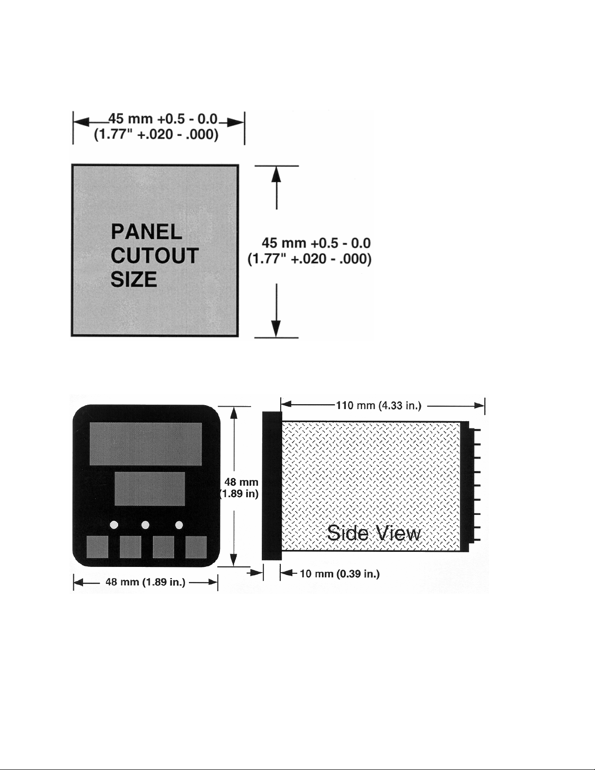
FIGURE 2-1
Panel Cut-Out Dimensions
FIGURE 2-2
Main Dimensions
4
Page 9
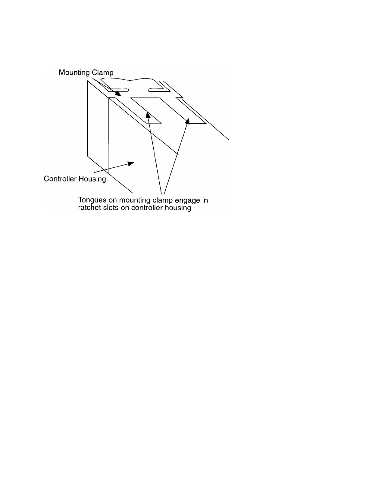
FIGURE 2-3
Panel Mounting the Controller
2.2 Wiring Guidelines
Electrical noise is a phenomenon typical of industrial environments. The following are
guidelines that must be followed to minimize the effect of noise upon any
instrumentation.
2.2.1 Installation Considerations
Listed below are some of the common sources of electrical noise in the
industrial environment:
• Ignition Transformers
• Arc Welders
• Mechanical contact relay(s)
• Solenoids
Before using any instrument near the device listed, the instructions below
should be followed:
5
Page 10

1. If the instrument is to be mounted in the same panel as any of the listed devices,
separate them by the largest distance possible. For maximum electrical noise
reduction, the noise generating devices should be mounted in a separate enclosure.
2. If possible, eliminate mechanical contact relay(s) and replace with solid state relays.
If a mechanical relay being powered by an instrument output device cannot be
replaced, a solid state relay can be used to isolate the instrument.
3. A separate isolation transformer to feed only instrumentation should be considered.
The transformer can isolate the instrument from noise found on the AC power input.
4. If the instrument is being installed on existing equipment, the wiring in the area
should be checked to insure that good wiring practices have been followed.
2.2.2 AC Power Wiring
Neutral (For 115 VAC)
It is good practice to assure that the AC neutral is at or near ground potential. To verify
this, a voltmeter check between neutral and ground should be done. On the AC range,
the reading should not be more than 50 millivolts. If it is greater than this amount, the
secondary of this AC transformer supplying the instrument should be checked by an
electrician. A proper neutral will help ensure maximum performance from the
instrument.
2.2.3 Wire Isolation
Three voltage levels of input and output wiring may be used with the unit:
• Analog input or output (i.e. thermocouple, RTD, VDC, mVDC, or mADC)
• SPDT Relays
• AC power
The only wires that should run together are those of the same category. If they need to
be run parallel with any of the other lines, maintain a minimum 6 inch space between
the wires. If wires must cross each other, do so at 90 degrees. This will minimize the
contact with each other and reduces "cross talk". "Cross Talk" is due to the EMF
(Electro-Magnetic Flux) emitted by a wire as current passes through it. This EMF can
be picked up by other wires running in the same bundle or conduit.
In applications where a High Voltage Transformer is used (i.e. ignition systems) the
secondary of the transformer should be isolated from all other cables.
6
Page 11

This instrument has been designed to operate in noisy environments, however, in some
cases even with proper wiring it may be necessary to suppress the noise at its source.
2.2.4 Use Of Shielded Cable
Shielded cable helps eliminate electrical noise being induced on the wires. All analog
signals should be run with shielded cable. Connection lead length should be kept as
short as possible, keeping the wires protected by the shielding. The shield should be
grounded at one end only. The preferred grounding location is the sensor, transmitter
or transducer.
2.2.5 Noise Suppression At The Source
Usually when good wiring practices are followed no further noise protection is
necessary. Sometimes in severe electrical environments, the amount of noise is so
great that it has to be suppressed at the source. Many manufacturers of relays,
contactors, etc. supply “surge suppressors" which mount on the noise source.
For those devices that do not have surge suppressors supplied, RC (resistancecapacitance) networks and/or MOV (metal oxide varistors) may be added.
Inductive Coils - MOV's are recommended for transient suppression in inductive coils
connected in parallel and as close as possible to the coil. See Figure 2-4. Additional
protection may be provided by adding an'RC network across the MOV.
7
Page 12
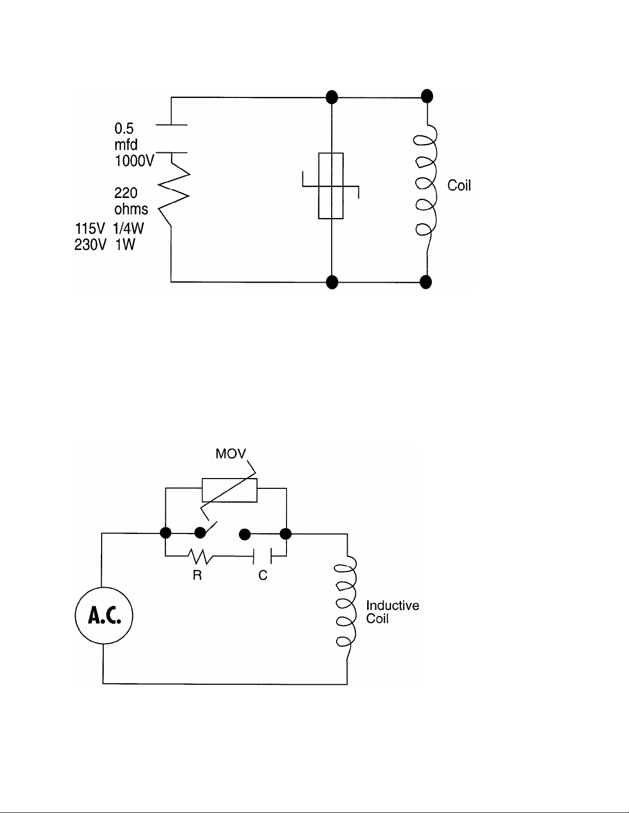
FIGURE 2-4
Contacts - Arcing may occur across contacts when the contact opens and closes. This
results in electrical noise as well as damage to the contacts. Connecting a RC network
properly sized can eliminate this arc.
For circuits up to 3 amps, a combination of a 47 ohm resistor and 0.1 microfarad
capacitor (1 000 volts) is recommended. For circuits from 3 to 5 amps, connect 2 of
these in parallel. See Figure 2-5.
FIGURE 2-5
8
Page 13
2.3 Sensor Placement (Thermocouple or RTD)
Two wire RTD's should be used only with lead lengths less than 10 feet.
If the temperature probe is to be subjected to corrosive or abrasive conditions, it should
be protected by the appropriate thermowell. The probe should be positioned to reflect
true process temperature:
In liquid media - the most agitated area
In air - the best circulated area
FIGURE 2-6
Wiring Label
9
Page 14
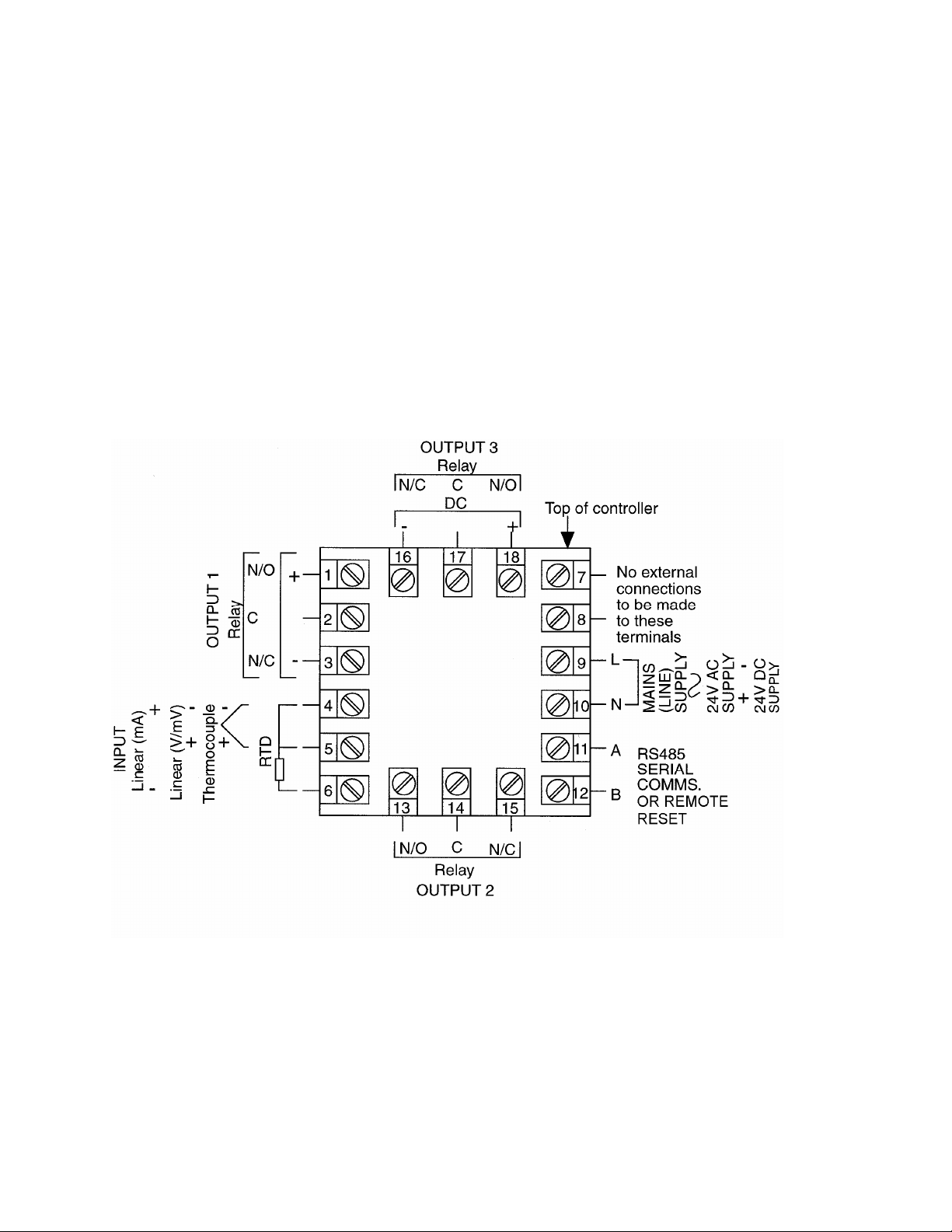
2.4 Input Connections
In general, all wiring connections are made to the instrument after it is installed. Avoid
electrical shock. AC power wiring must not be connected to the source distribution
panel until all wiring connection procedures are completed.
FIGURE 2-7A
Main Supply
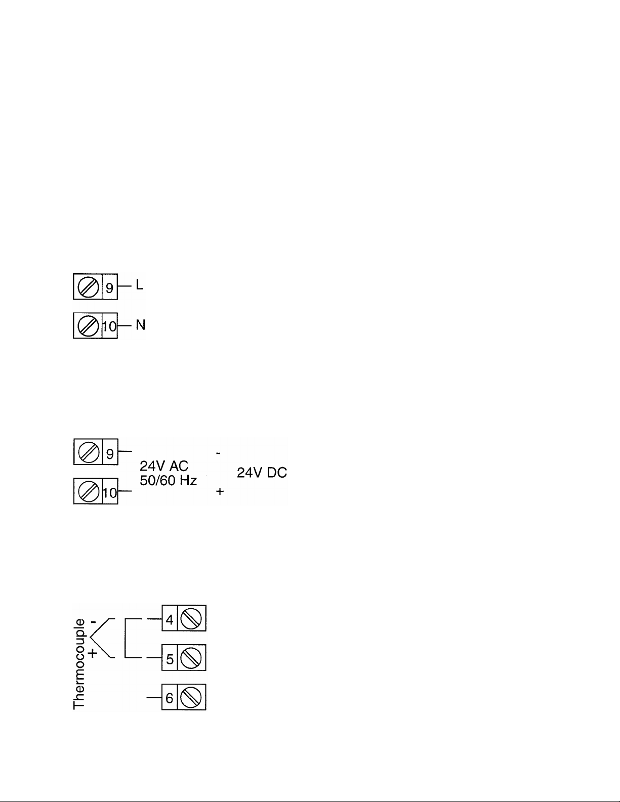
The instrument will operate on 90-264V AC 50/6OHz main supply. The power
consumption is approximately 4 VA. Connect the line voltage, hot and neutral, to
terminals 9 to 10 respectively as illustrated below.
FIGURE 2-7B
24V (Nominal) AC/DC Supply
The supply connections for the 24V AC/DC versions of the instrument are
shown below.
FIGURE 2-8
Thermocouple (T/C) Input
Make thermocouple connections as illustrated below. Connect the positive
leg of the thermocouple to terminal 5 and the negative leg to terminal 4.
FIGURE 2-9
10
Page 15
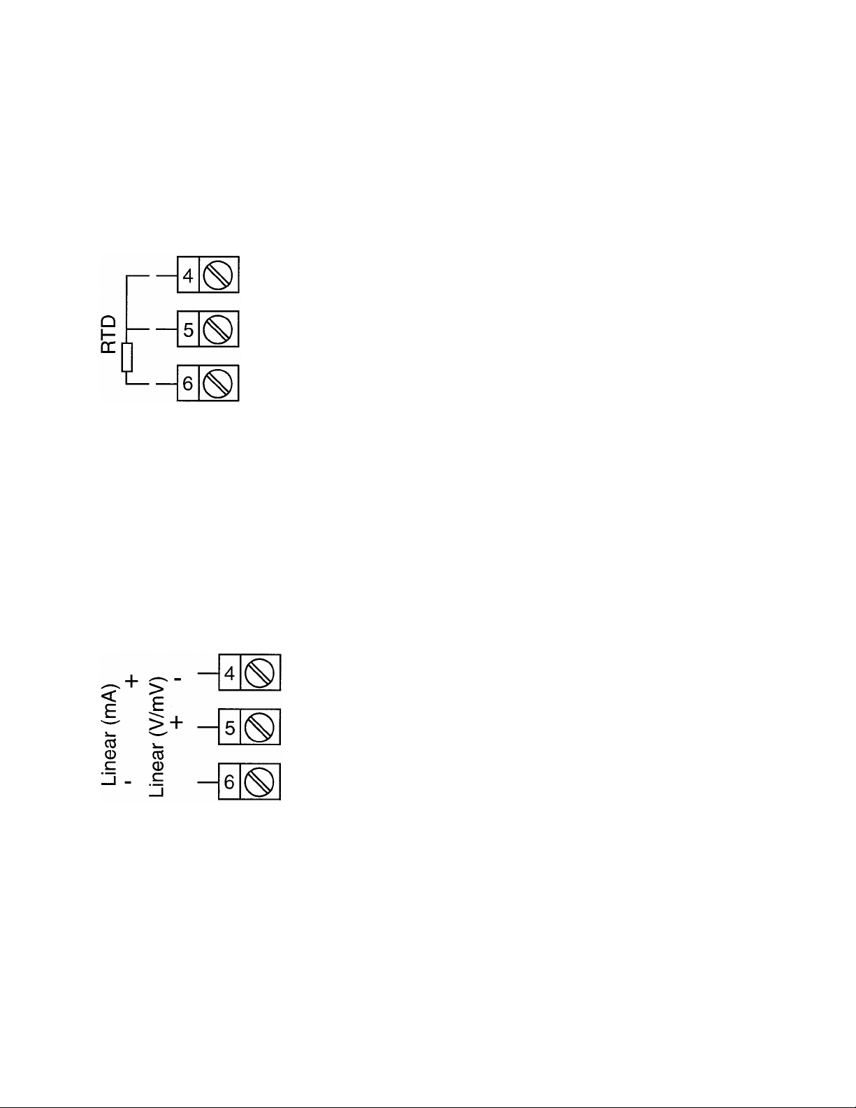
RTD Input
Make RTD connections as illustrated below. For a three wire RTD, connect the
resistive leg of the RTD to terminal 6 and the common legs to terminals 4 and 5. For a
two wire RTD, connect one leg to terminal 5 and the other leg to terminal 6 as shown
below. A jumper wire supplied by the customer must be installed between terminals 4
and 5. Input conditioning jumper must be positioned correctly (see Appendix A) and
Hardware Definition Code must be correct (see Appendix B).
FIGURE 2-10
Volt, mV Input
Make volt and millivolt connections as shown below. Terminal 5 is positive and terminal
4 is negative. Input conditioning jumper must be positioned correctly (see Appendix A)
and Hardware Definition Code must be correct (see Appendix B).
mADC Input
Make mADC connections as shown below. Terminal 4 is positive and terminal 6 is
negative. Input conditioning jumper must be positioned correctly (see Appendix A) and
Hardware Definition Code must be correct (see Appendix B).
11
Page 16

FIGURE 2-11
Remote Digital Communications - RS485
Make digital communication connections as illustrated below.
FIGURE 2-12
Remote Reset
Connections are made as illustrated below for remote reset.
12
Page 17

2.5 Output Connections
FIGURE 2-13
Relay Output 1
Connections are made to Output 1 relay as illustrated below. The contacts are rated at
5 amp resistive, 120/240 VAC.
FIGURE 2-14
Relay Output 2 (Alarm or Annunciator)
Connections are made to Output 2 relay as illustrated below. The contacts
are rated at 2 amp resistive, 120/240 VAC.
FIGURE 2-15
Relay Output 3 (Alarm or Annunciator)
Connections are made to Output 3 relay as illustrated below. The contacts are rated at
2 amp resistive, 120/240 VAC.
13
Page 18

FIGURE 2-16
mADC Output 3 (Recorder Output Only)
Make connections for DC output 3 as illustrated below.
14
Page 19

SECTION 3: OPERATION
3.1 Power Up Procedure
Verify all electrical connections have been properly made before applying power to the
instrument.
During power up, a self-test procedure is initiated during which all LED segments in the
two front panel displays appear and all LED indicators are ON. When the self-test
procedure is complete, the instrument reverts to normal operation.
Note: When power is first applied, a delay of about 3 seconds will be seen before the
LEDs will light.
3.2 Keypad Operation
RESET KEY
This key is used to:
1. Reset the limit condition after the process is within the limit
2. Acknowledge that the limit has been exceeded
3. Confirm entry in Configuration Mode
SCROLL KEY
This key is used to:
1. Select a parameter to be viewed or adjusted.
2. Display enabled modes of operation.
3. Display a mode parameter value.
4. Advance display from a parameter value to the next parameter code.
5. With the DOWN key to view the current Hardware Definition Code setting.
UP KEY
This key is used to:
1. Increase the displayed parameter value.
2. Increase setpoint.
3. Reset MAX/MIN HOLD and TIME EXCEED.
DOWN KEY
This key is used to:
1. Decrease the displayed parameter value.
2. Decrease setpoint.
3. Reset MAX/MIN HOLD and TIME EXCEED.
4. With the SCROLL key to view the current Hardware Definition Code setting.
15
Page 20

3.3 Displays
During configuration the upper display shows the parameter setting. The lower display
shows the parameter code (tag name) for the currently selected parameter. During
operation, the upper display shows the value of the process variable. The lower display
shows the setpoint value. The operation display can be altered by the Display
parameter in the Setup mode.
3.3.1 Alarm Status Display
The user may view the status of the instrument's alarm(s) by depressing the SCROLL
key until the lower display shows the legend "ALSt" and the upper display shows the
alarm status in the following format:
NOTE: This display is available only if one or more of the alarms is/are active.
3.3.2 Over-Range/Under-Range Display
If the process variable attains a value higher than the input scale maximum
limit, the upper display will show:
16
Page 21

If the process variable attains a value lower than the input scale minimum, the upper
display will show:
If a break is detected in the sensor circuit, the upper display will show:
3.4 Front Panel Indicators
OUT Indicates the status of the Limit Relay. When the indicator is on, the relay is de-
energized, and when off, the relay is energized.
EXCEED This indicator is on when the process variable exceeds the limit setpoint
(above for high limit, below for low limit). The indicator flashes if the error is not
acknowledged (i.e. Reset key is not pressed). The indicator is on steady if the
error has been acknowledged (i.e. Reset key has been pressed). Note: This
LED action will occur even if the annunciator output is NOT selected in
configuration.
ALM This indicator shows an alarm condition.
S Indicates when in Set-Up mode.
3.5 Exceeding Limit Setpoint
If the process value exceeds the limit setpoint, the limit relay will change state and
latch. This is noted by the OUT indicator. The EXCEED indicator will also flash.
To acknowledge the limit condition, press the RESET key. If the process value
exceeds the limit setpoint, the EXCEED indicator will change to a steady on condition.
The EXCEED indicator will turn off once the process value no longer exceeds the limit
setpoint.
In order to reset the limit relay, the process value must not exceed the limit setpoint.
Pressing the RESET key with the control in this state will reset the limit relay, and the
OUT indicator will turn off.
17
Page 22

NOTE: The hysteresis limit value in the setup mode affects the value at which the
control will reset. In the event of a high limit condition, the high limit setpoint must be
higher than the sum of the process value and the hysteresis value. In the event of a
low limit condition, the process value must be higher than the sum of the low limit
setpoint and the hysteresis value.
3.6 Annunciator
An additional (optional) annunciator output is available. If selected in Program mode
(either for USE2 or USE3) the annunciator output operates as follows:
If the limit is, or has been, exceeded AND the Reset key has NOT been pressed since
the limit was exceeded, then the annunciator output will be active.
If the Reset key is pressed while the limit is exceeded, the annunciator output will be
deactivated, even if the limit remains being exceeded.
3.7 Remote Reset (Optional)
The Remote Reset option allows a dry contact closure to substitute for the front panel
Reset switch. Operation is as follows:
If the option “rrES” (remote reset) is selected then:
A contact closure will simulate the action of the front panel reset switch.
A contact opening will have no effect.
If the external contacts are left closed, only ONE reset operation will occur. If the
instrument subsequently goes into a state where reset is required again, the contacts
must be opened and closed again. The front panel Reset switch can still be used to
activate a reset if required.
18
Page 23

SECTION 4: CONTROL MODE
The Control mode allows viewing of the control status and process variables. Other
modes can be accessed by pressing the SCROLL key until the appropriate mode is
displayed, then pressing the DOWN key.
CONTROL SETPOINT
CHANGE
(Ctrl) (SPC) (ConF) (SEt)
If a mode is not enabled it will be skipped over by the routine.
The Setpoint Change mode is used to adjust the limit setpoint(s).
The Configuration mode is used to configure or re-configure the instrument. The input
and output selections are made in the Configuration mode (see Section 6). All possible
parameters are illustrated in Table 6-1. Only those parameters that are applicable to
the hardware options chosen will be displayed.
The Set-Up mode is used to adjust the displays, make alarm settings and retransmit
scaling as needed for proper operation of the instrument. See Section 7 for the Set-up
mode. Only those parameters that are applicable will be displayed.
The Enable mode provides a means of enabling or disabling access to the Program
and Set-Up modes, and enables the Setpoint Change parameter. See Section 8 for
Enable Mode operation.
CONFIGURATION SET-UP
19
Page 24

SEt
HiH
d
LoH
d
tLE
iCo
r
Fil
t
Hys
t
PoU
PoL
PHA
1
PLA
1
PHA
2
PLA
2
dPo
S
Euu
EuL
CCo
n
diS
P
Con
F
inP
S
ACt
SPU
L
SPL
L
ALA
1
ALA
2
USE
2
USE
3
CbS
CPA
r
CAd
CJC
Returnt
o
maindisplay
CtrlSPC
S
P
SPH
i
SPL
o
o
r
PressUPkeywit
h
upperdisplayblank
toexitmode.
InConfigurationMode
,
theRESETkeymust
bepressedtostor
e
anychangedvalues.
=SCROLLke
y
=DOWNke
y
20
Page 25

SECTION 5: SETPOINT CHANGE MODE
To change the limit setpoint, the Setpoint Change Mode must be enabled (see Enable
Mode). From the Control Mode, press the SCROLL key until SPC is displayed. Press
the DOWN key to access Setpoint Change Mode.
To change the high limit setpoint, press the DOWN key until SPHi* is displayed in the
lower display with the upper display blank. Press the SCROLL key and the current
setpoint will be shown in the upper display. Use the UP and DOWN keys to adjust the
setpoint. Press the SCROLL key.
To change the low limit setpoint, press the DOWN key until SPLo* is displayed in the
lower display with the upper display blank. Press the SCROLL key and the current
setpoint will be shown in the upper display. Use the UP and DOWN keys to adjust the
setpoint. Press the SCROLL key.
To return to Control Mode, press the UP key when the upper display is blank. The
control will accept the new setpoint(s) at this time.
The lower display will read SPC. Press the SCROLL key until Ctrl is displayed. Press
the DOWN key.
If no keys are pressed within 20 seconds while in Setpoint Mode, the instrument will
time out and return to Control Mode automatically.
NOTE: The instrument will not accept the new setpoint if the Setpoint Change Mode is
allowed to time out.
* SP will be displayed if the instrument has been configured as either a high limit
or a low limit control, but not both.
21
Page 26

SECTION 6: CONFIGURATION
All configurable parameters are provided in Table 6-1. This table illustrates the display
sequence, parameter adjustment and factory setting for each step.
Depression of the SCROLL key will cycle the display.
To enter the Configuration mode, press and release the SCROLL key until ConF is
displayed. Use the DOWN key to enter the Configuration mode. Depress and release
the SCROLL key to sequence through the parameters and their values, alternately
showing the parameter code in the lower display with the upper display blank, then the
parameter code with the parameter value in the upper display. Use the UP and DOWN
keys to adjust the parameter values.
After adjusting a parameter, the upper display will flash, indicating that the new setting
has yet to be confirmed. When the setting is as required, it may be confirmed by
pressing the RESET key, and the upper display will stop flashing. After confirming a
change, press the SCROLL key to proceed to the next parameter.
The DOWN key may also be used to advance to the next parameter when a parameter
code is showing in the lower display and the upper display is blank. This is a faster way
of scrolling through the parameter list.
To exit the Configuration mode, press the UP key whenever a parameter code is
displayed in the lower display and the upper display is blank. The instrument will
automatically exit the Configuration mode if no key is pressed in one minute.
DEFAULT PARAMETER INDICATION
If a parameter value, such as Input Select, was changed while in the Configuration
mode, a decimal point after each digit will be lit when returning to the Control mode.
This display indicates all Setup mode parameters have been set to their default
condition. To clear this condition, enter the Setup mode and make a parameter value
change and review each parameter for its proper setting.
22
Page 27

Table 6-1 Configuration Mode Parameters
STEP DESCRIPTION DISPLAY
CODE
1 Input Range
Select
2 Limit Action ACt Hi/Lo/Both Hi
3 Limit Maximum SPUL +/- SPAN Span max.
4 Limit Minimum SPLL +/- SPAN Span min.
5 Alarm 1 Type ALA1 nonE = No Alarm
6 Alarm 2 Type ALA2 Same selection as ALA1 P_hi
7 Output 2 Usage2 USE2 AL_d = Alm1 Direct
8 Output 3 Usage2 USE3 Al-d =Alm Dir
9 Com Bit Rate3 CbS 1200, 2400, 4800, 9600 4800
10 Com Parity3 CPAr nonE, EvEn, odd nonE
11 Com Address3 CAd 1 - 32 1
12 CJC Enable CJC EnAb
1 Does not appear unless Output 3 is configured as 4-20 mA.
2 Does not appear unless additional output has been selected.
3 Does not appear unless communications option has been selected.
inPS See App. C* 1420
AVAILABLE SETTINGS FACTORY
SETTING
P_hi
P_hi = Process High
P_Lo = Process Low
LiHi = High Limit
LiLo = Low Limit
Al_d
LA_r = Annunc. Reverse
LA_d = Annunc. Direct
Ad_r =Rev Logic AND
Ad_d=Dir Logic AND
Or_r =Rev Logic OR
Or_d=Dir Logic OR
A2_r = Alm Rev
A2_d = Alm Dir
Al_r = Alm1 Rev
Al_d (rEcP
rEcP = Rcdr Out P.V.
LA_r = Annunc. Reverse
LA_d = Annunc. Direct
Ad_r = Rev Logic AND
Ad_d = Dir Logic AND
Or_r = Rev Logic OR
Or _d = Dir Logic OR
A2_r = Alm2Rev
A2_d = Alm2Dir
Al_r = Alm Rev
diSA
when output 3
is retransmit)
EnAb
*The Hardware Definition Code and input jumper configuration may need to be
changed. See Appendices A and B.
23
Page 28

LOGICAL COMBINATION OF ALARMS
Two alarms may be combined logically to create an AND/OR situation.
They may be configured for Reverse-acting or Direct-acting. Either Output
2 or Output 3 may be assigned as Logical Outputs.
Example:
Logical OR of Alarm 1 with Alarm 2
Direct-Acting Reverse-Acting
AL1 OFF, AL2 OFF: Relay OFF AL1 OFF, AL2 OFF: Relay ON
AL1 ON, AL2 OFF: Relay ON AL1 ON, AL2 OFF: Relay OFF
AL1 OFF, AL2 ON: Relay ON AL1 OFF, AL2 ON: Relay OFF
AL1 ON, AL2 ON: Relay ON AL1 ON, AL2 ON: Relay OFF
Example:
Logical AND of Alarm 1 with Alarm 2
Direct-Acting Reverse-Acting
AL1 OFF, AL2 OFF: Relay OFF AL1 OFF, AL2 OFF: Relay ON
AL1ON, AL2 OFF: Relay OFF AL1 ON, AL2 OFF: Relay ON
AL1 OFF, AL2 ON: Relay OFF AL1 OFF, AL2 ON: Relay ON
AL1 ON, AL2 ON: Relay ON AL1 ON, AL2 ON: Relay OFF
24
Page 29

SECTION 7: SET-UP MODE
To enter the Set-Up mode, press and release the SCROLL key until SEt is displayed.
Use the DOWN key to enter the Set-Up mode. The “S” LED will light. Depress and
release the SCROLL key to sequence through the parameters and their values,
alternately showing the parameter code in the lower display with the upper display
blank, then the parameter code with the parameter values in the upper display. Use the
UP and DOWN keys to adjust the parameter values. After adjusting a parameter,
depress the SCROLL key to proceed to the next parameter. The DOWN key may also
be used to advance to the next parameter when a parameter code is showing in the
lower display and the upper display is blank.
To exit the Set-Up mode, press the UP key whenever a parameter code is displayed in
the lower display and the upper display is blank.
Table 7-1 Set-Up Mode Parameters
STEP DESCRIPTION DISPLAY
CODE
1 Alarm Status3 ALSt Read Only
2 Maximum Hold HiHd Read Only
3 Minimum Hold LoHd Read Only
4 Time Exceeded tLE Read Only
5 Input Correction iCOR +/-Span 0
6 Input Filter Filt 0.0 to 100.0 seconds in
7 Hysteresis Limit HySt 0 to 10.0% of span 1
8 Process Output Upper Pou -1999 to 9999 Span Max.
9 Process Output Lower PoL - 1999 to 9999 Span. Min.
10 Process High Alarm 11 PHA1 ± Span Span Max.
11 Process Low Alarm 11 PLA1 ± Span Span Min.
12 Process High Alarm 21 PHA2 ± Span Span Max.
13 Process Low Alarm 21 PLA2 ± Span Span Min.
14 Decimal Position dPoS 0, 1, 2, 3 1
15 Engineering Units 2
Upper
16 Engineering Units 2
Lower
17 Comm. Enable CCon O=Disable
Euu -1999 to 9999 1000
EuL - 1999 to 9999 0
AVAILABLE SETTINGS FACTORY
SETTING
2.0
.5 sec. Increments
1
1 =Enable
25
Page 30

STEP DESCRIPTION DISPLAY
CODE
18 Display Enable diSP 1 = Display Setpoint*
1
Applies only if process alarm is selected in Configuration mode.
2
Applies only if a linear input has been specified.
3
Only if an alarm is active.
AVAILABLE SETTINGS FACTORY
SETTING
3
2 = Display Process
Variable
3 = Display Process
Variable** and Setpoint
4 = Display Blank
* If configured for both
high and low limit ,the
high limit setpoint will be
in the upper display and
the low limit in the lower
display.
** If configured for both
high and low limit,
pressing the up key
while in control mode
will display high limit
setpoint. Pressing the
down key will display the
low limit setpoint.
NOTE: Euu and EuL parameters can not be adjusted within the range of the SPhi and
SPlo parameters of the Setpoint Change Mode. SPhi and SPlo may need to be
changed before properly setting Euu and EuL.
MAXIMUM/MINIMUM HOLD
A parameter is available that tracks and saves the maximum (high limit) or minimum
(low limit) excursions of the process variable.
This parameter is a read only parameter and is viewed in the Set-Up mode, display
code HiHd (maximum hold) and LoHd (minimum hold).
To reset this parameter, select the parameter and with the numeric value in the upper
display, press and hold the UP or DOWN keys. After about 5 seconds, the upper
display will indicate ---- for about another 2 seconds, then change to 0.00. Release the
key.
The value will be held through a supply power down/power up cycle.
26
Page 31

TIME EXCEED
This parameter is available to measure the amount of time that the limit is exceeded.
This parameter is a read only parameter and is viewed in the Set-Up mode, display
code tLE.
The parameter will time in minutes and seconds from 0 to 99 minutes and 59 seconds.
After this time the display will change automatically to indicate minutes and tens of
seconds from 100.0 to 999.5. For times greater than 999.5 the display will be HH.
The value viewed is the cumulative time that the instrument has been out of limit.
To reset this parameter, select the parameter and with the numeric value in the upper
display, press and hold the UP or DOWN keys. After about 5 seconds, the upper
display will indicate ---- for another 2 seconds, then change to 0.00. Release the key.
The value will be held through a supply power down/power up cycle.
27
Page 32

SECTION 8: ENABLE MODE
To enter the Enable mode, press and hold the SCROLL key. The display flashes for
about 5 seconds, then returns to a normal display for about 5 more seconds, then
displays EnAb. Release the keys, the display should show ESP. Pressing the DOWN
key will display the Enable mode codes in the following sequence:
ESP – ECon – ESEt
Pressing the SCROLL key will display the Enable mode codes with the upper display
blank. The next depression of the SCROLL key will add the Enable code status (ON or
OFF) to the upper display. With the Enable code status displayed, use the UP key to
change the status to ON and the DOWN key to change the status to OFF.
To exit the Enable mode, press the UP key with any Enable mode code displayed in the
lower display and the upper display blank. The control will automatically return to
Control mode if no key is pressed within one minute.
Table 8-1 Enable Mode Parameters
STEP DESCRIPTION DISPLAY CODE AVAILABLE
SETTINGS
1 Setpoint Mode ESP ON/OFF ON
2 Configuration Mode ECon ON/OFF ON
3 Set-Up Mode ESEt ON/OFF ON
FACTORY
SETTING
28
Page 33

SECTION 9: CALIBRATION
NOTE: Calibration should be attempted only on instruments on which calibration errors
have been encountered (see calibration check).
EQUIPMENT REQUIRED:
1. Input source with accuracy better than +/- 0.05% of reading.
a. Thermocouple: T/C simulator, K type with compensated leads
b. DC: 0 to 50 mV OR
0 to 10 V OR
0 to 20 mA
c. RTD: Decade resistance box with 3 wire input
2. MIC1162 case wired for appropriate input voltage supply (90 to 264 VAC, 50/60
Hz)
PROCEDURE:
1. Before applying power, position the input conditioning jumpers on the CPU PWA
as appropriate. See Figure A-1 and A-2 in Appendix A.
2. Connect the appropriate input from the Input Source. Set the Input Source as
follows:
INPUT TYPE
DC 0 - 50 mV 50 mVDC
DC 0 - 10 V
DC 0 - 20 mA 20 mADC
RTD
T/C (Type K)
INPUT SOURCE
10 VDC
200 ohms
0° C
3. Apply power to the instrument and leave powered for five (5) minutes for RTD
and DC inputs OR thirty (30) minutes for T/C inputs, then power down.
29
Page 34

4. Apply power to the instrument and within 30 seconds of power-up, press and
hold the DOWN and SCROLL keys simultaneously for about 5 seconds. The
upper display will show ip_1 and the lower display will show CAL.
5. Use the UP/DOWN keys as required to change the input type number as
required:
CAL INPUT NO. INPUT TYPE
1
2
3
4
5
DC 0 - 50 mv
DC 0 - 10 V
DC 0 - 20 mA
RTD
Thermocouple
NOTE: If required, only one input type may be calibrated. EXCEPTION: If it is required
to calibrate the thermocouple input (Input Type 5), it is necessary to calibrate the DC 0 50 mV (Input Type 1) first.
6. Press the RESET key, the upper display will show _ _ _ _.
7. After a few seconds, the upper display will show ip_X, where X is the CAL INPUT
No., if the calibration was successful. If the upper display shows FAIL, the
calibration was not successful - check the jumper positions, wiring, CAL INPUT
No. and try again.
8. To calibrate all inputs, repeat steps 2 through 7 for each of the other input types.
9. The calibration procedure is now complete. Disconnect power, remove input
connections.
30
Page 35

CALIBRATION CHECK
(See Configuration Mode, Appendix A, and Appendix B.)
1. Power up the instrument and allow to stabilize for at least 5 minutes (RTD and
DC) or 30 minutes for T/C input.
2. After the stabilization period, connect the appropriate input device and check a
number of input points.
31
Page 36

APPENDIX A: BOARD LAYOUT - JUMPER POSITIONING
FIGURE A-1 Exploded View & Board Layout
32
Page 37

FIGURE A-2 CPU PWA
33
Page 38

FIGURE A-3 OPTION PWA DC OUTPUT 2/OUTPUT 3
34
Page 39

APPENDIX B: HARDWARE DEFINITION CODE
The Hardware Definition Code is used to represent the hardware installed (input type,
Output 2 type and Output 3 type); this must be compatible with the hardware actually
installed. It can be accessed, with the instrument in Configuration mode, by
simultaneously depressing the DOWN and SCROLL keys. The displays will show
XXXX (where X represents any number) in the upper display and dEFn in the lower
display, where:
the first (left-most) digit is input type:
1 =RTD/Linear mV
2=Thermocouple
3=Linear DC mA
4=Linear DC V
the second digit is Output 1 type:
1=Relay
the third digit is Output 2 type:
0=Output 2 not installed
1 =Relay (Alarm Only)
the fourth digit is Output 3 type:
O=Output 3 not installed
1 =Relay (Alarm 1 only)
2=SSR (not available)
3=DC 0-10V (retransmit only)
4=DC 0-20mA (retransmit only)
5=DC 0-5V (retransmit only)
7=DC 4-2OmA (retransmit only)
The displayed code may be incremented/decremented using the UP/ DOWN keys as
required. The maximum setting available is 4117. For example, the code for a
thermocouple input, Relay Output 1 and Relay Output 3 would be 2101. When the
code is first altered, the code display will flash, until the desired value is displayed and
confirmed by pressing the Reset key.
35
Page 40

While the Hardware Definition Code is displayed, depressing the SCROLL key will
cause the display to change to:
nonE or r485 or rrES
OPtn OPtn OPtn
Where none indicates the absence of the communications option and the remote reset
option, r485 indicates the presence of the communications option, and rrES indicates
the presence of the remote reset option.
The code may be changed by pressing the UP and DOWN keys. The RESET key must
be pressed when the correct code is displayed.
NOTE: It is essential that this code is changed whenever there is a change to the
instrument's hardware configuration (change of input/output type,
alarm/retransmit output added/removed etc.). The instrument's software
depends upon this code to ensure that the instrument operates correctly.
To exit from the Hardware Definition Code display, depress the DOWN and SCROLL
keys simultaneously.
36
Page 41

APPENDIX C: INPUT RANGE CODES
The input ranges available (selectable via the front panel) are:
TYPE INPUT RANGE DISPLAYED
CODE
R 0 - 1650°C 1127
R 32 - 3002°F 1128
S 0 - 1649°C 1227
S 32 - 3000°F 1228
J 0.0 - 205.4°C 1415
J 32.0 - 401.7°F 1416
J 0 - 450°C 1417
J 32-842°F 1418
J 0 - 761°C 1419
J 32 - 1401 °F 1420*
T -200 - 262°C 1525
T -328 - 503°F 1526
T 0.0 - 260.6°C 1541
T 32.0 - 501.O°F 1542
K -200 - 760°C 6726
* Factory default
For RTD Inputs
Note: Input conditioning jumper JU1 needs to be changed, see Appendix A. Also, the
Hardware Definition Code for the input type must be changed, see Appendix B.
INPUT RANGE DISPLAYED CODE
0 - 800°C 7220
32-1471°F 7221
32-572°F 2229
-101.0-100.0°C 2230
-149.8-212.0°F 2231
0-300°C 2251
For DC Inputs
Note: Input conditioning jumper JU1 needs to be changed, see Appendix A. Also, the
Hardware Definition Code for the input type must be changed, see Appendix B.
INPUT RANGE DISPLAYED CODE
0-2OmA 3413
4-2OmA 3414
0-5OmV 4443
10-5OmV 4499
TYPE INPUT RANGE DISPLAYED
CODE
K -328 -1400ºF 6727
K -200 - 1373ºC 6709
K -328 - 2503ºF 6710
L 0.0-205.7ºC 1815
L 32.0-402.3ºF 1816
L 0-450ºC 1817
L 32.0-842ºF 1818
L 0-762ºC 1819
L 32-1404ºF 1820
B 212-3315ºF 1934
B 100-1824ºC 1938
N 0 - 1399ºC 5371
N 32 - 2550ºF 5324
INPUT RANGE DISPLAYED CODE
0.0-100.9°C 2295
32.0-213.6°F 2296
-200-206°C 2297
-328-403°F 2298
-101.0-537.3°C 7222
-149.8-999.1°F 7223
INPUT RANGE DISPLAYED CODE
0-5V 4445
1-5V 4434
0-10V 4446
2-10V 4450
37
Page 42

APPENDIX D: SPECIFICATIONS
INPUT SPECIFICATIONS
General
Input Sample Rate: Four per second
Input Resolution: 14 bits approximately
Input Impedance: Greater than 100M ohm resistive (except for DC mA
and V inputs)
Isolation: Universal input isolated from all outputs except SSR at
240 VAC.
Thermocouple
Types: R, S, J, T, K, L, B and N
Calibration: Complies with BS4937, NBS125 and IEC584.
Sensor Break Protection: Break detected within 2 seconds. Limit Relay set to
OFF; alarms operate as if the process variable has
gone over-range.
RTD and DC mV
Type and Connection: Three-wire Pt100
Calibration: Complies with BS 1904 and DIN43760.
Lead Compensation: Automatic
Sensor Break Protection: Break detected within 2 seconds. Limit Relay set to
OFF (0% power); alarms operate as if the process
variable has gone under-range.
DC mA and DC V
Scale Range Maximum: -1999 to 9999
Scale Range Minimum: -1999 to 9999
Minimum Span: 1 display LSD
Sensor Break Protection: Applicable to 4-20mA, 1-5V, and 2-10V ranges only.
Break detected within 2 seconds. Limit Relay set to
OFF; alarms operate as if the process variable has
gone under-range.
Remote Reset
Type: Voltage-free contact, closure required to reset.
38
Page 43

OUTPUT SPECIFICATIONS
OUTPUT 1 (Limit Relay)
Relay
Contact Type: SPDT
Rating: 5A resistive at 120/240V AC
Lifetime: > 100,000 operations at rated voltage/current
Isolation: Inherent
OUTPUT 2 (Alarm or Annunciator)
Relay
Contact Type: SPDT
Rating: 2A resistive at 120/240V AC
Lifetime: > 500,000 operations at rated voltage/current
Isolation: Inherent
OUTPUT 3 (Alarm, Annunciator, or Retransmit)
General
Types Available: Relay or DC linear (retransmit only)
Relay
Contact Type: SPDT
Rating: 2A resistive at 120/240V AC
Lifetime: > 500,000 operations at rated voltage/current
Isolation: Inherent
DC
Resolution: Eight bits in 250mS (10 bits in 1 second typical, >10 bits in >1 second
typical).
Update Rate: 4 per second
Ranges: 0-20mA, 4-20mA, 0-10V, and 0-5V*
Load Impedance: 0-20mA: 500 ohm maximum
4-20mA: 500 ohm maximum
0- 10V: 500 ohm minimum
0-5V: 500 ohm minimum
Isolation: Isolated from all other inputs and outputs.
* Changes between V and mA ranges also require jumper movement.
39
Page 44

Alarms
Maximum Number: Two "soft" alarms
Maximum # Outputs: Up to 2 outputs can be used for alarm purposes
Combination Alarms: Logical OR or AND of alarms to an individual hardware output is
available.
PERFORMANCE
Reference Conditions
Ambient Temperature: 20ºC ± 2ºC
Relative Humidity: 60-70%
Supply Voltage: 90-264V AC 50Hz ±1%
Source Resistance: <10 ohm for T/C input
Lead Resistance: <0.1 ohm/lead balanced (Pt100)
Common Mode >120dB at 50/60Hz giving negligible effect at up to
Rejection 264V 50/60Hz
Series Mode >500% of span (at 50/6OHz) causes negligible effect
Rejection:
DC Linear Inputs
Measurement
Accuracy: ± 0.25% of span ± -1 LSD
RTD/Thermocouple Inputs
Measurement
Accuracy: ± 0.25% of span ± -1 LSD
Note: Reduced performance with Type B T/C between 100-600º C
(212 - 1112º F)
Linearization
Better than ± 0.2º C any point, any 0.1º C range (± 0.05º C typical).
Better than ± 0.5º C any point, any 1º C range.
Cold Junction Better than ± 0.7ºC
Compensation:
40
Page 45

Operating Conditions
Ambient Operating
Temperature: 0 to 55ºC
Ambient Storage
Temperature: -20 to 80ºC
Relative Humidity: 20% - 95% non-condensing
Supply Voltage: 90 - 264 VAC 50/60 Hz
Source Resistance: 1000 ohm maximum (thermocouple)
Lead Resistance: 50 ohm per lead maximum balanced (Pt 100)
Temperature Stability: 0.01% of Span/ºC change in ambient
PHYSICAL
Dimensions: 1/16 DIN front panel (48mm x 48mm) 4.33 inches deep
Mounting: Plug-in with panel mounting fixing strap.
Panel cut-out 45mm x 45mm.
Terminals: Screw type (combination head)
Power Consumption: Approximately 4 watts
Weight: 8 ounces maximum
Front Panel Sealing: IP65/NEMA4
Display Character
Height: Top - .36", bottom -.28"
Agency Approvals: FM pending
41
Page 46

112
6
OUTPUT1
1Rela
y
OUTPUT2
0None
1Relay*
OUTPUT3
0None
1Rela
y
34-20mA**
OPTIONS
0None
1RS-485
2RemoteRese
t
SUFFI
X
BlankNone
02LineVoltage24VAC/DC
*Foralarmoutputonly
**Forretransmissiononly
APPENDIX E: ORDER MATRIX
42
Page 47

APPENDIX F: SOFTWARE REFERENCE SHEET
Hardware Definition Setting
HDW DEF
OPTION
Configuration Mode Setting
inPS
ACt
SPUL
SPLL
ALA1
ALA2
USE2
USE3
CbS
CPAr
CAd
CJC
Enable Mode Setting
ENAB
ESP
ECon
ESEt
43
Page 48

Setup Mode Setting
HiHd
LoHd
tLE
iCOR
Filt
Hyst
Pou
PoL
PHAI
PLAI
PHA2
PLA2
dPoS
Euu
EuL
CCon
diSP
Setpoint Change Mode Setting
SP
SPHi
SPLo
44
Page 49

45
Page 50

46
 Loading...