

Page 1
Instruction Manual for the
Despatch/Watlow 1500 Control
P/N 260786
Rev. 8/96
E-87
U.S. $45.00
Page 2

Notice
Users of this equipment must comply with operating procedures and training of
operation personnel as required by the Occupational Safety and Health Act (OSHA)
of 1970, Section 6 and relevant safety standards, as well as other safety rules and
regulations of state and local governments. Refer to the relevant safety standards
in OSHA and National Fire Protection Association (NFPA), section 86 of 1990.
Caution
Setup and maintenance of the equipment should be performed by qualified
personnel who are experienced in handling all facets of this type of system.
Improper setup and operation of this equipment could cause an explosion that may
result in equipment damage, personal injury or possible death.
Dear Customer,
Thank you for choosing Despatch Industries. We appreciate the
opportunity to work with you and to meet your heat processing
needs. We believe that you have selected the finest equipment
available in the heat processing industry.
At Despatch, our service does not end after the purchase and
delivery of our equipment. For this reason we have created the
Service Products Division within Despatch. The Service Products
Division features our Response Center for customer service. The
Response Center will direct and track your service call to ensure
satisfaction.
Whenever you need service or replacement parts, contact the
Response Center at 1-800-473-7373: FAX 612-781-5353.
Thank you for choosing Despatch.
Sincerely,
Despatch Industries
Copyright © October 24, 2001 by Despatch Industries
Page 3

PREFACE
This manual is your guide to the Watlow 1500 control. It is
organized to give you the information you need quickly and
easily.
The INTRODUCTION section provides an overview of the
control.
The THEORY OF OPERATION section details the function
and operation of the control.
The INSTRUCTIONS section provides directions on
unpacking, installing, operating and maintaining the control.
The APPENDIX section contains Special Instructions for
operating the control instrument and a Troubleshooting
Table.
An efficient way to learn about the control would be to
read the manual while working with the control. This will
give you practical hands-on experience with information in
the manual and the control.
While reading this manual, if a term or section of
information is not fully understood, look up that item in the
appropriate section to familiarize yourself with that item.
Then go back and reread that section again. Information
skipped, not understood or misunderstood could create the
possibility of operating the equipment in an unsafe manner.
This can cause damage to the oven or personnel, or reduce
the efficiency of the equipment.
NOTE:
Read the entire
INTRODUCTION and
THEORY OF OPERATION
before operating the control.
WARNING:
Failure to head warnings in
this instruction manual and
on the oven could result in
death, personal injury or
property damage.
Despatch/Watlow 1500 Control Instruction Manual Page i
Page 4

Page ii Despatch/Watlow 1500 Control Instruction Manual
Page 5

Table of Contents
PREFACE ............................................................i
Table of Contents .................................................iii
List of Figures ....................................................iv
List of Tables .....................................................iv
INTRODUCTION ..................................................... 1
INSTRUCTIONS ...................................................... 3
Operating ........................................................ 3
Watlow 1500 Control ............................................... 4
Manual Set Point Controller ....................................... 6
Guarded Access Programming ..................................... 8
Setting the Clock ............................................. 9
GA0001 and 0002 PID Tuning ................................. 10
GA0000 Alarms ............................................. 10
GA0006 Setting Options ...................................... 11
ECOSPHERE/16000 Series Guarded Access Chart ................ 12
LPB Series Guarded Access Chart .............................. 13
Profile Mode .................................................. 14
Change Data Mode ............................................ 14
Halt Conditions ................................................ 14
Blank Step ................................................... 15
Set Point Step ................................................. 15
Creating Files/Profiles .......................................... 16
Wait Steps ................................................... 20
Next Step .................................................... 21
Recycle Option ................................................ 21
Write Your Program ............................................ 22
WORKSHEETS ..................................................... 23
Programming Work Sheet .......................................... 23
Sample HAST Profile for LPB Chambers ............................ 24
Procedure for Programming HAST Profile ........................... 25
HAST Chamber Programming Instructions and Definitions .............. 31
Ecosphere Sample Program ...................................... 32
Ecosphere Sample Profile Worksheet .............................. 33
Clearing a Program ............................................ 34
Tuning/Programming Worksheet ..................................... 35
Guarded Access Chart .......................................... 35
Warm/Cold Start ................................................. 36
Changing the Position of a Switch ................................. 37
Despatch/Watlow 1500 Control Instruction Manual Page iii
Page 6

List of Figures
Figure 1 illustrates the Watlow 1500 installed on the Series 16000 environmental
chamber control panel. ............................................. 4
Figure 2 DIP Switch Location and Orientation .............................. 36
List of Tables
Table 1 Watlow 1500 Displays ........................................... 4
Table 2 Watlow 1500 Keys .............................................. 5
Table 3 Watlow 1500 LEDs ............................................. 5
Table 4 GA0001 and 0002 PID Tuning Parameters .......................... 10
Table 5 GA0000 Alarms ............................................... 10
Table 6 Setting Options ............................................... 11
Table 7 Set Point Step Programming Detail ................................ 19
Table 8 Wait Steps ................................................... 20
Table 9 Despatch Sample Program ...................................... 32
Table 10 DIP Switch Selection .......................................... 37
Page iv Despatch/Watlow 1500 Control Instruction Manual
Page 7

INTRODUCTION
This INTRODUCTION section provides an overview of the
Watlow 1500 controller. The microprocessor based
controller is capable of measuring, displaying and
controlling temperature and humidity from a variety of
inputs.
The controller is easy to use. Control functions, alarm
settings and other parameters are easily entered through
the front keypad. Limited data can be protected from
unauthorized changes with its guarded access mode
security system. Battery back-up protects against data
loss during AC power outages.
In this application the controller has been factory
configured to control temperature and humidity conditions
in your Despatch chamber. Under normal conditions, you
should not have to reprogram this controller. We have,
however, included reprogramming instructions in this
manual to help guide you through that process if it should
become necessary.
NOTE:
Your control has already
been configured at
Despatch. Use this manual
as a guide to typical settings.
CAUTION:
Before making changes to
your control, consult with
Despatch Industries Product
Service at 1-800-473-7373.
Despatch/Watlow 1500 Control Instruction Manual Page 1
Page 8

Page 2 Despatch/Watlow 1500 Control Instruction Manual
Page 9

INSTRUCTIONS
Operating
To start the controller, start the oven fans. When you
start the fans the following sequence will automatically
take place.
1. The controller will power up.
2. The controller MNTR DATA LED will light up and the
alarm indicator A1 will be flashing in the FUNCTION
display. Alarm A1 is an indication of power loss.
3. Clear the alarm by pressing the clear button on the
Watlow 1500.
4. The actual temperature and humidity will be shown in
the ACTUAL display located at the top of the control.
Press the SEL key to toggle between temperature
and humidity. Temperature will be displayed on
Channel 1. Humidity will be displayed on Channel 2.
NOTE:
Your control has already
been configured at
Despatch. Use this manual
as a guide to typical settings.
CAUTION:
Before making changes to
your control, consult with
Despatch Industries Product
Service at 1-800-473-7373.
Despatch/Watlow 1500 Control Instruction Manual Page 3
Page 10
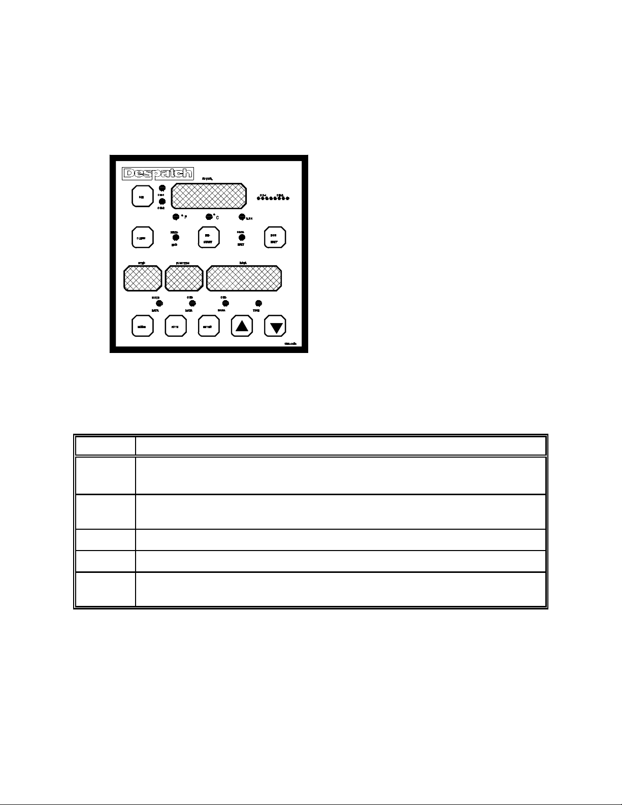
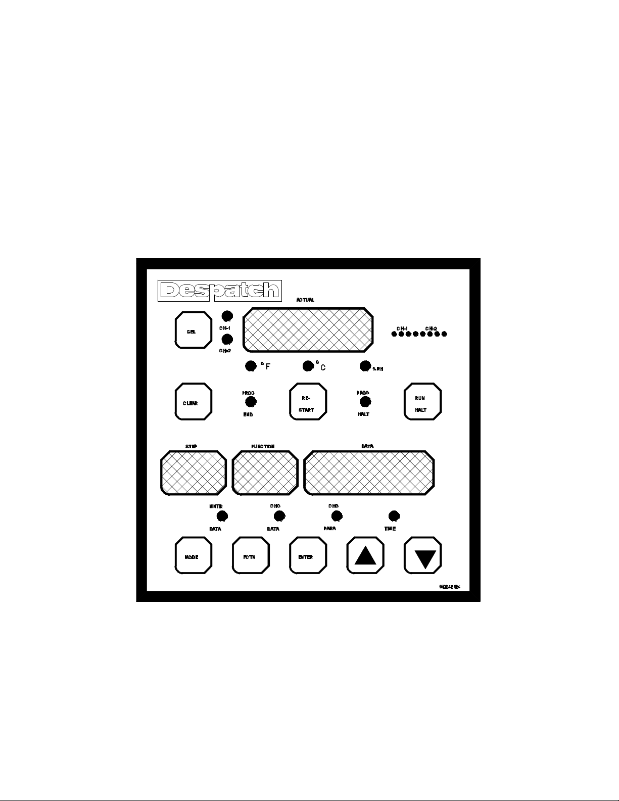
Watlow 1500 Control
The Watlow Series 1500 is a versatile microprocessorbased control; powerful, yet simple to learn.
Figure 1 illustrates the Watlow 1500 installed on the Series 16000
environmental chamber control panel.
Table 1 Watlow 1500 Displays
Display Description
Actual Shows the actual process conditions (dry bulb temp if CH-1 LED is on, RH% if
CH-2 is on.
Event Shows current status of all events. Lowest significant event is left justified
[instead of right justified as when events are shown in data display].
Step Shows which step the programmer is currently pointed to.
Function Describes the function or type of data being displayed in the data display.
Data Shows current value for the function being viewed. This display is effected by
the scroll up and down keys.
Page 4 Despatch/Watlow 1500 Control Instruction Manual
Page 11

Watlow 1500 Control (Cont.)
Table 2 Watlow 1500 Keys
Key Description
CH SEL Selects either channel 1 or channel 2 for the ACTUAL display.
CLEAR Clears alarm codes from the FUNCTION display in the monitor data mode.
Clears the step in the STEP display in the change data mode when the unit
is in the halt condition. Clears all 51 programmed steps when the unit is in
the halt condition, and in the guarded access area of the change parameter
mode.
RE-START Returns the controller to the initial program step only in the program halt
condition.
RUN/HALT Starts or stops the program. The processor will resume a program where it
was interrupted, unless the RESTART key was pressed, or the step number
or set point data at the current step was changed during the halt condition.
MODE Selects either the monitor data, change data or change parameter mode.
FCTN The FUNCTION key steps through the prompts in each of the three modes.
ENTER Enters the selected data or next step operations in the change data and
change parameter modes.
Increases and decreases the value in the DATA display. A light touch
changes the value by one. Holding the key down causes the DATA display
to increase rapidly.
Table 3 Watlow 1500 LEDs
LED Description
CH-1 CH-2 Indicates the channel in the ACTUAL display.
EEF Indicates the value in the ACTUAL display is temperature in EF.
EEC Indicates the value in the ACTUAL display is temperature in EC.
%RH Indicates the value in the ACTUAL display is per cent relative humidity.
PROG END Indicates that the processor has reached the end of the program.
PROG HALT Indicates that the processor is in the halt condition. This may be caused by
pressing the RUN/HALT key or by a blank step in the program. Flashing
indicates that the processor is in remote-hold condition.
MNTR
DATA
CHG DATA Indicates the processor is in the change data mode.
CHG PARA Indicates the processor is in the change parameter mode.
Indicates the processor is in the monitor data mode. While in this mode the
Watlow 1500 is used as a set point controller or a process profiler.
TIME Indicates that the FUNCTION and DATA displays are showing time.
Despatch/Watlow 1500 Control Instruction Manual Page 5
Page 12

Manual Set Point Controller
Use the following procedure to enter a dry bulb temperature,
RH%, or change auxiliary event status when the MNTR
DATA LED is on.
1. Press the RUN/HALT key so the PROG HALT LED
lights up.
2. Press the RESTART key.
3. Enter the dry bulb temperature.
a. Press the FCTN key until C1 is signaled in the
FUNCTION display.
b. Update the dry bulb temperature by using up/down
arrow keys.
c. Press enter when the desired set point is signaled in
the data display.
Your set point is now in effect.
If the set point shown in the DATA display is higher than
the value shown in the ACTUAL display for CH-1, then
the heat LED near the Watlow 1500 should be on.
If the set point in the DATA display is lower than the
value in the ACTUAL display for CH-1, then the cool
LED should be on.
Page 6 Despatch/Watlow 1500 Control Instruction Manual
Page 13

Manual Set Point Controller (Cont.)
4. Enter the %RH. The humidity event must be off when
outside of the range 4EC to 98EC. Humidity beyond
these extremes can result in equipment damage. If a
dry air system and an electronic humidity sensor are
installed in lieu of a wet bulb sensor, the optional dry
air event may be outside the range of 4EC to 98EC.
a. Press the FCTN key. C2 is shown.
b. Update the %RH temperature by using the up/down
keys.
c. Press enter when DATA display shows your desired
set point.
5. Change the auxiliary events.
a. Press the FCTN key. E1 is displayed.
b. Turn the auxiliary event on or off.
NOTE:
In the DATA display the right
most character for Event 11
is shown as 0001.
1 = on
0 = off
Try varying set points and events and watch how each
effects the output LEDs.
Despatch/Watlow 1500 Control Instruction Manual Page 7
Page 14

Guarded Access Programming
The Guarded Access parameters control the process limits.
the three GA parameter loops are restricted to operators by
special codes. The Guarded Access codes prevent
inexperienced or unauthorized operators from changing the
parameters.
You must select one of the following:
GA = 0000 To set CH-1 and CH-2 alarm limits
GA = 0001* To set CH-1 PID tune parameters
GA = 0002* To set CH-2 PID tune parameters
GA = 0006 To set set point scroll limits, optional
lockout and option recycle
*If GA = 0001 and 0002 will not work, try GA code 0005
for both channel parameters.
Use the following sequence to alter the GA prompts:
1. Follow the steps for “SETTING THE CLOCK.”
2. Select a GA code with the > key and the ? key.
3. Press ENTER. The prompt appears in the DATA
display.
4. Press the FCTN key. The next prompt in the loop
appears in the DATA display.
Page 8 Despatch/Watlow 1500 Control Instruction Manual
Page 15

Setting the Clock
1. Press the MODE key to select the Change Parameter
(CHG PARA) mode. The TIME LED will be ON. The
FUNCTION and DATA displays will show the real time
of day.
2. Press FCTN to produce the time prompt, HR, in the
FUNCTION display.
3. Enter the real time of day, beginning with hours. The
CHG PARA programming prompts are listed below in
the order they appear.
a. Enter the real time of day (24 hour basis) by
selecting the hour with the > key and the ? key.
b. Press ENTER to enter the hour into the program.
The prompt MN will appear when you press ENTER.
c. Select correct minutes and seconds.
After setting the real time the FUNCTION prompt should
display a GA. This is guarded access.
Despatch/Watlow 1500 Control Instruction Manual Page 9
Page 16

GA0001 and 0002 PID Tuning
Prompts appear for CH-1 with Code 0001, and then repeat
for CH-2 with Code 0002. Except for CA, these parameters
pertain directly to tuning your control to the system.
Table 4 GA0001 and 0002 PID Tuning Parameters
Parameter
Proportional
Band
Reset RS
Rate RT
Rate Band Rb Rate band defines where the rate function will occur. The
Cycle Time CT
Dead Band db The dead band defines an area on either side of set point
Calibration
Offset
FUNCTION
Display
Pb
rate band will occur at one to seven times the proportional
band. With a 0 entry, rate is always in effect.
where no switching action will occur.
CA Calibration offset enables you to offset the input value from
-10E to 10EC or EF.
Description
GA0000 Alarms
Prompts appear for CH-1, then repeat for CH-2. Refer to
the Watlow User's Manual for details.
Table 5 GA0000 Alarms
Parameters
Upper Process Type Alarm UP If you do not want this alarm, set to highest
Lower Process Type Alarm LP If you do not want this alarm, set to lowest value.
Upper Deviation Type
Alarm
Lower Deviation Type
Alarm
FUNCTION
Display
value.
Ud If you do not want this alarm, set to highest
value.
lD If you do not want this alarm, set to lowest value.
Description
Sequence repeats for Channel 2 and then leaves the
guarded area, returning to real time.
Page 10 Despatch/Watlow 1500 Control Instruction Manual
Page 17

GA0006 Setting Options
These parameters are high and low display and scroll limits,
and for some units, two channel control type and device
address.
Table 6 Setting Options
Parameter
FUNCTION
Display
CH-1 Upper Set Point Limit U1
CH-1 Lower Set Point Limit L1
CH-2 Upper Set Point Limit U2
CH-2 Low Set Point Limit L2
Front Panel Keyboard
LC Enter:
Lockout
C 1 to lock the entire front panel,
C 0 to unlock it.
Recycle RC Select:
C 1 to activate the recycle option (begin
again at Step #1 after completing a
profile),
C 0 to deactivate the recycle option.
Temp-Temp, 2-channel
temperature control
RS-422 Address for the
1500
TT This prompt will not appear on thermocou-
ple units. Select:
C 0000 for Temp-RH control
C 0001 or Temp-Temp control.
Ad This prompt appears only on units with data
communications. It applies only for an
RS-422 interface. Each device on the network must have its own address.
Description
Sequence then leaves the guarded area, returning to real
time.
Despatch/Watlow 1500 Control Instruction Manual Page 11
Page 18

ECOSPHERE/16000 Series Guarded Access Chart
Make a copy of this chart to document the Series 1500
Guarded Access for each program you use.
Program #_____ System _______ Programmer ________ Date__________
GA Code Ch Pmpt Parameter Typical ECOSPHERE Setting Your Settings
0000 C1 UP Ch-1 Upper Process Alarm 180
C1 LP Ch-1 Lower Process Alarm -75
C1 Ud Ch-1 Upper Deviation Alarm 538
C1 Ld Ch-1 Lower Deviation Alarm -538
C2 UP Ch-2 Upper Process Alarm 101
C2 LP Ch-2 Lower Process Alarm -001
C2 Ud Ch-2 Upper Deviation Alarm 101
C2 Ld Ch-2 Lower Deviation Alarm -101
0001 1 Pb Ch-1 Prop. Band 0009
1 RS Ch-1 Reset 0010
1 RT Ch-1 Rate 0000
1 Rb Ch-1 Rate Band 0001
1 CT Ch-1 Cycle Time 0003
1 db Ch-1 Dead Band 0001
1 CA Ch-1 Calibration Adjust. 0000
Dual
PID
0002 2 Pb Ch-2 Prop. Band 0020
Dual
PID
0006 U1 Ch-1 Upper Set Point Limit 177
1C Pb Ch-1 Prop. Band 0009
1C RS Ch-1 Reset 0002
1C RT Ch-1 Rate 0001
1C Rb Ch-1 Rate Band 0001
1C CT Ch-1 Cycle Time 0007
2 RS Ch-2 Reset 0010
2 RT Ch-2 Rate 0050
2 Rb Ch-2 Rate Band 0003
2 CT Ch-2 Cycle Time 0002
2 db Ch-2 Dead Band -0001
2 CA Ch-2 Calibration Adjust. 0000
2C Pb Ch-2 Prop. Band 0020
2C RS Ch-2 Reset 0006
2C RT Ch-2 Rate 0001
2C Rb Ch-2 Rate Band -0001
2C CT Ch-2 Cycle Time 0005
L1 Ch-1 Lower Set Point Limit -73
U2 Ch-2 Upper Set Point Limit 100
L2 Ch-2 Lower Set Point Limit 000
RC Recycle: ON = 1, OFF = 0 0
TT T-RH = 0000, T-T = 0001 0
Ad Address number RS-422 0
LC Keyboard Lock 0
Page 12 Despatch/Watlow 1500 Control Instruction Manual
Page 19

LPB Series Guarded Access Chart
Make a copy of this chart to document the Series 1500
Guarded Access for each program you use.
Program #_____ System _______ Programmer ________ Date__________
GA Code Ch Pmpt Parameter Typical HASP Settings Your Settings
0000 C1 UP Ch-1 Upper Process Alarm 170
C1 LP Ch-1 Lower Process Alarm 0
C1 Ud Ch-1 Upper Deviation Alarm 538
C1 Ld Ch-1 Lower Deviation Alarm -538
C2 UP Ch-2 Upper Process Alarm 101
C2 LP Ch-2 Lower Process Alarm -001
C2 Ud Ch-2 Upper Deviation Alarm 101
C2 Ld Ch-2 Lower Deviation Alarm -101
0005 RC Recycle 0000
C1 Pb Ch-1 Prop. Band 0003
C1 RS Ch-1 Reset 0005
C1 RT Ch-1 Rate 0001
C1 Rb Ch-1 Rate Band 0001
C1 CT Ch-1 Cycle Time 0001
C1 db Ch-1 Dead Band 0000
C1 CA Ch-1 Calibration Adjust. 0000
C2 Pb Ch-2 Prop. Band 0005
C2 RS Ch-2 Reset 0002
C2 RT Ch-2 Rate 0005
C2 Rb Ch-2 Rate Band 0001
C2 CT Ch-2 Cycle Time 0001
C2 db Ch-2 Dead Band 0000
C2 CA Ch-2 Calibration Adjust. 0000
0006 U1 Ch-1 Upper Set Point Limit 166
L1 Ch-1 Lower Set Point Limit 0
U2 Ch-2 Upper Set Point Limit 100
L2 Ch-2 Lower Set Point Limit 000
RC Recycle: ON = 1, OFF = 0 0
TT T-RH = 0000, T-T = 0001 0
Ad Address number RS-422 0
Despatch/Watlow 1500 Control Instruction Manual Page 13
Page 20

Profile Mode
This section of the manual provides details on programming
the Watlow 1500 in the Change Data (CHG DATA) mode,
the Change Parameters (CHG PARA) mode and Guarded
Access. Refer to the Watlow 1500 manual for more details.
Change Data Mode
When the Watlow CHG DATA LED is lit, the processor is in
the change data mode. While in this mode, the
programming steps can be entered into the processor.
There are three step types:
C Set Point (SP)
C Jump Loop (JL)
C Wait (WT)
Halt Conditions
The Watlow 1500 can HALT in three ways, when the:
C processor encounters a Blank Step in the program,
C RUN/HALT key is pressed while the program is
running,
C remote hold input is shorted.
While in the HALT condition, the Watlow 1500 actively
maintains set points and event output conditions which
existed at the time the processor was halted.
If you do not want the hot or humid conditions to be retained
at the end of a programmed halt, add a step just before the
Blank Step [End of Program] to establish stand-by set points
near ambient with all Event Outputs OFF.
Page 14 Despatch/Watlow 1500 Control Instruction Manual
Page 21

Blank Step
Any unprogrammed step is first a Blank Step before
information entered makes it a Set Point, Jump Loop or Wait
Step.
In normal programming, only the last step in the program
remains a Blank Step. A Blank Step halts the processor. If,
however, the RECYCLE option was selected in the CHG
PARA mode, the program will return to Step #01 and repeat.
When programming a HAST chamber, a Blank Step is not
used. A Jump Step is used to jump over blank steps to
ensure the program will not stop until reaching steps 47-51
required for cooldown and shutdown.
Set Point Step
The existing start conditions for each step depend upon the
programmed step previously performed by the Watlow 1500.
The desired end conditions for each step are also
programmed.
During any set point step, the Watlow 1500 follows a linear
path between the existing start conditions and the desired
end conditions. When programming set points in the
Watlow 1500, it is important to keep track of the ramping
conditions at the start of a step and at the end of a step.
To clear a step:
1. Place the controller in halt by pressing the RUN/HALT
key until RUN/HALT LED is lit.
2. Place the controller in the desired step to be cleared.
3. Press the CLEAR pushbutton.
Despatch/Watlow 1500 Control Instruction Manual Page 15
Page 22

Creating Files/Profiles
See sections on “SAMPLE HAST PROFILE” and
“PROCEDURE FOR PROGRAMMING HAST PROFILE” for
LPB chambers.
1. Press the MODE key to select the CHANGE DATA
mode. The FUNCTION display will indicate one of three
submodes:
• SP-Set Point,
• JL-Jump Loop,
• WT-Wait.
2. Press the FCTN key until SP appears in the function
display.
3. Press the ENTER key. S1 will appear in the
FUNCTION display and 0000 will appear in the DATA
display.
4. Use the FCTN key to select the variable to edit. See
the example on Table 7, Channel 1 (S1).
5. Enter a set point for the channel selected in step 4.
a. Use the > key and the ? key to change the value in
the DATA display.
OR
Use the FCTN key to advance to the next prompt
without entering a value.
b. Press the ENTER key to enter the value in the DATA
display as the new set point.
Page 16 Despatch/Watlow 1500 Control Instruction Manual
Page 23

Creating Files/Profiles (Cont.)
6. Enter set points for the JL (Jump Loop) submode.
a. Use the > key and the ? key to enter the JS-Jump
Step parameter.
OR
Use the FCTN key to advance to the next prompt
without entering a value.
b. Press the ENTER key.
c. Use the > key and the ? key to enter the JC-Jump
Count parameter.
OR
Use the FCTN key to advance to the next prompt
without entering a value.
d. Press the ENTER key. WT appears in the
FUNCTION display.
Despatch/Watlow 1500 Control Instruction Manual Page 17
Page 24

Creating Files/Profiles (Cont.)
7. Enter the wait condition values for the WT (Wait)
submode.
a. Use the ENTER KEY. W1 appears in the
FUNCTION window, indicating that a wait condition
for the CH-1 set point can be entered.
b. Use the > key and the ? key to enter the wait
condition.
OR
Use the FCTN key to advance to the next prompt
without entering a value.
c. Press the ENTER key. W2 appears requesting a
wait for CH-2 set point.
d. Repeat steps 3b and 3c for:
• WE (Wait for Event)
• WH (Wit for Real Hours)
• WM (Wait for Real Minutes)
• WS (Wait for Real Seconds)
Select actual time-of-day values for each.
Page 18 Despatch/Watlow 1500 Control Instruction Manual
Page 25

Creating Files/Profiles (Cont.)
Table 7 Set Point Step Programming Detail
FUNCTION
Step
Display Programming Procedure
Channel 1
Set Point
Channel 2
Set Point
Channel 1
Event
Outputs
Channel 2
Event
Outputs
Step
Duration
S1 1.2.Select the Channel 1 set point.
Press ENTER (or FCTN to leave blank).
S2 1.2.Select the Channel 2 set point.
Press ENTER (or FCTN to leave blank).
E1 1.2.Select a 1 or a 0 for each of the four available events
(1 = ON, 0 = OFF). The DATA display shows the 1 or 0
entry for Events 4* through 1, from left to right.
Press ENTER (or FCTN to leave blank).
E2 1.2.Select a 1 or a 0 for each of the four available events
(1 = ON, 0 = OFF). The DATA display shows the 1 or 0
entry for Events 4* through 1, from left to right.
Press ENTER.
NOTE:
If you've set DIP Switch #1 ON, then there are only three events
available for each channel. In that case each Event 4 is an
alarm.
HR 1.
Select hours.
2.
Press ENTER. The prompt MN will appear.
3.
Select minutes, press ENTER. The prompt SC will appear.
4.
Select seconds.
5.
Press ENTER. The step duration in hours, minutes and
seconds will appear in the FUNCTION and DATA displays.
The TIME LED will be ON.
6.
Press FCTN to proceed to the next prompt, NX.
Next Step NX
Despatch/Watlow 1500 Control Instruction Manual Page 19
To display the next prompt in sequence, press ENTER.
To display a different step:
1.2.Enter that step number with the > and ? keys.
Press ENTER. The Watlow 1500 will return to the SP, JL,
WT, NX loop. The process begins over again.
Page 26

Wait Steps
The Wait (WT) submode allows the Watlow 1500 to wait for:
C Channel 1 and/or Channel 2 actual process inputs,
C the real time of day (not elapsed time as in set point
steps).
You can wait for one or two of these conditions, or all of
them. If you don't need one wait condition, just press the
FCTN key and the next Wait prompt will appear. By doing
this the particular wait function will remain blank and be
ignored.
Table 8 Wait Steps
Wait
Condition
Channel 1
Actual
Channel 2
Actual
Wait for
Event
Real Time
of Day
FUNCTION
Display Description
W1
W2
WE 1 = wait for a closed switch condition.
0 = wait for an open switch condition at the Event input.
Enter 0 by pressing the ENTER key when the Data Display is
blank, or when a 0 is in the display.
WH,
WM,
WS
When waiting for Time, program all three units (HR-MN-SC).
If you program only 53 for minutes, but enter nothing for
Hours or Seconds, the programmed time will be 53 minutes
after midnight, 00 53 00.
If you press ENTER when WH, WM or WS is shown, you
could end up waiting for midnight when you wanted wait for
time ignored.2
A Wait Step maintains the same set points and event output
conditions that existed at the end of the previous step. To
establish new set point values, place a short (1 second) step
containing the conditions you wish to achieve immediately
before the Wait Step.
Page 20 Despatch/Watlow 1500 Control Instruction Manual
Page 27

Wait Steps (Cont.)
The Wait Step does not allow the linear ramping path to
reach the new conditions, as a Set Point Step does. To
optimize control (reduce the overshoot and undershoot), a
Wait Step uses the PID Parameters to satisfy the wait
condition. In other words, select the step type which best
matches your needs.
Next Step
The Next step (NX) step is used to select the program step.
After the final prompt in each of the step types (SP, JL or
WT), pressing ENTER advances the processor to NX. At
the same time the STEP display will advance by one.
Pressing ENTER again will bring up SP, JL or WT if the next
step has no programmed information. If there is data in the
subsequent step, the processor will move to the first prompt
in that submode.
If you want a different step from NX, select the number of
the step you want in the DATA display with the > key and ?
key, then press ENTER. Again, the processor will move to
one of the three step types if the step is blank, or to the first
prompt in the step type loop: S1, JS or W1.
Pressing FCTN at NX instead of ENTER will send the
processor back to the initial prompt in the current step.
Recycle Option
You may request that your program repeat indefinitely by
selecting RC=1 in the GA=5 area of the CHG PARA mode.
With the Recycle option active, you may expect to see
continuous activity as the program sequence repeats.
However, if your Step #1 is programmed as a Wait Step, the
processor will be waiting for a time or actual condition and
no action will be taking place.
Despatch/Watlow 1500 Control Instruction Manual Page 21
Page 28

Write Your Program
The number of steps in the program may be as many as 51.
We suggest that you write it out on copies of the charts in
this section. This will enable you to program the Series
1500 quickly and without mistakes. This Programming
Chart will provide you with a back-up copy of your entire
program.
Page 22 Despatch/Watlow 1500 Control Instruction Manual
Page 29

WORKSHEETS
Programming Work Sheet
Name Date
Set Point Events Duration
Step
No.
1
2
3
4
5
6
7
8
9
10
11
12
13
14
15
16
17
18
19
20
21
22
23
24
25
26
27
28
29
30
31
32
33
34
35
36
37
38
39
40
41
42
43
44
45
CH-1
EC or EF
S1
CH-2
% or E
S2
1 = ON
E1
4321
0 = OFF
E2
4321 HR MN SC
Comments
Despatch/Watlow 1500 Control Instruction Manual Page 23
Page 30

Sample HAST Profile for LPB Chambers
Name SAMPLE JEDEC PROGRAM Date
Set Point Events Duration
Step
CH-1
EC or EF
No.
10 120 85 -- -- 00 31 00 Change to 85% RH condition.
11 -- W2(84) -- -- -- -- -- Waits for RH% to reach near setpoint.
12 -- -- 0000 -- 00 30 -- Hold for 30 minutes.
13 -- -- 0011 -- 00 30 00 Hold for 30 min w/Devices powered and cool fans.
14 JS12 JC01 Repeat Device power off/on cycle to step #12 once.
15 JS47 JC01 JS to 47 for ramp down w/o rapid decompression.
16 -- -- Blank step.
17
18
19
20 130 -- -- -- -- 10 -- Ramp C1 to 130EC @ 1EC/min first, not RH%.
21 -- 85 -- -- -- -- 05 Ram RH% after temperature has been reached.
22 -- W2(84) -- -- -- -- -- Wait for near set conditions.
23 -- -- 0000 -- 00 30 -- Hold for 30 min w/Devices not powered (EV1.1).
24 -- -- 0011 -- 00 30 -- Hold for 30 min w/Devices powered and cool fans.
25 JS23 JC01 Repeat Devices powered on/off cycle to step #23.
26 JS47 JC01 Jump to 47 for shutdown w/o rapid depressurization.
27 Blank step.
28
29
30 140 -- -- -- -- 20 -- Ramp temperature first to 140EC @ 1EC/min.
31 -- 85 -- -- -- -- 05 Begin RH% ramp after temperature is reached.
32 -- W2(84) -- -- -- -- -- Wait for near setpoints RH% condition.
33 -- -- 0000 -- 00 30 -- Hold for 30 min w/Devices not powered (EV1.1).
34 -- -- 0011 -- 00 30 -- Hold for 30 min w/Devices powered and cool fans.
35 JS33 JC01 Repeat Devices powered on/off cycle to step #33.
36 JS47 JC01 Jump to 47 for shutdown w/o rapid depressurization.
37 Blank step.
38
39
40
41
42
43
44
45
46
47 00 60 0010 -- -- -- 05 Cool EV12 on. Ramp down but maintain 60% RH.
48 W4(102) -- -- -- -- -- Wait for liquid temperature of 102EC.
49 00 00 0010 1000 -- -- -- Open the drain and vent to purge old water.
50 W1(40) -- -- -- -- -- Waits for typical safe unloading temperature.
51 00 00 0000 0000 00 00 05 Test complete light on (all EV's off).
S1
1 20 70 0000 0001 00 00 05 Turn on “STANDBY” OR “AUTOFILL.”
2 W3(0001) -- -- -- -- -- Checking for proper water level & holds until satisfied.
3 115 58 -- 0010 -- 40 00 May be modified for special applications (ie 85/85).
4 -- -- -- -- -- -- 01 Not used—reserved for special applications (ie 85/85).
5 120 58 -- 0010 -- -- 05 EV22 turns on fans and heaters.
6 W4(99.5) -- -- -- -- -- Wait for near boiling condition.
7 120 58 -- -- -- 10 -- Purge air by boiling for 10 minutes.
8 120 59 -- 0110 00 00 01 EV23 closes the vent solenoid.
9 JS10 JC01 Jump to step 10 or other for different setpoint process.
CH-2
% or E
S2
1 = ON
E1
4321
0 = OFF
E2
4321 HR MN SC
Comments
Note: --'s in above sample indicate parameter is left blank. Blank is not the same as zero.
Page 24 Despatch/Watlow 1500 Control Instruction Manual
Page 31

Procedure for Programming HAST Profile
1. If power on, check HALT LED. If off, press RUN/HALT.
2. Press RESTART.
3. Press MODE until CHG PARA LED is lit.
4. Press FCTN until FUNCTION display reads GA.
5. Press UP arrow until DATA display stops at 2000.
6. Press DOWN arrow until display reads 1995, press
enter key.
7. At Step 1 the display will read 01 SP (if Step 1 is clear),
press enter.
S1 is displayed, use arrow keys to 20, press enter
S2 is displayed, use arrow keys to 70, press enter
E1 is displayed, use arrow keys to 0000, press enter
E2 is displayed, use arrow keys to 0001, press enter
HR is displayed, use arrow keys to 00, press enter
MN is displayed, use arrow keys to 00, press enter
SC is displayed, use arrow keys to 05, press enter
TIME is displayed (this displays the HR MN SC for
what was just programmed)
NX is displayed, use arrow keys to 0002, press enter
8. At Step 2 the display will read 02 SP, press FCTN until
WT appears (if S1 is displayed, press “CLEAR” and it
will read SP), press enter.
Press FCTN until W3 is displayed, use arrow keys to
0001, press enter
Press FCTN until NX is displayed, use arrow keys to
0003, press enter
Despatch/Watlow 1500 Control Instruction Manual Page 25
Page 32

Procedure for Programming HAST Profile (Cont.)
9. At Step 3 the display will read 03 SP, press enter.
S1 is displayed, use arrow keys to 115, press enter
S2 is displayed, use arrow keys to 58, press enter
E1 is displayed, press FCTN
E2 is displayed, use arrow keys to 0010, press enter
HR is displayed, press FCTN
MN is displayed, use arrow keys to 40, press enter
SC is displayed, use arrow keys to 00, press enter
TIME is displayed
NX is displayed, use arrow keys to 0004, press enter
10. At Step 4 the display will read 04 SP, press enter.
Press FCTN until SC is displayed, use arrow keys to
01, press enter
TIME is displayed
NX is displayed, use arrow keys to 0005, press enter
11. At Step 5 the display will read 05 SP, press enter.
S1 is displayed, use arrow keys to 120, press enter
S2 is displayed, use arrow keys to 58, press enter
E1 is displayed, press FCTN
E2 is displayed, use arrow keys to 0010, press enter
HR is displayed, use arrow keys to 00, press enter
MN is displayed, use arrow keys to 00, press enter
SC is displayed, use arrow keys to 05, press enter
TIME is displayed
NX is displayed, use arrow keys to 0006, press enter
12. At Step 6 the display will read 06 SP, press FCTN until
WT appears, press enter.
Press FCTN until W4 is displayed, use arrow keys to
099.5, press enter
Press FCTN until NX is displayed, use arrow keys to
0007, press enter
Page 26 Despatch/Watlow 1500 Control Instruction Manual
Page 33

Procedure for Programming HAST Profile (Cont.)
13. At Step 7 the display will read 07 SP, press enter.
S1 is displayed, use arrow keys to 120, press enter
S2 is displayed, use arrow keys to 58, press enter
E1 is displayed, press FCTN
E2 is displayed, press FCTN
HR is displayed, press FCTN
MN is displayed, use arrow keys to 10, press enter
SC is displayed, use arrow keys to 00, press enter
TIME is displayed
NX is displayed, use arrow keys to 0008, press enter
14. At Step 8 the display will read 08 SP, press enter.
S1 is displayed, use arrow keys to 120, press enter
S2 is displayed, use arrow keys to 59, press enter
E1 is displayed, press FCTN
E2 is displayed, use arrow keys to 0110, press enter
HR is displayed, use arrow keys to 00, press enter
MN is displayed, use arrow keys to 00, press enter
SC is displayed, use arrow keys to 01, press enter
TIME is displayed
NX is displayed, use arrow keys to 0009, press enter
15. At Step 9, the display will read 09 SP. Press FCTN until
JL appears, press enter.
JS is displayed, use arrow keys to 0010, press enter
JC is displayed, use arrow key to 0001, press enter
Press FCTN until NX is displayed, use arrow key to
0010, press enter
Despatch/Watlow 1500 Control Instruction Manual Page 27
Page 34

Procedure for Programming HAST Profile (Cont.)
16. At Step 10 the display will read 10 SP, press enter.
S1 is displayed, use arrow keys to 120, press enter
S2 is displayed, use arrow keys to 85, press enter
E1 is displayed, press FCTN
E2 is displayed, press FCTN
HR is displayed, press FCTN
MN is displayed, use arrow keys to 31, press enter
SC is displayed, use arrow keys to 00, press enter
TIME is displayed
NX is displayed, use arrow keys to 0011, press enter
17. At Step 11 the display will read 11 SP, press FCTN until
WT appears, press enter.
Press FCTN until W2 is displayed, use arrow keys to
0084, press enter
Press FCTN until NX is displayed, use arrow keys to
0012, press enter
18. At Step 12 the display will read 12 SP, press enter.
S1 is displayed, press FCTN
S2 is displayed, press FCTN
E1 is displayed, press FCTN
E2 is displayed, press FCTN
HR is displayed, press FCTN
MN is displayed, use arrow keys to 30, press enter
SC is displayed, use arrow keys to 00, press enter
TIME is displayed
NX is displayed, use arrow keys to 0013, press enter
Page 28 Despatch/Watlow 1500 Control Instruction Manual
Page 35

Procedure for Programming HAST Profile (Cont.)
19. At Step 13 the display will read 13 SP, press enter.
S1 is displayed, press FCTN
S2 is displayed, press FCTN
E1 is displayed, use arrow keys to 0011, press enter
E2 is displayed, press FCTN
HR is displayed, use arrow keys to 00, press enter
MN is displayed, use arrow keys to 30, press enter
SC is displayed, use arrow keys to 00, press enter
TIME is displayed
NX is displayed, use arrow keys to 0014, press enter
20. At Step 14 the display will read 14 SP. Press FCTN
until JL appears, press enter.
JS is displayed, use arrow keys to 0012, press enter
JC is displayed, use arrow keys to 0001, press enter
Press FCTN until NX is displayed, use arrow keys to
0015, press enter
21. At Step 15 the display will read 15 SP. Press FCTN
until JL appears, press enter.
JS is displayed, use arrow keys to 0047, press enter
JC is displayed, use arrow keys to 0001, press enter
Press FCTN until NX is displayed, use arrow keys to
0047, press enter
22. At Step 47 the display will read 47 SP, press enter.
S1 is displayed, use arrow keys to 00, press enter
S2 is displayed, use arrow keys to 60, press enter
E1 is displayed, use arrow keys to 0010, press enter
E2 is displayed, press FCTN
HR is displayed, use arrow keys to 00, press enter
MN is displayed, use arrow keys to 00, press enter
SC is displayed, use arrow keys to 05, press enter
TIME is displayed
NX is displayed, use arrow keys to 0048, press enter
Despatch/Watlow 1500 Control Instruction Manual Page 29
Page 36

Procedure for Programming HAST Profile (Cont.)
23. At Step 48 the display will read 48 SP, press FCTN until
WT appears, press enter.
Press FCTN until W4 is displayed, use arrow keys to
0102, press enter
Press FCTN until NX is displayed, use arrow keys to
0049, press enter
24. At Step 49 the display will read 49 SP, press enter.
S1 is displayed, use arrow keys to 00, press enter
S2 is displayed, use arrow keys to 00, press enter
E1 is displayed, use arrow keys to 0010, press enter
E2 is displayed, use arrow keys to 1000, press enter
HR is displayed, press FCTN
MN is displayed, press FCTN
SC is displayed, use arrow keys to 01, press enter
TIME is displayed
NX is displayed, use arrow keys to 0050, press enter
25. At Step 50 the display will read 50 SP, press FCTN until
WT appears, press enter.
Press FCTN until W1 is displayed, use arrow keys to
40, press enter
Press FCTN until NX is displayed, use arrow keys to
51, press enter
26. At Step 51 the display will read 51 SP, press enter.
S1 is displayed, use arrow keys to 00, press enter
S2 is displayed, use arrow keys to 00, press enter
E1 is displayed, use arrow keys to 0000, press enter
E2 is displayed, use arrow keys to 0000, press enter
HR is displayed, press FCTN
MN is displayed, press FCTN
SC is displayed, use arrow keys to 05, press enter
TIME is displayed
NX is displayed, use arrow keys to 0001, press enter
27. Press mode key to jump out of guarded access.
Page 30 Despatch/Watlow 1500 Control Instruction Manual
Page 37

HAST Chamber Programming Instructions and
Definitions
C1 = Channel 1, Temperature (EC)
C2 = Channel 2, Relative Humidity (%RH)
SP = Set Points
S1 = Set Temperature
S2 = Set Relative Humidity
E1 = Event 1: 4 3 2 1
> Power Devices 0 Off
1 On
> Cooling Fan 0 Off
1 On
> Nitrogen (optional) 0 Off
1 On
> Ramp/Test Light 0 On
1 Off
E2 = Event 2: 4 3 2 1
> Autofill 0 Off
> Heaters 0 Off
> Vent Solenoid 0 Open
> Drain Solenoid 0 Closed
WT = Wait Loop
WE = Wait Event: 1 = Wait for Temperature
2 = Wait for Relative Humidity
3 = Wait for Water Level
4 = Wait for Water Temperature
JL = Jump Loop
JS = Jump to Step
JC = Number of Times to Perform Jump
1 On
1 On
1 Closed
1 Open
NX = Next Programming Step
Despatch/Watlow 1500 Control Instruction Manual Page 31
Page 38

Ecosphere Sample Program
The sample program on the following page is provided to
demonstrate the function of the unit. It is pre-programmed in
the factory and available for you to run upon installation of
your chamber. If the program has been cleared somehow,
you may wish to re-enter it as programming practice.
Table 9 Despatch Sample Program
Step Description
1 Set points of 25EC and 95% RH entered for S1 and S2. Event 1.1 is on. This
enables the humidity control system. This step is held for 10 minutes so that the
humidity system has sufficient time to fill up with water.
2
3 No change in set points (S1 or S2) or events (E1 or E2). Therefore, control will act
4
S1 is changed to 40EC. S2, E1 and E2 are left blank by pressing the FCTN key
when those functions are displayed. In a set point step, blank data defaults to
previous settings, so S2 = 95, E1 = 0001, and E2 = 0000. Since Step #1 was the
previous step, by doing this if you wished to change S2 to 85% throughout the
program you only have to change it on Step #1. The step duration is 30 minutes.
Since the previous set point was 25E, the process set point will be ramped continuously from 25E to 40E over the 30 minute span.
to hold 40EC and 95% for 30 minutes.
S1 is set back to 25EC. It is ramped from 40EC over 30 minute period.
5 Again, a hold for 30 minutes.
6 S1 is changed to -10EC. This is ramped over a 1 second period so it is
essentially a step change. Note Event 1.1 is turned off. To protect the
equipment, humidity control generally needs to be disabled when below
freezing.
7 The control is set to wait for the CH-1 process to reach -8. All other waits
are blank so they will be ignored. Do not type zeros into wait functions that
are to be ignored. This is caused by pressing the ENTER key instead of the
FCTN key when you scroll past the function you wish to ignore. The above
is the most typical problem encountered in a wait-for-step.
8 Another hold for 30 minutes.
9 This is a jump to Step #2. Steps 2-8 will be repeated.
10 Set points are changed to 25EC and 60%, a normal condition, before
program is ended.
11
Is a blank step (SP when viewed in CHG DATA mode). Program execution
will end here.
Page 32 Despatch/Watlow 1500 Control Instruction Manual
Page 39

Ecosphere Sample Profile Worksheet
Program Name Date
Set Point Events Duration
Step
CH-1
EC or EF
No.
10 25 40 0001 -- 00 00 01 Return to ambient with low humidity.
11 SP SP = Blank step. End of program.
12
13 NOTE:
14
15
16
17
18
19
20
21
22
23
24
25
26
27
28
29
30
31
32
33
34
35
36
37
38
39
40
41
42
43
44
45
S1
1 25 95 0001 0000 00 10 00 Initialize system at ambient.
2 40 -- 0001 -- 00 30 00 Ramp to 40EC in 30 minutes.
3 -- -- -- -- 00 30 00 Hold for 30 minutes.
4 25 -- -- -- 00 30 00 Ramp to 25EC in 30 minutes.
5 -- -- -- -- 00 30 00 Hold 25EC for 30 minutes.
6 10 -- 0001 -- 00 00 01 Step Ramp to -10. Humid event OFF.
7 W1 (-8) -- -- -- -- Wait for -8EC. ALL OTHER W'S BLANK.
8 -- -- -- -- 00 30 00 Hold -10 for 30 minutes.
9 JS02 JC01 Jump to step 2. Repeat once.
CH-2
% or E
S2
1 = ON
E1
4321
0 = OFF
E2
4321 HR MN SC
Comments
--'s indicate blanks, which are not the same as 00's. To get
blank in data display, press the FCTN key instead of the
ENTER key.
Despatch/Watlow 1500 Control Instruction Manual Page 33
Page 40

Clearing a Program
To clear an entire program, perform the following steps:
1. Press MODE key until CHG PARA LED lights.
2. Press FCTN key until GA shows in FUNCTION display.
3. Press the > key until DATA display shows 0006.
4. Press ENTER key.
5. Press the CLEAR key.
6. Press the RESTART key.
Page 34 Despatch/Watlow 1500 Control Instruction Manual
Page 41

Tuning/Programming Worksheet
Guarded Access Chart
Make a copy of this chart to document the Series 1500
Guarded Access for each program you use.
Program #_____ System _______ Programmer ________ Date__________
GA Code Ch Pmpt Parameter Your Settings
0000 C1 UP Ch-1 Upper Process Alarm
C1 LP Ch-1 Lower Process Alarm
C1 Ud Ch-1 Upper Deviation Alarm
C1 Ld Ch-1 Lower Deviation Alarm
C2 UP Ch-2 Upper Process Alarm
C2 LP Ch-2 Lower Process Alarm
C2 Ud Ch-2 Upper Deviation Alarm
C2 Ld Ch-2 Lower Deviation Alarm
0001 1H Pb Ch-1 Prop. Band
1H RS Ch-1 Reset
1H RT Ch-1 Rate
1H Rb Ch-1 Rate Band
1H CT Ch-1 Cycle Time
1 db Ch-1 Dead Band
1 CA Ch-1 Calibration Adjust.
Dual
PID
0002 2H Pb Ch-2 Prop. Band
Dual
PID
0006 U1 Ch-1 Upper Set Point Limit
1C Pb Ch-1 Prop. Band
1C RS Ch-1 Reset
1C RT Ch-1 Rate
1C Rb Ch-1 Rate Band
1C CT Ch-1 Cycle Time
2H RS Ch-2 Reset
2H RT Ch-2 Rate
2H Rb Ch-2 Rate Band
2H CT Ch-2 Cycle Time
2 db Ch-2 Dead Band
2 CA Ch-2 Calibration Adjust.
2C Pb Ch-2 Prop. Band
2C RS Ch-2 Reset
2C RT Ch-2 Rate
2C Rb Ch-2 Rate Band
2C CT Ch-2 Cycle Time
L1 Ch-1 Lower Set Point Limit
U2 Ch-2 Upper Set Point Limit
L2 Ch-2 Lower Set Point Limit
RC Recycle: ON = 1, OFF = 0
TT T-RH = 0000, T-T = 0001
Ad Address number RS-422
LC Keyboard Lock
Despatch/Watlow 1500 Control Instruction Manual Page 35
Page 42
Warm/Cold Start
1. A “Warm” start will save all programmed information in
the memory.
2. A “Cold” start is a “Clean” startup condition. All
MEMORY IS DELETED and the controller will return to
default settings.
3. Upon completion of “Cold” start, return the control to
“Warm” start, otherwise the control will return to the
default settings after each power loss.
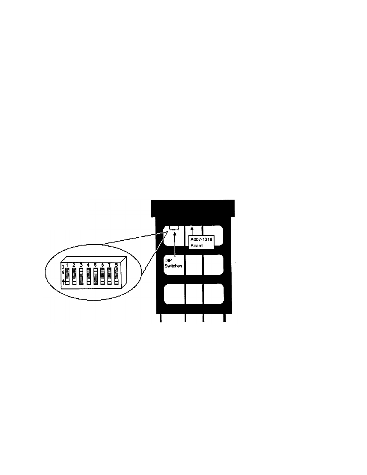
4. DIP Switch #6 determines a warm or cold start. Your
controller leaves the factory programmed for a warm
start.
Figure 2 DIP Switch Location and Orientation
Page 36 Despatch/Watlow 1500 Control Instruction Manual
Page 43

Warm/Cold Start (Cont.)
Table 10 DIP Switch Selection
DIP Switch
No.
1 Auxiliary (Event) Output #4 for both Ch-1
and Ch-2 are alarm outputs.
2 Alarms are latching (displayed until
cleared manually).
3 RTD Unit Only
The Ch-2 sensor is an RTD sensor.
Jumpers W151 and W153 on the signal
conditioner board (A007-1316) must be
installed.
T/C Unit Only
Not used. Set in the ON position.
4 Dual PID per channel. Single PID per channel.
5 Factory use only. Must be in the ON
position.
6 Cold start on power-up. (Memory
cleared, parameters set to default
values.)*
7 EC function after a cold start. EF function after a cold start.
8 Not used. Set in the OFF position.
ON OFF
FUNCTION
Auxiliary (Event) Output #4 for both Ch-1
and Ch-2 are event outputs.
Alarms are non-latching (displayed only
as long as the alarm condition exists).
The Ch-2 sensor is an RTD sensor.
Jumpers W151 and W153 on the signal
conditioner board (A007-1316) must be
installed.
Warm start on power-up. (Programmed
values are retained for all parameters.)*
Changing the Position of a Switch
Whenever you change the position of a DIP switch, follow
this procedure.
1. Remove power from the 1500. Turn the front panel to
loosen the controller from the case.
2. Grip the front panel bezel and pull it straight out from
the control case. The control chassis will come out of
the case as you pull the bezel.
3. Set the DIP switch to the position you want.
4. Return the control chassis to the case. Be sure you
have it oriented correctly. It will not fit in upside down,
but check just the same. Press firmly, but gently, to
seat the chassis.
Despatch/Watlow 1500 Control Instruction Manual Page 37
 Loading...