

Page 1
Secure Start Model 28622
v 0.2
Add On Remote Control Car Starter Installation Instructions
DesignTech International, Inc. • 7955 Cameron Brown Court • Springfield, Virginia 22153 USA • 703-866-2000 or 800-337-4468
Please Read Completely Before Beginning
Congratulations on your purchase of the Secure Start Add On Remote Car Starter. This remote car starter system allows you to
start the car by remote control from the comfort of your home or office in order to cool it down in the summer or heat it up in the
winter.
The Secure Start Remote Car Starter is for
automaticl transmission vehicles only. It is an extremely sophisticated system with
multiple built-in safety and security features.
The Secure Start Remote Car Starter:
• Will start your car by remote control, and run the heater, defroster, or air conditioner to warm up or cool down the car.
• Is designed to start the car if it is in park, and only if the hood is closed.
• Will attempt to start the car for up to six seconds, but no longer (to avoid damage to the starter motor). Should the car
not start, or if it stalls after starting, the remote starter will make two further attempts to start it.
• Will not let the car be driven without the key in the ignition.
• Shuts itself off automatically after 10 or 15 minutes (programmable) if you forget to come out to your car.
• Will shut off if the brake pedal is pushed, or the hood is opened - unless the key is in the ignition and in the “run” position.
• Allows you to remove the key while leaving the car running with the doors locked for up to 10 or 15 minutes utilizing the
QUICK STOP
• Is quality engineered, microprocessor controlled, and made in the USA to provide many years of reliable use.
• Comes with a 2 year warranty.
Tools required to install the remote starter unit:
Wire Cutters/Strippers Soldering Iron Pliers
TM
option. (See Separate User Tip Sheet)
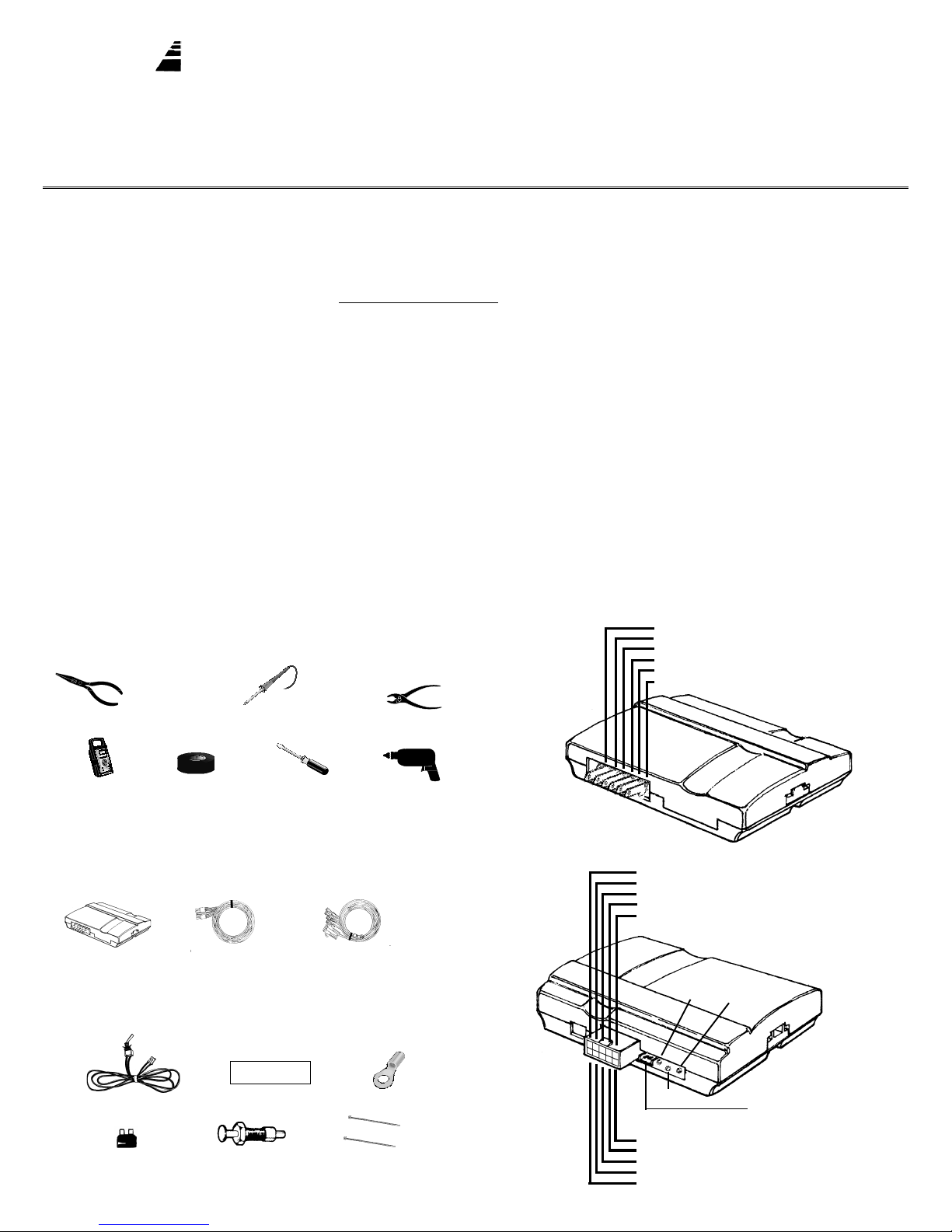
Power Harness
Wiring Diagram
Color Function Type Required
Pink Power (+12V) Input Yes
White Accesory / Lights Relay Output Yes
Yellow Starter Relay Output Yes
Blue Ignition 1 Relay Output Yes
Green Ignition 2 Relay Output Possible
Black Ground Input Yes
Testmeter Electrical tape Screwdriver Drill
We highly recommend that all connections be soldered for reliability.
Parts List:
Remote Start Module
Control Harness
(10 position)
Parts Kit in plastic baggy:
WARNING
This car is equipped with a remote control starting device.
Disable before working on car!
AVERTISSEMENT
Co véhicule est équipé d’un systéme de démarrage á distance. Mettez-le hors
fonctuin avant d’eflectuer toule opération d’entretian ou de répanation!
On/Off Control Switch Warning Label Ring Terminal
30 A Fuse
Hood Pin Switch Set 2 Cable Ties
6 Power &
Ignition wires
Control Harness
1
Color Function Type Required
Yellow/Green Alarm Control (+) 400 mA No
Green/White Sensor IN Relay No
Brown Accessory Pulse (-) 400 mA No
Brown/White Alarm Disable (-) 400 mA Possible
Gray/Black Sensor OUT Relay No
Left
White Button
LED
Color Function Type Required
Red/Black Diesel Input Input No
Red/White Remote - Input Yes
Green Tach Input No
Violet Hood - Input Yes
Orange Brake + Input Yes
Right
Red Button
Plug-in Control Switch
Page 2
On cars with airbags, you may notice bright yellow tubes or
harnesses underneath the steering column area. DO NOT
tamper with these wires in any way, to prevent personal
injury and/or damage to the air bag system.
Battery gases are explosive. Do not smoke while working near the car’s
battery.
Note: Some installers connect a battery charger to the
vehicle’s battery during installation. This is fine, but it must be
removed before running the vehicle under remote control.
5. Green (14 AWG) - Ignition 2
Connect the GREEN wire to the second IGN2 wire (if applicable) of your
vehicle. This wire will power the heater/air conditioner (in most cars). This
wire will measure +12V on the test meter in the “run” position only.
6. White Wire (14 AWG) - Accessory
Connect the WHITE wire to the accessory wire which is +12V in the “run”
and “accessory” position, but off (ground) in the “start” and “off” positions.
When working the wires through the car’s firewall, be sure to protect
them from sharp metal edges and from hot surfaces on the engine.
INSTALLATION INSTRUCTIONS
1. Before You Start
Take the time to read through the whole installation manual.
Always leave one window open to avoid locking your keys in your car.
IMPORTANT: After having read the entire manual, start the installation by
putting the yellow WARNING STICKER in the engine compartment. Choose
a surface that is clean and readily visible when the hood is open.
WARNING
This car is equipped with a remote control starting device.
Disable before working on car!
AVERTISSEMENT
Ce véhicule est équipé d’un systéme de démarrage a distance. Mettez-le
hors fonction avant d’eflectuer toute opération d’entretien ou de réparation!
POWER & IGNITION HARNESS
The remote starter module will be installed under the dash once all wiring
has been completed. Do not mount the module at this time! You will
need to check the diagnostic light (LED) as the installation progresses.
Locate (or drill) a hole in the firewall to run the VIOLET, and GREEN wires
of the Control Harness and the PINK wire of the Power harness through
into the engine compartment. The remaining short wires stay in the passenger area. Leave about a foot of the wire harness under the dash for
ease of working and visual access to the diagnostic light.
Note: Always connect the
of the other wires.)
Pink and Black wires before connecting any
2. Black Wire (16 AWG) - Ground
Connect the BLACK wire to a very good, clean chassis ground in the
driver’s kick panel area. Use the small red ring terminal if needed. The
metal bracing around or beneath the dash board is not adequate.
7. Yellow (14 AWG) - Starter
Connect the YELLOW wire to the starter wire. This wire will measure +12V
on the test meter in the “start” position only.
Note: Nissan vehicles have two starter wires. Connect both starter wires
to the YELLOW wire.
8. Plug-In On/Off Switch
Plug the ON/OFF control switch into the module just to the right of the
power wires. Use a 1/4” drill-bit for the mounting hole.
Note: Mount the control switch in the dash so that it is easily accessible
and so that the “ON” position is facing upward. Make sure there is
enough clearance behind the mounted switch for the wire connections.
Connection of this switch is mandatory.
Control Harness (All wires are the smaller 18 AWG size)
9. Red / Black Wire Diesel “wait to start” Control Harness
This wire is only used in diesel vehicle applications This wire should be
hooked up to the “wait to start” light’s switched wire behind the dash. If
option 9 is set, this wire wire will feed information to the remote starter as
to when to crank the vehicle over.
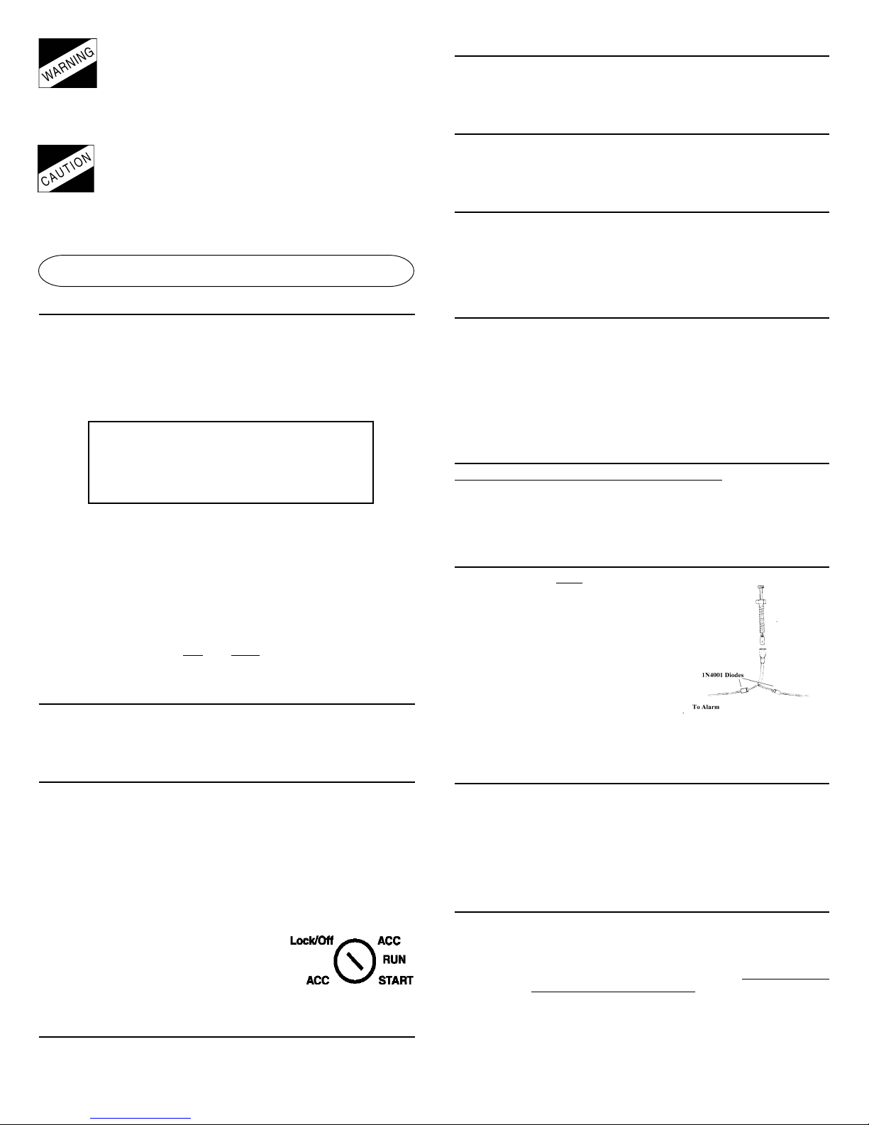
10. Violet Wire - Hood Pin Switch - Control Harness
The hood pin switch MUST be installed with
the remote starter. It prevents operation
of the remote starter when the hood is
open and is used to initialize the unit. Connect the VIOLET wire to the hood pin
switch using the red connector.
Note: If you already have a hood pin
switch which is being used by a car alarm
system, you may share the wiring -- but
be sure to diode isolate each wire going
to the hood pin switch with the bands of
diodes pointing towards the pin switch
as shown at right.
How to share a hood pin
switch with an alarm
To Remote Starter
3. Pink Wire (12 AWG) - Power (+12V)
Connect the ring terminal at the end of the short PINK wire to the +12 volt
terminal of the battery. Run the long pink wire through the firewall of
your vehicle. Join the remaining ends of the power wire together by
soldering them. Tape with electrical tape to leave no exposed wires.
Alternatively, you may wish to use a yellow butt terminal, but we recommend soldering. After all of your connections are complete, insert the
30 amp green fuse into the holder. As the power wire is connected the
LED will blink once.
Note: Failure to properly install the fuse holder and 30 amp fuse to the
pink wire voids all product warranties.
Ignition Key Diagram for Steps 4-7
The vehicle’s wires are found coming off of
the key switch. Remove the panel under the
steering column to access these wires.
4. Blue Wire (14 AWG) - Ignition 1
Connect the BLUE wire to the ignition 1 wire of your vehicle. This wire will
measure +12V on the test meter in the “run” and “start” position, and is
off (ground) in the “lock/off” and “accessory” position.
11. Orange Wire - Brake Shut-off - Control Harness
Connect the ORANGE wire to the brake wire which receives +12V when
the brake pedal is depressed. This wire must be connected. It arms a
critical safety feature which disables the remote starter when the brake
pedal is depressed.
Note: In some cars, the ignition must be in the “on” position to test the
power in the brake wire.
12. Initializing the Remote Starter
BEFORE THE CAR WILL START FOR THE FIRST TIME, YOU MUST INITIALIZE THE
REMOTE STARTER
A. Turn the control switch on.
B. The Remote Start Module requires the installer to
and then
come on if the unit is not initialized.
C. While depressing the brake (with the engine off and the hood open)
turn the ignition key to the “RUN” (not “start”) position.
D. Put the car in gear from the “PARK” position.
E. Put the car back in “PARK” and release the brake.
F. Turn the key off and remove key.
press and hold the brake pedal. Note: The dash lights will
2
open the hood
Page 3

Note: Confirm initialization by turning the ON/OFF control switch “OFF”
and then “ON”. The red LED on the Remote Start module will flash once
immediately as the switch is flipped from the “OFF” to the “ON” position.
If the unit is not initialized then the dash lights will come on (the Remote
Starter powers up the ignition wires) when the brake is depressed when
the hood is open when the control switch is on. REPEAT STEPS A THROUGH
F. See the purple colored Trouble Shooting Sheet if necessary.
13. Green Wire - Tach Input - Control Harness
The Remote Starter has two ways of monitoring the car during the starting process. Both ways will ensure a clean, accurate start.
both methods before deciding which one to use. Normally you should
try the “No TachTM” method first.
“No Tach
This starting method
TM
” Starting
does not require the connection of the GREEN tach
wire. This method will start the car by reading the car’s voltage before
attempting to start, and then looking for a voltage increase when the
alternator kicks in. This feature automatically takes into account voltage,
temperature, and the time since the vehicle was last run. The “No-Tach
starting is preset at the factory and you can skip step 13A if you would
like to use it. Note that if the vehicle is hard to start, set option #3 (step 22)
for “extended crank.”
Read about
TM”
starter will start on the second pulse. See “Setting Program Features.”
To reverse a positive trigger to a negative trigger, connect the relay as
follows:
1. Positive trigger output to terminal 86 on the relay.
2. (-) Ground to terminal 85 on the relay.
3. (-) Ground to terminal 87 on the relay.
4. Red/White wire from remote starter to terminal 30 on the relay.
See the “HOW TO USE A RELAY” section at the end of the instructions.
15. Providing an IGN 3 output or a Clutch Bypass
Many newer vehicles either have additional ignition circuits, alarm bypass units or the clutch needs to be triggered before the vehicle will
remotely start. By using additional relays, ignition circuits, alarm bypass
units and the clutch can be easily controlled. (The needed relays can be
easily purchased from DesignTech, Part # 20043 or Radio Shack, Cat #
275-226.)
Providing for a Clutch Bypass
To Ignition #1 in Vehicle To Key Side of Clutch Switch
Tachometer sensing
If the vehicle is generally hard starting (requiring a cranking time of more
than 1 second) you will get more accurate starting with the tachometer
sensing starting method. This method starts the car by reading the engine speed (tach) information from a wire under the hood. If you choose
tachometer sensing, connect the GREEN (18 awg) wire to the car’s tach
wire under the hood (normally the negative side of the coil or tach output of coil pack). After you have connected the GREEN wire, you need
to teach the Remote Starter the vehicle’s tach rate at idle. Proceed to
step 13A.
Note: You must have already initialized the module from Step 12.
13A. Tach Rate Learning
Note: Only use if the tachometer sensing method is chosen.
A. Connect the GREEN wire to the car’s tach wire under the hood.
B. Turn the On/Off control switch to the “OFF” position. Wait 5 seconds
for the first set of LED flashes to stop.
C. Push the White “option” button once and you will see the red LED
flash. Now push the middle button on the transmitter for a second
until you see the red LED flash again. You are now in TACH mode. (If
the LED flashed twice -- simply push the transmitter button again until
you get only one flash).
D. Wait 5 seconds for the red LED to flash 3 times.
E. Turn the On/Off control switch back to the “ON” position
F. Start the car and let it get to a normal idle. Do not press on the gas
pedal.
G. Push the red “code” button for a second.
H. Watch the red LED. It will turn on (solidly) after 3 or 4 seconds,
indicating that the idle rate has been learned.
I. Watch the LED stay on steady as the vehicle is running and goes off
as you rev the rpms above twice the idle rate. The LED must go out
when you rev it above twice the idle rate to confirm correct tach
learning.
J. Turn the key to the “Lock/Off” position.
K. Turn the On/Off control switch off and the LED will go out.
Note:
Once these steps are complete – you cannot use the LED to confirm
tach again. You can however repeat the above steps to learn tach over
again at any time.
14. Red/White – Remote Input Wire – Control Harness
The Red/White wire is used to trigger the remote starter to start the vehicle. A negative pulse will trigger the remote starter to start the vehicle.
A second negative pulse will shut the remote starter down.
Connect this wire to the AUX output of the alarm system or keyless entry
system. If installing this remote starter on a vehicle and using the factory
keyless system to trigger the remote starter connect this Red/White wire
to either the lock or unlock wire. (Check this lock or unlock wire again
using the factory transmitter to check that the output is correct.) The
Red/White must “see” a negative trigger. If the trigger outputs are positive, a relay must be used to reverse the polarity. There is a double pulse
feature, option #8. Trigger the unit twice in 3 seconds and the remote
Ground
87
30
85
86
Ignition #1 (Blue)
From Remote Starter
87
30
85
To Starter Side of
86
Clutch Switch
Ground
Providing an Ignition 3 Output
To Ignition #1 in Vehicle
Ground
87
30
85
86
Ignition #1 (Blue)
From Remote Starter
87
30
85
Ignition #3 Output
86
(-) Negative
Ground
Providing an Additional Ignition Circuit
To Ignition #1 in Vehicle
85
Ground
87
30
86
Ignition #1 (Blue)
From Remote Starter
85
To Additional
Ignition Circuits in
Vehicle
Fused 12 volt Constant
(Tap into Large Pink Wire
87
30
86
From Battery)
Ground
OPTIONAL STEPS
16. Yellow/Green - Alarm Control - Control Harness
The Yellow/Green wire is specifically designed to control the Ignition Input of the remote control alarm system, which is triggering the remote
starter. Connect this Yellow/Green wire directly to the Ignition Input of
the alarm. This Yellow/Green wire will provide a positive 12-volt output
anytime it “sees” a positive 12-volt on the vehicle’s ignition #1 wire. This
output follows the Ignition #1 status. The only exception is that when the
remote starter is powering the vehicle, this wire will not activate. The
3
Page 4

alarm remains operational during remote running because it is “blind” to
the fact that the vehicle is remotely running. This is a 300mA transistor
positive output.
17. Green/White - Sensor Loop IN - Control Harness
Gray/Black - Sensor Loop OUT - Control Harness
This Green/White wire is the input to a normally closed relay. When the
remote starter is running, this relay opens. If you have an external sensor,
like a shock sensor, pass the sense wire through this internal relay. When
the remote starter is running the vehicle, the relay is open and the alarm
does not “see” the input of the alarm sensor. When the vehicle is not
remotely running the alarm sensor works normally.
Cut the alarm sensor output wire in half. Connect one side of the cut
sensor wire to the Green/White wire and connect the other side of the
cut sensor wire to the Gray/Black wire.
18. Brown Wire - Accessory Pulse - Control Harness
The BROWN wire which is optional, is the Accessory Pulse output which
gives out a transistor ground output just as the Accessory wire comes on.
This is important in unusual vehicles to control the defroster or to control
the GM R.A.P. system.
which MUST drive a relay (not included).
Again, this is a 400 mA transistor ground output
19. Brown/White - Alarm Disable - Control Harness
The BROWN/WHITE wire which is optional is Alarm Disable, which will give
out a quick negative pulse just before starting the vehicle. This wire can be
used to turn off the factory alarm system in vehicles which have them. In
most vehicles this disarm wire is located in the driver’s kick panel.
22. Setting Program Features:
The remote starter unit has several special features available. You will
not need to use these special features in most situations. The factory
settings will operate most vehicles. You must turn the On/Off control switch
to the “OFF” position to program any features. Note that when turning off
this control switch, the red LED will flash a few times, giving the diagnostic
code described in Section 21. Wait a few seconds for it to finish before
programming your new Options.
Feature # Factory Setting (2 flashes) Option (1 flash)
1 “No-Tach” Tach Mode
2 10 min. run time 15 min. run time
3 Normal Crank Extended Crank
4 Nor mal Crank Super Crank
5 Normal Voltage Metering Ignore Voltage Metering
6 Gasoline Vehicles Diesel Vehicles
7 “Enable” Feature No “Enable”
8 Nor mal Trigger Double Pulse Trigger
Option 1 “No-Tach” Tach Mode
Sets the starting method. The factory setting uses “No-Tach” starting. If
you wish to use the tach to start, follow the instructions in step #13.
Option 2 10 min. run time 15 min. run time
Gives you a choice of run times, either 10 or 15 minutes.
Option 3 Normal Crank Extended Crank
Will add 50% more cranking time to the “No-Tach” starting method.
Option 4 Normal Crank Super Crank
Adds 100% more cranking time to the “No-Tach” starting method. This
may be necessary on many diesels and hard to start vehicles.
REQUIRED FINAL STEPS
You must have hooked up all required wires and completed Initialization
(Step 12) to proceed forward.
20. Trying the Unit Out
WARNING: Be prepared to apply the brake during this testing. Close the
hood, fully apply the emergency brake. Turn the On/Off switch On, the
red LED will flash once.
A. Once all the wiring is checked and is correct put the vehicle in “park”,
the press the button on the transmitter of the host alarm or keyless
entry system, which controls the remote starter. Simply grounding
the Red/White wire will also trigger the remote starter to start.
B. The vehicle should start and continue to run for 10 minutes. Please
make sure that the engine shuts down if the vehicle is taken out of
“park”, the hood is opened of the brake is pressed.
21. Trouble Shooting with the Self Diagnostics
The remote starter contains a built in diagnostic routine that will indicate
why the unit started or why the unit turned off the car the last time that
the unit was used.
To activate the diagnostic mode for
Off control switch to the “OFF” position. In a few seconds, the red LED on
the module will flash 1 to 12 times to identify the problem. See the chart
below for an explanation of the flashes:
1 flash 10/15 minute time out. Unit should be fine.
2 flashes Unit turned off because Brake or Hood was activated.
3 flashes No Tach sensing or Stalled. Review Step 13.
4 flashes Received another remote input door pin switch problem.
6 flashes Low battery voltage, or may be missing an ignition wire which
powers up the alternator
7 flashes Alarm Input triggered
8 flashes Over current - One of the 400 mA (-) transistor outputs of the
control harness is driving too much current. Make sure to use a
relay where necessary.
12 flashesThe Control Switch was turned off.
If you have any questions on the trouble shooting, see Step 10 of the
purple Trouble Shooting Guide.
why it turned off, simply turn the On/
Option 5 Normal Voltage Metering Ignore Volate Metering
Is used in the “No-Tach” starting method for some diesel vehicles or
vehicles that have poor electrical charging systems.
Option 6 Gasoline Vehicles Diesel Vehicles
This option is selected when installing into a diesel vehicle.
Option 7 “Enable” Feature No “Enable”
Cancels the Enable mode safety feature. The Enable mode requires
that the driver toggle the ON/OFF control switch “OFF” then “ON” in
order to “Enable” the vehicle to remotely start. This feature guards against
the accidental starting of the vehicle by the remote starter.
Option 8 Normal Trigger Double Pulse Trigger
Normal trigger will start and stop the remote starter with a single quick
ground pulse to the Remote Input wire. Double Pulse Trigger mode will
not activate the remote starter until it has seen two pulses within a 3second period of time. If the Remote Input wire is connected to the
door lock wire of the keyless entry module, you can lock the doors with
just one push of the transmitter’s lock button. If the transmitter’s lock
button is pushed again within 3 seconds, you will lock the doors AND
start the vehicle.
If you want the factory setting, DO NOTHING and skip this section. If you
want to change one of the features, TURN THE ON/OFF CONTROL SWITCH
TO THE “OFF” POSITION.
tinue with the following procedures:
A. For options 1-8: Push the white button to the left of the red LED. Each
time you push the button the red LED will flash 1 to 8 times signifying at
which feature you are (press it once, the LED flashes once. Press it
again and it will flash two times. Press it again and it will flash three
times, etc., to show what feature you are at).
B. When you are at the feature level you desire, push the Red button for
a second and the red LED will flash
Option setting. You can push the Red Option button again and it will
flash
Twice to signify you are at the Factory setting. Push the Red
Option button again and you will go back to the Option setting.
C. You can choose to change another feature by starting over again at
Step A. or, in six seconds, the
programming mode (Three LED flashes).
D. When finished -- switch the Control Switch back ON. The LED will flash
once.
Wait for the red LED to stop flashing, then con-
once to signify you are at the
remote starter
automatically exits the
4
Page 5

23. Factory Anti-Theft Systems
Many vehicles come with an anti-theft system that must be temporally
bypassed for the vehicle to be remotely started. Some systems use a
resistor in the key. Others use a transponder- a small device in the key
that communicates a high security code to the vehicle before the vehicle will successfully start.
Check the following list of vehicles below. If your vehicle is listed, your
vehicle has an Anti-Theft System that the remote starter MUST temporally
bypass in order to start the vehicle.
HOW TO USE A RELAY
Many of the optional steps require a relay to be hooked up. The most
common relay used for this type application is the Bosch type relay (Radio Shack Cat.# 275-226). Use the diagram below for a typical hookup.
If you have another relay then you need to know that pins 85 and 86 in
this diagram relate to the coils of the relay. Pin 30 is the ‘common’, and
pin 87 is the ‘normally open’ contact. If your relay has a pin 87A in the
middle it is the normally closed contact and is not used.
A Universal Alarm Bypass Module, model #20402, that will temporally
bypass the factory anti-theft systems when using the remote starter. Check
with your local retailer/installer to purchase this Universal Alarm Bypass
Module, model #20402.
List of vehicles and the types of security systems:
Acura 3.2TL 98+ Transponder
Acura CL 97+ Transponder
Acura RL 98+ Transponder
Acura Integra 2000 Transponder
Acura NSX Transponder
Audi A4, A6, A8 98+ Transponder
BMW (all 97+) Transponder
Buick Century 97+ VATS
Buick LeSabre 90 – 96, 2000 VATS
Buick Park Ave 91 - 96 VATS
Buick Park Ave 97+ Transponder
Buick Regal 93 -96 VATS
Buick Riviera 93 -96 VATS
Buick Roadmaster 93 - 96 VATS
Buick Skylark 96 - 98 Passlock
Cadillac Allante VATS
Cadillac Brougham VATS
Cadillac Catera Transponder
Cadillac DeVille 92 - 96 VATS
Cadillac DeVille 99+ Transponder
Cadillac Eldorado 89 - 98 VATS
Cadillac Eldorado 99+ Passkey 3
Cadillac Escalade 99+ Passlock 2
Cadillac Fleetwood 90 - 96 VATS
Cadillac Seville 90 - 98 VATS
Cadillac Seville 99+ Passkey 3
Cadillac SLS/STS 97+ Passkey 3
Chevy Astro Van 98+ Passlock 2
Chevy Blazer 98+ Passlock 2
Chevy Camaro 86+ VATS
Chevy Cavalier 96-99 Passlock
Chevy Cavalier 2000 Passlock 2
Chevy Corvette 88+ VATS
Chevy Express 97+ Passlock 2
Chevy Impala 2000 Passkey 3
Chevy Lumina 96+ VATS
Chevy Malibu 97+ Passlock 2
Chevy Monte Carlo 96 - 99 VATS
Chevy Monte Carlo 2000 Passlock 2
Chevy Pickup Full-size 98+ Passlock 2
Chevy S-10 98+ Passlock 2
Chevy Savanah Passlock 2
Chevy Suburban 98+ Passlock 2
Chevy Tahoe 98+ Passlock 2
Chevy Van 98+ Passlock 2
Chevy Venture 99+ Passkey 3
Chrysler Concorde 98+ Transponder
Chrysler LHS 99+ Transponder
Chrysler Sebring Conv 98+ Transponder
Dodge 300 M 99+ Transponder
Dodge Intrepid 98+ Transponder
Dodge Neon 2000 Transponder
Ford Contour 97 + P.A.T.S.
Ford Crown Vict. 98+ (opt’l) Transponder
Ford Excursion 2000 P.A.T.S.
Ford Expedition 97+ P.A.T.S.
Ford Explorer 98+ P.A.T.S.
Ford Focus 2000 Scurlock
Ford Mustang 98+ P.A.T.S.
Ford Pickup (F150/F250) 98+ P.A.T.S.
Ford Ranger 99+ (optional) P.A.T.S.
Ford Taurus 96 + P.A.T.S.
Ford Windstar 2000 P.A.T.S.
GMC Denali 99+ Passlock 2
GMC Envoy 99+ Passlock 2
GMC S-15 Jimmy 98+ Passlock 2
GMC Safari 98+ Passlock 2
GMC Sierra Pickup 98+ Passlock 2
GMC Sonoma 98+ Passlock 2
GMC Suburban 98+ Passlock 2
GMC Yukon 98+ Passlock 2
GMC Yukon XL 2000 Passlock 2
Honda Accord 98+ Transponder
Honda Odyssey 98+ Transponder
Honda Prelude 98+ Transponder
Honda S2000 Transponder
Infinity I30 98+ Transponder
Infinity Q45 98+ Transponder
Infinity QX4 Transponder
Jaguar (all 98+) Transponder
Jeep Grand Cherokee 99+ Transponder
Jeep TJ (Wrangler) 99+ Transponder
Lexus (all 97+) Transponder
Lincoln Continental 97+ P.A.T.S.
Lincoln LS 2000 P.A.T.S.
Lincoln Mark V3 97+ P.A.T.S.
Lincoln Navigator 97+ P.A.T.S.
Lincoln Town Car 97+ P.A.T.S.
Mercedes (all 97+) Transponder
Mercury Cougar 99+ P.A.T.S.
Mercury Mountaineer 98+ P.A.T.S.
Mercury Mystique 97+ P.A.T.S.
Mercury Sable 96+ P.A.T.S.
Nissan Maxima 98+ Transponder
Oldsmobile Achieva 95+ Passlock
Oldsmobile Alero 99+ Passlock 2
Oldsmobile Aurora VATS
Oldsmobile Bravada 98 Passlock 2
Oldsmobile Cutlass 97+ Passlock 2
Oldsmobile Eighty-Eight VATS
Oldsmobile Intrigue 98+ Passlock 2
Oldsmobile Ninety-Eight VATS
Oldsmobile Silhouette 99+ Passkey 3
Pontiac Bonneville 89+ VATS
Pontiac Firebird 88+ VATS
Pontiac Grand Am 96 - 98 Passlock
Pontiac Grand Am 99+ Passlock 2
Pontiac Grand Prix 92 – 96 VATS
Pontiac Montana 99 Passkey 3
Pontiac Sunfire 96-99 Passlock
Pontiac Sunfire 2000 Passlock 2
Porsche (most 97+) Transponder
Saab (all 97+) Transponder
Saturn 97+ Factory
Saturn 2000 Passkey 3
Toyota Avalon 98+ Transponder
Toyota Camry 98+ Transponder
Toyota Land Cruiser 98+ Transponder
Toyota Solara 99+ Transponder
Toyota Supra 98+ Transponder
Volkswagon Beetle 98+ Transponder
Volkswagon Golf 98+ Transponder
Volkswagon Passat 98+ Transponder
Volvo (all 98+) Transponder
To Supply Ground (–) output
To Ground
From
Remote
Starter
87
30
85
To Vehicle's Accessory
86
+12 V
From
Remote
Starter
12 Volt Constant
12 Volt Constant
87
30
85
To Vehicle's Accessory
86
+12 V
Important Note:
Make sure that all drivers who will be operating the remote starter are
fully aware of the safety precautions installed and their limitations. Stress
the importance of switching the On/Off control switch to the “OFF” position (down) every time the car is serviced. Give the user a copy of the
tan page - USER TIPS AND NOTES so that they can familiarize themselves
with the product.
USER INFORMATION: The tan USER TIPS AND NOTES sheet gives you further
detail regarding daily use of this product. Any modifications not expressly
approved will void the user’s authority to operate the equipment.
7955 Cameron Brown Court; Springfield, Virginia 22153 USA
Tel: (703)866-2000 or (800)337-4468
www.designtech-intl.com
PLEASE HAVE MODEL NUMBER (28622) AND DIAGNOSTIC CODES
OF (STEP 21) READY BEFORE CALLING TECH SUPPORT
5
 Loading...