

Page 1
v 1.0
AutoCommand
®
Remote Control Car Starter
Models 28636 - 28638
With Full Keyless Entry
& Security Alarm Features
Installation Manual
For use on automatic vehicles only.
For gasoline or diesel vehicles.
Delux Long-Range ‘Super-het’ model
7955 Cameron Brown Court
Springfield, Virginia USA
Tel: (703) 866-2000; Fax: (703) 866-2001
www.designtech-intl.com
Page 2

Congratulations on your purchase of the AutoCommand® Remote Car Starter. This
Remote Car Starter system allows you to start the car by remote control from the
comfort of your home or office in order to cool it down in the summer or heat it up in
the winter.
This Remote Car Starter system is for
extremely sophisticated system with multiple built-in safety and security features.
automatic transmission cars only. It is an
!! WARNING !!
Do not hook this remote car starter into a manual transmission vehicle.
Doing so could cause serious property damage, personal injury, and will
void all warranties. DesignTech International, Inc. will not be held responsible for any resulting damages or injuries if this remote car starter
unit is installed in a stick shift vehicle.
The DesignTech Remote Car Starter:
• Will start your car by remote control, and run the heater, defroster, or air condi-
tioner to warm up or cool down the car.
• Is designed to start the car if it is in park, and only if the hood is closed.
• Will attempt to start the car for up to six seconds, but no longer (to avoid damage
to the starter motor). Should the car not start, or if it stalls after starting, the
remote car starter will make two further attempts to start it.
• Keeps the headlights on to let you know the car is running, and has the ability to
use your transmitter to light your way when walking to the car at night.
• Will not let the car be driven without the key in the ignition.
• Shuts itself off automatically after 10 or 15 minutes (you choose the run time -
consult your installer) if you are delayed coming to your car (20/30 min for deisels).
• Will shut off if the brake pedal is pushed, the hood is opened, or the transmission
is shifted out of park - unless the key is in the ignition and in the “run” position.
• The QUICK STOP
while leaving the car running with the doors locked for either 10 or 15 minutes.
• The COLD START OPTION
should the temperature drop below either 0’F (-18’C) or if the battery voltage
drops below 11 volts.
• Lock and Unlock the doors and open the trunk as well as control security alarm
features with the transmitter.
• Comes with a built-in starter kill relay to prevent vehicle theft.
•· Comes with a plug-in Flashing status LED.
• DAILY START
the same time 24 hours later. Great if you go to or leave from work at the same
time each day.
• Using the built-in DAYTIME RUNNING LIGHTS feature you can automatically
turn on your lights 10 seconds after the key is turned to the ignition position or the
brake is depressed.
• Is quality engineered, microprocessor controlled, and made in the USA to provide
many years of reliable use.
tm
option using the transmitter will allow you to remove the key
tm
using the transmitter starts the car automatically
tm
feature allows you to have the vehicle automatically start up at
Tools required to install the AutoCommand® unit:
◊ Test meter
◊ Wire cutters/strippers
◊ Pliers
◊ Screwdrivers
◊ Drill and 1/4” drill bit to mount the switch & 5/16” bit for the LED.
◊ Soldering iron and solder
We highly recommend that
all connections be soldered for a long lasting
connection.
Parts list
1 Remote Car Starter module
1 Miniature 3 button transmitter
1 Control harness (10 position)
1 Accessory harness (8 position)
6 Power & Ignition wires and one short pink battery wire
with fuse holder.
1 Model 20038 includes all of the above parts plus
• shock sensor
• siren
• an additional 3 button transmitter
1 Parts Baggy
Parts kit in plastic baggy:
• Extra YELLOW Starter Kill wire
• External LED with plug-in connector
• 2 Butt connectors for starter kill.
• Control switch with plug-in connector
• 30 Amp Green fuse
• Small ring terminal for ground wire
• 2 Cable ties
• 2 Antenna clips with for mounting antenna
• Alcohol pad for cleaning windshield for antenna clips
• Pin switch, washer, nut and tab connector (for hood)
• Yellow “Warning” label
• “Protected by DesignTech” window decal
28636 - 28638 Page 3Page 2 28636 - 28638
Page 3
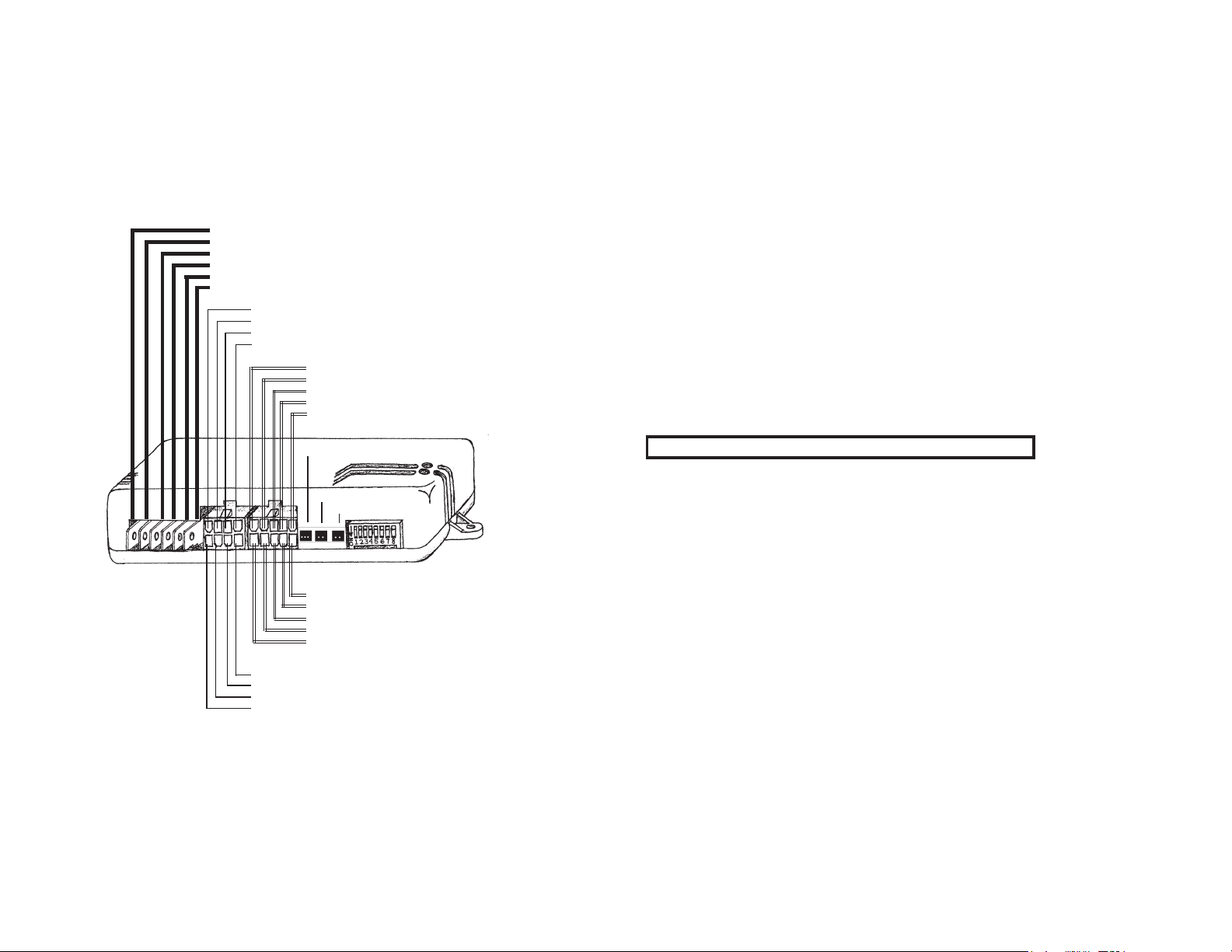
AutoCommand Wire Harness
Color Function Type Required
Thick Pink Power(+12V) Yes
Thick White Accessory Relay output Yes
Thick Yellow Starter Relay output Yes
Thick Blue Ignition 1 Relay output Yes
Thick Green Ignition 2 Relay output Maybe - Consult Wiring Guide
Black Ground Yes
Color Function Type Required
White/Red Lock Common Relay output No
Yellow/Green Unlock Normally Closed Relay output No
White/Green Lock Normally Closed Relay output No
Yellow/Red Unlock Common Relay output No
Color Function Type Required
Yellow Lights Relay ou tput No
Blue Horn Relay outp ut No
Brown Acc. Pulse/Dome Light Output (-) No
Brown/White Alarm Disable Output (-) Maybe
White/Black Ignition 3 Output (-) No
!! WARNING !!
If you are working on a newer car, you may notice bright yellow tubes or
harnesses underneath the steering column area. These are the “SRS” or AIR
BAG wires. DO NOT tamper with these wires in any way, since this could
result in personal injury and/or damage to the air bag system.
Battery gases are explosive. Do not smoke while working near the car’s
battery.
!! CAUTION !!
When fishing wires through the car’s firewall, be sure to protect them from
sharp metal edges and from hot surfaces on the engine.
NOTE: Some installers hook a battery charger up to the vehicle’s battery
during the installation. This is fine, but it must be removed before running
the vehicle under remote car starter control.
INSTALLATION INSTRUCTIONS
Optional Shock Sensor Jack
Plug In Switch
Plug In LED
Color Function Type Required
Red/Black Diesel “wait to start” Input (+/-) No
Red/White Remote Input Input (-) No
Green Tach Input No
Violet Hood Input (-) Yes
Orange Brake Input (+) Yes
Color Function Type Required
Gray Alarm Trigger Input (-) No
White Ground out while armed Output (-) No
Green/White Trunk / Carburetor Output (-) No
Gray/Black Door Pin Switch Input (-) No
For vehicle specific wiring information -- consult the Blue Sheet
for general information and consult our Web sit for more specific
information. www.designtech-intl.com.
1 BEFORE YOU START
Take this time to read through the entire installation manual. Reading
the manual now will save significant time in the long run. ALL STEPS
ARE CRITICAL.
The installation information section or our web site www.designtechintl.com is available 24 hours/day to provide you with up to date vehicle
wiring information for your particular vehicle if needed.
Wire Harnesses: Always check your wire harness before installing to
make sure that it matches the list/drawing on page 4 of the manual. You
can use the BLUE WIRE COLOR SHEET to help determine the col-
ors of the wires in your vehicle -- but be sure to always check these using
a volt-meter since vehicle wire colors can change from year to year in
vehicles.
When you have read the entire manual, and paid close attention to every
step, start the installation by putting the Yellow WARNING STICKER
under the hood. Pick a surface that is readily visible with the hood open
and will not be easily covered with grime. Make sure that the surface is
clean and grime free before applying the sticker.
28636 - 28638 Page 5Page 4 28636 - 28638
Page 4
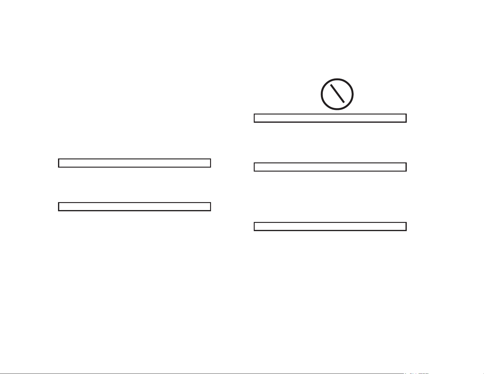
All dipswitches should be OFF (up position) during the installation.
POWER & IGNITION WIRES
The AutoCommand® module (large black box) will be installed under the dash,
once all wiring has been completed. Do not mount the module at this time
because you will need to check the diagnostic lights as the installation
progresses. Locate (or drill a hole) in the firewall to run all of the long wires (12
AWG PINK, 18 AWG YELLOW, VIOLET, GREEN, and BLUE) through the firewall
to the engine compartment. The remaining short wires stay in the passenger
area. Leave about a foot of length at the harness end under the dash for ease of
working and visual access to the diagnostic lights.
(Note: Always connect up the
any of the other wires.)
Black and Pink wires before connecting up
Ignition Key Diagram for Steps 4-7
Lock/Off ACC
RUN
ACC START
4 Thick Blue Wire Ignition 1
Attach the Thick BLUE 14 gauge wire (Ignition 1) to the ignition 1 wire
coming off the key switch behind the steering column. This is a wire which
shows positive (+12v) on the test meter in the run and start position, but is off
in the lock/off and accessory position.
2 Black Wire Ground
Optimum ground connection is critical for proper operation of this unit, as well
as transmitter range. Connect this BLACK wire to a very good clean chassis
ground in the driver’s side kick panel area. Use the small red ring terminal if
needed. The metal bracing around or beneath the dash board is not adequate.
3 Long Pink & Short Pink Wire Power (+12V)
The LONG PINK wire goes through the fire wall and connects to the SHORTER
PINK wire with fuse holder. We recommend getting power directly at the
battery +12V terminal. Connect the ring terminal on the SHORT PINK wire to
the +12 volt terminal of the battery. Strip back some insulation and then solder
the two ends of the PINK wires together, or use the Yellow Butt connector to
connect these. Either way, you must have a very good connection.
30 Amp green fuse.
As soon as the Pink (Power) wire is connected the GREEN LED will come on and
go out. (If the unit is already initialized, the GREEN LED will come on for several
seconds while the RED LED flashes 4 times.)
NOTE: WE STRONGLY RECOMMEND GETTING POWER AT THE
BATTERY. ALSO, FAILURE TO INSTALL THE FUSE HOLDER AND
30 AMP FUSE TO THE PINK WIRE VOIDS ALL PRODUCT WARRANTIES, BOTH WRITTEN AND IMPLIED!
Install the
5 Thick Green Wire Ignition 2
Most cars (especially newer cars) have a second ignition wire that is necessary. Use the Thick GREEN 14 gauge (Ignition 2) wire for this connection.
This is a wire that shows positive (+12V) on the test meter in the run position.
It may be best to leave this wire until the end to determine whether the vehicle
needs this wire to operate some of the accessories. Note -- setting dip-switch
option 10 (described in Step 29) will cause this wire to be off during crank.
6 Thick White Wire Accessory
Attach the Thick WHITE 14 gauge wire to the accessory wire coming off of
the key switch behind the steering column area. This is a wire which shows
positive (+12v) on the test meter in the run and accessory position, but is off
in the start and off position.
28636 - 28638 Page 7Page 6 28636 - 28638
Page 5
7 Thick Yellow Wire Starter
Attach the YELLOW 14 gauge wire to the starter wire coming off of the key
switch in the steering column area. This wire is hot (+12V with a meter) in the
start position only. It is off in all other positions.
CONTROL HARNESS
8 On/Off Plug-in Control Switch
This switch must be installed for the remote starter to operate. Mount the
switch then plug this switch harness into the AutoCommand module at the 2
pin white connector. (See diagram on page 4).
Mount the control switch so that the “On” position is facing upward.
Connection of this switch is mandatory.
9 Red/Black Wire Diesel “wait to start” / PAGER Control Harn.
This wire is used in diesel vehicle applications - and is optional. This wire
can be hooked up to the “wait to start” light’s switched wire behind the dash,
or directly to the glow plug wire. The sense wire must change state when the
Wait to Start light turns on. If dip switch option 9 (described in Step 29) is
set, this wire will feed information to the remote starter as to when to begin
starting the vehicle.
This wire can also be used with DesignTech’s Nationwide Pager (model
28010). In Data-Link mode, one can control all features of the remote starter
via any telephone. If the pager is used in Data-Link mode, this wire cannot be
used for Diesel applications. Follow the separate Pager directions for installation.
10 Violet Wire Hood Pin Switch Control Harness
The hood pin switch must be installed for the unit to initialize and work
properly. It prevents operation of the remote starter when the hood is open.
Attach the VIOLET 18 gauge wire to the supplied pin switch using the hardware provided. Be sure to have a good ground connection.
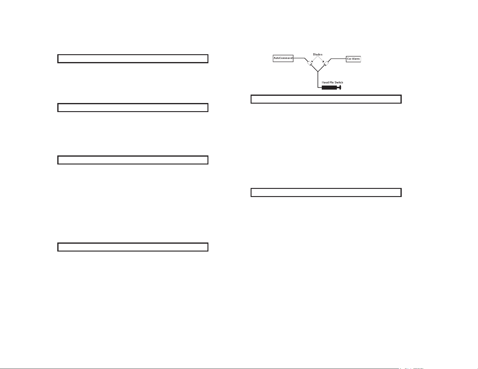
If you already have a hood pin switch which is being used by a car alarm
system, you may share the wiring -- but be sure to diode isolate each wire
going to the hood pin switch. See following diagram:
11 Orange Wire Brake Shut-off Control Harness
The ORANGE 18 gauge wire will disable the remote starter when the brake
pedal is pressed down. This is an added anti-theft safety feature. This connection is usually made under or behind the brake pedal linkage at the switch.
Connect the ORANGE wire to the wire that receives +12V only when the
brake pedal is pressed down. Any +12V input on this wire will shut off the
AutoCommand®. In some cars, the ignition must be on to see power at the
brake wire. This wire must be hooked up. This is a critical safety feature.
This connection is also required for several options discussed later.
NOTE: With the Valet switch connected and in the ON position, pushing on
the brake pedal with the hood open (hood pin switch at ground) at this time
will cause the ignition wires to power up unless the unit has been initialized
as described in the next step.
12 Initializing the Remote Starter
BEFORE THE CAR WILL START FOR THE FIRST TIME, YOU MUST
INITIALIZE THE REMOTE STARTER WITH THE HOOD OPEN.
A. The Remote Starter requires the installer to open the hood, and press and
hold the brake pedal. If the unit is not initialized at this time -- this
action will cause the ignition outputs to come on (i.e. the dash lights come
on) informing you that the unit is
B. While depressing the brake (with the engine off and the hood open), turn the
key to the “RUN” (not “start”) position.
C. Put the car in GEAR from the PARK position.
D Put the car back in PARK and release the brake. The GREEN LED should
have flashed twice when you did this -- then 2 seconds later, the Green LED
will stay on while the Red LED will give 4 quick flashes. (The remote starter
looks at the vehicle’s neutral safety switch and checks for an automatic trans-
mission during this step.)
E. Turn off the key and remove key from ignition.
You can confirm that the unit has been ‘initialized’ — simply turn the ON/OFF
switch OFF and then ON. The GREEN LED (or dashmount LED) on the AutoCommand module will flash once immediately as the switch is flipped from the off
not initialized.
28636 - 28638 Page 9Page 8 28636 - 28638
Page 6

to the on position confirming that the unit has been ‘initialized’. The ignition
wires will also
IF THE UNIT DOES NOT INITIALIZE AT THIS TIME, see the purple Trouble
Shooting Sheet.
13 Green Wire Tach Input Control Harness
The Remote Starter has two ways of monitoring the car during the starting process.
Either way will ensure a clean, accurate start. Read about both methods before
deciding which one to use.
“No Tach
This starting method
method will start the car by reading the car’s voltage before attempting to start, and
then looking for a voltage increase when the alternator kicks in. This feature automatically takes into account voltage, temperature and the time since the vehicle
was last run.
The “No-Tach
you can skip the rest of this step and proceed to Step 14 should you choose it. Note
that some hard to start vehicles may require option 3 to be set for “extended crank”.
Tachometer sensing
If the vehicle is generally hard starting (requiring a cranking time of more than 2
seconds) you will get more accurate starting with the tachometer sensing starting
method. If you are installing the remote starter on a carbureted vehicle, you must
use the tachometer sensing. This method starts the car by reading the engine speed
(tach) information from a wire under the hood. If you choose tachometer sensing,
connect the GREEN wire to the car’s tach wire under the hood. After you have
connected the GREEN wire, you need to teach the remote starter the vehicle’s tach
rate. Set the Tach rate as follows:
not come on when the brake is depressed if the unit is initialized.
TM
” Starting
does not require hooking up the GREEN tach wire. This
TM
” starting method is preset at the factory (dip switch 3 OFF), and
TACH RATE LEARNING
A. Connect the GREEN wire to the car’s tach wire under the hood.
B. Turn the Control Switch OFF. Wait 5 seconds for the flashing of the
GREEN LED to stop.
remote starter module, make sure dip switch 3 is in the ON (down)
C. On the
position
D. Start the car and let it get to a normal idle.
E. Keep your foot clear of the gas pedal to prevent varying engine speed
F. Flip dip switch #2 to the ON (down) position.
G. Watch the RED LED. It will come on after 3 or 4 seconds, indicating the
idle rate has been learned.
H. RETURN DIP SWITCH #2 TO THE OFF (UP) POSITION (LEAVE DIP
SWITCH #3 DOWN -- ON)
OPTIONAL STEPS
14 Yellow Wire Headlights/Parking Lights Control Harness
The optional YELLOW 18 gauge wire activates the low beam headlights or
the parking lights with a built-in 15 amp 12 volt relay. This feature provides
visual indication that the car has started. After the
fully started the car, the lights will come on and stay on until the system shuts
off, or until the key is inserted into the ignition and the car is driven. Hook
the YELLOW wire to the low beam headlights or the parking lights if you
desire this feature. (Note: There is a 15 Amp fuse in the case for the headlight circuit. This is the one furthest from the power wires. Check this fuse if
you have no output).
15 Blue Wire Horn/Siren (or Trunk) Control Harness
This wire puts out a pulse once each time the remote starter starts the car. It
also is used to confirm Lock and Unlock and in the various CarFinder® and
Panic/Alarm modes.
The AutoCommands have a +12 volt relay output which can directly drive a
horn or siren.
If connecting up to a
horn. The ground side of the horn is probably arleady going to ground.
If connecting up to a
siren and the black ground wire of the siren goes to ground. Note: See Step
29 Option 11 for changing from the factory setting of ‘horn’ mode to the
‘siren ‘ mode.
This output can also be used to supply a +12 volt relay output to power an
electric trunk by setting option 22 (Described in Step 29). If set, the BLUE
wire now acts like a 12 volt positive trunk output and the GREEN/WHITE
wire refered to in Option 22 now acts as a negative (-) horn/siren output. This
GREEN/WHITE wire is a negative transistor output which can be used to
directly drive the negative going horn wire at the steering column.
horn, this BLUE wire goes to the positive wire for the
siren, this BLUE wire goes to the positive wire for the
remote starter has success-
28636 - 28638 Page 11Page 10 28636 - 28638
Page 7

16 Brown Wire Accessory Pulse/Dome LampControl Harness
The BROWN wire is the acessory pulse which gives you a quick pulse just
before the car starts or stops. This is a 500 mA transistor ground output which
MUST drive a relay (not included) which in turn will supply either ground or
positive signal. This is important in some vehicles to control the defroster or to
control the GM R.A.P. system, or to re-lock power door locks if the vehicle
automatically unlocks them whenever the vehicle stops running.
You can also use the dip-switch option 20 (described in Step 29) to change this
output to turn on the dome lamp when the doors are unlocked. This is a 500
mA transistor ground output which
supply either ground or positive signal to the door pin switch wire. Most GM
vehicles, most Chrysler vehicles and most Japanese vehicles require a ground.
Most Ford cars and trucks will require a positive +12 v output.
MUST drive a relay which in turn will
17 Brown/White Alarm Disable Control Harness
The BROWN/WHITE wire will put out a quick negative pulse just before
unlocking or starting the vehicle. This wire is used to turn off the factory
alarm. Connect this Brown/White wire directly to the factory alarm disarm
wire. This wire is usually located in the driver's kick panel. Refer to the
"factory disarm" column of the blue vehicle wiring guide to determine the
color code of your particular vehicle.
18 White/Black Wire IGN 3 / VATS Control Harness
The WHITE/BLACK wire is a 500 mA transistor ground output that acts just
like the IGN1 or IGN2 relay outputs. It is active during run and crank. This
wire MUST be set up to power a relay. With a relay, it can be used to power
the third ignition wire at the ignition key.
The WHITE/BLACK wire comes on before anything else, and turns off 2.5
seconds after the last wires turn off. Consequently one of the most common
uses for this wire is for a VATS disable wire. See SPECIAL CASES for using
this with the VATS system.
ACCESSORY HARNESS
20 Gray & Gray/Black Alarm Inputs Accessory Harness
Important Note: If you want to use the keyless entry features only - with
no alarm functions - connect the GRAY wire to ground or set Option 24
(described in Step 29) for No Alarm mode .
The GRAY alarm input wire will accept any negative alarm input, including:
shock sensors, perimeter sensors, etc. When connecting a shock sensor or
microwave sensor, always use the GRAY wire. AutoCommand ignores this
input during the remote starting and when the AutoCommand is running the
vehicle, preventing false triggering.
Model 20038: If you are using the
simply plug it into the 3 pin connector jack shown on page 4. The GRAY
wire is in parrallel with the Shock Sensor’s output wire -- thus care needs
to be taken (i.e. diode isolate this wire) if you want to use the GRAY wire
for any other sensor as well.
If you are using a sensor or input that switches to (+) when triggered, you will
need to reverse the polarity with a relay before connecting to the GRAY wire.
The GRAY/BLACK wire is normally for the door pin switch and will be
temporarily disabled for the first 45 seconds of starting (this prevents vehicles with dome light that come on when starting from activating the alarm
if the GRAY/BLACK wire is hooked to the door pin switch). This input is
polarity selectable. This means you can set it to respond to a positive input or
a negative input by setting the dip switch option 23 (described in Step 29).
Factory setting is negative trigger and the option setting is positive (typically
FORD vehicles).
Both inputs are isolated and independent. Since this unit is "last door arming" and "negative trigger", a faulty sensor will not affect the other sensor
input and will not render the alarm inactive. You should diode isolate the
inputs of two or more sensors on the same input wire.
included plug-in Shock Sensor --
19 Red/White Wire Remote Input Control Harness
The RED/WHITE wire can be used to trigger the AutoCommand to start from
a source other than DesignTech’s remote control transmitter. Giving this wire
a negative pulse will cause the AutoCommand to start. Giving it another negative pulse will cause it to stop.
28636 - 28638 Page 13Page 12 28636 - 28638
Page 8
21 Green/White Wire Trunk / Carb Accessory Harness
The GREEN/WHITE wire can be used for one of 2 functions. See the dip
switch setting option #21 (described in Step 29) to choose the setting you
want (factory setting is trunk). This output is a 500 mA negative transistor
output. You
the carburetor solenoid. NOTE: If the
MUST have this output power a relay to either the trunk or
remote starter is in the armed mode
-- popping the trunk with the transmitter will disarm the alarm.
You can also swap the trunk and horn wires using option 22 (described in
Step 29). This option is also described in Step 15.
22A Extra Yellow Starter Kill
These models have a built-in Starter Kill relay to immobilize the vehicle
when the alarm is armed. You will need to cut the vehicle’s Starter wire in
half between the key cylinder and the starter solenoid of the vehicle. If you
have already hooked up the Thick Yellow Wire in Step 7, cut the wire between
where the Yellow wire is and the key. Now connect the solenoid (engine) side
wire to the yellow starter wire that goes to the module where there are 6 spade
connectors -- if not already done in Step 7. Now attach the extra Thick Yellow wire onto the tab connector of the
remote starter that is protruding out of
the opposite side of the module as the main power wires. Connect the other
end of this wire to the remaining cut end of the keyside of the vehicle’s starter
wire that was cut in half earlier.
22B White Ground out while armed Accessory Harness
This WHITE wire is 400mA continuous negative transistor output which
follows the Starter Kill output. This wire is active whenever the alarm of the
remote starter is armed or the vehicle is running remotely under remote starter
control. You can use the WHITE wire for any other special applications that
are only active while the alarm is armed or running remotely.
23 Dash-mount LED Plug-In LED
This external LED gets pluged into the connector just to the left of the dip
switches. This external LED can be dash mounted as desired. This LED will
disable the GREEN LED on the unit. This becomes useful for checking diagnostics even if the unit is not visible. This LED will also blink on and off
continuously when the
5/16 inch hole.
remote starter is locked/armed. The LED mounts in a
24 Yel/Red & Yel/Green Door Unlock Accessory Harness
Wht/Red & Wht/Green Door Lock
The YELLOW/GREEN wire is the NC (normally closed) contact of the onboard door unlock relay. The YELLOW/RED wire is the C (common) contact of the on-board door unlock relay.
The WHITE/GREEN wire is the NC (normally closed) contact of the onboard door lock relay. The WHITE/RED wire is the C (common) contact of
the on-board door lock relay. Check the separate GREEN SHEET to determine which wire the correct lock/unlock wires in your vehicle.
To select lock polarity output:
remote starter has a 15 amp fuse inside it’s case to select lock polarity.
The
This fuse is factory set at positive. (This fuse is the one closest to the power
wires and connects the normally open contact of the relay to +12V or ground).
The position furthest from the power wires is ‘positive’. The closest position
is ‘negative’.
If your door locks are positive, keep the fuse set for positive as it comes from
the factory.
position of the fuse (as described in the above paragraph).
are reverse polarity, keep the fuse set for positive and cut the lock and unlock
wires of the vehicle in half and follow the Green Sheet Keyless Entry Notes.
Check this chart for connecting to the 3 most popular locking styles:
AutoCommand Positive Negative Reverse
Wire Polarity Polarity Polarity
Yellow/Red Connect to car ‘s Connect to car’s Connect to car side,
Yellow/Green NOT NOT Connect to door side,
White/Red Connect to car’s Connect to car’s Connect to car side,
White/Green NOT NOT Connect to door side,
If your door locks are negative, open the unit and reverse the
If your door locks
Unlock wire unlock wire car unlock wire
USED USED car unlock wire
lock wire lock wire car lock wire
USED USED car lock wire
28636 - 28638 Page 15Page 14 28636 - 28638
Page 9

REQUIRED FINAL STEPS
25 The Antenna
The black coax antenna wire with the clear plastic tube at the end receives the remote
signal from the transmitter. Plug the coax antenna into the remote starter module.
Snake the coax antenna around under the dash and up the inside of the right or left
windshield post and over the top of the windshield. Use the 2 enclosed black clips to
mount the last eight inches of the antenna to the windshield
mirror and at least 2 inches down from the metal top of the vehicle. Clean the windshield with the alcohol pad provided for maximum adhesion of the black clips. Use
the 2 double stick foam tape pieces to mount the plastic clips. The better exposed the
last (clear tube) section is, the better the range performance. In many vehicles, you
can get better range performance by mounting the antenna vertically hanging downward from the top of the windshield.
The wiring section of the installation is now complete. Be sure to tape off all unused
wires so as to prevent short circuits, and mount the module securely under the dash.
When tying up and mounting, be sure to avoid any moving parts (steering column,
pedals) and sharp edges.
26 Trying the Unit Out
NOTE: Failure to properly install the hood pin switch and the Control Switch could
result in serious personal injury. All safety features provided must be installed.
WARNING: Be prepared to apply the brake during this testing. Close the hood,
fully apply the emergency brake, and place the vehicle in Park.
Note: Some installers hook up a battery charger to the battery during installation.
This is fine, but the
moved. Remove the charger before final testing.
1. Once all the wiring is checked and is correct, turn the control switch from Off to
On once. (The green LED on the module or external dash mount red feedback
LED if plugged in should flash once then go off.) Note that these LED will
actually glow dim when in the off position.
2. Now put the car in park, then press and hold the middle button on the transmitter.
3. When the remote control radio signal is received, the HORN, if hooked up, will
honk quickly.
4. After this, power will be applied to IGN1, IGN2, and then START.
5. When the car’s rpm go above 500, the START wire will lose power and the ACCESSORY and LIGHTS will be turned on a few seconds later.
6. The car will continue to run for ten minutes, or until the car is taken out of park,
the hood is opened, the brake is depressed, or the transmitter is pushed again.
Please check out each of these safety features.
7. The
remote starter will also turn off if the car stalls, but in this case it will try
starting the car up to 2 more times, waiting a little longer between tries.
8. The tan USER TIPS & NOTES and Wallet Cardgives you further details regarding the daily use of this product. Refer to this sheet for further functions and
features.
NOTE: If you unit does not respond at all to the transmitter, you may need to
follow the Transmitter Learning on the next page.
remote starter will not function properly until the charger is re-
behind the rear view
27 TRANSMITTER LEARNING
Your transmitter is factory coded to one of over 16,000,000 different codes.
remote starter module can learn the codes of up to 4 different transmitters.
The
Once power and the Control switch have been hooked up to the module, the
codes can be learned. The transmitter should have already come from the
factory taught to the
to the transmitter in any way -- then you must teach the AutoCommand®
the code of the transmitter with the following procedure -- otherwise -skip this step:
With the Valet Switch in the ON position:
1. On the
position.
2. Watch the green or external dash-mount red LED as you press and hold the left
LOCK button on the transmitter down. When the LED & dash lights come on,
the module has learned the transmitter code. Stop pressing on the transmitter
button
3. To learn additional transmitters (up to 3 more), simply push the left LOCK
button on another transmitter for a few seconds until the green feedback light
& dash lights comes on.
4. RETURN DIP SWITCH #1 TO THE UP OFF POSITION!!! A few seconds later the LED and dash lights flash 4 times signifying exiting this
mode.
NOTE: Teaching new transmitters erases all previously learned transmit-
ters. Thus you must learn all current transmitters at the same time.
28 Trouble Shooting with the Self Diagnostics
The remote starter unit comes with a complete built in diagnostic routine. It tells you
why the remote starter wouldn’t start the car or why the unit shut the car off the last
time. To activate the diagnostic mode, simply turn the control switch OFF. In a few
seconds, the GREEN LED on the
you what the problem was. See the chart on the following page for an explanation of
the flashes.
Note: If the hood is open when the control switch is turned off, the light output will
flash the diagnostic code. This will allow you to see the code from outside the vehicle.
28636 - 28638 Page 17Page 16 28636 - 28638
remote starter module. If your unit does not respond
remote starter module, put the dip switch marked “1” to the on (down)
remote starter module will flash 1 to 12 times to tell
Page 10

Why the remote starter shut off the last time:
1 flash 10/15 minute time out -- i.e. nothing unusual happened.
2 flashes Brake pushed/Hood opened/Auxiliary kill input received
3 flashes No Tach or Stalled. May be missing an ignition wire which powers up the
4 flashes Received another remote input from the transmitter
5 flashes Transmission was shifted into gear.
6 flashes Low battery voltage, or alternator not coming up. Either low battery volt-
7 flashes An alarm input was activated.
8 flashes Overcurrent. One of the transistor outputs is driving an output with too
12 flashes Control Switch was turned off or a wire to the switch has been cut.
This self diagnostic mode can also tell you
the unit started the last time, simply hold your foot on the brake while you turn the
control switch off. The diagnostic code is as follows:
alternator. Or in tach mode -- you may be missing the correct tach wire.
age or you are missing one of the necessary ignition wires needed to run
the vehicle. When you locate it -- simply connect it to the AutoCommand’s
IGN2 wire. If low battery, start vehicle with key and recharge battery.
heavy a load. You must have this output drive a relay.
why it started the last time. To know why
Why the remote starter started the last time:
1 flash The unit has not started yet since it was last powered up.
2 flashes Received a radio signal input from the transmitter to start.
3 flashes N/A.
4 flashes Temperature reached 0’F in Cold Start mode.
5 flashes Voltage reached 11 volts in Cold Start mode.
6 flashes Received a start command from the optional Pager unit.
7 flashes Started from 24 hour daily start feature.
29 DIP SWITCH SPECIAL SETTINGS
The remote starter unit has 8 dip switches on the side of the case which allow for
programming of special options and features. The first 3 dip switches have already
been used in earlier steps for transmitter learning, and tach rate learning. DIP
switch numbers 4 - 8 are used for selecting up to 31 options other than those that
have been set at the factory. Some options may alter the way the remote starter
operates, some options turn on special features for your particular installation. (See
the next page for a detailed description of each option.)
You will not need to use these special switches in most situations. The factory
settings will operate most vehicles. You must turn the Control Switch OFF to
program any features. (Note that when turning off this control switch the LED
will flash a few times giving the diagnostic code described in Step 28. Ignore this
by waiting a few seconds for it to finish before programming your new Dip Switch
settings.)
# ON - Down OFF - Up Factory Setting
1 Learn TX Normal use OFF
2 Learn tach Normal use O FF
3 Tach mode “No-Tach” mode OF F
4 (Programing switch) OFF
5 (Programing switch) OFF
6 (Programing switch) OFF
7 (Programing switch) OFF
8 (Programing switch) OFF
#1 is for teaching the transmitter(s). See step 27.
#2 is for teaching the AutoCommand’s tach rate. See step 13.
#3 sets the starting method. The normal setting is up. In this position, the the
remote starter uses “No-Tach” starting. If you wish to use the tach to start, and
you have connected the GREEN wire, set this switch down (On). See Step 13.
The following list explains the settings as they come from the factory and
the options you may set, if you choose to do so:
FACTORY SETTING OPTION SETTING
Option # (2 Flashes) (1 Flash)
Option 1 Not used
Option 2 10 minutes 15 minutes
Select this option to increase the standard run time to 15 minutes.
Option 3 Normal crank Extended Crank
This option will increase the amount of time the AutoCommand engages the starter.
This is useful for older vehicles or vehicles with throttle body fuel injection that may
take longer to start. This adds 50% more crank time.
Option 4 Normal Crank Super Crank
Same as option 2, but 100% more crank time. This option applies even if Option 2 is
set.
Option 5 Normal Voltage Ignore Voltage Metering
Selecting this option for
volt dip below the voltage reading it takes when in the NO-TACH mode. This is
useful when using the NO-TACH starting on a diesel with many electrical accessories.
Option 6 Gasoline engine Diesel engine
This option allows the AutoCommand to be installed in a diesel vehicle. In this mode
the run times are doubled.
Diesel vehicles tells the AutoCommand to ignore up to a .5
28636 - 28638 Page 19Page 18 28636 - 28638
Page 11

FACTORY SETTING OPTION SETTING
Option # (2 Flashes) (1 Flash)
FACTORY SETTING OPTION SETTING
Option # (2 Flashes) (1 Flash)
Option 7 Enable Required No Enable Required
The AutoCommand has a safety feature which requires the user to ‘set’ the control
switch by turning it off and on once each time the user leaves the vehicle. This is
called ‘enabling the unit’. You can disable this feature by choosing the option “no
enable required”.
Option 8 Normal Daytime Running Lights
This option will turn the headlights on about 10 seconds after it sees the key in the
ignition position -- and turn if off when the key is removed from the ignition.
Option 9 Normal Diesel “Wait to Start”
This option will control the time before cranking the diesel vehicle by looking at the
‘wait to start’ light of the vehicle. Simply hook the Red/Black Input wire of Step 9 up
to the wire behind the ‘wait to start’ light. Also set option 6 for diesels.
Option 10 Normal IGN 2 off during Crank
This option will turn off IGN 2 during crank. This is required on some newer vehicles.
Option 11 Horn Pulsing Siren Constant
Changes the thin blue wire from pulsing output for horn to constant output for a siren.
Option 12 Chirp with locks Silent lock/unlock/start
This option will eliminate the chirp with Start, Lock and Unlock.
Option 13 Active Arming Passive Arming
Active arming--Requires the owner to actively arm the car with the remote control.
Passive arming--Automatic arming after the key is removed and the door is closed.
Option 14 Normal Lock Follow Ignition
This option locks the door when the key is in the ignition.
Option 15 Normal Unlock Follow Ignition
Selecting this option will unlock doors when key is removed from ignition.
Option 16 Normal Double Lock Pulse
This option will pulse the lock output wire twice instead of once for normal mode.
Option 17 Normal Double Unlock Pulse
This option will pulse the unlock output wire twice instead of once for normal mode.
Option 18 Short lock pulse Long lock pulse
This option will increase the door lock time from 0.6 seconds to 3 seconds for vehicles
with vacuum locking systems. (many European vehicles).
Option 19 N/A
Option 20 Accessory Pulse Dome Lamp
Accessory pulse puts out a brief pulse output after the
vehicle. When set, this output can be used to turn on a defroster that requires a
momentary pulse or could be used to control GM RAP (retained accessory power)
output. Dome lamp will come on when you unlock the door for 20 seconds
Option 21 Trunk Carb output
Converts the Green/White wire, normally the trunk output, into an output that will
control a carburetor solenoid. Set this option if you plan on using a carburetor kit to
pump the gas pedal before starting the car with the
Option 22 Horn - Relay Trunk - Relay
Trunk - Transistor Horn - Transistor
Factory: Blue wire (+12 volt relay output) has Horn function
& Green/White wire (neg. transistor) has Trunk function
Option: Blue wire (+12 volt relay output) has Trunk function
& Green/White wire (neg. transistor) has Horn function
Option 23 Negative Door Pin Positive Door Pin
This option will change the polarity of the door pin switch input.
Option 24 Alarm Mode No Alarm Mode
This option will turn off the alarm features if not desired.
Options 25-30 N/A
Options 31 Reset all
remote starter starts or stops the
remote starter.
PROGRAMMING OPTIONS:
If you do not want any special features -- DO NOTHING and skip this
section. If you want to change to one of the options, TURN THE CONTROL SWITCH OFF and make sure dip switch #1 and #2 are up (Off).
Wait 6 seconds for the Green LED on the remote starter module (or the
external LED) to stop flashing and then continue with the following procedures:
* Set programming switches (4, 5, 6, 7 & 8) to the correct order for the
first item you would like to set. All five switches must be set according to the chart on the next page.
28636 - 28638 Page 21Page 20 28636 - 28638
Page 12

* Press the MIDDLE button on the transmitter. The green LED on
the remote starter module or the external plug-in LED will flash
ONCE to indicate that the remote starter has changed the selected
feature from the factory setting to the option setting. Pushing the
middle button again will give you 2 flashes of the LED and will
change the setting back from the option setting to the factory set-
ting. You can go back and forth as often as needed.
* Repeat this procedure for each feature you choose to adjust from the
31 options.
* When you have adjusted all of the settings that need to be changed,
reset all the switches to the UP (or OFF) position (towards the LEDs).
This is the normal use position.
FOR OPTION SET SWITCHES
4 5 6 7 8
Normal Factory Setting/Option UP UP UP UP UP
1) Not used
2) 10 min./15 min. Run Time UP UP UP DOWN UP
3) Normal/Extended Crank UP UP UP DOWN DOWN
4) Normal/Super Crank UP UP DOWN UP UP
5) Norm/Ign. Meter Voltage UP UP DOWN UP DOWN
6) Gasoline/Diesel UP UP DOWN DOWN UP
7) Enable/No enable UP UP DOWN DOWN DOWN
8) Normal/DaytimeLights UP DOWN UP UP UP
9) Norm/Diesel Wait Start UP DOWN UP UP DOWN
10) Normal / IGN2 off dur crank UP DOWN UP DOWN UP
11) Horn Pulse/Siren Const. UP DOWN UP DOWN DOWN
12) Chirp/Silent Lock/Unlock UP DOWN DOWN UP UP
13) Active/Passive Arming UP DOWN DOWN UP DOWN
14) Normal/Lock after Ign. UP DOWN DOWN DOWN UP
15) Normal/Unlock after Ign. UP DOWN DOWN DOWN DOWN
16) Norm./Dbl. Pulse Lock DOWN UP UP UP UP
4 5 6 7 8
17) Norm./Dbl. Pulse Unlock DOWN UP UP U P DOWN
18) Short/Long Locks DOWN UP U P DOWN U P
19) N/A DOWN UP UP DOWN DOWN
20) Acc. Pulse/Dome Light DOWN U P DOWN UP UP
21) Trunk/Carb. Output DOWN UP DOWN U P DOWN
22) Horn-Trunk/Swap DOWN UP DOWN DOWN U P
23) Neg./Pos. Door Pin Switch DOWN UP DOWN DOWN DOWN
24 ) Alarm / No Alarm DOWN DOWN U P UP UP
25-30) Not applicable
31 ) Reset all DOWN DOWN DOWN DOWN DOWN
Factory Anti-Theft Systems
Many vehicles come with an anti-theft system that must be temporally bypassed for the vehicle to be remotely started.Some systems use a resistor in the
key.Others use a transponder-a small device in the key that communicates a
high security code to the vehicle before the vehicle will successfully start.
Check the following list of vehicles below.If your vehicle is listed, your vehicle has an Anti-Theft System that the remote starter MUST temporally
bypass in order to start the vehicle. More information about the factory antitheft systems and vehicle wire colors can be found at DesignTech web page
www.designtech-intl.com. DesignTech has developed a Universal Alarm
Bypass Module,model #20402,that will temporally bypass the factory antitheft systems when using the remote starter.Check with your local retailer/
installer to purchase this Universal Alarm Bypass Module,model #20402 or
contact DesignTech directly.
28636 - 28638 Page 23Page 22 28636 - 28638
Page 13

List of vehicles and the types of security systems:
Acura 3.2TL 98+ Transponder
Acura RL 98+ Transponder
Audi A4,A6,A8 98+ Transponder
BMW (all 97 +) Transponder
Buick LeSabre 90 -96 VATS
Buick Park Ave 91 -96 VATS
Buick Park Ave 97+ Transponder
Buick Regal 93 -96 VATS
Buick Riviera 93 -96 VATS
Buick Roadmaster 93 – 96 VATS
Buick Skylark 96 -98 Passlock I
Cadillac Allante VATS
Cadillac Brougham VATS
Cadillac Catera Transponder
Cadillac Deville 92 -96 VATS
Cadillac DeVille 99 Transponder
Cadillac Eldorado 89 -98 VATS
Cadillac Fleetwood 90 -96 VATS
Cadillac Seville 90 -98 VATS
Cadillac Seville 99 Transponder
Chevrolet Venture 99 Transponder
Chevy Astro Van 98+ Passlock II
Chevy Blazer 98+ Passlock II
Chevy Camaro 86 -99 VATS
Chevy Cavalier 96+ Passlock
Chevy Corvette 88 – 99 VATS
Chevy Lumina 96 -99 VATS
Chevy Malibu 97 -99 Passlock II
Chevy Monte Carlo 96 -99 VATS
Chevy Pickup Full-size 98+ Passlock II
Chevy S-10 98+ Passlock II
Chevy Suburban 98+ Passlock II
Chevy Tahoe 98+ Passlock II
Chrysler Concorde 98+ Transponder
Chrysler Sebring Conv 98+ Transponder
Chrysler LHS 99 Transponder
Dodge 300 M 99 Transponder
Dodge Intrepid 98+ Transponder
Ford Contour 97 + Transponder
Ford Expedition 97+ Transponder
Ford Explorer 98+ Transponder
Ford Mustang 98+ Transponder
Ford Taurus 96 + Transponder
GMC Jimmy 98+ Passlock II
GMC Safari 98+ Passlock II
GMC Suburban 98+ Passlock II
GMC Yukon 98+ Passlock II
Honda Accord 98+ Transponder
Honda Prelude 98+ Transponder
Jeep Grand Cherokee 99 Transponder
Jeep TJ (Wrangler)99 Transponder
Lexus (all 97+) Transponder
Lincoln Continental 97+ Transponder
Lincoln Mark VIII 97+ Transponder
Lincoln Navigator 97+ Transponder
Lincoln Towncar 97+ Transponder
Mercedes (all 97+) Transponder
Mercury Cougar 99 Transponder
Mercury Mystique 97+ Transponder
Mercury Sable 96+ Transponder
Nissan Maxima 98+ Transponder
Oldsmobile Intrigue 98+ Passlock II
Olds.Cutlass 97+ Passlock II
Oldsmobile Achieva 95-98 Passlock I
Oldsmobile Alero 99 Passlock II
Oldsmobile Aurora VATS
Oldsmobile Bravada 98 Passlock II
Oldsmobile Eighty-Eight VATS
Oldsmobile Ninety-Eight VATS
Oldsmobile Silhouette 99 Transponder
Pontiac Bonneville 89+ VATS
Pontiac Firebird 88+ VATS
Pontiac Grand Am 96 -98 Passlock
Pontiac Grand Am 99 Passlock II
Pontiac Grand Prix 92 – 96 VATS
Pontiac Montana 99 Transponder
Pontiac Sunfire 96+ Passlock
Porsche (all 97+) Transponder
Saab (all 97+) Transponder
Saturn 97+ Factory
Toyota Avalon 98+ Transponder
Toyota Camry 98+ Transponder
Toyota Land Cruiser 98+ Transponder
Toyota Solara 99 Transponder
Toyota Supra 98+ Transponder
Volkswagen Passat 98+ Transponder
Volvo (all 98+) Transponder
HOW TO USE A RELAY
Many of the optional steps require a relay to be hooked up. The most
common relay used for this type application is the Bosch type relay (Radio Shack Cat.#275-226).Use the diagram below for a typical hookup. If
you have another relay then you need to know that pins 85 and 86 in this
diagram relate to the coils of the relay. Pin 30 is the ‘common ’,and pin
87 is the ‘normally open ’contact. If your relay has a pin 87A in the
middle it is the normally closed contact and is not used.
To Supply Ground (–) output
From
AutoCommand
®
87
30
85
To Vehicle's Accessory
+12 V
86
From
AutoCommand
To Supply +12 Volt
12 Volt Constant To Ground
87
®
30
85
To Vehicle's Accessory
+12 V
86
28636 - 28638 Page 25Page 24 28636 - 28638
Page 14
Diesel Vehicles
You must also set Option 6 to run in diesel mode. This may be all that is required in
many installations.
However if possible, hook up the RED/BLACK wire from Step 9 to ensure the best
possible starting.
The Wait-To-Start option 9 combined with Deisel option 6 is the best way
to connect to a diesel vehicle. The Wait-To-Start wire for the 3 most
popular deisel vehicles are as follows:
For Ford vehicles, you may find the vehicle tends to stall after a short
period. You may need to set Option 5 “Ignore meter” for the vehicle to
continue to run.
The Following installation accessories are available through your distributor or
DesignTech. All prices are in US dollars. Shipping and handling are included.
#20061 Extra 3 button transmitter $49.95
#20051 Extra 1 button transmitter $44.95
#20059 Transmitter 3 volt lithium battery $7.95
#20402 Alarm Bypass Module $39.95
#20043 Bosch 30 a mp re lays $9.95
#20046 Carburetor kit $79.95
#20610 Shock sensor kit $49.95
#20612 Siren $49.95
#30021 Garage Door Receiver Unit $49.95
#20314 Long range cellular style antenna $59.85
#20519 Digital Multimeter $29.95
#20401 Universal Alarm Bypass Module $39.95
This device complies with Part 15 of the FCC Rules. Operation is subject to the following
two conditions: (1) this device may not cause harmful interference, and (2) this device
must accept any interference received, including interference that may cause undesired operation.
User is cautioned that changes or modifications not expressly approved by Design-
Ford Pink/Black at Wait-To-Start light
Dodge Orange/Black at Wait-To-Start light
Chevrolet Lt Blue at Glow Plug in engine compartment
FCC ID: ELGSHRX & ELGSHTX DOC: _____________
Tech could void the user's authority to operate this equipment.
Covered under US Patent Numbers: 5,024,186; 5,349,931 and 5,656,868
USER INFORMATION
The tan colored USER TIPS & NOTES sheet and the Wallet Card gives you further
detail regarding daily use of this product. Refer to this sheet for further functions
and features. This product complies with both FCC and DOC requirements. Any
modifications not expressly approved by DesignTech will void the user’s authority
to operate the equipment.
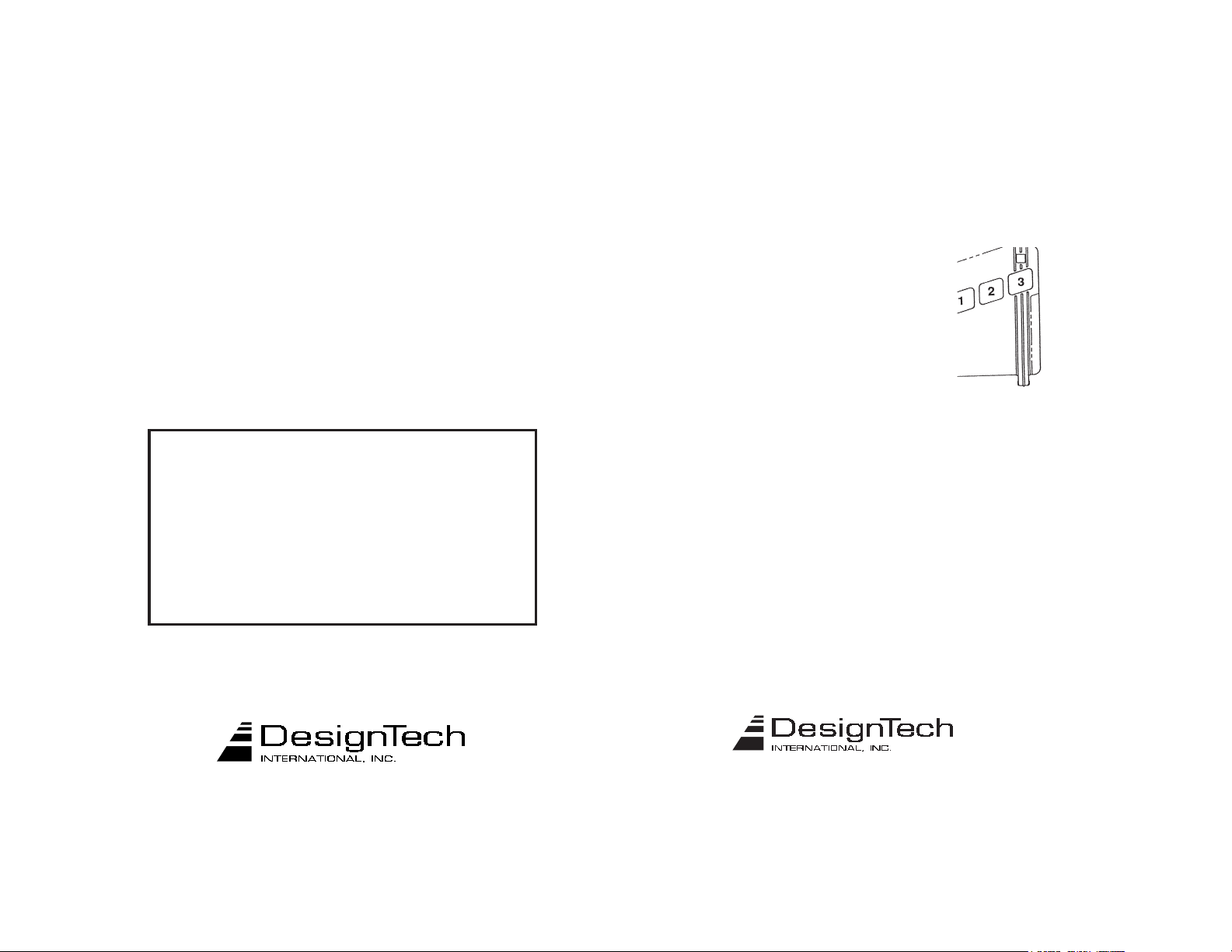
The transmitter button functions
are as follows:
Button 1:
Button 2: Once - Start the car with all accessories left on.
Again - Stop the car
Button 3: Once - Turn on the headlights for 25 seconds
The LED on the transmitter will display 3 different colors - Green for Button #1, Red
for Button #2, and Yellow for Button #3. The unit is powered by a long life lithium
battery. The transmitter and remote starter receiver module are FCC and DOC approved.
Important Note:
Make sure that all drivers who will be operating this unit are fully aware of the safety
precautions installed and their limitations. Stress the importance of switching the
control switch to OFF (the down position) every time the car is serviced. Show the
user how the Control switch must be turned off and on again after pulling out the key
before leaving the car. Give the user a copy of the tan colored page - USER TIPS AND
NOTES so that they can familiarize themselves with the product.
If further assistance is required, call our Tech Hotline. Please have model
number (20036, 20037 or 20038) and the diagnoistic code (See Step 28)
ready before calling tech support.
Once - Lock doors/arm alarm
Again - Unlock doors/disarm alarm
Hold for 2 seconds - Panic alarm (horn and lights)
Again - Turn off the headlights
Hold for 2 seconds -Pop Trunk / Unlock Doors /Disarm Alarm
7955 Cameron Brown Court; Springfield, Virginia 22153 USA
Tel: (703)866-2000 or (800)337-4468
www.designtech-intl.com
7955 Cameron Brown Court; Springfield, Virginia 22153 USA
Tel: (703)866-2000 or (800)337-4468
www.designtech-intl.com
28636 - 28638 Page 27Page 26 28636 - 28638
Page 15

LIMITED LIFETIME WARRANTY
DesignTech International, Inc. Warrants to the original consumer/purchaser that this
product shall be free of defects in material and workmanship under normal use and circumstances for the period of time that the original owner of this product owns the vehicle in
which it is installed. When the original consumer/purchaser returns the product pre-paid to
DesignTech International Inc., 7955 Cameron Brown Court, Springfield, Virginia 22153,
USA within the warranty period, and if the product is defective DesignTech International,
Inc. will at its option repair or replace such.
This warranty shall constitute the sole liability of DesignTech International, Inc. concerning the product. DesignTech International, Inc. expressly disclaims all other warranties
INCLUDING, WITHOUT LIMITATION, THE WARRANTIES OF MERCHANT ABILITY AND FITNESS FOR A PARTICULAR PURPOSE. NO PERSON, FIRM , OR CORPORATION IS AUTHORIZED TO ASSUME FOR DESIGNTECH INTERNATIONAL, INC.
ANY OTHER LIABILITY IN CONNECTION WITH THE SALE AND USE OF THE
PRODUCT. DesignTech International, Inc. and agents and distributors will bear no liability
whatsoever for incidental or consequential damages or charges of any kind.
Some states do not allow the exclusion or limitation of incidental or consequential damages,
so the above disclaimer regarding incidental or consequential damages may not apply to
you.
This warranty shall be effective only if the registration card is fully completed and mailed
with proof of purchase to: DesignTech International, Inc., 7955 Cameron Brown Court,
Springfield, Virginia 22153, USA within ten (10) days after date of purchase.
This warranty is void if the product or has been damaged or tampered with or if the product
or any such parts have been opened. In all cases of damage during shipment, a claim must
be filed with the shipping carrier and not with DesignTech International, Inc.
This warranty gives you specific legal rights; you may also have other rights which vary
from state to state.
If the warranty card was not returned, or if you are not the original owner of the vehicle the
product was installed in, DesignTech International, Inc. will at its option either (1) replace
this product with a functionally similar (but not necessarily visually identical) refurbished
product or (2) repair the original product and return it to the original consumer/purchaser
after payment of repair/replacement charges have been received.
This registration card must be returned within ten (10) days of purchase.
Name_________________________________________________________ User's Age_________
Address _________________________________________________________________________
City____________________________________ State__________________ Zip_______________
Phone Number: Home___________________________ Office______________________
Place of Purchase__________________________________ Date of Purchase________________
Product Purchased:____28636, ____37 or ____38 Price of Purchase:________
Vehicle Make:__________________Vehicle Model:________________Year:__________
This product was purchased for: ( ) Myself ( ) Spouse ( ) Relative ( ) Friend
How did you first become interested in this product?
( ) Retailer Newspaper Ad ( ) Magazine Ad ( ) In-Store Display
( ) Newspaper / Magazine Article ( ) Mail Order ( ) Friend / Relative
( ) In-Store Salesperson ( ) Other _____________________
__________ Please send me FREE information on other innovative DesignTech products
OUT OF WARRANTY REPAIRS
7955 Cameron Brown Court, Springfield, Virginia 22153, USA
Page 28 28636 - 28638
Tel: (703) 866-2000 Fax: (703)866-2001
 Loading...