

DesignTech AirWolf Installation Manual


2
v4.2
Before installing the system
Model #20096 basic model without Shock Sensor or Siren.
Model #20097 same as #20096 but with extra Valet (1-way) transmitter.
Model #20098 Complete with Shock Sensor and Siren.
Model #20099 same as #20098 but with extra Valet (1-way) transmitter.
Thank you for choosing DesignTech's AIRWOLF Two-Way Remote Car
Starter. The AIRWOLF units have been carefully designed and built with
customer convenience in mind. We encourage you to fully read this manual
before installing and using this system.
Caution
1. For installer and user safety, carefully read and understand this manual before
installation.
2. Have the system installed by an authorized dealer, or an experienced installer.
3. Several safety precautions for the installer/user:
- Do not attempt to remotely start the vehicle if it is in GEAR.
- Do not attempt to remotely start the vehicle if the ignition is on.
- Do not remotely start the vehicle if it is indoors or in a poorly ventilated area.
- Do not attempt to remotely start the vehicle if anyone is standing in front
or behind of the vehicle.
- Do not attempt remotely start the vehicle if anyone is inside of the vehicle.
- Always apply the parking brake and place the transmission in Park or Neutral.
4. If any problems occur, discontinue use and consult your dealer/installer for help.
On cars with airbags, you may notice bright yellow tubes or harnesses underneath the
steering column area. DO NOT tamper with these wires in any way, soas to prevent
personal injury and/or damage while working near the car's air bag system.
Battery gases are explosive. Do not smoke while working near the car's battery.
When working the wires through the car's firewall, be sure to protect them from sharp
metal edges and from hot surfaces on the engine.

3
v4.2
Contents
1. Use of DIP switch
2. Product wiring diagram
3. 6 Pin main harness (CON 1)
4. Signal output connector (CON 2)
5. Door control output connector (CON 3)
6. Valet switch (CON 4)
7. LED (CON 5)
8. Shock sensor (CON 6)
9. Trigger input connector (CON 7)
10. Programming the remote control
11. Programming for Tach / Voltage Sense
12. Configuring Function timing
13. Configuration summary table
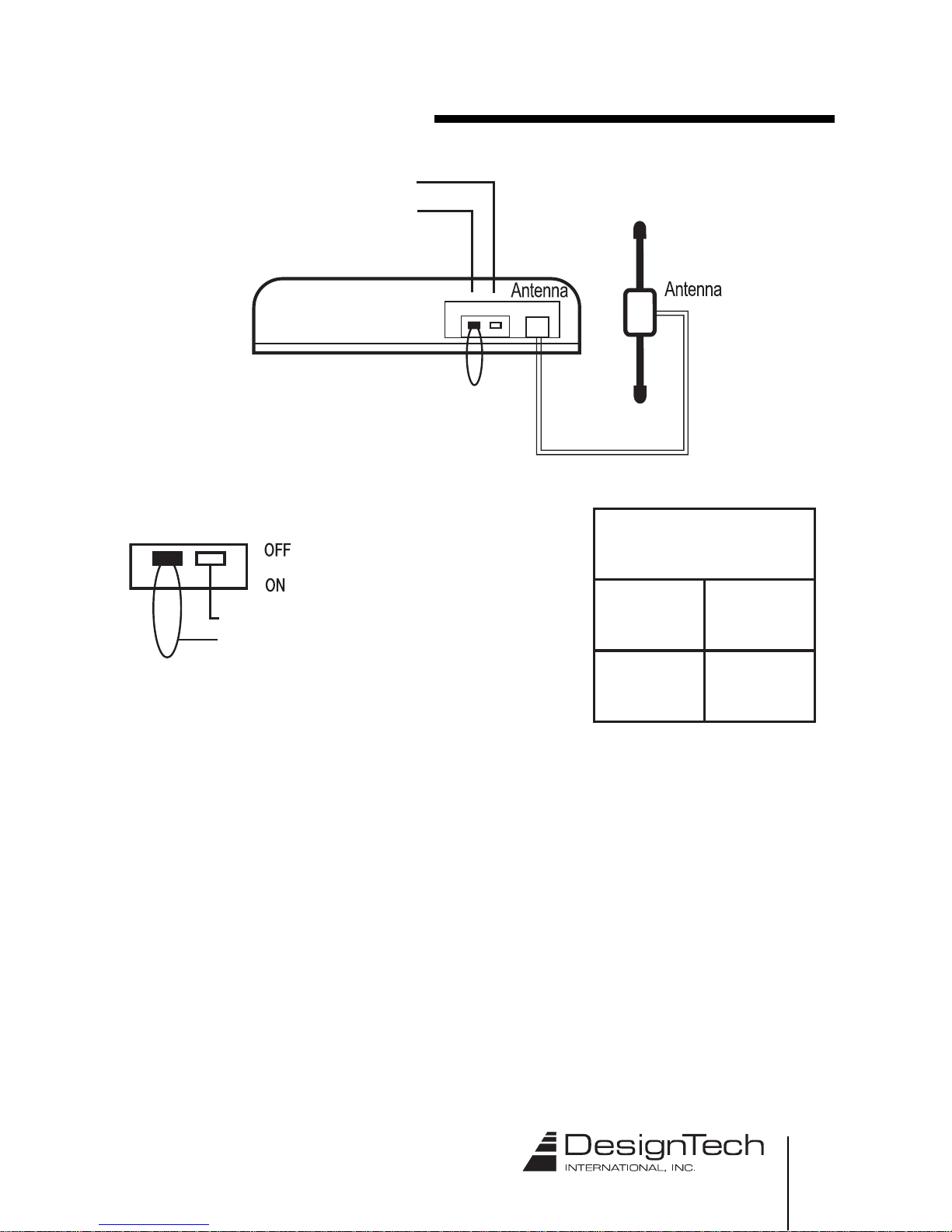
14. Antenna location
15. Relay diagram
5
6
8
10
14
18
18
18
19
23
24
26
30
30
31

4
v4.2
Precautions
■
Airwolf is designed to operate in a 12V system.
■ Always use a multimeter for checking wires. Test lights can trigger
airbags and damage circuits.
■ Check polarity of all circuits before making connections.
■
Always connect the ground wire (CON 1, black) before applying power
to the unit.
■ The tach wire and the siren wire should never be grounded,
or come in contact with chassis ground in any way.
■ Always use fuses when using external relays.
■ Designtech International is not responsible for damages or
injuries due to misuse or improper installation of the unit.
5
v4.2
1. Use of DIP switch / Loop
●
DIP Switch : Used in the programming of the Tach. signal. Set to Program when
learning Tach signal. Return to Operate (up position) after learning.
The hood and Dip Switch One are connected internally. Switch
One down = hood open. Switch one up = hood closed. Note that
when switch one is down the remote may indicate the hood is
open.
This unit is factory set for use with MANUAL TRANSMISSIONS. If
installing into a vehicle with an AUTOMATIC TRANSMISSION, Cut the
Manual / Automatic RED LOOP.
DIP Switch
Manual / Automatic Loop
DIP Switch
OFF
ON
Normal
Program
DIP Switch
Manual / Automatic Red Loop
6
v4.2
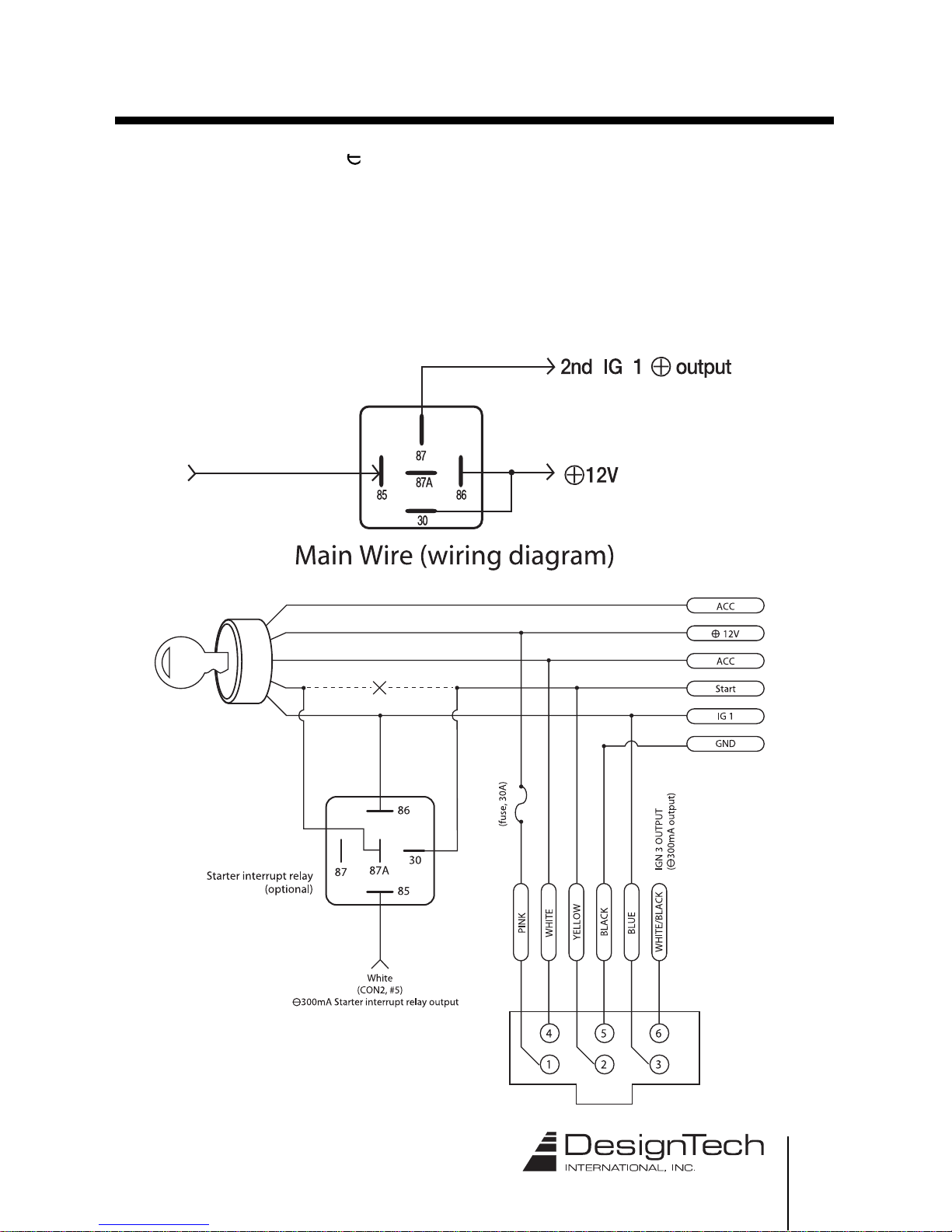
2. Overall wiring diagram
7
v4.2
8
v4.2
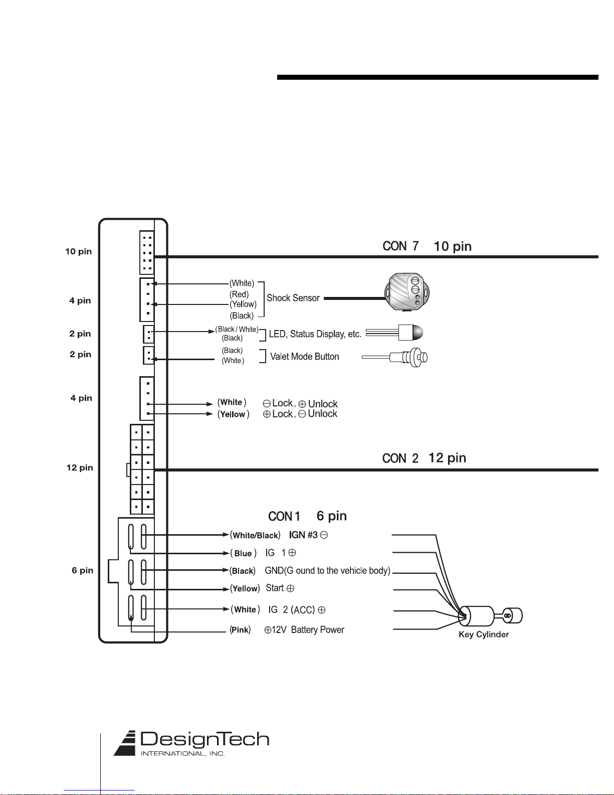
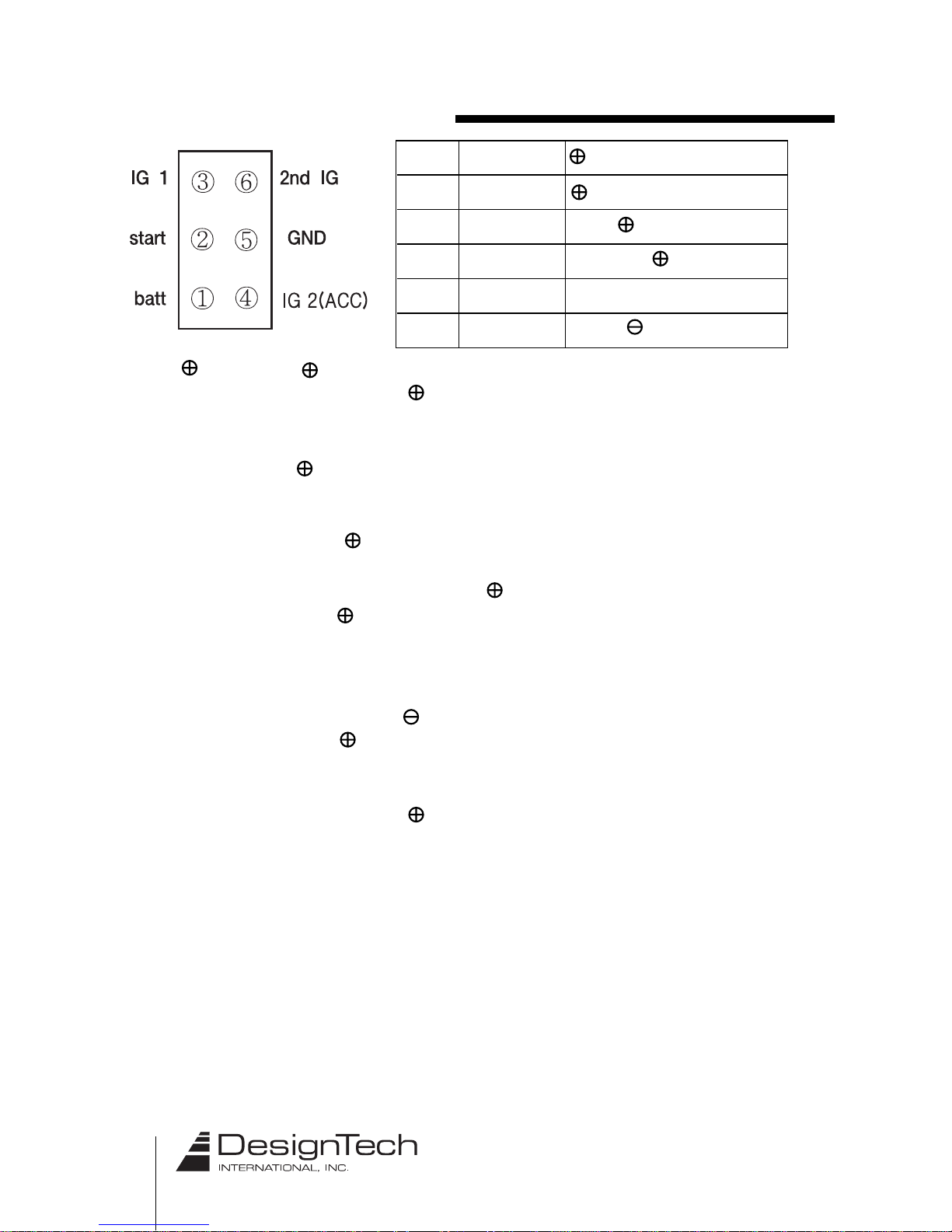
3. 6-pin main harness (CON1)
➀ Pink ( 12V): 12V main power input
Unit receives 12V from the car battery as the main power supply.
Connect this wire to the thickest wire in the ignition switch which
shows 12 volts regardless of the position of the key.
➁ Yellow (start): Output for starter motor. Connect this wire to the wire
in the vehicle's ignition switch that shows 12V only
when the starter is cranking.
➂ Blue ( IG 1): IGN 1 output
This wire will connect to a wire in the vehicle’s ignition switch
harness which shows 12 volts with the key in the run position
AND 12 volts when the key is in the crank position. The correct IGN
1 wire in the vehicle will not have power when the key is in the OFF
or ACC position. Note: You may have multiple wires which test as
described. If so, you may need to use a relay(s) and the White/Black
IGN 3 output to power the additional wire(s).
➃ White : ACC 12V output
In most installations this wire will power the vehicle heater/AC.
Connect this wire to the wire in the vehicle’s ignition switch harness
which shows 12 volts ONLY when the key is in the run position.
The correct wire will not have power with the key in the OFF, ACC,
or CRANK positions. If you have more than one wire which tests
as described you may need to use the IGN 2 (ACC) wire to power 2
or more relays - with each relay powering one wire in the vehicle.
Relays MUST be used to isolate the wires.
➄ Black (GND): Ground. Locate an area in the kick panel or against the firewall as
far from metal brackets or factory ground points as possible.
Using sandpaper (not included), remove the paint in an area
the size of a quarter. Using a self-tapping screw (not included),
securely connect the BLACK (GND) wire of the unit to the bare
metal spot you have created.
Pink
Yellow
Blue
White
Black
White/Black
12V main power input
output for start motor
IGN 1 output
IG 2 (ACC) 12V output
Ground Input
IGN 3
➅
➁
➀
➃
➂
➄
9
v4.2
White/Black IGN 3
➅ White /Black: IGN 3 output
This output is primarily used to control relays and bypass modules.
The ignition 3 output behaves exactly like ignition 1, except this
output provides a ground while running. Note: As this output is
connected internally to the ignition 1 relay a diode, such as Radio
Shacks 1n4001 (not included), may be needed to provide isolation if
any feedback problems occur.
10
v4.2
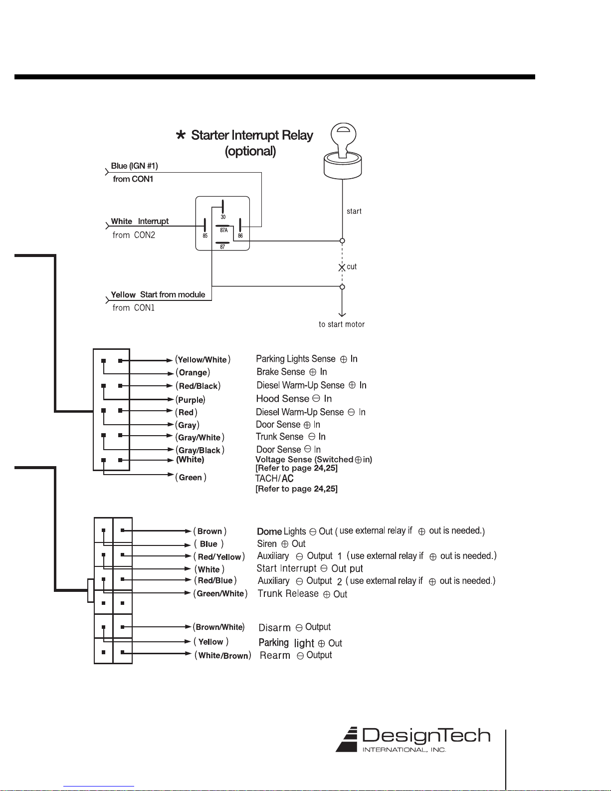
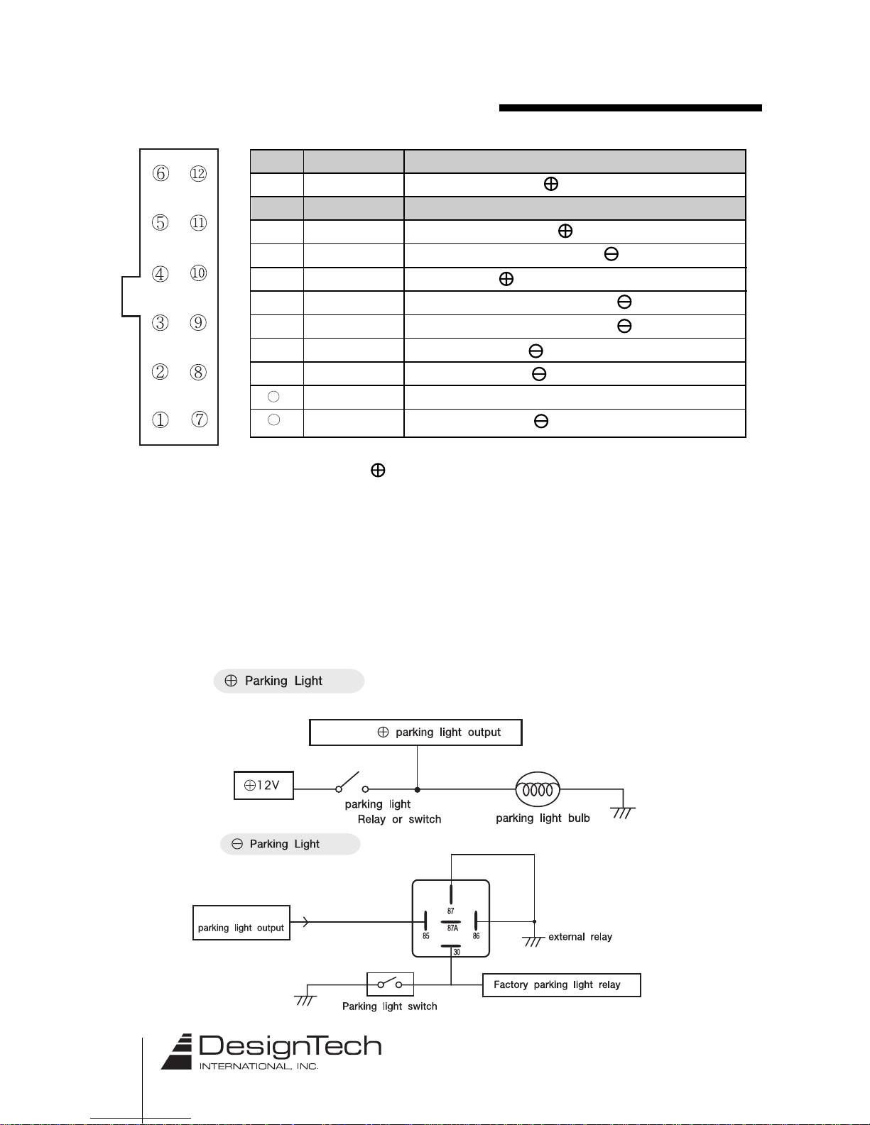
4. Signal output connector (CON 2 )
➀
➁
➂
➃
➄
➅
➆
➇
➈
➉
N/A
Yellow
N/A
Green/White
White
Blue
White/Brown
Brown/White
Red/Yellow
Red/Blue
N/A
Brown
Parking light output ( 10A relay)
Trunk Release output ( 10A relay)
Starter interrupt Signal output ( 300mA transistor)
Siren output ( 3A power transistor)
Rearm output for factory Alarm ( 300mA transistor)
disarm output for factory Alarm ( 300mA transistor)
Auxiliary 1 output ( 300mA transistor)
Auxiliary 2 output ( 300mA transistor)
Dome light output ( 300mA transistor)
➁ Yellow: Parking light output ( 10A relay)
Parking light output (max of 10A) Connect this wire to the
parking light wire in the vehicle. The correct wire in the vehicle will show 12
volts only when the parking lights are turned on. When the parking lights are
off the wire will show 0 volts. NOTE: In most cases connecting to one wire in
the vehicle will illuminate all parking lights. If not, there will be multiple wires
you need to power, isolating each wire with a relay. This is especially true in
European vehicles. Note: See the following diagram if your vehicle requires a
NEGATIVE trigger to illuminate the parking lights.
11
12
Yellow
type
Yellow
type
11
v4.2
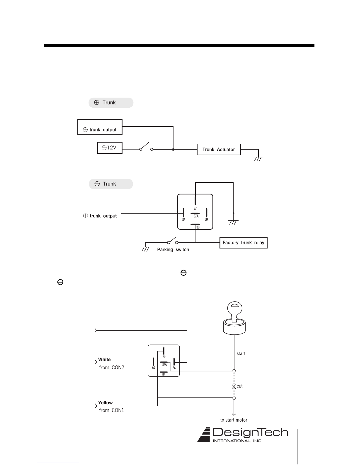
➃ Green/White: Trunk Release output ( 10A relay)
This output provides a positive signal when the “Trunk Release”
is activated. Refer to the following diagrams for proper connection.
➄ White : Starter Interrupt Signal output ( 300 mA transistor)
The 300mA output is used to disable starter via an external relay.
Green/White
type
Starter Interrupt Relay
*
Blue (IGN #1)
from CON1
Interrupt
Start from module
(not included)
Green/White
type
 Loading...