

Page 1
ARL LOGO
G 004
®
TRADESMAN K70 & KI55
KEROSENE
PORTABLE FORCED
AIR HEATERS
(WITH BUILT-IN THERMOSTAT)
OWNER’S MANUAL
Models: CP070BK and CP155CK
Heater Size: 70,000 and 155,000 Btu/Hr
H.S.I. Series
IMPORTANT: Read and understand this manual before assembling, starting, or servicing
heater. Improper use of heater can cause serious injury. Keep this manual for future reference.
TABLE OF CONTENTS
SAFETY INFORMATION ............................................................ 2
PRODUCT IDENTIFICATION ..................................................... 3
UNPACKING............................................................................... 3
THEORY OF OPERATION ......................................................... 4
FUELS......................................................................................... 4
VENTILATION............................................................................. 4
ASSEMBLY................................................................................. 5
OPERATION ............................................................................... 5
OPERATION WITH PORTABLE GENERATOR.......................... 6
PREVENTATIVE MAINTENANCE SCHEDULE ......................... 6
STORING, TRANSPORTING, OR SHIPPING............................ 6
TROUBLESHOOTING ................................................................ 7
SERVICE PROCEDURES .......................................................... 8
WIRING DIAGRAM ................................................................... 14
SPECIFICATIONS .................................................................... 14
TECHNICAL SERVICE ............................................................. 15
REPLACEMENT PARTS .......................................................... 15
ACCESSORIES ........................................................................ 15
ILLUSTRATED PARTS BREAKDOWN AND PARTS LIST ....... 16
WARRANTY AND GENERAL INFORMATION ......................... 22
Page 2
SAFETY INFORMATION
2
SAFETY INFORMATION
WARNINGS
WARNING: This product contains and/or generates
chemicals known to the State of California to cause
cancer or birth defects, or other reproductive harm.
IMPORTANT: Read this owner’s manual carefully and
completely before trying to assemble, operate, or service this heater. Improper use of this heater can cause
serious injury or death from burns, fire, explosion,
electrical shock, and carbon monoxide poisoning.
DANGER: Carbon monoxide poisoning may lead
to death!
Carbon Monoxide Poisoning: Early signs of carbon monoxide
poisoning resemble the flu, with headaches, dizziness, and/or nausea. If you have these signs, the heater may not be working properly.
Get fresh air at once! Have heater serviced. Some people are more
affected by carbon monoxide than others. These include pregnant
women, persons with heart or lung disease or anemia, those under
the influence of alcohol, and those at high altitudes.
Make certain you read and understand all warnings. Keep this
manual for reference. It is your guide to safe and proper operation
of this heater.
• Use only kerosene, #1#2 diesel/fuel oil, JET A or JP-8 fuels to
avoid risk of fire or explosion. Never use gasoline, naphtha,
paint thinners, alcohol, or other highly flammable fuels.
• Fueling
a)Personnel involved with fueling shall be qualified and thor-
oughly familiar with the manufacturer's instructions and applicable regulations regarding the safe fueling of heating units.
b)Only the type of fuel specified on the heater's data plate shall
be used.
c) All flame, including the pilot light, if any, shall be extin-
guished and the heater allowed to cool, prior to fueling.
d)During fueling, all fuel lines and fuel-line connections shall
be inspected for leaks. Any leaks shall be repaired prior to
returning the heater to service.
e)At no time shall more than one day's supply of heater fuel
be stored inside a building in the vicinity of the heater. Bulk
fuel storage shall be outside the structure.
f) All fuel storage shall be located a minimum of 762cm (25
feet) from heaters, torches, welding equipment, and similar
sources of ignition (exception: the fuel reservoir integral with
the heater unit).
g)Whenever possible, fuel storage shall be confined to areas
where floor penetrations do not permit fuel to drip onto or
be ignited by a fire at lower elevation.
h)Fuel storage shall be in accordance with the authority hav-
ing jurisdiction.
• Use only the electrical voltage and frequency specified on
model plate.
• Heater must be grounded. Use only a properly grounded threewire extension cord. Plug into grounded outlet only.
• Use only in areas free of flammable vapors or high dust content.
• Minimum clearance from any combustible materials: 8 feet (244
cm) from hot air outlet; 4 feet (122 cm) from top; and 4 feet
(122 cm) from sides and inlet.
• Locate heater on a stable and level surface while hot or operating or a fire may occur.
• Use only in well-vented areas. Before using heater, provide at
least a 2800 square cm (three-square-foot) opening of fresh,
outside air for each 30 kw (100,000 Btu/Hr) of rating.
• Keep children and animals away from heater at all times.
• Never start heater when combustion chamber is hot or if fuel
has accumulated in combustion chamber.
• When used with thermostat, heater may start at anytime.
• When heater is moved or stored, it must be in a level position
or fuel spillage may occur.
• Use heater only in accordance with local ordinances and codes.
• Never use gasoline, crankcase drainings, naphtha, paint
thinners, alcohol, or other highly flammable fuels.
• Never use heater where gasoline, paint thinner, or other highly
flammable vapors are present.
• Never use heater in living or sleeping areas.
• Never leave a heater plugged in without adult supervision if
children or animals are likely to be present.
• Never move, handle, refuel, or service a hot, operating, or
plugged-in heater.
• Never attach duct work to front or rear of heater.
• Never attach heater to external fuel tank.
• Heaters used in the vicinity of tarpaulins, canvas, or similar
enclosure materials shall be located a safe distance from such
materials. The recommended minimum safe distance is
304.8cm (10 feet). It is further recommended that these enclosure materials be of a fire retardant nature. These enclosure
materials shall be securely fastened to prevent them from igniting or from upsetting the heater due to wind action.
• Unplug heater when not in use.
• Never block air inlet (rear) or air outlet (front) of heater.
•
Warning to New York City Residents
For Use Only At Construction Sites in accordance with ap-
plicable NYC codes under NYCFD certificate of approval
#4803, #4899, #4908, #4909, or #4934.
111178-01A
Page 3
PRODUCT IDENTIFICATION
UNPACKING
3
3
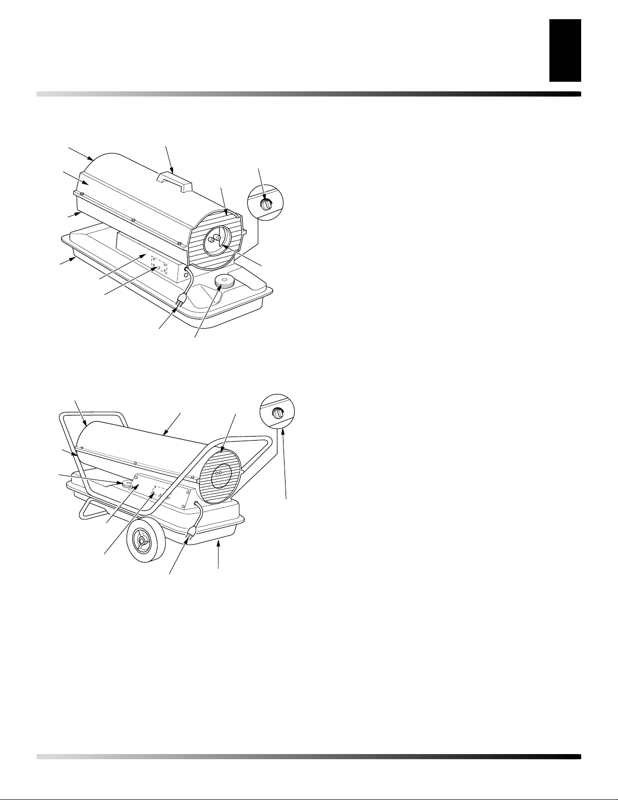
PRODUCT IDENTIFICATION
Hot Air
Outlet
Upper
Shell
Lower
Shell
Fuel
Tank
Side Cover
Ignition Control
Assembly (On Inside
of Side Cover)
Figure 1 - 70,000 Btu Unit
Hot Air Outlet
Handle
Power
Cord
Upper Shell
Thermostat Knob
(Thermostat Models Only)
Fan Guard
Air Filter
End
Cover
Fuel Cap
Fan
Guard
UNPACKING
1. Remove all packing items applied to heater for shipment.
2. Remove all items from carton.
3. Check items for shipping damage. If heater is damaged,
promptly inform dealer where you bought heater.
Lower
Shell
Fuel
Cap
Side Cover
Ignition Control
Assembly (On Inside
of Side Cover)
Figure 2 - 155,000 Btu Unit
Power Cord
Thermostat
Knob
(Thermostat
Models Only)
Fuel Tank
111178-01A
Page 4
THEORY OF OPERATION
4
FUELS
VENTILATION
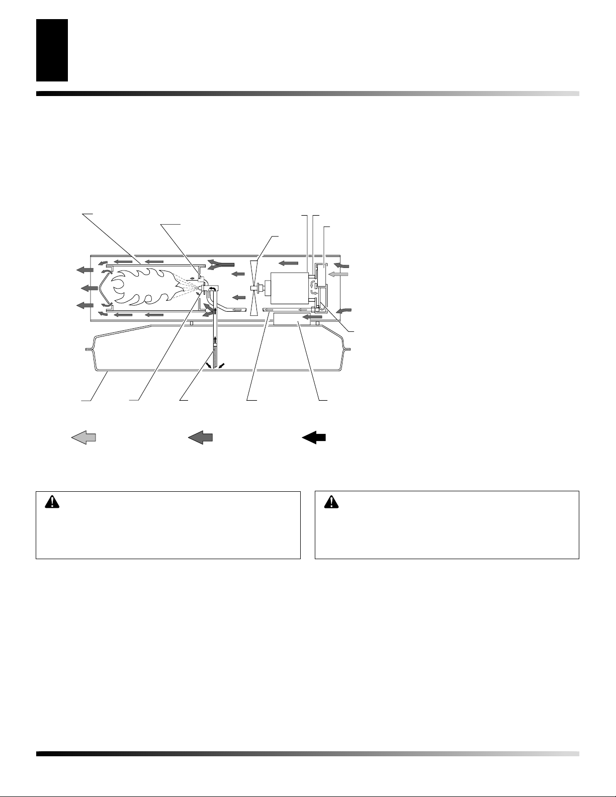
THEORY OF OPERATION
The Fuel System: The air pump forces air through the air line. The
air is then pushed through the nozzle. This air causes fuel to lift from
the tank. A fine mist of fuel is sprayed into the combustion chamber.
The Air System: The motor turns the fan. The fan pushes air into
and around the combustion chamber. This air is heated and provides
a stream of clean, hot air.
Clean
Heated
Air Out
Fuel
Tank
Combustion Chamber
Nozzle
Air For Fuel System
Ignitor
Fuel
Filter
Air For Combustion
And Heating
Motor
Fan
Air Line
To Burner
The Ignition System:
The ignition control assembly provides
power to the ignitor. This ignites the fuel/air mixture in the combustion chamber.
The Flame-Out Control System: This system causes the heater to
shut down if the flame goes out.
Air Pump
Air Intake
Filter
Cool
Air
In
Air
Output
Filter
Ignition Control
Assembly
Fuel
Figure 3 - Cross Section Operational View
FUELS
WARNING: Use only kerosene, #1/#2 diesel/fuel
oil, JET A or JP-8 fuels to avoid risk of fire or explosion. Never use gasoline, oil drained from crankcases, naphtha, paint thinners, alcohol or other highly
flammable fuels.
Use only kerosene, #1/#2 diesel/fuel oil, JET A or JP-8 fuels.
Heavier fuels such as No. 2 fuel oil or No. 2 diesel fuel may also be
used but will result in:
• noticeable odor
• additional fuel filter maintenance
• the need for nontoxic, anti-icer additives in very cold weather
Do not use fuels heavier than No. 2 grade or heavy oils such as oil
drained from crankcases. These heavy oils will not ignite properly
and will contaminate the heater.
IMPORTANT:
(yellow) storage container. Be sure storage container is clean. Foreign
matter such as rust, dirt, or water will cause the ignition control
assembly to shut down the heater. Foreign matter may also require
heater's fuel system to be frequently cleaned.
Use a KEROSENE ONLY (blue) or DIESEL ONLY
VENTILATION
Follow the minimum fresh, outside air ventilation
requirements. If proper fresh, outside air ventilation
is not provided, carbon monoxide poisoning can
occur. Provide proper fresh, outside air ventilation
before running heater.
Provide at least a three-square-foot opening of fresh, outside air for
each 100,000 Btu/Hr rating. Provide extra fresh air if more heaters
are being used.
Example:
• a two-car garage door (16 feet wide opening) raised 3.5 inches
• a single-car garage door (9 feet wide opening) raised 6.5 inches
• two 30 inch wide windows raised 11.5 inches
A 155,000 Btu/Hr heater requires one of the following:
111178-01A
Page 5
ASSEMBLY
OPERATION
5
5
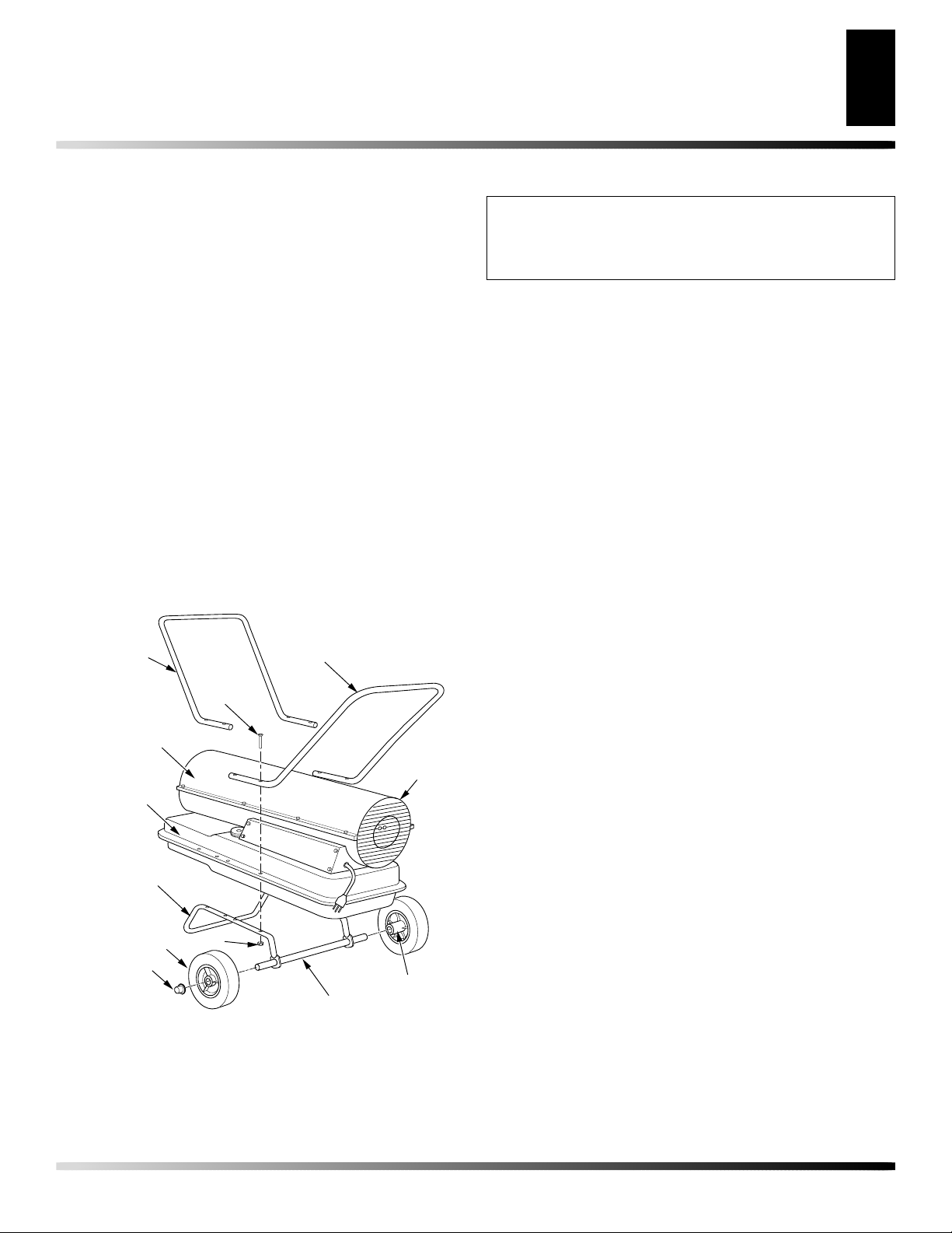
ASSEMBLY
(155,000 BTU UNITS ONLY)
This model is furnished with wheels and handles. Wheels, handles,
and the mounting hardware are found in the shipping carton.
TOOLS NEEDED
• Medium Phillips Screwdriver
• 3/8" Open or Adjustable Wrench
• Hammer
1. Slide axle through wheel support frame. Install wheels on axle.
IMPORTANT:
of wheels toward wheel support frame (see Figure 4).
2. Place cap nuts on axle ends. Gently tap with hammer to secure.
3. Place heater on wheel support frame. Make sure air inlet end
(rear) of heater is over wheels. Line up holes on fuel tank
flange with holes on wheel support frame.
4. Place front handle (and rear handle if provided) on top of
fuel tank flange. Insert screws through handle(s), fuel tank
flange, and wheel support frame. Attach nut finger tight after
each screw is inserted.
5. After all screws are inserted, tighten nuts firmly.
Front Handle
(If Provided)
Hot Air
Outlet
Fuel Tank
Flange
When installing wheels, point extended hub
Handle
Screw
Air
Inlet
OPERATION
IMPORTANT: Review and understand the warnings
in the
needed to safely operate this heater. Follow all local
ordinances and codes when using this heater.
TO START HEATER
1. Follow all ventilation and safety information.
2. Locate heater to provide maximum circulation of the heated
3. Fill fuel tank with kerosene, #1#2 diesel/fuel oil, JET A or
4. Attach fuel cap.
5. For thermostat models, turn thermostat knob clockwise to the
6. Plug heater’s power cord into approved, grounded, three-wire
7. Plug extension cord into standard 120 volt/60 hertz, 3-prong
8. For thermostat models, adjust thermostat knob to the desired
Safety Information
air. Follow all location requirements noted in Safety Information, page 2.
JP-8 fuel.
high position.
extension cord. Extension cord must be at least six feet (1.8
meters) long.
Extension Cord Size Requirement
6 to 10 feet (1.8 to 3 meters) long, use 18 AWG (0.75 mm2)
rated cord
11 to 100 feet (3.3 to 30.5 meters) long, use 16 AWG (1.0 mm2)
rated cord
101 to 200 feet (30.8 to 61 meters) long, use 14 AWG (1.5 mm2)
rated cord
grounded outlet.
then heater will start.
setting.
This thermostat is a general-heating control. It is not intended
for precise temperature control. Adjust thermostat until heater
cycles at the desired setting.
Note:
Note:
A cold heater may affect the thermostat setting.
section, page 2. They are
Ignitor will preheat for five seconds,
Wheel
Support
Frame
Wheel
Cap Nut
Figure 4 - Wheel and Handle Assembly
111178-01A
Nut
Axle
Extended
Hub
TO STOP HEATER
Unplug extension cord from outlet.
TO RESTART HEATER
1. Unplug extension cord from outlet and wait 10 seconds. (W ait
two minutes if heater has been running.)
2. Repeat steps under To Start Heater.
Page 6
OPERATION WITH PORTABLE GENERATOR
6
PREVENTATIVE MAINTENANCE SCHEDULE
STORING, TRANSPORTING, OR SHIPPING
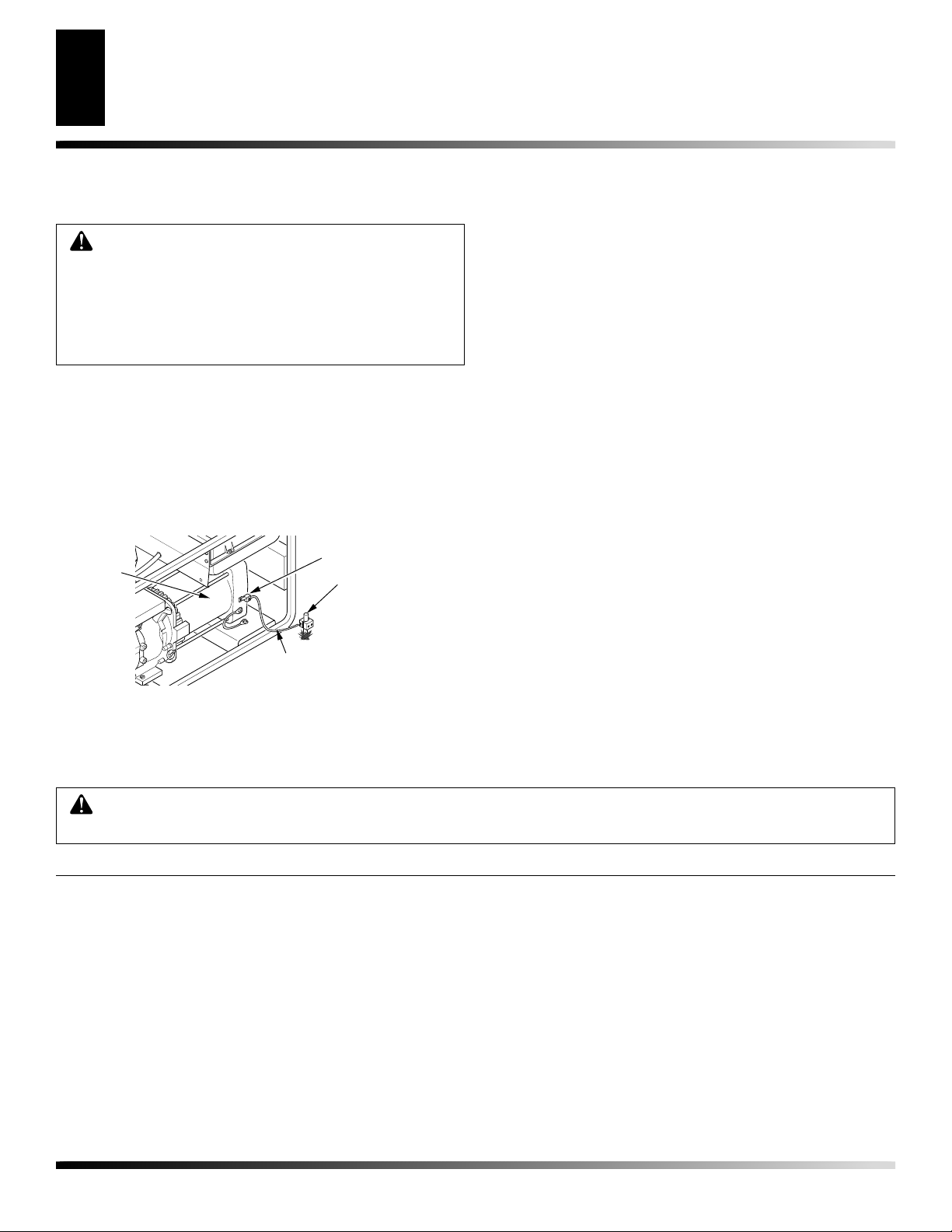
OPERATION WITH PORTABLE
GENERATOR
WARNING: Before operating heater or any appliance from a portable generator, verify that generator
has been properly connected to earth ground. Improper grounding or failure to ground generator can
result in electrocution if a ground fault occurs. Refer
to owner’s manual supplied by generator manufacturer for proper grounding procedures.
The operating voltage range of the heater is 108 to 132 Volts (120
Volts +/- 10%). Prior to plugging heater into generator the output
voltage should be verified (if generator is equipped with the automatic idle feature, the output voltage should be measured with the
generator running at full speed). If the voltage does not measure in
this range the heater should not be plugged into the generator.
Refer to Operation, page 5, for starting, stopping, and resetting
heater procedures.
Alternator
Ground Lug
Copper or Brass
Grounding Point
STORING, TRANSPORTING,
OR SHIPPING
Note:
If shipping, transport companies require fuel tanks to be empty.
1. Drain fuel tank.
Note:
Some models have drain plug on underside of fuel tank.
If so, remove drain plug to drain all fuel. If heater does not
have drain plug, drain fuel through fuel cap opening. Be sure
all fuel is removed.
2. Replace drain plug if provided.
3. If any debris is noted in old fuel, add 1 or 2 quarts of clean
kerosene to tank, stir, and drain again. This will prevent excess
debris from clogging filters during future use.
4. Replace fuel cap or drain plug. Properly dispose of old and
dirty fuel. Check with local automotive service stations that
recycle oil.
5. If storing, store heater in dry place. Make sure storage place is
free of dust and corrosive fumes.
IMPORTANT:
during next heating season. Using old fuel could damage heater.
Do not store kerosene over summer months for use
Ground Wire (#10 AWG Stranded-Copper)
Figure 5 - Typical Generator Grounding Method (Generator
construction may vary from that shown)
PREVENTATIVE MAINTENANCE SCHEDULE
WARNING: Never service heater while it is plugged in, operating, or hot. Severe burns and electrical shock
can occur.
Item
Fuel tank
Air output and lint filters
Air intake filter
Fuel filter
Ignitor
Fan blades
How Often
Flush every 150-200 hours of operation or as needed
Replace every 500 hours of operation or once a year
Wash and dry with soap and water every 500 hours
of operation or as needed
Clean twice a heating season or as needed
No maintenance required
Clean every season or as needed
How To
See Storing, Transporting, or Shipping, above
See Air Output, Air Intake, and Lint Filters, page 8
See Air Output, Air Intake, and Lint Filters, page 8
See Fuel Filter, page 9
See Fan, page 8
Motor
Not required/permanently lubricated
111178-01A
Page 7
TROUBLESHOOTING
7
7
TROUBLESHOOTING
OBSERVED FAULT
Motor does not start five seconds after heater
is plugged in
Motor starts and runs but heater does not
ignite
WARNING: Never service heater while it is plugged in, operating,
or hot. Severe burns and electrical shock can occur.
POSSIBLE CAUSE
1. No power to heater
2. Thermostat setting too low
WARNING: High voltage!
3. Bad electrical connection between motor and ignition control assembly or ignition control assembly and power cord
4. Blown fuse on ignition control assembly
5. Binding pump rotor
6. Defective ignition control assembly
7. Defective motor
1. No fuel in tank
2. Pump pressure incorrect
3. Dirty fuel filter
4. Obstruction in nozzle assembly
5. Water in fuel tank
REMEDY
1. Check circuit breaker in electrical panel.
2. Turn thermostat knob to a higher setting
3. Check all electrical connections. See
Wiring Diagram, page 14
4. See Ignition Control Assembly, page 13
5. If fan does not turn freely, see Pump
Rotor, page 12
6. Replace ignition control assembly
7. Replace motor
1. Fill tank with kerosene
2. See Pump Pressure Adjustment, page 9
3. See Fuel Filter, page 9
4. See Nozzle Assembly, page 11
5. Drain and flush fuel tank with clean kerosene. See Storing, Transporting, or Ship-
ping, page 6
Heater ignites but ignition control assembly
shuts heater off after a short period of time
WARNING: High voltage!
6. Bad electrical connection between ignitor and ignition control assembly
7. Defective ignitor
8. Defective ignition control assembly
1. Pump pressure incorrect
2. Dirty air intake, air output, and/or lint
filter
3. Dirty fuel filter
4. Obstruction in nozzle assembly
5. Photocell assembly not properly installed
(not seeing the flame)
WARNING: High voltage!
6. Dirty photocell lens
7. Bad electrical connection between photocell and ignition control assembly
8. Defective photocell
9. Defective ignition control assembly
6. Check electrical connections. See Wir-
ing Diagram, page 14
7. Replace ignitor, see page 10
8. Replace ignition control assembly
1. See Pump Pressure Adjustment, page 9
2. See Air Output, Air Intake, and Lint Fil-
ters, page 8
3. See Fuel Filter, page 9
4. See Nozzle Assembly, page 11
5. Make sure photocell boot is properly
seated in bracket
6. Clean photocell lens
7. Check electrical connections. See Wir-
ing Diagram, page 14
8. Replace photocell
9. Replace ignition control assembly
111178-01A
Page 8

SERVICE PROCEDURES
8
SERVICE PROCEDURES
WARNING: To avoid risk of burn and electrical
shock, never attempt to service heater while it is
plugged in, operating, or hot.
Setscrew
Fan
Motor
Setscrew
Fan
UPPER SHELL REMOVAL
1. Remove screws along each side of heater using 5/16" nut-driver.
These screws attach upper and lower shells together. See Figure 6 or 7.
2. Lift upper shell off.
3. Remove fan guard.
Screw
Upper Shell
Fan
Guard
Figure 6 - Upper Shell
Removal, 70,000 Btu Units
Figure 7 - Upper Shell
Removal, 155,000 Btu Units
Screw
Upper Shell
Fan
Guard
FAN
IMPORTANT:
motor from heater. The weight of the motor resting on the fan could
damage the fan pitch (see Figure 8).
1. Remove upper shell (see Figure 6 or 7).
2. Use 1/8" allen wrench to loosen setscrew which holds fan to
motor shaft.
3. Slip fan off motor shaft.
4. Clean fan using a soft cloth moistened with kerosene or solvent.
5. Dry fan thoroughly .
6. Replace fan on motor shaft. Place fan hub flush with end of
motor shaft (see Figure 9).
7. Place setscrew on flat of shaft. Tighten setscrew firmly (40-50
inch-pounds).
8. Replace fan guard and upper shell.
Remove fan from motor shaft before removing
Flush
Motor
Shaft
Figure 8 - Fan, Motor Shaft,
and Setscrew Location
Figure 9 - Fan Cross Section
Motor
Shaft
AIR OUTPUT, AIR INTAKE AND LINT FILTERS
1. Remove upper shell (see Figure 6 or 7).
2. Remove filter end cover screws using 5/16" nut-driver (see Figure 10 or 11).
3. Remove filter end cover.
4. Replace air output and lint filters.
5. W ash or replace air intake filter (see Pre ventative Maintenance
Schedule, page 6).
6. Replace filter end cover.
7. Replace fan guard and upper shell (see Figure 6 or 7).
IMPORTANT:
Lint Filter
Figure 10 - Air Output, Air Intake, and Lint Filters, 70,000 Btu Units
Do not oil filters.
Air Output
Filter
Lint Filter
Air Intake
Filter
Air Intake
Filter
Filter End
Cover
Filter End
Cover
Air Output Filter
Figure 11 - Air Output, Air Intake, and Lint Filters, 155,000 Btu Units
111178-01A
Page 9

SERVICE PROCEDURES
Continued
SERVICE PROCEDURES
9
9
PUMP PRESSURE ADJUSTMENT
1. Remove pressure gauge plug from filter end cover.
2. Install accessory pressure gauge (part number 500-20907).
3. Start heater (see Operation, page 5). Allow motor to reach
full speed.
4. Using a flat blade screwdriver, adjust pressure. T urn relief valve
to right to increase the pressure. Turn relief valve to left to
decrease the pressure.
Correct pump pressures:
• 70,000 unit: 4.7 PSI
• 155,000 unit: 5.2 PSI
5. Stop heater (see Operation, page 5).
6. Remove pressure gauge. Replace pressure gauge plug in filter
end cover.
Relief
Valve
Pressure
Gauge
Plug
Fuel Filter
and Bushing
Upper Fuel Line
Side Cover
Figure 14 - Fuel Filter Removal, 70,000 Btu Units
Fuel Filter, Bushing,
and Lower Fuel Line
Figure 12 - Pressure Gauge Plug Removal
Pressure
Gauge
Figure 13 - Adjusting Pump Pressure
FUEL FILTER
1. Remove side cover screws using 5/16" nut-driver.
2. Remove side cover.
3. Pull upper fuel line off fuel filter neck (see Figure 14 or 15).
4. Carefully pry bushing, fuel filter, and lower fuel line out of
fuel tank (see Figure 14 or 15).
5. Wash fuel filter with clean fuel and replace in tank.
6. Attach upper fuel line to fuel filter neck.
7. Replace side cover.
Side
Cover
Upper Fuel Line
Figure 15 - Fuel Filter Removal, 155,000 Btu Units
111178-01A
Page 10

10
SERVICE PROCEDURES
SERVICE PROCEDURES
Continued
IGNITOR
1. Remove upper shell and fan guard (See Upper Shell Removal,
page 8).
2. Remove fan (see page 8).
3. Remove 4 side cover screws with a 5/16" nut driver. Remove
side cover (see Figures 14 or 15, page 9).
4. Disconnect ignitor wires (yellow) from ignition control assembly (see Figure 16). Pull the ignitor wires up through
the hole in the lower shell.
5. Disconnect fuel line hose and air line hose. Remove photocell
from photocell bracket (see Figure 16).
6. Remove combustion chamber. Stand combustion chamber on
end with nozzle adapter bracket on top (see Figure 17).
7. Remove ignitor screw with a 1/4" nut driver. Carefully remove
ignitor from nozzle adapter bracket.
CAUTION: Do not bend or strike ignitor element.
Handle with care.
Nozzle Adapter
Combustion
Chamber
Bracket
8. Carefully remove replacement ignitor from styrofoam packing.
9. Carefully guide ignitor into opening in nozzle adapter bracket.
Do not strike ignitor element. Attach ignitor to nozzle adapter
bracket with screw using a 1/4" nut driver (see Figure 17).
T orque 8 to 15 in. lbs. Do not over torque.
10. Replace combustion chamber.
11. Route the ignitor wires back down through the hole in the lower
shell. Connect wires to the ignition control assembly (see Figure 16).
12. Replace side cover (see Figures 14 or 15, page 9).
13. Connect and route fuel line hose and air line hose to nozzle
adapter assembly. See Fuel and Air Line Replacement and
Proper Routing, page 12.
14. Replace photocell in photocell bracket. Route wires as shown in
either (see Figure 18 or 19, page 11).
15. Replace fan (see page 8).
16. Replace fan guard and upper shell (see page 8).
Ignitor Screw/
Washer Assembly
Ignitor
Ignitor
Air Line Hose
Ignitor Wire
Fuel Line Hose
Photocell
Bracket
Photocell
Assembly
Side Cover
Figure 16 - Disconnecting Ignitor Wires from Ignition Control
Assembly
Ignition
Control
Assembly
Ignitor Element
Photocell
Bracket
Combustion
Chamber
Figure 17 - Ignitor Replacement
Nozzle Adapter
Bracket
Nozzle Adapter
Bracket Opening
111178-01A
Page 11

SERVICE PROCEDURES
Continued
SERVICE PROCEDURES
11
11
NOZZLE ASSEMBLY
1. Remove upper shell (see Upper Shell Removal, page 8).
2. Remove fan (see Fan, page 8).
3. Remove fuel and air line hoses from nozzle assembly (see Figure 18 or 19).
4. Turn nozzle assembly 1/4 turn to left and pull toward motor to
remove (see Figure 20).
5. Place plastic hex-body into vise and lightly tighten.
6. Carefully remove nozzle from the nozzle adapter using 5/8"
socket wrench (see Figure 21).
7. Blow compressed air through face of nozzle. This will free
any dirt in nozzle area.
8. Inspect nozzle sleeve for damage.
9. Replace nozzle into nozzle adapter until nozzle seats. Tighten
1/3 turn more using 5/8" socket wrench (40 to 45 inch-pounds).
See Figure 21.
10. Attach nozzle assembly to burner strap (see Figure 20).
11. Attach fuel and airline hoses to nozzle assembly. See Fuel and
Airline Replacement and Proper Routing, page 12.
12. Replace fan (see Fan, page 8).
13. Replace fan guard and upper shell (see Upper Shell Removal,
page 8).
Combustion
Chamber
Nozzle
Adapter
Bracket
Photocell
Bracket
Air Line
Hose
Figure 19 - Removing Air and Fuel Line Hoses, 155,000 Btu Units
Combustion
Chamber
Nozzle/
Adapter
Assembly
Fuel Line Hose
Nozzle/Adapter
Assembly
Combustion
Chamber
Nozzle
Adapter
Bracket
Photocell
Bracket
Air Line
Hose
Figure 18 - Removing Air and Fuel Line Hoses, 70,000 Btu Units
Nozzle/Adapter
Assembly
Fuel Line Hose
Figure 20 - Removing Nozzle/Adapter Assembly
Nozzle
Face
Nozzle
Nozzle Adapter
Figure 21 - Nozzle and Nozzle Adapter
Nozzle Sleeve
Air Line
Fitting
Fuel Line
Fitting
111178-01A
Page 12

12
SERVICE PROCEDURES
SERVICE PROCEDURES
Continued
FUEL AND AIR LINE REPLACEMENT AND
PROPER ROUTING
1. Remove upper shell (see page 8).
2. Remove side cover screws using 5/16" nut driver.
3. Remove side cover.
4. Inspect fuel and air line hoses for cracks and/or holes. If fuel
line hose is damaged, disconnect from nozzle adapter (see
Figure 18 or 19, page 11) and from fuel filter (see Figure 14
or 15, page 9). If air line hose is damaged, disconnect from
nozzle adapter (see Figure 18 or 19, page 11) and from barb
fitting on pump end cover (see Figure 22).
5. Install new air and/or fuel line. Attach one end of air line hose
to barb fitting on pump end cover (see Figure 22) and the other
end to nozzle adapter (see Figure 18 or 19, page 11). Attach
one end of fuel line hose to fuel filter (see Figure 14 or 15,
page 9) and the other end to nozzle adapter (see Figure 18 or
19, page 11). Route air and fuel line approximately as shown
in either Figure 18 or 19, page 11.
Note:
Hoses are not to be touching photocell bracket.
6. Replace side cover.
7. Replace upper shell and fan guard (see page 8).
Pump End Cover
PUMP ROTOR
(Procedure if Rotor is Binding)
1. Remove upper shell (see page 8).
2. Remove filter end cover screws using 5/16" nut-driver.
3. Remove filter end cover and air filters (see Figure 23 or 24).
4. Remove pump plate screws using 5/16" nut-driver.
5. Remove pump plate.
6. Remove rotor, insert, and blades.
7. Check for debris in pump. If debris is found, blow out with
compressed air.
8. Install insert and rotor.
Blade
Pump Plate
Air Intake Filter
Filter End
Cover
Insert
Rotor
Air Hose
Figure 22 - Air Hose to Barb Fitting
Barb Fitting
Air Output
Filter
Figure 23 - Rotor Location, 70,000 Btu Units
Blade
Pump Plate
Air Intake Filter
Filter End
Cover
Insert
Rotor
Air Output
Filter
Fan Guard
Figure 24 - Rotor Location, 70,000 Btu Units
111178-01A
Page 13

SERVICE PROCEDURES
Continued
SERVICE PROCEDURES
13
13
9. Check gap on rotor. Adjust to .003"/.004" if needed (see
Figure 25).
Note:
Rotate rotor one full turn to insure the gap is .003"/.004"
at tightest position. Adjust if needed.
10. Install blades, pump plate, air filters, and filter end cover.
11. Replace fan guard and upper shell.
12. Adjust pump pressure (see page 9).
Note:
If rotor is still binding, proceed as follows.
13. Perform steps 1 through 6 above.
14. Place fine grade sandpaper (600 grit) on flat surface. Sand rotor lightly in “figure 8” motion four times (see Figure 26).
15. Reinstall insert and rotor.
16. Perform steps 10 through 12 above.
Gap Adjusting Screw
.003"/.004"
(.076-.101 mm)
Gap Measured
Blade
With Feeler
Gauge
Rotor
IGNITION CONTROL ASSEMBLY
(Procedure for Replacing Fuse)
WARNING: High Voltage
1. Unplug heater.
2. Remove side cover screws (4) using 5/16" nut-driver to expose ignition control assembly.
3. Remove fuse cover (see Figure 27).
4. Remove fuse from fuse clips.
5. Replace fuse with fuse of the same type and rating (GMA-10).
Do not substitute a fuse with a higher current rating.
6. Replace fuse cover.
7. Replace side cover.
Fuse
Clips
Fuse
Cover
Fuse
Gap Adjusting Screw
Figure 25 - Gap Adjusting Screw Locations
Sandpaper
Figure 26 - Sanding Rotor
Figure 27 - Replacing Fuse
111178-01A
Page 14

WIRING DIAGRAM
14
SPECIFICATIONS
WIRING DIAGRAM
Yellow
Red
Black
Thermostat
Green
Power Plug
120V/60Hz
Figure 28 - Wiring Diagram
White
Motor
Photocell
SPECIFICATIONS
Ignitor
Green
White
Blue
Blue
Yellow
Ignitor
Motor Main
120V (L1)
AC Neutral (L2)
Ignition Control
Motor Return
Ignitor
Photocell
Photocell
Output Rating (Btu/Hr) 70,000 155,000
Fuel Use only kerosene, #1/#2 diesel/fuel oil, JET A or JP-8 fuels*
Fuel Tank Capacity (U.S. Gal.) 5.0 13.5
Fuel Consumption (Gal. Per Hr.) .52 1.14
Electric Requirements 120 V/60 Hz 120 V/60 Hz
Amperage (Normal Run) 2.8 3.6
Hot Air Output (CFM) 360 550
Motor RPM 3440 3400
Motor HP 1/8 1/5
Shipping W eight
(Approximate Pounds) 35 67
Heater Weight without Fuel
(Approximate Pounds) 31 56
* Use of #2 diesel & fuel oil will result in noticeable odor and could require additional fuel filter maintenance. Use in extreme cold
temperatures may require nontoxic anti-icer additives.
111178-01A
Page 15

TECHNICAL SERVICE
REPLACEMENT PARTS
ACCESSORIES
15
15
TECHNICAL SERVICE
You may have further questions about operation or troubleshooting. If so, contact L.B. White’s Technical Service Department at
1-800-345-7200. When calling please have your model and serial
numbers of your heater ready.
REPLACEMENT PARTS
Note:
Use only original replacement parts. This will protect your
warranty coverage for parts replaced under warranty.
PARTS UNDER WARRANTY
Contact authorized dealer from whom you purchased this product.
If they cannot supply original replacement part(s), call L.B.WHITE’S
Technical Service Department at 1-800-345-7200 for referral information.
When contacting your dealer or L.B. WHITE, have ready:
• your name
• your address
• model and serial number of your heater
• how heater was malfunctioning
• purchase date
Usually, we will ask you to return the part to the factory.
PARTS NOT UNDER WARRANTY
ACCESSORIES
Purchase accessories and parts from your nearest dealer or service
center. If they can not supply these accessories or parts, contact
L.B. White at 1-800-345-7200 for referral information.
L.B. White Co., Inc.
W6636 L.B. White Road
Onalaska, WI 54650
1-800-345-7200
IGNITION CONTROL ASSEMBLY/
PHOTOCELL TESTER - 500-20913
Special tool used to test the ignition control assembly and photocell.
Contact authorized dealers of this product. If they cannot supply
original replacement part(s), call L.B.WHITE at 1-800-345-7200
for referral information.
When calling L.B.WHITE, have ready:
• model number of your heater
• the replacement part number
AIR GAUGE KIT - 500-20907
Special tool to check pump pressure.
111178-01A
Page 16

16
ILLUSTRATED PARTS BREAKDOWN
CP070BK
ILLUSTRATED PARTS
BREAKDOWN
CP070BK
22
4
5
35
3
9
7
8
6
21
10
20
23
18
1
2
9-1
9-2
9-5
11
9-4
9-3
12
13
16
24
12-18
12-17
12-1
12-16
12-2
12-5
12-3
12-4
12-15
12-14
17
12-6
19
34
12-7
31
12-8
12-9
28
30
29
32
12-13
12-10
36
25
27
39
26
37
38
33
15
14
Motor and Pump Assembly
12-12
12-19
12-11
111178-01A
Page 17

PARTS LIST
CP070BK
17
17
PARTS LIST
This list contains replaceable parts used in your heater. When ordering parts, be sure to provide the correct
model and serial numbers (from the model plate), then the part number and description of the desired part.
CP070BK
KEY PART
NO. NUMBER DESCRIPTION QTY.
1 130-20783 Handle 1
2 130-22958 Upper Shell (Service Part 1
Will Be Black)
3 130-20807 Screw, #10-16 x 3/4" 2
4 130-20805 Screw, #10-16 x 1
5 130-22959 Combustion Chamber 1
6 130-20808 Screw, #6-32 x 3/8" 2
7 130-22960 Photocell Bracket 1
8 120-21925 Photocell Assembly 1
9 *** Burner Head Assembly
9-1 130-22961 Nozzle Assembly 1
9-2 120-21933 Ignitor Kit 1
9-3 130-22962 Nozzle Adapter 1
9-4 130-21917 Nozzle Adapter Bracket 1
9-5 130-21928 Screw, Hex Head, Tapping 1
9-6 130-22963 Belleville Washer 1
10 130-20806 Screw, #10-16 x 3/8" 2
11 130-22964 Fan 1
12 *** Motor and Pump Assembly
12-1 120-22965 Motor 1
12-2 130-20857 Pump Body 1
12-3 130-20858** Insert 1
12-4 130-20859** Rotor 1
12-5 130-20876 Pump End Cover 1
12-6 130-20981** Lint Filter 1
12-7 130-20878** Intake Filter 1
12-8 130-20881 Filter End Cover 1
12-9 130-20813 Screw, #10-32 x 1" 3
12-10 130-20917** Adjusting Screw 1
12-11 130-20916** Pressure Relief Spring 1
12-12 130-20918** Plug 1
12-13 130-20915** Steel Ball, 1/4" Diameter 1
12-14 130-20919** Output Filter 1
12-15 130-20813 Screw, #10-32 x 1" 6
12-16 130-22966 Nylon Elbow, 90° 1
12-17 130-20860** Blade 4
12-18 130-20814 Screw, #10-32 x 5/8" 2
12-19 130-22967 Plastic Cap 1
1
/2"6
KEY PART
NO. NUMBER DESCRIPTION QTY.
13 130-20929 Fan Guard 1
14 120-20893 Power Cord 1
15 130-20947 Strain Relief Bushing 1
16 130-20818 Hex Lock Nut, 1/4-20 2
17 130-20806 Screw, #10-16 x 3/8" 4
18 130-20924 Rubber Bumper 2
19 130-22968 Side Cover 1
20 130-20864 Motor Bracket 1
21 130-22969 Bushing 1
22 130-20936 Clip Nut 6
23 130-20932 Bushing 1
24 130-20806 Screw, #10-16 x 3/8" 6
25 130-20810 Screw, #8-32 x 3/8" 1
26 130-22970 Lower Shell (Service Part 1
Will Be Black) 1
27 130-22971 Rubber Airline 1
28 130-20949 Fuel Line 1
29 130-20950 Fuel Filter with bushing 1
30 130-20933 Rubber Bushing 1
31 130-21920 PCB Support 5
32 120-21919 Ignition Control Assembly 1
33 130-20944 Fuel Cap (Includes Gasket) 1
34 130-22972 Fuel Tank 1
35 130-22973 Shell Heat-Shield 1
36 130-24130 Thermostat 1
37 130-24126 Screw, #8-32 x 7/8" 2
38 130-24131 Thermostat Knob 1
39 130-24129 Lock Washer, Ext #8 1
PARTS AVAILABLE - NOT SHOWN
130-21921
OPTIONAL ACCESSORIES
500-20900 Rotor Kit
500-20903 Filter Kit
500-20902 Pump Kit
Wire Tie
Control Assembly) 1
(For Ignition
** See optional accessories.
*** Not available as an assembly.
111178-01A
Page 18

18
CP155CK
ILLUSTRATED PARTS
BREAKDOWN
ILLUSTRATED PARTS BREAKDOWN
2
CP155CK
1
3
7-4
7
4
6
24
28
5
8
11
23
20
22
21
30
31
19
25
18
29
9
10
12
15
26
27
39
13
38
7-5
7-1
16
7-2
7-3
10-1
10-2
10-17
10-16
10-15
Motor and Pump Assembly
10-3
10-13
10-4
10-14
10-5
35
10-13
36
10-6
32
10-12
10-7
17
10-11
37
33
14
14
34
10-8
10-9
10-10
10-18
111178-01A
Page 19

PARTS LIST
CP155CK
19
19
PARTS LIST
This list contains replaceable parts used in your heater. When ordering parts, be sure to provide the correct
model and serial numbers (from the model plate), then the part number and description of the desired part.
CP155CK
KEY PART
NO. NUMBER DESCRIPTION QTY.
1 130-24121 Upper Shell 1
2 130-20805 Screw, #10-16 x 1/2" 8
3 130-24123 Combustion Chamber 1
4 130-24127 Photocell Bracket 1
5 130-20808 Screw, #6-32 x 3/8" 2
6 130-21925 Photocell Assembly 1
7 *** Burner Head Assembly 1
7-1 130-21926 Nozzle Assembly 1
7-2 120-21933 Ignitor Kit 1
7-3 130-21928 Assembly, Screw/Washer 1
7-4 130-21917 Nozzle Adapter Bracket 1
7-5 130-21918 Nozzle Adapter 1
8 130-20806 Screw, #10-16 x 3/8" 2
9 130-24120 Fan 1
10 *** Motor and Pump Assembly 1
10-1 120-21935 Motor 1
10-2 130-20857 Pump Body 1
10-3 130-20814 Screw, #10-32 x 5/8" 2
10-4 130-20858** Rotor Insert 1
10-5 130-20859** Pump Rotor 1
10-6 130-20877 Pump End Cover 1
10-7 130-20879** Intake Filter 1
10-8 130-20882 Filter End Cover 1
10-9 130-20915** Steel Ball, 1/4" Diameter 1
10-10 130-20916** Relief Spring 1
10-11 130-20917** Adjusting Screw 1
10-12 130-20918** Plug 1
10-13 130-20813 Screw, #10-32 x 1" 10
10-14 130-20920** Output Filter 1
10-15 130-20880** Lint Filter 1
10-16 130-20832 Barb Fitting 1
10-17 130-20860** Blade 4
10-18 130-22967 Plastic Cap 1
11 130-20924 Rubber Bumper 2
12 130-20863 Motor Mounting Bracket 1
KEY PART
NO. NUMBER DESCRIPTION QTY.
13 130-24126 Screw, #8-32 x 7/8" 1
14 120-21919 Ignition Control Assembly 1
15 130-20818 Hex Lock Nut, 1/4-20 2
16 130-24124 Fan Guard 1
17 130-20945 Drain Plug (Includes “O” Rings) 1
18 130-24125 Button Plug 1
19 120-21939 Fuel Line 1
20 130-20953 Fuel Filter 1
21 130-20954 Fuel Line Tube 1
22 130-20933 Rubber Bushing 1
23 130-20955 Airline 1
24 130-24122 Lower Shell 1
25 130-24128 Bushing 1
26 130-20935 Bushing 1
27 130-20806 Screw, #10-16 x 3/8" 6
28 130-20936 Clip Nut 8
29 130-20810 Screw, #8-32 x 3/8" 1
30 130-20778 Fuel Tank 1
31 130-20944 Fuel Cap (Includes Gasket) 1
32 130-21920 P.C. Board Support 5
33 130-20947 Strain Relief Bushing 1
34 120-20893 Power Cord 1
35 130-21937 Side Cover 1
36 130-20806 Screw, #10-16 x 3/8" 8
37 130-24130 Thermostat 1
38 130-24129 Lockwasher, Ext. #8 1
39 130-24131 Thermostat Knob 1
130-21921 Wire Tie (Not Shown)
OPTIONAL ACCESSORIES
500-20900 Rotor Kit
500-20901 Filter Kit
500-20902 Pump Kit
500-20907 Air Gauge Kit
130-21922 Fuel Tank Filter Screen
** See optional accessories.
*** Not available as an assembly.
111178-01A
Page 20

20
WHEELS AND HANDLES
CP155CK
PARTS LIST
CP155CK
WHEELS AND HANDLE PARTS LIST
KEY PART PART
NO. NUMBER DESCRIPTION QTY.
1 130-20782 Handle 2
2 130-20853 Screw, #10-24 x 1 3/4"8
3 130-20850 Wheel Support Frame 1
Hex Nut, #10-24 8
4 130-20851 Wheel 2
5 130-20854 Cap Nut 2
6 130-20852 Axle 1
1
2
3
4
5
6
111178-01A
Page 21

NOTES
NOTES
_______________________________________________________________________________________________
_______________________________________________________________________________________________
_______________________________________________________________________________________________
_______________________________________________________________________________________________
_______________________________________________________________________________________________
_______________________________________________________________________________________________
_______________________________________________________________________________________________
_______________________________________________________________________________________________
_______________________________________________________________________________________________
_______________________________________________________________________________________________
_______________________________________________________________________________________________
21
21
_______________________________________________________________________________________________
_______________________________________________________________________________________________
_______________________________________________________________________________________________
_______________________________________________________________________________________________
_______________________________________________________________________________________________
_______________________________________________________________________________________________
_______________________________________________________________________________________________
_______________________________________________________________________________________________
_______________________________________________________________________________________________
_______________________________________________________________________________________________
_______________________________________________________________________________________________
_______________________________________________________________________________________________
_______________________________________________________________________________________________
_______________________________________________________________________________________________
_______________________________________________________________________________________________
_______________________________________________________________________________________________
_______________________________________________________________________________________________
_______________________________________________________________________________________________
_______________________________________________________________________________________________
_______________________________________________________________________________________________
_______________________________________________________________________________________________
_______________________________________________________________________________________________
_______________________________________________________________________________________________
111178-01A
Page 22

for purchasing L. B. White. This L. B. White heater
incorporates the benefits from the most experienced
manufacturer of heating products using state-of-the-art
technology.
A. Equipment
L.B. White Co., Inc. warrants that the component parts
of its equipment are free from defects in material and
workmanship, when properly operated and maintained
in accordance with the maintenance instructions,
safety guides and labels contained with each unit. If,
within 12 months from the date of purchase by the
end user, any component is found to be defective, L.
B. White Co., Inc. will, at its option, repair or replace the
defective part or equipment with a new part or equipment, F.O.B., Onalaska, Wisconsin.
Thank
you
If you have any suggestions or comments, please call
us toll-free at 1-800-345-7200 or write or fax us at:
L.B. White Co., Inc.
W6636 L.B. White Road
Onalaska, Wisconsin 54650
Fax: 608 783-6115
I. WARRANTY
B. Parts
L. B. White Co., Inc. warrants that replacement parts
purchased from the company and used on the appropriate L. B. White equipment are free from defects both in
material and workmanship for 12 months from the
date of purchase by the end user. Warranty is
automatic if a component is found defective within 12
months of the date code marked on the part. If the
defect occurs more than 12 months later than the date
code but within 12 months from the date of purchase by
the end user, a copy of a bill of sale will be required to
establish warranty qualification.
II. GENERAL INFORMATION
IMPORTANT
This owner's manual and all safety-related information as
shipped with this unit should be kept by the owner for
future reference.
Read this owner's manual and any other safety-related
information accompanying this product before attempting
to use or service it.
Save this manual and all other safety-related information
for future reference.
W6636 L.B. White Rd., Onalaska, WI 54650 ■ (800) 345-7200 ■ (608) 783-5691 ■ Fax: (608) 783-6115
This manual will instruct you in the service and care of your unit.
The parts lists within this manual are designed for ease of parts
selection. Wherever possible, the parts list allows parts
selection without use of the model number. Parts may be
selected by referring to applicable illustrations.
Contact your local L. B. White distributor or the L. B. White Co.,
Inc. for assistance or if you have any questions about the use of
the equipment or its application.
The L. B. White Co., Inc. has a policy of continuous product
improvement. It reserves the right to change specifications and
design without notice.
111178 01
NOT A UPC
111178-01
Rev. A
08/03
150-24137
 Loading...